j2 485 retail point of sale computer
TRANSCRIPT

J2 485 Retail Point of Sale Computer System Manual
May 2012

J2 485 System Manual
Version 1.0 May 19, 2012 2
Copyright © 2012 J2 Retail Systems Ltd
All rights reserved
Change history
Release May 19, 2012

J2 485 System Manual
Version 1.0 May 19, 2012 3
Contents Overview ............................................................................................................................ 6
Specification ....................................................................................................................... 7
Features ............................................................................................................................ 10 Intel’s Desktop Processor Socket LGA 1155 ............................................................... 10 Hot Swappable RAID / Quad Hard Drives ................................................................... 10 DVD/CD Optical Drive ................................................................................................ 10
Powered USB Ports / Power Port.................................................................................. 10
UPS ............................................................................................................................... 11 Printer Power Port ......................................................................................................... 11
Cooling System ............................................................................................................. 11 Fan-Off Mode ............................................................................................................... 11 Versatility ...................................................................................................................... 11
System .............................................................................................................................. 12 Configurations ............................................................................................................... 12
Processor Support ......................................................................................................... 12 Processors currently supported on the 485 ................................................................... 13
I/O Ports ........................................................................................................................ 14
Off / On Buttons ............................................................................................................ 14
Front Panel LEDs .......................................................................................................... 15 Hard Disks .................................................................................................................... 15
System Board ................................................................................................................ 17 Video Ports .................................................................................................................... 18 Serial ports .................................................................................................................... 19
Powered USB Ports ....................................................................................................... 20 Audio ............................................................................................................................. 21
PS/2 Keyboard Port ....................................................................................................... 22 Parallel Port ................................................................................................................... 22 PCI-E Expansion Slot ................................................................................................... 22
Printer Power Port ......................................................................................................... 23 Cash Drawer Port .......................................................................................................... 23 CMOS Clear .................................................................................................................. 25 Power Supply ................................................................................................................ 25
Kensington Security Slot .............................................................................................. 26 Typical Power Consumption ......................................................................................... 27
Service .............................................................................................................................. 28 Removing the System Board ........................................................................................ 28
Removing the Power Supply ........................................................................................ 29
Removing Cover ........................................................................................................... 30
Adding Memory ............................................................................................................ 32 Changing the Processor ................................................................................................. 32 Adding / Removing DVD Drive ................................................................................... 33

J2 485 System Manual
Version 1.0 May 19, 2012 4
BIOS Setup ...................................................................................................................... 34 Entering the BIOS Setup ............................................................................................... 34 Main, System Overview ................................................................................................ 34 Advanced Settings ........................................................................................................ 35
Launch PXE ROM ........................................................................................................ 35 SATA Configuration ..................................................................................................... 36 Peripheral Power and LCD Brightness Configuration .................................................. 37 Power Configure Screen ............................................................................................... 38 Restore on AC Power Loss ........................................................................................... 38
Wake on LAN ............................................................................................................... 38 RTC Configuration ....................................................................................................... 38
Boot Settings ................................................................................................................. 39 Display OEM Logo ....................................................................................................... 39 Exit Options .................................................................................................................. 40
Driver Installation, Windows ......................................................................................... 41 Chipset Driver Installation ............................................................................................ 41
Graphics Driver Installation .......................................................................................... 41 Audio Driver Installation .............................................................................................. 42 LAN Driver Installation ................................................................................................ 43
OPOS drivers ................................................................................................................ 44
J2 Health .......................................................................................................................... 45 Installation ..................................................................................................................... 45
Tray Icon ....................................................................................................................... 45 Logging to File .............................................................................................................. 46
Registry Entries ............................................................................................................. 47 J2 Remote Monitoring Software ................................................................................... 47
SMI BIOS Info Utility .................................................................................................... 48 Installation ..................................................................................................................... 48
Operations ..................................................................................................................... 48
Cash Drawer Test Utility ................................................................................................ 49 Installation ..................................................................................................................... 49
Operation ....................................................................................................................... 49
J2 Virtual Serial Ports Drivers ...................................................................................... 50
RAID ................................................................................................................................ 51 RAID Overview ............................................................................................................ 51 AHCI ............................................................................................................................. 51 Enabling RAID in the BIOS ......................................................................................... 52
RAID Volume Creation ................................................................................................ 52 F6 Installation Method .................................................................................................. 52 Installing the Intel Matrix Storage Manager Software ................................................. 53

J2 485 System Manual
Version 1.0 May 19, 2012 5
Hot Swapping RAID 1 drives ....................................................................................... 53
Contact Information ....................................................................................................... 56 European Office ............................................................................................................ 56
USA Office ................................................................................................................... 56 Australian Office ........................................................................................................... 56 Website ......................................................................................................................... 56

J2 485 System Manual
Version 1.0 May 19, 2012 6
Overview The J2 485 is the high end exciting product offering of the new Retail Point of Sale
computers. Built on the same features and capabilities of the J2 480, the powerful J2 485
offers additional storage and expansion options. The J2 485 uses the same system board
as the J2 480, and has additional features, such as: built in power supply, DVD support,
PCI-E or PCI expansion slot, and room for up to four HDD drives.
The J2 485 comes standard with an Intel 2.4GHz Dual Core Sandy Bridge processor,
however it can also be ordered with a number of other processors, including the very high
end Intel i7 3.4GHz Quad Core processor. The J2 485 system board uses the Intel
LGA1155 socket and supports a wide range of dual and quad core processors.
Using the Intel Sandy Bridge processor with the Q67 chipset, the J2 485 uses the latest in
the ultimate desktop solutions, providing very high performance with a very low carbon
foot print. The Sandy bridge chipset is designed only to draw as much power as needed
for any given operation, thereby greatly reducing the average power consumption for this
superb level of performance.
Designed for easy machine maintenance and upgradeability, the following is a list of
important J2 485 features:
1. Upgrades to the memory modules can be easily done without tools.
2. A complete motherboard upgrade can be carried out in less than 30 seconds.
3. The four quick change SATA hard disk drives are easily accessible, housed in
slide-in drive bays that allow the drives to be hot swappable.
4. The footprint of the J2 485 is particularly compact, making it ideal for the
space-conscious retailer.
The J2 485 supports the standard Microsoft operating systems: Windows 7, POSReady 7,
Windows 7 Embedded, XP, POSReady 2009 and XP embedded. The 485 is equally
proficient with the many flavors of Linux.

J2 485 System Manual
Version 1.0 May 19, 2012 7
Specification Main board
CPU Support Intel Sandy Bridge Desktop Processors, socket LGA1155
Intel Celeron Dual Core G530 up to Quad Core i7- 2600 3.4GHz
Chipset Q67
System Memory 2 x 240-pin DDR3 DIMM 1333/1667MHz sockets - up to 16GB
Graphic memory Share system memory 8MB~256MB
BIOS AMI
Storage
HDD/SSD
Up to four 2.5 inch SATA 3.0 drives support for HDD or SDD
RAID 0,1,5,10, Quick Change-hot swap
160GB HDD or 16GB SSD standard, other sizes available
or optionally one 3.5 inch SATA HDD
DVD SATA DVD/CD Optical driver R/W
External I/O Ports
USB 12 total 2.0: 11 external, 1 internal;7 are Powered USB
Serial Five DB9 RS-232 with power option
Powered USB 2 +12V Powered USB and 1 +24V Powered USB
LAN 10 /100/ 1000 Intel 82579LM Controller
PS/2 One Keyboard
Video out One VGA port and One Display Port
Display Port supports HDMI and DVI displays
Cash Drawer 2 x RJ 11 24V with status
Power In 19VDC 9.47 amps
Power Out +24V Printer Power Port, +12V peripheral power
Audio Jack One headset, one microphone-in
LEDs Front bezel: green light on/ amber color for standby
Blue LES for HDD/SSD activity
Expansion One PCU-E or PCI expansion slot
Power
Power Supply Internal 180W, 100-240 VAC,50~60Hz, 2.5A
Optional Peripherals
Touch screen
monitor Various options, please contact J2 for details
UPS Internal DC UPS, 1-1.5 hours run time, Power Supply External

J2 485 System Manual
Version 1.0 May 19, 2012 8
Environment
EMC & Safety FCC, Class A, CE, LVD
Operating
Temperature 0 ~ 50c
Storage
Temperature -20 ~ 55℃
Operating Humidity 20% ~ 80% RH non-condensing
Storage Humidity 20% ~ 85% RH non-condensing
Dimensions
(W x D x H) 38.5 x 28.0 x 11.5cm
Weight Unit 6.8 kg
Weight Shipping 9 kg
Shipping Box
(W x D x H) 50 x 44 x 23cm
OS Support Windows 7, POSReady 7, Windows 7 Embedded, XP,
POSReady 2009, XP Embedded, version of Linux
* This specification is subject to change without prior notice.
J2 485 System Manual
Version 1.0 May 19, 2012 9
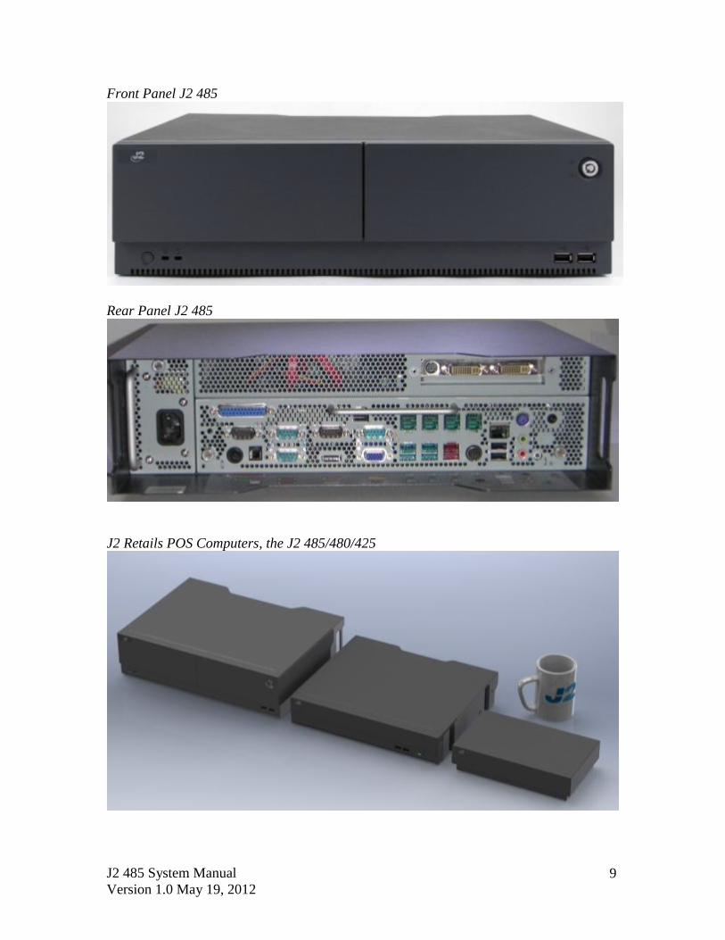
Front Panel J2 485
Rear Panel J2 485
J2 Retails POS Computers, the J2 485/480/425

J2 485 System Manual
Version 1.0 May 19, 2012 10
Features
Intel’s Desktop Processor Socket LGA 1155
By using the latest generation of Intel’s desktop processors and chipsets, code named
Sandy Bridge, the J2 485 supports a very wide range of processors. By taking advantage
of J2’s vast experience with notebook, desktop, and POS computer designs, we have
combined the features of all three for an optimal POS system design. The result is a POS
system that can utilize a desktop chipset that draws very little power and generates a low
amount of heat, similar to mobile chipsets and processors.
Notebook quality components are used in the processor, chipset, and power supply
circuitry, allowing for reduced heat generation and minimal power usage. Additionally,
the J2 485 takes full advantage of the low power features built into the Intel processor
and chipset to further reduce heat.
Hot Swappable RAID / Quad Hard Drives
Like the J2 650, the first integrated POS system on the market to offer a hot swappable
RAID feature, the J2 485 also supports this feature. The four internal 2.5 inch SATA hard
drives can be configured as a RAID array which gives true fault tolerance to the hard
drive subsystem.
DVD/CD Optical Drive
The J2 485 supports standard one DVD/CD optical drive with read/write capability.
Powered USB Ports / Power Port
Addressing the need for additional power ports, the J2 485 supports six +12V and one
+24V Powered USB port. The J2 485 can take advantage as well of the growing
availability of Powered USB products on the market.
In addition to the three Powered USB ports, the J2 485 also supports five powered serial
ports, VGA +12V power, a +24V printer power port, and four standard 2.0 USB ports.
By using a combination of all these powered ports, most all additional external power
supplies for devices such as monitors, scales, “Chip and Pin” devices, scanners, and many
others can be eliminated. This greatly saves space and reduces cost, cables and power
consumption and in most installations this means that only one AC power point is
needed. In addition, with the J2 optional UPS, all these devices will stay powered during
a power outage.

J2 485 System Manual
Version 1.0 May 19, 2012 11
UPS
Not your ordinary UPS, the J2 485 UPS is a DC, not an AC UPS. The UPS replaces the
internal power supply. Unlike an AC UPS the J2 UPS makes the 485 work more like a
notebook computer. In addition to running the J2 485 for up to one hour, the UPS will run
all the POS peripherals attached to the 485, including the printer. Because of the unique
design of the J2 UPS and power supply, the need for special AC power conditioning
devices is eliminated.
Printer Power Port
The 24 volt Printer Power Port can power most POS printers on the market, including the
popular Epson line of printers. When used along with the J2 UPS, if a power outage
should occur, the POS terminal can still operate and print receipts for up to one hour.
Also, when the J2 485 is turned off the printer is turned off also. This is very useful when
the auto power on/off feature of the 485 is used. This also applies to the +24V Powered
USB port.
Cooling System
Great attention was paid to the thermal solution of the J2 485; it is truly a unique feature.
The 485 can run as a fan-less or fan-cooled system. Because of the very wide range of
processors supported, thermal loads can range from 5 watts up to as high as 95 watts and
the J2 485 was designed to handle these thermal loads while still being super quiet. Two
smart fans are used in conjunction with an Embedded Controller (EC) to ensure that the
fans run at the lowest possible speed while still providing proper cooling. Fan speed
changes are controlled to produce the smallest acoustical signature possible. The J2 485
fans are the type used in Blade Servers and have a speed range from 3500~10,000 rpms
running at very high torque.
Fan-Off Mode
When using the i5 or lower performance processors, the J2 485 can run in a fan-off
configuration. In this mode the 485 is a fan-less convection-cooled device. This fan-less
operation may be required for high dust or other special environments.
This feature is unique to J2 and was supported by the J2 650 “Green Mode”. With the J2
485’s “Fan-Off” mode, the power is also greatly reduced by the nature of the processor
used, thereby reducing power consumption and further reducing the unit carbon footprint.
Versatility
The word versatility is the perfect choice word to describe the unique combination of
desirable features designed in to the powerful new J2 485 retail unit. The 485 is not just
one product, but a full product range contained all in one system. From fan-less thin
client to Quad Core RAID Server - the robust J2 485 does it all, with great reliability.

J2 485 System Manual
Version 1.0 May 19, 2012 12
System
Configurations
The J2 485 can be ordered or upgraded to many possible configurations. Selecting the
right combination of memory, processor, hard or solid state drive(s), and software drivers
can dramatically change the performance of the 485 system. For many users the standard
G530 2.4GHz dual core processor and 2GB of memory is perfect, as this is already more
powerful than most all POS systems; however some applications may require more horse
power. In this case the J2 485 could be configured with a quad core i5 or i7 processor.
J2 will be happy to help you determine what you require from the J2 485 to have the best
performance for your customer needs. For example, more memory may be added, or
sometimes a quad core processor and dual HDD with RAID can all be included. The J2
485 can do it all, low end to high end, and at a very reasonable and cost effective price.
Processor Support
The J2 485 supports a very wide range of Intel processor; each provides a different price
performance level. From Celeron dual core, Pentium dual core and -3, i5 and i7 dual a
quad core, with processor speeds from 2.4GHz to 3.4GHz, these are all supported by the
485.
The J2 485 comes standard with the Intel dual core 2.4GHz G530 processor, though it
can also be ordered with a different processor type if desired. The processor can be easily
upgraded by a qualified technician. The J2 485 uses the Intel defined LGA1155 socket.
Intel is constantly adding new processors, so please check with J2 for any additions since
publication of this manual.
The large heat sink, cooling fans, and fan controller (shown below) are designed to keep
everything running cool, quiet and reliably with the supported processors.
System, back view, cover off

Processors currently supported on the 485
Processor # Intel's Family name Clock Speed Max Turbo Frequency
# of Cores # of Threads Cache Embedded Fan-off mode
Graphics Speed MHz
VPro Max TDP
G530T Celeron 2.0 GHz Na 2 2 2MB No Yes 650/1000 No 35 W
G530 Celeron 2.4 GHz Na 2 2 2 MB No No 850/1000 No 65 W
G540 Celeron 2.5 GHz Na 2 2 2 MB Yes No 850/1000 No 65 W
G620T Pentium 2.2 GHz Na 2 2 3 MB 7 Year Yes 650/1100 No 35 W
G620 Pentium 2.6 GHz Na 2 2 3 MB No No 850/1100 No 65 W
G630 Pentium 2.7 GHz Na 2 2 3 MB No No 850/1100 No 65 W
G630T Pentium 2.3 GHz Na 2 2 3 MB No Yes 650/1100 No 35 W
G840 Pentium 2.8 GHz Na 2 2 3 MB No No 850/1100 No 65 W
G850 Pentium 2.9 GHz Na 2 2 3 MB Yes No 850/1100 No 65 W
G860 Pentium 3.0 GHz Na 2 2 3 MB No No 850/1100 No 65 W
i3-2100 i3 3.1 GHz Na 2 4 3 MB No No 850/1100 No 65 W
i3-2100T i3 2.5 GHz Na 2 4 3 MB 7 Year Yes 650/1100 No 35 W
i3-2120 i3 3.3 GHz Na 2 4 3 MB Yes No 850/1100 No 65 W
i3-2120T i3 2.6 GHz Na 2 4 3 MB No Yes 650/1100 No 35 W
i3-2125 i3 3.3 GHz Na 2 4 3 MB No No 850/1100 No 65 W
i3-2130 i3 3.4 GHz Na 2 4 3 MB No No 850/1100 No 65 W
i5-2390T i5 2.7 GHz 3.5 GHz 2 2 3 MB 7 Year Yes 650/1100 Yes 35 W
i5-2300 i5 2.8 GHz 3.1 GHz 4 4 6 MB No No 850/1100 No 95 W
i5-2310 i5 2.9 GHz 3.1 GHz 4 4 6 MB No No 850/1100 No 95 W
i5-2320 i5 3.0 GHz 3.1 GHz 4 4 6 MB No No 850/1100 No 95 W
i5-2400 i5 3.1 GHz 3.4 GHz 4 4 6 MB Yes No 850/1100 Yes 95 W
i5-2400S i5 2.5 GHz 3.3 GHz 4 4 6 MB No No 850/1100 Yes 65 W
i5-2500 i5 3.3 GHz 3.7 GHz 4 4 6 MB No No 850/1100 Yes 95 W
i5-2500S i5 2.7 GHz 3.7 GHz 4 4 6 MB No No 850/1100 Yes 65 W
i5-2500T i5 2.3 GHz 3.3 GHz 4 4 6 MB No Yes 650/1250 Yes 45 W
i7-2600 i7 3.4 GHz 3.8 GHz 4 8 8 MB Yes No 850/1350 Yes 95 W
i7-2600S i7 2.8 GHz 3.8 GHz 4 8 8 MB No No 850/1350 Yes 65 W
1: Processors with green shading would be standard J2 485 products.
2: Processors with blue shading are available but may require a minimum order quantity.
3: All processors shown above should work on the J2 485 but are not necessarily tested.
4: "7 Year" = support from Intel to J2 for 7 years, same as embedded products.
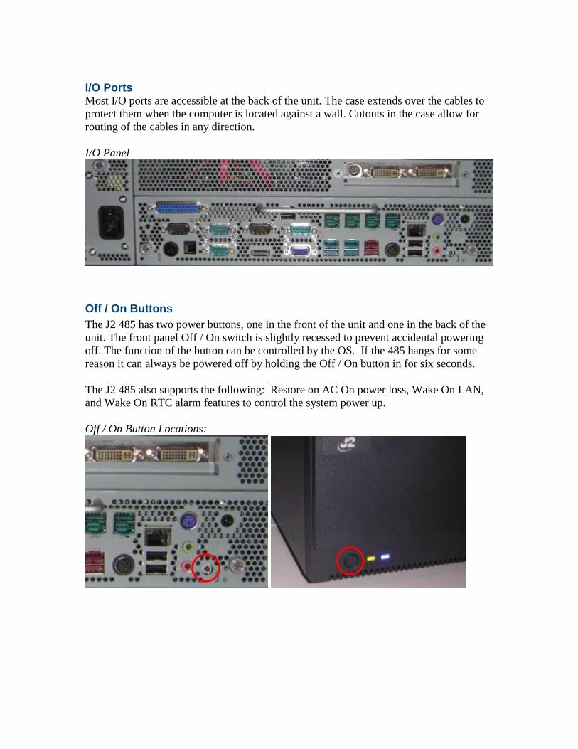
I/O Ports Most I/O ports are accessible at the back of the unit. The case extends over the cables to
protect them when the computer is located against a wall. Cutouts in the case allow for
routing of the cables in any direction.
I/O Panel
Off / On Buttons
The J2 485 has two power buttons, one in the front of the unit and one in the back of the
unit. The front panel Off / On switch is slightly recessed to prevent accidental powering
off. The function of the button can be controlled by the OS. If the 485 hangs for some
reason it can always be powered off by holding the Off / On button in for six seconds.
The J2 485 also supports the following: Restore on AC On power loss, Wake On LAN,
and Wake On RTC alarm features to control the system power up.
Off / On Button Locations:

J2 485 System Manual
Version 1.0 May 19, 2012 15
Front Panel LEDs
There are two front panel LED indicators, one green/amber LED and one blue LED. The
blue LED is active when either the HDD/SSD are being accessed. The green/amber LED
displays green when the unit is powered up, and shows amber when the unit is powered
down, and AC power applied indicates either stand-by or sleep mode.
Hard Disks
Up to four 2.5 inch SATA hard drives (HDD) or solid state drives (SSD) are supported.
These drives can be configured as standard hard drives or as a RAID array. The SATA
interface can support data transfer rates up to 3.0GB/s and supports AHCI and Hot
Swapping of hard drives.
Two of the four drive locations can be accessed from the front of the unit. With the front
panel key in the unlocked position the drive access door can be opened and easily
accessed with no tools. Just use the pull tab to slide the drives in and out

J2 485 System Manual
Version 1.0 May 19, 2012 16
The other two drives can easily be accessed by removing the top cover of the unit. The
cover can be removed without tools, as shown later in this manual. Once the cover is
removed from the HDD/SSD, the locking tab is moved to the vertical position, please see
below:
A carrying tray (four of which are supplied with the J2 485) fits onto a new drive without
tools. The drive can easily be slid into the drive bay by using the plastic pull tab. In a
RAID 1 configuration, a drive can be hot swapped, removed, or inserted with the power
on (see section on RAID setup).
J2 485 System Manual
Version 1.0 May 19, 2012 17
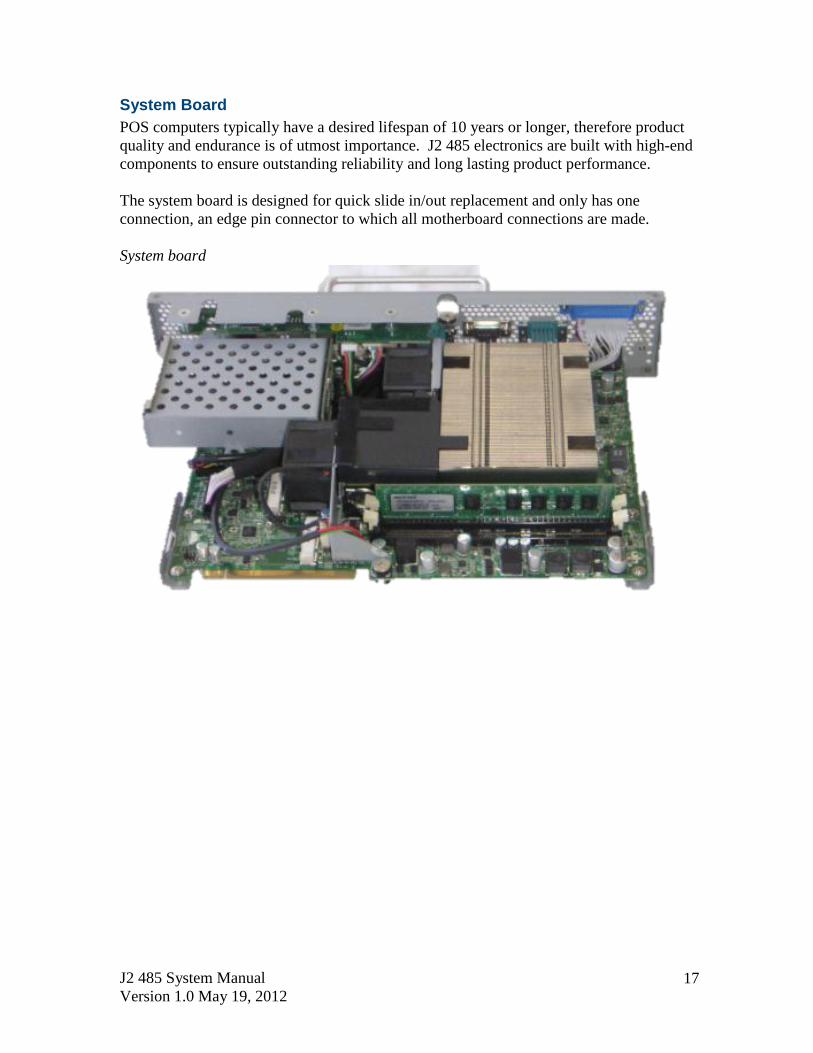
System Board
POS computers typically have a desired lifespan of 10 years or longer, therefore product
quality and endurance is of utmost importance. J2 485 electronics are built with high-end
components to ensure outstanding reliability and long lasting product performance.
The system board is designed for quick slide in/out replacement and only has one
connection, an edge pin connector to which all motherboard connections are made.
System board

J2 485 System Manual
Version 1.0 May 19, 2012 18
Video Ports
A standard PC VGA video port is supported on the J2 485 and can be set as the primary
or secondary display. The VGA video port has an industry standard HD DB15 connector.
When used with some J2 monitors the display can be powered by the J2 485 through this
connector.
The J2 485 also supports the newer digital video standard Display Port connector. This
connector supports a Display Port monitor or a HDMI display or DVI monitor. When
used with HMDI or DVI displays, a passive adaptor cable is used. When used with a
HDMI display, Audio is supported via the same HMDI cable.
The secondary video displays can be configured as a Twin, Intel Dual Display Clone, or
Extended Desktop. Most all monitor resolutions from 640 x 485 to 2560 x 2048 are
supported.
Both ports can be used at the same time and either display can be configured as the
primary display.
VGA and DisplayPort Video Ports (see below):
J2 485 System Manual
Version 1.0 May 19, 2012 19
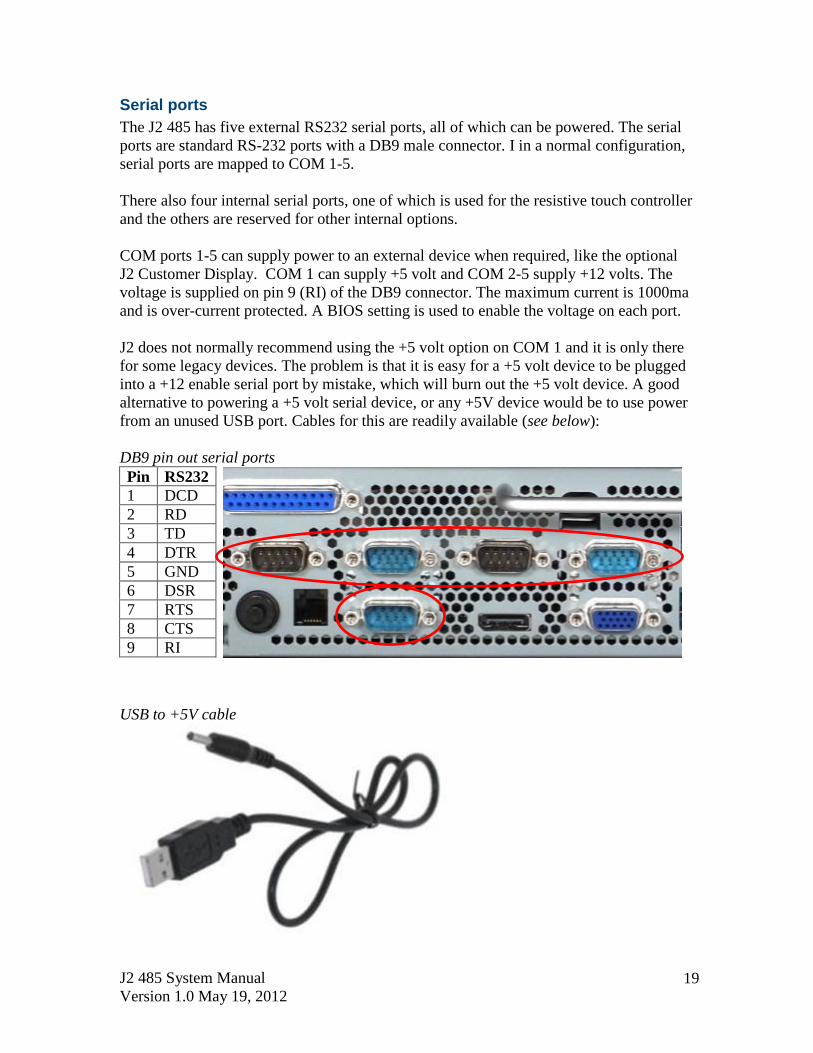
Serial ports
The J2 485 has five external RS232 serial ports, all of which can be powered. The serial
ports are standard RS-232 ports with a DB9 male connector. I in a normal configuration,
serial ports are mapped to COM 1-5.
There also four internal serial ports, one of which is used for the resistive touch controller
and the others are reserved for other internal options.
COM ports 1-5 can supply power to an external device when required, like the optional
J2 Customer Display. COM 1 can supply +5 volt and COM 2-5 supply +12 volts. The
voltage is supplied on pin 9 (RI) of the DB9 connector. The maximum current is 1000ma
and is over-current protected. A BIOS setting is used to enable the voltage on each port.
J2 does not normally recommend using the +5 volt option on COM 1 and it is only there
for some legacy devices. The problem is that it is easy for a +5 volt device to be plugged
into a +12 enable serial port by mistake, which will burn out the +5 volt device. A good
alternative to powering a +5 volt serial device, or any +5V device would be to use power
from an unused USB port. Cables for this are readily available (see below):
DB9 pin out serial ports
Pin RS232
1 DCD
2 RD
3 TD
4 DTR
5 GND
6 DSR
7 RTS
8 CTS
9 RI
USB to +5V cable

J2 485 System Manual
Version 1.0 May 19, 2012 20
USB Ports The J2 485 has a total of eleven external and one internal USB 2.0 ports. Of the eleven
external ports (see below) nine ports are located in the back of the unit and two are
located on the front panel of the unit for easy access. The one internal USB port is
designed for other optional internal devices. All the J2 485 USB ports can supply 1000ma
of power, 500ma more than the norm for USB specification.
Powered USB Ports
Of the eleven external USB 2.0 ports, seven are Powered USB ports. Located in the back
of the unit are six +12V PoweredUSB ports and one +24V PoweredUSB port. These
ports conform to the Powered USB standard.
It should be noted that these seven ports can also be used as standard USB ports as well.
Normal +5 USB devices will plug into the bottom half of the connector without a
problem.
USB Ports
Front Panel USB Ports

J2 485 System Manual
Version 1.0 May 19, 2012 21
Ethernet Connection
The J2 485 uses the Intel 82579LM Gigabit Ethernet controller. The Ethernet connector
is located in the back of the unit (shown below). The Ethernet controller supports Wake
on LAN, and the BIOS supports a PXE boot ROM. There are two LEDs on the LAN
connector: the Green LED lights up when the LINK signal is present and the Amber
LED lights comes on when there is LAN activity. This Ethernet supports Intel AMT
feature when used with the correct processor.
Ethernet Connector
Audio
The J2 485 uses the VIA1708B HD audio controller and there is one internal speaker.
Both a microphone jack and a headset jack are located in the back of the unit (seen
below),which allows for the connection of a microphone and headset, or audio out to
other devices. Audio is also output via the HDMI port when used.
Audio Jack Location

J2 485 System Manual
Version 1.0 May 19, 2012 22
PS/2 Keyboard Port
The J2 485 supports one PS/2 port. This interfaces is commonly used for a hand laser
scanner, but can also be used for any PS/2 Keyboard type device.
PS/2 Keyboard Port Location
Parallel Port
The J2 485 supports one parallel port. This is the standard PC type 8 bit port.
PCI-E Expansion Slot
The J2 485 supports one ¾ length PCI Express expansion slot. (Or alternatively it
supports a PCI expansion with separate riser card.)

J2 485 System Manual
Version 1.0 May 19, 2012 23
Printer Power Port
The Printer Power Port allows an industry standard POS printer to be powered from the
J2 485, eliminating the need for a separate external power supply for the printer.
The Printer Power Port supplies 24 VDC 2.5 amps and 6.0 amp surge current which will
run most POS printers on the market. The power cable for this port is supplied standard
with the J2 485 unit. The Printer Power Port will also supply power to a printer even
when running with the optional UPS feature. When the J2 485 is powered down,the
power to the printer is turned off. This same power circuit is used by the +24 Powered
USB port and normally only one +24V device is supported at one time, unless it can be
ensured that only one device prints at a time.
Printer Power Port Printer Power Port Cable
Cash Drawer Port
The J2 485 is equipped with one Cash Drawer Port that will support one or two cash
drawers. This port is located in the back of the unit and uses the industry standard RJ-11
connector and pin out (illustrated below). This pin-out is the same as used by EPSON
printers, and cables for the EPSON printer normally work fine with the J2 485.
Cash Drawer Ports

J2 485 System Manual
Version 1.0 May 19, 2012 24
6
1
Cash Drawer 1 Pin Assignment
Pin Signal
1 GND
2 CD1 SOLENOID
3 STATUS / STATUS CD1
4 24V
5 CD2 SOLENOID
6 GND / STATUS CD2
The application may address the Cash Drawer port in two ways:
1) Using J2-supplied OPOS drivers for Windows.
2) Direct access to the I/O ports
3) J2-supplied Virtual Serial Cash Drawer Emulator
Cash Drawer Controller Register
The Cash Drawer Controller use one I/O address to control the Cash Drawer.
Register Location: 48Ch
Attribute: Read / Write
Size: 8bit
BIT BIT7 BIT6 BIT5 BIT4 BIT3 BIT2 BIT1 BIT0
Attribute Read Reserved Write Reserved
7 6 5 4 3 2 1 0
X X X X X
Reserved
Cash Drawer 1 fire
Cash Drawer 2 fire
Reserved
Cash Drawer 1 status
Reserved
The “Y” cable used to support two cash drawers on the one RJ-11 is the same as the one
used on Epson printers.
J2 485 System Manual
Version 1.0 May 19, 2012 25
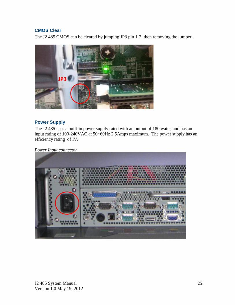
CMOS Clear
The J2 485 CMOS can be cleared by jumping JP3 pin 1-2, then removing the jumper.
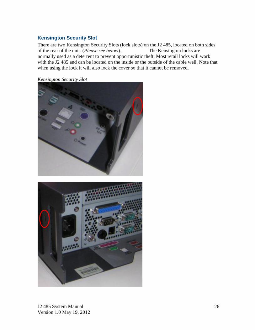
Power Supply
The J2 485 uses a built-in power supply rated with an output of 180 watts, and has an
input rating of 100-240VAC at 50~60Hz 2.5Amps maximum. The power supply has an
efficiency rating of IV.
Power Input connector
JP3
J2 485 System Manual
Version 1.0 May 19, 2012 26
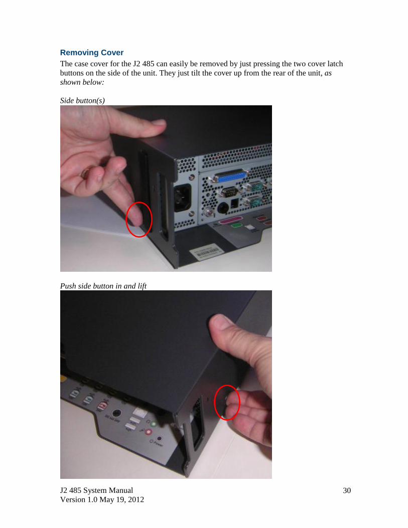
Kensington Security Slot
There are two Kensington Security Slots (lock slots) on the J2 485, located on both sides
of the rear of the unit. (Please see below). The Kensington locks are
normally used as a deterrent to prevent opportunistic theft. Most retail locks will work
with the J2 485 and can be located on the inside or the outside of the cable well. Note that
when using the lock it will also lock the cover so that it cannot be removed.
Kensington Security Slot

J2 485 System Manual
Version 1.0 May 19, 2012 27
Typical Power Consumption
The typical power consumption of the J2 485 is lower that most desktop computers.
Using the latest generation Intel’s Desktop processors and chipset allows for much lower
power consumption than previous generations of POS computers. This superb
combination, coupled with proper system configuration, greatly reduces the system total
carbon foot print.
Test conditions
Voltage: 220VAC 50Hz, measured voltage 236 VAC
OS: POSReady 7
Heavy Load Program: PassMark BurnInTest defaults values
Maximum load: PassMark BurnInTest Max CPU Temp
Temperature: 26c
All systems were tested in their standard hard drive configuration, results are +/- 15%.
J2 485 i5-2400 3.10GHz
1: Normal application including most POS software 20 watts
2: Very heavy load application 65 watts
3: Maximum load (J2 485 only, not including peripherals) 96 watts
4: Standby, unit off, waiting for wake on LAN, RTC or power button >4 watts

J2 485 System Manual
Version 1.0 May 19, 2012 28
Service The J2 485 is designed to be fully and easily serviced - system updates, memory
upgrades, or storage device swaps and/or upgrades can all be accomplished without using
any tools!
Removing the System Board
To remove the System Board: loosen the two thumbscrews located on the back of the unit
(as shown below). Then simply use the handle to slide the system board out.
Note: Proper anti-static procedures are required when handling the system board.
Loosen Thumb Screws
Slide system board out by pulling on the handle

J2 485 System Manual
Version 1.0 May 19, 2012 29
Removing the Power Supply
Warning! To remove the Power Supply first un-plug the AC power cord.
Then loosen the thumbscrew located on the back of the unit (as shown below), and
simply use the handle to slide the power supply out.
Removing the power supply by sliding out
J2 485 System Manual
Version 1.0 May 19, 2012 30
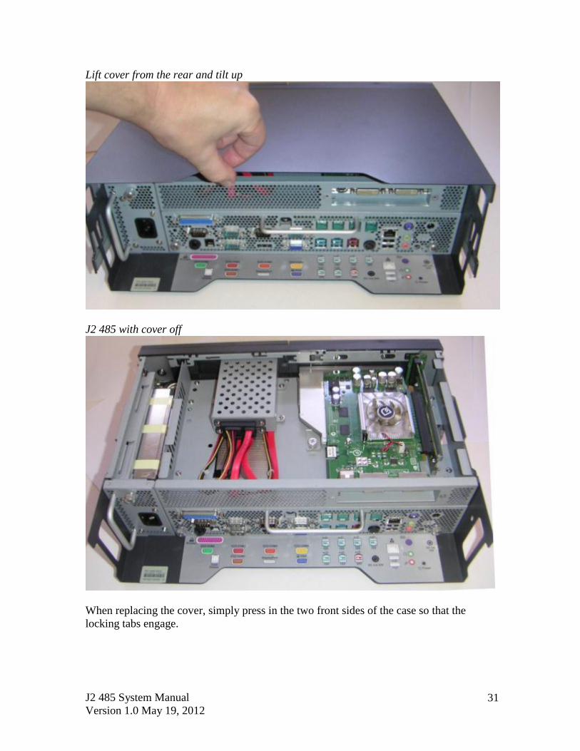
Removing Cover
The case cover for the J2 485 can easily be removed by just pressing the two cover latch
buttons on the side of the unit. They just tilt the cover up from the rear of the unit, as
shown below:
Side button(s)
Push side button in and lift
J2 485 System Manual
Version 1.0 May 19, 2012 31
Lift cover from the rear and tilt up
J2 485 with cover off
When replacing the cover, simply press in the two front sides of the case so that the
locking tabs engage.

J2 485 System Manual
Version 1.0 May 19, 2012 32
Adding Memory
Note: Proper anti-static procedures are required when handling the system board.
To add memory, slide the system board out of the unit. You can now access the two
memory sockets, note that the order in which the memory is populated does not matter.
The J2 485 supports up to 16GB of memory in two sockets. Memory type is 240 DIMM
DDR3 1066/1333.
Memory sockets
Changing the Processor
To change the processor, be sure to first start by working in an anti-static workplace
with proper grounding. Remove the systems board from the system, now remove the
black plastic fan duct.
Loosen the four spring-loaded screws that secure the processor heat sink by turning each
screw about two turns at a time so that the pressure is removed from the socket evenly.
Once the screws are free you will now be able to remove the heat sink. It will stick
because of the heat sink compound, so take care to move it gently from side to side until
it comes off. Set the heat sink aside, top side down.
You can now remove the processor from the socket. Push the locking lever down, push
out from the locking tab, and move it up (as shown?). Now carefully lift the cover up and
you can remove the processor. **Be sure only to touch the edges of the processor and
do not touch the processor pads of the socket pins. These socket pins are very easy
to bend and damage to the socket is not covered by J2 warranty.**
J2 485 System Manual
Version 1.0 May 19, 2012 33
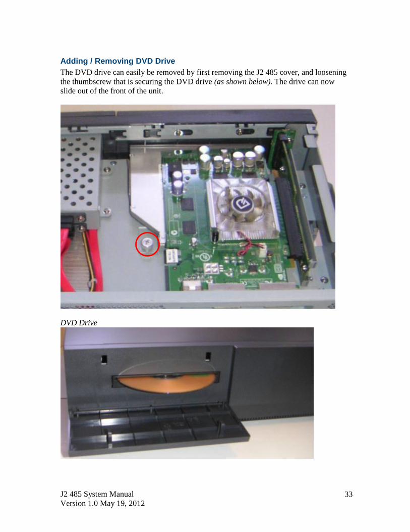
Adding / Removing DVD Drive
The DVD drive can easily be removed by first removing the J2 485 cover, and loosening
the thumbscrew that is securing the DVD drive (as shown below). The drive can now
slide out of the front of the unit.
DVD Drive

J2 485 System Manual
Version 1.0 May 19, 2012 34
BIOS Setup
Entering the BIOS Setup
To enter the BIOS Setup, turn on or reboot the J2 485 and press the DEL key after the
BIOS sign-on screen appears. The main menu of the BIOS setup will be displayed; this
can take a few seconds. If the supervisor password is set, you must enter it here. The area
on the right side of the screen displays a help window for the current screen or BIOS
option.
BIOS setting should only be change by qualified personnel, as changing some
settings can cause the system to function improperly.
Main, System Overview
In this screen the system time and date are displayed and can be set. The time and date
can also be set through the OS. This screen also displays the BIOS version (project),
BIOS Build Date, CPU type, CPU speed and DRAM memory size, Product type, System
Serial Number and mother board revision. The serial number of the mother board and the
system are the same.
Main screen

J2 485 System Manual
Version 1.0 May 19, 2012 35
Advanced Settings
This menu contains settings to control a number of system functions, most settings are
self-explanatory;
Advanced Setting Screen
Launch PXE ROM
This setting enables the built- in PXE LAN remote boot rom. This allows the system to
run as a diskless workstation, or also to be able to download a drive image to a blank
drive. When enabled, a message screen will appear and Shift-F10 can be typed to access
the PXE ROM option. This option is located on the “Advanced” tab, as shown above:
J2 485 System Manual
Version 1.0 May 19, 2012 36
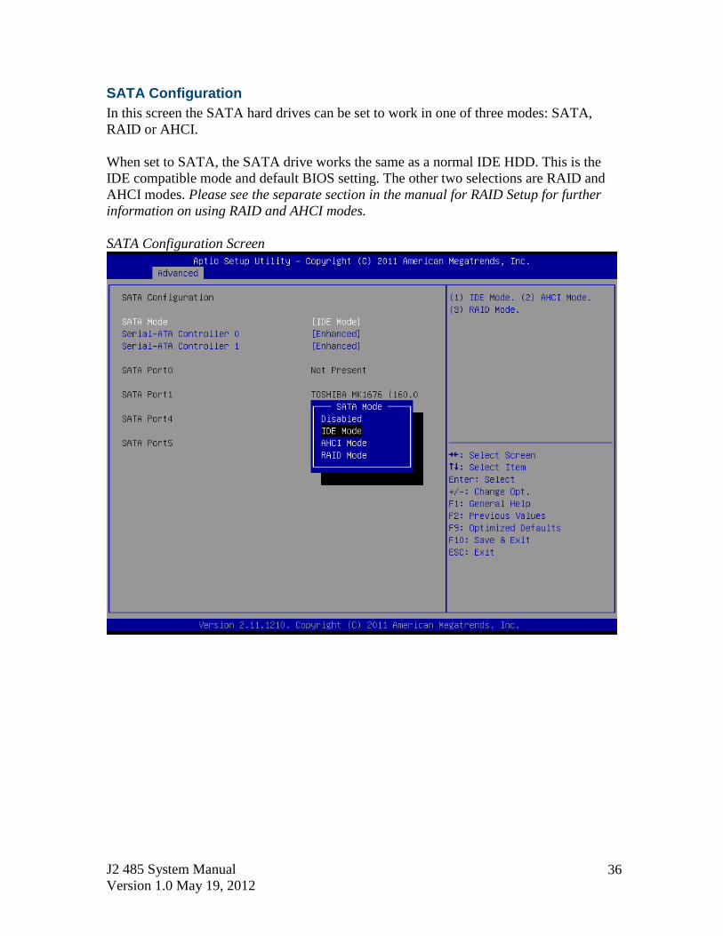
SATA Configuration
In this screen the SATA hard drives can be set to work in one of three modes: SATA,
RAID or AHCI.
When set to SATA, the SATA drive works the same as a normal IDE HDD. This is the
IDE compatible mode and default BIOS setting. The other two selections are RAID and
AHCI modes. Please see the separate section in the manual for RAID Setup for further
information on using RAID and AHCI modes.
SATA Configuration Screen

J2 485 System Manual
Version 1.0 May 19, 2012 37
Peripheral Power and LCD Brightness Configuration
This submenu allows for the enabling of power for the serial ports, default cash drawer,
pulse timing, and power for a J2-supplied VGA port monitor.
Brightness control is not used on the J2 485.
Power enable for Serial Ports

J2 485 System Manual
Version 1.0 May 19, 2012 38
Power Configure Screen
Power Configure Screen
Restore on AC Power Loss
The J2 485 has three options should AC power become lost and then later restored. There
is Power Off (stay turned off), Power On (turn on when AC restored), or Last State. The
Last State setting will cause the unit to turn on (if it was on when AC power was lost), or
it will stay off ( if the unit was off when AC power was lost).
Wake on LAN
Wake on LAN is enabled by default but can be disabled in this screen.
RTC Configuration
The RTC has an alarm function that can be used to turn the J2 485 on at a preset time of
day. This function is enabled by this setting. The wake up time can also be set here.
J2 also has a utility option available to set the wake-up time from Windows. This is more
versatile than the BIOS setting, as it allows for more than one time of day to be set, as
well as days of the week to turn on if desired.

J2 485 System Manual
Version 1.0 May 19, 2012 39
Boot Settings
If more than one bootable device is in the system, the boot order can be set in this menu.
If a bootable USB storage device is plugged in at boot up, the J2 485 will boot from that
device by default. If this is not desired, the boot order can be changed here. A list of
detected drives will be displayed with the current boot order.
Boot Settings Screen
Display OEM Logo
The BIOS can display two types of OEM logos on boot up. The default is a small J2 logo
in the upper left hand corner. With this setting BIOS POST test messages can be seen
during boot up. The second type which is enabled by this entry is a full screen J2 logo.
When this logo is selected the BIOS POST messages cannot be seen. The BIOS setup can
still be entered by typing the DEL key a few seconds after the logo appears.
Customer logos can replace the J2 logos when required. Please contact J2 for this option.

J2 485 System Manual
Version 1.0 May 19, 2012 40
Exit Options
After making any changes to the BIOS settings, new information can be saved from this
Exit Options screen. Any changes can be discarded as well, or the factory BIOS defaults
can be loaded. Typing the F9 key at any time will load the “Optimized Values” which
resets all BIOS setting to the factory defaults.
It should be noted that to save changes to the BIOS setup, the F10 key can be typed from
any screen to save the BIOS changes. It is not necessary to exit setup from this screen.
To discard any BIOS setup changes, simplytype the ESC key from any screen to exit.
Exit Options Screen

J2 485 System Manual
Version 1.0 May 19, 2012 41
Driver Installation, Windows
Chipset Driver Installation
The chipset driver is needed to get the full potential from the J2 485 chipset. It should be
loaded before other drivers and also first thing after booting. The drivers can be
downloaded from the J2 web site:
http://www.j2retailsystems.com/support/485/Chipset/.
After extracting the drivers to a temporary folder, run Setup.
Just answer Next or Yes to all the screen prompts and the drivers will install.
Graphics Driver Installation
You can download the J2 485 graphics driver from the J2 web site at:
http://www.j2retailsystems.com/support/485/Graphics/.
This is an .exe file so just run it and answer Next or Yes to all screen prompts and the
drivers will install. The last screen will ask if you want to reboot, answer Yes.

J2 485 System Manual
Version 1.0 May 19, 2012 42
Audio Driver Installation
The Audio Drivers can be downloaded from the J2 web site at:
http://www.j2retailsystems.com/support/485/Audio/.
After extracting the driver to a temporary folder, run Setup, and then follow the
instructions below:
First Audio setup screen
Just click on Next to install the Audio Driver.
Second Audio setup screen

J2 485 System Manual
Version 1.0 May 19, 2012 43
Check the Codec Driver box, and then click Next. Answer Next to any more dialog
boxes, then Finish. The system will need to be rebooted before the audio drivers take
effect.
LAN Driver Installation
The LAN drivers can be downloaded from the J2 web site:
http://www.j2retailsystems.com/support/485/LAN/.
After extracting the driver to a temporary folder, run Setup. Just answer Next or Yes to
all the screen prompts and the driver will install.
LAN driver install screen

J2 485 System Manual
Version 1.0 May 19, 2012 44
OPOS drivers
The OPOS driver for the J2 485 supports the following: Cash Drawer ports, optional
MSR, optional 2x20 character Customer Display, and the optional iButton reader.
The OPOS driver may be downloaded from the J2 web site at:
http://www.j2retailsystems.com/support/485/.
Just run the OPOS setup.exe file to install.

J2 485 System Manual
Version 1.0 May 19, 2012 45
J2 Health J2 has a standard program that works with all its POS products called J2 Health. This
program is used in either a standalone mode or in conjunction with J2 remote
monitor/asset tracking software. The J2 Health program monitors different aspects of the
POS hardware to ensure the hardware is running within specification. For the J2 485 it
monitors critical system voltages, as well as system and CPU temperatures.
Installation
The utility can be downloaded from the J2 web site:
http://support.j2rs.com/Utilities/Health/ To install just unzip anywhere and run setup.
Like other J2 utilities it can be uninstalled through the Windows control panel.
Tray Icon
Once installed and the system has rebooted, J2 Health will be running in the background.
The J2 health icon will appear in the task bar tray:
Right-clicking on this icon displays different Health options, shown below:
The current health values will display by clicking on “Display Health Values”.
A sample screen is shown below:

J2 485 System Manual
Version 1.0 May 19, 2012 46
As can be seen above when running on the J2 485, the J2 Health program displays critical
system voltages and system and CPU Core temperatures. For other J2 POS systems J2
Health may display more or less information. An example would be the J2 680 unit,
which in addition to the above information, would also display the fan speed of the two
J2 680 fans.
Logging to File
The J2 Health program can log the health data to a file in the csv text format for
importing to other programs, like Excel. This can be handy for finding “time of day”
related problems.
When logging is enabled, the tray icon Rx symbol will change to red to indicate logging
in is taking place.

J2 485 System Manual
Version 1.0 May 19, 2012 47
Registry Entries
The J2 Health program creates registry entries for the different health values. Dynamic
values are updated at the user defined interval, which is by default 5 seconds. Other
software may use these registry entries to access the J2 health information.
J2 485 Health keys are shown below:
J2 Remote Monitoring Software
J2 now offers a full remote monitoring and asset tracking solution option that works in
conjunction with J2 Health to ensure the highest uptime possible of your POS hardware.
Please contact J2 sales for more information on this fully customizable, remote monitor
solution.
For more information, please visit us at
http://www.j2retailsystems.com/newsarticle.php?news_id=57

J2 485 System Manual
Version 1.0 May 19, 2012 48
SMI BIOS Info Utility The J2 SMI BIOS Info program allows for the reading of all populated BIOS DMI/SMI
information. With some J2 products including the J2 485, this information also includes
dynamic system health information. Normally this key DMI health information BIOS is
only supported on very high end servers. Now J2 Retail brings this feature to POS
hardware.
The J2 SMI BIOS Info program will run on any J2 POS hardware or for that fact on any
PC hardware. It can display all DMI/SMI information on a formatted form.
Installation
The utility can be downloaded from the J2 web site: http://support.j2rs.com/Utilities/
To install just unzip anywhere and run as you wish to run the utility form.
Operations
Just click on the .exe file to run. The following screen will be displayed (see below).
Note that the health data will only display on newer J2 systems that support the dynamic
DMI health BIOS.

J2 485 System Manual
Version 1.0 May 19, 2012 49
Cash Drawer Test Utility J2 has a generic cash drawer test utility that works on all J2 products including the new
J2 485 computer.
Installation
The utility can be downloaded from the J2 web site: http://support.j2rs.com/Utilities/
To install just unzip anywhere and run as you wish to download the utility form.
Operation
Just run the cash drawer test from whatever folder it was installed into. Use the “Use
Direct I/O Port 48c” setting to test the cash drawer(s). See example below:
The “Use Comm Port 10 & 11” option is to test the cash drawer you set up using the J2
virtual serial ports program. The virtual serial port program must be installed with the
cash drawer virtual serial ports set to Comm 10 & 11.

J2 485 System Manual
Version 1.0 May 19, 2012 50
J2 Virtual Serial Ports Drivers
Virtual serial ports can be used for the cash drawers, virtual 2x20 line display on the
optional 10.1 LCD, Smart UPS, MSR and iButton.
To open the virtual serial cash drawer, send a bell character to the Com port it is assigned
to. (The bell character is the ASCII 07 hex character “Control G.”) The open/close
status of the drawer may be obtained by reading the status bits of its COM port. The
drawer open/close status will be reflected on the CTS and RI bits, either bit may be used.
This virtual COM port driver is designed to work the same as a hardware serial cash
drawer and will work with drivers for serial cash drawers.

J2 485 System Manual
Version 1.0 May 19, 2012 51
RAID
RAID Overview
The J2 485 uses the Intel Matrix Storage Technology to allow the two internal 2.5 inch
hard drives to be configured as a RAID array. The J2 485 supports RAID 0, RAID 1 and
Intel Matrix RAID which combines the benefits of two RAID volumes in a single RAID
array.
If you are not currently familiar with RAID arrays Intel has a good white paper on the
subject at: http://www.intel.com/design/chipsets/applnots/310855.htm
There are a number of benefits to using the RAID feature:
Protection is one benefit. When using a RAID 1 array, data is protected by mirroring.
The primary RAID volume is duplicated automatically on the second drive, a mirror
image of the first. If one of the two hard drives fails, the system will still keep working.
The bad hard drive can be replaced while the system is running. This is called hot
swapping or hot plug. The new drive will automatically be updated to a mirror image of
the working drive.
Performance is another feature RAID can provide. When configured as a RAID 0 array
the two drives in the RAID array are striped. With striping, data is split between two
drives. This allows the J2 485 to read the data more than twice as fast as with a single
drive. The performance can be accomplished more quickly because the Intel RAID driver
also uses the AHCI NCQ function built into the SATA drives.
Protection and Performance can be mixed using an Intel Matrix RAID configuration,
whereby a RAID 1 and RAID 0 can be setup on the same RAID array. Mission critical
data can be stored in the RAID 1 volume and data requiring performance can be stored on
the RAID 0 volume.
AHCI
AHCI stands for Advanced Host Controller Interface and is a feature of the SATA
interface that allows for Hot Swapping and Native Command Queuing (NCQ).
NCQ allows multiple commands to be sent to the hard drive at one time. The drive
decides the best way to order the commands for the best performance from the drive.
AHCI is enabled when RAID mode is selected in the BIOS setup.
To use AHCI drivers from Intel the BIOS must be set to RAID, not AHCI. The AHCI
mode uses the same drivers as used for RAID. Follow the instructions for installing the
RAID drivers, however set the HDD as a Non-RAID Disk in the RAID BIOS setup.

J2 485 System Manual
Version 1.0 May 19, 2012 52
Enabling RAID in the BIOS
The Intel manual for the Intel Matrix Storage Manager covers this same information
given below in more detail and can be downloaded from the J2 web site. The
documentation below is tailored for the J2 485 only.
Link: http://www.j2retailsystems.com/support/485/RAID/
Perform the following steps to enable the RAID option in the system BIOS:
1. Enter the BIOS Setup program by pressing the DEL key after the BIOS sign-on
screen appears.
2. Select the Advanced menu, and then the SATA Configuration menu.
3. Switch the Configure SATA Ports option from SATA to RAID.
4. Press the F10 key to save the BIOS settings and exit the BIOS Setup program.
RAID Volume Creation
Perform the following steps to create a RAID volume:
1. When the Intel Matrix Storage Manager Option ROM status screen appears
during POST, press the Ctrl and i keys at the same time to enter the Intel Matrix
Storage Manager Option ROM user interface.
2. Select Option 1: Create RAID Volume and press the Enter key.
3. Use the up or down arrow keys to select the RAID level and press the Enter key.
4. Unless you have selected RAID 1, use the up or down arrow keys to select the
stripe size and press the Enter key.
5. Press the Enter key to select the physical disks.
6. Select the appropriate number of hard drives by using the up or down arrow keys
to scroll through the list of hard drives and pressing the Space key to select the
drive. When finished, press the Enter key.
7. Select the volume size and press the Enter key.
8. Press the Enter key to create the volume. At the prompt, press the Y key to
confirm volume creation.
9. Select Option 4: Exit and press the Enter key. Press the Y key to confirm exit.
F6 Installation Method
Note: For this step you will need both a USB CD ROM and a USB Floppy.
Drivers can be downloaded here: http://www.j2retailsystems.com/support/485/RAID/
(continued on next page)

J2 485 System Manual
Version 1.0 May 19, 2012 53
Perform the following steps to install the Intel Matrix Storage Manager driver during
operating system setup:
1. Press the F6 key when prompted in the status line with the Press F6, if you need
to install a third party SCSI or RAID driver message. This message appears at the
beginning of Windows XP setup (during text-mode phase).
Note: Nothing will happen immediately after pressing F6. Setup will temporarily
continue loading drivers. You will then be prompted with a screen asking you to
load support for mass storage device(s).
2. Press the S key to Specify Additional Device.
3. You will be prompted to Please insert the disk labeled Manufacturer-supplied
hardware support disk into Drive A: When prompted, insert the floppy disk
containing the following files: IAAHCI.INF, IAAHCI.CAT, IASTOR.INF,
IASTOR.CAT, IASTOR.SYS, and TXTSETUP.OEM and press the Enter key.
4. After pressing Enter, you should be presented with a list of available SCSI
Adapters. Select your controller from the list. The J2 485 uses the ICH8R driver.
5. The next screen should confirm your selected controller. Press the Enter key
again to continue.
6. At this point, you have successfully F6'd in the Intel Matrix Storage Manager
driver and Windows setup should continue. Leave the floppy disk in the floppy
drive until the system reboots. Windows setup will need to copy the files from the
floppy again to the Windows installation folders. Once Windows setup has copied
these files again, you should then remove the floppy diskette so that Windows
setup can reboot as needed.
7. During Windows setup, create a partition and file system on the RAID volume as
you would on any physical disk.
Installing the Intel Matrix Storage Manager Software
Once XP is booted you can install the Intel Matrix Storage Manager by just running the
iata82_enu.exe install program. Just answer “Next” to all questions and the software will
install. The software should now be working. Please refer to Intel’s documentation for
more information at manual70.pdf.
Hot Swapping RAID 1 drives
If a RAID 1 drive fails, the Matrix Storage Manager will warn the user that a drive has
failed. A small icon appears, as shown below, to indicate a drive has failed.
Drive Failed Icon in tray

J2 485 System Manual
Version 1.0 May 19, 2012 54
If a hot spare is available, all that needs to be done is to swap the bad drive with the hot
spare. Be sure to change the correct drive.
SATA Ports 0 corresponds to the HDD 0, the top drive in the HDD bay; and SATA Ports
1 corresponds to the HDD 1, the bottom drive in the HDD bay.
Power to the system does not need to be turned off, and the system will still operate.
First remove the bad drive. After removing the bad drive insert the hot spare into the J2
485. In the Intel Matrix Storage Manager select Advance Mode; and under the Actions
tab select “Rescan for Plug and Play Devices”.
Rescan for Plug and Play Devices screen shot
This will cause the drive to be detected by the driver.
Drive detected

J2 485 System Manual
Version 1.0 May 19, 2012 55
The RAID will now rebuild an image of the good drive to the hot spare.
Rebuilding
Rebuilt
The RAID has now mirrored the drive and the system is now protected for a drive failure.
Note: Please refer to J2’s “Using RAID in a Point of Sale Environment” white paper for
more information on using the 485 RAID function. (Available September 2008)

J2 485 System Manual
Version 1.0 May 19, 2012 56
Contact Information
European Office
J2 Retail Systems Ltd.
J2 House
Clayton Road, Birchwood
Warrington WA3 6RP
United Kingdom
44 (0) 1925 817003 Phone
44 (0) 1925 811989 Fax
USA Office
J2 Retail Systems Inc.
9251 Irvine Boulevard
Irvine, CA 92618
USA (714) 669-3111 Phone
(714) 669-3133 Fax
Australian Office
J2 Retail Systems Pty Ltd
Unit 6 83/85 Boundary Road
Mortdale NSW 2223
Australia
02 9584 5222 Phone
02 9584 1500 Fax
Website
http://www.j2retailsystems.com