j. park and m. garces infrasound laboratory of the university of hawaii a rotary subwoofer as an...
TRANSCRIPT

J. Park and M. GarcesInfrasound Laboratory of the University of Hawaii
A Rotary Subwoofer as an Infrasonic Source
Infrasound Technology Workshop, Bermuda, November 2008

Rotary Subwoofer : Kona Infrasound Generator (KING)
• Compact, portable infrasonic source

KING Installation• Matched amplifier, fitted baffle, ISLA as back volume
2 4 6 8 10 12 14 16 18 20R ange (m )
0
5
10
15
20
25
30
Loss
(dB
)
0
5
10
15
20
25
3010 log(r)
20 log(r)
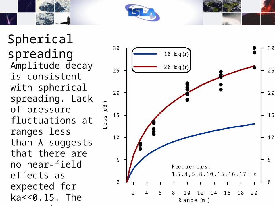
Frequencies:1.5, 4 , 5, 8 , 10, 15, 16, 17 H z
Amplitude decay is consistent with spherical spreading. Lack of pressure fluctuations at ranges less than λ suggests that there are no near-field effects as expected for ka<<0.15. The source is compact.
Spherical spreading

Beampatterns measured from 0-90o at a range of 1m.
Note that the on-axis (0o) response is ~2 dB less than the off-axis maximum.
At ka<<0.15, we expect strictly monopole radiation….
1m
2
1
Sin Wave 2007273
6
54
3

Sin Wave 2007260
Function Generator Output Voltage at Speaker Input
Noise Floor Fan OffNoise Floor Fan On1 Hz Sin 3 & 1 VRMS
1 Hz Sin 2 VRMS
4 Hz Sin 3 VRMS
8 Hz Sin 4 VRMS
16 Hz Sin 5 VRMS
With fan motor off and no amplifier gain, function generator output/speaker input are decoupled (blue). With fan motor on, no amplifier gain (green), fan components are observed at the speaker input terminals. With fan motor on and amplifier gain applied, there is an impressive coupling of power back to the speaker inputs, presumably from lack of isolation between the motor, speaker electromotive coil and motor controller. Note that the ‘pure sin wave’ frequencies (1, 4, 8, 16 Hz) output by the function generator are not tonal, i.e. the frequency is not stable with the feedback. Amplitude fluctuations were also observed in the input timeseries.
1m
1m
1m3
2
1
5
4
1m
1m
6
No Circuit Isolation

031
o18
20m
Speaker Axis 032o
Sin Wave 2007305
Fan Speed: Ω=17 Hz (1020 RPM)

1.8 km Range Test
4 Hz
8 Hz
12 Hz
16 Hz

~135 dB @ source!
22 dB
1.8 km Range Test
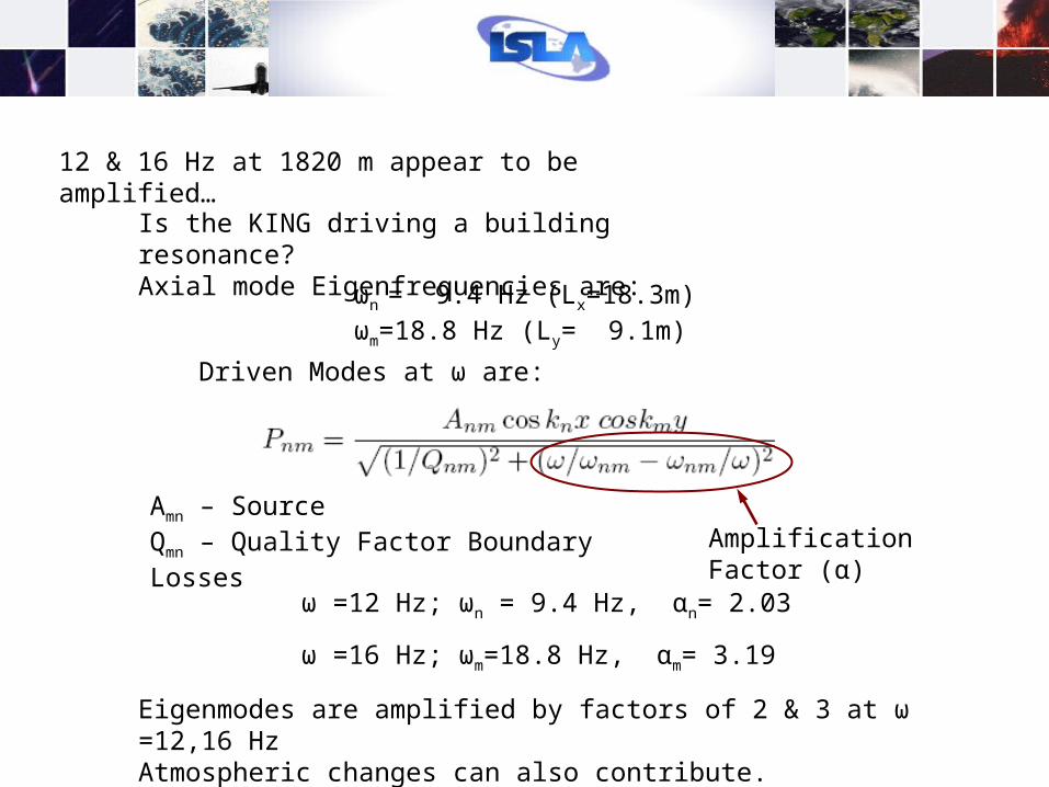
12 & 16 Hz at 1820 m appear to be amplified…
Is the KING driving a building resonance?Axial mode Eigenfrequencies are:
ωn = 9.4 Hz (Lx=18.3m) ωm=18.8 Hz (Ly= 9.1m)
Driven Modes at ω are:
Amn – Source Qmn – Quality Factor Boundary Losses Amplification Factor (α)
ω =12 Hz; ωn = 9.4 Hz, αn= 2.03
ω =16 Hz; ωm=18.8 Hz, αm= 3.19
Eigenmodes are amplified by factors of 2 & 3 at ω =12,16 HzAtmospheric changes can also contribute.

A Simple Source Particle Velocity Model
Ro
Ri
ωΩ
BL
BW
BLω
Ω Ro
ωB
W/2
Ω Ri
Ω
Vω
VΩ
ω θvΩ
n·vΩ^
vω
BW
Blade dynamics can express an effective particle velocity:
Which can be resolved into surface normal velocity components:
Assume that with Ω > ω, a coherent annular ring of area π(Ro
2 - Ri2) with an effective
particle velocity Vn is produced
Evaluate Rayleigh’s Integral for pressure at field point x:

Good Results: Ω/ω > 2
Model Results (on-axis)
Bad Results: Ω/ω < 2

Preliminary Model Results
Beampatterns showed on-axis (0o) response is ~2 dB less than the off-axis maximum. At ka<<0.15, we expect strictly monopole radiation….
Model results with the addition of a plane wave from the building wall/baffle indicates a pressure reduction on-axis.
The amplitude of reduction is less than the ~2 dB observed.

Array Calibration
Test I59US sonification with prototype system

Array Calibration
Test I59US sonification with prototype system

Model Result Hypothesis
KING has a non-zero radiation resistance (real part of radiation impedence) even though ka<<1.
Radiation impedance changes from reactance dominated (mass loading) to resistance dominated (fluid displacement) by virtue of the stream particle velocities.
High transduction efficiency: The electric motor that drives the blades at frequency Ω is the primary accelerator of particle velocity.
Structural backvolume eigenmodes can be driven and may contribute to radiation.
Building wall/baffle plane wave may affect pressure distribution.
The effective particle velocity model breaks down when Ω/ω < 2.

• No circuit isolation between fan motor and electromotive coil that modulates fan blades induces feedback to the speaker input. Shielding the fan motor reduces EMI by an order of magnitude. Shielding the input and measurement cables reduces EMI.
• Sound intensity decay is approximately 1/r2 even at r << . The source is compact.
• Transfer function values (dB re Pa/V) are > -5dB, the signal to acoustic power efficiency is better than a conventional voice-coil driven diaphragm.
• SPL is in range of 120 dB re 20 µPa from 4-16 Hz. Power levels are dependent on fan speed. Higher fan speed creates higher particle velocities.
• High SPL and efficiency are a result of fluid displacement Radiation Impedence matching from the high particle velocities.
• An effective velocity source model is good for Ω/ω > 2.
• Above 4 Hz and at a range of 1.82 km, SNR was consistently in excess of 12 dB for wind shielded sensors. At a range of ~5km (I59US), SNR was >6 dB.
• New prototype in design stage.
Synopsis