j future augmented reality in endosurgery · future technologies conference (ftc) 2017 29-30...
TRANSCRIPT
Future Technologies Conference (FTC) 201729-30 November 2017| Vancouver, Canada
Future Augmented Reality in Endosurgery
Bojan NokovicMariner EndosurgeryHamilton, Canada
Email: [email protected]
Tian ZhangMariner Endosurgery
Hamilton, CanadaEmail: [email protected]
Abstract—We present technology that uses a computer-generated 3-D image inserted in real-time endoscopic view. Thegenerated image represents the safe zone, the area in which thetip of the surgical tool should stay during operation. Movementsof tools can be tracked using existing techniques of surgical toolsnavigation based on tracking fiduciary markers. We describe aspatial measurement system and explain the process of virtualzone creation, challenges related to the accuracy of the augmentedreality system and calibration process that can be improved bymachine learning techniques. We discuss possible future usage ofthis system in telesurgery both on the ground and in space.
Keywords—Augmented reality; image processing; endosurgery
I. INTRODUCTION
Augmented reality (AR) is a real-time view of physicalworld combined with computer-generated images creating amixed reality (MR). The amount of information in AR isalways greater than in reality itself. AR enhances the user’sperception of and interaction with the real world. By using thelatest AR techniques and technologies, the information aboutthe surrounding real world becomes interactive and digitallyusable [1]. The human perceptual system is highly tuned tospace-time relationships. Dr. F. Brooks was the first to pointout that visualization is intelligence amplification [2]. ARvisualization goes step further; by increasing our understandingand interpretation of reality, it pushes our mental impressionto an even higher level, creating intelligence amplification++.
We assume that AR is not restricted to a head-mountdisplay (HMD), but can be any display that in real-time showsinformation.
Endosurgery is a medical field that practices minimallyinvasive internal surgery (MIS) that uses the endoscope to lookinside the body [3]. Laparoscopic surgery, also referred to askeyhole surgery, is a surgical technique in which operationsare performed through small incisions (usually 0.5-1.5 cm).The main advantage of laparoscopic vs. open surgery is thatbecause of smaller incisions recovery time is shorter, and painis reduced. The procedure is observed by the endoscopic digitalcamera that in real-time projects an internal view of the bodyto the surgical display.
These advantages are achieved, however, only if the pro-cedure is performed completely without effective errors. Un-fortunately, such errors are not uncommon in laparoscopicsurgeries. Indeed, intra-operative and post-operative compli-cations are prevalent with laparoscopic surgery procedures.Because of this, there is a need to improve patient safetyduring laparoscopic surgery so that the benefits derived fromsuch procedures are achieved while the drawbacks are reduced
or eliminated. One of the most profound drawbacks of laparo-scopic surgery is the occurrence of unintentional or inadvertentinjuries to patient tissue structures adjacent to, or sometimesdistant from the intended surgical site or field. In the pelviccavity, for example, bowels, ureters, large organs and bloodvessels can be injured either directly from the heat or sharpnessof the laparoscopic instruments, or burned indirectly throughthe conduction of heat through nearby tissues. Typically, suchinjuries are not appreciated at the time of surgery because thespecific injury sites are hidden by blood or other patient tissues.Another disadvantage relevant to such iatrogenic injuries, isthat the response to the unintended injury manifested by thepatient is often a delayed one. This delayed response canbe traumatic as well as tragic, and can sometimes result inone or more further surgeries, which would otherwise beunnecessary [4].
The AR can be used to indicate a safe or unsafe zoneand to warn the surgeon in real-time if the surgical tool isapproaching safe zone boundary. The image of the safe zonethat is generated by a computer can be combined with cameraimage in real-time. In addition to this, image processing mayindicate a rapid change in image contentment, like bleeding,blister, etc.
Areas of current AR implementation are education, medi-cal, advertising, entertainment, mobile applications for smart-phones, etc. [1]. In this paper, we are focused on AR in medi-cal, surgical procedures and possible usage of this technologynot only on surgical procedures on Earth but also for futuretelesurgical modus operandi in space.
A key challenge when developing AR systems in surgeryis to verify that the accuracy of the position of computer-generated images in the live video stream meets systemspecification. In addition to technical challenges, other issuesregarding to AR deployment in endoscopic surgery are relatedto education and retraining of the medical staff, but those areout of the scope of this paper.
In Section II we briefly describe related works. In Sec-tion III we describe spatial measurement system, calibrationmethodologies, and accuracy of measurement. In Section IVwe describe the innovative process of virtual zone creationand image overlay technique in laparoscopic surgery. In Sec-tions V, VI we represent the future usage of this tech-nology in telemedicine robotics, especially in future spacetelesurgery [5]. In Section VII we look at regulations andpossible approval of virtual zone in endosurgery.
188 | P a g e
Future Technologies Conference (FTC) 201729-30 November 2017| Vancouver, Canada
II. RELATED WORKS
Significant research has been made to incorporate AR withmedical imaging [6]. Video images of the operating site insidethe body are recorded by an endoscopic camera device andpresented on the surgical monitor is one example. However,displayed image and position of surgical tools are viewed in2-D. That limitation can be partially eliminated by navigationsurgical tools and techniques that augment the physician’sview [6].
Italian research group ICAR CNR [7] works on manyprojects related to the visual presentation of noninvasiveimaging on advanced multi-function display. The goal is todevelop software technologies and novel methodologies formorphological and functional medical imaging applications.
The AR can be used to manage patient’s medical historyfor post-stroke rehabilitation, treatment of psychological disor-ders, augmented navigation of visually impaired, etc. [1]. Forinstance, the doctor can check a patient’s medical record bydonning a head-mounted display (HMD) and looking over thepatient to see virtual labels showing the patient’s past injuriesand illnesses [1]. So far HMD is used for 3-D visualization,HMD is tracked to compute an appropriate perspective andtested to increase the clinical acceptance of augmented reality.However, HMD systems still have a problem of lag formotion parallax and cannot provide a natural view for multipleobservers [8].
Visual tracking in minimally invasive surgery that usesimage processing of surgical tools with special markers ispresented in [9]. The main idea is that the surgeon canuse a gesture such as opening and closing the laparoscopicinstrument (e.g. grasper). This gesture is recognized by ad-vanced image processing system as the command to overlaya previously taken computed tomography (CT) or magneticresonance imaging (MRI) pictures to the endoscopic cameraview.
Ultrasound augmented with virtual reality for intracardiacsurgery is presented in [10]. Tracking is provided by Auroramagnetic tracking system that determines a spatial position(sub-millimetric) and orientation (sub-degree) tracking. Theyclearly showed that limitation of ultrasound tracking (absenceof direct vision) could be corrected by overlaying AR ontracked 2-D or 3-D ultrasound image.
III. SPATIAL MEASUREMENT SYSTEM
The combination of spatial measurement systems that canposition system in 3-D and medical images, know as image-guided surgery (IGS), was introduced in the 1990s [11].Typically, a set of fiducial markers is secured to the surgicalinstrument.
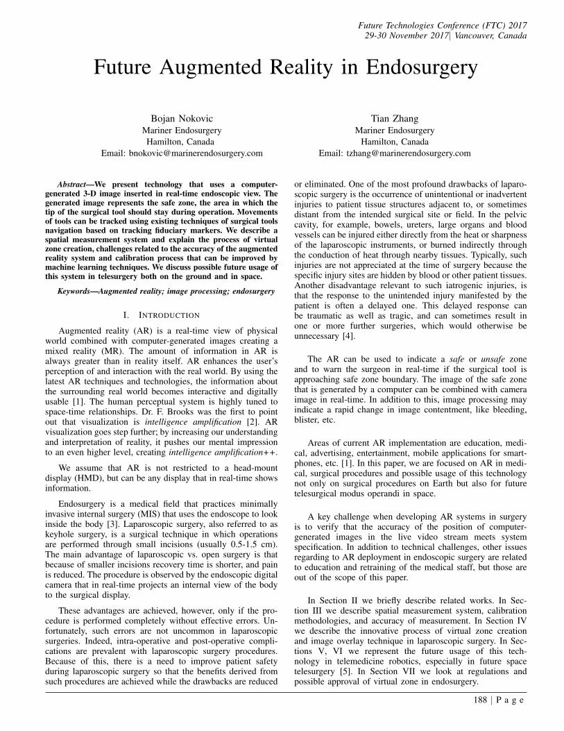
Fig. 1. Passive NDI polaris tool.
All aspects of the design, construction, and characterizationof tools used with NDI Polaris Systems [12] are describedin [13]. NDI is the producer of highly precise and robust3-D measurement tracking devices. The optical measurementsystem measures the 3-D positions of spherical markers. Theposition of the spherical markers determines the position ofthe surgical tools. Markers are used to track the tool duringIGS. The process of IGS combines spatial measurement withmedical imaging, typically CT or MRI. In standard IGSprocedure, images are registered with the patient’s position,and AR visualization of such structures is provided to thesurgeon [14].
A. Zone
The condition that must be satisfied during a surgicalprocedure can be represented as the 3-D structure called thesafe zone, an area in which surgical tools must be localizedduring the operation process. The safe zone can be createdby the surgeon or by surgical robot assistant, [15] by a toolsimilar to the one shown in Fig. 1. The area arbitrarily close tothe safe zone boundary is called the critical zone, it is 2-3 mminside the safe zone. The area outside of safe zone boundary(even if it is in camera view) is considered to be the unsafezone.
B. Tracking
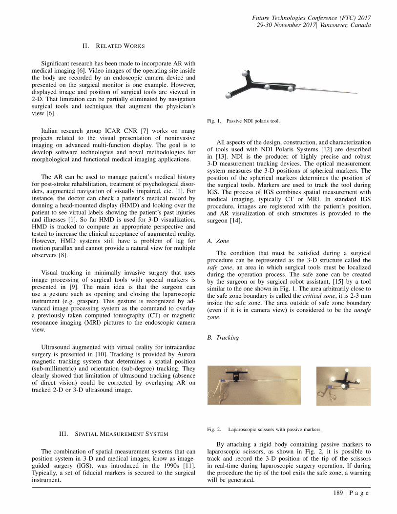
Fig. 2. Laparoscopic scissors with passive markers.
By attaching a rigid body containing passive markers tolaparoscopic scissors, as shown in Fig. 2, it is possible totrack and record the 3-D position of the tip of the scissorsin real-time during laparoscopic surgery operation. If duringthe procedure the tip of the tool exits the safe zone, a warningwill be generated.
189 | P a g e
Future Technologies Conference (FTC) 201729-30 November 2017| Vancouver, Canada
TABLE I. NDI TOOL ACCURACY [MM]
NDI 8700340Test # 3-D RMS Error Mean Err. Max 3-D Err.
1 0.32 0.29 0.562 0.39 0.35 0.803 0.40 0.36 0.84
TABLE II. SCISSORS WITH NDI RIGID BODY ACCURACY [MM]
Surgical Scissors with NDI RBTest # 3-D RMS Error Mean Err. Max 3-D Err.
1 0.54 0.47 1.482 0.53 0.47 1.393 0.52 0.47 1.30
C. Safe Zone Registration
Image registration is the process of overlaying images ofthe same scene taken from different viewpoints [16]. Registra-tion brings images into geometric alignments.
D. Accuracy
International Standard Organization (ISO) defines accuracyas the combination of trueness and precision [17], [18].Trueness is the difference between measured and true position.Precision is a measure of repeatability.
The accuracy of spatial measurement systems is usuallygiven as root-mean-square (RMS) distance error [11]. Thepositions measured by measurement system ~rm are comparedto reference position acquired by a coordinate measuringmachine (CMM) ~rr on a point by point basis. The RMSdetermined over the volume of N points is given by:
√√√√ 1
N
N∑i=1
(~rri − ~rmi)2 (1)
The overall volume RMS for NDI Polaris system is lessthan 0.35 mm for a single marker. We tested the rigid bodyshown in Fig. 1; the result is shown in Table I.
In next experiment, we tested the accuracy of the rigidbody attached to the surgical tool shown in Fig. 2. The resultis in Table II.
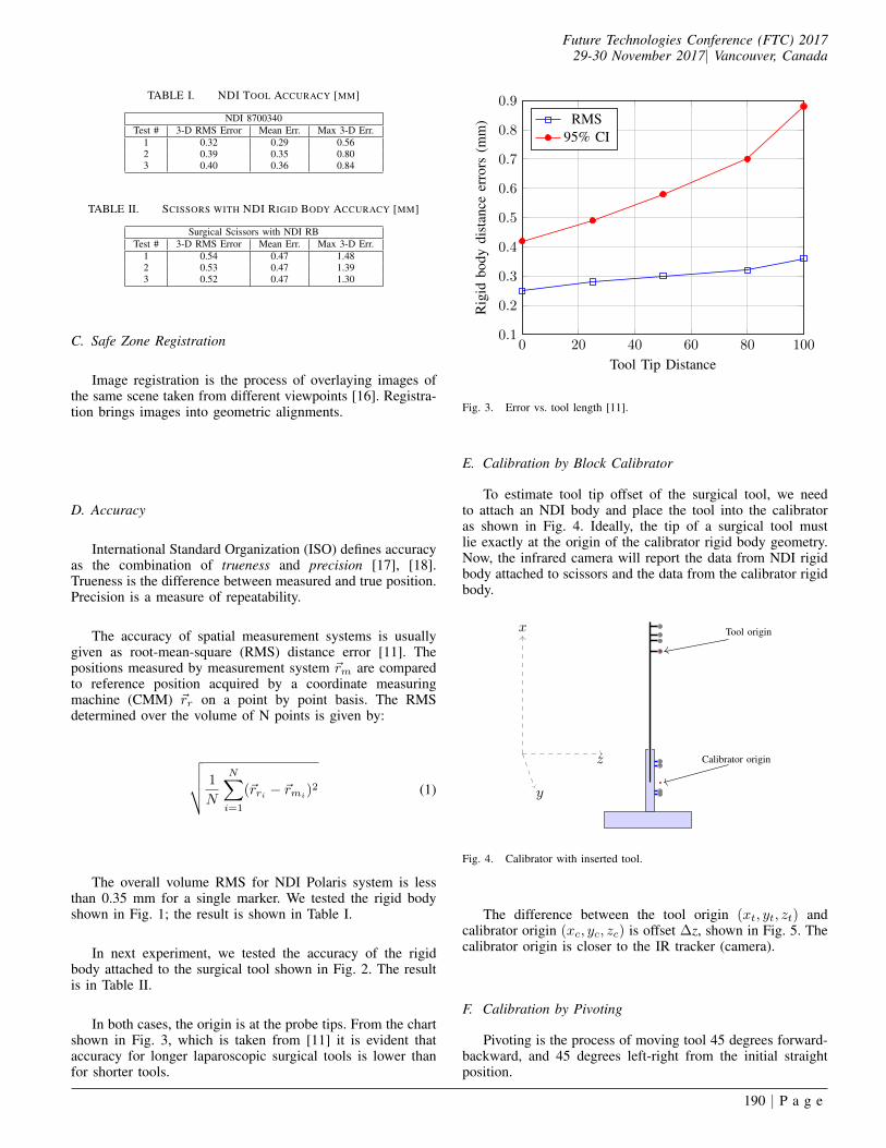
In both cases, the origin is at the probe tips. From the chartshown in Fig. 3, which is taken from [11] it is evident thataccuracy for longer laparoscopic surgical tools is lower thanfor shorter tools.
0 20 40 60 80 1000.1
0.2
0.3
0.4
0.5
0.6
0.7
0.8
0.9
Tool Tip Distance
Rig
idbo
dydi
stan
ceer
rors
(mm
) RMS95% CI
Fig. 3. Error vs. tool length [11].
E. Calibration by Block Calibrator
To estimate tool tip offset of the surgical tool, we needto attach an NDI body and place the tool into the calibratoras shown in Fig. 4. Ideally, the tip of a surgical tool mustlie exactly at the origin of the calibrator rigid body geometry.Now, the infrared camera will report the data from NDI rigidbody attached to scissors and the data from the calibrator rigidbody.
y
x
z
Tool origin
Calibrator origin
Fig. 4. Calibrator with inserted tool.
The difference between the tool origin (xt, yt, zt) andcalibrator origin (xc, yc, zc) is offset ∆z, shown in Fig. 5. Thecalibrator origin is closer to the IR tracker (camera).
F. Calibration by Pivoting
Pivoting is the process of moving tool 45 degrees forward-backward, and 45 degrees left-right from the initial straightposition.
190 | P a g e

Future Technologies Conference (FTC) 201729-30 November 2017| Vancouver, Canada
∆ z
y
x
z
Calibrator origin
Fig. 5. Calibrator sphere offset.
Fig. 6. Tool pivoting left-right and forward-backward.
The IR camera collects the position of the rigid toolbody and reports its origin at a rate of up to 60 frames persecond. The tool has to be moved from initial position to45 degrees forward, backward 90 degrees and back to theoriginal position. The movement must be completed in 10 sec.A similar movement is repeated going left-right-left. Duringthis process that lasts 20 sec., the camera reports about 1200positions that are distributed on the spherical surface; thecentre of the sphere is the pivoting point. We can use methodsimilar to one described by W.H. Beyer [19] to find the centerand radius of the sphere:
(xt − xc)2 + (yt − yc)2 + (zt − zc)2 = R.
(xt, yt, zt) is the reported origin of the tool, and (xp, yp, zp)position of the pivoting point. We need at least four origintool positions to determine the pivoting point or center of thesphere. For instance for reported positions (3,2,1), (1,-2,-3),(2,1,3), (-1,1,2)∣∣∣∣∣∣∣∣∣
x2t + y2
t + z2t xt yt zt 1
32 + 22 + 12 3 2 1 112 + (−2)2 + (−3)2 1 −2 −3 1
22 + 12 + 32 2 1 3 1(−1)2 + 12 + 22 −1 1 2 1
∣∣∣∣∣∣∣∣∣ = 0
Solving upper determinant we get
x2 + y2 + z2 − 48
19x+
32
19y − 8
19z = 0
(x− 24
19)2 + (y − 16
19)2 + (z − 4
19)2 =
4230
361
so the centre of the sphere is at
xc =24
19yc =
16
19zc =
4
19
θ
Tool
y
x
zControl Box
Fig. 7. Pivoting technique, tool tip in the centre of the ball.
If tool tip is sharp, the pivoting technique on the flatsurface shown in Fig. 6 and on the ball shown in Fig. 7have proximately the same accuracy. But in general whenthe tip of the tool is not sharp, pivoting on the ball is moreaccurate. During pivoting process about 1200 3-D positionsare collected. We can calculate(
1200
4
)=
1200!
4!(1200− 4)!≈ 86 billion
centres of the sphere. Such calibration would be time con-suming. Given that the calibration has to be done in 2-3 min,we need to extract the combination of points that gives usthe most accurate estimation. Those are points that have thelongest distance, taking into account that error in z-plane isgreater than in x and y [20]. This is a typical problem thatcan be solved by classification that is a core component ofmachine learning. When the set of ten combinations of fourpoints is selected, the centre of the sphere is calculated foreach of the ten combinations. The calibrated value is the RMSof the ten calculated approximations according to (1).
G. Tracking Accuracy
High spatial measurement system accuracy is crucial forimage-guided surgery. But accuracy assessment for systemstracking rigid bodies are ambiguous, and accuracy depends onmany factors, like the number of markers, position of the mark-ers to the camera, and external interference. The cornerstonerequirement for any measurement system remains whether itsaccuracy is sufficient for the intended application [11].
The general approach in accuracy analysis of a geometri-cal structure with fiducial markers registration accommodatesFiducial Localization Error (FLE), the distance between ameasured position and true position of a single marker. FLEcan be varying from point to point (inhomogeneous) and withthe direction (anisotropic) [21].
For the systems with several markers accuracy is describedby Fiducial Registration Error (FRE), that is the positioningerror of a rigid body (system with markers) after registration.Target Registration Error (TRE) is the positioning error ofany point of a tool excluding markers, most commonly thetool tip [17], as shown in Fig. 3.
191 | P a g e

Future Technologies Conference (FTC) 201729-30 November 2017| Vancouver, Canada
H. Overall System Accuracy
Image overlay error is about (3.5 mm ± 1.5 mm), butsystem accuracy is determined only by tool tracking precision.Tracking inside 3-D virtual zone has an RMS accuracy of 2.5mm.
I. Interference
The charge-coupled devices (CCDs) on the IR tracker aresensitive only to light in range 800 nm to 1.1mm (frequencyrange between 375 THz and 272 GHz) shown in Fig. 8 [22].
700 800 900 1,000 1,100 1,2000
10
20
30
40
50
60
70
80
90
100
Light Wavelength (nm)
Am
ount
oflig
htde
tect
edby
CC
Ds
(%)
Fig. 8. Filter spectral response.
If environmental light has a strong IR component, it mayinterfere to the system. Although some operating room lightsmay emit IR, typical surgical LED light spectra given at Fig. 9has reduced the IR component. Further reduction, if needed,is possible by special filters that can reduce IR component bymore than ten times, as shown in range from 700 nm to 900nm of Fig. 9. Detailed study how special films can be usedto reduce IR component of the illumination spectrum is givenin [23].
400 500 600 700 800 9000
10
20
30
40
50
60
70
80
90
100
Light Wavelength (nm)
Rel
ativ
ein
tens
ity(%
)
Fig. 9. Spectra of white LED surgical lamp.
IV. VIRTUAL ZONE CREATION
We propose the creation of 3-D virtual geometrical struc-ture by 3-D tracking tools on which fiducial markers areattached. The structure is created over the static scene. Thisapproach eliminates problems like occlusion detection and howto fill the holes on the reconstructed surfaces, as is typicallyseen in 3-D reconstruction based on feature tracking, metricreconstruction, and object insertion [24].
A. 3-D Zone Creation
IRTr
acke
r
Spherical markerswith retro-reflective
coating
Rigid bodytool
y
x
z
Fig. 10. Infrared flash and strong direct reflection.
Infrared Tracker sends flashlight to the geometrical struc-ture with attached retro-reflective spheres as shown in Fig. 10.The main reflection from spheres defines their absolute po-sition in the 3-D plane. A description of the number anddetermination of the location of spherical markers is generatedduring the tool characterization process in which the tooldefinition file is created. While tracking the rigid body, the IRcamera returns the location of the geometric center of spheres.The position is calculated taking into account relative positionsof each spherical marker to increase accuracy [11].
The position of tool tip, as shown in Fig. 11 can becalculated as a fixed offset from the rigid body origin. It isdetermined either by a block calibrator or pivoting procedureas described in [13].
Fig. 11. Virtual line created by tool movement from A to A′.
192 | P a g e
Future Technologies Conference (FTC) 201729-30 November 2017| Vancouver, Canada
When the tool moves form point A(x1, y1, z1) to point A′
(xN , yN , zN ), the camera reports the 3-D position of the tooltip points
(xi, yi, zi) i ∈ 1..N
The IR tracker reports 60 frames per second, so the tool tip canbe used as a pencil to draw virtual lines like the one betweenpoint A and A′ shown in Fig. 11.
In a similar way, we create the 3-D virtual conical structure.First, we point on the top of the structure, then to the bottomand after that drawing concentric circles go back to the upperpart of the structure as shown in Fig. 12. In MIS surgery, the tipof the canonical structure is the trocar entry point, the bottomof the structure is the operation position, and the structurecreated by concentric circles is operation safe zone.
Entry point
Operation target
y
x
z
Fig. 12. Virtual 3-D zone.
B. Synthesis of Real Environments with Virtual Objects
Methods of virtual view generation can be classified intotwo categories: In the first, a full 3-D view of the scene isconstructed and then reprojected to generate the virtual view. Inthe second method, virtual views are directly generated withouthaving to estimate the scene structure [24].
Endoscopic camera position and orientation about a targetobject is determined by the position of the attached fiducialmarkers. We assume that the camera does not change itsmagnification. The virtual object should be inserted to targetposition according to camera position and orientation. Whencamera pose is changed, the position of virtual object 3-D zonemust be changed too.
Surgical tool
y
x
z
Fig. 13. Virtual 3-D zone with guidance data and distance to safe zoneboundary indication.
Additional guidance of a tool to a target as shown in Fig. 13is integrated. It handles the loss of depth perception related tothe overlay of virtual models and endoscopic images [25].
The guidance provides information on a projected trajec-tory line, target and a depth bar that indicates the distance fromthe tip of the surgical tool, to the target.
Distance to the safe zone boundary shows in real-time thedistance from the tip of the surgical tool to the safe zone edge.
A rigid tool with retro-reflective spheres can be attached toany laparoscopic surgical tool and used to show the positionof the tooltip tracked during the operation. While the tool tipis inside the 3-D virtual safe zone, the operation is consideredto be safe; when tool tip exits the virtual safe zone, an alarmwarns the surgeon that the tool is not in the safe area.
This is different than existing systems of visual featuretracking [9], in which a process of intensive signal processingis used to indicate the position of tool tip inside the body.While both techniques are emerging, we believe that themethod that embeds a virtual 3-D zone into the real-timestream is more promising because of ability to record surgicaltools movements more accurately. That allows recording ofa 3-D positions of any surgical instrument tip during theprocedure. The record may be used to track possible inaccuracyin the process and to evaluate surgical skills quantitatively.
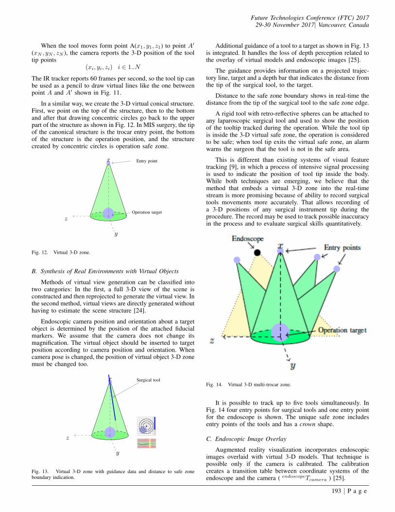
Fig. 14. Virtual 3-D multi-trocar zone.
It is possible to track up to five tools simultaneously. InFig. 14 four entry points for surgical tools and one entry pointfor the endoscope is shown. The unique safe zone includesentry points of the tools and has a crown shape.
C. Endoscopic Image Overlay
Augmented reality visualization incorporates endoscopicimages overlaid with virtual 3-D models. That technique ispossible only if the camera is calibrated. The calibrationcreates a transition table between coordinate systems of theendoscope and the camera ( endoscopeTcamera ) [25].
193 | P a g e
Future Technologies Conference (FTC) 201729-30 November 2017| Vancouver, Canada
IR tracker
(trackerTendoscope)
Endoscope
(trackerTcheckboard)
(cameraTcheckboard)
Fig. 15. Coordinate translation.
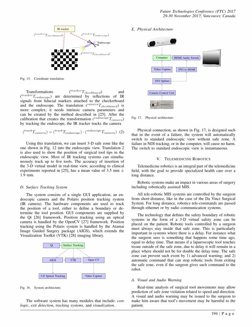
Transformations (trackerTcheckboard) and(trackerTendoscope) are determined by reflections of IRsignals from fiducial markers attached to the checkerboardand the endoscope. The translation (cameraTcheckboard) ismore complex; it needs intrinsic camera parameters andcan be created by the method described in [25]. After thecalibration that creates the transformation (endoscopeTcamera)by tracking the endoscope, the IR tracker tracks the camera
(trackTcamera) = (trackTendoscope) · (endoscopeTcamera) (2)
Using this translation, we can insert 3-D safe zone like theone shown in Fig. 12 into the endoscopic view. Translation 2is also used to show the position of surgical tool tips in theendoscopic view. Most of IR tracking systems can simulta-neously track up to five tools. The accuracy of insertion ofthe 3-D virtual model in real-time view, according to clinicalexperiments reported in [25], has a mean value of 3.5 mm ±1.9 mm.
D. Surface Tracking System
The system consists of a single GUI application, an en-doscopic camera and the Polaris position tracking system(IR camera). The hardware components are used to trackthe position of a tool, either to define a boundary or de-termine the tool position. GUI components are supplied bythe Qt [26] framework. Position tracking using an opticalcamera is handled by the OpenCV [27] framework. Positiontracking using the Polaris system is handled by the AtamaiImage Guided Surgery package (AIGS), which extends theVisualization Toolkit (VTK) [28] imaging library.
Qt Surface Tracking
Open CVVTKAIGS
3-D Spatial Tracking Video Capture
Fig. 16. System architecture.
The software system has many modules that include: corelogic, exit detection, tracking systems, and visualization.
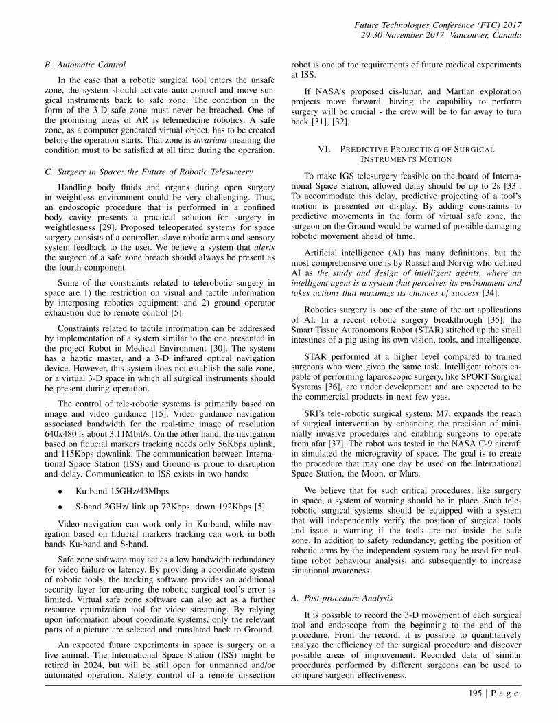
E. Physical Architecture
Computer HDMI Audio Switch
Video Capture DVI to HDMI
DVI Splitter
Camera Control Unit
Fig. 17. Physical architecture.
Physical connection, as shown in Fig. 17, is designed suchthat in the event of a failure, the system will automaticallyswitch to standard endoscopic view without safe zone. Afailure in NDI tracking, or in the computer, will cause no harm.The switch to standard endoscopic view is instantaneous.
V. TELEMEDICINE ROBOTICS
Telemedicine robotics is an integral part of the telemedicinefield, with the goal to provide specialized health care over along distance.
Robotic systems make an impact in various areas of surgeryincluding robotically assisted MIS.
All tele-robotic MIS systems are controlled by the surgeonfrom short-distance, like in the case of the Da Vinci SurgicalSystem. For long distance, robotics tele-commands are passedthrough ethernet or by radio communication systems.
The technology that defines the safety boundary of roboticsystems in the form of a 3-D virtual safety zone can beplaced on the patient. Robotic tools controlled by a surgeonmust always stay inside that safe zone. This is particularlyimportant in systems where there is a delay. For instance whatthe surgeon sees is something that happens some time ago,equal to delay time. That means if a laparoscopic tool touchestissue outside of the safe zone, due to delay it will remain in aplace where should not be for double the delay time. The safezone can prevent such event by 1) advanced warning; and 2)automatic command that can stop robotic tools from exitingthe safe zone, even if the surgeon gives such command to therobot.
A. Visual and Audio Warning
Real-time analysis of surgical tool movements may allowprediction of safe zone violation related to speed and direction.A visual and audio warning may be issued to the surgeon tomake him aware that tool’s movement may be harmful to thepatient.
194 | P a g e
Future Technologies Conference (FTC) 201729-30 November 2017| Vancouver, Canada
B. Automatic Control
In the case that a robotic surgical tool enters the unsafezone, the system should activate auto-control and move sur-gical instruments back to safe zone. The condition in theform of the 3-D safe zone must never be breached. One ofthe promising areas of AR is telemedicine robotics. A safezone, as a computer generated virtual object, has to be createdbefore the operation starts. That zone is invariant meaning thecondition must to be satisfied at all time during the operation.
C. Surgery in Space: the Future of Robotic Telesurgery
Handling body fluids and organs during open surgeryin weightless environment could be very challenging. Thus,an endoscopic procedure that is performed in a confinedbody cavity presents a practical solution for surgery inweightlesness [29]. Proposed teleoperated systems for spacesurgery consists of a controller, slave robotic arms and sensorysystem feedback to the user. We believe a system that alertsthe surgeon of a safe zone breach should always be present asthe fourth component.
Some of the constraints related to telerobotic surgery inspace are 1) the restriction on visual and tactile informationby interposing robotics equipment; and 2) ground operatorexhaustion due to remote control [5].
Constraints related to tactile information can be addressedby implementation of a system similar to the one presented inthe project Robot in Medical Environment [30]. The systemhas a haptic master, and a 3-D infrared optical navigationdevice. However, this system does not establish the safe zone,or a virtual 3-D space in which all surgical instruments shouldbe present during operation.
The control of tele-robotic systems is primarily based onimage and video guidance [15]. Video guidance navigationassociated bandwidth for the real-time image of resolution640x480 is about 3.11Mbit/s. On the other hand, the navigationbased on fiducial markers tracking needs only 56Kbps uplink,and 115Kbps downlink. The communication between Interna-tional Space Station (ISS) and Ground is prone to disruptionand delay. Communication to ISS exists in two bands:
• Ku-band 15GHz/43Mbps
• S-band 2GHz/ link up 72Kbps, down 192Kbps [5].
Video navigation can work only in Ku-band, while nav-igation based on fiducial markers tracking can work in bothbands Ku-band and S-band.
Safe zone software may act as a low bandwidth redundancyfor video failure or latency. By providing a coordinate systemof robotic tools, the tracking software provides an additionalsecurity layer for ensuring the robotic surgical tool’s error islimited. Virtual safe zone software can also act as a furtherresource optimization tool for video streaming. By relyingupon information about coordinate systems, only the relevantparts of a picture are selected and translated back to Ground.
An expected future experiments in space is surgery on alive animal. The International Space Station (ISS) might beretired in 2024, but will be still open for unmanned and/orautomated operation. Safety control of a remote dissection
robot is one of the requirements of future medical experimentsat ISS.
If NASA’s proposed cis-lunar, and Martian explorationprojects move forward, having the capability to performsurgery will be crucial - the crew will be to far away to turnback [31], [32].
VI. PREDICTIVE PROJECTING OF SURGICALINSTRUMENTS MOTION
To make IGS telesurgery feasible on the board of Interna-tional Space Station, allowed delay should be up to 2s [33].To accommodate this delay, predictive projecting of a tool’smotion is presented on display. By adding constraints topredictive movements in the form of virtual safe zone, thesurgeon on the Ground would be warned of possible damagingrobotic movement ahead of time.
Artificial intelligence (AI) has many definitions, but themost comprehensive one is by Russel and Norvig who definedAI as the study and design of intelligent agents, where anintelligent agent is a system that perceives its environment andtakes actions that maximize its chances of success [34].
Robotics surgery is one of the state of the art applicationsof AI. In a recent robotic surgery breakthrough [35], theSmart Tissue Autonomous Robot (STAR) stitched up the smallintestines of a pig using its own vision, tools, and intelligence.
STAR performed at a higher level compared to trainedsurgeons who were given the same task. Intelligent robots ca-pable of performing laparoscopic surgery, like SPORT SurgicalSystems [36], are under development and are expected to bethe commercial products in next few yeas.
SRI’s tele-robotic surgical system, M7, expands the reachof surgical intervention by enhancing the precision of mini-mally invasive procedures and enabling surgeons to operatefrom afar [37]. The robot was tested in the NASA C-9 aircraftin simulated the microgravity of space. The goal is to createthe procedure that may one day be used on the InternationalSpace Station, the Moon, or Mars.
We believe that for such critical procedures, like surgeryin space, a system of warning should be in place. Such tele-robotic surgical systems should be equipped with a systemthat will independently verify the position of surgical toolsand issue a warning if the tools are not inside the safezone. In addition to safety redundancy, getting the position ofrobotic arms by the independent system may be used for real-time robot behaviour analysis, and subsequently to increasesituational awareness.
A. Post-procedure Analysis
It is possible to record the 3-D movement of each surgicaltool and endoscope from the beginning to the end of theprocedure. From the record, it is possible to quantitativelyanalyze the efficiency of the surgical procedure and discoverpossible areas of improvement. Recorded data of similarprocedures performed by different surgeons can be used tocompare surgeon effectiveness.
195 | P a g e

Future Technologies Conference (FTC) 201729-30 November 2017| Vancouver, Canada
VII. REGULATIONS
Medical devices are classified into Class I, II, and III andregulatory control increases from Class I to Class III [38]. Webelieve that most of these navigation technologies, includingrobotics, are Class II devices (moderate to high risk) to theFDA.
The augmented reality offers an additional feature; anoption for the surgeon to disable it at any moment during asurgical procedure. A software watchdog controls the AR, so ifthere is any problem, the system automatically switches backto the non-augmented mode. Because of this, we believe therisk of AR usage is even lower than moderate, and can therebyspeed up the regulatory approval process.
VIII. CONCLUSION
Development in computer vision and robotics are alreadychanging the way in which surgery is being practiced [14].AR in endosurgery is an emerging interdisciplinary field withpotentially great impact on surgical procedures. The combina-tion of pre-generated visual objects, real-time video streamingand real-time computer generated objects acquired by opticalmeasurement systems in endosurgery is an example of a pos-sible AR application in surgery. In addition to this, increasingcomputing power allows real-time image recognition that mayprovide additional information for the surgeon during thesurgical procedure. The surgical tool tip movement inside thebody can be recorded and quantitatively analyzed in the post-surgical process.
This procedure can increase the efficiency of laparoscopicsurgery and estimate potential risks by calculating smoothiesand speed of surgical tools during the procedure vs. distanceto the safe zone boundary.
We believe that this system is also applicable in roboticassisted surgery: the position of the surgical tool held by therobotic arm can be verified in real-time by precise and accurateoptical system. This technique may be especially useful inemerging field of space telesurgery.
ACKNOWLEDGMENT
The authors thank Mitch Wilson and Ashlin Kanawatyfrom Mariner Endosurgery Inc. for their help and comments.
REFERENCES
[1] B. Furht, Handbook of Augmented Reality. Springer PublishingCompany, Incorporated, 2011.
[2] F. P. Brooks, Jr., “The Computer Scientist As Toolsmith II,” Commun.ACM, vol. 39, no. 3, pp. 61–68, Mar. 1996. [Online]. Available:http://doi.acm.org/10.1145/227234.227243
[3] T. Smith and B. M. Association, The British Medical Association Com-plete Family Health Encyclopedia. Dorling Kindersley, 1995. [Online].Available: https://books.google.ca/books?id=6Y8QAAAACAAJ
[4] B. Nokovic, M. Wilson, and N. Nedialkov, “Laparoscopic SurgerySystem Calibrator and Method for Using the Same,” 2016, Provisionalpatent US 62/439,845.
[5] JAXA, “Japan Aerospace Exploration Agency,” 2017, http://global.jaxa.jp/.
[6] C. Bichlmeier, F. Wimmer, S. M. Heining, and N. Navab, “ContextualAnatomic Mimesis Hybrid In-Situ Visualization Method for ImprovingMulti-Sensory Depth Perception in Medical Augmented Reality,” in2007 6th IEEE and ACM International Symposium on Mixed andAugmented Reality, Nov 2007, pp. 129–138.
[7] L. di Calcolo e Reti ad Alte Prestazioni del Consiglio Nazionale delleRicerche, “Non Invasive Imaging For Advanced M.F.D.” 2017, http://www.icar.cnr.it/en.
[8] H. Liao, 3D Medical Imaging and Augmented Reality for Image-GuidedSurgery. New York, NY: Springer New York, 2011, pp. 589–602.[Online]. Available: http://dx.doi.org/10.1007/978-1-4614-0064-6 27
[9] S. Payandeh, Visual Tracking in Conventional Minimally InvasiveSurgery. Chapman and Hall/CRC, 2016.
[10] D. Bainbridge, D. L. Jones, G. M. Guiraudon, and T. M.Peters, “Ultrasound Image and Augmented Reality Guidance forOff-pump, Closed, Beating, Intracardiac Surgery,” Artificial Organs,vol. 32, no. 11, pp. 840–845, 2008. [Online]. Available: http://dx.doi.org/10.1111/j.1525-1594.2008.00639.x
[11] Accuracy assessment and interpretation for optical tracking systems,vol. 5367, 2004. [Online]. Available: http://dx.doi.org/10.1117/12.536128
[12] NDI, “3D Measurement Tracking Technology,” 2016, http://www.ndigital.com/.
[13] NDI, “Polaris tool digital design,” 2007.[14] W. Grimson, R. Kikinis, F. A. Jolesz, and P. Black, “Image-guided
surgery,” Scientific American, vol. 280, no. 6, pp. 54–61, 1999.[15] S. Avgousti, E. G. Christoforou, A. S. Panayides, S. Voskarides,
C. Novales, L. Nouaille, C. S. Pattichis, and P. Vieyres, “MedicalTelerobotic Systems: Current Status and Future Trends,” in Biomedicalengineering online, 2016.
[16] B. Zitov and J. Flusser, “Image registration methods: a survey,” IMAGEAND VISION COMPUTING, vol. 21, pp. 977–1000, 2003.
[17] R. Elfring, M. de la Fuente, and K. Radermacher, Accuracy ofOptical Localizers for Computer Aided Surgery. Berlin, Heidelberg:Springer Berlin Heidelberg, 2009, pp. 328–330. [Online]. Available:http://dx.doi.org/10.1007/978-3-642-03906-5 90
[18] ISO, “Accuracy (trueness and precision) of measurement methods andresults. Part 1: General principles and definitions,” 1994.
[19] W. Beyer, CRC Standard Mathematical Tables: 28th Ed. CRCPress, 1987. [Online]. Available: https://books.google.ca/books?id=hEueMgEACAAJ
[20] A. D. Wiles, A. Likholyot, D. D. Frantz, and T. M. Peters,“A Statistical Model for Point-Based Target Registration ErrorWith Anisotropic Fiducial Localizer Error.” IEEE Trans. Med.Imaging, vol. 27, no. 3, pp. 378–390, 2008. [Online]. Available:http://dblp.uni-trier.de/db/journals/tmi/tmi27.html#WilesLFP08
[21] A. Danilchenko and J. M. Fitzpatrick, “General Approach to First-OrderError Prediction in Rigid Point Registration,” IEEE Transactions onMedical Imaging, vol. 30, no. 3, pp. 679–693, March 2011.
[22] NDI, “Passive Polaris Spectra user guide - Revision 7,” 2012.[23] N. Zhu, S. Mondal, S. Gao, S. Achilefu, V. Gruev, and R. Liang,
“Engineering light-emitting diode surgical light for near-infraredfluorescence image-guided surgical systems,” Journal of BiomedicalOptics, vol. 19, no. 7, p. 076018, 2014. [Online]. Available:http://dx.doi.org/10.1117/1.JBO.19.7.076018
[24] J.-S. Park, M. Y. Sung, and S.-R. Noh, Virtual Object Placement inVideo for Augmented Reality. Berlin, Heidelberg: Springer BerlinHeidelberg, 2005, pp. 13–24.
[25] M. Fusaglia, K. Gavaghan, G. Beldi, F. Volonte, F. Pugin, M. Peterhans,N. Buchs, and S. Weber, Endoscopic Image Overlay for the Targetingof Hidden Anatomy in Laparoscopic Visceral Surgery. Berlin,Heidelberg: Springer Berlin Heidelberg, 2013, pp. 9–21. [Online].Available: http://dx.doi.org/10.1007/978-3-642-38085-3 3
[26] T. Q. Company, “Cross-platform application framework,” 2017, https://www.qt.io/.
[27] O. Foundation, “Open Source Computer Vision Library,” 2017, http://opencv.org/.
[28] K. Inc., “The visualization toolkit,” 2017, http://www.vtk.org/.[29] T. Haidegger, J. Sandor, and Z. Benyo, “Surgery in space: the
future of robotic telesurgery,” Surgical Endoscopy, vol. 25, no. 3,pp. 681–690, 2011. [Online]. Available: http://dx.doi.org/10.1007/s00464-010-1243-3
196 | P a g e

Future Technologies Conference (FTC) 201729-30 November 2017| Vancouver, Canada
[30] A. Rossi, A. Trevisani, and V. Zanotto, “A telerobotic haptic system forminimally invasive stereotactic neurosurgery,” The International Journalof Medical Robotics and Computer Assisted Surgery, vol. 1, no. 2, pp.64–75, 2005. [Online]. Available: http://dx.doi.org/10.1002/rcs.17
[31] Spacenews, “Nasa moving ahead with plans for cis-lunar human outpost,” 2017, http://spacenews.com/nasa-moving-ahead-with-plans-for-cislunar-human-outpost/.
[32] NASA, “Prepare for the human exploration of mars,” 2017, https://mars.nasa.gov/programmissions/science/goal4/.
[33] I. Mendez, R. Hill, D. Clarke, G. Kolyvas, and S. Walling, “RoboticLong-distance Telementoring in Neurosurgery,” Neurosurgery, vol. 56,
pp. 434–440, 2005.[34] S. J. Russell and P. Norvig, Artificial Intelligence: A Modern Approach,
2nd ed. Pearson Education, 2003.[35] E. Strickland, “Autonomous Robot Surgeon Bests Humans in World
First,” 2017, http://spectrum.ieee.org.[36] T. Medical, “SPORT Surgical System,” 2017, http://www.
titanmedicalinc.com/.[37] S. International, “M7 Surgical Robot,” 2017, https://www.sri.com/.[38] FDA, “Classification of medical devices,” 2017, https://www.fda.gov/.
197 | P a g e