iwaki electromagnetic metering pump492-2)_english.pdf · read this manual before use of product...
TRANSCRIPT

Read this manual before use of product
IWAKIElectromagnetic Metering PumpEW-Y SeriesInstruction Manual
T492-2 '07/10
IWAKI CO.,LTD. 6-6 Kanda-Sudacho 2-chome Chiyoda-ku Tokyo 101-8558 JapanTEL:(81)3 3254 2935 FAX:3 3252 8892(http://www.iwakipumps.jp)
U.S.A. : IWAKI America Inc.Australia : IWAKI Pumps Australia Pty. Ltd.Singapore : IWAKI Singapore Pte. Ltd.Indonesia : IWAKI Singapore (Indonesia Branch)Malaysia : IWAKIm Sdn. Bhd.Taiwan : IWAKI Pumps Taiwan Co., Ltd.Thailand : IWAKI (Thailand) Co.,Ltd.Hong Kong : IWAKI Pumps Co., Ltd.China : GFTZ IWAKI Engineering & Trading Co., Ltd.China : IWAKI Pumps Co., Ltd. (Beijing office)China : IWAKI Pumps (Shanghai) Co., Ltd.Philippines : IWAKI Chemical Pumps Philippines, Inc.Korea : IWAKI Korea Co.,Ltd.Vietnam : IWAKI Pumps Vietnam Joint Venture Co.,Ltd.
TEL : (1)508 429 1440 FAX : 508 429 1386TEL : (61)2 9899 2411 FAX : 2 9899 2421TEL : (65)763 2744 FAX : 763 2372TEL : (62)21 690 6607 FAX : 21 690 6612TEL : (60)3 7803 8807 FAX : 3 7803 4800TEL : (886)2 8227 6900 FAX : 2 8227 6818TEL : (66)2 320 1303 FAX : 2 322 2477TEL : (852)2 607 1168 FAX : 2 607 1000TEL : (86)20 8435 0603 FAX : 20 8435 9181TEL : (86)10 6442 7713 FAX : 10 6442 7712TEL : (86)21 6272 7502 FAX : 21 6272 6929TEL : (63)2 888 0245 FAX : 2 843 3096TEL : (82)2 3474 0523 FAX : 2 3474 0221TEL : (84)613 933456 FAX : 613 933399
Germany : IWAKI EUROPE GmbHItaly : IWAKI Italia S.R.L.Denmark : IWAKI Pumper A/SSweden : IWAKI Sverige ABFinland : IWAKI Suomi OyNorway : IWAKI Norge ASFrance : IWAKI France S.A.U.K. : IWAKI PUMPS (UK) LTD.Switzerland : IWAKI (Schweiz) AGAustria : IWAKI (Austria) GmbHHolland : IWAKI Holland B.V.Spain : IWAKI Iberica Pumps, S.A.Belgium : IWAKI Belgium n.v.
TEL : (49)2154 9254 0 FAX : 2154 1028TEL : (39)02 990 3931 FAX : 02 990 42888TEL : (45)48 24 2345 FAX : 48 24 2346TEL : (46)8 511 72900 FAX : 8 511 72922TEL : (358)9 2742714 FAX : 9 2742715TEL : (47)66 81 16 60 FAX : 66 81 16 61TEL : (33)1 69 63 33 70 FAX : 1 64 49 92 73TEL : (44)1743 231363 FAX : 1743 366507TEL : (41)32 3235024 FAX : 32 3226084TEL : (43)2236 33469 FAX : 2236 33469TEL : (31)297 241121 FAX : 297 273902TEL : (34)943 630030 FAX : 943 628799TEL : (32)1430 7007 FAX : 1430 7008

ContentsIMPORTANT INSTRUCTION . . . . . . . . . . . . . . . . . . . . . . . . . . . . . . . . . . . . . . . . . . . . . . . . . . . . . . . 1Safety Instructions . . . . . . . . . . . . . . . . . . . . . . . . . . . . . . . . . . . . . . . . . . . . . . . . . . . . . . . . . . . . . . . . . . . . . . . . 2
Outline . . . . . . . . . . . . . . . . . . . . . . . . . . . . . . . . . . . . . . . . . . . . . . . . . . . . . . . . . . . . . . . . . . . . . . . . . . . . . . . . . . . . . . . 5 1. Unpacking & Inspection . . . . . . . . . . . . . . . . . . . . . . . . . . . 6 2. Operation Principle . . . . . . . . . . . . . . . . . . . . . . . . . . . . . . . . . . 6 3. Identification Codes . . . . . . . . . . . . . . . . . . . . . . . . . . . . . . . . . 7 4. Specifications . . . . . . . . . . . . . . . . . . . . . . . . . . . . . . . . . . . . . . . . . . 8 5. External Dimensions . . . . . . . . . . . . . . . . . . . . . . . . . . . . . . 11 6. Main Parts & Label . . . . . . . . . . . . . . . . . . . . . . . . . . . . . . . . 15
Installation . . . . . . . . . . . . . . . . . . . . . . . . . . . . . . . . . . . . . . . . . . . . . . . . . . . . . . . . . . . . . . . . . . . . . . . . . . . . . . . . . . 16 1. Before Use . . . . . . . . . . . . . . . . . . . . . . . . . . . . . . . . . . . . . . . . . . . . 17 2. Notes on Operation . . . . . . . . . . . . . . . . . . . . . . . . . . . . . . . . 17 3. Installation, Piping, & Wiring . . . . . . . . . . . . . . . . . . . 20
Operation . . . . . . . . . . . . . . . . . . . . . . . . . . . . . . . . . . . . . . . . . . . . . . . . . . . . . . . . . . . . . . . . . . . . . . . . . . . . . . . . . . . 27 1. Bleeding . . . . . . . . . . . . . . . . . . . . . . . . . . . . . . . . . . . . . . . . . . . . . . . . 28 2. Flow rate Adjustment . . . . . . . . . . . . . . . . . . . . . . . . . . . . . 30 3. Operation . . . . . . . . . . . . . . . . . . . . . . . . . . . . . . . . . . . . . . . . . . . . . . 32
Maintenance . . . . . . . . . . . . . . . . . . . . . . . . . . . . . . . . . . . . . . . . . . . . . . . . . . . . . . . . . . . . . . . . . . . . . . . . . . . . . . . 53 1. Causes of Trouble & Troubleshooting . . . . . . . . . . . . . . . . . . . . . . . . . . . . . . . . . . . . . 54 2. Maintenance & Inspection . . . . . . . . . . . . . . . . . . . . . . 56 3. Disassembly & Reassembly . . . . . . . . . . . . . . . . . . . 57 4. Accessories . . . . . . . . . . . . . . . . . . . . . . . . . . . . . . . . . . . . . . . . . . . 61 5. Names of Parts & Structure . . . . . . . . . . . . . . . . . . . 62
This instruction manual should be kept on hand by the end user for quick reference. It is recommended that each user, after reading the instruction manual thoroughly, place it in a position close to the pump system and where it may be easily accessed by any user at any time whenever necessary.
Thank you for selecting the electromagnetic metering pump EW-Y series. This instruction
manual deals with “Safety Section” “Product outline” “Installation Section” “Operation
Section” and “Maintenance Section”.
Please read through this manual carefully to ensure the optimum performance, safety and
service of the EK series.

- 1 -
Nonobservance or misapplication of the contents of the “Caution” section could lead to the personal injury to users or serious damage to the product.
For the Safe and Correct Handling of the Pump
● "Safety Instruction" section mentions important details about the handling of the product. Before the use of pump, read this section carefully for the prevention of personnel injury or loss.
● Observe the instructions accompanied with "WARNING" or "CAUTION" in this manual. These instructions are very important for protecting pump users from the dangerous situations.
● The symbols on this instruction manual have the following meanings:
WARNINGNonobservance or misapplication of the contents of the “Warning” section could lead to a serious acci-dent which may result in death.
CAUTION
Types of Symbols
Indicates that “Warning” or “Caution” must be exercised. Inside this triangle, a con-crete and practical image provided as a warning or caution message is depicted.
Indicates a prohibited action or procedure. Inside or near this circle, a concrete and practical image of the activity to be avoided is depicted.
Indicates an important action or procedure which must be performed or carried out without fail. Failure to follow the instructions herein can lead to malfunction or damage to the pump.
Important Instructions

- 2 -
WARNING• Turn off the power supply
Working without disconnecting the power supply may cause an electrical shock. Before engaging upon any working procedures involving the pump, make sure to turn the power supply switch off and to stop the pump and other related devices.
• Terminate operation When you detect or become aware of a dangerous sign or abnormal condition during operation, terminate the operation immediately and start it from the beginning again.
• For specified application only The use of a pump in any application other than those clearly specified may result in injury or damage to the pump. Use the pump strictly in accordance with the pump specifications and application range.
• No remodeling Never remodel a pump. Otherwise, a serious accident may result. Iwaki will not be responsible for any accident or damage of any kind which is caused by the user remodeling the pump without first obtaining permission or instructions from Iwaki.
• Wear protectors If you touch or come in contact with any type of hazardous chemical liquid, including but not limited to chemicals, you may experience a serious injury. Wear protective gear (protective mask, gloves, etc.) during the pump operation.
• Operating site must be free of water and humidity The pump is not designed to be water-proof or dust-proof. The use of the pump in places where water splashes or humidity is high may result in an electrical shock or short circuit.
CAUTION• Qualified operators only
The pump operator and pump operation supervisor must not allow any operators who have little or no knowledge of the pump to run operate the pump. Pump operators must have a sound knowledge of the pump and its operation.
• Specified power only Do not operate the pump on voltage which is not specified on the nameplate. Failure to do so may result in damage or fire. Only the specified power level is to be applied.
Wear protective gear
Electrical Shock
Prohibited
Prohibited
No Remodeling
Prohibited
Prohibited
Safety instructions

- 3 -
CAUTION• Do not run the pump dry
Do not run the pump dry (without liquid inside the pump). Heat generated as a result of abrasion between elements inside the pump during operation without liquid may damage the inside of the pump.
• Do not wet or dampen If an electric part or wiring gets wet with the liquid spilled over accidentally, a fire or electrical shock may be caused. Install the system in a place free from liquid spillage or leakage.
• Ventilate Poisoning may result during an operation which involves toxic or odorous liquid. Ventilate the operating site sufficiently.
• Spill-out accident Protective measures should be taken against any accidental spill-out or leakage of the operating liquid as a result of unexpected damage on the pump or the related pip-ing.
• Damaged pump Never operate a damaged pump. A damaged pump may cause leakage or electrical shock.
• Do not damage power cable Do not scratch, damage, process, or pull the power cable forcibly. An extra load onto the cable, such as heating the cable or placing something heavy on the cable, may damage the cable and finally cause a fire or an electrical shock.
• Arrange grounding Do not operate the pump without connecting the grounding wire. Otherwise, an elec-trical shock may result. Make sure the grounding wire is connected with the grounding terminal.
• Install an earth leakage breaker The operation of a pump without using an earth leakage breaker may cause an elec-trical shock. Please install an optional leakage breaker in the system.
• Handling of power cable Use of a defective or damaged power cable may result in a fire or electrical shock. Handle the power cable carefully.
Electrical Shock
Electrical Shock
Prohibited
Prohibited
Caution
Caution
Caution
Do not wet or dampen
Grounding
Safety instructions

- 4 -
CAUTION• Follow the instruction manual
Replace the consumable parts by following the descriptions in the instruction manual. Do not disassemble any part of the pump if the disassembling procedure for the part in question is not included in the instruction manual.
• Limited operating site and storageDo not install or store the pump in the following places:* Places where a flammable gas or material is used or stored.* Places where the ambient temperature is extremely high (40°C or higher) or
extremely low (0°C or lower).
• Disposal of used pump Disposal of used or damaged pumps must be done in accordance with the relevant local laws and regulations. (Consult a licensed industrial waste products disposing company.)
• Frequent stop and start of pump should be done by using STOP function (ON and OFF of STOP terminal). If you can not use STOP function and are forced to operate pump by turning OFF and ON of power source, ON and OFF of power source should be limited to six times an hour.
Prohibited
Safety instructions

- 5 -
1.Unpacking & Inspection ........................ 6
2.Operation Principle .............................. 6
3.Identification Codes ............................. 7
4.Specifications ........................................ 8
5.External Dimensions ........................... 11
6.Main Parts & Label ............................. 15
Outline

- 6 -
After unpacking the pump, check the following points to ascertain that the product is exactly as you ordered. If you find anything wrong, please get in touch with your dealer.
[1] Do the model, discharge pressure, voltage, etc., shown on the nameplate represent what you ordered?
[2] Has the pump been damaged in transit? Are the bolts and nuts loose?
The Iwaki EW-Y series electromagnetic pump is a diaphragm metering pump of the 'linear electromagnetic drive system', which means electromagnetic force drives the diaphragm directly. It consists of a pump unit, a drive unit and a control unit. Reciprocating movement is caused by the electromagnetic force produced by the pulse current sent from the control unit, and the force of a spring. The reciprocating movement is transmitted to the diaphragm directly connected to a plunger, to change the capacity of the pump chamber. The changed capacity and the functioning of the valves in the pump unit drive the pump.
Outline1.Unpacking & Inspection
2.Operation Principle

- 7 -
3.Identification Codes• Pump Identification
EW - F 11 VC - 20E P Y 2 (1) (2) (3) (4) (5) (6) (7) (8) (9)
(1) Series code
(2) Drive unit type
(3) Diaphragm diameter
(4) Wet end material
(5) Material PVC : Transparent polyvinyl chloride GFRPP: Glassfiber reinforced polypropylene CE: Alumina Ceramic HC: Hastelloy C 276 FKM: Fluoroelastomer EPDM: Ethylene propylene diene methylene PTFE: Polytetrafluoroethylene SUS316: Austenite stainless steel PVDF: Polyvinylidenefluoride (6) Power source voltage
Code Pump head Valve Valve seat Diaphragm GasketVC
PVCCE FKM
PTFE/EPDM PTFE
VH HC EPDMPC
GFRPPCE FKM
TC PVDF CE FKM
PH HC EPDMSH SUS316 HC SUS316
Code Power source Frequency (Hz)20E AC220/230/240V 50/60
Code Power consumption Stroke lengthF 16 W 1.25 mmG 24 W 1.5 mm
31 3036 3546 45
Code Effective diameter [mm]11 1016 1521 20
Outline

- 8 -
• Controller code Y : Y type controller
• Connection hose
4.Specifications• Pump specifications<VC, VH, PC, PH>
EW-F11 1.5 ( 26) 0.142EW-F16 2.5 ( 42) 0.233EW-F21 3.6 ( 60) 0.333
EW-G31 9.9 (165) 0.917 0.6
EW-G46 24.0 (400) 2.200
ModelMax. discharge
capacityL/H (ml/min)
Dischargecapacity/shot
ml
Max.dischargepressure
MPa
Strokeratespm
Strokelengthmm
1.0 1 - 1801.0 1 - 1800.7 1 - 180
1 - 180
0.2 1 - 180
EW-F31 9.0 (150) 0.833 0.3 1 - 180EW-G21 4.7 ( 78) 0.433 1.0 1 - 180
1.25
1.50EW-G36 15.1 (252) 1.400 0.4 1 - 180
• Power cord
• Special version code
Code Cord endNo code Crimp-style terminals
P With plug
Code Hose diameter2 ø4 × ø63 ø6 × ø8
9 Rc1/4” (Female)
5 ø9 × ø126 ø10 × ø12
25 ø5 × ø823 ø6 × ø12
Outline

- 9 -
NOTE 1: The table shows the results of tests with clear water at the rated voltage and normal tem-perature.
NOTE 2: The maximum flow rate is the figures at the max. discharge pressure, max. stroke frequen-cy and at full stroke length. At a lower pressure, the discharge flow is larger than shown in the table.
NOTE 3: Liquid temperature: -10-60°C (VC, VH : -10 - 40°C)NOTE 4: Permissible voltage fluctuation: Within ± 10% of ratingNOTE 5: Self priming height is 1m in the above mentioned operating and liquid conditions.NOTE 6: Max. discharge pressure when pumping liquid at temperature 0 to -10°C is limited to 70% of
rated max. discharge pressure shown on above table.
<SH, TC>
EW-F11 1.5 ( 26) 0.142EW-F16 2.4 ( 40) 0.222
EW-G31 9.9 (165) 0.917 0.6
EW-G46 SH : 22.8 (380)TC : 24.0 (400)
SH : 2.110TC : 2.200
ModelMax. discharge
capacityL/H (ml/min)
Dischargecapacity/shot
ml
Max.dischargepressure
MPa
Strokeratespm
Strokelengthmm
1.0 1 - 1801.0 1 - 180
1 - 180
0.2 1 - 180
EW-G21 4.7 ( 78) 0.433 1.0 1 - 180
1.25
1.50EW-G36 13.8 (230) 1.400 0.4 1 - 180
Outline
- 10 -
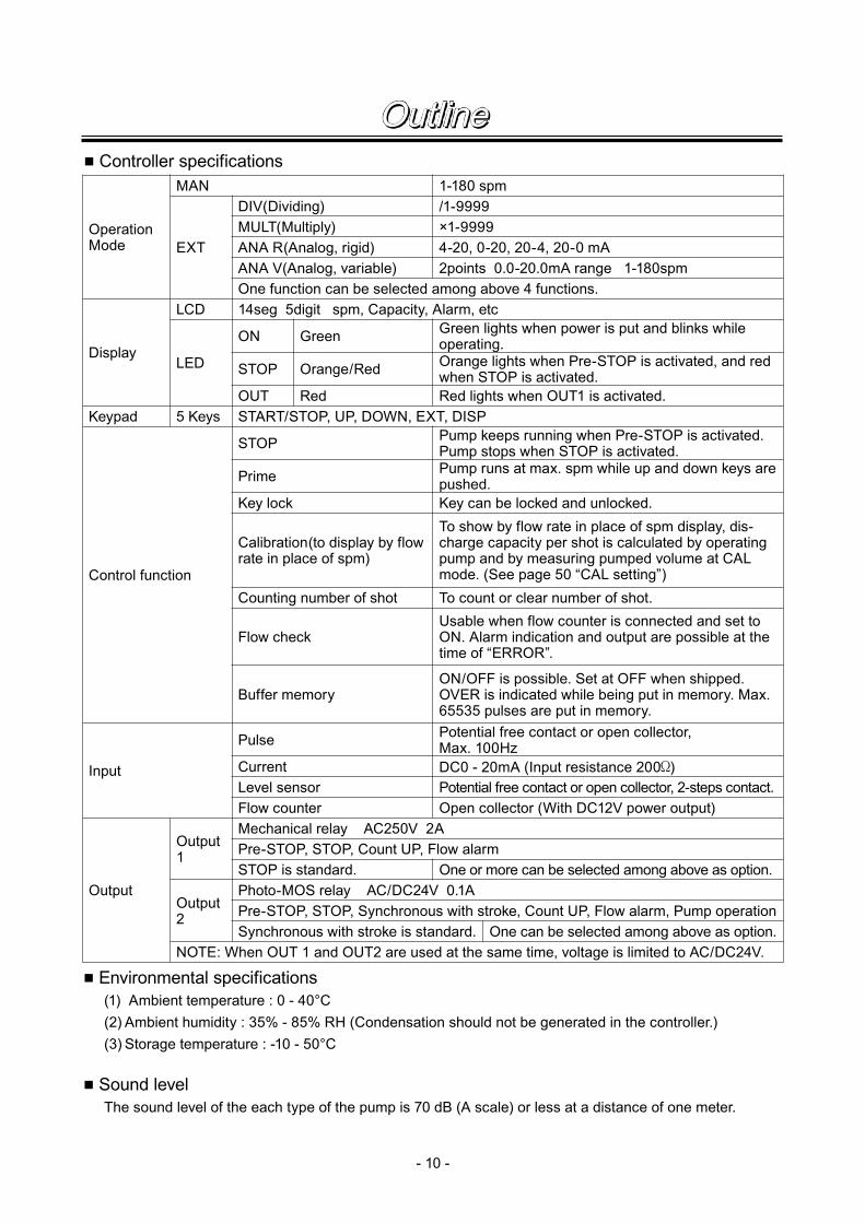
■ Controller specifications
■ Environmental specifications (1) Ambient temperature : 0 - 40°C (2) Ambient humidity : 35% - 85% RH (Condensation should not be generated in the controller.) (3) Storage temperature : -10 - 50°C
■ Sound level The sound level of the each type of the pump is 70 dB (A scale) or less at a distance of one meter.
Operation Mode
MAN
EXT
DIV(Dividing)MULT(Multiply)ANA R(Analog, rigid)ANA V(Analog, variable)One function can be selected among above 4 functions.
Display
LCD
ON Green
STOP
OUT5 Keys START/STOP, UP, DOWN, EXT, DISP
Calibration(to display by flow rate in place of spm)
Input
Output
Output 1
Mechanical relay AC250V 2APre-STOP, STOP, Count UP, Flow alarmSTOP is standard.
Output 2
Photo-MOS relay AC/DC24V 0.1APre-STOP, STOP, Synchronous with stroke, Count UP, Flow alarm, Pump operationSynchronous with stroke is standard.
NOTE: When OUT 1 and OUT2 are used at the same time, voltage is limited to AC/DC24V.
Orange/Red
Red
Control function
Keypad
STOP
Prime
Key lock
Counting number of shot
Flow check
Buffer memory
Pulse
Level sensorFlow counter
Current
14seg 5digit spm, Capacity, Alarm, etc
1-180 spm/1-9999×1-99994-20, 0-20, 20-4, 20-0 mA
LED
Green lights when power is put and blinks while operating.Orange lights when Pre-STOP is activated, and red when STOP is activated.Red lights when OUT1 is activated.
Pump keeps running when Pre-STOP is activated. Pump stops when STOP is activated.Pump runs at max. spm while up and down keys are pushed.Key can be locked and unlocked.To show by flow rate in place of spm display, dis-charge capacity per shot is calculated by operating pump and by measuring pumped volume at CAL mode. (See page 50 “CAL setting”)To count or clear number of shot.Usable when flow counter is connected and set to ON. Alarm indication and output are possible at the time of “ERROR”.
ON/OFF is possible. Set at OFF when shipped. OVER is indicated while being put in memory. Max. 65535 pulses are put in memory.Potential free contact or open collector, Max. 100HzDC0 - 20mA (Input resistance 200 )Potential free contact or open collector, 2-steps contact.Open collector (With DC12V power output)
One or more can be selected among above as option.
One can be selected among above as option.
2points 0.0-20.0mA range 1-180spm
Outline

- 11 -
● EW-F11,F16, F21 G21 Types (VC, VH, PC, PH, TC)
IN
AIROUT
40
125
(254.5)
(67.5)
116 100
6
(194)
(160)
(36)
100
(22.5)
80
106
152015 20
10
(37)
● EW-F31, G31 Types (VC, VH, PC, PH, TC)
40
100
116
6
(182)
(18)
10680
152015 20
100
10
125(67.5)
16
(24.5)
(235.5)
INOUT
Outline5.External Dimensions
- 12 -
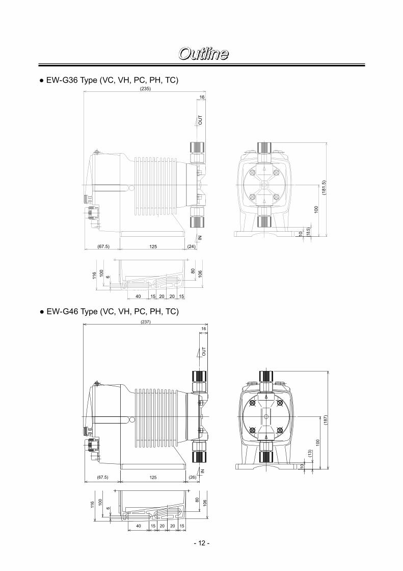
● EW-G36 Type (VC, VH, PC, PH, TC)
● EW-G46 Type (VC, VH, PC, PH, TC)
40
125
(237)
116 100
6
(187)
100
(13)
1515 20 20
10680
(26)
10
16
(67.5)
OUT
IN
40
(235)
125(67.5)
116 100
6
100
(181.5)
15 20 20 15
IN80
106
(24)
10 (18.5
)
16
OUT
Outline
- 13 -
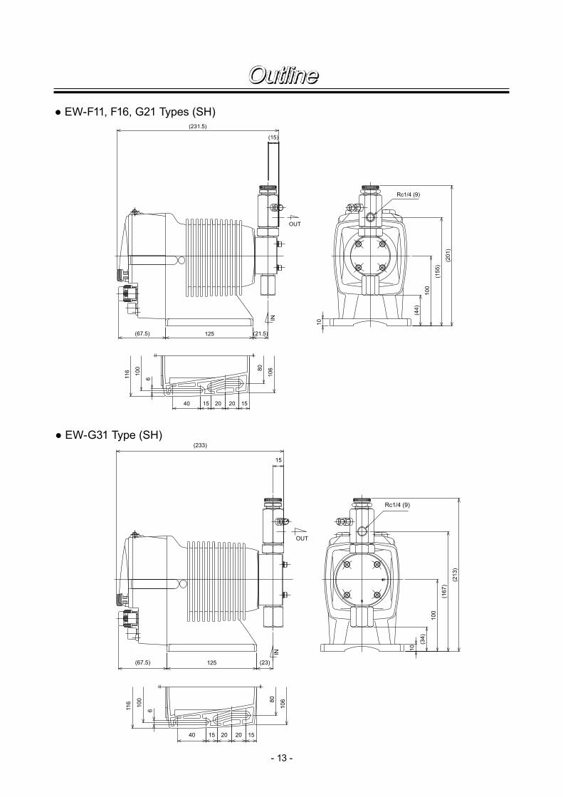
● EW-F11, F16, G21 Types (SH)
IN
OUT
40
125
(231.5)
(67.5)
116 10
0
6
(201
)
(155
)
(44)
100
(21.5)
80
106
152015 20
10
(15)
Rc1/4 (9)
● EW-G31 Type (SH)
40
100
116
6
(167
)
(34)
10680
152015 20
100
10
125(67.5)
15
(23)
(233)
Rc1/4 (9)
(213
)
IN
OUT
Outline

- 14 -
● EW-G46 Type (SH)
40
125
(235)
116 10
0
6
(174
)
100
(27)
1515 20 20
10680
(25)
10
15
(67.5)
(220
)
IN
OUT
Rc1/4 (9)
● EW-G36 Type (SH)
40
(233)
125(67.5)
116 100
6
100
(169
.5)
15 20 20 15
IN80
106
(23)
10
(31.
5)
15
Rc1/4 (9)
(215
.5)
Outline

- 15 -
Operate the pump in accordance with the specifications mentioned in the label.
Label for controlleroperation
Air vent port
Make sure to connect a tubeto return removed air hack to the suction-side tank.
Air vent adjusting screw
Driving unit
Control unit
Nameplate label
Pump unit
Suction port
BaseMake sure to fix the base by fastening screws.
Discharge port
Outline6.Main Parts & Label

- 16 -
1.Before Use ........................................... 17
2.Notes on Operation ............................. 17
3.Installation, Piping, & Wiring ............... 20
Installation

- 17 -
CAUTION● Turn off the power supply
Working without disconnecting the power supply may cause an electrical shock. Before engaging upon any working procedures involving the pump, make sure to turn the power supply switch off and to stop the pump and other related devices.
● Terminate operation When you detect or become aware of a dangerous sign or abnormal condition during operation, terminate the operation immediately and start it from the beginning again.
● Specified power only Do not operate the pump on voltage which is not specified on the nameplate. Failure to do so may result in damage or fire. Only the specified power level is to be applied.
● Keep from heat or flame Do not place any dangerous materials or flammable objects near the pump for the pre-vention of fire or accident.
● Damaged pump Never operate a damaged pump. A damaged pump may cause leakage or electrical shock.
“Strictly observe the following points.”
Operators and maintenance service staff must read the instruction manual thoroughly before using the products. Do not operate the pump system unless all of the contents in the manual are completely understood.
● Dropping the pump or subjecting it to strong impacts may result in faulty performance. Handle the pump with care.
Installation1.Before Use
2.Notes on Operation

- 18 -
● The pump can be operated outdoors, as the pump employs a simple water and dust proof structure.
However, when installing the pump, avoid places exposed to direct sunlight or direct rain with an ambient temperature of above 40ºC, or with a relative humidity of above 85%. Though the pump has a simple waterproof and dustproof structure, a sheltered location is recommended.
● Select an installation site convenient for future maintenance and inspection, and fix the pump on a level floor so that it is free of vibrations.
● Ventilate Ventilate the operating site sufficiently when toxic or odorous liquid is handled.
● Do not wet or dampen If an electric part or wiring gets wet with the liquid spilled over accidentally, a fire or electrical shock may be caused. Install the system in a place free from liquid spillage or leakage.
● Install an earth leakage breaker The operation of a pump without using an earth leakage breaker may cause an electrical shock. Please install an leakage breaker in the system.
Prohibited
Installation

- 19 -
● Limited operating site and storage Do not install or store the pump in the following places:* Places where a flammable gas or material is used
or stored.* Place where the ambient temperature is extremely
high (40ºC or higher) or extremely low (0ºC or lower).
● Cleaning Wiping the pump body or the nameplate with a cloth soaked in a solvent such as benzene, thinner or kerosene may remove or change the color of the coating. Use a dry cloth or a cloth soaked in water or neutral detergent.
Prohibited
Prohibited
Installation

- 20 -
CAUTION
● When you detect or become aware of a dangerous sign or abnormal condition during operation, stop the operation and restart the procedure from the beginning.
■ Installation
[1] Installation Install the pump at a site where the ambient tempera-ture does not exceed 40ºC and the relative humid-ity does not exceed 85%. (There should be no dew condensation inside the control unit.) The site must be selected keeping in mind ease and efficiency for maintenance and inspection work.
[2] Place the pump as close to the suction tank as possible, allowing a flooded suction system (where the pump is located lower than the suction-side tank).
[3] If the pump is used to feed liquid that generates air bubbles easily (sodium hypochlorite, hydrazine solu-tion, etc.), it must be positioned in a cool, dark place away from direct sunlight.
[4] Anchoring pump Select a level floor free of liquid splash, and use M5 screws to firmly anchor the pump so as not to allow any vibration. If the pump is inclined, the discharge volume may be decreased considerably and may lose prime.
[5] Preparation of tube Before the installation of the pump, cut the ends of the tube squarely.
Side view of tube
Caution
Installation3.Installation, Piping, & Wiring

- 21 -
■ Piping<For material codes VC, VH, PC, PH, TC>[1] Piping for pump connection port Use the tube with the correct diameter and make
sure the connecting section does not cause liquid leakage or air suction.
[2] Piping for air elimination process For the safety, connect a tube to the discharge
port of the air vent unit so that the eliminated air can be discharged into the suction tank or like.
[NOTE] The F31, G31, G36 and G46 types are not equipped with an air vent unit.
<For material code SH>1) Connection port is Rc1/4 female threads. Use
proper size of pipe and securely connect pipe so that liquid can not leak or air can not be sucked in.
2) Screw the attached male connector in the bleed port.
3) Connect hose of 4 mm dia. to the male connector. Return the hose end to the tank.
4) Adjust the direction of discharge port to any desired direction.a. Turn the lock nut to left with wrench.b. Adjust the direction of discharge port.c. Holding the air vent body A by hand, turn the
lock nut to right to tighten it.d. Turn the lock nut to left by one fourth turn with
wrench.
Fitting nut
Connecting port
Tube
CAUTION
Since the fitting nut is made of plastic resin, do not fasten it too tightly. This may destroy the part.
Suction portRc 1/4
Lock nut
Discharge portRc 1/4
Male connector
Air vent body A
Installation
- 22 -
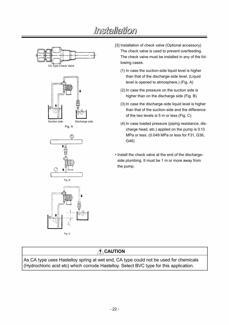
[3] Installation of check valve (Optional accessory) The check valve is used to prevent overfeeding.
The check valve must be installed in any of the fol-lowing cases.
(1) In case the suction-side liquid level is higher than that of the discharge-side level. (Liquid level is opened to atmosphere.) (Fig. A)
(2) In case the pressure on the suction side is higher than on the discharge side (Fig. B)
(3) In case the discharge-side liquid level is higher than that of the suction-side and the difference of the two levels is 5 m or less (Fig. C)
(4) In case loaded pressure (piping resistance, dis-charge head, etc.) applied on the pump is 0.13 MPa or less. (0.049 MPa or less for F31, G36, G46)
• Install the check valve at the end of the discharge-side plumbing. It must be 1 m or more away from the pump.
Fig. C
Fig. B
CAUTION
As CA type uses Hastelloy spring at wet end, CA type could not be used for chemicals (Hydrochloric acid etc) which corrode Hastelloy. Select BVC type for this application.
CA Type Check Valve
Suction side Discharge side
Fig. A
Installation

- 23 -
● Procedure to connect the signal cordUse DIN connector of five poles and four poles.Following connectors made by Binder in Germany are recommended. Ask IWAKI for the detail of Binder connector. 5 poles : 713 series 99-0436-10-05 for input signal 5 poles : 715 series 99-0436-15-05 for flow counter 4 poles : 715 series 99-0430-15-04 for level sensorFollowing connector made by Hirschmann in Germany is recommended. Ask IWAKI for the detail of Hirschmann connector. 4 poles : GDS307 for outputFollowing procedures are based on the connector made by Binder and Hirschmann.If a similar connector is used, the wiring should be made according to the instruction manual of the man-ufacturer of connector.
In case of Binder connector (1) Disassemble the connector and pass the wire through it. Cable out side diameter to be used is ø4-6.
If other diameter cables are used, the connector can not seal properly.
■ Wiring of external signal cord
CAUTION
● Only qualified operators/service staff should be in charge of the related electrical arrangement and control of the power source. Failure to observe this instruction may result in injury to person or damage to assets.
● Never do the wiring when the power is switched on and the pump is operating to avoid electrical shock to the person and pump damage.
● Precautions on wiring*Do not tie up wires for signals with power cord nor with wires for relay output.* Do not share the pump power with that of strong power equipment which generates surge voltage.Otherwise pump controller may be failed.
● Frequent stop and start of pump should be done by using STOP function (ON and OFF of STOP terminal). If you can not use STOP function and are forced to operate pump by turning OFF and ON of power source, ON and OFF of power source should be limited to six times an hour.
(2) Strip the wire ends and insert them to the appropriate positions and tighten them by screws. Max. allowable cross section of the wire is 0.75mm2.
(3) After the screws are tightened, tighten other parts securely. Slightly pull the cord confirm that the cord tightly secured. If the cord is loose, perfect sealing can not be obtained.
Installation

- 24 -
In case of Hirschmann connector(1) Disassemble the connector and pass the wire through it. Insert a minus screw driver into the place shown
by “LIFT” and lift it up. Cable out side diameter to be used is 3.5-6 mm dia. Other diameter cables can not seal properly.
(2) Strip the wire ends and insert them to the appropriate positions and tighten them by screws. Max. allowable cross section of the wire is 0.75mm2.(3) After the screws are tightened, tighten other parts securely. Slightly pull the cord confirm that the cord
tightly secured. If the cord is loose, perfect sealing can not be obtained.
Terminal position
N/A Not Applicable
● Connection of level sensorThe controller corresponds to two stage level sensor. Connect pre-alarm signal to Pre-STOP and alarm signal to STOP. When the pre-alarm signal comes in, orange lamp is lighted but the pump does not stop. When one contact type is used, connect wires to STOP and COM2. · For open collector output level sensor Pay attention to the polarity. Pre-Stop and STOP are plus (+), and COM2 is minus (-). (Max. charged voltage 5V, Current 1.8mA) · For contact output level sensor Use the one designed for electronic circuit and minimum applicable load of 1mA or less.
Connection inside connector 1 : STOP 2 : Pre-STOP 3 : Free 4 : COM2
1
2
3
4 CLOSE
ON
PUMP
Level Sensor(STOP)
OPEN
Pulse
COM1
12V
N/A
ANA
Pre-STOP
STOP
COM2COM3
12V
FC
N/A
N/A
N/A
OUT1
OUT2
● Stop functionStop function means the function to stop the pump by external signal. Connect the wires to STOP and COM2 that is the same way as the level sensor connection.
CAUTION Frequent stop and start of pump should be done by using STOP function (ON and OFF of STOP terminal). If you can not use STOP function and are forced to operate pump by turn-ing OFF and ON of power source, ON and OFF of power source should be limited to six times an hour.
Installation
- 25 -
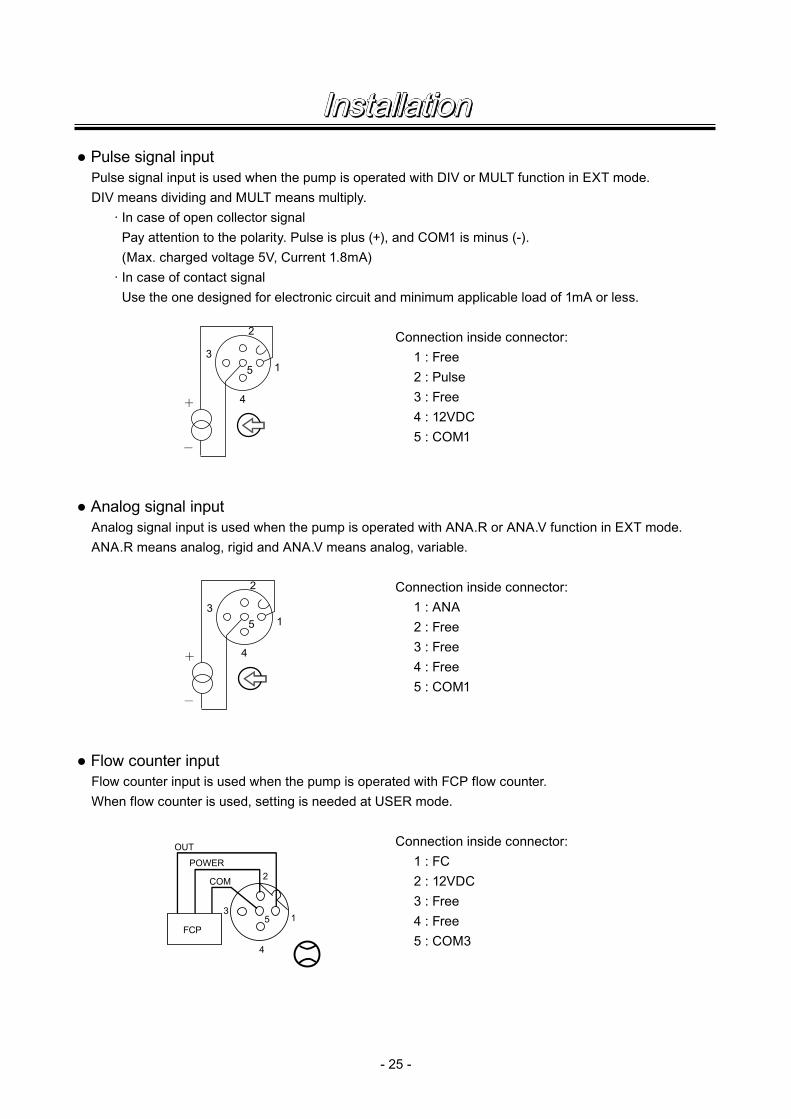
● Pulse signal inputPulse signal input is used when the pump is operated with DIV or MULT function in EXT mode.DIV means dividing and MULT means multiply. · In case of open collector signal Pay attention to the polarity. Pulse is plus (+), and COM1 is minus (-). (Max. charged voltage 5V, Current 1.8mA) · In case of contact signal Use the one designed for electronic circuit and minimum applicable load of 1mA or less.
Connection inside connector: 1 : Free 2 : Pulse 3 : Free 4 : 12VDC 5 : COM1
● Analog signal inputAnalog signal input is used when the pump is operated with ANA.R or ANA.V function in EXT mode.ANA.R means analog, rigid and ANA.V means analog, variable.
Connection inside connector: 1 : ANA 2 : Free 3 : Free 4 : Free 5 : COM1
● Flow counter inputFlow counter input is used when the pump is operated with FCP flow counter. When flow counter is used, setting is needed at USER mode.
Connection inside connector: 1 : FC 2 : 12VDC 3 : Free 4 : Free 5 : COM3
3
2
4
15
COM
POWER
OUT
FCP15
4
3
2
3
2
4
15
Installation

- 26 -
● Output signalOUT1 : Relay output Standard is STOP output: Output is activated when pump stops because of external signal which
comes from level sensor or so.OUT2 : Photo MOS relay output Standard is output synchronous with stroke : Output is activated synchronous with each pump
stroke.NOTE) In case both OUT1 and OUT2 are used simultaneously, both are limited to AC/DC24V or lower.
Connection inside connector: 1 : OUT2 2 : OUT1 3 : OUT1 4 : OUT2
Output function of OUT1 and OUT2 can be changed by setting
OUT2
OUT1
1
2
34
● Surge voltage The electronic circuit of the control unit may be affected by excessively high surge voltage. So, do not operate the pump near high-power electri-cal equipment of 200V or above that generates high surge voltage. Under unavoidable circumstances, take either of the following measures.(1) Use a surge absorbing element (such as a
varistor with surge resistance of 2000A or more) at the pump power supply connection.
(2) Use a noise-cut transformer.
Installation

- 27 -
1.Bleeding .............................................. 28
2.Flow rate Adjustment .......................... 30
3.Operation ............................................ 32
Operation
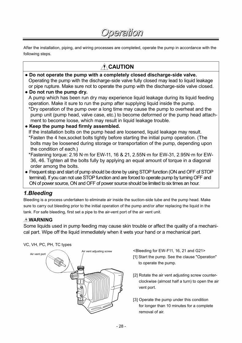
1.BleedingBleeding is a process undertaken to eliminate air inside the suction-side tube and the pump head. Make sure to carry out bleeding prior to the initial operation of the pump and/or after replacing the liquid in the tank. For safe bleeding, first set a pipe to the air-vent port of the air vent unit.
WARNING Some liquids used in pump feeding may cause skin trouble or affect the quality of a mechani-cal part. Wipe off the liquid immediately when it wets your hand or a mechanical part.
VC, VH, PC, PH, TC types<Bleeding for EW-F11, 16, 21 and G21>[1] Start the pump. See the clause "Operation"
to operate the pump.
[2] Rotate the air vent adjusting screw counter-clockwise (almost half a turn) to open the air vent port.
[3] Operate the pump under this condition for longer than 10 minutes for a complete removal of air.
- 28 -
After the installation, piping, and wiring processes are completed, operate the pump in accordance with the following steps.
CAUTION● Do not operate the pump with a completely closed discharge-side valve.
Operating the pump with the discharge-side valve fully closed may lead to liquid leakage or pipe rupture. Make sure not to operate the pump with the discharge-side valve closed.
● Do not run the pump dry. A pump which has been run dry may experience liquid leakage during its liquid feeding operation. Make it sure to run the pump after supplying liquid inside the pump.* Dry operation of the pump over a long time may cause the pump to overheat and the pump unit (pump head, valve case, etc.) to become deformed or the pump head attach-ment to become loose, which may result in liquid leakage trouble.
● Keep the pump head firmly assembled. If the installation bolts on the pump head are loosened, liquid leakage may result.* Fasten the 4 hex,socket bolts tightly before starting the initial pump operation. (The bolts may be loosened during storage or transportation of the pump, depending upon the condition of each.)
* Fastening torque: 2.16 N·m for EW-11, 16 & 21, 2.55N·m for EW-31, 2.95N·m for EW-36, 46. Tighten all the bolts fully by applying an equal amount of torque in a diagonal order among the bolts.
● Frequent stop and start of pump should be done by using STOP function (ON and OFF of STOP terminal). If you can not use STOP function and are forced to operate pump by turning OFF and ON of power source, ON and OFF of power source should be limited to six times an hour.
Air vent adjusting screwAir vent port
Operation

- 29 -
SH type[4] Rotate the air vent adjusting screw clock-
wise to close the air vent valve
[5] Inspect various points for liquid leakage to complete the air elimination process.
<Bleeding for EW-F30, G30, 35, 45 models>[1] Extend the tube connected with the dis-
charge-side fitting nut of the pump to the liquid tank or something like a drain plate. Then, start pump operation.• Remove the check valve if it is installed on
the discharge-side.
[2] Adjust the stroke rate to full speed, and con-tinue operating the pump for about 10 min-utes to eliminate the air completely.
[3] When the air in the pump head is complete-ly eliminated and replaced with liquid, return the discharge-side tube to the regular piping position.
[4] Finally, make sure there is no leakage in any section.
Fitting nut
Check valveshould be removed.
To tank or drain plate
Pump head
Male connector
Air ventadjusting screw
Operation

- 30 -
[1] Procedure for flow rate adjustment Determine the appropriate stroke rate and
stroke length based on pump operation con-ditions and liquid properties. The following method is recommended to determine the set values in consideration of pump per-formance features.
(1) Set the stroke length at 100% and then adjust the stroke rate so that an approxi-mate discharge amount is arranged.
(2) Measure the discharge amount.
(3) If the discharge amount actually measured is lower than required, increase the stroke rate. Then, meas-ure the discharge amount again.
(4) Adjust the stroke length, this time for the purpose of fine adjustment of the discharge amount.
(5) Measure the discharge amount and check that the set amount is precisely discharged.
[2] Adjustment of stroke rate See the clause "Operation" to change
stroke rate. • The stroke rate per minute of the plunger
is controlled by the control unit within a range of 1-180 spm.
0 25 40 50 75 100%Stroke length adjustment
25
50
75
100%
Fixed stroke rate
Flow
rate
180 spm(Stroke rate fixed at 100%)
135 spm(Stroke rate fixed at 75%)
90 spm(Stroke rate fixed at 50%)
0 45 90 135 180spmStroke rate adjustment
25
50
75
100%
Fixed stroke length
Flow
rate
The discharge amount can be adjusted by two methods, namely, stroke speed adjustment and stroke length adjustment, the former being used in most cases. In the event the expected discharge is not exactly obtained by the stroke speed adjustment, the stroke length adjustment is employed as a supplementary.
Operation2.Flow rate Adjustment

- 31 -
[3] Adjustment of stroke length Stroke length can be adjusted by changing
the degree of plunger return.
(1) Start the pump and rotate the stroke length adjusting dial while operating the pump to adjust the discharge amount.
(2) The relation between discharge amount and stroke length is as shown in the graph on the left, where the discharge amount is indicated in percentage.
• The degree of plunger is variable in a range from 0 to 100%. Nevertheless, the usage between 40% and 100% is practical.
Notice(1) For the liquids that easily generate air bubbles (sodium hypochlorite, hydrazine solution etc.),
the flow rate should be adjusted by changing the stroke rate keeping the stroke length at about 100%. If stroke length is short, desired flow rate may not be obtained.
(2) If the back pressure on the discharge side is high, adjust the flow rate by changing stroke rate keeping the stroke length at about 100%.
In the application of neutralization or titration etc., if the reaction is greatly influenced by the volume per shot of pump, adjust the flow rate by stroke rate adjustment keeping the short stroke length to minimize the volume per shot.
0 25 40 50 75 100% Stroke length adjustment
25
50
75
100%
Fixed stroke rate
Flow
rate
CAUTIONDo not rotate the stroke length adjusting dial when the pump stops.
Operation

- 32 -
3.Operation■ OPERATION FUNCTIONManual operation
Set number of stroke with UP and DOWN keys, and start and stop pump with START/STOP key.Stroke rate can be adjusted either pump is running or stops. If flow rate calibration is done at CAL mode, the flow rate can be set in place of stroke rate setting.
Pulse dividing operationPulse dividing operation is done by external pulse signal.Dividing ratio can be set for 9999:1 to 1:1.Max. stroke speed at pulse dividing operation is 180 spm.If pulse signals exceeding the max. number of strokes are put in, the excessive number of strokes can be put in memory up to 65,535.
Pulse multiply operationPump automatically stops after it makes 1 to 9999 counts by one external pulse signal.Stroke speed is that set for manual operation. Number of strokes corresponding to the pulses which are input while multiply operation can be put in memory up to 65,535.
Start/Stop key
Operation
Press Press Press
Run Run
Stop
EXT. Pulse
Pump stroke
1 2 3 4 1 2 3 4 1 2 3 4
Dividing example / 4
EXT. pulse
Pump stroke
1 2 3 4 1 2 3 4 1 2 3 4
Multiplying example 4
Operation
- 33 -
Analog input operation
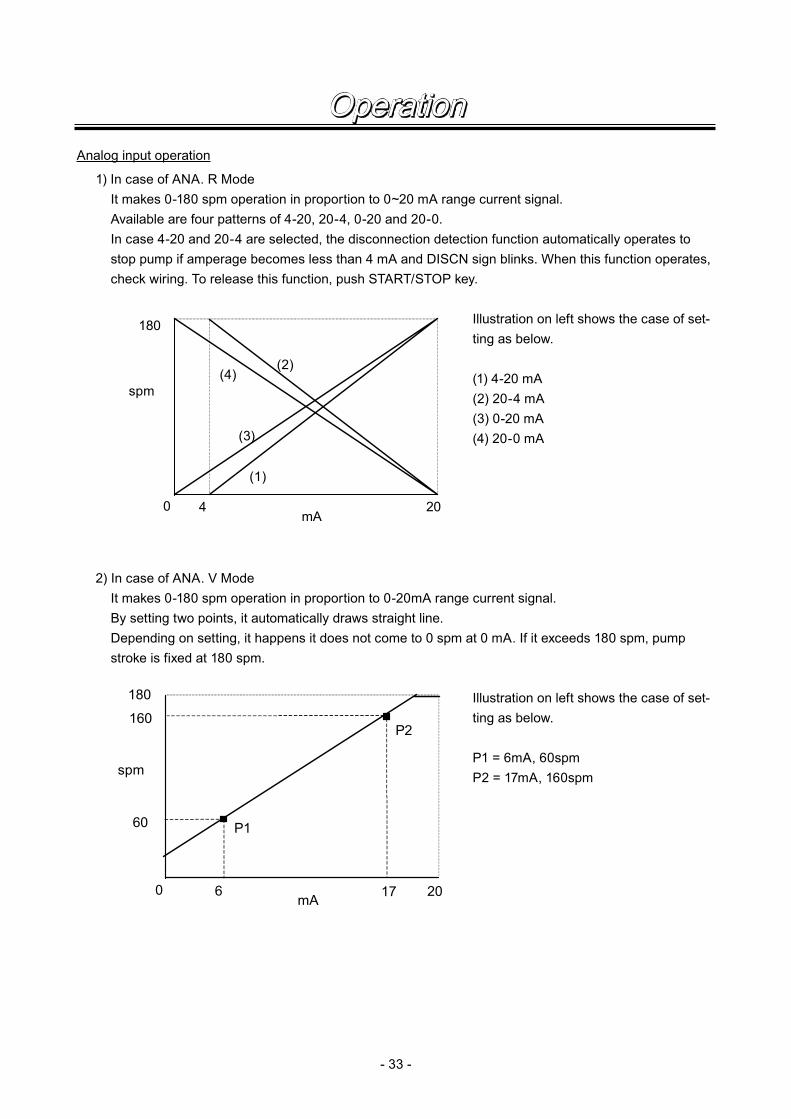
1) In case of ANA. R Mode It makes 0-180 spm operation in proportion to 0~20 mA range current signal. Available are four patterns of 4-20, 20-4, 0-20 and 20-0. In case 4-20 and 20-4 are selected, the disconnection detection function automatically operates to
stop pump if amperage becomes less than 4 mA and DISCN sign blinks. When this function operates, check wiring. To release this function, push START/STOP key.
Illustration on left shows the case of set-ting as below.
(1) 4-20 mA (2) 20-4 mA (3) 0-20 mA (4) 20-0 mA
2) In case of ANA. V Mode It makes 0-180 spm operation in proportion to 0-20mA range current signal. By setting two points, it automatically draws straight line. Depending on setting, it happens it does not come to 0 spm at 0 mA. If it exceeds 180 spm, pump
stroke is fixed at 180 spm.
Illustration on left shows the case of set-ting as below.
P1 = 6mA, 60spm P2 = 17mA, 160spm
0 4 20
180
mA
spm
(1)
(2)
(3)
(4)
0 6 20
180
mA
spm
P1
P2
17
60
160
Operation

- 34 -
MAN
Disp
spm
ANA. V
Disp
L/h
MULT
SET
DIV
Disp
spm
It shows 180 spm at MAN mode.
■ CONTROL PANEL
STOP lampOrange color lights when a Pre-STOP signal comes in from level sensor and red color lights when STOP signal comes in.
START/STOP keyKey to start and stop pump in the manual operation mode.
ON
STOP
MA N DIVMA N DIVMA N DIVMA N DIV MU LTMU LTMU LTMU LT ANA. R VANA. R VANA. R VANA. R V PPPP !!!!
OVER P1 2 LOCK Er r Disp SETOVER P1 2 LOCK Er r Disp SETOVER P1 2 LOCK Er r Disp SETOVER P1 2 LOCK Er r Disp SET
spm spm spm spm mmmm L /h L /h L /h L /h mAmAmAmA
EXT
DISP
OUT
DisplaySet value and operating con-dition are displayed.
Mode indicator Unit indicator
UP keyKey to increase the spm and to change the set value.
DOWN keyKey to decrease the spm and to change the set value.
DISP keyTo interchange spmand flow rate display.
OUT lamp Lamp lights when OUT1 turns on.Status indicator
ON lampLamp lights when the power is on and blinks synchronous with pump stroke during the operation.
EXT keyKey to set pump for exter-nal input operation.
■ BASIC DISPLAY
It shows flow rate during current proportional operation at EXT mode.
Setting number of shots for multiply operation at EXT mode.
Pump stops by STOP input at pulse dividing operation of EXT mode.
Operation

- 35 -
1. means automatic transfer. When the power is switched on for the first time, it comes to WAIT mode. On and after next time, it comes to the status at which the power is switched off.
2. At MAN operation, pump starts operation by pushing START/STOP key at wait mode. Push START/STOP key again to come back to wait mode to stop pump.3. Push EXT key at wait mode to come to EXT mode and to start operation. Push START/STOP key to return wait mode to stop pump.4. Each setting for EXT operation can be done by pushing EXT key at EXT setting mode. After setting is
finished, return to EXT mode by EXT key to execute EXT operation according to changed setting.5. Push DISP key three seconds to change from WAIT mode to CAL mode. CAL mode enables flow rate
indication in place of spm indication by inputting actually measured flow rate.6. Push EXT three seconds to change from WAIT mode to USER mode. At USER mode you can do
detailed setting such as mode selection of EXT operation and setting of output or so.
For details refer to item “Operation”.
■ OVERVIEW OPERATING SCHEME
9
EXT
DISP
WAIT mode
MAN modeEXT mode
USER mode
EXTSet mode
CAL mode
Power on
EXT
EXT
EXT
3sec3sec
EXT
OUT1
OUT2
FL. CHK
ANTI. C
b. MEM
T. C
Operation

- 36 -
■ DISPLAY ELEMENTS
a : MAN Pump is operating at MAN mode.b : DIV Pump is operating at pulse dividing operation at DIV mode EXT.c : MULT Pump is operating at multiplying operation at MULT mode EXT.d : ANA. R V It shows analog input operation. ANA.R is pre-fixed and ANA.V is free two points set-
ting.e : Flow counter is used and it lights and blinks when pulse signal is input.f : spm It shows spm indication.g : L/h It shows liter/hour or Liter indication.h : mA It shows amperage figure at analog setting. i : SET It shows the controller is in setting mode.j : Disp It lights when flow rate and spm indications can be interchanged. k : Err It lights when error happens.l : LOCK It lights when key is locked.m: P12 At ANA.V setting, it lights when two points are indicated. “P1” lights for the first point
and “P2” lights for the second point.n : OVER It lights when stroke is fixed to 180 spm because the stroke exceeds 180 spm by the
calculation for analog input operation and when it is buffered at DIV or MULTI mode when buffer memory is ON.
o : ! It lights as caution purpose when pump is in continuous self-priming operation.p : Operation condition and set value are shown as figures or letters.
MAN DIV MULT ANA.R V P !
OVER P12 LOCK Err Disp SET
spm
a b c df
g
h
ij
e
klmn
o
p L /h
mA
Operation

- 37 -
■ OPERATIONCAUTION
Before turn on pump, check the nameplate on pump if you are putting correct power on pump. Strictly prohibited is other power than shown on pump nameplate is put on pump. Otherwise pump is failed or damaged.
Disp
spm
MAN
MAN
MAN
Disp
spm
Disp
Disp
Disp
Disp
spm
spm
spmANA. V
Turn on power
Manual operation
EXT operation
When the power is turned on initially, the display shows the ver-sion of software and goes to wait mode. On and after the sec-ond time, it comes to the mode at which the power was turned off last time. (If power is off at setting mode, it comes to wait mode first.At wait mode, stroke speed is shown. Lamp lights. (Green)
(2) Push EXT key and it comes to EXT mode and pump starts operation of the EXT function which was decided at USER mode. At the time of shipment from factory, it is set for ANA. V mode which is analog input operation. If other control func-tion is used, change it with mode selection of USER mode. Picture on left shows ANA. V mode.
(1) Move to wait mode Move to wait mode if it is in other mode than wait mode. Go to next step if it is in wait mode.
Flow rate can be set in place of stroke speed.Push DISP key to change display. To set for flow rate display, calibration in CAL mode must be done in advance.See the item “CAL mode”.Push again DISP key to return spm display.
(2) Change of stroke speed Stroke speed is adjusted by UP key and DOWN key. Figure increases by UP key and decreases by DOWN key. If you push key continuously, the figure changes quickly. Stoke speed can be changed while pump runs or stops (wait
mode).
(1) Start & stop (in manual operation) At wait mode, push START/STOP key once to start manual
operation. ON lamp blinks synchronous with pump stroke. Push again START/STOP key and ON lamp lights to come to wait mode.
Operation

- 38 -
At this display you can change to flow rate display by pushing DISP key. If you push DISP key while flow rate is displayed, it changes to spm display. ON lamp blinks simultaneous with pump stroke. Push START/STOP key to come to wait mode.
(3) In DIV mode (dividing function), display shows as left. To change to dividing function, you need to change setting at
USER setting. See item “change of EXT mode” of USER set-ting.
At this display you can change to flow rate display by pushing DISP key. If you push DISP key while flow rate is displayed, it changes to spm display. ON lamp blinks simultaneous with pump stroke. Push START/STOP key to come to wait mode.
(4) MULT mode of count control is displayed as picture on left. Pre-set number of stroke is shown until start signal comes
and the figure is reduced by one every time pump shots one stroke.
To change to count control, setting must be changed in USER setting. See item “change of EXT mode” of USER set-ting.
Remaining volume can be displayed by pushing DISP key.(Remaining volume of batch to be discharged = number of shot × volume per shot)Push DISP key to change to display by number of stroke.ON lamp blinks synchronous with pump stroke.Push START/STOP key to come to wait mode.
(5) Picture on left is ANA. R mode (analog rigid). To change to ANA. R mode, setting must be changed in
USER setting. See item “EXT mode change” of USER set-ting.
Flow rate can be displayed by pushing DISP key.To change to spm display, push DISP key at flow rate display.ON lamp blinks synchronous with pump stroke.To come to wait mode, push START/STOP key.
spm
DIV
DIV
Disp
Disp
Disp
L /h
L /h
L /h
MULT
Disp
MULT
Disp
L
ANA. R
Di sp
spm
ANA. R
Disp
ANA. V
Operation

- 39 -
ANA. V
ANA. V
ANA. V
ANA. V
ANA. V
P1
P1
SET
mA
mA
Disp SET
P1
P 2
P 2
Disp
Disp
SET
SET
SET
L /h
L /h
DIV
DIV mode setting
EXT settingANA. V mode setting
spm
spm
ANA. V
P 2 Disp SET
SET
(1) It comes to ANA. V setting mode by pushing EXT key at ANA. V mode of EXT operation.
This is to explain how to set two points of electric current and stroke speed.
First of all, set current value at P1. Figure increases by push-ing UP key and decreases by DOWN key. If you continue to push it, figure changes quickly.
Push EXT key to move to next setting.(2) Set stroke speed at P1. Figure increases by pushing UP key
and decreases by pushing DOWN key. If you continue to push it, figure changes quickly.
Flow rate can be displayed by pushing DISP key.To change to spm display, push DISP key again.Push EXT key to move to next setting.
(3) Set current at P2. Figure increases by pushing UP key and decreases by pushing DOWN key. If you continue to push it, figure changes quickly.
Push EXT key to move to next setting.
(4) Set stroke speed at P2. Figure increases by pushing UP key and decreases by pushing DOWN key. If you continue to push it, figure changes quickly.
Flow rate can be displayed by pushing DISP key.To change to spm display, push DISP key again.Push EXT key to memorize set value and to return to ANA. V mode operation.
(1) It comes to DIV setting mode if you push EXT key at DIV mode of EXT operation.
This is to explain how to set dividing ratio. Figure increases by pushing UP key and decreases by pushing DOWN key. If key is pushed continuously, figure changes quickly.
Push EXT key to memorize set value and to return DIV func-tion operation.
Operation

- 40 -
ANA.R
mA
MULT
MULT
Disp SET
Disp SET
SET
L
MULT mode setting
ANA. R mode setting
(1) Push EXT key at MULT mode of EXT operation to come to MULT setting mode.
This is to explain how to set number of strokes. Push UP key to increase figure and DOWN key to decrease figure. Figure changes quickly if key is pushed continuously.
Push DISP key to change to flow rate display. Push DISP key again to change to stroke number display.
Push EXT key to memorize set value and to return to MULT control operation.
(1) It comes to ANA. R setting mode by pushing EXT key at ANA. R mode of EXT operation.
This is to explain how to select pattern of analog function. Push UP and DOWN key to select 4-20, 20-4, 0-20 & 20-0.
Push EXT key to memorize set value and to return ANA.R function operation.
Operation

- 41 -
USER settingSetting of each function can be changed at USER mode. Following is a operation flow.
3 seconds
(1)
(2)
(3)
(4)
(5)
(6)
(7)
EXT
FL. CHK
OUT2
OUT1
ANTI. C
b. MEM
T. C
DIV
PST-N
PST-Y
C. UP-N
C. UP-Y
ANA. V
ANA. R
MULT
STP-N
STP-Y
PrST
STOP
P. RUN
F. AL
C. UP
SPM
OFF
C. MODE
b. MODE
A. MODE
ELEC
MECH
ST05
ST20
ST50
FT01
FT02
FT04
10
MEM-N
MEM-Y
EXT DISP
DISP
DISP
DISP DISP
DISP
DISP
DISP
DISP
DISP
DISP
DISP
DISP
DISP
DISP
DISP
10
Operation
- 42 -
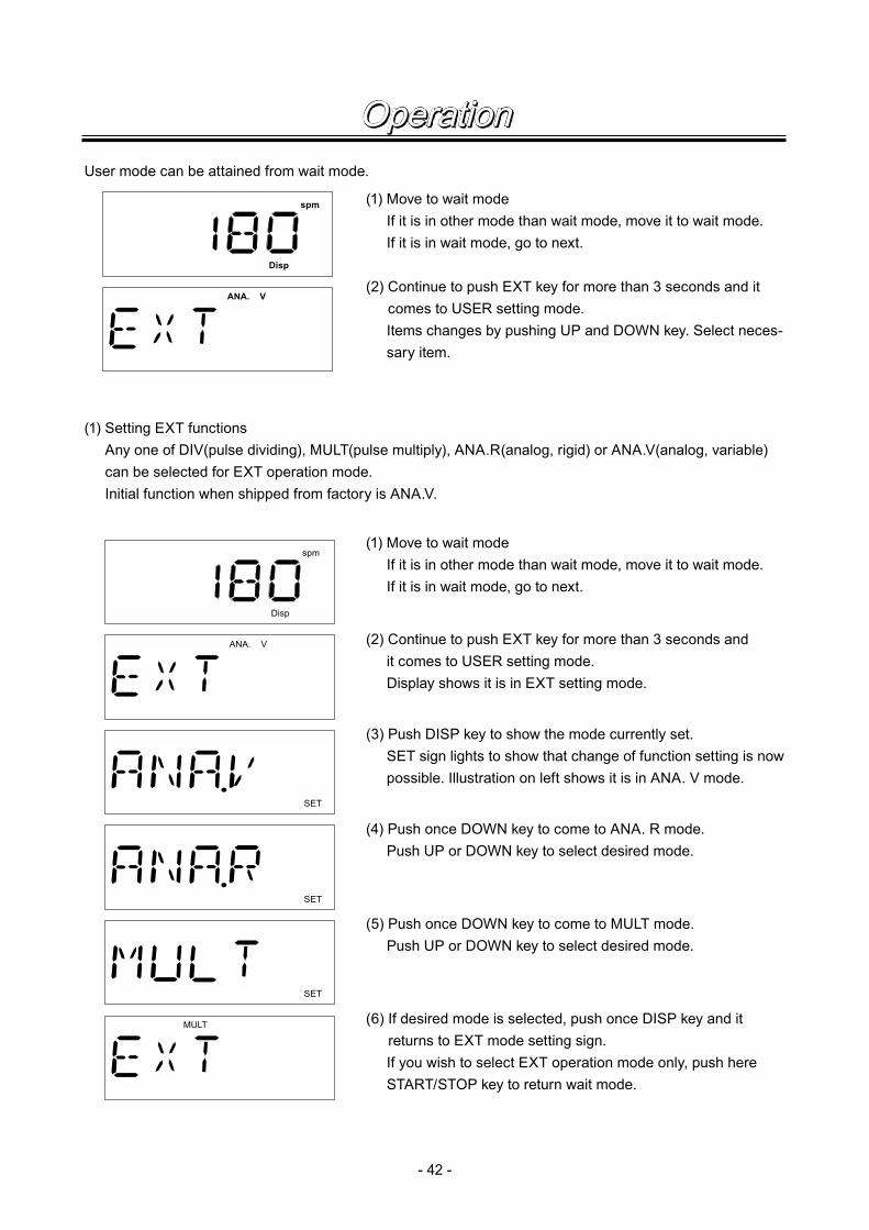
User mode can be attained from wait mode.
Disp
spm
ANA. V
(1) Move to wait mode If it is in other mode than wait mode, move it to wait mode. If it is in wait mode, go to next.
(2) Continue to push EXT key for more than 3 seconds and it comes to USER setting mode.
Items changes by pushing UP and DOWN key. Select neces-sary item.
(1) Setting EXT functions Any one of DIV(pulse dividing), MULT(pulse multiply), ANA.R(analog, rigid) or ANA.V(analog, variable)
can be selected for EXT operation mode. Initial function when shipped from factory is ANA.V.
Disp
spm
ANA. V
SET
SET
SET
MULT
(1) Move to wait mode If it is in other mode than wait mode, move it to wait mode. If it is in wait mode, go to next.
(2) Continue to push EXT key for more than 3 seconds and it comes to USER setting mode. Display shows it is in EXT setting mode.
(3) Push DISP key to show the mode currently set. SET sign lights to show that change of function setting is now
possible. Illustration on left shows it is in ANA. V mode.
(4) Push once DOWN key to come to ANA. R mode. Push UP or DOWN key to select desired mode.
(6) If desired mode is selected, push once DISP key and it returns to EXT mode setting sign.
If you wish to select EXT operation mode only, push here START/STOP key to return wait mode.
(5) Push once DOWN key to come to MULT mode. Push UP or DOWN key to select desired mode.
Operation
- 43 -
Disp
spm
ANA. V
SET
SET
SET
SET
(1) Move to wait mode If it is in other mode than wait mode, move it to wait mode. If it is in wait mode, go to next step.
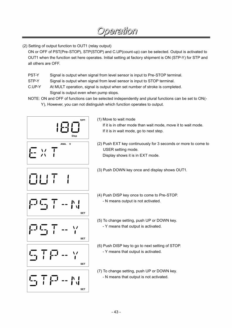
(2) Setting of output function to OUT1 (relay output) ON or OFF of PST(Pre-STOP), STP(STOP) and C.UP(count-up) can be selected. Output is activated to
OUT1 when the function set here operates. Initial setting at factory shipment is ON (STP-Y) for STP and all others are OFF.
PST-Y Signal is output when signal from level sensor is input to Pre-STOP terminal. STP-Y Signal is output when signal from level sensor is input to STOP terminal. C.UP-Y At MULT operation, signal is output when set number of stroke is completed. Signal is output even when pump stops. NOTE: ON and OFF of functions can be selected independently and plural functions can be set to ON(-
Y), However, you can not distinguish which function operates to output.
(2) Push EXT key continuously for 3 seconds or more to come to USER setting mode.
Display shows it is in EXT mode.
(3) Push DOWN key once and display shows OUT1.
(4) Push DISP key once to come to Pre-STOP. - N means output is not activated.
(5) To change setting, push UP or DOWN key. - Y means that output is activated.
(6) Push DISP key to go to next setting of STOP. - Y means that output is activated.
(7) To change setting, push UP or DOWN key. - N means that output is not activated.
Operation

- 44 -
SET
SET
(8) Push DISP key to go to next setting of Count-up. - N means that output is not activated.
(9) To change setting, push UP or DOWN key. - Y means that output is activated.
(10) Push DISP key to come out from setting and return to OUT1 display.
3) Setting of output function to OUT2 (Photo MOS relay) One function can be selected among PrST(Pre-STOP), STOP, spm (synchronous with spm), C.UP
(count-up), F.AL (flow alarm) and P.RUN (pump running). When a function set here operates, output is activated to OUT2. spm is selected when shipped from factory.
PrST : Output is activated when a signal from level sensor is input to Pre-STOP terminal. STOP : Output is activated when a signal from level sensor is input to STOP terminal. spm : Output is activated synchronous with pump stroke. C.UP : At MULT operation, output is activated when number of set stroke is completed. F.AL : By setting flow check, output is activated when pump stops automatically. P.RUN: Output is activated when pump is in operating condition. Output is activated when pump is run-
ning at MAN mode and EXT mode, or when pump is waiting input signal. Output is not activated when STOP function operates or when error happens. Also output is not activated in PRIME condition although pump is running.
(1) Move to wait mode If it is in other mode than wait mode, move it to wait mode. If it is in wait mode, go to next step.
(2) Push EXT key continuously for 3 seconds or more to come to USER setting mode.
Display shows it is in EXT mode.
(3) Push DOWN key once and display shows OUT1.
Disp
spm
ANA. V
Operation
- 45 -
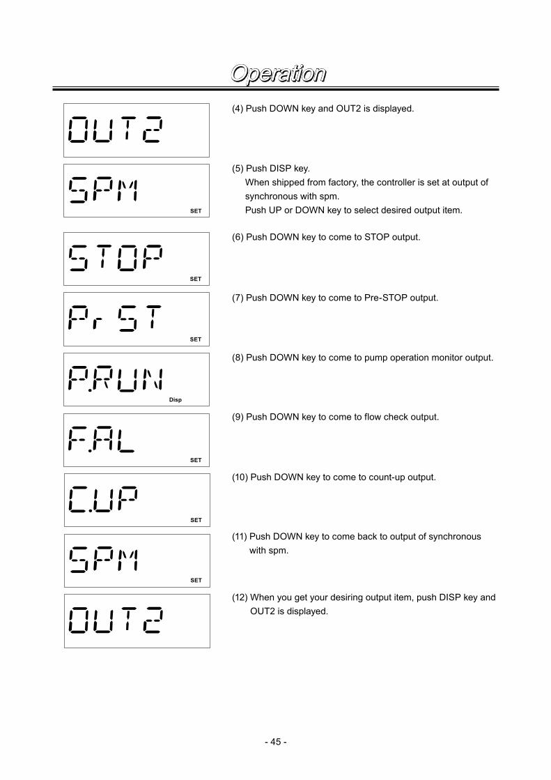
(4) Push DOWN key and OUT2 is displayed.
(5) Push DISP key. When shipped from factory, the controller is set at output of
synchronous with spm. Push UP or DOWN key to select desired output item.
(6) Push DOWN key to come to STOP output.
(7) Push DOWN key to come to Pre-STOP output.
(8) Push DOWN key to come to pump operation monitor output.
(9) Push DOWN key to come to flow check output.
(10) Push DOWN key to come to count-up output.
(11) Push DOWN key to come back to output of synchronous with spm.
(12) When you get your desiring output item, push DISP key and OUT2 is displayed.
SET
SET
SET
Disp
SET
SET
SET
Operation

- 46 -
4) Setting of flow check This function is set to stop pump or to activate alarm signal using optional available flow counter. Any one among A, B or C mode can be selected. Select number of flow check to use this function. This
function is set as OFF and number of flow check is set at ten at the time of shipment.
A MODE operation This is to compare pump shot to signal coming from flow counter and to stop pump and activate output
to OUT1 when continuous dry running pump strokes comes to pre-set number of flow check. In this case, “FLOW” sign blinks and “Err” lights. This situation can be cancelled by START/STOP key. If F.AL is selected at OUT2, output is activated same as OUT1.
Pump
FCP
OUT1
10
B MODE operation This is to compare pump shot to signal coming from flow counter and to activate output to OUT1 when number of dry running pump shots comes to pre-set number of flow check. In this case
pump does not stop but continues to run. If signal is input from flow counter in this situation, output becomes OFF. Pump automatically stops after 360 times shots if signal is not input from flow counter. In this case “FLOW” blinks and “Err” lights. This situation can be cancelled by START/STOP key. If F.AL is selected at OUT2, output is activated same as OUT1.
Pump
FCP
OUT1
+360 10
C MODE operation This is to compare the pump shot to the signal coming from flow counter and to recognize the abnormal-
ity when dry running pump shots comes to the pre-set number of flow check. Output is not activated to OUT1 and pump continues to run but does not stop. Recognition of abnormality is released if a signal is input from flow counter in this situation. Pump automatically stops after 360 times shots if signal is not input from flow counter. In this case “FLOW” blinks and “Err” lights. This situation can be cancelled by START/STOP key. If F.AL is selected at OUT2, output is activated same as OUT1.
Operation

- 47 -
Pump
FCP
OUT1
+360 10
Disp
spm
ANA. V
SET
SET
SET
SET
(1) Move to wait mode If it is in other mode than wait mode, move it to wait mode. If it is in wait mode, go to next step.
(2) Push EXT key continuously 3 seconds to come to USER set-ting mode and EXT is displayed.
(3) Push UP or DOWN key few times to call flow check setting.
(4) Push DISP key to come to flow check mode setting and select with UP or DOWN key.
(6) Push DISP key once to come to setting times of flow check. Set flow check times with UP or DOWN key.
(7) Set with UP key.
(5) Push UP key once to make mode of flow check A.
(8) Push DISP key once to return to flow check display.
Operation

- 48 -
5) Setting of anti-chattering At the time of DIV or MULT operation, anti-chattering function for input pulse can be set. For the pulse of mechanical contact such as relay, set larger figure with MECH and for the high speed
(high frequency) pulse of semi-conductor type contact such as transistor, set smaller figure with ELEC. ST05 for MECH is set when shipped from factory.
Disp
spm
ANA. V
SET
SET
SET
SET
(1) Move to wait mode If it is in other mode than wait mode, move it to wait mode. If it is in wait mode, go to next step.
(2) Push EXT key continuously 3 seconds to come to USER set-ting mode and EXT is displayed.
(3) Push UP or DOWN key few times to call setting of Anti-chat-tering.
(4) Push DISP key. With UP or DOWN key, select MECH. in case mechanical
contact is used and select ELEC. in case semi-conductor contact is used.
6) Setting of buffer memoryIn case pump operation can not follow input pulses for DIV or MULT operation, the pulses can be put in memory. Max. 65,535 pulses can be put in memory. However, this figure can not be kept once power is off or mode is changed. When shipped from factory, it is set at MEM-N for not to be memorized.
(5) Push DOWN key.
(6) Push DISP key.
(7) Push UP key.
(8) Push DISP key to return to Anti-chattering is displayed.
Operation

- 49 -
Disp
spm
ANA. V
SET
SET
(1) Move to wait mode If it is in other mode than wait mode, move it to wait mode. If it is in wait mode, go to next step.
(2) Push EXT key continuously 3 seconds to come to USER set-ting mode and EXT is displayed.
(3) Push UP or DOWN key few times to call buffer memory set-ting.
(4) Push DISP key and set ON or OFF of buffer memory with UP or DOWN key.
(5) Push DOWN key.
(6) Push DISP key and buffer memory setting display is shown.
7) Indication of total number of strokes Total number of pump strokes is shown. It is shown by a thousand unit, so, when you see the figure “1” on
display, it means 1000 to 1999 shots. The figure shown can be deleted by pushing UP and DOWN keys simultaneously.
(1) Move to wait mode If it is in other mode than wait mode, move it to wait mode. If it is in wait mode, go to next step.
Disp
spm
ANA. V (2) Push EXT key continuously 3 seconds to come to USER set-ting mode and EXT is displayed.
Operation
- 50 -
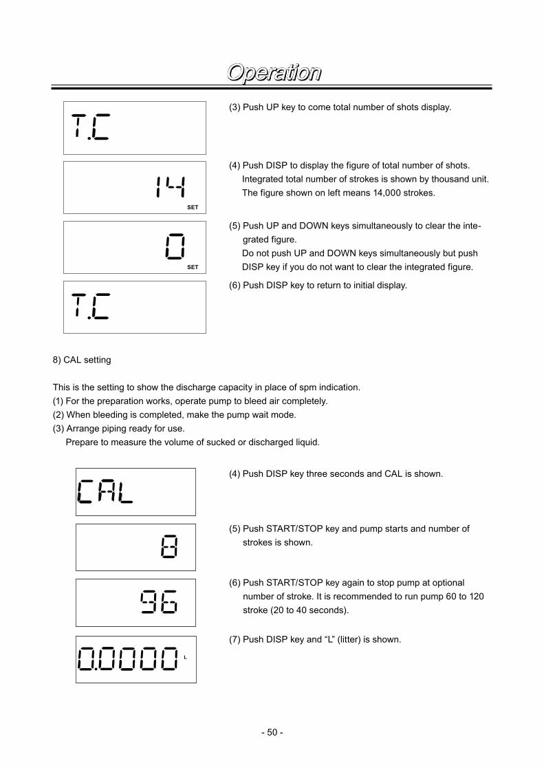
(3) Push UP key to come total number of shots display.
(4) Push DISP to display the figure of total number of shots. Integrated total number of strokes is shown by thousand unit. The figure shown on left means 14,000 strokes.
(5) Push UP and DOWN keys simultaneously to clear the inte-grated figure.
Do not push UP and DOWN keys simultaneously but push DISP key if you do not want to clear the integrated figure.
SET
SET
(6) Push DISP key to return to initial display.
8) CAL setting
This is the setting to show the discharge capacity in place of spm indication.(1) For the preparation works, operate pump to bleed air completely.(2) When bleeding is completed, make the pump wait mode.(3) Arrange piping ready for use. Prepare to measure the volume of sucked or discharged liquid.
L
(4) Push DISP key three seconds and CAL is shown.
(5) Push START/STOP key and pump starts and number of strokes is shown.
(6) Push START/STOP key again to stop pump at optional number of stroke. It is recommended to run pump 60 to 120 stroke (20 to 40 seconds).
(7) Push DISP key and “L” (litter) is shown.
Operation

- 51 -
L
Disp
spm
Disp
L / h
Bleeding & self-priming At wait mode, MAN mode and EXT mode, if UP key and DOWN key are pushed simultaneously, pump
can operate at max. speed taking priority over any function. During both keys are pushed, pump runs at max. speed, and if any one of keys is released, it comes to original mode. Push UP and DOWN keys simultaneously 10 seconds and max. speed operation is fixed. Push any one of UP or DOWN keys to release and to return to original mode.
(8) Put measured liquid volume by UP and DOWN keys.
(9) Push START/STOP key to come to wait mode. Setting is now completed.
(10) Confirm that you can change to flow rate indication by DISP key.
Disp
spm
ANA. V
ANA. V
ANA. V
!
For example, in case that pump is operated at ANA.V mode.
Pump operates at full speed by pushing UP and DOWN keys simultaneously.Display shows PRIME.If any one key is released, it returns to ANA. V mode.
If both UP and DOWN keys are pushed simultaneously ten sec-onds or more, pump continues to runs at full speed even if keys are released. In this case “!” mark lights.Push any one of UP or DOWN key to release and return to ANA. V mode operation.
Operation

- 52 -
Key lockingIf START/STOP key is continuously pushed five seconds, keys can not be operated and LOCK indication lights. This function can be released by continuously pushing START/STOP key five seconds while LOCK is indicated.
MAN
LOCK Disp
spm
ResettingSet figures can be initialized to the status when shipped from factory.Set figures in user mode is returned to initial status. Other setting is kept.For resetting, switch on power while pushing EXT key.
Display shows as left and set figures in user mode are initialized.
Error display and release
Disp
spm
ANA. V
SET
SET
SET
MULT
In case 4-20 or 20-4 is set at ANA.R mode and if input signal becomes 4mA or below due to disconnected wire or so, DISCN sign blinks. In this case check wiring.This can be released by START/STOP key.
FLOW sign blinks when no signal comes from FCP because of dry running or so. This can be released by START/STOP key. After releasing, bleed pump.
NoCAL sign blinks if you try to change to flow rate indication without doing calibration for CAL mode flow rate indication. This case can be released by START/STOP key and do calibration at CAL mode.
Flow rate blinks when stroke length dial is turned after flow rate calibration is done. In this case, do again flow rate calibration at CAL mode.
Operation

- 53 -
1.Causes of Trouble & Troubleshooting .................................. 54
2.Maintenance & Inspection .................. 56
3.Disassembly & Reassembly ............... 57
4.Accessories ........................................ 61
5.Names of Parts & Structure ................ 62
Maintenance
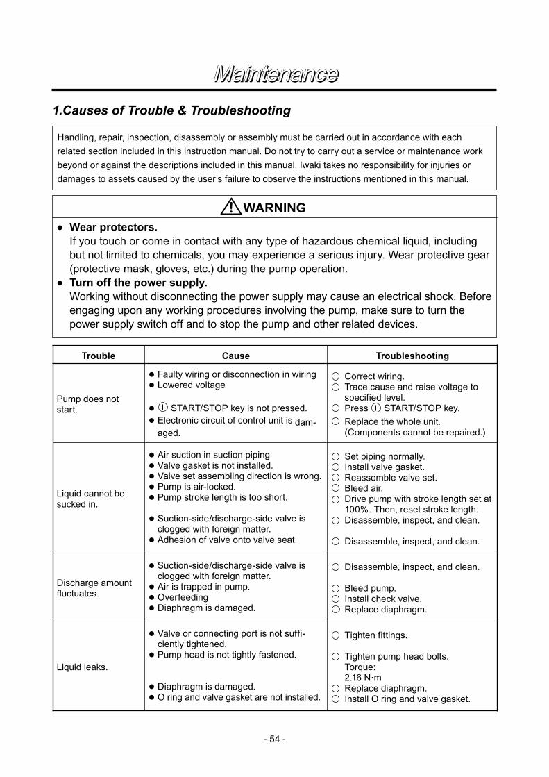
Trouble Cause Troubleshooting
Pump does not start.
● Faulty wiring or disconnection in wiring● Lowered voltage
● START/STOP key is not pressed.● Electronic circuit of control unit is dam-
aged.
Correct wiring.Trace cause and raise voltage to specified level.Press START/STOP key.Replace the whole unit.(Components cannot be repaired.)
Liquid cannot be sucked in.
● Air suction in suction piping● Valve gasket is not installed.● Valve set assembling direction is wrong.● Pump is air-locked.● Pump stroke length is too short.
● Suction-side/discharge-side valve is clogged with foreign matter.
● Adhesion of valve onto valve seat
Set piping normally.Install valve gasket.Reassemble valve set.Bleed air.Drive pump with stroke length set at 100%. Then, reset stroke length.Disassemble, inspect, and clean.
Disassemble, inspect, and clean.
Discharge amount fluctuates.
● Suction-side/discharge-side valve is clogged with foreign matter.
● Air is trapped in pump.● Overfeeding● Diaphragm is damaged.
Disassemble, inspect, and clean.
Bleed pump.Install check valve.Replace diaphragm.
Liquid leaks.
● Valve or connecting port is not suffi-ciently tightened.
● Pump head is not tightly fastened.
● Diaphragm is damaged.● O ring and valve gasket are not installed.
Tighten fittings.
Tighten pump head bolts.Torque: 2.16 N·mReplace diaphragm.Install O ring and valve gasket.
- 54 -
Handling, repair, inspection, disassembly or assembly must be carried out in accordance with each related section included in this instruction manual. Do not try to carry out a service or maintenance work beyond or against the descriptions included in this manual. Iwaki takes no responsibility for injuries or damages to assets caused by the user’s failure to observe the instructions mentioned in this manual.
WARNING● Wear protectors. If you touch or come in contact with any type of hazardous chemical liquid, including
but not limited to chemicals, you may experience a serious injury. Wear protective gear (protective mask, gloves, etc.) during the pump operation.
● Turn off the power supply. Working without disconnecting the power supply may cause an electrical shock. Before
engaging upon any working procedures involving the pump, make sure to turn the power supply switch off and to stop the pump and other related devices.
Maintenance1.Causes of Trouble & Troubleshooting

- 55 -
■ Controller trouble
Trouble Cause Trouble shooting
Keys can not be operated. (1) Key is locked. (1) Release key lock.
Pump does not operate. (1) Set at wait mode(2) Signal is not input at EXT mode.(3) Set at EXT setting mode.
(1) Set operation mode.(2) Check wires connection.(3) Set at EXT operation mode.
Input pulses can not be read. (1) Signal is not input.(2) Anti-chattering is not set cor-
rectly.
(1) Check wiring.(2) Set anti-chattering correctly.
EXT setting is not put in mem-ory.
(1) After setting is finished, START/STOP key wrongly pushed in place of EXT key.
(1) Push EXT key when setting is finished.
Flow rate can not be displayed. (1) Flow rate calibration is not done.
(1) Do flow rate calibration at CAL mode.
Flow rate display blinks. (1) Stroke length dial is rotated after flow rate calibration is done.
(1) Do flow rate calibration again.
Maintenance

- 56 -
2.Maintenance & Inspection■ Daily checkPay attention to the following points during pump operation, and stop pump operation immediately in the event of an abnormality. Take the necessary measures, with reference to the “Causes of Trouble and Troubleshooting” section (p.54). Replace the expendable parts with new ones in accordance with the replacement timing specified below.
No.
1
2
3
Check Point
Does pump discharge liquid normally?
Abnormal noise or vibration?
Is there liquid leakage or air suction at any joint on pump or pip-ing?
Details
• Is liquid normally fed?
• Is suction pressure/discharge pressure at normal level?
• Has liquid undergone quality change, crystallization, or solidification?
• Abnormal noise or vibration may result from abnormal functioning of pump.
• Tighten joint where leakage has occurred.
• Excessive air bubbles in discharged liq-uid mean air suction has been caused in system. Examine the piping and tighten joint which leaks.
How to Check
• By flow meter or visual inspection
• Check nameplate.
• By visual inspection
• By visual and audio inspec-tion
• By visual inspection
► The durability of expendable parts depends on the pressure, temperature, and properties of the liquid han-dled. The value in the above table has been obtained from a continuous test run of the pump using clear water at room temperature. Take the value as a guideline for replacement.
■ Expendable parts
Part Qty. ReplacementTiming Remarks
Valve set
VC, VH, PC, PH, TC SH2
sets
Approx.8,000 hrs.
Diaphragm 1
O ringValve gasket —— *
* Number of parts applicable should be checked with reference to "Names of Parts and Structure of Pump" section.
Maintenance

- 57 -
3.Disassembly & ReassemblyFollow the disassembly and reassembly procedures described below when disassembling or reassembling the pump as necessary for such purposes as replacing expendable parts or overhauling the pump for clean-ing.
<Points to be confirmed before disassembly>• Pay special attention to the presence of residual liquid inside the pump when disassembling the pump.• Wash the wet-end parts in the pump head with water.
■ Replacement of valve set of material codes VC, VH, PC, PH, TC (Refer to exploded view on pages 63)
<Disassembly>[1] Removal of the valve set on the discharge
side (1) Loosen the fitting nut and detach the
tube to the pump. Pay attention to any residual liquid which may flow out of the end of the disconnected tube.
(2) Use a pair of pliers or similar tool to turn the lock nut(6) counterclockwise to remove the air vent unit A(5).
(3) Use a wrench to loosen and remove the air vent unit B(10). Then, take the valve set out of the pump head.
• In the case of EW-F31, G31, G36 & G46 types, use a wrench to loosen and remove the connecting port(3). Then, take the valve set out of the pump head(1).
Fitting nut (4)
Air vent unit B
Lock nut (6)
Pump head (1)
Air vent unit A (5)
(10)
O ring (25)
EW-F31, G31, G36 & G46 types
Connecting port (3)
Maintenance
- 58 -
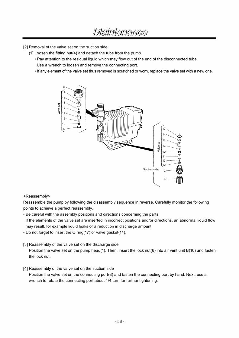
[2] Removal of the valve set on the suction side. (1) Loosen the fitting nut(4) and detach the tube from the pump. • Pay attention to the residual liquid which may flow out of the end of the disconnected tube. Use a wrench to loosen and remove the connecting port. • If any element of the valve set thus removed is scratched or worn, replace the valve set with a new one.
6
14
11
11
13
13
12
12
17 17
14
11
13
13
12
12
3
11
4
Suction side
Valv
e se
t
Valv
e se
t
<Reassembly>Reassemble the pump by following the disassembly sequence in reverse. Carefully monitor the following points to achieve a perfect reassembly.• Be careful with the assembly positions and directions concerning the parts.
If the elements of the valve set are inserted in incorrect positions and/or directions, an abnormal liquid flow may result, for example liquid leaks or a reduction in discharge amount.
• Do not forget to insert the O ring(17) or valve gasket(14).
[3] Reassembly of the valve set on the discharge side Position the valve set on the pump head(1). Then, insert the lock nut(6) into air vent unit B(10) and fasten
the lock nut.
[4] Reassembly of the valve set on the suction side Position the valve set on the connecting port(3) and fasten the connecting port by hand. Next, use a
wrench to rotate the connecting port about 1/4 turn for further tightening.
Maintenance
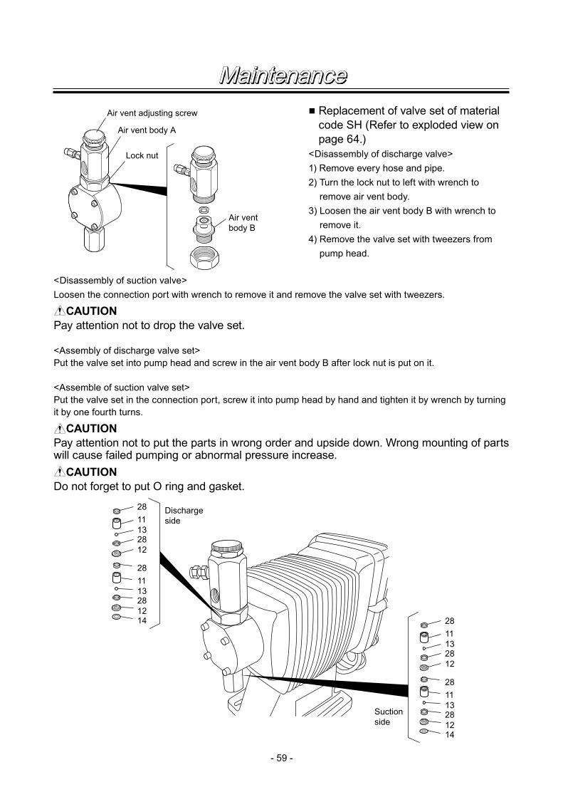
- 59 -
■ Replacement of valve set of material code SH (Refer to exploded view on page 64.)
<Disassembly of discharge valve>1) Remove every hose and pipe.2) Turn the lock nut to left with wrench to
remove air vent body.3) Loosen the air vent body B with wrench to
remove it.4) Remove the valve set with tweezers from
pump head.
<Disassembly of suction valve>Loosen the connection port with wrench to remove it and remove the valve set with tweezers.
CAUTION Pay attention not to drop the valve set.
<Assembly of discharge valve set>Put the valve set into pump head and screw in the air vent body B after lock nut is put on it.
<Assemble of suction valve set>Put the valve set in the connection port, screw it into pump head by hand and tighten it by wrench by turning it by one fourth turns.
CAUTION Pay attention not to put the parts in wrong order and upside down. Wrong mounting of parts will cause failed pumping or abnormal pressure increase.
CAUTION Do not forget to put O ring and gasket.
Air vent adjusting screw
Air vent body A
Lock nut
Air ventbody B
2811132812
2811132812
14
2811132812
2811132812
14
Dischargeside
Suctionside
Maintenance

- 60 -
■ Air vent assemblyUse a wrench to loosen the lock nut(6). Since the air vent unit(A) can be rotated 360 degrees, the tube connection position can be selected freely to satisfy your requirements. The lock nut shall be loosened to make sure that the tube is not posi-tioned over the pump head. Then, fix the position by fastening the lock nut. When fastening the lock nut, hold the air vent unit A(5) with your hand and rotate the lock nut clockwise when viewed from above the pump unit by hand. Then, use a wrench to rotate the lock nut about 1/4 turn for further tightening.
■ Replacement of diaphragm<Disassembly>[1] Loosen the four hex. socket bolts(19) with a
hexagon L-shaped wrench to detach the pump head(1) from the pump body.
[2] Hold the periphery of the diaphragm(7) and rotate the diaphragm counterclockwise to detach it from the plunger pin.• In some cases, some diaphragm spacers are
inserted behind the diaphragm and retainer for positioning. Be careful not to misplace them when replacing the diaphragm.
<Assembly>To reassemble the diaphragm, follow the disas-sembly sequence in reverse, paying attention to the following points.[1] Prior to reassembly, set the pump stroke length
at 100%.• First, start the pump for stroke length setup.
Then, stop the pump and disconnect the power supply.
[2] Insert the retainer(9) and diaphragm spacers(18) into the screwed section of a new diaphragm and screw the diaphragm onto the plunger pin.• Set the concave side of the retainer on the
stepped screw section of the diaphragm so that it will not come off.
Air vent unit (5)
Lock nut (6)
Pump head (1)
Diaphragm
Diaphragm spacer
Retainer
Maintenance

- 61 -
[3] Attach the pump head onto the pump body. Tighten the four hex. socket bolts by applying an equal amount of torque to them.• Tightening torque
EW-11·16·21: 2.16N·mEW-31 : 2.55N·mEW-36·46 : 2.95N·m
4.Accessories■ Specification of check valve(CA, CS), back pressure valve(BVC) (Optional Items)
TypeSet
PressureMPa
Diameterof Fitting
mm
Materialof Liquid
ContactingParts
Applicable Pump
Material Codeof Liquid
ContactingParts of Pump
CA-1V-4 × 6
0.17 ± 0.04ø4 × ø6
CFRPP
EW-F11·16·21EW-G21
PCCA-1E-4 × 6 PH
BVC-1TV-10H0.2 ± 0.02
ø10 × ø12 PVDFEW-G31
TC0.1 ± 0.02 EW-G36·46
CA-2V-9
ø9 × ø12EW-G31
PCCA-2E-9 PHCA-2VL-9 +0.040.05 –0.03
EW-F31EW-G36·46
PCCA-2EL-9 PHCA-1VC-4 × 6
0.17 ± 0.04
ø4 × ø6
PVC
EW-F11·16·21EW-G21
VCCA-1VE-4 × 6 VHCA-1VC-6
ø6 × ø8VC
CA-1VE-6 VHCA-2VC-9
ø9 × ø12EW-G31
VCCA-2VE-9 VHCA-2VCL-9 +0.040.05 –0.03
EW-F31EW-G36·46
VCCA-2VEL-9 VH
BVC-1VV-4H0.2 ± 0.02
ø4 × ø6
PVC
EW-F11·16·21EW-G21
VC
BVC-1VV-9H ø9 × ø12EW-G31
+0.020.10 –0.01EW-F31EW-G36·46
CS-1S 0.2 ± 0.03 Rc 1/4 SUS316 EW-F11·16EW-G21·31 SH
CS-1SL 0.5 ± 0.03 Rc 1/4 SUS316 EW-G36·46 SHBVC-1TV-4H 0.2 ± 0.02 ø4 × ø6 PVDF EW-F11·16, G21 TC
Maintenance
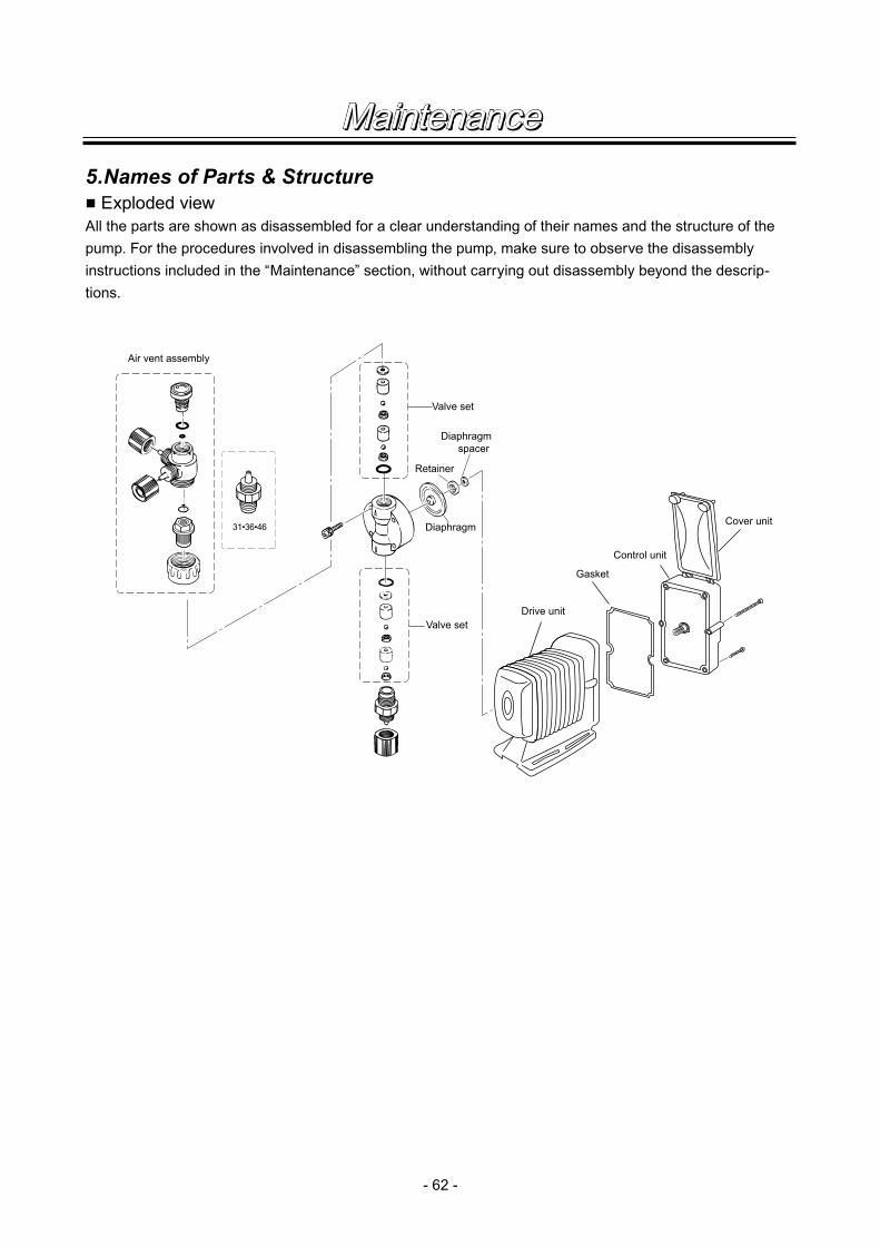
- 62 -
5.Names of Parts & Structure■ Exploded viewAll the parts are shown as disassembled for a clear understanding of their names and the structure of the pump. For the procedures involved in disassembling the pump, make sure to observe the disassembly instructions included in the “Maintenance” section, without carrying out disassembly beyond the descrip-tions.
Valve set
Valve set
Diaphragm spacer
Diaphragm
Retainer
Drive unit
Gasket
Cover unit
Control unit
31•36•46
Air vent assembly
Maintenance
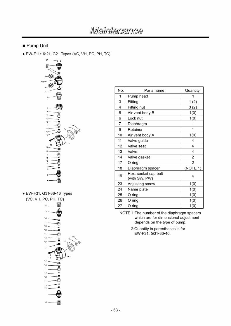
- 63 -
■ Pump Unit
● EW-F11•16•21, G21 Types (VC, VH, PC, PH, TC)
● EW-F31, G31•36•46 Types (VC, VH, PC, PH, TC)
No. QuantityParts name1 1
1 (2)3 (2)1(0)1(0)
11
1(0)44422
(NOTE 1)
4
1(0)1(0)1(0)
345679
10111213141718
19
232425
Pump headFittingFitting nutAir vent body BLock nutDiaphragmRetainerAir vent body AValve guideValve seatValveValve gasketO ringDiaphragm spacerHex. socket cap bolt(with SW, PW)Adjusting screwName plateO ring
NOTE 1:The number of the diaphragm spacers which are for dimensional adjustment depends on the type of pump.
2:Quantity in parentheses is for EW-F31, G31•36•46.
1(0)1(0)
2627
O ringO ring4
3
14
1113
12
1113
12
1411
13
12
11
12
1
4
13
17
1719
79
18
Maintenance
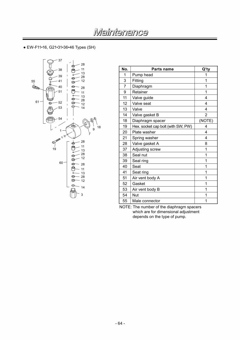
- 64 -
● EW-F11•16, G21•31•36•46 Types (SH)
61
60
55
37
2811132812
2811132812
2811132812
2811132812
14
3
14
189
71
19
38
3941
4051
52
54
53
NOTE: The number of the diaphragm spacers which are for dimensional adjustment depends on the type of pump.
No. Parts name Q’ty1 Pump head 13 Fitting 17 Diaphragm 19 Retainer 111 Valve guide 412 Valve seat 413 Valve 414 Valve gasket B 218 Diaphragm spacer (NOTE)19 Hex. socket cap bolt (with SW, PW) 420 Plate washer 421 Spring washer 428 Valve gasket A 837 Adjusting screw 138 Seal nut 139 Seal ring 140 Seat 141 Seat ring 151 Air vent body A 152 Gasket 153
55 Male connector 1
Air vent body B 154 Nut 1
Maintenance

Read this manual before use of product
IWAKIElectromagnetic Metering PumpEW-Y SeriesInstruction Manual
T492-2 '07/10
( )Country codes
IWAKI CO.,LTD. 6-6 Kanda-Sudacho 2-chome Chiyoda-ku Tokyo 101-8558 JapanTEL:(81)3 3254 2935 FAX:3 3252 8892(http://www.iwakipumps.jp)
U.S.A. : IWAKI America Inc.Australia : IWAKI Pumps Australia Pty. Ltd.Singapore : IWAKI Singapore Pte. Ltd.Indonesia : IWAKI Singapore (Indonesia Branch)Malaysia : IWAKIm Sdn. Bhd.Taiwan : IWAKI Pumps Taiwan Co., Ltd.Thailand : IWAKI (Thailand) Co.,Ltd.Hong Kong : IWAKI Pumps Co., Ltd.China : GFTZ IWAKI Engineering & Trading Co., Ltd.China : IWAKI Pumps Co., Ltd. (Beijing office)China : IWAKI Pumps (Shanghai) Co., Ltd.Philippines : IWAKI Chemical Pumps Philippines, Inc.Korea : IWAKI Korea Co.,Ltd.Vietnam : IWAKI Pumps Vietnam Joint Venture Co.,Ltd.
TEL : (1)508 429 1440 FAX : 508 429 1386TEL : (61)2 9899 2411 FAX : 2 9899 2421TEL : (65)763 2744 FAX : 763 2372TEL : (62)21 690 6607 FAX : 21 690 6612TEL : (60)3 7803 8807 FAX : 3 7803 4800TEL : (886)2 8227 6900 FAX : 2 8227 6818TEL : (66)2 320 1303 FAX : 2 322 2477TEL : (852)2 607 1168 FAX : 2 607 1000TEL : (86)20 8435 0603 FAX : 20 8435 9181TEL : (86)10 6442 7713 FAX : 10 6442 7712TEL : (86)21 6272 7502 FAX : 21 6272 6929TEL : (63)2 888 0245 FAX : 2 843 3096TEL : (82)2 3474 0523 FAX : 2 3474 0221TEL : (84)613 933456 FAX : 613 933399
Germany : IWAKI EUROPE GmbHItaly : IWAKI Italia S.R.L.Denmark : IWAKI Pumper A/SSweden : IWAKI Sverige ABFinland : IWAKI Suomi OyNorway : IWAKI Norge ASFrance : IWAKI France S.A.U.K. : IWAKI PUMPS (UK) LTD.Switzerland : IWAKI (Schweiz) AGAustria : IWAKI (Austria) GmbHHolland : IWAKI Holland B.V.Spain : IWAKI Iberica Pumps, S.A.Belgium : IWAKI Belgium n.v.
TEL : (49)2154 9254 0 FAX : 2154 1028TEL : (39)02 990 3931 FAX : 02 990 42888TEL : (45)48 24 2345 FAX : 48 24 2346TEL : (46)8 511 72900 FAX : 8 511 72922TEL : (358)9 2742714 FAX : 9 2742715TEL : (47)66 81 16 60 FAX : 66 81 16 61TEL : (33)1 69 63 33 70 FAX : 1 64 49 92 73TEL : (44)1743 231363 FAX : 1743 366507TEL : (41)32 3235024 FAX : 32 3226084TEL : (43)2236 33469 FAX : 2236 33469TEL : (31)297 241121 FAX : 297 273902TEL : (34)943 630030 FAX : 943 628799TEL : (32)1430 7007 FAX : 1430 7008