ivw - schriftenreihe band 74¡r+2007+-+stitching... · oder kleben (binder-technik). ziel der...
TRANSCRIPT

IVW - Schriftenreihe Band 74 Institut für Verbundwerkstoffe GmbH - Kaiserslautern _________________________________
Péter Molnár Stitching Technique Supported Preform Technology for Manufactoring Fiber Reinforced Polymer Composites

Bibliografische Information Der Deutschen Bibliothek Die Deutsche Bibliothek verzeichnet diese Publikation in der Deutschen Nationalbibliografie; detaillierte bibliografische Daten sind im Internet über <http://dnb.ddb.de> abrufbar. Bibliographic information published by Die Deutsche Bibliothek Die Deutsche Bibliothek lists this publication in the Deutsche Nationalbibliografie; detailed bibliographic data is available in the Internet at <http://dnb.ddb.de>.
Herausgeber: Institut für Verbundwerkstoffe GmbH Prof. Dr.-Ing. Alois K. Schlarb Erwin-Schrödinger-Straße TU Kaiserslautern, Gebäude 58 67663 Kaiserslautern http://www.ivw.uni-kl.de Verlag: Institut für Verbundwerkstoffe GmbH Druck: Technische Universität Kaiserslautern ZBT – Abteilung Foto-Repro-Druck D 386 © Institut für Verbundwerkstoffe GmbH, Kaiserslautern 2007 Alle Rechte vorbehalten, auch das des auszugsweisen Nachdrucks, der auszugsweisen oder vollständigen Wiedergabe (Photographie, Mikroskopie), der Speicherung in Datenverarbeitungsanlagen und das der Übersetzung. Als Manuskript gedruckt. Printed in Germany. ISSN 1615-021X ISBN 978-3-934930-70-0 ISBN 3-934930-70-4

Stitching Technique Supported Preform Technology for Manufacturing Fiber Reinforced Polymer Composites
Beim Fachbereich für Maschinenbau und Verfahrenstechnik
der Universität Kaiserslautern
genehmigte Dissertation
zur Erlangung des akademischen Grades
Doktor-Ingenieur (Dr.-Ing.)
vorgelegt von
MSc. Péter Molnár
aus Szeged, UNGARN
Tag der mündlichen Prüfung: 12.07.2007
Prüfungsvorsitzender: Prof. Dr.-Ing. Rainer Renz
1. Berichterstatter: Prof. Dr.-Ing. Peter Mitschang
2. Berichterstatter: Prof. Dr.-Ing. Tibor Czigány
D 386


Vorwort I
___________________________________________________________________
Vorwort
Die vorliegende Dissertation entstand während meiner Tätigkeit als
wissenschaftlicher Mitarbeiter bei der Institut für Verbundwerkstoffe GmbH in der Zeit
von 2002 bis 2007 in Kaiserslautern.
Meinem Doktorvater Herrn Prof. Dr.-Ing. Peter Mitschang danke ich für das mir
entgegenbrachte Vertrauen, die produktiven fachlichen Gespräche und für die
umfassende Unterstützung während meiner Zeit am IVW.
Ebenso danke ich Herrn Prof. Dr.-Ing. Rainer Renz für die Übernahme des
Prüfungsvorsitzes und Herrn Prof. Dr.-Ing. Tibor Czigány für die Übernahme des
Korreferats, für die Unterstützung während meines Studiums an der Technischen
und Wirtschaftswissenschaftlichen Universität Budapest und für seine konstruktive
Kritik an dieser Arbeit.
Den Mitarbeitern der IVW GmbH, insbesondere den Kollegen der Abteilung
Verarbeitungstechnik, danke ich herzlich für die gute Zusammenarbeit, die viele Hilfe
und Unterstützung während der wertvollen fünf Jahre.
Besonderes möchte ich mich auch bei A. Hodács, A. Ogale, B. Fodor, B. Zsigmond,
C. Reizer, D. Felhös, F. Weyrauch, H. Stadtfeld J. Langmack, J. Schlimbach, K-H.
Hammer, V. Disandt und V. Nagy für die schöne Zeit und kreative Zusammenarbeit
am Institut und an der Dissertation bedanken.
Für die vielen interessanten Forschungsarbeiten bedanke ich mich bei der BMBF,
der German Honda Initiation Grant und der Europäischen Kommission für die
gewährte finanzielle Unterstützung der Projekte, innerhalb derer Teile diese Arbeit
entstanden.
Ganz besonderer Dank gilt meiner Familie für die kontinuierliche Unterstützung
sowie den Rückhalt während meiner Ausbildung und meines bisherigen beruflichen
Werdegangs.
Kaiserslautern, August 2007 Péter Molnár

II
___________________________________________________________________
Für meine Familie
Kurzfassung III
___________________________________________________________________
Kurzfassung
Im Zuge der steigenden Anzahl von Einsatzmöglichkeiten der
Faserverbundwerkstoffe in den verschiedensten Industriebereichen spielt die
Entwicklung bzw. Weiterentwicklung neuer und effektiverer Verarbeitungstechniken
eine bedeutende Rolle.
Dabei findet derzeit das Harzinjektionsverfahren (LCM) ausschließlich für kleinere bis
mittlere Stückzahlen seinen Einsatz. Aufgrund der sehr großen Stückzahlen im
Automobilbereich, ist dieses Verfahren hier zurzeit weniger interessant. Daher
werden große Anstrengungen unternommen, das Harzinjektionsverfahren besonders
für solche Bauteile attraktiver zu machen, die gegenwärtig mit Hilfe des Prepreg-
Verfahrens hergestellt werden. Dabei spielt die Reduktion der hier vergleichsweise
hohen Zykluszeit eine tragende Rolle. Die Dauer eines Zyklus wird hierbei
hauptsächlich durch die Vorbereitung und Herstellung der Verstärkungsstruktur
(Preform) sowie durch die Bestückung des Werkzeuges bestimmt. Diese so
genannte Preform-Technik weist daher ein sehr großes Entwicklungspotential auf,
mit dem Ziel, solche Verstärkungsstrukturen herzustellen, die nach der Injektion
keine Nacharbeit erfordern. Solche Strukturen werden auch als „net shape, ready-to-
impregnate“- Preform bezeichnet. Die hierfür notwendigen Techniken stammen
vornehmend aus der Textilindustrie, wie z.B. die direkte Preformtechnik, das Nähen
oder Kleben (Binder-Technik).
Ziel der vorliegenden Dissertation ist es, die Möglichkeiten der Nähtechnik bezogen
auf die Herstellung der Preforms zu untersuchen. Hierfür werden die verschiedenen
Naht- und Verbindungsarten hinsichtlich ihres Einsatzes in der Preformtechnik, wie
die Fixier- und Positionier-, die Füge- oder Verbindungsnaht und die Montagenaht,
untersucht.
Im Rahmen dieser Arbeit wurde zunächst innerhalb einer Studie zur „net shape“-
Preformtechnik eine Versteifungsstruktur entwickelt und hergestellt. Diese Struktur
soll dabei der Veranschaulichung der Möglichkeiten und Einsatzbereiche der
Nähtechnik bei der Preformtechnologie dienen. Zudem kann so ein mehrstufiger
Preformherstellungsprozess demonstriert werden. Ferner zeigt diese Studie, dass
ein hochgradiger, automatisierter Prozess, welcher zudem eine durchgängige
Qualitätskontrolle ermöglicht, realisiert werden konnte.

IV
___________________________________________________________________
Als ein weiterer Schritt wurde ein Prozess zur Herstellung eine dreidimensionalen
Preform, der die Anwendung verschiedener thermoplastischer,
niedrigtemperaturschmelzender Nähgarne zulässt, ausgearbeitet. Hierbei wurden die
Vorteile der Näh- und der Binder-Technologie miteinander verbunden. Außerdem
konnte durch die bereits formstabile und imprägnierungsfertige Preformstruktur, die
Bestückung des Werkzeuges wesentlich vereinfacht werden. Um die mechanischen
Eigenschaften der Preforms bestimmen zu können, wurden quantitative
Messmethoden erarbeitet. Hierdurch konnten anschließend die Einflüsse der
Orientierung sowie der Stichdichte ermittelt werden. Zudem wurden die folgenden
drei grundlegenden Eigenschaften untersucht: die spezifische Biegesteifigkeit, der so
genannte Rückspringwinkel sowie die Rückstellkraft nach dem Thermoformen
hinsichtlich der verschiedenen Nähtypen.
Um dies zu ergänzen, wurden weiterführende Untersuchungen zu den
Materialeigenschaften der Nähfäden, die bei der dreidimensionalen Preformtechnik
eingesetzt werden können, durchgeführt. Dabei ist neben der niedrigen
Schmelztemperatur die vollständige Auflösbarkeit der Nähgarne in den ungesättigten
Polyester- und Epoxidharzen besonders wichtig. Auf Grund dieser vollständigen
Auflösung der Fäden in der Matrix können die Stichlöcher wieder vollkommen
verschlossen werden. Dadurch kann eine Reduktion des Einflusses solcher
Stichlöcher auf die mechanischen Eigenschaften des Faserverbundwerkstoffes
erreicht werden. Mit Hilfe dieser Untersuchungen wurden schließlich zwei polymere
Nähgarne als vielversprechend beurteilt. Diese weisen eine Schmelztemperatur von
weniger als 100 °C sowie eine gute Lösbarkeit, besonders im Harzsystem RTM 6,
auf.
In der Preformtechnik werden die Nähte nicht nur als Positionier- oder Montagenaht
eingesetzt, sondern können in einer Struktur als auch als Verstärkungselement, eine
so genannte Verstärkungsnaht, verwendet werden. Der Zweck einer solchen Naht ist
die interlaminare Verstärkung von monolitischen oder Sandwichstrukturen. Zudem
besteht die Möglichkeit, diese zur Fixierung von metallischen Funktionselementen
(Inserts) in den Faserverbundwerkstoff zu benutzen. Hinsichtlich diese Möglichkeiten
wurden im Rahmen dieser Arbeit erfolgreich Untersuchung durchgeführt. Dabei
wiesen die eingenähten Krafteinleitungselemente in durchgeführten statischen
Zugversuchen eine annähernd 200 % höhere maximale Zugkraft verglichen mit
entsprechenden Elementen (BigHead®), die nicht durch eine Naht fixiert wurden.

Kurzfassung V
___________________________________________________________________
Weitere Untersuchungen zeigten auch, dass eine doppelte Naht nicht eine
proportionale Verdoppelung der maximal erreichbaren Zugkraft bewirkt. Der Grund
hierfür liegt an einer partiellen Zerstörung des vorhandenen Nähgarns der ersten
Naht begründet durch den doppelten Einstich in die bereits bestehenden Löcher
beim mehrmaligen Durchlaufen der Nadel. Der größte Verstärkungseffekt konnte
schließlich bei der interlaminaren Einbettung und der Vernähung des Insert erreicht
werden. In diesem Fall kann eine Delamination, wie sie bei lediglich interlaminar
eingebetteten Inserts auftritt, verhindert werden.
Zusätzlich wurden statische Scherversuche durchgeführt, um auch in diesem
Belastungsfall die Versagensart zu untersuchen. Dabei stellte sich heraus, dass nicht
die Nähte sondern der Insert versagte. Auf Grund des Materialbruchs des Inserts,
sowohl in Zug- als auch in Scherversuchen, wurde in einem weiteren Schritt ein
optimiertes Insert entwickelt. Bei diesem wurde der Sockel in soweit modifiziert, dass
die maximale Versagenslast des Nähgarns ermittelt werden konnte. Dabei stellte
sich heraus, dass Glas-, Kohlenstoff- und Aramidfasern sich nur bedingt als
Verstärkungsgarn zur Fixierung von Inserts eignen. Im Gegensatz dazu sind die
Polyestergarne als ausreichende Verstärkung gut geeignet. Weitere Vorteile des
Polyestergarns sind die niedrigeren Kosten sowie die gute Vernähbarkeit.
Anschließend wurde eine solche Verbindung des Inserts mit einem
Faserverbundwerkstoff mit Hilfe der Finite-Elemente-Methode (FEM) simuliert. Dabei
zeigte sich eine gute Übereinstimmung der simulierten Ergebnisse mit denen aus
dem statischen Zugversuch mit dem weiterentwickelten Insert.
Auf Grund der elektrischen Leitfähigkeit von Kohlenstofffasern, können Fäden aus
diesem Material auch als Sensoren zur Überwachung einer Struktur oder Verbindung
eingesetzt werden. Hierfür wurden ebenfalls Untersuchungen durchgeführt. Dabei
konnte mit Hilfe der Änderung des elektrischen Widerstandes auf Schädigungen der
Fasern geschlossen werden. Somit können nicht nur das Bestehen einer
Schädigung, sondern auch der annähernde Ort ermittelt werden. Die
Untersuchungen zeigten somit, dass die Kohlenstofffasern nicht lediglich als
Verstärkung sondern auch als Überwachungssensor bei einem eingebetteten Insert
dienen können.
Im Rahmen aller Untersuchungen konnte das große und vielversprechende Potential
der Nähtechnik bei der Herstellung von Preform-Bauteilen aufgezeigt sowie ein
Einblick in einige von vielen Anwendungsmöglichkeiten gegeben werden.

VI
___________________________________________________________________

Content VII
___________________________________________________________________
Content
VORWORT.................................................................................................................. I
KURZFASSUNG ....................................................................................................... III
CONTENT ................................................................................................................ VII
SYMBOLS ................................................................................................................. IX
ABBREVIATIONS..................................................................................................... XII
INTRODUCTION ........................................................................................................ 1
OBJECTIVE OF THE DISSERTATION ...................................................................... 4
1 PREFORM TECHNIQUE FOR LIQUID COMPOSITE MOLDING
TECHNOLOGIES ....................................................................................................... 6
1.1 THREE DIMENSIONAL PREFORMING BY MEANS OF STITCHING TECHNOLOGIES ....... 7
1.2 PHILOSOPHY OF THE STITCHING SUPPORTED PREFORM-LCM PROCESS CHAIN... 18
2 APPLICATION OF SOLUBLE BONDING YARNS TO ASSEMBLE 3D
PREFORM STRUCTURES ...................................................................................... 20
2.1 APPLICATION OF BONDING YARNS IN 3D PREFORM MANUFACTURING ................. 21
2.2 TESTING OF THE PERFORM MECHANICAL PROPERTIES ...................................... 22
2.3 EXPERIMENTAL PROCEDURE.......................................................................... 25
2.3.1 Bending Stiffness.................................................................................... 25
2.3.2 Spring back angle ................................................................................... 27
2.3.3 Restoring force ....................................................................................... 29
2.4 SOLUBILITY TESTS OF GRILON THREADS IN DIFFERENT RESIN SYSTEMS ............. 30
2.4.1 Solubility of polymer materials ................................................................ 32
2.4.2 Solubility parameter ................................................................................ 33
2.5 RESULTS OF THE SOLUBILITY TESTS ............................................................... 34
2.5.1 Solubility test of co-polyester (Grilon KE-60) polymer in different resin
systems ............................................................................................................. 34
2.5.2 Solubility test of co-polyamide (Grilon K-85) polymer in epoxy resin ...... 37
2.5.3 Solubility test of co-polyamide (Grilon K-140) polymer in epoxy resin .... 38
2.5.4 Solubility tests of different polymers in RTM6 system............................. 38
2.5.5 Solubility test of polycaprolactone and polyvinyl-alcohol (biodegradable
polymers) in different resin systems .................................................................. 42

VIII
___________________________________________________________________
2.5.6 Solubility test of Grilon MS polymer in different resin systems ............... 42
3 IMPROVEMENT IN BONDING OF FUNCTIONAL ELEMENTS IN THE FIBER
REINFORCED POLYMER STRUCTURE ................................................................ 47
3.1 SPECIMEN DEVELOPMENT.............................................................................. 48
3.2 EXPERIMENTS AND RESULTS.......................................................................... 52
3.3 INVESTIGATIONS WITH HIGH PERFORMANCE FIBERS.......................................... 60
3.3.1 Experiments and results ......................................................................... 62
3.4 SPECIMEN DEVELOPMENT.............................................................................. 64
3.5 CYCLIC TENSILE TEST OF INSERT TYPE B ........................................................ 67
3.6 TENSILE TESTS OF INSERTS FIXED ON THE INNER PITCH CIRCLE......................... 69
3.7 FINITE ELEMENT MODELING OF TENSILE TESTS................................................. 71
3.7.1 Finite element analysis ........................................................................... 74
3.8 RESULTS OF SHEAR TESTS ............................................................................ 93
3.9 SUMMARY OF THE EXPERIMENTS .................................................................... 97
4 STRUCTURAL HEALTH MONITORING OF FRPC PARTS ............................. 98
4.1 CARBON FIBER PATCHES ............................................................................. 100
4.2 SELECTION OF MATERIAL AND SPECIMEN MANUFACTURING ............................. 103
4.3 PRELIMINARY TESTS.................................................................................... 103
4.3.1 Specimen development for tensile tests ............................................... 103
4.4 MANUFACTURING OF PREFORMS WITH INSERTS ............................................. 105
4.5 EXPERIMENTS AND RESULTS........................................................................ 106
4.5.1 SEN-T test ............................................................................................ 106
4.5.2 Insert pull out test ................................................................................. 108
5 CONCLUSION ................................................................................................ 111
6 REFERENCES................................................................................................ 113

Symbols IX
___________________________________________________________________
Symbols
Symbol Unit Significance
a [mm] Notch length (SEN-T specimen)
a [m/s2] Acceleration
A5 [%] Maximum elongation
Apreform [m2] Base area of preform
As [mm2] Critical cross section area
α [°] Enlacement angle
b [mm] Width of specimen
B [-] Number of stitches
B [mm] Thickness (SEN-T specimen)
B [-] Node displacement connection of deformation
BL0 [-] Linear term that - in case of small displacements
BL1 [-] Nonlinear term that depends on the displacement
C [mm] Length (SEN-T specimen)
C´ [GPA] Stiffness matrix in the primed coordinate system
d3 [mm] core diameter of the screwed botl
δ [(J/cm3)1/2] Solubility parameter
δec [mm] Electrical effective length
Ex, Ey [GPa] Young´s-modulus in x and y direction of the laminates
ε´ [%] Strain matrix in the primed coordinate system
εL [-] Lagrange type deformation tensor
f [-] Typical right side vector and the external loading is presented in nodes
F [mm] Clamping length (SEN-T specimen)
F [N] Force

X
___________________________________________________________________
Fc [N] Compaction force
FBT [N] Tensile force of the bobbin thread
Fmax [N] Maximum force
FNT [N] Tensile force of the needle thread
g [m/s2] Gravitational constant
G [mN cm] Specific bending stiffness
G [J] Gibbs potential
H [J] Enthalpy (in chapter 2.5)
H [mm] Notch width (SEN-T specimen)
I [A] Electric current
K [-] Sum of the stiffness matrix of the elements
KG [-] Tangential stiffness matrix
KM [-] Tangential stiffness matrix
L [mm] Fiber length
l [mm] Length of specimen
lü [mm] Free length of specimen
m [g] Mass of specimen
µ [-] Friction coefficient
n [-] Number of reinforcing layers
NCP [-] Number of the carbon fiber contact points
ή [mPa s] Viscosity
P [bar, mbar] Pressure / vacuum
p [-] Force vector
R [Ohm] Electric resistance
ReH [MPa] Minimum yield strength
Rcf [Ohm] Electrical resistance of carbon fiber
Rm [MPa] Tensile strength

Symbols XI
___________________________________________________________________
S [JK−1] Entropy
SA [-] Stitch number
Sitem/a [-] Production volume in units per year
σ [MPa] Tensile stress
s [mm] Clamping distance
SD [-] Standard deviation
σ´ [MPa] Stress matrix in the primed coordinate system
σReH [Mpa] Stress that belongs to the yield point
t [s] Time
T [K] Absolute temperature
tex [g/1000m] Yarn weight concerning as 1000 m (linear density)
Tg [°C] Glass transmission temperature
tst [s] Stitching time
Tε [%] Three dimensional strain transformation matrix
Tσ [MPa] Three dimensional stress transformation matrix
U [V] Voltage
U [-] Displacement Vector
U [-] Generalized node displacement
U [V] Electric potential
v [-] Volume fraction
Vf [%] Fiber volume content
Vst [SPM] Stitching velocity
W [mm] Specimen width (SEN-T specimen)
Xi [-] ith result
x [-] Mean value of the values

XII
___________________________________________________________________
Abbreviations
Abbreviation Description
1k, 6k 1000 or 6000 single filament in carbon fiber rovings
2D, 3D 2 dimension, 3 dimension
AF Aramid Fiber
ARTM Advanced Resin Transfer Moulding
BMBF German Ministry of Education and Research
BT Bobbin Thread
CAD Computer Aided Design
CED Cohesion Energy Density
CF Carbon Fiber
CFRPC Carbon Fiber Reinforced Polymer Composite
CNC Computer Numerical Control
CONH Amide Bond
COO Ester Bond
Co-PA Co-Polyamide
Co-PET Co-Polyester
DFP Directed Fiber Preforming
DIN German Norm
DPRTM Differential Pressure Resin Transfer Moulding
EP Epoxi Resin
F3P Ford Programmable Preform Process
FE Finite Element
FEM Finite Element Modeling
FO Fiber Orientation
FPA Final Preform Assembly

Abbreviations XIII
___________________________________________________________________
FRPC Fiber Reinforced Polymer Composite
GF Glass Fiber
GMT Glass Mat Reinforced Thermoplastic Material
IVW Institut für Verbundwerkstoffe GmbH
IVW-CF IVW Patented Carbon Stitching Fiber
KEVLAR Description of p-aramid products of Company DuPont
LCM Liquid Composite Moulding
LFI Liquid Film Infusion
LFT Long Fiber Thermoplastic Material
min Minute
NCF Non-Crimp Fabric
NF Needle Fiber
P4 Programmable Powder Preform Process
PC Personal Computer
PCL Poly-Caprolactone
Par Parallel
PEI Polyether-Imide
Per Perpendicular
PES Description of PET Fiber Materials (textile technique)
PES Polyether-Sulfone
PET Polyethylene-Terephthalate
PVAL Polyvinyl-Alcohol
PSU Polysulphone
PZT Lead-Titanate-Zirconate, Piezo Chrystal
QM Quality Management
QS Quality System
RIFT Resin Infusion under Flexible Tooling
XIV
___________________________________________________________________
RT Room temperature
RTM Resin Transfer Molding
RTM6 Hexcel RTM resin system
SCP Stitch-Cut-Process
SCRIMP® Seeman Composite Resin Infusion Molding Process
SEN-T Single Edge Notched Tensile
SHM Structural Health Monitoring
SL Stitch Length
SLI Single Line Injection
SMC Sheet Molding Compound
SPM Stitch per Minute
SW Stitch Width
TFP Tailored Fiber Placement
TP Thermoplastic Material
TPC Thermoplastic Polymer Composite
TR Tailored Reinforcement
UD Unidirectional
UT Upper Thread
UP Unsaturated Polyester
VARI Vacuum Assisted Resin Injection
VARTM Vacuum Assisted Resin Transfer Molding
VI Vacuum Infusion
WF Woven Fabric
Introduction 1
___________________________________________________________________
Introduction
Polymer composites of improving properties are applied as structural materials in the
most prospering fields such as the automotive industry and airplane production. The
drive of this phenomenon is the increasing social demand to reduce the load on the
environment but still keep the great extent mobility [1, 2, 3, 4]. Simultaneously, such
high requirements arise in the industry that can only be fulfilled with the help of the
consequent application of modern materials [5, 6]. The increasing demands on the
reinforcing materials of load bearing polymer structural elements serve as an
incentive for researchers to develop better composite structures of more favourable
price. Fiber reinforced polymer composites are the indispensable materials of high
technical value in the up-to-date technologies due to their favourable strength- and
stiffness-weight ratio. Nowadays the high technical value can be achieved mostly by
the commercially available carbon (CF), glass (GF) and aramid (AF) fibers and the
combination of different polymer types [7, 8, 9]. These materials have to substitute
metals in the structure, since this means weight reduction and the fulfilment of the
necessary functions at high level.
Composites are the most modern class of technical structural materials. Their
spreading takes place only in a moderate way, due to the lack of economic
production technologies.
As opposed to the injection technologies, the method applied often to produce
composite structures is the prepreg technology, which is relatively costly but
engineers possess significant experience as a background in its application [10, 11].
Nevertheless the results from different research activities and industries demonstrate
that LCM (Liquid Composite Molding) technologies offer economical and technical
advantages over composite parts from a conventional prepregging route [12, 13, 14,
15, 16, 17]. A summary can list the following reasons why LCM technologies gain
more and more attention by manufacturers in different branches:
• Good surface finish on both sides of the composites
• Selective reinforcement and accurate fiber management
• Ability to achieve fiber volume content up to 65%

2
___________________________________________________________________
• Uniformity of thickness and fiber loading, hence uniform shrinkage
• Inserts may be incorporated into moldings
• Low pressure processing
• Tight tolerances and ability to generate high quality surfaces which are to
precisely oriented in space
• Possibility of making highly complex structural and hollow shapes and to
fabricate multi component structures which were previously constructed with
several individual parts
• High level of part reproducibility and consistency in assembly operations
• Ability to produce near net-shape moldings, hence low material wastage
• Ability to achieve from 0.1 mm up to some 10 mm laminate thickness
The parts used in the automotive industry are predestinated to injection technologies
(LCM, Liquid Composite Molding) considering their size, complexity and the number
of pieces maximum in middle series (Sitem/a, approx. 50,000 item/year) [18, 19].
Nevertheless, this LCM process involves an enormous development potential
considering the reliability of the process, the tool construction as well as the preform
technologies and matrix systems [20, 21, 22, 23]. LCM technologies are already
present, and furthermore are developing rapidly in different industries. The reason for
this significant spreading is that these technologies can substitute the conventional
manual lamination and fiber spraying processes, and on the other hand parts of high
technical value can be produced this way. The number of application fields increased
and simultaneously the requirements on the applied fiber reinforcing structures grew.
In case of liquid composite molding technologies, the required fiber orientation of
complex shape parts can be provided with the help of the available preform
technologies. However, the enormous potential of textile technology that can be used
in LCM processes and the background experience is not available for manufacturers
yet. The recent developments were aimed at finding and applying complex direct
textile technologies for the production of complex composite parts [24]. The
composite bicycle frames produced with Tailored Fiber Placement (TFP) [25],
different L-, U- or Z-shape profiles manufactured with 3 dimensional weaving [26],
and the knitted or looped nods for Space Frame Technique applications [27] are
good examples for this trend. A similar solution is to manufacture 3 dimensional, bent

Introduction 3
___________________________________________________________________
geometries with robot assisted braiding [28, 29]. These technologies have already
been used in series production in some cases such as in airplane applications and in
the production of longitudinal and cross directional load bearing structures of
helicopters.
The application of stitching technologies in the industry based on already existing
semi-products (Woven (WF) and Non-Woven Fabrics, Non-Crimp Fabrics (NCF) [30])
is predestinated to produce a preform of higher level and greater complexity as a
combination of these materials. In order to assemble different subcomponents,
another technological step, called preform-assembly had to be introduced. As a
consequence, the characteristics of single preforms are defined by the semi-products
of the textile industry built in the system and by the seam types applied in their
fixation.
Besides stitching technologies, literature details other textile technological processes
that can be applied in the production of preforms for composite parts. Processes like
this are the different weaving, braiding and TFP (Tailored Fiber Placement)
technologies [31, 32], as well as loop forming methods [33] such as knitting or
circular knitting [34]. The object of these examinations is not only the applicability of
technologies in a flexible production process, but also the examination of the
influence of technological parameters, such as fiber orientation, auxiliary materials for
processing [35] or the formability and flexibility properties of the product.
The development fields mentioned in the literature are often aimed at the applicability
of stitching technologies in the assembly of preform components, so-called sub-
preforms. Emphasized fields are the development of new engineering solutions, e.g.
fixation of single side seam reinforced preform subcomponents in places that are
difficult to reach [36, 37] or the development of special devices for the assembly of
large preforms, for instance the total reinforcing system of an airplane wing surface
[38]. The relations between the stitching parameters and the mechanical properties
of composites built up of stitched preforms were only limited to the examination of the
impact and position of nods in the seam until now [39, 40, 41, 42, 43]. In case of the
two dimensional, sheet-like composite parts, fixing the layers by stitching has already
been a well-known method for a long time [44], and its influence has already been
4
___________________________________________________________________
studied, but the extent of the impact and the relation of the stitching parameters is
rarely mentioned in the literature.
The already completed research and development work verifies that the application
of preform technologies improves the automation degree of liquid composite
technologies to a great extent. The optimization and fitting of preform technologies to
liquid composite methods should involve both technological and economic
arguments. If the series size of LCM technologies is considered, it can be concluded
that the preform technologies should be very flexible. In case this aim can be
realized, the potential hidden in the LCM technologies could be utilized to a greater
extent and its application can be more economical. Increasing the number of
functions of the applied seams, the exploration of possibilities, the examination of
three dimensional preforms and the further development of technologies should be
the emphasized fields of stitching assisted preform technologies.
Objective of the dissertation
The aim of the investigations mentioned in the proposed dissertation is to reveal the
possibilities of the preform technology. The primary objective is to investigate the
applicability of stitching technology in three dimensional preform production and
FRPC part manufacturing. Secondarily, the purpose is to map the potentials of the
seam types and materials applied in preform technology and the assignment of
supplementary functions to stitched preform technologies.
Hence, the investigation of stitching threads with low melting point, used in three
dimensional, shape preserving preform production, had to be carried out. Based on
these results, the solubility of stitching threads of low melting point had to be
examined in different polymer matrix materials. The aim of the solubility examinations
is to reduce the stitch holes formed due to stitching in a way that the threads are
dissolved in these holes during injection. Owing to the dissolution of threads, the
stitch holes close partially or completely, and hence the mechanical properties of
composite parts improve significantly.

Introduction 5
___________________________________________________________________
The reinforcing function of seams can be studied if the metal load carrying elements
fixed by stitching during a preform technology and built in the reinforcing structure are
investigated. The aim of the production and mechanical investigations is to examine
the loadability of inserts in case of different embedding and stitching reinforcing
methods. The results of these experiments should reveal the applicability of
reinforcing by stitching and serve as a base for FE simulations.
The aim of simulations is to model the given composite-insert relation and to get to
know the emerging load as well as strains, and to create a simulation tool that
models reality with a good approximation. The task with this simulation tool is to work
out the geometry of a metal insert developed further for incorporation by stitching.
Based on the investigations of the embedded, metal force transmission elements, the
base of a monitoring system should be worked out in the final part of the dissertation.
The sensors of this system that detect fracture damage could be carbon fibers. The
investigations have to reveal whether these principles work, and the results should
provide a basis for a cost efficient monitoring system.

6
___________________________________________________________________
1 Preform technique for liquid composite molding technologies
Several variants were developed within liquid composite molding (LCM)
technologies, and hence different symbols evolved due to identification and patenting
purposes [19]. A common basic characteristic of all technologies is that a liquid –the
polymer that functions as the matrix in the composite structure later– is injected into a
porous material, the reinforcing structure. The difference among the methods lies in
the flow direction (2D, 3D flow) relative to the position, the injection pressure
difference (vacuum and/or injection pressure) and the process itself [45]. The
classical RTM (resin transfer molding) technology (Figure 1.1), i.e. injection under
pressure, used for producing medium complex structures, belongs to the liquid
composite molding (LCM) technologies. Primarily the RTM procedure is adopted for
small and medium series manufacturing of large composite components with
complex geometries. This technology is suitable for manufacturing sandwich
structured components, as well as for those with localized toughening elements, e.g.
metallic inserts. With this procedure, the finished product obtained will be of good
surface quality. This technology, due to its full automation, has recently been used in
the automotive and aerospace industry [46].
Insert reinforcing structure, preform
Closing of tool Vacuum
Injection with vacuum or overpressureCross-linkingDemolding
Insert reinforcing structure, preform
Closing of tool Vacuum
Injection with vacuum or overpressureCross-linkingDemolding
Figure 1.1: RTM technology, flow diagram
VARTM, Vacuum Assisted Resin Transfer Molding processes or Scrimp® (Seeman
Composite Resin Infusion Molding Process) and processes similar to Scrimp®, which
are vacuum or partially pressure assisted production processes where the main flow
direction of resin is characteristically perpendicular to the shell shaped reinforcing
structure, are also classified into this group. Besides these, combined technologies,
such as Resin Infusion under Flexible Tooling, RIFT [47], a Differential Pressure
Resin Transfer Molding, DPRTM [48], or Single Line-Injection, SLI [49] are also
applied.

Preform technique for liquid composite molding technologies 7
___________________________________________________________________
The excellent properties of fiber reinforced polymer composites can be utilized to the
greatest extent if the fibers can be oriented in a given direction within a composite.
This orientation makes it possible to obtain the outstanding strength properties in the
structure only in the required directions utilizing the anisotropic properties of the
composite. Orientation can be provided with different textile industrial processes, so-
called preform technologies, during composite production.
In case of injection processes, the formation of three dimensional structures may be
hindered since it requires complex design considering the build-up of the reinforcing
system. Nevertheless, the vast range of materials used as reinforcement in the
industry and their several ways of processing verifies the great attention in composite
part design.
1.1 Three dimensional preforming by means of stitching technologies
During industrial application the parts made of composites are usually subjected to
complex, multilateral loading. This aim can be realized by the orientation of fibrous
reinforcing structures in composites. When applying injection molding processes, a
significant step of production is to prepare the reinforcing structure and place it into
the mold.
The net-shape, ready to impregnate semi-finished products manufactured by
preform-technologies are the advantageous features of the RTM technology [50].
The preforming process reduces the total production time of fiber reinforced polymer
composites (FRPC) and improves the quality assurance of the complete part [51].
The assembly of 2D preform components, so-called “sub-preforms”, is in an early
development stage. The main focus of investigations is the optimization of the
machine technique, for example a one-side-stitching technique to fix preform sub-
components on one side accessible reinforcement [36, 37, 52]. The relation between
the stitching parameters and the mechanical properties of stitched FRPC structures
concerning the position of knots in the structure, especially by using a double lock
stitch, was already explained in the literature [40]. In case of the double lock stitch,
the loop is formed by the needle and the rotary hook uses two fibers (Needle Thread
(NT) and Bobbin Thread (BT)). The needle leads the upper thread through the fabric,
then the rotary hook crosses the loop formed this way with the lower thread located

8
___________________________________________________________________
in the bobbin. This way a knot is formed from the bobbin and needle thread (Figure
1.2). The presser foot compacts the fabric in the moment of stitch formation, and the
transporter forwards it and this way defines the stitch length. Both the force exerted
by the press foot, and the force of the bottom and upper threads influence knot
forming, seam quality and the mechanical properties of composite parts [53].
Needle thread
Bobbin threadTransporter
Bobbin
Presser foot
Needle thread
Bobbin threadTransporter
Bobbin
Presser foot
Figure 1.2: Shematic set-up of the double lock stitch
Double lock stitch is the most widespread stitching preform technology to form seams
of two dimensional preforms. The advantages of this seam type are that different
threads can be used as bottom and upper ones, the great holding force, hence large
degree of compacting in the preform, and that the parameters can be set in an easy
and exact way. Its disadvantage is that a greater thread slip can be formed in the
fabric at the stitch holes, due to the structure of the seam. The investigation of
stitched composite parts revealed that the seam influences the mechanical properties
of composite parts least in a negative way if the knot formed by the upper and lower
threads is located on the lower or upper part of the textile and not in the stitch holes
[54].
A good illustration of 3D preform technology assisted by stitching is the production
technology of the complex U-profile stiffener built up of modules (Figure 1.3) [55].
The task of the framework is to improve the stiffness of an aluminum profile. In case
of the stiffening structure, the application of carbon fiber reinforced composites is
necessary because the small own weight besides the excellent mechanical
properties can provide outstanding stiffness in the system.

Preform technique for liquid composite molding technologies 9
___________________________________________________________________
Figure 1.3: 3D CAD modell of the aluminium load-bearing console with FRPC-
stiffener structure in X assembly
The three dimensional CAD model of the stiffening system can be prepared based on
strength dimensioning, the characteristic mechanical stresses and the production
technology. The fiber orientation of the composite system is defined in this model in
the design phase. A two dimensional lay-out, in which the layer order of the
components can be determined, is generated from the model. The layer order can be
defined based on the loading and the available reinforcing systems.
Simultaneously the number of preforms necessary for the production of the final
preform has to be defined. It is often impossible to create the final preform in one
step. In those cases it can be created from simple modules, so called tailored
reinforcements (TR), from which the complex final preform can be manufactured. In
practice a multi step preform technology is necessary, hence from the single TRs,
first a sub-preform is created, and more sub-preforms will finally make up the final
net-shape preform that is ready to impregnate (Figure 1.4).
TR 1.1 TR 1.2 TR 1.3 TR 2.1 TR 2.2 TR 2.3
Sub-Preform 1 Sub-Preform 2
Final-Preform Figure 1.4: Preforming concept

10
___________________________________________________________________
After the determination of the single preform levels, and hence the necessary steps,
the stitching and cut-out patterns of TRs can be planned based on the CAD
drawings. These plans include all the seam and cutting contours necessary for the
production of the preform. There are three different seam types for preforming.
The seams of essential importance in composite structures are defined as structural
stitches, such as the interplain (“Z”-direction) reinforcement formed from high
performance fibers or the fixing of different load transmission elements in composite
structures.
The aim of the so-called joining or preforming stitching is to bind the single fabric
layers to each other. These seams are applied as rasters when creating TRs, and
they increase the friction between the layers besides their compacting function or
they are applied to define the contours of TRs. This way TRs become easier to
handle and more stabile. The contour lines are typically double seams that run
parallel in a distance of 3-5 mm along the contour, and the real cut contours of the
TR are located between these seams. This way the cutting edge remains regular.
The seams on the two sides keep the reinforcing fibers fixed, and hence prevent
fringing and aid cutting by fixing the threads.
The third type of seams is assembly stitching, the task of which is to fix the single
TRs and sub-preforms together, and hence create a preform of higher level.
In case of the FRPC stiffener structure, the two dimensional CAD model was created
with the help of the AutoCAD software (supplier: Autodesk Inc.), and the stitching as
well as cutting contours were saved as dxf files. The dxf file format can be processed
by the driver program (SNA Programmbetrieb, supplier: Parker Hannifin GmbH & Co.
KG) of the programmable Hauser stitching machine (supplier: Parker Hannifin GmbH
& Co. KG). With the help of the PC module of this stitching machine the parameters
of the seam types can be defined. The stitching patterns and nesting can be modified
with the help of this software in order to increase material yield. Cutting contours are
processed with the PrefromCAD software developed for the programmable Bullmer
cutter (Assyst Bullmer Procut L 5001 LV; producer: Assyst-Bullmer Spezial-
Maschinen GmbH & Co. KG) (Figure 1.5). The software was developed in the
cooperation of ProCom (ProCom Ingenieurunternehmen für computergestützte

Preform technique for liquid composite molding technologies 11
___________________________________________________________________
Produkte GmbH) and IVW (Institut für Verbundwerkstoffe GmbH) in the framework of
a „Pro-Preform RTM“ project (Prozessentwicklung und ganzheitliches
Leichtbaukonzept zur abfallfreien, durchgängigen Preform-RTM-Fertigung,
Förderkennzeichen: 02PP2476) supported by the BMBF (Bundesministerium für
Bildung und Forschung) [55].
Winding off with all of sewing, cut, and supporting contours2D CAD
Sewing-machine
Sewing program
Cutter
PreformCAD
Roll goods
Stitched preforms
Sub-preforms
Winding off with all of sewing, cut, and supporting contours2D CAD
Sewing-machine
Sewing program
Cutter
PreformCAD
Roll goods
Stitched preforms
Sub-preforms
Figure 1.5: Shematic process flow for the preform manufacturing by means of
stitching
The stiffening structure is modular, hence can be fitted to load bearing structures of
different dimensions. The length of the module is 1000 mm, and the construction is
built up in a way that one type of module of the same geometry forms the whole
structure as a repetitive element. In this case the two parallel modules were turned
towards one another and this way an I-profile truss was created from U-profile
elements, and hence the stiffness of the construction improved as well. The
elementary module is of “Z” arrangement and is composed of two horizontal “U”
profiles of different size but of similar geometry and a connecting element located in
45°. The whole module was injected in one step, hence its mechanical properties did
not deteriorate and there is no need for additional fixing elements that would increase
the mass. Owing to the geometry of the module, the ready-to-impregnate, net-shape
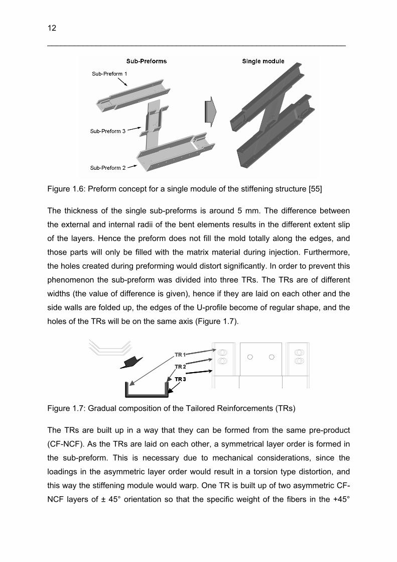
final preform of the total module is composed of three sub-preforms (Figure 1.6). The
construction is built up in a way that the fiber orientation and the layer order of the
single sub-preforms in the module is the same, hence production is cost effective and
preforming is simplified.
12
___________________________________________________________________
Figure 1.6: Preform concept for a single module of the stiffening structure [55]
The thickness of the single sub-preforms is around 5 mm. The difference between
the external and internal radii of the bent elements results in the different extent slip
of the layers. Hence the preform does not fill the mold totally along the edges, and
those parts will only be filled with the matrix material during injection. Furthermore,
the holes created during preforming would distort significantly. In order to prevent this
phenomenon the sub-preform was divided into three TRs. The TRs are of different
widths (the value of difference is given), hence if they are laid on each other and the
side walls are folded up, the edges of the U-profile become of regular shape, and the
holes of the TRs will be on the same axis (Figure 1.7).
TR 1
TR 2
TR 3
TR 1
TR 2
TR 3
TR 1
TR 2
TR 3
Figure 1.7: Gradual composition of the Tailored Reinforcements (TRs)
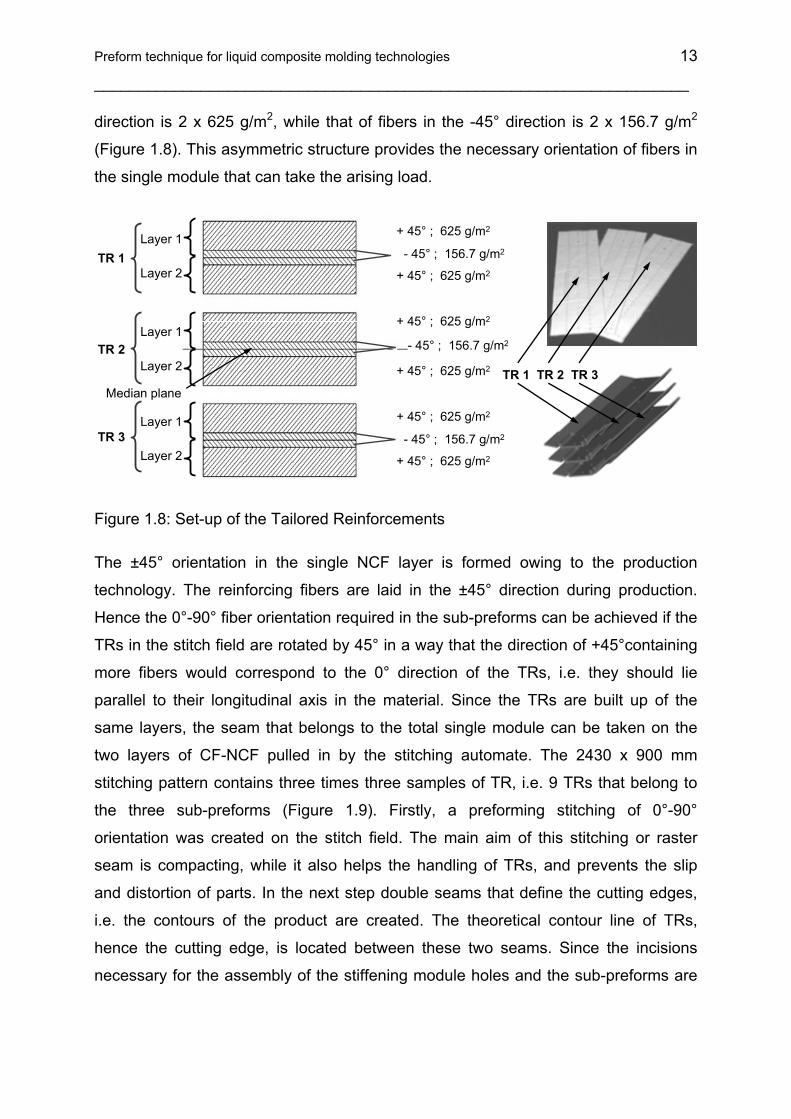
The TRs are built up in a way that they can be formed from the same pre-product
(CF-NCF). As the TRs are laid on each other, a symmetrical layer order is formed in
the sub-preform. This is necessary due to mechanical considerations, since the
loadings in the asymmetric layer order would result in a torsion type distortion, and
this way the stiffening module would warp. One TR is built up of two asymmetric CF-
NCF layers of ± 45° orientation so that the specific weight of the fibers in the +45°
Preform technique for liquid composite molding technologies 13
___________________________________________________________________
direction is 2 x 625 g/m2, while that of fibers in the -45° direction is 2 x 156.7 g/m2
(Figure 1.8). This asymmetric structure provides the necessary orientation of fibers in
the single module that can take the arising load.
TR 1 TR 2 TR 3
TR 1
TR 2
TR 3
+ 45° ; 625 g/m2
+ 45° ; 625 g/m2
+ 45° ; 625 g/m2
+ 45° ; 625 g/m2
+ 45° ; 625 g/m2
+ 45° ; 625 g/m2
- 45° ; 156.7 g/m2
- 45° ; 156.7 g/m2
- 45° ; 156.7 g/m2
Layer 1
Layer 2
Layer 1
Layer 2
Layer 1
Layer 2
Median plane
Figure 1.8: Set-up of the Tailored Reinforcements
The ±45° orientation in the single NCF layer is formed owing to the production
technology. The reinforcing fibers are laid in the ±45° direction during production.
Hence the 0°-90° fiber orientation required in the sub-preforms can be achieved if the
TRs in the stitch field are rotated by 45° in a way that the direction of +45°containing
more fibers would correspond to the 0° direction of the TRs, i.e. they should lie
parallel to their longitudinal axis in the material. Since the TRs are built up of the
same layers, the seam that belongs to the total single module can be taken on the
two layers of CF-NCF pulled in by the stitching automate. The 2430 x 900 mm
stitching pattern contains three times three samples of TR, i.e. 9 TRs that belong to
the three sub-preforms (Figure 1.9). Firstly, a preforming stitching of 0°-90°
orientation was created on the stitch field. The main aim of this stitching or raster
seam is compacting, while it also helps the handling of TRs, and prevents the slip
and distortion of parts. In the next step double seams that define the cutting edges,
i.e. the contours of the product are created. The theoretical contour line of TRs,
hence the cutting edge, is located between these two seams. Since the incisions
necessary for the assembly of the stiffening module holes and the sub-preforms are

14
___________________________________________________________________
already created during preforming in the reinforcing structure, their contours are also
fixed by the double contour seams.
+45°
0°
NCF layers with stitched compactionpattern
TailoredReinforcement
960
2430
1270Width of the NCF
Figure 1.9: Position of the Tailored Reinforcements (TRs) in the stitch field
During stitching preforming it is possible to create additional auxiliary seams. With
the help of these auxiliary seams reference points that can help the positioning of the
cutter in the next step can be formed in the stitch field (Figure 1.10). It is possible to
define a tighter seam raster during program planning, and this way a better stability
can be provided for the areas that are loaded in a greater extent during cutting and
when putting into the mold.
Base point
Contour stitch(Double stitch lines)
Higher compaction by closer stitching pattern
Fold mark supportedby stitching
Cutting line
Figure 1.10: Stitch types on the stitching field

Preform technique for liquid composite molding technologies 15
___________________________________________________________________
The tighter raster seam can result in a greater extent compacting, and hence can
ease the fitting of critical preform parts into the injection mold and the mold closure.
After forming the whole seam structure, the stitched field is transported further to the
cutter synchronized with the stitching machine. The table of the cutter is a vacuum
table and a transporter belt in one. A layer of air-permeable paper is laid on the
surface of this table, and then the stitched fabric is placed on it. Fixing the fabric with
vacuum is aided by the thin foil placed on the surface. With the help of the foil, the
vacuum affecting a large area holds down the stitched NCF to be cut efficiently. The
applied cutter has an offline camera matching system with the help of which the
reference point of the cutting head can be positioned exactly; hence the pre-
programmed cutting contour can be matched exactly with the real contours. This
positioning ensures that the cutting contours are located exactly between the double
seams bordering the contours. Fixing the reference points can be achieved with the
help of the already mentioned auxiliary stitches or the characteristic peaks of the
stitched field (Figure 1.11). Camera matching is enhanced because the textile can be
enlightened by UV waves in the visibility range of the camera. This way the auxiliary
threads or the UV-active, optical by bright stitching threads help the identification of
the reference points and the number of disturbing optical phenomenon can be
reduced.
Figure 1.11: Cut contour with matching points for the visual re-adjust of base points
The preforms are cut out with the already mentioned programmable cutter. Cutting is
carried out with a rotatable steel flying knife. This is the most common cutting method
in preform technology. Cutting can also be done with laser or ultrasound, or with
punching in case of simple, unchanged geometry and large scale production. Due to
16
___________________________________________________________________
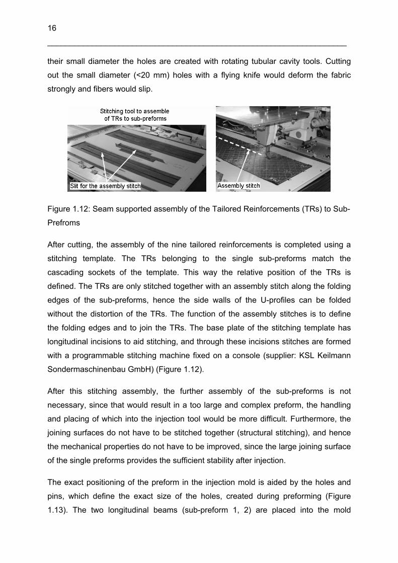
their small diameter the holes are created with rotating tubular cavity tools. Cutting
out the small diameter (<20 mm) holes with a flying knife would deform the fabric
strongly and fibers would slip.
Figure 1.12: Seam supported assembly of the Tailored Reinforcements (TRs) to Sub-
Prefroms
After cutting, the assembly of the nine tailored reinforcements is completed using a
stitching template. The TRs belonging to the single sub-preforms match the
cascading sockets of the template. This way the relative position of the TRs is
defined. The TRs are only stitched together with an assembly stitch along the folding
edges of the sub-preforms, hence the side walls of the U-profiles can be folded
without the distortion of the TRs. The function of the assembly stitches is to define
the folding edges and to join the TRs. The base plate of the stitching template has
longitudinal incisions to aid stitching, and through these incisions stitches are formed
with a programmable stitching machine fixed on a console (supplier: KSL Keilmann
Sondermaschinenbau GmbH) (Figure 1.12).
After this stitching assembly, the further assembly of the sub-preforms is not
necessary, since that would result in a too large and complex preform, the handling
and placing of which into the injection tool would be more difficult. Furthermore, the
joining surfaces do not have to be stitched together (structural stitching), and hence
the mechanical properties do not have to be improved, since the large joining surface
of the single preforms provides the sufficient stability after injection.
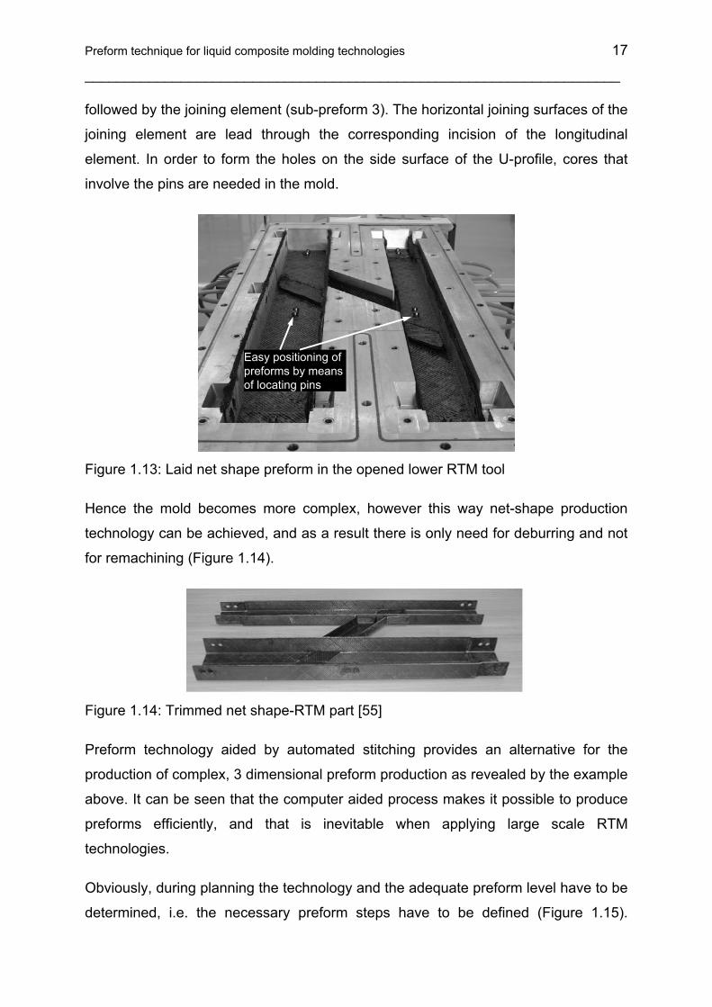
The exact positioning of the preform in the injection mold is aided by the holes and
pins, which define the exact size of the holes, created during preforming (Figure
1.13). The two longitudinal beams (sub-preform 1, 2) are placed into the mold
Preform technique for liquid composite molding technologies 17
___________________________________________________________________
followed by the joining element (sub-preform 3). The horizontal joining surfaces of the
joining element are lead through the corresponding incision of the longitudinal
element. In order to form the holes on the side surface of the U-profile, cores that
involve the pins are needed in the mold.
Easy positioning of preforms by means of locating pins
Figure 1.13: Laid net shape preform in the opened lower RTM tool
Hence the mold becomes more complex, however this way net-shape production
technology can be achieved, and as a result there is only need for deburring and not
for remachining (Figure 1.14).
Figure 1.14: Trimmed net shape-RTM part [55]
Preform technology aided by automated stitching provides an alternative for the
production of complex, 3 dimensional preform production as revealed by the example
above. It can be seen that the computer aided process makes it possible to produce
preforms efficiently, and that is inevitable when applying large scale RTM
technologies.
Obviously, during planning the technology and the adequate preform level have to be
determined, i.e. the necessary preform steps have to be defined (Figure 1.15).

18
___________________________________________________________________
Preforming above the necessary level makes a process more expensive due to the
derivative technological steps. On the other hand, if the preforms are not prepared
adequately, it makes placing into the mold difficult, hence this step will be more time
consuming, and the whole production will be more costly. Furthermore, during
planning it has to be decided whether absolute net-shape technology should be
applied when producing the part. In some cases, the final shape can be achieved
with remachining (e.g. drilling, milling) in a more cost-efficient way than with the
application of complex injection tools and a multi-step preform technology. TR
Sub
-pre
form
in-p
lane
asse
mbl
y
Fina
l Pre
form
Ass
embl
y(F
PA
)
Par
t cos
t
Total costs withoutpreforming
Total cost with preforming
Critical preforming effort
Pre
form
Out
-of p
lane
asse
mbl
y
Figure 1.15: Relation between manufacturing cost reduction and preforming effort
[51]
1.2 Philosophy of the stitching supported preform-LCM process chain
Quick placement of the preform into the mold, easy mounting, and fault free single
shot resin impregnation is an economical method of FRPC manufacturing. Preforms
manufactured within the mold tolerances reduce the mold placement time and also
avoid the possibility of resin channel formation. If the preform manufacturing is
performed by keeping the actual mold geometry and the tolerances in mind, then the
next process tasks are easier and quicker than the conventional methods. Starting
from the selection of textile material to the assembling of 2D preforms reduces the
total molding time. As the preforms are cut to the exact shape, fiber setting between
the molds can be avoided, thus there are limited difficulties in the mold closure. Again
the inserts and other locally strengthening or toughening elements can be placed at
Preform technique for liquid composite molding technologies 19
___________________________________________________________________
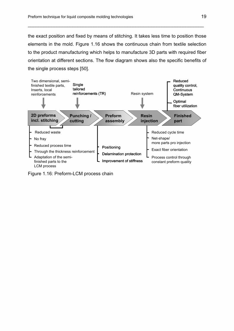
the exact position and fixed by means of stitching. It takes less time to position those
elements in the mold. Figure 1.16 shows the continuous chain from textile selection
to the product manufacturing which helps to manufacture 3D parts with required fiber
orientation at different sections. The flow diagram shows also the specific benefits of
the single process steps [50].
Positioning
Delamination protection
Improvement of stiffness
Preform assembly
Positioning
Delamination protection
Improvement of stiffness
Preform assembly
Single tailored reinforcements (TR)
Punching / cutting
Single tailored reinforcements (TR)
Punching / cutting
Optimal fiber utilization
Finishedpart
Reduced quality control,Continuous QM-System
Optimal fiber utilization
Finishedpart
Reduced quality control,Continuous QM-System
Reduced cycle timeNet-shape/ more parts pro injection
Exact fiber orientation
Resin system
Resininjection
Process control throughconstant preform quality
Reduced waste
No fray
Reduced process time
Adaptation of the semi-finished parts to the LCM process
Through the thickness reinforcement
Two dimensional, semi-finished textile parts, Inserts, local reinforcements
2D preforms incl. stitching
Figure 1.16: Preform-LCM process chain

20
___________________________________________________________________
2 Application of soluble bonding yarns to assemble 3D preform structures
Sometimes the predefined position and fixation of two dimensional reinforcing
structures cannot fulfill the requirements and the production of fixed 3 dimensional
preforms may also be necessary. Hence the preform design and the way it can be
handled and placed into the mold are important features. Placing into the mold
enhances a technological step if the size and geometry of the mold is the same as
that of the preform placed into it. These three dimensional pre-products can be
manufactured with three methods:
• direct preforming technologies
• with thermosetting or thermoplastic binder
• assembly and compaction using stitching technology
Direct textile technique processes, such as the Ford Programmable Preform Process
(F3P) [56], or the Programmable Powder Preform Process (P4) [57] can be applied
to manufacture preforms directly from fibrous reinforcing materials without any
intermediate textile industrial process [58]. The essence of the process is that the
fibrous material in the form of a roving is cut with a cutter-sprayer and mixer head.
The short fibers formed this way are mixed with the binder powder or fluid and are
pressed to the surface of the heated preform mold. The short fibers mixed with the
binder are kept on the surface until complete melting and cooling with the help of air
vacuumed through small capillaries in the mold. When the fibers fixed this way are
removed from the surface of the preform mold, a three dimensional preproduct that
provides a non-oriented, short fibrous reinforcement for composite parts can be
obtained.
When a thermoplastic powder binder material of low melting point is used, it is
spread on the surface with a roll or a spray jet. In case of thermosetting materials,
there is a possibility to spread the material evenly in the form of a solution. The
treated woven layers are put on each other and are heat treated; hence the binder
material is molten and cooled down. This is how the layers are adhered to each
other. This method makes it possible to shape textiles in three dimensions, since
they keep the original shape after cooling.

Application of soluble bonding yarns to assemble 3D preform structures 21
___________________________________________________________________
The third possibility to produce spatial preforms is the application of the stitching
technology already detailed in the first chapter. During stitching preform production
threads that melt at low temperature are necessary because then the two
dimensional sub-preforms can be fixed in a three dimensional form in a
thermoforming process and this way the step of placing the preform into the mold is
made significantly easier and quicker.
2.1 Application of bonding yarns in 3D preform manufacturing
The application of yarns made of fibers that melt at low temperature is already
widespread in the textile industry. The following experiments were carried out using
co-polyamide and co-polyester yarns of different melting points produced by EMS
Griltech (www.emsgriltech.com).
Thermoforming tests were completed on a biaxial ± 45° CF-NCF material, the
specific weight of which was 50 g/m2 (producer Saertex GmbH & Co. KG). Stitching
was carried out with a co-polyester yarn type Grilon KE-60 of 60°C melting point and
167 dtex linear density. The specimen in Figure 2.1 is composed of two 220 x 180
mm units that were fixed to each other with a 5 x 5 mm compacting seam.
Figure 2.1: Bonding thread stitched and thermoformed specimen (dry preform)
Compaction was carried out on a programmable stitching automat. The yarn strength
of the bobbin as well as that of the upper yarn was reduced significantly due to the
unfavourable mechanical properties of the yarn. Then a “T” shape was created by
cutting the two dimensional textile at the appropriate places. The preproduct
composed this way was heated after having been placed on a mold of adequate
22
___________________________________________________________________
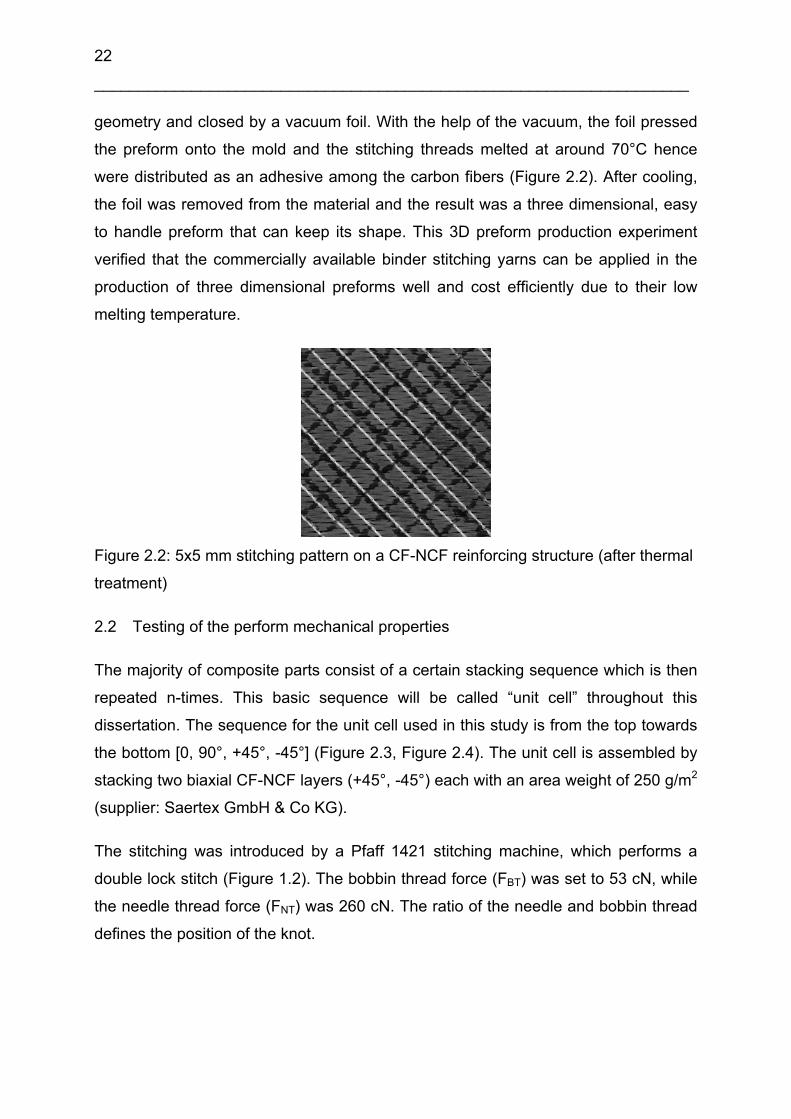
geometry and closed by a vacuum foil. With the help of the vacuum, the foil pressed
the preform onto the mold and the stitching threads melted at around 70°C hence
were distributed as an adhesive among the carbon fibers (Figure 2.2). After cooling,
the foil was removed from the material and the result was a three dimensional, easy
to handle preform that can keep its shape. This 3D preform production experiment
verified that the commercially available binder stitching yarns can be applied in the
production of three dimensional preforms well and cost efficiently due to their low
melting temperature.
Figure 2.2: 5x5 mm stitching pattern on a CF-NCF reinforcing structure (after thermal
treatment)
2.2 Testing of the perform mechanical properties
The majority of composite parts consist of a certain stacking sequence which is then
repeated n-times. This basic sequence will be called “unit cell” throughout this
dissertation. The sequence for the unit cell used in this study is from the top towards
the bottom [0, 90°, +45°, -45°] (Figure 2.3, Figure 2.4). The unit cell is assembled by
stacking two biaxial CF-NCF layers (+45°, -45°) each with an area weight of 250 g/m2
(supplier: Saertex GmbH & Co KG).
The stitching was introduced by a Pfaff 1421 stitching machine, which performs a
double lock stitch (Figure 1.2). The bobbin thread force (FBT) was set to 53 cN, while
the needle thread force (FNT) was 260 cN. The ratio of the needle and bobbin thread
defines the position of the knot.
Application of soluble bonding yarns to assemble 3D preform structures 23
___________________________________________________________________
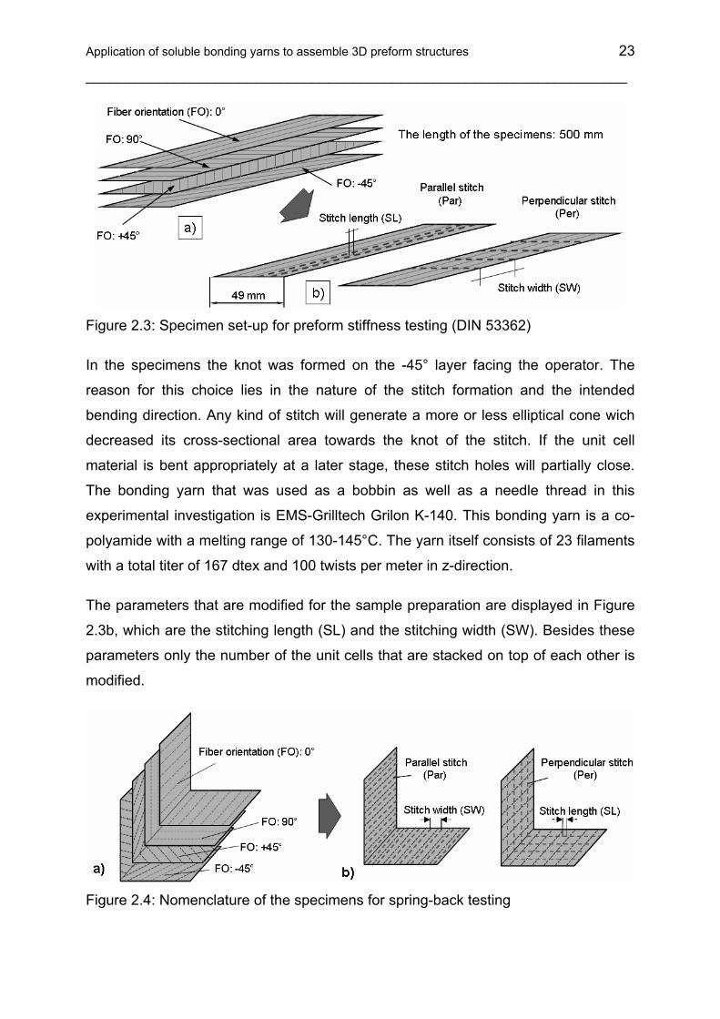
Figure 2.3: Specimen set-up for preform stiffness testing (DIN 53362)
In the specimens the knot was formed on the -45° layer facing the operator. The
reason for this choice lies in the nature of the stitch formation and the intended
bending direction. Any kind of stitch will generate a more or less elliptical cone wich
decreased its cross-sectional area towards the knot of the stitch. If the unit cell
material is bent appropriately at a later stage, these stitch holes will partially close.
The bonding yarn that was used as a bobbin as well as a needle thread in this
experimental investigation is EMS-Grilltech Grilon K-140. This bonding yarn is a co-
polyamide with a melting range of 130-145°C. The yarn itself consists of 23 filaments
with a total titer of 167 dtex and 100 twists per meter in z-direction.
The parameters that are modified for the sample preparation are displayed in Figure
2.3b, which are the stitching length (SL) and the stitching width (SW). Besides these
parameters only the number of the unit cells that are stacked on top of each other is
modified.
Figure 2.4: Nomenclature of the specimens for spring-back testing

24
___________________________________________________________________
To develop their adhesive effect the yarns need to be brought into the melting range
of the thermoplastic yarn. For the purpose of maintaining a constant compaction
pressure as well as a repeatable temperature profile to melt the yarn, all thermal
treatments have been performed with the set-up displayed in Figure 2.5.
Insulation
Stitched fabric layers
Thermo-couples
Aluminum L-profile600 mm 80 x 6 mmDIN 1771 (cold)
AluminumL- profile 600 mm,60 x 6 mmDIN 1771 (hot)
F
Insulation
Stitched fabric layers
Thermo-couples
Aluminum L-profile600 mm 80 x 6 mmDIN 1771 (cold)
AluminumL- profile 600 mm,60 x 6 mmDIN 1771 (hot)
F
Figure 2.5: Set-up for the thermal consolidation of the stitched samples
The thermal treatment consisted of placing the unit cells on top of the larger L-profile
and prefixing them there with small stripes of adhesive tape. Then the top portion, the
square block and the small L-profile are taken out of the 250°C hot oven and are
placed on top of the unit cells (stitched layer fabric).
Figure 2.6: Thermal process of the consolidation
The temperature profile for the thermal treatment can be seen in Figure 2.6. It is
evident that the complete stack reaches a temperature above the lower melting
Application of soluble bonding yarns to assemble 3D preform structures 25
___________________________________________________________________
range of the bonding yarn, since the thermocouple is positioned on the outer side of
the L-profile, covered by the insulation.
2.3 Experimental procedure
The aim of the experimental procedure was to investigate the influence of the
stitching process parameters on the characteristic of the preform. Firstly the preform
characteristic is defined by measuring the perform bending stiffness, the spring back
angle, and the restoring force for stitched an unstitched CF-NCF (Saertex).
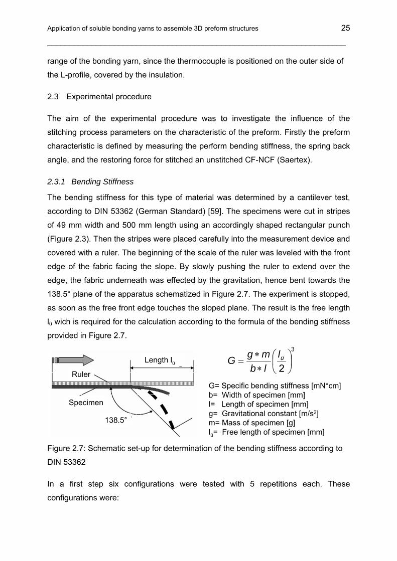
2.3.1 Bending Stiffness
The bending stiffness for this type of material was determined by a cantilever test,
according to DIN 53362 (German Standard) [59]. The specimens were cut in stripes
of 49 mm width and 500 mm length using an accordingly shaped rectangular punch
(Figure 2.3). Then the stripes were placed carefully into the measurement device and
covered with a ruler. The beginning of the scale of the ruler was leveled with the front
edge of the fabric facing the slope. By slowly pushing the ruler to extend over the
edge, the fabric underneath was effected by the gravitation, hence bent towards the
138.5° plane of the apparatus schematized in Figure 2.7. The experiment is stopped,
as soon as the free front edge touches the sloped plane. The result is the free length
lü wich is required for the calculation according to the formula of the bending stiffness
provided in Figure 2.7.
G= Specific bending stiffness [mN*cm] b= Width of specimen [mm]l= Length of specimen [mm]g= Gravitational constant [m/s2]m= Mass of specimen [g]lü= Free length of specimen [mm]
3
2⎟⎠⎞
⎜⎝⎛
∗∗
= üllbmgG
Ruler
Specimen
Length lü
138.5°
Figure 2.7: Schematic set-up for determination of the bending stiffness according to
DIN 53362
In a first step six configurations were tested with 5 repetitions each. These
configurations were:

26
___________________________________________________________________
• Unmodifed biaxial CF-NCF [0°,90°]
• Unmodifed biaxial CF-NCF [+45°, -45°]
• 1 unit cell [0°,90°,+45°,-45°], stitching length 2 mm (SL2), stitching width 5 mm
(SW05), without thermally treatment
• 1 unit cell, stitching length 4 mm (SL4), stitching width 10 mm (SW10), without
thermally treatment
• 1 unit cell, stitching length 2 mm (SL2), stitching width 5 mm (SW05),
thermally treated
• 1 unit cell, stitching length 4 mm (SL4), stitching width 10 mm (SW10),
thermally treated
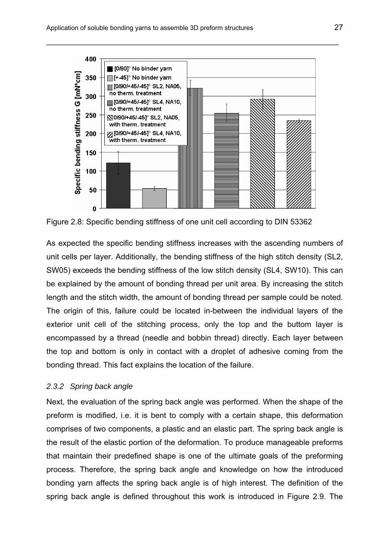
The results of this baseline test are displayed in Figure 2.8. It is obvious and easy to
understand that the bending stiffness of the biaxial CF-NCF [0°,90°] is superior to the
biaxial CF-NCF [+45°,-45°], since the fibers of the 0° direction extend parallel to the
500 mm edge. Once two layers of biaxial fabrics are stitched together to form a unit
cell, the bending stiffness shows an effect concerning the combination of stitching
length (SL) and stitching width (SW).
The combination of SL2 with SW05 is exceeding the measured values of the SL4
SW10 combination. The tension of the stitch information is locally “binding” the fiber
stacks together, thus restraining the movement of the fibers relative to each other,
and hence a higher bending stiffness arises. Additionally, the number of seams per
width of the samples supports the development towards higher bending stiffness.
The third part of columns in Figure 2.8 reassembles the result of the bending
stiffness after the stitched unit cell samples were thermally treated as mentioned
previously. Therefore, the thermoplastic thread has molten and adhered to the
carbon fibers surrounding the thread. The reason for the decrease in the bending
stiffness compared with the results of thermally untreated samples can be explained
by the fact that a part of the thread tension has been relieved during the melting
process. Obviously, the thread tension was higher than the compaction pressure
applied during the thermal treatment.
Application of soluble bonding yarns to assemble 3D preform structures 27
___________________________________________________________________
Figure 2.8: Specific bending stiffness of one unit cell according to DIN 53362
As expected the specific bending stiffness increases with the ascending numbers of
unit cells per layer. Additionally, the bending stiffness of the high stitch density (SL2,
SW05) exceeds the bending stiffness of the low stitch density (SL4, SW10). This can
be explained by the amount of bonding thread per unit area. By increasing the stitch
length and the stitch width, the amount of bonding thread per sample could be noted.
The origin of this, failure could be located in-between the individual layers of the
exterior unit cell of the stitching process, only the top and the buttom layer is
encompassed by a thread (needle and bobbin thread) directly. Each layer between
the top and bottom is only in contact with a droplet of adhesive coming from the
bonding thread. This fact explains the location of the failure.
2.3.2 Spring back angle
Next, the evaluation of the spring back angle was performed. When the shape of the
preform is modified, i.e. it is bent to comply with a certain shape, this deformation
comprises of two components, a plastic and an elastic part. The spring back angle is
the result of the elastic portion of the deformation. To produce manageable preforms
that maintain their predefined shape is one of the ultimate goals of the preforming
process. Therefore, the spring back angle and knowledge on how the introduced
bonding yarn affects the spring back angle is of high interest. The definition of the
spring back angle is defined throughout this work is introduced in Figure 2.9. The

28
___________________________________________________________________
deviation of the original geometry, which was a right angle, can be seen in the
schematic graphic.
Spring back angle
Ideal geometry
Geometry after preforming
Spring back angle
Ideal geometry
Geometry after preforming
Figure 2.9: Effect of spring back after the pre-compaction step
The results of the investigations of the spring back angle are shown in Figure 2.10.
The first important result is when the amount of unit cell is kept constant, there is a
significant difference between the perpendicular and parallel stitching direction for all
samples and stitching parameters.
Figure 2.10: Influence of the number of unit cells per preform on the spring back
angle
The perpendicular stitching direction, which is the bending line of the L-shaped
geometry (Figure 2.4), always exhibits smaller spring back angles than the parallel
direction. If the number of unit cells are kept constant and only the stitch length
between two identical patterns is varied from 4 mm to 2 mm, the spring back angle is
also reduced in every case. Similarly, the reduction of the stitching width from 10 mm

Application of soluble bonding yarns to assemble 3D preform structures 29
___________________________________________________________________
to 5 mm results in a reduction of the spring back angle. The increase of the amount
of unit cells per sample also affects the spring back angle positively. This is
reasonable, since the stitching between the unit cells provides a possibility to transfer
the existing shear loads from the one layer to the next, and this was not possible
before.
2.3.3 Restoring force
This experiment helps to define the restoring force required to eliminate the spring
back angle. The same specimens was taken which were used for the spring back
testing were examined in the following tests. The experimental set-up of the restoring
force testing is shown in Figure 2.11. One side of the L-shaped specimen is fixed on
the base plate with a metallic clamping. With help of a guide roller - which guides the
thin PA fiber fixed on the free site of the specimen - and the sensitive spring scale it
was possible to measure the restoring force required for the elimination of the spring
back angle of the specimens after thermoforming.
Figure 2.12 shows that the preforms with 2 mm stitch length and 5 mm stitch width,
i.e. the specimens with the highest stitch density, need the highest restoring force. It
is also observed that the preforms with perpendicular stitch are more stable or stiff,
than the parallel stitched specimens with the same stitch density.
Figure 2.11: Experimental setup for the measurement of restoring force on
compacted layers
Therefore the parallel stitched specimens with 4 mm stitch length and 10 mm stitch
width, i.e. with the lowest stitch density, need the lower force to bring it back to the

30
___________________________________________________________________
right angle position. Additionally, it is clearly observed that the specimens with three
layers are in all cases stiffer than the specimens with two layers.
0
50
100
150
200
250
Rüc
kbie
gekr
aft a
uf 9
0° [m
N]
Variation B_2mm Stichlänge_5mmNahtabstand_Naht senkrecht_2PaketeVariation H_2mm Stichlänge_5mmNahtabstand_Naht parallel_2PaketeVariation E_2mm Stichlänge_10mmNahtabstand_Naht senkrecht_2PaketeVariation K_2mm Stichlänge_10mmNahtabstand_Naht parallel_2PaketeVariation N_4mm Stichlänge_5mmNahtabstand_Naht senkrecht_2PaketeVariation T_4mm Stichlänge_5mmNahtabstand_Naht parallel_2PaketeVariation Q_4mm Stichlänge_10mmNahtabstand_Naht senkrecht_2PaketeVariation W_4mm Stichlänge_10mmNahtabstand_Naht parallel_2Pakete
0
50
100
150
200
250
Rüc
kbie
gekr
aft a
uf 9
0° [m
N]
Variation C_2mm Stichlänge_5mmNahtabstand_Naht senkrecht_3PaketeVariation I_2mm Stichlänge_5mmNahtabstand_Naht parallel_3PaketeVariation F_2mm Stichlänge_10mmNahtabstand_Naht senkrecht_3PaketeVariation L_2mm Stichlänge_10mmNahtabstand_Naht parallel_3PaketeVariation O_4mm Stichlänge_5mmNahtabstand_Naht senkrecht_3PaketeVariation U_4mm Stichlänge_5mmNahtabstand_Naht parallel_3PaketeVariation R_4mm Stichlänge_10mmNahtabstand_Naht senkrecht_3PaketeVariation X_4mm Stichlänge_10mmNahtabstand_Naht parallel_3Pakete
70
90
110
130
150
170
190
210
2 layers 3 layers
Res
torin
g fo
rce
[mN
](d
iscr
ete
valu
es)
SL2_SW05_per
SL2_SW05_par
SL4_SW10_par
Trend lines:
Figure 2.12: Experimentally determined restoring force of compacted layers
Quantitative measurement methods were worked out to reveal the mechanical
properties of the fusible thread stitched three-dimensional preforms. These
measurement methods indicate the effect of the orientation and density of the
stitching in the reinforcing structure after thermal treatment. The three basic
properties of the thermoformed preforms (specific bending stiffness, spring back
angle, and restoring force) are important to evaluate the processability and handling
of the preforms. In case of ideal properties the specific bending stiffness is high, the
spring back angle and the restoring force are low.
2.4 Solubility tests of Grilon threads in different resin systems
The next important topic of the investigations is to examine the solubility properties of
different stitching yarns for 3D preforming. This property of the stitching thread is
necessary because the presence of thermoplastic stitching yarns can influence the
mechanical properties of thermoset composites in case they are prepared with the
stitching technology (Figure 2.13). Furthermore, the size of the stitch holes produced
during stitching also has an impact on the mechanical properties but this
unfavourable effect can be eliminated if the stitching yarns are dissolved.
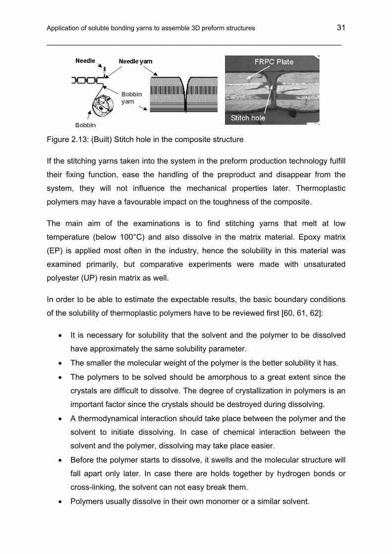
Application of soluble bonding yarns to assemble 3D preform structures 31
___________________________________________________________________
Figure 2.13: (Built) Stitch hole in the composite structure
If the stitching yarns taken into the system in the preform production technology fulfill
their fixing function, ease the handling of the preproduct and disappear from the
system, they will not influence the mechanical properties later. Thermoplastic
polymers may have a favourable impact on the toughness of the composite.
The main aim of the examinations is to find stitching yarns that melt at low
temperature (below 100°C) and also dissolve in the matrix material. Epoxy matrix
(EP) is applied most often in the industry, hence the solubility in this material was
examined primarily, but comparative experiments were made with unsaturated
polyester (UP) resin matrix as well.
In order to be able to estimate the expectable results, the basic boundary conditions
of the solubility of thermoplastic polymers have to be reviewed first [60, 61, 62]:
• It is necessary for solubility that the solvent and the polymer to be dissolved
have approximately the same solubility parameter.
• The smaller the molecular weight of the polymer is the better solubility it has.
• The polymers to be solved should be amorphous to a great extent since the
crystals are difficult to dissolve. The degree of crystallization in polymers is an
important factor since the crystals should be destroyed during dissolving.
• A thermodynamical interaction should take place between the polymer and the
solvent to initiate dissolving. In case of chemical interaction between the
solvent and the polymer, dissolving may take place easier.
• Before the polymer starts to dissolve, it swells and the molecular structure will
fall apart only later. In case there are holds together by hydrogen bonds or
cross-linking, the solvent can not easy break them.
• Polymers usually dissolve in their own monomer or a similar solvent.

32
___________________________________________________________________
• Since epoxy resins and especially their hardeners are strongly polar, the TP
polymer to be solved should also be polar. There are some suitable materials
such as PEI (polyether-imide), PES (polyether-sulphone) and PSU
(polysulphone) [63, 64, 65, 66, 67, 68, 69, 70, 71]. The disadvantage of these
materials is that their glass transition temperature (TG) is high (ca. 200°C).
This effect is negative for the 3D performing applications because the sizing of
the reinforcing fibers can be degraded at this temperature. This materials
cannot be applied as binder yarns due to the economical reasons.
• Since Co-PA and Co-PET are used as binder yarns commercially, a strongly
polar resin system is necessary for solubility.
• The RTM6 system often applied in composite technologies has an acid
anhydride hardener (producer: HEXCELL, TG ca.: 210°C). A similar system is
commercially available now with amine hardener which is of stronger polarity,
hence Co-PA and Co-PET fibers are more likely to dissolve in them. The
disadvantage of the amine hardener resins is that their TG is lower, around
136°C.
• The examinations can be extended to the range of biodegradable polymers of
low melting point because they have CONH (amide) and COO (ester) bonds,
which even are polar. Therefore, the related polymers can be dissolved in the
resin matrix more smoothly. Such materials are e.g. polycaprolactone or
polyvinyl-alcohol.
Since a basic criterion of dissolving is that the solvent and the material to be solved
have almost the same solubility parameter, the first step is to examine this condition.
2.4.1 Solubility of polymer materials
The interaction between amorphous polymers and liquids is similar to that between
two liquids. It is known that the free enthalpy, i.e. the Gibbs potential (G) has to
decrease in natural processes. Solubility is also present if the free enthalpy of mixing,
∆G, is negative.
It is known from thermodynamics [72] that
∆G = ∆H - T∆S (2.1)

Application of soluble bonding yarns to assemble 3D preform structures 33
___________________________________________________________________
where H [J] is enthalpy (U + PV), T [K] is absolute temperature, and S [J/K] is
entropy. The U [J] is internal energy, P [Pa] is pressure, and V [m3] is volume.
The entropy of mixing is positive in non-water systems; hence the sign and value of
∆G are determined primarily by ∆H, the heat of mixing. If there is any exothermic
interaction between the liquid and the polymer, ∆H is negative, the system warms up
and the polymer dissolves. If the chemical interaction is endothermic, ∆H is positive,
the system cools down, and the value of ∆H determines whether the free energy
calculated from Equation (2.1) is positive or negative, i.e. whether dissolving takes
place. Polymers dissolve in two steps. Firstly, the solvent diffuses into the polymer
that swells as a result, then the molecules have to diffuse out of the polymer and
dissolving takes place [73].
2.4.2 Solubility parameter
If the interaction between the polymer and the solvent is only a result of dispersion
forces, ∆H is positive and its value determines whether dissolution takes place.
According to Hildebrand and Scott (1950) the heat of mixing for a volume unit is [73]:
∆H = v1 v2 (δ1-δ2)2 (2.2)
where v is the volume fraction, index 1 refers to the solvent and index 2 to the
polymer, while δ is the solubility parameter, which is the square root of the cohesion
energy density (CED). The equation reaches its minimum when the values of δ1 and
δ2 are almost the same and in this case ∆G is maximal in absolute value. This means
that the solubility parameter of the solvent and the polymer to be solved has to be
approximately the same so that dissolution can start. Although the polymers used by
us are copolymers, first of all the solubility parameters of basic polymers were
considered. Table 2.1 contains the solubility parameters of polymers important in the
experiments.
Table 2.1: Solubility parameters of polymers
Polymer Solubility parameter δ [(J/cm3)1/2] Polyethylene terephthalate (PET) 19.9-21.9
Polyamide (PA) 27.8-28.0

34
___________________________________________________________________
Polycaprolactone (PCL) 19.1-19.3 Polyvinyl-alcohol (PVAL) 25.8-29.1 Epoxy resin (EP) 23.3-24.9 Unsaturated Polyester (UP) 22.2 Grilon MS (Polyhydroxyether) 22,3
2.5 Results of the solubility tests
The tests completed at different temperatures are denoted by “X” in Table 2.2. Before
the experiments the stitching threads were rolled on a 20 mm x 30 mm alumina
frame except for the RTM6 technology. These bobbins were placed into a small
holder filled with the matrix and resin was cured at the temperature shown in Table
2.2.
After curing of the resin, cross sections of the threads and resin were cut and light
microscopic examination was carried out on them. The polished samples were
investigated at different magnifications. The essence of experiments was to examine
the interface of thermoplastic stitching threads and resin.
Table 2.2: Solubility test of Grilon threads in different resin systems
XX-X-XGrilon MS (Polyhydroxyether)
XX-X--Polyvinyil-alcohol (PVAL)
XX-X-XPolycaprolactone (PCL)
XX-X--Grilon K-140 (Co-PA)
XX-X--Grilon K-85 (Co-PA)
XXXXXXGrilon KE-60 (Co-PET)
80 °C40 °CRT40 °CRTRTM6
EPUPResin(Curing temperature)
SolubilityBinder polymer yarn
XX-X-XGrilon MS (Polyhydroxyether)
XX-X--Polyvinyil-alcohol (PVAL)
XX-X-XPolycaprolactone (PCL)
XX-X--Grilon K-140 (Co-PA)
XX-X--Grilon K-85 (Co-PA)
XXXXXXGrilon KE-60 (Co-PET)
80 °C40 °CRT40 °CRTRTM6
EPUPResin(Curing temperature)
SolubilityBinder polymer yarn
2.5.1 Solubility test of co-polyester (Grilon KE-60) polymer in different resin systems
Firstly, co-polyester type Grilon KE-60 was examined in unsaturated polyester (UP)
resin (Figure 2.14). Figure 2.14 reveals that the filaments in the stitching thread partly
fused in the resin. The reason for this phenomenon is the exothermic effect of the UP
resin cured at room temperature. In case of partial melting, sharp borders can be
found between the TP fibers and the matrix and that means no dissolving took place
in the system. In Figure 2.14 the lighter spots in the middle of the molten fibers show

Application of soluble bonding yarns to assemble 3D preform structures 35
___________________________________________________________________
materials shortage, i.e. cavitations formed during sample polishing. The reason is the
worse wear resistance of the TP material.
Zoom: 100xZoom: 100x
Zoom: 500xZoom: 500x
Figure 2.14: Solubility of Grilon KE-60 (co-PET) thread in UP resin at room
temperature
In the following cases fiber type KE-60 was examined in unsaturated polyester resin
at 40°C cross-linking temperature. Due to the repeated exothermic heat impacts the
fibers melted to a greater extent in this sample and the ratio of not completely molten,
pure TP fibers is smaller (revealed as white spots in the figures) than in the previous
case (see Figure 2.15). The phase boundaries between the two materials can be
distinguished well despite the temperature was higher and melting was more
complete.
Zoom: 100xZoom: 100x
Figure 2.15: Solubility of Grilon KE 60 (co-PET) thread in UP resin at 40°C
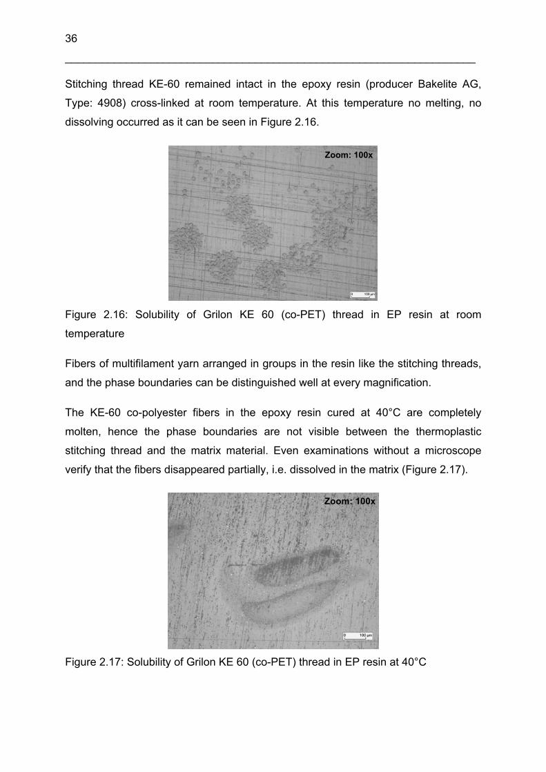
36
___________________________________________________________________
Stitching thread KE-60 remained intact in the epoxy resin (producer Bakelite AG,
Type: 4908) cross-linked at room temperature. At this temperature no melting, no
dissolving occurred as it can be seen in Figure 2.16.
Zoom: 100xZoom: 100x
Figure 2.16: Solubility of Grilon KE 60 (co-PET) thread in EP resin at room
temperature
Fibers of multifilament yarn arranged in groups in the resin like the stitching threads,
and the phase boundaries can be distinguished well at every magnification.
The KE-60 co-polyester fibers in the epoxy resin cured at 40°C are completely
molten, hence the phase boundaries are not visible between the thermoplastic
stitching thread and the matrix material. Even examinations without a microscope
verify that the fibers disappeared partially, i.e. dissolved in the matrix (Figure 2.17).
Zoom: 100x
Figure 2.17: Solubility of Grilon KE 60 (co-PET) thread in EP resin at 40°C

Application of soluble bonding yarns to assemble 3D preform structures 37
___________________________________________________________________
Owing to the exothermic processes in the resin, the temperature may rise above the
adjusted 40°C during cross-linking, and this way the melting point of material KE-60
(60°C) was approached.
When polyester fibers that melt at 60°C were placed in epoxy matrix cross-linked at
80°C all the fibers dissolved completely. In this case no evaluation can be made
based on light microscopic investigation. According to the non-microscopic visual
observations, only a refraction phenomenon experienced at a few spots in the matrix
refers to the presence of fibers with a melting point below the temperature of cross-
linking.
2.5.2 Solubility test of co-polyamide (Grilon K-85) polymer in epoxy resin
No signs of dissolving were experienced in fibers of 80°C melting point in epoxy resin
(producer Bakelite AG, Type: 4908) cross-linked at room temperature. The single
filaments arranged in groups correspondent to the stitching thread in the matrix. The
sharp phase boundaries revealed that no swelling process that may refer to melting
or dissolving started (Figure 2.18).
Zoom: 100xZoom: 100x
Figure 2.18: Solubility of Grilon K-85 (co-PA) thread in EP resin at room temperature
The filaments of these fibers fused in the resin cross-linked at 80°C and they
arranged in spots, not in the form of fibers, in the matrix. The cross-linking
temperature of the resin was the same as the melting point of the co-polyamide (K-
85) fibers but the presence of sharp phase boundaries referred to the fact that no
dissolving took place in the system (Figure 2.19).

38
___________________________________________________________________
Zoom: 100xZoom: 100x
Figure 2.19: Solubility of Grilon K-85 (co-PA) thread in EP resin at 80°C
2.5.3 Solubility test of co-polyamide (Grilon K-140) polymer in epoxy resin
Solubility tests were carried out on co-polyamide fibers type Grilon K-140 in epoxy
resin (producer Bakelite AG, Type: 4908) at room temperature and at 80°C which is
the proposed curing temperature of the resin. The fiber Grilon K-140 (melting
temperature: app. 140°C) shows no soluble properties in epoxy resin at room
temperature and at 80°C. The fibers keep intact in the resin during the curing
process.
2.5.4 Solubility tests of different polymers in RTM6 system
Co-polyester type Grilon KE-60 and co-polyamide type Grilon K-85 and Grilon K-140
fibers –already applied in previous experiments (see in Figure 2.1, and chapter 2.2)–
were used as binder yarns in these examinations. The melting point of yarn K-140
was around 140°C and its mechanical properties (maximum tensile stress and
elongation) were better than that of co-polyester (KE-60) of 60°C melting point. This
property makes it a good choice for applications in preform technologies for aircraft
applications.
For the following experiments a 2-layer NCF-CF (producer Saertex GmbH & Co. KG)
reinforcing system of 250 g/m2 weight per layer was stitched with TP stitching
threads. After the injection followed by cross-linking, polished samples from more
directions were made from the specimens. Injection was carried out with the VARI
process the parameters of which are listed in Table 2.3.

Application of soluble bonding yarns to assemble 3D preform structures 39
___________________________________________________________________
Table 2.3: Parameters of the RTM6 process
Process Parameter
Resin temperature for injection 90°C
Injection and tool temperature 120°C
Curing parameters cycle 1 160°C, 75 min
Curing parameter cycle 2 180°C, 120 min
This way the behaviour of stitching threads was studied in composites. A cross-
sectional and a top view picture were taken of the CF-laminates prepared in an
RTM6 process in both cases. Figure 2.20 reveals that the CF sheet stitched with a
thread type Grilon K-140 produced gas during the process of injection and cross-
linking and it was dispersed in the form bubbles on the surface of the laminate. The
stitch hole ellipse formed by the stitching thread can be examined at 25x
magnification well.
Knitting yarn
Molten thread
Stitch hole ellipse
Gas bubbles Zoom: 25x
Knitting yarn
Molten thread
Stitch hole ellipse
Gas bubbles Zoom: 25x
Co-PA binder thread
Knitting yarn
Gas bubbles
Zoom: 200x
Co-PA binder thread
Knitting yarn
Gas bubbles
Zoom: 200x
Figure 2.20: Solubility of Grilon K-140 (co-PA) thread in an RTM6 system (top view)
The black line on the left side in Figure 2.20 shows the polyester knitting yarns.
Despite the dissolution of fibers, the higher magnification revealed the sharp phase
boundaries of the TP fiber and the matrix yarn that was introduced to the system
during the production of CF-NCF. The holes, i.e. stitching points, formed by the 2 mm
long stitches in the reinforcing system are well visible in the sectional image in Figure
2.21.
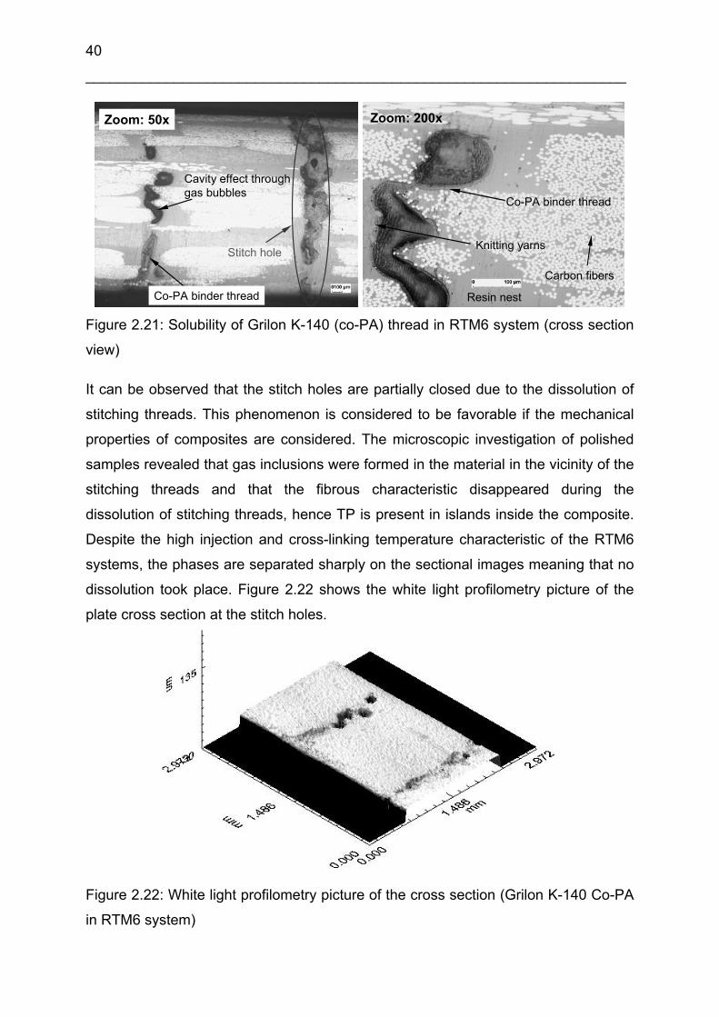
40
___________________________________________________________________
Cavity effect throughgas bubbles
Stitch hole
Co-PA binder thread
Zoom: 50x
Cavity effect throughgas bubbles
Stitch hole
Co-PA binder thread
Zoom: 50x
Knitting yarns
Co-PA binder thread
Carbon fibers
Resin nest
Zoom: 200x
Knitting yarns
Co-PA binder thread
Carbon fibers
Resin nest
Zoom: 200x
Figure 2.21: Solubility of Grilon K-140 (co-PA) thread in RTM6 system (cross section
view)
It can be observed that the stitch holes are partially closed due to the dissolution of
stitching threads. This phenomenon is considered to be favorable if the mechanical
properties of composites are considered. The microscopic investigation of polished
samples revealed that gas inclusions were formed in the material in the vicinity of the
stitching threads and that the fibrous characteristic disappeared during the
dissolution of stitching threads, hence TP is present in islands inside the composite.
Despite the high injection and cross-linking temperature characteristic of the RTM6
systems, the phases are separated sharply on the sectional images meaning that no
dissolution took place. Figure 2.22 shows the white light profilometry picture of the
plate cross section at the stitch holes.
Figure 2.22: White light profilometry picture of the cross section (Grilon K-140 Co-PA
in RTM6 system)
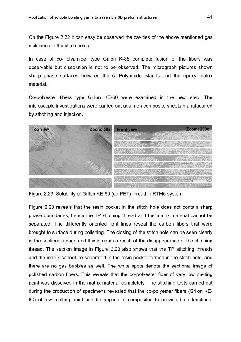
Application of soluble bonding yarns to assemble 3D preform structures 41
___________________________________________________________________
On the Figure 2.22 it can easy be observed the cavities of the above mentioned gas
inclusions in the stitch holes.
In case of co-Polyamide, type Grilon K-85 complete fusion of the fibers was
observable but dissolution is not to be observed. The micrograph pictures shown
sharp phase surfaces between the co-Polyamide islands and the epoxy matrix
material.
Co-polyester fibers type Grilon KE-60 were examined in the next step. The
microscopic investigations were carried out again on composite sheets manufactured
by stitching and injection.
Zoom: 50xTop view
Zoom: 200xFront view
Figure 2.23: Solubility of Grilon KE-60 (co-PET) thread in RTM6 system
Figure 2.23 reveals that the resin pocket in the stitch hole does not contain sharp
phase boundaries, hence the TP stitching thread and the matrix material cannot be
separated. The differently oriented light lines reveal the carbon fibers that were
brought to surface during polishing. The closing of the stitch hole can be seen clearly
in the sectional image and this is again a result of the disappearance of the stitching
thread. The section image in Figure 2.23 also shows that the TP stitching threads
and the matrix cannot be separated in the resin pocket formed in the stitch hole, and
there are no gas bubbles as well. The white spots denote the sectional image of
polished carbon fibers. This reveals that the co-polyester fiber of very low melting
point was dissolved in the matrix material completely. The stitching tests carried out
during the production of specimens revealed that the co-polyester fibers (Grilon KE-
60) of low melting point can be applied in composites to provide both functions:

42
___________________________________________________________________
Hence they can be binder materials and they can also dissolve in the resin in RTM6
systems at high injection temperature.
2.5.5 Solubility test of polycaprolactone and polyvinyl-alcohol (biodegradable
polymers) in different resin systems
Solubility tests were carried out on two different biodegradable polymer materials
(polycaprolactone, and polyvinyl-alcohol). It has been presumed that the polymers
are soluble in epoxy resin because of their affinitative chemical structure to the epoxy
resin. This analogy is basically the ester bond in the polymers and therethrough the
polar property. After the observations the polymers are no soluble in the epoxy resin.
In case of polycaprolactone at room temperature in epoxy and in UP resin no
solubility or swelling was observable. At 80°C in epoxy resin and in RTM6 resin at
120°C the polymer is temporarily swollen, and the color of the TP polymer is changed
with the higher temperature but after cooling sharp phase interfaces were observable
between the polycaprolactone and the cured epoxy polymer.
The polyvinyl-alcohol shows also no soluble properties in UP and EP resin. In this
case no changes were observable on the polymer structure or color.
2.5.6 Solubility test of Grilon MS polymer in different resin systems
The examinations of the recently developed Grilon MS (matrix soluble) threads
(supplier: EMS-CHEMIE AG) revealed their good solubility properties. Due to the low
melting point (ca. 80°C) of the polymer (polyhydroxyether), it can be applied well in
three dimensional preform technologies. Forming becomes economic this way since
the heat treatment of the stitching threads does not require high temperature.
Furthermore, stitching tests proved that the thread has the mechanical properties
necessary for stitching technologies (tensile stress and elongation). Since the
polymer has similar morphological properties to epoxy, our assumption was that the
thread can be solved well both in epoxy and UP resins.
Primarily, the polymer was examined in RTM6 resins at 120°C. The Grilon MS thread
was reeled on an alumina frame and was placed into a beaker filled with epoxy resin
later (Figure 2.24). The resin started to cross-link at 120°C, and was completely
cross-linked at 140°C.

Application of soluble bonding yarns to assemble 3D preform structures 43
___________________________________________________________________
t = 10min, T = 120°C t = after curing, (T = 140°C)t = 0 min, T = RT t = 10min, T = 120°C t = after curing, (T = 140°C)t = 0 min, T = RT Figure 2.24: Solubility test on Grilon MS thread in RTM6 resin
It can be seen in Figure 2.24 well that the threads already revealed good solubility
properties in the tenth minute, and after the complete cross-linking, no Grilon MS
yarn was present in the resin. Simple optical examinations prove the good solubility
of polyhydroxyether in epoxy resin at a temperature above the melting point of the
polymer. This property could already be predicted since the solubility parameter of
the material is very close to that of epoxy. The solubility tests of Grilon MS stitching
threads revealed that it was not soluble in epoxy resin if injection took place at room
temperature. In this case a carbon woven fabric was stitched with the thread, and
solubility was examined on micrographs of stitch hole sections.
The section of the composite plate injected and cross-linked at room temperature
exhibits the undamaged threads in the stitch holes as well (Figure 2.25).
Zoom: 50x
Figure 2.25: Micrograph picture of a stitch hole in a CF-EP composite structure
(Grilon MS, injection temperature: room temperature)
The thread type Grilon MS shown no soluble properties in epoxy resin at 80°C. The
stitching thread is partially melted, but no dissolution was observable.
The stitched CF woven fabric was also injected with RTM6 resin. The resin was
cross-linked at 140°C after injection at 120°C. The section image of the composite
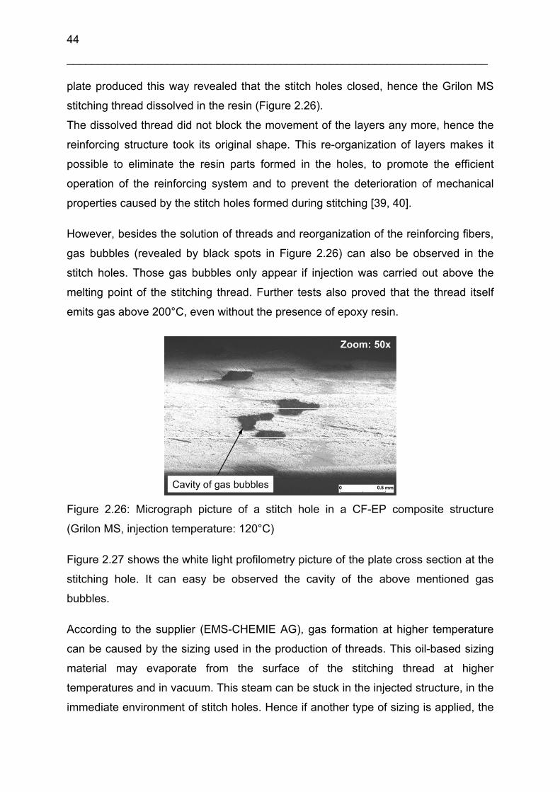
44
___________________________________________________________________
plate produced this way revealed that the stitch holes closed, hence the Grilon MS
stitching thread dissolved in the resin (Figure 2.26).
The dissolved thread did not block the movement of the layers any more, hence the
reinforcing structure took its original shape. This re-organization of layers makes it
possible to eliminate the resin parts formed in the holes, to promote the efficient
operation of the reinforcing system and to prevent the deterioration of mechanical
properties caused by the stitch holes formed during stitching [39, 40].
However, besides the solution of threads and reorganization of the reinforcing fibers,
gas bubbles (revealed by black spots in Figure 2.26) can also be observed in the
stitch holes. Those gas bubbles only appear if injection was carried out above the
melting point of the stitching thread. Further tests also proved that the thread itself
emits gas above 200°C, even without the presence of epoxy resin.
Zoom: 50x
Cavity of gas bubbles
Figure 2.26: Micrograph picture of a stitch hole in a CF-EP composite structure
(Grilon MS, injection temperature: 120°C)
Figure 2.27 shows the white light profilometry picture of the plate cross section at the
stitching hole. It can easy be observed the cavity of the above mentioned gas
bubbles.
According to the supplier (EMS-CHEMIE AG), gas formation at higher temperature
can be caused by the sizing used in the production of threads. This oil-based sizing
material may evaporate from the surface of the stitching thread at higher
temperatures and in vacuum. This steam can be stuck in the injected structure, in the
immediate environment of stitch holes. Hence if another type of sizing is applied, the

Application of soluble bonding yarns to assemble 3D preform structures 45
___________________________________________________________________
stitching thread can be used in 3D performs, and this way in the production of FRCP
parts.
Figure 2.27: White light profilometry picture of the plate cross section at the stitch
hole (Grilon MS in RTM6 system)
Since the solubility parameter of Grilon MS stitching thread (Table 2.1) is almost the
same as that of unsaturated polyester resin, the following tests focused on the
solubility in this material. Despite of this analogy the examinations revealed that the
stitching thread cannot be solved in UP resins at room temperature. Although the
exothermal cross-linking of the resin results in a higher temperature that can be
enough theoretically for the solution of the stitching threads, this temperature is only
reached after gelation of the resin that prevents the solution of the thread.
Table 2.4 summarizes the results of the observations during the experiments. The
results show that using soluble binder stitching threads is most useful at high
temperatures in RTM6 processes. Even in this case the application of
polyhydroxyether and co-polyester fibers of low temperature is the best but its impact
on the mechanical properties of composites after dissolution is not investigated within
this dissertation. Hence the Grilon MS stitching thread can only be dissolved in epoxy
resins around or above its melting point.

46
___________________________________________________________________
Nevertheless the most important result of the preforming and solubility investigations
verified that it is possible to find a thermoplastic polymer yarn which can be used for
3D preforming through its low melting temperature and good solubility properties in
epoxy resin. Through the dissolution of the stitching yarns the stitch holes can be
closed in the reinforcing structure during the injection and this effect can improve the
mechanical properties of the composite material.
Table 2.4: Solubility results of different TP polymers in different resin systems
The fibers are completely disappeared in the resin
No dissolution, the fibers are partially melted
No dissolution, the fibers are intact
No dissolution, the fibers are intact
Grilon MS (Polyhydroxyether)
No dissolution, the fibers are intact (crystalline PVAL)
No dissolution, the fibers are intact
No dissolution, the fibers are intact
Polyvinyl-alcohol (PVAL)
Complete fusion of the polymer, dissolution is not to be observed, sharp phase surfaces
No dissolution, temporary bulking at 80°C, the polymer stay intact
No dissolution, the fibers are intact.
No dissolution, the fibers are intact
Polycaprolactone (PCL)
No dissolution, the fibers are fused, but gas bubbles are observed in the stitch holes
No dissolution, the fibers are intact
No dissolution, the fibers are intact
Grilon K-140 (Co-polyamide)
Complete fusion of the fibers, dissolution is not to be observed, sharp phase surfaces
Fusion of the fibers, dissolution is not to be observed, sharp phase surfaces
No dissolution, the fibers are intact
Grilon K-85 (Co-polyamide)
The fibers are completely disappeared in the resin
The fibers are mainly disappeared
Complete melting, the fibers are partially vanished
No dissolution, the fibers are intact
No dissolution the fibers are fused*
No dissolution, the fibers melt partially*
Grilon KE-60 (Co-polyester)
80°C40°CRT40°CRTRTM6
EPUPResin(curing temperature)
SolubilityBinder polymer yarn
The fibers are completely disappeared in the resin
No dissolution, the fibers are partially melted
No dissolution, the fibers are intact
No dissolution, the fibers are intact
Grilon MS (Polyhydroxyether)
No dissolution, the fibers are intact (crystalline PVAL)
No dissolution, the fibers are intact
No dissolution, the fibers are intact
Polyvinyl-alcohol (PVAL)
Complete fusion of the polymer, dissolution is not to be observed, sharp phase surfaces
No dissolution, temporary bulking at 80°C, the polymer stay intact
No dissolution, the fibers are intact.
No dissolution, the fibers are intact
Polycaprolactone (PCL)
No dissolution, the fibers are fused, but gas bubbles are observed in the stitch holes
No dissolution, the fibers are intact
No dissolution, the fibers are intact
Grilon K-140 (Co-polyamide)
Complete fusion of the fibers, dissolution is not to be observed, sharp phase surfaces
Fusion of the fibers, dissolution is not to be observed, sharp phase surfaces
No dissolution, the fibers are intact
Grilon K-85 (Co-polyamide)
The fibers are completely disappeared in the resin
The fibers are mainly disappeared
Complete melting, the fibers are partially vanished
No dissolution, the fibers are intact
No dissolution the fibers are fused*
No dissolution, the fibers melt partially*
Grilon KE-60 (Co-polyester)
80°C40°CRT40°CRTRTM6
EPUPResin(curing temperature)
SolubilityBinder polymer yarn
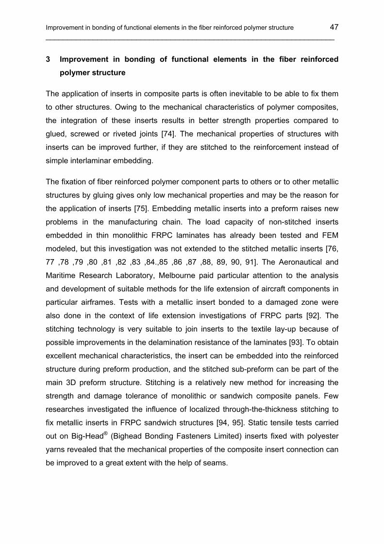
Improvement in bonding of functional elements in the fiber reinforced polymer structure 47 ___________________________________________________________________
3 Improvement in bonding of functional elements in the fiber reinforced polymer structure
The application of inserts in composite parts is often inevitable to be able to fix them
to other structures. Owing to the mechanical characteristics of polymer composites,
the integration of these inserts results in better strength properties compared to
glued, screwed or riveted joints [74]. The mechanical properties of structures with
inserts can be improved further, if they are stitched to the reinforcement instead of
simple interlaminar embedding.
The fixation of fiber reinforced polymer component parts to others or to other metallic
structures by gluing gives only low mechanical properties and may be the reason for
the application of inserts [75]. Embedding metallic inserts into a preform raises new
problems in the manufacturing chain. The load capacity of non-stitched inserts
embedded in thin monolithic FRPC laminates has already been tested and FEM
modeled, but this investigation was not extended to the stitched metallic inserts [76,
77 ,78 ,79 ,80 ,81 ,82 ,83 ,84.,85 ,86 ,87 ,88, 89, 90, 91]. The Aeronautical and
Maritime Research Laboratory, Melbourne paid particular attention to the analysis
and development of suitable methods for the life extension of aircraft components in
particular airframes. Tests with a metallic insert bonded to a damaged zone were
also done in the context of life extension investigations of FRPC parts [92]. The
stitching technology is very suitable to join inserts to the textile lay-up because of
possible improvements in the delamination resistance of the laminates [93]. To obtain
excellent mechanical characteristics, the insert can be embedded into the reinforced
structure during preform production, and the stitched sub-preform can be part of the
main 3D preform structure. Stitching is a relatively new method for increasing the
strength and damage tolerance of monolithic or sandwich composite panels. Few
researches investigated the influence of localized through-the-thickness stitching to
fix metallic inserts in FRPC sandwich structures [94, 95]. Static tensile tests carried
out on Big-Head® (Bighead Bonding Fasteners Limited) inserts fixed with polyester
yarns revealed that the mechanical properties of the composite insert connection can
be improved to a great extent with the help of seams.
48 ___________________________________________________________________
A polyester, twisted multifilament thread impregnates inadequately because of its
tight structure. On the other hand, core spun threads have a more open structure,
thus, they can be completely impregnated [96]. Therefore, during the experiments,
the behavior of the used stitching thread was also analyzed in terms of thread matrix
bonding, ultimate compatibility and contribution towards the strength. The finite
element (FE) analysis was applied to cross check the theoretical and actual failure
positions and modes of the bonded inserts.
3.1 Specimen development
As shown in Figure 3.1, Big-Head® inserts were applied as load carrying elements
which are later embedded in polymer composites. A steel insert consists of a
screwed bolt (M6) and a base metal plate (Ø38 mm) perforated in two circular rows
with 6 and 12 holes. The diameter of the holes at the inner and the outer pitch circle
is 4 mm and 5 mm, respectively, and the thickness of the base plate is 1.5 mm. The
application of this insert made it possible to optimize the design and to carry out
exact fracture mechanical experiments. Before embedding the metallic inserts were
treated (washed) in acetone for the good bonding between the insert base plate and
the resin of the composite.
Type A∅38 mm
Figure 3.1: Big-Head® insert (Type A)
In all cases, the metallic inserts were embedded in glass fiber reinforced epoxy
matrix composites. The matrix material used for RTM was a Rutepox VE 4908, a low
viscosity (120 ±20 mPas) resin (producer: Bakelite AG). The reinforcing structure
consisted of glass fiber non-crimp fabric of 894 g/m² specific weight and +45°/-
45°/+45° orientation (producer: Saertex GmbH & Co. KG). The inserts were fixed to
the fabric with and without stitching during the preform technology (Figure 3.2).
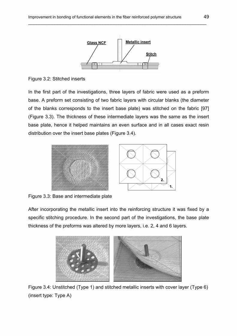
Improvement in bonding of functional elements in the fiber reinforced polymer structure 49 ___________________________________________________________________
Figure 3.2: Stitched inserts
In the first part of the investigations, three layers of fabric were used as a preform
base. A preform set consisting of two fabric layers with circular blanks (the diameter
of the blanks corresponds to the insert base plate) was stitched on the fabric [97]
(Figure 3.3). The thickness of these intermediate layers was the same as the insert
base plate, hence it helped maintains an even surface and in all cases exact resin
distribution over the insert base plates (Figure 3.4).
1.
2.
1.
2.
Figure 3.3: Base and intermediate plate
After incorporating the metallic insert into the reinforcing structure it was fixed by a
specific stitching procedure. In the second part of the investigations, the base plate
thickness of the preforms was altered by more layers, i.e. 2, 4 and 6 layers.
Figure 3.4: Unstitched (Type 1) and stitched metallic inserts with cover layer (Type 6)
(insert type: Type A)
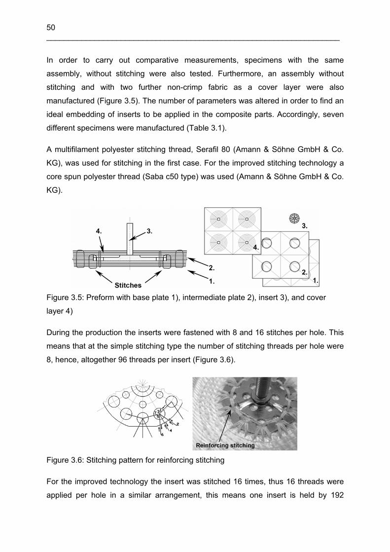
50 ___________________________________________________________________
In order to carry out comparative measurements, specimens with the same
assembly, without stitching were also tested. Furthermore, an assembly without
stitching and with two further non-crimp fabric as a cover layer were also
manufactured (Figure 3.5). The number of parameters was altered in order to find an
ideal embedding of inserts to be applied in the composite parts. Accordingly, seven
different specimens were manufactured (Table 3.1).
A multifilament polyester stitching thread, Serafil 80 (Amann & Söhne GmbH & Co.
KG), was used for stitching in the first case. For the improved stitching technology a
core spun polyester thread (Saba c50 type) was used (Amann & Söhne GmbH & Co.
KG).
Figure 3.5: Preform with base plate 1), intermediate plate 2), insert 3), and cover
layer 4)
During the production the inserts were fastened with 8 and 16 stitches per hole. This
means that at the simple stitching type the number of stitching threads per hole were
8, hence, altogether 96 threads per insert (Figure 3.6).
Figure 3.6: Stitching pattern for reinforcing stitching
For the improved technology the insert was stitched 16 times, thus 16 threads were
applied per hole in a similar arrangement, this means one insert is held by 192

Improvement in bonding of functional elements in the fiber reinforced polymer structure 51 ___________________________________________________________________
stitches. Furthermore, the stitch points were positioned 2 mm from the edge of the
insert base plate compared to the previous volume of 4 mm.
Table 3.1: Specimen selection
Type of specimens Stitches Without cover With cover
Specimen without stitching 0 X (Type 1) X (Type 5)
Single stitching with Serafil 80 type PET thread 96 X (Type 2) -
Improved stitching with Saba c50 type PET thread 192 X (Type 3) X (Type 6)Improved stitching with Saba c50 PET type thread, with 2, 4 ,6 base plates 192 X (Type 3) -
Improved double stitching with Saba c50 type PET thread 384 X (Type 4) -
Table 3.2: Specimen architectures
Improved stitching with cover layer (Type 6)
Single and improved stitching(Type 2, 3, 4, and Type 8, 9, 10)*
Specimen without stitching(Type 1)
Specimen without stitching, with cover layer (Type 5)
Insert without embeddingType 7
* = Embedded inserts, stitched with different threads:
- Type 2: PET, Amann Serafil 80- Type 3, 4: PET, Amann Saba c50- Type 8: Kevlar®, Amann Kevlar® No. 50- Type 9: Glass, Culimeta MN30- Type 10: Carbon, 1K IVW CF
thread (Tenax HTA 5641)
The advantage of this technology is the smaller angle of thread pull which results
from bonding of the insert with the base fabric. Again, the short span length of the

52 ___________________________________________________________________
thread (2 mm) at the load bearing area does not allow easy elastic deformation of a
thread at this specified stitch. This can help improve the tensile properties of the
stitched insert.
The Saba c50 (67.2 tex) thread applied in the improved technology can be more
easily wetted by the epoxy resin, and the adhesion between the resin and the thread
is stronger compared to Serafil 80 (36.6 tex) [55, 96] (Table 3.8). In case of the
double stitched inserts (using the improved technology) the double amount of
stitching thread was introduced into the assembly. This means that 384 stitches hold
the insert. Table 3.2 shows the type of the insert embedding and the specimen
architectures.
The applied thread tension was identical in all cases (FNT = 310 cN, FBT = 100 cN)
and hence modified lock stitches can be produced [98]. A semiautomatic stitching
machine, Pfaff 3574 (Pfaff Industriemaschinen AG), was used for the preform
production. During the stitching process the exact position of the inserts were fixed
by adjustable insert holders.
After the preform was placed in the RTM mold the vacuum assisted resin infusion
molding technique (VARI) was used for the specimen manufacturing. The screwed
bolt of the insert was placed into the silicon rubber cartridge, which protects the
screw from resin contaminations. All the VARI parameters, for instance, tool set-up,
vacuum, type of resin, applied curing time, temperature etc. were kept the same in all
cases (Table 3.3). The fiber volume content in the composite base plate was 50%.
Table 3.3: Parameters of the VARI process
Resin type Temperature of injection
Vacuum of injection
Cure temperature Cure time
Rutepox VE 4908 23 °C 5 mbar 80 °C 6 hour
3.2 Experiments and results
In order to compare different technologies used in the production, simple tensile tests
were carried out [99]. During the experiment the force needed for specimen fracture
was measured and the characteristic failure modes were observed. The specimens
with a 75 x 75 mm GF/EP composite base plate were clamped by a 55 x 55 mm
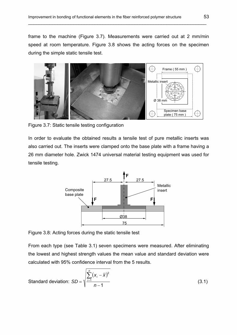
Improvement in bonding of functional elements in the fiber reinforced polymer structure 53 ___________________________________________________________________
frame to the machine (Figure 3.7). Measurements were carried out at 2 mm/min
speed at room temperature. Figure 3.8 shows the acting forces on the specimen
during the simple static tensile test.
Frame ( 55 mm )
Specimen base plate ( 75 mm )
Metallic insert
Ø 38 mm
Figure 3.7: Static tensile testing configuration
In order to evaluate the obtained results a tensile test of pure metallic inserts was
also carried out. The inserts were clamped onto the base plate with a frame having a
26 mm diameter hole. Zwick 1474 universal material testing equipment was used for
tensile testing.
F
F
F
27.5 27.5
Ø38
75
Compositebase plate
Metallic insert
Figure 3.8: Acting forces during the static tensile test
From each type (see Table 3.1) seven specimens were measured. After eliminating
the lowest and highest strength values the mean value and standard deviation were
calculated with 95% confidence interval from the 5 results.
Standard deviation: ( )
11
2
−
−=∑=
n
xxSD
n
ii
(3.1)
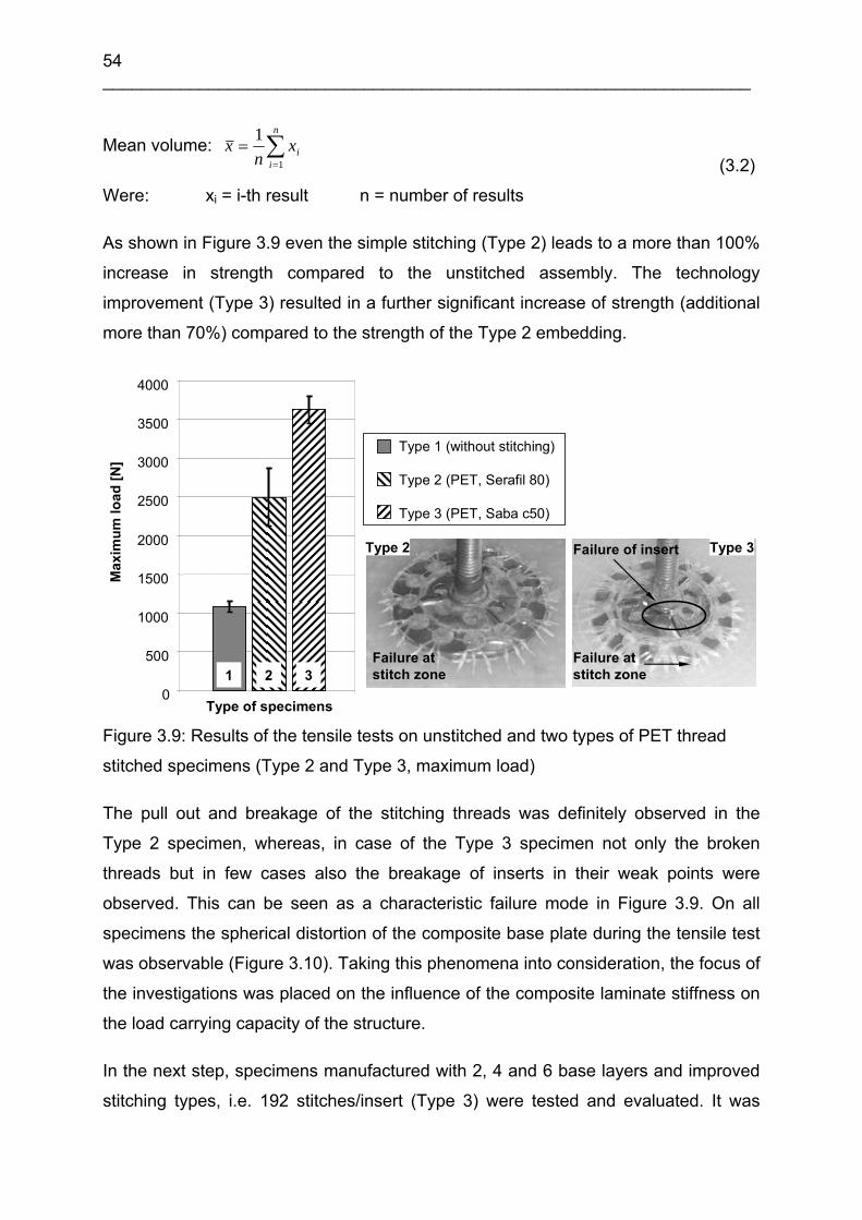
54 ___________________________________________________________________
Mean volume: xn
xii
n
==∑1
1 (3.2)
Were: xi = i-th result n = number of results
As shown in Figure 3.9 even the simple stitching (Type 2) leads to a more than 100%
increase in strength compared to the unstitched assembly. The technology
improvement (Type 3) resulted in a further significant increase of strength (additional
more than 70%) compared to the strength of the Type 2 embedding.
0
500
1000
1500
2000
2500
3000
3500
4000
Type of specimens
Max
imum
load
[N]
Type 1 (without stitching)
Type 2 (PET, Serafil 80)
Type 3 (PET, Saba c50)
Failure at stitch zone
Type 2 Failure of insert
Failure at stitch zone
Type 3
1 2 3
Figure 3.9: Results of the tensile tests on unstitched and two types of PET thread
stitched specimens (Type 2 and Type 3, maximum load)
The pull out and breakage of the stitching threads was definitely observed in the
Type 2 specimen, whereas, in case of the Type 3 specimen not only the broken
threads but in few cases also the breakage of inserts in their weak points were
observed. This can be seen as a characteristic failure mode in Figure 3.9. On all
specimens the spherical distortion of the composite base plate during the tensile test
was observable (Figure 3.10). Taking this phenomena into consideration, the focus of
the investigations was placed on the influence of the composite laminate stiffness on
the load carrying capacity of the structure.
In the next step, specimens manufactured with 2, 4 and 6 base layers and improved
stitching types, i.e. 192 stitches/insert (Type 3) were tested and evaluated. It was

Improvement in bonding of functional elements in the fiber reinforced polymer structure 55 ___________________________________________________________________
interesting to find that as the number of base layers increases the spherical distortion
of the specimen under the clamping frame reduces.
Side viewThe deformedspecimen baseplate
FSpecimen
Figure 3.10: The deformed specimen base plate during tensile test
It can be seen clearly in Figure 3.12 that the structure strength did not change
essentially, but the stiffness changed considerably. The visibility of first delaminations
of the insert is specimen dependent. In case of 2 base layers the first delamination
that appears always under the screwed bolt of the insert is not noticeable but in the
case of 4 and 6 layers it is revealed (Figure 3.11).
FPosition of the first delamination
Figure 3.11: Position of the first delamination in the structure
Specimens with 2 layers could follow the spherical distortion during the tensile test,
whereas, the specimen with 4 and 6 base layers do not show this phenomena.
Therefore, the first delamination appears at a relatively low force range and it is well
marked. The adhesive bonding between the metallic insert and the matrix material
broke, as well as the resin layer sheared above the insert base plate at this force
range. After this, the stitches take over the large proportion of load. The specimen
undergoes irreversible damage, nevertheless the seams increase the load carrying
capacity of the insert.

56 ___________________________________________________________________
0
500
1000
1500
2000
2500
3000
3500
4000
4500
5000
0 1 2 3 4 5 6 7 8
Displacement [mm]
Forc
e [N
]
2 layers4 layers
6 layers
Figure 3.12: Change of the specimen stiffness in case of different number of base
layers (Type of specimen: Type 3)
In case of specimen Type 4, where the inserts (Type A) were fixed with the improved
double stitching, only the insert failure was noticed. The smaller range of deviation
also reveals a homogenous failure mode. This implies that with this reinforcing
stitching the limit value of the inserts’ load carrying capacity was reached.
0
1000
2000
3000
4000
5000
Type of specimens
Max
imum
load
[N]
Type 1 (without stitching)
Type 3 (PET, Saba c50)
Type 4 (PET, Saba c50)
Failure of insert
Type 4
1 3 4
Figure 3.13: Results of the tensile tests and characteristic failure mode of the
specimen Type 4 (Maximum load)

Improvement in bonding of functional elements in the fiber reinforced polymer structure 57 ___________________________________________________________________
In this case, the stitches show almost no failure and the weak point of the system is
shifted to the metallic insert Figure 3.13. With this type of stitching (Type 4) fivefold
reinforcements can be achieved compared to the unstitched type (Type 1).
In case of specimen Type 5 the inserts were implemented without stitching but with a
cover layer (Figure 3.4). The force - displacement diagram shows the higher stiffness
of the specimen that arises from this construction (Figure 3.17, curve: Type 5). The
result of this specimen type was distinguishable in all cases and the delamination
between the cover and immediate layers could also be observed (Figure 3.14). This
specimen type demonstrated a good reinforcing effect, but only with the larger
standard deviation for strength values. The cover layer prevents the breakage of the
inserts due to a reduced load per unit area acting on the insert. This is the reason for
the further strength increase. This embedding type shows an improved performance
compared to the stitched insert systems but the exact positioning of inserts is very
difficult during the manufacturing process.
0
1000
2000
3000
4000
5000
6000
7000
Type of specimens
Type 1 (without stitching)
Type 5 (with cover layer)
Type 6 (PET, Saba c50 + cover layer)
Max
imum
load
[N]
DelaminationDelamination
Type 5
1 5 6
Figure 3.14: Results on the tensile tests of specimens with cover layer and the
characteristic failure mode of the specimen Type 5 (Maximum load)
In case of specimen Type 6 stitching and covering were carried out simultaneously
(Figure 3.5, Table 3.2) and a further significant increase in the delamination
resistance has been observed (Figure 3.14). In this case the cover layer made the

58 ___________________________________________________________________
insert failure mechanism more difficult and stitches prevented delamination (Figure
3.15). The range of standard deviation was much smaller than in the previous cases,
hence, the higher reliability of this embedding type is demonstrated. The insert failure
occurs at the inner pitch circle close to the bolt of the insert.
To cross check the above mentioned investigations, pure metallic inserts without
embedding (Type 7) were also tested. In this case a testing frame built with a Ø26
mm cavity in the center was used as an insert holder. The metallic inserts were fixed
with this holder frame to their base plates (Ø38 mm) during the tensile test. The
result shows that the maximum value of the insert load carrying capacity varies from
80 to 130% of the embedded inserts (Type 4 and Type 6). Figure 3.15 shows the
typical insert failure caused by tensile stress, and the resulting shear loading. During
the tensile test, the metallic insert without embedding shows higher strength than the
inserts stitched with the improved technology (Embedding types: Type 3 and Type 4).
This may be the reason of the flexible clamping of the inserts, because in this case
the base plate of the inserts is partially pulled out from the clamping frame. It has
been observed that the plastic deformation of the insert base plates increase the
breaking force of the metallic insert. The insert base plate was bell-shaped and,
therefore, it took up most of the tensile stress, while at the embedded types
transverse movement was arrested through the stitched base plate. Therefore, in the
embedded case the insert base plate takes up the majority of shear stress.
Failure of insert
Type 6
Type 7
Lamellabreakage
Figure 3.15: Fracture type of the embedded metallic insert (Type 6) and insert
without embedding (Type 7)
The Table 3.4 shows the summarised mean values of the measured maximum forces
and the standard deviations in case of the different specimens. Figure 3.17 shows
the characteristic force - displacement diagrams of the different specimens.

Improvement in bonding of functional elements in the fiber reinforced polymer structure 59 ___________________________________________________________________
Table 3.4: Test results
Type Type of specimen Stitches Mean F (N) SD
1 Without stitching 0 1084 67.3
2 Single stitching with Serafil 80 type PET thread 96 2496 373.5
3 Improved stitching with Saba c50 type PET thread 192 3628 175.9
4 Improved double stitching with Saba c50 type PET thread 384 4742 58.3
5 Without stitching, with cover layers 0 5155 242.1
6 Improved stitching with Saba c50 type PET thread and with cover layers 192 6022 101.1
7 Metallic insert 0 5203 280.5
Type of specimen0
1000
2000
3000
4000
5000
6000
7000
Type of the specimen
Max
imum
load
[N
]
1 2 543 6 7
Type of the specimen
1 2 543 6 7
Type of specimen Figure 3.16: Comparison of differently stitched specimens (Maximum load)
To the extent that the economic aspect of the technology is concerned, the
mechanical characterization of the metallic inserts can be improved by using stitching
technologies and preforming techniques. At the same time the high performing costs
must be considered as a disadvantage. Furthermore, manufacturing of different sub-
preforms and assembling them into the net shape structure needs more time and
manpower.

60 ___________________________________________________________________
0
1000
2000
3000
4000
5000
6000
7000
0.0 2.0 4.0 6.0 8.0
Displacement [mm]
Forc
e [N
]
Type 1
Type 2
Type 3
Type 4
Type 5Type 6
Type 7
Figure 3.17: Characteristic force - displacement diagrams of different specimens
3.3 Investigations with high performance fibers
The aim of the following examinations is to study the applicability of high
performance stitching threads in the fixing stitches of metallic inserts. Static tensile
tests carried out on inserts fixed with polyester threads revealed that stitching
improve the mechanical properties of the connection between the composite and the
insert to a great extent [100]. The investigations below involve the evaluation of the
mechanical investigations of metallic inserts stitched to the composite preform with
high performance threads.
The above mentioned Big-Head® inserts were fixed in the preform of the specimens
with high strength carbon, glass and aramid threads. The same stitching pattern and
the same glass NCF was used to build up the specimens as applied in case of the
investigation carried out on samples stitched with polyester fibers, hence the results
of these two experiments can be compared properly.
After the first investigations with a core spun polyester (PET) thread (Saba c50) and
Kevlar® spun thread (No. 50 7627 Amann & Söhne GmbH & Co. KG) a multifilament
glass fiber, Culimeta MN 30 (Culimeta Textilglas-Technologie GmbH & Co.KG), and

Improvement in bonding of functional elements in the fiber reinforced polymer structure 61 ___________________________________________________________________
1K CF fiber stitching thread (patented by the Institute für Verbundwerkstoffe GmbH)
were used for the following experiments.
Table 3.5 contains the specimen selection. All the RTM parameters for specimen
manufacturing, for instance, tool, vacuum, type of resin, applied curing time,
temperature etc. were kept the same in all cases (Table 3.3).
Table 3.5: Specimen selection
Type Type of specimen Stitches Without cover With cover
8 Improved stitching with Amann No. 50 type Kevlar® thread 192 X -
9 Improved stitching with Culimeta MN 30 type glass thread 192 X -
10 Simple stitching** with 1K CF thread (Tenax HTA 5641) 96 X -
** = Improved stitching with reduced stitch number
Table 3.6 shows the mechanical properties of the dry stitching threads (without resin)
applied for the investigations. The theoretical cross-section values are calculated
from the material density and the specific weight values of the threads.
Table 3.6: Data sheet of the applied stitching threads
Thread type Maximum
Force Fmax (N)
Specific weight
tex (g/1000m)
Densityρ
(g/cm3)
Theoretical cross- section A (mm2)
Elongation ε (%)
Theoreticalmaximal stress σ (MPa)
Amann Serafil 80 22 36.6 1.34 0.0273* 16 806* Amann Saba c50 31 67.2 1.34 0.0501* 19 620* Amann Kevlar® No. 50 76 61.5 1.44 0.0427* 4 1780* Culimeta MN30 64/128* 139 2.60 0.0534* 4.8 2400 1K IVW CF thread (Tenax HTA 5641) 143* 67 1.78 0.0376* 1.4 3800
* = calculated values
Based on the values shown in Table 3.6 the calculated theoretical total cross section
and the maximum load force of the stitching threads are represented in the Table 3.7.
The values show the theoretical maximum loadability of the stitched inserts in case of
the different embedding types.
The examination of simple and double stitched inserts revealed that the reinforcing
effect is not in direct proportion with the amount of fibers used. The reason for this
phenomenon is that the thread already stitched in is damaged by the needle

62 ___________________________________________________________________
penetrating it in the next step. Hence the thread can only fulfill its function partially.
The extent of this damage is of course more significant in case of multiple stitched
inserts.
Table 3.7: Theoretical total cross section and maximum force of the stitching threads
per insert
Type of specimen StitchesTheoretical total
thread cross- section A (mm2)
Theoretical maximum
thread Force Fmax (N)
Type 2 Single stitching with Amann Serafil 80 type PET thread 96 5.2416* 4224*
Type 3 Improved stitching with Amann Saba c50 type PET thread 192 19.2384* 11904*
Type 4 Improved double stitching with Amann Saba c50 type PET thread 384 38.4768* 23808*
Type 8 Improved stitching Amann Kevlar No. 50 type thread 192 16.3968* 29184*
Type 9 Improved stitching with Culimeta MN30 type glass thread 192 20.5056* 24576*
Type 10 Simple stitching** with 1K IVW CF thread (Tenax HTA 5641) 96 7.2192* 27456*
* = calculated values ** = improved stitching with reduced stitch number
In comparison with the measured results (Table 3.4) the theoretical values verify the
observations that the threats are very strong degrade during the stitching process.
3.3.1 Experiments and results
In order to compare the different assembly technologies, static tensile tests were
carried out on high performance threads stitched specimens. During the experiment
the force needed for specimen fracture was measured and the characteristic failure
modes were observed. All parameters of the tests were identical with the parameters
used in case of the polyester threads (see in chapter 3.1 and chapter 3.2).
Tensile tests on stitched inserts (Type A) with improved stitching (Type 3 and Type 4)
revealed that the characteristic failure mode of the system is not the breakage of
single stitching threads but the breakage of the metallic insert. Alone this event
occurred when double PET stitches were applied as reinforcements (Type 4) (Figure
3.13).
If Kevlar® fiber were applied as stitching thread, the characteristic failure mode was
also the breakage of inserts (Figure 3.19). Hence, the real load capacity of these
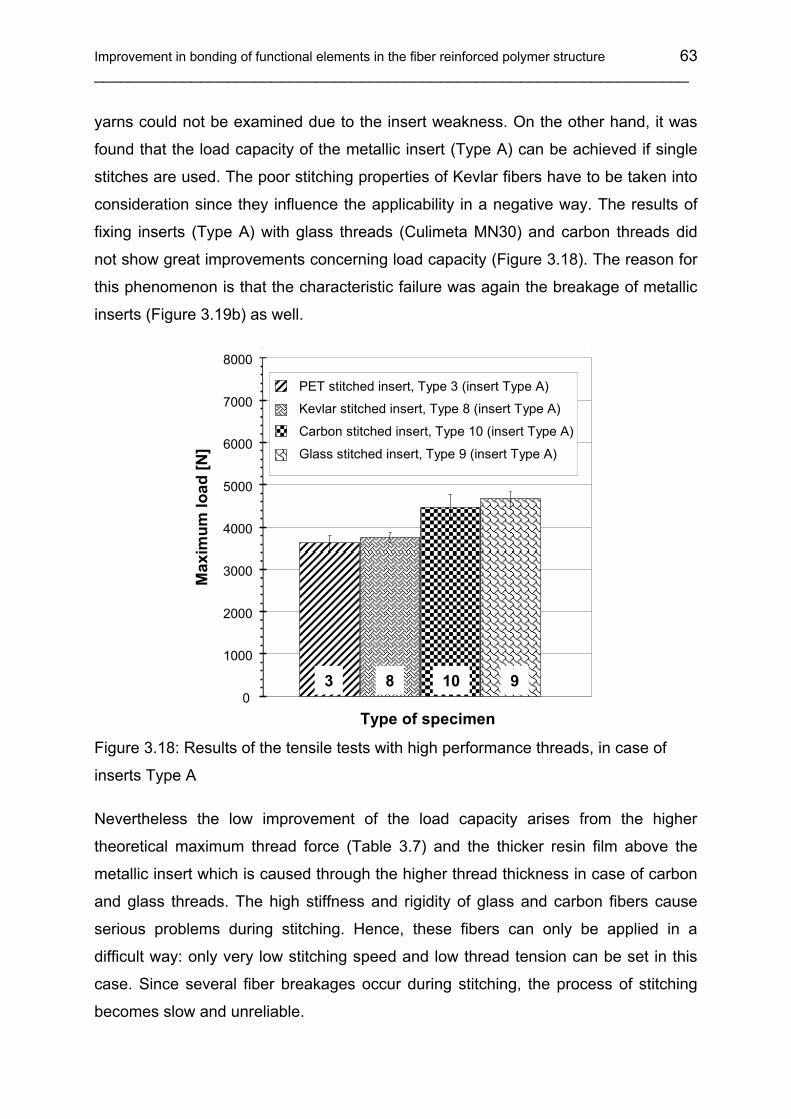
Improvement in bonding of functional elements in the fiber reinforced polymer structure 63 ___________________________________________________________________
yarns could not be examined due to the insert weakness. On the other hand, it was
found that the load capacity of the metallic insert (Type A) can be achieved if single
stitches are used. The poor stitching properties of Kevlar fibers have to be taken into
consideration since they influence the applicability in a negative way. The results of
fixing inserts (Type A) with glass threads (Culimeta MN30) and carbon threads did
not show great improvements concerning load capacity (Figure 3.18). The reason for
this phenomenon is that the characteristic failure was again the breakage of metallic
inserts (Figure 3.19b) as well.
0
1000
2000
3000
4000
5000
6000
7000
8000
Max
imum
load
[N] Glass stitched insert, Type 9 (insert Type A)
PET stitched insert, Type 3 (insert Type A)
Kevlar stitched insert, Type 8 (insert Type A)
Carbon stitched insert, Type 10 (insert Type A)
Type of specimen
3 8 10 9
Figure 3.18: Results of the tensile tests with high performance threads, in case of
inserts Type A
Nevertheless the low improvement of the load capacity arises from the higher
theoretical maximum thread force (Table 3.7) and the thicker resin film above the
metallic insert which is caused through the higher thread thickness in case of carbon
and glass threads. The high stiffness and rigidity of glass and carbon fibers cause
serious problems during stitching. Hence, these fibers can only be applied in a
difficult way: only very low stitching speed and low thread tension can be set in this
case. Since several fiber breakages occur during stitching, the process of stitching
becomes slow and unreliable.

64 ___________________________________________________________________
a)a)
Type 8
Type 10
Figure 3.19: Failure mode by reinforcing with a) Kevlar® thread and b) carbon thread
In case of insert Type A the mechanical properties of the PET Saba C50 thread
improved stitched reach the mechanical properties of the metallic inserts. Since
stitching with PET threads is easy and involves no problems, a higher stitching speed
can also be applied. The price of PET is lower than that of all the other investigated
fibers, hence, its application can be recommended when considering economical
aspects.
3.4 Specimen development
The real load capacity of fibers could not be measured due to the poor mechanical
characteristics of inserts Type A, though a need for an improved insert emerged. For
these investigations Big-Head® (Type A) inserts and inserts with improved base plate
geometry (Type B) were applied as load carrying elements. In order to be able to
compare the results exactly, only one geometrical parameter of the insert was
changed. The existing results show that the failure of metallic inserts occurred at the
base plate, and the weak point was the lamella between the inner pitch-circle holes.
A new, improved insert (Type B) with a thicker base plate was applied in the next
experiments (Figure 3.20). The improved steel insert (material: St 50-2 / S355J2G3,
Rm= 470-610 MPa, ReH = 295 MPa, A5= 20%) consists also of a screwed bolt (M6)
and a base metal plate perforated with two circular rows with 6 and 12 holes. The
diameter of the holes at the inner and the outer pitch-circle is 4 mm and 5 mm,
respectively and the thickness of the base plate in case of improved inserts (Type B)
is 3 mm (Figure 3.20).

Improvement in bonding of functional elements in the fiber reinforced polymer structure 65 ___________________________________________________________________
Type A∅38 mm
Type B∅38 mm
Figure 3.20: Metallic insert (Type A) and improved metallic insert (Type B)
PET stitched insert, Type A
0
1000
2000
3000
4000
5000
6000
7000
8000
9000
10000
0 1 2 3 4 5 6 7 8 9Displacement [mm]
Forc
e [N
]
PET stitched insert, Type A
0
1000
2000
3000
4000
5000
6000
7000
8000
9000
10000
0 1 2 3 4 5 6 7 8 9Displacement [mm]
Forc
e [N
]
PET stitched insert, Type B
0
1000
2000
3000
4000
5000
6000
7000
8000
9000
10000
0 1 2 3 4 5 6 7 8 9Displacement [mm]
Forc
e [N
]
PET stitched insert, Type B
0
1000
2000
3000
4000
5000
6000
7000
8000
9000
10000
0 1 2 3 4 5 6 7 8 9Displacement [mm]
Forc
e [N
]
Figure 3.21: Result of the tensile tests on the PET stitched (Type of specimen: Type
3) inserts (Type A and B)
This way the breakage of the base plate could be eliminated, hence, the real load
capacity of fibers could be studied and the results could be compared with the results
obtained from the experiments of inserts Type A.
Investigation on insert Type B proved that specimens produced with improved
polyester stitches show higher values than Type A inserts reinforced with the same
stitching. The reasons for these values are the larger adhesion surface from the

66 ___________________________________________________________________
higher insert base plate thickness and higher stiffness and strength of insert Type B.
The base plate of the improved inserts did not bend, it transferred the loading to the
fibers evenly, and hence they could express their impact commonly. As a result, it
could be observed that all specimens with insert Type B were loaded safely up to
4500 N (Figure 3.21). The first delamination always took place at higher values than
in case of inserts Type A (Figure 3.21).
In order to carry out comparative measurements, specimens of the same assembly
but without stitching and with two further fabric layers with insert Type B (Figure 3.4b)
were also manufactured.
Kevlar® stitched insert, Type B
0
1000
2000
3000
4000
5000
6000
7000
8000
9000
10000
0 1 2 3 4 5 6 7 8 9Displacement [mm]
Forc
e [F
]
Kevlar® stitched insert, Type B
0
Kevlar® stitched insert, Type B
0
1000
2000
3000
4000
5000
6000
7000
8000
9000
10000
0 1 2 3 4 5 6 7 8 9Displacement [mm]
Forc
e [F
]
Figure 3.22: Result of the tensile tests on Kevlar® stitched (Type of specimen: Type
8) inserts (Type B)
The specimens produced with Kevlar® stitching threads show higher maximum
values than inserts stitched with polyester fibers. However the first breakage however
occurres at approx. 4500 N, then the specimens could be loaded reliably up to 6500

Improvement in bonding of functional elements in the fiber reinforced polymer structure 67 ___________________________________________________________________
N (Figure 3.22). This fact reveals that the first delamination under the screwed bolt
evolves at approx. 4500 N. The measured values show that the quality of thread
does not have an impact on this phenomenon; primarily the stiffness of the insert
influences this value.
Examinations of inserts produced with double stitches of polyester threads revealed
that the higher quantity of fibers result in higher load capacity, but this increase is not
linear. In average it provides 8000 N tensile force, while the single stitch results in a
load capacity of approx. 6200 N (Figure 3.23). The reason for this phenomenon is
that the thread already stitched in is damaged by the needle penetrating it in the next
step. Hence the thread can only fulfill its function partially. This damage is more
significant in case of multiple stitched inserts.
0
1000
2000
3000
4000
5000
6000
7000
8000
9000
10000
Type of specimen
Max
imum
load
[N]
PET stitched insert, Type 3 (insert Type B)
PET double stitched insert, Type 4 (insert Type B)3 4
Figure 3.23: Results of the tensile tests with PET threads (Type of specimen: Type 3
and Type 4), in case of insert Type B
3.5 Cyclic tensile test of insert Type B
In case of double stitched (Type 4) Type B inserts, the first delamination breakage
occurred only in the range above ca. 6000 N and the reason for it is the high stiffness
of the insert base plate. However, a smaller crack could be observed before the first
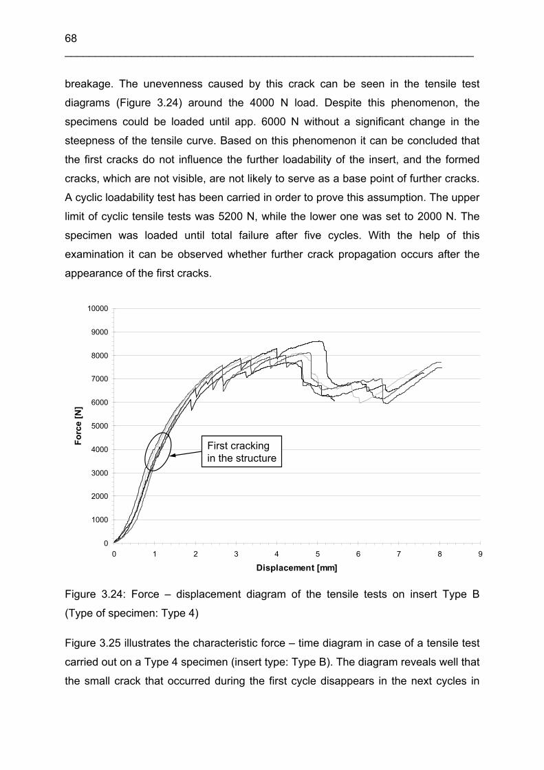
68 ___________________________________________________________________
breakage. The unevenness caused by this crack can be seen in the tensile test
diagrams (Figure 3.24) around the 4000 N load. Despite this phenomenon, the
specimens could be loaded until app. 6000 N without a significant change in the
steepness of the tensile curve. Based on this phenomenon it can be concluded that
the first cracks do not influence the further loadability of the insert, and the formed
cracks, which are not visible, are not likely to serve as a base point of further cracks.
A cyclic loadability test has been carried in order to prove this assumption. The upper
limit of cyclic tensile tests was 5200 N, while the lower one was set to 2000 N. The
specimen was loaded until total failure after five cycles. With the help of this
examination it can be observed whether further crack propagation occurs after the
appearance of the first cracks.
0
1000
2000
3000
4000
5000
6000
7000
8000
9000
10000
0 1 2 3 4 5 6 7 8 9
Displacement [mm]
Forc
e [N
]
First crackingin the structure
Figure 3.24: Force – displacement diagram of the tensile tests on insert Type B
(Type of specimen: Type 4)
Figure 3.25 illustrates the characteristic force – time diagram in case of a tensile test
carried out on a Type 4 specimen (insert type: Type B). The diagram reveals well that
the small crack that occurred during the first cycle disappears in the next cycles in

Improvement in bonding of functional elements in the fiber reinforced polymer structure 69 ___________________________________________________________________
the range between 2000 and 5200 N. Furthermore, the part of the curve after the
maximal load shows that the multiple loads in that range do not influence the
mechanical properties. The maximal force measured in the cyclic test is almost the
same as the value experienced in simple tensile tests (app. 8000 N). The first
delamination breakage occurred at the value of 6000 N in both cases.
The measurements revealed that the first hair-line cracks during the tensile test are
probably caused by the stress formed during the production of the matrix. However,
the occurrence of these hair-line cracks has in this case no significant influence on
the mechanical characteristics of the insert – composite contact.
0
1000
2000
3000
4000
5000
6000
7000
8000
9000
0 50 100 150 200 250 300 350 400 450
Time [s]
Forc
e [N
]
First crackingin the structure
Figure 3.25: Cyclic tensile diagram of the stitched insert Type B (Type of specimen:
Type 4)
3.6 Tensile tests of inserts fixed on the inner pitch circle
Since the first delamination breakage always occurs under the screwed bolt, the
examinations were extended to an insert variation where the inner pitch-circle was
also fixed (Figure 3.26, embedding type: Type 11). In this case the stitching threads
next to the screwed bolt eliminate or delay the first delamination. Since the fibers are
placed much closer to the place of the first delamination, their reinforcing impact is
more effective.
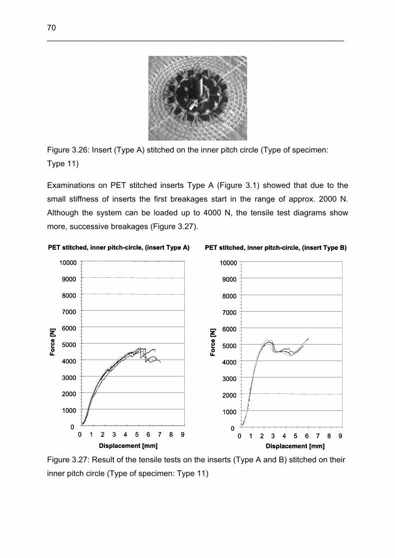
70 ___________________________________________________________________
Figure 3.26: Insert (Type A) stitched on the inner pitch circle (Type of specimen:
Type 11)
Examinations on PET stitched inserts Type A (Figure 3.1) showed that due to the
small stiffness of inserts the first breakages start in the range of approx. 2000 N.
Although the system can be loaded up to 4000 N, the tensile test diagrams show
more, successive breakages (Figure 3.27).
PET stitched, inner pitch-circle, (insert Type A)
0
1000
2000
3000
4000
5000
6000
7000
8000
9000
10000
0 1 2 3 4 5 6 7 8 9
Displacement [mm]
Forc
e [N
]
PET stitched, inner pitch-circle, (insert Type A)
0
1000
2000
3000
4000
5000
6000
7000
8000
9000
10000
0 1 2 3 4 5 6 7 8 9
Displacement [mm]
Forc
e [N
]
PET stitched, inner pitch-circle, (insert Type B)
0
1000
2000
3000
4000
5000
6000
7000
8000
9000
10000
0 1 2 3 4 5 6 7 8 9Displacement [mm]
Forc
e [N
]
PET stitched, inner pitch-circle, (insert Type B)
0
1000
2000
3000
4000
5000
6000
7000
8000
9000
10000
0 1 2 3 4 5 6 7 8 9Displacement [mm]
Forc
e [N
]
Figure 3.27: Result of the tensile tests on the inserts (Type A and B) stitched on their
inner pitch circle (Type of specimen: Type 11)

Improvement in bonding of functional elements in the fiber reinforced polymer structure 71 ___________________________________________________________________
It can be concluded that reinforcing inserts Type A on the inner pitch circle does
obviously cause positive changes on the load capacity of the construction (Figure
3.21 and Figure 3.27). In case of insert Type B, it can be seen, that the stitching on
the inner pitch circle causes no positive changes on the load capacity of the
construction.
When examining inserts Type B, it was found that stitching the inner pitch circle
prevented the occurrence of the first delamination that is expected at load values of
4500 N. The tensile test diagrams (Figure 3.27) showed that there is no breakage at
these values, but at 5200 N a significant drop is revealed referring to the breakage of
the stitches at the outer edge of the inserts.
The inserts do not delaminate from the base plate under the screwed bolts. Since the
insert is very stiff and cannot bend with the base plate, high stress evolves at the
edges of the insert plates. As a consequence, the ultimate breakage occurs within a
relatively small range after the first fiber breakage. The results reveal that in case of
insert Type B the first delamination can be hindered by reinforcing the inner pitch
circle with stitches, but this reinforcing mode did not increase the load capacity of the
system (Figure 3.21, type of specimen: Type 3, insert type: Type B).
3.7 Finite element modeling of tensile tests
Nowadays the numerical methods widespread in engineering shorten the design
process significantly. With their help, the strength and other parameters of the parts
can already be examined and hence optimized according to the requirements in the
design phase. In case of mechanical calculations, the most widespread numerical
method is finite element modeling (FEM), a node oriented process. This can also be
considered as the classical Ritz method with a special property that the base
functions for discretization use the principle of local approach [101]. This principle
provides the solution in nodes (discretized points) among which the displacement
field can be interpolated with the help of the form functions. The simple, linearly
elastic FEM calculations can be described by the known equation of K U = f (where K
is the sum of the stiffness matrix of the elements, U is the generalized node
displacement, f is the typical right side vector and the external loading is presented in
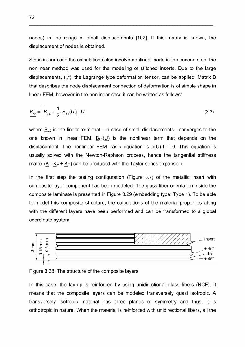
72 ___________________________________________________________________
nodes) in the range of small displacements [102]. If this matrix is known, the
displacement of nodes is obtained.
Since in our case the calculations also involve nonlinear parts in the second step, the
nonlinear method was used for the modeling of stitched inserts. Due to the large
displacements, (εL), the Lagrange type deformation tensor, can be applied. Matrix B
that describes the node displacement connection of deformation is of simple shape in
linear FEM, however in the nonlinear case it can be written as follows:
UUBBKLLG ⋅⎥⎦
⎤⎢⎣⎡ ⋅+= )(
21
10 (3.3)
where BL0 is the linear term that - in case of small displacements - converges to the
one known in linear FEM. BL1(U) is the nonlinear term that depends on the
displacement. The nonlinear FEM basic equation is p(U)-f = 0. This equation is
usually solved with the Newton-Raphson process, hence the tangential stiffness
matrix (K= KM + KG) can be produced with the Taylor series expansion.
In the first step the testing configuration (Figure 3.7) of the metallic insert with
composite layer component has been modeled. The glass fiber orientation inside the
composite laminate is presented in Figure 3.29 (embedding type: Type 1). To be able
to model this composite structure, the calculations of the material properties along
with the different layers have been performed and can be transformed to a global
coordinate system.
3 m
m
0,15
mm
0,3
mm
3 m
m
0.15
mm
0.3
mm
3 m
m
0,15
mm
0,3
mm
3 m
m
0.15
mm
0.3
mm Insert
+ 45°- 45°+ 45°
Figure 3.28: The structure of the composite layers
In this case, the lay-up is reinforced by using unidirectional glass fibers (NCF). It
means that the composite layers can be modeled transversely quasi isotropic. A
transversely isotropic material has three planes of symmetry and thus, it is
orthotropic in nature. When the material is reinforced with unidirectional fibers, all the

Improvement in bonding of functional elements in the fiber reinforced polymer structure 73 ___________________________________________________________________
fibers are aligned in direction p. In this case the in plane material properties
perpendicular to the fibers (q-r plane) are modeled isotropic, due to a homogeneous
fiber distribution in this cross section (Figure 3.29) [103].
p
r
q
Plane of isotropy
p
r
q
Plane of isotropy Figure 3.29: The fiber orientation of the composite layers (transversely isotropic
composite material)
The stress strain relationship in the primed coordinate system written by the
transformation matrices is shown in equation (3.4) and (3.5).
[ ][ ]
32144 344 21321''
1
' ε
εεσ
σ
σεσ ⎥⎦⎤
⎢⎣⎡
⎥⎦⎤
⎢⎣⎡
⎥⎦⎤
⎢⎣⎡=⎥⎦
⎤⎢⎣⎡
−
TTCTT
C
(3.4)
[ ] ''' εσ C= (3.5)
Where:
σ is the stress matrix in the coordinate system of the fibers
⎥⎦⎤
⎢⎣⎡
σT is the three dimensional stress transformation matrix
'σ is the stress matrix transformed into the primed coordinate system
ε is the strain matrix in the coordinate system of the fibers
⎥⎦⎤
⎢⎣⎡
εT is the three dimensional strain transformation matrix
'ε is the strain matrix transformed into the primed coordinate system

74 ___________________________________________________________________
[ ]C is the stiffness matrix in the coordinate system of the fibers
[ ]'C is the stiffness matrix transformed into the primed coordinate system
The transformed stiffness matrix is written by the three dimensional stress and strain
transformation matrices (equation 3.6) [103].
[ ] [ ]1
'−
⎥⎦⎤
⎢⎣⎡
⎥⎦⎤
⎢⎣⎡=
εσTCTC (3.6)
With the actual material data (Ep= 40 GPa, Eq= 6 GPa, Gpq= 3.75 GPa, νpq= 0.27,
νqr= 0.4) and using the equations (3.4), (3.6) the stiffness matrices for both layers
with +45° and -45° fiber orientation can be calculated. The calculation results show
the (3.7) and (3.8) matrices.
[ ] [ ]GPaC
⎥⎥⎥⎥⎥⎥⎥⎥
⎦
⎤
⎢⎢⎢⎢⎢⎢⎢⎢
⎣
⎡
−−−
−
−−
=°+
81.1000122.0545.8545.80946.2803.00000803.0946.2000122.000332.7924.2924.2545.800924.2362.17862.9545.800924.2862.9362.17
' 45 (3.7)
[ ] [ ]GPaC
⎥⎥⎥⎥⎥⎥⎥⎥
⎦
⎤
⎢⎢⎢⎢⎢⎢⎢⎢
⎣
⎡
−
−=°−
81.1000122.0545.8545.80946.2803.00000803.0946.2000122.000332.7924.2924.2
545.800924.2362.17862.9545.800924.2862.9362.17
' 45 (3.8)
3.7.1 Finite element analysis
The target of the FE investigations in the first stage is to study the modeling methods
of a layered composite structure with embedded metallic insert. The first section of
the inserts loading before of the failure of the structure was modeled by FE. The
characteristic failure mode after this section is delamination between the metallic
insert and the composite structure. The delamination was observed as a
characteristic failure mode in case of embedding type Type 1. A 3D FE model has
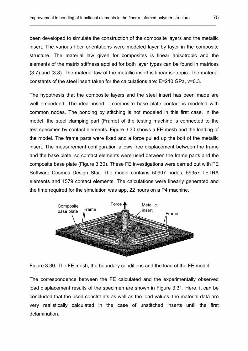
Improvement in bonding of functional elements in the fiber reinforced polymer structure 75 ___________________________________________________________________
been developed to simulate the construction of the composite layers and the metallic
insert. The various fiber orientations were modeled layer by layer in the composite
structure. The material law given for composites is linear anisotropic and the
elements of the matrix stiffness applied for both layer types can be found in matrices
(3.7) and (3.8). The material law of the metallic insert is linear isotropic. The material
constants of the steel insert taken for the calculations are: E=210 GPa, ν=0.3.
The hypothesis that the composite layers and the steel insert has been made are
well embedded. The ideal insert – composite base plate contact is modeled with
common nodes. The bonding by stitching is not modeled in this first case. In the
model, the steel clamping part (Frame) of the testing machine is connected to the
test specimen by contact elements. Figure 3.30 shows a FE mesh and the loading of
the model. The frame parts were fixed and a force pulled up the bolt of the metallic
insert. The measurement configuration allows free displacement between the frame
and the base plate, so contact elements were used between the frame parts and the
composite base plate (Figure 3.30). These FE investigations were carried out with FE
Software Cosmos Design Star. The model contains 50907 nodes, 59357 TETRA
elements and 1579 contact elements. The calculations were linearly generated and
the time required for the simulation was app. 22 hours on a P4 machine.
Force Metallic insert
FrameFrame
Composite base plate
Figure 3.30: The FE mesh, the boundary conditions and the load of the FE model
The correspondence between the FE calculated and the experimentally observed
load displacement results of the specimen are shown in Figure 3.31. Here, it can be
concluded that the used constraints as well as the load values, the material data are
very realistically calculated in the case of unstitched inserts until the first
delamination.
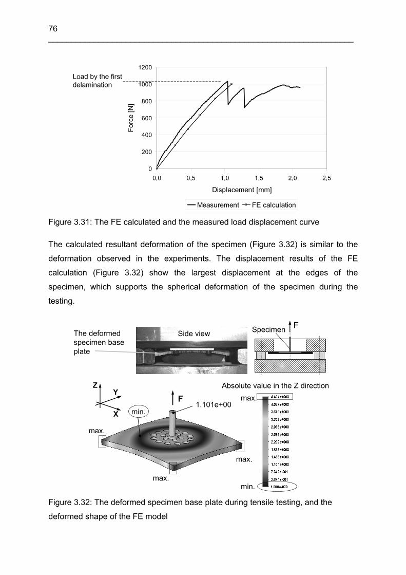
76 ___________________________________________________________________
0
200
400
600
800
1000
1200
0,0 0,5 1,0 1,5 2,0 2,5
Displacement [mm]
Forc
e [N
]
Measurement FE calculation
Load by the first delamination
Figure 3.31: The FE calculated and the measured load displacement curve
The calculated resultant deformation of the specimen (Figure 3.32) is similar to the
deformation observed in the experiments. The displacement results of the FE
calculation (Figure 3.32) show the largest displacement at the edges of the
specimen, which supports the spherical deformation of the specimen during the
testing.
Side viewThe deformedspecimen baseplate
FSpecimen
1.101e+00
max.
max.
max.
max.
min.
min.
ZY
X
Absolute value in the Z direction
F
Figure 3.32: The deformed specimen base plate during tensile testing, and the
deformed shape of the FE model

Improvement in bonding of functional elements in the fiber reinforced polymer structure 77 ___________________________________________________________________
The resultant displacement values are the absolute values of displacements effected
by the loading.
In Figure 3.33, the Von Mises stress result shows that the maximal stress will be
evaluated at weakest points of the steel insert. The experimental results shows, the
failure of the insert base plate is observed exactly at the calculated highest Von
Mises stress. In the composite laminates the evaluated Von Mises stress results are
lower than the stress in the steel insert, because of the lower values of the laminate
material properties. At this stress level no failure are observed in the composite
material.
Figure 3.34 shows the calculated equivalent strain results where the failure initiation
location at the maximum equivalent strain can be observed. In the composite
laminates the evaluated equivalent strain results are in the same range as in the
steel insert (Figure 3.15, Type 7).
Figure 3.33: The Von Mises stress FE calculation results by 1000 N load on the
insert and for the layers
The steel insert cannot be deformed as an ideal sphere segment because of the thick
neck of the thread on the base plate. So the delamination process between the steel
insert and the laminates will be evaluated under the thread at the backside of the
insert. The holes around the neck are stress expanding places.
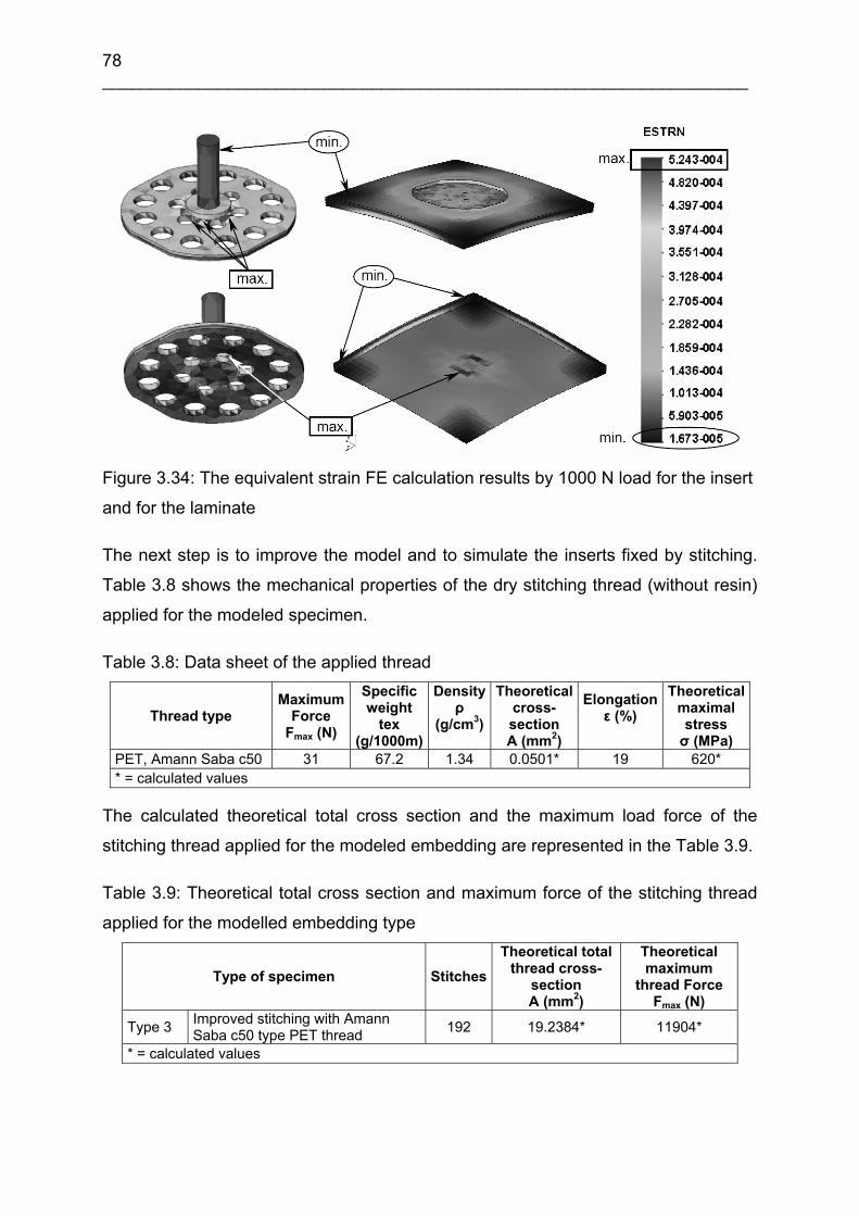
78 ___________________________________________________________________
Figure 3.34: The equivalent strain FE calculation results by 1000 N load for the insert
and for the laminate
The next step is to improve the model and to simulate the inserts fixed by stitching.
Table 3.8 shows the mechanical properties of the dry stitching thread (without resin)
applied for the modeled specimen.
Table 3.8: Data sheet of the applied thread
Thread type Maximum
Force Fmax (N)
Specific weight
tex (g/1000m)
Densityρ
(g/cm3)
Theoretical cross- section A (mm2)
Elongation ε (%)
Theoreticalmaximal stress σ (MPa)
PET, Amann Saba c50 31 67.2 1.34 0.0501* 19 620* * = calculated values
The calculated theoretical total cross section and the maximum load force of the
stitching thread applied for the modeled embedding are represented in the Table 3.9.
Table 3.9: Theoretical total cross section and maximum force of the stitching thread
applied for the modelled embedding type
Type of specimen StitchesTheoretical total
thread cross- section A (mm2)
Theoretical maximum
thread Force Fmax (N)
Type 3 Improved stitching with Amann Saba c50 type PET thread 192 19.2384* 11904*
* = calculated values

Improvement in bonding of functional elements in the fiber reinforced polymer structure 79 ___________________________________________________________________
The simulations were carried out with the ANSYS 10.0 software (supplier: ANSYS,
Inc.). The material constants used in the calculations are included in Table 3.10. The
embedding type of the simulated specimen is Type 3 (insert Type B).
Table 3.10: Applied material constatnts
Components MaterialsE
[GPa] G
[GPa] ν [-]
Rm [MPa]
εmax [%]
Insert Steel 210 0.3 300 (ReH) 3.2 Stitching yarn PET 7.5 620 19 Matrix Epoxy 3.4 1.2 0.35 64 1.9 Reinforcing material E-glass 80 37 0.18 3200 4.0
Where:
E Young’s modulus G Shear modulus ν Poisson’s ratio Rm Ultimate tensile strength ReH Yielding strength εmax Ultimate elongation
Since the task is to model a complex system, the different elements were defined
with different material laws. In case of stitched inserts, the primary load bearing
element is the stitching thread. The connection between the insert and the matrix
material formed during the injection can also be defined as a load bearing element.
The modeling task can be divided into three parts accordingly:
• Modelling the composite plate and the metallic insert • Modelling the insert bonding (reinforcing) stitching • As well as modelling the bonding effect of the matrix material on the
insert
The applied material laws for the participating elements:
• Insert linear elastic – ideal plastic, isotropic • Stitching yarn linear elastic, isotropic • Matrix linear elastic, isotropic • S-glass linear elastic, isotropic • Insert-matrix bonding special sigma-epsylon characteristic defined
Three different element types were used to model the different parts of the stitched
insert-composite base plate structure (Table 3.11). For the calculations in the model,
the orthotropic material properties of the composite base plate were defined with the
help of the correspondent real constants of the FE software.

80 ___________________________________________________________________
Table 3.11: Element types for the FE modeling using the definitions of ANSYS 10.0 Components Element type Element description Node Number of
elements
Stitching yarn LINK10
LINK10 is a 3-D spar element having the unique feature of a bilinear stiffness matrix resulting in a uniaxial tension-only (or compression-only) element.
2 180
Metallic insert SOLID95 20 5760 Insert-matrix bonding SOLID95 20 1520
Composite plate (orthotropic) SOLID95
SOLID95 is used for the 3-D modeling of solid structures. The element is defined by 20 nodes having three degrees of freedom per node
20 350
In order to be able to model the insert – matrix adhesion (Figure 3.36 b), an
intermediate layer between the composite base plate and the insert has to be defined
(insert-matrix bonding). The material law of this layer is defined with a given sigma-
epsilon curve that provided the good approximation of the effect of real adhesion in
the model. The maximum value of the tensile stress in the insert-matrix bonding is
set to 17.5 MPa and the maximum elongation is set to 2.9% [75]. According to the
material law, this intermediate layer can only reach a definite stress value, after
which the stress arising in the material will remain constant, i.e. the sigma-epsilon
curve will continue in a horizontal line (Figure 3.35). This way after reaching the
yielding stress in the insert-matrix bonding, the whole load of the insert will be
transferred through the stitching threads to the composite base plate. This behavior
corresponds to the already examined characteristic failure modes approximately. The
inserts delaminated from the composite plate under the threaded pin after a given
load value, and then the load was only taken by the stitching threads.
σ
ε
σ
ε
17.5 MPa
Figure 3.35: The defined material law of the insert-matrix bonding
The four different parts of the whole model are illustrated in Figure 3.36. Figure 3.37
shows the exact position of the modeled stitching threads in the structure. The

Improvement in bonding of functional elements in the fiber reinforced polymer structure 81 ___________________________________________________________________
threads are modeled with eight linear elastic, isotropic, LINK10 elements coupled to
the single insert holes. There through 64 elements hold the insert to the modeled
composite plate. Because the calculated total cross section of the stitching threads
are 19.2384 mm2 per insert (Table 3.9) to a first approximation the single thread
element cross sections were set to 0.3006 mm2 in the model.
a)
d)c)
b)a)
d)c)
b)
Figure 3.36: Parts for the whole model: a) insert, b) insert-matrix bonding, c)
composite base plate, d) the whole model with the stitching yarns
The parametric structure of the model makes it possible to choose the strength
properties of single parts, and this way the model can be adapted to the real values.
Due to the nonlinear element of the model, the simulation can approach the curves
that belong to real behavior of the structure well, even in case of stitched inserts.
Figure 3.37: Stitching threads in the FE model
After the set of the mechanical properties of the single modeled parts to the real
values (Table 3.10), the stitching thread cross section was changed to approach the

82 ___________________________________________________________________
measured curve characteristic of the static tensile test carried out on the specimen
Type 3 (insert Type B). The model was in this manner optimized.
The force-displacement curve shows that the simulation corresponds well to the
measurement results of an improved PET stitched, Type B insert (Figure 3.38).
0
1000
2000
3000
4000
5000
6000
7000
0,0 1,0 2,0 3,0 4,0 5,0
Displacement [mm]
Forc
e [N
]
Numerical simulationStatic tensile test
Figure 3.38: Result of the numerical simulation in case of stitched insert Type B
(Type of specimen: Type 3) compared with the measured values
Arrived the adequate curve characteristic the resultant cross section of the modeled
single stitching threads was 0,2147 mm2, thus the total resultant cross section of the
threads is 13.74 mm2. In comparison to the calculated theoretical total cross section
(19.2384 mm2) the values indicate the above-mentioned stitching thread degradation
during the stitching process.
Furthermore, the result of load simulation reveals the reasons for the characteristic
failure modes experienced in the measurements. In case of Type A inserts the first
breakage was always the delamination below the screwed bolt of the insert (Figure
3.11). The reason for this phenomenon is the different stiffness of the insert base
plate and the composite sheet. If the stiffness of the composite plate is higher than
that of the insert base plate, then large stresses may evolve in the zone below the
threaded pin during the bell-shaped deformation of the insert base plate, and as a
result the metal separates from the composite plate. This phenomenon is described
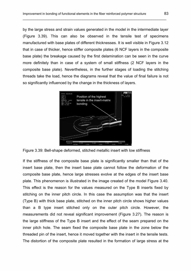
Improvement in bonding of functional elements in the fiber reinforced polymer structure 83 ___________________________________________________________________
by the large stress and strain values generated in the model in the intermediate layer
(Figure 3.39). This can also be observed in the tensile test of specimens
manufactured with base plates of different thicknesses. It is well visible in Figure 3.12
that in case of thicker, hence stiffer composite plates (6 NCF layers in the composite
base plate) the breakage caused by the first delamination can be seen in the curve
more definitely than in case of a system of small stiffness (2 NCF layers in the
composite base plate). Nevertheless, in the further stages of loading the stitching
threads take the load, hence the diagrams reveal that the value of final failure is not
so significantly influenced by the change in the thickness of layers.
Position of the highest tensile in the insert-matrix bonding
Figure 3.39: Bell-shape deformed, stitched metallic insert with low stiffness
If the stiffness of the composite base plate is significantly smaller than that of the
insert base plate, then the insert base plate cannot follow the deformation of the
composite base plate, hence large stresses evolve at the edges of the insert base
plate. This phenomenon is illustrated in the image created of the model Figure 3.40.
This effect is the reason for the values measured on the Type B inserts fixed by
stitching on the inner pitch circle. In this case the assumption was that the insert
(Type B) with thick base plate, stitched on the inner pitch circle shows higher values
than a B type insert stitched only on the outer pitch circle. However, the
measurements did not reveal significant improvement (Figure 3.27). The reason is
the large stiffness of the Type B insert and the effect of the seam prepared on the
inner pitch hole. The seam fixed the composite base plate in the zone below the
threaded pin of the insert, hence it moved together with the insert in the tensile tests.
The distortion of the composite plate resulted in the formation of large stress at the
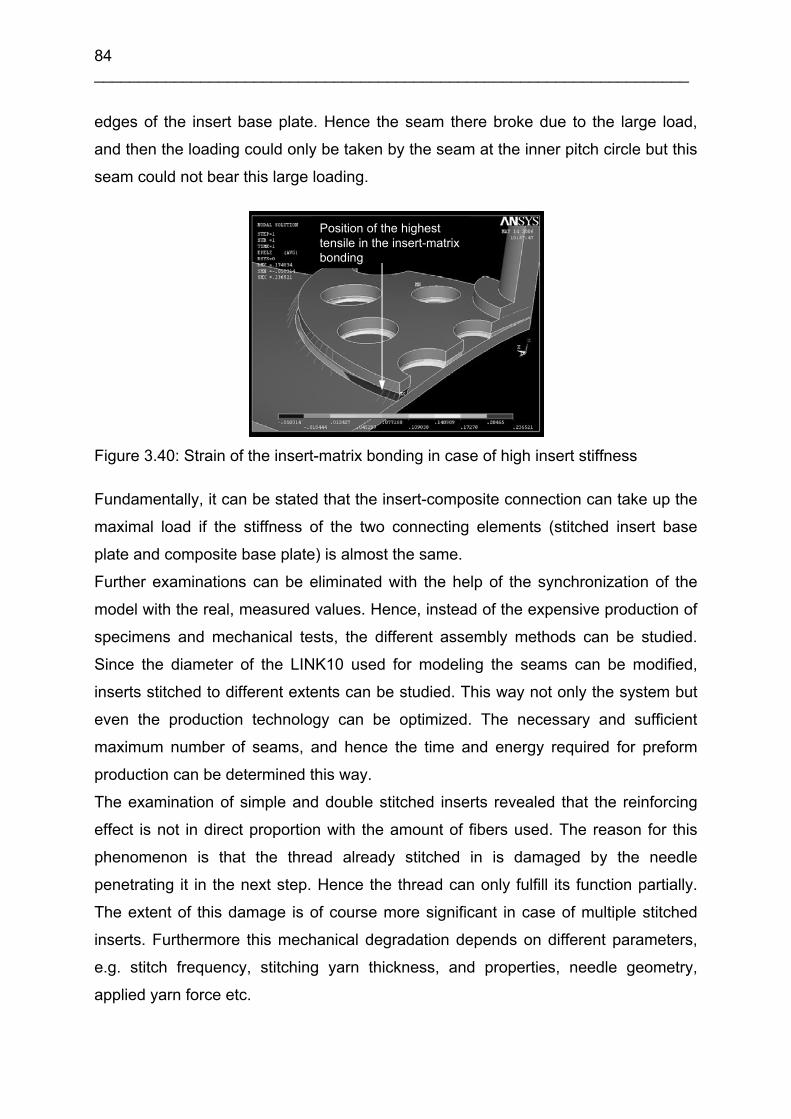
84 ___________________________________________________________________
edges of the insert base plate. Hence the seam there broke due to the large load,
and then the loading could only be taken by the seam at the inner pitch circle but this
seam could not bear this large loading.
Position of the highest tensile in the insert-matrix bonding
Figure 3.40: Strain of the insert-matrix bonding in case of high insert stiffness
Fundamentally, it can be stated that the insert-composite connection can take up the
maximal load if the stiffness of the two connecting elements (stitched insert base
plate and composite base plate) is almost the same.
Further examinations can be eliminated with the help of the synchronization of the
model with the real, measured values. Hence, instead of the expensive production of
specimens and mechanical tests, the different assembly methods can be studied.
Since the diameter of the LINK10 used for modeling the seams can be modified,
inserts stitched to different extents can be studied. This way not only the system but
even the production technology can be optimized. The necessary and sufficient
maximum number of seams, and hence the time and energy required for preform
production can be determined this way.
The examination of simple and double stitched inserts revealed that the reinforcing
effect is not in direct proportion with the amount of fibers used. The reason for this
phenomenon is that the thread already stitched in is damaged by the needle
penetrating it in the next step. Hence the thread can only fulfill its function partially.
The extent of this damage is of course more significant in case of multiple stitched
inserts. Furthermore this mechanical degradation depends on different parameters,
e.g. stitch frequency, stitching yarn thickness, and properties, needle geometry,
applied yarn force etc.

Improvement in bonding of functional elements in the fiber reinforced polymer structure 85 ___________________________________________________________________
The simulations make the thorough investigation of inserts fixed by stitching possible.
This way the characteristics of the connection between the insert and the composite
base plate can be revealed at a given load level. The stresses that evolve in the
insert and the base plate can be studied, the places of stress peaks can be found,
and hence an optimized geometry can be created. The aim of optimization is to
produce an insert that fulfills the geometrical expectations of stitched reinforcing.
Hence the requirements of optimized inserts (Type C) are the following:
• The insert has to reduce the weight compared to Type B. The weight of type A
inserts is 11 g, while that of Type B inserts is 22 g.
• Besides the reduction of the insert weight, another expectation is to reach the
same mechanical properties as in case of Type B inserts.
• In order to fulfill these requirements, optimization has to be carried out with the
following boundary conditions:
• Based on the characteristic failure modes observed during the simulations and
measurements, the inner pitch circle of the insert has to be eliminated.
• There is a need for a large rounding-off between the insert base plate and the
threaded pin of the insert. The role of rounding-off is to increase the stiffness
of the insert base plate directly next to the threaded pin, and to eliminate a
stress collection zone between the pin and the insert.
• In order to reduce the weight, the thickness of the insert base plate has to be
decreased compared to Type B. The maximum thickness of the base plate is
set to 2 mm.
• In order to reach a further reduction in the weight, the diameter of the insert
base plate has to be reduced compared to the original size (38 mm).
• Since the first delamination breakages always occurred in the zone below the
threaded pin, the diameter of the insert pitch circle has to be reduced. This
way the seams can prevent the occurrence of the first delamination more
efficiently.
• In order to reduce the time of stitching preforming, the number of holes on the
insert base plate has to be decreased. The maximum number of holes is set to
10. A further improvement in the mechanical properties of seams can be
reached if a thicker thread is used.
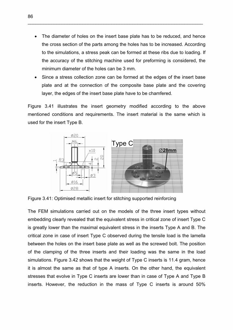
86 ___________________________________________________________________
• The diameter of holes on the insert base plate has to be reduced, and hence
the cross section of the parts among the holes has to be increased. According
to the simulations, a stress peak can be formed at these ribs due to loading. If
the accuracy of the stitching machine used for preforming is considered, the
minimum diameter of the holes can be 3 mm.
• Since a stress collection zone can be formed at the edges of the insert base
plate and at the connection of the composite base plate and the covering
layer, the edges of the insert base plate have to be chamfered.
Figure 3.41 illustrates the insert geometry modified according to the above
mentioned conditions and requirements. The insert material is the same which is
used for the insert Type B.
Type C∅28mm
Figure 3.41: Optimised metallic insert for stitching supported reinforcing
The FEM simulations carried out on the models of the three insert types without
embedding clearly revealed that the equivalent stress in critical zone of insert Type C
is greatly lower than the maximal equivalent stress in the inserts Type A and B. The
critical zone in case of insert Type C observed during the tensile load is the lamella
between the holes on the insert base plate as well as the screwed bolt. The position
of the clamping of the three inserts and their loading was the same in the load
simulations. Figure 3.42 shows that the weight of Type C inserts is 11.4 gram, hence
it is almost the same as that of type A inserts. On the other hand, the equivalent
stresses that evolve in Type C inserts are lower than in case of Type A and Type B
inserts. However, the reduction in the mass of Type C inserts is around 50%
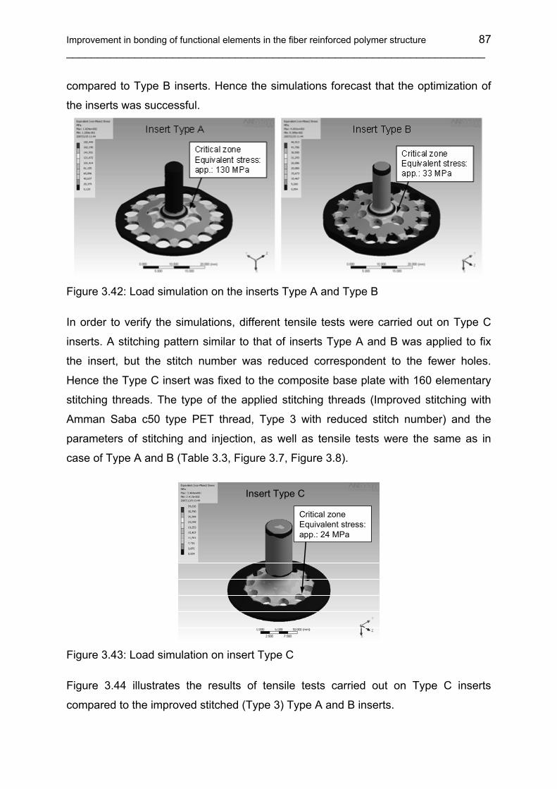
Improvement in bonding of functional elements in the fiber reinforced polymer structure 87 ___________________________________________________________________
compared to Type B inserts. Hence the simulations forecast that the optimization of
the inserts was successful.
Figure 3.42: Load simulation on the inserts Type A and Type B
In order to verify the simulations, different tensile tests were carried out on Type C
inserts. A stitching pattern similar to that of inserts Type A and B was applied to fix
the insert, but the stitch number was reduced correspondent to the fewer holes.
Hence the Type C insert was fixed to the composite base plate with 160 elementary
stitching threads. The type of the applied stitching threads (Improved stitching with
Amman Saba c50 type PET thread, Type 3 with reduced stitch number) and the
parameters of stitching and injection, as well as tensile tests were the same as in
case of Type A and B (Table 3.3, Figure 3.7, Figure 3.8).
Critical zoneEquivalent stress:app.: 24 MPa
Insert Type C
Figure 3.43: Load simulation on insert Type C
Figure 3.44 illustrates the results of tensile tests carried out on Type C inserts
compared to the improved stitched (Type 3) Type A and B inserts.

88 ___________________________________________________________________
0
1000
2000
3000
4000
5000
6000
7000
Type A Type B Type C
Insert type
Max
imum
load
[N]
0
1000
2000
3000
4000
5000
6000
7000
Type A Type B Type C
Insert type
Max
imum
load
[N]
0
50
100
150
200
250
300
350
400
450
500
Type A Type B Type C
Insert TypeM
axim
um lo
adin
rela
tion
to in
sert
mas
s[N
/g]
Figure 3.44: Results of the tensile test on different stitched inserts and the maximum
load in relation to the insert mass (Type of specimen: Type 3)
Insert A, stitched (Type 3)
0
500
1000
1500
2000
2500
3000
3500
4000
4500
5000
0,0 2,0 4,0 6,0 8,0
Displacement [mm]
Forc
e [N
]
First cracking of the resin
Insert C, stitched (Type 3)
0
500
1000
1500
2000
2500
3000
3500
4000
4500
5000
0,0 2,0 4,0 6,0 8,0Displacement [mm]
Forc
e [N
]
First cracking of the resin
Figure 3.45: Cumulated force-displacement diagrams of inserts Type A and C (Type
of specimen: Type 3)
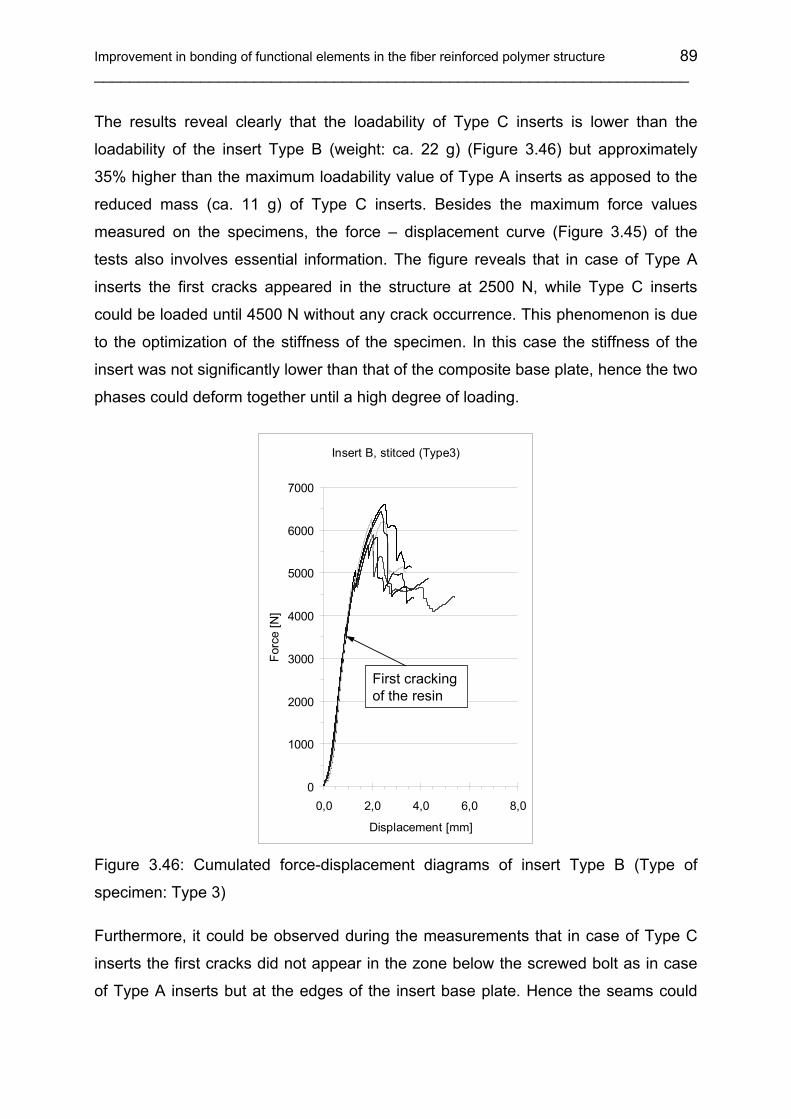
Improvement in bonding of functional elements in the fiber reinforced polymer structure 89 ___________________________________________________________________
The results reveal clearly that the loadability of Type C inserts is lower than the
loadability of the insert Type B (weight: ca. 22 g) (Figure 3.46) but approximately
35% higher than the maximum loadability value of Type A inserts as apposed to the
reduced mass (ca. 11 g) of Type C inserts. Besides the maximum force values
measured on the specimens, the force – displacement curve (Figure 3.45) of the
tests also involves essential information. The figure reveals that in case of Type A
inserts the first cracks appeared in the structure at 2500 N, while Type C inserts
could be loaded until 4500 N without any crack occurrence. This phenomenon is due
to the optimization of the stiffness of the specimen. In this case the stiffness of the
insert was not significantly lower than that of the composite base plate, hence the two
phases could deform together until a high degree of loading.
Insert B, stitced (Type3)
0
1000
2000
3000
4000
5000
6000
7000
0,0 2,0 4,0 6,0 8,0
Displacement [mm]
Forc
e [N
]
First cracking of the resin
Figure 3.46: Cumulated force-displacement diagrams of insert Type B (Type of
specimen: Type 3)
Furthermore, it could be observed during the measurements that in case of Type C
inserts the first cracks did not appear in the zone below the screwed bolt as in case
of Type A inserts but at the edges of the insert base plate. Hence the seams could
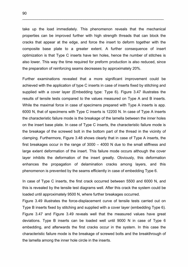
90 ___________________________________________________________________
take up the load immediately. This phenomenon reveals that the mechanical
properties can be improved further with high strength threads that can block the
cracks that appear at the edge, and force the insert to deform together with the
composite base plate to a greater extent. A further consequence of insert
optimization is that Type C inserts have ten holes, hence the number of stitches is
also lower. This way the time required for preform production is also reduced, since
the preparation of reinforcing seams decreases by approximately 20%.
Further examinations revealed that a more significant improvement could be
achieved with the application of type C inserts in case of inserts fixed by stitching and
supplied with a cover layer (Embedding type: Type 6). Figure 3.47 illustrates the
results of tensile tests compared to the values measured on Type A and B inserts.
While the maximal force in case of specimens prepared with Type A inserts is app.
6000 N, that of specimens with Type C inserts is 12200 N. In case of Type A inserts
the characteristic failure mode is the breakage of the lamella between the inner holes
on the insert base plate. In case of Type C inserts, the characteristic failure mode is
the breakage of the screwed bolt in the bottom part of the thread in the vicinity of
clamping. Furthermore, Figure 3.48 shows clearly that in case of Type A inserts, the
first breakages occur in the range of 3000 – 4000 N due to the small stiffness and
large extent deformation of the insert. This failure mode occurs although the cover
layer inhibits the deformation of the insert greatly. Obviously, this deformation
enhances the propagation of delamination cracks among layers, and this
phenomenon is prevented by the seams efficiently in case of embedding Type 6.
In case of Type C inserts, the first crack occurred between 5500 and 6000 N, and
this is revealed by the tensile test diagrams well. After this crack the system could be
loaded until approximately 9500 N, where further breakages occurred.
Figure 3.49 illustrates the force-displacement curve of tensile tests carried out on
Type B inserts fixed by stitching and supplied with a cover layer (embedding Type 6).
Figure 3.47 and Figure 3.49 reveals well that the measured values have great
deviations. Type B inserts can be loaded well until 9000 N in case of Type 6
embedding, and afterwards the first cracks occur in the system. In this case the
characteristic failure mode is the breakage of screwed bolts and the breakthrough of
the lamella among the inner hole circle in the inserts.

Improvement in bonding of functional elements in the fiber reinforced polymer structure 91 ___________________________________________________________________
0
2000
4000
6000
8000
10000
12000
14000
Type A Type B Type CInsert type
Max
imum
load
[N]
0
200
400
600
800
1000
1200
Type A Type B Type CInsert type
Max
imum
load
in re
latio
n to
inse
rt m
ass
[N/g
]
Figure 3.47: Result of the tensile tests on different stitched inserts and the maximum
load in relation to the insert mass (Type of specimen: Type 6)
Insert Type A, with cover layer (Type 6)
0
2000
4000
6000
8000
10000
12000
14000
0,0 2,0 4,0 6,0 8,0 10,0
Displacement [mm]
Forc
e [N
]
First cracking of the resin
Insert Type C, w ith cover layer (Type 6)
0
2000
4000
6000
8000
10000
12000
14000
0,0 2,0 4,0 6,0 8,0 10,0
Displacement [mm]
Forc
e [N
]
Breakage of the screwed bolt
First cracking of the resin
Figure 3.48: Cumulated force – displacement diagram of inserts Type A and C (Type
of specimen: Type 6)
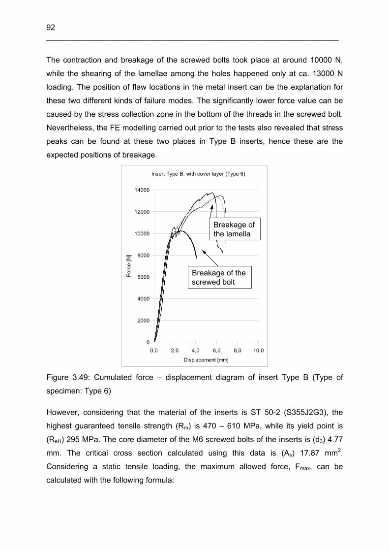
92 ___________________________________________________________________
The contraction and breakage of the screwed bolts took place at around 10000 N,
while the shearing of the lamellae among the holes happened only at ca. 13000 N
loading. The position of flaw locations in the metal insert can be the explanation for
these two different kinds of failure modes. The significantly lower force value can be
caused by the stress collection zone in the bottom of the threads in the screwed bolt.
Nevertheless, the FE modelling carried out prior to the tests also revealed that stress
peaks can be found at these two places in Type B inserts, hence these are the
expected positions of breakage.
Insert Type B, with cover layer (Type 6)
0
2000
4000
6000
8000
10000
12000
14000
0,0 2,0 4,0 6,0 8,0 10,0
Displacement [mm]
Forc
e [N
]
Breakage of the screwed bolt
Breakage of the lamella
Figure 3.49: Cumulated force – displacement diagram of insert Type B (Type of
specimen: Type 6)
However, considering that the material of the inserts is ST 50-2 (S355J2G3), the
highest guaranteed tensile strength (Rm) is 470 – 610 MPa, while its yield point is
(ReH) 295 MPa. The core diameter of the M6 screwed bolts of the inserts is (d3) 4.77
mm. The critical cross section calculated using this data is (As) 17.87 mm2.
Considering a static tensile loading, the maximum allowed force, Fmax, can be
calculated with the following formula:

Improvement in bonding of functional elements in the fiber reinforced polymer structure 93 ___________________________________________________________________
sH AF )(Remax σ= (3.9)
where σ(ReH) is the stress that belongs to the yield point. The maximum allowed force
for this material, obtained this way is app. 5272 N. Hence loading above this value is
not allowed owing to the yield point of the metal insert.
It can be seen that in case of Type C inserts (stitched and supplied with a cover
layer, Type 6 with reduced stitch number), the breakages occurred at app. 5500 N.
This reveals that the allowed maximum loading for the metal insert can be achieved
with the insert – composite connection prepared this way. Hence the insert can be
utilized to a maximum extent, and all the possibilities can be exploited as well.
The modeling of the static tensile test supported the knowing of the actions in the
structure during the tensile load. The simulation of the load on the inserts Type A and
B indicated the disadvantages of the insert architecture. The exploration of these
helps to develop a new type of insert for stitching supported embedding.
3.8 Results of shear tests
F
Specimen withembeddedmetallic insert
Drawhead
Specimen holder
Figure 3.50: Set-up of the shear tests equipment for embedded inserts

94 ___________________________________________________________________
The set-up of the test rig shown in Figure 3.50 was used for shear tests carried out
on inserts Type A. The construction allowed setting the distance of the load
introduction point to the insert (Figure 3.51) and hence the failure modes of
specimens could be studied in each case.
Figure 3.51: Clamping distance (s) between the insert base plate and testing tool
Three measurement series were completed with different clamping distances (s).
Keeping three, six, and nine millimeter distance from the base plate of the insert, it
can be observed that the characteristic failure mode, depending on the type, is pure
shearing (in case of a distance of 3 mm) and shearing as well as bending (in case of
distances of 6 and 9 mm) (Figure 3.52).
Further experiments were carried out at 6 mm work point distance, since this set up
approximates the stress of real loading the best way.
Figure 3.52: Damage modes at different clamping distances (s)
Based on the investigations carried out on unstitched inserts it can be seen that the
characteristic failure mode is the tilting of the insert base plates out of the composite
and the breakage of the base plate (Figure 3.53). It can also be observed that the
inserts cannot slide in the plane of the base plate due to the embedding. The failure
modes reveal the insufficient mechanical properties of the insert base plate.
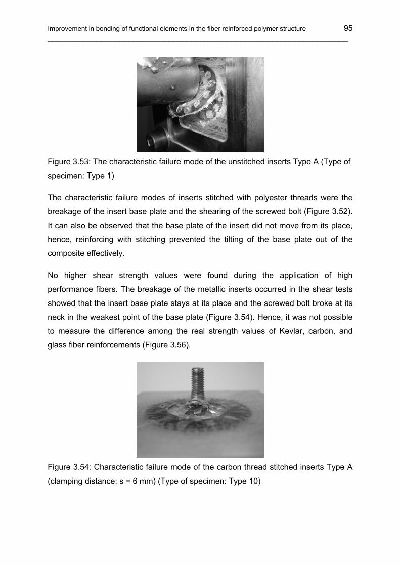
Improvement in bonding of functional elements in the fiber reinforced polymer structure 95 ___________________________________________________________________
Figure 3.53: The characteristic failure mode of the unstitched inserts Type A (Type of
specimen: Type 1)
The characteristic failure modes of inserts stitched with polyester threads were the
breakage of the insert base plate and the shearing of the screwed bolt (Figure 3.52).
It can also be observed that the base plate of the insert did not move from its place,
hence, reinforcing with stitching prevented the tilting of the base plate out of the
composite effectively.
No higher shear strength values were found during the application of high
performance fibers. The breakage of the metallic inserts occurred in the shear tests
showed that the insert base plate stays at its place and the screwed bolt broke at its
neck in the weakest point of the base plate (Figure 3.54). Hence, it was not possible
to measure the difference among the real strength values of Kevlar, carbon, and
glass fiber reinforcements (Figure 3.56).
Figure 3.54: Characteristic failure mode of the carbon thread stitched inserts Type A
(clamping distance: s = 6 mm) (Type of specimen: Type 10)

96 ___________________________________________________________________
The embedded inserts, both in stitched and unstitched states, had such high in-plane
strength that only the shearing of the screwed bolt was the observed failure mode
(Figure 3.55). This reveals that embedding without stitching is sufficient for the
fixation of the insert in case of major shear loading without a significant tension ratio.
Figure 3.55: Characteristic failure mode of embedded inserts (Type A) without
stitching (Type of specimen: Type 5)
As a general result of shear testing it can be concluded that the mechanical shear
performance of an embedded unstitched insert is as good as stitched inserts.
Embedding types0
500
1000
1500
2000
2500
3000
3500
4000
4500
5000
Mea
n Fo
rce
[N]
Type 10, Simple stitching with 1 K iVW CF threadType 8, Improved stitching with Kevlar® threadType 9, Improved stitching with glass threadType 3, Improved stitching with PET threadType 1, Without stitching
138 910
Figure 3.56: Results of the shear tests on specimens with different embedding types,
in case of inserts Type A
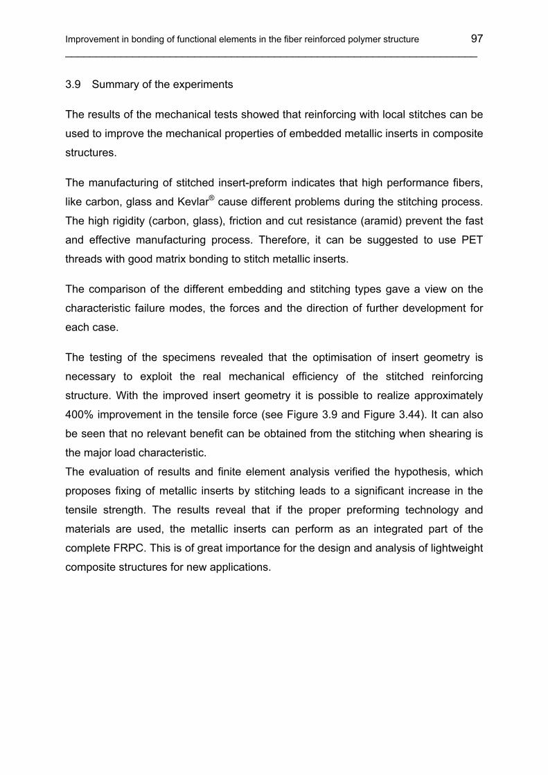
Improvement in bonding of functional elements in the fiber reinforced polymer structure 97 ___________________________________________________________________
3.9 Summary of the experiments
The results of the mechanical tests showed that reinforcing with local stitches can be
used to improve the mechanical properties of embedded metallic inserts in composite
structures.
The manufacturing of stitched insert-preform indicates that high performance fibers,
like carbon, glass and Kevlar® cause different problems during the stitching process.
The high rigidity (carbon, glass), friction and cut resistance (aramid) prevent the fast
and effective manufacturing process. Therefore, it can be suggested to use PET
threads with good matrix bonding to stitch metallic inserts.
The comparison of the different embedding and stitching types gave a view on the
characteristic failure modes, the forces and the direction of further development for
each case.
The testing of the specimens revealed that the optimisation of insert geometry is
necessary to exploit the real mechanical efficiency of the stitched reinforcing
structure. With the improved insert geometry it is possible to realize approximately
400% improvement in the tensile force (see Figure 3.9 and Figure 3.44). It can also
be seen that no relevant benefit can be obtained from the stitching when shearing is
the major load characteristic.
The evaluation of results and finite element analysis verified the hypothesis, which
proposes fixing of metallic inserts by stitching leads to a significant increase in the
tensile strength. The results reveal that if the proper preforming technology and
materials are used, the metallic inserts can perform as an integrated part of the
complete FRPC. This is of great importance for the design and analysis of lightweight
composite structures for new applications.

98
___________________________________________________________________
4 Structural health monitoring of FRPC parts
The aim of sensor integration in composite structures is that they can control the
manufacturing process, the load, the part and the system operation. Load monitoring
can support the optimization of the maintain once intervals and life time, furthermore
the recognition of misuse. Monitoring of aging fiber reinforced polymer composite
(FRPC) structures is a crucial issue in the engineering area [104, 105]. The use of
condition based maintenance coupled with continuous online structural health
monitoring could significantly reduce the costs of inspection programs [106].
“Exclusion-for-cause” instead of “exclusion-as-planned” could reduce the costs while
maintaining a safe operation life. The replacement of the present manual inspection
with automatic health monitoring would substantially reduce the associated lifecycle
costs. Hence there is a need for reliable structural health monitoring (SHM) systems
that can process the data automatically, assess structural conditions and signal the
need for corrective action. Thus, the development of a real-time, in-service structural
health monitoring and damage detection technique has recently attracted a large
number of academic and industrial researchers [107, 108, 109, 110]. The goal of this
researches is to allow systems and structures to monitor their own integrity while in
operation and throughout their life in order to prevent catastrophic failures and to
reduce the costs by minimizing explicit maintenance and inspection tasks.
Figure 4.1 shows the most distributed instruments of the structural health monitoring.
These are the optical sensors [111 ,112 ,113], piezo sensors and actuators [114,
115], the conductive measurement cells [116], and the acoustic sensors [117]. Figure
4.2 presents the function principles of the structural health monitoring methods of the
different SHM instruments. The most popular approach of structural health
monitoring is to use modal parameters, such as natural frequencies, damping ratios
and mode shapes to determine the existence of structure damage. Adams et al. [118]
found that a state of damage could be detected by a reduction in stiffness and an
increase in damping [119]. A method to locate damages from measurements of
natural frequencies was also demonstrated [120].
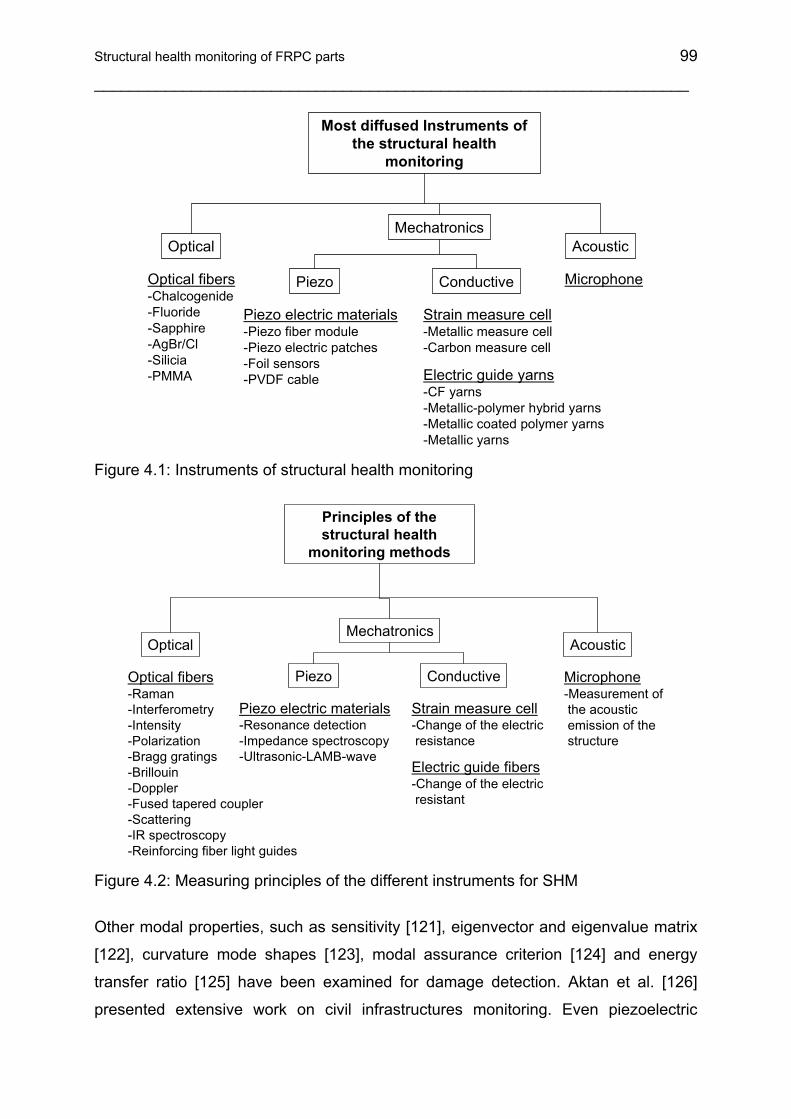
Structural health monitoring of FRPC parts 99
___________________________________________________________________
Most diffused Instruments of the structural health
monitoring
OpticalMechatronics
Conductive
Acoustic
Piezo
Piezo electric materials-Piezo fiber module-Piezo electric patches-Foil sensors-PVDF cable Electric guide yarns
-CF yarns-Metallic-polymer hybrid yarns-Metallic coated polymer yarns-Metallic yarns
Optical fibers-Chalcogenide-Fluoride-Sapphire-AgBr/Cl-Silicia-PMMA
Strain measure cell-Metallic measure cell-Carbon measure cell
Microphone
Figure 4.1: Instruments of structural health monitoring
Principles of the structural health
monitoring methods
OpticalMechatronics
Conductive
Acoustic
Piezo
Piezo electric materials-Resonance detection -Impedance spectroscopy-Ultrasonic-LAMB-wave
Electric guide fibers-Change of the electric resistant
Optical fibers-Raman-Interferometry-Intensity-Polarization-Bragg gratings-Brillouin-Doppler-Fused tapered coupler-Scattering-IR spectroscopy-Reinforcing fiber light guides
Strain measure cell-Change of the electric resistance
Microphone-Measurement ofthe acoustic emission of the structure
Figure 4.2: Measuring principles of the different instruments for SHM
Other modal properties, such as sensitivity [121], eigenvector and eigenvalue matrix
[122], curvature mode shapes [123], modal assurance criterion [124] and energy
transfer ratio [125] have been examined for damage detection. Aktan et al. [126]
presented extensive work on civil infrastructures monitoring. Even piezoelectric

100
___________________________________________________________________
patches can be used not only for monitoring of the resin flow during the resin transfer
molding (RTM) process, but also for lifetime monitoring of FRPC parts [127,128, 129,
130]. Piezoelectric sensors have a number of advantages but disadvantages too,
hence their usability in composite SHM is difficult. The disadvantages are: brittle due
to crystalline structure, cannot withstand high shear and tension, material ages, uses
active control (can lead to instability) and can become depolarized (high voltages,
high temperatures, large stresses). Apart from this, PZT (lead-zirconate-titanate
piezoelectric ceramic material) is a non-reinforcing material, thus, use of matrix
compatible CF thread can be introduced for SHM [131].
In recent years the studies on neural networking [132], wireless active sensing [133],
and wireless monitoring [134] are growing. In composite engineering wireless
monitoring is a very effective method but the costs involved in the implementation of
health monitoring is too high. Thus, development of a cost-effective method is
obligatory. Within this part of the study, carbon fiber threads (IVW-CF thread [135])
have been used as a health monitoring element.
4.1 Carbon fiber patches
In the past, some researches concentrated on the carbon fiber itself as a monitoring
element but mostly the use of carbon UD-fiber patches was preferred.
Smart patches made up of uni-directional (UD) carbon fiber sheets can be used for
damage detection [136]. The change in the electrical resistance of carbon fibers as a
response of impact will be detected by this method.
Figure 4.3 shows the arrangement of carbon fibers and corresponding electrical
conductive elements with varied electrical resistance. The theoretical background is
explained by N. Takeda [137]. The deformation of conductive carbon fibers can be
written as:
ERR
cf
cf σα=∆ (4.1)
where, Rc.f = resistance of carbon fiber; ∆Rc.f = change in the resistance of carbon
fiber; α = constant; σ = stress; E = Young’s modulus.

Structural health monitoring of FRPC parts 101
___________________________________________________________________
Fiber breakage after the impact will be considered as a loss of conducting path. The
amount of fiber volume content affects the effective electrical length, in other words
δec varies for different fiber volume fractions.
)1( −=
cpec N
Lδ (4.2)
Where, δec = electrical ineffective length; L = fiber length; Ncp = number of fiber
contact points (Figure 4.3).
Conductive carbon fiber
Parallel cell as a basic structure of circuit
Serial connection due to the fiber contacts
δec
Contact points as an electrical node
Figure 4.3: Schematics of CF patch and sensing behavior of fiber
The aim of this study is to develop structural health monitoring based on the electrical
properties of carbon fibers. Manufacturing of separate carbon patches requires an
extra process, furthermore, an exact positioning of the patches is necessary. Thus,
within the implemented investigations the benefits of carbon fiber stitching threads
(IVW-CF) have been utilized to validate its usability as a health monitoring element.
The reason behind the selection of IVW-CF threads for the experimentation was
based on laminate performance and consistency in material utilization (only
reinforcing fibers in the structure of the laminate). IVW-CF thread is very thin and
flexible, therefore, it is suitable for stitching composite panels. The special
construction of threads enables them to stitch metallic inserts by forming several
loops without damaging individual carbon filaments. Use of foreign materials as a
sensor system which will be a part of the laminate may affect the laminate properties
adversely. The reason behind that the sensors integrated into the laminate may
disturb the reinforcing fiber orientation. Furthermore, the integrated IVW-CF thread
sensor shows real intensity of damage as these threads represent sections of the

102
___________________________________________________________________
actual load carrying laminate. Apart from this, distribution of carbon threads over the
complete area of the component is easily executable.
Selection of the experimental sensor is based on the goals to be achieved and
allowed time frame for successful development of a sensor system. In this case the
following criteria should be considered:
• Cost of the sensor system and accessories: For the initial trials the costliest
sensor system may not be worthwhile, and furthermore for vast applications of
the sensors, the basic system should be of marginal cost.
• User friendliness: The complete system needs to be easy in monitoring which
helps to detect damages quickly.
• Observation area (effective sensitive area): Observation area depends on the
number of sensors involved in the part, furthermore, IVW-CF threads are
relatively cheap, thus, more can be put into the structure. In this case damage
detection will be easier.
• Robustness: The used sensors should not be damaged during the integration
process. Unlike optical fibers and piezoelectric sensors, CF patches are more
robust and easier to handle during the integration process (for instance during
preforming, stitching, and resin transfer molding).
• Sensitivity: Sensitivity of highly sophisticated sensors is not a question but
when it comes to the robust, user friendly IVW-CF thread sensors; its
sensitivity is not like piezoelectric patches but enough to distinguish generated
signals.
The test plan is based on the carbon fiber reinforced polymer uni-directional-grid,
which will be placed on the glass fiber preforms and the change of the electrical
resistance of carbon fibers will be measured. SEN-T test, metallic insert failure test
and impact test of glass fiber reinforced laminates were performed to prove the utility
of electrical resistance of carbon thread, to analyze debonding of individual stitches
at the insert and its influence on the change in resistance, and rupture of carbon
thread to locate approximate failure location, respectively. All the three tests can
show different aspects of carbon thread utility for structural health monitoring.

Structural health monitoring of FRPC parts 103
___________________________________________________________________
4.2 Selection of material and specimen manufacturing
Carbon fiber thread (IVW-CF) was used as an intelligent monitoring material (Figure
4.4). Plain woven (200 g/m2) and bi-axial non-crimp fabric (NCF 250 g/m2) made of
glass fiber was used as textile reinforcement. Composites were manufactured by
using a low viscosity (120 ±20 mPas) epoxy matrix system Rutepox VE 4908
(producer: Bakelite AG) and vacuum assisted resin transfer molding technique.
1 mm
Figure 4.4: IVW patented carbon fiber hybrid stitching thread [135]
4.3 Preliminary tests
The preliminary test plan is based on the carbon fiber reinforced polymer uni-
directional-grid, which will be placed on the glass fiber preforms and the change of
the electrical resistance of carbon fibers will be measured.
4.3.1 Specimen development for tensile tests
For tensile tests (Single Edge Notched Tensile, SEN-T) a glass fiber woven fabric
has been used as the base material. Preforms were stitched in such way that the
carbon fiber thread position was in a straight line without deviation. Modified lock
stitch gives the advantages of positioning the roving at the bottom of the preform.
Here, a polyester multifilament thread was used as an needle thread and a IVW-CF
thread as a bobbin thread (Figure 4.5).
Stitching parameters used for preform manufacturing are stated in Table 4.1. The
manufactured panels were then injected by means of a liquid matrix based on an
epoxy system. The standard vacuum assisted resin infusion (VARI) method was
used for manufacturing the laminates.

104
___________________________________________________________________
CF hybrid thread
GF NCF base plate
Polyester thread
Metallic insert
Figure 4.5: Modified lock stitch for monolithic laminate and insert monitoring
Lay-up building on the heating plate for the VARI process is the following: a) coating
of release agent; b) stitched preform panel (IVW-CF threads facing top); c) glass fiber
woven fabric; d) perforated foil; e) distribution media (glass fiber mat); f) vacuum foil.
The glass fiber woven fabric (position c) helps avoid direct contact of the IVW-CF
thread and the test instrument in the later stage (Figure 4.6).
Heating plate
a
b
c de
f
Figure 4.6: Lay-up bilding fort he VARI process
Tacky tape was used as a vacuum foil sealing medium.
Table 4.2 shows the parameters set for the VARI process. Manufactured panels were
then cut to the exact size for SEN-T testing.
Table 4.1: Parameters of preform manufacturing Fabric used Glass fiber woven fabric/ noncrimp fabric Stitching machine used Pfaff 3574 Stitch type Modified lock stitch (bobbin thread at the bottom) Stitching speed 1000 1 / min Needle thread force 320 cN Bobbin thread force 140 cN Stitch length 3 mm Smart element IVW-CF thread (used as bobbin thread)

Structural health monitoring of FRPC parts 105
___________________________________________________________________
Table 4.2: VARI process parameters Release agent Freekote Preform material evacuation 10-2 mbar, 1 h Matrix used VE 4908 A + B Degassing of liquid matrix 10 –1 mbar, 10 min Vacuum during infusion 1-10 mbar Injection time 15 min Curing 80°C, 6 h
4.4 Manufacturing of preforms with inserts
Another use of CF patch / thread considered was monitoring the delamination of
metallic inserts. For these tests, inserts and glass fiber non-crimp fabrics (NCF) were
stitched together using polyester multifilament twisted threads. Here, the NCF was
used as a preforming material (see Chapter 3). The IVW-CF thread was used to form
seams at the critical positions which are supposed to be the delamination initiation
zones (Figure 4.5). These seams were connected with a conducting wire, which is
not a part of the whole laminate.
Figure 4.7: Insert (Type A) preform with stitched IVW-CF thread
Figure 4.7 shows a preform stitched with the polyester thread and then with the IVW-
CF thread including electrical connection. Six of such preforms were injected
simultaneously using a special designed tool. The tool helps to inject only the base of
the insert and the reinforcing glass fabric.
Preforms with inserts for delamination sensing were manufactured according to the
measurement reliability. All the stitched preforms were then injected and tested for
the reliability and exactness of measurement.

106
___________________________________________________________________
4.5 Experiments and results
Two different experiments were carried out to observe the application possibilities as
monitoring sensor inherent in the carbon fiber threads. The investigations were the
SEN-T test and the static insert pull out test.
4.5.1 SEN-T test
The schematic view of the specimen and the experimental setup used in this study
are shown in Figure 4.8. A Zwick 1474 tensile testing machine was used for testing.
The machine appears on the principle of constant rate of traverse 0.5 mm/min. The
specimen dimensions are stated in Table 4.3. A specimen is mounted on the
machine and CF threads are internally connected by using electrical wires. Both ends
of a specimen were connected to the signal converter which is connected to the
plotter. As the test progresses, due to applied force, the individual CF thread starts
breaking until the complete specimen fails. A failed specimen is also shown in Figure
4.8.
Table 4.3: Specimen specifications for SEN-T test Width
(W) Length (C) Thickness (B) Notch length (a) Notch width (H) Clamping length (F)
30 mm 110 mm 1 mm 10 +1 mm 1 mm 15 mm
During the failure mechanism, due to the gradual breakage of individual CF threads,
the voltage value increases which can be later calculated in terms of change in
electrical resistance. As shown in Figure 4.9 the force – displacement diagram
correlated with the voltage – time diagram.
The voltage-time diagram is helpful to analyze phenomenon of changes in the
electrical resistance. As shown in the same figure, there is very low electrical
resistance at the initial stage and as the CF threads start breaking the electrical
resistance starts increasing and at the end it converges to infinity.
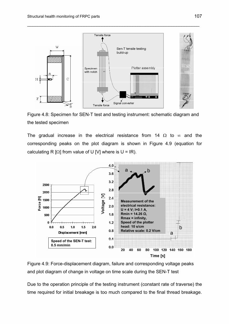
Structural health monitoring of FRPC parts 107
___________________________________________________________________
Figure 4.8: Specimen for SEN-T test and testing instrument: schematic diagram and
the tested specimen
The gradual increase in the electrical resistance from 14 Ω to ∞ and the
corresponding peaks on the plot diagram is shown in Figure 4.9 (equation for
calculating R [Ω] from value of U [V] where is U = IR).
ab
a b
Speed of the SEN-T test: 0.5 mm/min
Measurement of the electrical resistance: U = 4 V; I=0.1 A, Rmin = 14.26 Ω, Rmax = infinity, Speed of the plotter head: 10 s/cmRelative scale: 0.2 V/cm
Figure 4.9: Force-displacement diagram, failure and corresponding voltage peaks
and plot diagram of change in voltage on time scale during the SEN-T test
Due to the operation principle of the testing instrument (constant rate of traverse) the
time required for initial breakage is too much compared to the final thread breakage.

108
___________________________________________________________________
Thus, on the time scale the occurrence of the peak is very quick at the end of the
test, but the change in electrical resistance is still visible. The changes in resistance
of the carbon fibers calculated from the plot diagram are very small but not invisible.
Magnification of signals will be helpful while implementing this technology in the final
product assembly.
This test helps monitor changes in resistance of carbon threads before and after
fracture and thus helps validate the usability of threads as a sensor in the
components subjected to tensile strength or even extreme bending where tensile
force is involved. Broken or elongated carbon threads show higher resistance and
help to conclude intensity of damage corresponding to electrical resistance.
4.5.2 Insert pull out test
IVW-CF thread integrated (stitched) metallic fasteners (Insert Type A) were tested to
monitor delaminations of metallic parts from the glass fiber reinforced polymer
composite. Monitoring the first delamination and the corresponding change in
resistance shown by the CF thread was the basic concept behind this
experimentation. The testing instrument (b) and the close up picture of the test
equipment (c) is shown in Figure 4.10.
a) b) c)
Ω
F
F
Figure 4.10: Insert testing set up: (a) schematics; (b) complete instrument; (c) close
up of the test zone
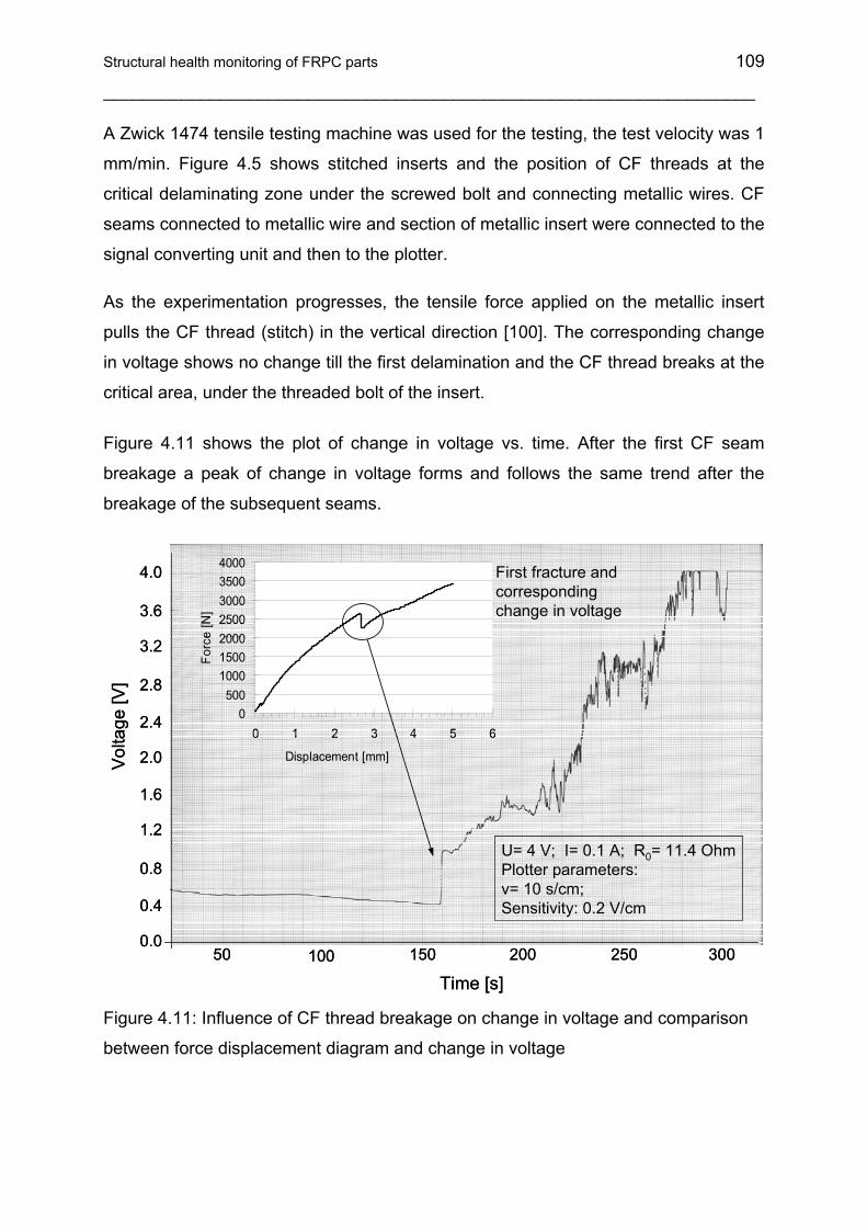
Structural health monitoring of FRPC parts 109
___________________________________________________________________
A Zwick 1474 tensile testing machine was used for the testing, the test velocity was 1
mm/min. Figure 4.5 shows stitched inserts and the position of CF threads at the
critical delaminating zone under the screwed bolt and connecting metallic wires. CF
seams connected to metallic wire and section of metallic insert were connected to the
signal converting unit and then to the plotter.
As the experimentation progresses, the tensile force applied on the metallic insert
pulls the CF thread (stitch) in the vertical direction [100]. The corresponding change
in voltage shows no change till the first delamination and the CF thread breaks at the
critical area, under the threaded bolt of the insert.
Figure 4.11 shows the plot of change in voltage vs. time. After the first CF seam
breakage a peak of change in voltage forms and follows the same trend after the
breakage of the subsequent seams.
0500
1000150020002500300035004000
0 1 2 3 4 5 6
Displacement [mm]
Forc
e [N
]
Time [s]
Vol
tage
[V]
U= 4 V; I= 0.1 A; R0= 11.4 OhmPlotter parameters: v= 10 s/cm; Sensitivity: 0.2 V/cm
150 250 30050 100 2000.0
0.4
1.2
0.8
1.6
2.0
2.4
3.2
2.8
3.6
4.0 First fracture and corresponding change in voltage
0500
1000150020002500300035004000
0 1 2 3 4 5 6
Displacement [mm]
Forc
e [N
]
Time [s]
Vol
tage
[V]
U= 4 V; I= 0.1 A; R0= 11.4 OhmPlotter parameters: v= 10 s/cm; Sensitivity: 0.2 V/cm
150 250 30050 100 2000.0
0.4
1.2
0.8
1.6
2.0
2.4
3.2
2.8
3.6
4.0 First fracture and corresponding change in voltage
Figure 4.11: Influence of CF thread breakage on change in voltage and comparison
between force displacement diagram and change in voltage

110
___________________________________________________________________
Theoretically, the plot should show the sudden deflection on the voltage scale, but
practically the phenomenon of CF thread breakage and possible contact between
broken filaments reveals the progressive deflection of the curve. Figure 4.11 shows
that the first delamination of the insert where the CF thread breaks and the first
voltage rise occurs takes place at the same time.
Incorporation of very little amount of CF thread at the exact damage zone will help
validate the thread usability for integration of metallic inserts in the FRPC laminates.
Strain caused in the CF thread during initial load can also be detected in terms of
minute change in resistance. However, major damage in insert bonding with the main
laminate can be easily detected.
The use of IVW-CF stitching thread as a sensor system for life cycle monitoring and
life expectancy of fiber reinforced composite seams is advantageous. The results of
different tests based on various forms of CF-thread placement shows the
effectiveness of the system. IVW-CF thread works as an integrated part of the
laminate, thus, the influence of the CF thread damage on the change in resistance
helps monitor real fracture impact of the FRPC. The robust nature of sensors and
cost-effectiveness of incorporation processes (process of stitching is relatively cost
effective for sensor mounting and the costs of IVW-CF thread compared to modern
sensing systems is very low) increases the possibility to use these sensors e.g. in
automotive parts. The current monitoring system with CF thread can be made more
accurate by improved connectivity between sensor and monitoring instrument. The
measurement system can be made more user-friendly and accurate. Implementation
of CF sensors only at the critical zones reduces the efforts of monitoring the
complete part area / volume and still provides the required damage information.

Conclusion 111
___________________________________________________________________
5 Conclusion
The aim of the present dissertation is the exploration of the possibilities inherent in
the stitching supported preform technology. It details the different types of stitching
applied in the preform technology, such as joining (preforming), assembly or
structural stitching with the help of examples, according to the basic sorting. As a
manufacturing study, a net shape technology was developed to create a load bearing
stiffening structure. The manufacturing study analyzes the applicability of the
stitching technology and demonstrates a multistage preform manufacturing process,
which facilitates the production of complex, three-dimensional composite parts.
Furthermore, the study revealed that a high-grade automated preform manufacturing
system could be developed, and that allows not only a net-shape manufacturing
process but it can help to achieve a quality controlled manufacturing as well.
As a next step, a three-dimensional preform manufacturing process was worked out
with different low melting temperature thermoplastic stitching threads. With the
application of this technology the advantages of the binder technology and the
stitching supported preforming can be alloyed. Thus a shape-retaining ready-to-
impregnate three-dimensional preform, the application of which simplifies the
handling and the positioning of the preform into the injection tool, can be formed.
Quantitative measurement methods were worked out to reveal the mechanical
properties of the fusible thread stitched three-dimensional preforms. These
measurement methods indicate the effect of the orientation and density of the
stitching in the reinforcing structure after thermal treatment. Three basic properties of
the thermoformed preforms were tested: the specific bending stiffness, the spring
back angle after thermoforming, and the restoring force in case of different material
architectures and stitching types. The most important material property of the joining
stitching threads besides the low melting point is the solubility essentially in
unsaturated polyester and epoxy resins. With the matrix solubility, it is possible to
ensure the dissolution of the threads after they accomplished the binding function.
Stitch holes from the preforming can be removed with this effect, and the reduction of
the mechanical properties degradation of the composite parts can be ensured. With
the help of the investigations two polymeric threads were selected, the melting
temperature of these polymers is less than 100 °C, they show good solubility
properties, and have the mechanical properties required for stitching.

112
___________________________________________________________________
The stitches can be applied in the structure for not only joining or assembly function
but also can be the essential elements of the reinforcement structure. These are
called as structural stitching, the essentially function of which is the interlaminar
reinforcement in monolithic or sandwich structures. These also have great
possibilities to use for fixation of metallic load transmission elements in composite
structures. The static tensile tests carried out on stitched transmission elements
(inserts) showed that app. 200% improvement of maximal load force could be
achieved against the unstitched BigHead® inserts. The investigations revealed that
the highest reinforcing effect could be achieved through the simultaneous
interlaminar embedding and stitching of the inserts. In this case, the reinforcing
stitching can prevent the delamination of the composite layers that is the
characteristic failure mode in case of interlaminar embedded inserts. The static shear
tests carried out on the embedded metallic inserts gave a possibility to observe the
characteristic failure modes and the evaluation of the stitching technique supported
reinforcing. Since the characteristic failure mode of the stitched inserts was not the
damage of the stitching thread but the insert breakage, the next step of the
investigations was the development of a new insert with modified base plate
geometry. The application of this insert type enables the testing of the real loadability
of the stitching threads. The results revealed that the high performance stitching
threads as glass carbon or aramid can only be applied with restrictions to fixed
inserts, while polyester (PET) threads show adequate reinforcing properties. As the
next step the finite element modeling of the insert-composite contact and the
optimization of the metallic insert geometry were accomplished.
Through the electric conductivity of the fibers, the carbon stitching threads can be
used as sensors for structural health monitoring. The investigations carried out on
carbon thread stitched composite parts indicated that the damage in the composite
structure could be detected through the change in electric resistance of carbon
threads. The results of the investigations revealed that carbon threads are adaptable
not only as reinforcement but also as sensors of the damage in metallic inserts.
The research carried out in frame of the present work indicates the large potential
inherent in the stitching supported preform technology. The results verify that the
adorning the stitching threads with additional functions ensure further extensive
possibilities in the applications of preform technology.
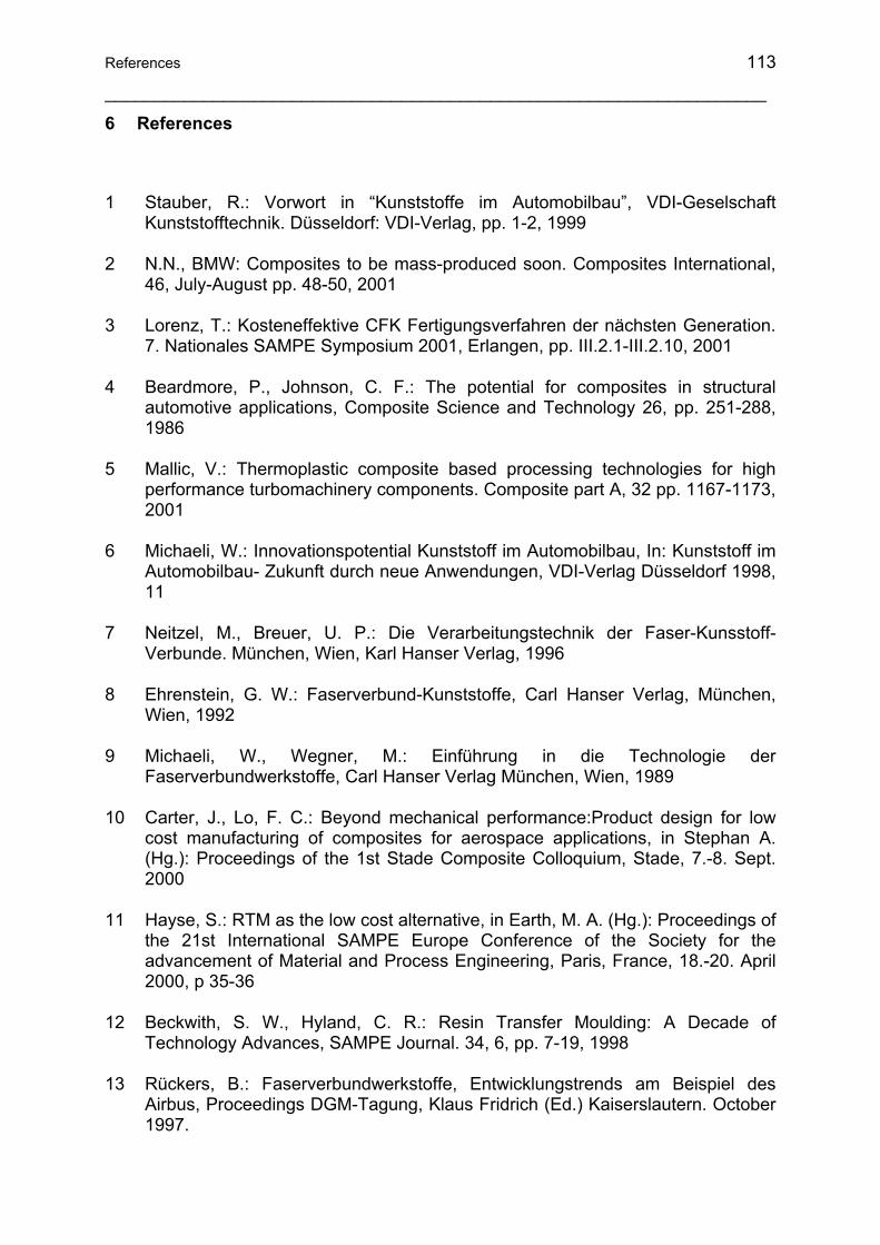
References 113
___________________________________________________________________
6 References
1 Stauber, R.: Vorwort in “Kunststoffe im Automobilbau”, VDI-Geselschaft Kunststofftechnik. Düsseldorf: VDI-Verlag, pp. 1-2, 1999
2 N.N., BMW: Composites to be mass-produced soon. Composites International, 46, July-August pp. 48-50, 2001
3 Lorenz, T.: Kosteneffektive CFK Fertigungsverfahren der nächsten Generation. 7. Nationales SAMPE Symposium 2001, Erlangen, pp. III.2.1-III.2.10, 2001
4 Beardmore, P., Johnson, C. F.: The potential for composites in structural automotive applications, Composite Science and Technology 26, pp. 251-288, 1986
5 Mallic, V.: Thermoplastic composite based processing technologies for high performance turbomachinery components. Composite part A, 32 pp. 1167-1173, 2001
6 Michaeli, W.: Innovationspotential Kunststoff im Automobilbau, In: Kunststoff im Automobilbau- Zukunft durch neue Anwendungen, VDI-Verlag Düsseldorf 1998, 11
7 Neitzel, M., Breuer, U. P.: Die Verarbeitungstechnik der Faser-Kunsstoff-Verbunde. München, Wien, Karl Hanser Verlag, 1996
8 Ehrenstein, G. W.: Faserverbund-Kunststoffe, Carl Hanser Verlag, München, Wien, 1992
9 Michaeli, W., Wegner, M.: Einführung in die Technologie der Faserverbundwerkstoffe, Carl Hanser Verlag München, Wien, 1989
10 Carter, J., Lo, F. C.: Beyond mechanical performance:Product design for low cost manufacturing of composites for aerospace applications, in Stephan A. (Hg.): Proceedings of the 1st Stade Composite Colloquium, Stade, 7.-8. Sept. 2000
11 Hayse, S.: RTM as the low cost alternative, in Earth, M. A. (Hg.): Proceedings of the 21st International SAMPE Europe Conference of the Society for the advancement of Material and Process Engineering, Paris, France, 18.-20. April 2000, p 35-36
12 Beckwith, S. W., Hyland, C. R.: Resin Transfer Moulding: A Decade of Technology Advances, SAMPE Journal. 34, 6, pp. 7-19, 1998
13 Rückers, B.: Faserverbundwerkstoffe, Entwicklungstrends am Beispiel des Airbus, Proceedings DGM-Tagung, Klaus Fridrich (Ed.) Kaiserslautern. October 1997.

114
___________________________________________________________________
14 N.N.: RTM Moves Ahead, Reinforced Plastics, pp. 26-33, 1997
15 N. N.: HTMA Market Forecast, High Tech Materials Alert, 7, pp. 5-6, 1997
16 N. N.: Process Refinement Key to RTM Succes, Reinforced Plastics, 2, pp. 26-30, 1999
17 Fabio, R., Rao, N.: Experiences with Exterior Composites on the DaimlerChrysler viper andProwler Programs, Proceedings „Praxis-Forum-Tagung: The 2010 Plastic car Body Vision“, Ebert F., Woydt M. (Ed.) Bad Nauheim. Germany, pp. 355-366, 1999
18 Wallentowittz, H., Adam, H., Bröckling, J.: Potential of fiber reinforced plastics space frame structures. VDI-Tagung Entwicklung im Karosserienbau, Hamburg, 14.,15. Mai 1996, p. 477-495
19 Beckwith, S. W.: RTM, VARTM, and SCRIMP processing infusion technologies. SAMPE 44th ISSE / SAMPE 99´, Long Beach, CA, 05. 1999, Beckwith Technology Group, Murray, Utah, 1999
20 Fleming, M., Ziegmann, G., Roth, S.: Faserverbundbauweisen, Fasern und Matrices, Springer Verlag, Berlin, Heidelberg, 1995
21 Fleming, M., Ziegmann, G., Roth, S.: Faserverbundbauweisen, Halbzeuge und Bauweisen, Springer Verlag, Berlin, Heidelberg, 1996
22 Fleming, M., Ziegmann, G., Roth, S.: Faserverbundbauweisen, Fertigungsverfahren mit duroplastischer Matrix, Springer Verlag, Berlin, Heidelberg, 1999
23 Chavka, N. G, Dahl, J.-S.: P4: Glass Fiber Preforming Technology for Automotive Application. Resin Transfer Molding SAMPE Monograph No. 3, SAMPE Publications, Corvina, 1999
24 Büsgen, W.-A.: Neue Verfahren zur Herstellung von dreidimensionalen Textilien für den Einsatz in Faserverbundwerkstoffen, Dissertation RWTH, Aachen, 1993
25 Feltin, D.: Neue textile Preformtechniken zur kostengünstigen FV-Bauteilherstellung. 2. Internationale AVK-Tagung für verstärkte Kunststoffe und Formmassen, Baden-Baden, pp. B 10, 12.-13- Okt. 1999
26 Bogdanovich, A., Singletary, J.: 3-D Woven Preforms and Composites: Experimental Characterization and Predictive Analysis, Proceedings of the 5th International Conference on Textile Composites, Leuven, 18.-20. September 2000, p4
27 Kobayashi, H., Nakama, N.: Fabrication of mechanical properties of Braided Composite Truss Joints. Proc. Of the 36th International SAMPE Symposium, pp. 1089-1103, 1992

References 115
___________________________________________________________________
28 Kendal, M.: Keynote on Textile Composites for Automotive Applications. ACP 2000. Automotive Composites and Plastics. Essex, 5.-6. December 2000
29 Wiedmer, S.: Zur Pultrusion von thermoplastischen Halbzeugen: Prozessanalyse und Modellierung, Dissertation, IVW, Kaiserslautern, 2006
30 Bibo, G. A., Hogg, P. J., Backhouse, R, Mills A.: Carbon fiber non crimp fabric laminates for cost effective damage-tolerant structures. Composites Science and Technology, 58, pp. 129-143, 1998
31 Warrior, N. A., Rudd, C. D., Gardner, S. P.: Experimental studies of embroidery for the local reinforcement of composites structures 1. Stress concentrations. Composite Science and Technology , Vol 59, pp. 2125-2137, 1999
32 Matheij, P., Gliesche, K., Feltin, D.: Tailored fiber placement – Mechanical properties and applications. Reinforced Plastics and Composites, Vol. 17, 9, pp. 774-787, 1998
33 Hörsting, K., Huster, M,.: Maßgeschneiderte Verstärkungstextilien für Verbundwerkstoffe, in DWI Reports (Hg.): Aachener Textiltagung. Aachen, pp. 190-201, 25.-26. November 1998
34 Bischof, T. H., Wulfhorst, B.: Rundwirke mit multiaxialen Stehfäden für neue Anwendungsgebiete. Technische Textilien, Vol. 42, pp.151-153, 1999
35 Laourine, E., Schneider, M., Wulfhorst, B.: Production and Analysis of 3D Braided Textiles Preform for Composite. Proceedings of the 5th International Conference on Textile Composites, Louvain, 18.-20. September 2000, p. 4
36 Witting, J.. Roboted 3-dimensional Stitching Technology, Stephan A. (Hg.): Proceedings of the 1st Stade Composite Colloquium, Stade, 7.-8. September 2000
37 Keilmann, R., Jäger, M.: Präsentation Blindstitchtechnologie, in Stephan A. (Hg.): Proceedings of the 1st Stade Composite Colloquium, Stade 7.-8 september 2000
38 Palmer, R. J., Dow, M. B., Smith, D. L.: Development of Stitching Reinforcement for Transport Wing Panels, 1 st NASA Advanced Composite Technology Conference, Seattle, WA, 29.10.-1.11.1990, NASA CP-3104, Part 2, pp. 621-646, 1990
39 Mouritz, A. P., Leong, H. K., Herszberg, I.: A review of the effect of stitching on the in-plane Mechanical Properties of Fibre-Reinforced Polymer Composites. Composite Part A, 28 A, pp. 979-991, 1997
40 Mouritz, A. P., Cox, B. N.: A Mechanistic Approach to the Properties of Stitched Laminates. Composite Part A, Vol. 31 1, pp. 1-27, 2000

116
___________________________________________________________________
41 Mignery, L. A., Tan, T. M., Sun, C. T.: Use of Stitching to Suppress Delamination in Laminated Composites, In Johnson, W.S.: Delamination and Debonding, AST STP 876. Philadelphia: American Society for Testing and Materials, 1985, p. 371-385
42 Cahuzac, G., His, S.: AEROTISS 4.5D – A New Technology for Thick Multiply Composite Panels, in Earth, M. A. (Hg.): Proceedings of the 21st International SAMPE Europe Conference of the Society for the Advancement of material and Proces Engineering, Paris, France, 18.-20. April 2000, p. 233-241
43 Chung, W. C., Jang, B. Z., Chang, T. C., Hwang, L. R., Wilcox, R. C.: Fracture Behavior in Stitched Multidirectional Composites. Materials Science and Engineering (1998), A 112, p. 157 173
44 Mouritz, A. P., Jain, L. K.: Further Validation of the Jain and Mai Models for Interlaminar Fracture of Stitched Composites. Composites Science and Technology, Vol. 59, p. 1653-1662, 1999
45 Parnas, R. S.: Liquid Composite Molding. München, Hanser Gardner, 2000
46 Dexter, H. B.: Development of Textile Reinforced Composites for Aircraft Structures. Proceeding of the 4th international Symposium for textile composites, Kyoto, Japan 12-14 October 1998, pp.0-32-1 – 0-32-8.
47 Williams, C., Summerscales, J., Grove, S.: Resin Infusion under Flexible Tooling (RIFT), A review. Composites Part A, Vol. 27 A (1996), p. 517-524
48 Single, C.: Neue kostengünstige Fertigungsferfahren für CFK-Strukturen. 4. Nationales SAMPE Symposium, Braunschweig 12.-13. März 1998, p. 1-15
49 Single, C.: Ein Beitrag zur kostenoptimierten Herstellung von großflächigen Hochleistungsverbundbauteilen. Dissertation TU Braunschweig 1998
50 Neitzel, M., Mitschang, P.: Handbuch Verbundwerkstoffe, Carl Hanser Verlag, 2004.
51 Mitschang, P., Ogale, A., Schlimbach, J., Weyrauch, F., Weimer, C.: Preform Technology: a Necessary Requirement for Quality Controlled LCM-Processes. Polymers & Polymer Composites, No. 8, Vol. 11, pp. 605 – 622, 2003
52 Klopp, K.; Moll, K.-U.: Stitching process with one-sided approach of the textile for the production of reinforcing textiles for composites and other technical textiles. Proceedings 5th International Conference on Textile Composites, 18-20 September, 2000, Leuven, Belgium, p. 4.
53 Ogale, A., Weimer, C., Ladstätter, E., Billinger, W.: A presentation on: Compaction behavior of stitched fabric preforms. European Congress on Advanced Materials and Processes (EUROMAT), Lausanne, Switzerland, 1-5 September 2003.

References 117
___________________________________________________________________
54 Adanur, S., Tsao, Y. P.: Stitch bonded textile structural composites 26th International SAMPE Technical Conference October 17-20, 1994
55 Mitschang, P. (Hrsg.): Prozessentwicklung und ganzheitliches Leichtbaukonzept zur durchgängigen, abfallfreien Preform-RTM Fertigung (Pro-Preform RTM – Abschlussbericht, IVW – Schriftenreihe, Band 46) 2004
56 FORD GLOBAL TECHNOLOGIES, INC.: Robotic systems for automated preform processing, United States Patent US 6497 566, 2002
57 http://www.aplicator.se/prod/p4.htm
58 Brandt, M. R., Reeve, S. R.: Direct Fiber Preform Case Studies, Composites 2001 Convention and Trade Show, Composites Fabrications Association, Tampa, FL USA, October 3-6, 2001
59 DIN 53362: Prüfung von Kunststoff-Folien und von textilen Flächengebilden (außer Vliesstoffe), mit oder ohne Deckschicht aus Kunststoff-Bestimmung der Biegefestigkeit- Verfahren nach Cantilever, 2003-10
60 Pascault, J.-P., Sautereau, H., Verdu, J., Williams, R. J. J.: Thermosetting Polymers, 2002 Marcel Dekker, Chapter 10, pp. 282-322
61 Carraher, C. E., Seymour, R., B.: Polymer Chemistry, 2003 Marcel Dekker, Chapter 3, pp. 61-73
62 Wolf, B. A.: Solubility of Polymers, Pure and Applied Chemistry, 57, 2, pp. 323-336, IUPAC, 1985
63 Gossens, S., Goderis, B., Groeninckx, G.: Reaction-Induced Phase Separation in Crystallizable Micro- and Nanostructured High Melting Thermoplastic/Epoxy Resin Blends, Macromolecules 2006, 39, pp. 2953-2963
64 Peng, M., Li, H., Wu, L., Chen, Y., Zheng, Q., Gu.: Organically Modified Layered-Silicates facilitate the Formation of Interconnected Structure in the Reaction-Induced Phase Separation of Epoxy/Thermoplastic Hybrid Nanocomposite, Polymer 46, 7612-7623, Elsevier 2005
65 Fernandez, B., Arbelaiz, A., Diaz, E., Mondragon, I.: Influence of Polyethersulfone Modification of a Tetrafunctional Epoxy Matrix on the Fracture Behavior of Composite Laminates Based on Woven Carbon Fibers, Polymer Composites 25, 480-488, 2004
66 Giannotti, M. I., Mondragon, I., Galante, M. J., Oyanguren, P. A.: Morphology profiles obtained by reaction-induced phase separation in epoxy/polysulfone/poly(ether imide) systems, Polymer International 54 pp. 897-903, 2005
118
___________________________________________________________________
67 Gianotti, M. i., Bernal, C. R., Oyanguren, P. A., Galante, M. J.: Morphology and Fracture Properties Reationship of Epoxy-Diamin Systems Simultaneously Modified With Polysulfone and Poly(ether imide), Polymer Engineering and Science 45, pp. 1312-1318, 2005
68 Terjack, A., Remiro, P. M., Mondragon, I.: Phase Separation and Rheological Bahavior During Curing of an Epoxy Resin Modified With Syndiotactic Polystyrene, Polymer Engineering and Science, 45, pp. 303-313, 2005
69 Vanden, Poel R., Goossens, S., Goderis, B., Groeninckx, G.: Reaction Induced Separation in Semicrystalline Thermoplastic/Epoxy Resin Blends, Polymer 46 pp. 10758-10771, 2005
70 Chen, C.-C., Chen, Y.-C., Shen, K.-S., Yu, T. L.: Phase Separation of Poly(ether sulfone imide) Modified Epoxy Resins, Journal of Polymer Research 10, pp. 39-46, 2003
71 Munz, M., Sturm, H., Stark, W.: Mechanical Gradient Interphase by Interdiffusion and Antiplasticisation Effect-Study of an Epoxy/Thermoplastic System, Polymer 46, pp. 9097-9112, 2005
72 Wylen G. J., Sonntag R. E., Borgnakke C., Borgnakke C.: Fundamentals of Classical Thermodynamics, John Wiley and Sons (WIE), 1994
73 Van Krevelen, D. W.: Properties of Polymers, Elsevier 1997, Chapter 7, pp. 189-225
74 Schievenbusch, F.: Beitrag zu Hochbelasteten Krafteinleitungselementen für Faserverbundbauteile, Dissertation TU Chemnitz, FMV, 2003
75 Habenicht, G.: Kleben: Grundlagen, Technologie, Anwendungen, Springer-Verlag 1990. Kap. 8 Festigkeiten von Metallklebungen, pp. 270-350
76 Sasdelli, M., Karbhari, V. M., Gillespie, J. W.: On the use of metal inserts for attachment of composite components to structural assemblies-a review, International Journal of Vehicle Design, 14,4, pp. 353-369 1993
77 Matthews, F. L.: Joining Fibre Reinforced Plastics, Elsevier, London, New York, 1987
78 Hart-Smith, L. J.: Mechanically fastened joints for Advanced Composites-Phenomenological Considerations and Simple Analysis, Fibrous Composites in Structural Desingn, Plenum Press, New York, 1980
79 Hart-Smith, L. J.: Bonded-Bolted Composite Joints, Journal of Aircraft, 22, 11, pp. 993-1000, 1985
80 Müller, W.: Krafteinleitung in Faserverbundwerkstoffe-Hinweise für Zukunft- und Fertigungsgerechten Gestaltung, Dissertation, RWTH Aachen, 1991

References 119
___________________________________________________________________
81 Grüninger, G.: Möglichkeiten der Krafteinleitung in Faserverstärkte Bauteile, Kunststoff- und Aramidfaserverstärkte Kunststoffe, VDI-Verlag, Düsseldorf 1997
82 Hütter, U.: Probleme der Krafteinleitung in Glasfaser-Kunststoff-Bauteile, Kunststoffe. 56, 12, pp. 843-846, 1966
83 Hart-Smith, L.J.: Further Developments in the Design and Analylsis of Adhesive-Bonded Structural Joints, ASTM Conference on Joining of Composite Materials (STP 749), Minneapolis Minnesota, 1980
84 Sasdelli, M., Karbhari, V. M.: The Design and Use of Molded-in Inserts and Attachments in Resin Transfer Molding, Proc 8th Annual ASM/ESD Conference, pp. 407-413, 1992
85 Ferret, B., Anduze, M., Nardari, C.: Metal Inserts in Structural Composite Materials Manufactured by RTM, Composite Part A 29, A, pp. 693-700, 1998
86 Freitag, P.: Metallische Gewindeeinsätze für Thermo- und Duroplaste, Plastverarbeiter 42, 9, pp. 60-66, 1991
87 Hoa, S.V., Lulham, I., Sankar, T. S.: Aluminium Inserts for Fastening Sheet Moulding Compounds, Proceedings 3rd Int. Conf. Composite Structures, Paisley, Scotland, pp. 575-583, 1985
88 Hoa, S. V., Di Maria, A.: Metal Inserts for Efficient Joining of Sheet Molding Compoud Structures, Proc. Of the 4th Annual Conference on Advanced Composites, Dearborn, Michigan, 1988
89 Schwarz, M.; Magin, M.; Peil, C.; Schürmann, H.: Thin-walled FRP-laminates and local bending moments incompatible or solvable by a skillful design? Proceedings 7. Internationale AVK-TV Tagung, Baden-Baden, September 2004.
90 Trinter, F., Ehrenstein, G. W.: Mechanisches Verbinden von Bauteilen aus SMC mit umpressten Gewindeeinsötzen, AVK-Tagung, pp. 19.1-7, 1987
91 Trintner, F., Ehrenstein, G. W.: Schraubenverbindungen mit Gewindeeinsätzen und gewindeerzeugenden Schrauben an Bauteilen aus faserverstärkten Fließpresswerkstoffen, VDI-Bericht 852, VDI-Verlag, Düsseldorf, pp. 493-510, 1991
92 Evans, R. L.; Heller, M.: Effect of Bonded insert Shape and Adhesive Thickness on Critical Stresses in a Loaded Plate, DSTO Aeronautical and Maritime research Laboratory, Melbourne Victoria 3001, August 1996, p. 1.
93 Mignery, L. A., Tan, T. M., Sun, C. T.: The use of stitching to suppress delamination in laminated composites. Delamination and debonding, ASTM STP 876, ed. W. S. Johnson, American Society of Testing and Materials, Philadelphia, PA, pp. 371-81, 1985.

120
___________________________________________________________________
94 Skelton, T. J.: Localized Stitching to Reinforce Inserts in Composite Sandwich Panels, M.S. Thesis, Department of Mechanical Engineering, University of Utah, Salt Lake City, UT, December 2004.
95 Roth, M. A.: Strukturelles Nähen: Ein Verfahren zur Armierung von Krafteinleitungen für Sandwich-Strukturen aus Faser-Kunststoff- Verbund, Dissertation IVW GmbH Kaiserslautern 2006
96 Ogale, A., Weimer, C., Mitschang, P.: Selection of sewing threads for preform manufacturing, Advanced composite letters No. 4 (2004), Vol. 13, pp. 145-153.
97 Mitschang, P.: Faser-Kunststoff-Verbund-Bauteil mit Inserts, OS DE 198 34 772 A1, 1. August 1998.
98 Ogale, A., and Mitschang, P.: Tailoring of textile preforms for fibre-reinforced polymer composites, Journal of industrial textiles No. 2 (2004), Vol. 34, pp 77-96.
99 Brandau, E.: Duroplastwerkstoffe: Technologie, Prüfung, Anwendung, VCH Verlag 1993.
100 Molnar, P., Ogale, A., Mitschang, P.: Incorporation of Functional Elements into the Fibre Reinforced Polymer Structure by Means of Tailoring Technology. Proceedings Reinforced Plastics International Balaton Conference, Balatonvilágos 2004.
101 Zienkiewicz, O. C., Taylor, R. L.: The Finite Element Method for Solid and Structural Mechanics, Butterworth-Heinemann; 6 edition (September 20, 2005)
102 Zienkiewicz, O. C.: Methode der finiten Elemente, Carl Hanser Verlag München, Wien 1975, pp. 17-29
103 Kollár, P. L., Springer S. G.: Mechanics of Composite Structures, Cambridge University Press 2003, pp.18-20. and 50-61.
104 Van der Auweraer H., Peeters B.: International Research Projects on Structural Health Monitoring: An Overview. SHM - Structural Health Monitoring. Vol. 2. pp. 341-358. 2003
105 Kalamkarov, Saha, Georgiades, Challagulla, Newhook: Smart FRP Reinforcements for Long-term Health Monitoring in Infrastructure. Journal of Thermoplastic Composite Materials. Vol. 17. S. 359-381. 2004
106 Kessler, S. S.; Sperling, S. M.: Structural Health Monitoring of Composite Materials Using Piezoelectric Sensors, internet web page: http://web.mit.edu/sskess/www/papers/materials_evaluation.pdf. (accessed on August 14. 2004
References 121
___________________________________________________________________
107 Wang, Q., Quek, S. T.: A Model of the Analysis of Beams with Embedded Piezoelectric Layers. Journal of Intelligent Material Systems and Structures. Vol. 13. S. 61-70. 2002
108 Ping, T., Liyong, T.: A delamination detection model for composite beams using PFRC sensor/actuator. Composites Part A: Applied Science and Manufacturing. pp. 231-247. 2004
109 Qing, Beard, Kumar, Chan, Ikegami: Advances in the development of built-in diagnostic system for filament wound composite structures. Composites Science and Technology. Vol. 66. pp. 1694-1702. 2006
110 Giurgiutiu, Zagrai, Bao: Piezoelectric Wafer Embedded Active Sensors for Aging Aircraft Structural Health Monitoring. SHM - Structural Health Monitoring Vol. 1. pp. 41-61. 2002
111 Gerard, F. F.: Fibre optic sensor systems for monitoring composite structures. Reinforced Plastics. S. 41-49; 2005
112 Skontorp, A.: Composites with Embedded Optical Fibers at Structural Details with Inherent Stress Concentrations. Journal of Composite Materials 22. S. 2501-2515, 2002
113 Betz, Staudigel, Trutzel, Kehlenbach: Structural Monitoring Using Fiber-optic Bragg Grating Sensors. SHM - Structural Health Monitoring. Vol. 2. S. 145-152. 2003
114 Brei, D., Cannon, B. J..: Piezoceramic hollow fiber active composites. Composites Science and Technology. S. 245-261. 2004
115 Pohl, J.: Zerstörungsfreie Charakterisierung adaptiver CFK-Piezokeramik-Verbunde. ZfP-Zeitung 87. pp. 37-42. 2003
116 Horoschenkoff, A.: Strukturintegrierte DMS für Faserverbundwerkstoffe. FH München, Kunststofftechnik Online Seminar, http://www.lrz-muenchen.de/~p3001gu/webserver/webdata/3_semina/v3_piezo/38_piezo.htm, 2004
117 Travis, L. T.: Structural acoustic response of a shape memory alloy hybrid composite panel (lessions learned). SPIE's Annual International Symposium on Smart Structures and Materials. San Diego, 17.-21. März 2002. NASA Langley Research Center
118 Adams, R. D.; Cawley, P.; Pye, C. J.; Stone, B. J.: A Vibration Technique for Non-Destructively Assessing the Integrity of Structures. Journal of Mechanical Engineering Science, Vol. 20, No. 2, pp. 93-100, 1978
119 Gachagan, A., Hayward, G., Banks, R.: A Flexible Piezoelectric Transducer Design for Efficient Generation of Reception of Ultrasonic Lamb Waves. IEEE

122
___________________________________________________________________
Transactions on Ultrasonics, Ferroelectrics, and Frequency Control. Vol. 52. pp. 1175-1182. 2005
120 Cawley, P.; Adams, R. D.: The Location of Defects in Structures from Measurements of Natural Frequencies, Journal of Strain Analysis, Vol. 14, No. 2, pp. 49-57, 1979
121 Adelman, H. M.; Haftka, R. T.: Sensitivity Analysis of Discrete Structural systems”, AIAA Journal, Vol. 24, No. 5, pp. 823-832, 1986
122 Zimmerman, D. C.; Kaouk, M.: Structural damage detection using a minimum rank update theory. ASME Journal of Vibration and Acoustics, Vol. 116, No. 2, pp. 222-231, (1994).
123 Pandey, A., Biswas, K. M.; Samman, M.: Damage detection from changes in curvature mode shapes. Journal of Sound and Vibration, Vol. 145, No. 2, pp. 321-332, (1991).
124 Samman, M. M.: Structural damage detection using the modal correlation coefficient (MCC). Proceedings of the 15th International Modal Analysis Conference, Orlando, FL, pp. 627-630, (1997).
125 Liang, Z., Lee, G. C.; Kong, F.: On Detection of Damage Location of Bridges. Proceedings of the 15th International Modal Analysis Conference, Orlando, FL, pp. 308-312, (1997).
126 Aktan, A. E., Brown, D. L., Farrar, C. R., Helmicki, A., Hunt, V., Yao, J.: Objective global condition assessment. Proceedings of the 15th International Modal Analysis Conference, Orlando, FL, pp. 364-373, 1997
127 Stöven, T., Wang, X., Neitzel, M., Mitschang, P.: Monitoring the Resin Transfer Molding Process by Piezoelectric Elements, Processing Online Sensing and Control for Liquid Molding of Composite Structures, Steiner, K.V., Advani S.G. (Eds.), Annapolis, MD / Apr. 14-15, CCM
128 Hillger, W.: Lamb-Wellen zur Schadensanzeige in faserverstärkten Kunststoffen. DGZfP Jahrestagung 2005. Rostock, 2.-4. Mai 2005
129 Park, G., Sohn, H., Farrar, C. R., Inman, D. J.: Overview of Piezoelectric Impendance-Based Health Monitoring and Path Forward. The Shock and Vibration Digest No. 6. pp. 451-463. Vol. 35. 2003
130 Park, Kabeya, Cudney, Inman: Impendance-Based Structural Health Monitoring for Temperature Varying Applications. JSME International Journal No. 2. 42/1999. pp. 249-258
131 Haase, Pusch, Laourine, Cherif, Illing-Günther, Zschenderlein, Möhring, Fritzsche, Haiduk, Nowottne: Energie und Informationsübertragung in Smart Textiles. Technische Textilien. pp. 256-259. 2006
References 123
___________________________________________________________________
132 Yan, L., Fraser, M., Elgamal, A., Conte, J. P., Fountain, T.: Applications of Neural Network in Structural Health Monitoring, Internet web page: http://healthmonitoring.ucsd.edu/documentation/public/CJUHMCS2004-NNApplications.pdf. Accessed on 10.08. 2004
133 Lynch, J. P., Sundararajan, A., Law, K. H., Sohn, H., Farrar, C. R.: New Opportunities for Structural Monitoring: Wireless Active Sensing, Proceedings of the int. workshop on advances sensors, structural health monitoring and mart structures, keio University, Tokyo, Japan, 2003
134 Fu, C. C.: Wireless Structural Monitoring of a Newly Replaced Fiber Reinforced Plastics (FRP) Bridge Deck, internet web page http://best.umd.edu/projects/frp.html, Accessed on 12.08. 2004
135 Weimer, C.: Kohlenstofffasernähgarn für Faser-Kunststoff-Verbund-Bauteile German patent DE19932842 A1. 1999
136 Tajima, N., Sakurai, T., Sasajima, M., Takeda, N., Kishi, T.: Overview of Japanese Smart Materials Demonstrator Program and Structures System Project. Adv. Composite Mater., Vol. 13, No. 1, pp. 3-15. 2004
137 Takeda, N.: Electromechanical Modeling of Damage Growth Prediction of Unidirectional CFRP Composite Patch. Internet web page: http://zeisei5.dpri.kyoto-u.ac.jp/us_j/3_2/takeda_hp.pdf., August 10, 2004

___________________________________________________________________________ Liste der betreuten Studien- und Diplomarbeiten 1. Attila Hodács, 2005
Integration of Structurally Stiffened Metallic Fasteners with the Textile Reinforcing Structures by Means of Sewing Technology, Diplomarbeit
2. Cecília Reizer, 2006
Implementation of Stitching Technology to Reduce Fabric Deformation and Shear during Thermoforming, Diplomarbeit
3. Balázs Fodor, 2006
FEM-study of Stitched Metallic Insert and Composite Structure Connection, Studienarbeit