iv/iv b.tech degree examination, november-2016
TRANSCRIPT

Solution cum Scheme of Evaluation
IV/IV B.Tech Degree Examination, November-2016
ME 416
Automation Technology
Mechanical Engineering
Prepared by Dr. Ch.Lakshmi Srinivas Professor Department of Mechanical Engineering Bapatla Engineering College Bapatla-522102 Mob: 9440843015 Email [email protected]
ME416 Hall Ticket Number:
IV/IV B.Tech (Regular) DEGREE EXAMINATION November, 2016 Mechanical Engineering
Seventh Semester AUTOMATION TECHNOLOGY
Time: Three Hours Maximum : 60 Marks Answer Question No.1 compulsorily. (1X12 = 12 Marks) Answer ONE question from each unit. (4X12=48 Marks) 1. Answer all questions (1X12=12 Marks)
a What is the basic law that is important in applying fluid power?
b Differentiate positive displacement pump & centrifugal pump
c Name the different designs of gear pump
d Draw the symbol for a 2/2 normally closed (NC) directional control valve
e What is a semi rotary actuator?
f How does a pilot operated check valve differ from a simple check valve?
g What is resolution?
h What is the transduction principle of LVDT?
i What is the principle involved in bimetallic strip for temperature sensing?
j What are the basic elements of PLC?
k Internal relays in PLC programming
l Latching circuit
UNIT – I 2.a Explain with a neat sketch construction and working of a Lobe pump. 6M 2.b A pump has a displacement volume of 98.4cm3. It delivers 0.00152m3/s of oil at
1000 rpm and 70 bars. If the prime mover input torque is 124.3 Nm. (a) What is the overall efficiency of the pump? (b) What is the theoretical torque required to operate the pump?
6M
(OR)

3.a With a block diagram explain the various stages of air treatment. 8M 3.b A compressed air tank has a volume of 0.5m3 and contains air at a gauge pressure of
1.96MPa and a temperature of 50oC. if the atmospheric pressure is 103kPa, determine the mass of air in the tank. The gas constant for air is 0.287kJ/kgK
4M
UNIT – II 4.a With a neat sketch explain construction details of a typical double-acting cylinder. 8M 4.b Draw symbolic representation for various valve actuation methods. 4M
(OR)
5.a What is meant by synchronization of a cylinder motion? Name the various methods
to achieve it. Explain any one method with a neat circuit. 6M
5.b A double-acting cylinder is hooked up in the regenerative circuit. The relief valve setting is 105 bars. The piston area is 130 cm2 and the rod area is 65 cm2. If the pump flow is 0.0016 m3/s, find the cylinder speed and load-carrying capacity for the
(a) Extending stroke (b) Retracting stroke
6M
UNIT – III
6.a Explain the principle and working of Incremental encoder for displacement & velocity measurement.
6M
6.b With neat sketches explain the construction and working of bellows gauges for pressure measurement.
6M
(OR)
7.a With neat sketches explain the principle, operation and working of RTD and Thermocouple for temperature measurement.
8M
7.b A 12-bit binary absolute encoder is outputting the number 101100010111. (i) What is the resolution of the encoder, and (ii) what is the range of angles indicated by its output?
4M
UNIT – IV
8.a With a neat sketch explain the basic architecture of a PLC 8M 8.b Explain the input/output processing cycle of a PLC 4M
(OR)
9.a Differentiate Timers and counters in PLC programming. 6M 9.b Draw the ladder diagram for the following:
(i) NAND gate (ii) OR gate (iii) NOR gate
6M

Scheme of Evaluation
Question No 1 (a to l): Brief answers in a couple of lines or more 12 X 1 = 12M
Unit-1
Question 2(a): Figure of Lobe pump 4marks
Write-up 2 marks
2(b) Problem with two sections (i) and (ii) 3 marks each 6 marks
In case, the equation is not correct no marks will be given.
In case, equation is correct, units are not properly matched, 2 marks each may be awarded.
Question 3(a): Block diagram of stages of air treatment 5 marks
Brief write up about primary and secondary air treatment 3 marks
3(b) Problem with correct formula, i.e. pv=mRT and correct answer will be given full 4 marks. Otherwise, only formula is correct 2 marks may be given. 4 marks
Unit-2
Question 4(a): Sketch of double acting cylinder with proper labeling of parts 5 marks
Brief explanation/write-up of components 3 marks
4(b): Any eight symbols with ½ mark each carries a total of 4 marks
Question 5(a) write-up about synchronization with or without sketch 2 marks
Description about any one method (out of 3) carries 4 marks
5(b) Problem with 2 sections 3 marks each. 6 marks
Unit-3
Question 6(a) Incremental encoder principle 1 mark
Figure 2 marks
Explanation/ working write-up 3 marks
6(b) Write-up about the pressure transducer/bellows pressure gauge2 marks
Sketch of any one method 4 marks

Question 7(a) Principle and working with appropriate sketches for RTD 4 marks
Principle and working with appropriate sketches for TC 4 marks
7(b) Problem with two sections 2 marks each 4 marks
Unit-4
Question 8(a) Basic architecture of PLC sketch carries 5 marks
Brief explanation of terms 3 marks
8(b) I/O processing of PLC 2 types each type 2 marks each 4 marks
Question 9(a) Explanation of Timers and counters 3 marks each 6 marks
9(b) Ladder diagram for three logic gates 2 each 6 marks

Solution Set
Question 1
Short answer questions
a What is the basic law that is important in applying fluid power?
Pascal law is the basic law used in fluid power. According to Pascal law, the pressure generated at
one point in a confined liquid acts equally in all directions.
b Differentiate positive displacement pump & centrifugal pump
Positive displacement pump is a pump in which there is a physical displacement of the boundary of fluid mass. Centrifugal pump is a non-positive displacement pump. In this there is a relative motion between the fluid and rotor.
In a positive displacement pump, the outlet flow is independent of system pressure. But in centrifugal pump the outlet flow is dependent on system pressure. So when pressure increases, the flow reduces.
c Name the different designs of gear pump
(i) External gear pump
(ii) Internal gear pump
(iii) Lobe pump
(iv) Screw pump
d Draw the symbol for a 2/2 normally closed (NC) directional control valve
e What is a semi rotary actuator?
Semi-rotary actuators convert pressure energy into torque, which turns through only limited angle
f How does a pilot operated check valve differ from a simple check valve?
Pilot operated check valve is a two way valve. This type of check valve allows free flow in one direction; it allows flow in other direction also, when a pilot pressure is applied. But simple check valve always allows flow in only one direction
g What is resolution?
Resolution is the smallest detectable incremental change of input parameter that can be detected in the output signal. Resolution can be expressed either as a proportion of the full-scale reading or in absolute terms.
h What is the transduction principle of LVDT?
The differential voltage of two secondary windings of a transformer is varied by positioning the magnetic core through an externally applied force
i What is the principle involved in bimetallic strip for temperature sensing?
This method is based on the principle of the change in dimension of the metal that is, expanding or contracting when there is a change in temperature. Expansion or contraction depends on the thermal expansion coefficient
j What are the basic elements of PLC?
(i) Central processing unit with an associated memory
(ii) Input modules
(iii) Output modules
k Internal relays in PLC programming
The term internal relay, auxiliary relay or marker is used for what can be considered as an internal relay in the PLC, these behaving like relays with their associated contacts.
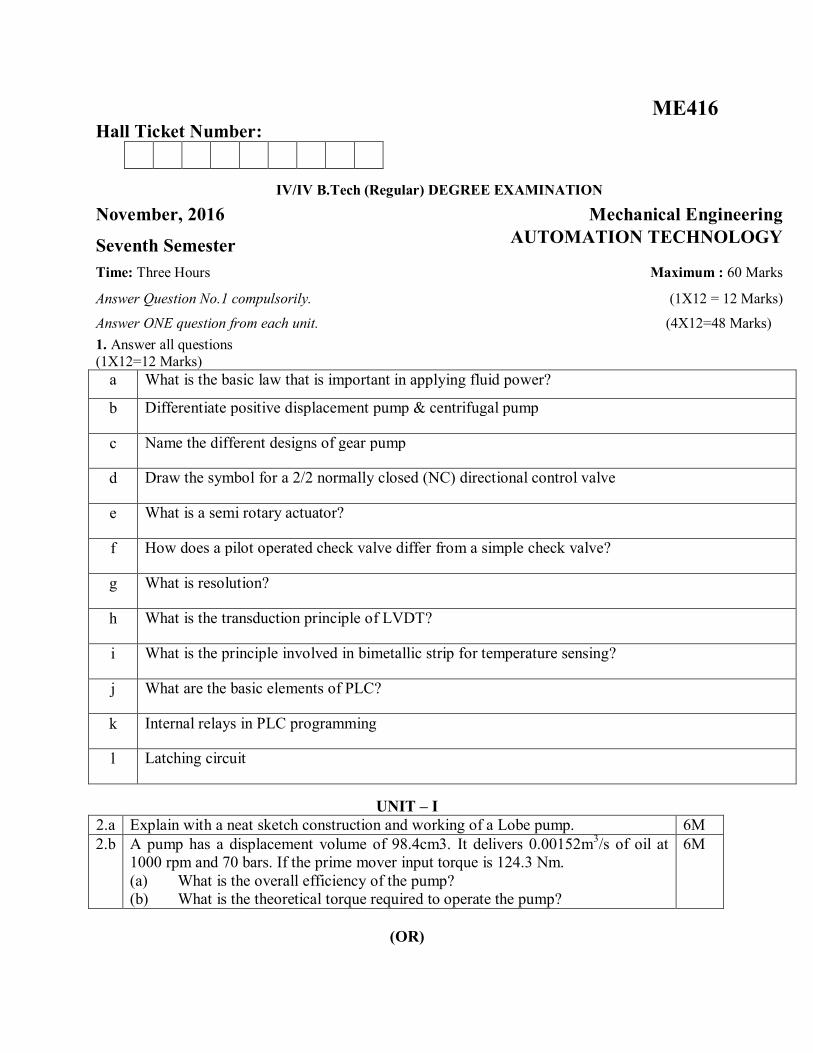
l Latching circuit
It is a circuit after being energized, maintains that state until another input is received.

UNIT – I
2.a Explain with a neat sketch construction and working of a Lobe pump. This pump operates in a fashion similar to the external gear pump. In this pump, both the lobes are driven externally so that they do not actually contact each other. Thus they are quieter than other types of gear pumps. Due to the smaller number of mating elements, the lobe pump output will have a somewhat greater amount of pulsation, although its volumetric displacement is generally greater than that for other types of gear pumps.
6M
2.b A pump has a displacement volume of 98.4cm3. It delivers 0.00152m3/s of oil at 1000 rpm and 70 bars. If the prime mover input torque is 124.3 Nm. (a) What is the overall efficiency of the pump? (b) What is the theoretical torque required to operate the pump?
We have, QA=0.00152 m3/s Pump speed, N= 1000 rpm=104.72 rad/s TA=124.3 Nm
p=70 bar Theoretical torque
푇 (푁.푚) =푉 (푚 ) × 푃(푃푎)
2휋=
98.4 × 10 × 70 × 102휋
= 109.63 푁푚
표푣푒푟푎푙푙 푒푓푓푖푐푖푒푛푐푦 =푎푐푡푢푎푙 푝표푤푒푟 푑푒푖푣푒푟푒푑 푏푦 푝푢푚푝푎푐푡푢푎푙 푝표푤푒푟 푑푒푙푖푣푒푟푒푑 푡표 푝푢푚푝
휂 =푝(푏푎푟)푄 (푚 푠⁄ )
푇 (푁푚) 푁 푟푎푑푠
=70 × 10 × 0.00152
124.3 × 104.72= 0.817 = 81.7 %
6M

(OR)
3.a With a block diagram explain the various stages of air treatment. Air in a pneumatic system must be clean and dry to reduce wear and extend maintenance periods. The air leaving the compressor can be hot and contain contaminants such as oil from the compressor, moisture and dirt particles. Thus after-coolers, dryers and filters are used to give contaminant-free air at the ambient temperature, with lubricators to add controlled lubricants to the air in order to lubricate pneumatic devices.
In general, this treatment falls into three distinct stages, shown in above figure. First, inlet filtering removes particles which can damage the air compressor. Next there is the need to dry the air to reduce humidity and lower the dew point. This is normally performed between the compressor and the receiver and is termed primary air treatment. The final treatment is performed local to the duties to be performed, and consists of further steps to remove moisture and dirt and the introduction of a fine oil mist to aid lubrication. This is secondary air treatment.
8M
3.b A compressed air tank has a volume of 0.5m3 and contains air at a gauge pressure of 1.96MPa and a temperature of 50oC. if the atmospheric pressure is 103kPa, determine the mass of air in the tank. The gas constant for air is 0.287kJ/kgK
From the general gas equation we write,
푝푉 = 푚푅푇
p= gage pressure (Pa) =1.96 MPa =1.96 x106 =1960 x 103 V= volume of tank (m3) = 0.5 m = mass of air (kg) = m R = Gas constant (J/kg.K) = 287 T = Absolute temperature (oK) = 50+273 = 323
푚 =(1960 + 103)10 × 0.5
287 × 323=
103150092701
= 11.12 푘푔
4M

UNIT – II
4.a With a neat sketch explain construction details of a typical double-acting cylinder. A double-acting cylinder is one powered by fluid for the movement of the piston in both the extend and return directions. With such a cylinder, two ports are used alternatively as supply and exhaust ports, so that pressure is used to give both the extend and return strokes. Thus, unlike the single- acting cylinder, no spring is required for the return stroke. Because of this, the double-acting cylinder is able to do work on both the extend and return strokes, the single-acting cylinder only being able to do work on the extend stroke. Below Figure shows the basic form of such a cylinder and the symbols. As shown in figure there is one piston rod, the area of the piston on which the pressure acts is different for the two sides of the piston.
For a piston of area A and a piston rod of cross-sectional area a (see figure above), if the pressure p is applied to the left-hand side of the piston and the right-hand side exhausted, then the force due to the pressure is pA.
On the return stroke, when the pressure is applied to the right-hand side, the force on the piston due to the pressure is p (A-a). If we have a mechanical efficiency η then the extend force is pAη and the return force p (A-a) η.
The extend stroke force is thus greater than the return force stroke.
8M

4.b Draw symbolic representation for various valve actuation methods.
4M
(OR)
5.a What is meant by synchronization of a cylinder motion? Name the various methods to achieve it. Explain any one method with a neat circuit. Figure shown below illustrates a common problem in which an unbalanced load is to be lifted by two cylinders. The right hand cylinder is subject to a large force F, the left-hand cylinder to a smaller force f. the right-hand piston requires a pressure of F/A to lift, while the left hand piston need f/A.
6M

When lift is called for on valve V1, the pressure rises to the lower pressure f/A, and only the left-hand piston moves. The unbalanced load results in faulty operation. In other words, cylinders hooked in parallel will not operate in synchronization. The cylinder synchronization can be achieved by the following methods:
1. By the use of flow divider valve 2. By linked hydraulic motors 3. By connecting the cylinders in series. [Explanation of any one of the above stated methods is sufficient. Write-
up for all three is given below.]
Flow divider valve The flow divider valve divides the inlet flow equally (to a few percent) between two outlet ports as shown in figure below. The spool moves to maintain equal pressure drops across orifices X and Y. and hence equal flow through them.
Cylinder synchronization by linked hydraulic motors The displacement of a hydraulic or pneumatic motor can be accurately specified, and this forms the basis for this type of synchronization. As shown in figure below, fluid for two cylinders passes through two mechanically coupled motors. The mechanical coupling ensures the two motors rotate at the same speed, and hence equal flow is passed into each cylinder.

Cylinder synchronization by connecting cylinders in series The two cylinders in the following figure are effectively in series with fluid from the annulus side of cylinder 1 going to the full bore side of cylinder 2. The cylinders are chosen, however, so that full bore area of cylinder 2 equals the annulus area of cylinder 1. Upon cylinder extension, fluid exits from cylinder 1 and causes cylinder 2 to extend. The two cylinders move at equal speed because of equal areas.
However, the main drawback of this arrangement is that cylinder 1 is subjected to a pressure (P1) of (F+f)/A. This is higher than would be required by two independent cylinders acting in parallel. The rotational speed of motors with equal displacement can similarly be synchronized by connecting them in series. Inlet pressure of the first motor is again, however, higher than needed to drive the two motors separately or in parallel.

5.b A double-acting cylinder is hooked up in the regenerative circuit. The relief valve setting is 105 bars. The piston area is 130 cm2 and the rod area is 65 cm2. If the pump flow is 0.0016 m3/s, find the cylinder speed and load-carrying capacity for the
(a) Extending stroke (b) Retracting stroke
We have; 퐴 = 130 푐푚 = 0.0130 푚
퐴 = 65 푐푚 = 0.0065 푚
(a) Extending stroke (left position of the valve): Regenerative extension stroke.
퐶푦푙푖푛푑푒푟 푠푝푒푒푑 =푄퐴
=0.00160.0065
= 0.25 푚/푠
퐿표푎푑 푐푎푟푟푦푖푛푔 푐푎푝푎푐푖푡푦 = 푝퐴 = 105 × 10 × 0.0065 = 68250 푁= 68.25 푘푁
(b) Retracting stroke (Right position of the valve): Retraction stroke
퐶푦푙푖푛푑푒푟 푠푝푒푒푑 =푄
퐴 − 퐴=
0.0016(0.0130 − 0.0065)
= 0.25 푚/푠
퐿표푎푑 푐푎푟푟푦푖푛푔 푐푎푝푎푐푖푡푦 = 푝(퐴 − 퐴 )
= 105 × 10 (0.0130 − 0.0065) = 68250 푁 = 68.25 푘푁
6M
UNIT – III
6.a Explain the principle and working of Incremental encoder for displacement & velocity measurement. The term encoder is used for a device that provides a digital output as a result of angular or linear displacement. An incremental encoder detects changes in angular or linear displacement from some datum position; an absolute encoder gives the actual angular or linear position.
6M
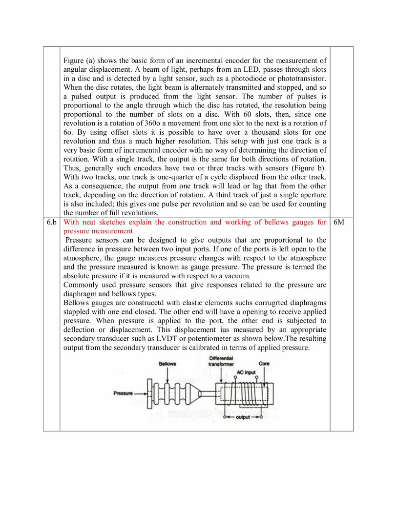
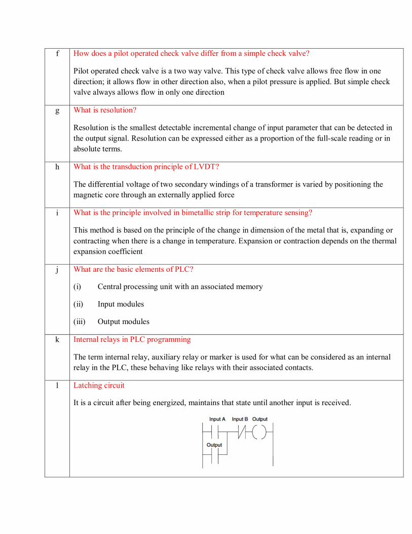
Figure (a) shows the basic form of an incremental encoder for the measurement of angular displacement. A beam of light, perhaps from an LED, passes through slots in a disc and is detected by a light sensor, such as a photodiode or phototransistor. When the disc rotates, the light beam is alternately transmitted and stopped, and so a pulsed output is produced from the light sensor. The number of pulses is proportional to the angle through which the disc has rotated, the resolution being proportional to the number of slots on a disc. With 60 slots, then, since one revolution is a rotation of 360o a movement from one slot to the next is a rotation of 6o. By using offset slots it is possible to have over a thousand slots for one revolution and thus a much higher resolution. This setup with just one track is a very basic form of incremental encoder with no way of determining the direction of rotation. With a single track, the output is the same for both directions of rotation. Thus, generally such encoders have two or three tracks with sensors (Figure b). With two tracks, one track is one-quarter of a cycle displaced from the other track. As a consequence, the output from one track will lead or lag that from the other track, depending on the direction of rotation. A third track of just a single aperture is also included; this gives one pulse per revolution and so can be used for counting the number of full revolutions.
6.b With neat sketches explain the construction and working of bellows gauges for pressure measurement. Pressure sensors can be designed to give outputs that are proportional to the difference in pressure between two input ports. If one of the ports is left open to the atmosphere, the gauge measures pressure changes with respect to the atmosphere and the pressure measured is known as gauge pressure. The pressure is termed the absolute pressure if it is measured with respect to a vacuum. Commonly used pressure sensors that give responses related to the pressure are diaphragm and bellows types. Bellows gauges are construcetd with elastic elements suchs corrugrted diaphragms stappled with one end closed. The other end will have a opening to receive applied pressure. When pressure is applied to the port, the other end is subjected to deflection or displacement. This displacement ius measured by an appropriate secondary transducer such as LVDT or potentiometer as shown below.The resulting output from the secondary transducer is calibrated in terms of applied pressure.
6M

(OR) 7.a With neat sketches explain the principle, operation and working of RTD and
Thermocouple for temperature measurement. Resistance thermometers, which are alternatively known as resistance temperature detectors rely on the principle that the resistance of a metal varies with temperature according to the relationship:
푅 = 푅 (1 + 푎 푇 + 푎 푇 + 푎 푇 + ⋯… . +푎 푇 )
This equation is non-linear and so is inconvenient for measurement purposes. The equation becomes linear if all the terms in a2T2 and higher powers of T are negligible such that the resistance and temperature are related according to:
푅 ≈ 푅 (1 + 푎푇)
Where, R is the resistance at a temperature ToC, R0 the resistance at 0°C and ‘a’ a constant for the metal, termed the temperature coefficient of resistance.
8M

Resistance temperature detectors (RTDs) are simple resistive elements in the form of coils of metal wire, e.g. platinum, nickel or nickel-copper alloys. The variation of resistance with temperature for typical metals is shown in figure.
Platinum is the most widely used. Thin-film platinum elements are often made by depositing the metal on a suitable substrate, wire-wound elements involving a platinum wire held by a high-temperature glass adhesive inside a ceramic tube.
Platinum detectors have high linearity, good repeatability, high long term stability, can give an accuracy of ±0.5% or better, a range of about -200oC to +850oC, can be used in a wide range of environments without deterioration, but are more expensive than the other metals. They are, however, very widely used. Nickel and copper alloys are cheaper but have less stability, are more prone to interaction with the environment and cannot be used over such large temperature ranges. They tend to have response times of the order of 0.5 to 5s or more.
Thermocouple If two different metals are joined together, a potential difference occurs across the junction. The potential difference depends on the metals used and the temperature of the junction. A thermocouple is a complete circuit involving two such junctions

If both junctions are at the same temperature there is no net e.m.f. if, however, there is a difference in temperature between the two junctions, there is an e.m.f. The value of this e.m.f, E depends on the two metals concerned and the temperatures t of both junctions. Usually one junction is held at 0oC and then to a reasonable extent, the following relationship holds:
퐸 = 푎푡 + 푏푡
Where, a and b are constants for the metals concerned. Figure illustrates how the e.m.f varies with temperature for a number of commonly used pairs of metals.
Commonly used thermocouples are shown in Table below, with the temperature ranges over which they are generally used and typical sensitivities.

A thermocouple circuit can have other metals in the circuit and they will
have no effect on the thermoelectric e.m.f provided all their junctions are at the same temperature. This is known as the law of intermediate metals.
A thermocouple can be used with the reference junction at a temperature other than 0oC. The standard tables, however, assume a 0oC junction and hence a correction has to be applied before the tables can be used. The correction is applied using what is known as the law of intermediate temperatures. This is given by the following expression as:
퐸 , = 퐸 , + 퐸 , Where, ETh,T0 refers to e.m.f, E with measuring junction at temperature Th ,when the cold junction is at 0oC. ETh, Tr refers to e.m.f, E with measuring junction at temperature Th, when the cold junction is at reference temperature Tr (other than 0oC) ETr, T0 refers to e.m.f, E with measuring junction at temperature Tr, when the cold junction is at 0oC.
7.b A 12-bit binary absolute encoder is outputting the number 101100010111.
(i) What is the resolution of the encoder, and (ii) what is the range of angles indicated by its output?
(a) A 12-bit encoder will output 212 binary numbers for one revolution. Therefore,
the resolution is 360o/212 = 0.087891o. (b) Converting the binary number to decimal, we have 101100010112 = 283910. The
indicated angle is between 2839 x 0.087891o = 249.52o and 249.52o + 0.087891o = 249.60o.
4M

UNIT – IV 8.a With a neat sketch explain the basic architecture of a PLC
The above Figure shows the basic internal architecture of a PLC. It consists of a central processing unit (CPU) containing the system microprocessor, memory, and input/output circuitry. The CPU controls and processes all the operations within the PLC. It is supplied with a clock that has a frequency of typically between 1 and 8 MHz. This frequency determines the operating speed of the PLC and provides the timing and synchronization for all elements in the system. The information within the PLC is carried by means of digital signals. The internal paths along which digital signals flow are called buses. In the physical sense, a bus is just a number of conductors along which electrical signals can flow. It might be tracks on a printed circuit board or wires in a ribbon cable. The CPU uses the data bus for sending data between the constituent elements, the address bus to send the addresses of locations for accessing stored data, and the control bus for signals relating to internal control actions. The system bus is used for communications between the input/output ports and the input/output unit.
8M

8.b Explain the input/output processing cycle of a PLC A PLC is continuously running through its program and updating it as a result of the input signals. Each such loop is termed a cycle. There are two methods that can be used for input/output processing; continuous updating and mass input/output copying.
Continuous updating Continuous updating involves the CPU scanning the input channels as they occur in the program instructions. Each input point is examined individually and its effect on the program determined. There will be a built-in delay; typically about 3 ms, when each input is examined in order to ensure that only valid input signals are read by the microprocessor. This delay enables the microprocessor to avoid counting an input signal twice or more frequently, if there is a contact bounce at a switch. A number of inputs may have to be scanned, each with a 3 ms delay, before the program has the instruction for a logic operation to be executed and an output to occur. The outputs are latched so that they retain their status until the next updating.
Mass input/output copying Because there is time spent interrogating each input in turn with continuous updating, the time taken to examine several hundred input/output points can become comparatively long. To allow more rapid execution of a program, a specific area of RAM is used as a buffer store between the control logic and the input/output unit. Each input/output has an address in this memory. At the start of each program cycle the CPU scans all the inputs and copies their status into the input/output addresses in RAM. As the program is executed, the stored input data is read, as required, from RAM and the logic operations are carried out. The resulting output signals are stored in the reserved input/output section of RAM. At the end of each program cycle all the outputs are transferred from RAM to the appropriate output channels. The outputs then retain their status until the next updating. This method of operation is termed mass I/O copying. This is as shown in below figure.
4M
(OR)

9.a Differentiate Timers and counters in PLC programming. Timers In many control tasks there is a need to control time. For example, a motor or a pump might need to be controlled to operate for a particular interval of time or perhaps be switched on after some time interval. PLCs thus have timers as built-in devices. Timers count seconds or fractions of seconds using the internal CPU clock. PLC manufacturers differ on how timers should be programmed and hence how they can be considered. A common approach is to consider timers to behave like relays with coils that when energized; result in the closure or opening of contacts after some preset time. The timer is thus treated as an output for a rung, with control being exercised over pairs of contacts elsewhere (Figure (a) shown below). Some treat a timer as a delay block that when inserted in a rung, delays signals in that rung from reaching the output (Figure (b) shown below).
On-delay timers (TON) come on after a particular time delay (Figure a shown below). Thus as the input goes from 0 to 1, the elapsed time starts to increase, and when it reaches the time specified by the input PT, the output goes to 1. An off-delay timer (TOF) is on for a fixed period of time before turning off (Figure b shown below). The timer starts when the input signal changes from 1 to 0.
6M

Counters Counters are provided as built-in elements in PLCs and allow the number of occurrences of input signals to be counted. Some uses might include where items have to be counted as they pass along a conveyor belt, the number of revolutions of a shaft, or perhaps the number of people passing through a door. A counter is set to some preset number value and, when this value of input pulses has been received, it will operate its contacts. Normally open contacts would be closed, normally closed contacts opened. There are two basic types of counter: down-counters and up-counters. Down-counters count down from the preset value to zero, that is, events are subtracted from the set value. When the counter reaches the zero value, its contacts change state. Most PLCs offer down-counting. Up-counters count from zero up to the preset value, that is, events are added until the number reaches the preset value. When the counter reaches the set value, its contacts change state. Some PLCs offer the facility for both down- and up-counting.
9.b Draw the ladder diagram for the following: (i) NAND gate
(ii) OR gate
(iii) NOR gate
6M