it’s not over yet - bicsi - advancing the information … · 2013-01-10 · it’s not over yet...
TRANSCRIPT

It’s Not Over YetHigher Speed Ethernet Over Copper Twisted Pair
Stephen SkiestPanduit CorporationPanduit Corporation

History of BASE-T LANyLocal Area Networks over Copper Twisted Pair Cabling
Name Date Rate Standard Year Distance Cabling Type Cabling Bandwidth
10BASE-T 10 Mbps 802.3i 1990 100 m Category 3 3 MHz10BASE T 10 Mbps 802.3i 1990 100 m Category 32 pairs
3 MHz
100BASE-T 100 Mbps 802.3u 1995 100 m Category 5 2 pairs
100 MHz
1000BASE-T 1 Gbps 802.3ab 1999 100 m Category 5e4 pairs
100 MHz
10GBASE-T 10 Gbps 802.3an 2006 100 m Category 6A 500 MHzp g y4 pairs
Next Generation?

History of BASE-T LANyLocal Area Networks over Copper Twisted Pair Cabling
Name Date Rate Standard Year Distance Cabling Type Cabling Bandwidth
10BASE-T 10 Mbps 802.3i 1990 100 m Category 3 3 MHz10BASE T 10 Mbps 802.3i 1990 100 m Category 32 pairs
3 MHz
100BASE-T 100 Mbps 802.3u 1995 100 m Category 5 2 pairs
100 MHz
1000BASE-T 1 Gbps 802.3ab 1999 100 m Category 5e4 pairs
100 MHz
10GBASE-T 10 Gbps 802.3an 2006 100 m Category 6A 500 MHzp g y4 pairs
40GBASE-T 40 Gbps TBD TBD < 50 m Category 84 pairs
> 1000 MHz

Forecast for Server Interconnect
Source: July 2012 IEEE PlenarySource: July 2012 IEEE Plenaryy yy y

40G/100G Ethernet Standard
• IEEE 802.3ba was ratified June 2010• 8 PMDs are included• Short reach copper cable twin axial assembly• Short reach copper cable twin-axial assembly
was included for top of rack• Traditional Structured Twisted pair cabling was
not included• Multimode requires MPO/ribbon fiber
interconnect

40/100G 802.3ba Ethernet Options/ pReach 1m
Backplane7m copper cable
100m OM3/150m OM4
10km SMF 40km SMFp pp
assembly40 Gigabit Ethernet
PMD Name 40GBASE-KR4 40GBASE-CR4 40GBASE-SR4 40GBASE-LR4
Signaling 4 x 10Gbps 4 x 10Gbps 4 x 10Gbps 4 x 10GbpsMedia Backplane Twin-ax Parallel MMF Duplex SMFM d l QSFP QSFP CFPModule QSFP QSFP CFP
100 Gigabit EthernetPMD Name 100GBASE-CR10 100GBASE-SR10 100GBASE-LR4 100GBASE-ER4
Signaling 10 x 10Gbps 10 x 10Gbps 4 x 25Gbps 4 x 25GbpsMedia Twin-ax Parallel MMF Duplex SMF Duplex SMFModule CXP CFP or CXP CFP CFPModule CXP CFP or CXP CFP CFP

Extensive Technical Study on 40GBASE-T Feasibility
Source: IEEE NGBASE-T CFI July 2012
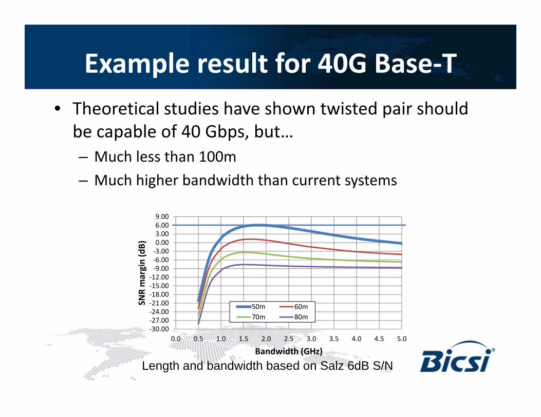
Example result for 40G Base-Tp• Theoretical studies have shown twisted pair should
be capable of 40 Gbps butbe capable of 40 Gbps, but…– Much less than 100m– Much higher bandwidth than current systemsMuch higher bandwidth than current systems
3 006.009.00
-15.00-12.00
-9.00-6.00-3.000.003.00
mar
gin
(dB)
-30.00-27.00-24.00-21.00-18.0015.00
0 0 0 5 1 0 1 5 2 0 2 5 3 0 3 5 4 0 4 5 5 0
SNR
50m 60m70m 80m
0.0 0.5 1.0 1.5 2.0 2.5 3.0 3.5 4.0 4.5 5.0
Bandwidth (GHz)
Length and bandwidth based on Salz 6dB S/N

Data Center Application Spacespp pTop of Rack Switching
3m max patching length 5 or 73m max patching length, 5 or 7 m to cover multiple cabinets, this is covered by 40GBASE-CR4
End of Row SwitchingEnd of Row SwitchingEx, 18 cabinet row with 16 server cab, 1m across each cab plus1m up & down = 19 m link plus 3m patch = 22m longest channel

Typical Data Center Layout TodayUses dedicated Network RowsUses dedicated Network Rows
Longest link = 55m (60m channel)
NetworkRow
NetworkRow
Server Rows
Although 100m availableAlthough 100m available, Typically use 50 to 60 m as the longest channels

NGBASE-T Application Spacepp p• Longer than 40GBASE-CR4 twin-axial cables of 7m
d ff i h f d f i hb i• Need cost effective reach for end of row, neighboring row, network row, switching applications

Space Benefits of NGBASE-T (w/RJ45 or similar footprint)(w/RJ45 or similar footprint)
RJ45 footprint 40G QSFP+ C F t i tCage Footprint
Top View (1x4)1.9”
Top View (2x4)0.8”
• RJ45 vs. QSFP (CR4)• 48 ports in 1RU vs. 36
3.5”
1.9”
2.5”
1.1” port in 1 RU• Also 1/3 as much board
space real estatespace real estate.
3.5”
Front View (1x4)2.5” 1.0”
Front View (2x4)
1.0”
NGBASE-T Study Group y p• Equipment, PHY, and Cabling vendors met at
h IEEE i i J l 2012 i S Dithe IEEE meeting in July 2012 in San Diego• CFI was approved and a Next Generation
Base-T study group formed – 61 individual supporters from 40 companies
• Study group to clarify feasibility with objective to form a task force which will create the standard

NGBASE-T Objectives adopted Sept 25, 2012
• Support full duplex operation only• Preserve the 802 3 / Ethernet frame format utilizing the 802 3 MAC• Preserve the 802.3 / Ethernet frame format utilizing the 802.3 MAC• Preserve minimum and maximum Frame Size of current 802.3
standard• Support a BER > 10-12 at the MAC/PLS service interface• Support Auto-Negotiation (Clause 28)• Support optional Energy Efficient Ethernet• Support local area networks using point-to-point links over structured
cabling topologies including directly connected link segmentscabling topologies, including directly connected link segments• Do not preclude meeting FCC and CISPR EMC requirements• Support a data rate of 40 Gb/s at the MAC/PLS Service InterfaceSupport a data rate of 40 Gb/s at the MAC/PLS Service Interface

NGBASE-T Limitation: Power• Very preliminary IEEE studies show 22m reach
l d ’ 10GBASE T /equal today’s 10GBASE-T on power/port• 46m equal 10GBASE-T power/bit• Don’t expect > 50m is feasible and 20-30m is
more likelyy

Power Penalty for High Data Rate Base-TNot cost as much as Heat DissipationNot cost as much as Heat Dissipation
• Average cost of commercial electricity in US: $0.105/kWh• If 24/7 operation: 8.76 k hrs x $0.105/kWh = $0.92 per 1W
• Example: 10GBASE-T adds 2.5W per port (5W)$ / /– Only $4.6/yr per link added Opex ,if 24/7 operation, not very high
• Issue is more about equipment design & ability to cool a high density switch or integrate electronics on a server y gmotherboard
• Current 10GBASE-T technology (power) is the max. b h k l l f i t th l d ibenchmark level for equipment thermal design

What Link Lengths Needed in Data Centers: Panduit Cabling Reach StudyCenters: Panduit Cabling Reach Study
• Pre-terminated Data Center deployments: 0.25mServer Cabinet
2011-2102– Cat6A only: intent to run 10Gig
U 10G t i t d i d t d i f2 m
– Use 10G twisted pair data as user desire for 40G
• Compiled link lengths
2.5m Patch onServer endCompiled link lengths
• Add in estimates for patching: 4m– 2.5 m on server end
0.25mSwitch Cabinet
0.25m2.5 m on server end– 1.5 m on switch end
• Note min. channel: 5m
1 m
0.25m
1.5m Patch onSwitch end
– 3m link + 2x 1m patch
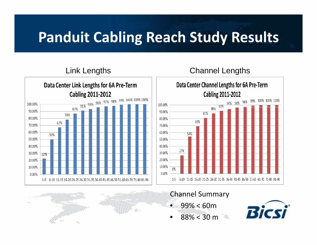
Panduit Cabling Reach Study Results
Link Lengths Channel Lengths
Channel Summary• 99% < 60m• 88% < 30 m

Typical Data Center Layout Today
Longest link = 55m (60m channel)
Network N t kNetworkRow
NetworkRow
Server Rows

With a Shorter Reach of 30 meters
Longest link = 25m (30m channel)
NetworkNetworkRowsServer Rows Server Rows
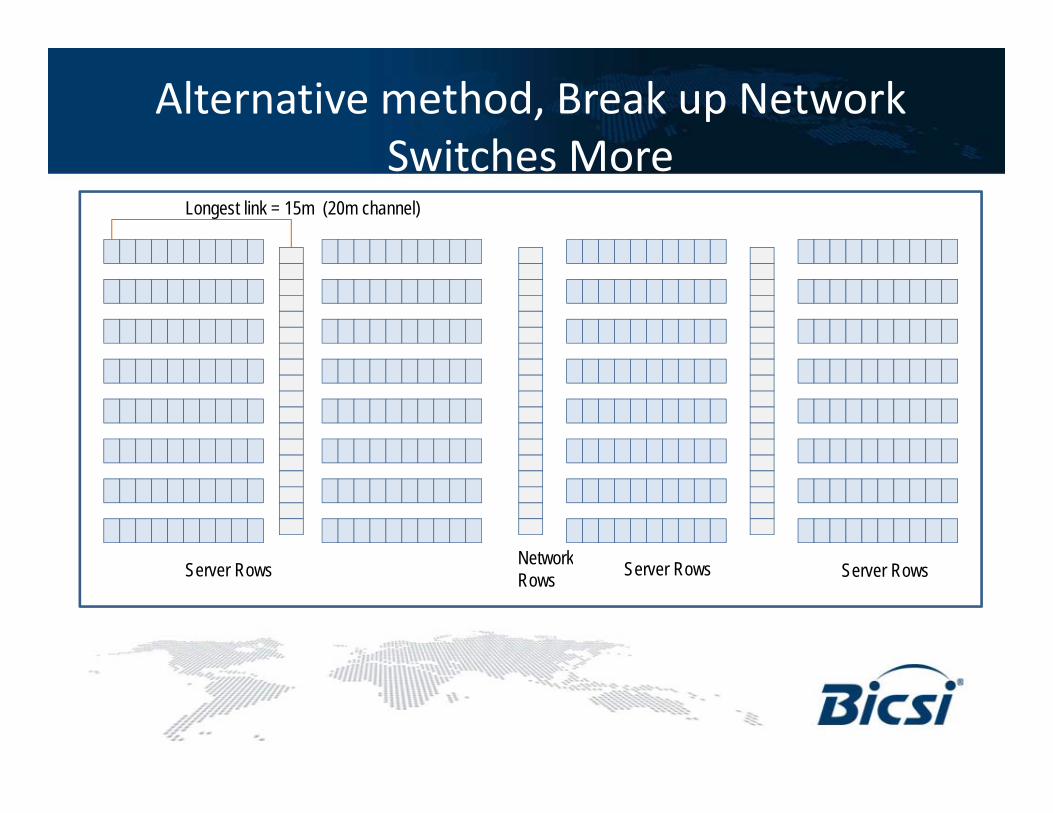
Alternative method, Break up Network Switches MoreSwitches More
Longest link = 15m (20m channel)
NetworkNetworkRowsServer Rows Server RowsServer Rows

Cabling Study Groupsg y p• TIA
– New Category 8 cabling with enhanced RJ45 out to 2 GHz
• ISO– Extending Cat7A to 2 GHz with IEC 60603-7-71
(GG45) or 61076-3-104 (Tera)– Non-RJ45 interfaces. IEC60603-7-71 accepts RJ45
lplug
• IEEE still needs to define BW and interface

TIA Category 8g y• Category 8 being developed by theTR42.7 Copper Cabling Systems
Subcommittee in support of 40GBASE TSubcommittee in support of 40GBASE-T• Cat 8 has bandwidth specifications up to 2GHz ensure it has enough BW to
bandwidth for IEEE 40GBASE-T applicationF ll b k d tibl ith ll ANSI/TIA 568 C 2 i d t d d• Fully backwards compatible with all ANSI/TIA-568-C.2 recognized standards
– New draft would be published as ANSI/TIA-568-C.2-1

Category 8 Specificationsg y p
• Designed around shielded cabling and h d RJ45 ti itenhanced RJ45 connectivity
– S/FTP, U/FTP, or F/UTP would be acceptable– UTP would not be acceptable due to alien
crosstalk requirementscrosstalk requirements– Shielded components would be required– RJ45 interfaces mean no hybrid cords
• Specification has detailed requirements for p qalmost all parameters, but will not be finalized until the IEEE finalizes their needs
• Most internal channel parameters are an t i f th C t 6A textension of the Category 6A parameters up
to 2GHz

TIA Preliminary Cat 8 Channel
• 2 connector channel only• 40 meter link• 50 meter channel (with 20% de-rated patch cords)

Preliminary Requirementsy qCategory 8 Preliminary Specifications
For 50 meter Channel
60
70
For 50 meter Channel
40
50
dB Insertion Loss
20
30
d Insertion Loss
NEXT
Return Loss
0
10
0 200 400 600 800 1000 1200 1400 1600 1800 2000F (MH )Frequency (MHz)

Types of Shielded Cablingyp g
F/UTP(also known as FTP)Overall foil shield
U/FTPU/FTPIndividual foils around each pair
S/FTP (also S-STP or PiMF)Individual foils around each pair and an overall braidan overall braid
SF/UTPO ll f il d ll b idOverall foil and overall braid

Future Proofing?g
Can you future proof to 40Gig today? • Risky for 40G since defined BW is not finalized and
cannot test out to 2 GHz yet• And max allowable reach is not defined

Summaryy• Industry is formally working on a standard for
40Gi i d i d f DC40Gig over copper twisted pair targeted for DC• Very early stages, but will be:
– Less than 50m, < 30m likely– More than 1000 MHz BW, > 1500 MHz likely– Shielded cabling will be required
• Standard not likely until 2015+Standard not likely until 2015