itp energy intensive proceeses: technology roadmap for energy reduction ... · pdf...
TRANSCRIPT


Preface Recognizing the importance of energy efficiency to the nation and industry, the U.S. Department of Energy’s (DOE) Industrial Technologies Program (ITP), in collaboration with the United States Council for Automotive Research LLC (USCAR), hosted a technology roadmap workshop in Troy, Michigan on May 20-21, 2008. The purpose of the workshop was to explore opportunities for energy reduction, discuss the challenges and barriers that might need to be overcome, and identify priorities for future R&D.
The results of the workshop are presented in this Technology Roadmap for Energy Reduction in Automotive Manufacturing. The roadmap will be used by public and private organizations to help guide decision-making for future research, development, and demonstration projects. The priorities presented here are not all-inclusive, but represent a major step toward identifying ways to potentially reduce energy intensity in automotive manufacturing and the associated supply chain.

Table of Contents Executive Summary ..............................................................................................ii
1 Introduction.......................................................................................................1
2 Overview of the Automotive Supply Chain......................................................3
3 Opportunities for Energy Reduction in Auto Manufacturing ...........................5
4 Body in White and Components .......................................................................7
5 Automotive Paint .............................................................................................17
6 Powertrain and Chassis Components ................................................................27
7 Final Assembly .................................................................................................37
8 Plant Infrastructure ...........................................................................................45
9 Crosscutting Opportunities for Saving Energy .................................................53
10 Moving Forward .............................................................................................59
Appendix A: List of Contributors ........................................................................A-1
Appendix B: Comprehensive List of R&D Needs...............................................B-1
Appendix C: Acronyms .......................................................................................C-1
i

Executive Summary Faced with decreasing supplies and increasing costs of energy resources, reducing energy use has become an important challenge for the United States. For U.S. automotive manufacturers, energy purchases impact production costs and the industry’s competitiveness. Transportation manufacturing, which includes automotive, is now the 8th
largest industrial energy consumer in the U.S. Between 2002 and 2005, energy expenditures in this sector increased overall by 20%. Electricity purchases increased by about 20%; purchases of fuels (mostly natural gas and diesel) increased by a staggering 50%. [ASM 2005]
Technology Roadmap Workshop for While today’s automotive manufacturing facilities are modern and Energy Reduction in Automotive relatively efficient, significant opportunities remain to reduce energy Manufacturing, May 20-21, 2008, Troy, demand through better energy management, technology innovation, Michigan and research and development (R&D). The benefits could be great –
conservation of energy, less impact on the environment, and an � Included representatives from the U.S. enhanced competitive position for the U.S. automotive industry. DOE, USCAR, major automotive
suppliers, utilities, and national laboratories To address the energy challenge, the U.S. Department of Energy’s
(DOE) Industrial Technologies Program (ITP) and the U.S. Council � Identified opportunities for energy for Automotive Research (USCAR) are exploring ways to reduce the
reduction, challenges and barriers to energy intensity of automotive manufacturing. Identifying the pre-overcome, and priority R&D areas competitive, high-risk R&D needed to accelerate the use of more
energy efficient manufacturing processes is critical to their future � Will help guide decision making for efforts.future R&D to reduce energy intensity
in automotive manufacturing This Technology Roadmap for Energy Reduction in Automotive Manufacturing will help provide direction and focus to both public
and private decision-makers as they pursue R&D that will help reduce energy consumption and improve energy efficiency in automotive manufacturing.
Energy and the U.S. Automotive Enterprise The automotive enterprise encompasses much more than the manufacture of vehicles. As Exhibit E-1 illustrates, it is a complex supply chain that includes producing raw materials such as steel, aluminum, plastics, and glass; forming and fabricating parts, components, and subsystems; assembling hundreds of these elements to make the vehicles; and, distributing and selling the vehicles. Over 2 million people are employed in the U.S. in automobile manufacturing or retail trade, according the U.S. Bureau of Labor Statistics [BLS 2009]. The automotive enterprise is a major player in the U.S. economy, with over 20,000 suppliers and 50,000 facilities contributing to U.S. automotive shipments valued at over $500 billion in 2006 [BEA 2008]. NADA estimates that dealers generate in excess of $20 billion in annual sales tax revenue which contributes to the budgets for state and local governments across the country [NADA 2008].
The energy use associated with the U.S. automotive enterprise has been roughly estimated at over 800 trillion Btus (British thermal units) per year. Note that the energy consumed by the major suppliers serving the automotive manufacturing is not included in this figure, nor is the energy associated with transport and delivery of vehicles to the market. If all relevant energy use were included, the energy attributed to the automotive enterprise would be significantly higher.
There are many opportunities to reduce energy use where vehicles are manufactured, as well as in supplier operations. Among these are developing more efficient technologies and materials, implementing best energy management practices, and increasing use of energy resources such as waste heat. There are also opportunities to use alternative energy resources such as hydrogen, biomass, solar, geothermal, and wind to provide power and heat for manufacturing operations.
ii

Exhibit E-1. The Automotive Enterprise
Exhibit E-2 illustrates the magnitude of the opportunities – the automotive enterprise consumes about 800 trillion Btus annually. Using a conservative approach, if estimated energy use could be reduced by just 10%, the energy savings would be 80 trillion Btus per year, the equivalent of about 650 million gallons of gasoline or the energy needed to heat about 2 million U.S. households.
Increasing energy efficiency also provides ancillary benefits, such as greater productivity, fewer rejected parts and wastes, and reduced emissions to the environment, as well as lower energy expenditures. The end results will benefit both the automotive industry and the nation.
Improvements made in automotive manufacturing could also be used in industries where similar processes or equipment are employed, such as the manufacture of farm equipment, industrial machinery, fabricated metals, heavy trucks, rail cars, ships, and aircraft. As Exhibit E-2 illustrates, these industries use nearly 700 trillion Btus of energy annually.
iii

Estimated Automotive Enterprise Energy Use >800 TBtu
*Energy values are preliminary based on published estimates DOC/Annual Survey of Manufactures data for fuels and electricity. **Could be internal to plant or outsourced. TBtu = Trillion Btus
Energy use in industries with similar processes:Transport Mfg ~100 Tbtu Heavy Machinery ~180 Tbtu Fabricated Metals ~390 TBtu
Body Non-Structure
Steering
Front Suspension
Rear Suspension
Brakes
Electrical
Fuel and Exhaust
Bumpers
Wheels and Tires
Air Conditioning
Windows
Paint
Exhibit E-2. Estimated Distribution of Energy Use in the Automotive Enterprise
Materials: ~500 Tbtu*
Aluminum, Magnesium,
Titanium
Iron & Steel
Zinc, Lead, Copper
Ferrous & Non-Ferrous Castings
Textiles
Plastics, Rubber
RAW MATERIALS
PROCESSED MATERIALS
Glass
~300 Tbtu*
AUTOMOTIVE OEM
PROCESSES
Die Making** Casting** Stamping
Body Shop Painting
Power Train Assembly
Component and Subsystem Suppliers
Priorities for Research and Development Roadmap priorities for R&D are grouped in the five key areas shown below. These priorities encompass challenges that occur within the manufacturing production facility, as well as those in supplier facilities where subsystems, modules, and components are manufactured. Exhibit E-3 illustrates the priority topics for each of these areas.
� Body in White (BIW) and Closures – the assembly of the vehicle structure, and the sheet metal closures (doors, hoods, and deck lids)
� Automotive Paint –the interior and exterior body structure from BIW is painted using a multi-layer paint process
� Powertrain and Chassis Components –the engine, transmission, driveshaft, differential, and suspension are integrated with the chassis (frame) and components
� Final Assembly – the body, powertrain, and chassis of the vehicle are integrated with all the final parts, such as seats, dashboard assemblies, interior trim panels, wheels, windshields, and many others
� Plant Infrastructure – facilities and energy systems that are needed to keep automotive manufacturing operations running and employees in a comfortable and safe environment, such as boilers, power systems, heating/cooling, and others
The roadmap also includes a number of crosscutting topics with potential application across more than one area of manufacturing. Among these are waste heat recovery, wireless systems, benchmarking and modeling of energy use in production facilities, and manufacturing challenges for high volume production of next generation vehicles.
iv

‐
Exhibit E-3
Priority R&D Topics for Reducing Energy Use in Automotive Manufacturing
Body In White
Automotive Paint
Powertrain & Chassis
Final Assembly
Energy-efficient joining technologies for high-
volume parts using similar or dissimilar metals, polymers &
composites
Alternative technologies &
processes to cure and dry paint in mass production paint
shops
Novel, energy-efficient heat treating
technologies to enable 50% energy reduction
over conventional processes
Advanced material handling & logistics
technologies (wireless sensors, advanced
batteries, frictionless conveyors)
Alternative motor systems to replace
compressed air actuators (CNC machines, stamping
counter balances, conveyor take-ups)
Plant Infra structure
New materials for high strength, high
formability, lightweight parts
and body structures
Non-spray paint processes with
today’s performance & elimination of large air volume
conditioning
Energy-efficient die-cast & semi-
permanent mold casting, and novel
sand-casting for high volume cylinder heads
Low friction fasteners that
minimize energy use while
achieving desired clamp loads
Advanced monitoring/control of
energy/emissions, with plant-wide data
collection & feedback systems
Processes to reduce scrap and
increase materials
utilization in body structures
Elimination/ reduction of
energy, water & chemical
requirements in paint pretreatment
Optimized machining via control/logic strategies, dry machining, machine structure design, power
storage, & preheat reduction
Energy-efficient tooling & equipment for
assembly (energy regeneration, minimized
idle state energy, less compressed air)
Reliable wireless industrial networks to
monitor/control energy & building systems with
new frequency spectrums
Advanced auto body manufacturing – energy efficient
processes, tools, dies and molds, reduction
of process steps
Spray coating materials that adapt
to varying spray booth air environments – relative humidity
adaptive paint
Manufacturing of powertrain &
chassis components with
new lightweight net shape materials
Alternative energy (solar, biogas, wind,
hydrogen, advanced batteries) for lighting & HVAC
in assembly
Life cycle management of
facilities and process equipment
to reduce over-sizing & energy losses
Crosscutting R&D Topics
Energy Recovery Assessing /Modeling Energy Next Generation Vehicles •Casting or heat treating of metals •Processes and sub-processes •Energy efficient high volume
•Bulk materials manufacturing •Building envelope manufacturing processes •Plastic scrap incineration •Plant-wide logistics systems •High volume energy storage
•Cooling fluids •Energy embedded in subsystems, production (batteries, ultra •Low temperature waste heat modules, components capacitors, others)
•Thermal regeneration •Raw material energy •Power electronics & wiring •Combined heat and power •Life cycle energy •Electric motors manufacture
v

Moving Forward Creation of this technology roadmap represented a focused effort to understand the opportunities for reducing energy consumption in automotive manufacturing and the associated supply chain. Clearly, the opportunities are many and span every aspect of the industry.
It is hoped that this roadmap will provide direction and a basis for future decision making and investments in R&D to enable energy reduction in automotive manufacturing. While it does not cover all areas in depth, it does bring out some important ideas. It is notable that the concepts presented here represent a wide range of technologies and opportunities – from the very near-term to revolutionary changes that could be achieved in the future. One thing is certain – the automotive enterprise will continue to adapt and improve to meet approaching energy challenges.
Looking forward, this roadmap illuminates some of the key opportunities for energy efficiency in the automotive enterprise that can potentially be achieved through R&D and other actions. Developing these energy efficiency gains may require long-term, high-risk research, and the foundation of new public-private collaborations involving academia, national labs, government, OEMs, and suppliers. As future R&D projects are initiated, the automotive industry and the nation can begin to reap the benefits that accrue from reducing the use of our precious energy resources.
This roadmap is dynamic – it will continue to change and be refined and expanded as more industry participants become involved and as technology breakthroughs emerge.
Sources ASM 2005. Annual Survey of Manufacturers 2005. U.S. Department of Commerce.
BEA 2008. Gross Domestic Product by Industry, 1998-2007. Bureau of Economic Analysis. U.S. Department of Commerce.
BLS 2009. Automotive Industry: Employment, Earnings, and Hours. U.S. Department of Labor, Bureau of Labor Statistics (http://www.bls.gov/iag/tgs/iagauto.htm)
NADA 2008. National Automobile Dealers Association. NADA Sales Data 2008. (http://www.nada.org/Publications/NADADATA/2008/)
vi

1.0 Introduction
Energy efficiency is an important priority for the United States. As it relates to automotive manufacturing, energy purchases have a major impact on production costs and ultimately the industry’s competitiveness. Transportation manufacturing, (which includes automotive), is now the 8th largest industrial energy consumer in the United States. Between 2002 and 2005, energy expenditures increased 20% in the transportation sector, purchases of electricity went up nearly 10%, and the cost of fuels increased nearly 50%.1 The energy embodied in the large and complex supply chain needed to produce a vehicle – from production of raw materials to final assembly – is substantial.
Conserving energy through more efficient processes, technologies, and products is the fastest way to lower energy use in automotive manufacturing in the near-term. While many manufacturing facilities today are modernized and relatively efficient, significant opportunities remain to reduce energy demand via innovation and research and development (R&D). The benefits: greater conservation of energy resources, improved productivity, reduced impact on the environment, and an enhanced competitive position for U.S. industry.
To address this energy efficiency challenge, the U.S. Department of Energy’s (DOE) Industrial Technologies Program (ITP) and the United States Council for Automotive Research LLC (USCAR) are exploring ways to reduce the energy intensity of automotive manufacturing. At the core is identifying the pre-competitive, high-risk R&D needed to accelerate the use of more energy efficient production processes for automotive manufacturing.
To gain insights on reducing energy intensity in automotive manufacturing, a technology roadmap workshop was held at Michigan State Management Education Center in Troy, Michigan on May 20-21, 2008. This meeting brought together representatives from DOE, USCAR, major or integral supplier to the automotive industry (referred to as Allied and Tier suppliers), utilities, and national laboratories – all with expertise in the automotive industry. The purpose of the workshop was to explore opportunities for energy reduction, discuss the challenges and barriers that might need to be overcome, and identify priorities for future R&D. The workshop covered five topics relative to major operations in automotive manufacturing, as well as crosscutting issues such as waste minimization, materials, and recycling (see Exhibit 1.1).
The results of the workshop, along with public information from other sources, provide a foundation for this Technology Roadmap for Automotive Manufacturing Energy Reduction. The roadmap will be used by public and private organizations to help guide decision-making for future research, development, and demonstration (RD&D) projects. It provides an important foundation for moving forward to reap the benefits of more energy-efficient automotive manufacturing processes.
It is noted that the priorities presented here are not all-inclusive, but represent a major step toward identifying ways to potentially reduce energy intensity in automotive manufacturing and the associated supply chain. Over time, new technologies will emerge and change, the knowledge base will grow, and progress will be made. To keep pace with technology innovation and the changing world, this technology roadmap is dynamic and should be periodically revisited.
1 Annual Survey of Manufactures, Fuels, and Electricity Purchases. 2005. U.S. Department of Commerce. Economic Census 2005.
TECHNOLOGY ROADMAP FOR AUTOMOTIVE MANUFACTURING ENERGY REDUCTION 1

Exhibit 1.1. Technology Roadmap Workshop Topics Major Operations
Body in White and Components
Production of body structure: tool manufacture, welding, castings, joining, robotics assembly, non-ferrous materials/parts/ fluids, body construction
Paint Application of interior/exterior paint and finish: paint booths, ovens, compressed air, abatement, coatings, materials, waste treatment
Powertrain and Chassis Components
Integration of engine, transmission, and chassis components: castings, net shape casting and forging, forming, heat treating, machining/cutting/ tooling, powdered metals, robotics assembly
Final Assembly Assembly of parts and components to produce finished vehicle: assembly processes, robotics, final inspection of vehicles
Plant Infrastructure Utilities and building envelope: generation, distribution, and maintenance of power and heat and utility systems; HVAC and other building utilities; O&M of plant-wide systems such as compressed air, motors and other equipment
Crosscutting Topics Energy Efficient Manufacturing & Production for Existing Materials
• Materials that improve efficiency of the existing manufacturing process (heat transfer, improved tooling/tool coatings, machining, etc.)
Energy Efficient Manufacturing & Production for New Materials
• Energy efficient processes for production and use of next generation materials in vehicle design (use the same or less energy when incorporating new materials)
Energy Efficient Design of Products and Processes
• Efficient transfer/transport of parts and materials • Design for recycle, predictive manufacturing for waste elimination/reduction • Design for parts consolidation, reduction of content, elimination of process
steps – all to reduce energy use
Organization of the Report This report is organized around the major operations shown in Exhibit 1.1. For each area, information is provided on the scope (technologies and processes included); how the operation might look or change in the future (i.e., a vision for the future); opportunities for energy savings; and R&D priorities.
In each chapter, a summary table provides a list of the priorities for reducing energy intensity in the major operational area. These ideas have been compiled into a set of priority R&D topics for each area, with greater detail provided on performance targets, relative benefits, the barriers to be overcome, specific avenues that might be pursued through R&D, and major milestones.
Chrysler Warren Truck Assembly Plant, Dodge Ram Box line, Body in White
TECHNOLOGY ROADMAP FOR AUTOMOTIVE MANUFACTURING ENERGY REDUCTION 2

2.0 Overview of the Automotive Supply Chain The Automotive Enterprise The automotive enterprise encompasses much more than the manufacture of vehicles. As Exhibit 2.1 illustrates, it is a complex supply chain that includes producing raw materials (steel, aluminum, plastics, glass, others); forming and fabricating raw materials into parts, components and subsystems; manufacturing components into a product vehicle; and finally, distribution and sales. The automotive enterprise is a major player in the U.S. economy, with over 20,000 suppliers and 50,000 facilities contributing to U.S. automotive shipments valued at over $500 billion in 2006.2
Exhibit 2.1. The Automotive Enterprise
2 BEA 2008. Gross Domestic Product by Industry, 1998-2007. Bureau of Economic Analysis. Department of Commerce.
TECHNOLOGY ROADMAP FOR AUTOMOTIVE MANUFACTURING ENERGY REDUCTION 3

Energy Use in OEM Operations and Supply Chain The automotive enterprise relies on energy for manufacturing operations; the production of raw materials, components, and subsystems; and transport of vehicles and parts between suppliers and consumer markets. Exhibit 2.2 illustrates the main elements of the automotive enterprise and its associated energy use, which has been roughly estimated at over 800 trillion Btus annually. Note that the energy consumed by the major suppliers serving the automotive industry is not included in this figure, nor is the energy associated with transport and delivery of vehicles to market. If all relevant energy use were included, the energy attributed to the automotive enterprise would be significantly higher.
There are opportunities to reduce energy use within the plant walls where vehicles are manufactured, as well as in supplier operations, including implementation of more efficient technologies and materials and best energy management practices as well as increased use of energy resources such as waste heat. If estimated energy use could be reduced by just 10%, this would equate to 80 trillion Btus – the equivalent of about 650 million gallons of gasoline, or enough energy to heat about 2 million households for a year3.
Making processes and operations more energy efficient also can provide ancillary benefits, such as lower energy expenditures, greater productivity, fewer rejected parts and wastes, and reduced emissions to the environment. Improvements made in automotive manufacture could also be applicable in industries where similar processes or equipment are used, such as manufacture of farm equipment, industrial machinery, fabricated metals, heavy trucks, rail cars, ships and aircraft.
*Energy values are preliminary based on published estimates DOC/Annual Survey of Manufactures data for fuels and electricity. **Could be internal to plant or outsourced. TBtu = Trillion Btus
Materials: ~500 Tbtu*
Aluminum, Magnesium,
Titanium
Iron & Steel
Zinc, Lead, Copper
Ferrous & Non-Ferrous Castings
Textiles
Component and Subsystem Suppliers
Body Non-Structure
Steering
Front Suspension
Rear Suspension
Brakes
Electrical
Fuel and Exhaust
Bumpers
Wheels and Tires
Air Conditioning
Windows
Paint
Plastics, Rubber
RAW MATERIALS
PROCESSED MATERIALS
Glass
~300 Tbtu*
AUTOMOTIVE OEM
PROCESSES
Die Making** Casting** Stamping
Body Shop Painting
Power Train Assembly
Energy use in industries with similar processes: Transport Mfg ~100 Tbtu Heavy Machinery ~180 Tbtu Fabricated Metals ~390 TBtu
Estimated Automotive Enterprise Energy Use >800 TBtu
Exhibit 2.2. Estimated Distribution of Energy Use in the Automotive Enterprise 3 Residential Energy Consumption Survey 2005. U.S. DOE Energy Information Administration, 2008. Based on 2,171 square feet per household average.
TECHNOLOGY ROADMAP FOR AUTOMOTIVE MANUFACTURING ENERGY REDUCTION 4

3.0 Opportunities for Energy Reduction in AutomotiveManufacturing Operations Understanding how and where energy is used throughout the automotive enterprise is a necessary first step in identifying opportunities for energy reduction, and to begin to set priorities for areas in which to focus such efforts. This a complex undertaking given the thousands of processes, parts, and components that go into the making of a vehicle.
Exhibit 3.1 illustrates an approximate flow of the processes within original equipment manufacturer (OEM) facilities. Suppliers are integral to every one of the major process units. The supplier-OEM relationship is a close one; suppliers must meet the exacting specifications, performance levels, quality, and other criteria necessary to ensure parts and components fit together as seamlessly as possible. As a result, supplier inputs are closely integrated with onsite operations. In some cases, supplier equipment and systems are operated and maintained on-site at the OEM facility by the supplier.
The energy percentages shown in Exhibit 3.1 are a preliminary estimate of how energy use is distributed among these areas, based on a limited set of data. These do not reflect how energy is
Stamping (12%) Finished parts are pressed out of coiled sheet metal
Processes: feed, blank, draw, form, re-strike, trim, wash
Die-Making*(TBD) Dies are assembled f rom castings, inserts, binders, other parts
Processes: assembly, machining, tuning
Casting* (TBD) Casting of metal parts
Processes: pattern making, sand handling/processing; core mfg; mold lines; metal melting, transport, pouring; machining
*These can be captive operations (on-site) or outsourced. Rough percentages do not include these operations.
Engine (13%) Engines are produced f rom castings/forgings (pistons, heads, block)
Processes: machining, heat treating, assembly
POWER TRAIN
Multiple test and inspection points occur within and between operations
Paint (36%) Finished body structure is painted
Processes: pretreatment, seal, prime, top coat, repair; cure and drying
Body Shop (10%) Body structure including closures are produced (body in white)
Processes: 1st dimensional sets, parts assembly, two-stage spot welds (initial and f inal structure), robot-intensive assembly
General Assembly (10%) Assembly produces a retail-ready vehicle
Processes: trim, f it and f inish, f inal assembly; power train and chassis assembly; exterior & interior components/ subsystems, electrical systems
Abatement (volatiles,
fines) occurs within all
operations to some degree.
Transmission (19%) Transmissions are assembled (clutch, gear sets, case, controls, converters, shif t)
Processes: machining, heat treating, assembly
Other Sub-systems &
Component Suppliers
Building Energy/ Infrastructure
Process Energy
Transport Energy
Energy Losses
Exhibit 3.1. Rough Distribution of Energy Use in Major OEM Operations for Automotive Manufacturing
(Source: Preliminary Data for Selected OEM Plants, 2008)
Finished Vehicles
TECHNOLOGY ROADMAP FOR AUTOMOTIVE MANUFACTURING ENERGY REDUCTION 5

used among the many supplier operations, or the energy embodied in the raw materials used to produce countless parts and components.
What we do know is that energy is Exhibit 3.2. Energy Consumed by Fuel Type, used in many different ways in the 20063 automotive manufacturing supply chain, from heating and cooling the building envelope to powering processes and to transporting parts and equipment. Most of the energy is consumed in the form of fuel (natural gas) and electricity, 4 as illustrated in Exhibit 3.2. While Exhibit 3.2 does not include the entire supply chain, it is generally representative of the automotive enterprise. Materials suppliers, who use energy to convert ores, minerals and petroleum into materials that are used in vehicle manufacture, may have a more diverse energy footprint. For example, production of materials such as glass, aluminum and steel is generally more fuel-intensive (natural gas, coal) than electricity-intensive.
Due to current inefficiencies and technology limitations, energy is lost during the manufacturing process and in production facilities. These energy losses take many forms, such as waste heat escaping in gases or liquids, energy embodied in rejected parts that must be reprocessed, losses from transmission or delivery of energy from one part of the plant to another, or energy represented in fluids that are wasted or must be disposed of. Reducing these losses can be accomplished by improving the way energy is managed, upgrading systems, recouping waste heat, minimizing rejected parts and materials, and by the introduction of new and improved technologies. Energy consumption can also be reduced by redesigning processes, using new materials, or just rethinking how energy is used.
The remainder of this technology roadmap focuses on some of the priority solutions that have been identified for improving energy efficiency and reducing energy use. While these ideas are not all-inclusive, they represent an important step toward better integration of energy management in all aspects of the automotive enterprise. As this report shows, while much progress has already been made, there are still opportunities to improve the energy footprint of automotive manufacturing.
4 Annual Survey of Manufactures 2006. EIA State Energy Information 2006.
TECHNOLOGY ROADMAP FOR AUTOMOTIVE MANUFACTURING ENERGY REDUCTION 6

4.0 Body in White and Components Body in White (BIW) refers to the stage in automotive manufacturing in which the vehicle body sheet metal (doors, hoods, and deck lids) has been assembled but before components (chassis, motor) and trim (windshields, seats, upholstery, electronics, etc.) have been added.
BIW is derived from the manufacturing practices in place before the advent of the steel unibody. When most cars were made as just a frame with an engine, suspension, and fenders attached, the manufacturers built or purchased wooden bodies (with thin, non-structural metal sheets on the outside) to bolt onto the frame. The bodies were then painted white before being painted the customer's chosen color. With today’s vehicle bodies made of steel, the phrase remains as a colloquialism that comes from the appearance of the vehicle body after it is dipped into a white bath of primer. In practice, this color is usually a light gray.
The unibody commonly in use today is integrated into a single unit with the chassis rather than having a separate body-on-frame. Today’s unibody construction often involves true monocoque frames, where the structural members around the window and door frames are built by folding the skinning material several times. Compared to older techniques where a body would be bolted to a frame, monocoque cars are less expensive and stronger.
BIW processes include production of first dimensional sets, parts assembly, two-stage spot welds (initial and final structure), robot-intensive assembly, and primer application. These processes rely primarily on electricity and are characteristically complex, computer-controlled systems utilizing large amounts of robotic and automated processes. The supply chain elements that are most closely integrated with BIW include producers and suppliers of sheet metal parts and components, welding equipment and connectors, and robotics, along with the complicated computer modules needed to control these systems.
Chrysler St. Louis Assembly South Plant, Body in White, Net Form and Pierce
Vision for the Future In the future, it is expected that the operations, equipment, and systems employed by BIW will change to meet needs for greater flexibility, increased safety and performance, and energy efficiency. BIW will evolve to accommodate the advent of new technology as well as changes in consumer demands.
The vision elements and future characteristics identified for BIW are shown in Exhibit 4.1. These reflect some of the trends and conditions that the industry will adapt to over time. For example, advances in technology, especially the
Exhibit 4.1 Vision for Body in White
• Greater flexibility of production in manufacturing • Wider variety of materials and ways to join them
- Higher strength, lighter weight, more formable
• Greater reclamation and reuse of waste energy • Fewer parts put together with less joining and
welding • Improved design tools using an integrated plant,
structural and construction approach • More energy efficient ways to make the new body
structure - Energy-efficient methods for making sheet
metal
TECHNOLOGY ROADMAP FOR AUTOMOTIVE MANUFACTURING ENERGY REDUCTION 7

development of new, more lightweight, and stronger materials, will provide benefits, but could also impact the design and manufacture of body structures. The use of improved materials will need to be balanced by energy efficient ways to incorporate those materials in the vehicle body.
Some of the factors that could influence BIW are described below.
Vehicle body technology • Lighter weight vehicles will continue to evolve • Lighter vehicles made of multi-materials could lead to new issues (e.g., joining dissimilar
materials) and may not reduce the number of joints • More niche vehicles and common platforms could lead to specialized manufacturing at
lower volumes • New fuel and propulsion systems will evolve and impact body requirements (e.g., need to
store hydrogen); materials, joining, and other factors may also change as a result • Safety regulations will be raised with concomitant impacts on body structure
Energy and environment • Incorporating energy as a key factor could increase complexity; new software systems may
be required to manage this • More regulation of in-plant emission, lube oils, and coolants could impact processes
Energy Opportunities Reducing energy use over the entire BIW system can occur in two ways: 1) evolutionary changes; and 2) catalyzing revolutionary changes through new designs and materials. This will require a focus on both near-term (improving today’s designs) and longer term (using ideal designs and materials in future vehicles structures) opportunities.
Some of the more promising opportunities for energy reduction have been identified as:
• Any reduction in waste/scrap - Net shape forming - Design for scrap/waste reduction - Recycling
• Ensuring new component/part materials are energy efficient - More streamlined - Efficient production, usage and distribution - Efficient ways to incorporate new materials in the body structure
TECHNOLOGY ROADMAP FOR AUTOMOTIVE MANUFACTURING ENERGY REDUCTION 8

R&D Needs for Body in White A number of areas have been identified as targets for improving energy efficiency and reducing energy use in BIW. These have been classified as manufacturing systems or materials processing, which include materials development, joining, forming, and associated tooling. Exhibits 4.2 and 4.3 provide an abbreviated summary of the topics that are considered higher priorities; Appendix B contains a complete list of R&D topics for BIW.
Materials and component processing, ranging from raw materials to parts forming and tooling, was identified as an area with the potential to increase energy efficiency in BIW (see Exhibit 4.2). The primary processes used in BIW, welding, are automated. These processes represent targets for reducing energy use through advanced technologies and methods that are faster, lighter, and more effective. There is also potential to reduce energy through the design and use of more efficient part-forming processes (such as those that reduce scrap and rejects) or to use advanced concepts (such as single-sided forming or tubular structures).
Materials are another area where innovation could provide an advantage in terms of energy use, as well as improved functionality and ease of production. For example, new materials that are more easily welded or joined, or those that can be readily recycled, could reduce both processing time and waste materials. In the area of plastics, entirely new materials could be explored, such as those made from non-petroleum raw materials or that incorporate low cost carbon fibers.
Exhibit 4.2 Selected R&D Needs for BIW – Materials and Component Processing Joining High Priority • Assessment of energy use in material forming processes/joining processes used to create
substructures • Solid state joining methods for similar and dissimilar materials (ultrasonic, magnetic, pulse) • Non-heat cured adhesives (induction) • Better software to predict formability, spring back, joining, and processing parameters
Medium Priority • New hybrid joining methods and mixing technology (welding and adhesives, mix processes, fasteners and adhesives, laser assisted arc welding)
Efficient Part Forming and Shape High Priority • Increased process yields in stamping and casting: reduced scrap, less runners, no scalping,
reduced edge trimming, lower rejects, better ways to reuse scrap Medium Priority • Single-sided forming - improved low-cost materials, improved cycle times
• Hydro-forming (tubular and sheet); lower energy through reduced mass and waste material Materials Development for In Process Use High Priority • High-formable, high-strength materials: weldable, joinable, recyclable
• Composites made from non-petroleum-based raw materials • Predictive material properties models (design, waste)
Medium Priority • Vacuum-less materials handling for stamping, body shop, etc. • Manufacturing technology for high strength, less formable materials • Selection of corrosion-protective, mill-applied coatings with minimum total energy usage • Low-cost carbon fiber and manufacturing methods for low-mass stronger plastics • Stamping lubes that are easy to remove before painting; tribology die surface that does not
need lube oils • Glass-manufacturing process for stamped “colors”, or molded color, e.g., paints without ovens
Basic/Raw Materials High Priority • Continuous-cast aluminum, magnesium, and ferrous metals to strip Medium Priority • Hot metal on demand (no need to re-melt)
TECHNOLOGY ROADMAP FOR AUTOMOTIVE MANUFACTURING ENERGY REDUCTION 9

In the area of manufacturing systems, heat recovery has been identified as one of the top priorities for reducing energy use (see Exhibit 4.3). Areas of opportunity include various heat sink operations, such as cooling fluids and metal casting or heat treating of sheet metal and other components. Energy recovery is an important opportunity area that crosscuts many operations, and is covered in more detail in Section 9.
Other areas with potential for energy reduction include plant systems that are integral to the BIW operation. Plant layout and production sequencing, for example, while designed to emphasize productivity and cost, could also be optimized for energy use. In tooling systems, the many hundreds of tools used to weld and connect body components could be miniaturized and made lighter. This would enable the use of robots that require less energy and are able to work faster.
Exhibit 4.3 Selected R&D Needs for BIW – Manufacturing Systems BIW Systems High Priority • Process models to optimize balance of number of parts (higher yield) versus other goals Medium Priority • Plant layout and production sequencing to minimize energy use
• Miniaturized, lightweight tools: welders, riveters, etc. that lead to smaller, lighter, lower power robots that work faster and more efficiently
BIW Design Medium Priority • Mass compounding designs: smaller engine, smaller body and powertrain
• Tubular structures: new designs, connections, tubes made from advanced high strength steel (AHSS) and other materials
Heat and Energy Recovery High Priority • Reclamation of heat from heat sink operations (e.g., from cooling fluids)
• Recovery of heat from casting (heat of fusion, sheet products, etc.) or heat treating Sensors and Controls Medium Priority • Process monitoring and sensing technologies (e.g., non-destructive evaluation (NDE), total
quality management (TQM))
Priority Topics The areas of R&D illustrated in Exhibits 4.2 and 4.3 have been combined into larger priority topics that could potentially be suitable for future exploration. These priority topics, which are listed below, are described in greater detail in Exhibits 4.4 though 4.9 on the following pages.
• Advanced Auto Body Manufacturing • Energy Efficient Joining Technologies • High Formability, High Strength Parts • Elimination of Process Steps in Materials Manufacturing for BIW • Processes to Reduce Scrap and Make More Efficient Use of Materials • Design for Life Cycle Energy Reduction of Body Structures
TECHNOLOGY ROADMAP FOR AUTOMOTIVE MANUFACTURING ENERGY REDUCTION 10

Advanced Auto Body ManufacturingImprove the energy efficiency of current manufacturing processes, methods, tools, dies, and molds, and develop alternative manufacturing processes and generic tooling to overcome the barriers to
high volume implementation of current and future materials for lightweighting vehicles
R&D TimelineQuantify the energy content of manufactu
processes, methods, and associated tooling weight savings from implementing mate lightweighting Identify greatest opportunities for improv
or im mentation of alternativesIdentify barriers to material implementat
testin
Develop methods for implementation of alternativesConduct industrial prototype feasibility tes
selected alternatives Establish, validate, and document potentia
benefits
Conduct industrial implementation test at volume and speed in manufacturing enviro Optimize solution parameters and methoDocument energy and weight savings
• Low process and tooling maintenance requirements
RisksTechnical• Risk depends on alternative selected
Commercial• Selected alternative may not meet required volume, cycle time, maintenance, or dimensional part
Applications• Body parts, manufacturing tools, assembly tools, dies, molds, measurement fixtures, and transfer tools
Exhibit 4.4 BIW Priority Topic
‐
Near ‐ ringand
rials for
‐ ementple
‐ ion‐ Conduct laboratory research and simulation tounderstand the variables, relationships, andparameters of alternatives‐ Select most promising alternatives for feasibility
g
Mid ‐
‐ t of
‐ l
Long ‐nment
‐ ds‐
PartnersI – Benchmark, solution input,test, cost share
F,U – Research, solutiondevelopment
G – Funding
Targets• Improve the energyefficiency of currentmanufacturingprocesses, methods,tools, dies, and moldsand enable the highvolume implementationof materials forlightweighting thevehicle
BenefitsEnergy• Reduced or lean toolingrequires less material and lessenergy• Processes that requirefewer resources require lessenergy• Lower weight vehicle usesless fuelEnvironment• Manufacturing requires lesshazardous material• Energy savings results inlower CO2
Economics•Neutral cost
Challenges• High dimensional partrequirements•Material formability limitations• High volume/low cycle timerequirements
requirements
8.31.09
Advanced Auto Body Manufacturing Improve the energy efficiency of current manufacturing processes, methods, tools, dies, and molds, and develop alternative manufacturing processes and generic tooling to overcome the barriers to
high‐volume implementation of current and future materials for lightweighting vehicles
R&D Timeline Near ‐ Quantify the energy content of manufacturing
processes, methods, and associated tooling and weight savings from implementing materials for lightweighting ‐ Identify greatest opportunities for improvement or implementation of alternatives ‐ Identify barriers to material implementation ‐ Conduct laboratory research and simulation to understand the variables, relationships, and parameters of alternatives ‐ Select most promising alternatives for feasibility testing
Mid ‐ Develop methods for implementation of alternatives ‐ Conduct industrial prototype feasibility test of selected alternatives ‐ Establish, validate, and document potential benefits
Long ‐ Conduct industrial implementation test at volume and speed in manufacturing environment ‐ Optimize solution parameters and methods ‐ Document energy and weight savings
Partners I – Benchmark, solution input, test, cost share
F,U – Research, solution development
G – Funding
Targets • Improve the energy efficiency of current manufacturing processes, methods, tools, dies, and molds and enable the high volume implementation of materials for lightweighting the vehicle
Benefits Energy • Reduced or lean tooling requires less material and less energy • Processes that require fewer resources require less energy • Lower weight vehicle uses less fuel Environment • Manufacturing requires less hazardous material • Energy savings results in lower CO2
Economics •Neutral cost
Challenges • High dimensional part requirements • Material formability limitations • High volume/low cycle time requirements • Low process and tooling maintenance requirements
Risks Technical • Risk depends on alternative selected
Commercial • Selected alternative may not meet required volume, cycle time, maintenance, or dimensional part requirements
8.31.09
Applications • Body parts, manufacturing tools, assembly tools, dies, molds, measurement fixtures, and transfer tools
TECHNOLOGY ROADMAP FOR AUTOMOTIVE MANUFACTURING ENERGY REDUCTION 11

Applications• Body structures, closures, subframes, and frames for lightweight BIW
• Users include automotive OEMs, Tier 1, and component suppliers
• Applicable to industries outside automotive: commercial vehicles, consumer products, aerospace
R&D TimelineDem nstrate solid state joining tech
Demonstrate solid state joining and repair methods for dissimilar materials
Demonstrate production capable solid stat joining systemsDemonstrate field repairable joint te
• Reparability of in‐service structures
RisksTechnical • Production rates; field‐repairable processes for joining processes and new materialsCommercialOther
Energy‐Efficient Joining TechnologiesDevelop energy efficient joining technologies for high volume automotive components and structures
composed of similar and dissimilar metals, polymers, and composite materials
‐
‐
Exhibit 4.5 BIW Priority Topic
Near ‐ o nologies forsimilar BIW materials‐ Develop hybrid joining methods for increasedmanufacturability and performance (e.g., laser‐assisted arc welding [LAAW], weld bonding, etc.)
Mid ‐
Long ‐ ‐ e
‐ ‐ chnologies
PartnersALL
•Industry
•Federal Laboratories
•Universities
Targets• Develop dissimilarjoining techniques thatenable new material usein BIW• Develop solid statejoining methods thatreduce energy input by20% or more• Develop rapid curejoining processes foradhesive bonding ofmaterials for BIWstructures
BenefitsEnergy
Environment
Economics
Other• Enable lightweight bodystructures for fuel‐efficientvehicles
Challenges• Process cycle times, corrosion, andmaterial compatibility• Join properties and performance• Infrastructure and equipmentimpacts
• Acceptance of alternative joiningprocesses
‐ ‐
8.31.09
Applications • Body structures, closures, subframes, and frames for lightweight BIW
• Users include automotive OEMs, Tier 1, and component suppliers
• Applicable to industries outside automotive: commercial vehicles, consumer products, aerospace
R&D Timeline Near ‐ Demonstrate solid state joining technologies for
similar BIW materials ‐ Develop hybrid joining methods for increased manufacturability and performance (e.g., laser‐assisted arc welding [LAAW], weld bonding, etc.)
Mid ‐ Demonstrate solid state joining and repair methods for dissimilar materials
Long ‐ Demonstrate production‐capable solid state joining systems ‐ Demonstrate field‐repairable joint technologies
Partners ALL
•Industry
•Federal Laboratories
•Universities
Targets • Develop dissimilar joining techniques that enable new material use in BIW
• Develop solid state joining methods that reduce energy input by 20% or more
• Develop rapid cure joining processes for adhesive bonding of materials for BIW structures
Benefits Energy
Environment
Economics
Other • Enable lightweight body structures for fuel‐efficient vehicles
Challenges • Process cycle times, corrosion, and material compatibility
• Join properties and performance
• Infrastructure and equipment impacts • Reparability of in service structures
Risks Technical • Production rates; field repairable processes for joining processes and new materials Commercial Other • Acceptance of alternative joining processes
Energy‐Efficient Joining Technologies Develop energy‐efficient joining technologies for high‐volume automotive components and structures
composed of similar and dissimilar metals, polymers, and composite materials
8.31.09
TECHNOLOGY ROADMAP FOR AUTOMOTIVE MANUFACTURING ENERGY REDUCTION 12

Applications• BIW components
R&D TimelineDefine potential paths to achieve high stre
automotive parts� Conventional stamped AHSS or stren th aluminum titani and
� Co extruded,co injected multi mate structures
Predictive modeling to determine material usage for selective parts for a specific BIW application
Validate predictive modelsDetermine potential energy and cost savi
materials/processes
RisksTechnical • Unproven technology
Commercial• Total cost savings may not be equal to total energy savings
High‐Formability, High‐Strength PartsDevelop highly manufacturable materials for high strength, lightweight structures
Exhibit 4.6 BIW Priority Topic
Near ‐ ‐ ngth
high‐g , um,
magnesium� Press‐hardenable materials� Heat‐treatable structures‐ ‐ ‐ rial
Mid ‐ energy
Long ‐‐ ngs
PartnersI F – Benchmarking
I F G – Cost Sharing
I F – Testing, proving outconcepts
Targets• Produce ultra‐highstrength lightweightparts by usingmaterials/processesthat enable accuratecomplex shapesnecessary for optimizedstructural design. Thisshould result in a cradle‐to‐grave energyreduction of 25%
BenefitsEnergy• Reduce total energy usage
Environment• Produce more efficientstructures
Challenges• Ability to capture all energy
• Compatibility with futuremanufacturing processes
• Lack of infrastructure for new
‐
8.31.09
Applications • BIW components
R&D Timeline Near ‐ Define potential paths to achieve high‐strength
automotive parts � Conventional stamped AHSS or high‐strength aluminum, titanium, and magnesium � Press‐hardenable materials � Heat‐treatable structures � Co‐extruded,co‐injected multi‐material structures
Mid ‐ Predictive modeling to determine material energy usage for selective parts for a specific BIW application
Long ‐ Validate predictive models ‐ Determine potential energy and cost savings
Partners I F – Benchmarking
I F G – Cost Sharing
I F – Testing, proving out concepts
Targets • Produce ultra‐high strength lightweight parts by using materials/processes that enable accurate complex shapes necessary for optimized structural design. This should result in a cradle‐to‐grave energy reduction of 25%
Benefits Energy • Reduce total energy usage
Environment • Produce more efficient structures
Challenges • Ability to capture all energy
• Compatibility with future manufacturing processes
• Lack of infrastructure for new materials/processes
Risks Technical • Unproven technology
Commercial • Total cost savings may not be equal to total energy savings
High‐Formability, High‐Strength Parts Develop highly manufacturable materials for high‐strength, lightweight structures
8.31.09
TECHNOLOGY ROADMAP FOR AUTOMOTIVE MANUFACTURING ENERGY REDUCTION 13

Applications• BIW structures and components
• Potential applications to similar industries (e.g., other transport manufacture, heavy equipment)
R&D Timeline
Calculate and predict process routing, ma flow, and efficiency gains
Pilot plant
• Economic business case
RisksTechnical • Unproven technology
Commercial• Business case
Elimination of Process Steps in Materials Manufacturing for BIWElimination of energy intensive material processing steps from ore to final dimension
Exhibit 4.7 BIW Priority Topic
Near ‐ Determine potential energy savings with targets(energy delta)‐ Develop and evaluate cost model for modifiedprocess steps
Mid ‐ terial
Long ‐
PartnersI F – Benchmarking
I G – Cost sharing
I F G – Prototyping pilotoperations
Targets
Eliminate at least onereheat step realizingenergy savings at least25%. Examples include:
• Solidification directly intostrip from molten steels,magnesium, aluminum,and titanium (strip casting,spray forming)
• Eliminate the piggingstep from smelting/blastfurnace
• Eliminate slab reheatstep for all materials
BenefitsEnergy• Lower total energy usage
Environment• Fewer emissions fromenergy combustion
Economics• Reduced material costs andshorter production cycletimes
Challenges• Ability to capture all energy usage(cradle to grave)• Global logistics of materialprocessing flow• Achieving material properties
‐
8.31.09
Applications • BIW structures and components
• Potential applications to similar industries (e.g., other transport manufacture, heavy equipment)
R&D Timeline Near ‐ Determine potential energy savings with targets
(energy delta) ‐ Develop and evaluate cost model for modified process steps
Mid ‐ Calculate and predict process routing, material flow, and efficiency gains
Long ‐ Pilot plant
Partners I F – Benchmarking
I G – Cost sharing
I F G – Prototyping pilot operations
Targets
Eliminate at least one reheat step realizing energy savings at least 25%. Examples include:
• Solidification directly into strip from molten steels, magnesium, aluminum, and titanium (strip casting, spray forming)
• Eliminate the pigging step from smelting/blast furnace
• Eliminate slab reheat step for all materials
Benefits Energy • Lower total energy usage
Environment • Fewer emissions from energy combustion
Economics • Reduced material costs and shorter production cycle times
Challenges • Ability to capture all energy usage (cradle to grave) • Global logistics of material processing flow
• Achieving material properties • Economic business case
Risks Technical • Unproven technology
Commercial • Business case
Elimination of Process Steps in Materials Manufacturing for BIW Elimination of energy‐intensive material processing steps from ore to final dimension
8.31.09
TECHNOLOGY ROADMAP FOR AUTOMOTIVE MANUFACTURING ENERGY REDUCTION 14

Applications• Stamping/casting plants
• Metal producers for a variety of industries, in addition to automotive
R&D TimelineDevelop impurity tolerant alloys that can from scDe process with reduced offal, runne
utiliza ion
Implement process with reduced offal, ru sprues, etc. with lower reject ratesPilot production of parts from new ma
Implement the production of parts from th scrap based materials
RisksTechnical
Commercial• If processes are developed, it seems that they will find ready adoption due to economic advantage
Processes to Reduce Scrap and Use Materials More EfficientlyIncrease materials utilization and, as a result, reduce materials input requirements and the energy
associated with materials production
Exhibit 4.8 BIW Priority Topic
Near ‐ ‐ be maderap
‐ velop rs,sprues, etc. with lower reject rates‐ Develop concepts to reuse scrap as feedstock foranother process‐ Optimize mix of part integration with high
t
Mid ‐ nners,
‐ terials
Long ‐ e new‐
PartnersF – Develop scrap‐tolerantalloys
F, I – Develop reduced scrapprocesses
I – Implement new processes
Targets• Higher‐yieldmanufacturingprocesses• More materials endsup in the finished part• Process to directly usescrap from one processas the feedstock foranother• Technology toeconomically recyclescrap into newfeedstocks to reducethe use of higher energycontent virgin materials
BenefitsEnergy• Reduced need for primarymetal production
Environment• Less scrap to dispose of andhandle
Economics• Economic savings
Challenges• Logistics for scrap handling
• Process development
• Upstream integration of optimizedmix of part integration
8.31.09
Applications • Stamping/casting plants
• Metal producers for a variety of industries, in addition to automotive
R&D Timeline Near ‐Develop impurity‐tolerant alloys that can be made
from scrap ‐ Develop process with reduced offal, runners, sprues, etc. with lower reject rates ‐ Develop concepts to reuse scrap as feedstock for another process ‐ Optimize mix of part integration with high utilization
Mid ‐Implement process with reduced offal, runners, sprues, etc. with lower reject rates ‐ Pilot production of parts from new materials
Long ‐ Implement the production of parts from the new scrap‐based materials
Partners F – Develop scrap‐tolerant alloys
F, I – Develop reduced scrap processes
I – Implement new processes
Targets • Higher‐yield manufacturing processes • More materials ends up in the finished part • Process to directly use scrap from one process as the feedstock for another • Technology to economically recycle scrap into new feedstocks to reduce the use of higher energy content virgin materials
Benefits Energy • Reduced need for primary metal production
Environment • Less scrap to dispose of and handle
Economics • Economic savings
Challenges • Logistics for scrap handling
• Process development
• Upstream integration of optimized mix of part integration
Risks Technical
Commercial • If processes are developed, it seems that they will find ready adoption due to economic advantage
Processes to Reduce Scrap and Use Materials More Efficiently Increase materials utilization and, as a result, reduce materials input requirements and the energy
associated with materials production
8.31.09
TECHNOLOGY ROADMAP FOR AUTOMOTIVE MANUFACTURING ENERGY REDUCTION 15

Applications• Components
• Processes
• Products
• End useR&D Timeline
Characterization of process level energy us
Establish baseline energy use
Design optimization method for minimized
analysis model
RisksTechnical• Analysis model accuracy
Commercial• Balancing of vehicle life cycle energy use and cost of production
Design for Life‐Cycle Energy Reduction of Body StructuresAnalysis model and software tool to assist in vehicle design to allow assessment of life cycle energy
use
Exhibit 4.9 BIW Priority Topic
Near ‐ e andmodel development‐ Analysis model validation with the currentprocesses
Mid ‐
Long ‐ energy
PartnersI – Provide access to data,collaborate on analysis modelvalidation, cost share,commercialize
F – Analysis modeldevelopment
U –Analysis modeldevelopment and validation
G –Cost share
Targets• Reduction in life cycleenergy consumption ofbaseline of currentvehicle
BenefitsEnergy
Environment
Economics
• Reduces energy costs overtime
Challenges• Diversity of materials andprocesses
• Generation and access of data
• Commonly accepted parameter for
8.31.09
Applications • Components
• Processes
• Products
• End use R&D Timeline
Near ‐ Characterization of process level energy use and model development ‐ Analysis model validation with the current processes
Mid ‐ Establish baseline energy use
Long ‐ Design optimization method for minimized energy
Partners I – Provide access to data, collaborate on analysis model validation, cost share, commercialize
F – Analysis model development
U –Analysis model development and validation
G –Cost share
Targets • Reduction in life cycle energy consumption of baseline of current vehicle
Benefits Energy
Environment
Economics
• Reduces energy costs over time
Challenges • Diversity of materials and processes
• Generation and access of data
• Commonly accepted parameter for analysis model
Risks Technical • Analysis model accuracy
Commercial • Balancing of vehicle life cycle energy use and cost of production
Design for Life‐Cycle Energy Reduction of Body Structures Analysis model and software tool to assist in vehicle design to allow assessment of life cycle energy
use
8.31.09
TECHNOLOGY ROADMAP FOR AUTOMOTIVE MANUFACTURING ENERGY REDUCTION 16

5.0 Automotive Paint
In the automotive paint shop, the body structure from BIW undergoes a series of operations to paint both the interior and exterior of the structure. Prior to 1985, the majority of domestic cars had single-stage paint when they arrived from the factory. Today, the traditional automotive paint process is multi-stage. It usually begins with the application of pretreatment and electrocoat, followed by a primer layer. Typically, after the primer is cured, a topcoat of basecoat and clearcoat is applied and cured. The topcoat chemistry is based on water, solvent, or powder. The end result of this process is a five-layer, shiny and durable finish.
While it produces a lustrous finish, this process is both costly and time-consuming. The normal paint process can take 3 hours per vehicle to complete and uses considerable amounts of materials, electricity, natural gas, and labor or robotics. Some new technologies are available that may reduce the total cost and time of vehicle painting. Compact paint systems, for example, eliminate either the need for a separate primer layer altogether or reduce process complexity while retaining the benefits provided by the primer layer. Either method reduces the total cost and time of vehicle painting.
In general, there are three basic ingredients in automotive paint: resin, pigment, and solvent. The resin is the component that holds together the pigment in suspension, provides adhesion to the surface applied, and determines the quality and durability of the paint job. The average aftermarket automotive paint-mixing system includes about 100 colors or toners with the capability to mix formulas that include metallic and pearl paint colors. The solvent provides transferability; without it, the paint would be too viscous to transfer.
Automakers have the capability to paint vehicles in a wide variety of colors and types of paint. Most vehicle manufacturers decide on a standard color for production and submit a painted sample to their suppliers. The paint manufacturer then produces a formula for the “standard sample” and is allowed a plus or minus tolerance which can result in slightly different shades of the same color. For this reason paint manufacturers usually have the standard formula followed by two alternates.
Metallic paints add another level of complexity to the paint process, as they are classified in multiple categories (e.g. extra fine, fine, medium, medium coarse, coarse, etc.). The metallic colors control the value (lightness and darkness) of the color, similar to the way white affects pastels. Temperature, paint film thickness, flash-off time between coats, fluid tip sizes, speed of the spray gun, surface type (plastic or metal), and humidity can cause lighter or darker variations in metallic colors.
Paint processes include paint booths, ovens, compressed air, abatement of volatile components, application of coatings, storage, and handling of materials, and waste treatment. Drying processes rely heavily on steam and natural gas. Most are automated to some degree and utilize numerous robots and computer-controlled systems. The supply chain elements that are most closely integrated with paint include producers and suppliers of paint, paint booth and oven/curing systems, robotics, and abatement systems.
Ford Compact Painting System
TECHNOLOGY ROADMAP FOR AUTOMOTIVE MANUFACTURING ENERGY REDUCTION 17

Vision for the Future Over the next decade, it is expected that automotive paint operations will become more efficient, faster, more flexible, and easier to control. Technology advances that reduce the energy requirements for painting will be achieved, such as reduction in cure temperatures and time, and more efficient, less energy-intensive ways to dry paint. Better ways to minimize solid wastes, recovery waste heat, and make optimum use of water also will improve the overall efficiency of the automotive paint operation.
The vision elements and future characteristics identified for automotive paint in the near- to mid-term are shown in Exhibit 5.1. These illustrate some of the key areas where changes and improvements are expected.
Over the longer term, perhaps two decades or more, revolutionary changes will be possible in the paint operation. The way vehicles look and what consumers want in their personal conveyance could change dramatically. The appearance of vehicles will change not just in response to consumer demands, but to advances in technology and the need for greater fuel economy, performance, economics, and other objectives as well. Mass customization of vehicles could be possible, with consumers selecting customized paints and exterior attributes before the vehicle is produced (“attributes on demand”).
Exhibit 5.2 Long Term Vision forAutomotive Paint
• Revolutionary appearance of vehicles • Mass customization to meet individual
consumer requirements • Optimized cost in production through
technological and other advances • Zero emissions • Coloring of metal for some components
(versus painting) • 100% transfer efficiency in paint process • Elimination of compressed air requirements • Complete understanding of life-cycle
requirements - materials, emissions, costs, and energy
Exhibit 5.1 Near-Mid Term Vision for Automotive Paint
• Lower cure temperature and less cure time • Greater paint application efficiency and reduced paint
layer thickness • Single coating or consolidated processes (3 wet) • Smaller, flexible footprint and more automation • Pre-painted material before stamp, or color plastic
panels • Elimination of need for product repairs • Ambient drying processes, or direct fire heating vs.
indirect and steam • Environmentally-friendly pre-treatment chemistry • Materials and processes control the air inside spray
booths (temperature, humidity) • Elimination of need for abatement and controls • Solid waste minimization and recovery of waste heat • Efficient water utilization • Customization – “change end-finish at home”
Exhibit 5.2 illustrates some of the areas where dramatic changes over the long-term could occur. In the process area, it is expected that transfer efficiency (of paint to surface) will approach 100%, and that compressed air needs could be eliminated. This would enable significant reductions in waste and energy, as well as raw materials. A full understanding of life cycle requirements would enable optimization of all aspects of the paint process, from incoming raw materials to better control of emissions, energy, and economics.
Energy Opportunities Reducing energy use in the paint shop can occur in every stage of the process. Some of the more promising opportunities for energy reduction are
illustrated in Exhibit 5.3, according to the area of paint operations that they impact.
TECHNOLOGY ROADMAP FOR AUTOMOTIVE MANUFACTURING ENERGY REDUCTION 18

R&D Needs for Automotive Paint A number of areas have been identified as targets for reducing energy use in automotive paint operations. These are classified according to top coat and prime, pretreatment, and abatement. Exhibits 5.4 and 5.5 provide a brief summary of the topics that have been identified as higher priorities; Appendix B contains a complete list of R&D topics for automotive paint.
In the area of top coat and prime, energy reductions are possible through advances in materials handling, design, and optimization of the spray process, development of no-spray paint processes, and more energy-efficient cure and drying Exhibit 5.3 Energy Opportunity Areas in Automotive Paint processes. For example, applying less coating more
efficiently within a smaller footprint would reduce air flow requirements, have lower “hands on” labor requirements, and create a more “forgiving” material process window (temperature, humidity). Eliminating the use of the spray process altogether could provide energy, raw material, economic, and environmental advantages if 100% transfer efficiency could be achieved. One benefit would be elimination of waste and compressed air requirements.
Curing and drying processes account for a significant portion of the energy consumed in automotive paint, and are prime targets for efficiency improvements. Improvements to these processes could also result in fewer environmental impacts and less need for abatement and control systems. Technologies that are not entirely “new” but are not commonly used in automotive paint processes today could be applied, such as ultraviolet (UV), infrared (IR), microwaves, or plasmas. Going to direct firing of all ovens could significantly reduce energy use, but result in small amounts of combustion products on finishes, which would need to be characterized. New paint formulas could reduce air volume, minimize control needs, and reduce energy intensity.
In areas that support top coat and prime, such as pretreatment and abatement, eliminating or reducing the need for these processes has been identified as a priority (see Exhibit 5.5). Integration of energy recovery technologies for process heat and power could provide a means to reduce the energy requirements for existing abatement systems.
PAINT • Formulation
• Supply (material, manufacturing, transportation weight)
SOLID WASTE RECOVERY
(Slog recovery, transport
ABATEMENT • Flow • Temperature • Type heating –
thermal efficiency • Destruction efficiency
requirements • Concentration
efficiency
WASTE
HEAT
RECOVERY (timing, storage)
PRIME BOOTH • Elimination • Windows • Air movement,
recirculation cascading • Changing paint
PRE-TREATMENT
Phosphate, electric, heating and cooling tanks
TOP COAT BOOTH • Application equipment • Air requirements
(temperature, f low, humidity, f iltration, recovery f rom air and water pumped)
• Changing paint
CURE/DRYING • Direct and indirect • Plasma, UV, IR, induction • Air, temperature,
recirculation f low, time, oven design
INTEGRATE CHP
TECHNOLOGY ROADMAP FOR AUTOMOTIVE MANUFACTURING ENERGY REDUCTION 19

Exhibit 5.4 Selected R&D Needs for Automotive Paint – Top Coat and Prime Paint Formulation High Priority • Reformulate paint to operate in wide booth climate (less booth control)
- Paint that can adapt to air environment - control, but expand window (temperature, air flow) - Reformulate paint to increase transfer efficiency and increase paint spray window (would
reduce air volume and temperature) - Paint that provides a high-quality finish with little to no control of the booth’s environment
• Low temperature cure material - Define temperature, time, number/type of coatings; some process steps can be eliminated
Process Design and Materials Application Medium Priority
• Material handling/application of fine micron size powder • Method to handle air in booths without using air handling units • Means to apply less coating, more efficiently, in smaller booth, with same quality
Lower Priority • Ultra high solids material with high transfer efficiency equipment and dry booth with solids recovery Spray Process (near-term, 0-5 years) Medium Priority
• Eliminate need to supply fresh air to paint application process • Reduce or eliminate compressed air pressure required for automation and applicators
Non-Spray Process (long term, 10-15 years) High Priority • Achieve 100% transfer efficiency (TE) with today’s performance (layer, substrate, no waste,
eliminate air/spray needs, dip, roll, shrink, color materials); goal is 100% TE on application and/ordry under booth to eliminate water circulation and sludge
Cure/Drying High Priority • Efficient, feasible, cost-effective cure/dry paint methods using innovative curing technologies;
achieve uniform intensity, resolve line-of-sight issues (UV, plasma, microwave, IR, etc.) Medium Priority
• Reduce drying time/ temperature with reduced air flow, direct-fired ovens/systems • Eliminate the need to supply fresh air to the oven or curing process (e.g., via IR, UV, Cat, solvents) • Optimize composition of carrier to transport through oven
Exhibit 5.5 Selected R&D Needs for Automotive Paint: Supporting Processes Pretreatment High Priority • Eliminate pretreatment
- Coil coating (clean only before cut edges prime) Medium Priority • Methods to prepare metal to promote coating adhesion with fewer steps, less fresh water
requirements, and reduced temperatures • Ambient temperature pretreatment
- Reduce heating/cooling requirements and reduce liquid flow requirements Abatement and Control Medium Priority • Alternate technology for CO2 and NOx reduction
• Eliminate need for abatement via advanced technologies and materials • Integrate CHP, utilize waste heat recovery
Priority Topics The areas of R&D illustrated in Exhibits 5.4 and 5.5 have been combined into larger priority topics that could potentially be suitable for future exploration. These priority topics, which are listed below, are described in greater detail in Exhibits 5.6 though 5.11 on the following pages.
• Alternate Methods to Cure Paint • Non-Spray Process with Today’s Performance • Elimination/Reduction of Pretreatment • Relative Humidity Adaptive Paint Application • Energy Efficient Abatement • Liquid Spray Booth with Improved Energy Performance
TECHNOLOGY ROADMAP FOR AUTOMOTIVE MANUFACTURING ENERGY REDUCTION 20

Applications• Mass produced painted parts
• Manufactured painted products
R&D TimelineExplore separation of abatement from curiRe troduce catalyzed clear coatCh paint formula utilizing existing
Change coating material to significantly lo curing temperatureDevelop alternative means to heat high ma
points, lowering the oven temperature
Develop alternative paint cure processes a material coating to allow ambient curing
–
– manufacturing must be cost‐effective
RisksTechnical•Material to meet performance requirement and cost effective process equipment to meet objectivesCommercial• Scale‐up effectiveness of technology
Alternate Methods to Cure PaintDevelop alternative technologies and processes to achieve significant energy reduction in the curing
and drying of paint in the mass production auto paint shop
–
– ‐
‐
Exhibit 5.6 Priority Topic Automotive Paint
Near ‐ ng‐ in‐ ange processequipment, resulting in lower temperature cures‐ Convert to direct‐fired heating of ovens toimprove combustion efficiency, open paint window
Mid ‐ wer
‐ ss
Long ‐ nd/or
PartnersI – Technology testing
I, G – Cost sharing
F – Development and Testing
U ‐ Research
Targets• Maintain or improvemanufacturingthroughput time
• Maintain or improvepaint requirement
• Dramatically reduceenergy required to curepaint over time (thermaland electric)
BenefitsEnergy
Environment
Economics• Low impact on totalmanufacturing cost
Economics• Good impact on controllablemanufacturing costs
Challenges• Employee issues – hygiene, healthand safety, hazardous chemicals• Safety issues – with processtechnology combustion (LEL)• Cost issues installation and
and cost
8.31.09
Applications • Mass produced painted parts
• Manufactured painted products
R&D Timeline Near ‐ Explore separation of abatement from curing
‐ Reintroduce catalyzed clear coat ‐ Change paint formula utilizing existing process equipment, resulting in lower temperature cures ‐ Convert to direct‐fired heating of ovens to improve combustion efficiency, open paint window
Mid ‐ Change coating material to significantly lower curing temperature ‐ Develop alternative means to heat high mass points, lowering the oven temperature
Long ‐ Develop alternative paint cure processes and/or material coating to allow ambient curing
Partners I – Technology testing
I, G – Cost sharing
F – Development and Testing
U ‐ Research
Targets • Maintain or improve manufacturing throughput time
• Maintain or improve paint requirement
• Dramatically reduce energy required to cure paint over time (thermal and electric)
Benefits Energy
Environment
Economics • Low impact on total manufacturing cost
Economics • Good impact on controllable manufacturing costs
Challenges • Employee issues – hygiene, health and safety, hazardous chemicals • Safety issues – with process technology combustion (LEL) • Cost issues installation and manufacturing must be cost effective
Risks Technical • Material to meet performance requirement and cost effective process equipment to meet objectives Commercial • Scale up effectiveness of technology and cost
Alternate Methods to Cure Paint Develop alternative technologies and processes to achieve significant energy reduction in the curing
and drying of paint in the mass production auto paint shop
8.31.09
TECHNOLOGY ROADMAP FOR AUTOMOTIVE MANUFACTURING ENERGY REDUCTION 21

R&D Timeline
Inve ate existing alternative methods an assess feasibility for automotive manufactur
Implement pilot scale application to ascert performance issues, and energy and CPU Test field durability of applied coatings
Implement in a low risk/low production fa
RisksTechnical• Achieving today’s performance and customer satisfactionCommercial• Achieving economic feasibilityOther
Non‐Spray Process with Today’s PerformanceEliminate need for temperature and humidity conditioning of large volumes of air in spray booth,
significantly reducing energy requirement for coating vehicles
’
Exhibit 5.7 Priority Topic Automotive Paint
Applications• Paint spray processes
• Repair processes
Near ‐ stig ding
‐ Analyze gaps between exploratory methodologyand available alternatives‐ Establish laboratory test drills to determinevalidity
Mid ‐ ‐ ain keyimpacts
‐
Long ‐ ‐ ‐ cility
PartnersI – Technology investigation atall scales
I, G – Cost sharing
Targets• Maintain customersatisfaction in finishedappearance and coatingperformance
• Maintain operatingcost per unit
• Reduce environmentalimpact
BenefitsEnergy• Addresses the single largestprocess energy usage in paintshop
Environment• Reduces emissions; reducessolid waste and wastewaterdischarge
Economics• Depends on the economicsof brownfield versusgreenfield installations
Challenges• Complexity of new materials
• Impacts to vehicle manufacturingprocess
• Coating reparability and durability
• Could be detrimental to other areasof manufacturing chain
8.31.09
Applications • Paint spray processes
• Repair processes R&D Timeline
Near ‐ Investigate existing alternative methods and assess feasibility for automotive manufacturing ‐ Analyze gaps between exploratory methodology and available alternatives ‐ Establish laboratory test drills to determine validity
Mid ‐ Implement pilot‐scale application to ascertain key performance issues, and energy and CPU impacts ‐ Test field durability of applied coatings
Long ‐ Implement in a low‐risk/low‐production facility
Partners I – Technology investigation at all scales
I, G – Cost sharing
Targets • Maintain customer satisfaction in finished appearance and coating performance
• Maintain operating cost per unit
• Reduce environmental impact
Benefits Energy • Addresses the single largest process energy usage in paint shop
Environment • Reduces emissions; reduces solid waste and wastewater discharge
Economics • Depends on the economics of brownfield versus greenfield installations
Challenges • Complexity of new materials
• Impacts to vehicle manufacturing process
• Coating reparability and durability
Risks Technical • Achieving today s performance and customer satisfaction Commercial • Achieving economic feasibility Other • Could be detrimental to other areas of manufacturing chain
Non‐Spray Process with Today’s Performance Eliminate need for temperature and humidity conditioning of large volumes of air in spray booth,
significantly reducing energy requirement for coating vehicles
8.31.09
TECHNOLOGY ROADMAP FOR AUTOMOTIVE MANUFACTURING ENERGY REDUCTION 22

Applications• Tier I/Tier II suppliers and OEM
• Other industries with similar corrosion/ adhesion requirements
R&D TimelineExplore and develop ambient pretreatme
Inves e alternative methods for cleanin vehicle body
Eliminate pretreatment, find alternative cl methods, explore possibilities such as mate that don’t corrode
protection layer on material prior to stamping
RisksTechnical• High for metallic substrates
Commercial
Eliminate/Reduce PretreatmentReduce or eliminate energy, water, and chemical requirements in pretreatment
Exhibit 5.8 Priority Topic Automotive Paint
Near ‐ ntprocess
Mid ‐ Combine pretreatment process for smallerfootprint‐ tigat g of
Long ‐ eaningrials
PartnersI – Technology development
I, G – Cost sharing and testing
F‐ Federal labs – testing
U ‐ Research
Targets• Maintain or improvemanufacturingthroughput time• Maintain or improvecorrosion protectionand adhesionrequirements• Dramatically reduceenergy, water, andchemical requirements
BenefitsEnergy
Environment• Sludge and water reduction
Economics
Challenges• Employee issues – hygiene,ergonomics, health and safety• Cost issues – cost effectiveinstallation and manufacturing• Technology issues – effective meansof providing adhesion and corrosion
8.31.09
Applications • Tier I/Tier II suppliers and OEM
• Other industries with similar corrosion/ adhesion requirements
R&D Timeline Near ‐ Explore and develop ambient pretreatment
process
Mid ‐ Combine pretreatment process for smaller footprint ‐ Investigate alternative methods for cleaning of vehicle body
Long ‐ Eliminate pretreatment, find alternative cleaning methods, explore possibilities such as materials that don’t corrode
Partners I – Technology development
I, G – Cost sharing and testing
F‐ Federal labs – testing
U ‐ Research
Targets • Maintain or improve manufacturing throughput time • Maintain or improve corrosion protection and adhesion requirements • Dramatically reduce energy, water, and chemical requirements
Benefits Energy
Environment • Sludge and water reduction
Economics
Challenges • Employee issues – hygiene, ergonomics, health and safety • Cost issues – cost effective installation and manufacturing • Technology issues – effective means of providing adhesion and corrosion protection layer on material prior to stamping
Risks Technical • High for metallic substrates
Commercial
Eliminate/Reduce Pretreatment Reduce or eliminate energy, water, and chemical requirements in pretreatment
8.31.09
TECHNOLOGY ROADMAP FOR AUTOMOTIVE MANUFACTURING ENERGY REDUCTION 23

Applications• Any liquid paint or repair booth facility across the supply chain
R&D Timeline
� Implement via a low risk launch pla
Continue to test and refine process and equipment as needed to ensure quality
• Reproducibility in test facility
RisksTechnical•May be overly complexCommercial•May not be economically feasibleOther• Fear factor: wide fluctuations in
Relative Humidity Adaptive Paint ApplicationSpray coating materials that adapt to varying spray booth air environment conditions, reducing energy
requirements
Exhibit 5.9 Priority Topic Automotive Paint
Near ‐ Analyze cost versus impact across supply chain‐ Develop paint formulation and algorithms‐ Conduct pilot scale applications at supplier testfacility
‐ n
Mid ‐
PartnersI – Technology and businessdevelopment
I, G – Cost sharing
Targets• Maintain customersatisfaction in finishedappearance
• Maintain equipmentmaintenance cost
• Reduce environmentalimpact
BenefitsEnergy• Eliminates the energyimpact of weather conditionsEnvironment• Reduces carbon footprint –waterborne conversions mayreduce BOC and HAPemissionsEconomics• To be determinedOther• May facilitate conversion ofexisting solvent‐bornefacilities to water‐bornecoatings
Challenges• Complexity of algorithms andinjection/mixing equipment
• Aversion to change in OEM/suppliercommunity
ambient conditions may impactquality and process stability
8.31.09
Applications • Any liquid paint or repair booth facility across the supply chain
R&D Timeline Near ‐ Analyze cost versus impact across supply chain
‐ Develop paint formulation and algorithms ‐ Conduct pilot scale applications at supplier test facility
� Implement via a low‐risk launch plan
Mid ‐ Continue to test and refine process and equipment as needed to ensure quality
Partners I – Technology and business development
I, G – Cost sharing
Targets • Maintain customer satisfaction in finished appearance
• Maintain equipment maintenance cost
• Reduce environmental impact
Benefits Energy • Eliminates the energy impact of weather conditions Environment • Reduces carbon footprint – waterborne conversions may reduce BOC and HAP emissions Economics • To be determined Other • May facilitate conversion of existing solvent‐borne facilities to water‐borne coatings
Challenges • Complexity of algorithms and injection/mixing equipment
• Aversion to change in OEM/supplier community
• Reproducibility in test facility
Risks Technical • May be overly complex Commercial • May not be economically feasible Other • Fear factor: wide fluctuations in ambient conditions may impact quality and process stability
Relative Humidity Adaptive Paint Application Spray coating materials that adapt to varying spray booth air environment conditions, reducing energy
requirements
8.31.09
TECHNOLOGY ROADMAP FOR AUTOMOTIVE MANUFACTURING ENERGY REDUCTION 24

Applications• Tier I and II suppliers, OEM
• All manufacturing facilities with similar abatement requirements
R&D TimelineEx ore system efficiency improvementsValidate new abatement technology to en
requirements
Eliminate abatement requirement tied to materials development and 100% transfer efficiency
–
–
• Cost issues – installation and operating cost competitiveness
RisksTechnical• Technology requires integration
Commercial
Energy‐Efficient AbatementDevelop technologies to achieve a significant reduction in the energy required for abatement in
automotive paint shops
–
–
–
Exhibit 5.10 Priority Topic Automotive Paint
Near ‐ pl‐ hanceexisting abatement equipment
Mid ‐ Expand thermal abatement exhaust air utilizationto minimize spray booth fresh air and conditioning
Long ‐ paint
PartnersI – Technology
F – Lab testing and costsharing
I, G – Environmental agenciespre‐acceptance
Targets• Comply with emissionrequirements
• Equipment lifeexpectancy meetscurrent requirements(10‐15 years)
BenefitsEnergy
Environment
Economics
Challenges• Environmental issues confidencein air quality required• Employee issues confidence inbooth safety and reliability ofmonitoring instruments
8.31.09
Applications • Tier I and II suppliers, OEM
• All manufacturing facilities with similar abatement requirements
R&D Timeline Near ‐ Explore system efficiency improvements
‐ Validate new abatement technology to enhance existing abatement equipment
Mid ‐ Expand thermal abatement exhaust air utilization to minimize spray booth fresh air and conditioning requirements
Long ‐ Eliminate abatement requirement tied to paint materials development and 100% transfer efficiency
Partners I – Technology
F – Lab testing and cost sharing
I, G – Environmental agencies pre‐acceptance
Targets • Comply with emission requirements
• Equipment life expectancy meets current requirements (10‐15 years)
Benefits Energy
Environment
Economics
Challenges • Environmental issues confidence in air quality required • Employee issues confidence in booth safety and reliability of monitoring instruments • Cost issues installation and operating cost competitiveness
Risks Technical • Technology requires integration
Commercial
Energy‐Efficient Abatement Develop technologies to achieve a significant reduction in the energy required for abatement in
automotive paint shops
8.31.09
TECHNOLOGY ROADMAP FOR AUTOMOTIVE MANUFACTURING ENERGY REDUCTION 25

Applications• All paint spray processes across supply chain and OEMs (brownfield and greenfield)
Anal e ROI on case by case basisAssess benefits based on reduction of ener
water use, and other parameters
‐
RisksTechnical• Existing proven technology
Commercial•May not meet unrealistic ROI expectations
Liquid Spray Booth with Improved Energy PerformanceReduce airflow requirements and eliminate water based scrubber for particulate removal
‐
Exhibit 5.11 Priority Topic Automotive Paint
R&D TimelineNear ‐ Investigate/test technology and process
improvements‐ yz ‐ ‐‐ gy,
PartnersI – OEM, suppliers
Targets• Minimize boothdowndraft requirement
• Dry particulateremoval
• Reduce differentialpressure requirements
BenefitsEnergy• Saves about 5% of paintshop energy
Environment• Follows the relative level ofenergy savings
Economics• Reduces life cycle costs
Challenges• Short sighted financial paybackexpectations
• Production downtime required forconversion
‐
8.31.09
Applications • All paint spray processes across supply chain and OEMs (brownfield and greenfield)
R&D Timeline Near ‐ Investigate/test technology and process
improvements ‐ Analyze ROI on case‐by‐case basis ‐ Assess benefits based on reduction of energy, water use, and other parameters
Partners I – OEM, suppliers
Targets • Minimize booth downdraft requirement
• Dry particulate removal
• Reduce differential pressure requirements
Benefits Energy • Saves about 5% of paint shop energy
Environment • Follows the relative level of energy savings
Economics • Reduces life cycle costs
Challenges • Short sighted financial payback expectations
• Production downtime required for conversion
Risks Technical • Existing proven technology
Commercial • May not meet unrealistic ROI expectations
Liquid Spray Booth with Improved Energy Performance Reduce airflow requirements and eliminate water‐based scrubber for particulate removal
8.31.09
TECHNOLOGY ROADMAP FOR AUTOMOTIVE MANUFACTURING ENERGY REDUCTION 26

6.0 Powertrain and Chassis Components In a motor vehicle, powertrain refers to the components that generate power and deliver it to the road surface. This includes the engine, transmission, drive shafts, and differentials. Improved engineering has led to powertrain systems that are increasingly long-lasting, economical to manufacture, higher in product quality, performance, and reliability, more fuel efficient, and less polluting. Powertrains today involve high internal pressures, are subject to great instantaneous forces, and are complex in design and operation. While the internal combustion engine dominates today, new propulsion systems are on the horizon, such as hybrid systems (gasoline plus electric), fuels cells, and all-electric vehicles.
Powertrain designs impose severe requirements on the shape, flatness, waviness, roughness, and porosity of powertrain subsystems. There are significant limitations on the extent of allowable defects in the surfaces and other dimensional characteristics of the system components and assemblies. These requirements have led to improved materials and material-forming methods, along with advanced metrology that accurately measures and enables improved control of powertrain manufacturing processes.
The term chassis refers to the BIW plus the "running gear" such as the engine, transmission, driveshaft, differential, and suspension. The chassis structure is usually a unibody able to carry all the remaining components of the vehicle. Chassis components are comprised of transmission mounts, engine mounts, rear end mounts, suspensions for the mechanical linkage of wheels with the framework, wheels and tires, steering system, brake system, and transmission.
In the powertrain facility, the engine and transmission components are assembled. Typical processes include casting of metal parts, net shape casting and forging, forming, metal heat treating, machining/cutting/ tooling, powdered metals, and robotics assembly. Some of these components and processes are outsourced rather than captive operations in the automotive manufacturing facility. Supply chain elements include engine and transmission component producers, tooling suppliers, and various other parts manufacturers.
Vision of the Future As shown in Exhibit 6.1, the future vision for powertrain depends in part on the propulsion systems that enter the market. The industry is steadily moving toward a mix of propulsion technologies that includes internal combustion engines and next generation systems such as hybrids and fuel cells. These will require significant changes in the powertrain manufacturing process, components, and systems.
It is envisioned that future design processes will be optimized for energy, and that advances in technology and design tools will enable shorter lead times to new vehicles. Energy efficiency will become an integral part of planning and operations. The future will also be characterized by the availability of many new materials and manufacturing technologies that are more energy-efficient and cost-effective.
GM Volt Powertrain Assembly
TECHNOLOGY ROADMAP FOR AUTOMOTIVE MANUFACTURING ENERGY REDUCTION 27

New business models will make it easier for suppliers and manufacturers to work together, with clustering and co-locating providing more efficient operations. Powertrain operations could possibly move to vendor-operated plants.
Exhibit 6.1 Vision for Powertrain and Components
Propulsion and Chassis Systems • While improvements will continue to be made to internal combustion engine (ICE) systems, future products will
include a mix of propulsion technologies, including ICE and next generation of vehicles such as hybrid electric, plug-ins, direct drive (no transmission). The powertrain could be powered electrically with exchangeable batteries.
• “One size” powertrain for all vehicles could emerge, with a reduction in parts and processing. • Next generation powertrain systems will use lighter weight materials and processing and fewer joints; new
processes will enable parts consolidation (fewer parts and joints, net shapes). • Robust technologies for hybrid batteries will be available; high volumes of batteries will be required to supply
hybrid and plug-in vehicles. • Chassis components (braking and steering) will exhibit more safety control, be adaptable to hybrid, and have
more electronic interfaces.
Design and Manufacturing • The design process will be optimized for energy – from engine to process to manufacturing – driving yields up
and energy use down. • There will be shorter lead times to new vehicles; qualifying durations will be reduced (i.e., testing of machining
equipment). • Minimal processing and associated equipment will be the norm (dry machining, etc.). • Components production will improve through more accurate castings (requiring less machining), improved
casting yields (cylinder blocks, cylinder heads, cranks, etc) and forming processes. • Wireless facilities and machining operations will be pervasive. • More refurbished parts will be used. • There will be more multi-material processing (dissimilar materials, metals, non-metals), greater use of non-
metallic components, and higher temperature materials (low-cost, high temperature materials enable engine to run at higher temp; higher temperature = higher efficiency).
• CAFE standards will drive manufacturing and design improvements (performance versus miles per gallon (MPG)).
Business Models • New business models are incorporated to improve the way suppliers and manufacturing work together (co-
located and integrated). • Upstream testing rather than end-of-line testing will be the norm. • Powertrain will increasingly move to vendor-operated plants; the “powertrain plant” could be eliminated. • There will be fewer clusters of suppliers and users, and a return to regional clusters.
Energy Optimization and Use • Energy use is minimized and waste heat is recovered in casting and heating treatment processes; these
processes are fully energy-optimized. • Use of “on-off” energy systems – such as waves, laser, battery storage, spike/peak management, etc. – will
increase. • The grid may not be able to supply all our energy/electricity needs; this could lead to greater reliance on in-house
energy generation. • Transport energy and shipping costs will be reduced via a return to regional and localized clusters of suppliers
and users.
TECHNOLOGY ROADMAP FOR AUTOMOTIVE MANUFACTURING ENERGY REDUCTION 28

Energy Opportunities Electricity is one of the main drivers behind the powertrain operation at the manufacturing facility. Offsite, however, where parts and components are manufactured at supplier facilities, both heat (supplied by natural gas and steam) and electricity are major inputs to the process.
Many of the components are produced from cast metal. When you consider the energy used in producing the raw material through the production of the cast part, the embodied energy is substantial. Although modern casting processes are relatively effective, some castings have defects that result in scrap which must be re-melted and re-cast. In addition, connecting and combining cast parts and other parts can be difficult, requiring many fasteners and joining methods. Heat treating, forming, and forging are also energy-intensive processes needed to produce many of the components used in powertrain.
Some of the primary opportunity areas identified for energy reduction in powertrain are listed below. Many of these focus on the most energy-intensive processes in powertrain component manufacture across the supply chain.
• Efficient casting of parts, which requires more knowledge about the comparative energy footprint of individual casting processes
• Reducing scrap, a key source of energy losses
• Bulk transformation of the raw material into rough parts (casting and forging)
• Heat recovery from casting, heat treatment, and other energy sinks
• Taking advantage of more efficient technology that already exists today and is underutilized
• Process-leveling accomplished by a better understanding of the vehicle energy balance
• Chip removal to reduce the use of coolants, or using dry machining
• Design for energy efficiency, a concept where energy considerations are incorporated in vehicle design through plant construction and design of manufacturing processes
Midwest Industrial Castings
TECHNOLOGY ROADMAP FOR AUTOMOTIVE MANUFACTURING ENERGY REDUCTION 29

R&D Needs for Powertrain Targets for reducing energy use in powertrain have been identified in manufacturing systems, design, and engineering. Exhibits 6.2 and 6.3 provide a brief summary of the topics that are considered higher priorities; Appendix B contains a complete list of R&D topics for powertrain.
In the area of manufacturing systems, energy reductions are possible through advances in heat treating, advanced casting and forming, and machining processes. Current processes are energy-intensive and could potentially be improved through new technology, better controls and manufacturing methods, and improved materials.
Exhibit 6.2 Selected R&D Needs for Powertrain – Manufacturing Systems Heat Treating High Priority • Localized heat treatment design/transient processing (in situ) that eliminates the furnace; possibilities
include non-bulk heat-treating processes (laser, microwave, magnetic field, induction, etc.) - Real-time capability to apply energy where it is needed, when it is needed - Achieve high strength in particular areas of a part without using energy on waste material - Surface-only heat treating (combine heat treatment with casting) - Heat-treat in the foundry - Well-controlled cooling
Advanced Casting and Forming High Priority • Advanced casting technologies (increase yields, utilize light weight materials)
• Integrated computational tools for materials design and processing Medium • Optimal casting design and manufacturing – reduce scrap and increase yield Priority • Design or develop high yield gating systems in casting processes; enable reduction of air entrapment
in die casting processes • Optimize casting designs for mass reduction via better analysis tools, validation, experiment, and
R&D • Powder molding and chemical cure; metal injection but new ways of forming (near-net, chemical
cure) • Minimize metal chips and infrastructure via net-shape manufacturing
Optimized Machining High Priority • Dry machining – eliminate coolant in pumping systems, collection systems, spray/application
systems Medium Priority
• Low energy machining ( low-friction bearing/slid, low-mass structures, energy management control, no chiller requirement)
New Materials Medium Priority
• Understand life cycle energy burden of new materials and impact on powertrain manufacturing - Energy implications of alternative materials (both in plant scrap and materials production) - Understand real energy cost/life cycle of component up to use
• Strong, light, near-net materials that require less machining • Manufacturing research - develop cost-effective proven processes for new materials
Energy Assessment High Priority • Energy mapping – multi-use energy database for processes for designers, managers, others, to
identify sub-energy use for processes (metal removal, machining, HVAC and oil mist and ventilation, coolant filters, metal melting)
- Quantify where energy is used and source/function (electrical, air, motion, hydraulic) - Enable prioritization of energy reduction opportunities for powertrain and chassis based on
annual use, opportunity to improve, and ease of implementation Heat Recovery High Priority • Ways to efficiently recover and reuse low temperature waste heat (salt bath, cooling, etc.)
TECHNOLOGY ROADMAP FOR AUTOMOTIVE MANUFACTURING ENERGY REDUCTION 30

Understanding how energy is used in powertrain is a critical precursor to reducing energy intensity. Energy assessment could be accomplished via mapping of major processes and sub-processes such as metal removal, machining, coolant filtering, and metal melting. An important aspect is to understand value-added versus non-value added use of energy, i.e., what energy inputs are absolutely necessary. Energy assessment is important to all manufacturing areas, and is discussed in more detail in Section 9, Cross-Cutting Topics.
In the area of future engineering and design, the energy efficient manufacturing of alternative vehicles was identified as a priority (see Exhibit 6.3). As new propulsion systems are integrated into vehicles and high volume production, it will be important to ensure they are manufactured as efficiently as possible.
Integrating energy efficiency into process and vehicle design is another priority. There are various ways that processes could be condensed or redesigned to remove inefficiencies. At the front end, when vehicles are designed, energy efficiency considerations could be better integrated into design methods. Some design concepts that could be considered include consolidation of parts and components, design for re-use and recovery of parts and/or materials, the use of net shapes, and vehicles that require fewer process steps to manufacture.
Exhibit 6.3 Selected R&D Needs for Powertrain – Future Engineering & Design Alternative Vehicles High Priority • Manufacturing processes and materials for fuel cells and hybrids
• Efficient manufacture of electric motors and integration into current high-volume vehicle manufacturing processes
• Explore most energy-efficient processes for powertrain and chassis components in alternative/hybrid vehicles manufacture
Process Design and Engineering Medium Priority • Enabling processes for parts consolidation
- Roll-forming eliminates casting and requires less energy - Gears – powder metal technology
Vehicle Design and Engineering Medium Priority • Designs for energy efficiency (DFE2)
- Consolidated designs - Design for parts and component reuse - Net shapes - Fewer process steps
Priority Topics The areas of R&D illustrated in Exhibits 6.2 and 6.3 have been combined into larger priority topics that could potentially be suitable for future exploration. These priority topics, which are listed below, are described in greater detail in Exhibits 6.4 though 6.8 on the following pages.
• Energy Efficient Heat Treating Technologies • Energy Efficient Casting Technologies • Manufacturing with New Lightweight, Net Shape Materials • Optimized Machining • Alternative Vehicles Manufacturing Challenge
TECHNOLOGY ROADMAP FOR AUTOMOTIVE MANUFACTURING ENERGY REDUCTION 31

Applications• Powertraincomponents
• Chassis components
• Body in White components
R&D TimelineDevelop sensors/instrumentation to meas
proc ss parameters
ses
Develop novel, production ready heat trea technologies to reduce energy consumption relative to current commercial heat treatme processes
‐
magnesium
RisksTechnical
Commercial
Energy Efficient Heat Treating TechnologiesNovel, production ready heat treatment technologies with reduced energy consumption relative to
commercial heat treating processes
‐
Exhibit 6.4 Priority Topic Powertrain
Near ‐ uree
Mid ‐ Develop novel, production‐ready heat treatmenttechnologies to reduce energy consumption by 50%relative to current commercial heat treatmentproces
Long ‐ ‐ tmentby 80%nt
PartnersI – Production‐scaledemonstration
F/G – Developinstrumentation/sensors,pilot‐scale equipment, datacollection
U – Pilot‐scale equipment,data collection
Targets• Reduce heattreatment energyconsumption by 50‐80%relative to current heattreatment processes
• Optimize alloychemistry andmicrostructure tominimize heattreatment energy
• Production‐readyprocess sensors tomonitor and controlheat treatment process
BenefitsEnergy
Environment
Economics
BenefitsEnergy
Environment
Economics
Challenges• Real time temperaturemeasurements during heattreatment process (i.e., solution,quench, age)
• Emissivity of aluminum and
‐
8.31.09
Applications • Powertrain components
• Chassis components
• Body in White components
R&D Timeline Near ‐ Develop sensors/instrumentation to measure
process parameters
Mid ‐ Develop novel, production‐ready heat treatment technologies to reduce energy consumption by 50% relative to current commercial heat treatment processes
Long ‐ Develop novel, production‐ready heat treatment technologies to reduce energy consumption by 80% relative to current commercial heat treatment processes
Partners I – Production‐scale demonstration
F/G – Develop instrumentation/sensors, pilot‐scale equipment, data collection
U – Pilot‐scale equipment, data collection
Targets • Reduce heat treatment energy consumption by 50‐80% relative to current heat treatment processes
• Optimize alloy chemistry and microstructure to minimize heat treatment energy
• Production‐ready process sensors to monitor and control heat treatment process
BenefitsEnergy
Environment
Economics
Benefits Energy
Environment
Economics
Challenges • Real time temperature measurements during heat treatment process (i.e., solution, quench, age)
• Emissivity of aluminum and magnesium
Risks Technical
Commercial
Energy Efficient Heat Treating Technologies Novel, production‐ready heat treatment technologies with reduced energy consumption relative to
commercial heat treating processes
8.31.09
TECHNOLOGY ROADMAP FOR AUTOMOTIVE MANUFACTURING ENERGY REDUCTION 32

Applications• Cylinder heads
• Torque converter housings
• Cylinder blocks
• Intake manifolds
• Transmission cases
• Electric motor housings (hybrid vehicle)
• Electric rotors (hybrid vehicle)
• Chassis components
R&D TimelineDevelop pilot scale facilities, capabilities,
hods; instrumentation for die casting, sepermanent mold and novel sand cast procesIntegrate casting process parameters (mea
into putational analysis tools (temperatu pre re, fill pattern)
(conta and non contact) for monitoring pr parameters (die cast, SPM, novel, sand cast process)
Production demonstration of die cast and innovative process technologies (cylinder he SPM transmission case – die cast)Validated analysis tools to accurately predic
nce of porosity (micro, macro), oxides, icrostructure, residual stress, mechanical roperties (ultimate tensile strength [UTS], atigue)
• Lack of validated computational analysis tools
RisksTechnical
Commercial
Other
Energy Efficient Casting TechnologiesInnovative process and material technologies to significantly improve the energy efficiency (increase casting yield, scrap reduction, lower heat treatment energy) of die cast and semi permanent mold
(SPM) casting processes. Novel sand cast process technology (less heat treat energy, higher mechanical properties) for cylinder head high volume applications
Exhibit 6.5 Priority Topic Powertrain
Near ‐ ‐ andmet ‐ mi‐
‐ ses‐ sured)
com re,ssu
Mid ‐ Optimize analysis tools using experimentalvalidation data‐ Develop production‐ready instrumentation
ct ‐ ocess‐ ‐
Long ‐ ‐ SPMads,
‐‐ tpresempf
PartnersI – Production demonstration,data collection
F/G – Sensor/instrumentationdevelopment, data collection,pilot‐scale facility
U –Data collection, pilot‐scalefacility
Targets• Reduce casting scrap by50%, reduce energyneeded to processcomponents
• Improved casting yield by50%
• Casting alloys thatachieve/exceedpermanent moldproperties, requireminimal heat treatment
• Validated novel sand‐casting process for cylinderhead components, wheremechanical propertiesexceed permanent mold
BenefitsEnergy• Reduced scrap, highercasting yields, less intensiveheat treatment
Environment• Reduced emissions
Economics• Significant cost benefits dueto reduced scrap, reducedheat treatment, higher castingyields
Challenges• Lack of casting research funding
• Lack of casting research facilities
• Lack of sensors and instrumentationto measure process parameters
‐ ‐‐
‐
8.31.09
Applications • Cylinder heads
• Torque converter housings
• Cylinder blocks
• Intake manifolds
• Transmission cases
• Electric motor housings (hybrid vehicle)
• Electric rotors (hybrid vehicle)
• Chassis components
R&D Timeline Near ‐ Develop pilot‐scale facilities, capabilities, and
methods; instrumentation for die‐casting, semi‐permanent mold and novel sand‐cast processes ‐ Integrate casting process parameters (measured) into computational analysis tools (temperature, pressure, fill pattern)
Mid ‐ Optimize analysis tools using experimental validation data ‐ Develop production‐ready instrumentation (contact and non‐contact) for monitoring process parameters (die‐cast, SPM, novel, sand‐cast process)
Long ‐ Production demonstration of die‐cast and SPM innovative process technologies (cylinder heads, SPM transmission case – die‐cast) ‐ Validated analysis tools to accurately predict presence of porosity (micro, macro), oxides, microstructure, residual stress, mechanical properties (ultimate tensile strength [UTS], fatigue)
Partners I – Production demonstration, data collection
F/G – Sensor/instrumentation development, data collection, pilot‐scale facility
U –Data collection, pilot‐scale facility
Targets • Reduce casting scrap by 50%, reduce energy needed to process components
• Improved casting yield by 50%
• Casting alloys that achieve/exceed permanent mold properties, require minimal heat treatment
• Validated novel sand‐casting process for cylinder head components, where mechanical properties exceed permanent mold
Benefits Energy • Reduced scrap, higher casting yields, less intensive heat treatment
Environment • Reduced emissions
Economics • Significant cost benefits due to reduced scrap, reduced heat treatment, higher casting yields
Challenges • Lack of casting research funding
• Lack of casting research facilities
• Lack of sensors and instrumentation to measure process parameters
• Lack of validated computational analysis tools
Risks Technical
Commercial
Other
Energy Efficient Casting Technologies Innovative process and material technologies to significantly improve the energy efficiency (increase casting yield, scrap reduction, lower heat treatment energy) of die‐cast and semi‐permanent mold
(SPM) casting processes. Novel sand‐cast process technology (less heat treat energy, higher mechanical properties) for cylinder head high‐volume applications
8.31.09
TECHNOLOGY ROADMAP FOR AUTOMOTIVE MANUFACTURING ENERGY REDUCTION 33

Applications• Powertrain components
• Chassis components
• Body in White components
R&D TimelineLiterature review of applications of mate
processes for functional powertrain and cha components
Material application matrix for component energy per component per vehicleContinue material application literature re
Validate energy use for different materials processes
• Legacy of current processes and development
RisksTechnical• Durability and high volume production Commercial• Perceived market quality concernsOther
Manufacturing with New Lightweight Net Shape MaterialsIdentify energy use associated with ingot or compound resin materials for making powertrain and chassis components; compare with alternative lightweight materials meeting current functional
requirements to enable selection of the most efficient materials for the application
Exhibit 6.6 Priority Topic Powertrain
Near ‐ rials andssis
‐ Literature review of near net shape processes fordifferent materials‐ Baseline of energy for making current componentsfrom industry standard materials
Mid ‐ s with
‐ view
Long ‐ and
Partners• Powertrain components
• Chassis components
• Body in White components
Targets• Identify energy usedfor near net shapeprocesses in the marketfor major components
• Baseline energy usefor current materialsand processes used inmajor components ofpowertrain and chassis
• Identify energyreduction percentagesfor different processesand materials
BenefitsEnergy• Potentially large reductionof energy useEnvironment• Different materials may ormay not presentenvironmental impact riskEconomics• Minimizes scrap via lessprocessing, but environmentalrisk could degrade economics
Challenges• Quality risks• Transfer of knowledge from otherindustry or academia• Confidentiality concerns• Sunk capital investments
• Material advancement may notmeet investment plans
8.31.09
Applications • Powertrain components
• Chassis components
• Body in White components
R&D Timeline Near ‐ Literature review of applications of materials and
processes for functional powertrain and chassis components ‐ Literature review of near net shape processes for different materials ‐ Baseline of energy for making current components from industry standard materials
Mid ‐Material application matrix for components with energy per component per vehicle ‐ Continue material application literature review
Long ‐ Validate energy use for different materials and processes
Partners • Powertrain components
• Chassis components
• Body in White components
Targets • Identify energy used for near net shape processes in the market for major components
• Baseline energy use for current materials and processes used in major components of powertrain and chassis
• Identify energy reduction percentages for different processes and materials
Benefits Energy • Potentially large reduction of energy use Environment • Different materials may or may not present environmental impact risk Economics • Minimizes scrap via less processing, but environmental risk could degrade economics
Challenges • Quality risks • Transfer of knowledge from other industry or academia • Confidentiality concerns • Sunk capital investments • Legacy of current processes and development
Risks Technical • Durability and high volume production Commercial • Perceived market quality concerns Other • Material advancement may not meet investment plans
Manufacturing with New Lightweight Net Shape Materials Identify energy use associated with ingot or compound resin materials for making powertrain and chassis components; compare with alternative lightweight materials meeting current functional
requirements to enable selection of the most efficient materials for the application
8.31.09
TECHNOLOGY ROADMAP FOR AUTOMOTIVE MANUFACTURING ENERGY REDUCTION 34

Applications• All industries in the powertrain and chassis component manufacturing process
• Dry machining will impact aluminum machining process
• Hard machining will impact shaft and gear manufacturing
R&D TimelineOperational strategies reducing machine
energy use through controls that energize component and require power when need Rewrite control logic to minimize energy us Validate in labDry machining initiatives that consider: to
tool li e; compensation for heat generated;
Machine structural design strategies to
incorporate efficient low energy machines. low friction ways and slides, efficient motors mass systems for part movement. Minimize compressed airPower storage system to manage peak
torque; store energy at machine for peak Hard machining initiatives. Eliminate pre
machining and operations prior to heat trement. Consider new materials, tool wear, to life, dimensional, and part quality and in
control and power management strategies for power leveling
RisksTechnical• Control strategies for power leveling, power storage systems
Commercial• Validate dry machining and hard
Optimized MachiningReduce energy consumption in the machining of powertrain and chassis components through
machine control and logic strategies, dry machining, machine structural design, power storage for peak use, and process elimination of pre heat treat components
Exhibit 6.7 Priority Topic Powertrain
Near ‐ systems’machineed.e.
Mid ‐ ol wear;f
dimensional controls responding to heat generated;chip management (part and machine cleaning);health issues in dust collection; and new materialsand alloys to allow for efficient dry machining‐
‐ Study, lowuse of
‐ power anduse
Long ‐ ‐heatat‐ol
tegrity
PartnersI – Pilot validation studies, dryand hard machining
I,U,G – Develop strategies andtechniques (methods) forpower controls and powerstorage systems
I, G – Share costs
U, G – Validate in lab drymachining process and alloysand hard machining
Targets• Reduction in powerconsumption formachining
• Optimization ofmachining requirements
• Ability to store energyat the machine for peakuse
• Eliminate pre‐heatmachining
BenefitsEnergy• Reduces energy use throughcontrols for machine systems
Environment• Dry machining may posehealth risks for dust collection
Economics• Significant energy costsavings
Challenges• Common industry standards forreducing power usage within OEMs• Lack of new materials that enabledry machining initiatives• Insufficient power storage and
machining
‐
8.31.09
Applications • All industries in the powertrain and chassis component manufacturing process
• Dry machining will impact aluminum machining process
• Hard machining will impact shaft and gear manufacturing
R&D Timeline Near ‐ Operational strategies reducing machine systems’
energy use through controls that energize machine component and require power when needed. Rewrite control logic to minimize energy use. Validate in lab
Mid ‐ Dry machining initiatives that consider: tool wear; tool life; compensation for heat generated; dimensional controls responding to heat generated; chip management (part and machine cleaning); health issues in dust collection; and new materials and alloys to allow for efficient dry machining ‐Machine structural design strategies to incorporate efficient low‐energy machines. Study low friction ways and slides, efficient motors, low mass systems for part movement. Minimize use of compressed air ‐ Power storage system to manage peak power and torque; store energy at machine for peak use
Long ‐ Hard machining initiatives. Eliminate pre‐heat machining and operations prior to heat treat‐ment. Consider new materials, tool wear, tool life, dimensional, and part quality and integrity
Partners I – Pilot validation studies, dry and hard machining
I,U,G – Develop strategies and techniques (methods) for power controls and power storage systems
I, G – Share costs
U, G – Validate in lab dry machining process and alloys and hard machining
Targets • Reduction in power consumption for machining
• Optimization of machining requirements
• Ability to store energy at the machine for peak use
• Eliminate pre‐heat machining
Benefits Energy • Reduces energy use through controls for machine systems
Environment • Dry machining may pose health risks for dust collection
Economics • Significant energy cost savings
Challenges • Common industry standards for reducing power usage within OEMs • Lack of new materials that enable dry machining initiatives • Insufficient power storage and control and power management strategies for power leveling
Risks Technical • Control strategies for power leveling, power storage systems
Commercial • Validate dry machining and hard machining
Optimized Machining Reduce energy consumption in the machining of powertrain and chassis components through
machine control and logic strategies, dry machining, machine structural design, power storage for peak use, and process elimination of pre‐heat treat components
8.31.09
TECHNOLOGY ROADMAP FOR AUTOMOTIVE MANUFACTURING ENERGY REDUCTION 35

Exhibit 6.8 Priority Topic Powertrain
AltAlteerrnnativativee VehiclesVehicles ManufacManufacttuurringing ChallengChallengee OpOpttiimmiizzee enenererggyy ususee inin newnew mmaanunufacfactturiuringng opopeerraattioionsns toto prproodduuccee alalteterrnnatatiivvee vevehhiiclcleess.. CoConnssidideerr
motors,motors, popowweerr eleleecctronicstronics andand wiwirriinngg,, andand eneneerrgygy ststoorragagee
ChChallenallenggeess •• LiLimmiitedted availabavailabiilliittyy ofof bebenncchh‐‐
mamarkrkiinngg informinformatiatioonn
•• TiTimelimelinene foforr rraampingmping upup toto highighh volumvolumee prodproduucctitionon ofof aallternaternatitivvee vehiclesvehicles
ApplicApplicatioationsns TaTargergettss • A• Allll inindduuststrriieess inin ththee •• EEnenergyrgy efficefficiienentt powepowertrartrainin anandd cchhaassississ mamannuuffaactctuurriningg (high(highR&R&DD TimTimelineeline compcompononenentt vovolulume)me) ofof altealternarnattivivee mamannuufafactctuurriningg procproceessss NeaNearr ‐‐ BeBenchnchmmarkark currecurrenntt prprooccesessesses anandd assassoociaciatteded fufuelel vehvehiiclcleess
enenererggyy conconssumumppttionion foforr mamannuufafactctuurriningg altalteernatrnativivee •• EEfficfficiienentt,, highighh‐‐vovolluumemeppoweowertrain,rtrain, includincludiingng::
pprrodoductuctiionon ofof ststoorraaggee�� EleElecctritricc mmoototorsrs;; popowweerr eleleeccttrrononicicss anandd tteecchhnologienologiess ((ee.g.g.,.,wiriwiring;ng; enenererggyy ststoorraaggee (ba(battetterriieses,, uulltratra babatttteerriieess))capacapacciitorstors,, othotheerr viviaabbllee tteecchhnologienologiess);); andand
assasseemmblybly procproceesssseess
MiMidd ‐‐ DevDeveelloopp sstratratetegigieess foforr momostst enenerergygy effiefficicienentt mmaanufnufaacctuturingring ofof aallternativternativee ppoowewertrainrtrain vveehiclehicles,s,
incincludiludinngg ththee samesame itemitemss lilistestedd ababovovee
LongLong ‐‐ VaValidlidaattiionon anandd pilopilott ddeemmononsstratratiotionn/o/opeperatratiionon ofof mmaanufnufaacctuturingring prproocceesssesess
BeBenenefitsfits EnEnererggyy,, EnEnvviirroonnmmeenntt,, EconRisksRisks Economiomiccss • N• Noott knowknownn ununtiltil
PartPartnersners TTeechnichnicalcal bbeenchmnchmaarrkingking isis dodonnee •• CCoommpoponneentnt manumanuffacactturinuringg
II –– PPiloilott neneww procproceesssseess
CCoommmmeerrcialcialI,UI,U,,GG –– DDevevelelopop sstratratetegigieess anandd tteecchhniniququeess (m(meetthodshods)) forfor • H• Hiigghh vovolluumeme pprrodoductuctiionon
bbeenchmnchmarkingarking
I,I, GG – S– Shhaarree cocoststss
U,U, GG –– ValidValidateate neneww 8.8.331.1.0909
mmaanufanufacctuturinringg proceprocesssesess inin lablab
TECHNOLOGY ROADMAP FOR AUTOMOTIVE MANUFACTURING ENERGY REDUCTION 36

7.0 Final Assembly
Final assembly encompasses the final steps to produce a finished vehicle. While most automotive manufacturing operations make use of assembly line concepts, final assembly has the greatest concentration of supply chain parts being assembled manually.
An assembly line is a manufacturing process in which the parts are added to a product in a sequential manner using optimally planned logistics, enabling creation of a finished product much faster than with handcrafting methods.
In final assembly, the body, powertrain, and chassis of the vehicle are integrated with all the final parts. These include seats, dashboard assemblies, interior trim panels, wheels, windshields, and many other interior and exterior trim components. The final assembly line is the culmination of efforts across numerous departments and suppliers, and successful assembly of the vehicle is dependent on receiving all components that are produced elsewhere in the plant or by suppliers.
The processes in final assembly range from highly-automated to a combination of manual and automated techniques. While robots and other automated systems are used to complete some tasks (i.e., windshields), most require a human touch and judgment. Automated transport systems are often used to bring component subsystems out to the production floor where they are integrated with the vehicle. Many of these systems (e.g., dashboard and steering assemblies) are assembled at the supplier and arrive in specialized transport systems that are synchronized to integrate with the assembly process. Supply chain components reflect the highly diverse nature of the components that are put together during final assembly. These include, for example, electrical and computer systems, wheels and tires, seats, carpets, dashboard, and steering assemblies, windows, lights and other components.
Inspection of the vehicle is the final process. While inspection of parts, components, and assemblies occurs throughout the manufacturing process, final assembly inspection is the final step before delivery to the market.
Automotive Assembly Line: Ford Motor Company
Chevy Cobalt on the assembly line at the Lordstown, Ohio Assembly Plant.
TECHNOLOGY ROADMAP FOR AUTOMOTIVE MANUFACTURING ENERGY REDUCTION 37

Vision of the Future
As shown in Exhibit 7.1, the vision for final assembly is characterized by energy efficient processes and operations that are frictionless, airless, and require less space. In short, final assembly operations are “pick – place – and secure”.
In the future, it is envisioned that new technologies will reduce energy intensity, such as components which incorporate lighter materials (and require less energy to transport) or systems to convey parts and materials more efficiently. Efficiency will be incorporated not just into processes and tooling, but into more efficient building
Exhibit 7.1 Vision for Final Assembly
Assembly Processes and Parts/Component Supply • Energy in material handling and movement is minimized
through use of lighter weight materials, efficient conveyor design, wireless tracking and other technologies
• Energy efficient tools and processes minimize or eliminate compressed air, reduce hydraulic energy, and permeate DC tools and robots
• Designs incorporate flexible, re-configurable work stations to help reduce waste in model change-overs and create more efficient floor space design to minimize movement of materials
• Energy is optimized, from raw materials to suppliers and final assembly: energy is reduced in supply chain
• Final assembly shifts to dealerships
designs and layouts for the final assembly area.
Energy Opportunities Final assembly processes rely mostly on electricity and compressed air due to the extensive use of robotics, conveyors, tools and other automated systems results. Many of the components and parts that are delivered to final assembly, such as dashboard assemblies, seats, tires, windshields, and numerous electronics and subassemblies, are manufactured outside the facility. The processes used to make these components rely on electricity as well as natural gas and other fossil fuels. Many components contain plastics and rubber, which are derived largely from petroleum via energy-intensive processes.
Top energy savings opportunity areas in final assembly are shown below. While many of these apply to the operations within the manufacturing facility, some relate to external suppliers and producers of components.
• Material handling (reduce length of conveyor systems, reduce plant square footage, and reduce energy in transporting materials)
- Just-in-time sequencing - Efficient modes of transportation - Reducing distance between Tier 1 and Tier 2 suppliers - Better logistics management
• Facility HVAC and lighting • Tooling equipment efficiency • Design and layout of system
TECHNOLOGY ROADMAP FOR AUTOMOTIVE MANUFACTURING ENERGY REDUCTION 38

R&D Needs for Final Assembly Reducing energy use in final assembly can occur through technology improvements and R&D in tooling, modeling and simulation, monitoring and control, use of alternative energy sources, and materials handling. Exhibit 7.2 is an abbreviated summary of the topics that are considered higher priorities; Appendix B contains a complete list of R&D topics for final assembly.
As Exhibit 7.2 illustrates, direct energy reductions are possible through efficiency improvements in some of the key energy-consuming processes in final assembly. These processes rely primarily on electricity for motor drive, and to power computer modules, robotics, and other electronic systems.
Table 7.2 Selected R&D Needs for Final Assembly Energy Efficient Tooling and Equipment High Priority • Equipment that consumes no energy when idle
• Use of electrical regeneration in assembly tooling and equipment Materials Handling High Priority • More efficient conveyors
- Low friction - Better conveyance methods - Lighter weight materials - Efficient layout
Medium Priority
• Concepts that incorporate more automated guided vehicles (AGV)/rail guided vehicles (RGV) • Fuel cell forklifts
Modeling and Simulation for Energy Efficiency High Priority • Reverse logistics: consider “cradle-to-cradle" product life cycle from raw material to use to raw
material Medium Priority
• Material content and logistics energy simulation model (raw materials through assembly) • Virtual engineering tools for concurrent product/process designs that incorporate energy • Investigate and analyze interface and trade-offs between throughput, quality, and energy use • Total building/process energy math model for difficult operating scenarios (zero to full capacity) • Include energy utilization factors in product design for manufacturing • Study the fully accounted cost of recyclable versus returnable dunnage
Monitoring and Control Systems High Priority • Systems for accelerated start-up and shut-down of plant lighting and systems
• Wireless sensor technology for material tracking, handling and sequencing • Low-cost, point-of-use sensors to monitor power consumption
Alternative and Waste Energy Sources High Priority • Ultra long life, rechargeable, advanced batteries
• Thermal regeneration processes to capture and use waste heat Medium Priority
• Greater use of solar panels • Utilization of landfill gas for plant energy
Energy Efficient Parts/Components Medium Priority
• Low-friction, self-locking fasteners (bolts, etc.) • Application of nanotechnology where possible to increase efficiency
Operation and Maintenance High Priority • Innovative approaches for providing HVAC and lighting in final assembly Medium Priority
• Develop ways to reduce leak loads from compressors, e.g., better fittings, ultrasonics
TECHNOLOGY ROADMAP FOR AUTOMOTIVE MANUFACTURING ENERGY REDUCTION 39

Effective monitoring and control of both assembly processes and energy consumption could provide a way to reduce energy intensity through process optimization. Better controls, for example, could be used to optimize materials handling systems by tracking requirements for materials movement and sequencing the movement of parts and components in real time. Monitoring of energy consumption inherently allows the plant operators to determine how energy is used and identify possible sources of inefficiency. Energy modeling and benchmarking is a crosscutting topic that is covered in more detail in Section 9.
The use of alternative sources of energy has some promise for reducing overall energy use. Technologies such as advanced batteries with long life electricity storage, or those that efficiently capture and use waste heat to produce electricity could provide more efficient sources of energy. Renewable energy technologies such as solar and or biogas could also be explored as sources of energy for various operations in final assembly or building envelope HVAC.
Priority Topics The areas of R&D illustrated in Exhibit 7.2 have been combined into larger priority topics that could potentially be suitable for future exploration. These priority topics, which are listed below, are described in greater detail in Exhibits 7.3 though 7.6 on the following pages.
• Material Handling in Final Assembly • Low Friction Fasteners • Energy Efficient Tooling and Equipment • Alternative Energy for Advanced Lighting and HVAC in Final Assembly
TECHNOLOGY ROADMAP FOR AUTOMOTIVE MANUFACTURING ENERGY REDUCTION 40

Applications• Overhead conveyance systems
• In floor conveyance systems
• Mobile equipment
• Inventory management systems
• Maintenance
• Facility space reduction
R&D TimelineEsta h baseline of current practice De wireless sensor technologies for
conve or technologiesDevelop advanced battery technologies for
material handling equipment
Battery and hydrogen powered AGV/RGVFrictionless conveyors
‐
• Advanced nanotechnology enabling frictionless conveyance operation• Funding
RisksTechnical
Commercial
Other • Depends on battery technologies, nanotechnologies, lightweight
Material Handling in Final AssemblyExplore and demonstrate opportunities for advanced material handling and logistics technologies that
lower energy use, including wireless sensor technologies
‐
Exhibit 7.3 Priority Topic Final Assembly
‐
Near ‐ blis‐ velop materialtracking, handling, and sequencing
Mid ‐ Deploy wireless sensor technologies‐ Validation and demonstration of frictionless
y‐
Long ‐ ‐ ‐‐
PartnersI – Implement
F – Provide research resources
U – Conduct in‐depth research
G – Provide funding forresearch and demonstration
Targets• Substantial reductionof line‐side storage bystreamlining materialflow, resulting inreduced energyconsumption
• Reduction in inventorycost
• Reduction of carbonfootprint in materialhandling processes
BenefitsEnergy
Environment
Economics
Challenges• Cost, security, and reliability issuesassociated with wireless sensortechnologies• User acceptability of hydrogentechnologies• Availability of in plant hydrogeninfrastructure
materials
8.31.09
Applications • Overhead conveyance systems
• In‐floor conveyance systems
• Mobile equipment
• Inventory management systems
• Maintenance
• Facility space reduction
R&D Timeline Near ‐ Establish baseline of current practice
‐ Develop wireless sensor technologies for material tracking, handling, and sequencing
Mid ‐ Deploy wireless sensor technologies ‐ Validation and demonstration of frictionless conveyor technologies ‐ Develop advanced battery technologies for material handling equipment
Long ‐ Battery‐ and hydrogen‐powered AGV/RGV ‐ Frictionless conveyors
Partners I – Implement
F – Provide research resources
U – Conduct in‐depth research
G – Provide funding for research and demonstration
Targets • Substantial reduction of line‐side storage by streamlining material flow, resulting in reduced energy consumption
• Reduction in inventory cost
• Reduction of carbon footprint in material handling processes
Benefits Energy
Environment
Economics
Challenges • Cost, security, and reliability issues associated with wireless sensor technologies • User acceptability of hydrogen technologies • Availability of in plant hydrogen infrastructure • Advanced nanotechnology enabling frictionless conveyance operation • Funding
Risks Technical
Commercial
Other • Depends on battery technologies, nanotechnologies, lightweight materials
Material Handling in Final Assembly Explore and demonstrate opportunities for advanced material handling and logistics technologies that
lower energy use, including wireless sensor technologies
8.31.09
TECHNOLOGY ROADMAP FOR AUTOMOTIVE MANUFACTURING ENERGY REDUCTION 41

Applications• Tier 1 supplier
• Tier 2 suppliers
• OEM – Automotive
• Any business which uses nuts and bolts to secure joints
R&D TimelineBe mark current fastening methods in
fasten s to have low dynamic friction but static friction
Investigate new fastening methods
• New design approaches
RisksTechnical• The ability to create the new technology
Commercial• Needs to be the same or lower cost with same quality, capability, and
Low‐friction FastenersLow friction fastening methods that achieve clamp loads, reducing energy input
Exhibit 7.4 Priority Topic Final Assembly
Near ‐ nch finalassembly (i.e., thread forming, torque prevailing,free running)
Mid ‐ Investigate nanotechnology that would allower high
Long ‐
PartnersF – DOE material research, oraerospace material research
U – Benchmark, define scopeand algorithms, modeling,application area
I – Implementation and reallife trials
G – Help define labs,materials, and technology thatcan be used and shared withother industries
Targets• Minimize energy usewhile torquing
• Retention of clampload post‐torque
• Low dynamic friction,high static friction
BenefitsEnergy
Environment
Economics
Ergonomics
Other• Smaller fasteners, smallertools, lower torque are betterfor design, potentially easierto work with
Challenges•Material science
• Cost of materials
• Ability to implement newtechnology in plants, production
reliability
‐
8.31.09
Applications • Tier 1 supplier
• Tier 2 suppliers
• OEM – Automotive
• Any business which uses nuts and bolts to secure joints
R&D Timeline Near ‐ Benchmark current fastening methods in final
assembly (i.e., thread forming, torque prevailing, free running)
Mid ‐ Investigate nanotechnology that would allow fasteners to have low dynamic friction but high static friction
Long ‐ Investigate new fastening methods
Partners F – DOE material research, or aerospace material research
U – Benchmark, define scope and algorithms, modeling, application area
I – Implementation and real life trials
G – Help define labs, materials, and technology that can be used and shared with other industries
Targets • Minimize energy use while torquing
• Retention of clamp load post‐torque
• Low dynamic friction, high static friction
Benefits Energy
Environment
Economics
Ergonomics
Other • Smaller fasteners, smaller tools, lower torque are better for design, potentially easier to work with
Challenges • Material science
• Cost of materials
• Ability to implement new technology in plants, production
• New design approaches
Risks Technical • The ability to create the new technology
Commercial • Needs to be the same or lower cost with same quality, capability, and reliability
Low‐friction Fasteners Low‐friction fastening methods that achieve clamp loads, reducing energy input
8.31.09
TECHNOLOGY ROADMAP FOR AUTOMOTIVE MANUFACTURING ENERGY REDUCTION 42

Applications• All industries that use motors, sensor, switches, etc. R&D Timeline
De an "Energy Star" rating system for comp ents used in industryBe mark current devices and otential
R&D solutions for each area/device based benchmarking and potential savings
Provide tax credits or demonstrate paybac encourage industry adoption
energy• Energy monitoring devices built in• Cost of devices
RisksTechnical• Creating new, economically sound devices
Commercial• Industry reluctance to replace legacy infrastructure
Energy Efficient Tooling and EquipmentDevelop and incorporate new technologies into tooling and equipment optimizing energy utilization,
such as technology capable of energy regeneration, minimizing energy use in an idle state, and reducing or eliminating compressed air use and/or leak loads from compressors
Exhibit 7.5 Priority Topic Final Assembly
Near ‐ velopon
‐ nch p areas tosave or reduce energy usage‐ Determine which devices can be put in “sleepmode" to reduce idle power usage
Mid ‐ on
Long ‐ k to
PartnersI – Economic value versus costimpact
F – DOE, advanced researchfor electrical or electroniccontrols, capacitors, batteries
G – Overall coordination oftechnologies
Targets• Develop technologiesto capture mechanicalenergy
• Capture waste heat toimprove tool efficiencyor use in otherapplications
• Minimize energy usein idle state (i.e., “sleepmode”)
• Reduce/eliminatecompressed air useand/or leak loads fromcompressors
BenefitsEnergy• Value of savings
Environment• Reduction in carbon output
Economics• Value to industry
Challenges• Benchmarking: find large opportunities•Miniaturizing recovery devices/methods• New technologies to make motors moreenergy efficient• Developing methods to reuse or capture
8.31.09
Applications • All industries that use motors, sensor, switches, etc. R&D Timeline
Near ‐ Develop an "Energy Star" rating system for components used in industry ‐ Benchmark current devices and potential areas to save or reduce energy usage ‐ Determine which devices can be put in “sleep mode" to reduce idle power usage
Mid ‐ R&D solutions for each area/device based on benchmarking and potential savings
Long ‐ Provide tax credits or demonstrate payback to encourage industry adoption
Partners I – Economic value versus cost impact
F – DOE, advanced research for electrical or electronic controls, capacitors, batteries
G – Overall coordination of technologies
Targets • Develop technologies to capture mechanical energy
• Capture waste heat to improve tool efficiency or use in other applications
• Minimize energy use in idle state (i.e., “sleep mode”)
• Reduce/eliminate compressed air use and/or leak loads from compressors
Benefits Energy • Value of savings
Environment • Reduction in carbon output
Economics • Value to industry
Challenges • Benchmarking: find large opportunities • Miniaturizing recovery devices/methods • New technologies to make motors more energy efficient • Developing methods to reuse or capture energy • Energy monitoring devices built in • Cost of devices
Risks Technical • Creating new, economically sound devices
Commercial • Industry reluctance to replace legacy infrastructure
Energy Efficient Tooling and Equipment Develop and incorporate new technologies into tooling and equipment optimizing energy utilization,
such as technology capable of energy regeneration, minimizing energy use in an idle state, and reducing or eliminating compressed air use and/or leak loads from compressors
8.31.09
TECHNOLOGY ROADMAP FOR AUTOMOTIVE MANUFACTURING ENERGY REDUCTION 43

Applications• Plant infrastructure and supply chain energy systems
• Energy storageR&D Timeline
Pre lysis of opportunitiesAlte tive energy feasibility studies
includ g solar, landfill gas, wind power, and stationary hydrogenInvestigate hydrogen production and use
Implement HVAC and lighting opportunitie energy reduction
‐
RisksTechnical
Commercial
Other• Low risk for opportunities that don’t require R&D
Alternative Energy for Advanced Lighting and HVAC in Final Assembly
Conduct research on innovative approaches to provide HVAC and lighting in the final assembly area, resulting in energy efficient and alternative energy usage opportunities
‐
Exhibit 7.6 Priority Topic Final Assembly
Near ‐ ‐ana‐ rna‐ Comprehensive cost studies
Mid ‐ Engage national laboratories in alternative energyuse feasibility studies for final assembly plants,
in
‐ in plants
Long ‐ s for
PartnersI – Demonstration andimplementation
F – R&D
U – R&D
G – Funding
Targets• More efficient HVACand lighting
• Elimination of leaks
• Ultra long‐liferechargeable batteries
• Alternative energyuses
BenefitsEnergy
Environment
Economics
Challenges• Business case
• Technology breakthrough to enablecost effectiveness
• Uncertainty of hydrogen supply
‐
8.31.09
Applications • Plant infrastructure and supply chain energy systems
• Energy storage
R&D Timeline Near ‐ Pre‐analysis of opportunities
‐ Alternative energy feasibility studies ‐ Comprehensive cost studies
Mid ‐ Engage national laboratories in alternative energy use feasibility studies for final assembly plants, including solar, landfill gas, wind power, and stationary hydrogen ‐ Investigate hydrogen production and use in plants
Long ‐ Implement HVAC and lighting opportunities for energy reduction
Partners I – Demonstration and implementation
F – R&D
U – R&D
G – Funding
Targets • More efficient HVAC and lighting
• Elimination of leaks
• Ultra long‐life rechargeable batteries
• Alternative energy uses
Benefits Energy
Environment
Economics
Challenges • Business case
• Technology breakthrough to enable cost effectiveness
• Uncertainty of hydrogen supply
Risks Technical
Commercial
Other • Low risk for opportunities that don’t require R&D
Alternative Energy for Advanced Lighting and HVAC in Final Assembly
Conduct research on innovative approaches to provide HVAC and lighting in the final assembly area, resulting in energy‐efficient and alternative energy usage opportunities
8.31.09
TECHNOLOGY ROADMAP FOR AUTOMOTIVE MANUFACTURING ENERGY REDUCTION 44

8.0 Plant Infrastructure Plant infrastructure refers to the facilities and systems that are needed to keep automotive manufacturing operations running and employees in a safe and comfortable environment. A variety of energy systems come under the purview of plant infrastructure, including:
• Direct process energy inputs (natural gas, electricity, diesel and other fuels) • Boilers and steam systems • Electricity generation and cogeneration systems • Compressed air systems • Motor drives for plant-wide equipment, such as conveyors and other systems • Water and other utilities • Building envelope lighting and heating, ventilating, and air conditioning (HVAC) • Implementation of energy management best practices
Energy, water, and other utilities are delivered to the plant gate and used throughout the facility in a variety of ways to power and fuel processes. These resources are managed centrally and sometimes at the point of use. At a plant site, power and steam may be generated at a central location and then transported to the site where it is needed. Compressed air systems and motor-drive systems such as conveyors, materials handling, robots, and other equipment are typically located across the plant site at point of use and have many different uses, degrees of complexity, and energy loads. Supply chain elements include utilities (natural gas and electricity), energy systems manufacturers, energy services providers, and equipment suppliers.
Automotive manufacturing facilities have energy managers that are responsible for monitoring and controlling energy systems used in the plant infrastructure. The level of real-time energy information available to energy managers and plant operators varies widely, depending on the system of use. Individual equipment is typically not metered for energy use, although data on the aggregate use of energy utilities is available. Larger systems such as boilers and power generators are big energy consumers and often more closely monitored for energy use and efficiency.
Vision of the Future As shown in Exhibit 8.1, the vision for plant infrastructure is driven by new advances in building controls, better understanding of the life cycle impacts of the infrastructure and its associated energy use, greater flexibility in manufacturing processes (and the facilities that house them), more efficient management of resources, and reduction or even elimination of some of the more energy-intensive systems that power or fuel the plant. Beyond the immediate plant infrastructure, it is envisioned that energy management best practices will be extended to support and formalize such programs in the supplier base. This will help ensure that the manufacturers supplying parts/components are striving to maintain efficient facilities.
Living roof composed of sedum growing on top of the Ford Dearborn Truck Plant final assembly building
TECHNOLOGY ROADMAP FOR AUTOMOTIVE MANUFACTURING ENERGY REDUCTION 45

In the future, it is hoped that the environmental impacts from utility supply will be minimized, and sustainability will be continuously integrated into business management. Life cycle analysis plays a key role in understanding the impacts of energy systems over time, particularly in terms of the use of resources and environmental impacts. Future plant infrastructure will benefit from more sophisticated life cycle analysis that accurately predicts the energy use and other parameters associated with plant equipment and systems.
Energy Opportunities There are a number of steps energy managers can take to optimize energy consumption associated with the plant infrastructure. These include implementing best energy management practices, performing energy assessments and benchmarking of energy use, demonstrating efficient technologies, and undertaking capital projects or
Exhibit 8.1 Vision for Plant Infrastructure
Advances in Technology • The level of building automation is increased (3-5 years) • Elimination of compressed air and steam is possible (3-5 years) • Facilities can support flexible manufacturing • Reusable infrastructure systems that are modular and relocatable are
available (15 plus years) • Real-time management of resources (energy, water, etc.) on a
component level is possible • Accurate resource usage is included in project lifecycle management
(PLM ) software • Formalized supplier energy management programs in use (3 years)
Sustainable Energy Systems • Automotive manufacturing operates in a collaborative technology park
that is net zero carbon neutral, utilizing renewables and maximum heat recovery
• Integrated environmental stewardship is the norm • There is no environmental impact from utility supply (15 years) • Life cycle analysis justifies infrastructure expenditures to promote
operating cost and carbon footprint reductions • A self-designed paradigm for carbon and greenhouse gas (GHG)
reduction is integrated with a business model (3-5 years) • Non fossil-fuel based utilities (hydrogen, wind, solar, biomass,
geothermal) are readily available (10- 15 years)
improvements that are focused on energy efficiency. Potential opportunity areas are shown below.
Greatest potential High potential • Curtailment and energy and • Lighting, including fiber optics
building management • HVAC, chiller plants/process cooling • Compressed air • Fluids management • Steam • Natural gas consumption
• Welding and joining systems
R&D Needs for Plant Infrastructure Areas where implementation of best energy management practices can potentially reduce energy use in plant infrastructure are shown in Exhibit 8.2. These cover the spectrum of infrastructure energy use, from utilities such as energy, compressed air, and water to control of the building envelope. Exhibit 8.2 is a brief summary of the topics that are considered higher priorities; Appendix B contains a complete list of R&D topics for plant infrastructure.
New technologies could enable reduced energy use throughout the infrastructure. Wireless systems that are robust and optimized for use in the automotive environment could be used to monitor and control energy as well as many other building parameters. This would allow real-time feedback loops and dynamic changes in the building environment to minimize energy requirements. Understanding the life cycle energy parameters and incorporating these into models and systems could ultimately improve the energy footprint of the manufacturing plant overall. Such tools would need to include energy and emissions data as well as cost data.
TECHNOLOGY ROADMAP FOR AUTOMOTIVE MANUFACTURING ENERGY REDUCTION 46
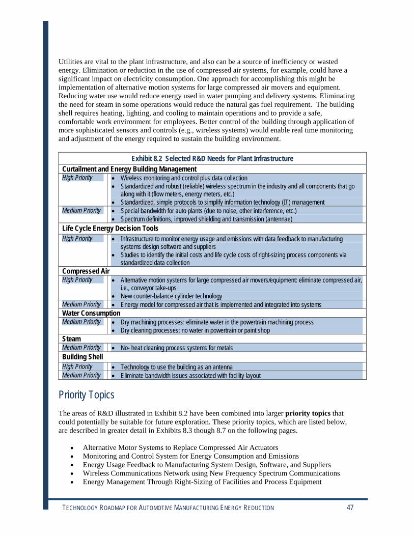
Utilities are vital to the plant infrastructure, and also can be a source of inefficiency or wasted energy. Elimination or reduction in the use of compressed air systems, for example, could have a significant impact on electricity consumption. One approach for accomplishing this might be implementation of alternative motion systems for large compressed air movers and equipment. Reducing water use would reduce energy used in water pumping and delivery systems. Eliminating the need for steam in some operations would reduce the natural gas fuel requirement. The building shell requires heating, lighting, and cooling to maintain operations and to provide a safe, comfortable work environment for employees. Better control of the building through application of more sophisticated sensors and controls (e.g., wireless systems) would enable real time monitoring and adjustment of the energy required to sustain the building environment.
Exhibit 8.2 Selected R&D Needs for Plant Infrastructure Curtailment and Energy Building Management High Priority • Wireless monitoring and control plus data collection
• Standardized and robust (reliable) wireless spectrum in the industry and all components that go along with it (flow meters, energy meters, etc.)
• Standardized, simple protocols to simplify information technology (IT) management Medium Priority • Special bandwidth for auto plants (due to noise, other interference, etc.)
• Spectrum definitions, improved shielding and transmission (antennae) Life Cycle Energy Decision Tools High Priority • Infrastructure to monitor energy usage and emissions with data feedback to manufacturing
systems design software and suppliers • Studies to identify the initial costs and life cycle costs of right-sizing process components via
standardized data collection Compressed Air High Priority • Alternative motion systems for large compressed air movers/equipment: eliminate compressed air,
i.e., conveyor take-ups • New counter-balance cylinder technology
Medium Priority • Energy model for compressed air that is implemented and integrated into systems Water Consumption Medium Priority • Dry machining processes: eliminate water in the powertrain machining process
• Dry cleaning processes: no water in powertrain or paint shop Steam Medium Priority • No- heat cleaning process systems for metals Building Shell High Priority • Technology to use the building as an antenna Medium Priority • Eliminate bandwidth issues associated with facility layout
Priority Topics The areas of R&D illustrated in Exhibit 8.2 have been combined into larger priority topics that could potentially be suitable for future exploration. These priority topics, which are listed below, are described in greater detail in Exhibits 8.3 though 8.7 on the following pages.
• Alternative Motor Systems to Replace Compressed Air Actuators • Monitoring and Control System for Energy Consumption and Emissions • Energy Usage Feedback to Manufacturing System Design, Software, and Suppliers • Wireless Communications Network using New Frequency Spectrum Communications • Energy Management Through Right-Sizing of Facilities and Process Equipment
TECHNOLOGY ROADMAP FOR AUTOMOTIVE MANUFACTURING ENERGY REDUCTION 47

Applications• CNC machine and stamping counter balance
• Linear motion cylinders
• Conveyor take ups
• Paint delivery systems
R&D TimelineIndus collaboration OEMs, suppliers, etc.
Pain delivery systems that do not use co
airAnalyze performance and refine designs
Deploy second generation solutions
RisksTechnical• Durability, weight
Commercial
Alternative Motor Systems to Replace Compressed Air ActuatorsExplore ways to replace compressed air actuators with CNC machines, stamping counter balances,
and conveyor take ups
Exhibit 8.3 Priority Topic Plant Infrastructure
‐
Near ‐ try ‐ DOE,
‐ Study, prototype, pilot‐ OEMs to update specifications
Mid ‐ Deploy first generation solutions‐ t mpressed
‐
Long ‐
PartnersI – Collaboration betweenAuto OEMs and suppliers
F, U, G – R&D on mechanicalsolution
Targets• Non‐pneumaticapplication to replacecompressed airactuators
• Solutions may bemechanical, magnetic,or either
• Solutions must be life‐cycle cost effective
• Solutions must bedurable
BenefitsEnergy• Reduced powerconsumption
Environment• Reduced emissions,improved indoor air quality
Economics• Cost‐neutral, reduceddowntime, improved quality
Challenges• Durability
• Cost (life cycle)
•Weight
‐
8.31.09
Applications • CNC machine and stamping counter balance
• Linear motion cylinders
• Conveyor take‐ups
• Paint delivery systems
R&D Timeline Near ‐ Industry collaboration ‐ OEMs, suppliers, DOE,
etc. ‐ Study, prototype, pilot ‐ OEMs to update specifications
Mid ‐ Deploy first generation solutions ‐ Paint delivery systems that do not use compressed air ‐ Analyze performance and refine designs
Long ‐ Deploy second generation solutions
Partners I – Collaboration between Auto OEMs and suppliers
F, U, G – R&D on mechanical solution
Targets • Non‐pneumatic application to replace compressed air actuators
• Solutions may be mechanical, magnetic, or either
• Solutions must be life‐cycle cost effective
• Solutions must be durable
Benefits Energy • Reduced power consumption
Environment • Reduced emissions, improved indoor air quality
Economics • Cost‐neutral, reduced downtime, improved quality
Challenges • Durability
• Cost (life cycle)
• Weight
Risks Technical • Durability, weight
Commercial
Alternative Motor Systems to Replace Compressed Air Actuators Explore ways to replace compressed air actuators with CNC machines, stamping counter balances,
and conveyor take‐ups
8.31.09
TECHNOLOGY ROADMAP FOR AUTOMOTIVE MANUFACTURING ENERGY REDUCTION 48

Applications• Energy management (BIM)
• Emissions monitoring
• Equipment PLM
• Discrete I/O control
R&D Timelines cost analysis
De wireless specification
s e e e
Industry acceptance (e.g., IEEE, SP100)Large scale deployment in commercial Energy data made available to suppliers for
saving ideas
• Existing plant RFI
• Achieving ~100% up‐time
RisksTechnical• May be unable to bridge caps, speed, cost
Commercial• May not become industry standard
Monitoring and Control System for Energy Consumption and Emissions
Monitoring and control system to measure and optimize energy consumption and emissions, for discrete manufacturing (automotive)
‐
Exhibit 8.4 Priority Topic Plant Infrastructure
Near ‐Wireles‐ velop‐ Identify technical gaps for wireless
Mid ‐ Develop prototype sensor network system‐ Beta te t sit d ploym nt
Long ‐‐ ‐ world‐ cost‐
PartnersI – Beta test site,commercialization
F – Technology development
U – N/A
G – Cost sharing
Targets• Component/machinelevel system with lowacquisition, installation,and maintenance cost
• Low power, secure,and reliable responsetime under 10ms
BenefitsEnergy• Establish energy baseline atcomponent level tosubstantially reduce energyconsumption inmanufacturing
Environment• Establish emissions footprintfor manufacturingsubstantially reduce it
Economics• Significant cost benefits dueto innovative energy andemissions management
Challenges• Response time
• Developing a low cost solution• Spectrum availability
•Wireless power supply
8.31.09
Applications • Energy management (BIM)
• Emissions monitoring
• Equipment PLM
• Discrete I/O control
R&D Timeline Near ‐Wireless cost analysis
‐ Develop wireless specification ‐ Identify technical gaps for wireless
Mid ‐ Develop prototype sensor network system ‐ Beta test site deployment
Long ‐ Industry acceptance (e.g., IEEE, SP100) ‐ Large‐scale deployment in commercial world ‐ Energy data made available to suppliers for cost‐saving ideas
Partners I – Beta test site, commercialization
F – Technology development
U – N/A
G – Cost sharing
Targets • Component/machine level system with low acquisition, installation, and maintenance cost
• Low power, secure, and reliable response time under 10ms
Benefits Energy • Establish energy baseline at component level to substantially reduce energy consumption in manufacturing
Environment • Establish emissions footprint for manufacturing substantially reduce it
Economics • Significant cost benefits due to innovative energy and emissions management
Challenges • Response time
• Developing a low cost solution
• Spectrum availability
• Wireless power supply
• Existing plant RFI
• Achieving ~100% up time
Risks Technical • May be unable to bridge caps, speed, cost
Commercial • May not become industry standard
Monitoring and Control System for Energy Consumption and Emissions
Monitoring and control system to measure and optimize energy consumption and emissions, for discrete manufacturing (automotive)
8.31.09
TECHNOLOGY ROADMAP FOR AUTOMOTIVE MANUFACTURING ENERGY REDUCTION 49

Applications• Process monitoring and optimization with resulting efficiencies and improved cost competitiveness
• Make and process feedback to plant and suppliers for equipment monitor and process optimization
• Robust manufacturing systems, proactive maintenance, and the opportunity for innovative, optimized process equipment
R&D Timeline
Continue to refine and improve feedback based on performance and resultsExplore/implement new sensor and contro
technologies as breakthroughs emerge
‐
‐
• Installation costs, ROI
RisksTechnical• Very low perceived risk; benign monitoring onlyCommercial• Very low perceived risk; generally standard protocols existOther
Energy Usage Feedback to Manufacturing System Design, Software, and Suppliers
Internet accessible, plant wide data collection via sensor technology and protocols allowing for “drill down” compatibility for all physical criteria, such as pressure, flow, temperature, energy use, etc., to
monitor and establish effective response action, data collection, and process optimization
‐
‐
Exhibit 8.5 Priority Topic Plant Infrastructure
‐
Near ‐ Standardize protocol for data type and collectionwith supplier‐ Develop pilot program with data collection
Mid ‐ systems
‐ l
Partners• I, F, G
• USCAR and NIST/FCC/NAM,equipment vendors, suppliers,DOE (funding and facilitation)working together
Targets• Non‐intrusive sensors
• Real‐time datacollection
• Plug and playconnectivity for allsensors and end users
BenefitsEnergy, Environment,Economics• Ability to prioritize andproactively address issuesleading to optimized systems.Better maintenance, energy,environmental management
Challenges• Non intrusive compressed air flowmonitoring
• Current lack of sub metering datacollection, including gas and water
• Moving forward with competingprotocols is NG
‐
8.31.09
Applications • Process monitoring and optimization with resulting efficiencies and improved cost‐competitiveness
• Make and process feedback to plant and suppliers for equipment monitor and process optimization
• Robust manufacturing systems, proactive maintenance, and the opportunity for innovative, optimized process equipment
R&D Timeline Near ‐ Standardize protocol for data type and collection
with supplier ‐ Develop pilot program with data collection
Mid ‐ Continue to refine and improve feedback systems based on performance and results ‐ Explore/implement new sensor and control technologies as breakthroughs emerge
Partners • I, F, G
• USCAR and NIST/FCC/NAM, equipment vendors, suppliers, DOE (funding and facilitation) working together
Targets • Non‐intrusive sensors
• Real‐time data collection
• Plug and play connectivity for all sensors and end users
Benefits Energy, Environment, Economics • Ability to prioritize and proactively address issues leading to optimized systems. Better maintenance, energy, environmental management
Challenges • Non intrusive compressed air flow monitoring
• Current lack of sub metering data collection, including gas and water
• Installation costs, ROI
Risks Technical • Very low perceived risk; benign monitoring only Commercial • Very low perceived risk; generally standard protocols exist Other • Moving forward with competing protocols is NG
Energy Usage Feedback to Manufacturing System Design, Software, and Suppliers
Internet accessible, plant‐wide data collection via sensor technology and protocols allowing for “drill down” compatibility for all physical criteria, such as pressure, flow, temperature, energy use, etc., to
monitor and establish effective response action, data collection, and process optimization
8.31.09
TECHNOLOGY ROADMAP FOR AUTOMOTIVE MANUFACTURING ENERGY REDUCTION 50

Applications• Applicable wherever life/safety concerns exist
• HVAC controls, pressure and temperature sensors, capacitor noise filters, and antenna technologies
R&D TimelineDefine wireless network applications,
devices, and architecture for EMS at typical plantAssess production environment for EMI “n
Validate through beta testing of best availa technologies and hardware in an auto plant environment
Replicate systems and devices to other pla applications, and production equipmentMaintain common systems and open prot
with network security and encryption
with new technologies and frequency spectrums
RisksTechnical• Reliability criteria not achievable due to noise and technical limitations
Commercial• Spectrum already assigned
Wireless Communications Network Utilizing New Frequency Spectrum Communications
Develop a reliable, standardized, wireless industrial service network to monitor and control energy and building systems by utilizing new frequency spectrum(s)
Exhibit 8.6 Priority Topic Plant Infrastructure
Near ‐ systems,auto
‐ oise”interference and existing technologies
Mid ‐ Test, analyze, and recommend frequencies andspectrums suitable for reliable operations‐ ble
Long ‐ nts,
‐ ocols
PartnersI – JCI, Honeywell, Benham,3ETI, Lucent
F – NIST
U – UDRI
G – FCC, FTC, DOE Labs
Targets• Define systemrequirement and metricfor typical integrationinto automotivefacilities
• Examine existingsystems, facilities andspectrums for cost andreliability
• Examine newtechnologies andfrequencies emergingthat could improve cost,reliability, or capability
BenefitsEnergyEnvironmentEconomicsOther• Technologies available forreplication, new applications,and/or export
Challenges• Reduce installation costs and improvereliability of critical systems forproduction• Standardize IT systems for replicationon diverse network applications• Overcome “noise”– EM interference–
8.31.09
Applications • Applicable wherever life/safety concerns exist
• HVAC controls, pressure and temperature sensors, capacitor noise filters, and antenna technologies
R&D Timeline Near ‐ Define wireless network applications, systems,
devices, and architecture for EMS at typical auto plant ‐ Assess production environment for EMI “noise” interference and existing technologies
Mid ‐ Test, analyze, and recommend frequencies and spectrums suitable for reliable operations ‐ Validate through beta testing of best available technologies and hardware in an auto plant environment
Long ‐ Replicate systems and devices to other plants, applications, and production equipment ‐Maintain common systems and open protocols with network security and encryption
Partners I – JCI, Honeywell, Benham, 3ETI, Lucent
F – NIST
U – UDRI
G – FCC, FTC, DOE Labs
Targets • Define system requirement and metric for typical integration into automotive facilities
• Examine existing systems, facilities and spectrums for cost and reliability
• Examine new technologies and frequencies emerging that could improve cost, reliability, or capability
Benefits Energy Environment Economics Other • Technologies available for replication, new applications, and/or export
Challenges • Reduce installation costs and improve reliability of critical systems for production • Standardize IT systems for replication on diverse network applications • Overcome “noise”– EM interference– with new technologies and frequency spectrums
Risks Technical • Reliability criteria not achievable due to noise and technical limitations
Commercial • Spectrum already assigned
Wireless Communications Network Utilizing New Frequency Spectrum Communications
Develop a reliable, standardized, wireless industrial service network to monitor and control energy and building systems by utilizing new frequency spectrum(s)
8.31.09
TECHNOLOGY ROADMAP FOR AUTOMOTIVE MANUFACTURING ENERGY REDUCTION 51

Applications• Facilities design and operation
• Manufacturing systems design and operation
R&D TimelineGat er energy and emissions dataDe ener model
yout for energy efficient facilities and equipment design
Design for Energy Consumption (DFEC)
RisksTechnical• Data collection with feedback loop to PLM is challenging
Commercial• PLM integration may be challenging
Energy Management Through Right‐Sizing of Facilities/Process Equipment
Life cycle asset management of facilities and process equipment to reduce over sizing and other practices that lead to excessive energy losses or consumption
Exhibit 8.6 Priority Topic Plant Infrastructure
Near ‐ h‐ velop gy
Mid ‐ Develop Product Lifecycle Management (PLM)model‐ La ‐ process
Long ‐
PartnersI – Data collection, Beta testsite
F – PLM integration
U – DFEC program
G – Cost sharing, partnershipswith energy
Targets• Reduce plant energyconsumption andemissions through right‐sizing of facilities andprocess equipment
• Cost reduction ofcapital equipment
BenefitsEnergy• DFEC (trademark pending)
Environment• Goes hand‐in‐hand withenergy consumption
Economics• Plants will become moreefficient
Other• Provides real‐time data formanaging change
Challenges• Accurate data collection
• Analytical models for energymanagement
‐
8.31.09
Applications • Facilities design and operation
• Manufacturing systems design and operation
R&D Timeline Near ‐ Gather energy and emissions data
‐ Develop energy model
Mid ‐ Develop Product Lifecycle Management (PLM) model ‐ Layout for energy‐efficient facilities and process equipment design
Long ‐ Design for Energy Consumption (DFEC)
Partners I – Data collection, Beta test site
F – PLM integration
U – DFEC program
G – Cost sharing, partnerships with energy
Targets • Reduce plant energy consumption and emissions through right‐sizing of facilities and process equipment
• Cost reduction of capital equipment
Benefits Energy • DFEC (trademark pending)
Environment • Goes hand‐in‐hand with energy consumption
Economics • Plants will become more efficient
Other • Provides real‐time data for managing change
Challenges • Accurate data collection
• Analytical models for energy management
Risks Technical • Data collection with feedback loop to PLM is challenging
Commercial • PLM integration may be challenging
Energy Management Through Right‐Sizing of Facilities/Process Equipment
Life cycle asset management of facilities and process equipment to reduce over‐sizing and other practices that lead to excessive energy losses or consumption
8.31.09
TECHNOLOGY ROADMAP FOR AUTOMOTIVE MANUFACTURING ENERGY REDUCTION 52

9.0 Crosscutting Opportunities for Saving Energy There are a number of opportunities for reducing energy or increasing efficiency that cut across many parts of the automotive enterprise. These crosscutting energy concepts could be widely applied – with concomitantly large energy benefits. These include energy recovery; assessing, predicting, and modeling energy consumption; and others.
Energy Recovery Opportunities for energy recovery in automotive manufacturing have been identified that have the potential to directly reduce energy consumption. These opportunities cover a range of processes, from curing and drying in paint, to metal and materials processing and recovering the energy embodied in scrap. These concepts could theoretically be applied by an automotive OEM or in supplier operations.
The recovery of energy from bulk materials manufacture is seen as one opportunity that could provide substantial energy savings and provide favorable environmental impacts as well (see Exhibit 9.1). Bulk manufacture of metals is one example where energy recovery could be applied in supplier plants.
Some of the most important ideas for energy recovery are shown below. These are not all-inclusive, but show the breadth of possibilities.
• Recovery of heat from casting of metal (e.g., heat of fusion, sheet products, etc.) or heat treating of metals
• Recovery of energy from bulk materials manufacturing (slabs, sheets, ingots) • Incineration of plastic scrap to generate power and heat and augment the power grid of the
plant • Alternative cooling technology (e.g., cooling water, eliminating fans) with a means of
recapturing lost energy, or recovery of energy from cooling fluids • Ways to efficiently recover and reuse low temperature waste heat (salt bath, cooling water,
etc.) • Thermal regeneration processes to capture and reuse waste heat • Capture waste heat to improve tool efficiency or for use in other applications
Combined heat and power (CHP) is one means of effectively utilizing waste heat from various sources throughout the plant. The economic feasibility of using CHP for this purpose depends on the quality (temperature) and quantity of waste heat, the reliability of the source, and plant needs for electricity or heat near the proposed location of the CHP system. There may also be issues with how easily CHP can be integrated into the current plant configuration, and the cost of the system (and return on investment (ROI)). CHP systems are costly to construct and maintain and are usually most viable above a certain power and heat generation level. The advent of small, modular CHP systems and other power generators such as fuel cells could make it easier to implement CHP systems for smaller-volume heat recovery applications in the future.
TECHNOLOGY ROADMAP FOR AUTOMOTIVE MANUFACTURING ENERGY REDUCTION 53

Applications• Casting slabs/sheets/ingots of metals (recover latent heat and cooling energy)
• Recovery of radiant heat losses from equipment in basic metals plants (e.g., from melting/holding furnaces, rolling mills, etc.)
R&D TimelineSurvey ways of recovering heat, select ca
with capability to handle metal production
Outline conceptual system design
Conduct needed R&D on aspects of systemDemonstrate processes on pilot scale
Integrate and demonstrate technologies production level
• Energy conversion into form amenable to transmission and storage
• Economical, containable devices and methods
RisksTechnical • Unidentified method/technologies for accomplishing goals – very high amount of energy, large volumes of water/air containing low‐grade energyCommercial
Recovery of Process Energy from Bulk Materials ManufacturingMethods to capture and reuse energy needed to produce metals in bulk forms; entails conversion of
hot air and hot water into usable/reusable energy
‐
Exhibit 9.1 Crosscutting Priority R&D Topic
Near ‐ ndidates
processes‐ Quantify and characterize heat in metalproduction processes‐ Identify needed R&D‐
Mid ‐‐
Long ‐ on
PartnersF, U – Identify/develop/inventbasic energy collection andconversion processes andmechanisms
I, F – Develop pilot anddemonstrate the technologies
Targets• Reduced net energyconsumption inmaterials production
BenefitsEnergy• This is a large fraction of theenergy consumed in theproduction of bulk metals
Environment• Currently this energy isdissipated into theenvironment
Economics• If process energy could beeffectively recycled/reused, itwould have a major favorableeconomic impact
Challenges• Heat transfer media
• Technologies must be compact andeconomical
8.31.09
Applications • Casting slabs/sheets/ingots of metals (recover latent heat and cooling energy)
• Recovery of radiant heat losses from equipment in basic metals plants (e.g., from melting/holding furnaces, rolling mills, etc.)
R&D Timeline Near ‐ Survey ways of recovering heat, select candidates
with capability to handle metal production processes ‐ Quantify and characterize heat in metal production processes ‐ Identify needed R&D ‐ Outline conceptual system design
Mid ‐ Conduct needed R&D on aspects of system ‐ Demonstrate processes on pilot scale
Long ‐ Integrate and demonstrate technologies on production level
Partners F, U – Identify/develop/invent basic energy collection and conversion processes and mechanisms
I, F – Develop pilot and demonstrate the technologies
Targets • Reduced net energy consumption in materials production
Benefits Energy • This is a large fraction of the energy consumed in the production of bulk metals
Environment • Currently this energy is dissipated into the environment
Economics • If process energy could be effectively recycled/reused, it would have a major favorable economic impact
Challenges • Heat transfer media
• Energy conversion into form amenable to transmission and storage
• Economical, containable devices and methods
Risks Technical • Unidentified method/technologies for accomplishing goals – very high amount of energy, large volumes of water/air containing low grade energy Commercial • Technologies must be compact and economical
Recovery of Process Energy from Bulk Materials Manufacturing Methods to capture and reuse energy needed to produce metals in bulk forms; entails conversion of
hot air and hot water into usable/reusable energy
8.31.09
TECHNOLOGY ROADMAP FOR AUTOMOTIVE MANUFACTURING ENERGY REDUCTION 54

Assessing, Predicting, and Modeling Energy Consumption A major factor in identifying the source and magnitude of opportunities for energy efficiency improvements is a solid understanding of energy use in process operations. While some processes are well known as large energy consumers, the energy footprints of others are less transparent. For example, while a single robot or conveyor may be a small consumer of energy, when this single piece of equipment is multiplied a hundred-fold, the aggregate energy use may be substantial. Without a targeted understanding of the magnitude of energy use in processes, sub-processes, and facilities, it is more difficult to justify where to focus investments in energy efficiency.
The level of information on energy use in automotive manufacturing varies significantly between plants and processes in use. Many factors impact energy consumption at the site of manufacturing and all sites are different. The mix of automated and manual systems, and the types of processes (and the energy they use) can often vary substantially between plants, and within the same company. This site-specific variation in energy use makes it difficult to apply a one-size-fits-all paradigm to reducing energy use. The lack of metering and monitoring of energy except for large energy-consuming equipment is also a limiting factor.
Despite these uncertainties, there are some general concepts that could be applied to gain an understanding of energy sources and sinks in automotive manufacturing in order to aid in decision-making. These include building understanding in some key areas:
• Value-added versus non-value added energy consumed in processes • Energy sinks in functional areas of the plant, including processes and sub-processes and
the building envelope (HVAC, etc.) • Energy attributed to plant-wide logistical operations such as moving of materials or parts
from one area to another • Energy consumption that is embedded in the materials of construction and use in parts and
components, from raw materials to finished products • Source and function of energy (electrical, air, motion, hydraulic) • How models and simulation can pinpoint targets of opportunity
Two priority R&D topics have been identified that relate specifically to understanding energy consumption in the automotive enterprise. The first deals with assessing the energy footprint of automotive manufacturing unit operations and the associated supplier base, as shown in Exhibit 9.2. The second effort, illustrated in Exhibit 9.3, focuses on using data from various sources to model and predict the patterns and sensitivities in energy consumption throughout the automotive enterprise, from raw materials to suppliers of parts and components to OEM manufacture. Combined, the tools that results from the efforts shown in Exhibits 9.2 and 9.3 would provide a basis for strategic planning and decision making for energy efficiency and related projects.
TECHNOLOGY ROADMAP FOR AUTOMOTIVE MANUFACTURING ENERGY REDUCTION 55

Applications• Energy opportunity targets in automotive (OEMs and supplier base)
• Energy targets in similar industries (e.g., other transport manufacture, heavy equipment)
• Models for energy simulation and prediction
R&D TimelineEne flow di rams 0
st es, benchmarking (2012/on
Continue to update and improve model
• Lack of access to data
• Availability of motors‐component level data
• Variations and methods of capturing energy data
RisksTechnical• Changing energy profiles
Commercial• Changing product profiles
Business
Assessing Opportunities for Energy Reduction in Vehicle Manufacture
Understand the energy flows in making a vehicle
‐
Exhibit 9.2 Crosscutting R&D Priority Topic
Near ‐ rgy ag (2 09)‐ Assessments/Validation (2009/2010)‐ Pareto diagram of energy use (2010/2011)
Mid ‐ Be practic going)
Long ‐
PartnersI – OEMs, suppliers, utilitysupply, equipment suppliers(input and feedback)
F – Data gathering andmapping and modeling
G – Funding forprecompetitive aspects
Targets• Energy use inmanufacturing allvehicle systems andcomponents
• Targeted goals andopportunities for energyreduction
BenefitsEnergy
Environment
Economics
Challenges• Competitive data
• Possibility of revealing informationfor OEM or supplier
8.31.09
Applications • Energy opportunity targets in automotive (OEMs and supplier base)
• Energy targets in similar industries (e.g., other transport manufacture, heavy equipment)
• Models for energy simulation and prediction
R&D Timeline Near ‐ Energy flow diagrams (2009)
‐ Assessments/Validation (2009/2010) ‐ Pareto diagram of energy use (2010/2011)
Mid ‐ Best practices, benchmarking (2012/ongoing)
Long ‐ Continue to update and improve model
Partners I – OEMs, suppliers, utility supply, equipment suppliers (input and feedback)
F – Data gathering and mapping and modeling
G – Funding for precompetitive aspects
Targets • Energy use in manufacturing all vehicle systems and components
• Targeted goals and opportunities for energy reduction
Benefits Energy
Environment
Economics
Challenges • Competitive data
• Lack of access to data
• Availability of motors component level data
• Variations and methods of capturing energy data
Risks Technical • Changing energy profiles
Commercial • Changing product profiles
Business • Possibility of revealing information for OEM or supplier
Assessing Opportunities for Energy Reduction in Vehicle Manufacture
Understand the energy flows in making a vehicle
8.31.09
TECHNOLOGY ROADMAP FOR AUTOMOTIVE MANUFACTURING ENERGY REDUCTION 56

Applications• Building designs
• Product designs
• Selection of energy reduction opportunities and projects
• Development and execution of energy management plans
• Strategic business decision making support
R&D TimelineEstablish energy baselines for model
utilizing tools such as EPA, EPI, and others, appropriateStudy the fully accounted cost of recyclab
able dunnageDe a material content and logistics
capa
Develop virtual engineering tools for co product/process design incorporating energInvestigate and analyze interface and trade
between throughput, quality, and energy us Include energy utilization factors in prod
for manufacturing
Reverse logistics: consider product life cyc from raw material to use of raw material
ve p ng ou pu s su e
engineering decision• Interoperability across business units and platforms
RisksTechnical
Commercial
Other• Complexity and dynamics of the supply chain can lead to inaccurate
Modeling and Simulation for Energy ReductionDevelop mathematical models and simulation tools to assess the relative sensitivities in energy
consumption through the supply chain, from raw materials to final assembly
Exhibit 9.3 Crosscutting R&D Priority Topic
‐
Near ‐ calibration,as
‐ ‐ le vs.return‐ velop energysimulation model (raw materials to assembly)‐ Develop total building process energy math modelunder different operating scenarios (zero to full
city)
Mid ‐ ncurrenty
‐ ‐offse
‐ uct design
Long ‐ ‐ le
PartnersI – Lead, provide data, definescope, usability, benchmark,beta test, validate
F – Design experiments,develop algorithms,interoperability, computingpower, validate
U – Develop algorithms
G – Provide data, fund
TargetsSoftware tools to modelenergy usage that can:
• Analyze energydistribution, use,optimization, integrationfor concurrent product/process design;
• Separate building energyfrom process energy, value‐added from non‐valueadded;
• Perform trade‐offanalysis;
• Provide decision‐makingsupport for various issues
To predict relative energydistribution at differentproduction loads
BenefitsEnergy
Environment
Economics• Used in prioritizing andmaximizing the synergeticeffects of project selection
BenefitsEnergy
Environment
Economics• Used in prioritizing andmaximizing the synergeticeffects of project selection
Challenges• Funding/Cost• Acquiring baseline data applicableacross the industry• Equitable ways to measure energyutilization and carbon allocation• Complexity of integrating all systemsand processes• De lo i t t itabl for
modeling
8.31.09
Applications • Building designs
• Product designs
• Selection of energy reduction opportunities and projects
• Development and execution of energy management plans
• Strategic business decision‐making support
R&D Timeline Near ‐ Establish energy baselines for model calibration,
utilizing tools such as EPA, EPI, and others, as appropriate ‐ Study the fully‐accounted cost of recyclable vs. returnable dunnage ‐ Develop a material content and logistics energy simulation model (raw materials to assembly) ‐ Develop total building process energy math model under different operating scenarios (zero to full capacity)
Mid ‐ Develop virtual engineering tools for concurrent product/process design incorporating energy ‐ Investigate and analyze interface and trade‐offs between throughput, quality, and energy use ‐ Include energy utilization factors in product design for manufacturing
Long ‐ Reverse logistics: consider product life‐cycle from raw material to use of raw material
Partners I – Lead, provide data, define scope, usability, benchmark, beta test, validate
F – Design experiments, develop algorithms, interoperability, computing power, validate
U – Develop algorithms
G – Provide data, fund
Targets Software tools to model energy usage that can:
• Analyze energy distribution, use, optimization, integration for concurrent product/ process design;
• Separate building energy from process energy, value‐added from non‐value added;
• Perform trade‐off analysis;
• Provide decision‐making support for various issues
To predict relative energy distribution at different production loads
BenefitsEnergy
Environment
Economics• Used in prioritizing andmaximizing the synergeticeffects of project selection
Benefits Energy
Environment
Economics • Used in prioritizing and maximizing the synergetic effects of project selection
Challenges • Funding/Cost • Acquiring baseline data applicable across the industry • Equitable ways to measure energy utilization and carbon allocation • Complexity of integrating all systems and processes • Developing outputs suitable for engineering decision • Interoperability across business units and platforms
Risks Technical
Commercial
Other • Complexity and dynamics of the supply chain can lead to inaccurate modeling
Modeling and Simulation for Energy Reduction Develop mathematical models and simulation tools to assess the relative sensitivities in energy
consumption through the supply chain, from raw materials to final assembly
8.31.09
TECHNOLOGY ROADMAP FOR AUTOMOTIVE MANUFACTURING ENERGY REDUCTION 57

Other Crosscutting Topics Other crosscutting topics are:
• Wireless systems for control and monitoring – expansion and improvement of wireless systems was noted in several areas as a way to improve energy efficiency. Concepts include wireless systems for materials handling, tracking and sequencing parts and components; plant-wide use of wireless; and standardized wireless spectrum for all building and infrastructure systems, potentially utilizing the building shells as antennae.
• Design for energy consumption – incorporation of energy into design practices and plant layout is a concept that could ultimately reduce energy use throughout the vehicle life cycle. Ideas include consolidation of parts, design for part and material reuse, and elimination of process steps.
• Materials –the development and implementation of new materials is a high priority in a number of areas. Materials improvements range from new light-weight, high-strength, formable materials, to low-carbon materials and innovative coatings and paint formulations. Materials to enable scrap reduction and/or that are reusable is another concept of interest.
TECHNOLOGY ROADMAP FOR AUTOMOTIVE MANUFACTURING ENERGY REDUCTION 58

10.0 Moving Forward Creation of this technology roadmap represented a focused effort to understand the opportunities for reducing energy consumption in automotive manufacturing and the associated supply chain. Clearly, the opportunities are many and span every aspect of the industry.
It is hoped that this roadmap will provide direction and a basis for future decision making and investments in R&D to enable energy reduction in automotive manufacturing. While it does not cover all areas in depth, it does bring out some important ideas. It is notable that the concepts presented here represent a wide range of technologies and opportunities – from the very near-term to revolutionary changes that could be achieved in the future. One thing is certain – the automotive enterprise will continue to adapt and improve to meet approaching energy challenges.
Looking forward, this roadmap illuminates some of the key opportunities for energy efficiency in the automotive enterprise that can potentially be achieved through R&D and other actions. Developing these energy efficiency gains may require long-term, high-risk research, and the foundation of new public-private collaborations involving academia, national labs, government, OEMs, and suppliers. As future R&D projects are initiated, the automotive industry and the nation can begin to reap the benefits that accrue from reducing the use of our precious energy resources.
This roadmap is dynamic – it will continue to change and be refined and expanded as more industry participants become involved and as technology breakthroughs emerge.
TECHNOLOGY ROADMAP FOR AUTOMOTIVE MANUFACTURING ENERGY REDUCTION 59

(this page intentionally left blank)
TECHNOLOGY ROADMAP FOR AUTOMOTIVE MANUFACTURING ENERGY REDUCTION 60

APPENDIX A: List of Contributors Bill Allemon Ford Motor Company [email protected]
George Andrews General Motors Corp [email protected]
Rex Armstrong Chrysler, LLC. [email protected]
Bob Baird General Motors Corp [email protected]
Margaret Baxter Original Equipment Suppliers Assoc. [email protected]
Kay Bedenis Chrysler, LLC. [email protected]
Victor Bell Chrysler [email protected]
Raymond Betham General Motors Corp [email protected]
Stephan Biller General Motors Corp [email protected]
Craig Blue Oak Ridge National Laboratory [email protected]
Dennis Blumenfeld General Motors Corp [email protected]
Laura Brandt TRW Automotive [email protected]
Henry Casinelli Ford Motor Company [email protected]
Troy Casteel Maxon Corporation [email protected]
Isaac Chan U.S. Department of Energy [email protected]
Bill Charron Ford Motor Company [email protected]
Mark Cline General Motors Corp [email protected]
Matthew Daraskavich Ford Motor Company [email protected]
Paula Deeds General Motors Corp [email protected]
Melissa Eichner Energetics Incorporated [email protected]
John Eidt Ford Motor Company [email protected]
Rick Gerth Center for Automotive Research [email protected]
John Goetzmann General Motors Corp [email protected]
Tom Gustafson General Motors Corp [email protected]
Yoram Guy ZF Group NA [email protected]
Gordon Harbison Durr Systems, Inc [email protected]
Brad Hare The BAM Group, Inc. [email protected]
Roger Heimbuch Auto/Steel Partnership [email protected]
Karen Henderson Bayer MaterialScience karen.henderson@bayerbms. com
Jack Hu University of Michigan [email protected]
Rich Hutchins Chrysler, LLC. [email protected]
Jon Jennings EWI [email protected]
Don Jordan Ford Motor Company [email protected]
A-1

Doug Kaempf U.S. Department of Energy [email protected]
Dean Kanelos Nucor [email protected]
Charlotte Kelly General Motors R&D [email protected]
Tim Kelly PCE Monarch [email protected]
John Kimball U.S. Department of Energy [email protected]
Menachem Kimchi Edison Welding Institute [email protected]
Pradeep Kokate Process Control & Engineering, Inc. [email protected]
Bob Konicki Ford Motor Company [email protected]
Bill Kramer Automotive Components Holdings, LLC [email protected]
Steve Lepper Retired Dow Chemical [email protected]
Kevin Lyons National Institute of Standards and Technology [email protected]
Nancy Margolis Energetics Incorporated [email protected]
Shawna McQueen Energetics Incorporated [email protected]
Rachel Meck Federal-Mogul Corporation [email protected]
Gordon Nader Ford Land & Detroit Edison [email protected]
Tom Neelands General Motors Corp [email protected]
Jim Nicholson Ford Motor Company [email protected]
James Ohlinger PPG Industries [email protected]
Mark Osborne General Motors
Dean Paxton U.S. Department of Energy [email protected]
Joan Pellegrino Energetics Incorporated [email protected]
Paul Platte Bayer MaterialScience [email protected]
Patrick Ryan Ford Motor Company [email protected]
Rich Saad General Motors Corp [email protected]
Scott Schramm Chrysler, LLC. [email protected]
Rob Seats Ashland, Inc. [email protected]
Andy Sherman Ford Motor Company [email protected]
Ming Shi United States Steel Corporation [email protected]
Phil Sklad Oak Ridge National Laboratory [email protected]
Mark Smith Pacific Northwest National Laboratory [email protected]
Susan Smyth General Motors R&D [email protected]
Reg Sobczynski General Motors Corp [email protected]
Brad Spear Energetics Incorporated [email protected]
Raj Suthar Ford Motor Company [email protected]
Janice Tardiff Ford Motor Company [email protected]
Jeffrey Tew General Motors Corp [email protected]
Chip Tolle Idaho National Lab [email protected]
A-2

Don Walkowicz United States Council for Automotive Research (USCAR)
Scott Walters Chrysler, LLC. [email protected]
Qigui Wang General Motors Corp. [email protected]
Phil Wilson BASF [email protected]
Larry Workens Chrysler, LLC. [email protected]
Jie Xiao General Motors R&D [email protected]
Faiz Yono Chrysler, LLC. [email protected]
Kurt Zabel Siemens Building Technologies [email protected]
Bill Zdeblick Federal-Mogul Corporation Bill.Zdeblick@federalmogul. com
John Ziegert Clemson University [email protected] du
Aaron Zoeller Maxon Corporation [email protected]
A-3

(this page left intentionally blank)
A-4

APPENDIX B: Comprehensive List of R&D Needs
R&D NEEDS – BODY IN WHITE (MANUFACTURING PROCESSES)
Joining Modeling/ Studies
Efficient Vehicle Part Forming Shape
• Solid state joining methods - similar materials, dissimilar materials - ultrasonic, magnetic, pulse ●●●●●● • Non-heat cured adhesives -
induction ●●●● • New hybrid joining methods
mixing technology - welding and adhesives, mix processes, fasteners and adhesives, laser assist arc welding ●● • Multi-material casting -
explore metals/ processes that self-bond “cast-in” to create metallurgical bond • Enablers to laser welding –
part design, tooling, methods to get better parts out of dies (not the design of the laser itself)
• Assessment of energy use in material forming processes/joining processes used to create substructures ●●●●●●●●●
• Definition of current energy consumption for current materials as benchmark (need in order to compare alternatives)
• Predictive material properties (design, waste) ●●●● and
• Better software to predict - formability, spring back, joining, processing
• Mathematical model to predict material properties in material manufacturing
• Process models to optimize balance of number parts (higher yield) vs. other goals ●●●
• Virtual functional build (during launch of prototypes) • Next generation CAD/CAM systems that include
energy cost at the design level (both systems-level and part-level)
• Develop line die CAE simulation capabilities/technology (for tooling)
• Increased process yields in stamping, and casting - reduce scrap, less runners, no scalping, reduced edge trimming, lower rejects, ways to reuse scrap ●●●● • Single sided forming - improved low-
cost materials, improved cycle times ● • Hydro-forming (tubular and sheet);
lower energy through reduced mass and offal ● • Die-in-die stamping design to utilize
offal • Net shape casting to improve yields • Low-pressure molding
Vehicle and Process Design Sensors/Controls/
• Mass compounding designs - smaller engine, smaller body and powertrain ●
• Tubular structures - new designs, connections, make tubes from AHSS and other materials ●
• Re-use of manufacturing systems and components (e.g., dies, infrastructure)
• A one step process to form the BIW shell • Technology transfer - designers won’t use
materials they aren’t familiar with • Optimization design for entire BIW based on
performance requirements • Weld-less bodies
• Process monitoring, sensing technologies, NDE, total quality management
• Sensors powered from in-situ waste energy (e.g., vibrations, thermal, etc.)
• Global BIW NDE to eliminate teardown/non- accessible welds
B-1

R&D NEEDS - BODY IN WHITE (MANUFACTURING INFRASTRUCTURE) Plant Infrastructure Heat/Energy
Recovery • Reclaim heat from heat sink operations (e.g., from cooling fluids) ●●●● • Alternate cooling technology (a. cooling water, b. eliminate fans) - with a
means of re-capturing lost energy • Plant layout and production sequencing to minimize energy use ●● • Miniaturized, lightweight tools - welders, riveters, etc. – that lead to smaller,
lighter, lower power robots that may work faster and more efficiently ● • Shutdown effectiveness between production periods • Wireless control and operation of BIW build • Lighting - effective, minimal; could weld in the dark • Ventilation reduction - good close capture ventilate where needed • Minimize plant footprint • Efficient dunnage systems - denser packing, more efficient loading and
unloading, light weight, flexibility • Eliminate steam • Optimize cooling water; use ambient-T washers for chemicals • Lightweight materials resistant to breaking sharp edges of metal parts for part
touching tooling • More efficient motors • Low friction surfaces (or low surface energy coating) on part conveyors (e.g.,
vibration conveyors)
• Recovery of heat from casting (heat of fusion, sheet products, etc.) or heat treating ●●● • Incinerate plastic scrap to augment power
grid of plant ●● • Alternative methods for UHSS - quench,
heat recovery • Harvest mechanical energy (waste) in
stamping and other operations and put it in power grid of plant
B-2

R&D NEEDS – PAINT PROCESS
Top Coat and Prime Cure/ Drying Facility design,
application & materials Spray Process in 0 -5 Years
• Material handling/ application of fine micron size powder ●● • New method to handle air in
booths without using airhandling units ●● • Need to develop means to -
apply less coating (meet customer requirements), moreefficiently, in smaller booth to reduce air flow requirements,low/no people requirements,“forgiving” material processwindow (temp, humidity) ● • Reduce scrubber ∆P and still
capture paint overspray • Ultra high solids material with
high transfer efficiencyequipment and dry booth withsolids recovery • Wet paint
technology/application thatdoesn’t require voltage fortransfer efficiency % - next step after electrostatic
• Eliminate need to supply fresh air to paint application process ● • Reduce or eliminate compressed air
pressure required for automation and applicators ● • Minimize downdraft - re-evaluate maximum
allowable solvent concentrations in booth air • Cascade/re-circulate air in a booth with low
scrubber static requirements - low waterflow, filtration requirements • Incorporate solid waste into product, i.e.,
recycle
• Effective/feasible production method of UV cure - uniform intensity, line-of-sight issues - Alternate methods to cure/dry
paint in a cost effective way (UV, plasma, microwave, IR, etc.)●●●●●●●●●
• Reduce drying time/ temperature with reduced air flow - direct fired - Direct fire all ovens - what is the
effect of small amounts of products of combustion onfinishes? ●●
• Eliminate the need to supply fresh air to the oven or curing process (IR,UV, Cat, solvents) ●● • Composition of carrier to transport
through oven ● • Investigate alternate heat transfer
mechanisms - vapor zone, liquidphase • Reuse exhaust air/waste heat from
other paint/non-paint processes • Eliminate cleaning of carrier • Integrate CHP into cure process
Non-Spray in 0 - 5 Years
• Develop demonstrations of late R&D and non R&D
Non-Spray in 10 - 15 years
• 100 % transfer efficiency at today’s performance - layer, substrate, no waste, eliminate air/spray needs, dip, roll, shrink, color materials - 100% TE application and/or dry under
booth to eliminate water circulation and sludge ●●●●●●●●●●●● (Change the way coating is applied)
B-3

R&D NEEDS – PAINT PROCESS
Abatement Pretreatment Paint Formulation and Operating Parameters
• Alternate technology for CO2 and • Eliminate pretreatment ●●●●●● • Reformulate paint to operate in wideNOx reduction; critical if clean air - Coil coating (clean only before cut booth operating climate (less booth act is implemented (if can’t edges prime) control) ●●●●●●●●●●●● eliminate) ●● • Methods to prep metal to promote - Develop paint that can adapt to air • Eliminate need for abatement coating adhesion with fewer steps, environment - feasibility for booth
(materials, environmental less fresh water requirements and not no control but expand windowregulations) ●● reduced temperatures ●● (temperature, air flow) • Integrate CHP ● • Ambient temperature pretreatment ● - Reformulate paint to increase • Waste heat recovery ● - Reduce heating/cooling transfer efficiency and increase • Tighter control of air/fuel ratio requirements and reduce liquid paint spray window (would reduce
control on oxidizer/ incinerator flow requirements air volume and temperature) burner • Eliminate deionized water requirement - Modify paint formula to allow less • Improve internal energy efficiency • Condensed pretreatment/electrocoat volume of air and open form the
of abatement equipment process (replace existing multi-step temperature and humidity window, • Increase concentration ratio in system) moving towards ambient application
both abatement systems - Fewer stages (improved chemistry) • Conduct late-stage or non R&D
- CHP integrated into process -business development (not R&D) end of product R&D
- Heat pump e-coat and phosphate - system integration
of paint. (understood guidingprinciples must be - appearanceparameter and environmental emission unchanged)
- Paint that will provide a high-quality finish with little to no control of the booth’s environment
• Low temperature cure material●●●●●●●● - Define temperature, time, #/type
coatings and other process steps eliminated
- Reduce energy-primer/top coat usedifferent catalyst (new ones) - (faster cure), use different energy sources
• Improve rheology characteristics of the paint for high solids materials
B-4

R&D NEEDS – POWERTRAIN AND CHASSIS COMPONENTS
Heat Treating
Advanced Casting/Forming
Optimized Machining New Materials
Alternative Vehicle
Manufacturing
• Localized heat • Advanced casting • R&D for dry • R&D to understand • Manufacturing treatment technologies (increase machining - life cycle energy processes and design/transient yields, utilize light eliminate coolant, burden of new materials for fuel processing (in situ) weight materials) pumping systems, materials and impact cells and hybrids ●●●●● ●●●●●●● collection systems, on manufacturing ●●●●● - Put energy where • Integrated spray/application process ●●● • Electric motors -
it is needed, when computational tools for systems ●●●● - Energy implications how do we make it is needed materials design and • Low energy of alternative these efficiently and
- Achieve high processing ●●●● machining ● materials (both in integrate intostrength in • Optimal casting design - Low friction plant scrap and current high volumeparticular areas of and manufacturing - bearing/slide materials vehicle a part without reduce scrap and - Low mass production) manufacturingwasting energy on increase yield ●●● structures - Understand real processes ●●●● offal (BIW) • Design or develop high - Energy energy cost/life • R&D for alternative
- Surface-only heat yield gating systems ●● management cycle of component vehicles/hybrid treating (combine - All casting processes control up to use manufacturing –heat treatment - Die casting process - No chiller • Strong, light, near-net explore most energywith casting) (reduce air requirement materials that require efficient processes
- No furnace entrapment) • R&D to optimize less machining ●● for powertrain and - Heat treat in the • Optimize casting energy efficiency of • Manufacturing chassis components
foundry designs for mass machine motor research - develop ●● - Control cooling reduction via better controllers cost effective proven • R&D for battery - Non-bulk heat analysis tools, • Machine quality processes for new technology (power
treating processes validation, experiment, control (MQC) materials ● storage, energy(laser, microwave, and R&D ●● development - • Nano-manufacturing storage) for highmagnetic field, induction, etc.) to reduce energy requirements
• Powder molding and chemical cure; metal injection but new ways of forming (near-net,
eliminate flood coolant
processes - higher strength materials with reduced weight (cross-sectional)
volume production
• Materials or chemical cure) ●● • Multi-function processes that don’t require heat treating or eliminate steps
• Minimize metal chips and infrastructure via net-shape
materials/ components
manufacturing ● • Thixo molding of
aluminum for components • Develop cast alloys that
use less energy to process, i.e., melt with less Btus, yet are strong (less mass)
B-5

R&D NEEDS – POWERTRAIN AND CHASSIS COMPONENTS
Process/Design Engineering
Vehicle Design/ Engineering
Energy Efficient Business Models
Energy Assessment/ Benchmarks ●●●●●●●●●●●●●
Waste Heat Minimization
• Enabling processes • Designs for energy • Reduce transport • Energy mapping – develop • Ways to efficiently for parts efficiency (DFE2) energy database that is multi-use recover and reuse consolidation ● ●● consumption (processes, designers, low temperature - Roll – forming - Consolidate - Energy for managers, others) waste heat (salt
eliminates casting - Reuse outsource vs. in- • Identify sub-energy use for bath, cooling, etc.) and requires less - Net shapes source processes (metal removal, ●●●●● energy - Fewer process - Trucks waiting at machining, HVAC and oil • Combined heat
- Gears – powder steps the bridge mist and ventilation, and power frommetal technology • Identify important (waste energy) coolant filters, metal waste heat from
• “Make part right” the DFE2 processes - Go back to trains melting) heat treating,first time, quick (heat treating, versus trucks • Map and include extraction motors, casting, correct change-over casting/ forging, - Use big trucks or and conversion of raw other sources techniques machining, more smaller materials in energy • Product module welding/forming/ fuel efficient footprint
design, for recovery bending) trucks • Quantify where energy is and re-use • Identify DFE2 • Green used and source/function • Develop processes to checklists to manufacturing plan - Electrical
limit energy increase perform energy - similar to green - Air for light weight impact analysis building initiatives - Motion materials use (provide an energy - Hydraulic • Explore ways to score) • Create prioritization matrix
reduce or eliminate • Develop rules for for energy assessment for final testing (e.g., designers to powertrain and chassis upstream testing, evaluate energy based on annual usage under one roof impact of product (high, medium, low); reduces testing design, e.g., energy opportunity to improve needs) versus quality and (high, medium, low); ease • Resolve noise, function of implementation (easy,
redundancy, moderate, difficult). infrastructure, safety • Understand value-added and other issues versus non-value added related to wireless energy (what’s necessary) (potential energy • Conduct detailed energy benefits) audit of current • Integrate renewables manufacturing processes;
into processes use to prioritize R&D
B-6

R&D NEEDS – FINAL ASSEMBLY
Material Handling Energy Efficient
Tooling and Equipment
Facilities Alternative Energy Use
• Research on more efficient • Develop equipment that • Research on innovative • Research to develop ultra conveyors ●●●●●● does not consume energy approaches for providing long life, rechargeable, - Low friction when not in use ●●●●●● HVAC and lighting in final advanced batteries ●●●●● - Conveyance methods • Develop thermal assembly area ●●●●●● • Install solar panels ●●● - Lighter weight materials regeneration processes to • Develop ways to reduce • Utilize landfill gas for plant - Layout capture and use waste heat leak loads from energy ●● • Develop concepts that ●●●●● compressors ●● • Utilize alternative energy for
incorporate more AGV/RGV • Investigate use of electrical - Fittings assembly processes ●●● regeneration in assembly - Ultrasonics • Research feasibility of• Use fuel cell forklifts ● tooling and equipment - etc. underground coal • Develop new, low-energy ●●●● gasification for hydrogen
technologies for material production and use instorage and retrieval plants
Modeling and Simulation Monitoring and Control Energy Efficient Products
• Reverse logistics: consider “cradle-to-cradle" product life cycle from raw material Æ use Æ raw material ●●●● • Develop a material content and
logistics energy simulation model (raw materials through assembly) ●●● • Develop virtual engineering tools for
concurrent product/process design that incorporates energy ●●● • Investigate and analyze interface and
trade-offs between throughput, quality and energy use ●● • Develop total building process energy
math model under difficult operating scenarios (zero to full capacity) ●● • Include energy utilization factors in
product design for manufacturing ● • Study the fully accounted cost of
recyclable vs. returnable dunnage ●
• Develop systems for accelerated start-up and shut-down of plant lighting and systems ●●●●●● • Research wireless sensor technology
for material tracking, handling and sequencing ●●●●● • Develop low-cost, point of use sensors
to monitor power consumption ●●●●
• Develop low-friction, self-locking fasteners (bolts, etc.) ●●● - Apply nanotechnology ●
B-7

R&D NEEDS – PLANT INFRASTRUCTURE Curtailment & Energy Building
Management Compressed
Air H2O Consumption
(Machining)
• Wireless monitoring and control + data • Develop alternative motion • Develop dry machining processes -collection ●●●●●●●●●●● systems for large compressed air eliminate H20 in the powertrain
• Standardized a robust (reliable) wireless movers/equipment - eliminate machining process ●● spectrum in the industry and all compressed air, i.e., conveyor • Develop dry cleaning processes - no components that go along with it (flow take-ups ●●●●●● H20 powertrain paint shop ● meters, energy meters, etc) • Develop new counterbalance ●●●●●●●●●● cylinder technology ●●●●
• Standardized simple protocols to simplify • Energy model for compressed air IT management ●●●●●● that is implemented and
• Determine special bandwidth for auto integrated into systems ●● plants (due to noise, etc) ● • Develop efficient non-compressed
• Achieve spectrum definitions, improved air blow-offs shielding and transmission (antennae) ●
Decisions Based on Lifecycle Not Just Initial Cost Steam Building
Shell
• Develop infrastructure to monitor energy • Develop no heat process cleaning • Determine how to use the building usage and emissions and feed it back to systems for metals itself as your antenna ●●●● manufacturing systems design software • Determine how to eliminate and suppliers ●●●●●●●● bandwidth issues associated with
• Do studies to identify the initial costs and facility layout ●● lifecycle costs of right-sizing process • Utilize the “shield” around the components via standardized data buildingcollection ●●●●●●●
B-8

APPENDIX C: Acronyms
AGV automated guided vehicle AHSS advanced high strength steel BIW body in white CPU central processing unit DFEC design for energy consumption DOE U.S. Department of Energy EERE U.S. DOE Office of Energy Efficiency and Renewable Energy F Federal Laboratory G Government GHG greenhouse gas I industry I/O input/output, as in computing systems ICE internal combustion engine IEEE institute of electrical and electronics engineers IT information technology ITP industrial technologies program LCA life cycle analysis LEL lower exposure limit MPG miles per gallon NDE non-destructive evaluation OEM original equipment manufacturer PLM project lifecycle management R&D research and development RD&D research, development, and demonstration RFI radio frequency interference RGV rail guided vehicle ROI return on investment TE Tellurium TQM total quality management U University USCAR United States Council for Automotive Research LLC
C-1