itdcem
DESCRIPTION
UndergroundTRANSCRIPT

1
DEEP SUPPORT SYSTEMS USING DIAPHRAGM WALLS AND CONTIGUOUS PILES
Manish Kumar ITD Cementation India Limited,
Kalina, Mumbai Email: [email protected]
ABSTRACT: Inadequate space in urban settings has set forth a challenging trend to go deeper into the ground, and increase the space required for providing public amenities, parking and for housing utilities. Closely spaced structures in the vicinity of excavation, soft and compressible landfills, presence of underground utilities, and restriction of lateral ground movements have made the supporting systems a formidable task to execute. The support systems commonly adopted include Braced walls, Sheet pile walls, Contiguous or Secant pile walls, Diaphragm walls and RCC retaining walls. This article aims to present constructional and design elements of the retaining systems very commonly adopted in cities of India, namely Diaphragm walls, Contiguous piles and Soldier pile system with wooden laggings. The experiences and factors advocating selection of appropriate retaining system, determination of lateral earth and hydrostatic pressure distribution, constructional features, water related problems and bottle-necks during execution are described herein. 1. INTRODUCTION
Urban settings pose unique challenge to the construction Industry. Special features of
urban areas are restricted movements, inadequate space for equipment, soil
heterogeneity (including fill and remains of old foundations or other unexpected
obstructions); effects of changes in the water table; foundation interaction (the
detrimental effects of construction of new structures on the surrounding buildings).
Heavy traffic and lack of adequate space has compelled Civil engineers to excavate
deeper into the ground to create additional floor space to meet increasing space
requirements for amenities, parking and for housing of building utilities.
As the number of deep excavations in city is seen to increase exponentially so are the
problems associated with their construction. Structures in the immediate vicinity of
excavations, dense traffic scenario, presence of underground obstructions and utilities
have made excavations a formidable task to execute. Clearly, deep excavations are
posing mounting problems that demand a site specific and tailor made retaining
solution.
2
Even in complicated urban settings, deep retaining systems have been deployed
successfully by overcoming construction challenges. This article describes some of
the key retaining structures that have been successfully executed in the urban areas of
India.
2. HAZARDS OF DEEP EXCAVATIONS
Unsupported excavations pose several hazards, and the following list gives some of
the important ones:
(i) Very high risk potential of collapse or failure of excavation walls and
consequently posing hazard to workers and equipment
(ii) Hazards during excavation due to presence of public utilities, such
as electricity, water, gas, or natural gases and oxygen deficient
atmosphere
(iii) Dewatering problems
(iv) Wet, slushy ground conditions, causing slips, trips, or falls,
complicated by limited spaces in which personnel work
(v) Ground and/or ground water table changes affecting nearby structures.
Support provision for excavation depends on the type of soil in the area, the depth of
the excavation, the type of foundation being built, and the space around the
excavation. During excavation, some soil types pose greater problems than others.
Sandy soil is always considered dangerous even when it is allowed to stand for a
period of time after a vertical cut. The instability can be caused by moisture changes
in the surrounding air or changes in the water table. Vibration from blasting, traffic
and heavy machinery movement, and material loads near the cut can also cause
earth to collapse in sandy soil. Clayey soils in general, present less risk than sand;
however, soft clay can prove to be very treacherous. Silty soils are also unreliable and
require the same precautions and support provision as sand.
3. COMMON TYPES OF EARTH SUPPORT SYSTEMS
Several in-situ support systems have been deployed for containing deep excavations.
The criteria for the selection of these systems are excavation depth, ground
conditions, ground water level, allowable vertical and horizontal displacements of
adjacent ground, availability of construction know-how, cost factors, subsequent

3
construction methodology, working space limitations etc. One of the key governing
factors is the requirement of water tightness of the retaining structure. Following
types of deep support systems are commonly used in metropolitan cities.
(i) Diaphragm walls
(ii) Pile walls (Contiguous, Tangent or Secant)
(iii) Soldier pile with wooden lagging walls
(iv) Sheet pile walls
(v) Composite supporting systems – that is, any of the retaining
systems (i) to (iv) above strengthened by Anchors, internal
strutting etc.
Diaphragm walls, Contiguous Piles and Soldier piles with wooden lagging walls are
addressed in the following sections.
4. DESIGN PHILOSOPHY INVOLVING FLEXIBLE RETAINING
SYSTEMS
Diaphragm walls and Contiguous piles are commonly designed as flexible retaining
walls. Such retaining systems are considered to be vertical cantilever designed to
resist lateral earth and ground water pressures, and to rotate about some point b below
the dredge level (Fig. 1). The flexibility leads to development of passive pressure at
the toe in the backfill side of the wall. Blum’s simplification replaces the passive
pressure behind the retaining wall with a force applied to the wall at some height
above the toe (Fc in Fig.1B). The necessary depth of penetration is found by taking
moments about the replacement force position, C. Moment equilibrium gives the
required depth of penetration, provided that the net pressure diagram is calculated
including the effects of groundwater. The computed may be increased by 20 to 40%
beyond the point required by equilibrium (Teng, 1962); or the effective horizontal
pressure on the passive side may be reduced by applying a factor of safety of 1.5 to
2.0 before the embedment depth of pile is computed. Unit length of diaphragm wall is
considered for determining its reinforcement requirements, whilst for contiguous
piles, the c/c spacing is used for estimating reinforcement quantity.

4
Fig. 1: Flexible Retaining Systems – Design Principles and Assumptions (Clayton
et. al., 1993)
For computation of the earth pressure, classical earth pressure theory is used. The
pressure distribution shall depend on the nature of backfill, which is often observed to
be heterogeneous at site. Diaphragm walls account for hydrostatic pressures from the
back side. While in the contiguous piles, on account of provision of clear space
between pile faces, water table is assumed to be at the dredge level. The hydrostatic
pressure below the dredge level is assumed to cancel out.
a
b
c X
N ET PASSIVE(Pp- Pa)
N ET PASSIVE(Pp- Pa)
ACTIVE
(a) ASSUM ED M O DE O F W ALL M O VEM ENT (b) IDEALIZED PRESSUR E D ISTR IBUTION
CANTILEVER SH EET-PILE W ALL D ESIGN PR INC IPLES
N ET TO TAL PRESSURE D IAG RAM ,BASED O N ACTIVE PRESSUR E + NETW ATER PRESSURE-(passive p ressu re) (facto r o f safety)
A
B
C
D
Fc
D ES IG N ASSUM PTION FOR CANTILEVER SH EET-PILE W ALLS
A.
B.
A DESIGN PRINCIPLES OF FLEXIBLE RETAINING SYSTEM
B DESIGN ASSUMPTIONS OF FLEXIBLE RETAINING SYSTEM

5
A generalized equation for active and passive earth pressure computation is stated
below:
pa = (q+γh)Ka – 2c Ka1/2 ---- (1)
pp = (q+γh)Kp + 2c Kp1/2 ---- (2)
For any height of water column h, the hydrostatic pressure is computed as γw h.
Where,
pa and pp are Active and Passive earth pressure intensity,
Ka and Kp are the coefficients of earth pressures for active and passive states,
respectively
q = surcharge load intensity
c = unit soil cohesion
γ = unit weight of soil
h = depth under consideration.
Typical earth pressure diagrams for diaphragm walls computed on the basis of
Rankine’e earth pressure theory in sandy, clayey and stratified soils can be seen in
Fig.2.

6
Fig. 2: Earth Pressure Distribution in Different Soil Systems
5. DIAPHRAGM WALLS
5.1 General
Diaphragm walling is a technique of constructing a continuous underground wall
from the ground level. Diaphragm walls provide structural support and water
tightness. These reinforced concrete diaphragm walls are also called Slurry trench
walls due to the reference given to the construction technique where excavation is
made possible by filling and keeping the wall cavity full with bentonite-water mixture
during excavation to prevent collapse of vertical excavated surfaces. These retaining
structures find following applications: earth retention walls for deep excavations;
basements, and tunnels; High capacity vertical foundation elements; Retaining wall
foundations; water control. These are also used as a permanent basement walls for
facilitating Top-down construction method.
Typical wall thickness varies between 0.6 to 1.1m. The wall is constructed panel by
panel in full depth. Panel width varies from 2.5m to about 6m. Short widths of 2.5m
are selected in less stable soils, under very high surcharge or for very deep walls.
Different panel shapes other than the conventional straight section like T, L are

7
possible to form and used for special purposes. Traditionally, panel excavation is
carried out using cable supported Grab. Hydraulic grabs with Kelley arrangement
have recently been introduced in India on large Infrastructural projects. More recently
developed hydraulic cutter type machines are not being used in India hence have not
been discussed here. Slurry wall technique is a specialized technique and apart from
the crane mounted Grab, other equipment involved are cranes, pumps, tanks, de-
sanding equipment, air lifts, mixers etc.
Steps involved in the construction of diaphragm wall can be broadly listed as follows:
(i) Guide wall construction along alignment
(ii) Trenching by crane operated Grab/ hydraulic grab
(iii) Bentonite flushing
(iv) Lowering reinforcement cage
(v) Concreting using tremie
The sequence of construction of diaphragm wall panel has been schematically
illustrated in Fig. 3. It must be remembered that Diaphragm walls are constructed as a
series of alternating primary and secondary panels. Alternate primary panels are
constructed first which are restrained on either side by stop-end pipes. Before the
intermediate secondary panel excavation is taken up, the pipes are removed and the
panel is cast against two primary panels on either side to maintain continuity. Water
stoppers are sometimes used in the construction joints between adjacent panels to
prevent seepage of ground water.
5.2 Merits and Demerits
Diaphragm wall construction is relatively quiet, and minimum noise and vibration
levels make it suitable for construction in urban areas. The water tight walls formed
can be used as permanent structural walls and are most economical when used in this
manner. The finished structural wall formed prior to excavation allows subsequent
construction of the basement in a water tight and clean environment. Once the
diaphragm walls are constructed, work can be planned to proceed simultaneously
above and below the ground level. There is a minimum of space wasted. Work may
be carried out right against existing structures and the line of wall may be adjusted to
any shape in plan.

8
Fig. 3: Construction Sequences in Diaphragm Wall Construction
Diaphragm walls however, require the use of heavy construction equipment that
requires reasonable headroom, site area, and considerable mobilization costs. In
limited headroom conditions, smaller cranes can be used though this could
compromise efficiency. They are not considered efficient means in hard and rocky
grounds, where the conventional grabs are undeployable.
5.3 Case History – Diaphragm Wall Construction at BC-24 Stretch of Delhi
Metro Corridor
This project involved diaphragm wall construction for station buildings at Khan
Market, Jawaharlal Nehru Stadium, Jungpura and for vertical shaft construction at
Lajpat nagar and Udyog Bhawan locations. Vertical shafts formed launching area
which facilitated construction of rail tubes using TBM machines. Table 1 reports the
thickness and length of diaphragm walls constructed at these sites. Average
embedment depth of diaphragm wall below depth of excavation in most of these areas
was 3m.
FRESH BENTONITE
COMPRESSED AIR
AIR LIFT FLUSHINGREINFORCEMENT CAGELOWERED
VIII
I
AIR LIFTFLUSHING
GUIDE WALL
TREMMIE PIPE
D.W. CONCRETELOWERED FOR
IX
PROGRESSCONCRETING IN
X
III
TRENCHING UP TO FOUNDING LEVEL
II IV
COMPLETEDDIAPHRAGM WALL PANEL
XII
VII
REINFORCEMENTCAGE READY FOR LOWERING
FIRST STOPEND INSTALLATION
V
XI
SECOND STOPEND INSTALLATION
VI
5.0-6.0M
2.5M
BENTONITESLURRY

9
Table 1: Diaphragm walls for BC-24 (DMRC) Site
Among the various stretches of the Delhi Metro rail corridor, diaphragm wall
constructional features at Jungpura station have been discussed here.
Diaphragm wall at Jungpura Station
In Jungpura station area, diaphragm wall was used to support 17m deep excavation.
This station area comprised rectangular access area at the centre, with vertical
launching shafts at the ends. The total length of diaphragm wall including the access
and shaft portion was 612m (Table 1), and 125 panels were used with their width
varying from 3m to 6m. A minimum width was governed by the minimum split width
capability of the grab. M35 concrete was used for the diaphragm wall, with main
rebar diameter of 36mm. Total weight of the reinforcement cage varied from 16 to
24MT depending on the panel width (Plate 2). Laps in rebars were avoided by
employing threaded couplers. Dextra nuts were used which was threaded at special
fabrication shed at the site. Few of the concrete panels of the diaphragm wall at the
launching shaft were constructed using 40mm and 25mm diameter fibre
reinforcement to facilitate cutting operation through the end diaphragm walls using
TBM machines.
Trenching for diaphragm wall was carried out using rope operated grabs of 6.50T to
8.0 T capacity with the help of TFC 280 and Tata 955 cranes (75 T Capacity)
(refer Plate 1). The entire trench was stabilized with bentonite slurry by restricting its
specific gravity to a maximum value of 1.12. Additional quality control exercise on
the slurry included determination of Marsh cone viscosity (maintained between 30 to
60 seconds), Ph value (9 to 11.5), sand content (restricted to 3%).
Sr. No.
Project / Location
Wall Thickness ( mm )
Wall Length ( m)
Wall Depth (m)
1 Jungpura Station
800 552 20.0-22.0 1000 60
2 Khan Market Station
800 336 24.0 1000 140
3 JLN Stadium Station
800 336 20.0-22.0 1000 280
4 Vertical Shafts & IV Shafts at Lajpat nagar & Udyog Bhawan
800 300
17.0-18.0 for vertical
10.0 for IV shaft

10
The vertical alignment of the wall and the shape of cross section were checked using
Koden ultrasonic drilling monitor, which gave the precise output in form of
continuous log. Inclinometers were installed to monitor the movement of the
diaphragm walls during various stages of excavation.
Plate 1: Trenching with Mechanical Grab Plate 2: Cage Lowering for D/W at Jungpura site
6. Contiguous Pile Walls
6.1 General – Piled Retaining Systems
There are different types of pile walls (Fig.4). Diameter and spacing of the piles is
decided based on soil type, ground water level and magnitude of design pressures.
Large spacing is avoided as it can result in caving of soil through gaps. In Contiguous
bored pile construction, center to center spacing of piles is kept slightly greater than
the pile diameter. Secant bored piles are formed by keeping this spacing of piles less
than the diameter. Tangent piles are used when secant piling or diaphragm walling
equipment is not available.
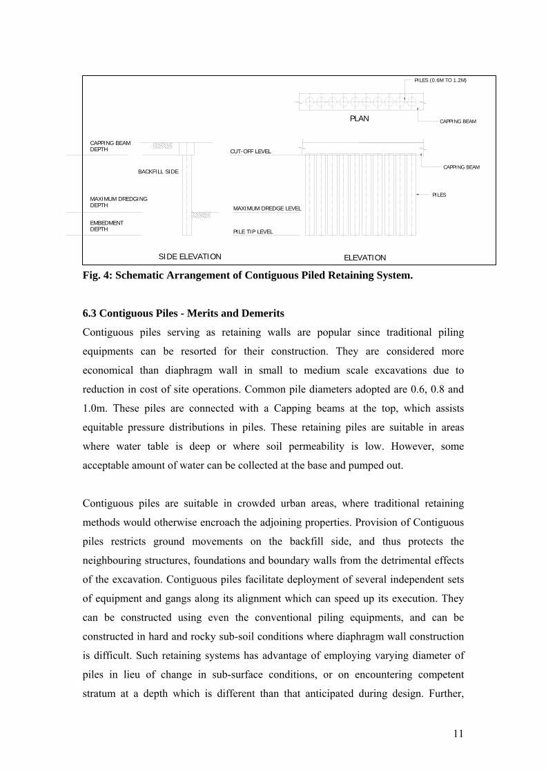
11
PLAN
PILES (0.6M TO 1.2M)
PILES
CAPPING BEAM
CAPPING BEAM
ELEVATION
CUT-OFF LEVEL
SIDE ELEVATION
MAXIMUM DREDGE LEVEL
PILE TIP LEVEL
BACKFILL SIDE
CAPPING BEAM DEPTH
MAXIMUM DREDGINGDEPTH
EMBEDMENT DEPTH
Fig. 4: Schematic Arrangement of Contiguous Piled Retaining System.
6.3 Contiguous Piles - Merits and Demerits
Contiguous piles serving as retaining walls are popular since traditional piling
equipments can be resorted for their construction. They are considered more
economical than diaphragm wall in small to medium scale excavations due to
reduction in cost of site operations. Common pile diameters adopted are 0.6, 0.8 and
1.0m. These piles are connected with a Capping beams at the top, which assists
equitable pressure distributions in piles. These retaining piles are suitable in areas
where water table is deep or where soil permeability is low. However, some
acceptable amount of water can be collected at the base and pumped out.
Contiguous piles are suitable in crowded urban areas, where traditional retaining
methods would otherwise encroach the adjoining properties. Provision of Contiguous
piles restricts ground movements on the backfill side, and thus protects the
neighbouring structures, foundations and boundary walls from the detrimental effects
of the excavation. Contiguous piles facilitate deployment of several independent sets
of equipment and gangs along its alignment which can speed up its execution. They
can be constructed using even the conventional piling equipments, and can be
constructed in hard and rocky sub-soil conditions where diaphragm wall construction
is difficult. Such retaining systems has advantage of employing varying diameter of
piles in lieu of change in sub-surface conditions, or on encountering competent
stratum at a depth which is different than that anticipated during design. Further,

12
unlike the diaphragm wall – which relies on the orthogonal geometry of the excavated
area – contiguous pile retaining system can constructed to form any shape in the
excavated area.
They are however, not considered suitable for construction in areas of high water
table, as retention and containing water is not possible in contiguous piles. Perfect
alignment of piles is often difficult to achieve at site, and this in turn is found to affect
the dimension and alignment of the Capping beams. In design parlance, only the
portion of concrete and steel away from the neutral axis is known to offer resisting
moment. As a result, some concrete and steel area remains under-utilized.
6.4 Case History – Contiguous Piling Works For a Commercial Complex at
Mumbai
A supporting system for proposed 12.2m deep excavation was necessary for a
commercial complex at Worli, Mumbai. Presence of existing footing, underground
obstructions and utilities in addition to presence of trees were some of the decisive
factors that eliminated choice of diaphragm wall.
Idealized sub-surface features can be seen in Fig. 5, which indicated filled ground
overlying Stiff clay and weathered Breccia formation. Presence of weathered
Brecciatic formation at 6m depth posed impediment to effective construction of the
diaphragm wall. Further, presence of neighbouring building and boundary wall at
immediate vicinity of excavation denied provision of anchors in any form of retaining
system. In this situation, the choice of retaining system rested on provision of
contiguous pile wall.
The remedial supporting provision comprised 1200mm diameter bored cast-in-situ
piles spaced at 1.3m c/c, with an average embedment depth of 3.8m in the moderately
weathered Breccia. These piles were designed as cantilever retaining system without
provision of anchors. Capping beam (1.2m x 0.75m deep) was provided above the
contiguous piles, which were designed to take care of differential changes in the earth
pressures in the adjacent piles. The peripheral length of excavation was 366.31m and
292 piles were involved in the support work.

13
Individual piles were constructed in the same way as a typical Bored Cast-in-situ piles
using temporary casings and bentonite slurry. General construction sequence for
piling operation was:
(i) Centering of rotary rig on the proposed pile point
(ii) Carrying out the boring operation upto the weathered rock layer, that is
upto about 6m below the established ground level
(iii) Driving the casing to an approximate depth of about 4m below the
ground
(iv) Maintaining the stability of the borehole simultaneously with
bentonite slurry
(v) Continuing boring operation in soil and rock using soil bucket and/or
Soil/Rock auger depending on the stratum
(vi) After completion of boring, cleaning of borehole by bentonite flushing
(vii) Lowering of rebar cage into the borehole
(viii) Repeat bentonite flushing operation and subsequently
(ix) Pouring concrete through tremie upto about 0.5m above the cut-off
level.
Fig. 5: Contiguous Pile Retaining System for Commercial a Complex at Worli,
Mumbai.
1.3 1.3
0.10
1200mm ØPILES
ARRANGEMENT OF CONTIGUOUS PILES
LAYOUT OF CONTIGUOUS PILES
RAMP
BASEMENT RETAINING WALL
FILL MATERIALC=0;Phi=15°Navg=5
FIRM TO STIFF HIGHLY PLASTICCLAY (CH)C=25kN/m²;Phi=0 ,Navg=10
COMPLETELY WEATHERED ROCKNavg=47
MODERATELY WEATHERED ROCK (UCS)avg=349.O kN/m³
MODERATELY WEATHERED ROCK (UCS)avg=786.0 kN/m³
EGL(0.0M)
3.0M
5.0M
1.0M
3.2M
EXCAVATION LEVEL
124.8M
50.6
05M
22.10
14.1
62
12.0M
35.10M
ALIGNMENT OFCONTIGUOUSPILES
BASEMENTRETAININGWALL
EXCAVATED PORTION
IDEALIZED SUB-SURFACE LOG
14
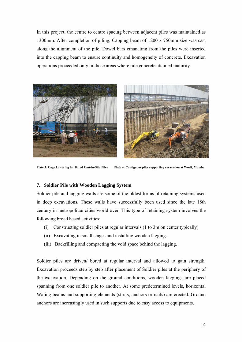
In this project, the centre to centre spacing between adjacent piles was maintained as
1300mm. After completion of piling, Capping beam of 1200 x 750mm size was cast
along the alignment of the pile. Dowel bars emanating from the piles were inserted
into the capping beam to ensure continuity and homogeneity of concrete. Excavation
operations proceeded only in those areas where pile concrete attained maturity.
Plate 3: Cage Lowering for Bored Cast-in-Situ Piles Plate 4: Contiguous piles supporting excavation at Worli, Mumbai
7. Soldier Pile with Wooden Lagging System
Soldier pile and lagging walls are some of the oldest forms of retaining systems used
in deep excavations. These walls have successfully been used since the late 18th
century in metropolitan cities world over. This type of retaining system involves the
following broad based activities:
(i) Constructing soldier piles at regular intervals (1 to 3m on center typically)
(ii) Excavating in small stages and installing wooden lagging.
(iii) Backfilling and compacting the void space behind the lagging.
Soldier piles are driven/ bored at regular interval and allowed to gain strength.
Excavation proceeds step by step after placement of Soldier piles at the periphery of
the excavation. Depending on the ground conditions, wooden laggings are placed
spanning from one soldier pile to another. At some predetermined levels, horizontal
Waling beams and supporting elements (struts, anchors or nails) are erected. Ground
anchors are increasingly used in such supports due to easy access to equipments.

15
LAGGINGOODEN ELEMENTS)
SOLDIER PILES(STEEL H- SECTION)
EXCAVATED PORTION
80M
2 TO 3M
Moment resistance in soldier pile and lagging walls is provided solely by the soldier
piles. Passive soil resistance is obtained by embedding the soldier piles beneath the
excavation grade. The lagging bridges and retains soil across piles and transfers the
lateral load to the soldier pile system.
Fig. 6: Soldier Pile and Wooden Lagging System
7.2 Merits and Demerits
Soldier pile and lagging walls are the most inexpensive systems compared to other
retaining walls. They are also very easy and fast to construct. These are found to be
suitable for soils with some cohesion and without water table. They are commonly
preferred in narrow excavations for pipe laying or similar works, but are also used for
deep and large excavations in conjunction with struts.
The major disadvantages of soldier pile and lagging systems are that they are
primarily limited to temporary construction. They cannot be used in high water table
conditions without extensive dewatering. Poor backfilling and associated ground
losses can result in significant surface settlements. They are not as rigid as other
retaining systems. Because only the flange of a soldier pile is embedded beneath
subgrade, it is very difficult to control basal soil movements.
16
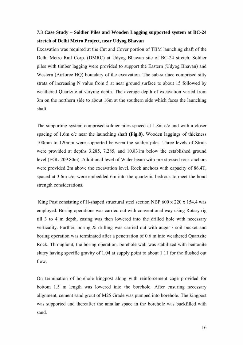
7.3 Case Study – Soldier Piles and Wooden Lagging supported system at BC-24
stretch of Delhi Metro Project, near Udyog Bhavan
Excavation was required at the Cut and Cover portion of TBM launching shaft of the
Delhi Metro Rail Corp. (DMRC) at Udyog Bhawan site of BC-24 stretch. Soldier
piles with timber lagging were provided to support the Eastern (Udyog Bhavan) and
Western (Airforce HQ) boundary of the excavation. The sub-surface comprised silty
strata of increasing N value from 5 at near ground surface to about 15 followed by
weathered Quartzite at varying depth. The average depth of excavation varied from
3m on the northern side to about 16m at the southern side which faces the launching
shaft.
The supporting system comprised soldier piles spaced at 1.8m c/c and with a closer
spacing of 1.6m c/c near the launching shaft (Fig.8). Wooden laggings of thickness
100mm to 120mm were supported between the soldier piles. Three levels of Struts
were provided at depths 3.285, 7.285, and 10.831m below the established ground
level (EGL-209.80m). Additional level of Waler beam with pre-stressed rock anchors
were provided 2m above the excavation level. Rock anchors with capacity of 86.4T,
spaced at 3.6m c/c, were embedded 6m into the quartzitic bedrock to meet the bond
strength considerations.
King Post consisting of H-shaped structural steel section NBP 600 x 220 x 154.4 was
employed. Boring operations was carried out with conventional way using Rotary rig
till 3 to 4 m depth, casing was then lowered into the drilled hole with necessary
verticality. Further, boring & drilling was carried out with auger / soil bucket and
boring operation was terminated after a penetration of 0.6 m into weathered Quartzite
Rock. Throughout, the boring operation, borehole wall was stabilized with bentonite
slurry having specific gravity of 1.04 at supply point to about 1.11 for the flushed out
flow.
On termination of borehole kingpost along with reinforcement cage provided for
bottom 1.5 m length was lowered into the borehole. After ensuring necessary
alignment, cement sand grout of M25 Grade was pumped into borehole. The kingpost
was supported and thereafter the annular space in the borehole was backfilled with
sand.

17
Excavation of about 1.5 to 2.0 m was considered free standing for few hours and in
the ensuing period wooden laggings were inserted into the web portion of adjacent H
shaped soldier piles. Excavation operation was followed by insertion of lagging, and
was continued till the required excavation depth was achieved.
Fig. 8: Soldier Piles & Laggings Wooden Supporting System at Udyog Bhawan
of DMRC, New Delhi.
Plate 5: Soldier Piles and Wooden Lagging System at Udyog Bhawan, New Delhi
EXCAVATED FACE
SOIL FACE
EXCAVATED FACE
LAYOUT PLAN OF SOLDIER PILE
WOODENLAGGING
SOLDER PILEH-SHAPE STEEL
PRE BORE
SOIL FACE
EXCAVATED FACE
DETAILS OF WOODEN LAGGING
SLOPING RAMP
TOWARDS LAUNCHINGSHAFT LAGGING
SOLDER PILE
IDICATIVE TENTATIVEPOSITION OF ROCK ANCHOR(TYP)
0 1 2 7
2 8

18
8. SUMMARY AND CONCLUSIONS
In the forgoing sections, the retaining systems suitable in the urban environment were
outlined. Restrictions of space in the urban settings compel use of deep vertical
excavations, which require supports that are designed to consume minimum
construction space. Retaining systems like diaphragm wall, contiguous pile walls;
and soldier piles with wooden lagging described in this article has been successfully
used in India. Case studies of their use indicate that adequate quality control measures
and instrumentation monitoring of these systems go a long way in ensuring their safe
and economic deployment at site.
9. ACKNOWLEDGEMENTS
The authors express their gratitude to management and staff of ITD Cementation
India Limited, Mumbai, for encouragement and support in research and innovative
endeavours. Thanks are also to IGS Mumbai Chapter for providing august platform
for sharing their experiences.
10. REFERENCES
Clayton, C.R.I., Milititsky, J., Woods, R.I. (1993). Earth Pressure and Earth
Retaining Structures. Blackie Academic & Professional, London.
Teng, W.C. (1962). Foundation Design, Prentice Hall International.
Winterkon, H.F, Fang Hsai-Yang (1975). Foundation Engineering Handbook, Van
Nostrand Reinhold Company, New York.