italian european overseas - cofil
TRANSCRIPT

AGENTS
COLOMBO FILIPPETTI Torino S.r.l.Strada Comunale di None, 25I-10092 BEINASCO TOTel. 011 - 3972211Fax 011 - 3497863E-mail: [email protected]: http://www.cofilto.it
TECNOCAMME DI LOLLI LORELLAVia Panigale,11I-40132 BolognaTel. 051-6415568Fax 051-6419072E-mail: [email protected]
MARANGONIVia Monte Lozzo,9I-35031 ABANO TERME PDTel. 049-667833Fax 049-8668908E-mail: [email protected]
WIDE AUTOMATION SRLVia Malpasso,1340I-47842 S.GIOVANNI IN MARIGNANO RNTel. 0541-827200Fax 0541-825021E-mail: [email protected]: http://www.wideautomation.it
COLOMBO FILIPPETTI SPASUCCURSALE FRANCE
FranceBp 14-2 Rue de BâleF-68180 HORBOURG WIHR CEDEXTel. 0033 3 89216867Fax 0033 3 89216999E-mail: [email protected]
MIKSCH GMBHGermanyReutlinger Strasse 5D-73037 GÖPPINGENTel. 0049 7161 67240Fax 0049 7161 15482 (14429)E-mail: [email protected]: http://www.miksch.de
PRECISION MOTION (COFIL) LTDGreat BritainNORTHERN SALES OFFICEUnit 35 Roman Way Longridge RdUK-PRESTON LANCS PR.2 5BDTel. 0044 1772 653366Fax 0044 1772 653163E-mail: [email protected]
SITI IBERICA S.L.SpainC/Permanyer,34E-08205 SABADELL BarcellonaTel. 0034 93 745 19 50Fax 0034 93 725 50 79E-mail: [email protected]: http://www.sitiiberica.com
INDEXING TECHNOLOGIES INC.U.S.AP.O. BOX 252,37 Orchard St.RAMSEY, N.J. 07446-0252Tel. 001 201 934 6333Fax 001 201 934 6488E-mail: [email protected]: http://www.indexingtechnologies.com
INDEXING TECHNOLOGIES INC.
U.S.A.(MIDWEST OFFICE)9041 N.FIELDING ROADMILWAUKEE,WI 53217-1833 USATel. 001 414 352-6120Fax 001 414 352-6125E-mail: [email protected]: http://www.indexingtechnologies.com
DAE DONG F.A. CO.LTDSOUTH KOREA1055-12 DOKSAN-DONGKUMCHON-KU,SEOULTel. 0082 2 8071381-4Fax 0082 2 8071385E-mail: [email protected]
GEAREX CORPORATIONTAIWANNO.13, TA TUNG 1ST RD.,KUAN YIN IND,PARK,TAOYUAN HSIEN TAIPEITel. 00886 26322856Fax 00886 34831427E-mail: [email protected]
PRECISION INTERNATIONALINDIA108,Aashirwad,Green Park (Main)NEW DELHI-110016Tel. 0091 11 26561687Fax 0091 11 26851390E-mail: [email protected]: http://www.precinter.com
italian european overseas
VELOMAT SRLVia Rossini,26I-24040 CASIRATE D’ADDA BGTel. 800119701Tel. 335-7126044Fax 0363-325252E-mail: [email protected]: http://www.velomat.com
KINETIC (China) LimitedHONG KONGUnit A9-16F., Kailey Ind.Centre,BlockA, 12 Fung Yip StreetCHAI WANTel. 00852 25055818Fax 00852 25054260GuangzhouTel. 0086 020 81200224Fax 0086 020 81200224E-mail: [email protected]: http://www.kineticltd.com.hk
RDB COMMERCIALEStrada Comunale di None, 25I-10092 BEINASCO TOTel. 011-3989546Fax 011-3497863E-mail: [email protected]
VVVVVia Rossini, 26 I-24040 CASIRAia Rossini, 26 I-24040 CASIRAia Rossini, 26 I-24040 CASIRAia Rossini, 26 I-24040 CASIRAia Rossini, 26 I-24040 CASIRATE D’ADDA -BG -TTE D’ADDA -BG -TTE D’ADDA -BG -TTE D’ADDA -BG -TTE D’ADDA -BG -Tel 0363-3251 Fax 0363-325252el 0363-3251 Fax 0363-325252el 0363-3251 Fax 0363-325252el 0363-3251 Fax 0363-325252el 0363-3251 Fax 0363-325252http://wwwhttp://wwwhttp://wwwhttp://wwwhttp://www.cofil.it - E-mail [email protected] - E-mail [email protected] - E-mail [email protected] - E-mail [email protected] - E-mail [email protected]
CF1141 10-03
TECHNICAL INFORMATION,ADVICE ON APPLICATIONSAND DIMENSIONING
TECHNICAL INFORMATION
1
Contents PAG
1. Technical information ..........................................................2
2. Index drive applications........................................................4
3. Selection of system components. .........................................6
4. Engineering and calculations.................................................8
5. Tables.............................................................................10
6. Examples ........................................................................11
The units of measurement correspond with System International /Severity Index SI General tolerances of manufacture are conform to UNI – ISO 2768-1 UNI EN 22768- 1 Illustrations and drawings according to UNI 3970 (ISO 128-82). Method of projection of the drawings. All rights reserved. No part of this catalogue may be duplicated. COLOMBO FILIPPETTI may make any changes they feel necessary for the improvement of their products without advance notice. COLOMBO FILIPPETTI may change any market components and accessories mentioned in this catalogue as they feel necessary. This catalogue supersedes all earlier ones.

TECHNICAL INFORMATION
2
1.1 INTRODUCTION The INDEX DRIVES, RIGHT ANGLE INDEXING TABLES, OSCILLATING DRIVES and MANIPULATORS manufactured by COLOMBO FILIPPETTI are mechanisms which transform the constant speed rotary motion of the input shaft into intermittent one-way or oscillating movement of the output shaft by way of a cam drive with conjugate profiles and roller feelers. The features which make these mechanisms a high quality product are their simple structure, direct motion transmission, principles of motion with mathematically calculated acceleration tested in numerous applications, the use of modern design and manufacturing technologies, precise, ongoing checks of the parts during the production cycle, and long experience in the calculation, manufacture and application possibilities of cams. The following characteristics: • Precise, repeatable index motion • Self locking in dwell and zero backlash • Smooth and shock-free movement • High load capacity • Regular operation at low, medium and high speeds • Easy, versatile assembly • Low level of maintenance • Low running costs (low level of energy input) • Extensive range of models are such as to meet the requirements involved in any type of application.
1.2 - CAM MECHANISMS The high speeds and productivity rates required by every type of industry nowadays mean that components of intermittent one-way or oscillating motion machinery must be driven at gentle, continuous, absolutely precise acceleration and speed. The sistyems producing this type of motion must therefore guarantee control of the movement throughout the TRANSFER-PAUSE cycle. Cam mechanisms allow accurate design of motion characteristics and fully meet the above requirements. The production of intermittent motion by systems other than cam systems involves one or more of the following disadvantages: • Uncoltrolled acceleration • Dynamic shocks • High level of maintenance • Unknown time/transfer ratios • High running costs Even the Geneva mechanism has some of these limitations, and their use is consequently inadvisable today.
TECHNICAL INFORMATION
3
1.3 - DESIGN PRINCIPLES OF CAM MECHANISMS
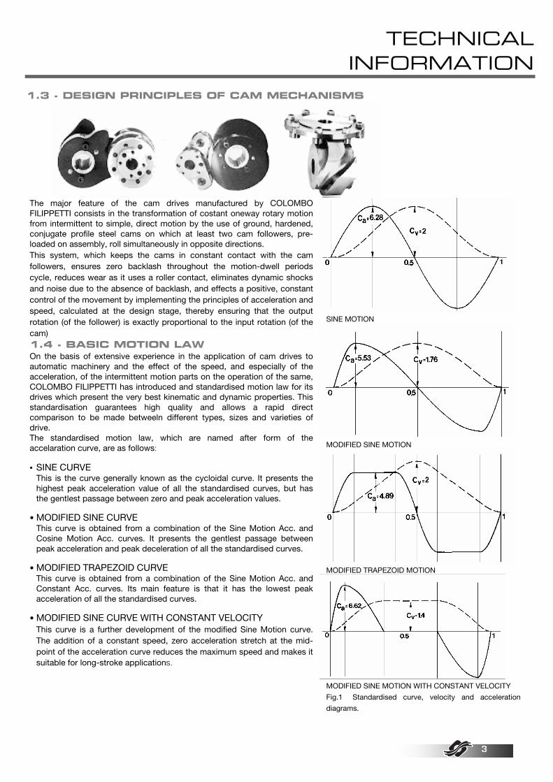
The major feature of the cam drives manufactured by COLOMBO FILIPPETTI consists in the transformation of costant oneway rotary motion from intermittent to simple, direct motion by the use of ground, hardened, conjugate profile steel cams on which at least two cam followers, pre-loaded on assembly, roll simultaneously in opposite directions. This system, which keeps the cams in constant contact with the cam followers, ensures zero backlash throughout the motion-dwell periods cycle, reduces wear as it uses a roller contact, eliminates dynamic shocks and noise due to the absence of backlash, and effects a positive, constant control of the movement by implementing the principles of acceleration and speed, calculated at the design stage, thereby ensuring that the output rotation (of the follower) is exactly proportional to the input rotation (of the cam) 1.4 - BASIC MOTION LAW On the basis of extensive experience in the application of cam drives to automatic machinery and the effect of the speed, and especially of the acceleration, of the intermittent motion parts on the operation of the same, COLOMBO FILIPPETTI has introduced and standardised motion law for its drives which present the very best kinematic and dynamic properties. This standardisation guarantees high quality and allows a rapid direct comparison to be made betweeln different types, sizes and varieties of drive. The standardised motion law, which are named after form of the accelaration curve, are as follows: • SINE CURVE This is the curve generally known as the cycloidal curve. It presents the
highest peak acceleration value of all the standardised curves, but has the gentlest passage between zero and peak acceleration values.
• MODIFIED SINE CURVE This curve is obtained from a combination of the Sine Motion Acc. and
Cosine Motion Acc. curves. It presents the gentlest passage between peak acceleration and peak deceleration of all the standardised curves.
• MODIFIED TRAPEZOID CURVE This curve is obtained from a combination of the Sine Motion Acc. and
Constant Acc. curves. Its main feature is that it has the lowest peak acceleration of all the standardised curves.
• MODIFIED SINE CURVE WITH CONSTANT VELOCITY This curve is a further development of the modified Sine Motion curve.
The addition of a constant speed, zero acceleration stretch at the mid-point of the acceleration curve reduces the maximum speed and makes it suitable for long-stroke applications.
SINE MOTION
MODIFIED SINE MOTION
MODIFIED TRAPEZOID MOTION
MODIFIED SINE MOTION WITH CONSTANT VELOCITY
Fig.1 Standardised curve, velocity and acceleration
diagrams.
INDEX DRIVE APPLICATIONS
TECHNICAL INFORMATION
4
Correct application of the CF3 INDEX DRIVES is strictly dependent on appropriate selection of all system components and knowledge of the distinctive features of the interior of the drive. This paragraph contains the relevant definitions and some approximate data, which should aid better use of the characteristics of these drives.
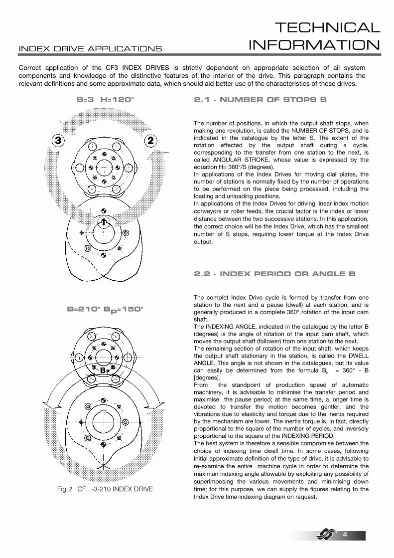
S=3 H=120°
B=210° BP=150°
Fig.2 CF...-3-210 INDEX DRIVE
2.1 - NUMBER OF STOPS S The number of positions, in which the output shaft stops, when making one revolution, is called the NUMBER OF STOPS, and is indicated in the catalogue by the letter S. The extent of the rotation effected by the output shaft during a cycle, corresponding to the transfer from one station to the next, is called ANGULAR STROKE, whose value is expressed by the equation H= 360°/S (degrees). In applications of the Index Drives for moving dial plates, the number of stations is normally fixed by the number of operations to be performed on the piece being processed, including the loading and unloading positions. In applications of the Index Drives for driving linear index motion conveyors or roller feeds, the crucial factor is the index or linear distance between the two successive stations. In this application, the correct choice will be the Index Drive, which has the smallest number of S stops, requiring lower torque at the Index Drive output. 2.2 - INDEX PERIOD OR ANGLE B The complet Index Drive cycle is formed by transfer from one station to the next and a pause (dwell) at each station, and is generally produced in a complete 360° rotation of the input cam shaft. The INDEXING ANGLE, indicated in the catalogue by the letter B (degrees) is the angle of rotation of the input cam shaft, which moves the output shaft (follower) from one station to the next. The remaining section of rotation of the input shaft, which keeps the output shaft stationary in the station, is called the DWELL ANGLE. This angle is not shown in the catalogues, but its value can easily be determined from the formula BP = 360° - B [degrees]. From the standpoint of production speed of automatic machinery, it is advisable to minimise the transfer period and maximise the pause period; at the same time, a longer time is devoted to transfer the motion becomes gentler, and the vibrations due to elasticity and torque due to the inertia required by the mechanism are lower. The inertia torque is, in fact, directly proportional to the square of the number of cycles, and inversely proportional to the square of the INDEXING PERIOD. The best system is therefore a sensible compromise between the choice of indexing time dwell time. In some cases, following initial approximate definition of the type of drive, it is advisable to re-examine the entire machine cycle in order to determine the maximun indexing angle allowable by exploiting any possibility of superimposing the various movements and minimising down time; for this purpose, we can supply the figures relating to the Index Drive time-indexing diagram on request.
INDEX DRIVE APPLICATIONS
TECHNICAL INFORMATION
5
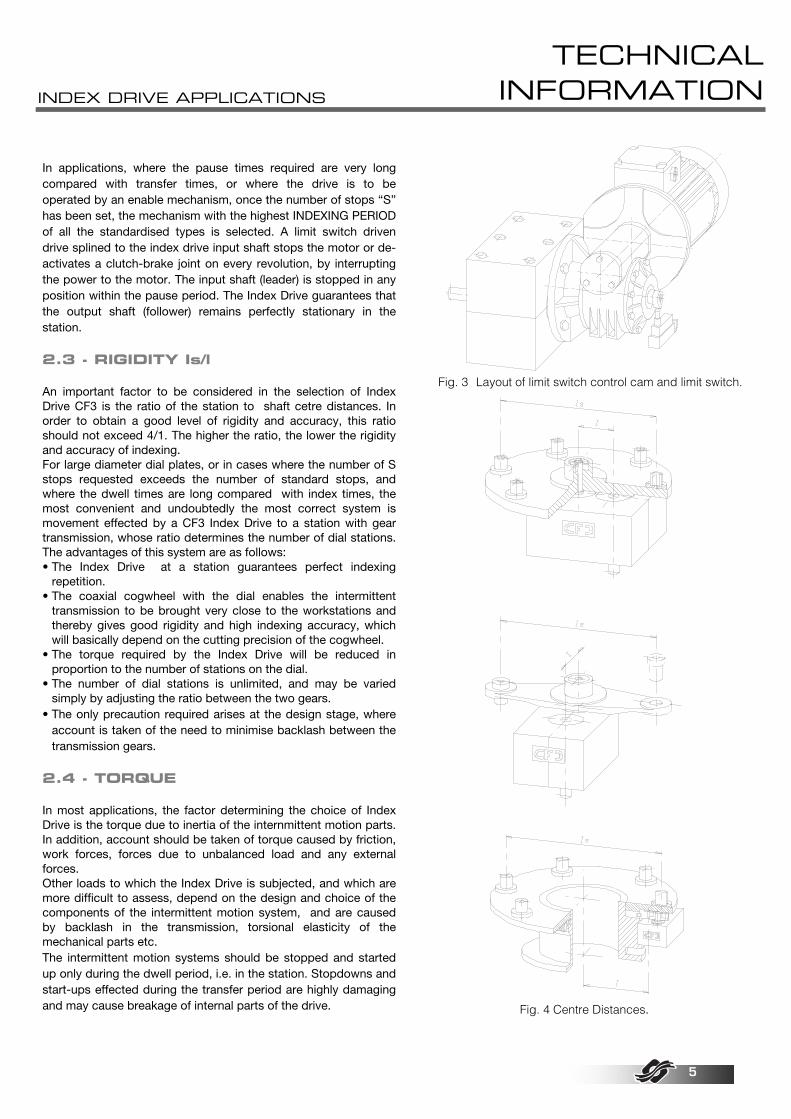
In applications, where the pause times required are very long compared with transfer times, or where the drive is to be operated by an enable mechanism, once the number of stops “S” has been set, the mechanism with the highest INDEXING PERIOD of all the standardised types is selected. A limit switch driven drive splined to the index drive input shaft stops the motor or de-activates a clutch-brake joint on every revolution, by interrupting the power to the motor. The input shaft (leader) is stopped in any position within the pause period. The Index Drive guarantees that the output shaft (follower) remains perfectly stationary in the station. 2.3 - RIGIDITY Is/l An important factor to be considered in the selection of Index Drive CF3 is the ratio of the station to shaft cetre distances. In order to obtain a good level of rigidity and accuracy, this ratio should not exceed 4/1. The higher the ratio, the lower the rigidity and accuracy of indexing. For large diameter dial plates, or in cases where the number of S stops requested exceeds the number of standard stops, and where the dwell times are long compared with index times, the most convenient and undoubtedly the most correct system is movement effected by a CF3 Index Drive to a station with gear transmission, whose ratio determines the number of dial stations. The advantages of this system are as follows: • The Index Drive at a station guarantees perfect indexing
repetition. • The coaxial cogwheel with the dial enables the intermittent
transmission to be brought very close to the workstations and thereby gives good rigidity and high indexing accuracy, which will basically depend on the cutting precision of the cogwheel.
• The torque required by the Index Drive will be reduced in proportion to the number of stations on the dial.
• The number of dial stations is unlimited, and may be varied simply by adjusting the ratio between the two gears.
• The only precaution required arises at the design stage, where account is taken of the need to minimise backlash between the transmission gears.
2.4 - TORQUE In most applications, the factor determining the choice of Index Drive is the torque due to inertia of the internmittent motion parts. In addition, account should be taken of torque caused by friction, work forces, forces due to unbalanced load and any external forces. Other loads to which the Index Drive is subjected, and which are more difficult to assess, depend on the design and choice of the components of the intermittent motion system, and are caused by backlash in the transmission, torsional elasticity of the mechanical parts etc. The intermittent motion systems should be stopped and started up only during the dwell period, i.e. in the station. Stopdowns and start-ups effected during the transfer period are highly damaging and may cause breakage of internal parts of the drive.
Fig. 3 Layout of limit switch control cam and limit switch.
Fig. 4 Centre Distances.

SELECTION OF SYSTEM COMPONENTNS
TECHNICAL INFORMATION
6
The moving parts of intermittent motion systems, unlike those of costant speed motors, must be accelerated from zero to maximum speed and vice versa during each cycle. In order to accelerate and decelerate their masses, the CF3 INDEX DRIVE has to exercise positive and negative torque alterntately, whose pattern is similar to that of the acceleration curve for the principle of motion used. This requires special attention to be given to the design of the input and output transmission parts (of the entire system) 3.1 - INPUT (CONTINUOUS) ELEMENTS
In addition to supplying energy to the INDEX DRIVE, the motor drive parts must guarantee that the input shaft rotates at a constant speed. This is necessary, because the variable strength torque required of the mechanisms producing intermittent motion tends to modify the rotation speed of the input shaft, causing it to pulsate during the indexing/dwell cycle. It is therefore preferable for the motor drive parts to be rigid, generously dimensioned and free of backlash. The best method of motorising an Index is the standard system comprising a worm gear reducer, preferably irreversible, directly splined to the input shaft, with minimum transmission backlash. This highly compact system enable
the rotationm speed to be stabilised as the worm gear reducer acts as a brake in the deceleration section of the cycle, dispersing through friction the kinetic energy restored to the input shaft by the intermittent motion system. Chain or belt gear transmission, speed variators, clutch/brake couplings or motors can be connected to the fast worm gear reducer shaft in a part of the drive system with low torque without giving rise to any particular transmission problems. If a worm gear reducer cannot be used, it is necessary in almost every application to spline a flywheel to the Index Drive input shaft in order to make the rotation speed as regular as possible. All parts rotating at costant speed, including the camshaft and the motor, contribute to supplying part the kinetic energy needed.
Fig. 5 Highly rigid, compact, direct motor drive.
transmission
Fig. 6 Rigid motor drive with transmission of fast worm gear reducer shaft.
rigid coupling
Fig. 7 Motor drive using connection with rigid coupling.
flywheel
Fig. 8 Motor drive using spring drive; the flywheel ensures that
the input shaft rotates at a constant speed.
SELECTION OF SYSTEM COMPONENTNS
TECHNICAL INFORMATION
7
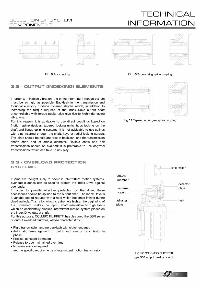
Fig. 9 Box coupling.
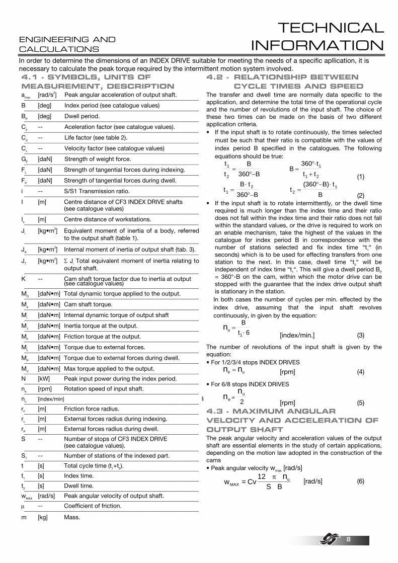
Fig.10 Tapered ring spline coupling. 3.2 - OUTPUT (INDEXING) ELEMENTS In order to minimise vibration, the entire intermittent motion system must be as rigid as possible. Backlash in the transmission and torsional elasticity produce dynamic shocks which, in addition to increasing the torque required of the Index Drive output shaft uncontrollably with torque peaks, also give rise to highly damaging vibrations. For this reason, it is advisable to use direct couplings based on friction spline devices, tapered locking units, hubs locking on the shaft and flange splining systems. It is not advisable to use splines with pins inserted through the shaft, keys or radial locking screws. The joints should be rigid and free of backlash, and the transmission shafts short and of ample diameter. Flexible chain and belt transmissions should be avoided; it is preferable to use cogwhel transmissions, which can take up any play. 3.3 - OVERLOAD PROTECTION SYSTEMS If jams are thought likely to occur in intermittent motion systems, overload clutches can be used to protect the Index Drive against overloads. In order to provide effective protection of the drive, these accessories should be splined to the output shaft. The Index Drive is a variable speed reducer with a ratio which becomes infinite during dwell periods. This ratio, which is extremely high at the beginning of the movement, makes the input shaft insensitive to high loads which an accidentally blocked intermittent motion system places on the Index Drive output shaft. For this purpose, COLMBO FILIPPETTI has designed the GSR series of output overload clutches, whose characteristics: • Rigid transmission and no backlash with clutch engaged • Automatic re-engagement of clutch and reset of transmission in
phase • Precise, constant operation • Release torque maintained over time • No maintenance required meet the specific requirements of intermittent motion transmission.
Fig.11 Tapered screw gear spline coupling.
drivenmember
externalcasing
adjusterplate
limit switch
hub
detectorplate
Fig.12 COLOMBO FILIPPETTI
type GSR output overload clutch.
ENGINEERING AND CALCULATIONS
TECHNICAL INFORMATION
8
In order to determine the dimensions of an INDEX DRIVE suitable for meeting the needs of a specific apllication, it is necessary to calculate the peak torque required by the intermittent motion system involved. 4.1 - SYMBOLS, UNITS OF MEASUREMENT, DESCRIPTION amax [rad/s2] Peak angular acceleration of output shaft. __________________________________________________________B [deg] Index period (see catalogue values) __________________________________________________________BP [deg] Dwell period. __________________________________________________________Ca -- Aceleration factor (see catalogue values). __________________________________________________________Cd -- Life factor (see table 2). __________________________________________________________Cv -- Velocity factor (see catalogue values) __________________________________________________________GF [daN] Strength of weight force. __________________________________________________________FL [daN] Strength of tangential forces during indexing. __________________________________________________________FP [daN] Strength of tangential forces during dwell. __________________________________________________________i -- S/S1 Transmission ratio. __________________________________________________________I [m] Centre distance of CF3 INDEX DRIVE shafts (see catalogue values) __________________________________________________________Is [m] Centre distance of workstations. __________________________________________________________Ji [kg•m2] Equivalent moment of inertia of a body, referred
to the output shaft (table 1). __________________________________________________________JA [kg•m2] Internal moment of inertia of output shaft (tab. 3). __________________________________________________________JT [kg•m2] Σ Ji Total equivalent moment of inertia relating to
output shaft. __________________________________________________________K -- Cam shaft torque factor due to inertia at output (see catalogue values) __________________________________________________________MD [daN•m] Total dynamic torque applied to the output. __________________________________________________________Me [daN•m] Cam shaft torque. __________________________________________________________Mi [daN•m] Internal dynamic torque of output shaft __________________________________________________________MJ [daN•m] Inertia torque at the output. __________________________________________________________MF [daN•m] Friction torque at the output. __________________________________________________________ML [daN•m] Torque due to external forces. __________________________________________________________MP [daN•m] Torque due to external forces during dwell. __________________________________________________________MV [daN•m] Max torque applied to the output. __________________________________________________________N [kW] Peak input power during the index period. __________________________________________________________ne [rpm] Rotation speed of input shaft. __________________________________________________________nu [index/min] In__________________________________________________________rF [m] Friction force radius. __________________________________________________________rL [m] External forces radius during indexing. __________________________________________________________rP [m] External forces radius during dwell. __________________________________________________________S -- Number of stops of CF3 INDEX DRIVE (see catalogue values). __________________________________________________________S1 -- Number of stations of the indexed part. __________________________________________________________t [s] Total cycle time (t1+t2). __________________________________________________________t1 [s] Index time. __________________________________________________________t2 [s] Dwell time. __________________________________________________________wMAX [rad/s] Peak angular velocity of output shaft. __________________________________________________________µ -- Coefficient of friction. __________________________________________________________m [kg] Mass.
4.2 - RELATIONSHIP BETWEEN CYCLE TIMES AND SPEED The transfer and dwell time are normally data specific to the application, and determine the total time of the operational cycle and the number of revolutions of the input shaft. The choice of these two times can be made on the basis of two different application criteria. • If the input shaft is to rotate continuously, the times selected
must be such that their ratio is compatible with the values of index period B specified in the catalogues. The following equations should be true:
tt
B360 B
1
2
=°−
B360 tt t
1
1 2=
°⋅
+ (1)
t
B t360 B1
2=⋅
°− t
(360 B) tB2
1=°− ⋅
(2) • If the input shaft is to rotate intermittently, or the dwell time
required is much longer than the index time and their ratio does not fall within the index time and their ratio does not fall within the standard values, or the drive is required to work on an enable mechanism, take the highest of the values in the catalogue for index period B in correspondence with the number of stations selected and fix index time “t1“ (in seconds) which is to be used for effecting transfers from one station to the next. In this case, dwell time “t2“ will be independent of index time “t1“. This will give a dwell period BP = 360°-B on the cam, within which the motor drive can be stopped with the guarantee that the index drive output shaft is stationary in the station. In both cases the number of cycles per min. effected by the index drive, assuming that the input shaft revolves continuously, in given by the equation:
nu
1
Bt 6
=⋅ [index/min.] (3)
The number of revolutions of the input shaft is given by the equation: • For 1/2/3/4 stops INDEX DRIVES
n ne u= [rpm] (4)
• For 6/8 stops INDEX DRIVES
n n
eu
2=
[rpm] (5) 4.3 - MAXIMUM ANGULAR VELOCITY AND ACCELERATION OF OUTPUT SHAFT The peak angular velocity and acceleration values of the output shaft are essential elements in the study of certain applications, depending on the motion law adopted in the construction of the cams • Peak angular velocity wmax [rad/s]
BS
12Cv=w u
MAX
nπ [rad/s] (6)

ENGINEERING AND CALCULATIONS
TECHNICAL INFORMATION
9
• Peak angular acceleration amax [rad/s2]
2
2u
MAX BS72
Ca=anπ
[rad/s2] (7)
4.4 - INERTIA TORQUE MJ
This in the torque required to accelerate and decelerate the intermittent motion parts of the system, and is generally the element determining the dimensioning of the index drive.
M J Ca
0.628S tJ T
12= ⋅ ⋅
⋅ [daN⋅m] (8) NB: Some example of calculations of the momentum of inertia of mass J [kg. m2] are set out in Table 1. 4.5 - FRICTION TORQUE MF
This is the torque necessary to overcome the frictional forces of the intermittent motion system, and depends on the mass, radius and coefficient of friction of the support.
i••r•G=M FFF µ [daN⋅m] (9)
4.6 - EXTERNAL FORCES TORQUE ML
This torque is present only in certain applications. It is due to external forces occurring or applied during the transfer period, such as: • Unbalanced loads moved in opposition to the force of gravity. • Applications in which the peices have to overcome air or other resistence. • Forces due to processing or opposing resistance of springs etc. In general, ML comprises all torque present in the intermittent motion system other than MJ and MF.
M F r iL L L= ⋅ ⋅ [daN⋅m] (10) 4.7 - TOTAL DYNAMIC TORQUE MD This is the sum of all dynamic torque previously calculated and required by the intermittent motion system.
M M M MD J F L= + + +.. . [daN⋅m] (11) 4.8 - TORQUE DURING DWELL MP In some applications, the mass of unbalanced loads or work forces applied during the dwell period cause torque, which the INDEX DRIVE output shaft has to withstand while stationary in the station
M F r iP P P= ⋅ ⋅ [daN⋅m] (12)
4.9 - OUTPUT TORQUE REQUIREMENT AND SELECT INDEX DRIVE Once the values of dynamic torque MD and dwell torque MP have been calculated, as these act in different periods of the cycle, in order to determine the size of the INDEX DRIVE it is necessary to take the higher of the torques, which will be indicated as MV.
M max(M ;M )V D P= [daN⋅m] (13)Output torque Mu ar various speeds (index/min.) applicable to the INDEX DRIVES and shown in the specification tables in the catalogues, takes account of an actual life of 8000 hours. It is therefore necessary to select and INDEX DRIVE which meets the following condition:
Mu Mv Cd≥ ⋅ [daN⋅m] (14)Static torque Ms [daN.m] shown in the specification tables in the catalogues is the limit torque which can be applied to the INDEX DRIVE output shaft in the pause stretch with the drive shut down without subsequently prejudicing the operation of the INDEX DRIVE. A further check, which should be made, when the CF3 INDEX DRIVE is to splined directly to the intermittent shaft of the machine, is the ratio betweel the diameter, on which the stations are applied and the centre distance between the shafts of the CF3 INDEX DRIVE. The maximum value advisable for general applications is:
IsI
4≤
(15) if this ratio is increased, the rigidity of the transmission and indexing accuracy decrease proportionally. 4.10 - PEAK INPUT TORQUE REQUIREMENT Me This is the nominal peak torque to be supplied to the input shaft in order to overcome torque MD required on output by the dynamic loads, including the inertial torque of the INDEX DRIVE output shaft, given by the equation:
Mi J C
0.628S tA a
12= ⋅ ⋅
⋅ [daN⋅m] (16)The input torque must be used to dimension all input parts, and any torque deriving from other loads applied to the INDEX DRIVE input shaft must be added.
Me (M Mi) K360S B
Cv (M M )J F L= + ⋅ +⋅
⋅ ⋅ + [daN⋅m]
(17) 4.11 - POWER REQUIRED N This is the power required to drive the mechanism. The INDEX DRIVES require maximun power only during the acceleration stretch of the cycle; during deceleration the energy is supplied by the motor drive. In practice, the power needed to drive the intermittent motion system is often lower than, and may be as little as half of the peak power, which is calculated by the following equations. It is essential for the motor drive to have a sufficient flywheel effect to prevent excessive fluctuations in speed during the transfer period.
N
Me974
ne=⋅
[kW] (18)

TABLES
TECHNICAL INFORMATION
10
TABLE 1 Some examples of Momentum of inertia of mass J [Kg·m2]
Cylinder or disc rotating about its own axis.
Jm2
R2= ⋅
Cylinder or disc rotating about an offset parallel axis.
Jm2
(R 2 I )2 2= ⋅ +
Hollow cylinder or ring rotating about its own axis.
Jm2
R r )2 2= ⋅ +(
Hollow cylinder or ring rotating about an offset parallel axis.
Jm2
(R r + 2 I )2 2 2= ⋅ +
Cylinder rotating about its diameters
Jm4
(C3
R )2
2= ⋅ +
Cylinder rotating about an offset axis parallel to its diameter..
Jm4
(C3
R 4 I )2
2 2= ⋅ + +
Hollow cylinder rotating about its diameter.
Jm4
(C3
R +r )2
2 2= ⋅ +
Hollow cylinder rotating about an offset axis parallel to its diameter.
Jm4
(C3
R r 4 I )2
2 2 2= ⋅ + + +
Parallelepiped or plate rotating about its own axis.
Jm12
(a b )2 2= ⋅ +
Parallelepiped rotating about an offset parallel axis.
Jm12
(a b +12 I )2 2 2= ⋅ +
Hollow parallelepiped or plate rotating about its own axis.
Jm12
(a b + a +b )2 212
12= ⋅ +
Hollow parallelepiped or plate rotating about offset parallel axis.
Jm12
(a a +b +b +12 I )212 2
12 2= ⋅ +
Mass considered concentrated on a circum-ference. J m R2= ⋅
Mass considered concentrated on a point. J m I2= ⋅
Notes: The momentum of inertia of the INDEX DRIVE input shaft it obtained from the equation Ji=J·i2 where i is the transmission ratio between the Index Drive output shaft and the axis of inertia examined. • Masses are expressed in [Kg] • Lengths are expressed in [m].
TABLE N° 2 life coefficients Required life [h] 8.000 12.000 16.000 20.000 30.000 40.000 60.000 80.000 Life coefficient Cd 1.00 1.13 1.23 1.32 1.49 1.62 1.83 2.00
TABLE N° 3 Momentum of inertia of output shaft JA [Kg·m2] Series 65P 80P 105P 130P 165P 200P 250P 315P CF3 Index Drive Stations 1 - 3 - 6
0.0003218 0.0011164 0.0038828 0.0134711 0.0364932 0.0909681 0.2409218 1.0243406
CF3 Index Drive Stations 2 - 4 - 8
0.0003473 0.0012007 0.0042222 0.0144756 0.0395539 0.0976193 0.2580815 1.0777462
CF3 Oscillating drive Strokes 15 - 20 - 30 - 45
0.0002158 0.0009123 0.00413 0.0103496 0.0345995 0.0986003 0.295065 1.2272114

EXAMPLES
TECHNICAL INFORMATION
11
EXAMPLE 1 DIAL PLATE DRIVE Data: Number of stops S=6 -- Index time t1=0.21 [s] Dwell time t2=0.29 [s] Dial plate diameter Dt=0.5 [m] Dial plate mass mt=31 [Kg] Radius of workstations Rs=0.2 [m] Mass of each piece holder mo=1 [Kg] Mass of each piece mz=3 [Kg] Friction force GF=55 [daN] Friction force radius rF=0.1 [m] Coefficient of friction µ=0.03 -- External forces during indexing FL=-- [daN] External forces radius rL=-- [m] Tangential forces during dwell Fp=70 [daN] Tangential forces radius rp=0.2 [m] Life required in hours T=16000 [h]
Indexing period B=(360⋅t1)/(t1+t2) =150 [deg] Dwell period Bp=360-B =210 [deg] Speed of output shaft nu=B/(6⋅t1) =120 [index/min.] Speed of input shaft ne=nu/2 =60 [RPM]
The INDEX DRIVE required is a CF3 ... P-6-150. The following coefficients can be obtained from the catalogue: CV=1.40 Ca=6.62 K=0.63
Total momentum of inertia of index drive output shaft in intermittent motion system 1 - Dial plate J1=mt⋅Dt2/8 =0.969 [Kg⋅m2] 2 - Piece holder J2=S⋅mO⋅Rs2 =0.240 [Kg⋅m2] 3 - Pieces J3=S⋅mZ⋅Rs2 =0.720 [Kg⋅m2] Total momentum of inertia JT=J1+J2+J3 =1.929 [Kg⋅m2]
Total dynamic torque 1 - Inertia MJ=JT⋅Ca⋅0.628/(S⋅t1
2) = 30.308 [daN⋅m] 2 - Friction MF=GF⋅rF⋅µ = 0.165 [daN⋅m] 3 - External forces ML=FL⋅rL = - - - [daN⋅m] Total dynamic torque MD=MJ+MF+ML = 30.473 [daN⋅m]
Torque during dwell Mp=Fp⋅rp = 14.000 [daN⋅m]
Maximum system torque MV = Max (MD;Mp)⋅Cd =37.5 [daN⋅m]
The CF3 INDEX DRIVE which meets the condition Mu > MV at 120 [index/min.] is the:
CF3 130P-6-150
Internal dynamic torque MI=JA⋅Ca⋅0.628/(S⋅ t12) =0.212 [daN⋅m]
Input torque Me=(MJ+MI)⋅K+360⋅CV⋅(MF+ML)/(S⋅B) =19.32 [daN⋅m]
Peak power required P=Me⋅ne/974 =1.19 [kW]
EXAMPLES
TECHNICAL INFORMATION
12
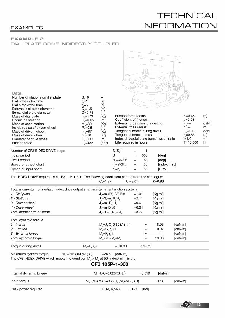
EXAMPLE 2 DIAL PLATE DRIVE INDIRECTLY COUPLED
Data: Number of stations on dial plate S1=6 -- Dial plate index time t1=1 [s] Dial plate dwell time t2=5 [s] External dial plate diameter De=1.5 [m] Iternal dial plate diameter Di=0.75 [m] Mass of dial plate mt=173 [Kg] Radius os stations RS=0.65 [m] Mass of each station mS=30 [Kg] Inertia radius of driven wheel RC=0.5 [m] Mass of driven wheel mC=87 [Kg] Mass of drive wheel mr=10 [Kg] Diameter of drive wheel Dr=0.17 [m] Friction force GF=432 [daN]
Friction force radius rF=0.45 [m] Coefficient of friction µ=0.03 -- External forces during indexing FL=-- [daN] External frces radius rL=-- [m] Tangential forces during dwell Fp=100 [daN] Tangential forces radius rp=0.65 [m] Index drive/dial plate transmission ratio i=1/6 -- Life required in hours T=16.000 [h]
Number of CF3 INDEX DRIVE stops S=S1⋅i = 1 Index period B = 300 [deg] Dwell period Bp=360-B = 60 [deg] Speed of output shaft nu=B/(6⋅t1) = 50 [index/min.] Speed of input shaft ne=nu = 50 [RPM]
The INDEX DRIVE required is a CF3 ... P-1-300. The following coefficient can be from the catalogue: CV=1.27 Ca=8.01 K=0.86
Total momentum of inertia of index drive output shaft in intermittent motion system 1 - Dial plate J1=mt⋅(De
2-Di
2)⋅i2/8 =1.01 [Kg⋅m2] 2 - Stations J2=S1⋅mS⋅RS
2⋅i2 =2.11 [Kg⋅m2] 3 - Driven wheel J3=mC⋅RC
2⋅ i2 =0.6 [Kg⋅m2] 4 - Drive wheel J4=mr⋅Dr
2/8 =0.04 [Kg⋅m2] Total momentum of inertia JT=J1+J2+J3+ J4 =3.77 [Kg⋅m2]
Total dynamic torque 1 - Inertia MJ=JT⋅Ca⋅0.628/(S⋅t1
2) = 18.96 [daN⋅m] 2 - Friction MF=GF⋅rF⋅µ⋅i = 0.97 [daN⋅m] 3 - External forces ML=FL⋅rL⋅i = - - - [daN⋅m] Total dynamic torque MD=MJ+MF+ML = 19.93 [daN⋅m]
Torque during dwell Mp=Fp⋅rp⋅i = 10.83 [daN⋅m]
Maximum system torque MV = Max (MD;Mp)⋅Cd =24.5 [daN⋅m] The CF3 INDEX DRIVE which meets the condition Mu > MV at 50 [index/min.] is the:
CF3 105P-1-300
Internal dynamic torque MI=JA⋅Ca⋅0.628/(S⋅ t1
2) =0.019 [daN⋅m]
Input torque Me=(MJ+MI)⋅K+360⋅CV⋅(MF+ML)/(S⋅B) =17.8 [daN⋅m]
Peak power required P=Me⋅ne/974 =0.91 [kW]
EXAMPLES
TECHNICAL INFORMATION
13
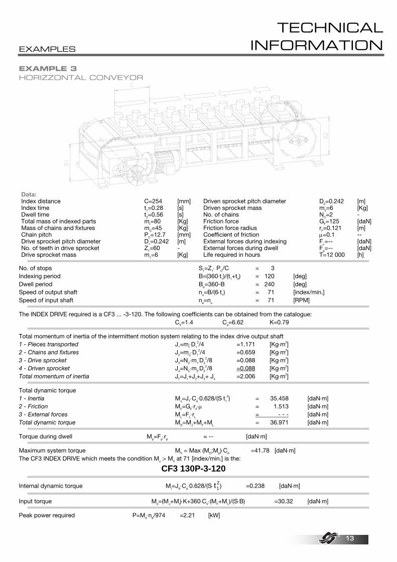
EXAMPLE 3 HORIZZONTAL CONVEYOR
Data: Index distance C=254 [mm] Index time t1=0.28 [s] Dwell time t2=0.56 [s] Total mass of indexed parts mt=80 [Kg] Mass of chains and fixtures mC=45 [Kg] Chain pitch PC=12.7 [mm] Drive sprocket pitch diameter D1=0.242 [m] No. of teeth in drive sprocket Z1=60 - Drive sprocket mass m1=6 [Kg]
Driven sprocket pitch diameter D2=0.242 [m] Driven sprocket mass m2=6 [Kg] No. of chains NC=2 - Friction force GF=125 [daN] Friction force radius rF=0.121 [m] Coefficient of friction µ=0.1 -- External forces during indexing FL=-- [daN] External forces during dwell Fp=-- [daN] Life required in hours T=12 000 [h]
No. of stops S1=Z1⋅ PC/C = 3 Indexing period B=(360⋅t1)/(t1+t2) = 120 [deg] Dwell period Bp=360-B = 240 [deg] Speed of output shaft nu=B/(6⋅t1) = 71 [index/min.] Speed of input shaft ne=nu = 71 [RPM]
The INDEX DRIVE required is a CF3 ... -3-120. The following coefficients can be obtained from the catalogue: CV=1.4 Ca=6.62 K=0.79
Total momentum of inertia of the intermittent motion system relating to the index drive output shaft 1 - Pieces transported J1=mt⋅D1
2/4 =1.171 [Kg⋅m2] 2 - Chains and fixtures J2=mC⋅D1
2/4 =0.659 [Kg⋅m2] 3 - Drive sprocket J3=NC⋅m1⋅D2
2/8 =0.088 [Kg⋅m2] 4 - Driven sprocket J4=NC⋅m2⋅D2
2/8 =0.088 [Kg⋅m2] Total momentum of inertia JT=J1+J2+J3+ J4 =2.006 [Kg⋅m2]
Total dynamic torque 1 - Inertia MJ=JT⋅Ca⋅0.628/(S⋅t1
2) = 35.458 [daN⋅m] 2 - Friction MF=GF⋅rF⋅µ = 1.513 [daN⋅m] 3 - External forces ML=FL⋅rL = - - - [daN⋅m] Total dynamic torque MD=MJ+MF+ML = 36.971 [daN⋅m]
Torque during dwell Mp=Fp⋅rp = -- [daN⋅m]
Maximum system torque MV = Max (MD;Mp)⋅Cd =41.78 [daN⋅m] The CF3 INDEX DRIVE which meets the condition Mu > MV at 71 [index/min.] is the:
CF3 130P-3-120
Internal dynamic torque MI=JA⋅Ca⋅0.628/(S⋅ t12) =0.238 [daN⋅m]
Input torque Me=(MJ+MI)⋅K+360⋅CV⋅(MF+ML)/(S⋅B) =30.32 [daN⋅m]
Peak power required P=Me⋅ne/974 =2.21 [kW]
EXAMPLES
TECHNICAL INFORMATION
14
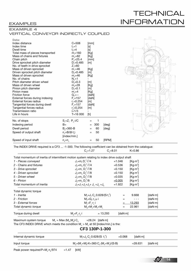
EXAMPLE 4 VERTICAL CONVEYOR INDIRECTLY COUPLED
Data: Index distance C=508 [mm] Index time t1=1 [s] Dwell time t2=4 [s] Total mass of pieces transported mt=160 [Kg] Mass of chains and fixtures mC=82 [Kg] Chain pitch PC=25.4 [mm] Drive sprocket pitch diameter D1=0.485 [m] No. of teeth in drive sprocket Z1=60 - Mass of driven sprocket m1=46 [Kg] Driven sprocket pitch diameter D2=0.485 [m] Mass of driven sprocket m2=46 [Kg] No. of chains NC=1 - Pitch diameter driven wheel D3=0.3 [m] Mass of driven wheel m3=28 [Kg] Pinion pitch diameter D4=0.1 [m] Pinion mass m4=4 [Kg] Friction force GF=-- [daN] External forces during indexing FL=157 [daN] External forces radius rL=0.254 [m] Tangential forces during dwell Fp=157 [daN] Tangential forces radius rp=0.254 [m] Transmission ratio i=1/3 - Life in hours T=16 000 [h] No. of stops S1=Z1⋅ PC⋅i/C = 1 Indexing period B= = 300 [deg] Dwell period Bp=360-B = 60 [deg] Speed of output shaft nu=B/(6⋅t1) = 50
[index/min.] Speed of input shaft ne=nu = 50 [RPM]
The INDEX DRIVE required is a CF3 ... -1-300. The following coefficient can be obtained from the catalogue:
CV=1.27 Ca=8.01 K=0.86
Total momentum of inertia of intermittent motion system relating to index drive output shaft 1 - Pieces conveyed J1=mt⋅D1
2⋅i2/4 =1.046 [Kg⋅m2] 2 - Chains and fixtures J2=mC⋅D1
2⋅i2/4 =0.536 [Kg⋅m2] 3 - Drive sprocket J3=m1 ⋅D1
2⋅i2/8 =0.150 [Kg⋅m2] 4 - Driven sprocket J4=m2 ⋅D2
2⋅i2/8 =0.150 [Kg⋅m2] 5 - Driven wheel J5=m3 ⋅D3
2⋅i2/8 =0.035 [Kg⋅m2] 6 - Pinion J6=m4 ⋅D4
2/8 =0.005 [Kg⋅m2] Total momentum of inertia JT=J1+J2+J3+ J4 +J5 +J6 =1.922 [Kg⋅m2]
Total dynamic torque 1 - Inertia MJ=JT⋅Ca⋅0.628/(S⋅t1
2) = 9.668 [daN⋅m] 2 - Friction MF=GF⋅rF⋅µ⋅i = - - - [daN⋅m] 3 - External forces ML=FL⋅rL⋅i = 13.293 [daN⋅m] Total dynamic torque MD=MJ+MF+ML = 22.961 [daN⋅m]
Torque during dwell Mp=Fp⋅rp⋅i = 13.293 [daN⋅m]
Maximum system torque MV = Max (MD;Mp)⋅Cd =28.24 [daN⋅m] The CF3 INDEX DRIVE which meets the condition Mu > MV at 50 [index/min.] is the:
CF3 130P-1-300
Internal dynamic torque MI=JA⋅Ca⋅0.628/(S⋅ t1
2) =0.068 [daN⋅m]
Input torque Me=(MJ+MI)⋅K+360⋅CV⋅(MF+ML)/(S⋅B) =28.631 [daN⋅m]
Peak power required P=Me⋅ne/974 =1.47 [kW]

EXAMPLES
TECHNICAL INFORMATION
15
EXAMPLE 5 HORIZONTAL AXIS TURNOVER DEVICE
Data: No. of stops S=2 - Indexing time t1=1 [s] Dwell ime t2=1 [s] Length of turnover arm a=0.75 [m] Width of turnover arm b=0.1 [m] Total mass of turnover arm m2=50 [Kg] Shaft diameter Da=0.15 [m]
Shaft mass ma=40 [Kg] Radius of inertia of pieces R1=0.275 [m] Mass of pieces m1=80 [Kg] Friction force GF=-- [daN] External forces during transfer FL=78.5 [daN] External forces radius rL=0.275 [m] Life required in hours T=8 000 [h]
Index period B=(360⋅t1)/(t1+t2) = 180 [deg] Dwell period Bp=360-B = 180 [deg] Speed of output shaft nu=B/(6⋅t1) = 30 [index/min.] Speed of input shaft ne=nu = 30 [RPM]
The INDEX DRIVE required is a CF3 ... -2-180. The following coefficients can be obtained from the catalogue: CV=1.4 Ca=6.62 K=0.79
Total momentum of inertia of intermittent motion system relating to index drive output shaft 1 - Pieces J1=m1⋅R1
2 =6.05 [Kg⋅m2] 2 - Turnover arm J2=m2⋅(a
2+b2)/12 =2.38 [Kg⋅m2]
3 - Turnover shaft J3=ma ⋅Da2 /8 =0.11 [Kg⋅m2]
Total momentum of inertia JT=J1+J2+J3 =8.54 [Kg⋅m2]
Total dynamic torque 1 - Inertia MJ=JT⋅Ca⋅0.628/(S⋅t1
2) = 17.75 [daN⋅m] 2 - Friction MF=GF⋅rF⋅µ = - - - [daN⋅m] 3 - External forces ML=FL⋅rL = 21.60 [daN⋅m] Total dynamic torque MD=MJ+MF+ML = 39.35 [daN⋅m]
Torque during dwell Mp=Fp⋅rp = -- [daN⋅m]
Maximum system torque MV = Max (MD;Mp)⋅Cd =39.35 [daN⋅m] The CF3 INDEX DRIVE which meets the condition Mu > MV at 30 [index/min.] is the:
CF3 130P-2-180
Internal dynamic torque MI=JA⋅Ca⋅0.628/(S⋅ t1
2) =0.03 [daN⋅m]
Input torque Me=(MJ+MI)⋅K+360⋅CV⋅(MF+ML)/(S⋅B) =44.286 [daN⋅m]
Peak power required P=Me⋅ne/974 =1.36 [kW]
EXAMPLES
TECHNICAL INFORMATION
16
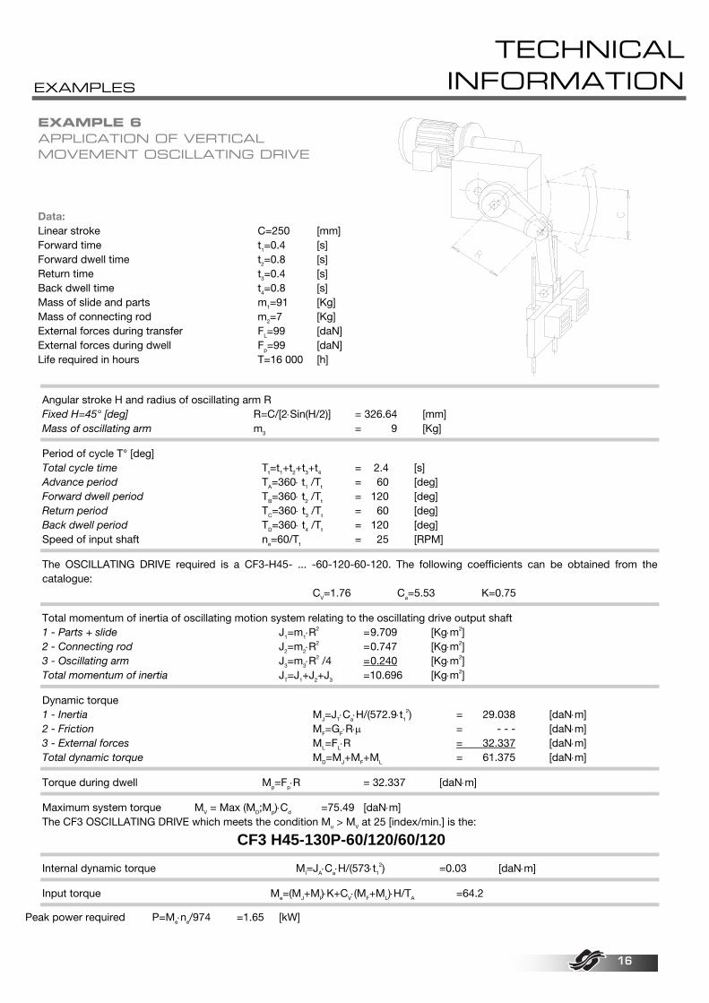
EXAMPLE 6 APPLICATION OF VERTICAL MOVEMENT OSCILLATING DRIVE Data: Linear stroke C=250 [mm] Forward time t1=0.4 [s] Forward dwell time t2=0.8 [s] Return time t3=0.4 [s] Back dwell time t4=0.8 [s] Mass of slide and parts m1=91 [Kg] Mass of connecting rod m2=7 [Kg] External forces during transfer FL=99 [daN] External forces during dwell Fp=99 [daN] Life required in hours T=16 000 [h]
Angular stroke H and radius of oscillating arm R Fixed H=45° [deg] R=C/[2⋅Sin(H/2)] = 326.64 [mm] Mass of oscillating arm m3 = 9 [Kg]
Period of cycle T° [deg] Total cycle time Tt=t1+t2+t3+t4 = 2.4 [s] Advance period TA=360⋅ t1 /Tt = 60 [deg] Forward dwell period TB=360⋅ t2 /Tt = 120 [deg] Return period TC=360⋅ t3 /Tt = 60 [deg] Back dwell period TD=360⋅ t4 /Tt = 120 [deg] Speed of input shaft ne=60/Tt = 25 [RPM]
The OSCILLATING DRIVE required is a CF3-H45- ... -60-120-60-120. The following coefficients can be obtained from the catalogue:
CV=1.76 Ca=5.53 K=0.75
Total momentum of inertia of oscillating motion system relating to the oscillating drive output shaft 1 - Parts + slide J1=m1⋅R
2 = 9.709 [Kg⋅m2] 2 - Connecting rod J2=m2⋅R
2 = 0.747 [Kg⋅m2] 3 - Oscillating arm J3=m3⋅R
2 /4 = 0.240 [Kg⋅m2] Total momentum of inertia JT=J1+J2+J3 =10.696 [Kg⋅m2]
Dynamic torque 1 - Inertia MJ=JT⋅Ca⋅H/(572.9⋅t1
2) = 29.038 [daN⋅m] 2 - Friction MF=GF⋅R⋅µ = - - - [daN⋅m] 3 - External forces ML=FL⋅R = 32.337 [daN⋅m] Total dynamic torque MD=MJ+MF+ML = 61.375 [daN⋅m]
Torque during dwell Mp=Fp⋅R = 32.337 [daN⋅m]
Maximum system torque MV = Max (MD;Mp)⋅Cd =75.49 [daN⋅m] The CF3 OSCILLATING DRIVE which meets the condition Mu > MV at 25 [index/min.] is the:
CF3 H45-130P-60/120/60/120
Internal dynamic torque MI=JA⋅Ca⋅H/(573⋅t1
2) =0.03 [daN⋅m]
Input torque Me=(MJ+MI)⋅K+CV⋅(MF+ML)⋅H/TA =64.2
Peak power required P=Me⋅ne/974 =1.65 [kW]