istanbul landfill gas-to-energy project k... · 2. the istanbul landfill gas-to-energy project...
TRANSCRIPT
ISTANBUL LANDFILL GAS-TO-ENERGY PROJECT
Yusuf K. Gülüt
Ortadogu Enerji A. S., Istanbul, Turkey and Akademi Teknik Musavirlik Co. Ltd., Istanbul, Turkey
e-mail: [email protected]
Abstract - Ortadogu Enerji AS of Istanbul, Turkey hasundertaken the Istanbul landfill gas-to-energy projectafter winning the tender held by the Istanbul Municipal-ity company ISTAC AS in March 2007. This projectincludes two major landfill sites, the Odayeri sitesituated near the Kemerburgaz and the Komurcuodasite near the Sile districts of Istanbul. Ortadogu EnerjiAS has made the investment for the design, constructionand operation of the two plants, and ISTAC AS receivesa portion of the income of the project. Electrical energyconversion has started in December 2008, currentlytotaling about 15 MW in both sites, expected to reach 25to 35 MW depending on the gas generation and collec-tion outcome of the sites. This report provides technicaldetails and salient features of the project. Lessonslearned during the execution of the project are alsopresented.
Keywords - renewable energy, landfill gas-to-energy,waste-to-energy, public-private partnership.
1. Introduction
Istanbul Municipality has started two major landfill sites in1995, one in the European and the other in the Asian part ofIstanbul. These accept municipal (domestic) waste and areplanned as sanitary landfills with the following features:• An impermeable bottom layer preventing the contamina-
tion of the ground water.• A system to drain and treat leachate water generated by
the waste and accumulated at the bottom.• Disposal of waste in planned deposit cells, compaction,
and covering by earth.• Collection and burning of the methane gas generated by
the waste.Odayeri landfill in the European side occupies about 0.5
million square meters of land and has accumulated about 32million tons of waste. Komurcuoda landfill in the Asian sideoccupies about 0.4 million square meters of land and hasabout 15 million tons of waste. Both landfills were closedin 2009 after reaching their maximum capacity. Figure 1placed at the end of the report shows their geographiclocation around the Bosphorus Strait.
The organic substances in any waste kept in a moist andoxygen free environment start to decompose and generatewhat is called “landfill gas”. Landfill gas contains methanegas CH4 at a concentration of 40-55%, the remainder beingcarbon dioxide and small amounts of other gases. The gasgeneration peaks within a year and then decays exponen-tially over tens of years, depending on the rain fall andaverage temperature in the region. In Istanbul, it is esti-mated that the above mentioned landfills shall have anaverage gas production of about 79% of the peak value overa 23 year period. It is not possible to stop the generation ofthe landfill gas in organic waste except by drying it highly.The generation of the landfill gas occurs as a result of thebiochemical decomposition action of the anaerobic bacteriawhich are always present and thrives in oxygen freeenvironments. When waste is left in contact with oxygen,aerobic bacteria prosper, and decompose the organicmaterial to generate only carbon dioxide and small amountsof other gases. Therefore, unless dried highly, organic wasteshould not be exposed to oxygen in order to preserve itsmethane potential.
During the decomposition process, water is formed inaddition to various gases. As a result, a dark colored liquidcalled leachate drains from the waste. Leachate is veryharmful if mixed with the ground water. Therefore, it mustbe carefully collected from the landfill, treated appropri-ately, and only then be discharged to the environment.
The methane gas has a global warming potential of 21times that of carbon dioxide. It is then better (actually lessworse) from an environmental point of view to release it tothe atmosphere after burning it appropriately. Therefore, aproperly constructed and maintained landfill should preventthe uncontrolled discharge of the methane gas by collectingand burning it under controlled conditions.
It is clear from the above discussion that constructingand operating a landfill is costly. Many municipalities in theworld either cannot perform all these processes properly, orstrain their budgets seriously.
On the other hand, since the landfill gas has about 50%methane, it can provide half the energy of natural gas.Therefore by burning the landfill gas in an engine coupledto an electrical generator, an otherwise wasted and harmfulsubstance could be both a source of renewable energy andan environmental gain. This is why a landfill gas-to-energysystem is a very meaningful concept and often quite aprofitable project.
International Renewable Energy Congress November 5-7, 2010 – Sousse, Tunisia
©IREC2010 1
2. The Istanbul Landfill Gas-to-Energy Project
Odayeri and Komurcuoda landfill sites are operated by themunicipality owned company ISTAC AS. In 2007, ISTACAS ran a tender for the design, construction, and operationof landfill gas-to-energy plants in these sites, and theprivate Ortadogu Group won the tender. This project is akind of public-private partnership (PPP). The municipalityassigns the energy generation rights to a private companyand the private company does the investment. The incomefrom the energy and carbon credit sales is shared by bothparties through an appropriate contract which lasts for 23years. Since Turkey has not yet joined the Kyoto Protocolin full, carbon credits generated in this project are traded inthe voluntary emission reductions (VER) market.
The Ortadogu Group of companies started business in1981. Today they have activities in land transportation,construction, renewable energy, and environmental technol-ogies. For the energy projects, a subsidiary company called“Ortadogu Energy AS” has been established. The group isactively pursuing to start projects in other modalities ofrenewable energy in addition to new landfill projects.
3. How a Landfill Gas-to-Energy System Works
A landfill gas-to-energy system essentially collects the gasgenerated in a landfill through a gentle suction, treats itbefore sending to gas engines which are coupled to electri-cal generators, and conditions the electrical energy gener-ated and conveys it to the national grid. These activitiescould be housed in steel transportation container typeenclosures in small capacity systems, or in plant buildingsfor larger capacities. In the Istanbul project, pre-fabricatedbuildings having 20 gen-set (motor-generator set) and 10gen-set capacity are employed for the Odayeri andKomurcuoda sites respectively.
Figure 2 presents a simplified schematic drawing of atypical landfill gas-to-energy plant.
A landfill gas-to-energy plant has the following maincomponents:A. Gas Collection
a. Gas collection well systemi. Well boreii. Perforated collection pipeiii. Settling resistant well structureiv. Well sealing
b. Leachate extraction systemi. Pneumatic pumpsii. Pressurized air supplyiii. Drain pipes
c. Gas transport systemi. Well to manifold pipingii. Header pipes with redundant ring connection
iii. By-pass valvesd. Condensate handling system
i. Monotonous slope for all pipesii. Siphon (U-tube) condensate trapsiii. Condensate tanks and pumping system
e. Manifold stationsi. Well pressure optimization systemii. Periodic gas analysis system
f. Compressed air systemB. Gas Conditioning
a. Blower system for suction and pressurizationb. Humidity removal systemc. Hydrogen Sulphide and Siloxane gas removal systemd. Flare system for burning the excess gase. Continuous gas analysis systemF. Gas collection SCADA System
C. Gas Storagea. Gas storage balloonsb. Gas storage SCADA systemc. Lightning protection system
Domestic Waste
Landfill
Gas Engines
Alternators Step-Down Transformer
Step-Up Transformers
Flare
Switch Gear
Energy Metering
National Electricity Grid
Gas Collection System
Gas Conditioning System
Leachate and Condensate
Management System
EnergyConsumingSystems
Landfill Gas (CH4 + CO2)
Landfill Gas Excess Landfill Gas
MechanicalPower
Electrical Power(Low Voltage)
Electrical Power(Medium Voltage)
CO2CO2
Figure 2. Simplified schematic drawing of a typical landfillgas-to-energy plant.
©IREC2010 2
D. Energy Conversiona. Gen-Set System
i. Gas Engineii. Electrical generator (Alternator)iii. Gen-set protection switchiv. Gen-set control systemv. Island mode gen-setsvi. Gen-sets SCADA system
b. Plant internal consumption systemi. Step-down transformer (34.5/0.4 kV)ii. Emergency stand-by diesel generator
E. Electrical Grid Connectiona. Step-up transformer (0.4/34.5 kV)b. Medium voltage switch gearc. Energy metering systemd. Grid coupling systeme. Underground cablef. Overhead transmission lineg. Coupling to the national grid (Feeder cell)h. Transmission line bird protection system
F. Plant Housinga. Container system for a small number of
gen-sets and building system for a larger number
b. Gen-set cooling air systemG. Support Systems
a. Gas field maintenance systemb. Gen-set maintenance systemc. Electrical switch-gear maintenance systemd. Transmission line maintenance systeme. Fire protection systemf. Personnel safety system
4. Salient features of the Istanbul LandfillGas-to-Energy Project
• The project management and system integration for thisproject has been realized by Ortadogu Enerji A S, andnot contracted out to an international company. In thisway, a significant accumulation of local expertise hasbeen realized.
• Imports of equipment from other countries have beenkept at the minimum and the resulting local contributionto the project has been realized at about 50%.
• Throughout the project design, high energy efficiencyand minimum total life cost have been the top priority,resulting in about 11.5 % more energy being deliveredto the national electric grid as compared to typicalproject implementations. (See Figure 3 at the end of thereport.)
• A contract management consultant has been employed,resulting in the signature of purchase and servicecontracts prepared by the buyer but not by the sellers.
• The following are some data about the project:• Conclusion of the tender and start of the project date:
March 2007.• Start of energy conversion: December 2008.• Public-Private Partnership project duration: 23 years.• Total power generated on both sites as of July 2010:
15 MW.• Total peak power estimated from both sites: Between
25 to 35 MW, depending on the gas generation andcollection outcome of the sites.
• Ratio of the 23 year average to the peak output:Estimated at about 79%.
• Total estimated carbon credits from both sites: Aboutone million ton/year CO2eq. for the first 7 years.
• Gas collection wells: Odayeri site 133, Komurcuoda111 wells, 80 cm dia., up to 43 m deep. New wellsof 60 meter deep are planned.
• Total length of gas, leachate and compressed airpipes: Odayeri site 50 km, Komurcuoda 38 km.
• Blower system capacities: Suction side -120 mbar,Pressure side +130 mbar, Odayeri site 17,500 Nm3/h,Komurcuoda 7,500 Nm3/h.
• Flare capacities: Odayeri site 5,000 Nm3/h, • Komurcuoda 2,500 Nm3/h.• Gen-Sets: Each with 1.4 MW power, a total of 18-25
units depending on the gas production and collectionoutcome of the landfill sites.
• Gas storage: Two balloons made of cloth-reinforcedplastic, each with 15,000 Nm3 capacity, utilized toaccumulate landfill gas during night hours of lowbuying tariff and consume during the day.
• Plant enclosure: Enclosed in pre-fabricated concretepower houses with 20 and 10 gen-set capacity,respectively for the Odayeri and Komurcuoda sites.
• Total investment cost: Approximately 35 millionEuros. (1.4 to 1.0 Million Euros per MW.)
• Pay-back period: Dependent upon the RenewableEnergy Purchase Price of the government, and thegas production/collection performance of the landfill.
• Figures 4 through 14 at the end of the report showvarious views from the plants.
5. Lessons Learned From This Project
• Problem encountered: During the project developmentphase, the landfill gas was analyzed for trace amounts ofgases which could be harmful for the engines, such ashydrogen sulphide (H2S) and siloxanes. Gas sampleswere collected by competent experts and analyses wereperformed in competent labs in Europe. The test resultswere considered satisfactory by engine manufacturers
©IREC2010 3

and a hydrogen sulphide or siloxane gas removal systemwas not indicated. However, after running only a fewthousand hours the engines developed excessive depos-its in their combustion chamber. Their manufacturerclaimed that the landfill gas contained excessive amountof siloxanes and this caused the deposits. They declaredmeasuring siloxanes by analyzing the gas samples asbeing unsatisfactory for evaluating the quality of alandfill gas, and stated that what counts is what happensin the engines, but not what the gas analyses say.Lesson learned: Evaluation of landfill gas for siloxanesis a very difficult task. Preferably install a siloxaneremoval system even if the engine manufacturer doesnot require. But, siloxane removal is a costly process.Better, choose an engine truly guaranteed by its manu-facturer to be tolerant to the siloxane levels existing inthe landfill gas. Also, keep in mind that landfill gas isnot a very stable product; the siloxane content maychange over years, even months. Carefully study thesiloxane problem in the literature before the plant designis finalized.
• Problem encountered: System integration performedlocally was not hundred percent successful, such as aninsufficient thermal insulation in a sub-system, whichneeded some re-work for correction. Design of theinsulation done by local experts was not satisfactory.Lesson learned: Make sure that the balance of the plantleft to the system integrator is specified in full detail,and that local expertise is available to design andmanufacture it satisfactorily. Balance of the plant is thatpart of a plant not provided by major suppliers such asgen-set manufacturers. Insist that all system suppliersprovide detailed production blue-prints for anythingthey do not supply but is needed for their system tooperate properly.
• Problem encountered: Landfill gas collection wellsproved to be not long-lasting. Some of them got cloggedby hard deposits inside the perforated pipe. Some wellsbecame deformed as a result of the settling and horizon-tal movements in the landfill. This resulted in reducedgas output and the need for opening and furnishing newwells.Lesson learned: Use multi segmented gas well pipingwith telescope-like joints. If required, use larger diame-ter gas well pipes. Set aside budget and be technicallyprepared to re-work on gas wells and open new wells.
• Problem encountered: Medium voltage overheadtransmission lines utilized to connect to the electric gridhad many short circuits due to storks and other big birdsperking on the towers located near the landfill.
Lesson learned: Active landfills attract birds in bigflocks. Take bird protection measures on the transmis-sion lines around the towers, such as extra insulationsleeves, bird repellants, etc.
• Problem encountered: A lot of unexpected manufac-turing defects in capital equipment, and dissatisfactionwith suppliers in correcting the problems were encoun-tered. This led to major disagreements over the contrac-tual obligations of the parties.Lesson learned: Luckily, comprehensive and prudentpurchase contracts was drafted and negotiated by acontract management consultant for this project, insteadof the buyer blindly signing the standard contract of thesuppliers. If it were not for this contract, the projectowner would have been totally helpless and unable toprotect its rights and countermove for the survival of theproject in a just way. Therefore, refrain from signing thestandard contracts of suppliers. Do not even try tomodify and improve on their contract drafts. Instead,write your own version of the contracts from scratch, byfollowing the steps below:• Study and analyze the processes, obligations of the
buyer and the seller, and risks involved in the busi-ness deal to be covered by the contract.
• Distribute the obligations and risks between thebuyer and seller in proportion to their ability toundertake and manage them.
• Specify the goods and services to be provided accu-rately, set measurable performance levels, and definepenalties when set performance levels are not met.This is known as the Service Level Agreement in theinformation technology field. This methodology isneeded in contracts in all fields.
• Study and clearly put in writing the obligations of thebuyer and supplier during commissioning, acceptanceand warranty periods.
• Include in the purchase contract, a legally bindingoffer from the supplier for an “After WarrantyMaintenance Contract” with reasonable terms.
• Include in the purchase contract, a legally bindingoffer from the supplier for the provision of durableand limited-life (consumable) maintenance supplies.Attach to the contract guaranteed price lists for allthese supplies, and clearly state the guaranteedservice life for the limited-life supplies.
©IREC2010 4

Figure 1. Geographic location of the landfill sites around the Bosphorus Strait.
(Figure 2 is embedded in the text)
Figure 3. In this project, 11.56 % more energy is being delivered to the national electric grid as compared totypical project implementations.
©IREC2010 5
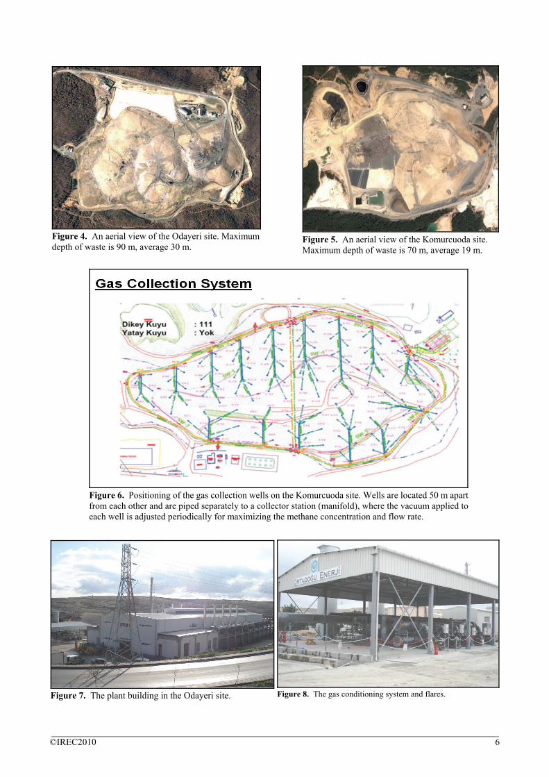
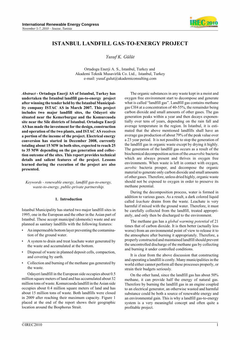
Figure 4. An aerial view of the Odayeri site. Maximumdepth of waste is 90 m, average 30 m.
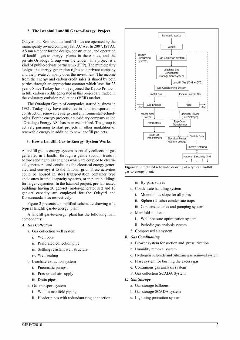
Figure 5. An aerial view of the Komurcuoda site.Maximum depth of waste is 70 m, average 19 m.
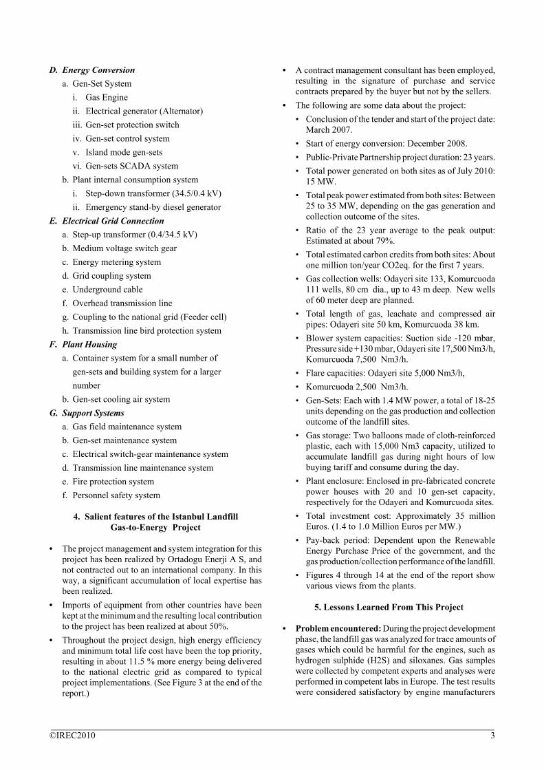
Figure 6. Positioning of the gas collection wells on the Komurcuoda site. Wells are located 50 m apartfrom each other and are piped separately to a collector station (manifold), where the vacuum applied toeach well is adjusted periodically for maximizing the methane concentration and flow rate.
Figure 8. The gas conditioning system and flares.Figure 7. The plant building in the Odayeri site.
©IREC2010 6
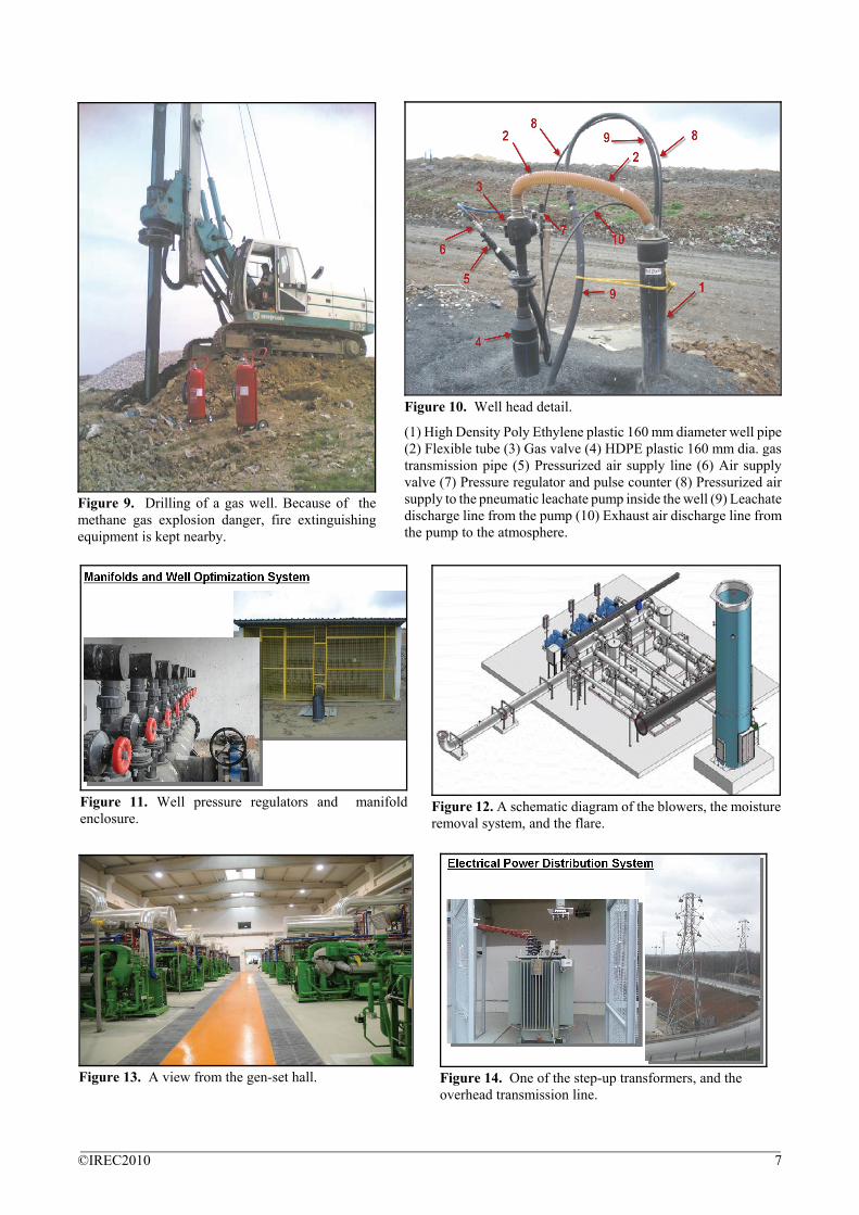
Figure 9. Drilling of a gas well. Because of themethane gas explosion danger, fire extinguishingequipment is kept nearby.
Figure 10. Well head detail.
(1) High Density Poly Ethylene plastic 160 mm diameter well pipe(2) Flexible tube (3) Gas valve (4) HDPE plastic 160 mm dia. gastransmission pipe (5) Pressurized air supply line (6) Air supplyvalve (7) Pressure regulator and pulse counter (8) Pressurized airsupply to the pneumatic leachate pump inside the well (9) Leachatedischarge line from the pump (10) Exhaust air discharge line fromthe pump to the atmosphere.
Figure 12. A schematic diagram of the blowers, the moistureremoval system, and the flare.
Figure 11. Well pressure regulators and manifoldenclosure.
Figure 13. A view from the gen-set hall. Figure 14. One of the step-up transformers, and theoverhead transmission line.
©IREC2010 7