issued for bid 72418 · 2018-07-25 · provide fire, extended coverage, vandalism, and malicious...
TRANSCRIPT
ISSUED FOR BID 72418

i
TABLE OF CONTENTS
PAGE NUMBERS
BIDDING REQUIREMENTS
Notice to Contractors and Advertisement for Bids 2 Pages Instructions and Information for Bidders 4 Pages Bid Proposal 7 Pages Non-Collusion Affidavit 1 Page CONTRACT FORMS Contract Form 3 Pages Bid Bond 2 Pages Payment Bond 3 Pages Performance Bond 3 Pages South Carolina Illegal Immigration Reform Act 1 Page SPECIFICATIONS
00700 General Conditions 65 Pages GENERAL REQUIREMENTS
01002 Supplementary Conditions 01002-1 thru 01002-14 01150 Measurement and Payment 01150-1 thru 01150-3
BJWSA TECHNICAL SPECIFICATIONS
CHAPTER 1 SAFETY DESIGN CONSIDERATIONS
1
CHAPTER 2 EARTHWORK2.1 SCOPE: 2
2.2 GENERAL: 2 2.3 CLEARING AND GRUBBING: 2 2.4 STRUCTURE EXCAVATION AND BACKFILL: 3 2.5 TRENCH EXCAVTION AND BACKFILL: 4 2.6 SITE GRADING: 6 CHAPTER 3 GRASSING AND SITE RESTORATION3.1 SCOPE: 8
3.2 GENERAL: 8 3.3 FERTILIZING AND GRASSING: 8 CHAPTER 4 ROADWAY REPAIR AND RESURFACING4.1 AGGREGATE SURFACING: 10
4.2 CUTTING AND REPLACING PAVEMENT: 10 4.3 RESURFACING OF EXISTING PAVEMENT: 11
ii
CHAPTER 5 BORING AND JACKING5.1 SCOPE: 13
5.2 GENERAL REQUIREMENTS: 13 5.3 MATERIALS: 13 5.4 INSTALLATION: 14
6.1 PIPE: 16 CHAPTER 6 PIPELINE MATERIALS, VALVES AND APPURTENANCES
6.2 VALVES: 21 6.3 FITTINGS, APPPURTENANCES AND SPECIALITIES: 24
7.1 SCOPE: 29 CHAPTER 7 WATER SYSTEM STANDARDS
7.2 WATER SYSTEM DESIGN GUIDELINES: 29 7.3 FIRE HYDRANTS AND POST TYPE FLUSHING HYDRANTS: 30 7.4 POTABLE WATER SERVICE CONNECTIONS: 31 7.5 WATER PIPELINE INSTALLATION: 33 7.6 PIPELINE TESTING AND DISINFECTION PROCEDURES: 36
8.1 SCOPE: 38 CHAPTER 8 WASTEWATER SYSTEM STANDARDS
8.2 INSTALLATION GUIDELINES: 38 8.3 PIPELINE TESTING PROCEDURES: 44
9.1 SCOPE: 46 CHAPTER 9 CONCRETE STRUCTURES, MANHOLES AND APPURTENANCES
9.2 MATERIALS: 46 9.3 TESTS OF STRUCTURES: 49
10.1 SCOPE: 50 CHAPTER 10 SEWER PUMP STATIONS AND APPURTENANCES
10.2 DESIGN CONSIDERATIONS: 50 10.3 PUMPS AND MOTORS: 54 10.4 TESTING AND STARTUP: 57 10.5 CLOSEOUT REQUIREMENTS: 58
11.1 GENERAL: 59 CHAPTER 11 ELECTRICAL
11.2 MAIN CONTROL PANEL: 60 11.3 SUBMERSIBLE PUMP STATIONS: 62 11.4 ABOVE GROUND SUCTION LIFT PUMP STATION: 63 11.5 QUALITY ASSURANCE: 63
iii
11.6 SUBMITTALS: 63 11.7 PRODUCTS/MATERIALS: 63 11.8 INSTALLATION: 64 11.9 ELECTRICAL SPARE PARTS: 64
12.1 SCADA DEFINITIONS: 65 CHAPTER 12 PUMP STATION SCADA SYSTEMS
12.2 SCADA I/O: 66
13.1 GENERAL: 68 CHAPTER 13 APPROVED MANUFACTURERS
13.2 PUMP STATIONS: 72 13.3 SEWER: 75 13.4 WATER: 80 HUSSEY GAY BELL TECHNICAL SPECIFICATIONS
03100 CONCRETE FORMWORK 03100-1 thru 03100-5 DIVISION 3 - CONCRETE
03200 CONCRETE REINFORCEMENT 03200-1 thru 03200-4 03250 CONCRETE JOINT ACCESSORIES 03250-1 thru 03250-2 03300 CAST-IN-PLACE CONCRETE 03300-1 thru 03300-10 03600 GROUT 03600-1 thru 03600-5
15065 FUSIBLE POLYVINYL CHLORIDE PIPE 15065-1 thru 15065-11 DIVISION 15 - MECHANICAL
16000 BASIC ELECTRICAL REQUIREMENTS 16000-1 thru 16000-7 DIVISION 16 - ELECTRICAL
16226 ELECTRIC MOTOR ACTUATOR FOR VALVES 16226-1 thru 16226-6 APPENDIX A GEOTECHNICAL ENGINEERING INVESTIGATION APPENDIX B MR SYSTEMS QUOTE - SCADA
NOTICE TO CONTRACTORS AND ADVERTISEMENT FOR BIDS
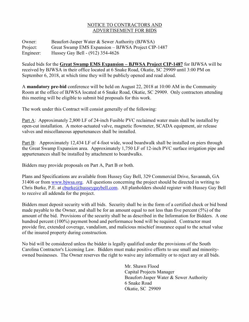
Owner: Beaufort-Jasper Water & Sewer Authority (BJWSA) Project: Great Swamp EMS Expansion – BJWSA Project CIP-1487 Engineer: Hussey Gay Bell - (912) 354-4626 Sealed bids for the Great Swamp EMS Expansion – BJWSA Project CIP-1487 for BJWSA will be received by BJWSA in their office located at 6 Snake Road, Okatie, SC 29909 until 3:00 PM on September 6, 2018, at which time they will be publicly opened and read aloud. A mandatory pre-bid conference will be held on August 22, 2018 at 10:00 AM in the Community Room at the office of BJWSA located at 6 Snake Road, Okatie, SC 29909. Only contractors attending this meeting will be eligible to submit bid proposals for this work. The work under this Contract will consist generally of the following: Part A: Approximately 2,800 LF of 24-inch Fusible PVC reclaimed water main shall be installed by open-cut installation. A motor-actuated valve, magnetic flowmeter, SCADA equipment, air release valves and miscellaneous appurtenances shall be installed. Part B: Approximately 12,434 LF of 4-foot wide, wood boardwalk shall be installed on piers through the Great Swamp Expansion area. Approximately 1,750 LF of 12-inch PVC surface irrigation pipe and appurtenances shall be installed by attachment to boardwalks. Bidders may provide proposals on Part A, Part B or both. Plans and Specifications are available from Hussey Gay Bell, 329 Commercial Drive, Savannah, GA 31406 or from www.bjwsa.org. All questions concerning the project should be directed in writing to Chris Burke, P.E. at [email protected]. All planholders should register with Hussey Gay Bell to receive all addenda for the project. Bidders must deposit security with all bids. Security shall be in the form of a certified check or bid bond made payable to the Owner, and shall be for an amount equal to not less than five percent (5%) of the amount of the bid. Provisions of the security shall be as described in the Information for Bidders. A one hundred percent (100%) payment bond and performance bond will be required. Contractor must provide fire, extended coverage, vandalism, and malicious mischief insurance equal to the actual value of the insured property during construction. No bid will be considered unless the bidder is legally qualified under the provisions of the South Carolina Contractor's Licensing Law. Bidders must make positive efforts to use small and minority-owned businesses. The Owner reserves the right to waive any informality or to reject any or all bids. Mr. Shawn Flood Capital Projects Manager Beaufort-Jasper Water & Sewer Authority 6 Snake Road Okatie, SC 29909
INSTRUCTION AND INFORMATION TO BIDDERS 1
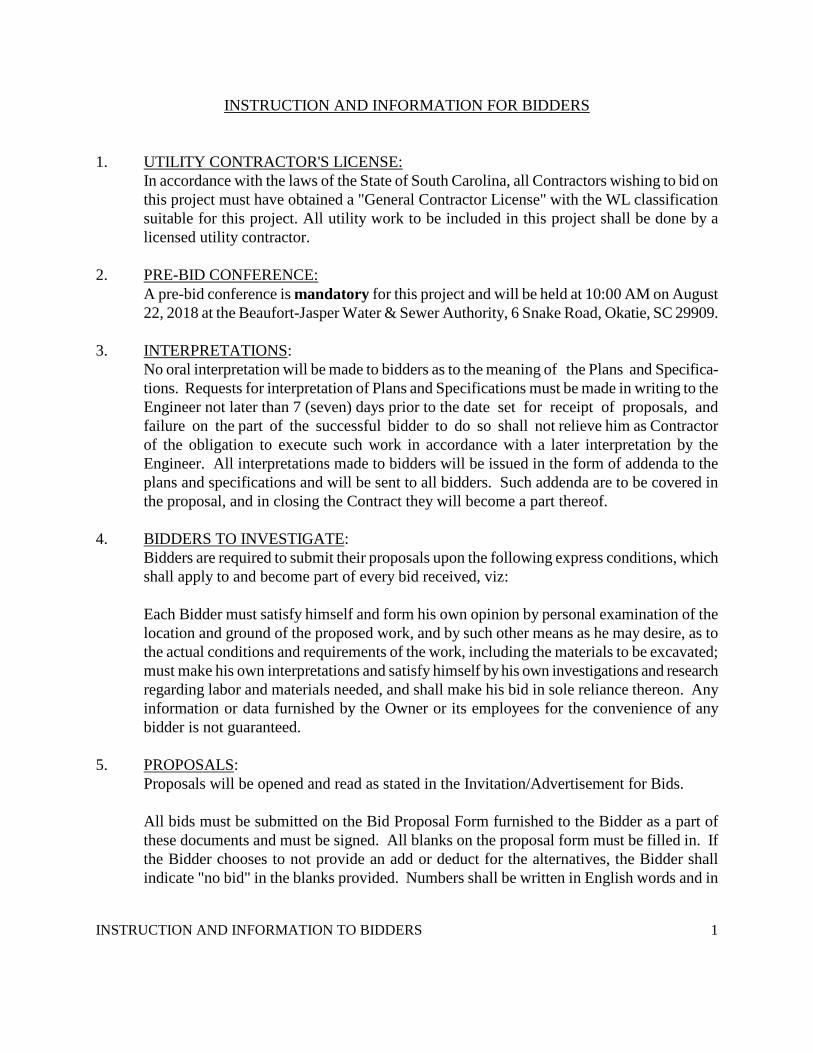
INSTRUCTION AND INFORMATION FOR BIDDERS
1.
In accordance with the laws of the State of South Carolina, all Contractors wishing to bid on this project must have obtained a "General Contractor License" with the WL classification suitable for this project. All utility work to be included in this project shall be done by a licensed utility contractor.
UTILITY CONTRACTOR'S LICENSE:
2.
A pre-bid conference is mandatory for this project and will be held at 10:00 AM on August 22, 2018 at the Beaufort-Jasper Water & Sewer Authority, 6 Snake Road, Okatie, SC 29909.
PRE-BID CONFERENCE:
3. INTERPRETATIONS
No oral interpretation will be made to bidders as to the meaning of the Plans and Specifica-tions. Requests for interpretation of Plans and Specifications must be made in writing to the Engineer not later than 7 (seven) days prior to the date set for receipt of proposals, and failure on the part of the successful bidder to do so shall not relieve him as Contractor of the obligation to execute such work in accordance with a later interpretation by the Engineer. All interpretations made to bidders will be issued in the form of addenda to the plans and specifications and will be sent to all bidders. Such addenda are to be covered in the proposal, and in closing the Contract they will become a part thereof.
:
4. BIDDERS TO INVESTIGATE
Bidders are required to submit their proposals upon the following express conditions, which shall apply to and become part of every bid received, viz:
:
Each Bidder must satisfy himself and form his own opinion by personal examination of the location and ground of the proposed work, and by such other means as he may desire, as to the actual conditions and requirements of the work, including the materials to be excavated; must make his own interpretations and satisfy himself by his own investigations and research regarding labor and materials needed, and shall make his bid in sole reliance thereon. Any information or data furnished by the Owner or its employees for the convenience of any bidder is not guaranteed.
5. PROPOSALS
Proposals will be opened and read as stated in the Invitation/Advertisement for Bids. :
All bids must be submitted on the Bid Proposal Form furnished to the Bidder as a part of these documents and must be signed. All blanks on the proposal form must be filled in. If the Bidder chooses to not provide an add or deduct for the alternatives, the Bidder shall indicate "no bid" in the blanks provided. Numbers shall be written in English words and in

INSTRUCTION AND INFORMATION TO BIDDERS 2
Arabic Numerals, and the completed form shall be without interlineation, alteration, or erasure. Failure to submit a proposal in the form requested or the inclusion of any condition, alternate, limitation or provision not called for will render the bid irregular and shall be considered sufficient cause for rejection of a bid. Failure to complete entries in all blanks in the proposal form shall be considered sufficient cause for rejection of a proposal.
All addenda issued shall be acknowledged in the place so designated.
Bid Security, made payable to the Owner, shall be in the amount of five percent (5%) of the Base Bid. Security shall be a Bid Bond issued by a surety licensed to conduct business in state where project is located, and shall have attached Power of Attorney certifying bond signee. A proposal cannot be withdrawn after it is filed, unless Bidder makes written request to the Owner prior to time set for opening of bids, or unless the Owner fails to accept bid within 60 days after date fixed for opening of bids. If any bidder refuses to enter into a contract, the Owner will retain his Bid Security as liquidated damages but not as a penalty. Submittal: The Proposal, in duplicate, and a single copy of the Bid Security together with the Power of Attorney shall be contained in a sealed envelope bearing the Bidder's name clearly addressed to the Owner as indicated on the Proposal Form. In addition, in large letters on both the front and back of the envelope, the following shall appear: "PROPOSAL FOR CONSTRUCTION. DO NOT OPEN UNTIL 3:00 PM SEPTEMBER 6, 2018 ". After that time, no proposals will be received or withdrawn.
6. AWARD
The Owner's intent is to make an award within funds available to the lowest responsible bidder furnishing satisfactory performance surety.
:
The Owner reserves the right to reject any or all bids and to waive technicalities and informalities.
If at the time this contract is to be awarded, the lowest bid (either base or owner-selected alternates) submitted by a responsible bidder does not exceed the amount of funds then estimated by the Owner as available to finance the contract, the contract will be awarded. The Owner reserves the right to select the alternates to be used in determining the lowest bid. If such bid exceeds such amount, the Owner may reject all bids. The Owner will decide which bidder is the lowest qualified bidder, and in determining such bidder, the following elements will be considered for each bidder:
a. Maintains a permanent place of business.
b. Has adequate plant equipment and personnel to perform the work properly

INSTRUCTION AND INFORMATION TO BIDDERS 3
and expeditiously. c. Has suitable financial status to meet obligations incident to the work. d. Has appropriate technical experience.
7. CONTRACTOR TO BE SATISFACTORY TO OWNER
The Contract will not be awarded to any bidder or bidders who have failed in any contractual obligations to the Owner, or who has on any previous contract performed in a manner unsatisfactory to the Owner, either as to the character of the work, the fulfillment of guarantees or the time consumed in its completion.
:
Bidders shall, upon written request and prior to the letting of a contract, furnish the Owner with the following information relative to his own business and that of each of the subcontractors named in his Bid Proposal. The Owner reserves the right to evaluate and disqualify bids from bidders whose information is deemed unsatisfactory, in the opinion of the Owner, for the scope of this project.
(a) A statement of his experience with projects of similar scope, including a list of
projects for which he or his firm was a responsible contractor or subcontractor; such lists shall indicate the name or identification and location of each project, the year it was completed, a brief description and the approximate dollar value of the work for which he was responsible.
(b) A statement of experience of each subcontractor in his Bid Proposal; each statement
shall include a list of projects for which the named subcontractor was a responsible contractor or subcontractor; such lists shall include the name or identification and location of each project, the year is was completed, a brief description and the approximate dollar value of the work for which the named subcontractor was responsible.
(c) The amount of capital and equipment the Bidder has available for the work of the
project.
(d) The amount of capital and equipment each of the named subcontractors has available for the work of the project.
(e) A statement showing the financial assets and liabilities of the Bidder, certified by a Certified Public Accountant.
(f) A statement from each of the named subcontractors showing his assets and liabilities,
certified by a Certified Public Accountant. 8. LIQUIDATED DAMAGES:
INSTRUCTION AND INFORMATION TO BIDDERS 4
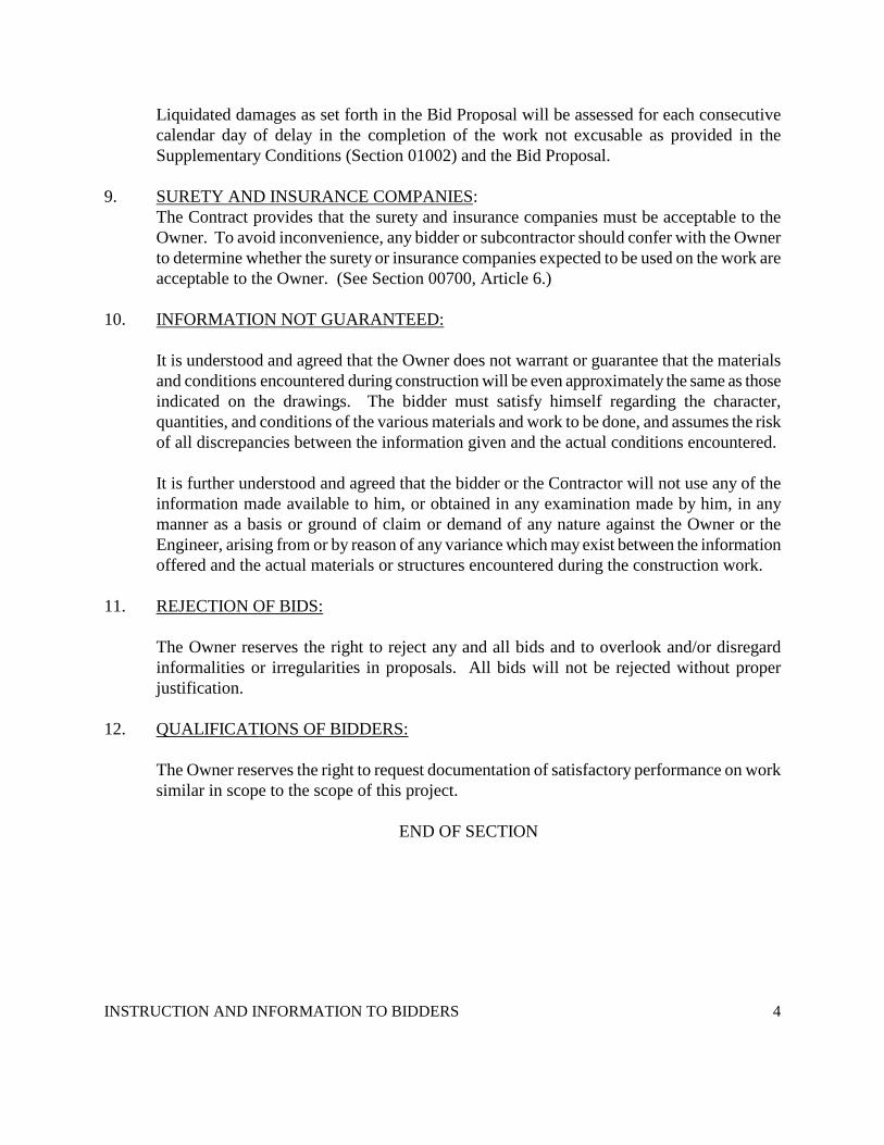
Liquidated damages as set forth in the Bid Proposal will be assessed for each consecutive calendar day of delay in the completion of the work not excusable as provided in the Supplementary Conditions (Section 01002) and the Bid Proposal.
9. SURETY AND INSURANCE COMPANIES
The Contract provides that the surety and insurance companies must be acceptable to the Owner. To avoid inconvenience, any bidder or subcontractor should confer with the Owner to determine whether the surety or insurance companies expected to be used on the work are acceptable to the Owner. (See Section 00700, Article 6.)
:
10. INFORMATION NOT GUARANTEED:
It is understood and agreed that the Owner does not warrant or guarantee that the materials and conditions encountered during construction will be even approximately the same as those indicated on the drawings. The bidder must satisfy himself regarding the character, quantities, and conditions of the various materials and work to be done, and assumes the risk of all discrepancies between the information given and the actual conditions encountered. It is further understood and agreed that the bidder or the Contractor will not use any of the information made available to him, or obtained in any examination made by him, in any manner as a basis or ground of claim or demand of any nature against the Owner or the Engineer, arising from or by reason of any variance which may exist between the information offered and the actual materials or structures encountered during the construction work.
11.
REJECTION OF BIDS:
The Owner reserves the right to reject any and all bids and to overlook and/or disregard informalities or irregularities in proposals. All bids will not be rejected without proper justification.
12.
QUALIFICATIONS OF BIDDERS:
The Owner reserves the right to request documentation of satisfactory performance on work similar in scope to the scope of this project.
END OF SECTION

1
BID PROPOSAL
Mr. Shawn Flood Capital Projects Manager Beaufort-Jasper Water & Sewer Authority 6 Snake Road Okatie, SC 29909 PROJECT TITLE: GREAT SWAMP EMS EXPANSION – BJWSA PROJECT CIP-1487 SUBMITTED BY: ____________________________________________________________ DATE SUBMITTED: __________________________________________________________ Gentlemen: Having carefully examined the Plans, Specifications, and other Contract Documents relating to the BJWSA’s Great Swamp EMS Expansion, dated June 2018, and Addendum No.(s), and also having carefully inspected the premises and the conditions affecting the work, the undersigned hereby proposes and agrees to furnish all materials, labor, skill, equipment, tools, and other items of every kind and description specified, needed or used for the complete execution of all work covered by and in conformity with the aforesaid Plans, Specifications, and other Contract Documents prepared by Hussey Gay Bell, (hereinafter called the “Engineer”) and all Amendments and Addenda thereto, for the sums hereinafter stated.
FIRST. In submitting this Bid proposal, the undersigned bidder understands and agrees to the Instructions and Information to Bidders. The Bidder acknowledges that he has received and examined the Plans and Specifications, and has informed himself of all Addenda thereto, and of the form of the Contract to be furnished in the event he is the successful bidder and is awarded the Contract. SECOND. The Undersigned Bidder agrees, if the successful bidder, to execute the contract in form as set forth in the Specifications and to furnish a Performance Bond in an amount of 100 percent of the Contract amount as security for the faithful performance of the Contract and a Payment Bond in an amount of 100 percent of the Contract amount for the payment of all persons performing labor and/or furnishing materials in connection with the Contract and the fulfillment of such guarantees as are hereinafter specified, and insurance as set forth in the Specifications, all within 10 days of receiving notice of award of contract by the Owner. THIRD. The Undersigned Bidder further agrees to begin the work on receipt of the executed contract and Notice to Proceed and to prosecute said work so as to complete work except as otherwise specified under this Contract within the time as specified in the Special Conditions.
2
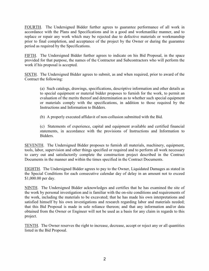
FOURTH. The Undersigned Bidder further agrees to guarantee performance of all work in accordance with the Plans and Specifications and in a good and workmanlike manner, and to replace or repair any work which may be rejected due to defective materials or workmanship prior to final completion, and acceptance of the project by the Owner or during the guarantee period as required by the Specifications. FIFTH. The Undersigned Bidder further agrees to indicate on his Bid Proposal, in the space provided for that purpose, the names of the Contractor and Subcontractors who will perform the work if his proposal is accepted. SIXTH. The Undersigned Bidder agrees to submit, as and when required, prior to award of the Contract the following:
(a) Such catalogs, drawings, specifications, descriptive information and other details as to special equipment or material bidder proposes to furnish for the work, to permit an evaluation of the merits thereof and determination as to whether such special equipment or materials comply with the specifications, in addition to those required by the Instructions and Information to Bidders. (b) A properly executed affidavit of non-collusion submitted with the Bid. (c) Statements of experience, capital and equipment available and certified financial statements, in accordance with the provisions of Instructions and Information to Bidders.
SEVENTH. The Undersigned Bidder proposes to furnish all materials, machinery, equipment, tools, labor, supervision and other things specified or required and to perform all work necessary to carry out and satisfactorily complete the construction project described in the Contract Documents in the manner and within the times specified in the Contract Documents. EIGHTH. The Undersigned Bidder agrees to pay to the Owner, Liquidated Damages as stated in the Special Conditions for each consecutive calendar day of delay in an amount not to exceed $1,000.00 per day. NINTH. The Undersigned Bidder acknowledges and certifies that he has examined the site of the work by personal investigation and is familiar with the on-site conditions and requirements of the work, including the materials to be excavated; that he has made his own interpretations and satisfied himself by his own investigations and research regarding labor and materials needed; that this Bid Proposal is made in sole reliance thereon; and that any information and/or data obtained from the Owner or Engineer will not be used as a basis for any claim in regards to this project. TENTH. The Owner reserves the right to increase, decrease, accept or reject any or all quantities listed in the Bid Proposal.
3
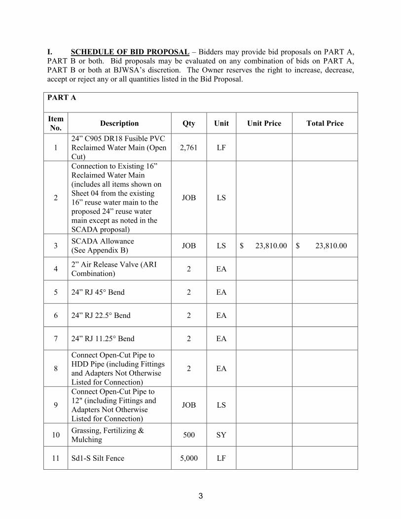
I. SCHEDULE OF BID PROPOSAL – Bidders may provide bid proposals on PART A, PART B or both. Bid proposals may be evaluated on any combination of bids on PART A, PART B or both at BJWSA’s discretion. The Owner reserves the right to increase, decrease, accept or reject any or all quantities listed in the Bid Proposal. PART A
Item No. Description Qty Unit Unit Price Total Price
1 24” C905 DR18 Fusible PVC Reclaimed Water Main (Open Cut)
2,761 LF
2
Connection to Existing 16” Reclaimed Water Main (includes all items shown on Sheet 04 from the existing 16” reuse water main to the proposed 24” reuse water main except as noted in the SCADA proposal)
JOB LS
3 SCADA Allowance (See Appendix B) JOB LS $ 23,810.00 $ 23,810.00
4 2” Air Release Valve (ARI Combination) 2 EA
5 24” RJ 45° Bend 2 EA
6 24” RJ 22.5° Bend 2 EA
7 24” RJ 11.25° Bend 2 EA
8
Connect Open-Cut Pipe to HDD Pipe (including Fittings and Adapters Not Otherwise Listed for Connection)
2 EA
9
Connect Open-Cut Pipe to 12" (including Fittings and Adapters Not Otherwise Listed for Connection)
JOB LS
10 Grassing, Fertilizing & Mulching 500 SY
11 Sd1-S Silt Fence 5,000 LF
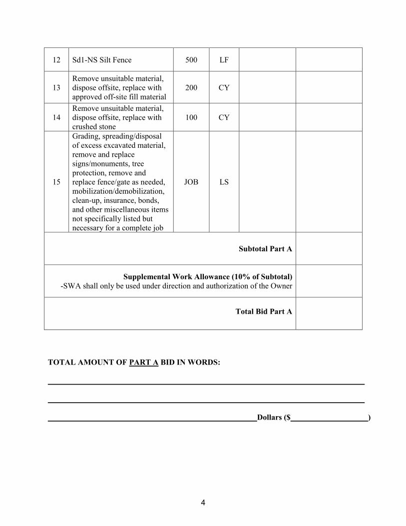
4
12 Sd1-NS Silt Fence 500 LF
13 Remove unsuitable material, dispose offsite, replace with approved off-site fill material
200 CY
14 Remove unsuitable material, dispose offsite, replace with crushed stone
100 CY
15
Grading, spreading/disposal of excess excavated material, remove and replace signs/monuments, tree protection, remove and replace fence/gate as needed, mobilization/demobilization, clean-up, insurance, bonds, and other miscellaneous items not specifically listed but necessary for a complete job
JOB LS
Subtotal Part A
Supplemental Work Allowance (10% of Subtotal) -SWA shall only be used under direction and authorization of the Owner
Total Bid Part A
TOTAL AMOUNT OF PART A BID IN WORDS: Dollars ($ )

5
PART B
Item No.
Description Qty Unit Unit Price Total Price
1 12” Kroy QS2P PVC Surface (Distribution) Pipe attached to Boardwalk
1,748 LF
2 4’ Distribution Boardwalk 1,748 LF
3 4’ Monitoring Boardwalk 10,684 LF
4 Boardwalk Intersections, Transitions, Stairs and Specialties
JOB LS
5
Mobilization/demobilization, clean-up, insurance, bonds, and other miscellaneous items not specifically listed but necessary for a complete job
JOB LS
Subtotal Part B
Supplemental Work Allowance (10% of Subtotal) -SWA shall only be used under direction and authorization of the Owner
Total Bid Part B
TOTAL AMOUNT OF PART B BID IN WORDS: Dollars ($ )

6
Undersigned agrees that this proposal may not be revoked or withdrawn after the time set for the opening of bids except as provided by South Carolina laws. Bids shall remain open for acceptance for a period of sixty (60) days following bid opening. In case he be notified in writing by mail, telegraph, or delivery of the acceptance of the Proposal within ninety days after the time set for the opening of bids, the Undersigned agrees to execute within ten days a Contract (Form of Agreement between Contractor and Owner) for the work for the above stated compensation and at the same time to furnish and deliver to the Owner a Performance Bond and Payment Bond in accordance with the instructions bound in the specifications, both in an amount equal to 100 percent of the contract sum. The Undersigned agrees to commence actual physical work on the site with an adequate force and equipment within ten days of a date to be specified in a written order from the Owner and to complete fully all work within 180 consecutive calendar days for Part A and 270 consecutive calendar days for Part B. The Undersigned Bidder agrees to pay to the Owner, Liquidated Damages as stated in the Special Conditions for each consecutive calendar day of delay in an amount not to exceed $1,000.00 per day. II. CERTIFICATION AND EXECUTION We hereby attest that we have ( ) have not ( ) [check appropriate space] previously performed work subject to President's Executive Order No. 11246 and 11375, as amended, pertaining to employment practices and obligating us to non-discrimination against any employee or applicants for employment because of race, color, creed, sex or national origin. Enclosed herein is Proposal Guarantee in the form of Bid Bond in the amount of ________________________________________________________($______________) payable to the Beaufort-Jasper Water & Sewer Authority. The amount of the Proposal Guarantee is at least five (5) percent of the amount of the Total Bid as required by the Advertisement for Bids and by the Instructions and Information to Bidders. The Bid Bond must be submitted on a form acceptable to the Owner. The Undersigned agrees that the above stated amount is the proper measure of liquidated damages which the Owner will sustain by the failure of the Undersigned to execute the Contract and to furnish the performance Bond and Payment Bond in case this proposal is accepted and further agrees to the following: If this Proposal is accepted within 60 days after the date set for the opening of bids and the Undersigned fails to execute the Contract within 10 days after written notice of such acceptance or if he fails to furnish both a Performance Bond and Payment Bond, the obligation of the Bid Bond will remain in full force and effect and the money payable thereon shall be paid into the funds of the Owner as Liquidated Damages for such failure; otherwise the obligation of the Bid Bond will be null and void.

7
Receipt is acknowledged of the following addenda: Addenda _____, _____, _____, _____ WITNESS our hands and seal this __________ day of _________, 2018. INDIVIDUAL OR PARTNER- SHIP EXECUTION Co-partners doing business under name and style of CORPORATE EXECUTION A Corporation of the State of (Corporate Seal) By: TITLE By: TITLE MAILING ADDRESS PHONE NUMBER STREET ADDRESS

NONCOLLUSION AFFIDAVIT
(THIS AFFIDAVIT IS TO ACCOMPANY THE BID)
STATE OF SOUTH CAROLINA COUNTY OF _____________________ _______________________________, of lawful age, being first duly sworn, on oath says that (s)he is the agent authorized by the bidder to submit the attached bid. Affiant further states that the bidder has not been a party to any collusion among bidders in restraint of freedom of competition by agreement to bid at a fixed price or to refrain from bidding; or with any state official or employee as to the quantity, quality, or price in the prospective contract, or any other terms of said prospective contract; or in any discussions between bidders and any state official concerning exchange of money or other thing of value for special consideration in the letting of a contract. Company ______________________________ Signature _____________________________ Title _________________________________ Subscribed and sworn to before me this ____ day of ________, 20___.
Notary Public __________________________ My Commission Expires: ____________________
Contract Form 1
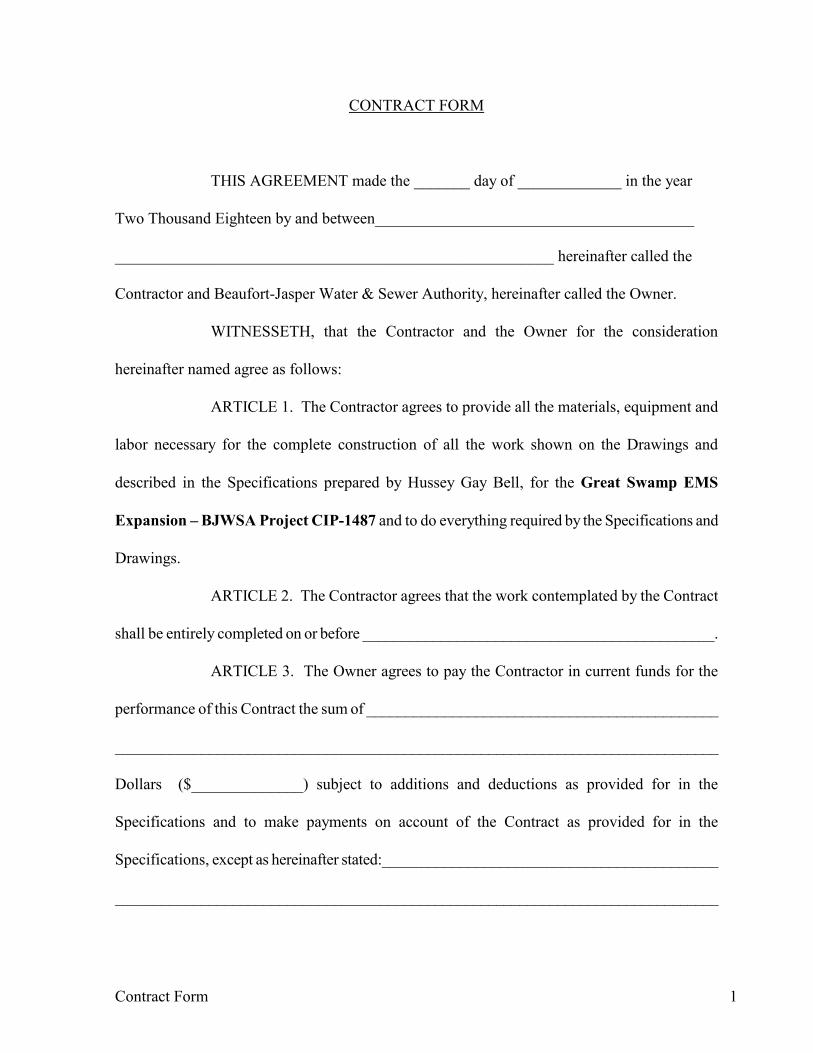
CONTRACT FORM
THIS AGREEMENT made the _______ day of _____________ in the year
Two Thousand Eighteen by and between________________________________________
_______________________________________________________ hereinafter called the
Contractor and Beaufort-Jasper Water & Sewer Authority, hereinafter called the Owner.
WITNESSETH, that the Contractor and the Owner for the consideration
hereinafter named agree as follows:
ARTICLE 1. The Contractor agrees to provide all the materials, equipment and
labor necessary for the complete construction of all the work shown on the Drawings and
described in the Specifications prepared by Hussey Gay Bell, for the Great Swamp EMS
Expansion – BJWSA Project CIP-1487 and to do everything required by the Specifications and
Drawings.
ARTICLE 2. The Contractor agrees that the work contemplated by the Contract
shall be entirely completed on or before _____________________________________________.
ARTICLE 3. The Owner agrees to pay the Contractor in current funds for the
performance of this Contract the sum of _____________________________________________
______________________________________________________________________________
Dollars ($______________) subject to additions and deductions as provided for in the
Specifications and to make payments on account of the Contract as provided for in the
Specifications, except as hereinafter stated:___________________________________________
______________________________________________________________________________
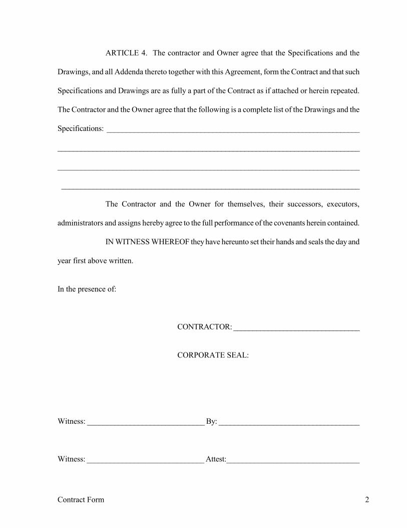
Contract Form 2
ARTICLE 4. The contractor and Owner agree that the Specifications and the
Drawings, and all Addenda thereto together with this Agreement, form the Contract and that such
Specifications and Drawings are as fully a part of the Contract as if attached or herein repeated.
The Contractor and the Owner agree that the following is a complete list of the Drawings and the
Specifications: _________________________________________________________________
______________________________________________________________________________
______________________________________________________________________________
_____________________________________________________________________________
The Contractor and the Owner for themselves, their successors, executors,
administrators and assigns hereby agree to the full performance of the covenants herein contained.
IN WITNESS WHEREOF they have hereunto set their hands and seals the day and
year first above written.
In the presence of: CONTRACTOR: _________________________________
CORPORATE SEAL: Witness: ______________________________ By: ____________________________________ Witness: ______________________________ Attest:__________________________________

Contract Form 3
OWNER: _______________________________________
SEAL: Witness:_______________________________ By: ____________________________________ Witness: ______________________________ Attest: __________________________________

PENAL SUM FORM
EJCDC C-430 Bid Bond (Penal Sum Form) Prepared by the Engineers Joint Contract Documents Committee.
Page 1 of 2
BID BOND
Any singular reference to Bidder, Surety, Owner or other party shall be considered plural where applicable.
BIDDER (Name and Address): SURETY (Name and Address of Principal Place of Business): OWNER (Name and Address): BID Bid Due Date: Description (Project Name and Include Location): BOND Bond Number: Date (Not earlier than Bid due date): Penal sum $ (Words) (Figures) Surety and Bidder, intending to be legally bound hereby, subject to the terms set forth below, do each cause this Bid Bond to be duly executed by an authorized officer, agent, or representative. BIDDER SURETY (Seal) (Seal) Bidder’s Name and Corporate Seal Surety’s Name and Corporate Seal By: By: Signature Signature (Attach Power of Attorney) Print Name Print Name Title Title Attest: Attest: Signature Signature Title Title Note: Above addresses are to be used for giving any required notice. Provide execution by any additional parties, such as joint venturers, if necessary.
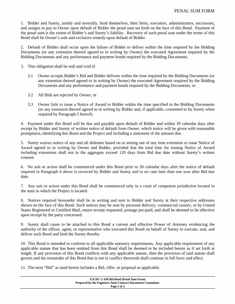
PENAL SUM FORM
EJCDC C-430 Bid Bond (Penal Sum Form) Prepared by the Engineers Joint Contract Documents Committee.
Page 2 of 2
1. Bidder and Surety, jointly and severally, bind themselves, their heirs, executors, administrators, successors, and assigns to pay to Owner upon default of Bidder the penal sum set forth on the face of this Bond. Payment of the penal sum is the extent of Bidder’s and Surety’s liability. Recovery of such penal sum under the terms of this Bond shall be Owner’s sole and exclusive remedy upon default of Bidder.
2. Default of Bidder shall occur upon the failure of Bidder to deliver within the time required by the Bidding Documents (or any extension thereof agreed to in writing by Owner) the executed Agreement required by the Bidding Documents and any performance and payment bonds required by the Bidding Documents.
3. This obligation shall be null and void if:
3.1 Owner accepts Bidder’s Bid and Bidder delivers within the time required by the Bidding Documents (or any extension thereof agreed to in writing by Owner) the executed Agreement required by the Bidding Documents and any performance and payment bonds required by the Bidding Documents, or
3.2 All Bids are rejected by Owner, or
3.3 Owner fails to issue a Notice of Award to Bidder within the time specified in the Bidding Documents (or any extension thereof agreed to in writing by Bidder and, if applicable, consented to by Surety when required by Paragraph 5 hereof).
4. Payment under this Bond will be due and payable upon default of Bidder and within 30 calendar days after receipt by Bidder and Surety of written notice of default from Owner, which notice will be given with reasonable promptness, identifying this Bond and the Project and including a statement of the amount due.
5. Surety waives notice of any and all defenses based on or arising out of any time extension to issue Notice of Award agreed to in writing by Owner and Bidder, provided that the total time for issuing Notice of Award including extensions shall not in the aggregate exceed 120 days from Bid due date without Surety’s written consent.
6. No suit or action shall be commenced under this Bond prior to 30 calendar days after the notice of default required in Paragraph 4 above is received by Bidder and Surety and in no case later than one year after Bid due date.
7. Any suit or action under this Bond shall be commenced only in a court of competent jurisdiction located in the state in which the Project is located.
8. Notices required hereunder shall be in writing and sent to Bidder and Surety at their respective addresses shown on the face of this Bond. Such notices may be sent by personal delivery, commercial courier, or by United States Registered or Certified Mail, return receipt requested, postage pre-paid, and shall be deemed to be effective upon receipt by the party concerned.
9. Surety shall cause to be attached to this Bond a current and effective Power of Attorney evidencing the authority of the officer, agent, or representative who executed this Bond on behalf of Surety to execute, seal, and deliver such Bond and bind the Surety thereby.
10. This Bond is intended to conform to all applicable statutory requirements. Any applicable requirement of any applicable statute that has been omitted from this Bond shall be deemed to be included herein as if set forth at length. If any provision of this Bond conflicts with any applicable statute, then the provision of said statute shall govern and the remainder of this Bond that is not in conflict therewith shall continue in full force and effect.
11. The term “Bid” as used herein includes a Bid, offer, or proposal as applicable.

{MW001504;1} EJCDC C-615(A) Payment Bond March 2008 Prepared by the Engineers Joint Contract Documents Committee.
Page 1 of 3
PAYMENT BOND
Any singular reference to Contractor, Surety, Owner, or other party shall be considered plural where applicable.
CONTRACTOR (Name and Address): SURETY (Name, and Address of Principal Place of Business):
OWNER (Name and Address): CONTRACT Effective Date of Agreement: Amount: Description (Name and Location): BOND Bond Number:
Date (Not earlier than Effective Date of Agreement):
Amount: Modifications to this Bond Form: Surety and Contractor, intending to be legally bound hereby, subject to the terms set forth below, do each cause this Payment Bond to be duly executed by an authorized officer, agent, or representative. CONTRACTOR AS PRINCIPAL SURETY (Seal) (Seal) Contractor's Name and Corporate Seal Surety’s Name and Corporate Seal By: By: Signature Signature (Attach Power of Attorney) Print Name Print Name Title Title Attest: Attest: Signature Signature Title Title Note: Provide execution by additional parties, such as joint venturers, if necessary.

{MW001504;1} EJCDC C-615(A) Payment Bond March 2008 Prepared by the Engineers Joint Contract Documents Committee.
Page 2 of 3
1. Contractor and Surety, jointly and severally, bind themselves, their heirs, executors, administrators, successors, and assigns to Owner to pay for labor, materials, and equipment furnished by Claimants for use in the performance of the Contract, which is incorporated herein by reference.
2. With respect to Owner, this obligation shall be null and void if Contractor:
2.1 Promptly makes payment, directly or indirectly, for all sums due Claimants, and
2.2 Defends, indemnifies, and holds harmless Owner from all claims, demands, liens, or suits alleging non-payment by Contractor by any person or entity who furnished labor, materials, or equipment for use in the performance of the Contract, provided Owner has promptly notified Contractor and Surety (at the addresses described in Paragraph 12) of any claims, demands, liens, or suits and tendered defense of such claims, demands, liens, or suits to Contractor and Surety, and provided there is no Owner Default.
3. With respect to Claimants, this obligation shall be null and void if Contractor promptly makes payment, directly or indirectly, for all sums due.
4. Surety shall have no obligation to Claimants under this Bond until:
4.1 Claimants who are employed by or have a direct contract with Contractor have given notice to Surety (at the address described in Paragraph 12) and sent a copy, or notice thereof, to Owner, stating that a claim is being made under this Bond and, with substantial accuracy, the amount of the claim.
4.2 Claimants who do not have a direct contract with Contractor:
1. Have furnished written notice to Contractor and sent a copy, or notice thereof, to Owner, within 90 days after having last performed labor or last furnished materials or equipment included in the claim stating, with substantial accuracy, the amount of the claim and the name of the party to whom the materials or equipment were furnished or supplied, or for whom the labor was done or performed; and
2. Have either received a rejection in whole or in part from Contractor, or not received within 30 days of furnishing the above notice any communication from Contractor by which Contractor had indicated the claim will be paid directly or indirectly; and
3. Not having been paid within the above 30 days, have sent a written notice to Surety (at the address described in Paragraph 12) and sent a copy, or notice thereof, to Owner, stating that a claim is being made under this Bond and enclosing a copy of the previous written notice furnished to Contractor.
5. If a notice by a Claimant required by Paragraph 4 is provided by Owner to Contractor or to Surety, that is sufficient compliance.
6. Reserved.
7. Surety’s total obligation shall not exceed the amount of this Bond, and the amount of this Bond shall be credited for any payments made in good faith by Surety.
8. Amounts owed by Owner to Contractor under the Contract shall be used for the performance of the Contract and to satisfy claims, if any, under any performance bond. By Contractor furnishing and Owner accepting this Bond, they agree that all funds earned by Contractor in the performance of the Contract are dedicated to satisfy obligations of Contractor and Surety under this Bond, subject to Owner’s priority to use the funds for the completion of the Work.
9. Surety shall not be liable to Owner, Claimants, or others for obligations of Contractor that are unrelated to the Contract. Owner shall not be liable for payment of any costs or expenses of any Claimant under this Bond, and shall have under this Bond no obligations to make payments to, give notices on behalf of, or otherwise have obligations to Claimants under this Bond.
{MW001504;1} EJCDC C-615(A) Payment Bond March 2008 Prepared by the Engineers Joint Contract Documents Committee.
Page 3 of 3
10. Surety hereby waives notice of any change, including changes of time, to the Contract or to related subcontracts, purchase orders, and other obligations.
11. No suit or action shall be commenced by a Claimant under this Bond other than in a court of competent jurisdiction in the location in which the Work or part of the Work is located or after the expiration of one year from the date (1) on which the Claimant gave the notice required by Paragraph 4.1 or Paragraph 4.2.3, or (2) on which the last labor or service was performed by anyone or the last materials or equipment were furnished by anyone under the Contract, whichever of (1) or (2) first occurs. If the provisions of this paragraph are void or prohibited by law, the minimum period of limitation available to sureties as a defense in the jurisdiction of the suit shall be applicable.
12. Notice to Surety, Owner, or Contractor shall be mailed or delivered to the addresses shown on the signature page. Actual receipt of notice by Surety, Owner, or Contractor, however accomplished, shall be sufficient compliance as of the date received at the address shown on the signature page.
13. When this Bond has been furnished to comply with a statutory requirement in the location where the Contract was to be performed, any provision in this Bond conflicting with said statutory requirement shall be deemed deleted herefrom and provisions conforming to such statutory requirement shall be deemed incorporated herein. The intent is that this Bond shall be construed as a statutory Bond and not as a common law bond.
14. Upon request of any person or entity appearing to be a potential beneficiary of this Bond, Contractor shall promptly furnish a copy of this Bond or shall permit a copy to be made.
15. Definitions
15.1 Claimant: An individual or entity having a direct contract with Contractor, or with a first-tier subcontractor of Contractor, to furnish labor, materials, or equipment for use in the performance of the Contract. The intent of this Bond shall be to include without limitation in the terms “labor, materials or equipment” that part of water, gas, power, light, heat, oil, gasoline, telephone service, or rental equipment used in the Contract, architectural and engineering services required for performance of the Work of Contractor and Contractor’s subcontractors, and all other items for which a mechanic’s lien may be asserted in the jurisdiction where the labor, materials, or equipment were furnished.
15.2 Contract: The agreement between Owner and Contractor identified on the signature page, including all Contract Documents and changes thereto.
15.3 Owner Default: Failure of Owner, which has neither been remedied nor waived, to pay Contractor as required by the Contract, or to perform and complete or otherwise comply with the other terms thereof.
FOR INFORMATION ONLY – (Name, Address, and Telephone) Surety Agency or Broker: Owner’s Representative (Engineer or other):
EJCDC C-610 Performance Bond Prepared by the Engineers Joint Contract Documents Committee.
Page 1 of 3
PERFORMANCE BOND
Any singular reference to Contractor, Surety, Owner, or other party shall be considered plural where applicable.
CONTRACTOR (Name and Address): SURETY (Name, and Address of Principal Place of Business): OWNER (Name and Address): CONTRACT Effective Date of Agreement: Amount: Description (Name and Location): BOND Bond Number:
Date (Not earlier than Effective Date of Agreement):
Amount: Modifications to this Bond Form: Surety and Contractor, intending to be legally bound hereby, subject to the terms set forth below, do each cause this Performance Bond to be duly executed by an authorized officer, agent, or representative. CONTRACTOR AS PRINCIPAL SURETY (Seal) (Seal) Contractor's Name and Corporate Seal Surety’s Name and Corporate Seal By: By: Signature Signature (Attach Power of Attorney) Print Name Print Name Title Title Attest: Attest: Signature Signature Title Title Note: Provide execution by additional parties, such as joint venturers, if necessary.
EJCDC C-610 Performance Bond Prepared by the Engineers Joint Contract Documents Committee.
Page 2 of 3
Contractor and Surety, jointly and severally, bind themselves, their heirs, executors, administrators, successors, and assigns to Owner for the performance of the Contract, which is incorporated herein by reference. 1. If Contractor performs the Contract, Surety and Contractor have no obligation under this Bond, except to participate in conferences as provided in Paragraph 2.1. 2. If there is no Owner Default, Surety’s obligation under this Bond shall arise after:
2.1 Owner has notified Contractor and Surety, at the addresses described in Paragraph 9 below, that Owner is considering declaring a Contractor Default and has requested and attempted to arrange a conference with Contractor and Surety to be held not later than 15 days after receipt of such notice to discuss methods of performing the Contract. If Owner, Contractor, and Surety agree, Contractor shall be allowed a reasonable time to perform the Contract, but such an agreement shall not waive Owner’s right, if any, subsequently to declare a Contractor Default; and
2.2 Owner has declared a Contractor Default and formally terminated Contractor’s right to complete the Contract. Such Contractor Default shall not be declared earlier than 20 days after Contractor and Surety have received notice as provided in Paragraph 2.1; and
2.3 Owner has agreed to pay the Balance of the Contract Price to: 1. Surety in accordance with the terms of the Contract; or 2. Another contractor selected pursuant to Paragraph 3.3 to perform the Contract.
3. When Owner has satisfied the conditions of Paragraph 2, Surety shall promptly, and at Surety’s expense, take one of the following actions:
3.1 Arrange for Contractor, with consent of Owner, to perform and complete the Contract; or 3.2 Undertake to perform and complete the Contract itself, through its agents or through independent
contractors; or 3.3 Obtain bids or negotiated proposals from qualified contractors acceptable to Owner for a contract
for performance and completion of the Contract, arrange for a contract to be prepared for execution by Owner and contractor selected with Owner’s concurrence, to be secured with performance and payment bonds executed by a qualified surety equivalent to the bonds issued on the Contract, and pay to Owner the amount of damages as described in Paragraph 5 in excess of the Balance of the Contract Price incurred by Owner resulting from Contractor Default; or
3.4 Waive its right to perform and complete, arrange for completion, or obtain a new contractor, and with reasonable promptness under the circumstances:
1. After investigation, determine the amount for which it may be liable to Owner and, as soon as practicable after the amount is determined, tender payment therefor to Owner; or
2. Deny liability in whole or in part and notify Owner citing reasons therefor.
4. If Surety does not proceed as provided in Paragraph 3 with reasonable promptness, Surety shall be deemed to be in default on this Bond 15 days after receipt of an additional written notice from Owner to Surety demanding that Surety perform its obligations under this Bond, and Owner shall be entitled to enforce any remedy available to Owner. If Surety proceeds as provided in Paragraph 3.4, and Owner refuses the payment tendered or Surety has denied liability, in whole or in part, without further notice Owner shall be entitled to enforce any remedy available to Owner. 5. After Owner has terminated Contractor’s right to complete the Contract, and if Surety elects to act under Paragraph 3.1, 3.2, or 3.3 above, then the responsibilities of Surety to Owner shall not be greater than those of Contractor under the Contract, and the responsibilities of Owner to Surety shall not be greater than those of Owner under the Contract. To the limit of the amount of this Bond, but subject to commitment by Owner of the Balance of the Contract Price to mitigation of costs and damages on the Contract, Surety is obligated without duplication for:

EJCDC C-610 Performance Bond Prepared by the Engineers Joint Contract Documents Committee.
Page 3 of 3
5.1 The responsibilities of Contractor for correction of defective Work and completion of the Contract; 5.2 Additional legal, design professional, and delay costs resulting from Contractor’s Default, and
resulting from the actions of or failure to act of Surety under Paragraph 3; and 5.3 Liquidated damages, or if no liquidated damages are specified in the Contract, actual damages
caused by delayed performance or non-performance of Contractor.
6. Surety shall not be liable to Owner or others for obligations of Contractor that are unrelated to the Contract, and the Balance of the Contract Price shall not be reduced or set off on account of any such unrelated obligations. No right of action shall accrue on this Bond to any person or entity other than Owner or its heirs, executors, administrators, or successors. 7. Surety hereby waives notice of any change, including changes of time, to Contract or to related subcontracts, purchase orders, and other obligations. 8. Any proceeding, legal or equitable, under this Bond may be instituted in any court of competent jurisdiction in the location in which the Work or part of the Work is located, and shall be instituted within two years after Contractor Default or within two years after Contractor ceased working or within two years after Surety refuses or fails to perform its obligations under this Bond, whichever occurs first. If the provisions of this paragraph are void or prohibited by law, the minimum period of limitation available to sureties as a defense in the jurisdiction of the suit shall be applicable. 9. Notice to Surety, Owner, or Contractor shall be mailed or delivered to the address shown on the signature page. 10. When this Bond has been furnished to comply with a statutory requirement in the location where the Contract was to be performed, any provision in this Bond conflicting with said statutory requirement shall be deemed deleted herefrom and provisions conforming to such statutory requirement shall be deemed incorporated herein. The intent is that this Bond shall be construed as a statutory bond and not as a common law bond. 11. Definitions.
11.1 Balance of the Contract Price: The total amount payable by Owner to Contractor under the Contract after all proper adjustments have been made, including allowance to Contractor of any amounts received or to be received by Owner in settlement of insurance or other Claims for damages to which Contractor is entitled, reduced by all valid and proper payments made to or on behalf of Contractor under the Contract.
11.2 Contract: The agreement between Owner and Contractor identified on the signature page, including all Contract Documents and changes thereto.
11.3 Contractor Default: Failure of Contractor, which has neither been remedied nor waived, to perform or otherwise to comply with the terms of the Contract.
11.4 Owner Default: Failure of Owner, which has neither been remedied nor waived, to pay Contractor as required by the Contract or to perform and complete or otherwise comply with the other terms thereof.
FOR INFORMATION ONLY – (Name, Address and Telephone) Surety Agency or Broker: Owner’s Representative (Engineer or other party):

03/2009
1
SOUTH CAROLINA ILLEGAL IMMIGRATION REFORM ACT
CONTRACTOR CERTIFICATION
In accordance with the requirements of the South Carolina Illegal Immigration Reform Act, ______________________ (“Contractor”) hereby certifies that it is currently in compliance with the requirements of Title 8, Chapter 14 of the S.C. Code Annotated and will remain in compliance with such requirements throughout the term of its contract with Beaufort-Jasper Water & Sewer Authority
Contractor hereby acknowledges that in order to comply with requirements of S.C. Code Annotated Section 8-14-20(B), it will:
(“Owner”).
1. Register and participate in the federal work authorization program (E-Verify) to verify the employment authorization of all new employees; and require agreement from its subcontractors, and through the subcontractors, the sub-subcontractors, to register and participate in the federal verification the employment authorization of all new employees.
OR
2. Employ only workers who:
a. Possess a valid South Carolina driver’s license or identification card issued by the South Carolina Department of Motor Vehicles; or
b. are eligible to obtain a South Carolina driver’s license or identification card in that they meet the requirements set forth in S.C. Code Annotated Sections 56-1-40 through 56-1-90; or
c. possess a valid driver’s license or identification card from another state where the license requirements are at least as strict as those in South Carolina, as determined by the South Carolina Department of Motor Vehicles
Contractor agrees to provide to Owner any documentation required to establish the applicability of the South Carolina Illegal Immigration Reform Act to the Contractor, subcontractor, or sub-subcontractor. Contractor further agrees that it will provide Owner with any documentation required to establish that the Contractor and any subcontractors or sub-subcontractors are in compliance with the requirements of Title 8, Chapter 14 of the S.C. Code Annotated.
Date:________________________ By:________________________________________
Title:_______________________________________

EJCDC® C‐700, Standard General Conditions of the Construction Contract. Copyright © 2013 National Society of Professional Engineers, American Council of Engineering Companies,
and American Society of Civil Engineers. All rights reserved.
This document has important legal consequences; consultation with an attorney is encouraged with respect to its use or modification. This document should be adapted to the particular circumstances of the contemplated Project and the controlling Laws and Regulations.
STANDARD GENERAL CONDITIONS OF THE CONSTRUCTION CONTRACT
EJCDC® C‐700, Standard General Conditions of the Construction Contract. Copyright © 2013 National Society of Professional Engineers, American Council of Engineering Companies,
and American Society of Civil Engineers. All rights reserved.
These General Conditions have been prepared for use with the Agreement Between Owner and Contractor for Construction Contract (EJCDC® C‐520, Stipulated Sum, or C‐525, Cost‐Plus, 2013 Editions). Their provisions are interrelated and a change in one may necessitate a change in the other.
To prepare supplementary conditions that are coordinated with the General Conditions, use EJCDC’s Guide to the Preparation of Supplementary Conditions (EJCDC® C‐800, 2013 Edition). The full EJCDC Construction series of documents is discussed in the Commentary on the 2013 EJCDC Construction Documents (EJCDC® C‐001, 2013 Edition).
Copyright © 2013:
National Society of Professional Engineers
1420 King Street, Alexandria, VA 22314‐2794
(703) 684‐2882
www.nspe.org
American Council of Engineering Companies
1015 15th Street N.W., Washington, DC 20005
(202) 347‐7474
www.acec.org
American Society of Civil Engineers
1801 Alexander Bell Drive, Reston, VA 20191‐4400
(800) 548‐2723
www.asce.org
The copyright for this document is owned jointly by the three sponsoring organizations listed above. The National Society of Professional Engineers is the Copyright Administrator for the EJCDC documents; please direct all inquiries regarding EJCDC copyrights to NSPE.
NOTE: EJCDC publications may be purchased at www.ejcdc.org, or from any of the sponsoring organizations above.

EJCDC® C‐700, Standard General Conditions of the Construction Contract. Copyright © 2013 National Society of Professional Engineers, American Council of Engineering Companies,
and American Society of Civil Engineers. All rights reserved. Page i
STANDARD GENERAL CONDITIONS OF THE CONSTRUCTION CONTRACT
TABLE OF CONTENTS
Page Article 1 – Definitions and Terminology ......................................................................................... 1
1.01 Defined Terms ........................................................................................................................ 1
1.02 Terminology ........................................................................................................................... 5
Article 2 – Preliminary Matters ....................................................................................................... 6
2.01 Delivery of Bonds and Evidence of Insurance ........................................................................ 6
2.02 Copies of Documents ............................................................................................................. 6
2.03 Before Starting Construction ................................................................................................. 6
2.04 Preconstruction Conference; Designation of Authorized Representatives ........................... 7
2.05 Initial Acceptance of Schedules ............................................................................................. 7
2.06 Electronic Transmittals ........................................................................................................... 7
Article 3 – Documents: Intent, Requirements, Reuse .................................................................... 8
3.01 Intent ...................................................................................................................................... 8
3.02 Reference Standards .............................................................................................................. 8
3.03 Reporting and Resolving Discrepancies ................................................................................. 8
3.04 Requirements of the Contract Documents ............................................................................ 9
3.05 Reuse of Documents ............................................................................................................ 10
Article 4 – Commencement and Progress of the Work ................................................................ 10
4.01 Commencement of Contract Times; Notice to Proceed ...................................................... 10
4.02 Starting the Work ................................................................................................................. 10
4.03 Reference Points .................................................................................................................. 10
4.04 Progress Schedule ................................................................................................................ 10
4.05 Delays in Contractor’s Progress ........................................................................................... 11
Article 5 – Availability of Lands; Subsurface and Physical Conditions; Hazardous Environmental Conditions ..................................................................................................................................... 12
5.01 Availability of Lands ............................................................................................................. 12
5.02 Use of Site and Other Areas ................................................................................................. 12
5.03 Subsurface and Physical Conditions ..................................................................................... 13
5.04 Differing Subsurface or Physical Conditions ........................................................................ 14
5.05 Underground Facilities ......................................................................................................... 15

EJCDC® C‐700, Standard General Conditions of the Construction Contract. Copyright © 2013 National Society of Professional Engineers, American Council of Engineering Companies,
and American Society of Civil Engineers. All rights reserved. Page ii
5.06 Hazardous Environmental Conditions at Site....................................................................... 17
Article 6 – Bonds and Insurance ................................................................................................... 19
6.01 Performance, Payment, and Other Bonds ........................................................................... 19
6.02 Insurance—General Provisions ............................................................................................ 19
6.03 Contractor’s Insurance ......................................................................................................... 20
6.04 Owner’s Liability Insurance .................................................................................................. 23
6.05 Property Insurance ............................................................................................................... 23
6.06 Waiver of Rights ................................................................................................................... 25
6.07 Receipt and Application of Property Insurance Proceeds ................................................... 25
Article 7 – Contractor’s Responsibilities ....................................................................................... 26
7.01 Supervision and Superintendence ....................................................................................... 26
7.02 Labor; Working Hours .......................................................................................................... 26
7.03 Services, Materials, and Equipment ..................................................................................... 26
7.04 “Or Equals” ........................................................................................................................... 27
7.05 Substitutes ........................................................................................................................... 28
7.06 Concerning Subcontractors, Suppliers, and Others ............................................................. 29
7.07 Patent Fees and Royalties .................................................................................................... 31
7.08 Permits ................................................................................................................................. 31
7.09 Taxes .................................................................................................................................... 32
7.10 Laws and Regulations ........................................................................................................... 32
7.11 Record Documents ............................................................................................................... 32
7.12 Safety and Protection ........................................................................................................... 32
7.13 Safety Representative .......................................................................................................... 33
7.14 Hazard Communication Programs ....................................................................................... 33
7.15 Emergencies ......................................................................................................................... 34
7.16 Shop Drawings, Samples, and Other Submittals .................................................................. 34
7.17 Contractor’s General Warranty and Guarantee................................................................... 36
7.18 Indemnification .................................................................................................................... 37
7.19 Delegation of Professional Design Services ......................................................................... 37
Article 8 – Other Work at the Site ................................................................................................ 38
8.01 Other Work .......................................................................................................................... 38
8.02 Coordination ........................................................................................................................ 39
8.03 Legal Relationships ............................................................................................................... 39

EJCDC® C‐700, Standard General Conditions of the Construction Contract. Copyright © 2013 National Society of Professional Engineers, American Council of Engineering Companies,
and American Society of Civil Engineers. All rights reserved. Page iii
Article 9 – Owner’s Responsibilities .............................................................................................. 40
9.01 Communications to Contractor ............................................................................................ 40
9.02 Replacement of Engineer ..................................................................................................... 40
9.03 Furnish Data ......................................................................................................................... 40
9.04 Pay When Due ...................................................................................................................... 40
9.05 Lands and Easements; Reports, Tests, and Drawings .......................................................... 40
9.06 Insurance .............................................................................................................................. 40
9.07 Change Orders ...................................................................................................................... 40
9.08 Inspections, Tests, and Approvals ........................................................................................ 41
9.09 Limitations on Owner’s Responsibilities .............................................................................. 41
9.10 Undisclosed Hazardous Environmental Condition ............................................................... 41
9.11 Evidence of Financial Arrangements .................................................................................... 41
9.12 Safety Programs ................................................................................................................... 41
Article 10 – Engineer’s Status During Construction ...................................................................... 41
10.01 Owner’s Representative ....................................................................................................... 41
10.02 Visits to Site .......................................................................................................................... 41
10.03 Project Representative ......................................................................................................... 42
10.04 Rejecting Defective Work ..................................................................................................... 42
10.05 Shop Drawings, Change Orders and Payments .................................................................... 42
10.06 Determinations for Unit Price Work .................................................................................... 42
10.07 Decisions on Requirements of Contract Documents and Acceptability of Work ................ 42
10.08 Limitations on Engineer’s Authority and Responsibilities .................................................... 42
10.09 Compliance with Safety Program ......................................................................................... 43
Article 11 – Amending the Contract Documents; Changes in the Work ...................................... 43
11.01 Amending and Supplementing Contract Documents .......................................................... 43
11.02 Owner‐Authorized Changes in the Work ............................................................................. 44
11.03 Unauthorized Changes in the Work ..................................................................................... 44
11.04 Change of Contract Price ..................................................................................................... 44
11.05 Change of Contract Times .................................................................................................... 45
11.06 Change Proposals ................................................................................................................. 45
11.07 Execution of Change Orders ................................................................................................. 46
11.08 Notification to Surety ........................................................................................................... 47
Article 12 – Claims ......................................................................................................................... 47
EJCDC® C‐700, Standard General Conditions of the Construction Contract. Copyright © 2013 National Society of Professional Engineers, American Council of Engineering Companies,
and American Society of Civil Engineers. All rights reserved. Page iv
12.01 Claims ................................................................................................................................... 47
Article 13 – Cost of the Work; Allowances; Unit Price Work ........................................................ 48
13.01 Cost of the Work .................................................................................................................. 48
13.02 Allowances ........................................................................................................................... 50
13.03 Unit Price Work .................................................................................................................... 51
Article 14 – Tests and Inspections; Correction, Removal or Acceptance of Defective Work ....... 52
14.01 Access to Work ..................................................................................................................... 52
14.02 Tests, Inspections, and Approvals ........................................................................................ 52
14.03 Defective Work..................................................................................................................... 53
14.04 Acceptance of Defective Work ............................................................................................. 53
14.05 Uncovering Work ................................................................................................................. 53
14.06 Owner May Stop the Work .................................................................................................. 54
14.07 Owner May Correct Defective Work .................................................................................... 54
Article 15 – Payments to Contractor; Set‐Offs; Completion; Correction Period .......................... 55
15.01 Progress Payments ............................................................................................................... 55
15.02 Contractor’s Warranty of Title ............................................................................................. 58
15.03 Substantial Completion ........................................................................................................ 58
15.04 Partial Use or Occupancy ..................................................................................................... 59
15.05 Final Inspection .................................................................................................................... 59
15.06 Final Payment ....................................................................................................................... 59
15.07 Waiver of Claims .................................................................................................................. 61
15.08 Correction Period ................................................................................................................. 61
Article 16 – Suspension of Work and Termination ....................................................................... 62
16.01 Owner May Suspend Work .................................................................................................. 62
16.02 Owner May Terminate for Cause ......................................................................................... 62
16.03 Owner May Terminate For Convenience ............................................................................. 63
16.04 Contractor May Stop Work or Terminate ............................................................................ 63
Article 17 – Final Resolution of Disputes ...................................................................................... 64
17.01 Methods and Procedures ..................................................................................................... 64
Article 18 – Miscellaneous ............................................................................................................ 64
18.01 Giving Notice ........................................................................................................................ 64
18.02 Computation of Times .......................................................................................................... 64
18.03 Cumulative Remedies .......................................................................................................... 64
EJCDC® C‐700, Standard General Conditions of the Construction Contract. Copyright © 2013 National Society of Professional Engineers, American Council of Engineering Companies,
and American Society of Civil Engineers. All rights reserved. Page v
18.04 Limitation of Damages ......................................................................................................... 65
18.05 No Waiver ............................................................................................................................ 65
18.06 Survival of Obligations ......................................................................................................... 65
18.07 Controlling Law .................................................................................................................... 65
18.08 Headings ............................................................................................................................... 65
EJCDC® C‐700, Standard General Conditions of the Construction Contract. Copyright © 2013 National Society of Professional Engineers, American Council of Engineering Companies,
and American Society of Civil Engineers. All rights reserved. Page 1 of 65
ARTICLE 1 – DEFINITIONS AND TERMINOLOGY
1.01 Defined Terms
A. Wherever used in the Bidding Requirements or Contract Documents, a term printed with initial capital letters, including the term’s singular and plural forms, will have the meaning indicated in the definitions below. In addition to terms specifically defined, terms with initial capital letters in the Contract Documents include references to identified articles and paragraphs, and the titles of other documents or forms.
1. Addenda—Written or graphic instruments issued prior to the opening of Bids which clarify, correct, or change the Bidding Requirements or the proposed Contract Documents.
2. Agreement—The written instrument, executed by Owner and Contractor, that sets forth the Contract Price and Contract Times, identifies the parties and the Engineer, and designates the specific items that are Contract Documents.
3. Application for Payment—The form acceptable to Engineer which is to be used by Contractor during the course of the Work in requesting progress or final payments and which is to be accompanied by such supporting documentation as is required by the Contract Documents.
4. Bid—The offer of a Bidder submitted on the prescribed form setting forth the prices for the Work to be performed.
5. Bidder—An individual or entity that submits a Bid to Owner.
6. Bidding Documents—The Bidding Requirements, the proposed Contract Documents, and all Addenda.
7. Bidding Requirements—The advertisement or invitation to bid, Instructions to Bidders, Bid Bond or other Bid security, if any, the Bid Form, and the Bid with any attachments.
8. Change Order—A document which is signed by Contractor and Owner and authorizes an addition, deletion, or revision in the Work or an adjustment in the Contract Price or the Contract Times, or other revision to the Contract, issued on or after the Effective Date of the Contract.
9. Change Proposal—A written request by Contractor, duly submitted in compliance with the procedural requirements set forth herein, seeking an adjustment in Contract Price or Contract Times, or both; contesting an initial decision by Engineer concerning the requirements of the Contract Documents or the acceptability of Work under the Contract Documents; challenging a set‐off against payments due; or seeking other relief with respect to the terms of the Contract.
10. Claim—(a) A demand or assertion by Owner directly to Contractor, duly submitted in compliance with the procedural requirements set forth herein: seeking an adjustment of Contract Price or Contract Times, or both; contesting an initial decision by Engineer concerning the requirements of the Contract Documents or the acceptability of Work under the Contract Documents; contesting Engineer’s decision regarding a Change Proposal; seeking resolution of a contractual issue that Engineer has declined to address; or seeking other relief with respect to the terms of the Contract; or (b) a demand or assertion by Contractor directly to Owner, duly submitted in compliance with the procedural requirements set forth herein, contesting Engineer’s decision regarding a Change Proposal; or seeking resolution of a contractual issue that Engineer
EJCDC® C‐700, Standard General Conditions of the Construction Contract. Copyright © 2013 National Society of Professional Engineers, American Council of Engineering Companies,
and American Society of Civil Engineers. All rights reserved. Page 2 of 65
has declined to address. A demand for money or services by a third party is not a Claim.
11. Constituent of Concern—Asbestos, petroleum, radioactive materials, polychlorinated biphenyls (PCBs), hazardous waste, and any substance, product, waste, or other material of any nature whatsoever that is or becomes listed, regulated, or addressed pursuant to (a) the Comprehensive Environmental Response, Compensation and Liability Act, 42 U.S.C. §§9601 et seq. (“CERCLA”); (b) the Hazardous Materials Transportation Act, 49 U.S.C. §§5501 et seq.; (c) the Resource Conservation and Recovery Act, 42 U.S.C. §§6901 et seq. (“RCRA”); (d) the Toxic Substances Control Act, 15 U.S.C. §§2601 et seq.; (e) the Clean Water Act, 33 U.S.C. §§1251 et seq.; (f) the Clean Air Act, 42 U.S.C. §§7401 et seq.; or (g) any other federal, state, or local statute, law, rule, regulation, ordinance, resolution, code, order, or decree regulating, relating to, or imposing liability or standards of conduct concerning, any hazardous, toxic, or dangerous waste, substance, or material.
12. Contract—The entire and integrated written contract between the Owner and Contractor concerning the Work.
13. Contract Documents—Those items so designated in the Agreement, and which together comprise the Contract.
14. Contract Price—The money that Owner has agreed to pay Contractor for completion of the Work in accordance with the Contract Documents. .
15. Contract Times—The number of days or the dates by which Contractor shall: (a) achieve Milestones, if any; (b) achieve Substantial Completion; and (c) complete the Work.
16. Contractor—The individual or entity with which Owner has contracted for performance of the Work.
17. Cost of the Work—See Paragraph 13.01 for definition.
18. Drawings—The part of the Contract that graphically shows the scope, extent, and character of the Work to be performed by Contractor.
19. Effective Date of the Contract—The date, indicated in the Agreement, on which the Contract becomes effective.
20. Engineer—The individual or entity named as such in the Agreement.
21. Field Order—A written order issued by Engineer which requires minor changes in the Work but does not change the Contract Price or the Contract Times.
22. Hazardous Environmental Condition—The presence at the Site of Constituents of Concern in such quantities or circumstances that may present a danger to persons or property exposed thereto. The presence at the Site of materials that are necessary for the execution of the Work, or that are to be incorporated in the Work, and that are controlled and contained pursuant to industry practices, Laws and Regulations, and the requirements of the Contract, does not establish a Hazardous Environmental Condition.
23. Laws and Regulations; Laws or Regulations—Any and all applicable laws, statutes, rules, regulations, ordinances, codes, and orders of any and all governmental bodies, agencies, authorities, and courts having jurisdiction.

EJCDC® C‐700, Standard General Conditions of the Construction Contract. Copyright © 2013 National Society of Professional Engineers, American Council of Engineering Companies,
and American Society of Civil Engineers. All rights reserved. Page 3 of 65
24. Liens—Charges, security interests, or encumbrances upon Contract‐related funds, real property, or personal property.
25. Milestone—A principal event in the performance of the Work that the Contract requires Contractor to achieve by an intermediate completion date or by a time prior to Substantial Completion of all the Work.
26. Notice of Award—The written notice by Owner to a Bidder of Owner’s acceptance of the Bid.
27. Notice to Proceed—A written notice by Owner to Contractor fixing the date on which the Contract Times will commence to run and on which Contractor shall start to perform the Work.
28. Owner—The individual or entity with which Contractor has contracted regarding the Work, and which has agreed to pay Contractor for the performance of the Work, pursuant to the terms of the Contract.
29. Progress Schedule—A schedule, prepared and maintained by Contractor, describing the sequence and duration of the activities comprising the Contractor’s plan to accomplish the Work within the Contract Times.
30. Project—The total undertaking to be accomplished for Owner by engineers, contractors, and others, including planning, study, design, construction, testing, commissioning, and start‐up, and of which the Work to be performed under the Contract Documents is a part.
31. Project Manual—The written documents prepared for, or made available for, procuring and constructing the Work, including but not limited to the Bidding Documents or other construction procurement documents, geotechnical and existing conditions information, the Agreement, bond forms, General Conditions, Supplementary Conditions, and Specifications. The contents of the Project Manual may be bound in one or more volumes.
32. Resident Project Representative—The authorized representative of Engineer assigned to assist Engineer at the Site. As used herein, the term Resident Project Representative or “RPR” includes any assistants or field staff of Resident Project Representative.
33. Samples—Physical examples of materials, equipment, or workmanship that are representative of some portion of the Work and that establish the standards by which such portion of the Work will be judged.
34. Schedule of Submittals—A schedule, prepared and maintained by Contractor, of required submittals and the time requirements for Engineer’s review of the submittals and the performance of related construction activities.
35. Schedule of Values—A schedule, prepared and maintained by Contractor, allocating portions of the Contract Price to various portions of the Work and used as the basis for reviewing Contractor’s Applications for Payment.
36. Shop Drawings—All drawings, diagrams, illustrations, schedules, and other data or information that are specifically prepared or assembled by or for Contractor and submitted by Contractor to illustrate some portion of the Work. Shop Drawings, whether approved or not, are not Drawings and are not Contract Documents.
EJCDC® C‐700, Standard General Conditions of the Construction Contract. Copyright © 2013 National Society of Professional Engineers, American Council of Engineering Companies,
and American Society of Civil Engineers. All rights reserved. Page 4 of 65
37. Site—Lands or areas indicated in the Contract Documents as being furnished by Owner upon which the Work is to be performed, including rights‐of‐way and easements, and such other lands furnished by Owner which are designated for the use of Contractor.
38. Specifications—The part of the Contract that consists of written requirements for materials, equipment, systems, standards, and workmanship as applied to the Work, and certain administrative requirements and procedural matters applicable to the Work.
39. Subcontractor—An individual or entity having a direct contract with Contractor or with any other Subcontractor for the performance of a part of the Work.
40. Substantial Completion—The time at which the Work (or a specified part thereof) has progressed to the point where, in the opinion of Engineer, the Work (or a specified part thereof) is sufficiently complete, in accordance with the Contract Documents, so that the Work (or a specified part thereof) can be utilized for the purposes for which it is intended. The terms “substantially complete” and “substantially completed” as applied to all or part of the Work refer to Substantial Completion thereof.
41. Successful Bidder—The Bidder whose Bid the Owner accepts, and to which the Owner makes an award of contract, subject to stated conditions.
42. Supplementary Conditions—The part of the Contract that amends or supplements these General Conditions.
43. Supplier—A manufacturer, fabricator, supplier, distributor, materialman, or vendor having a direct contract with Contractor or with any Subcontractor to furnish materials or equipment to be incorporated in the Work by Contractor or a Subcontractor.
44. Technical Data—Those items expressly identified as Technical Data in the Supplementary Conditions, with respect to either (a) subsurface conditions at the Site, or physical conditions relating to existing surface or subsurface structures at the Site (except Underground Facilities) or (b) Hazardous Environmental Conditions at the Site. If no such express identifications of Technical Data have been made with respect to conditions at the Site, then the data contained in boring logs, recorded measurements of subsurface water levels, laboratory test results, and other factual, objective information regarding conditions at the Site that are set forth in any geotechnical or environmental report prepared for the Project and made available to Contractor are hereby defined as Technical Data with respect to conditions at the Site under Paragraphs 5.03, 5.04, and 5.06.
45. Underground Facilities—All underground pipelines, conduits, ducts, cables, wires, manholes, vaults, tanks, tunnels, or other such facilities or attachments, and any encasements containing such facilities, including but not limited to those that convey electricity, gases, steam, liquid petroleum products, telephone or other communications, fiber optic transmissions, cable television, water, wastewater, storm water, other liquids or chemicals, or traffic or other control systems.
46. Unit Price Work—Work to be paid for on the basis of unit prices.
47. Work—The entire construction or the various separately identifiable parts thereof required to be provided under the Contract Documents. Work includes and is the result of performing or providing all labor, services, and documentation necessary to produce such construction; furnishing, installing, and incorporating all materials and equipment into such construction; and may include related services such as testing, start‐up, and commissioning, all as required by the Contract Documents.
EJCDC® C‐700, Standard General Conditions of the Construction Contract. Copyright © 2013 National Society of Professional Engineers, American Council of Engineering Companies,
and American Society of Civil Engineers. All rights reserved. Page 5 of 65
48. Work Change Directive—A written directive to Contractor issued on or after the Effective Date of the Contract, signed by Owner and recommended by Engineer, ordering an addition, deletion, or revision in the Work.
1.02 Terminology
A. The words and terms discussed in the following paragraphs are not defined but, when used in the Bidding Requirements or Contract Documents, have the indicated meaning.
B. Intent of Certain Terms or Adjectives:
1. The Contract Documents include the terms “as allowed,” “as approved,” “as ordered,” “as directed” or terms of like effect or import to authorize an exercise of professional judgment by Engineer. In addition, the adjectives “reasonable,” “suitable,” “acceptable,” “proper,” “satisfactory,” or adjectives of like effect or import are used to describe an action or determination of Engineer as to the Work. It is intended that such exercise of professional judgment, action, or determination will be solely to evaluate, in general, the Work for compliance with the information in the Contract Documents and with the design concept of the Project as a functioning whole as shown or indicated in the Contract Documents (unless there is a specific statement indicating otherwise). The use of any such term or adjective is not intended to and shall not be effective to assign to Engineer any duty or authority to supervise or direct the performance of the Work, or any duty or authority to undertake responsibility contrary to the provisions of Article 10 or any other provision of the Contract Documents.
C. Day:
1. The word “day” means a calendar day of 24 hours measured from midnight to the next midnight.
D. Defective:
1. The word “defective,” when modifying the word “Work,” refers to Work that is unsatisfactory, faulty, or deficient in that it:
a. does not conform to the Contract Documents; or
b. does not meet the requirements of any applicable inspection, reference standard, test, or approval referred to in the Contract Documents; or
c. has been damaged prior to Engineer’s recommendation of final payment (unless responsibility for the protection thereof has been assumed by Owner at Substantial Completion in accordance with Paragraph 15.03 or 15.04).
E. Furnish, Install, Perform, Provide:
1. The word “furnish,” when used in connection with services, materials, or equipment, shall mean to supply and deliver said services, materials, or equipment to the Site (or some other specified location) ready for use or installation and in usable or operable condition.
2. The word “install,” when used in connection with services, materials, or equipment, shall mean to put into use or place in final position said services, materials, or equipment complete and ready for intended use.
EJCDC® C‐700, Standard General Conditions of the Construction Contract. Copyright © 2013 National Society of Professional Engineers, American Council of Engineering Companies,
and American Society of Civil Engineers. All rights reserved. Page 6 of 65
3. The words “perform” or “provide,” when used in connection with services, materials, or equipment, shall mean to furnish and install said services, materials, or equipment complete and ready for intended use.
4. If the Contract Documents establish an obligation of Contractor with respect to specific services, materials, or equipment, but do not expressly use any of the four words “furnish,” “install,” “perform,” or “provide,” then Contractor shall furnish and install said services, materials, or equipment complete and ready for intended use.
F. Unless stated otherwise in the Contract Documents, words or phrases that have a well‐known technical or construction industry or trade meaning are used in the Contract Documents in accordance with such recognized meaning.
ARTICLE 2 – PRELIMINARY MATTERS
2.01 Delivery of Bonds and Evidence of Insurance
A. Bonds: When Contractor delivers the executed counterparts of the Agreement to Owner, Contractor shall also deliver to Owner such bonds as Contractor may be required to furnish.
B. Evidence of Contractor’s Insurance: When Contractor delivers the executed counterparts of the Agreement to Owner, Contractor shall also deliver to Owner, with copies to each named insured and additional insured (as identified in the Supplementary Conditions or elsewhere in the Contract), the certificates and other evidence of insurance required to be provided by Contractor in accordance with Article 6.
C. Evidence of Owner’s Insurance: After receipt of the executed counterparts of the Agreement and all required bonds and insurance documentation, Owner shall promptly deliver to Contractor, with copies to each named insured and additional insured (as identified in the Supplementary Conditions or otherwise), the certificates and other evidence of insurance required to be provided by Owner under Article 6.
2.02 Copies of Documents
A. Owner shall furnish to Contractor four printed copies of the Contract (including one fully executed counterpart of the Agreement), and one copy in electronic portable document format (PDF). Additional printed copies will be furnished upon request at the cost of reproduction.
B. Owner shall maintain and safeguard at least one original printed record version of the Contract, including Drawings and Specifications signed and sealed by Engineer and other design professionals. Owner shall make such original printed record version of the Contract available to Contractor for review. Owner may delegate the responsibilities under this provision to Engineer.
2.03 Before Starting Construction
A. Preliminary Schedules: Within 10 days after the Effective Date of the Contract (or as otherwise specifically required by the Contract Documents), Contractor shall submit to Engineer for timely review:
1. a preliminary Progress Schedule indicating the times (numbers of days or dates) for starting and completing the various stages of the Work, including any Milestones specified in the Contract;
2. a preliminary Schedule of Submittals; and

EJCDC® C‐700, Standard General Conditions of the Construction Contract. Copyright © 2013 National Society of Professional Engineers, American Council of Engineering Companies,
and American Society of Civil Engineers. All rights reserved. Page 7 of 65
3. a preliminary Schedule of Values for all of the Work which includes quantities and prices of items which when added together equal the Contract Price and subdivides the Work into component parts in sufficient detail to serve as the basis for progress payments during performance of the Work. Such prices will include an appropriate amount of overhead and profit applicable to each item of Work.
2.04 Preconstruction Conference; Designation of Authorized Representatives
A. Before any Work at the Site is started, a conference attended by Owner, Contractor, Engineer, and others as appropriate will be held to establish a working understanding among the parties as to the Work and to discuss the schedules referred to in Paragraph 2.03.A, procedures for handling Shop Drawings, Samples, and other submittals, processing Applications for Payment, electronic or digital transmittals, and maintaining required records.
B. At this conference Owner and Contractor each shall designate, in writing, a specific individual to act as its authorized representative with respect to the services and responsibilities under the Contract. Such individuals shall have the authority to transmit and receive information, render decisions relative to the Contract, and otherwise act on behalf of each respective party.
2.05 Initial Acceptance of Schedules
A. At least 10 days before submission of the first Application for Payment a conference, attended by Contractor, Engineer, and others as appropriate, will be held to review for acceptability to Engineer as provided below the schedules submitted in accordance with Paragraph 2.03.A. Contractor shall have an additional 10 days to make corrections and adjustments and to complete and resubmit the schedules. No progress payment shall be made to Contractor until acceptable schedules are submitted to Engineer.
1. The Progress Schedule will be acceptable to Engineer if it provides an orderly progression of the Work to completion within the Contract Times. Such acceptance will not impose on Engineer responsibility for the Progress Schedule, for sequencing, scheduling, or progress of the Work, nor interfere with or relieve Contractor from Contractor’s full responsibility therefor.
2. Contractor’s Schedule of Submittals will be acceptable to Engineer if it provides a workable arrangement for reviewing and processing the required submittals.
3. Contractor’s Schedule of Values will be acceptable to Engineer as to form and substance if it provides a reasonable allocation of the Contract Price to the component parts of the Work.
2.06 Electronic Transmittals
A. Except as otherwise stated elsewhere in the Contract, the Owner, Engineer, and Contractor may transmit, and shall accept, Project‐related correspondence, text, data, documents, drawings, information, and graphics, including but not limited to Shop Drawings and other submittals, in electronic media or digital format, either directly, or through access to a secure Project website.
B. If the Contract does not establish protocols for electronic or digital transmittals, then Owner, Engineer, and Contractor shall jointly develop such protocols.
C. When transmitting items in electronic media or digital format, the transmitting party makes no representations as to long term compatibility, usability, or readability of the items resulting from the recipient’s use of software application packages, operating systems, or
EJCDC® C‐700, Standard General Conditions of the Construction Contract. Copyright © 2013 National Society of Professional Engineers, American Council of Engineering Companies,
and American Society of Civil Engineers. All rights reserved. Page 8 of 65
computer hardware differing from those used in the drafting or transmittal of the items, or from those established in applicable transmittal protocols.
ARTICLE 3 – DOCUMENTS: INTENT, REQUIREMENTS, REUSE
3.01 Intent
A. The Contract Documents are complementary; what is required by one is as binding as if required by all.
B. It is the intent of the Contract Documents to describe a functionally complete project (or part thereof) to be constructed in accordance with the Contract Documents.
C. Unless otherwise stated in the Contract Documents, if there is a discrepancy between the electronic or digital versions of the Contract Documents (including any printed copies derived from such electronic or digital versions) and the printed record version, the printed record version shall govern.
D. The Contract supersedes prior negotiations, representations, and agreements, whether written or oral.
E. Engineer will issue clarifications and interpretations of the Contract Documents as provided herein.
3.02 Reference Standards
A. Standards Specifications, Codes, Laws and Regulations
1. Reference in the Contract Documents to standard specifications, manuals, reference standards, or codes of any technical society, organization, or association, or to Laws or Regulations, whether such reference be specific or by implication, shall mean the standard specification, manual, reference standard, code, or Laws or Regulations in effect at the time of opening of Bids (or on the Effective Date of the Contract if there were no Bids), except as may be otherwise specifically stated in the Contract Documents.
2. No provision of any such standard specification, manual, reference standard, or code, or any instruction of a Supplier, shall be effective to change the duties or responsibilities of Owner, Contractor, or Engineer, or any of their subcontractors, consultants, agents, or employees, from those set forth in the part of the Contract Documents prepared by or for Engineer. No such provision or instruction shall be effective to assign to Owner, Engineer, or any of their officers, directors, members, partners, employees, agents, consultants, or subcontractors, any duty or authority to supervise or direct the performance of the Work or any duty or authority to undertake responsibility inconsistent with the provisions of the part of the Contract Documents prepared by or for Engineer.
3.03 Reporting and Resolving Discrepancies
A. Reporting Discrepancies:
1. Contractor’s Verification of Figures and Field Measurements: Before undertaking each part of the Work, Contractor shall carefully study the Contract Documents, and check and verify pertinent figures and dimensions therein, particularly with respect to applicable field measurements. Contractor shall promptly report in writing to Engineer any conflict, error, ambiguity, or discrepancy that Contractor discovers, or has actual knowledge of, and shall not proceed with any Work affected thereby until the conflict,

EJCDC® C‐700, Standard General Conditions of the Construction Contract. Copyright © 2013 National Society of Professional Engineers, American Council of Engineering Companies,
and American Society of Civil Engineers. All rights reserved. Page 9 of 65
error, ambiguity, or discrepancy is resolved, by a clarification or interpretation by Engineer, or by an amendment or supplement to the Contract Documents issued pursuant to Paragraph 11.01.
2. Contractor’s Review of Contract Documents: If, before or during the performance of the Work, Contractor discovers any conflict, error, ambiguity, or discrepancy within the Contract Documents, or between the Contract Documents and (a) any applicable Law or Regulation, (b) actual field conditions, (c) any standard specification, manual, reference standard, or code, or (d) any instruction of any Supplier, then Contractor shall promptly report it to Engineer in writing. Contractor shall not proceed with the Work affected thereby (except in an emergency as required by Paragraph 7.15) until the conflict, error, ambiguity, or discrepancy is resolved, by a clarification or interpretation by Engineer, or by an amendment or supplement to the Contract Documents issued pursuant to Paragraph 11.01.
3. Contractor shall not be liable to Owner or Engineer for failure to report any conflict, error, ambiguity, or discrepancy in the Contract Documents unless Contractor had actual knowledge thereof.
B. Resolving Discrepancies:
1. Except as may be otherwise specifically stated in the Contract Documents, the provisions of the part of the Contract Documents prepared by or for Engineer shall take precedence in resolving any conflict, error, ambiguity, or discrepancy between such provisions of the Contract Documents and:
a. the provisions of any standard specification, manual, reference standard, or code, or the instruction of any Supplier (whether or not specifically incorporated by reference as a Contract Document); or
b. the provisions of any Laws or Regulations applicable to the performance of the Work (unless such an interpretation of the provisions of the Contract Documents would result in violation of such Law or Regulation).
3.04 Requirements of the Contract Documents
A. During the performance of the Work and until final payment, Contractor and Owner shall submit to the Engineer all matters in question concerning the requirements of the Contract Documents (sometimes referred to as requests for information or interpretation—RFIs), or relating to the acceptability of the Work under the Contract Documents, as soon as possible after such matters arise. Engineer will be the initial interpreter of the requirements of the Contract Documents, and judge of the acceptability of the Work thereunder.
B. Engineer will, with reasonable promptness, render a written clarification, interpretation, or decision on the issue submitted, or initiate an amendment or supplement to the Contract Documents. Engineer’s written clarification, interpretation, or decision will be final and binding on Contractor, unless it appeals by submitting a Change Proposal, and on Owner, unless it appeals by filing a Claim.
C. If a submitted matter in question concerns terms and conditions of the Contract Documents that do not involve (1) the performance or acceptability of the Work under the Contract Documents, (2) the design (as set forth in the Drawings, Specifications, or otherwise), or (3) other engineering or technical matters, then Engineer will promptly give written notice to Owner and Contractor that Engineer is unable to provide a decision or interpretation. If Owner and Contractor are unable to agree on resolution of such a matter in question, either party may pursue resolution as provided in Article 12.
EJCDC® C‐700, Standard General Conditions of the Construction Contract. Copyright © 2013 National Society of Professional Engineers, American Council of Engineering Companies,
and American Society of Civil Engineers. All rights reserved. Page 10 of 65
3.05 Reuse of Documents
A. Contractor and its Subcontractors and Suppliers shall not:
1. have or acquire any title to or ownership rights in any of the Drawings, Specifications, or other documents (or copies of any thereof) prepared by or bearing the seal of Engineer or its consultants, including electronic media editions, or reuse any such Drawings, Specifications, other documents, or copies thereof on extensions of the Project or any other project without written consent of Owner and Engineer and specific written verification or adaptation by Engineer; or
2. have or acquire any title or ownership rights in any other Contract Documents, reuse any such Contract Documents for any purpose without Owner’s express written consent, or violate any copyrights pertaining to such Contract Documents.
B. The prohibitions of this Paragraph 3.05 will survive final payment, or termination of the Contract. Nothing herein shall preclude Contractor from retaining copies of the Contract Documents for record purposes.
ARTICLE 4 – COMMENCEMENT AND PROGRESS OF THE WORK
4.01 Commencement of Contract Times; Notice to Proceed
A. The Contract Times will commence to run on the thirtieth day after the Effective Date of the Contract or, if a Notice to Proceed is given, on the day indicated in the Notice to Proceed. A Notice to Proceed may be given at any time within 30 days after the Effective Date of the Contract. In no event will the Contract Times commence to run later than the sixtieth day after the day of Bid opening or the thirtieth day after the Effective Date of the Contract, whichever date is earlier.
4.02 Starting the Work
A. Contractor shall start to perform the Work on the date when the Contract Times commence to run. No Work shall be done at the Site prior to such date.
4.03 Reference Points
A. Owner shall provide engineering surveys to establish reference points for construction which in Engineer’s judgment are necessary to enable Contractor to proceed with the Work. Contractor shall be responsible for laying out the Work, shall protect and preserve the established reference points and property monuments, and shall make no changes or relocations without the prior written approval of Owner. Contractor shall report to Engineer whenever any reference point or property monument is lost or destroyed or requires relocation because of necessary changes in grades or locations, and shall be responsible for the accurate replacement or relocation of such reference points or property monuments by professionally qualified personnel.
4.04 Progress Schedule
A. Contractor shall adhere to the Progress Schedule established in accordance with Paragraph 2.05 as it may be adjusted from time to time as provided below.
1. Contractor shall submit to Engineer for acceptance (to the extent indicated in Paragraph 2.05) proposed adjustments in the Progress Schedule that will not result in changing the Contract Times.

EJCDC® C‐700, Standard General Conditions of the Construction Contract. Copyright © 2013 National Society of Professional Engineers, American Council of Engineering Companies,
and American Society of Civil Engineers. All rights reserved. Page 11 of 65
2. Proposed adjustments in the Progress Schedule that will change the Contract Times shall be submitted in accordance with the requirements of Article 11.
B. Contractor shall carry on the Work and adhere to the Progress Schedule during all disputes or disagreements with Owner. No Work shall be delayed or postponed pending resolution of any disputes or disagreements, or during any appeal process, except as permitted by Paragraph 16.04, or as Owner and Contractor may otherwise agree in writing.
4.05 Delays in Contractor’s Progress
A. If Owner, Engineer, or anyone for whom Owner is responsible, delays, disrupts, or interferes with the performance or progress of the Work, then Contractor shall be entitled to an equitable adjustment in the Contract Times and Contract Price. Contractor’s entitlement to an adjustment of the Contract Times is conditioned on such adjustment being essential to Contractor’s ability to complete the Work within the Contract Times.
B. Contractor shall not be entitled to an adjustment in Contract Price or Contract Times for delay, disruption, or interference caused by or within the control of Contractor. Delay, disruption, and interference attributable to and within the control of a Subcontractor or Supplier shall be deemed to be within the control of Contractor.
C. If Contractor’s performance or progress is delayed, disrupted, or interfered with by unanticipated causes not the fault of and beyond the control of Owner, Contractor, and those for which they are responsible, then Contractor shall be entitled to an equitable adjustment in Contract Times. Contractor’s entitlement to an adjustment of the Contract Times is conditioned on such adjustment being essential to Contractor’s ability to complete the Work within the Contract Times. Such an adjustment shall be Contractor’s sole and exclusive remedy for the delays, disruption, and interference described in this paragraph. Causes of delay, disruption, or interference that may give rise to an adjustment in Contract Times under this paragraph include but are not limited to the following:
1. severe and unavoidable natural catastrophes such as fires, floods, epidemics, and earthquakes;
2. abnormal weather conditions;
3. acts or failures to act of utility owners (other than those performing other work at or adjacent to the Site by arrangement with the Owner, as contemplated in Article 8); and
4. acts of war or terrorism.
D. Delays, disruption, and interference to the performance or progress of the Work resulting from the existence of a differing subsurface or physical condition, an Underground Facility that was not shown or indicated by the Contract Documents, or not shown or indicated with reasonable accuracy, and those resulting from Hazardous Environmental Conditions, are governed by Article 5.
E. Paragraph 8.03 governs delays, disruption, and interference to the performance or progress of the Work resulting from the performance of certain other work at or adjacent to the Site.
F. Contractor shall not be entitled to an adjustment in Contract Price or Contract Times for any delay, disruption, or interference if such delay is concurrent with a delay, disruption, or interference caused by or within the control of Contractor.

EJCDC® C‐700, Standard General Conditions of the Construction Contract. Copyright © 2013 National Society of Professional Engineers, American Council of Engineering Companies,
and American Society of Civil Engineers. All rights reserved. Page 12 of 65
G. Contractor must submit any Change Proposal seeking an adjustment in Contract Price or Contract Times under this paragraph within 30 days of the commencement of the delaying, disrupting, or interfering event.
ARTICLE 5 – AVAILABILITY OF LANDS; SUBSURFACE AND PHYSICAL CONDITIONS; HAZARDOUS ENVIRONMENTAL CONDITIONS
5.01 Availability of Lands
A. Owner shall furnish the Site. Owner shall notify Contractor of any encumbrances or restrictions not of general application but specifically related to use of the Site with which Contractor must comply in performing the Work.
B. Upon reasonable written request, Owner shall furnish Contractor with a current statement of record legal title and legal description of the lands upon which permanent improvements are to be made and Owner’s interest therein as necessary for giving notice of or filing a mechanic’s or construction lien against such lands in accordance with applicable Laws and Regulations.
C. Contractor shall provide for all additional lands and access thereto that may be required for temporary construction facilities or storage of materials and equipment.
5.02 Use of Site and Other Areas
A. Limitation on Use of Site and Other Areas:
1. Contractor shall confine construction equipment, temporary construction facilities, the storage of materials and equipment, and the operations of workers to the Site, adjacent areas that Contractor has arranged to use through construction easements or otherwise, and other adjacent areas permitted by Laws and Regulations, and shall not unreasonably encumber the Site and such other adjacent areas with construction equipment or other materials or equipment. Contractor shall assume full responsibility for (a) damage to the Site; (b) damage to any such other adjacent areas used for Contractor’s operations; (c) damage to any other adjacent land or areas; and (d) for injuries and losses sustained by the owners or occupants of any such land or areas; provided that such damage or injuries result from the performance of the Work or from other actions or conduct of the Contractor or those for which Contractor is responsible.
2. If a damage or injury claim is made by the owner or occupant of any such land or area because of the performance of the Work, or because of other actions or conduct of the Contractor or those for which Contractor is responsible, Contractor shall (a) take immediate corrective or remedial action as required by Paragraph 7.12, or otherwise; (b) promptly attempt to settle the claim as to all parties through negotiations with such owner or occupant, or otherwise resolve the claim by arbitration or other dispute resolution proceeding, or at law; and (c) to the fullest extent permitted by Laws and Regulations, indemnify and hold harmless Owner and Engineer, and the officers, directors, members, partners, employees, agents, consultants and subcontractors of each and any of them from and against any such claim, and against all costs, losses, and damages (including but not limited to all fees and charges of engineers, architects, attorneys, and other professionals and all court or arbitration or other dispute resolution costs) arising out of or relating to any claim or action, legal or equitable, brought by any such owner or occupant against Owner, Engineer, or any other party indemnified hereunder to the extent caused directly or indirectly, in whole or in part

EJCDC® C‐700, Standard General Conditions of the Construction Contract. Copyright © 2013 National Society of Professional Engineers, American Council of Engineering Companies,
and American Society of Civil Engineers. All rights reserved. Page 13 of 65
by, or based upon, Contractor’s performance of the Work, or because of other actions or conduct of the Contractor or those for which Contractor is responsible.
B. Removal of Debris During Performance of the Work: During the progress of the Work the Contractor shall keep the Site and other adjacent areas free from accumulations of waste materials, rubbish, and other debris. Removal and disposal of such waste materials, rubbish, and other debris shall conform to applicable Laws and Regulations.
C. Cleaning: Prior to Substantial Completion of the Work Contractor shall clean the Site and the Work and make it ready for utilization by Owner. At the completion of the Work Contractor shall remove from the Site and adjacent areas all tools, appliances, construction equipment and machinery, and surplus materials and shall restore to original condition all property not designated for alteration by the Contract Documents.
D. Loading of Structures: Contractor shall not load nor permit any part of any structure to be loaded in any manner that will endanger the structure, nor shall Contractor subject any part of the Work or adjacent structures or land to stresses or pressures that will endanger them.
5.03 Subsurface and Physical Conditions
A. Reports and Drawings: The Supplementary Conditions identify:
1. those reports known to Owner of explorations and tests of subsurface conditions at or adjacent to the Site;
2. those drawings known to Owner of physical conditions relating to existing surface or subsurface structures at the Site (except Underground Facilities); and
3. Technical Data contained in such reports and drawings.
B. Reliance by Contractor on Technical Data Authorized: Contractor may rely upon the accuracy of the Technical Data expressly identified in the Supplementary Conditions with respect to such reports and drawings, but such reports and drawings are not Contract Documents. If no such express identification has been made, then Contractor may rely upon the accuracy of the Technical Data (as defined in Article 1) contained in any geotechnical or environmental report prepared for the Project and made available to Contractor. Except for such reliance on Technical Data, Contractor may not rely upon or make any claim against Owner or Engineer, or any of their officers, directors, members, partners, employees, agents, consultants, or subcontractors, with respect to:
1. the completeness of such reports and drawings for Contractor’s purposes, including, but not limited to, any aspects of the means, methods, techniques, sequences, and procedures of construction to be employed by Contractor, and safety precautions and programs incident thereto; or
2. other data, interpretations, opinions, and information contained in such reports or shown or indicated in such drawings; or
3. any Contractor interpretation of or conclusion drawn from any Technical Data or any such other data, interpretations, opinions, or information.

EJCDC® C‐700, Standard General Conditions of the Construction Contract. Copyright © 2013 National Society of Professional Engineers, American Council of Engineering Companies,
and American Society of Civil Engineers. All rights reserved. Page 14 of 65
5.04 Differing Subsurface or Physical Conditions
A. Notice by Contractor: If Contractor believes that any subsurface or physical condition that is uncovered or revealed at the Site either:
1. is of such a nature as to establish that any Technical Data on which Contractor is entitled to rely as provided in Paragraph 5.03 is materially inaccurate; or
2. is of such a nature as to require a change in the Drawings or Specifications; or
3. differs materially from that shown or indicated in the Contract Documents; or
4. is of an unusual nature, and differs materially from conditions ordinarily encountered and generally recognized as inherent in work of the character provided for in the Contract Documents;
then Contractor shall, promptly after becoming aware thereof and before further disturbing the subsurface or physical conditions or performing any Work in connection therewith (except in an emergency as required by Paragraph 7.15), notify Owner and Engineer in writing about such condition. Contractor shall not further disturb such condition or perform any Work in connection therewith (except with respect to an emergency) until receipt of a written statement permitting Contractor to do so.
B. Engineer’s Review: After receipt of written notice as required by the preceding paragraph, Engineer will promptly review the subsurface or physical condition in question; determine the necessity of Owner’s obtaining additional exploration or tests with respect to the condition; conclude whether the condition falls within any one or more of the differing site condition categories in Paragraph 5.04.A above; obtain any pertinent cost or schedule information from Contractor; prepare recommendations to Owner regarding the Contractor’s resumption of Work in connection with the subsurface or physical condition in question and the need for any change in the Drawings or Specifications; and advise Owner in writing of Engineer’s findings, conclusions, and recommendations.
C. Owner’s Statement to Contractor Regarding Site Condition: After receipt of Engineer’s written findings, conclusions, and recommendations, Owner shall issue a written statement to Contractor (with a copy to Engineer) regarding the subsurface or physical condition in question, addressing the resumption of Work in connection with such condition, indicating whether any change in the Drawings or Specifications will be made, and adopting or rejecting Engineer’s written findings, conclusions, and recommendations, in whole or in part.
D. Possible Price and Times Adjustments:
1. Contractor shall be entitled to an equitable adjustment in Contract Price or Contract Times, or both, to the extent that the existence of a differing subsurface or physical condition, or any related delay, disruption, or interference, causes an increase or decrease in Contractor’s cost of, or time required for, performance of the Work; subject, however, to the following:
a. such condition must fall within any one or more of the categories described in Paragraph 5.04.A;
b. with respect to Work that is paid for on a unit price basis, any adjustment in Contract Price will be subject to the provisions of Paragraph 13.03; and,
EJCDC® C‐700, Standard General Conditions of the Construction Contract. Copyright © 2013 National Society of Professional Engineers, American Council of Engineering Companies,
and American Society of Civil Engineers. All rights reserved. Page 15 of 65
c. Contractor’s entitlement to an adjustment of the Contract Times is conditioned on such adjustment being essential to Contractor’s ability to complete the Work within the Contract Times.
2. Contractor shall not be entitled to any adjustment in the Contract Price or Contract Times with respect to a subsurface or physical condition if:
a. Contractor knew of the existence of such condition at the time Contractor made a commitment to Owner with respect to Contract Price and Contract Times by the submission of a Bid or becoming bound under a negotiated contract, or otherwise; or
b. the existence of such condition reasonably could have been discovered or revealed as a result of any examination, investigation, exploration, test, or study of the Site and contiguous areas expressly required by the Bidding Requirements or Contract Documents to be conducted by or for Contractor prior to Contractor’s making such commitment; or
c. Contractor failed to give the written notice as required by Paragraph 5.04.A.
3. If Owner and Contractor agree regarding Contractor’s entitlement to and the amount or extent of any adjustment in the Contract Price or Contract Times, or both, then any such adjustment shall be set forth in a Change Order.
4. Contractor may submit a Change Proposal regarding its entitlement to or the amount or extent of any adjustment in the Contract Price or Contract Times, or both, no later than 30 days after Owner’s issuance of the Owner’s written statement to Contractor regarding the subsurface or physical condition in question.
5.05 Underground Facilities
A. Contractor’s Responsibilities: The information and data shown or indicated in the Contract Documents with respect to existing Underground Facilities at or adjacent to the Site is based on information and data furnished to Owner or Engineer by the owners of such Underground Facilities, including Owner, or by others. Unless it is otherwise expressly provided in the Supplementary Conditions:
1. Owner and Engineer do not warrant or guarantee the accuracy or completeness of any such information or data provided by others; and
2. the cost of all of the following will be included in the Contract Price, and Contractor shall have full responsibility for:
a. reviewing and checking all information and data regarding existing Underground Facilities at the Site;
b. locating all Underground Facilities shown or indicated in the Contract Documents as being at the Site;
c. coordination of the Work with the owners (including Owner) of such Underground Facilities, during construction; and
d. the safety and protection of all existing Underground Facilities at the Site, and repairing any damage thereto resulting from the Work.
B. Notice by Contractor: If Contractor believes that an Underground Facility that is uncovered or revealed at the Site was not shown or indicated in the Contract Documents, or was not shown or indicated with reasonable accuracy, then Contractor shall, promptly after

EJCDC® C‐700, Standard General Conditions of the Construction Contract. Copyright © 2013 National Society of Professional Engineers, American Council of Engineering Companies,
and American Society of Civil Engineers. All rights reserved. Page 16 of 65
becoming aware thereof and before further disturbing conditions affected thereby or performing any Work in connection therewith (except in an emergency as required by Paragraph 7.15), identify the owner of such Underground Facility and give written notice to that owner and to Owner and Engineer.
C. Engineer’s Review: Engineer will promptly review the Underground Facility and conclude whether such Underground Facility was not shown or indicated in the Contract Documents, or was not shown or indicated with reasonable accuracy; obtain any pertinent cost or schedule information from Contractor; prepare recommendations to Owner regarding the Contractor’s resumption of Work in connection with the Underground Facility in question; determine the extent, if any, to which a change is required in the Drawings or Specifications to reflect and document the consequences of the existence or location of the Underground Facility; and advise Owner in writing of Engineer’s findings, conclusions, and recommendations. During such time, Contractor shall be responsible for the safety and protection of such Underground Facility.
D. Owner’s Statement to Contractor Regarding Underground Facility: After receipt of Engineer’s written findings, conclusions, and recommendations, Owner shall issue a written statement to Contractor (with a copy to Engineer) regarding the Underground Facility in question, addressing the resumption of Work in connection with such Underground Facility, indicating whether any change in the Drawings or Specifications will be made, and adopting or rejecting Engineer’s written findings, conclusions, and recommendations in whole or in part.
E. Possible Price and Times Adjustments:
1. Contractor shall be entitled to an equitable adjustment in the Contract Price or Contract Times, or both, to the extent that any existing Underground Facility at the Site that was not shown or indicated in the Contract Documents, or was not shown or indicated with reasonable accuracy, or any related delay, disruption, or interference, causes an increase or decrease in Contractor’s cost of, or time required for, performance of the Work; subject, however, to the following:
a. Contractor did not know of and could not reasonably have been expected to be aware of or to have anticipated the existence or actual location of the Underground Facility in question;
b. With respect to Work that is paid for on a unit price basis, any adjustment in Contract Price will be subject to the provisions of Paragraph 13.03;
c. Contractor’s entitlement to an adjustment of the Contract Times is conditioned on such adjustment being essential to Contractor’s ability to complete the Work within the Contract Times; and
d. Contractor gave the notice required in Paragraph 5.05.B.
2. If Owner and Contractor agree regarding Contractor’s entitlement to and the amount or extent of any adjustment in the Contract Price or Contract Times, or both, then any such adjustment shall be set forth in a Change Order.
3. Contractor may submit a Change Proposal regarding its entitlement to or the amount or extent of any adjustment in the Contract Price or Contract Times, or both, no later than 30 days after Owner’s issuance of the Owner’s written statement to Contractor regarding the Underground Facility in question.
EJCDC® C‐700, Standard General Conditions of the Construction Contract. Copyright © 2013 National Society of Professional Engineers, American Council of Engineering Companies,
and American Society of Civil Engineers. All rights reserved. Page 17 of 65
5.06 Hazardous Environmental Conditions at Site
A. Reports and Drawings: The Supplementary Conditions identify:
1. those reports and drawings known to Owner relating to Hazardous Environmental Conditions that have been identified at or adjacent to the Site; and
2. Technical Data contained in such reports and drawings.
B. Reliance by Contractor on Technical Data Authorized: Contractor may rely upon the accuracy of the Technical Data expressly identified in the Supplementary Conditions with respect to such reports and drawings, but such reports and drawings are not Contract Documents. If no such express identification has been made, then Contractor may rely on the accuracy of the Technical Data (as defined in Article 1) contained in any geotechnical or environmental report prepared for the Project and made available to Contractor. Except for such reliance on Technical Data, Contractor may not rely upon or make any claim against Owner or Engineer, or any of their officers, directors, members, partners, employees, agents, consultants, or subcontractors with respect to:
1. the completeness of such reports and drawings for Contractor’s purposes, including, but not limited to, any aspects of the means, methods, techniques, sequences and procedures of construction to be employed by Contractor and safety precautions and programs incident thereto; or
2. other data, interpretations, opinions and information contained in such reports or shown or indicated in such drawings; or
3. any Contractor interpretation of or conclusion drawn from any Technical Data or any such other data, interpretations, opinions or information.
C. Contractor shall not be responsible for removing or remediating any Hazardous Environmental Condition encountered, uncovered, or revealed at the Site unless such removal or remediation is expressly identified in the Contract Documents to be within the scope of the Work.
D. Contractor shall be responsible for controlling, containing, and duly removing all Constituents of Concern brought to the Site by Contractor, Subcontractors, Suppliers, or anyone else for whom Contractor is responsible, and for any associated costs; and for the costs of removing and remediating any Hazardous Environmental Condition created by the presence of any such Constituents of Concern.
E. If Contractor encounters, uncovers, or reveals a Hazardous Environmental Condition whose removal or remediation is not expressly identified in the Contract Documents as being within the scope of the Work, or if Contractor or anyone for whom Contractor is responsible creates a Hazardous Environmental Condition, then Contractor shall immediately: (1) secure or otherwise isolate such condition; (2) stop all Work in connection with such condition and in any area affected thereby (except in an emergency as required by Paragraph 7.15); and (3) notify Owner and Engineer (and promptly thereafter confirm such notice in writing). Owner shall promptly consult with Engineer concerning the necessity for Owner to retain a qualified expert to evaluate such condition or take corrective action, if any. Promptly after consulting with Engineer, Owner shall take such actions as are necessary to permit Owner to timely obtain required permits and provide Contractor the written notice required by Paragraph 5.06.F. If Contractor or anyone for whom Contractor is responsible created the Hazardous Environmental Condition in question, then Owner may remove and remediate the Hazardous Environmental Condition, and impose a set‐off against payments to account for the associated costs.
EJCDC® C‐700, Standard General Conditions of the Construction Contract. Copyright © 2013 National Society of Professional Engineers, American Council of Engineering Companies,
and American Society of Civil Engineers. All rights reserved. Page 18 of 65
F. Contractor shall not resume Work in connection with such Hazardous Environmental Condition or in any affected area until after Owner has obtained any required permits related thereto, and delivered written notice to Contractor either (1) specifying that such condition and any affected area is or has been rendered safe for the resumption of Work, or (2) specifying any special conditions under which such Work may be resumed safely.
G. If Owner and Contractor cannot agree as to entitlement to or on the amount or extent, if any, of any adjustment in Contract Price or Contract Times, or both, as a result of such Work stoppage or such special conditions under which Work is agreed to be resumed by Contractor, then within 30 days of Owner’s written notice regarding the resumption of Work, Contractor may submit a Change Proposal, or Owner may impose a set‐off.
H. If after receipt of such written notice Contractor does not agree to resume such Work based on a reasonable belief it is unsafe, or does not agree to resume such Work under such special conditions, then Owner may order the portion of the Work that is in the area affected by such condition to be deleted from the Work, following the contractual change procedures in Article 11. Owner may have such deleted portion of the Work performed by Owner’s own forces or others in accordance with Article 8.
I. To the fullest extent permitted by Laws and Regulations, Owner shall indemnify and hold harmless Contractor, Subcontractors, and Engineer, and the officers, directors, members, partners, employees, agents, consultants, and subcontractors of each and any of them from and against all claims, costs, losses, and damages (including but not limited to all fees and charges of engineers, architects, attorneys, and other professionals and all court or arbitration or other dispute resolution costs) arising out of or relating to a Hazardous Environmental Condition, provided that such Hazardous Environmental Condition (1) was not shown or indicated in the Drawings, Specifications, or other Contract Documents, identified as Technical Data entitled to limited reliance pursuant to Paragraph 5.06.B, or identified in the Contract Documents to be included within the scope of the Work, and (2) was not created by Contractor or by anyone for whom Contractor is responsible. Nothing in this Paragraph 5.06.H shall obligate Owner to indemnify any individual or entity from and against the consequences of that individual’s or entity’s own negligence.
J. To the fullest extent permitted by Laws and Regulations, Contractor shall indemnify and hold harmless Owner and Engineer, and the officers, directors, members, partners, employees, agents, consultants, and subcontractors of each and any of them from and against all claims, costs, losses, and damages (including but not limited to all fees and charges of engineers, architects, attorneys, and other professionals and all court or arbitration or other dispute resolution costs) arising out of or relating to the failure to control, contain, or remove a Constituent of Concern brought to the Site by Contractor or by anyone for whom Contractor is responsible, or to a Hazardous Environmental Condition created by Contractor or by anyone for whom Contractor is responsible. Nothing in this Paragraph 5.06.J shall obligate Contractor to indemnify any individual or entity from and against the consequences of that individual’s or entity’s own negligence.
K. The provisions of Paragraphs 5.03, 5.04, and 5.05 do not apply to the presence of Constituents of Concern or to a Hazardous Environmental Condition uncovered or revealed at the Site.
EJCDC® C‐700, Standard General Conditions of the Construction Contract. Copyright © 2013 National Society of Professional Engineers, American Council of Engineering Companies,
and American Society of Civil Engineers. All rights reserved. Page 19 of 65
ARTICLE 6 – BONDS AND INSURANCE
6.01 Performance, Payment, and Other Bonds
A. Contractor shall furnish a performance bond and a payment bond, each in an amount at least equal to the Contract Price, as security for the faithful performance and payment of all of Contractor’s obligations under the Contract. These bonds shall remain in effect until one year after the date when final payment becomes due or until completion of the correction period specified in Paragraph 15.08, whichever is later, except as provided otherwise by Laws or Regulations, the Supplementary Conditions, or other specific provisions of the Contract. Contractor shall also furnish such other bonds as are required by the Supplementary Conditions or other specific provisions of the Contract.
B. All bonds shall be in the form prescribed by the Contract except as provided otherwise by Laws or Regulations, and shall be executed by such sureties as are named in “Companies Holding Certificates of Authority as Acceptable Sureties on Federal Bonds and as Acceptable Reinsuring Companies” as published in Circular 570 (as amended and supplemented) by the Financial Management Service, Surety Bond Branch, U.S. Department of the Treasury. A bond signed by an agent or attorney‐in‐fact must be accompanied by a certified copy of that individual’s authority to bind the surety. The evidence of authority shall show that it is effective on the date the agent or attorney‐in‐fact signed the accompanying bond.
C. Contractor shall obtain the required bonds from surety companies that are duly licensed or authorized in the jurisdiction in which the Project is located to issue bonds in the required amounts.
D. If the surety on a bond furnished by Contractor is declared bankrupt or becomes insolvent, or its right to do business is terminated in any state or jurisdiction where any part of the Project is located, or the surety ceases to meet the requirements above, then Contractor shall promptly notify Owner and Engineer and shall, within 20 days after the event giving rise to such notification, provide another bond and surety, both of which shall comply with the bond and surety requirements above.
E. If Contractor has failed to obtain a required bond, Owner may exclude the Contractor from the Site and exercise Owner’s termination rights under Article 16.
F. Upon request, Owner shall provide a copy of the payment bond to any Subcontractor, Supplier, or other person or entity claiming to have furnished labor or materials used in the performance of the Work.
6.02 Insurance—General Provisions
A. Owner and Contractor shall obtain and maintain insurance as required in this Article and in the Supplementary Conditions.
B. All insurance required by the Contract to be purchased and maintained by Owner or Contractor shall be obtained from insurance companies that are duly licensed or authorized, in the state or jurisdiction in which the Project is located, to issue insurance policies for the required limits and coverages. Unless a different standard is indicated in the Supplementary Conditions, all companies that provide insurance policies required under this Contract shall have an A.M. Best rating of A‐VII or better.
C. Contractor shall deliver to Owner, with copies to each named insured and additional insured (as identified in this Article, in the Supplementary Conditions, or elsewhere in the Contract), certificates of insurance establishing that Contractor has obtained and is

EJCDC® C‐700, Standard General Conditions of the Construction Contract. Copyright © 2013 National Society of Professional Engineers, American Council of Engineering Companies,
and American Society of Civil Engineers. All rights reserved. Page 20 of 65
maintaining the policies, coverages, and endorsements required by the Contract. Upon request by Owner or any other insured, Contractor shall also furnish other evidence of such required insurance, including but not limited to copies of policies and endorsements, and documentation of applicable self‐insured retentions and deductibles. Contractor may block out (redact) any confidential premium or pricing information contained in any policy or endorsement furnished under this provision.
D. Owner shall deliver to Contractor, with copies to each named insured and additional insured (as identified in this Article, the Supplementary Conditions, or elsewhere in the Contract), certificates of insurance establishing that Owner has obtained and is maintaining the policies, coverages, and endorsements required of Owner by the Contract (if any). Upon request by Contractor or any other insured, Owner shall also provide other evidence of such required insurance (if any), including but not limited to copies of policies and endorsements, and documentation of applicable self‐insured retentions and deductibles. Owner may block out (redact) any confidential premium or pricing information contained in any policy or endorsement furnished under this provision.
E. Failure of Owner or Contractor to demand such certificates or other evidence of the other party’s full compliance with these insurance requirements, or failure of Owner or Contractor to identify a deficiency in compliance from the evidence provided, shall not be construed as a waiver of the other party’s obligation to obtain and maintain such insurance.
F. If either party does not purchase or maintain all of the insurance required of such party by the Contract, such party shall notify the other party in writing of such failure to purchase prior to the start of the Work, or of such failure to maintain prior to any change in the required coverage.
G. If Contractor has failed to obtain and maintain required insurance, Owner may exclude the Contractor from the Site, impose an appropriate set‐off against payment, and exercise Owner’s termination rights under Article 16.
H. Without prejudice to any other right or remedy, if a party has failed to obtain required insurance, the other party may elect to obtain equivalent insurance to protect such other party’s interests at the expense of the party who was required to provide such coverage, and the Contract Price shall be adjusted accordingly.
I. Owner does not represent that insurance coverage and limits established in this Contract necessarily will be adequate to protect Contractor or Contractor’s interests.
J. The insurance and insurance limits required herein shall not be deemed as a limitation on Contractor’s liability under the indemnities granted to Owner and other individuals and entities in the Contract.
6.03 Contractor’s Insurance
A. Workers’ Compensation: Contractor shall purchase and maintain workers’ compensation and employer’s liability insurance for:
1. claims under workers’ compensation, disability benefits, and other similar employee benefit acts.
2. United States Longshoreman and Harbor Workers’ Compensation Act and Jones Act coverage (if applicable).
3. claims for damages because of bodily injury, occupational sickness or disease, or death of Contractor’s employees (by stop‐gap endorsement in monopolist worker’s compensation states).

EJCDC® C‐700, Standard General Conditions of the Construction Contract. Copyright © 2013 National Society of Professional Engineers, American Council of Engineering Companies,
and American Society of Civil Engineers. All rights reserved. Page 21 of 65
4. Foreign voluntary worker compensation (if applicable).
B. Commercial General Liability—Claims Covered: Contractor shall purchase and maintain commercial general liability insurance, covering all operations by or on behalf of Contractor, on an occurrence basis, against:
1. claims for damages because of bodily injury, sickness or disease, or death of any person other than Contractor’s employees.
2. claims for damages insured by reasonably available personal injury liability coverage.
3. claims for damages, other than to the Work itself, because of injury to or destruction of tangible property wherever located, including loss of use resulting therefrom.
C. Commercial General Liability—Form and Content: Contractor’s commercial liability policy shall be written on a 1996 (or later) ISO commercial general liability form (occurrence form) and include the following coverages and endorsements:
1. Products and completed operations coverage:
a. Such insurance shall be maintained for three years after final payment.
b. Contractor shall furnish Owner and each other additional insured (as identified in the Supplementary Conditions or elsewhere in the Contract) evidence of continuation of such insurance at final payment and three years thereafter.
2. Blanket contractual liability coverage, to the extent permitted by law, including but not limited to coverage of Contractor’s contractual indemnity obligations in Paragraph 7.18.
3. Broad form property damage coverage.
4. Severability of interest.
5. Underground, explosion, and collapse coverage.
6. Personal injury coverage.
7. Additional insured endorsements that include both ongoing operations and products and completed operations coverage through ISO Endorsements CG 20 10 10 01 and CG 20 37 10 01 (together); or CG 20 10 07 04 and CG 20 37 07 04 (together); or their equivalent.
8. For design professional additional insureds, ISO Endorsement CG 20 32 07 04, “Additional Insured—Engineers, Architects or Surveyors Not Engaged by the Named Insured” or its equivalent.
D. Automobile liability: Contractor shall purchase and maintain automobile liability insurance against claims for damages because of bodily injury or death of any person or property damage arising out of the ownership, maintenance, or use of any motor vehicle. The automobile liability policy shall be written on an occurrence basis.
E. Umbrella or excess liability: Contractor shall purchase and maintain umbrella or excess liability insurance written over the underlying employer’s liability, commercial general liability, and automobile liability insurance described in the paragraphs above. Subject to industry‐standard exclusions, the coverage afforded shall follow form as to each and every one of the underlying policies.
F. Contractor’s pollution liability insurance: Contractor shall purchase and maintain a policy covering third‐party injury and property damage claims, including clean‐up costs, as a result

EJCDC® C‐700, Standard General Conditions of the Construction Contract. Copyright © 2013 National Society of Professional Engineers, American Council of Engineering Companies,
and American Society of Civil Engineers. All rights reserved. Page 22 of 65
of pollution conditions arising from Contractor’s operations and completed operations. This insurance shall be maintained for no less than three years after final completion.
G. Additional insureds: The Contractor’s commercial general liability, automobile liability, umbrella or excess, and pollution liability policies shall include and list as additional insureds Owner and Engineer, and any individuals or entities identified in the Supplementary Conditions; include coverage for the respective officers, directors, members, partners, employees, agents, consultants, and subcontractors of each and any of all such additional insureds; and the insurance afforded to these additional insureds shall provide primary coverage for all claims covered thereby (including as applicable those arising from both ongoing and completed operations) on a non‐contributory basis. Contractor shall obtain all necessary endorsements to support these requirements.
H. Contractor’s professional liability insurance: If Contractor will provide or furnish professional services under this Contract, through a delegation of professional design services or otherwise, then Contractor shall be responsible for purchasing and maintaining applicable professional liability insurance. This insurance shall provide protection against claims arising out of performance of professional design or related services, and caused by a negligent error, omission, or act for which the insured party is legally liable. It shall be maintained throughout the duration of the Contract and for a minimum of two years after Substantial Completion. If such professional design services are performed by a Subcontractor, and not by Contractor itself, then the requirements of this paragraph may be satisfied through the purchasing and maintenance of such insurance by such Subcontractor.
I. General provisions: The policies of insurance required by this Paragraph 6.03 shall:
1. include at least the specific coverages provided in this Article.
2. be written for not less than the limits of liability provided in this Article and in the Supplementary Conditions, or required by Laws or Regulations, whichever is greater.
3. contain a provision or endorsement that the coverage afforded will not be canceled, materially changed, or renewal refused until at least 10 days prior written notice has been given to Contractor. Within three days of receipt of any such written notice, Contractor shall provide a copy of the notice to Owner, Engineer, and each other insured under the policy.
4. remain in effect at least until final payment (and longer if expressly required in this Article) and at all times thereafter when Contractor may be correcting, removing, or replacing defective Work as a warranty or correction obligation, or otherwise, or returning to the Site to conduct other tasks arising from the Contract Documents.
5. be appropriate for the Work being performed and provide protection from claims that may arise out of or result from Contractor’s performance of the Work and Contractor’s other obligations under the Contract Documents, whether it is to be performed by Contractor, any Subcontractor or Supplier, or by anyone directly or indirectly employed by any of them to perform any of the Work, or by anyone for whose acts any of them may be liable.
J. The coverage requirements for specific policies of insurance must be met by such policies, and not by reference to excess or umbrella insurance provided in other policies.
EJCDC® C‐700, Standard General Conditions of the Construction Contract. Copyright © 2013 National Society of Professional Engineers, American Council of Engineering Companies,
and American Society of Civil Engineers. All rights reserved. Page 23 of 65
6.04 Owner’s Liability Insurance
A. In addition to the insurance required to be provided by Contractor under Paragraph 6.03, Owner, at Owner’s option, may purchase and maintain at Owner’s expense Owner’s own liability insurance as will protect Owner against claims which may arise from operations under the Contract Documents.
B. Owner’s liability policies, if any, operate separately and independently from policies required to be provided by Contractor, and Contractor cannot rely upon Owner’s liability policies for any of Contractor’s obligations to the Owner, Engineer, or third parties.
6.05 Property Insurance
A. Builder’s Risk: Unless otherwise provided in the Supplementary Conditions, Contractor shall purchase and maintain builder’s risk insurance upon the Work on a completed value basis, in the amount of the full insurable replacement cost thereof (subject to such deductible amounts as may be provided in the Supplementary Conditions or required by Laws and Regulations). This insurance shall:
1. include the Owner and Contractor as named insureds, and all Subcontractors, and any individuals or entities required by the Supplementary Conditions to be insured under such builder’s risk policy, as insureds or named insureds. For purposes of the remainder of this Paragraph 6.05, Paragraphs 6.06 and 6.07, and any corresponding Supplementary Conditions, the parties required to be insured shall collectively be referred to as “insureds.”
2. be written on a builder’s risk “all risk” policy form that shall at least include insurance for physical loss or damage to the Work, temporary buildings, falsework, and materials and equipment in transit, and shall insure against at least the following perils or causes of loss: fire; lightning; windstorm; riot; civil commotion; terrorism; vehicle impact; aircraft; smoke; theft; vandalism and malicious mischief; mechanical breakdown, boiler explosion, and artificially generated electric current; earthquake; volcanic activity, and other earth movement; flood; collapse; explosion; debris removal; demolition occasioned by enforcement of Laws and Regulations; water damage (other than that caused by flood); and such other perils or causes of loss as may be specifically required by the Supplementary Conditions. If insurance against mechanical breakdown, boiler explosion, and artificially generated electric current; earthquake; volcanic activity, and other earth movement; or flood, are not commercially available under builder’s risk policies, by endorsement or otherwise, such insurance may be provided through other insurance policies acceptable to Owner and Contractor.
3. cover, as insured property, at least the following: (a) the Work and all materials, supplies, machinery, apparatus, equipment, fixtures, and other property of a similar nature that are to be incorporated into or used in the preparation, fabrication, construction, erection, or completion of the Work, including Owner‐furnished or assigned property; (b) spare parts inventory required within the scope of the Contract; and (c) temporary works which are not intended to form part of the permanent constructed Work but which are intended to provide working access to the Site, or to the Work under construction, or which are intended to provide temporary support for the Work under construction, including scaffolding, form work, fences, shoring, falsework, and temporary structures.
4. cover expenses incurred in the repair or replacement of any insured property (including but not limited to fees and charges of engineers and architects).
EJCDC® C‐700, Standard General Conditions of the Construction Contract. Copyright © 2013 National Society of Professional Engineers, American Council of Engineering Companies,
and American Society of Civil Engineers. All rights reserved. Page 24 of 65
5. extend to cover damage or loss to insured property while in temporary storage at the Site or in a storage location outside the Site (but not including property stored at the premises of a manufacturer or Supplier).
6. extend to cover damage or loss to insured property while in transit.
7. allow for partial occupation or use of the Work by Owner, such that those portions of the Work that are not yet occupied or used by Owner shall remain covered by the builder’s risk insurance.
8. allow for the waiver of the insurer’s subrogation rights, as set forth below.
9. provide primary coverage for all losses and damages caused by the perils or causes of loss covered.
10. not include a co‐insurance clause.
11. include an exception for ensuing losses from physical damage or loss with respect to any defective workmanship, design, or materials exclusions.
12. include performance/hot testing and start‐up.
13. be maintained in effect, subject to the provisions herein regarding Substantial Completion and partial occupancy or use of the Work by Owner, until the Work is complete.
B. Notice of Cancellation or Change: All the policies of insurance (and the certificates or other evidence thereof) required to be purchased and maintained in accordance with this Paragraph 6.05 will contain a provision or endorsement that the coverage afforded will not be canceled or materially changed or renewal refused until at least 10 days prior written notice has been given to the purchasing policyholder. Within three days of receipt of any such written notice, the purchasing policyholder shall provide a copy of the notice to each other insured.
C. Deductibles: The purchaser of any required builder’s risk or property insurance shall pay for costs not covered because of the application of a policy deductible.
D. Partial Occupancy or Use by Owner: If Owner will occupy or use a portion or portions of the Work prior to Substantial Completion of all the Work as provided in Paragraph 15.04, then Owner (directly, if it is the purchaser of the builder’s risk policy, or through Contractor) will provide notice of such occupancy or use to the builder’s risk insurer. The builder’s risk insurance shall not be canceled or permitted to lapse on account of any such partial use or occupancy; rather, those portions of the Work that are occupied or used by Owner may come off the builder’s risk policy, while those portions of the Work not yet occupied or used by Owner shall remain covered by the builder’s risk insurance.
E. Additional Insurance: If Contractor elects to obtain other special insurance to be included in or supplement the builder’s risk or property insurance policies provided under this Paragraph 6.05, it may do so at Contractor’s expense.
F. Insurance of Other Property: If the express insurance provisions of the Contract do not require or address the insurance of a property item or interest, such as tools, construction equipment, or other personal property owned by Contractor, a Subcontractor, or an employee of Contractor or a Subcontractor, then the entity or individual owning such property item will be responsible for deciding whether to insure it, and if so in what amount.
EJCDC® C‐700, Standard General Conditions of the Construction Contract. Copyright © 2013 National Society of Professional Engineers, American Council of Engineering Companies,
and American Society of Civil Engineers. All rights reserved. Page 25 of 65
6.06 Waiver of Rights
A. All policies purchased in accordance with Paragraph 6.05, expressly including the builder’s risk policy, shall contain provisions to the effect that in the event of payment of any loss or damage the insurers will have no rights of recovery against any insureds thereunder, or against Engineer or its consultants, or their officers, directors, members, partners, employees, agents, consultants, or subcontractors. Owner and Contractor waive all rights against each other and the respective officers, directors, members, partners, employees, agents, consultants, and subcontractors of each and any of them, for all losses and damages caused by, arising out of, or resulting from any of the perils or causes of loss covered by such policies and any other property insurance applicable to the Work; and, in addition, waive all such rights against Engineer, its consultants, all Subcontractors, all individuals or entities identified in the Supplementary Conditions as insureds, and the officers, directors, members, partners, employees, agents, consultants, and subcontractors of each and any of them, under such policies for losses and damages so caused. None of the above waivers shall extend to the rights that any party making such waiver may have to the proceeds of insurance held by Owner or Contractor as trustee or fiduciary, or otherwise payable under any policy so issued.
B. Owner waives all rights against Contractor, Subcontractors, and Engineer, and the officers, directors, members, partners, employees, agents, consultants and subcontractors of each and any of them, for:
1. loss due to business interruption, loss of use, or other consequential loss extending beyond direct physical loss or damage to Owner’s property or the Work caused by, arising out of, or resulting from fire or other perils whether or not insured by Owner; and
2. loss or damage to the completed Project or part thereof caused by, arising out of, or resulting from fire or other insured peril or cause of loss covered by any property insurance maintained on the completed Project or part thereof by Owner during partial occupancy or use pursuant to Paragraph 15.04, after Substantial Completion pursuant to Paragraph 15.03, or after final payment pursuant to Paragraph 15.06.
C. Any insurance policy maintained by Owner covering any loss, damage or consequential loss referred to in Paragraph 6.06.B shall contain provisions to the effect that in the event of payment of any such loss, damage, or consequential loss, the insurers will have no rights of recovery against Contractor, Subcontractors, or Engineer, or the officers, directors, members, partners, employees, agents, consultants, or subcontractors of each and any of them.
D. Contractor shall be responsible for assuring that the agreement under which a Subcontractor performs a portion of the Work contains provisions whereby the Subcontractor waives all rights against Owner, Contractor, all individuals or entities identified in the Supplementary Conditions as insureds, the Engineer and its consultants, and the officers, directors, members, partners, employees, agents, consultants, and subcontractors of each and any of them, for all losses and damages caused by, arising out of, relating to, or resulting from any of the perils or causes of loss covered by builder’s risk insurance and any other property insurance applicable to the Work.
6.07 Receipt and Application of Property Insurance Proceeds
A. Any insured loss under the builder’s risk and other policies of insurance required by Paragraph 6.05 will be adjusted and settled with the named insured that purchased the
EJCDC® C‐700, Standard General Conditions of the Construction Contract. Copyright © 2013 National Society of Professional Engineers, American Council of Engineering Companies,
and American Society of Civil Engineers. All rights reserved. Page 26 of 65
policy. Such named insured shall act as fiduciary for the other insureds, and give notice to such other insureds that adjustment and settlement of a claim is in progress. Any other insured may state its position regarding a claim for insured loss in writing within 15 days after notice of such claim.
B. Proceeds for such insured losses may be made payable by the insurer either jointly to multiple insureds, or to the named insured that purchased the policy in its own right and as fiduciary for other insureds, subject to the requirements of any applicable mortgage clause. A named insured receiving insurance proceeds under the builder’s risk and other policies of insurance required by Paragraph 6.05 shall distribute such proceeds in accordance with such agreement as the parties in interest may reach, or as otherwise required under the dispute resolution provisions of this Contract or applicable Laws and Regulations.
C. If no other special agreement is reached, the damaged Work shall be repaired or replaced, the money so received applied on account thereof, and the Work and the cost thereof covered by Change Order, if needed.
ARTICLE 7 – CONTRACTOR’S RESPONSIBILITIES
7.01 Supervision and Superintendence
A. Contractor shall supervise, inspect, and direct the Work competently and efficiently, devoting such attention thereto and applying such skills and expertise as may be necessary to perform the Work in accordance with the Contract Documents. Contractor shall be solely responsible for the means, methods, techniques, sequences, and procedures of construction.
B. At all times during the progress of the Work, Contractor shall assign a competent resident superintendent who shall not be replaced without written notice to Owner and Engineer except under extraordinary circumstances.
7.02 Labor; Working Hours
A. Contractor shall provide competent, suitably qualified personnel to survey and lay out the Work and perform construction as required by the Contract Documents. Contractor shall at all times maintain good discipline and order at the Site.
B. Except as otherwise required for the safety or protection of persons or the Work or property at the Site or adjacent thereto, and except as otherwise stated in the Contract Documents, all Work at the Site shall be performed during regular working hours, Monday through Friday. Contractor will not perform Work on a Saturday, Sunday, or any legal holiday. Contractor may perform Work outside regular working hours or on Saturdays, Sundays, or legal holidays only with Owner’s written consent, which will not be unreasonably withheld.
7.03 Services, Materials, and Equipment
A. Unless otherwise specified in the Contract Documents, Contractor shall provide and assume full responsibility for all services, materials, equipment, labor, transportation, construction equipment and machinery, tools, appliances, fuel, power, light, heat, telephone, water, sanitary facilities, temporary facilities, and all other facilities and incidentals necessary for the performance, testing, start up, and completion of the Work, whether or not such items are specifically called for in the Contract Documents.
B. All materials and equipment incorporated into the Work shall be of good quality and new, except as otherwise provided in the Contract Documents. All special warranties and
EJCDC® C‐700, Standard General Conditions of the Construction Contract. Copyright © 2013 National Society of Professional Engineers, American Council of Engineering Companies,
and American Society of Civil Engineers. All rights reserved. Page 27 of 65
guarantees required by the Specifications shall expressly run to the benefit of Owner. If required by Engineer, Contractor shall furnish satisfactory evidence (including reports of required tests) as to the source, kind, and quality of materials and equipment.
C. All materials and equipment shall be stored, applied, installed, connected, erected, protected, used, cleaned, and conditioned in accordance with instructions of the applicable Supplier, except as otherwise may be provided in the Contract Documents.
7.04 “Or Equals”
A. Whenever an item of material or equipment is specified or described in the Contract Documents by using the name of a proprietary item or the name of a particular Supplier, the Contract Price has been based upon Contractor furnishing such item as specified. The specification or description of such an item is intended to establish the type, function, appearance, and quality required. Unless the specification or description contains or is followed by words reading that no like, equivalent, or “or equal” item is permitted, Contractor may request that Engineer authorize the use of other items of material or equipment, or items from other proposed suppliers under the circumstances described below.
1. If Engineer in its sole discretion determines that an item of material or equipment proposed by Contractor is functionally equal to that named and sufficiently similar so that no change in related Work will be required, Engineer shall deem it an “or equal” item. For the purposes of this paragraph, a proposed item of material or equipment will be considered functionally equal to an item so named if:
a. in the exercise of reasonable judgment Engineer determines that:
1) it is at least equal in materials of construction, quality, durability, appearance, strength, and design characteristics;
2) it will reliably perform at least equally well the function and achieve the results imposed by the design concept of the completed Project as a functioning whole;
3) it has a proven record of performance and availability of responsive service; and
4) it is not objectionable to Owner.
b. Contractor certifies that, if approved and incorporated into the Work:
1) there will be no increase in cost to the Owner or increase in Contract Times; and
2) it will conform substantially to the detailed requirements of the item named in the Contract Documents.
B. Contractor’s Expense: Contractor shall provide all data in support of any proposed “or equal” item at Contractor’s expense.
C. Engineer’s Evaluation and Determination: Engineer will be allowed a reasonable time to evaluate each “or‐equal” request. Engineer may require Contractor to furnish additional data about the proposed “or‐equal” item. Engineer will be the sole judge of acceptability. No “or‐equal” item will be ordered, furnished, installed, or utilized until Engineer’s review is complete and Engineer determines that the proposed item is an “or‐equal”, which will be evidenced by an approved Shop Drawing or other written communication. Engineer will advise Contractor in writing of any negative determination.
EJCDC® C‐700, Standard General Conditions of the Construction Contract. Copyright © 2013 National Society of Professional Engineers, American Council of Engineering Companies,
and American Society of Civil Engineers. All rights reserved. Page 28 of 65
D. Effect of Engineer’s Determination: Neither approval nor denial of an “or‐equal” request shall result in any change in Contract Price. The Engineer’s denial of an “or‐equal” request shall be final and binding, and may not be reversed through an appeal under any provision of the Contract Documents.
E. Treatment as a Substitution Request: If Engineer determines that an item of material or equipment proposed by Contractor does not qualify as an “or‐equal” item, Contractor may request that Engineer considered the proposed item as a substitute pursuant to Paragraph 7.05.
7.05 Substitutes
A. Unless the specification or description of an item of material or equipment required to be furnished under the Contract Documents contains or is followed by words reading that no substitution is permitted, Contractor may request that Engineer authorize the use of other items of material or equipment under the circumstances described below. To the extent possible such requests shall be made before commencement of related construction at the Site.
1. Contractor shall submit sufficient information as provided below to allow Engineer to determine if the item of material or equipment proposed is functionally equivalent to that named and an acceptable substitute therefor. Engineer will not accept requests for review of proposed substitute items of material or equipment from anyone other than Contractor.
2. The requirements for review by Engineer will be as set forth in Paragraph 7.05.B, as supplemented by the Specifications, and as Engineer may decide is appropriate under the circumstances.
3. Contractor shall make written application to Engineer for review of a proposed substitute item of material or equipment that Contractor seeks to furnish or use. The application:
a. shall certify that the proposed substitute item will:
1) perform adequately the functions and achieve the results called for by the general design,
2) be similar in substance to that specified, and
3) be suited to the same use as that specified.
b. will state:
1) the extent, if any, to which the use of the proposed substitute item will necessitate a change in Contract Times,
2) whether use of the proposed substitute item in the Work will require a change in any of the Contract Documents (or in the provisions of any other direct contract with Owner for other work on the Project) to adapt the design to the proposed substitute item, and
3) whether incorporation or use of the proposed substitute item in connection with the Work is subject to payment of any license fee or royalty.
c. will identify:
1) all variations of the proposed substitute item from that specified, and

EJCDC® C‐700, Standard General Conditions of the Construction Contract. Copyright © 2013 National Society of Professional Engineers, American Council of Engineering Companies,
and American Society of Civil Engineers. All rights reserved. Page 29 of 65
2) available engineering, sales, maintenance, repair, and replacement services.
d. shall contain an itemized estimate of all costs or credits that will result directly or indirectly from use of such substitute item, including but not limited to changes in Contract Price, shared savings, costs of redesign, and claims of other contractors affected by any resulting change.
B. Engineer’s Evaluation and Determination: Engineer will be allowed a reasonable time to evaluate each substitute request, and to obtain comments and direction from Owner. Engineer may require Contractor to furnish additional data about the proposed substitute item. Engineer will be the sole judge of acceptability. No substitute will be ordered, furnished, installed, or utilized until Engineer’s review is complete and Engineer determines that the proposed item is an acceptable substitute. Engineer’s determination will be evidenced by a Field Order or a proposed Change Order accounting for the substitution itself and all related impacts, including changes in Contract Price or Contract Times. Engineer will advise Contractor in writing of any negative determination.
C. Special Guarantee: Owner may require Contractor to furnish at Contractor’s expense a special performance guarantee or other surety with respect to any substitute.
D. Reimbursement of Engineer’s Cost: Engineer will record Engineer’s costs in evaluating a substitute proposed or submitted by Contractor. Whether or not Engineer approves a substitute so proposed or submitted by Contractor, Contractor shall reimburse Owner for the reasonable charges of Engineer for evaluating each such proposed substitute. Contractor shall also reimburse Owner for the reasonable charges of Engineer for making changes in the Contract Documents (or in the provisions of any other direct contract with Owner) resulting from the acceptance of each proposed substitute.
E. Contractor’s Expense: Contractor shall provide all data in support of any proposed substitute at Contractor’s expense.
F. Effect of Engineer’s Determination: If Engineer approves the substitution request, Contractor shall execute the proposed Change Order and proceed with the substitution. The Engineer’s denial of a substitution request shall be final and binding, and may not be reversed through an appeal under any provision of the Contract Documents. Contractor may challenge the scope of reimbursement costs imposed under Paragraph 7.05.D, by timely submittal of a Change Proposal.
7.06 Concerning Subcontractors, Suppliers, and Others
A. Contractor may retain Subcontractors and Suppliers for the performance of parts of the Work. Such Subcontractors and Suppliers must be acceptable to Owner.
B. Contractor shall retain specific Subcontractors, Suppliers, or other individuals or entities for the performance of designated parts of the Work if required by the Contract to do so.
C. Subsequent to the submittal of Contractor’s Bid or final negotiation of the terms of the Contract, Owner may not require Contractor to retain any Subcontractor, Supplier, or other individual or entity to furnish or perform any of the Work against which Contractor has reasonable objection.
D. Prior to entry into any binding subcontract or purchase order, Contractor shall submit to Owner the identity of the proposed Subcontractor or Supplier (unless Owner has already deemed such proposed Subcontractor or Supplier acceptable, during the bidding process or otherwise). Such proposed Subcontractor or Supplier shall be deemed acceptable to Owner unless Owner raises a substantive, reasonable objection within five days.

EJCDC® C‐700, Standard General Conditions of the Construction Contract. Copyright © 2013 National Society of Professional Engineers, American Council of Engineering Companies,
and American Society of Civil Engineers. All rights reserved. Page 30 of 65
E. Owner may require the replacement of any Subcontractor, Supplier, or other individual or entity retained by Contractor to perform any part of the Work. Owner also may require Contractor to retain specific replacements; provided, however, that Owner may not require a replacement to which Contractor has a reasonable objection. If Contractor has submitted the identity of certain Subcontractors, Suppliers, or other individuals or entities for acceptance by Owner, and Owner has accepted it (either in writing or by failing to make written objection thereto), then Owner may subsequently revoke the acceptance of any such Subcontractor, Supplier, or other individual or entity so identified solely on the basis of substantive, reasonable objection after due investigation. Contractor shall submit an acceptable replacement for the rejected Subcontractor, Supplier, or other individual or entity.
F. If Owner requires the replacement of any Subcontractor, Supplier, or other individual or entity retained by Contractor to perform any part of the Work, then Contractor shall be entitled to an adjustment in Contract Price or Contract Times, or both, with respect to the replacement; and Contractor shall initiate a Change Proposal for such adjustment within 30 days of Owner’s requirement of replacement.
G. No acceptance by Owner of any such Subcontractor, Supplier, or other individual or entity, whether initially or as a replacement, shall constitute a waiver of the right of Owner to the completion of the Work in accordance with the Contract Documents.
H. On a monthly basis Contractor shall submit to Engineer a complete list of all Subcontractors and Suppliers having a direct contract with Contractor, and of all other Subcontractors and Suppliers known to Contractor at the time of submittal.
I. Contractor shall be fully responsible to Owner and Engineer for all acts and omissions of the Subcontractors, Suppliers, and other individuals or entities performing or furnishing any of the Work just as Contractor is responsible for Contractor’s own acts and omissions.
J. Contractor shall be solely responsible for scheduling and coordinating the work of Subcontractors, Suppliers, and all other individuals or entities performing or furnishing any of the Work.
K. Contractor shall restrict all Subcontractors, Suppliers, and such other individuals or entities performing or furnishing any of the Work from communicating with Engineer or Owner, except through Contractor or in case of an emergency, or as otherwise expressly allowed herein.
L. The divisions and sections of the Specifications and the identifications of any Drawings shall not control Contractor in dividing the Work among Subcontractors or Suppliers or delineating the Work to be performed by any specific trade.
M. All Work performed for Contractor by a Subcontractor or Supplier shall be pursuant to an appropriate contractual agreement that specifically binds the Subcontractor or Supplier to the applicable terms and conditions of the Contract Documents for the benefit of Owner and Engineer.
N. Owner may furnish to any Subcontractor or Supplier, to the extent practicable, information about amounts paid to Contractor on account of Work performed for Contractor by the particular Subcontractor or Supplier.

EJCDC® C‐700, Standard General Conditions of the Construction Contract. Copyright © 2013 National Society of Professional Engineers, American Council of Engineering Companies,
and American Society of Civil Engineers. All rights reserved. Page 31 of 65
O. Nothing in the Contract Documents:
1. shall create for the benefit of any such Subcontractor, Supplier, or other individual or entity any contractual relationship between Owner or Engineer and any such Subcontractor, Supplier, or other individual or entity; nor
2. shall create any obligation on the part of Owner or Engineer to pay or to see to the payment of any money due any such Subcontractor, Supplier, or other individual or entity except as may otherwise be required by Laws and Regulations.
7.07 Patent Fees and Royalties
A. Contractor shall pay all license fees and royalties and assume all costs incident to the use in the performance of the Work or the incorporation in the Work of any invention, design, process, product, or device which is the subject of patent rights or copyrights held by others. If a particular invention, design, process, product, or device is specified in the Contract Documents for use in the performance of the Work and if, to the actual knowledge of Owner or Engineer, its use is subject to patent rights or copyrights calling for the payment of any license fee or royalty to others, the existence of such rights shall be disclosed by Owner in the Contract Documents.
B. To the fullest extent permitted by Laws and Regulations, Owner shall indemnify and hold harmless Contractor, and its officers, directors, members, partners, employees, agents, consultants, and subcontractors from and against all claims, costs, losses, and damages (including but not limited to all fees and charges of engineers, architects, attorneys, and other professionals, and all court or arbitration or other dispute resolution costs) arising out of or relating to any infringement of patent rights or copyrights incident to the use in the performance of the Work or resulting from the incorporation in the Work of any invention, design, process, product, or device specified in the Contract Documents, but not identified as being subject to payment of any license fee or royalty to others required by patent rights or copyrights.
C. To the fullest extent permitted by Laws and Regulations, Contractor shall indemnify and hold harmless Owner and Engineer, and the officers, directors, members, partners, employees, agents, consultants and subcontractors of each and any of them from and against all claims, costs, losses, and damages (including but not limited to all fees and charges of engineers, architects, attorneys, and other professionals and all court or arbitration or other dispute resolution costs) arising out of or relating to any infringement of patent rights or copyrights incident to the use in the performance of the Work or resulting from the incorporation in the Work of any invention, design, process, product, or device not specified in the Contract Documents.
7.08 Permits
A. Unless otherwise provided in the Contract Documents, Contractor shall obtain and pay for all construction permits and licenses. Owner shall assist Contractor, when necessary, in obtaining such permits and licenses. Contractor shall pay all governmental charges and inspection fees necessary for the prosecution of the Work which are applicable at the time of the submission of Contractor’s Bid (or when Contractor became bound under a negotiated contract). Owner shall pay all charges of utility owners for connections for providing permanent service to the Work

EJCDC® C‐700, Standard General Conditions of the Construction Contract. Copyright © 2013 National Society of Professional Engineers, American Council of Engineering Companies,
and American Society of Civil Engineers. All rights reserved. Page 32 of 65
7.09 Taxes
A. Contractor shall pay all sales, consumer, use, and other similar taxes required to be paid by Contractor in accordance with the Laws and Regulations of the place of the Project which are applicable during the performance of the Work.
7.10 Laws and Regulations
A. Contractor shall give all notices required by and shall comply with all Laws and Regulations applicable to the performance of the Work. Except where otherwise expressly required by applicable Laws and Regulations, neither Owner nor Engineer shall be responsible for monitoring Contractor’s compliance with any Laws or Regulations.
B. If Contractor performs any Work or takes any other action knowing or having reason to know that it is contrary to Laws or Regulations, Contractor shall bear all resulting costs and losses, and shall indemnify and hold harmless Owner and Engineer, and the officers, directors, members, partners, employees, agents, consultants, and subcontractors of each and any of them from and against all claims, costs, losses, and damages (including but not limited to all fees and charges of engineers, architects, attorneys, and other professionals and all court or arbitration or other dispute resolution costs) arising out of or relating to such Work or other action. It shall not be Contractor’s responsibility to make certain that the Work described in the Contract Documents is in accordance with Laws and Regulations, but this shall not relieve Contractor of Contractor’s obligations under Paragraph 3.03.
C. Owner or Contractor may give notice to the other party of any changes after the submission of Contractor’s Bid (or after the date when Contractor became bound under a negotiated contract) in Laws or Regulations having an effect on the cost or time of performance of the Work, including but not limited to changes in Laws or Regulations having an effect on procuring permits and on sales, use, value‐added, consumption, and other similar taxes. If Owner and Contractor are unable to agree on entitlement to or on the amount or extent, if any, of any adjustment in Contract Price or Contract Times resulting from such changes, then within 30 days of such notice Contractor may submit a Change Proposal, or Owner may initiate a Claim.
7.11 Record Documents
A. Contractor shall maintain in a safe place at the Site one printed record copy of all Drawings, Specifications, Addenda, Change Orders, Work Change Directives, Field Orders, written interpretations and clarifications, and approved Shop Drawings. Contractor shall keep such record documents in good order and annotate them to show changes made during construction. These record documents, together with all approved Samples, will be available to Engineer for reference. Upon completion of the Work, Contractor shall deliver these record documents to Engineer.
7.12 Safety and Protection
A. Contractor shall be solely responsible for initiating, maintaining, and supervising all safety precautions and programs in connection with the Work. Such responsibility does not relieve Subcontractors of their responsibility for the safety of persons or property in the performance of their work, nor for compliance with applicable safety Laws and Regulations. Contractor shall take all necessary precautions for the safety of, and shall provide the necessary protection to prevent damage, injury, or loss to:
1. all persons on the Site or who may be affected by the Work;
EJCDC® C‐700, Standard General Conditions of the Construction Contract. Copyright © 2013 National Society of Professional Engineers, American Council of Engineering Companies,
and American Society of Civil Engineers. All rights reserved. Page 33 of 65
2. all the Work and materials and equipment to be incorporated therein, whether in storage on or off the Site; and
3. other property at the Site or adjacent thereto, including trees, shrubs, lawns, walks, pavements, roadways, structures, other work in progress, utilities, and Underground Facilities not designated for removal, relocation, or replacement in the course of construction.
B. Contractor shall comply with all applicable Laws and Regulations relating to the safety of persons or property, or to the protection of persons or property from damage, injury, or loss; and shall erect and maintain all necessary safeguards for such safety and protection. Contractor shall notify Owner; the owners of adjacent property, Underground Facilities, and other utilities; and other contractors and utility owners performing work at or adjacent to the Site, when prosecution of the Work may affect them, and shall cooperate with them in the protection, removal, relocation, and replacement of their property or work in progress.
C. Contractor shall comply with the applicable requirements of Owner’s safety programs, if any. The Supplementary Conditions identify any Owner’s safety programs that are applicable to the Work.
D. Contractor shall inform Owner and Engineer of the specific requirements of Contractor’s safety program with which Owner’s and Engineer’s employees and representatives must comply while at the Site.
E. All damage, injury, or loss to any property referred to in Paragraph 7.12.A.2 or 7.12.A.3 caused, directly or indirectly, in whole or in part, by Contractor, any Subcontractor, Supplier, or any other individual or entity directly or indirectly employed by any of them to perform any of the Work, or anyone for whose acts any of them may be liable, shall be remedied by Contractor at its expense (except damage or loss attributable to the fault of Drawings or Specifications or to the acts or omissions of Owner or Engineer or anyone employed by any of them, or anyone for whose acts any of them may be liable, and not attributable, directly or indirectly, in whole or in part, to the fault or negligence of Contractor or any Subcontractor, Supplier, or other individual or entity directly or indirectly employed by any of them).
F. Contractor’s duties and responsibilities for safety and protection shall continue until such time as all the Work is completed and Engineer has issued a notice to Owner and Contractor in accordance with Paragraph 15.06.B that the Work is acceptable (except as otherwise expressly provided in connection with Substantial Completion).
G. Contractor’s duties and responsibilities for safety and protection shall resume whenever Contractor or any Subcontractor or Supplier returns to the Site to fulfill warranty or correction obligations, or to conduct other tasks arising from the Contract Documents.
7.13 Safety Representative
A. Contractor shall designate a qualified and experienced safety representative at the Site whose duties and responsibilities shall be the prevention of accidents and the maintaining and supervising of safety precautions and programs.
7.14 Hazard Communication Programs
A. Contractor shall be responsible for coordinating any exchange of material safety data sheets or other hazard communication information required to be made available to or
EJCDC® C‐700, Standard General Conditions of the Construction Contract. Copyright © 2013 National Society of Professional Engineers, American Council of Engineering Companies,
and American Society of Civil Engineers. All rights reserved. Page 34 of 65
exchanged between or among employers at the Site in accordance with Laws or Regulations.
7.15 Emergencies
A. In emergencies affecting the safety or protection of persons or the Work or property at the Site or adjacent thereto, Contractor is obligated to act to prevent threatened damage, injury, or loss. Contractor shall give Engineer prompt written notice if Contractor believes that any significant changes in the Work or variations from the Contract Documents have been caused thereby or are required as a result thereof. If Engineer determines that a change in the Contract Documents is required because of the action taken by Contractor in response to such an emergency, a Work Change Directive or Change Order will be issued.
7.16 Shop Drawings, Samples, and Other Submittals
A. Shop Drawing and Sample Submittal Requirements:
1. Before submitting a Shop Drawing or Sample, Contractor shall have:
a. reviewed and coordinated the Shop Drawing or Sample with other Shop Drawings and Samples and with the requirements of the Work and the Contract Documents;
b. determined and verified all field measurements, quantities, dimensions, specified performance and design criteria, installation requirements, materials, catalog numbers, and similar information with respect thereto;
c. determined and verified the suitability of all materials and equipment offered with respect to the indicated application, fabrication, shipping, handling, storage, assembly, and installation pertaining to the performance of the Work; and
d. determined and verified all information relative to Contractor’s responsibilities for means, methods, techniques, sequences, and procedures of construction, and safety precautions and programs incident thereto.
2. Each submittal shall bear a stamp or specific written certification that Contractor has satisfied Contractor’s obligations under the Contract Documents with respect to Contractor’s review of that submittal, and that Contractor approves the submittal.
3. With each submittal, Contractor shall give Engineer specific written notice of any variations that the Shop Drawing or Sample may have from the requirements of the Contract Documents. This notice shall be set forth in a written communication separate from the Shop Drawings or Sample submittal; and, in addition, in the case of Shop Drawings by a specific notation made on each Shop Drawing submitted to Engineer for review and approval of each such variation.
B. Submittal Procedures for Shop Drawings and Samples: Contractor shall submit Shop Drawings and Samples to Engineer for review and approval in accordance with the accepted Schedule of Submittals. Each submittal will be identified as Engineer may require.
1. Shop Drawings:
a. Contractor shall submit the number of copies required in the Specifications.
b. Data shown on the Shop Drawings will be complete with respect to quantities, dimensions, specified performance and design criteria, materials, and similar data to show Engineer the services, materials, and equipment Contractor proposes to

EJCDC® C‐700, Standard General Conditions of the Construction Contract. Copyright © 2013 National Society of Professional Engineers, American Council of Engineering Companies,
and American Society of Civil Engineers. All rights reserved. Page 35 of 65
provide and to enable Engineer to review the information for the limited purposes required by Paragraph 7.16.D.
2. Samples:
a. Contractor shall submit the number of Samples required in the Specifications.
b. Contractor shall clearly identify each Sample as to material, Supplier, pertinent data such as catalog numbers, the use for which intended and other data as Engineer may require to enable Engineer to review the submittal for the limited purposes required by Paragraph 7.16.D.
3. Where a Shop Drawing or Sample is required by the Contract Documents or the Schedule of Submittals, any related Work performed prior to Engineer’s review and approval of the pertinent submittal will be at the sole expense and responsibility of Contractor.
C. Other Submittals: Contractor shall submit other submittals to Engineer in accordance with the accepted Schedule of Submittals, and pursuant to the applicable terms of the Specifications.
D. Engineer’s Review:
1. Engineer will provide timely review of Shop Drawings and Samples in accordance with the Schedule of Submittals acceptable to Engineer. Engineer’s review and approval will be only to determine if the items covered by the submittals will, after installation or incorporation in the Work, conform to the information given in the Contract Documents and be compatible with the design concept of the completed Project as a functioning whole as indicated by the Contract Documents.
2. Engineer’s review and approval will not extend to means, methods, techniques, sequences, or procedures of construction or to safety precautions or programs incident thereto.
3. Engineer’s review and approval of a separate item as such will not indicate approval of the assembly in which the item functions.
4. Engineer’s review and approval of a Shop Drawing or Sample shall not relieve Contractor from responsibility for any variation from the requirements of the Contract Documents unless Contractor has complied with the requirements of Paragraph 7.16.A.3 and Engineer has given written approval of each such variation by specific written notation thereof incorporated in or accompanying the Shop Drawing or Sample. Engineer will document any such approved variation from the requirements of the Contract Documents in a Field Order.
5. Engineer’s review and approval of a Shop Drawing or Sample shall not relieve Contractor from responsibility for complying with the requirements of Paragraph 7.16.A and B.
6. Engineer’s review and approval of a Shop Drawing or Sample, or of a variation from the requirements of the Contract Documents, shall not, under any circumstances, change the Contract Times or Contract Price, unless such changes are included in a Change Order.
7. Neither Engineer’s receipt, review, acceptance or approval of a Shop Drawing, Sample, or other submittal shall result in such item becoming a Contract Document.
EJCDC® C‐700, Standard General Conditions of the Construction Contract. Copyright © 2013 National Society of Professional Engineers, American Council of Engineering Companies,
and American Society of Civil Engineers. All rights reserved. Page 36 of 65
8. Contractor shall perform the Work in compliance with the requirements and commitments set forth in approved Shop Drawings and Samples, subject to the provisions of Paragraph 7.16.D.4.
E. Resubmittal Procedures:
1. Contractor shall make corrections required by Engineer and shall return the required number of corrected copies of Shop Drawings and submit, as required, new Samples for review and approval. Contractor shall direct specific attention in writing to revisions other than the corrections called for by Engineer on previous submittals.
2. Contractor shall furnish required submittals with sufficient information and accuracy to obtain required approval of an item with no more than three submittals. Engineer will record Engineer’s time for reviewing a fourth or subsequent submittal of a Shop Drawings, sample, or other item requiring approval, and Contractor shall be responsible for Engineer’s charges to Owner for such time. Owner may impose a set‐off against payments due to Contractor to secure reimbursement for such charges.
3. If Contractor requests a change of a previously approved submittal item, Contractor shall be responsible for Engineer’s charges to Owner for its review time, and Owner may impose a set‐off against payments due to Contractor to secure reimbursement for such charges, unless the need for such change is beyond the control of Contractor.
7.17 Contractor’s General Warranty and Guarantee
A. Contractor warrants and guarantees to Owner that all Work will be in accordance with the Contract Documents and will not be defective. Engineer and its officers, directors, members, partners, employees, agents, consultants, and subcontractors shall be entitled to rely on Contractor’s warranty and guarantee.
B. Contractor’s warranty and guarantee hereunder excludes defects or damage caused by:
1. abuse, modification, or improper maintenance or operation by persons other than Contractor, Subcontractors, Suppliers, or any other individual or entity for whom Contractor is responsible; or
2. normal wear and tear under normal usage.
C. Contractor’s obligation to perform and complete the Work in accordance with the Contract Documents shall be absolute. None of the following will constitute an acceptance of Work that is not in accordance with the Contract Documents or a release of Contractor’s obligation to perform the Work in accordance with the Contract Documents:
1. observations by Engineer;
2. recommendation by Engineer or payment by Owner of any progress or final payment;
3. the issuance of a certificate of Substantial Completion by Engineer or any payment related thereto by Owner;
4. use or occupancy of the Work or any part thereof by Owner;
5. any review and approval of a Shop Drawing or Sample submittal;
6. the issuance of a notice of acceptability by Engineer;
7. any inspection, test, or approval by others; or
8. any correction of defective Work by Owner.

EJCDC® C‐700, Standard General Conditions of the Construction Contract. Copyright © 2013 National Society of Professional Engineers, American Council of Engineering Companies,
and American Society of Civil Engineers. All rights reserved. Page 37 of 65
D. If the Contract requires the Contractor to accept the assignment of a contract entered into by Owner, then the specific warranties, guarantees, and correction obligations contained in the assigned contract shall govern with respect to Contractor’s performance obligations to Owner for the Work described in the assigned contract.
7.18 Indemnification
A. To the fullest extent permitted by Laws and Regulations, and in addition to any other obligations of Contractor under the Contract or otherwise, Contractor shall indemnify and hold harmless Owner and Engineer, and the officers, directors, members, partners, employees, agents, consultants and subcontractors of each and any of them from and against all claims, costs, losses, and damages (including but not limited to all fees and charges of engineers, architects, attorneys, and other professionals and all court or arbitration or other dispute resolution costs) arising out of or relating to the performance of the Work, provided that any such claim, cost, loss, or damage is attributable to bodily injury, sickness, disease, or death, or to injury to or destruction of tangible property (other than the Work itself), including the loss of use resulting therefrom but only to the extent caused by any negligent act or omission of Contractor, any Subcontractor, any Supplier, or any individual or entity directly or indirectly employed by any of them to perform any of the Work or anyone for whose acts any of them may be liable.
B. In any and all claims against Owner or Engineer or any of their officers, directors, members, partners, employees, agents, consultants, or subcontractors by any employee (or the survivor or personal representative of such employee) of Contractor, any Subcontractor, any Supplier, or any individual or entity directly or indirectly employed by any of them to perform any of the Work, or anyone for whose acts any of them may be liable, the indemnification obligation under Paragraph 7.18.A shall not be limited in any way by any limitation on the amount or type of damages, compensation, or benefits payable by or for Contractor or any such Subcontractor, Supplier, or other individual or entity under workers’ compensation acts, disability benefit acts, or other employee benefit acts.
C. The indemnification obligations of Contractor under Paragraph 7.18.A shall not extend to the liability of Engineer and Engineer’s officers, directors, members, partners, employees, agents, consultants and subcontractors arising out of:
1. the preparation or approval of, or the failure to prepare or approve maps, Drawings, opinions, reports, surveys, Change Orders, designs, or Specifications; or
2. giving directions or instructions, or failing to give them, if that is the primary cause of the injury or damage.
7.19 Delegation of Professional Design Services
A. Contractor will not be required to provide professional design services unless such services are specifically required by the Contract Documents for a portion of the Work or unless such services are required to carry out Contractor’s responsibilities for construction means, methods, techniques, sequences and procedures. Contractor shall not be required to provide professional services in violation of applicable Laws and Regulations.
B. If professional design services or certifications by a design professional related to systems, materials, or equipment are specifically required of Contractor by the Contract Documents, Owner and Engineer will specify all performance and design criteria that such services must satisfy. Contractor shall cause such services or certifications to be provided by a properly licensed professional, whose signature and seal shall appear on all drawings, calculations, specifications, certifications, and other submittals prepared by such professional. Shop
EJCDC® C‐700, Standard General Conditions of the Construction Contract. Copyright © 2013 National Society of Professional Engineers, American Council of Engineering Companies,
and American Society of Civil Engineers. All rights reserved. Page 38 of 65
Drawings and other submittals related to the Work designed or certified by such professional, if prepared by others, shall bear such professional’s written approval when submitted to Engineer.
C. Owner and Engineer shall be entitled to rely upon the adequacy, accuracy, and completeness of the services, certifications, or approvals performed by such design professionals, provided Owner and Engineer have specified to Contractor all performance and design criteria that such services must satisfy.
D. Pursuant to this paragraph, Engineer’s review and approval of design calculations and design drawings will be only for the limited purpose of checking for conformance with performance and design criteria given and the design concept expressed in the Contract Documents. Engineer’s review and approval of Shop Drawings and other submittals (except design calculations and design drawings) will be only for the purpose stated in Paragraph 7.16.D.1.
E. Contractor shall not be responsible for the adequacy of the performance or design criteria specified by Owner or Engineer.
ARTICLE 8 – OTHER WORK AT THE SITE
8.01 Other Work
A. In addition to and apart from the Work under the Contract Documents, the Owner may perform other work at or adjacent to the Site. Such other work may be performed by Owner’s employees, or through contracts between the Owner and third parties. Owner may also arrange to have third‐party utility owners perform work on their utilities and facilities at or adjacent to the Site.
B. If Owner performs other work at or adjacent to the Site with Owner’s employees, or through contracts for such other work, then Owner shall give Contractor written notice thereof prior to starting any such other work. If Owner has advance information regarding the start of any utility work at or adjacent to the Site, Owner shall provide such information to Contractor.
C. Contractor shall afford each other contractor that performs such other work, each utility owner performing other work, and Owner, if Owner is performing other work with Owner’s employees, proper and safe access to the Site, and provide a reasonable opportunity for the introduction and storage of materials and equipment and the execution of such other work. Contractor shall do all cutting, fitting, and patching of the Work that may be required to properly connect or otherwise make its several parts come together and properly integrate with such other work. Contractor shall not endanger any work of others by cutting, excavating, or otherwise altering such work; provided, however, that Contractor may cut or alter others' work with the written consent of Engineer and the others whose work will be affected.
D. If the proper execution or results of any part of Contractor’s Work depends upon work performed by others under this Article 8, Contractor shall inspect such other work and promptly report to Engineer in writing any delays, defects, or deficiencies in such other work that render it unavailable or unsuitable for the proper execution and results of Contractor’s Work. Contractor’s failure to so report will constitute an acceptance of such other work as fit and proper for integration with Contractor’s Work except for latent defects and deficiencies in such other work.

EJCDC® C‐700, Standard General Conditions of the Construction Contract. Copyright © 2013 National Society of Professional Engineers, American Council of Engineering Companies,
and American Society of Civil Engineers. All rights reserved. Page 39 of 65
8.02 Coordination
A. If Owner intends to contract with others for the performance of other work at or adjacent to the Site, to perform other work at or adjacent to the Site with Owner’s employees, or to arrange to have utility owners perform work at or adjacent to the Site, the following will be set forth in the Supplementary Conditions or provided to Contractor prior to the start of any such other work:
1. the identity of the individual or entity that will have authority and responsibility for coordination of the activities among the various contractors;
2. an itemization of the specific matters to be covered by such authority and responsibility; and
3. the extent of such authority and responsibilities.
B. Unless otherwise provided in the Supplementary Conditions, Owner shall have sole authority and responsibility for such coordination.
8.03 Legal Relationships
A. If, in the course of performing other work at or adjacent to the Site for Owner, the Owner’s employees, any other contractor working for Owner, or any utility owner causes damage to the Work or to the property of Contractor or its Subcontractors, or delays, disrupts, interferes with, or increases the scope or cost of the performance of the Work, through actions or inaction, then Contractor shall be entitled to an equitable adjustment in the Contract Price or the Contract Times, or both. Contractor must submit any Change Proposal seeking an equitable adjustment in the Contract Price or the Contract Times under this paragraph within 30 days of the damaging, delaying, disrupting, or interfering event. The entitlement to, and extent of, any such equitable adjustment shall take into account information (if any) regarding such other work that was provided to Contractor in the Contract Documents prior to the submittal of the Bid or the final negotiation of the terms of the Contract. When applicable, any such equitable adjustment in Contract Price shall be conditioned on Contractor assigning to Owner all Contractor’s rights against such other contractor or utility owner with respect to the damage, delay, disruption, or interference that is the subject of the adjustment. Contractor’s entitlement to an adjustment of the Contract Times is conditioned on such adjustment being essential to Contractor’s ability to complete the Work within the Contract Times.
B. Contractor shall take reasonable and customary measures to avoid damaging, delaying, disrupting, or interfering with the work of Owner, any other contractor, or any utility owner performing other work at or adjacent to the Site. If Contractor fails to take such measures and as a result damages, delays, disrupts, or interferes with the work of any such other contractor or utility owner, then Owner may impose a set‐off against payments due to Contractor, and assign to such other contractor or utility owner the Owner’s contractual rights against Contractor with respect to the breach of the obligations set forth in this paragraph.
C. When Owner is performing other work at or adjacent to the Site with Owner’s employees, Contractor shall be liable to Owner for damage to such other work, and for the reasonable direct delay, disruption, and interference costs incurred by Owner as a result of Contractor’s failure to take reasonable and customary measures with respect to Owner’s other work. In response to such damage, delay, disruption, or interference, Owner may impose a set‐off against payments due to Contractor.
EJCDC® C‐700, Standard General Conditions of the Construction Contract. Copyright © 2013 National Society of Professional Engineers, American Council of Engineering Companies,
and American Society of Civil Engineers. All rights reserved. Page 40 of 65
D. If Contractor damages, delays, disrupts, or interferes with the work of any other contractor, or any utility owner performing other work at or adjacent to the Site, through Contractor’s failure to take reasonable and customary measures to avoid such impacts, or if any claim arising out of Contractor’s actions, inactions, or negligence in performance of the Work at or adjacent to the Site is made by any such other contractor or utility owner against Contractor, Owner, or Engineer, then Contractor shall (1) promptly attempt to settle the claim as to all parties through negotiations with such other contractor or utility owner, or otherwise resolve the claim by arbitration or other dispute resolution proceeding or at law, and (2) indemnify and hold harmless Owner and Engineer, and the officers, directors, members, partners, employees, agents, consultants and subcontractors of each and any of them from and against any such claims, and against all costs, losses, and damages (including but not limited to all fees and charges of engineers, architects, attorneys, and other professionals and all court or arbitration or other dispute resolution costs) arising out of or relating to such damage, delay, disruption, or interference.
ARTICLE 9 – OWNER’S RESPONSIBILITIES
9.01 Communications to Contractor
A. Except as otherwise provided in these General Conditions, Owner shall issue all communications to Contractor through Engineer.
9.02 Replacement of Engineer
A. Owner may at its discretion appoint an engineer to replace Engineer, provided Contractor makes no reasonable objection to the replacement engineer. The replacement engineer’s status under the Contract Documents shall be that of the former Engineer.
9.03 Furnish Data
A. Owner shall promptly furnish the data required of Owner under the Contract Documents.
9.04 Pay When Due
A. Owner shall make payments to Contractor when they are due as provided in the Agreement.
9.05 Lands and Easements; Reports, Tests, and Drawings
A. Owner’s duties with respect to providing lands and easements are set forth in Paragraph 5.01.
B. Owner’s duties with respect to providing engineering surveys to establish reference points are set forth in Paragraph 4.03.
C. Article 5 refers to Owner’s identifying and making available to Contractor copies of reports of explorations and tests of conditions at the Site, and drawings of physical conditions relating to existing surface or subsurface structures at the Site.
9.06 Insurance
A. Owner’s responsibilities, if any, with respect to purchasing and maintaining liability and property insurance are set forth in Article 6.
9.07 Change Orders
A. Owner’s responsibilities with respect to Change Orders are set forth in Article 11.

EJCDC® C‐700, Standard General Conditions of the Construction Contract. Copyright © 2013 National Society of Professional Engineers, American Council of Engineering Companies,
and American Society of Civil Engineers. All rights reserved. Page 41 of 65
9.08 Inspections, Tests, and Approvals
A. Owner’s responsibility with respect to certain inspections, tests, and approvals is set forth in Paragraph 14.02.B.
9.09 Limitations on Owner’s Responsibilities
A. The Owner shall not supervise, direct, or have control or authority over, nor be responsible for, Contractor’s means, methods, techniques, sequences, or procedures of construction, or the safety precautions and programs incident thereto, or for any failure of Contractor to comply with Laws and Regulations applicable to the performance of the Work. Owner will not be responsible for Contractor’s failure to perform the Work in accordance with the Contract Documents.
9.10 Undisclosed Hazardous Environmental Condition
A. Owner’s responsibility in respect to an undisclosed Hazardous Environmental Condition is set forth in Paragraph 5.06.
9.11 Evidence of Financial Arrangements
A. Upon request of Contractor, Owner shall furnish Contractor reasonable evidence that financial arrangements have been made to satisfy Owner’s obligations under the Contract Documents (including obligations under proposed changes in the Work).
9.12 Safety Programs
A. While at the Site, Owner’s employees and representatives shall comply with the specific applicable requirements of Contractor’s safety programs of which Owner has been informed.
B. Owner shall furnish copies of any applicable Owner safety programs to Contractor.
ARTICLE 10 – ENGINEER’S STATUS DURING CONSTRUCTION
10.01 Owner’s Representative
A. Engineer will be Owner’s representative during the construction period. The duties and responsibilities and the limitations of authority of Engineer as Owner’s representative during construction are set forth in the Contract.
10.02 Visits to Site
A. Engineer will make visits to the Site at intervals appropriate to the various stages of construction as Engineer deems necessary in order to observe as an experienced and qualified design professional the progress that has been made and the quality of the various aspects of Contractor’s executed Work. Based on information obtained during such visits and observations, Engineer, for the benefit of Owner, will determine, in general, if the Work is proceeding in accordance with the Contract Documents. Engineer will not be required to make exhaustive or continuous inspections on the Site to check the quality or quantity of the Work. Engineer’s efforts will be directed toward providing for Owner a greater degree of confidence that the completed Work will conform generally to the Contract Documents. On the basis of such visits and observations, Engineer will keep Owner informed of the progress of the Work and will endeavor to guard Owner against defective Work.
B. Engineer’s visits and observations are subject to all the limitations on Engineer’s authority and responsibility set forth in Paragraph 10.08. Particularly, but without limitation, during
EJCDC® C‐700, Standard General Conditions of the Construction Contract. Copyright © 2013 National Society of Professional Engineers, American Council of Engineering Companies,
and American Society of Civil Engineers. All rights reserved. Page 42 of 65
or as a result of Engineer’s visits or observations of Contractor’s Work, Engineer will not supervise, direct, control, or have authority over or be responsible for Contractor’s means, methods, techniques, sequences, or procedures of construction, or the safety precautions and programs incident thereto, or for any failure of Contractor to comply with Laws and Regulations applicable to the performance of the Work.
10.03 Project Representative
A. If Owner and Engineer have agreed that Engineer will furnish a Resident Project Representative to represent Engineer at the Site and assist Engineer in observing the progress and quality of the Work, then the authority and responsibilities of any such Resident Project Representative will be as provided in the Supplementary Conditions, and limitations on the responsibilities thereof will be as provided in Paragraph 10.08. If Owner designates another representative or agent to represent Owner at the Site who is not Engineer’s consultant, agent, or employee, the responsibilities and authority and limitations thereon of such other individual or entity will be as provided in the Supplementary Conditions.
10.04 Rejecting Defective Work
A. Engineer has the authority to reject Work in accordance with Article 14.
10.05 Shop Drawings, Change Orders and Payments
A. Engineer’s authority, and limitations thereof, as to Shop Drawings and Samples, are set forth in Paragraph 7.16.
B. Engineer’s authority, and limitations thereof, as to design calculations and design drawings submitted in response to a delegation of professional design services, if any, are set forth in Paragraph 7.19.
C. Engineer’s authority as to Change Orders is set forth in Article 11.
D. Engineer’s authority as to Applications for Payment is set forth in Article 15.
10.06 Determinations for Unit Price Work
A. Engineer will determine the actual quantities and classifications of Unit Price Work performed by Contractor as set forth in Paragraph 13.03.
10.07 Decisions on Requirements of Contract Documents and Acceptability of Work
A. Engineer will render decisions regarding the requirements of the Contract Documents, and judge the acceptability of the Work, pursuant to the specific procedures set forth herein for initial interpretations, Change Proposals, and acceptance of the Work. In rendering such decisions and judgments, Engineer will not show partiality to Owner or Contractor, and will not be liable to Owner, Contractor, or others in connection with any proceedings, interpretations, decisions, or judgments conducted or rendered in good faith.
10.08 Limitations on Engineer’s Authority and Responsibilities
A. Neither Engineer’s authority or responsibility under this Article 10 or under any other provision of the Contract, nor any decision made by Engineer in good faith either to exercise or not exercise such authority or responsibility or the undertaking, exercise, or performance of any authority or responsibility by Engineer, shall create, impose, or give rise to any duty in contract, tort, or otherwise owed by Engineer to Contractor, any Subcontractor, any Supplier, any other individual or entity, or to any surety for or employee or agent of any of them.
EJCDC® C‐700, Standard General Conditions of the Construction Contract. Copyright © 2013 National Society of Professional Engineers, American Council of Engineering Companies,
and American Society of Civil Engineers. All rights reserved. Page 43 of 65
B. Engineer will not supervise, direct, control, or have authority over or be responsible for Contractor’s means, methods, techniques, sequences, or procedures of construction, or the safety precautions and programs incident thereto, or for any failure of Contractor to comply with Laws and Regulations applicable to the performance of the Work. Engineer will not be responsible for Contractor’s failure to perform the Work in accordance with the Contract Documents.
C. Engineer will not be responsible for the acts or omissions of Contractor or of any Subcontractor, any Supplier, or of any other individual or entity performing any of the Work.
D. Engineer’s review of the final Application for Payment and accompanying documentation and all maintenance and operating instructions, schedules, guarantees, bonds, certificates of inspection, tests and approvals, and other documentation required to be delivered by Paragraph 15.06.A will only be to determine generally that their content complies with the requirements of, and in the case of certificates of inspections, tests, and approvals, that the results certified indicate compliance with the Contract Documents.
E. The limitations upon authority and responsibility set forth in this Paragraph 10.08 shall also apply to the Resident Project Representative, if any.
10.09 Compliance with Safety Program
A. While at the Site, Engineer’s employees and representatives will comply with the specific applicable requirements of Owner’s and Contractor’s safety programs (if any) of which Engineer has been informed.
ARTICLE 11 – AMENDING THE CONTRACT DOCUMENTS; CHANGES IN THE WORK
11.01 Amending and Supplementing Contract Documents
A. The Contract Documents may be amended or supplemented by a Change Order, a Work Change Directive, or a Field Order.
1. Change Orders:
a. If an amendment or supplement to the Contract Documents includes a change in the Contract Price or the Contract Times, such amendment or supplement must be set forth in a Change Order. A Change Order also may be used to establish amendments and supplements of the Contract Documents that do not affect the Contract Price or Contract Times.
b. Owner and Contractor may amend those terms and conditions of the Contract Documents that do not involve (1) the performance or acceptability of the Work, (2) the design (as set forth in the Drawings, Specifications, or otherwise), or (3) other engineering or technical matters, without the recommendation of the Engineer. Such an amendment shall be set forth in a Change Order.
2. Work Change Directives: A Work Change Directive will not change the Contract Price or the Contract Times but is evidence that the parties expect that the modification ordered or documented by a Work Change Directive will be incorporated in a subsequently issued Change Order, following negotiations by the parties as to the Work Change Directive’s effect, if any, on the Contract Price and Contract Times; or, if negotiations are unsuccessful, by a determination under the terms of the Contract Documents governing adjustments, expressly including Paragraph 11.04 regarding change of Contract Price. Contractor must submit any Change Proposal seeking an
EJCDC® C‐700, Standard General Conditions of the Construction Contract. Copyright © 2013 National Society of Professional Engineers, American Council of Engineering Companies,
and American Society of Civil Engineers. All rights reserved. Page 44 of 65
adjustment of the Contract Price or the Contract Times, or both, no later than 30 days after the completion of the Work set out in the Work Change Directive. Owner must submit any Claim seeking an adjustment of the Contract Price or the Contract Times, or both, no later than 60 days after issuance of the Work Change Directive.
3. Field Orders: Engineer may authorize minor changes in the Work if the changes do not involve an adjustment in the Contract Price or the Contract Times and are compatible with the design concept of the completed Project as a functioning whole as indicated by the Contract Documents. Such changes will be accomplished by a Field Order and will be binding on Owner and also on Contractor, which shall perform the Work involved promptly. If Contractor believes that a Field Order justifies an adjustment in the Contract Price or Contract Times, or both, then before proceeding with the Work at issue, Contractor shall submit a Change Proposal as provided herein.
11.02 Owner‐Authorized Changes in the Work
A. Without invalidating the Contract and without notice to any surety, Owner may, at any time or from time to time, order additions, deletions, or revisions in the Work. Such changes shall be supported by Engineer’s recommendation, to the extent the change involves the design (as set forth in the Drawings, Specifications, or otherwise), or other engineering or technical matters. Such changes may be accomplished by a Change Order, if Owner and Contractor have agreed as to the effect, if any, of the changes on Contract Times or Contract Price; or by a Work Change Directive. Upon receipt of any such document, Contractor shall promptly proceed with the Work involved; or, in the case of a deletion in the Work, promptly cease construction activities with respect to such deleted Work. Added or revised Work shall be performed under the applicable conditions of the Contract Documents. Nothing in this paragraph shall obligate Contractor to undertake work that Contractor reasonably concludes cannot be performed in a manner consistent with Contractor’s safety obligations under the Contract Documents or Laws and Regulations.
11.03 Unauthorized Changes in the Work
A. Contractor shall not be entitled to an increase in the Contract Price or an extension of the Contract Times with respect to any work performed that is not required by the Contract Documents, as amended, modified, or supplemented, except in the case of an emergency as provided in Paragraph 7.15 or in the case of uncovering Work as provided in Paragraph 14.05.
11.04 Change of Contract Price
A. The Contract Price may only be changed by a Change Order. Any Change Proposal for an adjustment in the Contract Price shall comply with the provisions of Paragraph 11.06. Any Claim for an adjustment of Contract Price shall comply with the provisions of Article 12.
B. An adjustment in the Contract Price will be determined as follows:
1. where the Work involved is covered by unit prices contained in the Contract Documents, then by application of such unit prices to the quantities of the items involved (subject to the provisions of Paragraph 13.03); or
2. where the Work involved is not covered by unit prices contained in the Contract Documents, then by a mutually agreed lump sum (which may include an allowance for overhead and profit not necessarily in accordance with Paragraph 11.04.C.2); or
3. where the Work involved is not covered by unit prices contained in the Contract Documents and the parties do not reach mutual agreement to a lump sum, then on
EJCDC® C‐700, Standard General Conditions of the Construction Contract. Copyright © 2013 National Society of Professional Engineers, American Council of Engineering Companies,
and American Society of Civil Engineers. All rights reserved. Page 45 of 65
the basis of the Cost of the Work (determined as provided in Paragraph 13.01) plus a Contractor’s fee for overhead and profit (determined as provided in Paragraph 11.04.C).
C. Contractor’s Fee: When applicable, the Contractor’s fee for overhead and profit shall be determined as follows:
1. a mutually acceptable fixed fee; or
2. if a fixed fee is not agreed upon, then a fee based on the following percentages of the various portions of the Cost of the Work:
a. for costs incurred under Paragraphs 13.01.B.1 and 13.01.B.2, the Contractor’s fee shall be 15 percent;
b. for costs incurred under Paragraph 13.01.B.3, the Contractor’s fee shall be five percent;
c. where one or more tiers of subcontracts are on the basis of Cost of the Work plus a fee and no fixed fee is agreed upon, the intent of Paragraphs 11.01.C.2.a and 11.01.C.2.b is that the Contractor’s fee shall be based on: (1) a fee of 15 percent of the costs incurred under Paragraphs 13.01.A.1 and 13.01.A.2 by the Subcontractor that actually performs the Work, at whatever tier, and (2) with respect to Contractor itself and to any Subcontractors of a tier higher than that of the Subcontractor that actually performs the Work, a fee of five percent of the amount (fee plus underlying costs incurred) attributable to the next lower tier Subcontractor; provided, however, that for any such subcontracted work the maximum total fee to be paid by Owner shall be no greater than 27 percent of the costs incurred by the Subcontractor that actually performs the work;
d. no fee shall be payable on the basis of costs itemized under Paragraphs 13.01.B.4, 13.01.B.5, and 13.01.C;
e. the amount of credit to be allowed by Contractor to Owner for any change which results in a net decrease in cost will be the amount of the actual net decrease in cost plus a deduction in Contractor’s fee by an amount equal to five percent of such net decrease; and
f. when both additions and credits are involved in any one change, the adjustment in Contractor’s fee shall be computed on the basis of the net change in accordance with Paragraphs 11.04.C.2.a through 11.04.C.2.e, inclusive.
11.05 Change of Contract Times
A. The Contract Times may only be changed by a Change Order. Any Change Proposal for an adjustment in the Contract Times shall comply with the provisions of Paragraph 11.06. Any Claim for an adjustment in the Contract Times shall comply with the provisions of Article 12.
B. An adjustment of the Contract Times shall be subject to the limitations set forth in Paragraph 4.05, concerning delays in Contractor’s progress.
11.06 Change Proposals
A. Contractor shall submit a Change Proposal to Engineer to request an adjustment in the Contract Times or Contract Price; appeal an initial decision by Engineer concerning the requirements of the Contract Documents or relating to the acceptability of the Work under the Contract Documents; contest a set‐off against payment due; or seek other relief under

EJCDC® C‐700, Standard General Conditions of the Construction Contract. Copyright © 2013 National Society of Professional Engineers, American Council of Engineering Companies,
and American Society of Civil Engineers. All rights reserved. Page 46 of 65
the Contract. The Change Proposal shall specify any proposed change in Contract Times or Contract Price, or both, or other proposed relief, and explain the reason for the proposed change, with citations to any governing or applicable provisions of the Contract Documents.
1. Procedures: Contractor shall submit each Change Proposal to Engineer promptly (but in no event later than 30 days) after the start of the event giving rise thereto, or after such initial decision. The Contractor shall submit supporting data, including the proposed change in Contract Price or Contract Time (if any), to the Engineer and Owner within 15 days after the submittal of the Change Proposal. The supporting data shall be accompanied by a written statement that the supporting data are accurate and complete, and that any requested time or price adjustment is the entire adjustment to which Contractor believes it is entitled as a result of said event. Engineer will advise Owner regarding the Change Proposal, and consider any comments or response from Owner regarding the Change Proposal.
2. Engineer’s Action: Engineer will review each Change Proposal and, within 30 days after receipt of the Contractor’s supporting data, either deny the Change Proposal in whole, approve it in whole, or deny it in part and approve it in part. Such actions shall be in writing, with a copy provided to Owner and Contractor. If Engineer does not take action on the Change Proposal within 30 days, then either Owner or Contractor may at any time thereafter submit a letter to the other party indicating that as a result of Engineer’s inaction the Change Proposal is deemed denied, thereby commencing the time for appeal of the denial under Article 12.
3. Binding Decision: Engineer’s decision will be final and binding upon Owner and Contractor, unless Owner or Contractor appeals the decision by filing a Claim under Article 12.
B. Resolution of Certain Change Proposals: If the Change Proposal does not involve the design (as set forth in the Drawings, Specifications, or otherwise), the acceptability of the Work, or other engineering or technical matters, then Engineer will notify the parties that the Engineer is unable to resolve the Change Proposal. For purposes of further resolution of such a Change Proposal, such notice shall be deemed a denial, and Contractor may choose to seek resolution under the terms of Article 12.
11.07 Execution of Change Orders
A. Owner and Contractor shall execute appropriate Change Orders covering:
1. changes in the Contract Price or Contract Times which are agreed to by the parties, including any undisputed sum or amount of time for Work actually performed in accordance with a Work Change Directive;
2. changes in Contract Price resulting from an Owner set‐off, unless Contractor has duly contested such set‐off;
3. changes in the Work which are: (a) ordered by Owner pursuant to Paragraph 11.02, (b) required because of Owner’s acceptance of defective Work under Paragraph 14.04 or Owner’s correction of defective Work under Paragraph 14.07, or (c) agreed to by the parties, subject to the need for Engineer’s recommendation if the change in the Work involves the design (as set forth in the Drawings, Specifications, or otherwise), or other engineering or technical matters; and
4. changes in the Contract Price or Contract Times, or other changes, which embody the substance of any final and binding results under Paragraph 11.06, or Article 12.

EJCDC® C‐700, Standard General Conditions of the Construction Contract. Copyright © 2013 National Society of Professional Engineers, American Council of Engineering Companies,
and American Society of Civil Engineers. All rights reserved. Page 47 of 65
B. If Owner or Contractor refuses to execute a Change Order that is required to be executed under the terms of this Paragraph 11.07, it shall be deemed to be of full force and effect, as if fully executed.
11.08 Notification to Surety
A. If the provisions of any bond require notice to be given to a surety of any change affecting the general scope of the Work or the provisions of the Contract Documents (including, but not limited to, Contract Price or Contract Times), the giving of any such notice will be Contractor’s responsibility. The amount of each applicable bond will be adjusted to reflect the effect of any such change.
ARTICLE 12 – CLAIMS
12.01 Claims
A. Claims Process: The following disputes between Owner and Contractor shall be submitted to the Claims process set forth in this Article:
1. Appeals by Owner or Contractor of Engineer’s decisions regarding Change Proposals;
2. Owner demands for adjustments in the Contract Price or Contract Times, or other relief under the Contract Documents; and
3. Disputes that Engineer has been unable to address because they do not involve the design (as set forth in the Drawings, Specifications, or otherwise), the acceptability of the Work, or other engineering or technical matters.
B. Submittal of Claim: The party submitting a Claim shall deliver it directly to the other party to the Contract promptly (but in no event later than 30 days) after the start of the event giving rise thereto; in the case of appeals regarding Change Proposals within 30 days of the decision under appeal. The party submitting the Claim shall also furnish a copy to the Engineer, for its information only. The responsibility to substantiate a Claim shall rest with the party making the Claim. In the case of a Claim by Contractor seeking an increase in the Contract Times or Contract Price, or both, Contractor shall certify that the Claim is made in good faith, that the supporting data are accurate and complete, and that to the best of Contractor’s knowledge and belief the amount of time or money requested accurately reflects the full amount to which Contractor is entitled.
C. Review and Resolution: The party receiving a Claim shall review it thoroughly, giving full consideration to its merits. The two parties shall seek to resolve the Claim through the exchange of information and direct negotiations. The parties may extend the time for resolving the Claim by mutual agreement. All actions taken on a Claim shall be stated in writing and submitted to the other party, with a copy to Engineer.
D. Mediation:
1. At any time after initiation of a Claim, Owner and Contractor may mutually agree to mediation of the underlying dispute. The agreement to mediate shall stay the Claim submittal and response process.
2. If Owner and Contractor agree to mediation, then after 60 days from such agreement, either Owner or Contractor may unilaterally terminate the mediation process, and the Claim submittal and decision process shall resume as of the date of the termination. If the mediation proceeds but is unsuccessful in resolving the dispute, the Claim
EJCDC® C‐700, Standard General Conditions of the Construction Contract. Copyright © 2013 National Society of Professional Engineers, American Council of Engineering Companies,
and American Society of Civil Engineers. All rights reserved. Page 48 of 65
submittal and decision process shall resume as of the date of the conclusion of the mediation, as determined by the mediator.
3. Owner and Contractor shall each pay one‐half of the mediator’s fees and costs.
E. Partial Approval: If the party receiving a Claim approves the Claim in part and denies it in part, such action shall be final and binding unless within 30 days of such action the other party invokes the procedure set forth in Article 17 for final resolution of disputes.
F. Denial of Claim: If efforts to resolve a Claim are not successful, the party receiving the Claim may deny it by giving written notice of denial to the other party. If the receiving party does not take action on the Claim within 90 days, then either Owner or Contractor may at any time thereafter submit a letter to the other party indicating that as a result of the inaction, the Claim is deemed denied, thereby commencing the time for appeal of the denial. A denial of the Claim shall be final and binding unless within 30 days of the denial the other party invokes the procedure set forth in Article 17 for the final resolution of disputes.
G. Final and Binding Results: If the parties reach a mutual agreement regarding a Claim, whether through approval of the Claim, direct negotiations, mediation, or otherwise; or if a Claim is approved in part and denied in part, or denied in full, and such actions become final and binding; then the results of the agreement or action on the Claim shall be incorporated in a Change Order to the extent they affect the Contract, including the Work, the Contract Times, or the Contract Price.
ARTICLE 13 – COST OF THE WORK; ALLOWANCES; UNIT PRICE WORK
13.01 Cost of the Work
A. Purposes for Determination of Cost of the Work: The term Cost of the Work means the sum of all costs necessary for the proper performance of the Work at issue, as further defined below. The provisions of this Paragraph 13.01 are used for two distinct purposes:
1. To determine Cost of the Work when Cost of the Work is a component of the Contract Price, under cost‐plus‐fee, time‐and‐materials, or other cost‐based terms; or
2. To determine the value of a Change Order, Change Proposal, Claim, set‐off, or other adjustment in Contract Price. When the value of any such adjustment is determined on the basis of Cost of the Work, Contractor is entitled only to those additional or incremental costs required because of the change in the Work or because of the event giving rise to the adjustment.
B. Costs Included: Except as otherwise may be agreed to in writing by Owner, costs included in the Cost of the Work shall be in amounts no higher than those prevailing in the locality of the Project, shall not include any of the costs itemized in Paragraph 13.01.C, and shall include only the following items:
1. Payroll costs for employees in the direct employ of Contractor in the performance of the Work under schedules of job classifications agreed upon by Owner and Contractor. Such employees shall include, without limitation, superintendents, foremen, and other personnel employed full time on the Work. Payroll costs for employees not employed full time on the Work shall be apportioned on the basis of their time spent on the Work. Payroll costs shall include, but not be limited to, salaries and wages plus the cost of fringe benefits, which shall include social security contributions, unemployment, excise, and payroll taxes, workers’ compensation, health and retirement benefits, bonuses, sick leave, and vacation and holiday pay applicable

EJCDC® C‐700, Standard General Conditions of the Construction Contract. Copyright © 2013 National Society of Professional Engineers, American Council of Engineering Companies,
and American Society of Civil Engineers. All rights reserved. Page 49 of 65
thereto. The expenses of performing Work outside of regular working hours, on Saturday, Sunday, or legal holidays, shall be included in the above to the extent authorized by Owner.
2. Cost of all materials and equipment furnished and incorporated in the Work, including costs of transportation and storage thereof, and Suppliers’ field services required in connection therewith. All cash discounts shall accrue to Contractor unless Owner deposits funds with Contractor with which to make payments, in which case the cash discounts shall accrue to Owner. All trade discounts, rebates, and refunds and returns from sale of surplus materials and equipment shall accrue to Owner, and Contractor shall make provisions so that they may be obtained.
3. Payments made by Contractor to Subcontractors for Work performed by Subcontractors. If required by Owner, Contractor shall obtain competitive bids from subcontractors acceptable to Owner and Contractor and shall deliver such bids to Owner, who will then determine, with the advice of Engineer, which bids, if any, will be acceptable. If any subcontract provides that the Subcontractor is to be paid on the basis of Cost of the Work plus a fee, the Subcontractor’s Cost of the Work and fee shall be determined in the same manner as Contractor’s Cost of the Work and fee as provided in this Paragraph 13.01.
4. Costs of special consultants (including but not limited to engineers, architects, testing laboratories, surveyors, attorneys, and accountants) employed for services specifically related to the Work.
5. Supplemental costs including the following:
a. The proportion of necessary transportation, travel, and subsistence expenses of Contractor’s employees incurred in discharge of duties connected with the Work.
b. Cost, including transportation and maintenance, of all materials, supplies, equipment, machinery, appliances, office, and temporary facilities at the Site, and hand tools not owned by the workers, which are consumed in the performance of the Work, and cost, less market value, of such items used but not consumed which remain the property of Contractor.
c. Rentals of all construction equipment and machinery, and the parts thereof, whether rented from Contractor or others in accordance with rental agreements approved by Owner with the advice of Engineer, and the costs of transportation, loading, unloading, assembly, dismantling, and removal thereof. All such costs shall be in accordance with the terms of said rental agreements. The rental of any such equipment, machinery, or parts shall cease when the use thereof is no longer necessary for the Work.
d. Sales, consumer, use, and other similar taxes related to the Work, and for which Contractor is liable, as imposed by Laws and Regulations.
e. Deposits lost for causes other than negligence of Contractor, any Subcontractor, or anyone directly or indirectly employed by any of them or for whose acts any of them may be liable, and royalty payments and fees for permits and licenses.
f. Losses and damages (and related expenses) caused by damage to the Work, not compensated by insurance or otherwise, sustained by Contractor in connection with the performance of the Work (except losses and damages within the deductible amounts of property insurance established in accordance with Paragraph 6.05), provided such losses and damages have resulted from causes

EJCDC® C‐700, Standard General Conditions of the Construction Contract. Copyright © 2013 National Society of Professional Engineers, American Council of Engineering Companies,
and American Society of Civil Engineers. All rights reserved. Page 50 of 65
other than the negligence of Contractor, any Subcontractor, or anyone directly or indirectly employed by any of them or for whose acts any of them may be liable. Such losses shall include settlements made with the written consent and approval of Owner. No such losses, damages, and expenses shall be included in the Cost of the Work for the purpose of determining Contractor’s fee.
g. The cost of utilities, fuel, and sanitary facilities at the Site.
h. Minor expenses such as communication service at the Site, express and courier services, and similar petty cash items in connection with the Work.
i. The costs of premiums for all bonds and insurance that Contractor is required by the Contract Documents to purchase and maintain.
C. Costs Excluded: The term Cost of the Work shall not include any of the following items:
1. Payroll costs and other compensation of Contractor’s officers, executives, principals (of partnerships and sole proprietorships), general managers, safety managers, engineers, architects, estimators, attorneys, auditors, accountants, purchasing and contracting agents, expediters, timekeepers, clerks, and other personnel employed by Contractor, whether at the Site or in Contractor’s principal or branch office for general administration of the Work and not specifically included in the agreed upon schedule of job classifications referred to in Paragraph 13.01.B.1 or specifically covered by Paragraph 13.01.B.4. The payroll costs and other compensation excluded here are to be considered administrative costs covered by the Contractor’s fee.
2. Expenses of Contractor’s principal and branch offices other than Contractor’s office at the Site.
3. Any part of Contractor’s capital expenses, including interest on Contractor’s capital employed for the Work and charges against Contractor for delinquent payments.
4. Costs due to the negligence of Contractor, any Subcontractor, or anyone directly or indirectly employed by any of them or for whose acts any of them may be liable, including but not limited to, the correction of defective Work, disposal of materials or equipment wrongly supplied, and making good any damage to property.
5. Other overhead or general expense costs of any kind and the costs of any item not specifically and expressly included in Paragraph 13.01.B.
D. Contractor’s Fee: When the Work as a whole is performed on the basis of cost‐plus, Contractor’s fee shall be determined as set forth in the Agreement. When the value of any Work covered by a Change Order, Change Proposal, Claim, set‐off, or other adjustment in Contract Price is determined on the basis of Cost of the Work, Contractor’s fee shall be determined as set forth in Paragraph 11.04.C.
E. Documentation: Whenever the Cost of the Work for any purpose is to be determined pursuant to this Article 13, Contractor will establish and maintain records thereof in accordance with generally accepted accounting practices and submit in a form acceptable to Engineer an itemized cost breakdown together with supporting data.
13.02 Allowances
A. It is understood that Contractor has included in the Contract Price all allowances so named in the Contract Documents and shall cause the Work so covered to be performed for such sums and by such persons or entities as may be acceptable to Owner and Engineer.

EJCDC® C‐700, Standard General Conditions of the Construction Contract. Copyright © 2013 National Society of Professional Engineers, American Council of Engineering Companies,
and American Society of Civil Engineers. All rights reserved. Page 51 of 65
B. Cash Allowances: Contractor agrees that:
1. the cash allowances include the cost to Contractor (less any applicable trade discounts) of materials and equipment required by the allowances to be delivered at the Site, and all applicable taxes; and
2. Contractor’s costs for unloading and handling on the Site, labor, installation, overhead, profit, and other expenses contemplated for the cash allowances have been included in the Contract Price and not in the allowances, and no demand for additional payment on account of any of the foregoing will be valid.
C. Contingency Allowance: Contractor agrees that a contingency allowance, if any, is for the sole use of Owner to cover unanticipated costs.
D. Prior to final payment, an appropriate Change Order will be issued as recommended by Engineer to reflect actual amounts due Contractor on account of Work covered by allowances, and the Contract Price shall be correspondingly adjusted.
13.03 Unit Price Work
A. Where the Contract Documents provide that all or part of the Work is to be Unit Price Work, initially the Contract Price will be deemed to include for all Unit Price Work an amount equal to the sum of the unit price for each separately identified item of Unit Price Work times the estimated quantity of each item as indicated in the Agreement.
B. The estimated quantities of items of Unit Price Work are not guaranteed and are solely for the purpose of comparison of Bids and determining an initial Contract Price. Payments to Contractor for Unit Price Work will be based on actual quantities.
C. Each unit price will be deemed to include an amount considered by Contractor to be adequate to cover Contractor’s overhead and profit for each separately identified item.
D. Engineer will determine the actual quantities and classifications of Unit Price Work performed by Contractor. Engineer will review with Contractor the Engineer’s preliminary determinations on such matters before rendering a written decision thereon (by recommendation of an Application for Payment or otherwise). Engineer’s written decision thereon will be final and binding (except as modified by Engineer to reflect changed factual conditions or more accurate data) upon Owner and Contractor, subject to the provisions of the following paragraph.
E. Within 30 days of Engineer’s written decision under the preceding paragraph, Contractor may submit a Change Proposal, or Owner may file a Claim, seeking an adjustment in the Contract Price if:
1. the quantity of any item of Unit Price Work performed by Contractor differs materially and significantly from the estimated quantity of such item indicated in the Agreement;
2. there is no corresponding adjustment with respect to any other item of Work; and
3. Contractor believes that it is entitled to an increase in Contract Price as a result of having incurred additional expense or Owner believes that Owner is entitled to a decrease in Contract Price, and the parties are unable to agree as to the amount of any such increase or decrease.
EJCDC® C‐700, Standard General Conditions of the Construction Contract. Copyright © 2013 National Society of Professional Engineers, American Council of Engineering Companies,
and American Society of Civil Engineers. All rights reserved. Page 52 of 65
ARTICLE 14 – TESTS AND INSPECTIONS; CORRECTION, REMOVAL OR ACCEPTANCE OF DEFECTIVE WORK
14.01 Access to Work
A. Owner, Engineer, their consultants and other representatives and personnel of Owner, independent testing laboratories, and authorities having jurisdiction will have access to the Site and the Work at reasonable times for their observation, inspection, and testing. Contractor shall provide them proper and safe conditions for such access and advise them of Contractor’s safety procedures and programs so that they may comply therewith as applicable.
14.02 Tests, Inspections, and Approvals
A. Contractor shall give Engineer timely notice of readiness of the Work (or specific parts thereof) for all required inspections and tests, and shall cooperate with inspection and testing personnel to facilitate required inspections and tests.
B. Owner shall retain and pay for the services of an independent inspector, testing laboratory, or other qualified individual or entity to perform all inspections and tests expressly required by the Contract Documents to be furnished and paid for by Owner, except that costs incurred in connection with tests or inspections of covered Work shall be governed by the provisions of Paragraph 14.05.
C. If Laws or Regulations of any public body having jurisdiction require any Work (or part thereof) specifically to be inspected, tested, or approved by an employee or other representative of such public body, Contractor shall assume full responsibility for arranging and obtaining such inspections, tests, or approvals, pay all costs in connection therewith, and furnish Engineer the required certificates of inspection or approval.
D. Contractor shall be responsible for arranging, obtaining, and paying for all inspections and tests required:
1. by the Contract Documents, unless the Contract Documents expressly allocate responsibility for a specific inspection or test to Owner;
2. to attain Owner’s and Engineer’s acceptance of materials or equipment to be incorporated in the Work;
3. by manufacturers of equipment furnished under the Contract Documents;
4. for testing, adjusting, and balancing of mechanical, electrical, and other equipment to be incorporated into the Work; and
5. for acceptance of materials, mix designs, or equipment submitted for approval prior to Contractor’s purchase thereof for incorporation in the Work.
Such inspections and tests shall be performed by independent inspectors, testing laboratories, or other qualified individuals or entities acceptable to Owner and Engineer.
E. If the Contract Documents require the Work (or part thereof) to be approved by Owner, Engineer, or another designated individual or entity, then Contractor shall assume full responsibility for arranging and obtaining such approvals.
F. If any Work (or the work of others) that is to be inspected, tested, or approved is covered by Contractor without written concurrence of Engineer, Contractor shall, if requested by Engineer, uncover such Work for observation. Such uncovering shall be at Contractor’s expense unless Contractor had given Engineer timely notice of Contractor’s intention to
EJCDC® C‐700, Standard General Conditions of the Construction Contract. Copyright © 2013 National Society of Professional Engineers, American Council of Engineering Companies,
and American Society of Civil Engineers. All rights reserved. Page 53 of 65
cover the same and Engineer had not acted with reasonable promptness in response to such notice.
14.03 Defective Work
A. Contractor’s Obligation: It is Contractor’s obligation to assure that the Work is not defective.
B. Engineer’s Authority: Engineer has the authority to determine whether Work is defective, and to reject defective Work.
C. Notice of Defects: Prompt notice of all defective Work of which Owner or Engineer has actual knowledge will be given to Contractor.
D. Correction, or Removal and Replacement: Promptly after receipt of written notice of defective Work, Contractor shall correct all such defective Work, whether or not fabricated, installed, or completed, or, if Engineer has rejected the defective Work, remove it from the Project and replace it with Work that is not defective.
E. Preservation of Warranties: When correcting defective Work, Contractor shall take no action that would void or otherwise impair Owner’s special warranty and guarantee, if any, on said Work.
F. Costs and Damages: In addition to its correction, removal, and replacement obligations with respect to defective Work, Contractor shall pay all claims, costs, losses, and damages arising out of or relating to defective Work, including but not limited to the cost of the inspection, testing, correction, removal, replacement, or reconstruction of such defective Work, fines levied against Owner by governmental authorities because the Work is defective, and the costs of repair or replacement of work of others resulting from defective Work. Prior to final payment, if Owner and Contractor are unable to agree as to the measure of such claims, costs, losses, and damages resulting from defective Work, then Owner may impose a reasonable set‐off against payments due under Article 15.
14.04 Acceptance of Defective Work
A. If, instead of requiring correction or removal and replacement of defective Work, Owner prefers to accept it, Owner may do so (subject, if such acceptance occurs prior to final payment, to Engineer’s confirmation that such acceptance is in general accord with the design intent and applicable engineering principles, and will not endanger public safety). Contractor shall pay all claims, costs, losses, and damages attributable to Owner’s evaluation of and determination to accept such defective Work (such costs to be approved by Engineer as to reasonableness), and for the diminished value of the Work to the extent not otherwise paid by Contractor. If any such acceptance occurs prior to final payment, the necessary revisions in the Contract Documents with respect to the Work shall be incorporated in a Change Order. If the parties are unable to agree as to the decrease in the Contract Price, reflecting the diminished value of Work so accepted, then Owner may impose a reasonable set‐off against payments due under Article 15. If the acceptance of defective Work occurs after final payment, Contractor shall pay an appropriate amount to Owner.
14.05 Uncovering Work
A. Engineer has the authority to require special inspection or testing of the Work, whether or not the Work is fabricated, installed, or completed.
EJCDC® C‐700, Standard General Conditions of the Construction Contract. Copyright © 2013 National Society of Professional Engineers, American Council of Engineering Companies,
and American Society of Civil Engineers. All rights reserved. Page 54 of 65
B. If any Work is covered contrary to the written request of Engineer, then Contractor shall, if requested by Engineer, uncover such Work for Engineer’s observation, and then replace the covering, all at Contractor’s expense.
C. If Engineer considers it necessary or advisable that covered Work be observed by Engineer or inspected or tested by others, then Contractor, at Engineer’s request, shall uncover, expose, or otherwise make available for observation, inspection, or testing as Engineer may require, that portion of the Work in question, and provide all necessary labor, material, and equipment.
1. If it is found that the uncovered Work is defective, Contractor shall be responsible for all claims, costs, losses, and damages arising out of or relating to such uncovering, exposure, observation, inspection, and testing, and of satisfactory replacement or reconstruction (including but not limited to all costs of repair or replacement of work of others); and pending Contractor’s full discharge of this responsibility the Owner shall be entitled to impose a reasonable set‐off against payments due under Article 15.
2. If the uncovered Work is not found to be defective, Contractor shall be allowed an increase in the Contract Price or an extension of the Contract Times, or both, directly attributable to such uncovering, exposure, observation, inspection, testing, replacement, and reconstruction. If the parties are unable to agree as to the amount or extent thereof, then Contractor may submit a Change Proposal within 30 days of the determination that the Work is not defective.
14.06 Owner May Stop the Work
A. If the Work is defective, or Contractor fails to supply sufficient skilled workers or suitable materials or equipment, or fails to perform the Work in such a way that the completed Work will conform to the Contract Documents, then Owner may order Contractor to stop the Work, or any portion thereof, until the cause for such order has been eliminated; however, this right of Owner to stop the Work shall not give rise to any duty on the part of Owner to exercise this right for the benefit of Contractor, any Subcontractor, any Supplier, any other individual or entity, or any surety for, or employee or agent of any of them.
14.07 Owner May Correct Defective Work
A. If Contractor fails within a reasonable time after written notice from Engineer to correct defective Work, or to remove and replace rejected Work as required by Engineer, or if Contractor fails to perform the Work in accordance with the Contract Documents, or if Contractor fails to comply with any other provision of the Contract Documents, then Owner may, after seven days written notice to Contractor, correct or remedy any such deficiency.
B. In exercising the rights and remedies under this Paragraph 14.07, Owner shall proceed expeditiously. In connection with such corrective or remedial action, Owner may exclude Contractor from all or part of the Site, take possession of all or part of the Work and suspend Contractor’s services related thereto, and incorporate in the Work all materials and equipment stored at the Site or for which Owner has paid Contractor but which are stored elsewhere. Contractor shall allow Owner, Owner’s representatives, agents and employees, Owner’s other contractors, and Engineer and Engineer’s consultants access to the Site to enable Owner to exercise the rights and remedies under this paragraph.
C. All claims, costs, losses, and damages incurred or sustained by Owner in exercising the rights and remedies under this Paragraph 14.07 will be charged against Contractor as set‐offs against payments due under Article 15. Such claims, costs, losses and damages will
EJCDC® C‐700, Standard General Conditions of the Construction Contract. Copyright © 2013 National Society of Professional Engineers, American Council of Engineering Companies,
and American Society of Civil Engineers. All rights reserved. Page 55 of 65
include but not be limited to all costs of repair, or replacement of work of others destroyed or damaged by correction, removal, or replacement of Contractor’s defective Work.
D. Contractor shall not be allowed an extension of the Contract Times because of any delay in the performance of the Work attributable to the exercise by Owner of Owner’s rights and remedies under this Paragraph 14.07.
ARTICLE 15 – PAYMENTS TO CONTRACTOR; SET‐OFFS; COMPLETION; CORRECTION PERIOD
15.01 Progress Payments
A. Basis for Progress Payments: The Schedule of Values established as provided in Article 2 will serve as the basis for progress payments and will be incorporated into a form of Application for Payment acceptable to Engineer. Progress payments on account of Unit Price Work will be based on the number of units completed during the pay period, as determined under the provisions of Paragraph 13.03. Progress payments for cost‐based Work will be based on Cost of the Work completed by Contractor during the pay period.
B. Applications for Payments:
1. At least 20 days before the date established in the Agreement for each progress payment (but not more often than once a month), Contractor shall submit to Engineer for review an Application for Payment filled out and signed by Contractor covering the Work completed as of the date of the Application and accompanied by such supporting documentation as is required by the Contract Documents. If payment is requested on the basis of materials and equipment not incorporated in the Work but delivered and suitably stored at the Site or at another location agreed to in writing, the Application for Payment shall also be accompanied by a bill of sale, invoice, or other documentation warranting that Owner has received the materials and equipment free and clear of all Liens, and evidence that the materials and equipment are covered by appropriate property insurance, a warehouse bond, or other arrangements to protect Owner’s interest therein, all of which must be satisfactory to Owner.
2. Beginning with the second Application for Payment, each Application shall include an affidavit of Contractor stating that all previous progress payments received on account of the Work have been applied on account to discharge Contractor’s legitimate obligations associated with prior Applications for Payment.
3. The amount of retainage with respect to progress payments will be as stipulated in the Agreement.
C. Review of Applications:
1. Engineer will, within 10 days after receipt of each Application for Payment, including each resubmittal, either indicate in writing a recommendation of payment and present the Application to Owner, or return the Application to Contractor indicating in writing Engineer’s reasons for refusing to recommend payment. In the latter case, Contractor may make the necessary corrections and resubmit the Application.
2. Engineer’s recommendation of any payment requested in an Application for Payment will constitute a representation by Engineer to Owner, based on Engineer’s observations of the executed Work as an experienced and qualified design professional, and on Engineer’s review of the Application for Payment and the accompanying data and schedules, that to the best of Engineer’s knowledge, information and belief:
EJCDC® C‐700, Standard General Conditions of the Construction Contract. Copyright © 2013 National Society of Professional Engineers, American Council of Engineering Companies,
and American Society of Civil Engineers. All rights reserved. Page 56 of 65
a. the Work has progressed to the point indicated;
b. the quality of the Work is generally in accordance with the Contract Documents (subject to an evaluation of the Work as a functioning whole prior to or upon Substantial Completion, the results of any subsequent tests called for in the Contract Documents, a final determination of quantities and classifications for Unit Price Work under Paragraph 13.03, and any other qualifications stated in the recommendation); and
c. the conditions precedent to Contractor’s being entitled to such payment appear to have been fulfilled in so far as it is Engineer’s responsibility to observe the Work.
3. By recommending any such payment Engineer will not thereby be deemed to have represented that:
a. inspections made to check the quality or the quantity of the Work as it has been performed have been exhaustive, extended to every aspect of the Work in progress, or involved detailed inspections of the Work beyond the responsibilities specifically assigned to Engineer in the Contract; or
b. there may not be other matters or issues between the parties that might entitle Contractor to be paid additionally by Owner or entitle Owner to withhold payment to Contractor.
4. Neither Engineer’s review of Contractor’s Work for the purposes of recommending payments nor Engineer’s recommendation of any payment, including final payment, will impose responsibility on Engineer:
a. to supervise, direct, or control the Work, or
b. for the means, methods, techniques, sequences, or procedures of construction, or the safety precautions and programs incident thereto, or
c. for Contractor’s failure to comply with Laws and Regulations applicable to Contractor’s performance of the Work, or
d. to make any examination to ascertain how or for what purposes Contractor has used the money paid on account of the Contract Price, or
e. to determine that title to any of the Work, materials, or equipment has passed to Owner free and clear of any Liens.
5. Engineer may refuse to recommend the whole or any part of any payment if, in Engineer’s opinion, it would be incorrect to make the representations to Owner stated in Paragraph 15.01.C.2.
6. Engineer will recommend reductions in payment (set‐offs) necessary in Engineer’s opinion to protect Owner from loss because:
a. the Work is defective, requiring correction or replacement;
b. the Contract Price has been reduced by Change Orders;
c. Owner has been required to correct defective Work in accordance with Paragraph 14.07, or has accepted defective Work pursuant to Paragraph 14.04;
d. Owner has been required to remove or remediate a Hazardous Environmental Condition for which Contractor is responsible; or

EJCDC® C‐700, Standard General Conditions of the Construction Contract. Copyright © 2013 National Society of Professional Engineers, American Council of Engineering Companies,
and American Society of Civil Engineers. All rights reserved. Page 57 of 65
e. Engineer has actual knowledge of the occurrence of any of the events that would constitute a default by Contractor and therefore justify termination for cause under the Contract Documents.
D. Payment Becomes Due:
1. Ten days after presentation of the Application for Payment to Owner with Engineer’s recommendation, the amount recommended (subject to any Owner set‐offs) will become due, and when due will be paid by Owner to Contractor.
E. Reductions in Payment by Owner:
1. In addition to any reductions in payment (set‐offs) recommended by Engineer, Owner is entitled to impose a set‐off against payment based on any of the following:
a. claims have been made against Owner on account of Contractor’s conduct in the performance or furnishing of the Work, or Owner has incurred costs, losses, or damages on account of Contractor’s conduct in the performance or furnishing of the Work, including but not limited to claims, costs, losses, or damages from workplace injuries, adjacent property damage, non‐compliance with Laws and Regulations, and patent infringement;
b. Contractor has failed to take reasonable and customary measures to avoid damage, delay, disruption, and interference with other work at or adjacent to the Site;
c. Contractor has failed to provide and maintain required bonds or insurance;
d. Owner has been required to remove or remediate a Hazardous Environmental Condition for which Contractor is responsible;
e. Owner has incurred extra charges or engineering costs related to submittal reviews, evaluations of proposed substitutes, tests and inspections, or return visits to manufacturing or assembly facilities;
f. the Work is defective, requiring correction or replacement;
g. Owner has been required to correct defective Work in accordance with Paragraph 14.07, or has accepted defective Work pursuant to Paragraph 14.04;
h. the Contract Price has been reduced by Change Orders;
i. an event that would constitute a default by Contractor and therefore justify a termination for cause has occurred;
j. liquidated damages have accrued as a result of Contractor’s failure to achieve Milestones, Substantial Completion, or final completion of the Work;
k. Liens have been filed in connection with the Work, except where Contractor has delivered a specific bond satisfactory to Owner to secure the satisfaction and discharge of such Liens;
l. there are other items entitling Owner to a set off against the amount recommended.
2. If Owner imposes any set‐off against payment, whether based on its own knowledge or on the written recommendations of Engineer, Owner will give Contractor immediate written notice (with a copy to Engineer) stating the reasons for such action and the specific amount of the reduction, and promptly pay Contractor any amount

EJCDC® C‐700, Standard General Conditions of the Construction Contract. Copyright © 2013 National Society of Professional Engineers, American Council of Engineering Companies,
and American Society of Civil Engineers. All rights reserved. Page 58 of 65
remaining after deduction of the amount so withheld. Owner shall promptly pay Contractor the amount so withheld, or any adjustment thereto agreed to by Owner and Contractor, if Contractor remedies the reasons for such action. The reduction imposed shall be binding on Contractor unless it duly submits a Change Proposal contesting the reduction.
3. Upon a subsequent determination that Owner’s refusal of payment was not justified, the amount wrongfully withheld shall be treated as an amount due as determined by Paragraph 15.01.C.1 and subject to interest as provided in the Agreement.
15.02 Contractor’s Warranty of Title
A. Contractor warrants and guarantees that title to all Work, materials, and equipment furnished under the Contract will pass to Owner free and clear of (1) all Liens and other title defects, and (2) all patent, licensing, copyright, or royalty obligations, no later than seven days after the time of payment by Owner.
15.03 Substantial Completion
A. When Contractor considers the entire Work ready for its intended use Contractor shall notify Owner and Engineer in writing that the entire Work is substantially complete and request that Engineer issue a certificate of Substantial Completion. Contractor shall at the same time submit to Owner and Engineer an initial draft of punch list items to be completed or corrected before final payment.
B. Promptly after Contractor’s notification, Owner, Contractor, and Engineer shall make an inspection of the Work to determine the status of completion. If Engineer does not consider the Work substantially complete, Engineer will notify Contractor in writing giving the reasons therefor.
C. If Engineer considers the Work substantially complete, Engineer will deliver to Owner a preliminary certificate of Substantial Completion which shall fix the date of Substantial Completion. Engineer shall attach to the certificate a punch list of items to be completed or corrected before final payment. Owner shall have seven days after receipt of the preliminary certificate during which to make written objection to Engineer as to any provisions of the certificate or attached punch list. If, after considering the objections to the provisions of the preliminary certificate, Engineer concludes that the Work is not substantially complete, Engineer will, within 14 days after submission of the preliminary certificate to Owner, notify Contractor in writing that the Work is not substantially complete, stating the reasons therefor. If Owner does not object to the provisions of the certificate, or if despite consideration of Owner’s objections Engineer concludes that the Work is substantially complete, then Engineer will, within said 14 days, execute and deliver to Owner and Contractor a final certificate of Substantial Completion (with a revised punch list of items to be completed or corrected) reflecting such changes from the preliminary certificate as Engineer believes justified after consideration of any objections from Owner.
D. At the time of receipt of the preliminary certificate of Substantial Completion, Owner and Contractor will confer regarding Owner’s use or occupancy of the Work following Substantial Completion, review the builder’s risk insurance policy with respect to the end of the builder’s risk coverage, and confirm the transition to coverage of the Work under a permanent property insurance policy held by Owner. Unless Owner and Contractor agree otherwise in writing, Owner shall bear responsibility for security, operation, protection of the Work, property insurance, maintenance, heat, and utilities upon Owner’s use or occupancy of the Work.
EJCDC® C‐700, Standard General Conditions of the Construction Contract. Copyright © 2013 National Society of Professional Engineers, American Council of Engineering Companies,
and American Society of Civil Engineers. All rights reserved. Page 59 of 65
E. After Substantial Completion the Contractor shall promptly begin work on the punch list of items to be completed or corrected prior to final payment. In appropriate cases Contractor may submit monthly Applications for Payment for completed punch list items, following the progress payment procedures set forth above.
F. Owner shall have the right to exclude Contractor from the Site after the date of Substantial Completion subject to allowing Contractor reasonable access to remove its property and complete or correct items on the punch list.
15.04 Partial Use or Occupancy
A. Prior to Substantial Completion of all the Work, Owner may use or occupy any substantially completed part of the Work which has specifically been identified in the Contract Documents, or which Owner, Engineer, and Contractor agree constitutes a separately functioning and usable part of the Work that can be used by Owner for its intended purpose without significant interference with Contractor’s performance of the remainder of the Work, subject to the following conditions:
1. At any time Owner may request in writing that Contractor permit Owner to use or occupy any such part of the Work that Owner believes to be substantially complete. If and when Contractor agrees that such part of the Work is substantially complete, Contractor, Owner, and Engineer will follow the procedures of Paragraph 15.03.A through E for that part of the Work.
2. At any time Contractor may notify Owner and Engineer in writing that Contractor considers any such part of the Work substantially complete and request Engineer to issue a certificate of Substantial Completion for that part of the Work.
3. Within a reasonable time after either such request, Owner, Contractor, and Engineer shall make an inspection of that part of the Work to determine its status of completion. If Engineer does not consider that part of the Work to be substantially complete, Engineer will notify Owner and Contractor in writing giving the reasons therefor. If Engineer considers that part of the Work to be substantially complete, the provisions of Paragraph 15.03 will apply with respect to certification of Substantial Completion of that part of the Work and the division of responsibility in respect thereof and access thereto.
4. No use or occupancy or separate operation of part of the Work may occur prior to compliance with the requirements of Paragraph 6.05 regarding builder’s risk or other property insurance.
15.05 Final Inspection
A. Upon written notice from Contractor that the entire Work or an agreed portion thereof is complete, Engineer will promptly make a final inspection with Owner and Contractor and will notify Contractor in writing of all particulars in which this inspection reveals that the Work, or agreed portion thereof, is incomplete or defective. Contractor shall immediately take such measures as are necessary to complete such Work or remedy such deficiencies.
15.06 Final Payment
A. Application for Payment:
1. After Contractor has, in the opinion of Engineer, satisfactorily completed all corrections identified during the final inspection and has delivered, in accordance with the Contract Documents, all maintenance and operating instructions, schedules, guarantees, bonds, certificates or other evidence of insurance, certificates of

EJCDC® C‐700, Standard General Conditions of the Construction Contract. Copyright © 2013 National Society of Professional Engineers, American Council of Engineering Companies,
and American Society of Civil Engineers. All rights reserved. Page 60 of 65
inspection, annotated record documents (as provided in Paragraph 7.11), and other documents, Contractor may make application for final payment.
2. The final Application for Payment shall be accompanied (except as previously delivered) by:
a. all documentation called for in the Contract Documents;
b. consent of the surety, if any, to final payment;
c. satisfactory evidence that all title issues have been resolved such that title to all Work, materials, and equipment has passed to Owner free and clear of any Liens or other title defects, or will so pass upon final payment.
d. a list of all disputes that Contractor believes are unsettled; and
e. complete and legally effective releases or waivers (satisfactory to Owner) of all Lien rights arising out of the Work, and of Liens filed in connection with the Work.
3. In lieu of the releases or waivers of Liens specified in Paragraph 15.06.A.2 and as approved by Owner, Contractor may furnish receipts or releases in full and an affidavit of Contractor that: (a) the releases and receipts include all labor, services, material, and equipment for which a Lien could be filed; and (b) all payrolls, material and equipment bills, and other indebtedness connected with the Work for which Owner might in any way be responsible, or which might in any way result in liens or other burdens on Owner's property, have been paid or otherwise satisfied. If any Subcontractor or Supplier fails to furnish such a release or receipt in full, Contractor may furnish a bond or other collateral satisfactory to Owner to indemnify Owner against any Lien, or Owner at its option may issue joint checks payable to Contractor and specified Subcontractors and Suppliers.
B. Engineer’s Review of Application and Acceptance:
1. If, on the basis of Engineer’s observation of the Work during construction and final inspection, and Engineer’s review of the final Application for Payment and accompanying documentation as required by the Contract Documents, Engineer is satisfied that the Work has been completed and Contractor’s other obligations under the Contract have been fulfilled, Engineer will, within ten days after receipt of the final Application for Payment, indicate in writing Engineer’s recommendation of final payment and present the Application for Payment to Owner for payment. Such recommendation shall account for any set‐offs against payment that are necessary in Engineer’s opinion to protect Owner from loss for the reasons stated above with respect to progress payments. At the same time Engineer will also give written notice to Owner and Contractor that the Work is acceptable, subject to the provisions of Paragraph 15.07. Otherwise, Engineer will return the Application for Payment to Contractor, indicating in writing the reasons for refusing to recommend final payment, in which case Contractor shall make the necessary corrections and resubmit the Application for Payment.
C. Completion of Work: The Work is complete (subject to surviving obligations) when it is ready for final payment as established by the Engineer’s written recommendation of final payment.
D. Payment Becomes Due: Thirty days after the presentation to Owner of the final Application for Payment and accompanying documentation, the amount recommended by Engineer (less any further sum Owner is entitled to set off against Engineer’s recommendation,
EJCDC® C‐700, Standard General Conditions of the Construction Contract. Copyright © 2013 National Society of Professional Engineers, American Council of Engineering Companies,
and American Society of Civil Engineers. All rights reserved. Page 61 of 65
including but not limited to set‐offs for liquidated damages and set‐offs allowed under the provisions above with respect to progress payments) will become due and shall be paid by Owner to Contractor.
15.07 Waiver of Claims
A. The making of final payment will not constitute a waiver by Owner of claims or rights against Contractor. Owner expressly reserves claims and rights arising from unsettled Liens, from defective Work appearing after final inspection pursuant to Paragraph 15.05, from Contractor’s failure to comply with the Contract Documents or the terms of any special guarantees specified therein, from outstanding Claims by Owner, or from Contractor’s continuing obligations under the Contract Documents.
B. The acceptance of final payment by Contractor will constitute a waiver by Contractor of all claims and rights against Owner other than those pending matters that have been duly submitted or appealed under the provisions of Article 17.
15.08 Correction Period
A. If within one year after the date of Substantial Completion (or such longer period of time as may be prescribed by the terms of any applicable special guarantee required by the Contract Documents, or by any specific provision of the Contract Documents), any Work is found to be defective, or if the repair of any damages to the Site, adjacent areas that Contractor has arranged to use through construction easements or otherwise, and other adjacent areas used by Contractor as permitted by Laws and Regulations, is found to be defective, then Contractor shall promptly, without cost to Owner and in accordance with Owner’s written instructions:
1. correct the defective repairs to the Site or such other adjacent areas;
2. correct such defective Work;
3. if the defective Work has been rejected by Owner, remove it from the Project and replace it with Work that is not defective, and
4. satisfactorily correct or repair or remove and replace any damage to other Work, to the work of others, or to other land or areas resulting therefrom.
B. If Contractor does not promptly comply with the terms of Owner’s written instructions, or in an emergency where delay would cause serious risk of loss or damage, Owner may have the defective Work corrected or repaired or may have the rejected Work removed and replaced. Contractor shall pay all claims, costs, losses, and damages (including but not limited to all fees and charges of engineers, architects, attorneys, and other professionals and all court or arbitration or other dispute resolution costs) arising out of or relating to such correction or repair or such removal and replacement (including but not limited to all costs of repair or replacement of work of others).
C. In special circumstances where a particular item of equipment is placed in continuous service before Substantial Completion of all the Work, the correction period for that item may start to run from an earlier date if so provided in the Specifications.
D. Where defective Work (and damage to other Work resulting therefrom) has been corrected or removed and replaced under this paragraph, the correction period hereunder with respect to such Work will be extended for an additional period of one year after such correction or removal and replacement has been satisfactorily completed.
EJCDC® C‐700, Standard General Conditions of the Construction Contract. Copyright © 2013 National Society of Professional Engineers, American Council of Engineering Companies,
and American Society of Civil Engineers. All rights reserved. Page 62 of 65
E. Contractor’s obligations under this paragraph are in addition to all other obligations and warranties. The provisions of this paragraph shall not be construed as a substitute for, or a waiver of, the provisions of any applicable statute of limitation or repose.
ARTICLE 16 – SUSPENSION OF WORK AND TERMINATION
16.01 Owner May Suspend Work
A. At any time and without cause, Owner may suspend the Work or any portion thereof for a period of not more than 90 consecutive days by written notice to Contractor and Engineer. Such notice will fix the date on which Work will be resumed. Contractor shall resume the Work on the date so fixed. Contractor shall be entitled to an adjustment in the Contract Price or an extension of the Contract Times, or both, directly attributable to any such suspension. Any Change Proposal seeking such adjustments shall be submitted no later than 30 days after the date fixed for resumption of Work.
16.02 Owner May Terminate for Cause
A. The occurrence of any one or more of the following events will constitute a default by Contractor and justify termination for cause:
1. Contractor’s persistent failure to perform the Work in accordance with the Contract Documents (including, but not limited to, failure to supply sufficient skilled workers or suitable materials or equipment or failure to adhere to the Progress Schedule);
2. Failure of Contractor to perform or otherwise to comply with a material term of the Contract Documents;
3. Contractor’s disregard of Laws or Regulations of any public body having jurisdiction; or
4. Contractor’s repeated disregard of the authority of Owner or Engineer.
B. If one or more of the events identified in Paragraph 16.02.A occurs, then after giving Contractor (and any surety) ten days written notice that Owner is considering a declaration that Contractor is in default and termination of the contract, Owner may proceed to:
1. declare Contractor to be in default, and give Contractor (and any surety) notice that the Contract is terminated; and
2. enforce the rights available to Owner under any applicable performance bond.
C. Subject to the terms and operation of any applicable performance bond, if Owner has terminated the Contract for cause, Owner may exclude Contractor from the Site, take possession of the Work, incorporate in the Work all materials and equipment stored at the Site or for which Owner has paid Contractor but which are stored elsewhere, and complete the Work as Owner may deem expedient.
D. Owner may not proceed with termination of the Contract under Paragraph 16.02.B if Contractor within seven days of receipt of notice of intent to terminate begins to correct its failure to perform and proceeds diligently to cure such failure.
E. If Owner proceeds as provided in Paragraph 16.02.B, Contractor shall not be entitled to receive any further payment until the Work is completed. If the unpaid balance of the Contract Price exceeds the cost to complete the Work, including all related claims, costs, losses, and damages (including but not limited to all fees and charges of engineers, architects, attorneys, and other professionals) sustained by Owner, such excess will be paid to Contractor. If the cost to complete the Work including such related claims, costs, losses,
EJCDC® C‐700, Standard General Conditions of the Construction Contract. Copyright © 2013 National Society of Professional Engineers, American Council of Engineering Companies,
and American Society of Civil Engineers. All rights reserved. Page 63 of 65
and damages exceeds such unpaid balance, Contractor shall pay the difference to Owner. Such claims, costs, losses, and damages incurred by Owner will be reviewed by Engineer as to their reasonableness and, when so approved by Engineer, incorporated in a Change Order. When exercising any rights or remedies under this paragraph, Owner shall not be required to obtain the lowest price for the Work performed.
F. Where Contractor’s services have been so terminated by Owner, the termination will not affect any rights or remedies of Owner against Contractor then existing or which may thereafter accrue, or any rights or remedies of Owner against Contractor or any surety under any payment bond or performance bond. Any retention or payment of money due Contractor by Owner will not release Contractor from liability.
G. If and to the extent that Contractor has provided a performance bond under the provisions of Paragraph 6.01.A, the provisions of that bond shall govern over any inconsistent provisions of Paragraphs 16.02.B and 16.02.D.
16.03 Owner May Terminate For Convenience
A. Upon seven days written notice to Contractor and Engineer, Owner may, without cause and without prejudice to any other right or remedy of Owner, terminate the Contract. In such case, Contractor shall be paid for (without duplication of any items):
1. completed and acceptable Work executed in accordance with the Contract Documents prior to the effective date of termination, including fair and reasonable sums for overhead and profit on such Work;
2. expenses sustained prior to the effective date of termination in performing services and furnishing labor, materials, or equipment as required by the Contract Documents in connection with uncompleted Work, plus fair and reasonable sums for overhead and profit on such expenses; and
3. other reasonable expenses directly attributable to termination, including costs incurred to prepare a termination for convenience cost proposal.
B. Contractor shall not be paid on account of loss of anticipated overhead, profits, or revenue, or other economic loss arising out of or resulting from such termination.
16.04 Contractor May Stop Work or Terminate
A. If, through no act or fault of Contractor, (1) the Work is suspended for more than 90 consecutive days by Owner or under an order of court or other public authority, or (2) Engineer fails to act on any Application for Payment within 30 days after it is submitted, or (3) Owner fails for 30 days to pay Contractor any sum finally determined to be due, then Contractor may, upon seven days written notice to Owner and Engineer, and provided Owner or Engineer do not remedy such suspension or failure within that time, terminate the contract and recover from Owner payment on the same terms as provided in Paragraph 16.03.
B. In lieu of terminating the Contract and without prejudice to any other right or remedy, if Engineer has failed to act on an Application for Payment within 30 days after it is submitted, or Owner has failed for 30 days to pay Contractor any sum finally determined to be due, Contractor may, seven days after written notice to Owner and Engineer, stop the Work until payment is made of all such amounts due Contractor, including interest thereon. The provisions of this paragraph are not intended to preclude Contractor from submitting a Change Proposal for an adjustment in Contract Price or Contract Times or otherwise for
EJCDC® C‐700, Standard General Conditions of the Construction Contract. Copyright © 2013 National Society of Professional Engineers, American Council of Engineering Companies,
and American Society of Civil Engineers. All rights reserved. Page 64 of 65
expenses or damage directly attributable to Contractor’s stopping the Work as permitted by this paragraph.
ARTICLE 17 – FINAL RESOLUTION OF DISPUTES
17.01 Methods and Procedures
A. Disputes Subject to Final Resolution: The following disputed matters are subject to final resolution under the provisions of this Article:
1. A timely appeal of an approval in part and denial in part of a Claim, or of a denial in full; and
2. Disputes between Owner and Contractor concerning the Work or obligations under the Contract Documents, and arising after final payment has been made.
B. Final Resolution of Disputes: For any dispute subject to resolution under this Article, Owner or Contractor may:
1. elect in writing to invoke the dispute resolution process provided for in the Supplementary Conditions; or
2. agree with the other party to submit the dispute to another dispute resolution process; or
3. if no dispute resolution process is provided for in the Supplementary Conditions or mutually agreed to, give written notice to the other party of the intent to submit the dispute to a court of competent jurisdiction.
ARTICLE 18 – MISCELLANEOUS
18.01 Giving Notice
A. Whenever any provision of the Contract Documents requires the giving of written notice, it will be deemed to have been validly given if:
1. delivered in person, by a commercial courier service or otherwise, to the individual or to a member of the firm or to an officer of the corporation for which it is intended; or
2. delivered at or sent by registered or certified mail, postage prepaid, to the last business address known to the sender of the notice.
18.02 Computation of Times
A. When any period of time is referred to in the Contract by days, it will be computed to exclude the first and include the last day of such period. If the last day of any such period falls on a Saturday or Sunday or on a day made a legal holiday by the law of the applicable jurisdiction, such day will be omitted from the computation.
18.03 Cumulative Remedies
A. The duties and obligations imposed by these General Conditions and the rights and remedies available hereunder to the parties hereto are in addition to, and are not to be construed in any way as a limitation of, any rights and remedies available to any or all of them which are otherwise imposed or available by Laws or Regulations, by special warranty or guarantee, or by other provisions of the Contract. The provisions of this paragraph will be as effective as if repeated specifically in the Contract Documents in connection with each particular duty, obligation, right, and remedy to which they apply.
EJCDC® C‐700, Standard General Conditions of the Construction Contract. Copyright © 2013 National Society of Professional Engineers, American Council of Engineering Companies,
and American Society of Civil Engineers. All rights reserved. Page 65 of 65
18.04 Limitation of Damages
A. With respect to any and all Change Proposals, Claims, disputes subject to final resolution, and other matters at issue, neither Owner nor Engineer, nor any of their officers, directors, members, partners, employees, agents, consultants, or subcontractors, shall be liable to Contractor for any claims, costs, losses, or damages sustained by Contractor on or in connection with any other project or anticipated project.
18.05 No Waiver
A. A party’s non‐enforcement of any provision shall not constitute a waiver of that provision, nor shall it affect the enforceability of that provision or of the remainder of this Contract.
18.06 Survival of Obligations
A. All representations, indemnifications, warranties, and guarantees made in, required by, or given in accordance with the Contract, as well as all continuing obligations indicated in the Contract, will survive final payment, completion, and acceptance of the Work or termination or completion of the Contract or termination of the services of Contractor.
18.07 Controlling Law
A. This Contract is to be governed by the law of the state in which the Project is located.
18.08 Headings
A. Article and paragraph headings are inserted for convenience only and do not constitute parts of these General Conditions.

01002 - 1
SECTION 01002
SUPPLEMENTARY CONDITIONS
1.
The Contractor shall commence work under this contract within ten (10) calendar days after notice to proceed and shall diligently prosecute said work so as to complete the entire project and place in use within
COMMENCEMENT AND COMPLETION OF WORK:
180 consecutive calendar days for Part A and 270
consecutive calendar days for Part B after the notice to proceed has been issued.
2. The work to be done hereunder includes the furnishing of all necessary machinery,
equipment, tools, labor and other construction means, and all materials and equipment required to perform all work as set forth and called for by the Plans and Specifications and including the placing of the entire project into satisfactory operation.
SCOPE OF THE WORK:
3.
Where a conflict arises between the General Conditions and BJWSA Chapter 1, General Conditions, the latter shall govern.
COORDINATION OF SPECIFICATIONS:
4. EXTENSION OF TIME AND FAILURE TO COMPLETE ON TIME:
Any and all extensions of time shall be in accordance with the General Conditions, except as otherwise hereinafter provided.
Failure to complete the Project on or before the stipulated completion date will result in the
assessment of liquidated damages; such damages shall include the cost of engineering, inspection and testing, together with any fines or penalties incurred by the Owner for non-compliance with water quality requirements or effluent limitations in the amount stated in the Proposal. Liquidated damages will be up to $1,000/day. 5.
The Contractor shall provide adequate sanitary conveniences for use of those employed on the work and their use shall be strictly enforced. Such conveniences shall be made available when the first employees arrive on the site and shall be removed after the departure of the last employees from the job. The facilities shall be maintained at such points and in such manner as approved, and the Engineer shall have the right to inspect such facilities to determine whether or not sanitary requirements have been complied with.
SANITARY REGULATIONS:
6.
The Contractor shall conduct all his operations so as to minimize, to the greatest extent possible, adverse environmental impact.
ENVIRONMENTAL IMPACT:

01002 - 2
A. All equipment and machinery shall be provided with exhaust mufflers maintained in
good working order so as to reduce operating noise to minimum levels. In addition, operation of equipment and machinery shall be limited to daylight hours, except with the permission of the Engineer, based on critical need for the operation.
Noise.
B.
All equipment movements shall be accompanied by a minimum of dust. Traveled surfaces and earthwork shall be maintained in a moist condition to avoid the generation of dust or the airborne movement of particulate matter under all prevailing atmospheric conditions.
Dust/Smoke.
Burning operations will be conducted only with written permission of the Owner
and/or appropriate regulatory agency. The Contractor shall be responsible for obtaining all permits and complying with all codes, ordinances and regulations pertaining to the burning.
C. Trucks carrying spoil, fill, concrete or other material shall be routed over roads which
will result in the least effect on traffic and nuisance to the public. All material shall be loaded in a manner which will preclude the loss of any portion of the load in transit, including covering, if necessary.
Traffic.
D.
All points of concentrated runoff from rainfall shall be visually monitored to determine that no eroded material from the construction site is being deposited in the adjacent creek. Measures shall be taken to promptly eliminate such a deposition if occurring, including the installation of detention basins.
Siltation.
7.
The Contractor shall arrange his equipment and store his materials as compactly as practicable at points convenient for the Contractor and which do not damage the work or interfere with the operation of traffic, residences or businesses or with work of other contractors or with free access to all parts of the site and to utility installations. Materials shall be so stored as to facilitate inspection and to insure preservation of their quality and fitness for use. They shall be placed on wooden platforms or other clean surfaces and not on the ground and shall be placed under cover.
STORAGE OF MATERIALS:
8.
The Engineer will provide benchmarks and baselines for horizontal and vertical control at the site of the work.
CONSTRUCTION STAKING:
From the baselines and benchmarks established by the Engineer, the Contractor shall
complete the layout of the work and shall be responsible for all measurements that may be required for the execution of the work prescribed in the specifications or on the Contract Plans, subject to such modifications as maybe required to meet changed conditions or as a result of necessary modifications to the contract work.

01002 - 3
The Contractor shall furnish, at his own expense, all such stakes, spikes, steel pins, templates, platforms, equipment, instruments, tools and material and all labor including instrumentmen, rodmen, chainmen, etc., as may be required in laying out any part of the work from the baselines and benchmarks established by the Engineer.
It shall be the responsibility of the Contractor to maintain and preserve all stakes and other marks established by the Engineer until authorized to remove them, and if such marks are destroyed by the Contractor or through his negligence prior to their authorized removal, they may be replaced by the Engineer at his discretion, and the expense of replacement will be deducted from any amounts due or to become due the Contractor.
All survey data shall be recorded in accordance with standard and approved methods. All field notes, sketches, records and computations made by the Contractor in laying out the work shall be available at all times during the progress of the work for the ready examination by the Engineer or his duly authorized representative.
The Engineer may make original and final surveys and make computations to determine the quantities of work performed or finally in place, if required.
The Contractor shall make such surveys and computations as are necessary to determine the quantities of work performed or placed during each period for which a progress payment is to be made. All original field notes, computations and other records, or facsimile copies thereof, taken by the Contractor for the purpose of construction and for progress surveys, shall be furnished promptly to the representative of the Engineer for permanent records and for determining the proper amount of progress payments due to the Contractor. Unless waived in each specific case, quantity surveys made by the Contractor shall be made during the presence of a representative of the Engineer.
The Engineer may make checks as the work progresses to verify lines and grades established by the Contractor and to determine the conformance of the completed work as it progresses with the requirements of Contract Specifications and Plans. Such checking by the Engineer or his representative shall not relieve the Contractor of his responsibility to perform all work in accordance with the Contract Plans and Specifications and the lines and grades given therein. In the event that location marks as established by the Contractor are found to be inaccurate or inadequate, work shall be suspended until corrections have been made.
No separate payment will be made for the costs involved in the survey work, layout work or staking performed by the Contractor. All such costs will be considered as incidental to the Contract. 9. TEST BORINGS:
Boring logs in the general vicinity of the project have been attached to this specification. Plans will show the general location of the boring logs relative to the site features as applicable.
These reports of the test borings are for reference only and are not part of the Contract
Documents.
01002 - 4
There is no expressed or implied guarantee as to the accuracy of the data nor of the interpretation thereof. Each bidder must form his own opinion of the character of the materials which will be encountered from an inspection of the ground, from his own interpretation of the test hole information and from such other investigations as he may desire. 10.
Utilities such as sewer, water and electric lines encountered in the work shall be protected from injury and maintained in service until moved or replaced as required under this Contract as may be necessary for the proper construction and use of the new work.
UTILITIES:
11. ADJUSTMENT OF DISCREPANCIES:
In all cases of discrepancies between the various dimensions and details shown on drawings, or between the drawings and these specifications, the more expensive construction shall be estimated before construction is started; the matter shall be submitted to the Engineer for clarification. Without such a decision, discrepancies shall be adjusted by the Contractor at his own risk and in settlement of any complications arising from such adjustment; the Contractor shall bear all of the extra expense involved.
12.
Testing shall be conducted as required in the various sections of these specifications, in accordance with the following:
TESTING:
A.
Mill tests, if any, shall be conducted and reports submitted as specified for such material. Mill or shop tests shall be accomplished by the manufacturer or supplier of the materials and may be conducted by an independent testing laboratory. These tests shall be performed in accordance with the ASTM Standard, if specified, or with other applicable standards.
Mill Tests.
The cost of mill tests shall be included in the item bid price and no additional
payment will be made.
B. Laboratory tests shall be conducted and test reports submitted where this type of test
is specified. All laboratory tests shall be made by a reputable independent laboratory. These tests shall be performed in accordance with ASTM Standards, if specified or other applicable standards if no reference is included.
Laboratory Tests.
The Contractor shall arrange for all tests of preliminary samples of materials and
mixtures, in order to determine suitability of source and for initial design mixes of concrete. The cost of these preliminary tests shall be included in the lump sum price of the contract and no additional payment will be made.
Routine tests of materials incorporated into the project will be performed by an independent testing laboratory. Samples shall be provided by the Contractor. The Contractor will pay for all concrete cylinder tests and preliminary tests to determine initial design mixes.
01002 - 5
Soils tests for gradation, moisture content and density will be paid for by the
Contractor and will be included in the price for the appropriate item in the Bid Proposal for the number of tests specified in the technical sections of this Specification.
C. Field tests of mechanical and electrical equipment, piping systems, electrical systems,
control systems, ventilation systems, heating systems, water mains, pressure mains, sewers, drains, and similar facilities shall be conducted where this type of test is specified.
Field Tests.
Field tests include determination of performance, capacity, efficiency, function,
tightness, leakage or other special requirements. These tests shall be performed in accordance with applicable standards and test codes.
Field tests shall be set up and accomplished by the Contractor who shall provide all tools, equipment, instruments, personnel and other facilities required for the satisfactory completion of each test.
The cost of field tests shall be included in the unit price for the appropriate item in the Bid Schedule and no additional payment will be made for field testing.
D. Factory tests of mechanical and electrical equipment relative to performance,
capacity, rating, efficiency, function or special requirements shall be conducted in the factory or shop for each item when this type of test is specified. These tests shall be performed in accordance with applicable standards and test codes.
Factory Tests.
Factory tests shall be set up and accomplished by the equipment manufacturer who
shall provide all shop space, tools, equipment, instruments, personnel and other facilities required for the satisfactory completion of each test.
The cost of factory tests shall be included in the lump sum price of the Contract and no additional payment will be made for factory testing. 13.
Reference to the standards of any technical society, organization, or association, or to codes of local or state authorities, shall mean the latest standard, code, specification, or tentative standard adopted and published at the date of taking bids, unless specifically stated otherwise.
REFERENCE STANDARDS:
14.
The Contractor shall schedule and coordinate the work of the Contractor and all subcontractors and others involved to maintain the accepted progress schedule. His duties shall also include the planning of the work, the scheduling of ordering and delivery of materials, and checking and control of all work under this Contract. Construction schedules shall be submitted to the
PROJECT MANAGEMENT:

01002 - 6
Engineer for review prior to the start of any work. Schedules shall be verified or updated as necessary on a monthly basis.
The Contractor shall be responsible for complete supervision and control of his subcontractors as though they were his own forces. Notice to the Contractor shall be considered notice to all affected subcontractors.
The Contractor shall appoint a qualified representative to act as the Project Coordinator, or Superintendent, who shall be responsible for coordinating all work and providing liaison with the Engineer and the Owner. The Project Coordinator or Superintendent shall, in addition, plan the work, schedule the ordering and delivery of materials, and check and control the various phases of the construction of all work under this Contract. The Project Coordinator or Superintendent shall, in all matters, represent the Contractor at the sites of the work in the absence of a Corporate Officer or Principal of the firm.
The Project Coordinator or Superintendent shall not be changed unless the project Coordinator or Superintendent proves to be unsatisfactory to the Contractor and ceases to be in his employ. 15.
All mechanical and electrical equipment, including related control systems, shall be subjected to preliminary operation and testing by the Contractor before the individual facilities and systems are put into operation. Tests shall be made to determine whether the equipment has been properly assembled, aligned, adjusted, wired and connected. Any changes, adjustments, or replacement of equipment which are due to errors or omissions on the part of the Contractor, or which may be otherwise necessary to comply with the requirements of this Contract, shall be done without additional cost to the Owner. Upon completion of the checking and adjustment, the Contractor shall demonstrate that each separate piece of equipment in each system of related items of mechanical equipment and the related instrumentation and control equipment operate in accordance with the requirements of the Contract Specifications. Where no specific performance requirements are stated in the Specifications, the test shall show that the equipment operates in accordance with normal application practice of the equipment. The demonstration test shall show that the equipment operates smoothly and without excessive noise or vibration, that the equipment is responsive to manual and automatic controls, that control and protective devices are properly set, that the equipment will run continuously when continuous operation is intended, and that the equipment will run on a controlled or intermittent basis when this operation is intended. The demonstration test for each piece of equipment shall include check out from each remote control point. All alarm systems and safety lockout systems shall also be demonstrated for proper function along with all process instrumentation and controls.
EQUIPMENT ADJUSTMENT AND CALIBRATION:
The demonstration test shall be arranged by the Contractor who shall notify the Engineer not
less than 3 days in advance of the date of the test. The Contractor shall provide personnel from the various trades involved to operate and demonstrate the equipment.
01002 - 7
16. The Contractor shall provide competent personnel who fully understand the operation of the
equipment to instruct the Owner's employees in the operation and maintenance of each item and system. Such instruction shall take place prior to acceptance of the installation by the Owner at such a time or times that are acceptable to the Owner. The Contractor shall include the cost of this training in the bid price for this Contract. Training shall be of the on-the-job type, and shall cover all areas of operation and equipment maintenance. The training program shall be for a minimum of 2 days of 8 hours each. Training shall be done by a factory or maintenance representative of the various items of equipment.
INSTRUCTION OF OWNER'S EMPLOYEES:
Scheduling of instruction of the Owner's employees will be mutually agreed upon between
the Owner, Contractor and the Engineer. 17.
Division of work as made by the Contract Plans and Specifications is for the purpose of specifying all work which is required. There is no attempt to make complete classification according to trade or any agreements which may exist between Contractors or groups of Contractors and trade union. Such division and classification of the work shall be the Contractor's responsibility.
DIVISION OF WORK:
18.
The Contractor shall conduct his operations so that restoration of roadways, driveways, curb and gutter, ditches and easements shall progress along with the project material installation. If the Engineer determines that inadequate progress is being made with the restoration, he may require the Contractor to cease work on the project until the restoration progress has advanced.
RESTORATION:
Reasonable care shall be taken during construction to avoid damage to vegetation.
Ornamental shrubbery and tree branches shall be temporarily tied back, where appropriate, to minimize damage. Trees which receive damage to branches shall be trimmed to those branches to improve the appearance of the tree. Tree trunks receiving damage from equipment shall be treated with a tree dressing. 19.
All known utility facilities are shown schematically on the plans and are not necessarily accurate in location as to plan or elevation. Utilities such as service lines or unknown facilities not shown on the plans will not relieve the Contractor of his responsibility under this requirement except as noted below. "Existing Utility Facilities" means any utility that exists on the project in its original, relocated or newly installed position.
EXISTING UTILITIES:
The Contractor shall contact all owners of utilities including gas companies, electric
companies, telephone companies, cable television companies and governmental units prior to starting any excavation on the project and shall request that they locate and mark their respective facilities.
The Contractor will not be held responsible for the cost of repairs to damaged underground facilities, other than service lines from the street mains to abutting property, when such facilities are not shown on the plans or the utility does not properly locate its lines and their existence is unknown
01002 - 8
to the Contractor prior to damages occurring, provided that the Engineer determines that the Contractor has otherwise fully complied with the Specifications. Payment for the cost of repairs will be as defined in the General Conditions. 20. DELAY AND EXTENSION OF TIME:
If the Contractor is delayed at any time in the progress of the work by an act of neglect of the Owner or his employees or by any other Contractor employed by the Owner, or by changes ordered in the work, or by strikes, lockouts, fire, unusual delay in transportation, unavoidable casualties or any cause beyond the Contractor's control, or by any cause which the Engineer shall decide to justify the delay, then the time for completion shall be extended for such reasonable time as the Engineer may decide.
Delays resulting from site conditions unforeseen by the Owner and Contractor, errors, or
omissions in the Plans or Specifications, such omissions lines not shown or incorrectly shown, and which cause an interruption in the orderly progress of the work, while awaiting a decision for change in the work, relocation of the utility or other corrective action by persons other than the Contractor's forces shall be justification for an extension of the Contract time except where the total elapsed time resulting from such delay is less than four hours. Delays exceeding four hours in length shall result in an extension of a minimum of one day. Time extensions will not be granted, however, in cases where the Contractor is able, without undue hardship, to shift his work crew to other productive work on the same project, in the same general work area.
Nothing herein shall relieve the Contractor from making reasonable and careful investigation of site conditions.
Remobilization - In the event conditions arise as set forth above that necessitate a Contractor to move his work force away from the job site, he will after notice from the Engineer, have five days to remobilize his work force. Time charges will resume when the work force returns or at the end of five days, whichever is sooner.
Notice of such delay shall be made in writing to the Engineer not more than thirty days after occurrence of such delay. Otherwise, no extension will be granted during the life of the Contract for such delay. 21.
The Contractor shall maintain the work from the beginning of construction operations until final acceptance of the project. This maintenance shall constitute continuous and effective work prosecuted day by day with adequate equipment and forces to the end that the site and structures thereon are kept in satisfactory condition at all times, including satisfactory signing or marking as appropriate and control of traffic where required by use of traffic control devices as required by the State in which this project is located.
MAINTENANCE DURING CONSTRUCTION:
Upon completion of the work, the Contractor shall remove all construction signs and barriers
before final acceptance of the Project.

01002 - 9
While undergoing improvements, the roads shall be kept open to all traffic by the Contractor. The Contractor shall keep the portion of the Project being used by public traffic, whether it be through or local traffic, in such condition that traffic will be adequately accommodated. The Contractor shall bear all cost of signs and markings as required and other maintenance work during construction and before the Project is accepted and of constructing and maintaining such approaches, crossings, intersections, and other features as may be necessary without direct compensation. 22. FAILURE TO MAINTAIN ROADWAYS AND STRUCTURES:
If, at any time, the Contractor fails to properly maintain roadways and structures, the Engineer will immediately notify the Contractor of such non-compliance. If the Contractor fails to remedy the unsatisfactory maintenance within 48 hours after receipt of such notice, the Engineer may immediately arrange for maintenance of the work, and the entire cost of this maintenance will be deducted from monies due or to become due the Contractor under the Contract. As an alternative to the Engineer's maintaining the work, all the items and quantities of work done, but not properly maintained, may be deducted from the current progress estimate, even if such items have been paid for in a previous estimate.
23.
Competent, courteous, and neat flagmen shall be provided and available at all times when required. A sufficient number of flagmen shall be provided to stop traffic, advise the public of delays occasioned, and keep traffic in their respective lanes along the project. Red flags, not less than 24 inches by 24 inches and mounted on a staff at least 36 inches long may be substituted for paddles in emergency situations only. Flagmen will wear high visibility colored hat and vest while flagging.
FLAGGING TRAFFIC:
24. BARRICADES, DANGER, WARNING & DETOUR SIGNS:
The Contractor shall provide, erect, and maintain all necessary barricades, suitable and sufficient lights, danger signals, signs and other traffic control devices, and shall take all necessary precautions for the protection of the work and safety of the public. Highways and streets closed to traffic shall be protected by effective barricades, and obstructions shall be lighted during hours of darkness. Suitable warning signs shall be provided to properly control and direct traffic.
The Contractor shall furnish, install, and maintain all necessary barricades, warning signs,
and other protective devices in accordance with the State requirements in which the project is located. Temporary signs may be reused, provided they are in good condition and legible. All protective devices shall be kept in a good, legible condition while in use.
As soon as construction advances to the extent that temporary barricades, and signs are no longer needed to inform the traveling public, such signs shall be promptly removed.
The cost of furnishing, erecting, maintaining, and removing protective devices will not be paid for as a separate Bid Item. Where the Contractor is required to perform any of these functions, the cost thereof shall be included in the overall Bid submitted. Ownership of the temporary warning devices shall remain with the Contractor provided the devices are removed promptly after com-pletion of the work as specified above. If such warning devices are left in place for more than 30
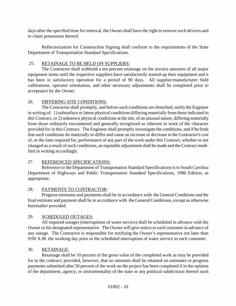
01002 - 10
days after the specified time for removal, the Owner shall have the right to remove such devices and to claim possession thereof.
Reflectorization for Construction Signing shall conform to the requirements of the State Department of Transportation Standard Specifications. 25.
The Contractor shall withhold a ten percent retainage on the invoice amounts of all major equipment items until the respective suppliers have satisfactorily started-up their equipment and it has been in satisfactory operation for a period of 90 days. All supplier/manufacturer field calibrations, operator orientation, and other necessary adjustments shall be completed prior to acceptance by the Owner.
RETAINAGE TO BE HELD ON SUPPLIERS:
26.
The Contractor shall promptly, and before such conditions are disturbed, notify the Engineer in writing of: 1) subsurface or latent physical conditions differing materially from those indicated in this Contract, or 2) unknown physical conditions at the site, of an unusual nature, differing materially from those ordinarily encountered and generally recognized as inherent in work of the character provided for in this Contract. The Engineer shall promptly investigate the conditions, and if he finds that such conditions do materially so differ and cause an increase or decrease in the Contractor's cost of, or the time required for, performance of any part of the work under this Contract, whether or not changed as a result of such conditions, an equitable adjustment shall be made and the Contract modi-fied in writing accordingly.
DIFFERING SITE CONDITIONS:
27. REFERENCED SPECIFICATIONS:
Reference to the Department of Transportation Standard Specifications is to South Carolina Department of Highways and Public Transportation Standard Specifications, 1986 Edition, as appropriate.
28. PAYMENTS TO CONTRACTOR
Progress estimates and payments shall be in accordance with the General Conditions and the final estimate and payment shall be in accordance with the General Conditions, except as otherwise hereinafter provided.
:
29.
All required outages (interruptions of water service) shall be scheduled in advance with the Owner or his designated representative. The Owner will give notice to each customer in advance of any outage. The Contractor is responsible for notifying the Owner’s representative not later than 9:00 A.M. the working day prior to the scheduled interruption of water service to each customer.
SCHEDULED OUTAGES:
30. RETAINAGE
Retainage shall be 10 percent of the gross value of the completed work as may be provided for in the contract; provided, however, that no amounts shall be retained on estimates or progress payments submitted after 50 percent of the work on the project has been completed if in the opinion of the department, agency, or instrumentality of the state or any political subdivision thereof such
:

01002 - 11
work is satisfactory and has been completed on schedule. This will not affect the retained amounts on the first 50 percent of the work on the project which may continue to be held to ensure satisfactory completion of the project. If, after discontinuing the retention, the department, agency, or instrumentality of the state or any political subdivision thereof determines that the work is unsatisfactory or has fallen behind schedule, retention may be resumed at the previous level. Retainage shall be invested at the current market rate and any interest earned on the retained amount by such department, agency, or instrumentality of the state or any political subdivision of the state shall be paid to the contractor when the project has been completed within the time limits specified and for the price specified in the contract, or in any amendments or change orders approved in accord with the terms of the contract, as certified pursuant to subsection (b) of this Code section.
Final payment of the retained amounts to the contractor under the contract to which the retained amounts relate shall be made after certification by the Engineer in charge of the project covered by the contract that the work has been satisfactorily completed and is accepted in accordance with the contract, plans, and specifications. Payment to the contractor of interest earned on the retained amounts shall be made after certification by the Engineer in charge of the project covered by the contract that the work has been completed within the time specified and within the price specified in the contract.
At substantial completion of the work and as the governmental entity’s authorized contract representative determines the work to be reasonably satisfactory, the governmental entity shall within 30 days after invoice and other appropriate documentation as may be required by the contract documents are provided pay the retainage to the contractor. If at that time there are any remaining incomplete minor items, an amount equal to 200 percent of the value of each item as determined by the governmental entity’s authorized contract representative shall be withheld until such item or items are completed. 31. PERMITS
The contractor shall comply with all terms, conditions and requirements of the permits which the Owner has obtained for construction of the project.
:
32.
Complete “record data” information shall be submitted by the Contractor to the Engineer along with the final pay request. “Record data” information shall include elevations of tops and inverts of all sanitary sewer structures and length and size of all pipes, locations of all structures, valves, hydrants and service laterals. Final payment shall not be approved prior to the Engineer receiving the required “record data” information from the Contractor.
RECORD DATA:
33.
INSURANCE:
II. Insurance Requirements.
1. Commercial General Liability Insurance: The Contractor shall take out and maintain during the life of the contract such commercial general liability insurance as shall protect him from claims for damage for bodily injury,

01002 - 12
including accidental death, as well as from claims for property damage, which may arise from operation under this contract whether such operations are by himself or by any SUBCONTRACTOR or by anyone directly or indirectly employed by either of them. The amount of such insurance shall be not less than the following:
General Aggregate
$2,000,000.00
Products - Complete/Operations Aggregate
$2,000,000.00
Personal and Advertising Injury
$1,000,000.00
Each Occurrence
$1,000,000.00
Fire Damage (Any one fire)
$50,000.00
Medical Expenses (any one person)
$5,000.00
a. The General Aggregate listed above shall be for this project only. b. Special Hazards: The CONTRACTOR’S and his
SUBCONTRACTOR’S General Liability Insurance shall provide adequate protection against use of explosives, collapse, and underground hazards. Each detonation of blasting shall be considered a single occurrence.
2. Comprehensive Automobile Liability Insurance:
a. Includes coverage for all owned, hired and non-owned automobiles. b. The combined single limit of liability shall not be less than the
following:
Any One Accident or Loss
$1,000,000.00
3. Excess Liability (Umbrella) Insurance:
a. CONTRACTOR shall carry and maintain Combined Excess Liability
(Umbrella) insurance for a limit not less than the following:
Each Occurrence
$5,000,000.00
Aggregate
$5,000,000.00
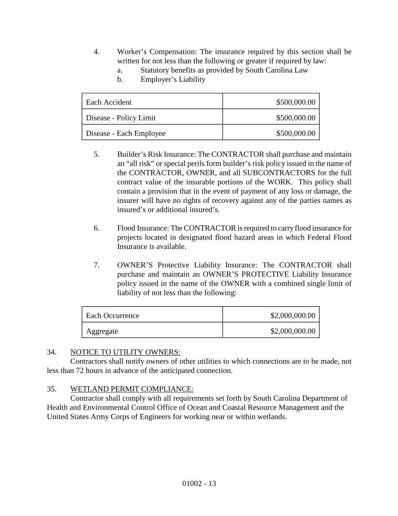
01002 - 13
4. Worker’s Compensation: The insurance required by this section shall be written for not less than the following or greater if required by law: a. Statutory benefits as provided by South Carolina Law b. Employer’s Liability
Each Accident
$500,000.00
Disease - Policy Limit
$500,000.00
Disease - Each Employee
$500,000.00
5. Builder’s Risk Insurance: The CONTRACTOR shall purchase and maintain
an “all risk” or special perils form builder’s risk policy issued in the name of the CONTRACTOR, OWNER, and all SUBCONTRACTORS for the full contract value of the insurable portions of the WORK. This policy shall contain a provision that in the event of payment of any loss or damage, the insurer will have no rights of recovery against any of the parties names as insured’s or additional insured’s.
6. Flood Insurance: The CONTRACTOR is required to carry flood insurance for
projects located in designated flood hazard areas in which Federal Flood Insurance is available.
7. OWNER’S Protective Liability Insurance: The CONTRACTOR shall
purchase and maintain an OWNER’S PROTECTIVE Liability Insurance policy issued in the name of the OWNER with a combined single limit of liability of not less than the following:
Each Occurrence
$2,000,000.00
Aggregate
$2,000,000.00
34.
Contractors shall notify owners of other utilities to which connections are to be made, not less than 72 hours in advance of the anticipated connection.
NOTICE TO UTILITY OWNERS:
35. Contractor shall comply with all requirements set forth by South Carolina Department of Health and Environmental Control Office of Ocean and Coastal Resource Management and the United States Army Corps of Engineers for working near or within wetlands.
WETLAND PERMIT COMPLIANCE:
01002 - 14
36. If the Contractor is a non-resident of South Carolina, it is the burden of the Contractor to complete and file Form I-312 State of South Carolina Department of Revenue Nonresident Taxpayer Registration Affidavit Income Tax Withholding.
NON-RESIDENT OF SOUTH CAROLINA CONTRACTOR:
END OF SECTION
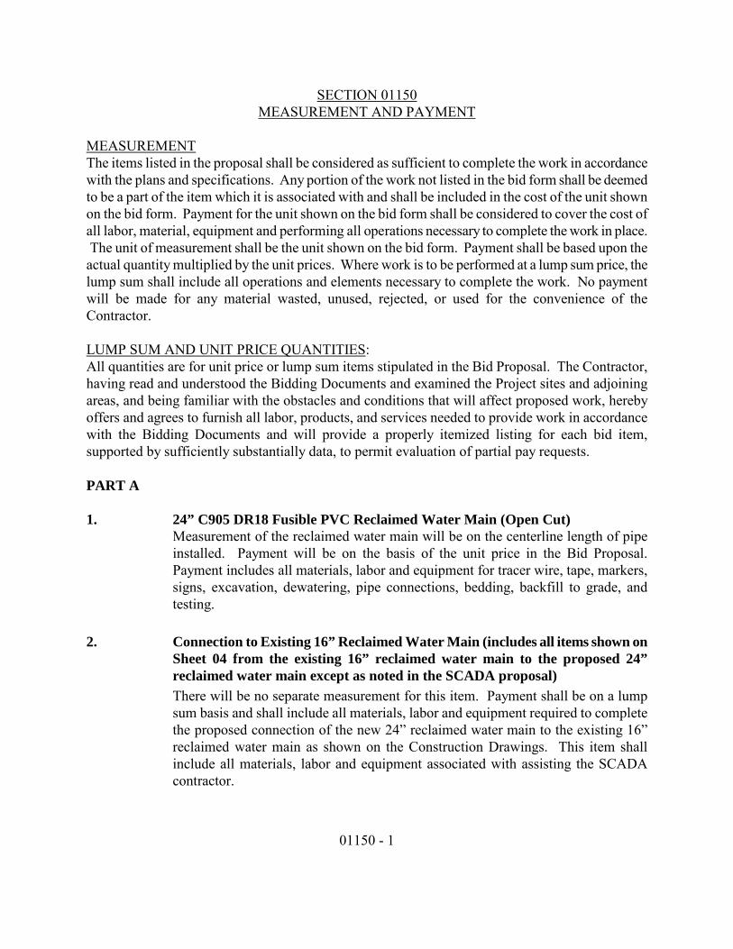
01150 - 1
SECTION 01150
MEASUREMENT AND PAYMENT
The items listed in the proposal shall be considered as sufficient to complete the work in accordance with the plans and specifications. Any portion of the work not listed in the bid form shall be deemed to be a part of the item which it is associated with and shall be included in the cost of the unit shown on the bid form. Payment for the unit shown on the bid form shall be considered to cover the cost of all labor, material, equipment and performing all operations necessary to complete the work in place. The unit of measurement shall be the unit shown on the bid form. Payment shall be based upon the actual quantity multiplied by the unit prices. Where work is to be performed at a lump sum price, the lump sum shall include all operations and elements necessary to complete the work. No payment will be made for any material wasted, unused, rejected, or used for the convenience of the Contractor.
MEASUREMENT
LUMP SUM AND UNIT PRICE QUANTITIESAll quantities are for unit price or lump sum items stipulated in the Bid Proposal. The Contractor, having read and understood the Bidding Documents and examined the Project sites and adjoining areas, and being familiar with the obstacles and conditions that will affect proposed work, hereby offers and agrees to furnish all labor, products, and services needed to provide work in accordance with the Bidding Documents and will provide a properly itemized listing for each bid item, supported by sufficiently substantially data, to permit evaluation of partial pay requests.
:
PART A 1. 24” C905 DR18 Fusible PVC Reclaimed Water Main (Open Cut)
Measurement of the reclaimed water main will be on the centerline length of pipe installed. Payment will be on the basis of the unit price in the Bid Proposal. Payment includes all materials, labor and equipment for tracer wire, tape, markers, signs, excavation, dewatering, pipe connections, bedding, backfill to grade, and testing.
2. Connection to Existing 16” Reclaimed Water Main (includes all items shown on
Sheet 04 from the existing 16” reclaimed water main to the proposed 24” reclaimed water main except as noted in the SCADA proposal) There will be no separate measurement for this item. Payment shall be on a lump sum basis and shall include all materials, labor and equipment required to complete the proposed connection of the new 24” reclaimed water main to the existing 16” reclaimed water main as shown on the Construction Drawings. This item shall include all materials, labor and equipment associated with assisting the SCADA contractor.

01150 - 2
3. SCADA Allowance (See Appendix B) There will be no separate measurement for this item. Payment shall be on a lump sum allowance basis for the materials and work described in the quote in Appendix B from MR Systems, Inc.
4.-8. Air Release Valves, Fittings and Connections to HDD Pipe
Measurement for these items shall be on the basis of completed units in place. Payment for all materials, labor and equipment required for installing items on the basis of the respective unit contract price for each size, type and description listed in the Bid Proposal.
9. Connect Open-Cut Pipe to 12" (including Fittings and Adapters Not Otherwise
Listed for Connection) There will be no separate measurement for this item. Payment shall be on a lump sum basis and shall include all materials, labor and equipment required to complete the proposed connection of the proposed 24” reclaimed water main to the proposed 12” distribution pipe as shown on the Construction Drawings. This item shall include all materials, labor and equipment to install the fittings, valves and gauges as shown on the Construction Drawings.
10.-14. Soil Erosion Control and Remove and Replace Items
Measurement for these items shall be on the basis of completed units in place. Payment for all materials, labor and equipment required for installing items on the basis of the respective unit contract price for each size, type and description listed in the Bid Proposal.
15. Grading, spreading/disposal of excess excavated material, remove and replace
signs/monuments, tree protection, remove and replace fence/gate as needed, mobilization/demobilization, clean-up, insurance, bonds, and other miscellaneous items not specifically listed but necessary for a complete job Measurement for this item shall be on the basis of the completed job. Payment for this item will be on the basis of the lump sum price in the Bid Proposal.
PART B 1. 12” Kroy QS2P PVC Surface (Distribution) Pipe attached to Boardwalk
Measurement of the distribution pipe will be on the centerline length of pipe installed. Payment will be on the basis of the unit price in the Bid Proposal. Payment includes all materials, labor and equipment required for attachment to the boardwalk per the details shown on the Bid Documents.
2. 4’ Distribution Boardwalk
Measurement of the distribution boardwalk will be on the centerline length of
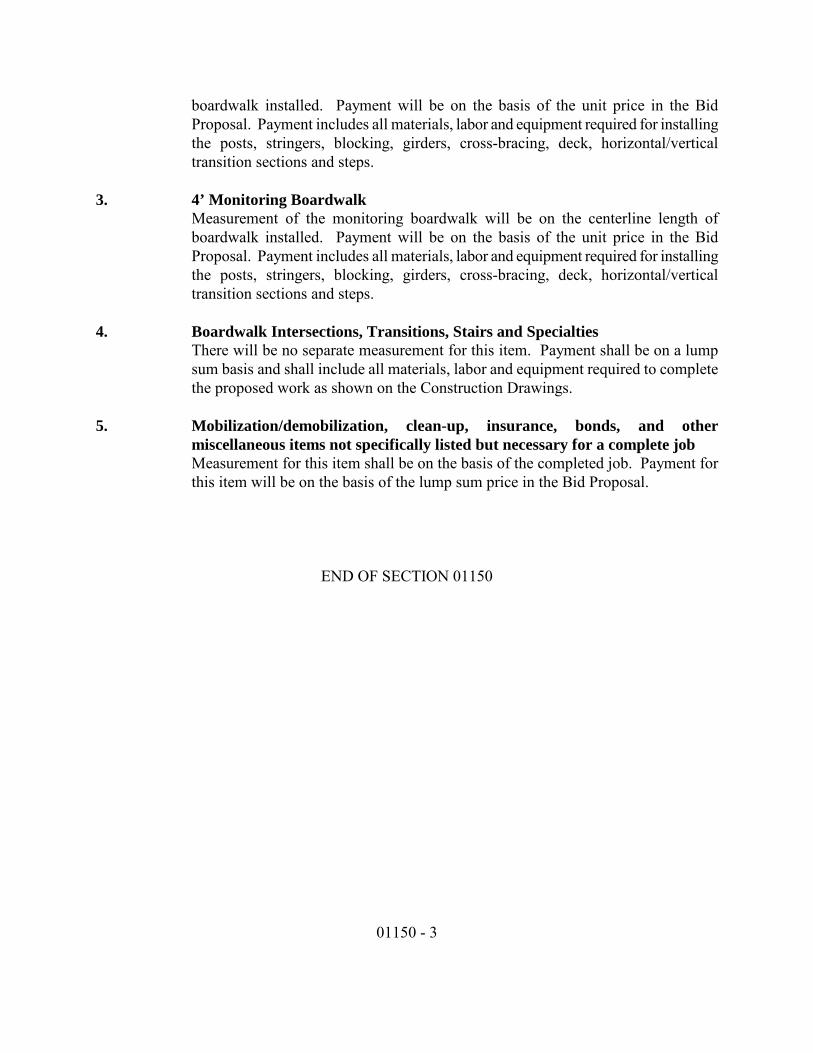
01150 - 3
boardwalk installed. Payment will be on the basis of the unit price in the Bid Proposal. Payment includes all materials, labor and equipment required for installing the posts, stringers, blocking, girders, cross-bracing, deck, horizontal/vertical transition sections and steps.
3. 4’ Monitoring Boardwalk
Measurement of the monitoring boardwalk will be on the centerline length of boardwalk installed. Payment will be on the basis of the unit price in the Bid Proposal. Payment includes all materials, labor and equipment required for installing the posts, stringers, blocking, girders, cross-bracing, deck, horizontal/vertical transition sections and steps.
4. Boardwalk Intersections, Transitions, Stairs and Specialties
There will be no separate measurement for this item. Payment shall be on a lump sum basis and shall include all materials, labor and equipment required to complete the proposed work as shown on the Construction Drawings.
5. Mobilization/demobilization, clean-up, insurance, bonds, and other
miscellaneous items not specifically listed but necessary for a complete job Measurement for this item shall be on the basis of the completed job. Payment for this item will be on the basis of the lump sum price in the Bid Proposal.
END OF SECTION 01150

BEAUFORT-JASPER WATER & SEWER AUTHORITY
TECHNICAL SPECIFICATIONS
REVISED JULY 2009

BJWSA TECHNICAL SPECIFICATIONS REVISED JULY 2009
DHEC APPROVAL PAGE

BJWSA TECHNICAL SPECIFICATIONS REVISED JULY 2009
i
TABLE OF CONTENTS CHAPTER 1 SAFETY DESIGN CONSIDERATIONS ..........................................................................1
CHAPTER 2 EARTHWORK ....................................................................................................................2 2.1 SCOPE:.........................................................................................................................................................2 2.2 GENERAL:...................................................................................................................................................2 2.3 CLEARING AND GRUBBING:..................................................................................................................2 2.4 STRUCTURE EXCAVATION AND BACKFILL: .....................................................................................3 2.5 TRENCH EXCAVATION AND BACKFILL:.............................................................................................4 2.6 SITE GRADING: .........................................................................................................................................6 CHAPTER 3 GRASSING AND SITE RESTORATION ........................................................................8 3.1 SCOPE..........................................................................................................................................................8 3.2 GENERAL....................................................................................................................................................8 3.3 FERTILIZING AND GRASSING...............................................................................................................8 CHAPTER 4 ROADWAY REPAIR AND RESURFACING................................................................10 4.1 AGGREGATE SURFACING: ...................................................................................................................10 4.2 CUTTING AND REPLACING PAVEMENT:..........................................................................................10 4.3 RESURFACING OF EXISTING PAVEMENT: ......................................................................................11 CHAPTER 5 PIPELINE DRILLING, BORING AND JACKING ......................................................13 5.1 SCOPE:.......................................................................................................................................................13 5.2 GENERAL REQUIREMENTS: ................................................................................................................13 5.3 MATERIALS:.............................................................................................................................................13 5.4 INSTALLATION:.......................................................................................................................................14 CHAPTER 6 PIPELINE MATERIALS, VALVES AND APPURTENANCES .................................16 6.1 PIPELINE MATERIALS ..........................................................................................................................16 6.2 VALVES......................................................................................................................................................21 6.3 FITTINGS, APPURTENANCES AND SPECIALTIES: .........................................................................24 CHAPTER 7 WATER SYSTEM STANDARDS....................................................................................29 7.1 SCOPE........................................................................................................................................................29 7.2 WATER SYSTEM DESIGN GUIDELINES:............................................................................................29 7.3 FIRE HYDRANTS AND POST TYPE FLUSHING HYDRANTS:.........................................................30 7.4 POTABLE WATER SERVICE CONNECTIONS: ...................................................................................31 7.5 WATER PIPELINE INSTALLATION: ....................................................................................................33 7.6 PIPELINE TESTING AND DISINFECTION PROCEDURES: ............................................................36 CHAPTER 8 WASTEWATER SYSTEM STANDARDS .....................................................................38 8.1 SCOPE........................................................................................................................................................38 8.2 INSTALLATION GUIDELINES ..............................................................................................................38 8.3 PIPELINE TESTING PROCEDURES.....................................................................................................44 CHAPTER 9 CONCRETE STRUCTURES, MANHOLES AND APPURTENANCES ....................46 9.1 SCOPE........................................................................................................................................................46 9.2 MATERIALS ..............................................................................................................................................46 9.3 TESTS OF STRUCTURES: ......................................................................................................................49 CHAPTER 10 SEWER PUMP STATIONS AND APPURTENANCES..............................................50 10.1 SCOPE........................................................................................................................................................50 10.2 DESIGN CONSIDERATIONS..................................................................................................................50

BJWSA TECHNICAL SPECIFICATIONS REVISED JULY 2009
ii
10.3 PUMPS AND MOTORS ............................................................................................................................54 10.4 TESTING AND STARTUP........................................................................................................................57 10.5 CLOSEOUT REQUIREMENTS ...............................................................................................................58 CHAPTER 11 ELECTRICAL .................................................................................................................59 11.1 GENERAL..................................................................................................................................................59 11.2 MAIN CONTROL PANEL ........................................................................................................................60 11.3 SUBMERSIBLE PUMP STATIONS ........................................................................................................62 11.4 ABOVE GROUND SUCTION LIFT PUMP STATION...........................................................................63 11.5 QUALITY ASSURANCE ...........................................................................................................................63 11.6 SUBMITTALS............................................................................................................................................63 11.7 PRODUCTS/MATERIALS........................................................................................................................63 11.8 INSTALLATION........................................................................................................................................64 11.9 ELECTRICAL SPARE PARTS .................................................................................................................64 CHAPTER 12 PUMP STATION SCADA SYSTEMS...........................................................................65 12.1 SCADA DEFINITIONS.............................................................................................................................65 12.2 SCADA I/O .................................................................................................................................................66 CHAPTER 13 APPROVED MANUFACTURERS................................................................................68 13.1 GENERAL..................................................................................................................................................68 13.2 PUMP STATIONS .....................................................................................................................................72 13.3 SEWER .......................................................................................................................................................75 13.4 WATER.......................................................................................................................................................77 APPENDIX A – GENERAL STANDARD DETAIL DRAWINGS.......................................................A
APPENDIX B – WASTEWATER/SEWER STANDARD DETAIL DRAWINGS..............................B
APPENDIX C – WATER STANDARD DETAIL DRAWINGS............................................................C
APPENDIX D – SAFETY STANDARD DETAIL DRAWINGS...........................................................D
BJWSA TECHNICAL SPECIFICATIONS REVISED JULY 2009
CHAPTER 1 SAFETY 1
CHAPTER 1 SAFETY DESIGN CONSIDERATIONS
Reserved for Safety Chapter
END OF SECTION
BJWSA TECHNICAL SPECIFICATIONS REVISED JULY 2009
CHAPTER 2 EARTHWORK 2
CHAPTER 2 EARTHWORK
2.1 SCOPE:
Earthwork shall consist of all necessary site clearing and grubbing, excavation and backfill for structures and trenches, site grading, grassing and restoration, as well as related work as shown on the plans and as specified herein.
2.2 GENERAL:
All earthwork shall be confined to the construction area as shown on the plans, and shall be done in an approved manner with proper equipment. Earthwork shall be suspended during rain and inclement weather, or when unsatisfactory field conditions are encountered, unless otherwise directed by the ENGINEER. At all times during construction, the CONTRACTOR shall maintain proper drainage in the construction area, and shall take all measures necessary for erosion and sediment control. A. Classification of earthwork: All excavation will be unclassified, for payment purposes,
unless otherwise specified. B. Existing Utilities: CONTRACTOR shall take every precaution to protect existing utility
services from damage during construction operations. If damage occurs, the OWNER of the utility shall be notified immediately and repairs shall be made promptly at the CONTRACTOR’S expense. All repair work shall be satisfactory to the ENGINEER and the OWNER of the utility. When interruptions of existing utilities occur, temporary service shall be provided as approved by the ENGINEER and OWNER of the utility.
2.3 CLEARING AND GRUBBING:
A. General: 1. The CONTRACTOR shall consult with the OWNER and ENGINEER prior to
beginning clearing, and a full understanding is to be reached as to procedure. The CONTRACTOR shall then conduct clearing and grubbing operations in strict accordance with these agreements.
2. The CONTRACTOR’S operations shall be conducted with full consideration of all proper and legal rights of the OWNER, adjacent property OWNER’S and the public, and with the least possible amount of inconvenience to them.
B. Construction Sites: The work shall consist of clearing and grubbing within the limits of construction sites, road rights-of-way and elsewhere as indicated or necessary to complete the work, except pipelines. All trees, stumps, roots, shrubs and brush shall be removed as required for construction. Stumps and roots shall be grubbed and completely removed. The resulting depressions shall be filled with suitable material placed and compacted in accordance with Chapter 3, “Grassing and Site Restoration”. Sound trees and shrubs, which do not interfere with construction, shall remain in place and shall be adequately protected from damage. Cleared and grubbed material, including debris and rubbish, shall be completely burned or otherwise disposed of as directed by the ENGINEER.
C. Pipelines: Clearing and grubbing along pipelines shall be done prior to pipe installation, and shall be confined to the right-of-way limits as specified below. Adjacent property outside the right-of-way limits shall be protected against damage. All trees, stumps, roots, shrubs, and brush shall be removed as required for construction. Stumps and roots shall be grubbed and completely removed. Sound trees and shrubs, which do not interfere with

BJWSA TECHNICAL SPECIFICATIONS REVISED JULY 2009
CHAPTER 2 EARTHWORK 3
construction, shall remain in place and shall be adequately protected from damage. Cleared and grubbed material, including debris and rubbish, shall be disposed of as directed by the ENGINEER; burning within pipeline rights-of-way will not be allowed.
1. Trees 6-inches and larger in diameter shall be trimmed into normal 63-inch lengths, unless otherwise directed by the property OWNER. The logs shall be neatly stacked along the edge of the right-of-way in accessible locations for the property OWNER’S use.
2. Limits of the pipe-laying operation shall be confined to the right-of-way. The width of clearing shall be held to a minimum and shall be no more than specified on the plans, without written consent of the ENGINEER.
D. Structures: Minor structures shall be removed and disposed of as directed by the ENGINEER.
E. Burning: Burning of Cleared Material shall be accomplished in strict compliance with all applicable local, state and federal regulations pertaining to open burning and smoke abatement.
2.4 STRUCTURE EXCAVATION AND BACKFILL:
A. General: Excavations shall be in compliance with current OSHA regulations. Structure Excavation shall be made to the elevations, slopes and limits shown on the plans. Bottom of excavations shall be level and in firm, solid material; where soft or otherwise unsuitable material is encountered, such material shall be removed and replaced with properly compacted earth material, stone or flowable fill, as directed by the ENGINEER. Topsoil and other excavated material suitable for fill or backfill shall be stockpiled on the site for future use. Excess material and unsuitable material shall be properly disposed of. Excavated areas shall be kept free of water during construction. Where necessary, excavations shall be protected by shoring, sheeting, cofferdams or other suitable methods. Where earth will stand, footing trenches may be cut to the exact size of the footings; otherwise, forms shall be used.
1. Unauthorized or excessive excavation shall be corrected by providing properly compacted earth backfill, stone or Class C concrete, as directed by the ENGINEER, at the CONTRACTOR’S expense.
2. Wherever excavation for a foundation extends below the water table or where specifically indicated on the plans, a 12-inch layer (unless otherwise noted) of crushed stone or gravel shall be spread and compacted in the excavation bottom prior to placing the foundation. Crushed stone or gravel shall conform to ASTM C33, Size 57. A non-woven filter fabric, Mirafi 140N or equivalent shall be placed beneath the stone layer.
3. An adequate dewatering system shall be provided at all structure excavations and elsewhere as directed by the ENGINEER. The system shall be capable of removing any water that accumulates in the excavation and maintaining the excavation in a dry condition while construction is in progress. The surface of the ground shall be sloped away from the excavation or piping provided to prevent surface water from entering the excavation. Disposal of water resulting from the dewatering operation shall be done in a manner that does not interfere with normal drainage, and does not cause damage to any portion of the work or adjacent property. All drains, culverts, storm sewers and inlets subject to the dewatering operation shall be kept clean and open for normal surface drainage. The dewatering system shall be maintained until backfilling is complete or as otherwise directed by the ENGINEER. All damages resulting from the dewatering operation shall be repaired by the CONTRACTOR to the satisfaction of the
BJWSA TECHNICAL SPECIFICATIONS REVISED JULY 2009
CHAPTER 2 EARTHWORK 4
ENGINEER and at no cost to the OWNER. 4. Limit of structure excavation, for payment purposes, shall be 3 FT from the outside wall
line of structures. Material removed beyond this limit to facilitate work shall be at the CONTRACTOR’S expense.
B. Backfill Around Structures: Backfill around structures shall be placed as soon as possible, but not until construction below finish grade has been completed and accepted, underground piping and other utilities have been properly installed and tested, forms have been removed, and the excavation cleaned of trash and debris. Foundations and walls shall be braced and supported as required to withstand the forces imposed by the backfilling operation. Care shall be taken to protect piping and other utilities during backfill.
1. Backfill shall consist of suitable material from the excavation free of roots, wood, other vegetable matter, trash, debris, frozen material, rocks larger than 4 inches in any dimension, and other objectionable material. Backfill shall be brought to the indicated finish grade and sloped to drain away from walls. Backfill shall be placed in 8-inch layers and thoroughly compacted as specified below. Any subsequent settlement that may occur during the construction period shall be corrected.
2. Excessively wet, porous, spongy or mucky material shall be removed from around structures prior to placing backfill. No such material shall be used for backfill.
3. Unless otherwise directed by the ENGINEER, liquid-retaining structures shall not be backfilled until tested for leakage and accepted. All structures shall be protected against damage or flotation prior to placing backfill.
2.5 TRENCH EXCAVATION AND BACKFILL:
A. Pipe Bedding and Backfill Material: Select material shall be material free of large stones, hard lumps, frozen matter, organic material, debris and other objectionable material. If necessary, suitable material shall be provided by the CONTRACTOR from other sources at CONTRACTOR’s expense. All material from the excavation unsuitable for bedding and backfill shall be removed and disposed of by the CONTRACTOR. Angular Material shall be crushed stone or gravel conforming to ASTM C33, Size No. 57, with size range of ¼ to ¾-inch.
B. Trench Excavation: ALL EXCAVATION SHALL BE IN COMPLIANCE WITH CURRENT OSHA REQUIREMENTS. Trenches for pipe and other utilities shall be excavated true to line and grade. Unless otherwise indicated or specified, trenches shall be of a depth to provide a minimum cover of 3 FT over the top of pipelines.
1. Sidewalls of trenches shall comply with current OSHA requirements. Unless otherwise specified, trenches shall be between 12 and 18 inches wider than the outside diameter of the pipe, plus sheeting where necessary. Pavement shall be cut 12 inches wider than the required trench width on each side. For gravity sewer lines the maximum trench width shall be up to a level 12 inches above the top of the pipe or shall be as noted on the plans. Sheeting or shoring shall be used where necessary.
2. Where soil conditions preclude vertical walls, the trench width shall be as specified above with the upper part of the trench limited to the least possible width greater than that specified. Where excessive trench widths are necessary, or where directed by the ENGINEER, sheeting or shoring shall be used to support trench walls.
3. Pressure Pipelines: For pressure pipelines, prepare trench bottoms as follows: a) Trench bottoms shall be graded to provide uniform and continuous bearing for the
pipe along its entire length. Bell holes shall be provided for completion of joints. No ridges, sags or undercutting will be allowed.

BJWSA TECHNICAL SPECIFICATIONS REVISED JULY 2009
CHAPTER 2 EARTHWORK 5
b) If approved by the ENGINEER and subject to suitable soil conditions, trenches may be excavated a few inches below the established subgrade and backfilled to subgrade with select material, well compacted and graded to provide uniform and continuous bearing for the entire length of pipe. Bedding material shall be well compacted up to the springline of the pipe, shovel sliced and shaped so that the load is supported throughout the entire length of pipe barrel and not at the pipe bells. Bell holes shall be provided for completion of joints.
c) In rock or other unyielding material, excavation shall be made at least 6”below the established subgrade and the trench backfilled to subgrade with select material. Bedding material shall be well compacted up to the springline of the pipe, shovel sliced and shaped so that the load is supported throughout the entire length of pipe barrel and not at the pipe bells.
d) Where material at subgrade is unstable, soft and incapable of supporting the pipe, trenches shall be excavated below subgrade to a depth as required by soil conditions, and backfilled to subgrade with angular material. The material shall be compacted and graded to provide a stable foundation and uniform bearing for the pipe. Bedding material shall be well compacted up to the springline of the pipe, shovel sliced and shaped so that the load is supported throughout the entire length of pipe barrel and not at the pipe bells.
e) Debris encountered in trench excavation for water and other pipelines shall be removed for the overall width of the trench. It shall be removed to a depth of 6” below the bottom of the pipe for pipes smaller than 24” in size; 8” below the bottom of the pipe for pipes 24” to 36” in size; and 12” below the bottom of the pipe for pipes larger than 36” in size, if debris extends to such depth.
4. Pipe on Grade Pipelines: For gravity sewer lines, prepare trench bottoms as follows: a) Trenches shall be excavated below the established subgrade as required to provide
for preparation of flat trench bottoms in strict accordance with the trench bedding details as shown. Pipe backfill shall be #57 stone unless specifically noted on the plans or where directed by the ENGINEER.
b) Angular material consisting of #57 stone shall be used for sewer pipe bedding. Excavation below pipe shall be to a minimum depth of 4” or as required to obtain suitable pipe foundation. Overcutting of the trench shall be bedded with crushed stone. Bedding material shall be well compacted up to the springline of the pipe, shovel sliced and shaped so that the load is supported throughout the entire length of pipe barrel and not at the pipe bells. Angular material shall meet the requirements of the SCDOT specification 406.08. Stone size shall be No. 57. The use of fossil limestone will not be allowed.
c) Soft, unstable or otherwise unsuitable material encountered below the normal bedding depth shown on the plans shall be removed and backfilled with crushed stone. All such unsuitable material shall be disposed of by the CONTRACTOR. The depth of cut below the normal bedding depth shall be kept to a minimum, but shall be as required to provide a suitable pipe foundation as directed by the ENGINEER.
5. Trenches shall be kept free of water during pipe installation. Water shall be removed from trenches and disposed of by the CONTRACTOR to the satisfaction of the ENGINEER.
6. Where required, and as approved by the ENGINEER, sheeting, shoring and bracing shall be used to comply with current OSHA requirements and to prevent injury to personnel and caving of trench walls. Sheeting, shoring and bracing shall be left in

BJWSA TECHNICAL SPECIFICATIONS REVISED JULY 2009
CHAPTER 2 EARTHWORK 6
place until the trench is refilled to a safe limit. A trench box may be used if trench widths do not exceed the maximum indicated in the pipe bedding details.
C. Trench Backfill: Trench Backfill shall progress as rapidly as pipe laying and testing will permit. The remainder of the backfill material shall be placed as specified below. No debris or rocks larger than 2 inches in any dimension shall be used in this portion of the backfill.
1. Paved Roads and Streets: Backfill shall be flowable fill, which shall extend beyond pavement edge at least 4 feet.
2. In unpaved roads / shoulders within 5’ of the tread line, backfill shall be placed in layers not more than 8 inches thick, and thoroughly compacted with mechanical tampers to 95% of maximum as determined by the Standard Proctor test (ASTM D698) or Modified Proctor test (ASTM D1557, Method A). On road shoulders, the top 18 inches of the trench shall be filled with well-compacted fill.
3. For cross-country lines, outfall lines and at other locations where damage to the system or property will not occur, backfill shall be placed in 12-inch layers and compacted with mechanical tampers. The upper 3 FT portion of the backfill may be compacted by rolling with wheeled equipment.
4. Tops of trenches shall be flush with existing ground elevation. The CONTRACTOR shall, promptly correct all settlement below finish grade occurring as a result of construction. Trenches shall be protected against scour due to surface drainage.
5. Backfilling around manholes shall, in general, conform to the requirements for backfilling trenches, except that backfill shall not be placed around manholes until all mortar has properly set.
6. CONTRACTOR shall correct any future settlement within the warranty period.
2.6 SITE GRADING:
Site grading shall conform to the lines and grades indicated by the finish contours on the plans. Where topsoil, pavement, aggregate surfacing, and other items are shown, rough grade shall be finished to such depth below finish grade as necessary to accommodate these items. All areas where structures are to be built on fill shall be stripped to such depth as necessary to remove turf, roots, organic matter and other objectionable materials. A. Excavation: Excavation shall be made to the exact elevations, slopes, and limits shown on
the plans. B. Fill: Material to be used for fill shall be classified as “ML” (low plasticity silts), “SM”
(silty sands), or better, in accordance with the Unified Soil Classification System. Fill material shall exhibit a plasticity index of less than 20 and a standard Proctor maximum dry density greater than 90 pounds per cubic foot. Fill shall not contain organic material, debris, or rock larger than 6 inches in any dimension.
1. Where fill is to be placed all existing vegetation, roots and other organic matter down to 12 inches below grade shall be stripped and disposed of as directed.
2. Fill shall be placed in successive layers of not more than 8 inches loose thickness. Each layer shall be spread evenly and compacted as specified below before the next layer is placed.
3. Rock shall not be incorporated in fill sections supporting pavement or structures. Rock shall be evenly distributed. Rock larger than 4 inches in any dimension will not be allowed in the top 12 inches of fills or slopes. Voids between rock material shall be well filled with suitable fill material, and all rock shall be covered with at least 6 inches of fill material.
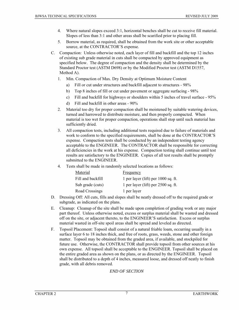
BJWSA TECHNICAL SPECIFICATIONS REVISED JULY 2009
CHAPTER 2 EARTHWORK 7
4. Where natural slopes exceed 3:1, horizontal benches shall be cut to receive fill material. Slopes of less than 3:1 and other areas shall be scarified prior to placing fill.
5. Borrow material, as required, shall be obtained from the work site or other acceptable source, at the CONTRACTOR’S expense.
C. Compaction: Unless otherwise noted, each layer of fill and backfill and the top 12 inches of existing sub grade material in cuts shall be compacted by approved equipment as specified below. The degree of compaction and the density shall be determined by the Standard Proctor test (ASTM D698) or by the Modified Proctor test (ASTM D1557, Method A).
1. Min. Compaction of Max. Dry Density at Optimum Moisture Content a) Fill or cut under structures and backfill adjacent to structures - 98% b) Top 8 inches of fill or cut under pavement or aggregate surfacing - 98% c) Fill and backfill for highways or shoulders within 5 inches of travel surface - 95% d) Fill and backfill in other areas - 90%
2. Material too dry for proper compaction shall be moistened by suitable watering devices, turned and harrowed to distribute moisture, and then properly compacted. When material is too wet for proper compaction, operations shall stop until such material has sufficiently dried.
3. All compaction tests, including additional tests required due to failure of materials and work to conform to the specified requirements, shall be done at the CONTRACTOR’S expense. Compaction tests shall be conducted by an independent testing agency acceptable to the ENGINEER. The CONTRACTOR shall be responsible for correcting all deficiencies in the work at his expense. Compaction testing shall continue until test results are satisfactory to the ENGINEER. Copies of all test results shall be promptly submitted to the ENGINEER.
4. Tests shall be made in randomly selected locations as follows: Material Frequency Fill and backfill 1 per layer (lift) per 1000 sq. ft. Sub grade (cuts) 1 per layer (lift) per 2500 sq. ft. Road Crossings 1 per layer
D. Dressing Off: All cuts, fills and slopes shall be neatly dressed off to the required grade or subgrade, as indicated on the plans.
E. Cleanup: Cleanup of the site shall be made upon completion of grading work or any major part thereof. Unless otherwise noted, excess or surplus material shall be wasted and dressed off on the site, or adjacent thereto, to the ENGINEER’S satisfaction. Excess or surplus material wasted in off-site spoil areas shall be spread and leveled as directed.
F. Topsoil Placement: Topsoil shall consist of a natural friable loam, occurring usually in a surface layer 6 to 18 inches thick, and free of roots, grass, weeds, stone and other foreign matter. Topsoil may be obtained from the graded area, if available, and stockpiled for future use. Otherwise, the CONTRACTOR shall provide topsoil from other sources at his own expense. All topsoil shall be acceptable to the ENGINEER. Topsoil shall be placed on the entire graded area as shown on the plans, or as directed by the ENGINEER. Topsoil shall be distributed to a depth of 4 inches, measured loose, and dressed off neatly to finish grade, with all debris removed.
END OF SECTION
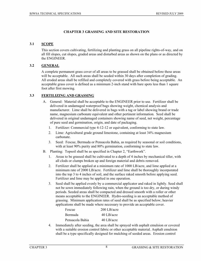
BJWSA TECHNICAL SPECIFICATIONS REVISED JULY 2009
CHAPTER 3 GRASSING & SITE RESTORATION 8
CHAPTER 3 GRASSING AND SITE RESTORATION
3.1 SCOPE
This section covers cultivating, fertilizing and planting grass on all pipeline rights-of-way, and on all fill slopes, cut slopes, graded areas and disturbed areas as shown on the plans or as directed by the ENGINEER.
3.2 GENERAL
A complete permanent grass cover of all areas to be grassed shall be obtained before these areas will be acceptable. All such areas shall be seeded within 30 days after completion of grading. All eroded areas shall be refilled and completely covered with grass before being acceptable. An acceptable grass cover is defined as a minimum 2-inch stand with bare spots less than 1 square foot after first mowing.
3.3 FERTILIZING AND GRASSING
A. General: Material shall be acceptable to the ENGINEER prior to use. Fertilizer shall be delivered in undamaged waterproof bags showing weight, chemical analysis and manufacturer. Lime shall be delivered in bags with a tag or label showing brand or trade name, magnesium carbonate equivalent and other pertinent information. Seed shall be delivered in original undamaged containers showing name of seed, net weight, percentage of pure seed and germination, origin, and date of packaging.
1. Fertilizer: Commercial type 4-12-12 or equivalent, conforming to state law. 2. Lime: Agricultural grade ground limestone, containing at least 34% magnesium
carbonate. 3. Seed: Fescue, Bermuda or Pensacola Bahia, as required by seasonal or soil conditions,
with at least 90% purity and 80% germination, conforming to state law. B. Planting: Topsoil shall be as specified in Chapter 2, “Earthwork”.
1. Areas to be grassed shall be cultivated to a depth of 4 inches by mechanical tiller, with all clods or clumps broken up and foreign material and debris removed.
2. Fertilizer shall be applied at a minimum rate of 1000 LB/acre, and lime applied at a minimum rate of 2000 LB/acre. Fertilizer and lime shall be thoroughly incorporated into the top 3 to 4 inches of soil, and the surface raked smooth before applying seed. Fertilizer and lime may be applied in one operation.
3. Seed shall be applied evenly by a commercial applicator and raked in lightly. Seed shall not be sown immediately following rain, when the ground is too dry, or during windy periods. Seeded areas shall be compacted and dressed smooth with a roller or other means acceptable to the ENGINEER. Hydro-seeding is an acceptable method of grassing. Minimum application rates of seed shall be as specified below; heavier applications shall be made where necessary to provide an acceptable cover.
Fescue 200 LB/acre Bermuda 40 LB/acre Pensacola Bahia 40 LB/acre
4. Immediately after seeding, the area shall be sprayed with asphalt emulsion or covered with a suitable erosion control fabric or other acceptable material. Asphalt emulsion shall be a type specifically designed for mulching of seeded areas. Erosion control
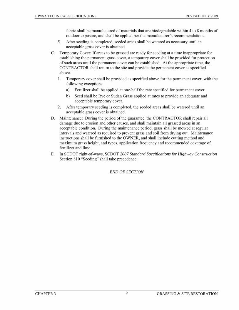
BJWSA TECHNICAL SPECIFICATIONS REVISED JULY 2009
CHAPTER 3 GRASSING & SITE RESTORATION 9
fabric shall be manufactured of materials that are biodegradable within 4 to 8 months of outdoor exposure, and shall be applied per the manufacturer’s recommendations.
5. After seeding is completed, seeded areas shall be watered as necessary until an acceptable grass cover is obtained.
C. Temporary Cover: If areas to be grassed are ready for seeding at a time inappropriate for establishing the permanent grass cover, a temporary cover shall be provided for protection of such areas until the permanent cover can be established. At the appropriate time, the CONTRACTOR shall return to the site and provide the permanent cover as specified above.
1. Temporary cover shall be provided as specified above for the permanent cover, with the following exceptions: a) Fertilizer shall be applied at one-half the rate specified for permanent cover. b) Seed shall be Rye or Sudan Grass applied at rates to provide an adequate and
acceptable temporary cover. 2. After temporary seeding is completed, the seeded areas shall be watered until an
acceptable grass cover is obtained. D. Maintenance: During the period of the guarantee, the CONTRACTOR shall repair all
damage due to erosion and other causes, and shall maintain all grassed areas in an acceptable condition. During the maintenance period, grass shall be mowed at regular intervals and watered as required to prevent grass and soil from drying out. Maintenance instructions shall be furnished to the OWNER, and shall include cutting method and maximum grass height, and types, application frequency and recommended coverage of fertilizer and lime.
E. In SCDOT right-of-ways, SCDOT 2007 Standard Specifications for Highway Construction Section 810 “Seeding” shall take precedence.
END OF SECTION
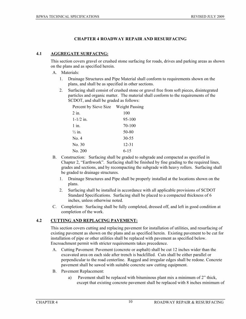
BJWSA TECHNICAL SPECIFICATIONS REVISED JULY 2009
CHAPTER 4 ROADWAY REPAIR & RESURFACING 10
CHAPTER 4 ROADWAY REPAIR AND RESURFACING
4.1 AGGREGATE SURFACING:
This section covers gravel or crushed stone surfacing for roads, drives and parking areas as shown on the plans and as specified herein. A. Materials:
1. Drainage Structures and Pipe Material shall conform to requirements shown on the plans, and shall be as specified in other sections.
2. Surfacing shall consist of crushed stone or gravel free from soft pieces, disintegrated particles and organic matter. The material shall conform to the requirements of the SCDOT, and shall be graded as follows:
Percent by Sieve Size Weight Passing 2 in. 100 1-1/2 in. 95-100 1 in. 70-100 ½ in. 50-80 No. 4 30-55 No. 30 12-31 No. 200 6-15
B. Construction: Surfacing shall be graded to subgrade and compacted as specified in Chapter 2, “Earthwork”. Surfacing shall be finished by fine grading to the required lines, grades and sections, and by recompacting the subgrade with heavy rollers. Surfacing shall be graded to drainage structures.
1. Drainage Structures and Pipe shall be properly installed at the locations shown on the plans.
2. Surfacing shall be installed in accordance with all applicable provisions of SCDOT Standard Specifications. Surfacing shall be placed to a compacted thickness of 6 inches, unless otherwise noted.
C. Completion: Surfacing shall be fully completed, dressed off, and left in good condition at completion of the work.
4.2 CUTTING AND REPLACING PAVEMENT:
This section covers cutting and replacing pavement for installation of utilities, and resurfacing of existing pavement as shown on the plans and as specified herein. Existing pavement to be cut for installation of pipe or other utilities shall be replaced with pavement as specified below. Encroachment permit with stricter requirements takes precedence. A. Cutting Pavement: Pavement (concrete or asphalt) shall be cut 12 inches wider than the
excavated area on each side after trench is backfilled. Cuts shall be either parallel or perpendicular to the road centerline. Ragged and irregular edges shall be redone. Concrete pavement shall be sawed with suitable concrete saw cutting equipment.
B. Pavement Replacement: a) Pavement shall be replaced with bituminous plant mix a minimum of 2” thick,
except that existing concrete pavement shall be replaced with 8 inches minimum of
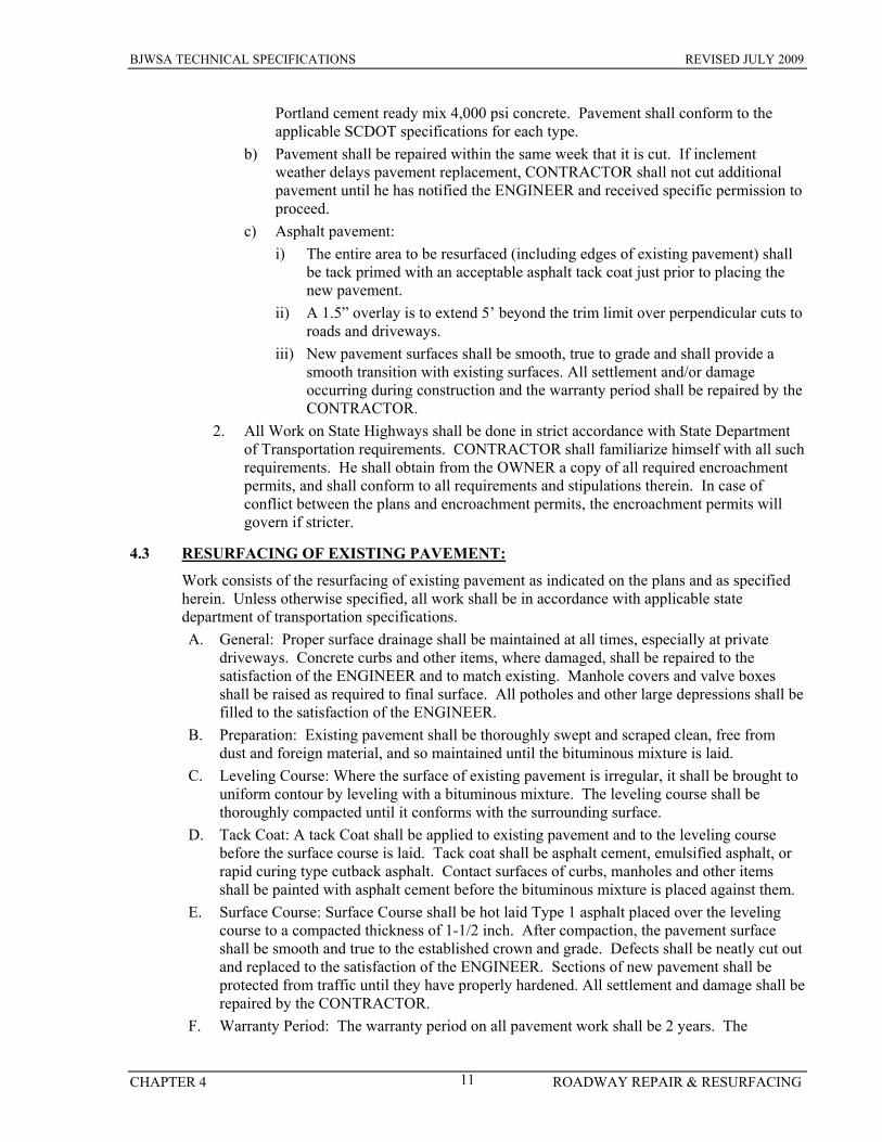
BJWSA TECHNICAL SPECIFICATIONS REVISED JULY 2009
CHAPTER 4 ROADWAY REPAIR & RESURFACING 11
Portland cement ready mix 4,000 psi concrete. Pavement shall conform to the applicable SCDOT specifications for each type.
b) Pavement shall be repaired within the same week that it is cut. If inclement weather delays pavement replacement, CONTRACTOR shall not cut additional pavement until he has notified the ENGINEER and received specific permission to proceed.
c) Asphalt pavement: i) The entire area to be resurfaced (including edges of existing pavement) shall
be tack primed with an acceptable asphalt tack coat just prior to placing the new pavement.
ii) A 1.5” overlay is to extend 5’ beyond the trim limit over perpendicular cuts to roads and driveways.
iii) New pavement surfaces shall be smooth, true to grade and shall provide a smooth transition with existing surfaces. All settlement and/or damage occurring during construction and the warranty period shall be repaired by the CONTRACTOR.
2. All Work on State Highways shall be done in strict accordance with State Department of Transportation requirements. CONTRACTOR shall familiarize himself with all such requirements. He shall obtain from the OWNER a copy of all required encroachment permits, and shall conform to all requirements and stipulations therein. In case of conflict between the plans and encroachment permits, the encroachment permits will govern if stricter.
4.3 RESURFACING OF EXISTING PAVEMENT:
Work consists of the resurfacing of existing pavement as indicated on the plans and as specified herein. Unless otherwise specified, all work shall be in accordance with applicable state department of transportation specifications. A. General: Proper surface drainage shall be maintained at all times, especially at private
driveways. Concrete curbs and other items, where damaged, shall be repaired to the satisfaction of the ENGINEER and to match existing. Manhole covers and valve boxes shall be raised as required to final surface. All potholes and other large depressions shall be filled to the satisfaction of the ENGINEER.
B. Preparation: Existing pavement shall be thoroughly swept and scraped clean, free from dust and foreign material, and so maintained until the bituminous mixture is laid.
C. Leveling Course: Where the surface of existing pavement is irregular, it shall be brought to uniform contour by leveling with a bituminous mixture. The leveling course shall be thoroughly compacted until it conforms with the surrounding surface.
D. Tack Coat: A tack Coat shall be applied to existing pavement and to the leveling course before the surface course is laid. Tack coat shall be asphalt cement, emulsified asphalt, or rapid curing type cutback asphalt. Contact surfaces of curbs, manholes and other items shall be painted with asphalt cement before the bituminous mixture is placed against them.
E. Surface Course: Surface Course shall be hot laid Type 1 asphalt placed over the leveling course to a compacted thickness of 1-1/2 inch. After compaction, the pavement surface shall be smooth and true to the established crown and grade. Defects shall be neatly cut out and replaced to the satisfaction of the ENGINEER. Sections of new pavement shall be protected from traffic until they have properly hardened. All settlement and damage shall be repaired by the CONTRACTOR.
F. Warranty Period: The warranty period on all pavement work shall be 2 years. The
BJWSA TECHNICAL SPECIFICATIONS REVISED JULY 2009
CHAPTER 4 ROADWAY REPAIR & RESURFACING 12
warranty period starts upon acceptance by the governing body or final acceptance by BJWSA, if not under the jurisdiction of a governing body.
END OF SECTION
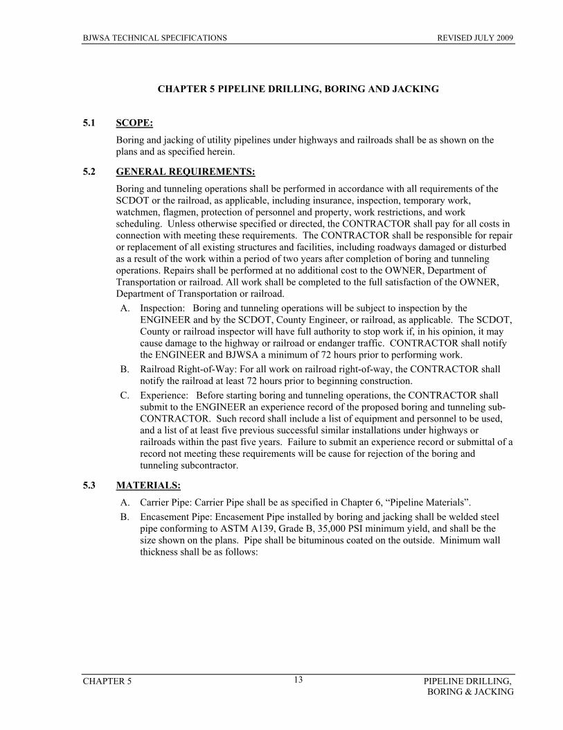
BJWSA TECHNICAL SPECIFICATIONS REVISED JULY 2009
CHAPTER 5 PIPELINE DRILLING, BORING & JACKING
13
CHAPTER 5 PIPELINE DRILLING, BORING AND JACKING
5.1 SCOPE:
Boring and jacking of utility pipelines under highways and railroads shall be as shown on the plans and as specified herein.
5.2 GENERAL REQUIREMENTS:
Boring and tunneling operations shall be performed in accordance with all requirements of the SCDOT or the railroad, as applicable, including insurance, inspection, temporary work, watchmen, flagmen, protection of personnel and property, work restrictions, and work scheduling. Unless otherwise specified or directed, the CONTRACTOR shall pay for all costs in connection with meeting these requirements. The CONTRACTOR shall be responsible for repair or replacement of all existing structures and facilities, including roadways damaged or disturbed as a result of the work within a period of two years after completion of boring and tunneling operations. Repairs shall be performed at no additional cost to the OWNER, Department of Transportation or railroad. All work shall be completed to the full satisfaction of the OWNER, Department of Transportation or railroad. A. Inspection: Boring and tunneling operations will be subject to inspection by the
ENGINEER and by the SCDOT, County Engineer, or railroad, as applicable. The SCDOT, County or railroad inspector will have full authority to stop work if, in his opinion, it may cause damage to the highway or railroad or endanger traffic. CONTRACTOR shall notify the ENGINEER and BJWSA a minimum of 72 hours prior to performing work.
B. Railroad Right-of-Way: For all work on railroad right-of-way, the CONTRACTOR shall notify the railroad at least 72 hours prior to beginning construction.
C. Experience: Before starting boring and tunneling operations, the CONTRACTOR shall submit to the ENGINEER an experience record of the proposed boring and tunneling sub-CONTRACTOR. Such record shall include a list of equipment and personnel to be used, and a list of at least five previous successful similar installations under highways or railroads within the past five years. Failure to submit an experience record or submittal of a record not meeting these requirements will be cause for rejection of the boring and tunneling subcontractor.
5.3 MATERIALS:
A. Carrier Pipe: Carrier Pipe shall be as specified in Chapter 6, “Pipeline Materials”. B. Encasement Pipe: Encasement Pipe installed by boring and jacking shall be welded steel
pipe conforming to ASTM A139, Grade B, 35,000 PSI minimum yield, and shall be the size shown on the plans. Pipe shall be bituminous coated on the outside. Minimum wall thickness shall be as follows:
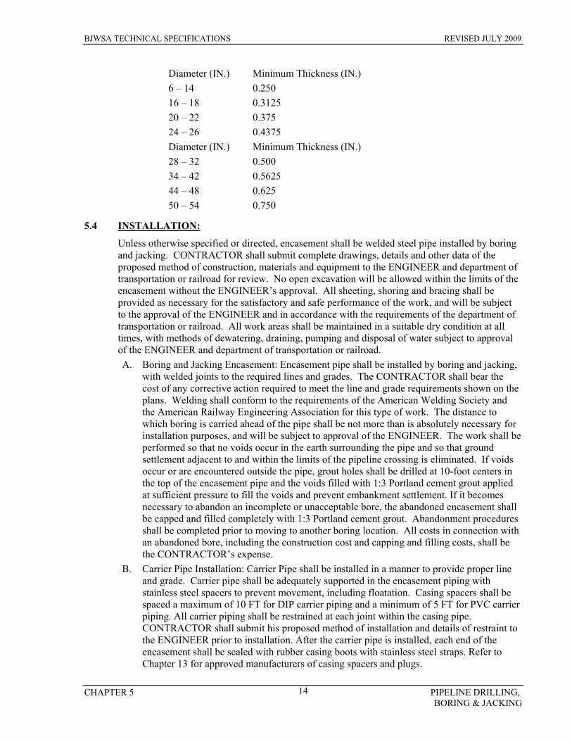
BJWSA TECHNICAL SPECIFICATIONS REVISED JULY 2009
CHAPTER 5 PIPELINE DRILLING, BORING & JACKING
14
Diameter (IN.) Minimum Thickness (IN.) 6 – 14 0.250 16 – 18 0.3125 20 – 22 0.375 24 – 26 0.4375 Diameter (IN.) Minimum Thickness (IN.) 28 – 32 0.500 34 – 42 0.5625 44 – 48 0.625 50 – 54 0.750
5.4 INSTALLATION:
Unless otherwise specified or directed, encasement shall be welded steel pipe installed by boring and jacking. CONTRACTOR shall submit complete drawings, details and other data of the proposed method of construction, materials and equipment to the ENGINEER and department of transportation or railroad for review. No open excavation will be allowed within the limits of the encasement without the ENGINEER’s approval. All sheeting, shoring and bracing shall be provided as necessary for the satisfactory and safe performance of the work, and will be subject to the approval of the ENGINEER and in accordance with the requirements of the department of transportation or railroad. All work areas shall be maintained in a suitable dry condition at all times, with methods of dewatering, draining, pumping and disposal of water subject to approval of the ENGINEER and department of transportation or railroad. A. Boring and Jacking Encasement: Encasement pipe shall be installed by boring and jacking,
with welded joints to the required lines and grades. The CONTRACTOR shall bear the cost of any corrective action required to meet the line and grade requirements shown on the plans. Welding shall conform to the requirements of the American Welding Society and the American Railway Engineering Association for this type of work. The distance to which boring is carried ahead of the pipe shall be not more than is absolutely necessary for installation purposes, and will be subject to approval of the ENGINEER. The work shall be performed so that no voids occur in the earth surrounding the pipe and so that ground settlement adjacent to and within the limits of the pipeline crossing is eliminated. If voids occur or are encountered outside the pipe, grout holes shall be drilled at 10-foot centers in the top of the encasement pipe and the voids filled with 1:3 Portland cement grout applied at sufficient pressure to fill the voids and prevent embankment settlement. If it becomes necessary to abandon an incomplete or unacceptable bore, the abandoned encasement shall be capped and filled completely with 1:3 Portland cement grout. Abandonment procedures shall be completed prior to moving to another boring location. All costs in connection with an abandoned bore, including the construction cost and capping and filling costs, shall be the CONTRACTOR’s expense.
B. Carrier Pipe Installation: Carrier Pipe shall be installed in a manner to provide proper line and grade. Carrier pipe shall be adequately supported in the encasement piping with stainless steel spacers to prevent movement, including floatation. Casing spacers shall be spaced a maximum of 10 FT for DIP carrier piping and a minimum of 5 FT for PVC carrier piping. All carrier piping shall be restrained at each joint within the casing pipe. CONTRACTOR shall submit his proposed method of installation and details of restraint to the ENGINEER prior to installation. After the carrier pipe is installed, each end of the encasement shall be sealed with rubber casing boots with stainless steel straps. Refer to Chapter 13 for approved manufacturers of casing spacers and plugs.

BJWSA TECHNICAL SPECIFICATIONS REVISED JULY 2009
CHAPTER 5 PIPELINE DRILLING, BORING & JACKING
15
C. Directional Drilling: Where directionally drilled (without casing) pipe under highways or railroads is indicated and permitted, the bore diameter shall be essentially the same as the outside diameter of the pipe to prevent settlement or caving. All borings under public roads shall comply with SCDOT regulations. If voids develop or if the bore diameter is greater than the outside diameter of the pipe by more than 1 inch, the voids shall be pressure grouted or other remedial measures as approved by the ENGINEER shall be taken at the CONTRACTOR’s expense. Tracer wire per Section 6 shall be installed within the casing pipe and connected to the tracer wire for the non cased pipeline sections. Tracer wire shall be taped securely to the carrier piping prior to insertion in the casing.
D. Appurtenances: Vents and drains, where required, shall be provided where indicated on the plans. Vents shall consist of pipe as noted, and shall be located so as not to interfere with highway maintenance or be concealed by vegetation. Drains shall be provided at the lower end and shall consist of stone as noted on the plans.
E. Warranty Period: The CONTRACTOR shall be responsible for repair or replacement of all existing structures and facilities, including roadways damaged or disturbed as a result of the work within a period of two (2) years after completion of boring and tunneling operations. Repairs shall be performed at no additional cost to the OWNER, Department of Transportation or railroad. All work shall be completed to the full satisfaction of the OWNER, Department of Transportation or railroad.
END OF SECTION
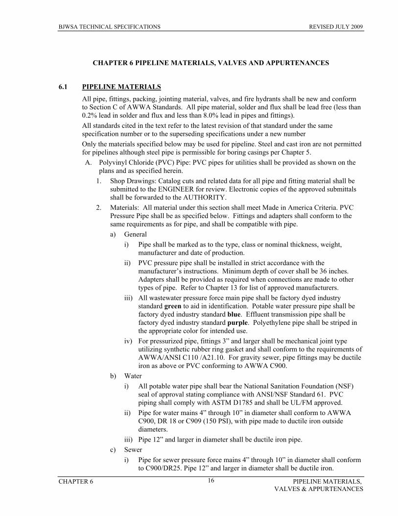
BJWSA TECHNICAL SPECIFICATIONS REVISED JULY 2009
CHAPTER 6 PIPELINE MATERIALS, VALVES & APPURTENANCES
16
CHAPTER 6 PIPELINE MATERIALS, VALVES AND APPURTENANCES
6.1 PIPELINE MATERIALS
All pipe, fittings, packing, jointing material, valves, and fire hydrants shall be new and conform to Section C of AWWA Standards. All pipe material, solder and flux shall be lead free (less than 0.2% lead in solder and flux and less than 8.0% lead in pipes and fittings). All standards cited in the text refer to the latest revision of that standard under the same specification number or to the superseding specifications under a new number Only the materials specified below may be used for pipeline. Steel and cast iron are not permitted for pipelines although steel pipe is permissible for boring casings per Chapter 5. A. Polyvinyl Chloride (PVC) Pipe: PVC pipes for utilities shall be provided as shown on the
plans and as specified herein. 1. Shop Drawings: Catalog cuts and related data for all pipe and fitting material shall be
submitted to the ENGINEER for review. Electronic copies of the approved submittals shall be forwarded to the AUTHORITY.
2. Materials: All material under this section shall meet Made in America Criteria. PVC Pressure Pipe shall be as specified below. Fittings and adapters shall conform to the same requirements as for pipe, and shall be compatible with pipe. a) General
i) Pipe shall be marked as to the type, class or nominal thickness, weight, manufacturer and date of production.
ii) PVC pressure pipe shall be installed in strict accordance with the manufacturer’s instructions. Minimum depth of cover shall be 36 inches. Adapters shall be provided as required when connections are made to other types of pipe. Refer to Chapter 13 for list of approved manufacturers.
iii) All wastewater pressure force main pipe shall be factory dyed industry standard green to aid in identification. Potable water pressure pipe shall be factory dyed industry standard blue. Effluent transmission pipe shall be factory dyed industry standard purple. Polyethylene pipe shall be striped in the appropriate color for intended use.
iv) For pressurized pipe, fittings 3” and larger shall be mechanical joint type utilizing synthetic rubber ring gasket and shall conform to the requirements of AWWA/ANSI C110 /A21.10. For gravity sewer, pipe fittings may be ductile iron as above or PVC conforming to AWWA C900.
b) Water i) All potable water pipe shall bear the National Sanitation Foundation (NSF)
seal of approval stating compliance with ANSI/NSF Standard 61. PVC piping shall comply with ASTM D1785 and shall be UL/FM approved.
ii) Pipe for water mains 4” through 10” in diameter shall conform to AWWA C900, DR 18 or C909 (150 PSI), with pipe made to ductile iron outside diameters.
iii) Pipe 12” and larger in diameter shall be ductile iron pipe. c) Sewer
i) Pipe for sewer pressure force mains 4” through 10” in diameter shall conform to C900/DR25. Pipe 12” and larger in diameter shall be ductile iron.

BJWSA TECHNICAL SPECIFICATIONS REVISED JULY 2009
CHAPTER 6 PIPELINE MATERIALS, VALVES & APPURTENANCES
17
ii) All gravity sewer pipes, 4” and larger in diameter, shall be Type PSM pipe conforming to ASTM D3034, with integral bell and spigot rubber O-ring gasket joints. SDR 26 shall be used. Gasketed fittings and accessories shall be compatible with pipe. Refer to Chapter 13 for a list of approved manufacturers.
3. Material Testing: a) Potable Water and Wastewater Pressure Forcemain Pipe: Each joint of pressure
pipe shall be subjected to and successfully meet a hydrostatic proof test at the factory in accordance with the requirements for each type. Certified test results shall be furnished to the ENGINEER for each shipment of pipe. Pipe fittings shall be subject to inspection and testing in accordance with standard manufacturing practice.
b) Gravity Sewer Pipe: PVC gravity sewer pipe, 4”and larger in diameter shall be tested by the manufacturer for pipe flattening, impact resistance, pipe stiffness, joint tightness and extrusion quality (acetone immersion) in accordance with ASTM D3034. Test certificates showing that the pipe conforms to these specifications shall be furnished to the ENGINEER for each shipment of pipe. PVC Gravity Sewer Pipe shall be installed with all pipe sections assembled in accordance with the manufacturer’s instructions to form tight joints. All pipe shall pass the deflection test as specified below.
c) Deflection Test: All PVC gravity sewer pipe 8” diameter and larger shall be tested after installation and backfill by the CONTRACTOR using methods and equipment approved in writing by the ENGINEER. Testing shall be performed at the CONTRACTOR’s expense using a 5% mandrel acceptable to the ENGINEER and BJWSA to insure that initial deflection of pipe does not exceed 5%. All deflection testing shall be performed in the presence of the ENGINEER and BJWSA. CONTRACTOR shall notify the ENGINEER and BJWSA in sufficient time to insure that the both will be present during deflection tests. Deflection testing shall not occur until roadbed sub base has been installed and compacted to its final density. Deflection test records shall identify the location and deflection amount at all points where deflection exceeds the specified limit. Such records shall be certified by the CONTRACTOR, and shall be furnished to the ENGINEER prior to acceptance and payment. Pipe with initial deflection exceeding the specified limit will be unacceptable, and shall be re-bedded to the correct deflection and retested for deflection, at the CONTRACTOR’s expense.
d) Air Test: Air testing as specified in Section 8 shall not occur until all dry utilities have been installed. Air testing shall not occur until roadbed sub base has been installed and compacted to its final density.
4. Installation: Pipe and fittings shall be installed in accordance with the requirements specified in other Chapters and the manufacturer’s instructions. Minimum depth of cover shall be 36 inches. All adapters necessary for the proper jointing of pipe and fittings shall be provided. Connections to other types of pipe shall be made as detailed on the plans. Underground fittings shall be well restrained as detailed on the plans and as specified in this section. Mark pipeline with tracer wire and marking tape. Tracer wire shall be extended from the main wire above the pipe to 12” above ground level at all valve boxes to facilitate attachment to tracing equipment.
B. Ductile Iron Pipe (DIP): Ductile iron pipe and fittings shall be provided as shown on the plans and as specified herein.
1. Shop Drawings: Catalog cuts and related data for all pipe and fitting material shall be
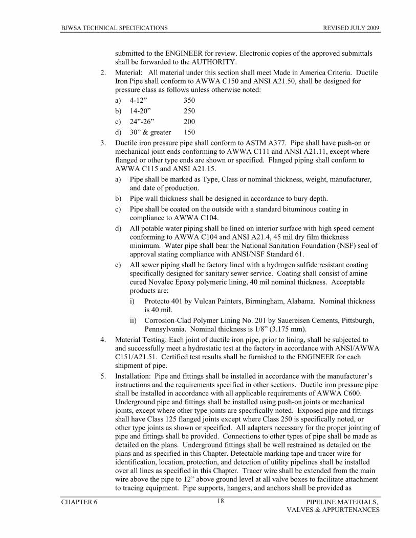
BJWSA TECHNICAL SPECIFICATIONS REVISED JULY 2009
CHAPTER 6 PIPELINE MATERIALS, VALVES & APPURTENANCES
18
submitted to the ENGINEER for review. Electronic copies of the approved submittals shall be forwarded to the AUTHORITY.
2. Material: All material under this section shall meet Made in America Criteria. Ductile Iron Pipe shall conform to AWWA C150 and ANSI A21.50, shall be designed for pressure class as follows unless otherwise noted: a) 4-12” 350 b) 14-20” 250 c) 24”-26” 200 d) 30” & greater 150
3. Ductile iron pressure pipe shall conform to ASTM A377. Pipe shall have push-on or mechanical joint ends conforming to AWWA C111 and ANSI A21.11, except where flanged or other type ends are shown or specified. Flanged piping shall conform to AWWA C115 and ANSI A21.15. a) Pipe shall be marked as Type, Class or nominal thickness, weight, manufacturer,
and date of production. b) Pipe wall thickness shall be designed in accordance to bury depth. c) Pipe shall be coated on the outside with a standard bituminous coating in
compliance to AWWA C104. d) All potable water piping shall be lined on interior surface with high speed cement
conforming to AWWA C104 and ANSI A21.4, 45 mil dry film thickness minimum. Water pipe shall bear the National Sanitation Foundation (NSF) seal of approval stating compliance with ANSI/NSF Standard 61.
e) All sewer piping shall be factory lined with a hydrogen sulfide resistant coating specifically designed for sanitary sewer service. Coating shall consist of amine cured Novalec Epoxy polymeric lining, 40 mil nominal thickness. Acceptable products are: i) Protecto 401 by Vulcan Painters, Birmingham, Alabama. Nominal thickness
is 40 mil. ii) Corrosion-Clad Polymer Lining No. 201 by Sauereisen Cements, Pittsburgh,
Pennsylvania. Nominal thickness is 1/8” (3.175 mm). 4. Material Testing: Each joint of ductile iron pipe, prior to lining, shall be subjected to
and successfully meet a hydrostatic test at the factory in accordance with ANSI/AWWA C151/A21.51. Certified test results shall be furnished to the ENGINEER for each shipment of pipe.
5. Installation: Pipe and fittings shall be installed in accordance with the manufacturer’s instructions and the requirements specified in other sections. Ductile iron pressure pipe shall be installed in accordance with all applicable requirements of AWWA C600. Underground pipe and fittings shall be installed using push-on joints or mechanical joints, except where other type joints are specifically noted. Exposed pipe and fittings shall have Class 125 flanged joints except where Class 250 is specifically noted, or other type joints as shown or specified. All adapters necessary for the proper jointing of pipe and fittings shall be provided. Connections to other types of pipe shall be made as detailed on the plans. Underground fittings shall be well restrained as detailed on the plans and as specified in this Chapter. Detectable marking tape and tracer wire for identification, location, protection, and detection of utility pipelines shall be installed over all lines as specified in this Chapter. Tracer wire shall be extended from the main wire above the pipe to 12” above ground level at all valve boxes to facilitate attachment to tracing equipment. Pipe supports, hangers, and anchors shall be provided as

BJWSA TECHNICAL SPECIFICATIONS REVISED JULY 2009
CHAPTER 6 PIPELINE MATERIALS, VALVES & APPURTENANCES
19
required. C. Polyethylene (HDPE) Pipe:
1. General: The pipe supplied under this specification shall be cast iron outside diameter (DIPS), SDR 11 high performance, high molecular weight, high density polyethylene pipe, and shall conform to ASTM D 1248 (Type III C, Category 5, P34). Minimum cell classification values shall be 345434C as referenced in ASTM D 3350. All pipe resin shall be manufactured by the same company that manufactures the pipe itself in accordance with these specifications to insure complete resin compatibility and total product accountability. The fittings supplied in this specification shall be molded or manufactured from a polyethylene compound having a cell classification equal to or exceeding the compound used in the pipe. a) All potable water pipe shall bear the National Sanitation Foundation (NSF) seal of
approval stating compliance with ANSI/NSF Standard 61. i) 1” and 2” service pipe: see Water Service, Section 7.4 ii) 4” and larger shall comply with ASTM D 3035 dimension rating. HDPE
mains may be installed along certain routes in areas where taps will not occur; such as wetland, creek, and river crossings and other non-developable areas.
b) HDPE sewer pressure force mains: i) All HDPE sewer pressure pipe shall comply with ASTM D-3035 dimension
ratings and shall be rated for 200 PSI. 2. 2” sewer pressure force mains shall consist of IPS OD High Density Polyethylene, PE
3408, SDR 7. Pipe shall be supplied on roll spool to minimize joints. Connections shall be made utilizing brass compression type couplings or heat fusion butt welds. Refer to Chapter 13 for a list of approved manufacturersShop Drawings: Catalog cuts and related data for all pipe and fitting material shall be submitted to the ENGINEER for review. Electronic copies of the approved submittals shall be forwarded to the AUTHORITY.
3. Physical Properties: Pipe shall conform to the physical properties described below: a) Typical Physical Properties:
PROPERTY TEST METHOD UNIT VALUE Density ASTM Method gms/cc 0.955 Melt Index ASTM D 1238 gms/10 min 0.14
b) Coefficient of Linear Thermal Expansion:
PROPERTY TEST METHOD UNIT VALUE Molded Specimen ASTM D 696 in./in./deg. F 8.3x10⁻⁵ Extruded Pipe 1.2x10⁻⁴ Conductivity Dynatech-Colora BTU-IN/FT/degF 2.7
c) Long Term Strength:
PROPERTY TEST METHOD UNIT VALUE 73 degrees F ASTM D 2837 PSI 1600 140 degrees F PSI 800 Material Cell Class ASTM D 3350 345434c Material Description PPI recommendation PE 3408
d) Environmental Stress Cracking Resistance:

BJWSA TECHNICAL SPECIFICATIONS REVISED JULY 2009
CHAPTER 6 PIPELINE MATERIALS, VALVES & APPURTENANCES
20
PROPERTY TEST METHOD UNIT VALUE Condition A,B,&C, F-0 ASTM D 1693 HRS >5000** Compressed Ring, F-60 Proposed ASTM HRS >800 Tensile Strength, Yield ASTM D 638 PSI 3200 Type IV Specimen (2”/min) Elongation at Break ASTM D 638 % >750 Vicate Softening Temp ASTM D 1525 deg F 257 Brittleness Temp ASTM D 746 deg F <-180 Flexural Modulus ASTM D 3350 PSI 125,000 Modulus of Elasticity ASTM D 638 PSI 105,000 Hardness ASTM D 2240 Shore D 64
4. Quality Control: The resin used for manufacturer of the pipe shall be manufactured by
the pipe manufacturer, thus maintaining complete quality control of the pipe. The pipe shall contain no recycled compound except that generated in the manufacturer’s own plant from resin of the same specification from the same raw material. The pipe shall be homogenous throughout and free of visible cracks, holes, foreign inclusions, or other deleterious defects and shall be identical in color, density, melt index, and other physical properties. The polyethylene resin used shall have all ingredients pre-compound prior to extrusion of pipe, in plant blending is not acceptable. BJWSA may request, as part of the quality control records submittal, certification that the pipe produced is represented by the quality assurance testing. Additionally, test results from manufacturer’s testing or random sampling by the ENGINEER that do not meet appropriate ASTM standards or manufacturer’s representation, may be cause for rejection of pipe represented by the testing. These tests may include density and flow rate measurements from samples taken at selected locations within the pipe wall and thermal stability determinations according to ASTM D. a) BJWSA may request certified lab data to verify the physical properties of the
materials supplied under this specification or may take random samples and have them tested by an independent laboratory.
b) Pipe Marking: All piping shall marked for identification with a minimum of four (4) longitudinal stripes of color corresponding to use.
c) Rejection: BJWSA reserves the right to reject any polyethylene pipe and fittings failing to meet any of the requirements of this specification.
d) Pipe Dimensions: Pipe supplied under this specification shall have a nominal cast iron outside diameter unless otherwise specified. The SDR (Standard Dimension Ratio) of the pipe supplied shall be as specified by BJWSA.
5. Construction Practices: a) Handling of Pipe: Pipe shall be stored on clean, level ground to prevent undue
scratching or gouging of the pipe. If the pipe must be stacked for storage, such stacking should be done in accordance with the pipe manufacturer’s recommendations. The handling of the pipe should be done in such a manner that it is damaged by dragging over sharp objects or cut by chokers or lifting equipment.
b) Repair of Damaged Sections: Segments of pipe having cuts or gouges in excess of 10% of the wall thickness of the pipe should be cut and removed. The undamaged portions of the pipe shall be rejoined using the butt fusion joining method in this Chapter.
c) Pipe Joining: Sections of polyethylene pipe should be joined into continuous
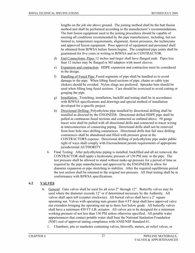
BJWSA TECHNICAL SPECIFICATIONS REVISED JULY 2009
CHAPTER 6 PIPELINE MATERIALS, VALVES & APPURTENANCES
21
lengths on the job site above ground. The joining method shall be the butt fusion method and shall be performed according to the manufacturer’s recommendations. The butt fusion equipment used in the joining procedures should be capable of meeting all conditions recommended by the pipe manufacturer, including, but not limited to, temperature requirements, alignment, fusion pressures, the technicians and approved fusion equipment. Prior approval of equipment and personnel shall be obtained from BJWSA before fusion begins. The completed pipe joints shall be guaranteed for five years in writing to BJWSA and its CONTRACTOR.
d) End Connections: Pipes 12 inches and larger shall have flanged ends. Pipes less than 12 inches may be flanged or MJ adapters with insert sleeves.
e) Expansion and contraction: HDPE expansion and contraction must be considered in the design.
f) Handling of Fused Pipe: Fused segments of pipe shall be handled so to avoid damage to the pipe. When lifting fused sections of pipe, chains or cable type chokers should be avoided. Nylon slings are preferred. Spreader bars should be used when lifting long fused sections. Care should be exercised to avoid cutting or gouging the pipe.
g) Installation: Trenching, installation, backfill and testing shall be in accordance with BJWSA specifications and drawings and special method of installation developed for a specific project.
h) Directional Drilling: Polyethylene pipe installed by directional drilling shall be installed as directed by the ENGINEER. Directional drilled HDPE pipe shall be pulled in continuous fused sections and connected as outlined above. #8 gauge tracer wire shall be pulled with all directional drills and connected to tracer wiring at interconnection of connecting piping. Directional drills shall not be removed from bore hole once drilling commences. Directional drills that fail once drilling commences shall be abandoned and filled with pressure grout at the CONTRACTORS expense. Directional drilling of polyethylene pipe under public right of ways shall comply with Encroachment permit requirements of appropriate jurisdictional AUTHORITY.
6. Final Testing: After polyethylene piping is installed, backfilled and all air removed, the CONTRACTOR shall apply a hydrostatic pressure of 150 PSI min. to the pipe. The test pressure shall be allowed to stand without make-up pressure for a period of time as required by the pipe manufacturer and approved by the ENGINEER to allow for diameter expansion or pipe stretching to stabilize. After the required equilibrium period the test section shall be returned to the original test pressure. All final testing shall be in conformance with BJWSA specifications.
6.2 VALVES
A. General: Gate valves shall be used for all sizes 2” through 12”. Butterfly valves may be used where the diameter exceeds 12” or if determined necessary by the Authority. All valves shall open left (counter clockwise). All buried valves shall have a 2” square operating nut. Valves with operating nuts greater than 4 FT deep shall have approved valve nut extenders bringing the operating nut up to three feet below grade. All butterfly valves shall have a minimum 450 FT-LB. actuator. All valves are to be designed for a minimum working pressure of not less than 150 PSI unless otherwise specified. All potable water appurtenances that contact potable water shall bear the National Sanitation Foundation (NSF) seal of approval stating compliance with ANSI/NSF Standard 61.
1. Chambers, pits or manholes containing valves, blowoffs, meters, air relief valves, or

BJWSA TECHNICAL SPECIFICATIONS REVISED JULY 2009
CHAPTER 6 PIPELINE MATERIALS, VALVES & APPURTENANCES
22
other such appurtenances to a distribution system, shall not be connected directly to any storm drain or sanitary sewer.
2. Shop Drawings: Catalog cuts and related data for all valves and fitting material shall be submitted to the ENGINEER for review. Electronic copies of the approved submittals shall be forwarded to the AUTHORITY.
B. Gate Valves: All resilient wedge gate valves shall comply with all requirements of AWWA C509, latest revision, and with the below listed requirements. Valves shall be designed for 250 PSI working pressure, factory seat tested at 250 PSI with no leakage past the seat from either side of the disc, and shell tested at 500 PSI. Minimum body and bonnet wall thickness shall be as set forth in Table 2, Section 4.3.1 of AWWA C509. Body and bonnet wall thickness less than the minimum thickness shall not be acceptable. Bonnet to body seal shall be effected by a flat neoprene gasket. Bonnet and body flanges shall be fully machined to assure proper sealing of the gasket. Valve body interior and exterior shall be coated with a minimum of 10 mil of fusion bond epoxy or nylon coating. End connections shall be flanged in accordance with Class 125, ANSI B16.1 for above ground installation, and mechanical joint for underground installation in accordance with AWWA C110/111 or slip-on for use with cast iron OD pipe. Valves shall be of the non-rising stem (N.R.S.) design and shall open left (counter-clockwise). Valves installed above ground and in underground vaults, where specified, shall be furnished with gear actuated hand wheels. All buried valves shall be furnished with 2” square operating nuts. Maximum bury depth to nut shall be 4 FT or valve nut extensions shall be provided. Valves shall have O-Ring sealed stems with one O-Ring located below the thrust collar and with two O-Rings located above the thrust collar. The thrust collar area between the two lower O-Rings shall be factory filled with a lubricant to provide permanent lubrication of the thrust collar area. Valve stems shall be of bronze rolled bar stock and shall have a forged thrust collar. The stem material shall provide 70,000 PSI tensile strength with 15% elongation and a yield strength of 30,000 PSI. Cast stems shall not be acceptable. Stems shall have acme form threads for strength and efficiency. An anti-friction thrust washer shall be provided both above and below the thrust collar for ease of operation. The resilient-seated disc wedge shall be of the resilient wedge fully supported type. Solid guide lugs shall travel within channels in the body of the valve. The disc and guide lugs shall be fully (100%) encapsulated in EPDM rubber. All appurtenances that contact potable water shall bear the National Sanitation Foundation (NSF) seal of approval stating compliance with ANSI/NSF Standard 61. Refer to Chapter 13 for a list of approved manufacturers.
C. Butterfly Valves: All butterfly valves, except as herein otherwise noted, shall conform to AWWA C504, latest revision. Valve body interior and exterior shall be coated with a minimum of 10 mil of fusion bond epoxy or nylon coating. All valve shafts shall be connected to operators by the use of keys and keyways. The use of compression or friction connections is not acceptable. The seat on disc valves shall be continuous around the periphery of the disc and shall not be penetrated by the valve shaft. Buried service butterfly valves shall be integrally cast mechanical joint ends, short body type, AWWA Class 150B with totally enclosed geared operator and a 2” square operating nut. Valves shall have ASTM A 126, Class 40 cast iron valve body with 125 PSI full faced flanges drilled in accordance with ANSI B16.1. Valve disc shall be contoured cast iron or ductile iron. Standard service above ground butterfly valves shall be flanged end, short body type with enclosed gear actuated hand wheel operators. Valve shaft shall be Type 304 stainless steel with self-lubricating, corrosion resistant sleeve type bearings. Operators shall be 450 FT-LB. gear actuators and be fully gasketed and grease packed to withstand an external ground water pressure of 10 PSI minimum. A valve position indicator shall be furnished for installation in each valve box. The indicator shall be hermetically sealed for installation inside a cast iron valve box and shall show valve disc position, direction of rotation, and

BJWSA TECHNICAL SPECIFICATIONS REVISED JULY 2009
CHAPTER 6 PIPELINE MATERIALS, VALVES & APPURTENANCES
23
number of turns from fully opened to fully closed. This indicator shall be provided by the valve manufacturer, complete. Appurtenances that contact potable water shall bear the National Sanitation Foundation (NSF) seal of approval stating compliance with ANSI/NSF Standard 61. Refer to Chapter 13 for a list of approved manufacturers.
D. Plug Valves: Plug valves shall be used on all sewer applications unless approved otherwise by the AUTHORITY. Valves shall be used for installations above ground, direct bury, in concrete vaults or for installations in manholes. Valves installed above ground, in concrete vaults or installed in manholes shall be provided with hand wheel actuators. Valves 4” and larger shall have a minimum 450 FT-LB gear driven actuator and shall be capable of opening valve at rated pressure of 150 PSI. All direct buried sewer pressure force main valves shall have gear actuators with a 2” square operating nut located at a depth not to exceed 4 FT in valve box and concrete collar. Valves on sewer pressure force mains shall be installed at maximum intervals of 2000 FT or as directed by the AUTHORITY. Valves shall open left (counter clockwise). Valves are to be designed for a minimum working pressure of not less than 150 PSI. Valves shall be the non-lubricated eccentric plug type with a resilient seat seal unless otherwise specified and shall be furnished with mechanical joint ends in accordance with ANSI Standard A21.11, unless specified otherwise on the plans. Port area for valves shall be a minimum of 80% of the full pipe area. Valve bodies shall be of ASTM A-126 Class B cast iron. Resilient seat seals shall be of Buna-N or Neoprene, suitable for use in sewage service. Seats shall be of non-metallic with seat coating thermally bonded and in full conformance to AWWA Standard C550. Valves shall be furnished with permanent corrosion resistant bearing surfaces in the upper and lower journals designated to withstand full rated bearing loads and provide long life in sewage service. Valves shall have their internal and external surface protected by fusion bond epoxy or nylon coatings factory applied, thermally bonded and in full conformance to AWWA Standard C550. Nominal valve pressure ratings, body flanges and wall thickness shall be in full conformance to ANSI B16.1-1975. Valves shall seal leak-tight against full rated pressure in both directions. Valve seats shall be tested and provide leak-tight shut-off to 175 PSI for valves 14” and larger, with pressure in each direction. A hydrostatic shell test at twice the rating shall be performed with plug open to demonstrate overall pressure envelope integrity. All gearing shall be fully enclosed in a suitable housing and be suitable for running in a lubricant with seals provided on all shafts to prevent entry of dirt and water into the actuator. A suitable stop shall be set to provide watertight shut off in the closed position at full rated pressure. Valve actuators for buried or submerged service shall have seals on all shafts and gaskets on the valve and actuator covers to prevent the entry of water. Actuator mounting brackets for buried or submerged service shall be totally enclosed and shall have gasket or o-ring seals. All exposed nuts, bolts, springs, and washer used in buried service shall be type 316 stainless steel. Refer to Chapter 13 for list of approved manufacturers.
E. Swing Check Valves (above ground or in vault): The CONTRACTOR will furnish and install swing check valves as shown on the plans and in accordance with these specifications. Swing check valves shall comply with all requirements of AWWA C508, latest revision, and with the requirements listed below.
1. Valve body interior and exterior shall be coated with a minimum of 10 mil of fusion bond epoxy or nylon coating.
2. All potable water appurtenances that contact potable water shall bear the National Sanitation Foundation (NSF) seal of approval stating compliance with ANSI/NSF Standard 61.
3. For swing check valves 4” and larger, bodies and bonnets will consist of ductile iron and will be designed to allow removal of the clapper arm and disc assembly through the
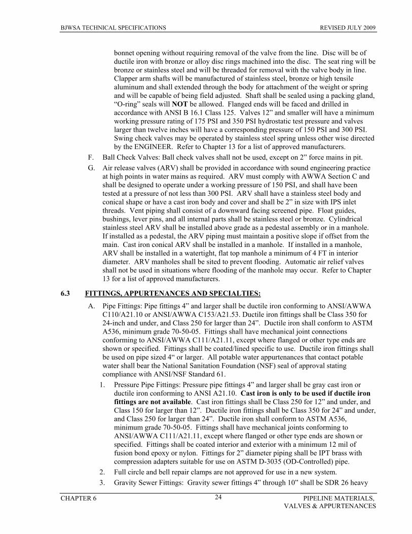
BJWSA TECHNICAL SPECIFICATIONS REVISED JULY 2009
CHAPTER 6 PIPELINE MATERIALS, VALVES & APPURTENANCES
24
bonnet opening without requiring removal of the valve from the line. Disc will be of ductile iron with bronze or alloy disc rings machined into the disc. The seat ring will be bronze or stainless steel and will be threaded for removal with the valve body in line. Clapper arm shafts will be manufactured of stainless steel, bronze or high tensile aluminum and shall extended through the body for attachment of the weight or spring and will be capable of being field adjusted. Shaft shall be sealed using a packing gland, “O-ring” seals will NOT be allowed. Flanged ends will be faced and drilled in accordance with ANSI B 16.1 Class 125. Valves 12” and smaller will have a minimum working pressure rating of 175 PSI and 350 PSI hydrostatic test pressure and valves larger than twelve inches will have a corresponding pressure of 150 PSI and 300 PSI. Swing check valves may be operated by stainless steel spring unless other wise directed by the ENGINEER. Refer to Chapter 13 for a list of approved manufacturers.
F. Ball Check Valves: Ball check valves shall not be used, except on 2” force mains in pit. G. Air release valves (ARV) shall be provided in accordance with sound engineering practice
at high points in water mains as required. ARV must comply with AWWA Section C and shall be designed to operate under a working pressure of 150 PSI, and shall have been tested at a pressure of not less than 300 PSI. ARV shall have a stainless steel body and conical shape or have a cast iron body and cover and shall be 2” in size with IPS inlet threads. Vent piping shall consist of a downward facing screened pipe. Float guides, bushings, lever pins, and all internal parts shall be stainless steel or bronze. Cylindrical stainless steel ARV shall be installed above grade as a pedestal assembly or in a manhole. If installed as a pedestal, the ARV piping must maintain a positive slope if offset from the main. Cast iron conical ARV shall be installed in a manhole. If installed in a manhole, ARV shall be installed in a watertight, flat top manhole a minimum of 4 FT in interior diameter. ARV manholes shall be sited to prevent flooding. Automatic air relief valves shall not be used in situations where flooding of the manhole may occur. Refer to Chapter 13 for a list of approved manufacturers.
6.3 FITTINGS, APPURTENANCES AND SPECIALTIES:
A. Pipe Fittings: Pipe fittings 4” and larger shall be ductile iron conforming to ANSI/AWWA C110/A21.10 or ANSI/AWWA C153/A21.53. Ductile iron fittings shall be Class 350 for 24-inch and under, and Class 250 for larger than 24”. Ductile iron shall conform to ASTM A536, minimum grade 70-50-05. Fittings shall have mechanical joint connections conforming to ANSI/AWWA C111/A21.11, except where flanged or other type ends are shown or specified. Fittings shall be coated/lined specific to use. Ductile iron fittings shall be used on pipe sized 4“ or larger. All potable water appurtenances that contact potable water shall bear the National Sanitation Foundation (NSF) seal of approval stating compliance with ANSI/NSF Standard 61.
1. Pressure Pipe Fittings: Pressure pipe fittings 4” and larger shall be gray cast iron or ductile iron conforming to ANSI A21.10. Cast iron is only to be used if ductile iron fittings are not available. Cast iron fittings shall be Class 250 for 12” and under, and Class 150 for larger than 12”. Ductile iron fittings shall be Class 350 for 24” and under, and Class 250 for larger than 24”. Ductile iron shall conform to ASTM A536, minimum grade 70-50-05. Fittings shall have mechanical joints conforming to ANSI/AWWA C111/A21.11, except where flanged or other type ends are shown or specified. Fittings shall be coated interior and exterior with a minimum 12 mil of fusion bond epoxy or nylon. Fittings for 2” diameter piping shall be IPT brass with compression adapters suitable for use on ASTM D-3035 (OD-Controlled) pipe.
2. Full circle and bell repair clamps are not approved for use in a new system. 3. Gravity Sewer Fittings: Gravity sewer fittings 4” through 10” shall be SDR 26 heavy
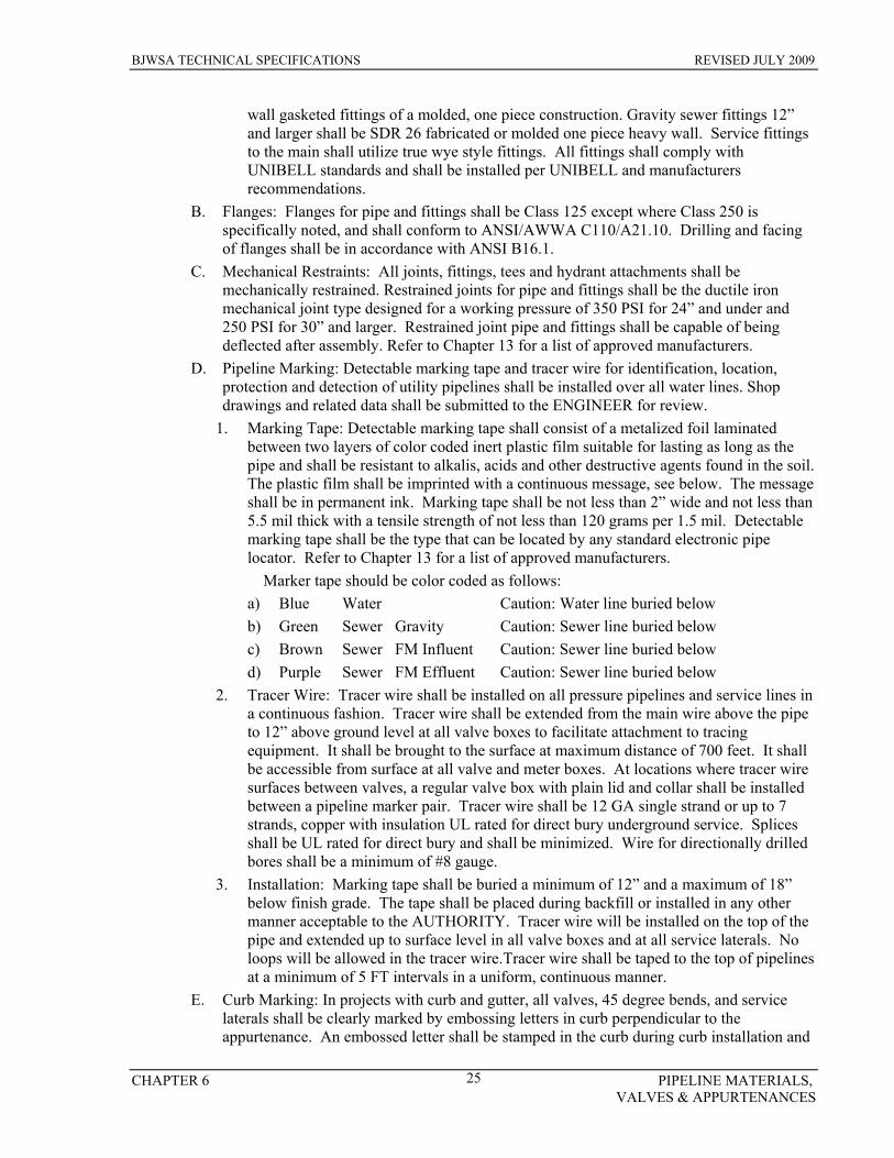
BJWSA TECHNICAL SPECIFICATIONS REVISED JULY 2009
CHAPTER 6 PIPELINE MATERIALS, VALVES & APPURTENANCES
25
wall gasketed fittings of a molded, one piece construction. Gravity sewer fittings 12” and larger shall be SDR 26 fabricated or molded one piece heavy wall. Service fittings to the main shall utilize true wye style fittings. All fittings shall comply with UNIBELL standards and shall be installed per UNIBELL and manufacturers recommendations.
B. Flanges: Flanges for pipe and fittings shall be Class 125 except where Class 250 is specifically noted, and shall conform to ANSI/AWWA C110/A21.10. Drilling and facing of flanges shall be in accordance with ANSI B16.1.
C. Mechanical Restraints: All joints, fittings, tees and hydrant attachments shall be mechanically restrained. Restrained joints for pipe and fittings shall be the ductile iron mechanical joint type designed for a working pressure of 350 PSI for 24” and under and 250 PSI for 30” and larger. Restrained joint pipe and fittings shall be capable of being deflected after assembly. Refer to Chapter 13 for a list of approved manufacturers.
D. Pipeline Marking: Detectable marking tape and tracer wire for identification, location, protection and detection of utility pipelines shall be installed over all water lines. Shop drawings and related data shall be submitted to the ENGINEER for review.
1. Marking Tape: Detectable marking tape shall consist of a metalized foil laminated between two layers of color coded inert plastic film suitable for lasting as long as the pipe and shall be resistant to alkalis, acids and other destructive agents found in the soil. The plastic film shall be imprinted with a continuous message, see below. The message shall be in permanent ink. Marking tape shall be not less than 2” wide and not less than 5.5 mil thick with a tensile strength of not less than 120 grams per 1.5 mil. Detectable marking tape shall be the type that can be located by any standard electronic pipe locator. Refer to Chapter 13 for a list of approved manufacturers.
Marker tape should be color coded as follows: a) Blue Water Caution: Water line buried below b) Green Sewer Gravity Caution: Sewer line buried below c) Brown Sewer FM Influent Caution: Sewer line buried below d) Purple Sewer FM Effluent Caution: Sewer line buried below
2. Tracer Wire: Tracer wire shall be installed on all pressure pipelines and service lines in a continuous fashion. Tracer wire shall be extended from the main wire above the pipe to 12” above ground level at all valve boxes to facilitate attachment to tracing equipment. It shall be brought to the surface at maximum distance of 700 feet. It shall be accessible from surface at all valve and meter boxes. At locations where tracer wire surfaces between valves, a regular valve box with plain lid and collar shall be installed between a pipeline marker pair. Tracer wire shall be 12 GA single strand or up to 7 strands, copper with insulation UL rated for direct bury underground service. Splices shall be UL rated for direct bury and shall be minimized. Wire for directionally drilled bores shall be a minimum of #8 gauge.
3. Installation: Marking tape shall be buried a minimum of 12” and a maximum of 18” below finish grade. The tape shall be placed during backfill or installed in any other manner acceptable to the AUTHORITY. Tracer wire will be installed on the top of the pipe and extended up to surface level in all valve boxes and at all service laterals. No loops will be allowed in the tracer wire.Tracer wire shall be taped to the top of pipelines at a minimum of 5 FT intervals in a uniform, continuous manner.
E. Curb Marking: In projects with curb and gutter, all valves, 45 degree bends, and service laterals shall be clearly marked by embossing letters in curb perpendicular to the appurtenance. An embossed letter shall be stamped in the curb during curb installation and

BJWSA TECHNICAL SPECIFICATIONS REVISED JULY 2009
CHAPTER 6 PIPELINE MATERIALS, VALVES & APPURTENANCES
26
shall consist of a minimum 3” tall. Lettering shall be “S” for sewer services, “V” for valves, “ B” for bend in main, and “W” for water services. Curb marking is in addition to valve and pipe line markers unless 2” diameter brass surveyor’s disks are imbedded beside letter with appropriate stamped details.
F. Tapping Sleeves: Size on size pipeline taps are NOT approved for installations in the BJWSA system. Tapping sleeves shall be fabricated stainless steel with stainless steel bolts. Tapping sleeves shall have outlet flange counter bored to accept a mating tapping valve per MSS SP-60 for true alignment of tapping valve and tapping machine. Sleeve shall have a stepped stainless steel valve flange complying with AWWA C207 Class D, ANSI 316.5, 150 LB drilling. Refer to Chapter 13 for a list of approved manufacturers.
G. Miscellaneous Appurtenances and Specialties: All material and products under this section must comply with AWWA Section C and shall meet Made in America Criteria. Miscellaneous piping appurtenances and specialties shall be provided where shown on the plans and as required for a complete installation. All appurtenances that contact potable water shall bear the National Sanitation Foundation (NSF) seal of approval for compliance with ANSI/NSF Standard 61.
1. Mechanical Couplings and Adapters: Mechanical couplings and adapters shall be the type and size as shown on the plans, complete with rings, followers, gaskets, bolts, nuts and other items necessary for a complete installation. Couplings and adapters shall be installed in accordance with the manufacturer’s instructions to provide permanently tight joints under all reasonable conditions of expansion, contraction, shifting and settlement.
2. Gaskets: Gaskets for water pipe and fittings shall be vulcanized synthetic rubber free of porous areas, foreign material and visible defects. Gaskets shall be designed to provide a permanent watertight seal at all joints. Rubber gaskets shall conform to all applicable provisions of ASTM F477 and must comply with AWWA Section C. Gasket lubricant shall be non-toxic, shall not support growth of bacteria, shall not impart taste or odor to water, must be NSF certified, and shall have no deteriorating effects on gaskets. Lubricant shall be suitable for the intended use, and shall remain in a usable stage throughout the range of temperature in which the pipe is normally installed. Lubricant shall be delivered to the job site in unopened containers bearing the manufacturer’s name and trade name or trademark. Lubricant shall not be vegetable shortening.
3. Pre-cast Utility Boxes: Pre-cast utility boxes or vaults shall be provided where noted on the plans. Pre-cast concrete shall have a minimum compressive strength of 4000 PSI. Unless otherwise indicated, boxes and vaults shall be provided with traffic type aluminum frames and covers, hinged access doors, and cast iron or composite plastic-steel steps. Pre-cast boxes or vaults shall be installed level and plumb with pipe openings at the proper elevation. Joint sealant shall be rubber, cement, or other type standard with the manufacturer. All pre-cast boxes and vaults shall be designed for heavy traffic loading in accordance with ASTM C857. Pre-cast boxes or vaults used as liquid retaining structures shall be tested for leakage; all leaks shall be repaired prior to final acceptance. All boxes shall contain pump out sump and be sloped to sump.
4. Utility Manholes: Utility manholes for valves and other equipment shall be constructed of pre-cast or cast-in-place concrete. Unless otherwise indicated, manholes shall be provided with a traffic type aluminum frame and cover and cast iron or composite plastic-steel steps. Joint sealant in pre-cast manholes shall be rubber, cement, or other type standard with the manufacturer. Where noted, valves and other equipment shall be installed in a concrete pipe vault with cast iron manhole frame and cover. Manhole tops shall be set flush with grade or pavement, unless otherwise directed.
5. Valve Extensions: Valve nut extensions shall have the following properties:
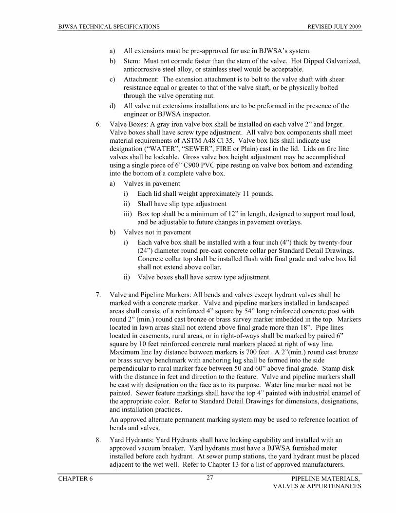
BJWSA TECHNICAL SPECIFICATIONS REVISED JULY 2009
CHAPTER 6 PIPELINE MATERIALS, VALVES & APPURTENANCES
27
a) All extensions must be pre-approved for use in BJWSA’s system. b) Stem: Must not corrode faster than the stem of the valve. Hot Dipped Galvanized,
anticorrosive steel alloy, or stainless steel would be acceptable. c) Attachment: The extension attachment is to bolt to the valve shaft with shear
resistance equal or greater to that of the valve shaft, or be physically bolted through the valve operating nut.
d) All valve nut extensions installations are to be preformed in the presence of the engineer or BJWSA inspector.
6. Valve Boxes: A gray iron valve box shall be installed on each valve 2” and larger. Valve boxes shall have screw type adjustment. All valve box components shall meet material requirements of ASTM A48 Cl 35. Valve box lids shall indicate use designation (“WATER”, “SEWER”, FIRE or Plain) cast in the lid. Lids on fire line valves shall be lockable. Gross valve box height adjustment may be accomplished using a single piece of 6” C900 PVC pipe resting on valve box bottom and extending into the bottom of a complete valve box. a) Valves in pavement
i) Each lid shall weight approximately 11 pounds. ii) Shall have slip type adjustment iii) Box top shall be a minimum of 12” in length, designed to support road load,
and be adjustable to future changes in pavement overlays. b) Valves not in pavement
i) Each valve box shall be installed with a four inch (4”) thick by twenty-four (24”) diameter round pre-cast concrete collar per Standard Detail Drawings. Concrete collar top shall be installed flush with final grade and valve box lid shall not extend above collar.
ii) Valve boxes shall have screw type adjustment.
7. Valve and Pipeline Markers: All bends and valves except hydrant valves shall be marked with a concrete marker. Valve and pipeline markers installed in landscaped areas shall consist of a reinforced 4” square by 54” long reinforced concrete post with round 2” (min.) round cast bronze or brass survey marker imbedded in the top. Markers located in lawn areas shall not extend above final grade more than 18”. Pipe lines located in easements, rural areas, or in right-of-ways shall be marked by paired 6” square by 10 feet reinforced concrete rural markers placed at right of way line. Maximum line lay distance between markers is 700 feet. A 2”(min.) round cast bronze or brass survey benchmark with anchoring lug shall be formed into the side perpendicular to rural marker face between 50 and 60” above final grade. Stamp disk with the distance in feet and direction to the feature. Valve and pipeline markers shall be cast with designation on the face as to its purpose. Water line marker need not be painted. Sewer feature markings shall have the top 4” painted with industrial enamel of the appropriate color. Refer to Standard Detail Drawings for dimensions, designations, and installation practices. An approved alternate permanent marking system may be used to reference location of bends and valves.
8. Yard Hydrants: Yard Hydrants shall have locking capability and installed with an approved vacuum breaker. Yard hydrants must have a BJWSA furnished meter installed before each hydrant. At sewer pump stations, the yard hydrant must be placed adjacent to the wet well. Refer to Chapter 13 for a list of approved manufacturers.
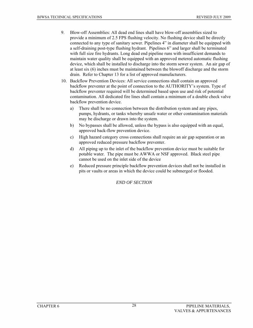
BJWSA TECHNICAL SPECIFICATIONS REVISED JULY 2009
CHAPTER 6 PIPELINE MATERIALS, VALVES & APPURTENANCES
28
9. Blow-off Assemblies: All dead end lines shall have blow-off assemblies sized to provide a minimum of 2.5 FPS flushing velocity. No flushing device shall be directly connected to any type of sanitary sewer. Pipelines 4” in diameter shall be equipped with a self-draining post-type flushing hydrant. Pipelines 6” and larger shall be terminated with full size fire hydrants. Long dead end pipeline runs with insufficient demands to maintain water quality shall be equipped with an approved metered automatic flushing device, which shall be installed to discharge into the storm sewer system. An air gap of at least six (6) inches must be maintained between the blowoff discharge and the storm drain. Refer to Chapter 13 for a list of approved manufacturers.
10. Backflow Prevention Devices: All service connections shall contain an approved backflow preventer at the point of connection to the AUTHORITY’s system. Type of backflow preventer required will be determined based upon use and risk of potential contamination. All dedicated fire lines shall contain a minimum of a double check valve backflow prevention device. a) There shall be no connection between the distribution system and any pipes,
pumps, hydrants, or tanks whereby unsafe water or other contamination materials may be discharge or drawn into the system.
b) No bypasses shall be allowed, unless the bypass is also equipped with an equal, approved back-flow prevention device.
c) High hazard category cross connections shall require an air gap separation or an approved reduced pressure backflow preventer.
d) All piping up to the inlet of the backflow prevention device must be suitable for potable water. The pipe must be AWWA or NSF approved. Black steel pipe cannot be used on the inlet side of the device
e) Reduced pressure principle backflow prevention devices shall not be installed in pits or vaults or areas in which the device could be submerged or flooded.
END OF SECTION

BJWSA TECHNICAL SPECIFICATIONS REVISED JULY 2009
CHAPTER 7 WATER SYSTEM STANDARDS 29
CHAPTER 7 WATER SYSTEM STANDARDS
7.1 SCOPE
Water pipelines and appurtenances shall be provided as shown on the plans and as specified herein. Clearing, grubbing, trench excavation and backfill, pipe material, fire hydrants, valves, cutting and replacing pavement, and removing and replacing sidewalk shall be as specified in other chapters. All applicable provisions shall be binding upon work covered in this section.
7.2 WATER SYSTEM DESIGN GUIDELINES:
These guidelines are based on Federal, State, and local health requirements and BJWSA design criteria. Design Criteria not indicated herein shall comply with “Ten State Standards” where applicable. All installations shall meet quality standards of the South Carolina Department of Health and Environmental Control (SCDHEC). A. Water System Design Criteria:
1. Distribution Main Size: Minimum 4” diameter unless otherwise approved by the AUTHORITY. Water mains providing fire service shall be a minimum of 6” diameter.
2. Sizing of Lines: For pipelines 6” and larger, sizes shall be based on either 1/5th the instantaneous maximum flow plus the fire flow or maximum instantaneous demand, which ever is greater. The minimum design fire flow in the BJWSA system shall be 1,000 GPM with a minimum residual pressure of 20 PSI. For pipe sizes 4” and smaller, sizes shall be based on either 1/5th the instantaneous maximum flow plus the blow off flow or maximum instantaneous demand, which ever is greater.
3. Valves: Provide three (3) valves for a tee intersection, four (4) valves for a cross intersection. Sufficient valves shall be provided on water mains so that public inconvenience and sanitary hazards will be minimized during repairs. Valves should be located at not more than 500 FT intervals in commercial areas and at not more than one block or 800 FT intervals in residential areas. Valves on transmission mains and rural distribution mains shall be installed in intervals no greater than 2000 ft. Valves should be placed to minimize the number of BJWSA customers out of service due to a main break or any other maintenance operation. The AUTHORITY reserves the right to require additional valves if it is deemed in the best interest of current and future BJWSA customers.
4. Dead ends: Dead ends shall be minimized by designing mains so they are looped and interconnected at intersections. The AUTHORITY reserves the right to reject any dead end pipeline greater than 4” diameter if the possibility exists for stagnation of water due to non-use. The maximum length of 4” water pipelines shall be 1000 FT.
B. Water Pipeline Considerations: All materials and products shall meet Made in America Criteria. Materials not meeting this requirement shall only be acceptable with prior written approval from the AUTHORITY. Natural rubber or other materials, which are capable of supporting microbiological growth, may not be used in any appurtenance in direct contact with potable water. Water mains shall be located out of contaminated areas, unless using pipe materials that will protect (i.e. DIP with chemical resistant gaskets.) Reroute line if possible.
C. Waterlines 4” through 10” may be DIP or PVC. All fittings shall be DIP. Pipe Sizes of 1-1/4”, 1-1/2”, 2-1/2”, and 3” are not approved for installation in BJWSA systems. 1” and 2” pipe shall only be approved for service taps. Asbestos cement, concrete and steel piping is not allowed. Refer to Chapter 6: Pipeline Materials and Appurtenances for relevant
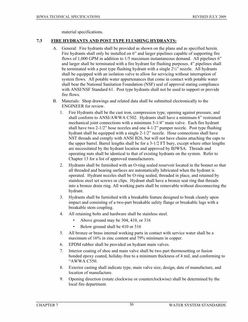
BJWSA TECHNICAL SPECIFICATIONS REVISED JULY 2009
CHAPTER 7 WATER SYSTEM STANDARDS 30
material specifications.
7.3 FIRE HYDRANTS AND POST TYPE FLUSHING HYDRANTS:
A. General: Fire hydrants shall be provided as shown on the plans and as specified herein. Fire hydrants shall only be installed on 6” and larger pipelines capable of supporting fire flows of 1,000 GPM in addition to 1/5 maximum instantaneous demand. All pipelines 6” and larger shall be terminated with a fire hydrant for flushing purposes. 4” pipelines shall be terminated with a post type flushing hydrant with a single 2½” nozzle. All hydrants shall be equipped with an isolation valve to allow for servicing without interruption of system flows. All potable water appurtenances that come in contact with potable water shall bear the National Sanitation Foundation (NSF) seal of approval stating compliance with ANSI/NSF Standard 61. Post type hydrants shall not be used to support or provide fire flows.
B. Materials: Shop drawings and related data shall be submitted electronically to the ENGINEER for review.
1. Fire Hydrants shall be the cast iron, compression type, opening against pressure, and shall conform to ANSI/AWWA C502. Hydrants shall have a minimum 6” restrained mechanical joint connections with a minimum 5-1/4” main valve. Each fire hydrant shall have two 2-1/2” hose nozzles and one 4-1/2” pumper nozzle. Post type flushing hydrant shall be equipped with a single 2-1/2” nozzle. Hose connections shall have NST threads and comply with ANSI B26, but will not have chains attaching the caps to the upper barrel. Barrel lengths shall be for a 3-1/2 FT bury, except where other lengths are necessitated by the hydrant location and approved by BJWSA. Threads and operating nuts shall be identical to that of existing hydrants on the system. Refer to Chapter 13 for a list of approved manufacturers.
2. Hydrants shall be furnished with an O-ring sealed reservoir located in the bonnet so that all threaded and bearing surfaces are automatically lubricated when the hydrant is operated. Hydrant nozzles shall be O-ring sealed, threaded in place, and retained by stainless steel set screws or clips. Hydrant shall have a bronze seat ring that threads into a bronze drain ring. All working parts shall be removable without disconnecting the hydrant.
3. Hydrants shall be furnished with a breakable feature designed to break cleanly upon impact and consisting of a two-part breakable safety flange or breakable lugs with a breakable stem coupling.
4. All retaining bolts and hardware shall be stainless steel. • Above ground may be 304, 410, or 316 • Below ground shall be 410 or 316
5. All bronze or brass internal working parts in contact with service water shall be a maximum of 16% in zinc content and 79% minimum in copper.
6. EPDM rubber shall be provided on hydrant main valves. 7. Interior coating of shoe and main valve shall be two part thermosetting or fusion
bonded epoxy coated, holiday-free to a minimum thickness of 4 mil, and conforming to “AWWA C550.
8. Exterior casting shall indicate type, main valve size, design, date of manufacture, and location of manufacture.
9. Opening direction (rotate clockwise or counterclockwise) shall be determined by the local fire department.
BJWSA TECHNICAL SPECIFICATIONS REVISED JULY 2009
CHAPTER 7 WATER SYSTEM STANDARDS 31
10. Exterior coating shall be factory coated and based on the opening direction as determined by the local fire department. a) Hydrants which open counterclockwise or left shall be painted silver (Sherwin-
Williams – Silver Bright Code – B596511) with red (Sherwin-Williams – Steel Master line #9500 Code – B56R300) bonnet and nozzle caps. Generally, such hydrants are located in the City of Beaufort, Town of Port Royal, Military Bases, and Town of Hardeeville areas.
b) Hydrants which open clockwise or right shall be painted Safety Yellow (Sherwin-Williams—Steel Master line #9500 Code- Safety Yellow B56Y300). Generally, these hydrants are located in areas outside the City of Beaufort, Town of Port Royal, Military Bases, and Town of Hardeeville.
c) Developer may choose a different fire hydrant color if developer maintains fire hydrant, and color is approved with BJWSA.
11. Post hydrants painted white and open counterclockwise. 12. All fire hydrant installations on paved roadways shall be provided with industry
standard “blue hydrant reflector” installed in the center of the closest travel lane. Reflectors shall be SCDOT approved.
13. Refer to Chapter 13 for a list of approved manufacturers. C. Installation:
1. Fire hydrants shall, in general, be set well back of the curb or ditch line at the property line, with the break ring approximately 2” above finished grade or pavement elevation.
2. Fire hydrants shall not be lifted in a manner as to damage the factory-applied coatings. Fire hydrants damaged during installation shall be rejected.
3. Each hydrant shall be connected to an individual hydrant gate valve attached to a hydrant tee on the main line. Hydrants shall be restrained, as specified in Chapter 7. Mechanical joint restraints shall be used on all fittings. Restraint rods or thrust blocking shall not be used unless approved by the AUTHORITY.
4. Pipeline from hydrant tee and gate valve assembly to fire hydrant shall be a minimum of 6-inch diameter and constructed of ductile iron.
5. A minimum of 2 cubic feet of crushed stone shall be placed under and around the bottom of each hydrant to facilitate drainage. Crushed stone for the hydrant foundation shall be #57 stone.
6. Hydrant drains shall not be connected to or installed within 10 feet of sanitary sewer systems.
7.4 POTABLE WATER SERVICE CONNECTIONS:
A. General: Water service connections shall include tapping the main line and providing all saddles, corporation stops, fittings, piping, curb stops, meters, meter boxes and other materials required for proper installation. Maximum length of 1” service lines shall be 100 FT.
B. Material: All material and products must comply with AWWA Section C and shall meet Made in America Criteria. Shop drawings, catalog cuts and related data for service pipe, and appurtenances shall be submitted electronically to the ENGINEER for review.
1. Service Saddles: Service saddles shall comply with all applicable parts of ANSI/AWWA C800. Service saddles shall have fusion bond epoxy or nylon coated ductile iron body meeting the requirements of ASTM A395 with 304 stainless steel straps. Service saddles on mains greater than 8” and on 2” services shall have a minimum of 4 bolts. Seal shall consist of a nitrile o-ring gasket securely affixed to the

BJWSA TECHNICAL SPECIFICATIONS REVISED JULY 2009
CHAPTER 7 WATER SYSTEM STANDARDS 32
body. 2” service outlets shall be tapped with AWWA iron pipe thread (FIPT). 1” outlets shall be tapped with CC threads. Refer to Chapter 13 for a list of approved manufacturers.
2. Taps: Tap diameter shall be within 1/8 inch of exiting pipe diameter. 3. Service Termination Fitting: Service termination fitting shall allow for flushing and
withstand pressure test. 4. Service Pipe: Service pipe shall be flexible high density polyethylene PE-3408. 1”
service tubing shall be iron pipe size (IPS – ID controlled) SIDR rated conforming to ASTM D2239. 2” service tubing shall be iron pipe size (IPS – OD Controlled) conforming to ASTM D-3035-SDR rated. Both size pipes shall be designated for 200 PSI. Well pipe shall not be used. Service pipe shall bear the manufacturer’s name, pipe size, ASTM specification, NSF approval, working pressure and production code; letters shall be at least 3/16-inch high and repeated on the pipe at 24” intervals. Pipe shall be coiled and suitably packaged for protection during shipment, handling, and storage. Packages shall be labeled with the manufacturer’s name, NSF seal, pipe size, coil length and part number. Service pipe to 1” and 2” shall be blue in color or designated with a longitudinal blue strip. Refer to Chapter 13 for a list of approved manufacturers.
5. Meter Boxes: Meter Boxes shall be at the discretion of BJWSA. Refer to Chapter 13 for a list of approved manufacturers.
6. Backflow Preventers: Dual check valve backflow devices for residential meter installation shall be provided in accordance with Chapter 13.
7. Bypasses: Meters 3” and larger shall have a bypass line. 2” commercial meters shall have a bypass line if deemed necessary by BJWSA.
C. Installation: Service connections shall be installed at locations as designated by the
AUTHORITY. Service lines shall have a minimum of 36” cover, which shall reduce to 12” at point of connection to the meter 1-FT outside the property line. A ½” x 3 FT long steel rod shall be driven into the ground at each service with 1 foot protruding out the ground and encased with 24” of blue PVC sleeve. The locations and measurements of services from lot corners must appear on record drawings. Where curb and gutter storm drainage is installed in new subdivisions, each service location shall be designated by a curb marking (consisting of a minimum 3” tall “W”) located perpendicular to the service location. Curb marking shall be embossed in the curb at time of installation of the curbing.
1. Taps: Appropriate size taps shall be made on the distribution line. A tapping saddle shall be used on all plastic pipe. A corporation stop, with the proper bend and pipe adapter, shall be installed in the tap.
2. Service Pipe: Each service shall have a separate service connection, and shall run perpendicular to the roadway to its termination. Service pipe shall be cut to the required length and properly laid in the service ditch. Adequate provisions shall be made to protect against expansion and contraction. Locator wire shall be wrapped around service pipe and terminate above the ground being wrapped around locator rod. Services shall terminate in a HDPE by IPT adapter and valve. a) 1” service pipe shall be connected to the service termination fitting adapter. b) 2” service pipe shall be connected via a PE x male IPS grip joint or compression
adapter to a 2” iron body gate valve tap off the distribution main. 3. Meter Box with integral curb stop and ball valve (PVC Schedule 40) shall be connected
to each service pipe. Meter box shall be properly installed by a utility contractor approved by the Authority and adjusted so that the top is flush with final grade. Meter

BJWSA TECHNICAL SPECIFICATIONS REVISED JULY 2009
CHAPTER 7 WATER SYSTEM STANDARDS 33
and backflow assembly shall be installed by the AUTHORITY. A brass nipple shall be used between the Meter box and the ball valve. A turf box shall be properly installed over ball valve so that top is level with the final grade.
7.5 WATER PIPELINE INSTALLATION:
Piping and appurtenances shall be installed in accordance with applicable AWWA Codes, best practices, manufacturer’s instructions, and ENGINEER’s direction. Where the pipeline crosses under or is installed on highway or railroad right-of-way, the work shall be done in accordance with requirements specified in other sections. A. Locations: Piping and appurtenances shall be installed at the locations shown on the plans
and to the position, alignment, and grade shown. Prior to beginning work at any location, the CONTRACTOR shall consult with the AUTHORITY and ENGINEER to determine that all rights-of-way, permits, and other legalities are in order. CONTRACTOR shall familiarize himself with all conditions and/or limitations of such rights-of-way or permits, and shall fully comply with all requirements. All work shall be confined to rights-of-way or permit limits and any encroachment beyond such limits shall be the CONTRACTOR’s liability.
B. Installation of Pipe and Appurtenances: Earthwork along pipelines shall be as specified in Chapter 2. Trenches for water lines shall follow the contour of the ground so as to provide a minimum cover of 36” and a maximum cover of 60”, unless otherwise noted. Pipelines installed under berms, hardscaped areas, decorative signs, or fences shall be installed in casing as specified in Chapter 5 for a distance of 5’ beyond the area in question. Where allowed by the AUTHORITY, pipe and appurtenances shall be hauled to the work site and distributed neatly along the trench prior to laying. Pipe shall be carefully handled to prevent damage by using mechanical hoists or other approved methods. All damaged pipe and appurtenances shall be rejected and removed from the work site. Installation shall proceed as follows:
1. Pipe and appurtenances shall be kept clean and open ends securely plugged when pipe laying is not in progress. The inside of pipe, bells and spigots shall be thoroughly inspected and cleaned prior to lowering into the ditch. Care shall be exercised after the pipe is in place to prevent dirt or other extraneous material from getting into the pipe, bells, and spigots.
2. Spigots shall be seated in bells per manufacturers instructions and the pipe shall be uniformly bedded on the bottom of the trench for its entire length, with bells laying in previously dug bell holes sufficiently large to allow for proper bedding and jointing. Pipe shall be cut where necessary. After jointing, a reasonable amount of deflection may be made in the joint. Such deflection shall not exceed 50% of the maximum allowable amount recommended by the manufacturer of the pipe.
3. Pipe on piers or supported from bridge shall be ductile iron unless otherwise noted, and shall be properly installed in accordance with the details shown on the plans. Pipe shall be carefully placed in position to the required line and grade. Pipe shall be adequately supported and anchored, accessible for repair or replacement, and protected from damage and freezing if a freezing risk exists. Joints shall be flanged or restrained mechanical joints unless otherwise noted, and shall be watertight and trouble-free. All fittings and connections, including transition pieces, shall be provided as required for a complete installation. All hangers, supports, straps, bracing, anchors, and other appurtenances shall be provided as detailed or required for proper alignment and support of the pipe.
4. River crossing pipe shall be laid as shown on the plans. Trenching shall be as shown and shall produce a suitable bearing surface for the pipe throughout the length of the
BJWSA TECHNICAL SPECIFICATIONS REVISED JULY 2009
CHAPTER 7 WATER SYSTEM STANDARDS 34
trench. After pipe laying has been completed, the trench shall be backfilled. Installation of river crossing pipe shall proceed as follows: a) Concrete anchor collars, where approved, shall be constructed in accordance with
the plans. b) Appropriate end of the run fittings shall be provided at each end of the river-
crossing run to mate with the pipe approaching and leaving the river. c) A minimum cover of 48” shall be provided over the pipe. When crossing water
courses that are greater than 15 FT in width, the following shall be provided: i) The pipe shall be ductile iron of special construction having flexible
watertight joints or fuse butt-welded polyethylene with concrete anti-flotation collars. DIP shall be used for any lines being installed in rock.
ii) Valves shall be provided at both ends of the water crossing so that the section can be isolated for testing or repair. The valves shall be easily accessible and not subject to flooding.
iii) Adequately sized blow-offs shall be provided downstream of the source to allow for flushing and sampling.
iv) Permanent taps shall be made on each side of the valve on the source side to allow insertion of a small meter to determine leakage and for sampling purposes.
d) Refer to Chapter 5, for installation procedures for drilling, boring and jacking or water mains.
5. Fittings, valves, fire hydrants and other appurtenances shall be installed where shown on the plans or as directed by the ENGINEER. Fittings and hydrants shall be well restrained as specified in Chapter 6.
6. Flushing hydrants shall be provided where shown on the plans or directed by the ENGINEER and shall be carefully installed in accordance with applicable portions of these specifications. All pipelines shall be provided with a readily accessible means of flushing at a minimum velocity of 2.5 FPS while maintaining a minimum pressure of 20 PSI on lines with fire flow and 25 PSI on lines without fire flow. Pipelines 6” and larger shall be flushed via a standard fire hydrant at its termination. Pipelines less than 6” shall be provided with a post type flushing hydrant.
7. Connections to existing facilities shall be made where shown on the plans or where directed by the ENGINEER. All connections to existing system shall be performed in the presence of the AUTHORITY Inspector unless prior written approval is granted. The CONTRACTOR must make arrangements with THE AUTHORITY to install a jumper and meter at one end of each connection to existing system. Under no circumstances shall the interconnecting valve be opened. Only AUTHORITY personnel are authorized to open valves between existing systems and non-approved systems. Violation of this policy will result in fines or criminal prosecution or both. Connections shall be made with tapping sleeves and valves, except where other type connections are specifically shown.
8. Waterlines shall be installed in accordance with “State Primary Drinking Water Regulations” Section R.61-58.4(D)(12). Where the new water line crosses under or over a sewer forcemain, sanitary sewer, or storm sewer, the waterline shall be a full joint of ductile iron pipe centered on the sewer. Whenever possible, the water main shall be located above the sewer line. Water mains crossing sewers shall be laid to provide a minimum of 18 inches between the outside of the water main and the outside of the sewer. During replacement of sewer pipe, all work shall be performed in a manner to

BJWSA TECHNICAL SPECIFICATIONS REVISED JULY 2009
CHAPTER 7 WATER SYSTEM STANDARDS 35
cause the least interference with the operation of existing sewer lines. CONTRACTOR shall take measures to insure that at no time will raw sewage be discharged on the premises.
9. Water mains shall be laid: a) At least 10 FT horizontally from any force main, sanitary sewer or sewer manhole,
or b) At least 18 inches above and 3’ horizontally and in a separate trench from any,
sanitary sewer, or sewer manhole. c) At least 3’ horizontally from Storm Drain structures d) At least 5’ horizontally from Gas Mains and underground electric utilities. e) The distance shall be measured edge-to-edge.
10. Potable water lines shall not be laid within 25 FT of any wastewater tile field or spray field.
11. Water lines shall not pass through storm drain structures unless approved by the Authority.
12. High point in the water mains shall be noted on the plans and air release valves shall be installed at these points. If obstructions are encountered which would require a change in the grade of the work, the AUTHORITY shall be notified immediately.
13. Where angular deflections from a straight line or grade are made necessary by vertical or horizontal curves of offsets in the pipe, the deflection shall not exceed 50% of the manufacturers recommendation.
14. Pipes shall be laid with the bell facing the direction of laying. For lines of appreciable grade, the joints shall be facing upgrade.
15. Mechanical thrust restraints shall be applied on all pressure pipelines 4” in diameter or larger at all bends, tees, valves, hydrants, and plugs. Concrete blocking shall only be used if mechanical thrust restraints are not feasible. Use of concrete thrust blocking will require prior approval by the AUTHORITY.
16. Hatch covers and vaults for manholes, pits, or vaults containing valves, blow-offs, meters, pressure reducing valves, or other appurtenances in the distribution system shall drain to the surface of the ground where they are not subject to flooding by surface water, or to absorption pits underground. All vaults, pits, etc. shall be sealed or provided with an approved sump pump. Under no circumstances shall sump pumps be connected to storm sewer system.
17. Backfilling of trenches shall be as specified in Chapter 2. 18. Cutting and replacing pavement shall be as specified in Chapter 4. 19. Pipeline marking shall be as specified in this Chapter 6.
C. Inspection and Acceptance: All work shall be subject to inspection and approval prior to final acceptance and payment.
1. Pressure and Leakage Tests shall be as specified in this Section. 2. Disinfection of potable water lines shall be as specified in this Section. 3. Cleanup and site restoration shall be as specified in Chapter 3. 4. Closeout documentation, including engineer’s certification, test results, as-built record
drawings, easement and conveyance documents, shall be as specified in the AUTHORITY’s Development Policy and Procedures Manual, latest edition.
BJWSA TECHNICAL SPECIFICATIONS REVISED JULY 2009
CHAPTER 7 WATER SYSTEM STANDARDS 36
7.6 PIPELINE TESTING AND DISINFECTION PROCEDURES:
The CONTRACTOR shall test all pressure piping as specified herein and as directed by the ENGINEER. Testing shall be conducted so as to minimize interference with the progress of the work. A. Hydrostatic Testing of Pipelines: Each pressure pipeline or valved section thereof shall be
subjected to hydrostatic testing in accordance with all applicable provisions of AWWA C600 for ductile iron pipe and AWWA C605 for PVC pipe, latest edition.
1. Pressure Test: Unless otherwise specified, pressure lines shall be tested to 1.5 times the working pressure but not less than 150 PSI or greater than pressure rating of pipe based on the lowest point of the section under pressure. Before applying the test pressure, all air, dirt, and foreign matter shall be expelled completely from the line. The test shall be maintained at full pressure for two hours. All damaged or defective pipe, fittings, joints, valves, hydrants and appurtenances discovered after the pressure test shall be repaired or replaced, and the pressure test repeated until satisfactory to the ENGINEER. Pressure gauges on test apparatus shall be a minimum of 4” diameter with a minimum of 1-PSI graduations. a) No leakage will be allowed. Pipeline must maintain test pressure for 2 hours. b) If during the test a pressure drop occurs, the CONTRACTOR shall, at his own
expense, locate, and repair all defects until there is no leakage or drop in pressure. All visible leaks shall be repaired regardless of the amount of leakage.
c) Water for testing will be furnished by the CONTRACTOR, who shall furnish the test pump, measuring devices and all necessary pipe or hose extensions or transportation to the point of use, and shall exercise care in the use of water.
d) All valves within the test section shall be exercised during the test period. B. Disinfection Procedures: Before placing in service, each potable water line and each tank
or other structure utilized for potable water storage shall be disinfected by the CONTRACTOR in accordance with AWWA C651 and as specified herein and as directed by the ENGINEER. All chemicals or products added to the potable water supply shall be third party certified as meeting the specification of ANSI/NSF Standard 60.
1. Pipeline Disinfection: All pressure and leakage tests shall be completed prior to disinfection. When flushing, the CONTRACTOR shall make arrangements with the AUTHORITY to meter the water used. The CONTRACTOR shall be invoiced the standing wholesale rate for the amount used. The CONTRACTOR shall furnish all chemicals required for disinfection, and all necessary pipe or hose extensions or transportation to the point of use, and shall exercise care in the use of water. Disposal of water after disinfection shall be by methods acceptable to the ENGINEER.
2. Prior to disinfection, water lines shall be thoroughly flushed at a minimum velocity of 2.5 ft/sec to remove dirt, sediment, and other foreign matter. At the CONTRACTOR’s option, water lines may be disinfected in sections isolated by means of valves or other approved methods.
3. All new potable water lines shall be thoroughly disinfected by means of sodium hypochlorite or chlorine solutions. Water from the existing distribution system shall be controlled so as to flow slowly into the newly laid pipeline during the application of chlorine. The chlorine solution shall be added and dispersed in concentrations sufficient to produce a chlorine residual of at least 50 mg/l (PPM) throughout the system. The chlorine solution shall remain in the system for a period of 24 hours. At the end of the 24 hour period, the treated water in the system shall have a chlorine residual of at least 10 mg/l (PPM), or the disinfection process shall be repeated until

BJWSA TECHNICAL SPECIFICATIONS REVISED JULY 2009
CHAPTER 7 WATER SYSTEM STANDARDS 37
results are satisfactory. After disinfection, the system shall be flushed with fresh water from an approved source until the chlorine solution is dispelled.
4. After disinfection is completed and before the water line is placed in service, DHEC certified lab personnel shall collect bacteriological samples from locations satisfactory to and plumbed in a manner satisfactory to DHEC. At least two (2) samples shall be taken. The total number of samples depends on the amount and layout of the pipe. All dead end lines shall be tested and long pipeline segments shall be sampled at a maximum distance of 1200 LF along its length to obtain a representative analysis of its water quality. Chlorine residuals must be measured and recorded at the time the sample is taken and results furnished to the ENGINEER for submission to SCDHEC. The contractor is responsible to flush lines until chlorine is present before sample is taken. All cost associated with sample collection and testing shall be paid by the CONTRACTOR. a) Bacteriological Sampling:
i) Samples must be collected at least twenty-four (24) hours apart and must show the water line to be absent of total coliform bacteria.
ii) The chlorine residual must also be measured and reported. If the membrane filter method of analysis is used for the coliform analysis, non-coliform growth must also be reported. If the non-coliform growth is greater than eighty (80) colonies per one hundred (100) milliliters, the sample result is invalid and must be repeated.
5. Disinfecting Tanks and Other Structures: Painting of tanks and structures shall be completed. Prior to disinfection, tanks and structures shall be thoroughly flushed or cleaned to remove dirt, sediment and other foreign matter. a) Each tank shall be disinfected using either one of the following methods:
i) Contact with a chlorine solution of concentration not less than 50 mg/l (or PPM) for a minimum contact period of 24 hours.
ii) A thorough wetting of the surface to be disinfected by means of brush or spray application of a chlorine solution of concentration not less than 200 mg/l (or PPM) for a minimum contact time of 2 hours.
b) After disinfection is completed and before the tank is placed into service, at least two satisfactory bacteriological samples shall be collected 24 hours apart from the tank and tested by BJWSA or a state approved private laboratory. Samples shall be collected and tested at the CONTRACTOR’s expense.
6. Bacteriological Laboratory Test: Only personnel from a SCDHEC certified lab shall be used to collect bacteriological samples. The lab collecting the sample shall perform the required SCDHEC testing and reporting and shall be SCDHEC certified.
7. Removal of Temporary Connections: The Contractor is responsible for removal of all construction jumpers and sampling points. BJWSA inspector is to witness the removal and plugging of temporary connection points. a) Jumper removal includes the installation of a brass plug/cap on the tapping valve
to the existing system and the installation of brass plug into the saddle on the new line.
b) Sampling points that are not service points shall be removed. Install brass plug in the tapping saddle.
END OF SECTION
BJWSA TECHNICAL SPECIFICATIONS REVISED JULY 2009
CHAPTER 8 WASTEWATER SYSTEM STANDARDS 38
CHAPTER 8 WASTEWATER SYSTEM STANDARDS
8.1 SCOPE
Wastewater pipelines and appurtenances shall be provided as shown on the plans and as specified herein. Clearing, grubbing, trench excavation and backfill, pipe material, valves, cutting and replacing pavement, and removing and replacing sidewalk shall be as specified in other chapters. All applicable provisions shall be binding upon work covered in this section.
8.2 INSTALLATION GUIDELINES
Piping and appurtenances shall be installed in accordance with the best practice, manufacturer’s instructions, and ENGINEER’S direction. Where the pipeline crosses under or is installed on highway or railroad right-of-way, the work shall be done in accordance with such requirements specified in other chapters. There shall be no physical connections between a public or private potable water supply system and a sewer, or appurtenance thereto which may permit the passage of any sewage or polluted water into the potable supply. No potable water pipe shall pass through or come into contact with any part of a sewer manhole. Locations: Piping and appurtenances shall be installed at the locations shown on the plans and to the position, alignment, and grade shown thereon. Prior to beginning work at any location, the CONTRACTOR shall consult with the AUTHORITY and ENGINEER to determine that all rights-of-way, permits and other legalities are in order. CONTRACTOR shall familiarize himself with all conditions and/or limitations of such rights-of-way or permits, and shall fully comply with all such requirements. All work shall be confined to rights-of-way or permit limits and any encroachment beyond such limits shall be the CONTRACTOR’S liability. Excavation along pipelines shall be as specified in Chapter 2. Pipe and appurtenances shall be hauled to the work site and distributed neatly along the trench prior to installation. Pipe shall be carefully handled to prevent damage by using mechanical hoists or other approved methods. All damaged pipe and appurtenances shall be rejected and removed from the work site. Sewer lines shall be laid no closer than 10 feet horizontally from any water main. The distance shall be measured edge-to-edge. Where it is impossible to maintain the prescribed 10 feet of separation, the AUTHORITY may at its discretion allow deviation from the 10 foot requirement provided both the water and sewer line shall be constructed to water system standards and pressure tested to a minimum of 150 PSI in accordance with the SCDHEC Standards. Prior approval must be obtained from the AUTHORITY before proceeding. Sewer lines crossing water mains shall maintain a minimum separation of 18” vertically. Where it is impossible to maintain the prescribed 18 inches of vertical separation, the water line shall be constructed of ductile iron pipe and the sewer line shall be constructed to water system standards and pressure tested to a minimum of 150 PSI in accordance with the SCDHEC Standards. Installation shall proceed as follows: A. Installation of Wastewater Forcemains: Pipe and Appurtenances:
1. PVC sewer force mains must be installed in accordance with ASTM D-2321, latest revision.
2. Fittings, valves, and other appurtenances shall be installed where shown on the plans or as directed by the ENGINEER. Fittings shall be well restrained as specified on the plans.

BJWSA TECHNICAL SPECIFICATIONS REVISED JULY 2009
CHAPTER 8 WASTEWATER SYSTEM STANDARDS 39
3. Connections to existing facilities shall be made where shown on the plans or where directed by the ENGINEER. All connections to existing system shall be performed in the presence of the AUTHORITY Inspector.
4. Pipe and appurtenances shall be kept clean and open ends securely plugged when pipe installation is not in progress. The inside of pipe, bells, and spigots shall be thoroughly inspected and cleaned prior to lowering into the ditch. Care shall be exercised after the pipe is in place to prevent dirt or other extraneous material from getting into the pipe, bells, and spigots.
5. Spigots shall be fully seated in bells, and the pipe shall be uniformly bedded on the bottom of the trench for its entire length, with bells laying in previously dug bell holes sufficiently large to allow for proper bedding and jointing. Pipe shall be cut where necessary. After jointing, a reasonable amount of deflection may be made in the joint. Such deflection shall not exceed 50% of the maximum allowable amount recommended by the manufacturer for each size of pipe.
6. Pipe on piers or supported from bridge shall be ductile iron unless otherwise noted, and shall be properly installed in accordance with the details shown on the plans. Pipe shall be carefully placed in position to the required line and grade. Joints shall be restrained mechanical joints unless otherwise noted, and shall be watertight and trouble-free. All fittings and connections, including transition pieces, shall be provided as required for a complete installation. All hangers, supports, straps, bracing, anchors and other appurtenances shall be a minimum of type 304 stainless steel and shall be provided as detailed or required for proper alignment and support of the pipe.
7. River crossing pipe shall be laid as shown on the plans. Trenching shall be as shown and shall produce a suitable bearing surface for the pipe throughout the length of the trench. After pipe laying has been completed the trench shall be backfilled. Installation of river crossing pipe shall proceed as follows: a) Concrete anchor collars shall be constructed in accordance with the plans. b) Appropriate end of the run fittings shall be provided at each end of the river-
crossing run to mate with the pipe approaching and leaving the river. c) A minimum cover of 48” (4 feet) shall be provided over the pipe. When crossing
watercourses, which are greater than fifteen feet (15’) in width, the following shall be provided. i) The pipe shall be ductile iron of special construction, having flexible
watertight joints or of fuse butt-welded polyethylene with concrete anti-flotation collars.
ii) Valves shall be provided at both ends of the water crossing so that the section can be isolated for testing or repair. The valves shall be easily accessible and not subject to flooding. The valves shall be installed in a watertight manhole or vault.
iii) Permanent taps shall be made on each side of the valve on the source side to allow insertion of a small meter to determine leakage and for sampling purposes.
8. Connections shall be made with tapping sleeves and valves, except where other type connections are specifically shown.
9. Wastewater force mains shall not be installed closer than 18” to a water main. Wherever possible, the water main shall be located above the sewer.
10. Profile force main after installation to determine high points. At high points install an ARV in such a way to prevent air pockets of more than ½ pipe diameter. Install ARVs

BJWSA TECHNICAL SPECIFICATIONS REVISED JULY 2009
CHAPTER 8 WASTEWATER SYSTEM STANDARDS 40
when more than ½ pipe diameter change downward. If an obstruction is encountered which would require a change in the grade of the work, the AUTHORITY and the ENGINEER shall be notified immediately. Air release valves shall be provided where shown on the plans or directed by the ENGINEER and shall be carefully installed in accordance with applicable portions of these specifications.
11. Trenches for wastewater forcemains shall generally follow the final contour of the ground so as to provide a minimum cover of 36” and a maximum cover of 60”, unless approved by the AUTHORITY. Force mains crossing hardscapes shall be installed in casing to a distance of 5’ outside.
12. Except where necessary to make connections with other lines, pipes shall be laid with the bell facing the direction of installation. For lines of appreciable grade, the bells shall be facing upgrade.
13. Mechanical thrust restraints shall be applied on all pressure pipelines four inches (4”) in diameter or larger at all bends tees, valves, and plugs.
14. Manholes, pits, or vaults containing valves, air release valves, or other appurtenances in the collection system shall be sealed watertight with sumps and shall be located where they are not subject to flooding by surface water. Under no circumstances are drains to be connected to any storm or sanitary sewer system.
15. Backfilling of trenches shall be as specified in Chapter 2. 16. Cutting and replacing of pavement shall be as specified in Chapter 4. 17. Force main shall have inline valves at a minimum of 2000' on center. Locate inline
valves near ARV or road intersections. 18. Tie-ins to force mains must be made with a valve. Tie-ins of 6” and larger shall also
include installation of upstream inline valves 19. All tie-ins shall require flex disc design check valves. Check valves larger than 2” shall
be in a vault. 20. Force mains greater than 2”, which terminate into gravity system, must discharge into
control manhole. B. Installation of Wastewater Gravity: Pipe and Appurtenances
1. PVC gravity sewer pipe must be installed in accordance with ASTM D-2321, latest revision.
2. Pipe and appurtenance shall be kept clean and open ends securely plugged when pipe installation is not in progress. The inside of pipe, bells and spigots shall be thoroughly inspected and cleaned prior to lowering into the ditch. Care shall be exercised after the pipe is in place to prevent dirt or other extraneous material from getting into the pipe, bells and spigots.
3. Each section of sewer pipe shall be specified to be laid to the appropriate line and grade on #57 stone, as designed, working in the upstream direction with the bell end laid upgrade.
4. Gravity sewer crossing storm drains shall maintain a minimum vertical separation of 12”. When crossing seperation is less than 18” #57 stone shall be installed between the Storm drain invert and the Gravity Sewer invert.
5. Pipe on piers or supported from bridge shall be ductile iron with stainless steel hardware, and shall be properly installed in accordance with the details shown on the plans.
6. Connections to Existing Facilities shall be made where shown on the plans or where directed by the ENGINEER. All connections to existing system shall be performed in

BJWSA TECHNICAL SPECIFICATIONS REVISED JULY 2009
CHAPTER 8 WASTEWATER SYSTEM STANDARDS 41
the presence of the AUTHORITY Inspector. Connections to existing manholes shall be made by core drilling and installation of flexible boots.
7. Where a water line crosses under gravity sewer or within 18 inches above the sewer, sewer lines shall be constructed of C900/DR25 (no joint shall be allowed within 7’ of the sewer line) at the crossing. In this case, gravity sewer shall be water pressure pipe from manhole to manhole in accordance with the SCDHEC Standards. Transition from water pipe to SDR class pipe must be in a manhole. Prior approval must be obtained from the AUTHORITY before proceeding. All replacement of sewer pipe shall be performed in a manner to cause the least interference with the operation of existing pipelines.
8. Gravity sewer crossing storm drains shall maintain a minimum vertical separation of 12”. Gravity sewer crossing storm drain with separation less than 18” shall be installed as follows: a) The entire area between the bottom of the lower pipe to the bottom of the upper
pipe shall be bedded in # 57 stone. The Engineer must certify to BJWSA that stone was installed at such locations.
b) Prior approval by BJWSA must be obtained to install a gravity line with less than 12” separation between storm or water line.
9. Gravity sewer and manholes shall be laid a minimum of 10 feet horizontally from any water main. The distance shall be measured edge-to-edge. Where it is impossible to maintain the prescribed 10 feet of separation, the AUTHORITY may at its discretion allow deviation provided both the water and sewer line shall be constructed of pipe which conforms to SCDHEC drinking water standards for material and pressure testing. Prior approval must be obtained from the AUTHORITY before proceeding.
10. Manholes in the collection system shall be sealed watertight and shall be located where they are not subject to flooding by surface water. Manhole top elevations shall be greater than or equal to the 50 year flood elevation, unless watertight covers are provided.
11. Backfilling of trenches shall be as specified in Chapter 2. 12. Cutting and replacing of pavement shall be as specified in Chapter 4.
C. Installation of Sewer Service Laterals: The intent of this Section is to ensure that every service lateral connected to BJWSA’s sewer collection system will perform properly for the life of the building it serves. Inspections will emphasize the following criteria: quality of materials used, grade maintained along the full length of the pipe, access to the pipe in the event that service is needed, conformance to all applicable county codes, and construction techniques.
1. If a preexisting sewer lateral is stubbed out at a lot property line, the CONTRACTOR must connect to this pipe at an approved grade. No other taps to the gravity main or manholes shall be made without the approval of the AUTHORITY. The location and elevation of this lateral must be verified before laying out the plumbing plans. The AUTHORITY reserves the right to determine the size of the service lateral to any property. The AUTHORITY shall also determine the extent of piping that is to be deeded to BJWSA for operation and maintenance.
2. Installation of services on existing lines shall normally be accomplished by cutting “Wye” into the line. Only with prior written approval from the Authority, may existing mains be tapped for new services.
3. BJWSA Sewer lateral shall be either 4-inch or 6-inch diameter SDR-25 ASTM-3034 PVC. Private laterals shall be constructed using either gasketed sewer pipe with SDR-

BJWSA TECHNICAL SPECIFICATIONS REVISED JULY 2009
CHAPTER 8 WASTEWATER SYSTEM STANDARDS 42
35 gasketed pipefittings or Schedule 40 glue jointed pipe and fittings. Primer is to be purple and glue gray. Petroleum-based pipe lube cannot be used.
4. The slope of the lateral must be at least ¼-inch per foot with no more than 5% deflection. The AUTHORITY will determine if this grade can be modified. A minimum 12 inches of earth cover is required for all lateral piping. Bedding may be required depending on soil conditions.
5. Clean Outs: A dual sweep tee with a cleanout plug must be installed at the building for cleaning in both directions The dual sweep tee may be waived if cleanouts existing inside the building are turned toward the main. All cleanouts shall be 4” regardless of lateral size and shall terminate with screw cap at final grade. All clean outs, except the dual sweep, are to be installed inside a valve box top with a Sewer lid. The lateral must be constructed in such a way to reduce the number of bends from the building to the street connection. 90 degree bends will not be allowed. If it is determined that an excessive number of bends has been used, the AUTHORITY will require cleanouts to be installed at each bend. All required cleanouts must be turned toward the sewer main. Maximum distance between cleanouts shall not exceed 70 feet.
6. When laying pipe, the CONTRACTOR shall run the pipe as straight as possible with the bell end uphill.
7. The CONTRACTOR must call the BJWSA Field Operations Office at 987-9209 between the hours of 7:30 a.m. and 4:00 p.m. to schedule sewer lateral inspections for completed taps. Barring emergencies, inspections will be done on Mondays, Wednesdays, and Fridays only. The AUTHORITY cannot guarantee a specific time for an inspection. The entire lateral from the building to the street connection must be exposed for the inspection; however, in the case of rain, the CONTRACTOR may cover short sections of pipe to keep it from floating up, providing the bells are not covered. If an inspection fails or is not complete, the CONTRACTOR is responsible for correcting the problem(s) and calling the Field Operations Office for a re-inspection. The re-inspection will be scheduled according the above schedule. The inspection form will be left in the CONTRACTORS plan tube or at the clean-out at the street. A copy of the approved inspection form will be mailed to the appropriate approved Building Codes Department on the next business day. Permanent power connection will not be allowed until the County is notified of the approved sewer inspection.
D. Installation of Sand, Oil & Grease Interceptors: Sand, oil, or grease interceptors shall be provided when, in the opinion of BJWSA, they are necessary for the proper handling of liquid waste containing, sand, oil, grease or other harmful ingredients in excessive amounts. All interceptors shall be of a type approved by the BJWSA and shall be located as to be readily and easily accessible for cleaning and inspection. All interceptors shall be supplied and properly maintained continuously in satisfactory and effective operation by the OWNER at his expense. Sand, oil, and grease shall be removed when approximately 75% of the capacity of the system have been reached. Chemical additives shall not be added to the interceptor system for removal or cleaning of the system without prior approval of BJWSA.
1. Design Criteria: a) The minimum size shall be 1000 gallons. (See Standard Detail S-04.) b) Traps shall be designed to fail closed. c) Sizing shall be based on the volume of wastewater through the unit and shall retain
90% of the oil and grease and 100% of the sand; with a solid retention capacity in pounds equal to at least twice the flow capacity in GPM.

BJWSA TECHNICAL SPECIFICATIONS REVISED JULY 2009
CHAPTER 8 WASTEWATER SYSTEM STANDARDS 43
d) Restaurants, hospitals, nursing homes and other commercial kitchens with varied seating capacity shall be computed utilizing the following design guidelines:
Size of Interceptor = (M) x (Q) x (T) x (S) M = Number of meals per peak hour
= Seating Capacity x Meal Factor Establishment Type: Meal Factor Fast Food (45 min) 1.33 Restaurant (60 min) 1.00 Leisure Dining (90 min) 0.67 Dinner Club (120 min) 0.50 Q = Waste Flow Rate Condition Flow Rate With a Dishwashing Machine 6 Gallons Without a Dishwashing Machine 5 Gallons Single Service Kitchen 2 Gallons Food Waste Disposer Only 1 Gallon T = Retention Time Commercial Kitchen Waste Dishwasher 2.5 Hours Single Service Kitchen Single Serving 1.5 Hours
S = Storage Factor Kitchen Type Storage Factor Fully Equipped Commercial Hours of Operation 8 Hours 1.00 12 Hours 1.50 16 Hours 2.00 24 Hours 3.00 Single Service Kitchen 1.50
2. Single Service Kitchen is defined as no food preparation (heat/serve only), and which use only paper service items.
3. Should the potential exist for commercial properties to need a grease trap facility, the OWNER/developer must incorporate the space requirements in the original site plan. The minimum space requirement is 20’ X 20’ and the site must be located in line with building discharge lateral and trap shall be sized according to BJWSA Specifications. Plans and sizing calculations for the installation of any grease trap must be submitted to the AUTHORITY by a licensed engineer and approved prior to initiating construction. A cleanout shall be installed in the lateral on both sides of the grease trap turned toward the manhole.
4.
BJWSA TECHNICAL SPECIFICATIONS REVISED JULY 2009
CHAPTER 8 WASTEWATER SYSTEM STANDARDS 44
8.3 PIPELINE TESTING PROCEDURES
All pressure piping and gravity sewer piping shall be tested by the CONTRACTOR as specified herein and as directed by the ENGINEER. Testing shall be conducted in the presence of the AUTHORITY or the ENGINEERS representative in a manner to minimize interference with the progress of the work. A. Hydrostatic Testing of Pressure Pipelines: Each pressure pipeline or valved section thereof
shall be subjected to hydrostatic testing in accordance with all applicable provisions of AWWA C600, Section 4, latest edition.
B. Pressure Test: Unless otherwise specified pressure lines shall be tested to the working pressure but not less than 100 PSI or greater than pressure rating of pipe based on the lowest point of the section under pressure. Before applying the test pressure, all air, dirt and foreign material shall be expelled completely from the line through air valves, flushing and other means. The test shall be maintained at full pressure for at least two hours. Pressure gauges on test apparatus shall be a minimum of 4” diameter with a minimum of 1 PSI graduations. All damaged or defective pipe, fittings, joints, valves, hydrants and appurtenances discovered after the pressure test shall be repaired or replaced with sound material, and the pressure test repeated until satisfactory to the ENGINEER.
1. Pressure lines shall be tested to 150% of the working pressure but not less than 100 psi. for a period of 2 hours. No leakage will be allowed. Pipeline must maintain test pressure for 2 hours.
2. If during the test a pressure drop occurs, the CONTRACTOR shall, at his own expense, locate and repair all defects until there is no leakage or drop in pressure. All visible leaks shall be repaired regardless of the amount of leakage.
3. Water for testing will be furnished by the CONTRACTOR, who shall furnish the test pump, measuring devices and all necessary pipe or hose extensions or transportation to the point of use, and shall exercise care in the use of water.
4. If large amounts of water are needed for flushing, the CONTRACTOR must make arrangements with THE AUTHORITY to measure water used.
5. All valves within the test section shall be completely opened and closed several times during the test period.
C. Gravity Sewer Testing: Air Testing: Air testing of gravity sewer pipelines shall be done in accordance with applicable provisions of ASTM F-1417. All lines shall pass the air test before they will be accepted by the ENGINEER. Lines not passing the test shall be repaired and retested as required. Air testing shall not occur until all underground dry and wet utilities have been installed and roads have been subgraded. 1. Air test shall be conducted in strict accordance with the testing equipment
manufacturer’s instructions, including all recommended safety precautions. Equipment used for air testing shall be specifically designed for this type of test, and is subject to approval of the ENGINEER.
2. The CONTRACTOR shall furnish an air compressor which will provide at least three hundred cubic feet of air per minute at one hundred pounds per square inch along with all necessary plugs, valves, air hoses, connections and other equipment necessary to conduct the air test. Pressure gauges on test apparatus shall be a minimum of 4” diameter with a minimum of 1 psi graduations and a maximum range of 0-10 psi. Plugs in sewer eighteen inches (18”) in size and larger shall be connected by cable for thrust reaction.
BJWSA TECHNICAL SPECIFICATIONS REVISED JULY 2009
CHAPTER 8 WASTEWATER SYSTEM STANDARDS 45
3. For sewer lines 12” and smaller the following procedure shall be used: The sewer section shall be plugged at both ends and air pressure shall be applied until the pressure inside the pipe reaches 4 PSIG. The pipe shall hold this pressure with no loss for 6 minutes. No leakage will be allowed. If any pressure loss is observed, pipe breakage, joint leakage, or leaking plugs are indicated and the cause must be determined and corrected. After repairs have been made, the sewer sections shall be retested. This process shall be repeated until all sewer sections pass.
4. For sewer lines greater than 12” the ENGINEER shall submit testing procedures. The procedure must be approved by BJWSA before testing.
D. Pipe Deflection Test: All PVC gravity sewer pipe, 8-inch diameter and larger, shall be tested after installation and backfill by the CONTRACTOR. Testing shall be performed at the CONTRACTOR’s expense using a 5% mandrel acceptable to the AUTHORITY to insure that initial deflection of pipe does not exceed 5.0%. All deflection testing shall be performed in the presence of the ENGINEER and the AUTHORITY. CONTRACTOR shall notify the ENGINEER and the AUTHORITY in sufficient time to insure that the both will be present during deflection tests. . Deflection testing shall not occur until roadbed sub base has been installed and compacted to its final density. Deflection test records shall identify the location of each test. Pipe with deflection exceeding the specified limit will be unacceptable, shall be re-bedded to the correct deflection and retested for deflection at the CONTRACTOR’s expense. Test records shall be certified by the CONTRACTOR, and shall be furnished to the ENGINEER prior to acceptance.
E. Visual Inspection: All gravity sewer manholes and pipelines shall be visually inspected by the AUTHORITY’S Inspector. This inspection shall be on a wet system prior to acceptance. Gravity sewer manholes shall be to final grade, have no visible infiltration, contain properly formed and sloped inverts, and be properly coated as outlined in Chapter 9. Gravity sewer pipelines shall be of uniform slope with no portion holding water. Repairs to gravity sewer pipelines shall be performed in manner equivalent to new construction. Flexible style couplings or repair bands shall not be used. If the AUTHORITY suspects that the gravity sewer pipeline does not meet the design criteria, a video inspection, at the CONTRACTOR’S expense, may be required.
F. Video Inspection: Where, in the opinion of the AUTHORITY, the integrity of the system cannot be determined by the procedures outlined afore, video inspection of all lines in question by an independent sewer inspection service approved by the AUTHORITY will be required prior to issuance of the Service Authorization. The cost of said video inspection and subsequent repair shall be incurred by the CONTRACTOR.
G. Soil Compaction Test: All trenches suspected of not meeting the compaction requirements stated previously shall be tested for conformance by a BJWSA approved testing laboratory and at the locations and depths requested by the AUTHORITY.
H. Inspection and Acceptance: All work shall be subject to inspection and approval prior to final acceptance and payment.
1. Pressure and Leakage Tests shall be as specified in this Chapter. 2. Cleanup and site restoration shall be as specified in Chapter 3. 3. Closeout documentation, including as-built record drawings, easement and conveyance
documents, shall be as specified in the AUTHORITY’s Development Policy and Procedures Manual, latest edition.
END OF SECTION
BJWSA TECHNICAL SPECIFICATIONS REVISED JULY 2009
CHAPTER 9 CONCRETE STRUCTURES, MANHOLES & APPURTENANCES
46
CHAPTER 9 CONCRETE STRUCTURES, MANHOLES AND APPURTENANCES
9.1 SCOPE
This section covers the construction of wastewater pump station wetwells, manholes, including frames, covers and steps, as shown on the plans, Standard Detail Drawings, and as specified herein.
9.2 MATERIALS
All materials in this section shall meet Made in America Criteria. Shop drawings and related data for manhole material, frames, covers and steps shall be submitted to the ENGINEER for review. A. Concrete Structures: Structures with diameter of 10’ or less shall be pre-cast reinforced
Portland cement concrete sections complying with ASTM C150, Type II, 5,000 PSI with an absorption rate not exceeding 6%. Concrete shall be manufactured with granite stone. Calcium chloride or admixtures of calcium chloride shall not be used. Sections shall be cast with tongue and groove joints conforming to ASTM C478, latest revision. The riser sections shall be made as long as practical to minimize the number of joints. Sections shall be scored or stamped with the date of castings and the date shall appear on the inside of the each section.
B. Manhole Wall Thickness: The minimum wall thickness of the manhole riser section shall be:
4’ Diameter – 5” min. wall thickness 5’ Diameter – 6” min. wall thickness 6’ Diameter – 7” min. wall thickness 8’ Diameter – 9” min. wall thickness 10’ Diameter - 11” min. wall thickness
All manholes shall have pre-cast base sections. Doghouse style manholes shall not be used without written permission from the BJWSA Engineering Department. Base riser sections shall be monolithically cast and have minimum bottom thickness of:
4’ Diameter – 6” min. bottom thickness 5’ Diameter – 8” min. bottom thickness 6’ Diameter – 10” min. bottom thickness 7’ Diameter – 10” min. bottom thickness 8’ Diameter – 12” min. bottom thickness
C. Wetwells, receiving manholes, manholes adjacent to receiving manhole, control manholes, and manholes adjacent to control manhole shall be coated on the interior with hydrogen sulfide resistant coatings. Refer to Chapter 9.2.L (Interior Protective Coatings).
D. Cone sections shall be eccentric and have a minimum wall thickness of 8” at the top. Manhole sections shall be scored or stamped with date of casting and the cone section shall show date on the inside.
E. The tongue and grove joints shall not be less than the wall thickness. F. Joint sealant shall be factory-extruded formulation of 100% solids with top quality partially
vulcanized butyl rubber. G. Exterior joint shall be primed and sealed with a 12” wide butyl rubber wrap. Joint sealant
BJWSA TECHNICAL SPECIFICATIONS REVISED JULY 2009
CHAPTER 9 CONCRETE STRUCTURES, MANHOLES & APPURTENANCES
47
material shall be resistant to sewage and industrial wastes, including oils, and shall provide a permanent watertight joint.
H. Manhole Frames and Covers: Manhole frames and covers shall be gray cast iron conforming to minimum requirements ASTM A48, Class 35, and shall conform in general to the details for each type shown on the plans. Castings shall be of uniform quality, and free from blowholes, porosity, hard spots, shrinkage distortion and other defects. Frames and covers shall be smooth, well-cleaned by shot blasting and shall remain unpainted. All castings shall be manufactured true to pattern, and component parts shall fit together in a satisfactory manner. Frames shall have a clear opening of 23-3/4”. There shall be no holes or perforations in the cover. The frame and cover shall have a rubber gasket that is fitted in a machined groove manufactured in the bottom of the cover. Manholes in pavement shall be designed to carry road loading without loading the manhole and to be adjustable to changes in final pavement elevation without the use of spaces or rings. Manholes in non-public right of ways shall have rim elevations 6” higher than first up stream manhole in public area and shall be marked with a pair of rural markers. Refer to Chapter 13 for a list of approved manufacturers.
I. Steps: Manhole steps will NOT be permitted in structures requiring coating or lining. Manhole steps are NOT required by BJWSA. If steps are installed in approved manholes, they must meet the following spec:
1. ASTM C478-02 16. Steps and Ladders. 2. Composite plastic steel steps shall consist of a ½” deformed steel-reinforcing rod
encapsulated in a co-polymer polypropylene plastic. 3. Minimum design live load of steps shall be a single concentrated load of 300 LB. 4. Steps shall have non-skid top surfaces, and shall be designed so that the foot cannot slip
off the end. 5. Steps shall have a minimum cross sectional dimension of 1”, and a minimum length of
9.25”. 6. Steps shall be of the drop-front design. 7. Reinforcing rods shall conform to ASTM A615, Grade 60, and polypropylene plastic
shall conform to ASTM D2146, Type II, Grade 16906. 8. Shall be aligned to form a continuous ladder with steps equally spaced vertically at not
more than 16” on center. J. Resilient Pipe Connections: Resilient pipe connections will be provided in manholes. Such
connections shall have a minimum thickness of 3/8” and conform to ASTM C923, and shall consist of a natural or synthetic rubber connector complete with stainless steel mechanical devices designed to provide a positive flexible watertight connection.
K. Installation: Each section shall be handled and installed in such a manner and by such means as to prevent damage. All manhole sections damaged during handling and installation will be rejected as directed by the ENGINEER, and replaced at no additional cost to the OWNER. All lifting holes shall be plugged and sealed watertight as recommended by the manufacturer.
1. Base sections shall be installed on a minimum of 12” foundation of compacted #57 stone embedment so prepared to prevent settlement and misalignment. Pipe openings shall be placed at the exact elevation and location to receive entering pipes. All inlets and outlets shall be cast in or core drilled.
2. Risers and top sections shall be installed level and plumb, and such that all manhole steps are in alignment. Joint sealant shall be of the type specified above. Joints shall be
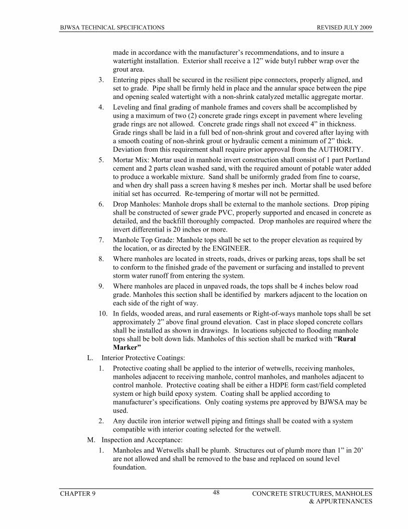
BJWSA TECHNICAL SPECIFICATIONS REVISED JULY 2009
CHAPTER 9 CONCRETE STRUCTURES, MANHOLES & APPURTENANCES
48
made in accordance with the manufacturer’s recommendations, and to insure a watertight installation. Exterior shall receive a 12” wide butyl rubber wrap over the grout area.
3. Entering pipes shall be secured in the resilient pipe connectors, properly aligned, and set to grade. Pipe shall be firmly held in place and the annular space between the pipe and opening sealed watertight with a non-shrink catalyzed metallic aggregate mortar.
4. Leveling and final grading of manhole frames and covers shall be accomplished by using a maximum of two (2) concrete grade rings except in pavement where leveling grade rings are not allowed. Concrete grade rings shall not exceed 4” in thickness. Grade rings shall be laid in a full bed of non-shrink grout and covered after laying with a smooth coating of non-shrink grout or hydraulic cement a minimum of 2” thick. Deviation from this requirement shall require prior approval from the AUTHORITY.
5. Mortar Mix: Mortar used in manhole invert construction shall consist of 1 part Portland cement and 2 parts clean washed sand, with the required amount of potable water added to produce a workable mixture. Sand shall be uniformly graded from fine to coarse, and when dry shall pass a screen having 8 meshes per inch. Mortar shall be used before initial set has occurred. Re-tempering of mortar will not be permitted.
6. Drop Manholes: Manhole drops shall be external to the manhole sections. Drop piping shall be constructed of sewer grade PVC, properly supported and encased in concrete as detailed, and the backfill thoroughly compacted. Drop manholes are required where the invert differential is 20 inches or more.
7. Manhole Top Grade: Manhole tops shall be set to the proper elevation as required by the location, or as directed by the ENGINEER.
8. Where manholes are located in streets, roads, drives or parking areas, tops shall be set to conform to the finished grade of the pavement or surfacing and installed to prevent storm water runoff from entering the system.
9. Where manholes are placed in unpaved roads, the tops shall be 4 inches below road grade. Manholes this section shall be identified by markers adjacent to the location on each side of the right of way.
10. In fields, wooded areas, and rural easements or Right-of-ways manhole tops shall be set approximately 2” above final ground elevation. Cast in place sloped concrete collars shall be installed as shown in drawings. In locations subjected to flooding manhole tops shall be bolt down lids. Manholes of this section shall be marked with “Rural Marker”
L. Interior Protective Coatings: 1. Protective coating shall be applied to the interior of wetwells, receiving manholes,
manholes adjacent to receiving manhole, control manholes, and manholes adjacent to control manhole. Protective coating shall be either a HDPE form cast/field completed system or high build epoxy system. Coating shall be applied according to manufacturer’s specifications. Only coating systems pre approved by BJWSA may be used.
2. Any ductile iron interior wetwell piping and fittings shall be coated with a system compatible with interior coating selected for the wetwell.
M. Inspection and Acceptance: 1. Manholes and Wetwells shall be plumb. Structures out of plumb more than 1” in 20’
are not allowed and shall be removed to the base and replaced on sound level foundation.

BJWSA TECHNICAL SPECIFICATIONS REVISED JULY 2009
CHAPTER 9 CONCRETE STRUCTURES, MANHOLES & APPURTENANCES
49
2. Manholes shall be true circles of acceptable concrete work with properly corbel tops, satisfactory inverts, complete interior coatings where required and properly placed frames, covers and steps. All leaks in manholes shall be repaired to the satisfaction of the AUTHORITY, prior to acceptance.
9.3 TESTS OF STRUCTURES:
A. Prior to backfill, each cast-in-place or prestressed concrete tank, basin or other liquid retaining structure shall be tested by filling the structure with clear water to its intended operating level or a greater level as directed by the ENGINEER, and letting it stand for at least 24 hours. All wall castings, sleeves, and other openings shall be plugged temporarily during the test period.
B. During cold weather, the CONTRACTOR shall take measures to insure that ice does not form on or in the structure prior to installation. These measures shall be submitted to the ENGINEER for approval.
C. All exterior surfaces shall be examined for leakage. Leakage is not allowed. If leakage exceeds 0.3% in 24 hours, the work shall be repaired by draining the structure and removing and replacing the defective areas, or by other methods as approved by the ENGINEER, and then performing a second leakage test.
D. In cast-in-place structures, hairline cracks that leak shall be enlarged to a V-shaped groove, 1-inch wide at the surface by 1-inch deep, and repaired to the satisfaction of the ENGINEER. Cracks may also be pressure grouted if required by the ENGINEER.
E. All repairs to prestressed tanks shall be made in strict accordance with the recommendations of the tank constructor.
F. Disposal of water after testing shall be satisfactory to the ENGINEER. G. Repair and retesting of the structure shall continue until leakage is within the allowable
limits and all leaks are repaired to the satisfaction of the ENGINEER. H. Unless otherwise specified, all expenses of the leakage test, including measuring devices,
temporary plugs, repairs and retesting, shall be paid for by the CONTRACTOR at no additional cost to the OWNER. Water necessary for the first leak test will be furnished by the OWNER, at no cost to the CONTRACTOR. Water used in retesting shall be paid for by the CONTRACTOR.
I. If any structure fails to pass the leakage test after five times, the entire structure shall be removed and rebuilt at no additional cost to the OWNER; such rebuilt structure shall be subject to all leakage test requirements as specified herein.
END OF SECTION
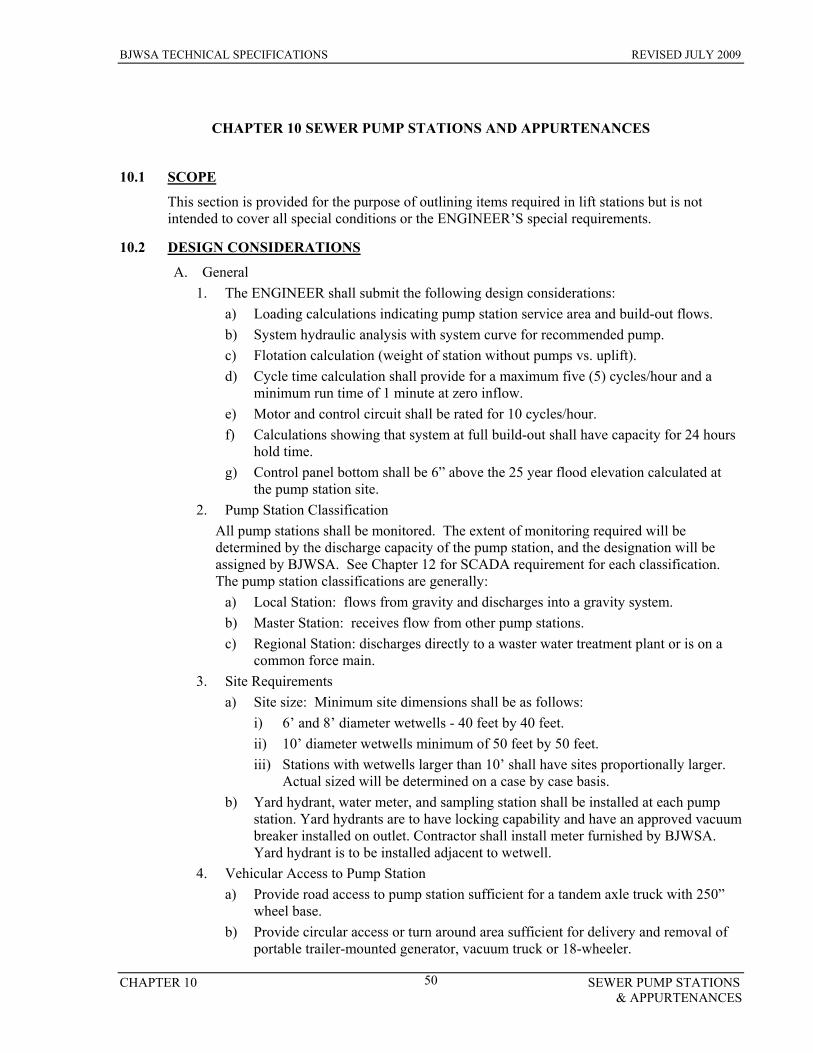
BJWSA TECHNICAL SPECIFICATIONS REVISED JULY 2009
CHAPTER 10 SEWER PUMP STATIONS & APPURTENANCES
50
CHAPTER 10 SEWER PUMP STATIONS AND APPURTENANCES
10.1 SCOPE
This section is provided for the purpose of outlining items required in lift stations but is not intended to cover all special conditions or the ENGINEER’S special requirements.
10.2 DESIGN CONSIDERATIONS
A. General 1. The ENGINEER shall submit the following design considerations:
a) Loading calculations indicating pump station service area and build-out flows. b) System hydraulic analysis with system curve for recommended pump. c) Flotation calculation (weight of station without pumps vs. uplift). d) Cycle time calculation shall provide for a maximum five (5) cycles/hour and a
minimum run time of 1 minute at zero inflow. e) Motor and control circuit shall be rated for 10 cycles/hour. f) Calculations showing that system at full build-out shall have capacity for 24 hours
hold time. g) Control panel bottom shall be 6” above the 25 year flood elevation calculated at
the pump station site. 2. Pump Station Classification
All pump stations shall be monitored. The extent of monitoring required will be determined by the discharge capacity of the pump station, and the designation will be assigned by BJWSA. See Chapter 12 for SCADA requirement for each classification. The pump station classifications are generally:
a) Local Station: flows from gravity and discharges into a gravity system. b) Master Station: receives flow from other pump stations. c) Regional Station: discharges directly to a waster water treatment plant or is on a
common force main. 3. Site Requirements
a) Site size: Minimum site dimensions shall be as follows: i) 6’ and 8’ diameter wetwells - 40 feet by 40 feet. ii) 10’ diameter wetwells minimum of 50 feet by 50 feet. iii) Stations with wetwells larger than 10’ shall have sites proportionally larger.
Actual sized will be determined on a case by case basis. b) Yard hydrant, water meter, and sampling station shall be installed at each pump
station. Yard hydrants are to have locking capability and have an approved vacuum breaker installed on outlet. Contractor shall install meter furnished by BJWSA. Yard hydrant is to be installed adjacent to wetwell.
4. Vehicular Access to Pump Station a) Provide road access to pump station sufficient for a tandem axle truck with 250”
wheel base. b) Provide circular access or turn around area sufficient for delivery and removal of
portable trailer-mounted generator, vacuum truck or 18-wheeler.

BJWSA TECHNICAL SPECIFICATIONS REVISED JULY 2009
CHAPTER 10 SEWER PUMP STATIONS & APPURTENANCES
51
c) All turning radii should be set at 60’. d) Site shall be serviced by an all weather road with top of site a minimum of 6”
above adjacent paved road. 5. Design and Construction considerations:
a) Wetwell (this section applies to submersible and above ground) i) Concrete shall meet the requirements as specified in Chapter 9. Interior
surface of the wet well and exterior of discharge piping shall be coated with hydrogen sulfide resistant coating. Refer to Interior Protective Coatings of Chapter 9.
ii) Bottom slab of the wet well shall be set on a minimum of 12” base made of crushed stone. All over-excavated area below the wet well bottom shall be filled with crushed stone or flowable fill as directed by the ENGINEER.
iii) Wet well bottom shall be constructed to provide a hopper or fillet bottom. Concrete bricks may be used as filler to form hopper bottom provided minimum of 6” grout cover over bricks is maintained.
iv) Top of wetwell shall be one foot (1’) above adjacent paved road or surrounding grade. A Registered Land Surveyor shall confirm the difference and stamp the elevation on a 2” diameter Standard Brass Benchmark embedded into the wetwell top. Pump station site is to be higher than final grade within adjacent 10’ of the pump station. Drainage across the pump station is not allowed.
v) Wet well hatches shall be of heavy gauge aluminum with aluminum or 316 stainless steel support bracing, accessories. Minimum clear opening size shall be 32” by 48” single door style. All hatches shall be equipped with a hinged safety grate. Refer to Chapter 13 for a list of approved manufacturers.
vi) Flush vent shall be a 4.75” square opening framed with ¼”x1”x 1” angle and covered by 1”x 1” x 1” aluminum grating 6” square.
vii) Wet well level sensor hangers shall be hung on the edge of the safety grate hatch away from inlet piping and shall be supplied in accordance with the approved manufacturers in Chapter 13.
viii) All bolts, nuts, anchors, washers, and other hardware utilized in the wet well shall be 316 stainless steel.
b) Influent pipe shall extend a minimum of 2” and a maximum of 3” inside the basin. c) The bypass suction leg (4” PVC) shall terminate in a MJ 90 anchored in fillet. It
shall extend up through Wetwell top. The bypass piping shall turn 90 degrees and terminate with a male quick disconnect fitting with cap just under discharge piping.
d) All piping in wet well shall be coated with hydrogen sulfide resistant coating. Refer to: Interior Protective Coatings of Chapter 9.
e) Pump station location shall be optimized for both elevation and power supply. 6. Piping and Fittings
a) Piping within wet well shall be flanged. b) All valves shall be resilient seat, plug type, and open left (counter-clockwise).
Valves located above ground shall be hand-wheel operated. c) Discharge riser piping shall be C900 SDR 18 d) Above ground pipes shall be supported with a 304 SS or HD Galvanized adjustable

BJWSA TECHNICAL SPECIFICATIONS REVISED JULY 2009
CHAPTER 10 SEWER PUMP STATIONS & APPURTENANCES
52
pipe support. The Support base shall have screw adjustment range of not less than 12 inches, and 4 bolt holes with minimum diameter of 9/16 inches, and the saddle shall match the curvature of the pipe to be supported.
e) The pump discharge shall be equipped with a pressure gauge plug in assembly: i) All components are to be Stainless Steel ii) Piping to owner gauge shall be 2” x 1” tee, 1” x 1” nipple, 1” ball valve, 1”
make NPT Universal coupling, and Universal blank with seciring nylon lanyard attached to piping. Universal coupling must be resistant to corrosion by sewer gasses (brass, SS, and HDG are acceptable)
f) All above ground piping shall be coated with a minimum of three coats of Tnemec epoxy paint. The topcoat shall be color “Hunter Green”. Total system minimum dry film thickness of 16 mils is to be achieved. Piping surface shall be prepared, primed, intermediate coated, and topcoated per manufacturer’s instructions. See Chapter 13 for approved epoxy coatings.
B. Submersible Pump Station Site Requirements 1. All design considerations from 10.2.A apply to this section. 2. Site Requirements
a) A night area light and alarm light shall be installed a minimum of 12-FT above finished grade and mounted on a timber light pole treated to 2.5-LB CCA. Yard light shall be 120V 500W Quartz or Halogen floodlight pointed at the control panel. Light shall be controlled by a switch mounted in control panel, not the circuit breaker.
b) The motor control center shall be located outside and facing toward the wet well with an adequate distance from the wet well to avoid accidental fall.
c) Fencing of Lift Station Site is required. i) Area to be fenced shall start 1.5’ inside property line. ii) Fence Materials
1. All material shall be Class I Hot-dipped Galvanized Coated. Vinyl coated fencing may be installed for aesthetic purposes.
2. Fabric shall be six (6) feet high, ends barbed, commercial grade nine (9) gauge, two inch (2”) mesh installed between 1” and 3” above finished grade.
3. End, corner, and pull post shall be 3” OD Schedule 40 steel pipe. Provide water tight closure caps on all posts.
4. Line posts shall be 2-1/2” OD Schedule 40 steel pipe. Provide water tight closure caps on all post. Top posts shall be 1-5/8” OD Schedule 40 steel pipe.
5. Bottom tension wire shall be 7-gauge spring coil wire. 6. Gatepost shall be 3” OD Schedule 40 steel pipe. Provide water tight
closure caps on all post. 7. Gate shall be a pair of 8’-0” long (16’ total width) 6 feet high sections
constructed of 2 inch OD pipe. Gate shall be equipped with a prop post center latch and hasp assembly. A ground anchor cast in concrete shall be provided. Gates shall be factory fabricated, coated, and equipped with gate holders. Duckbill backstops shall be provided for swing side of both gate sections.
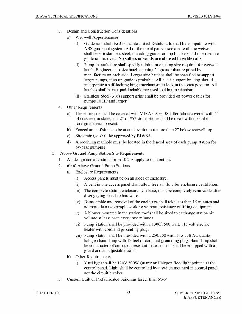
BJWSA TECHNICAL SPECIFICATIONS REVISED JULY 2009
CHAPTER 10 SEWER PUMP STATIONS & APPURTENANCES
53
3. Design and Construction Considerations a) Wet well Appurtenances
i) Guide rails shall be 316 stainless steel. Guide rails shall be compatible with ABS guide rail system. All of the metal parts associated with the wetwell shall be 316 stainless steel, including guide rail top brackets and intermediate guide rail brackets. No splices or welds are allowed in guide rails.
ii) Pump manufacture shall specify minimum opening size required for wetwell hatch. Engineer is to size hatch opening 2” greater than required by manufacture on each side. Larger size hatches shall be specified to support larger pumps, if an up grade is probable. All hatch support bracing should incorporate a self-locking hinge mechanism to lock in the open position. All hatches shall have a pad-lockable recessed locking mechanism.
iii) Stainless Steel (316) support grips shall be provided on power cables for pumps 10 HP and larger.
4. Other Requirements a) The entire site shall be covered with MIRAFIX 600X filter fabric covered with 4”
of crusher run stone, and 2” of #57 stone. Stone shall be clean with no soil or foreign material present.
b) Fenced area of site is to be at an elevation not more than 2” below wetwell top. c) Site drainage shall be approved by BJWSA. d) A receiving manhole must be located in the fenced area of each pump station for
by-pass pumping. C. Above Ground Pump Station Site Requirements
1. All design considerations from 10.2.A apply to this section. 2. 6’x6’ Above Ground Pump Stations
a) Enclosure Requirements i) Access panels must be on all sides of enclosure. ii) A vent in one access panel shall allow free air-flow for enclosure ventilation. iii) The complete station enclosure, less base, must be completely removable after
disengaging reusable hardware. iv) Disassemble and removal of the enclosure shall take less than 15 minutes and
no more than two people working without assistance of lifting equipment. v) A blower mounted in the station roof shall be sized to exchange station air
volume at least once every two minutes. vi) Pump Station shall be provided with a 1300/1500 watt, 115 volt electric
heater with cord and grounding plug. vii) Pump Station shall be provided with a 250/500 watt, 115 volt AC quartz
halogen hand lamp with 12 feet of cord and grounding plug. Hand lamp shall be constructed of corrosion resistant materials and shall be equipped with a guard and an adjustable stand.
b) Other Requirements i) Yard light shall be 120V 500W Quartz or Halogen floodlight pointed at the
control panel. Light shall be controlled by a switch mounted in control panel, not the circuit breaker.
3. Custom Built or Prefabricated buildings larger than 6’x6’

BJWSA TECHNICAL SPECIFICATIONS REVISED JULY 2009
CHAPTER 10 SEWER PUMP STATIONS & APPURTENANCES
54
a) Access to Pump Station i) Layout site to allow
1. Access of boom truck to double doors or rollup door. 2. Access by vacuum truck or tanker with 40’ trailer to within 15’ of
wetwell hatch. ii) Pump Station enclosure is to be accessible with truck to side of building with
rollup door and side of building with swing door. b) Enclosure Requirements
i) Enclosure shall have a minimum R-13 insulation factor and shall be capable of withstanding 125 mph wind loads.
ii) The pitch of the roof shall be sufficient for good moisture drainage. iii) Enclosure shall be provided with one 3’-0” wide x 6’-8” entrance door. iv) Enclosure shall be provided with one 8’ wide x 6’-8” high rolling service
door. v) Enclosure shall have floor sloped to a drain. vi) Lighting inside enclosure shall provide a minimum of two (2) watts
illumination per square foot in most dimly lit area. vii) Enclosure shall be provided with two (2), duplex, GFCI receptacles, internal
and external, mounted 48” above finished floor. External receptacle shall be located adjacent to WW hatch.
viii) Enclosure shall have a thermostatically controlled, 120 VAC, exhaust fan with screen and weatherproof shutters installed in the wall approximately opposite a fresh air intake vent. The fan shall have a minimum capacity of 1600 CFM at free air and be capable of changing the air in the enclosure a minimum of six times per hour.
ix) Enclosure shall be provided with high capacity electric blower type heater for protection of the internal equipment. The heater shall maintain an inside/outside differential temperature of 30 degrees F.
x) Enclosure shall have engine assembly and space for one additional pump and motor to be added in the future. This space shall be shown as “future” on plans.
c) Other Requirements i) Concrete bollards shall be placed around buried fuel tank and generator. ii) A receiving manhole must be located within 15’ of wetwell and within
vehicle access area. iii) Provide a flow meter with transmitter inside of building. iv) Provide a pressure transmitter inside of building. v) Provide an external light on all side of the enclosure.
10.3 PUMPS AND MOTORS
A. General 1. Pump and motor shall be shipped with non-wicking electrical power cable, over-heat
cable, and seal-failure cable, factory installed and tested. Cut ends are to be factory sealed and tagged for shopping. Each pump shall have only one cable.
2. Pump station system design shall require the selected motor to operate within 10
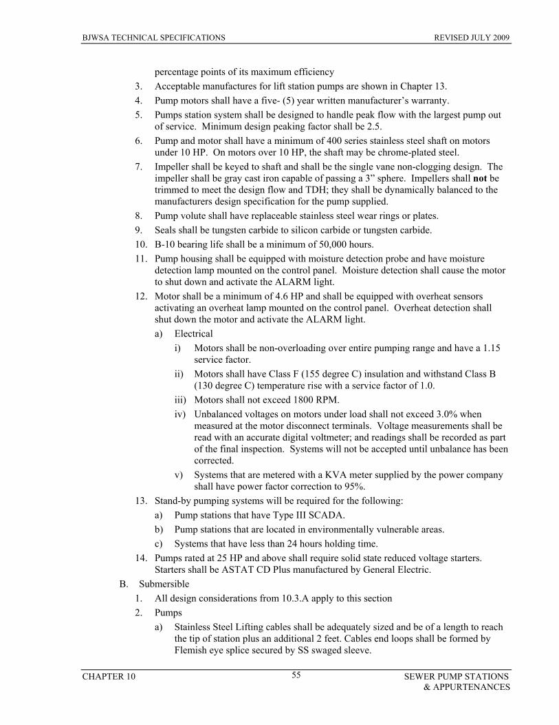
BJWSA TECHNICAL SPECIFICATIONS REVISED JULY 2009
CHAPTER 10 SEWER PUMP STATIONS & APPURTENANCES
55
percentage points of its maximum efficiency 3. Acceptable manufactures for lift station pumps are shown in Chapter 13. 4. Pump motors shall have a five- (5) year written manufacturer’s warranty. 5. Pumps station system shall be designed to handle peak flow with the largest pump out
of service. Minimum design peaking factor shall be 2.5. 6. Pump and motor shall have a minimum of 400 series stainless steel shaft on motors
under 10 HP. On motors over 10 HP, the shaft may be chrome-plated steel. 7. Impeller shall be keyed to shaft and shall be the single vane non-clogging design. The
impeller shall be gray cast iron capable of passing a 3” sphere. Impellers shall not be trimmed to meet the design flow and TDH; they shall be dynamically balanced to the manufacturers design specification for the pump supplied.
8. Pump volute shall have replaceable stainless steel wear rings or plates. 9. Seals shall be tungsten carbide to silicon carbide or tungsten carbide. 10. B-10 bearing life shall be a minimum of 50,000 hours. 11. Pump housing shall be equipped with moisture detection probe and have moisture
detection lamp mounted on the control panel. Moisture detection shall cause the motor to shut down and activate the ALARM light.
12. Motor shall be a minimum of 4.6 HP and shall be equipped with overheat sensors activating an overheat lamp mounted on the control panel. Overheat detection shall shut down the motor and activate the ALARM light. a) Electrical
i) Motors shall be non-overloading over entire pumping range and have a 1.15 service factor.
ii) Motors shall have Class F (155 degree C) insulation and withstand Class B (130 degree C) temperature rise with a service factor of 1.0.
iii) Motors shall not exceed 1800 RPM. iv) Unbalanced voltages on motors under load shall not exceed 3.0% when
measured at the motor disconnect terminals. Voltage measurements shall be read with an accurate digital voltmeter; and readings shall be recorded as part of the final inspection. Systems will not be accepted until unbalance has been corrected.
v) Systems that are metered with a KVA meter supplied by the power company shall have power factor correction to 95%.
13. Stand-by pumping systems will be required for the following: a) Pump stations that have Type III SCADA. b) Pump stations that are located in environmentally vulnerable areas. c) Systems that have less than 24 hours holding time.
14. Pumps rated at 25 HP and above shall require solid state reduced voltage starters. Starters shall be ASTAT CD Plus manufactured by General Electric.
B. Submersible 1. All design considerations from 10.3.A apply to this section 2. Pumps
a) Stainless Steel Lifting cables shall be adequately sized and be of a length to reach the tip of station plus an additional 2 feet. Cables end loops shall be formed by Flemish eye splice secured by SS swaged sleeve.

BJWSA TECHNICAL SPECIFICATIONS REVISED JULY 2009
CHAPTER 10 SEWER PUMP STATIONS & APPURTENANCES
56
Minimum requirement and size is as follows: i) Cable, 3/16” SS ii) Chain, 18” – 1/4” SS iii) Shackle, 5/16” SS screw pin iv) Thimble SS, and Nicro press sleeve to fit Grip Eye System by ABS
3. Pumps shall mount on single stainless steel guide rail system compatible to ABS pumps.
4. Wetwell Depth of wetwell shall be set to accommodate all conditions set forth in Chapter 10.2 and the following Level Control System parameters:
a) ALARM (Low): Set at the higher of 12” below OFF and 8” above the minimum submergence recommended by pump manufacturer.
b) OFF: Set no lower than the lifting eye of the pump. c) LEAD ON: Minimum elevation determined by minimum run time allowed and
OFF. d) LAG ON: Provide a minimum of one-foot (1’) above LEAD ON e) ALARM (High): Set one-foot (1’) minimum above the LAG ON. f) INFLUENT PIPE: Set a minimum of six inches (6”) above the ALARM (high).
C. Above Ground 1. All design considerations from 10.3.A apply to this section 2. Pumps
a) Pumps shall be horizontal, self-priming sewage pumps, specifically designed for pumping raw, unscreened, domestic sanitary sewage.
3. Wet Well Depth of wetwell shall be set to accommodate all conditions set forth in Chapter 10.2 and the following Level Control System parameters. a) ALARM (Low) Set at 2” above top of minimum cover required over suction pipe
opening b) OFF: Minimum as specified by the pump manufacturer c) LEAD ON: Minimum as specified by the pump manufacturer d) LAG ON: 6” minimum above LEAD ON e) ALARM (High): Set one-foot (1’) minimum above the LAG ON f) INFLUENT PIPE: Set a minimum of six inches (6”) above the ALARM (high).
4. Drive Motors – Electric a) General Description
i) Motor to be horizontal, totally enclosed, fan cooled (TEFC), induction type, with Class F insulation, normal starting torque and low starting current characteristics, NEMA Design B, 1.15 service factor.
ii) Motor shall not be overloaded at the design condition or at any head in the operating range as specified.
iii) Equip all motors intended for outdoor installation with 120-volt space heaters having leads terminating in the main terminal box.
iv) Provide motor in current NEMA design cast iron frame with copper windings,
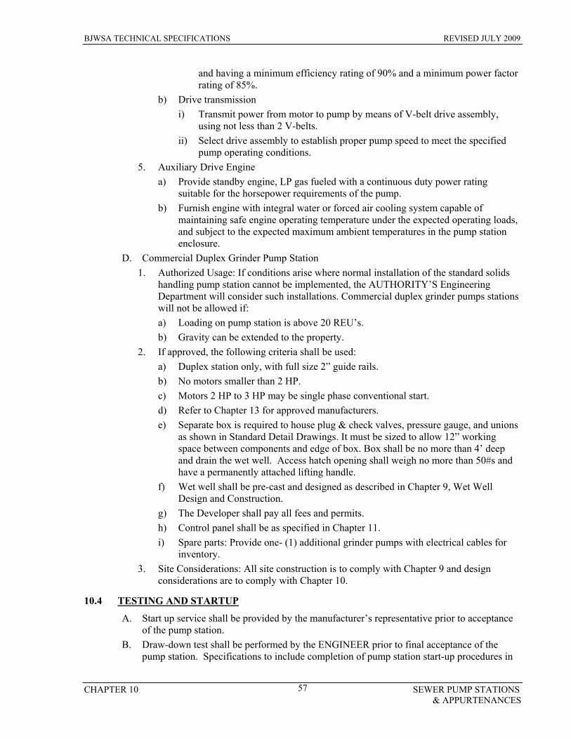
BJWSA TECHNICAL SPECIFICATIONS REVISED JULY 2009
CHAPTER 10 SEWER PUMP STATIONS & APPURTENANCES
57
and having a minimum efficiency rating of 90% and a minimum power factor rating of 85%.
b) Drive transmission i) Transmit power from motor to pump by means of V-belt drive assembly,
using not less than 2 V-belts. ii) Select drive assembly to establish proper pump speed to meet the specified
pump operating conditions. 5. Auxiliary Drive Engine
a) Provide standby engine, LP gas fueled with a continuous duty power rating suitable for the horsepower requirements of the pump.
b) Furnish engine with integral water or forced air cooling system capable of maintaining safe engine operating temperature under the expected operating loads, and subject to the expected maximum ambient temperatures in the pump station enclosure.
D. Commercial Duplex Grinder Pump Station 1. Authorized Usage: If conditions arise where normal installation of the standard solids
handling pump station cannot be implemented, the AUTHORITY’S Engineering Department will consider such installations. Commercial duplex grinder pumps stations will not be allowed if: a) Loading on pump station is above 20 REU’s. b) Gravity can be extended to the property.
2. If approved, the following criteria shall be used: a) Duplex station only, with full size 2” guide rails. b) No motors smaller than 2 HP. c) Motors 2 HP to 3 HP may be single phase conventional start. d) Refer to Chapter 13 for approved manufacturers. e) Separate box is required to house plug & check valves, pressure gauge, and unions
as shown in Standard Detail Drawings. It must be sized to allow 12” working space between components and edge of box. Box shall be no more than 4’ deep and drain the wet well. Access hatch opening shall weigh no more than 50#s and have a permanently attached lifting handle.
f) Wet well shall be pre-cast and designed as described in Chapter 9, Wet Well Design and Construction.
g) The Developer shall pay all fees and permits. h) Control panel shall be as specified in Chapter 11. i) Spare parts: Provide one- (1) additional grinder pumps with electrical cables for
inventory. 3. Site Considerations: All site construction is to comply with Chapter 9 and design
considerations are to comply with Chapter 10.
10.4 TESTING AND STARTUP
A. Start up service shall be provided by the manufacturer’s representative prior to acceptance of the pump station.
B. Draw-down test shall be performed by the ENGINEER prior to final acceptance of the pump station. Specifications to include completion of pump station start-up procedures in
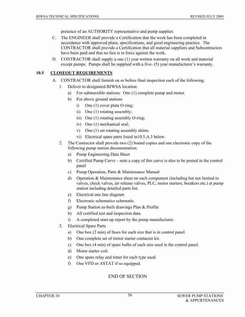
BJWSA TECHNICAL SPECIFICATIONS REVISED JULY 2009
CHAPTER 10 SEWER PUMP STATIONS & APPURTENANCES
58
presence of an AUTHORITY representative and pump supplier. C. The ENGINEER shall provide a Certification that the work has been completed in
accordance with approved plans, specifications, and good engineering practice. The CONTRACTOR shall provide a Certification that all material suppliers and Subcontractors have been paid and that no lien is in force against the work.
D. CONTRACTOR shall supply a one (1) year written warranty on all work and material except pumps. Pumps shall be supplied with a five- (5) year manufacturer’s warranty.
10.5 CLOSEOUT REQUIREMENTS
A. CONTRACTOR shall furnish on or before final inspection each of the following: 1. Deliver to designated BJWSA location:
a) For submersible stations: One (1) complete pump and motor. b) For above ground stations
i) One (1) cover plate O-ring; ii) One (1) rotating assembly; iii) One (1) rotating assembly O-ring; iv) One (1) mechanical seal; v) One (1) set rotating assembly shims. vi) Electrical spare parts listed in10.5.A.3 below.
2. The Contractor shall provide two (2) bound copies and one electronic copy of the following pump station documentation: a) Pump Engineering Data Sheet b) Certified Pump Curve – note a copy of this curve is also to be posted in the control
panel c) Pump Operation, Parts & Maintenance Manual d) Operation & Maintenance sheet on each component (including but not limited to
valves, check valves, air release valves, PLC, motor starters, breakers etc.) at pump station including detailed parts list.
e) Electrical one line diagram f) Electronic schematics schematic. g) Pump Station as-built drawings Plan & Profile h) All certified test and inspection data. i) A completed start-up report by the pump manufacturer.
3. Electrical Spare Parts a) One box (2 min) of fuses for each size that is in control panel. b) One complete set of motor starter contactor kit. c) One box (4 min) of spare bulbs of each size used in the control panel. d) Motor starter coil. e) One spare relay and timer for each type used. f) One VFD or ASTAT if so equipped.
END OF SECTION

BJWSA TECHNICAL SPECIFICATIONS REVISED JULY 2009
CHAPTER 11 SEWER PUMP STATION ELECTRICAL 59
CHAPTER 11 SEWER PUMP STATION ELECTRICAL
11.1 GENERAL
A. Electrical work shall be as indicated on the drawings, including all items which may be reasonably implied in order to provide a complete and operational system
B. All work shall be in accordance with the most current edition of the National Electric Code, as well as local Inspection Department requirements that has jurisdiction.
C. All work must be performed using a licensed electrician. D. Obtain necessary permits and pay associated fees prior to starting work. E. Make necessary arrangements with the utility for power service and arrange for temporary
power as required. F. Power Supply
1. Single phase power is allowed for motors 5 hp or less. 2. 3 phase is required on all pumps greater than 5 hp, if pumps are optimized for elevation
& 3 phase power is not available, then VFD’s will be approved on a case by case basis by BJWSA.
G. All power lines within the site shall be underground. No overhead power line will be allowed to cross the site.
H. Main power lines shall be stranded copper and shall either be THHN, THWN, RHW, or XHHW.
I. Underground conduit from junction boxes shall be a minimum of 2-inch Schedule 80 PVC. Schedule 40 PVC may also be used if encased in concrete. Above ground conduit shall be schedule 40 hot dipped galvanized conduit. Separate conduits shall be provided for each pump power cable and one conduit for all float wires. Conduits inside the pump station wet well shall extend to the closest end of the access hatch and terminate with bell ends or bushings.
J. Motor starting equipment and circuit breakers shall be G.E. Main circuit breaker disconnect shall be housed in a separate locking NEMA 4x stainless steel enclosure mounted on the control panel bracket. Main breaker shall have a lockable externally mounted control lever and shall be rated for service entrance application. The minimum size shall be 20X16X8 for 100 amp and 24X16X8 over 100 amp. Voltage shall be clearly labeled on disconnect.
K. A generator receptacle shall be provided and mounted on a separate cast aluminum enclosure and wired to match existing generator. Generation system shall be tested utilizing BJWSA’s generator prior to acceptance. A receptacle cover plate must be screwed or bolted on with draw down bolts. All mounting hardware shall be stainless steel.
1. 100 amp receptacle (4 wire – 4 pole) with stainless steel hooks and wing nuts for less than 9.5 HP
2. 200 amp receptacle (4 wire – 4 pole) for 9.5 HP and larger L. Stainless Steel Enclosed Lightning/Surge Arrestors
1. Shall be connected to the main disconnect for each phase of incoming service. 2. Shall to be mounted outside the main control panel 3. Shall have a 160,000 surge current rating,
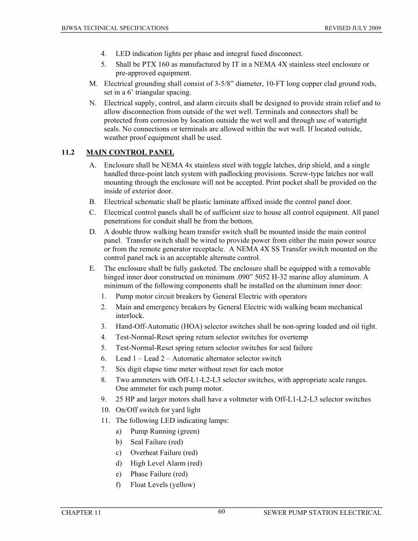
BJWSA TECHNICAL SPECIFICATIONS REVISED JULY 2009
CHAPTER 11 SEWER PUMP STATION ELECTRICAL 60
4. LED indication lights per phase and integral fused disconnect. 5. Shall be PTX 160 as manufactured by IT in a NEMA 4X stainless steel enclosure or
pre-approved equipment. M. Electrical grounding shall consist of 3-5/8” diameter, 10-FT long copper clad ground rods,
set in a 6’ triangular spacing. N. Electrical supply, control, and alarm circuits shall be designed to provide strain relief and to
allow disconnection from outside of the wet well. Terminals and connectors shall be protected from corrosion by location outside the wet well and through use of watertight seals. No connections or terminals are allowed within the wet well. If located outside, weather proof equipment shall be used.
11.2 MAIN CONTROL PANEL
A. Enclosure shall be NEMA 4x stainless steel with toggle latches, drip shield, and a single handled three-point latch system with padlocking provisions. Screw-type latches nor wall mounting through the enclosure will not be accepted. Print pocket shall be provided on the inside of exterior door.
B. Electrical schematic shall be plastic laminate affixed inside the control panel door. C. Electrical control panels shall be of sufficient size to house all control equipment. All panel
penetrations for conduit shall be from the bottom. D. A double throw walking beam transfer switch shall be mounted inside the main control
panel. Transfer switch shall be wired to provide power from either the main power source or from the remote generator receptacle. A NEMA 4X SS Transfer switch mounted on the control panel rack is an acceptable alternate control.
E. The enclosure shall be fully gasketed. The enclosure shall be equipped with a removable hinged inner door constructed on minimum .090” 5052 H-32 marine alloy aluminum. A minimum of the following components shall be installed on the aluminum inner door:
1. Pump motor circuit breakers by General Electric with operators 2. Main and emergency breakers by General Electric with walking beam mechanical
interlock. 3. Hand-Off-Automatic (HOA) selector switches shall be non-spring loaded and oil tight. 4. Test-Normal-Reset spring return selector switches for overtemp 5. Test-Normal-Reset spring return selector switches for seal failure 6. Lead 1 – Lead 2 – Automatic alternator selector switch 7. Six digit elapse time meter without reset for each motor 8. Two ammeters with Off-L1-L2-L3 selector switches, with appropriate scale ranges.
One ammeter for each pump motor. 9. 25 HP and larger motors shall have a voltmeter with Off-L1-L2-L3 selector switches 10. On/Off switch for yard light 11. The following LED indicating lamps:
a) Pump Running (green) b) Seal Failure (red) c) Overheat Failure (red) d) High Level Alarm (red) e) Phase Failure (red) f) Float Levels (yellow)
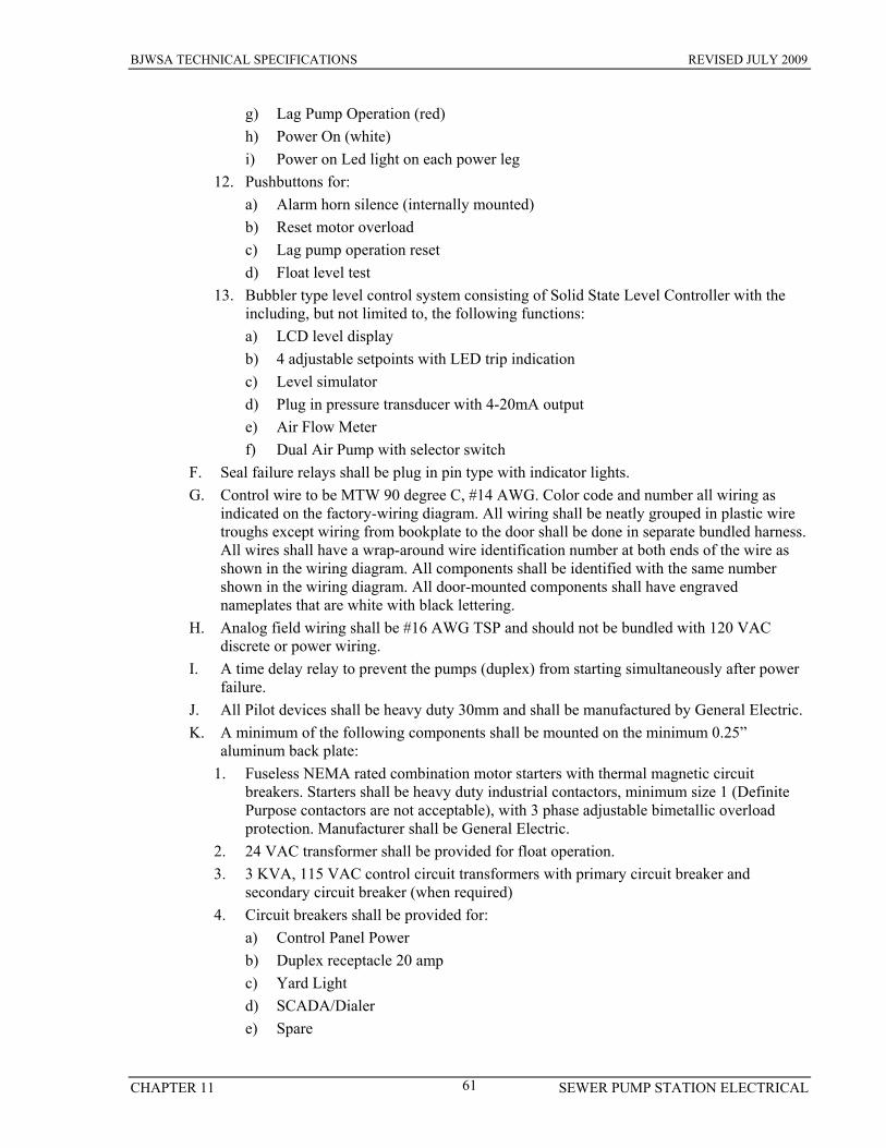
BJWSA TECHNICAL SPECIFICATIONS REVISED JULY 2009
CHAPTER 11 SEWER PUMP STATION ELECTRICAL 61
g) Lag Pump Operation (red) h) Power On (white) i) Power on Led light on each power leg
12. Pushbuttons for: a) Alarm horn silence (internally mounted) b) Reset motor overload c) Lag pump operation reset d) Float level test
13. Bubbler type level control system consisting of Solid State Level Controller with the including, but not limited to, the following functions: a) LCD level display b) 4 adjustable setpoints with LED trip indication c) Level simulator d) Plug in pressure transducer with 4-20mA output e) Air Flow Meter f) Dual Air Pump with selector switch
F. Seal failure relays shall be plug in pin type with indicator lights. G. Control wire to be MTW 90 degree C, #14 AWG. Color code and number all wiring as
indicated on the factory-wiring diagram. All wiring shall be neatly grouped in plastic wire troughs except wiring from bookplate to the door shall be done in separate bundled harness. All wires shall have a wrap-around wire identification number at both ends of the wire as shown in the wiring diagram. All components shall be identified with the same number shown in the wiring diagram. All door-mounted components shall have engraved nameplates that are white with black lettering.
H. Analog field wiring shall be #16 AWG TSP and should not be bundled with 120 VAC discrete or power wiring.
I. A time delay relay to prevent the pumps (duplex) from starting simultaneously after power failure.
J. All Pilot devices shall be heavy duty 30mm and shall be manufactured by General Electric. K. A minimum of the following components shall be mounted on the minimum 0.25”
aluminum back plate: 1. Fuseless NEMA rated combination motor starters with thermal magnetic circuit
breakers. Starters shall be heavy duty industrial contactors, minimum size 1 (Definite Purpose contactors are not acceptable), with 3 phase adjustable bimetallic overload protection. Manufacturer shall be General Electric.
2. 24 VAC transformer shall be provided for float operation. 3. 3 KVA, 115 VAC control circuit transformers with primary circuit breaker and
secondary circuit breaker (when required) 4. Circuit breakers shall be provided for:
a) Control Panel Power b) Duplex receptacle 20 amp c) Yard Light d) SCADA/Dialer e) Spare
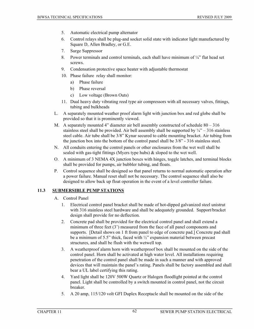
BJWSA TECHNICAL SPECIFICATIONS REVISED JULY 2009
CHAPTER 11 SEWER PUMP STATION ELECTRICAL 62
5. Automatic electrical pump alternator 6. Control relays shall be plug-and socket solid state with indicator light manufactured by
Square D, Allen Bradley, or G.E. 7. Surge Suppressor 8. Power terminals and control terminals, each shall have minimum of ¼” flat head set
screws. 9. Condensation protective space heater with adjustable thermostat 10. Phase failure relay shall monitor:
a) Phase failure b) Phase reversal c) Low voltage (Brown Outs)
11. Dual heavy duty vibrating reed type air compressors with all necessary valves, fittings, tubing and bulkheads
L. A separately mounted weather proof alarm light with junction box and red globe shall be provided so that it is prominently viewed.
M. A separately mounted 4” diameter air bell assembly constructed of schedule 80 – 316 stainless steel shall be provided. Air bell assembly shall be supported by ¼” – 316 stainless steel cable. Air tube shall be 3/8” Kynar secured to cable mounting bracket. Air tubing from the junction box into the bottom of the control panel shall be 3/8” - 316 stainless steel.
N. All conduits entering the control panels or other enclosures from the wet well shall be sealed with gas-tight fittings (Myers type hubs) & sloped to the wet well.
O. A minimum of 3 NEMA 4X junction boxes with hinges, toggle latches, and terminal blocks shall be provided for pumps, air bubbler tubing, and floats.
P. Control sequence shall be designed so that panel returns to normal automatic operation after a power failure. Manual reset shall not be necessary. The control sequence shall also be designed to allow back up float operation in the event of a level controller failure.
11.3 SUBMERSIBLE PUMP STATIONS
A. Control Panel 1. Electrical control panel bracket shall be made of hot-dipped galvanized steel unistrut
with 316 stainless steel hardware and shall be adequately grounded. Support/bracket design shall provide for no deflection.
2. Concrete pad shall be provided for the electrical control panel and shall extend a minimum of three feet (3’) measured from the face of all panel components and supports. [Detail shows on 1 ft from panel to edge of concrete pad.] Concrete pad shall be a minimum of 5.5” thick, faced with ½” expansion material between precast structures, and shall be flush with the wetwell top.
3. A weatherproof alarm horn with weatherproof box shall be mounted on the side of the control panel. Horn shall be activated at high water level. All installations requiring penetration of the control panel shall be made in such a manner and with approved devices that will maintain the panel’s rating. Panels shall be factory assembled and shall bear a UL label certifying this rating.
4. Yard light shall be 120V 500W Quartz or Halogen floodlight pointed at the control panel. Light shall be controlled by a switch mounted in control panel, not the circuit breaker.
5. A 20 amp, 115/120 volt GFI Duplex Receptacle shall be mounted on the side of the
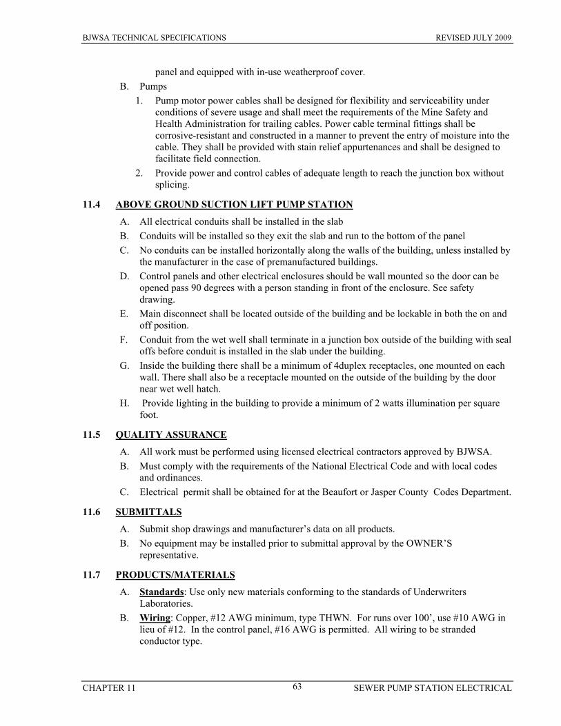
BJWSA TECHNICAL SPECIFICATIONS REVISED JULY 2009
CHAPTER 11 SEWER PUMP STATION ELECTRICAL 63
panel and equipped with in-use weatherproof cover. B. Pumps
1. Pump motor power cables shall be designed for flexibility and serviceability under conditions of severe usage and shall meet the requirements of the Mine Safety and Health Administration for trailing cables. Power cable terminal fittings shall be corrosive-resistant and constructed in a manner to prevent the entry of moisture into the cable. They shall be provided with stain relief appurtenances and shall be designed to facilitate field connection.
2. Provide power and control cables of adequate length to reach the junction box without splicing.
11.4 ABOVE GROUND SUCTION LIFT PUMP STATION
A. All electrical conduits shall be installed in the slab B. Conduits will be installed so they exit the slab and run to the bottom of the panel C. No conduits can be installed horizontally along the walls of the building, unless installed by
the manufacturer in the case of premanufactured buildings. D. Control panels and other electrical enclosures should be wall mounted so the door can be
opened pass 90 degrees with a person standing in front of the enclosure. See safety drawing.
E. Main disconnect shall be located outside of the building and be lockable in both the on and off position.
F. Conduit from the wet well shall terminate in a junction box outside of the building with seal offs before conduit is installed in the slab under the building.
G. Inside the building there shall be a minimum of 4duplex receptacles, one mounted on each wall. There shall also be a receptacle mounted on the outside of the building by the door near wet well hatch.
H. Provide lighting in the building to provide a minimum of 2 watts illumination per square foot.
11.5 QUALITY ASSURANCE
A. All work must be performed using licensed electrical contractors approved by BJWSA. B. Must comply with the requirements of the National Electrical Code and with local codes
and ordinances. C. Electrical permit shall be obtained for at the Beaufort or Jasper County Codes Department.
11.6 SUBMITTALS
A. Submit shop drawings and manufacturer’s data on all products. B. No equipment may be installed prior to submittal approval by the OWNER’S
representative.
11.7 PRODUCTS/MATERIALS
A. Standards: Use only new materials conforming to the standards of Underwriters Laboratories.
B. Wiring: Copper, #12 AWG minimum, type THWN. For runs over 100’, use #10 AWG in lieu of #12. In the control panel, #16 AWG is permitted. All wiring to be stranded conductor type.
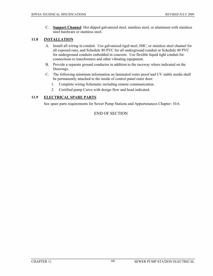
BJWSA TECHNICAL SPECIFICATIONS REVISED JULY 2009
CHAPTER 11 SEWER PUMP STATION ELECTRICAL 64
C. Support Channel: Hot dipped galvanized steel, stainless steel, or aluminum with stainless steel hardware or stainless steel.
11.8 INSTALLATION
A. Install all wiring in conduit. Use galvanized rigid steel, IMC, or stainless steel channel for all exposed runs, and Schedule 80 PVC for all underground conduit or Schedule 40 PVC for underground conduits embedded in concrete. Use flexible liquid tight conduit for connections to transformers and other vibrating equipment.
B. Provide a separate ground conductor in addition to the raceway where indicated on the Drawings.
C. The following minimum information on laminated water proof and UV stable media shall be permanently attached to the inside of control panel outer door:
1. Complete wiring Schematic including remote communication. 2. Certified pump Curve with design flow and head indicated.
11.9 ELECTRICAL SPARE PARTS
See spare parts requirements for Sewer Pump Stations and Appurtenances Chapter: 10.6.
END OF SECTION
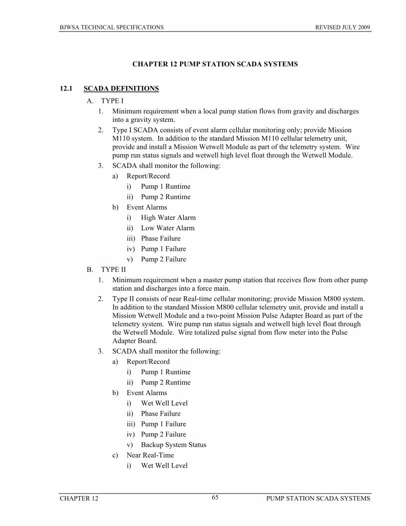
BJWSA TECHNICAL SPECIFICATIONS REVISED JULY 2009
CHAPTER 12 PUMP STATION SCADA SYSTEMS 65
CHAPTER 12 PUMP STATION SCADA SYSTEMS
12.1 SCADA DEFINITIONS
A. TYPE I 1. Minimum requirement when a local pump station flows from gravity and discharges
into a gravity system. 2. Type I SCADA consists of event alarm cellular monitoring only; provide Mission
M110 system. In addition to the standard Mission M110 cellular telemetry unit, provide and install a Mission Wetwell Module as part of the telemetry system. Wire pump run status signals and wetwell high level float through the Wetwell Module.
3. SCADA shall monitor the following: a) Report/Record
i) Pump 1 Runtime ii) Pump 2 Runtime
b) Event Alarms i) High Water Alarm ii) Low Water Alarm iii) Phase Failure iv) Pump 1 Failure v) Pump 2 Failure
B. TYPE II 1. Minimum requirement when a master pump station that receives flow from other pump
station and discharges into a force main. 2. Type II consists of near Real-time cellular monitoring; provide Mission M800 system.
In addition to the standard Mission M800 cellular telemetry unit, provide and install a Mission Wetwell Module and a two-point Mission Pulse Adapter Board as part of the telemetry system. Wire pump run status signals and wetwell high level float through the Wetwell Module. Wire totalized pulse signal from flow meter into the Pulse Adapter Board.
3. SCADA shall monitor the following: a) Report/Record
i) Pump 1 Runtime ii) Pump 2 Runtime
b) Event Alarms i) Wet Well Level ii) Phase Failure iii) Pump 1 Failure iv) Pump 2 Failure v) Backup System Status
c) Near Real-Time i) Wet Well Level
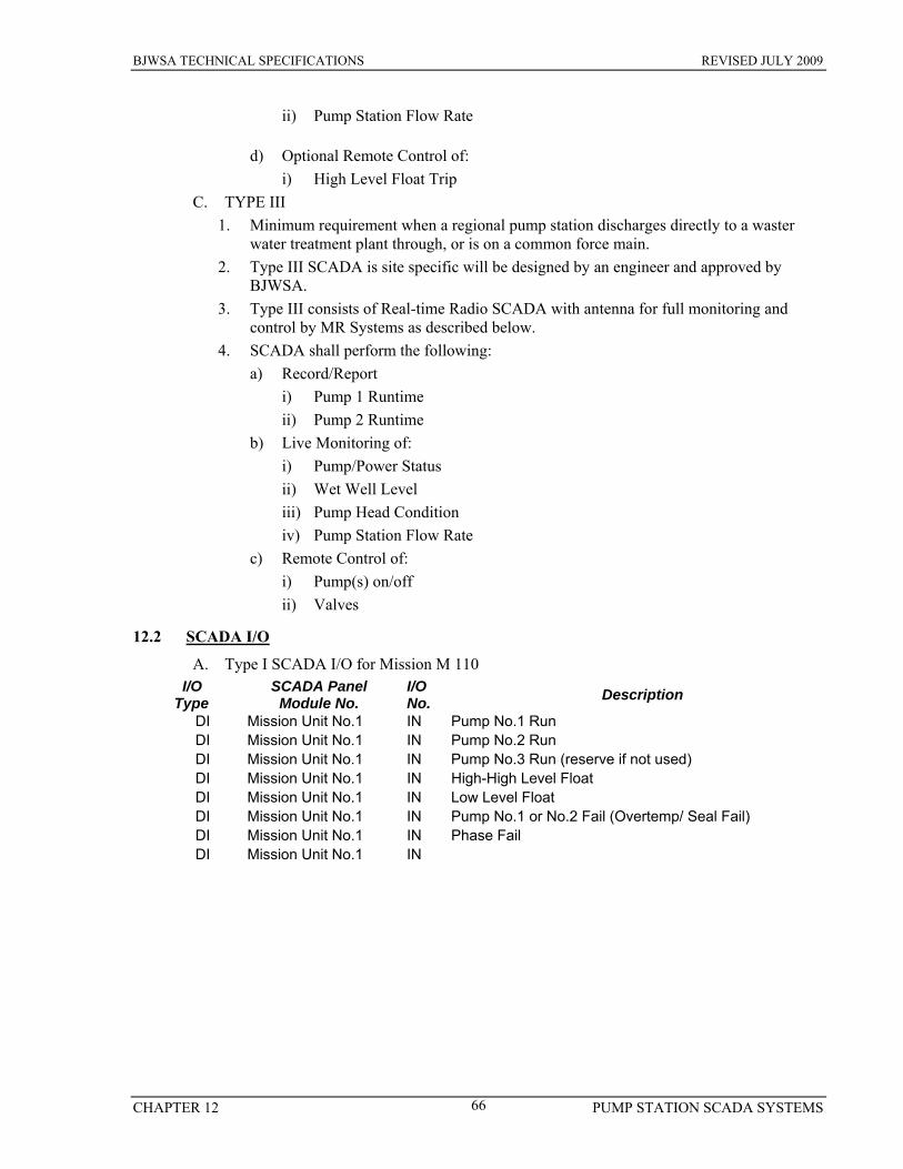
BJWSA TECHNICAL SPECIFICATIONS REVISED JULY 2009
CHAPTER 12 PUMP STATION SCADA SYSTEMS 66
ii) Pump Station Flow Rate
d) Optional Remote Control of: i) High Level Float Trip
C. TYPE III 1. Minimum requirement when a regional pump station discharges directly to a waster
water treatment plant through, or is on a common force main. 2. Type III SCADA is site specific will be designed by an engineer and approved by
BJWSA. 3. Type III consists of Real-time Radio SCADA with antenna for full monitoring and
control by MR Systems as described below. 4. SCADA shall perform the following:
a) Record/Report i) Pump 1 Runtime ii) Pump 2 Runtime
b) Live Monitoring of: i) Pump/Power Status ii) Wet Well Level iii) Pump Head Condition iv) Pump Station Flow Rate
c) Remote Control of: i) Pump(s) on/off ii) Valves
12.2 SCADA I/O
A. Type I SCADA I/O for Mission M 110 I/O Type
SCADA Panel Module No.
I/O No. Description
DI Mission Unit No.1 IN Pump No.1 Run DI Mission Unit No.1 IN Pump No.2 Run DI Mission Unit No.1 IN Pump No.3 Run (reserve if not used) DI Mission Unit No.1 IN High-High Level Float DI Mission Unit No.1 IN Low Level Float DI Mission Unit No.1 IN Pump No.1 or No.2 Fail (Overtemp/ Seal Fail) DI Mission Unit No.1 IN Phase Fail DI Mission Unit No.1 IN

BJWSA TECHNICAL SPECIFICATIONS REVISED JULY 2009
CHAPTER 12 PUMP STATION SCADA SYSTEMS 67
B. Type II SCADA I/O for Mission M 800
I/O Type
SCADA Panel Module No.
I/O No. Description
DI Mission Unit No.1 IN Pump No.1 Run DI Mission Unit No.1 IN Pump No.2 Run DI Mission Unit No.1 IN Pump No.3 Run (reserve if not used) DI Mission Unit No.1 IN High-High Level Float DI Mission Unit No.1 IN Low Level Float DI Mission Unit No.1 IN Pump No.1 or No.2 Fail (Overtemp/ *Seal Fail) DI Mission Unit No.1 IN Phase Fail DI Mission Unit No.1 IN Reserved for Back Up System** if Necessary DO Mission Unit No.1 OUT Pump Disable DO Mission Unit No.1 OUT Pump Remote Call-to-Run AI Mission Unit No.1 AI Wetwell Level AI Mission Unit No.1 AI Flow Meter
* Seal sensor will not be required for self priming stations. ** Back up system could be back up pumps or a back up generator. All SCADA systems will include the built in monitoring of AC fail, battery fail, and input wiring fault. Installation of SCADA conduits/cables adhere to control panel penetration restrictions addressed else where in this Specifications. Record Drawings: Communication/Control module used is to be included in Record Drawings along with AsB SCADA schematic.
END OF SECTION
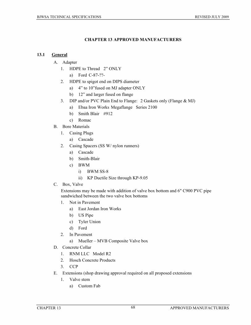
BJWSA TECHNICAL SPECIFICATIONS REVISED JULY 2009
CHAPTER 13 APPROVED MANUFACTURERS 68
CHAPTER 13 APPROVED MANUFACTURERS
13.1 General A. Adapter
1. HDPE to Thread 2” ONLY a) Ford C-87-??-
2. HDPE to spigot end on DIPS diameter a) 4” to 10”fused on MJ adapter ONLY b) 12” and larger fused on flange
3. DIP and/or PVC Plain End to Flange: 2 Gaskets only (Flange & MJ) a) Ebaa Iron Works Megaflange Series 2100 b) Smith Blair #912 c) Romac
B. Bore Materials 1. Casing Plugs
a) Cascade 2. Casing Spacers (SS W/ nylon runners)
a) Cascade b) Smith-Blair c) BWM
i) BWM SS-8 ii) KP Ductile Size through KP-9.05
C. Box, Valve Extensions may be made with addition of valve box bottom and 6" C900 PVC pipe sandwiched between the two valve box bottoms 1. Not in Pavement
a) East Jordan Iron Works b) US Pipe c) Tyler Union d) Ford
2. In Pavement a) Mueller – MVB Composite Valve box
D. Concrete Collar 1. RNM LLC Model R2 2. Hosch Concrete Products 3. CCP
E. Extensions (shop drawing approval required on all proposed extensions 1. Valve stem
a) Custom Fab

BJWSA TECHNICAL SPECIFICATIONS REVISED JULY 2009
CHAPTER 13 APPROVED MANUFACTURERS 69
13.1 General F. Flowmeters
1. Flowtube Sensors a) Rosemount 8700 Series
2. Transmitter a) Rosemount 8712
G. Hatches 1. Aluminum w/ recessed pad-lockable provision & hinged safety grate
a) Bilco b) USF Fabrication Inc. c) Halliday
H. Manhole 1. Gravity- w/Granite Stone, 5,000 PSI
a) Knight Precast b) Tindall Concrete c) Hanson Pipe Products d) Parker Precast
2. Manhole Steps a) M.A. Industries Inc. PSI-PF b) American Step Company, Inc. ML-10
3. Frame & Lid with BJWSA Logo a) East Jordan Iron Works V1327 b) US Foundry USF-195-E-ORS
4. Seal, Exterior (12”) a) Mar-Mac Manufacturing b) ConSeal c) Cretex
5. Vent a) Hanson Pipe Products
I. Markers 1. Urban 4” x 54”
a) RNM LLC b) Hosch Concrete Products
2. Rural 6” x 10’ in Concrete footing J. Restraint (Mechanical)
1. Restraint, Gland a) DIP
i) Ebaa Iron Works 1100 Series Megalug ii) Ford Series 1400 iii) Romac RomaGrip
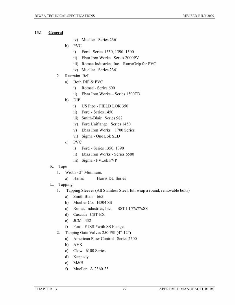
BJWSA TECHNICAL SPECIFICATIONS REVISED JULY 2009
CHAPTER 13 APPROVED MANUFACTURERS 70
13.1 General iv) Mueller Series 2361
b) PVC i) Ford Series 1350, 1390, 1500 ii) Ebaa Iron Works Series 2000PV iii) Romac Industries, Inc. RomaGrip for PVC iv) Mueller Series 2361
2. Restraint, Bell a) Both DIP & PVC
i) Romac - Series 600 ii) Ebaa Iron Works – Series 1500TD
b) DIP i) US Pipe - FIELD LOK 350 ii) Ford - Series 1450 iii) Smith-Blair Series 982 iv) Ford Uniflange Series 1450 v) Ebaa Iron Works 1700 Series vi) Sigma - One Lok SLD
c) PVC i) Ford - Series 1350, 1390 ii) Ebaa Iron Works - Series 6500 iii) Sigma - PVLok PVP
K. Tape 1. Width - 2” Minimum.
a) Harris Harris DU Series L. Tapping
1. Tapping Sleeves (All Stainless Steel, full wrap a round, removable bolts) a) Smith Blair 665 b) Mueller Co. H304 SS c) Romac Industries, Inc. SST III ??x??xSS d) Cascade CST-EX e) JCM 432 f) Ford FTSS-*with SS Flange
2. Tapping Gate Valves 250 PSI (4”-12”) a) American Flow Control Series 2500 b) AVK c) Clow 6100 Series d) Kennedy e) M&H f) Mueller A-2360-23

BJWSA TECHNICAL SPECIFICATIONS REVISED JULY 2009
CHAPTER 13 APPROVED MANUFACTURERS 71
13.1 General M. Valves – See Water and Sewer for use specific valves
1. Resilient Seat a) Gate (2”) w/ IPT
i) AVK ii) Clow Model 2369 iii) Mueller A-2360
N. Wire 1. Splice: Direct Bury
a) 3M DBR-6 2. Tracer
a) Bore (#8) b) General (#12)
i) Kris-Tech Wire Co.
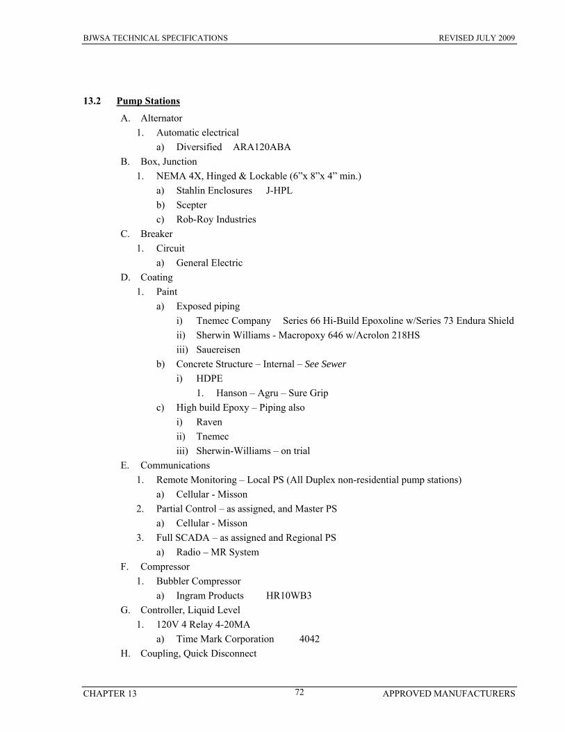
BJWSA TECHNICAL SPECIFICATIONS REVISED JULY 2009
CHAPTER 13 APPROVED MANUFACTURERS 72
13.2 Pump Stations A. Alternator
1. Automatic electrical a) Diversified ARA120ABA
B. Box, Junction 1. NEMA 4X, Hinged & Lockable (6”x 8”x 4” min.)
a) Stahlin Enclosures J-HPL b) Scepter c) Rob-Roy Industries
C. Breaker 1. Circuit
a) General Electric D. Coating
1. Paint a) Exposed piping
i) Tnemec Company Series 66 Hi-Build Epoxoline w/Series 73 Endura Shield ii) Sherwin Williams - Macropoxy 646 w/Acrolon 218HS iii) Sauereisen
b) Concrete Structure – Internal – See Sewer i) HDPE
1. Hanson – Agru – Sure Grip c) High build Epoxy – Piping also
i) Raven ii) Tnemec iii) Sherwin-Williams – on trial
E. Communications 1. Remote Monitoring – Local PS (All Duplex non-residential pump stations)
a) Cellular - Misson 2. Partial Control – as assigned, and Master PS
a) Cellular - Misson 3. Full SCADA – as assigned and Regional PS
a) Radio – MR System F. Compressor
1. Bubbler Compressor a) Ingram Products HR10WB3
G. Controller, Liquid Level 1. 120V 4 Relay 4-20MA
a) Time Mark Corporation 4042 H. Coupling, Quick Disconnect

BJWSA TECHNICAL SPECIFICATIONS REVISED JULY 2009
CHAPTER 13 APPROVED MANUFACTURERS 73
13.2 Pump Stations 1. Pressure Gauage
a) Universal Coupling (1”) male NPT, ½” female NPT, and Blank end i) Granger NPT ½” male (3LX91), NPT (1”) female (3LX90), Blank
(3LX85), and Nylon Lanyard (3LX84). 2. By-Pass
a) Bauer 4” i) Bauer # 105-0511 - Male NPT threaded end by socket
I. Disconnect – Electrical: NEMA 4x stainless steel enclosure. GE Main breaker shall have a lockable externally mounted control lever
1. Enclosure a) Hoffman
2. Breaker a) GE
J. Float 1. Weighted
a) RotoFloat K. Flowmeter
1. Air – 5 SCFH a) Dwyer Visi-Float VFA-3-BV
2. Liquid a) Rosemount
i) Meter/Transmitter 8712D ii) Flow Tube 8705 PTFE Teflon
L. Gauge (NOT generally required) 1. Stainless Steel, glycerin filled, with 4.5” dial in phenolic case
a) Ashcroft M. Hanger
1. Float a) Electric Specialty DORS -3
N. Horn 1. Alarm, external
a) Federal Signal 350, 115 VAC O. Pressure Transducer
1. 24VDC0-15PSI go a) Time Mark Corporation 450
P. Pumps 1. System
a) Self-priming i) Solids Handling
1. Gorman Rupp Co. Super T series

BJWSA TECHNICAL SPECIFICATIONS REVISED JULY 2009
CHAPTER 13 APPROVED MANUFACTURERS 74
13.2 Pump Stations b) Submersible
i) Grinder 1. ABS Piranha
ii) Solids Handling 1. ABS
2. Emergency Bypass a) Gorman Rupp b) Godwin
Q. Receptacle 1. Generator, (100 amp)(4) w/ Spring Door
a) Crouse-Hinds AR 1041 b) Appleton ADR1044
2. Generator, (200 amp)(4); door to have locking studs at 180 degrees at 3 & 9 o’clock a) Crouse-Hinds AR 2041 b) Appleton AR20044
R. Relay 1. Control, 3-pole blade w/
a) Allen Bradley 2. Phase
a) Sycom 102A 3. Phase Failure
a) Diversified SLA***ASA S. Starter
1. Motor a) General Electric
T. Surge Protection 1. Lightning surge
a) Innovative Technology PTX160 b) Joslyn
U. Surge Suppressor 1. Low voltage
a) Innovative Technology HS-120-10A V. Valve
1. Ball a) 1”, Stainless Steel Body
i) Matco-Norca Model 760 ii) FNW 200X iii) Merit Brass 800 WOG
b) 2”, Iron body

BJWSA TECHNICAL SPECIFICATIONS REVISED JULY 2009
CHAPTER 13 APPROVED MANUFACTURERS 75
13.2 Pump Stations i) Crane ii) Hammond 8433 iii) Inline 302F
2. Check Valve (Vault or above Ground) a) Swing (2” only)
i) Matco-Norca 115S ii) Legend Valve (Brass) T-451/S-451
b) Swing 4” and larger i) Golden Anderson ii) Flomatic Model 90LS iii) Clow F-5381 style 106SL
W. Wetwell 1. Structure Granite Stone, 5,000 PSI
a) Knight Precast b) Tindall Concrete c) Hanson Pipe Products d) Parker Precast
2. Vent (4.75 square SS or Aluminum Frame w/1/4x1x1 covered w/1x1x1 6” square grate) a) Hanson Pipe Products
13.3 Sewer A. Clean Out
1. Traffic or 6” a) US Foundry USF 7621
2. Non Traffic 4” a) Valve Box Tap w/ Sewer Lid
B. Coatings Structure Interior 1. HDPE
a) Hanson Agru Sure-Grip b) C.I.M. Industry Inc. CIM-2000 c) GSE Studliner
2. High build Epoxy a) Raven 405 b) Tnemec c) Sherwin-Williams – on trial d) Sauereisen
C. Fittings 1. PVC: SDR 26 Heavy wall
a) Multi Fittings
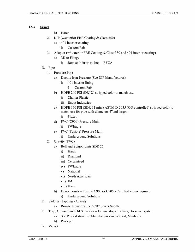
BJWSA TECHNICAL SPECIFICATIONS REVISED JULY 2009
CHAPTER 13 APPROVED MANUFACTURERS 76
13.3 Sewer b) Harco
2. DIP (w/exterior FBE Coating & Class 350) a) 401 interior coating
i) Custom Fab 3. Adapter (w/ exterior FBE Coating & Class 350 and 401 interior coating)
a) MJ to Flange i) Romac Industries, Inc. RFCA
D. Pipe 1. Pressure Pipe
a) Ductile Iron Pressure (See DIP Manufactures) i) 401 interior lining
1. Custom Fab b) HDPE 200 PSI (DR) 2” stripped color to match use.
i) Charter Plastic ii) Endot Industries
c) HDPE 160 PSI (SDR 11 min.) ASTM D-3035 (OD controlled) stripped color to match use for pipe with diameters 4”and larger i) Plexco
d) PVC (C909) Pressure Main i) PWEagle
e) PVC (Fusible) Pressure Main i) Underground Solutions
2. Gravity (PVC) a) Bell and Spigot joints SDR 26
i) Hawk ii) Diamond iii) Certainteed iv) PWEagle v) National vi) North American vii) JM viii) Harco
b) Fusion joints – Fusible C900 or C905 - Certified video required i) Underground Solutions
E. Saddles, Tapping - Gravity a) Romac Industries Inc. “CB” Sewer Saddle
F. Trap, Grease/Sand Oil Separator – Failure stops discharge to sewer system a) See Precast structure Manufactures in General, Manholes b) Proceptor
G. Valves
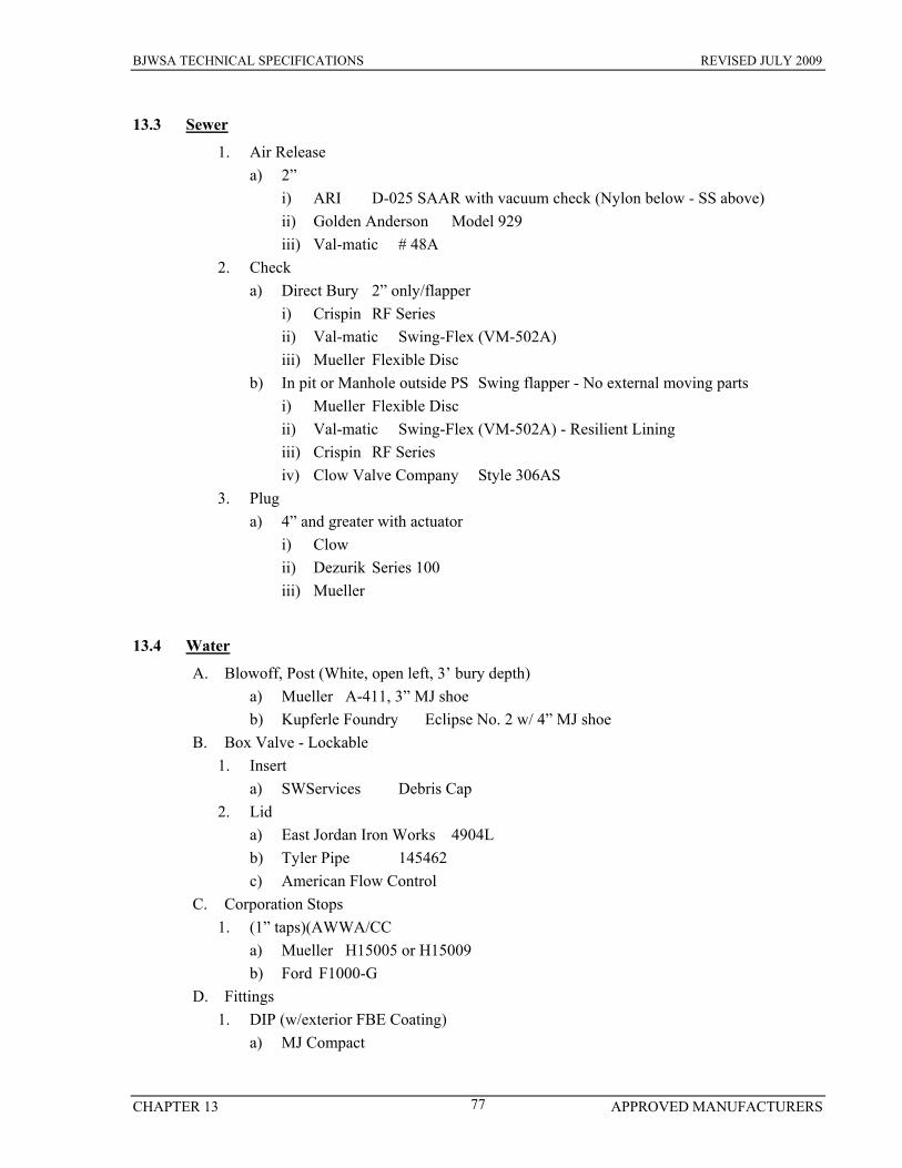
BJWSA TECHNICAL SPECIFICATIONS REVISED JULY 2009
CHAPTER 13 APPROVED MANUFACTURERS 77
13.3 Sewer 1. Air Release
a) 2” i) ARI D-025 SAAR with vacuum check (Nylon below - SS above) ii) Golden Anderson Model 929 iii) Val-matic # 48A
2. Check a) Direct Bury 2” only/flapper
i) Crispin RF Series ii) Val-matic Swing-Flex (VM-502A) iii) Mueller Flexible Disc
b) In pit or Manhole outside PS Swing flapper - No external moving parts i) Mueller Flexible Disc ii) Val-matic Swing-Flex (VM-502A) - Resilient Lining iii) Crispin RF Series iv) Clow Valve Company Style 306AS
3. Plug a) 4” and greater with actuator
i) Clow ii) Dezurik Series 100 iii) Mueller
13.4 Water A. Blowoff, Post (White, open left, 3’ bury depth)
a) Mueller A-411, 3” MJ shoe b) Kupferle Foundry Eclipse No. 2 w/ 4” MJ shoe
B. Box Valve - Lockable 1. Insert
a) SWServices Debris Cap 2. Lid
a) East Jordan Iron Works 4904L b) Tyler Pipe 145462 c) American Flow Control
C. Corporation Stops 1. (1” taps)(AWWA/CC
a) Mueller H15005 or H15009 b) Ford F1000-G
D. Fittings 1. DIP (w/exterior FBE Coating)
a) MJ Compact
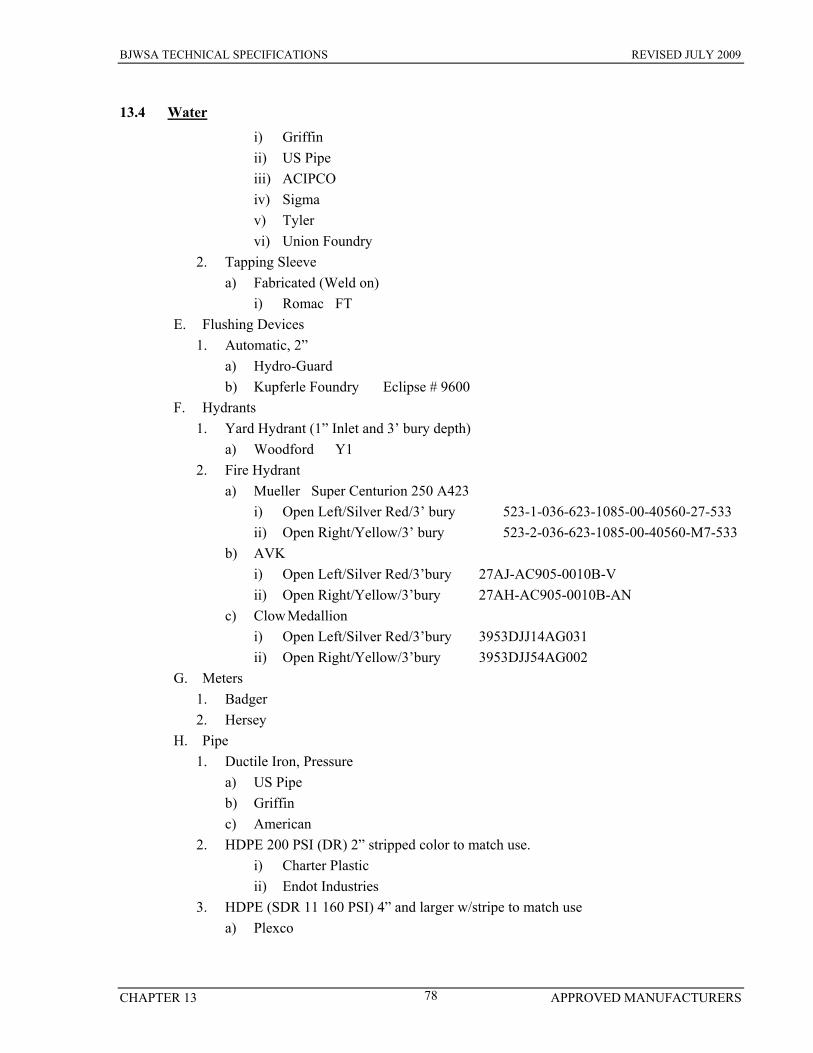
BJWSA TECHNICAL SPECIFICATIONS REVISED JULY 2009
CHAPTER 13 APPROVED MANUFACTURERS 78
13.4 Water i) Griffin ii) US Pipe iii) ACIPCO iv) Sigma v) Tyler vi) Union Foundry
2. Tapping Sleeve a) Fabricated (Weld on)
i) Romac FT E. Flushing Devices
1. Automatic, 2” a) Hydro-Guard b) Kupferle Foundry Eclipse # 9600
F. Hydrants 1. Yard Hydrant (1” Inlet and 3’ bury depth)
a) Woodford Y1 2. Fire Hydrant
a) Mueller Super Centurion 250 A423 i) Open Left/Silver Red/3’ bury 523-1-036-623-1085-00-40560-27-533 ii) Open Right/Yellow/3’ bury 523-2-036-623-1085-00-40560-M7-533
b) AVK i) Open Left/Silver Red/3’bury 27AJ-AC905-0010B-V ii) Open Right/Yellow/3’bury 27AH-AC905-0010B-AN
c) Clow Medallion i) Open Left/Silver Red/3’bury 3953DJJ14AG031 ii) Open Right/Yellow/3’bury 3953DJJ54AG002
G. Meters 1. Badger 2. Hersey
H. Pipe 1. Ductile Iron, Pressure
a) US Pipe b) Griffin c) American
2. HDPE 200 PSI (DR) 2” stripped color to match use. i) Charter Plastic ii) Endot Industries
3. HDPE (SDR 11 160 PSI) 4” and larger w/stripe to match use a) Plexco
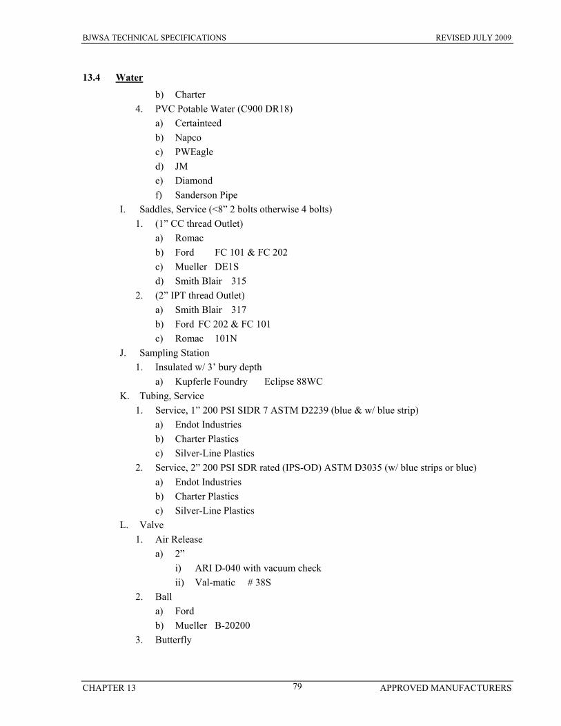
BJWSA TECHNICAL SPECIFICATIONS REVISED JULY 2009
CHAPTER 13 APPROVED MANUFACTURERS 79
13.4 Water b) Charter
4. PVC Potable Water (C900 DR18) a) Certainteed b) Napco c) PWEagle d) JM e) Diamond f) Sanderson Pipe
I. Saddles, Service (<8” 2 bolts otherwise 4 bolts) 1. (1” CC thread Outlet)
a) Romac b) Ford FC 101 & FC 202 c) Mueller DE1S d) Smith Blair 315
2. (2” IPT thread Outlet) a) Smith Blair 317 b) Ford FC 202 & FC 101 c) Romac 101N
J. Sampling Station 1. Insulated w/ 3’ bury depth
a) Kupferle Foundry Eclipse 88WC K. Tubing, Service
1. Service, 1” 200 PSI SIDR 7 ASTM D2239 (blue & w/ blue strip) a) Endot Industries b) Charter Plastics c) Silver-Line Plastics
2. Service, 2” 200 PSI SDR rated (IPS-OD) ASTM D3035 (w/ blue strips or blue) a) Endot Industries b) Charter Plastics c) Silver-Line Plastics
L. Valve 1. Air Release
a) 2” i) ARI D-040 with vacuum check ii) Val-matic # 38S
2. Ball a) Ford b) Mueller B-20200
3. Butterfly

BJWSA TECHNICAL SPECIFICATIONS REVISED JULY 2009
CHAPTER 13 APPROVED MANUFACTURERS 80
13.4 Water a) 14” and larger
i) Pratt ii) Clow Series 4500 iii) Mueller Lineseal III 3211 iv) Dezurik AWWA C504
4. Check a) Rubber disk facing
i) Golden Anderson (HDL ASA 125) ii) Flomatic iii) Val-matic iv) Mueller A-2602-6-02 (Flange)
5. Gate 250 PSI (4” - 12”) i) American Flow Control Series 500 ii) AVK iii) Clow 6100 Series iv) Kennedy v) M&H 4067 vi) Mueller A-2360-23
END OF SECTION

BJWSA TECHNICAL SPECIFICATIONS REVISED JULY 2009
APPENDIX GENERAL DETAILS A
APPENDIX A – GENERAL STANDARD DETAIL DRAWINGS
DRAWING NUMBER TITLE G-01 Air Release Valve G-02 Bedding Detail – Pressure Pipe G-03 Bore and Jack Detail G-04 Bridge Attachment – Typical G-05 Bridge Attachment – Detail G-06 Piling Pipeline Support G-07 Curb Marking Detail G-08 Restraint - Mechanical G-09 Restraint – Thrust Blocking G-10 Typical Service Tie-in G-11 Submerged Crossings G-12 Standard Valve Detail G-13 Tapping Sleeve & Valve Detail G-14 2” Connection G-15 Tee and Valves
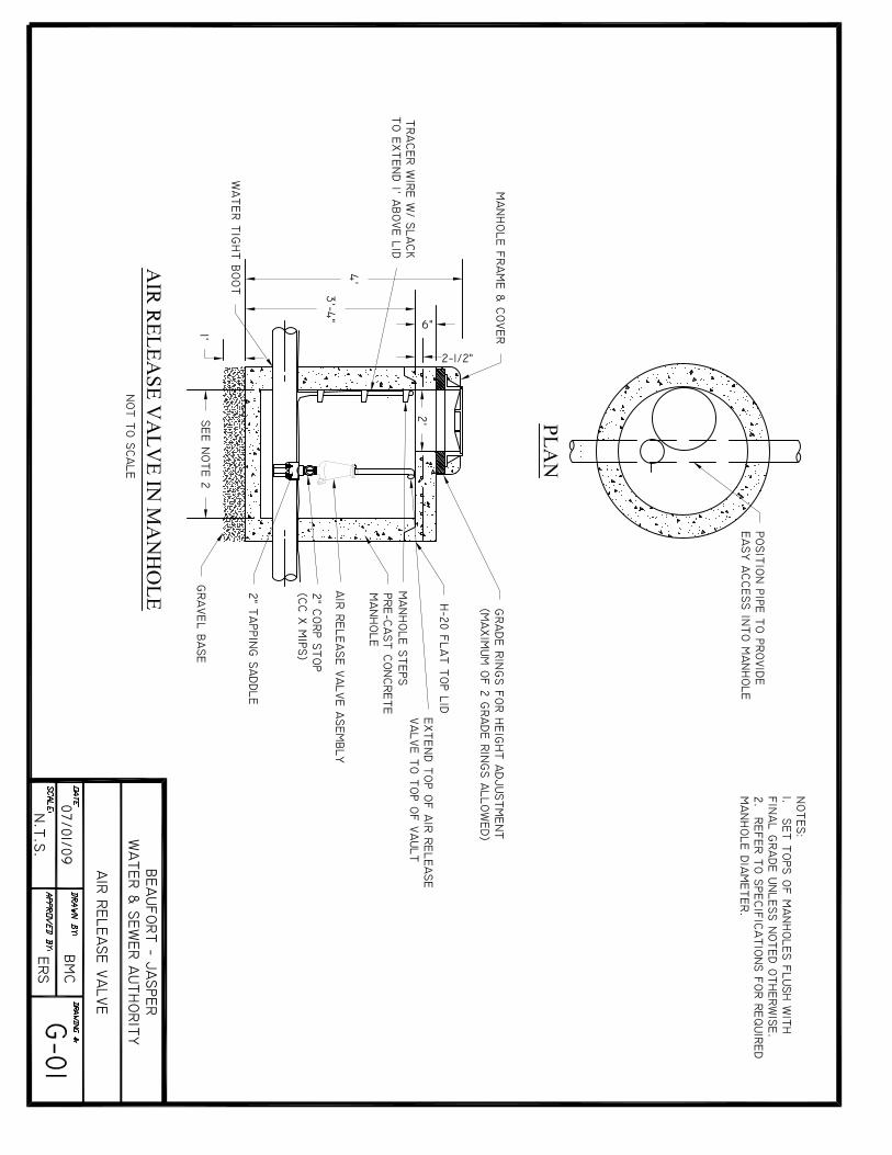
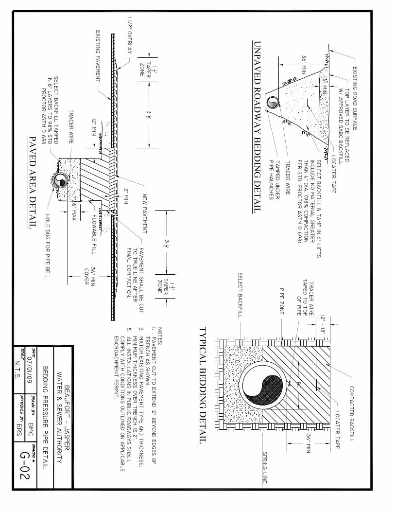
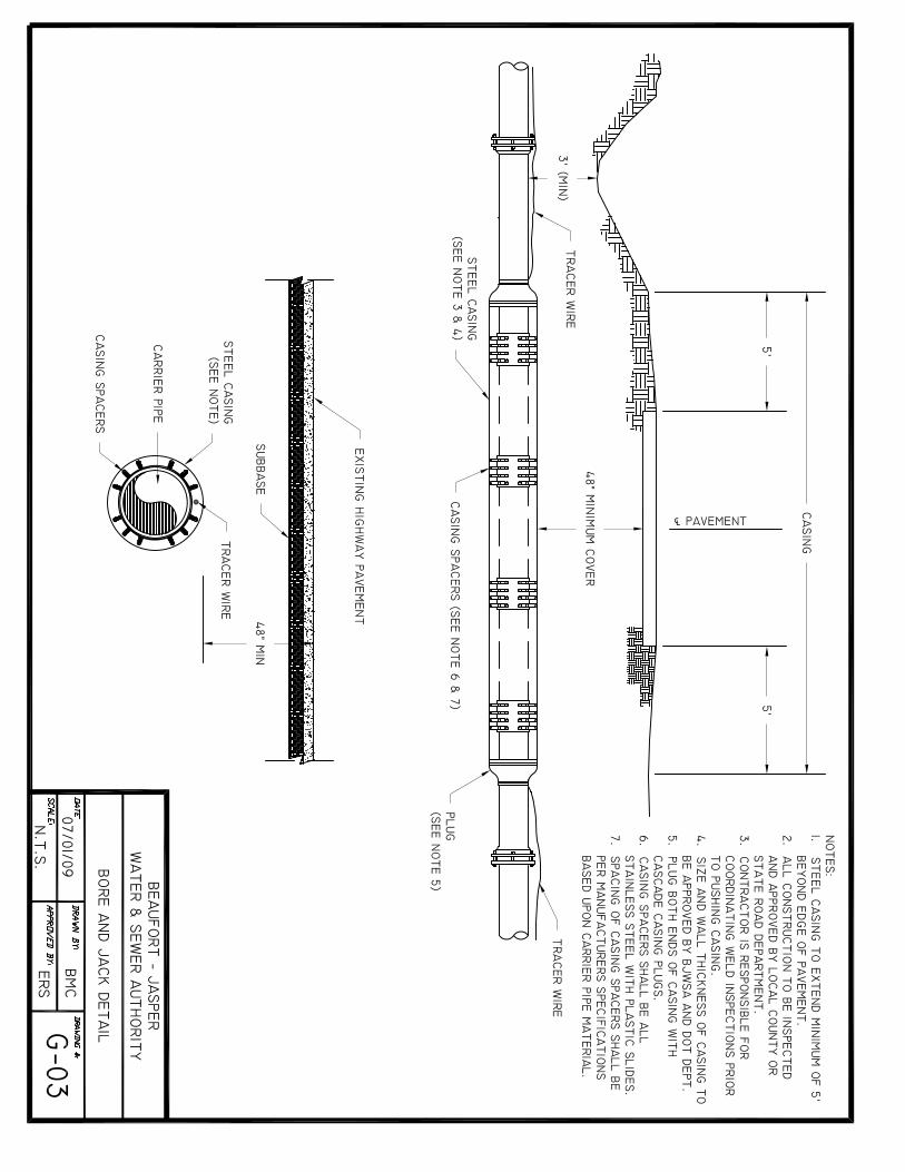
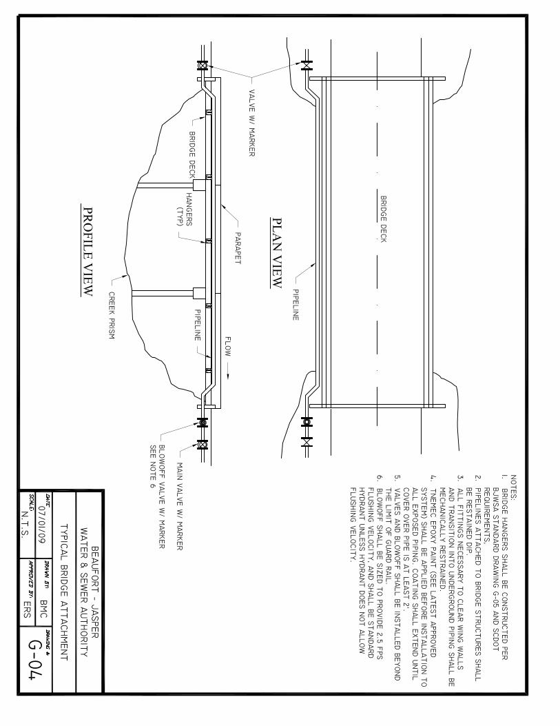

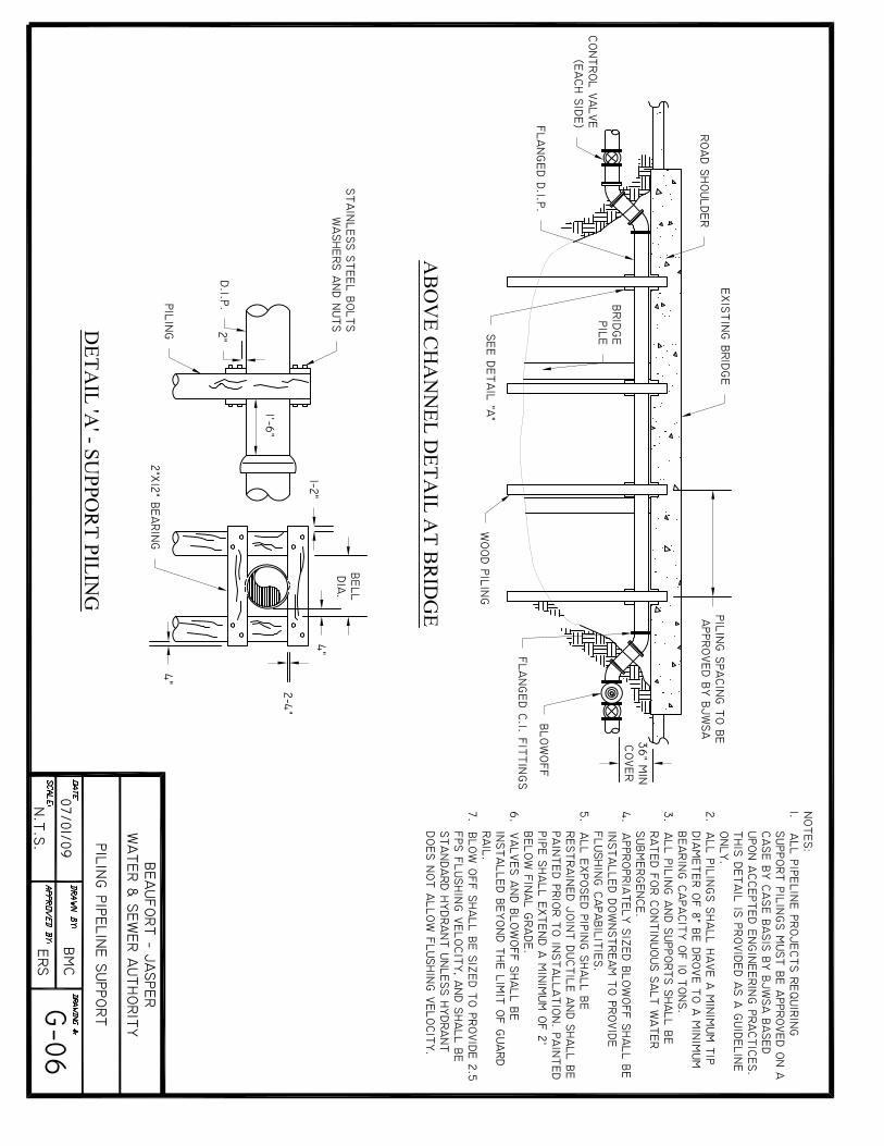


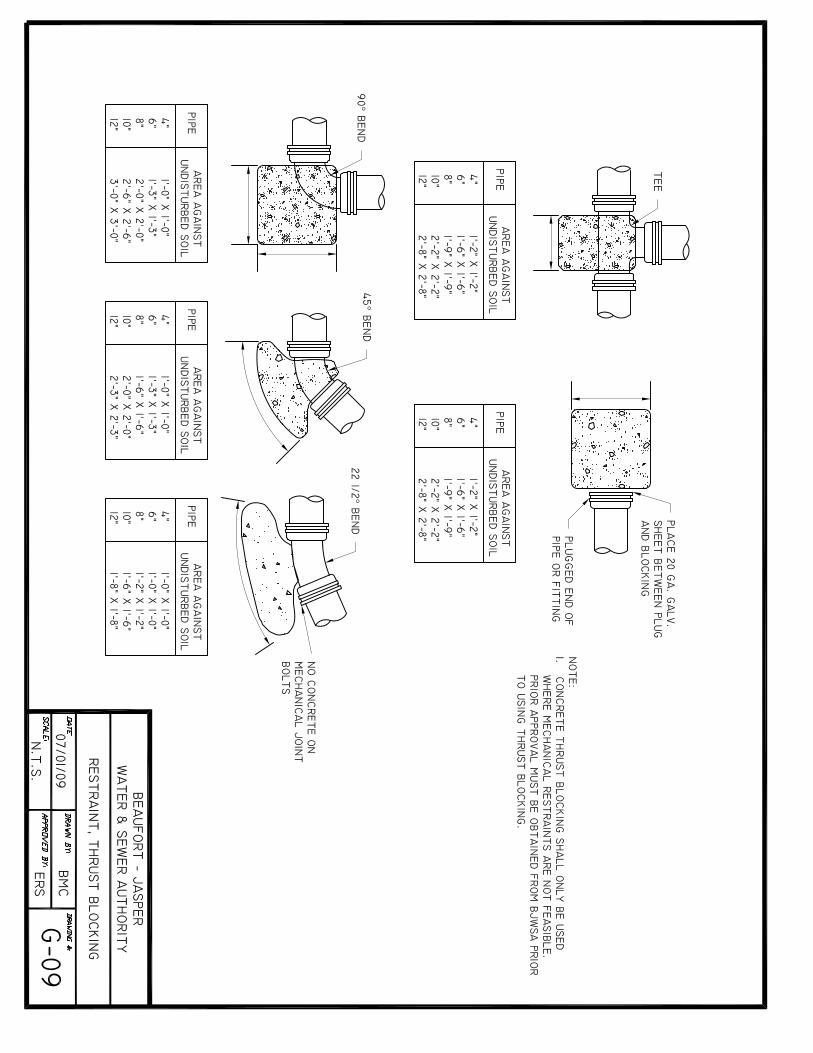

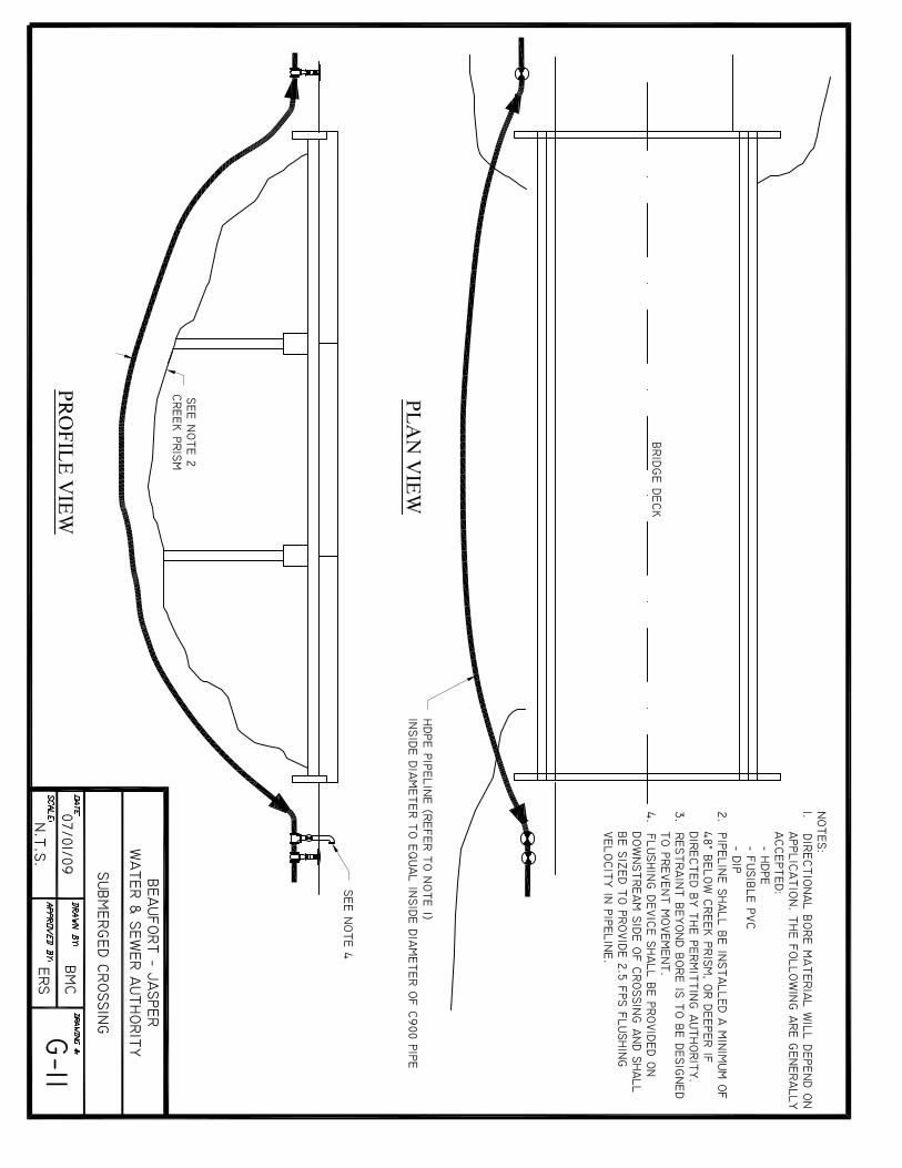


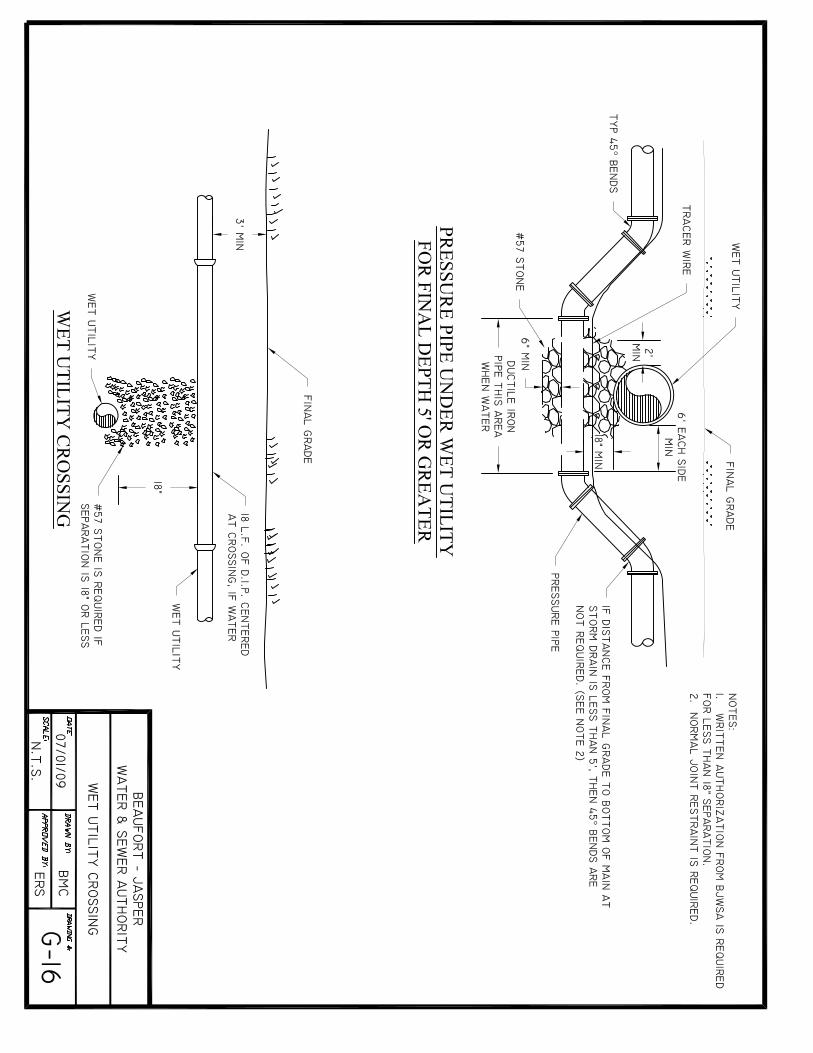

BJWSA TECHNICAL SPECIFICATIONS REVISED JULY 2009
APPENDIX WASTEWATER/SEWER STANDARD DETAILS
B
APPENDIX B – WASTEWATER/SEWER STANDARD DETAIL DRAWINGS
DRAWING NUMBER TITLE
S-01 Bedding Detail – Gravity Pipe S-02 Force Main Crossing S-03 Gravity Main Crossing S-04 Grease Trap Detail S-05 Manhole – Cover and Frame S-06 Manhole - Drop S-07 Manhole – Flat Top S-08 Manhole – Force Main Control S-09 Manhole - Standard S-10 Sewer Service Double S-11 Sewer Service - Single S-12 Pump Station Site Plan S-13A Pump Station Section I S-13B Pump Station Section II S-14 Pump Station Wet Well Detail S-15 Pump Station Fencing Detail S-16 Pump Station Electrical Layout S-17 Pump Station Control Panel & Main Disconnect S-18 Pump Station Bubbler S-19 Pump Station Hatch Detail S-20A Pump Station 2” Duplex Grinder, Plan S-20B Pump Station 2” Duplex Grinder, Section S-21 Pump Station Residential Control Panel S-22 Pump Station, Simplex Grinder S-23A Pump Station (Above Ground – 6x6), Site Plan S-23B Pump Station (Above Ground – 6x6), Detail #1 S-23C Pump Station (Above Ground – 6x6), Detail #2 S-23D Pump Station (Above Ground – 6x6), Detail #3 S-24 Sewer Check Valve S-25 Sewer Air Release Pedestal Assembly S-26 Duplex Residential Grinder Layout S-27 Pump Station Residential Duplex Control Panel S-28 Pump Station 6x6 Grate Detail
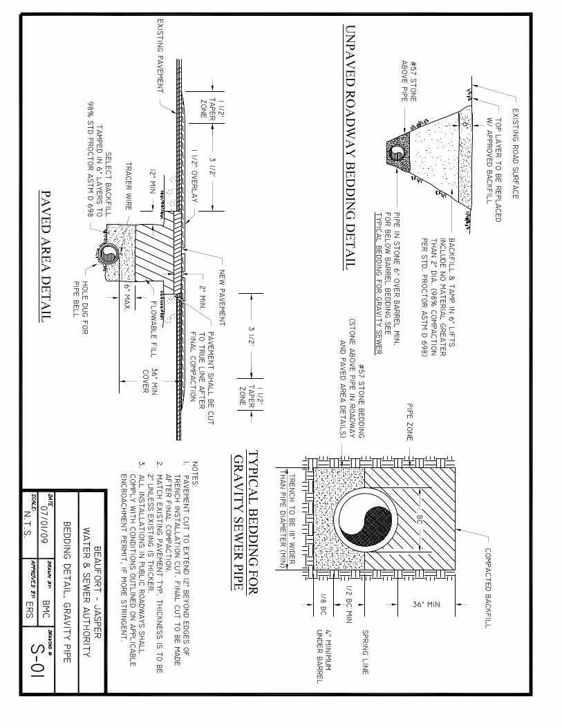

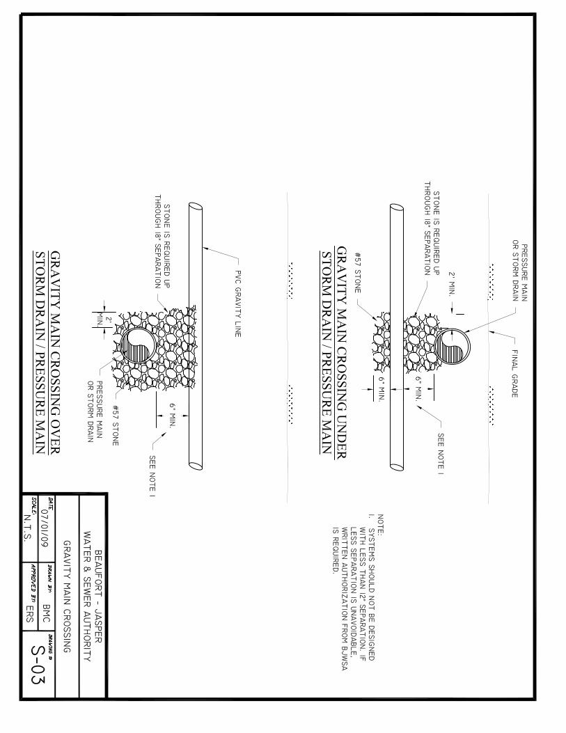
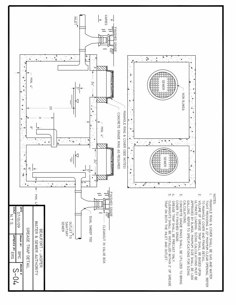
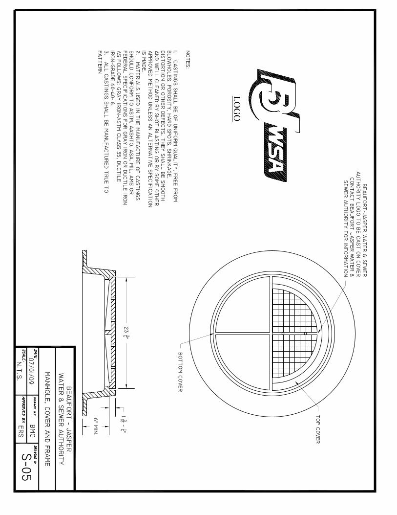
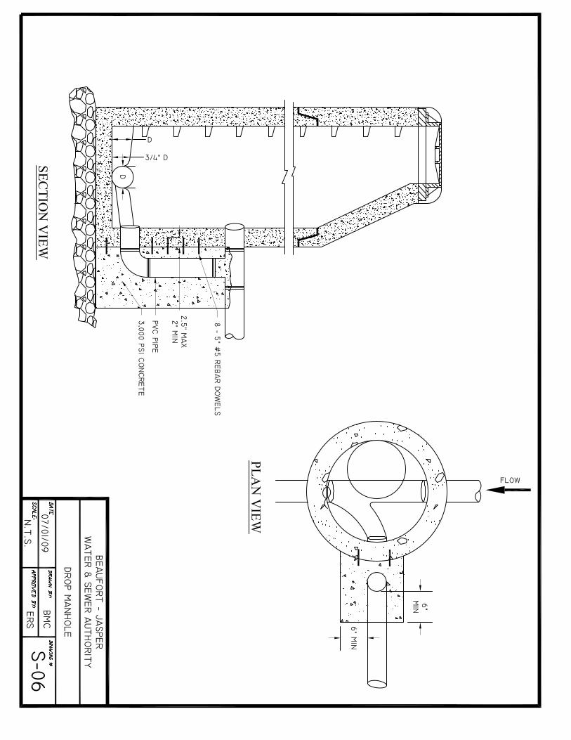
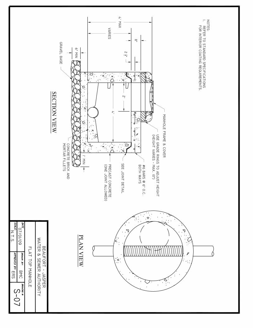
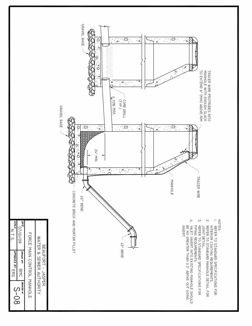

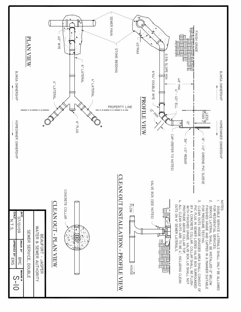
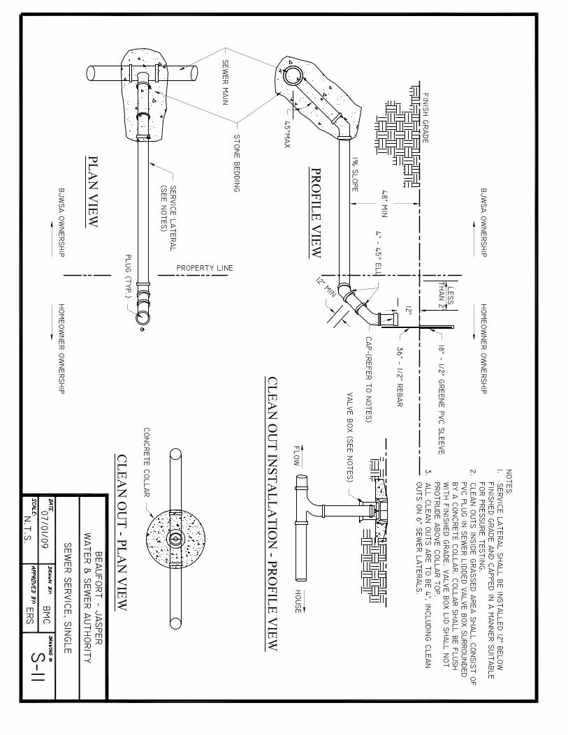
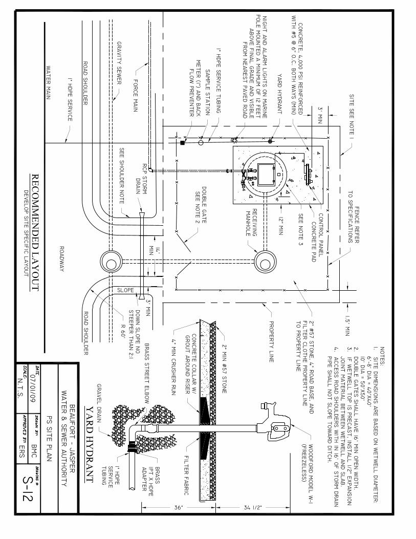
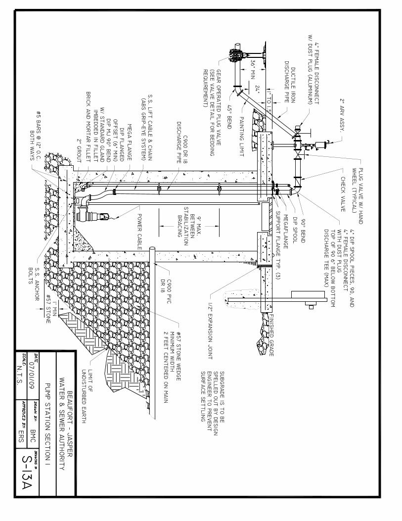
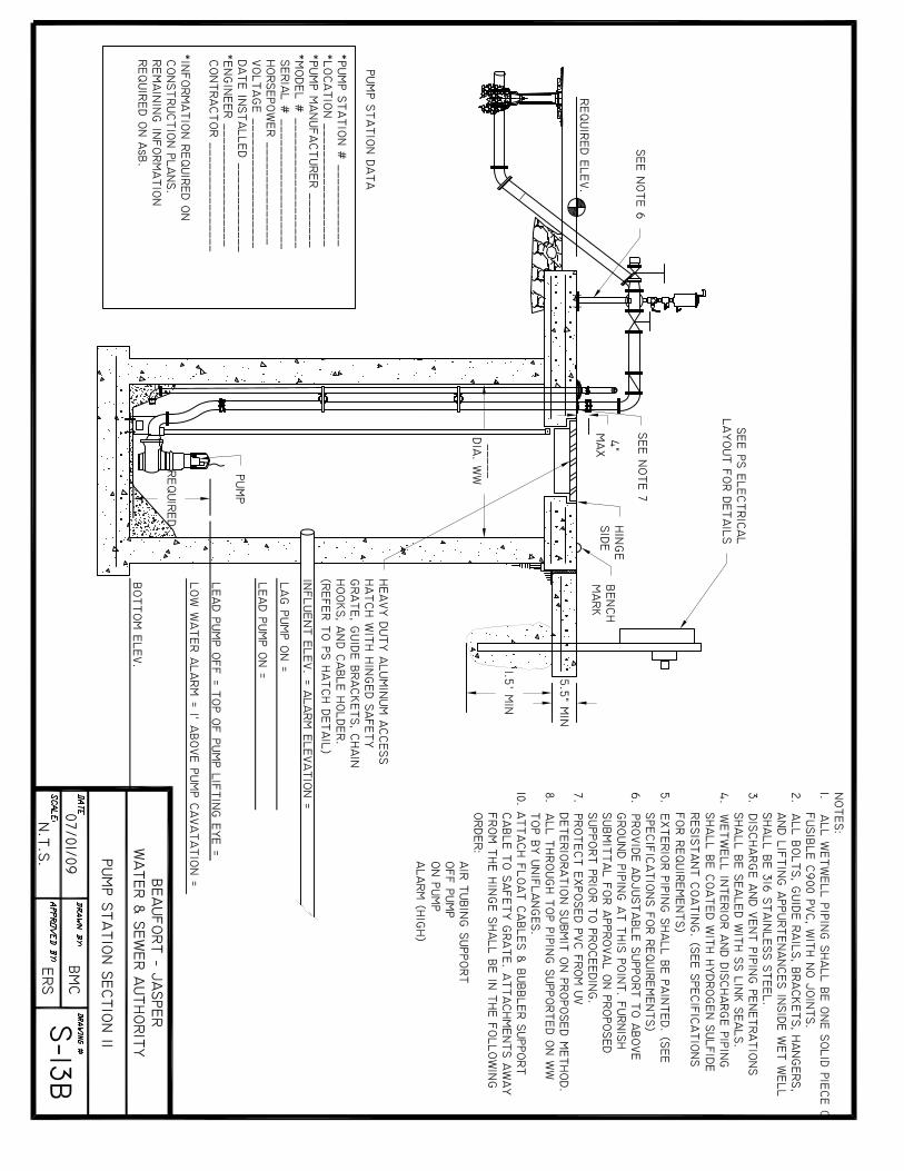
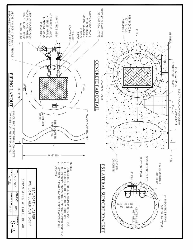


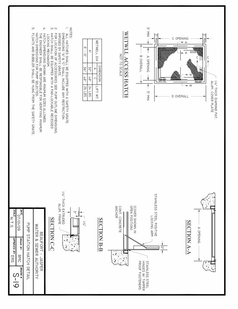

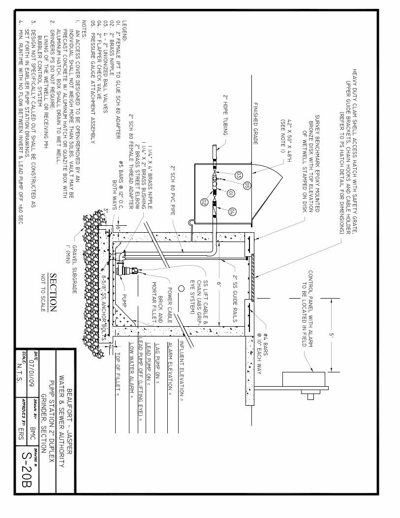
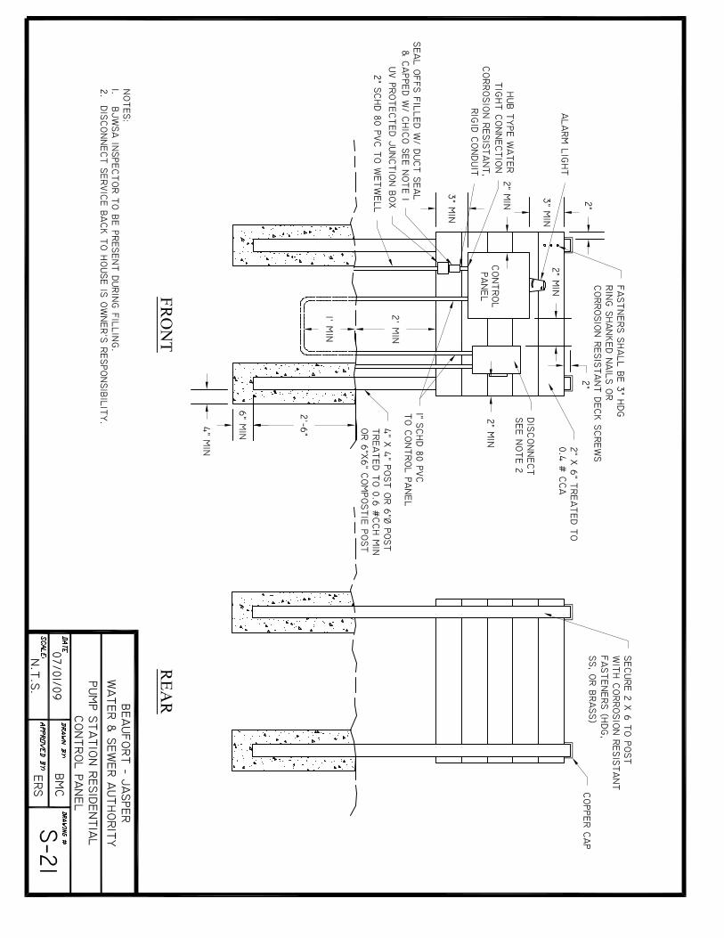
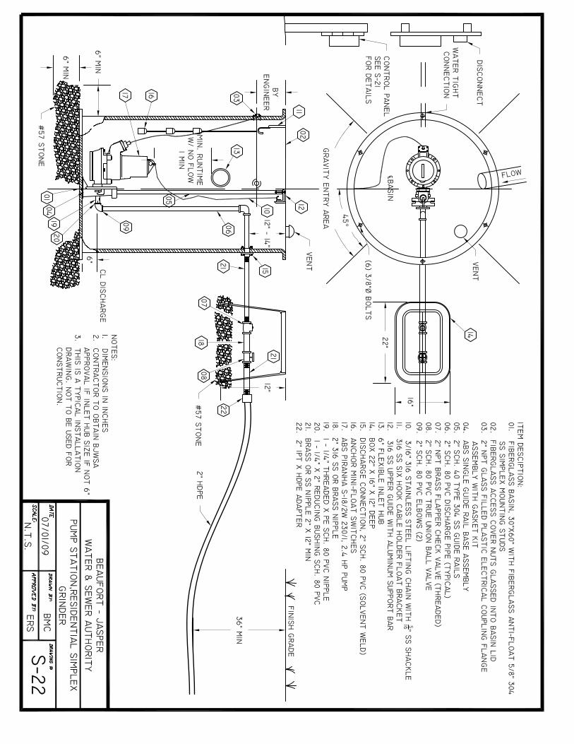
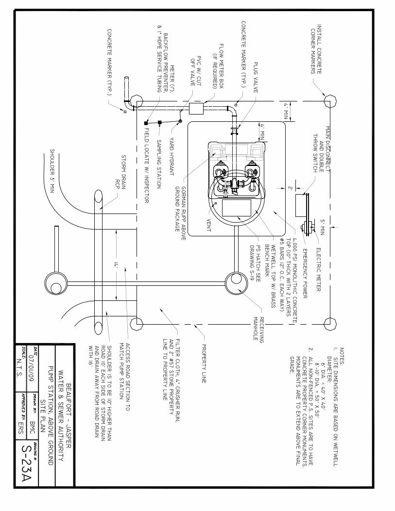


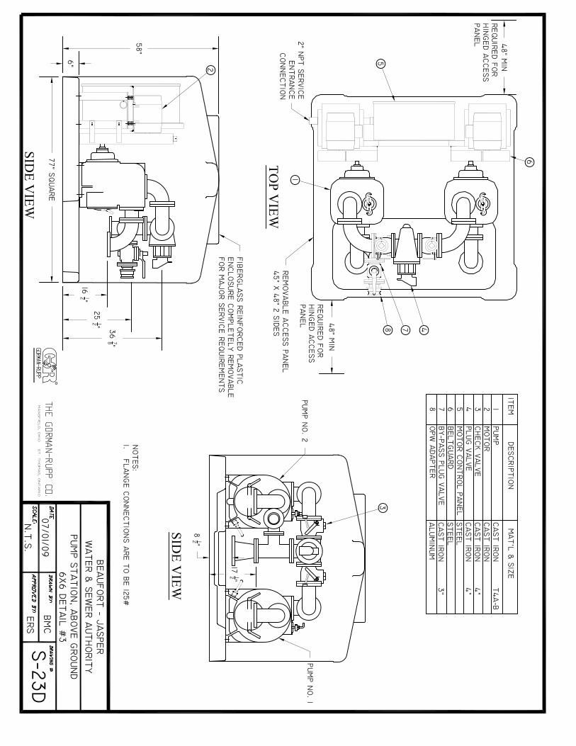

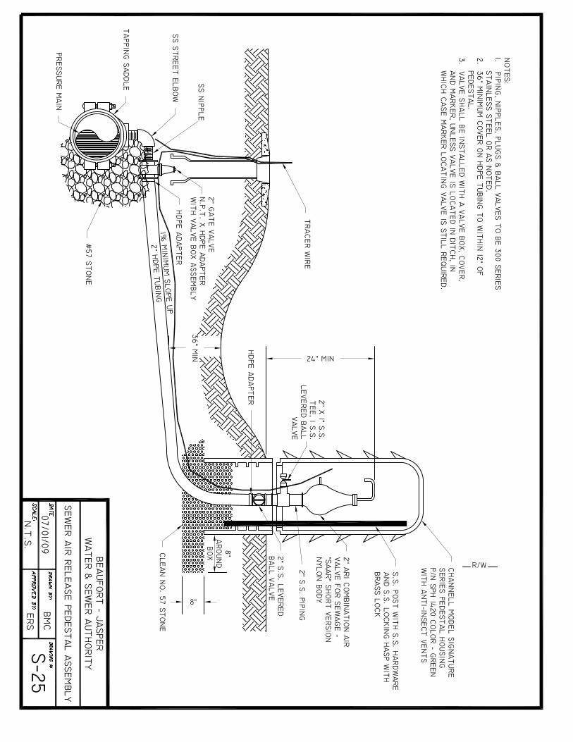

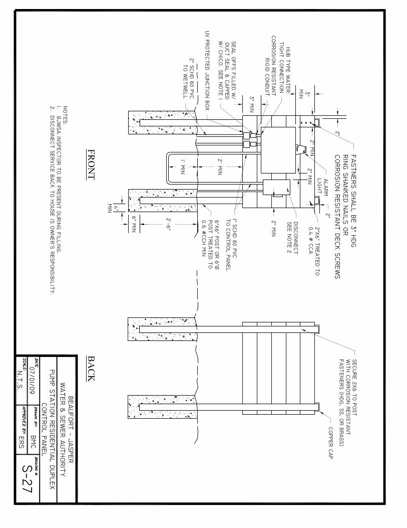
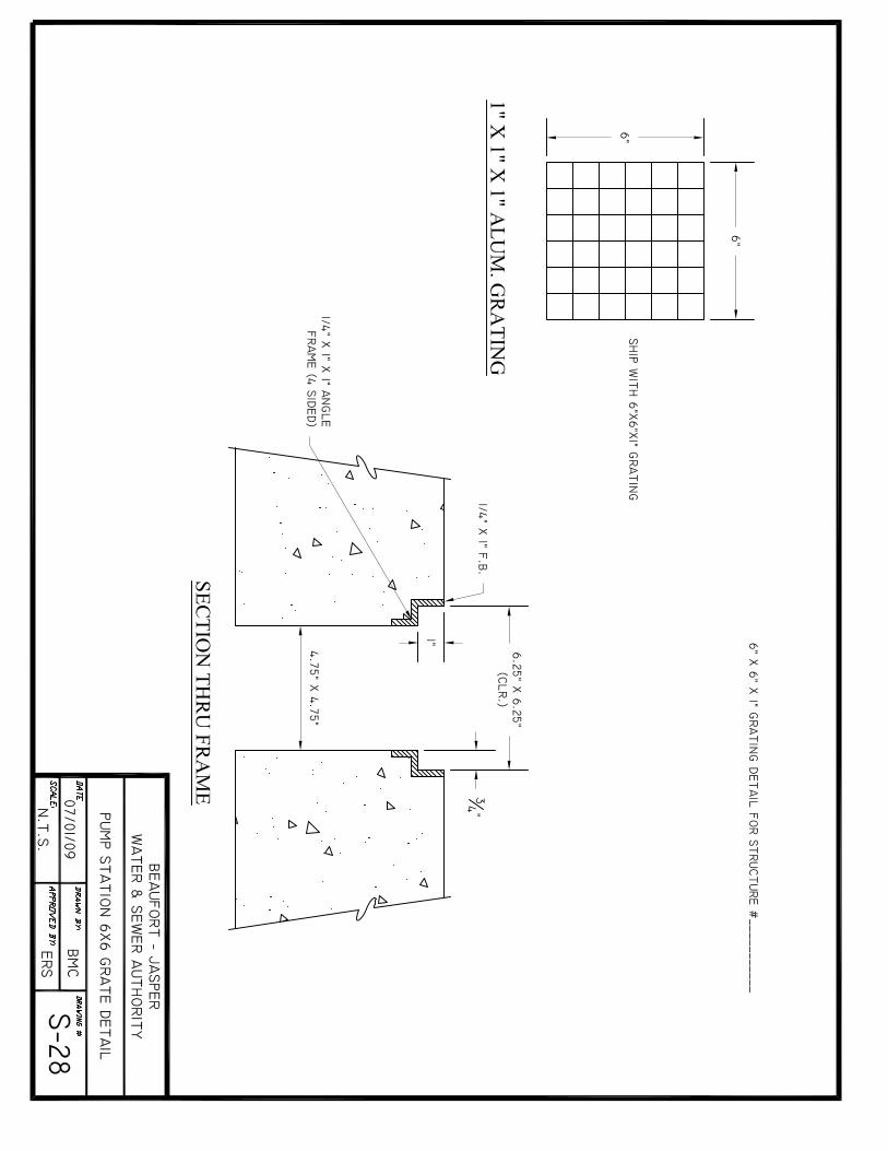
BJWSA TECHNICAL SPECIFICATIONS REVISED JULY 2009
APPENDIX WASTEWATER/SEWER STANDARD DETAILS
C
APPENDIX C – WATER STANDARD DETAIL DRAWINGS
DRAWING NUMBER TITLE
W-01 Backflow Prevention Detail W-02 Blow-off Hydrant Detail W-03 Fire Hydrant - Standard W-04 Fire Hydrant Detail – Under Ditch W-05 Jumper Connection Ditch W-06 Meter Vault Detail - Large W-07 Water Line Crossing Detail W-08 Water Service – Plan View W-09 Water Service Profile W-10 Water Sampling Station W-11 Meter Bank Detail; 6 Meter Max

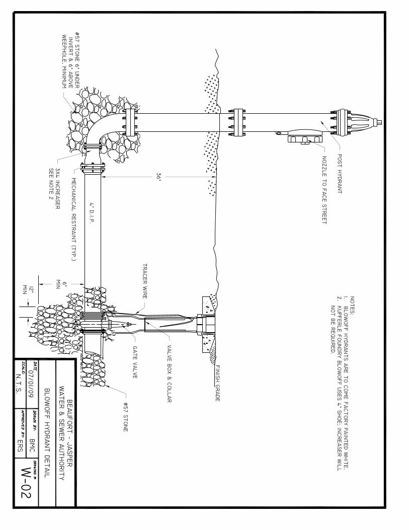

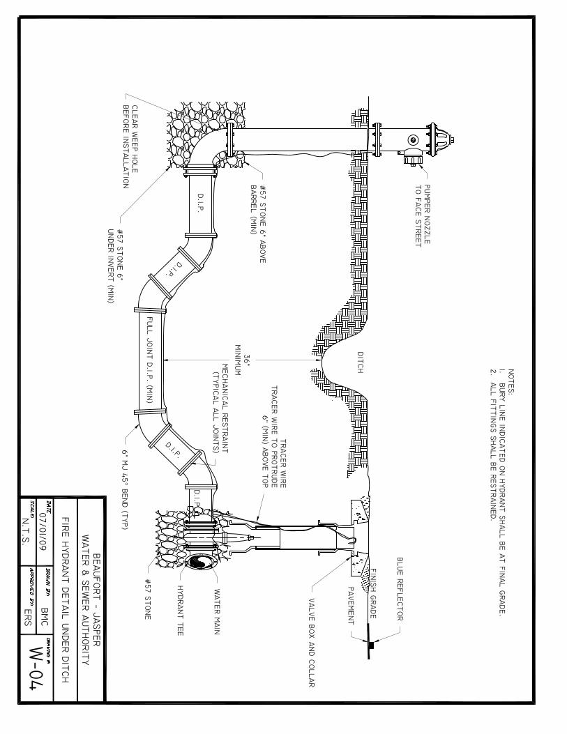
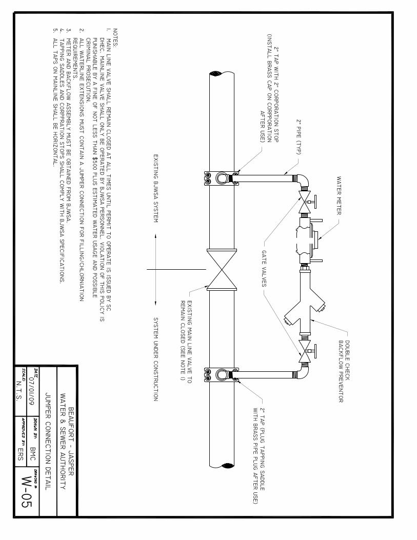
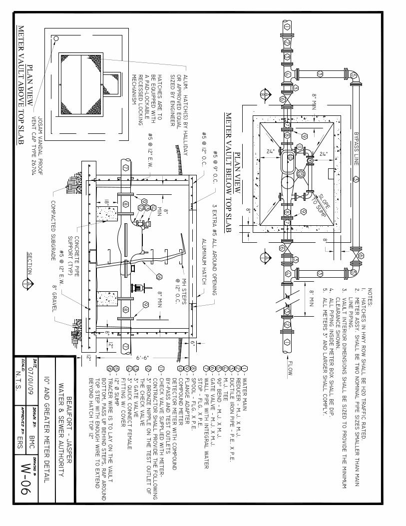
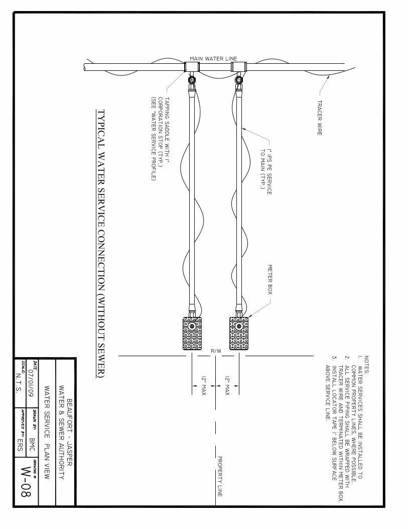
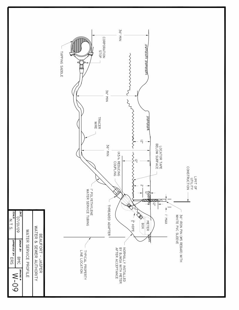
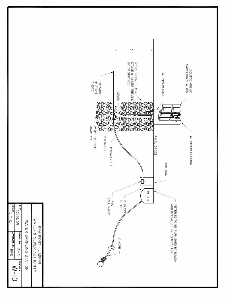


03100 - 1
SECTION 03100
CONCRETE FORMWORK
PART 1 - GENERAL
1.1 SUMMARY A. This Section specifies formwork for cast-in-place concrete. Contractor assumes all
responsibility for the design and engineering of the formwork as well as its construction and removal.
B. Related Sections: The following Sections contain requirements that relate to this Section:
1. Division 3 Section “Concrete Reinforcement” 2. Division 3 Section "Structural Cast-in-Place Concrete”
1.2 QUALITY ASSURANCE
A. Codes and Standards: Comply with provisions of the following codes, specifications, and standards, except where more stringent requirements are shown or specified:
1. Design Formwork for the loads, lateral pressure, and allowable stresses outlined in
Chapter 1, “Guide to Formwork for Concrete” ACI 347. PART 2 - PRODUCTS 2.1 FORM MATERIALS
A. Forms for Exposed Finish Concrete: Plywood, metal, metal-framed plywood faced, or other acceptable panel-type materials to provide continuous, straight, smooth, exposed surfaces. Furnish in largest practicable sizes to minimize number of joints and to conform to joint system shown on drawings.
B. Forms for Unexposed Finish Concrete: Plywood, lumber, metal, or another acceptable
material. Provide lumber dressed on at least two edges and one side for tight fit.
03100 - 2
PART 3 - EXECUTION 3.1 GENERAL
A. Coordinate the installation of joint materials, vapor retarder/barrier, and other related materials with placement of forms and reinforcing steel.
3.2 FORMS
A. General: Design, erect, support, brace, and maintain formwork to support vertical, lateral, static, and dynamic loads that might be applied until concrete structure can support such loads. Construct formwork so concrete members and structures are of correct size, shape, alignment, elevation, and position. Maintain formwork construction tolerances and surface irregularities complying with the following ACI 347 limits:
1. Provide Class A tolerances for all exposed concrete surfaces. Provide Class C for
non-exposed surfaces.
B. Construct forms to sizes, shapes, lines, and dimensions shown and to obtain accurate alignment, location, grades, level, and plumb work in finished structures. Provide for openings, offsets, sinkages, keyways, recesses, moldings, rustications, reglets, chamfers, blocking, screeds, bulkheads, anchorages and inserts, and other features required in the Work. Use selected materials to obtain required finishes. Solidly butt joints and provide backup at joints to prevent cement paste from leaking.
C. Fabricate forms for easy removal without hammering or prying against concrete surfaces.
Provide crush plates or wrecking plates where stripping may damage cast concrete surfaces. Provide top forms for inclined surfaces where slope is too steep to place concrete with bottom forms only. Kerf wood inserts for forming keyways, reglets, recesses, and the like for easy removal.
D. Provide temporary openings for clean-outs and inspections where interior area of formwork
is inaccessible before and during concrete placement. Securely brace temporary openings and set tightly to forms to prevent losing concrete mortar. Locate temporary openings in forms at inconspicuous locations.
E. Chamfer exposed corners and edges as indicated, using wood, metal, PVC, or rubber chamfer
strips fabricated to produce uniform smooth lines and tight edge joints.
F. Provisions for Other Trades: Provide openings in concrete formwork to accommodate work of other trades. Determine size and location of openings, recesses, and chases from trades providing such items. Accurately place and securely support items built into forms.

03100 - 3
G. Cleaning and Tightening: Thoroughly clean forms and adjacent surfaces to receive concrete. Remove chips, wood, sawdust, dirt, or other debris just before placing concrete. Retighten forms and bracing before placing concrete, as required, to prevent mortar leaks and maintain proper alignment.
H. Construct Formwork so that concrete surfaces will conform to the tolerance limits specified
in Table 4.3.1, “Tolerances for Formed Surfaces” ACI 301.
I. Provide positive means of adjustment (wedges or jacks) of shores and to compensate for anticipated deflections and settlement in the Formwork during concrete placing operations
J. Form Coating shall be a field applied chemical concrete release agent capable of preventing
bond between poured concrete and the form and shall contain no oil, or shall be a factory applied non-absorptive liner. Coat form before reinforcement is placed.
3.3 PREPARING FORM SURFACES
A. General: Coat contact surfaces of forms with an approved, nonresidual, low-VOC, form-coating compound before placing reinforcement.
B. Do not allow excess form-coating material to accumulate in forms or come into contact with
in-place concrete surfaces against which fresh concrete will be placed. Apply according to manufacturer's instructions.
1. Coat steel forms (if any) with a nonstaining, rust-preventative material. Rust-stained
steel formwork is not acceptable. 3.4 INSTALLING EMBEDDED ITEMS
A. General: Set and build into formwork anchorage devices and other embedded items required for other work that is attached to or supported by cast-in-place concrete. Use setting drawings, diagrams, instructions, and directions provided by suppliers of items to be attached.
B. Forms for Slabs: Set edge forms, bulkheads, and intermediate screed strips for slabs to
achieve required elevations and contours in finished surfaces. Provide and secure units to support screed strips using strike-off templates or compacting-type screeds.
3.5 REMOVING FORMS
A. Formwork not supporting weight of concrete, such as sides of beams, walls, columns, and similar parts of the work and not support other horizontal green concrete such as beams, floors, and similar parts of work, may be removed based on the following:
03100 - 4
a. Concrete compressive strength has reached 40% of design compressive strength, provided concrete is sufficiently hard to not be damaged by form-removal operations, and provided curing and protection operations are maintained. New loads shall not be placed on the concrete until the concrete compressive strength is 70% of the concrete design compressive strength.
B. Formwork supporting weight of green concrete, such as floors, beams and concrete
supporting green concrete such as columns and walls shall not be removed till concrete compressive strength reaches 70% of concrete design compressive strength, provided concrete is sufficiently hard to not be damaged by form-removal operations, and provided curing and protection operations are maintained.
C. Concrete test cylinders used to determine concrete compressive strength for the removal of
forms are extra cylinders beyond any cylinders required by any other project specifications. These cylinders and testing are at the contractor’s expense.
D. Reshoring of new concrete, see Section 3.8 RESHORING.
E. Form-facing material may be removed 4 days after placement only if shores and other
vertical supports have been arranged to permit removal of form-facing material without loosening or disturbing shores and supports.
3.6 REUSING FORMS
A. Clean and repair surfaces of forms to be reused in the Work. Split, frayed, delaminated, or otherwise damaged form-facing material will not be acceptable for exposed surfaces. Apply new form-coating compound as specified for new formwork.
B. When forms are extended for successive concrete placement, thoroughly clean surfaces,
remove fins and laitance, and tighten forms to close joints. Align and secure joint to avoid offsets. Do not use patched forms for exposed concrete surfaces except as acceptable to Engineer.
C. Form Ties shall be broken back at 1-inch from surface of concrete. Tie Cones, 1-inch
diameter by 1-inch long, shall be used on all exposed concrete. 3.7 CAMBER OF FORMS A. Camber slabs at midspan in increments of 1/8-inch per 10-foot of span and at end of
cantilevers in increments of 1/8-inch per 5-foot of span unless indicated otherwise on PLANS.
B. Do not camber beams unless indicated on PLANS.
03100 - 5
3.8 RESHORING
A. Reshore new construction until concrete being supported has reached the specified 28-day strength.
B. Place no live load on new construction while reshoring.
C. Complete reshoring as soon as practicable after stripping operations but not later than the end of
the working day on which stripping occurs.
D. Reshore so as to distribute construction loads safely to the ground or over sufficient number of levels in such a manner that the design LIVE LOAD of the levels supporting shores is not exceeded. Refer to GENERAL NOTES for design LIVE LOAD capacities.
E. Contractor shall design the reshoring procedure. The reshoring shall be designed not to damage the
both existing and new structures, maintain construction schedule, and protect the safety of the workers. The contractor shall be solely responsible for shoring and reshoring.
END OF SECTION 03100

03200 - 1
SECTION 03200
CONCRETE REINFORCEMENT PART 1 - GENERAL 1.1 SUMMARY
A. This Section specifies concrete reinforcing, including all materials, labor, equipment and services necessary to complete work.
B. Related Sections: The following Sections contain requirements that relate to this
Section: 1. Division 2 Section "Portland Cement Concrete Paving" 2. Division 3 Section “Structural Cast-in-Place Concrete” 3. Division 3 Section “Concrete Formwork” 1.2 SUBMITTALS
A. General: Submit each item in this Article according to the Conditions of the Contract
and Division 1 Specification Sections including number of sets. Sets in excess of the number indicated in the General Conditions will be discarded. One set will be retained by the structural department and the remaining sets will be returned to the Architect.
1. All submittals should be produced in a digital PDF format. Submittals will be
checked and any comments will be added to the digital PDF file. The PDF file, with any comments, will be returned to the contractor.
2. The contractor is responsible to check all submittals for accuracy and coordination with other trade. This check is required to be performed by the contractor prior to making any submittals to the architect or engineer any submittals that do not have clear proof that the contractor performed this required choice will be returned without review.
B. Product data for proprietary materials and items, including reinforcement and others
if requested by Architect.
C. Shop drawings for reinforcement detailing fabricating, bending, and placing concrete reinforcement. Comply with ACI 315 "Manual of Standard Practice for Detailing Reinforced Concrete Structures" showing bar schedules, stirrup spacing, bent bar diagrams, and arrangement of concrete reinforcement. Include special reinforcing
03200 - 2
required for openings through concrete structures. In addition, submit data on reinforcing support types to be used.
D. Material certificates in lieu of material laboratory test reports when permitted by
Architect. Material certificates shall be signed by manufacturer and Contractor, certifying that each material item complies with or exceeds specified requirements. Provide certification from admixture manufacturers that chloride content complies with specification requirements.
1.3 QUALITY ASSURANCE
A. Codes and Standards: Comply with provisions of the following codes, specifications, and standards, except where more stringent requirements are shown or specified:
1. American Concrete Institute (ACI) 301, "Specifications for Structural Concrete
for Buildings." 2. ACI 318, "Building Code Requirements for Reinforced Concrete." 3. Concrete Reinforcing Steel Institute (CRSI) "Manual of Standard Practice."
B. Materials and installed work may require testing and retesting at any time during progress of Work. Tests, including retesting of rejected materials for installed Work, shall be done at Contractor's expense.
PART 2 - PRODUCTS 2.1 REINFORCING MATERIALS
A. Reinforcing Bars: ASTM A 615 Grade 60, deformed.
B. Steel Wire: ASTM A185, plain, cold-drawn steel.
C. Supports for Reinforcement: Bolsters, chairs, spacers, and other devices for spacing, supporting, and fastening reinforcing bars and welded wire fabric in place. Use wire bar-type supports complying with CRSI specifications.
1. For slabs-on-grade, use supports with sand plates or horizontal runners where
base material will not support chair legs. 2. For exposed-to-view concrete surfaces where legs of supports are in contact
with forms, provide supports with legs that are protected by plastic (CRSI, Class 1) or stainless steel (CRSI, Class 2).
3. Tie wire shall not be less than 16 gauge black annealed wire.
03200 - 3
PART 3 - EXECUTION 3.1 GENERAL
A. Coordinate the installation of joint materials, vapor retarder/barrier, and other related materials with placement of forms and reinforcing steel.
3.2 PLACING REINFORCEMENT A. General: Comply with Concrete Reinforcing Steel Institute's recommended practice
for "Placing Reinforcing Bars," for details and methods of reinforcement placement and supports and as specified.
1. Avoiding cutting or puncturing vapor retarder/barrier during reinforcement
placement and concreting operations. Repair damages before placing concrete. B. Clean reinforcement of loose rust and mill scale, earth, ice, and other materials that
reduce or destroy bond with concrete. C. Accurately position, support, and secure reinforcement against displacement. Locate
and support reinforcing by metal chairs, runners, bolsters, spacers, and hangers, as approved by Architect. Support reinforcing within the following tolerances from the positions shown on the drawings or specified herein:
1. For clear concrete protection and for depth “d” in Flexural members, walls, and
compression members where “d” is: a. 8 inches or less ---- plus or minus 1/4 inch; b. More than 8 inches ---- plus or minus 1/2 inch; but the cover shall not be
reduced by more than one-half of the specified cover. 2. For longitudinal location of bends and ends of bars:
a. +/- 2 inches except at discontinuous ends of members where tolerance shall be +/- 1/2" Inch.
3. For spacing: a. +/- 1 inch except that total number of bars shall not be reduced. D. Place reinforcement to maintain minimum coverages as required for concrete
protection in accordance with ACI 318. Arrange, space, and securely tie bars and bar supports to hold reinforcement in position during concrete placement operations. Set wire ties so ends are directed into concrete, not toward exposed concrete surfaces.
E. Vertical Bars in piers shall be offset one bar diameter at lapped splices. Furnish

03200 - 4
templates for setting dowels.
F. “Continuous” Bars, unless otherwise indicated on drawings, shall be lapped 50 diameters at splices. Provide Corner Bars at corner conditions.
G. Splices not shown in contract documents shall be subject to approval.
H. Support all
Reinforcing Bars.
I. Space Bar Supports a maximum of 4-feet on center with the first support not greater than 1-foot from the ends of the bars. Tie to prevent displacement during the concreting operations. Provide #4 support bars at 48-inches spacing where not supported otherwise.
J. Reinforcement shall not be “field” bent after being embedded in hardened concrete
except where specifically shown on the Drawings.
3.3 PLACEMENT/WELDED WIRE FABRIC
A. Welded Wire Fabric shall be placed in specified positions in the forms and held in place, before and during the placing of concrete, by means of Support Bars or wire chairs and ties.
B. Bar supports shall be for Reinforcing Bars. Install welded wire fabric flat sheets. Do
not use rolled wire. Lap adjoining pieces at least 12 inches and lace splices with wire. Offset laps of adjoining widths to prevent continuous laps in either direction.
C. Welded Wire Fabric shall not
be “pulled-up” into position during concrete placing operations.
END OF SECTION 03200

03250-1
SECTION 03250 CONCRETE JOINT ACCESSORIES PART 1 - GENERAL
1.1 WORK INCLUDED
A. Furnish all labor, materials, equipment and incidentals required to make all joints tight in the concrete as detailed on the Drawings and as specified herein.
1.2 RELATED WORK
A. Section 03300: Structural Cast-in-Place Concrete.
1.3 SUBMITTALS
A. Manufacturer's product data for all materials required to establish
compliance with these specifications shall be submitted in accordance with Division 1 – General Requirements.
PART 2 - PRODUCTS
2.1 MATERIALS
A. Waterstops for joints shall be of the highest grade virgin polyvinyl chloride (PVC) meeting the latest revision of Corps of Engineers, Specification CRD-C-572. No scrap or reclaimed PVC shall be used in the compound. Waterstops for construction and expansion joints shall meet the following requirements:
a. 6” ribbed center-bold type with a ½” I.D. and 1” O.D. b. Water absorption: 0.15% max per ASTM D570 c. Tear resistance: 300 lbs/in min. per ASTM D624 d. Ultimate elongation: 350% min. per ASTM D638
e. Tensile strength: 2000 PSI min. per ASTM D638 f. Low Temp Brittleness: Passes @ 35°F (-37°C) per ASTM D746 g. Stiffness in flexure: 700 PSI min per ASTM D747 h. Specific Gravity: 1.38 max per ASTM D792 i. Acceleration Extraction: i.1 Tensile Strength: 1600 PSI min. per Corps of Engineers i.2 Elongation: 300% min. per Corps of Engineers j. Effect of Alkali

03250-2
Both per CRD-C-572 j.1 Weight change: +0.25% - 0.10% j.2 Hardness change: + 5 points
B. Premolded joint filler (PJF) for interior expansion joints shall be self-expanding cork consisting of preformed strips that have been formed from clean granulated cork particles securely bound together by a synthetic resin of an insoluble nature. The PJF shall be capable of expanding 140 percent of its original thickness, which shall be ¾-inch unless shown otherwise on the Drawings. The PJF shall meet the specification requirements of the latest revision of Corps of Engineers, Specification CRD-C-509, Type III and ASTM D 1752, Type III.
C. Backer-rod shall be high-grade extruded closed-cell polyethylene foam
that is completely compatible with polysulfide and urethane type sealants. Backer-rod shall also be ultraviolet stable, resistant to oils, chemicals, ozone and weathering. The size of the rod shall be 1.25 times the width of the joint.
PART 3 - EXECUTION
3.1 INSTALLATION
A. Install waterstops centered in the joint for all joints where indicated on the Drawings. Waterstops shall be continuous around all corners and intersections so that a continuous seal is provided. Splices shall be made in accordance with the manufacturer's recommendations, subject to acceptance of the Engineer. The finished splices shall provide a cross-section that is dense and free of porosity. Waterstops shall be provided with factory formed corners, intersection pieces, splicing unions and approved joint cementing compounds.
B. Secure waterstop in the correct position using grommets, pre-punched
holes, or of hot-rings spaced at 12 inches on center along the length of the waterstop. Wire tie to reinforcing steel with 16 gage black angled steel tying wire.
C. The ties shall be secured to the reinforcing such that the waterstops will
remain in the required position during concrete placement. END OF SECTION 03250
03300-1
SECTION 03300
CAST-IN-PLACE CONCRETE PART 1 - GENERAL 1.1 SUMMARY
A. This Section includes cast-in-place concrete, including reinforcement, concrete materials, mix design, placement procedures, and finishes.
1.2 SUBMITTALS A. Product Data: Submit two (6) copies for each manufactured material and product
indicated.
B. Design Mixes: Submit two (6) copies for each concrete mix indicated.
C. Shop Drawings: Submit six (6) copies - Include details of steel reinforcement placement including material, grade, bar schedules, stirrup spacing, bent bar diagrams, arrangement, and supports.
D. Material certificates test reports: Submit digital PDF copies. E. Laboratory test reports for concrete materials and mix design test. Submit digital PDF
copies.
1.3 QUALITY ASSURANCE A. Manufacturer Qualifications: A firm experienced in manufacturing ready-mixed
concrete products complying with ASTM C 94 requirements for production facilities and equipment.
B. Comply with ACI 301, "Specification for Structural Concrete," and ACI 318,
“Building Code Requirements for Reinforced Concrete,” including the following, unless modified by the requirements of the Contract Documents.
1. General requirements, including submittals, quality assurance, acceptance of
structure, and protection of in-place concrete. 2. Formwork and form accessories. 3. Steel reinforcement and supports. 4. Concrete mixtures. 5. Handling, placing, and constructing concrete.
03300-2
C. Concrete Testing Service: Engage a testing agency acceptable to Engineer to perform material evaluation test.
D. Materials and installed work may require testing and retesting at any time during
progress of Work. Tests, including retesting of rejected materials for installed Work, shall be done at Contractor's expense.
PART 2 - PRODUCTS 2.1 MATERIALS
A. Formwork: Furnish formwork and form accessories according to ACI 301 and ACI
347 “Guide to Formwork for Concrete”.
B. Steel Reinforcement: 1. Reinforcing Bars: ASTM A 615/A 615M, Grade 60, deformed. 2. Plain-Steel Wire: ASTM A 82, as drawn. 3. Plain-Steel Welded Wire Fabric: ASTM A 185, fabricated from as-drawn steel
wire into flat sheets. 4. Deformed-Steel Welded Wire Fabric: ASTM A 497, flat sheet.
C. Concrete Materials:
1. Portland Cement: ASTM C 150, Type I.
a. Use one brand of cement throughout project. 2. Normal-Weight Aggregate: ASTM C 33, uniformly graded, not exceeding 1 inch
nominal size. 3. Lightweight Aggregate: ASTM C 330. 4. Water: Complying with ASTM C 94. 5. Fly Ash is not permitted in interior slab mix design. Limited Fly Ash content to a
maximum of 15% of cement content in remaining mix designs. 6. Calcium chloride is not permitted.
D. Admixtures:
1. Air-Entraining Admixture: ASTM C 260. 2. Water-Reducing Admixture: ASTM C 494, Type A. 3. High-Range, Water-Reducing Admixture: ASTM C 494, Type F. 4. Water-Reducing and Accelerating Admixture: ASTM C 494, Type E. 5. Water-Reducing and Retarding Admixture: ASTM C 494, Type D.

03300-3
E. Vapor Retarder: Multi-ply reinforced polyethylene sheet, ASTM E 1745, Class C, not less than 7.8 mils thick; or polyethylene sheet, ASTM D 4397, not less than 6 mils thick. 1. Fine-Graded Granular Material: Clean mixture of crushed stone, crushed gravel,
and manufactured or natural sand; ASTM D 448, Size 10, with 100 percent passing a No. 4 sieve and 10 to 30 percent passing a No. 100 sieve; complying with deleterious substance limits of ASTM C 33 for fine aggregates.
F. Fine-Graded Granular Material: Clean mixture of crushed stone, crushed gravel, and
manufactured or natural sand; ASTM D 448, Size 10, with 100 percent passing a No. 4 sieve and 10 to 30 percent passing a No. 100 sieve; complying with deleterious substance limits of ASTM C 33 for fine aggregates.
G. Joint-Filler Strips: ASTM D 1751, asphalt-saturated cellulosic fiber.
H. Curing Materials:
1. Evaporation Retarder: Waterborne, monomolecular film forming, manufactured
for application to fresh concrete. 2. Absorptive Cover: AASHTO M 182, Class 2, burlap cloth made from jute or
kenaf. 3. Moisture-Retaining Cover: ASTM C 171, polyethylene film or white burlap-
polyethylene sheet. 4. Water: Potable. 5. Clear, Waterborne, Membrane-Forming Curing Compound: ASTM C 309,
Type 1, Class B to be utilized on interior slabs that receive VCT or ceramic tile. Membrane-forming curing compound shall dissipate in 14 days without effecting subsequent floor covering installation – Contractor shall submit product data (6 copies) to the Project Manager for approval prior to use. The contractor shall verify curing compound compatibility with floor covering manufacturer prior to use.
6. Clear, Solvent-Borne or Waterborne, Membrane-Forming Curing and Sealing Compound: ASTM C 1315, Type 1, Class A on all exterior concrete walks, docks, slabs and interior slabs that are to be left exposed.
7. Contractor shall verify and coordinate with the Project Manager and the manufacturer’s factory representative prior to finishing any integrally colored concrete or concrete which is designated for chemical staining to insure compatibility and design performance.

03300-4
2.2 CONCRETE MIXES
A. Comply with ACI 301 requirements for concrete mixtures.
B. Prepare design mixes, proportioned according to ACI 301, for normal-weight concrete determined by either laboratory trial mix or field test data bases, as follows:
1. Compressive Strength (28 Days)
a. Footings, slab and wall: 4000 psi (27.6 MPa)
2. Slump:
a. Walls: 6 inches to 8 inches b. Foundation system: 2 inch minimum to a 5 inch maximum. c. Slump Limit for Concrete Containing High-Range Water-Reducing
Admixture: Not more than 8 inches after adding admixture to plant- or site-verified, 2- to 3-inch slump.
d. All other concrete shall have a slump of 2 inch minimum to 5 inch maximum. e. Add air-entraining admixture at manufacturer's prescribed rate to result in
concrete at point of placement having an air content of
1. 6.0 percent within a tolerance of plus or minus 1.0 percent where concrete is exposed to freezing and thawing.
2. Air content of trowel-finished interior concrete floors shall not exceed 4.0 percent.
2.3 CONCRETE MIXING
A. Ready-Mixed Concrete: Comply with ASTM C 94 and ASTM C 1116.
1. When air temperature is between 85 and 90 deg F, reduce mixing and delivery time from 1-1/2 hours to 75 minutes; when air temperature is above 90 deg F, reduce mixing and delivery time to 60 minutes.
B. Project-Site Mixing: Measure, batch, and mix concrete materials and concrete
according to ASTM C 94. Mix concrete materials in appropriate drum-type batch machine mixer.
1. For mixer capacity of 1 cu. yd. or smaller, continue mixing at least 1-1/2 minutes,
but not more than 5 minutes after ingredients are in mixer, before any part of batch is released.
2. For mixer capacity larger than 1 cu. yd. increase mixing time by 15 seconds for each additional 1 cu. yd.
03300-5
C. Provide batch ticket for each batch discharged and used in the Work, indicating
Project identification name and number, date, mix type, mix time, quantity, and amount of water added. Record approximate location of final deposit in structure.
PART 3 - EXECUTION 3.1 INSTALLATION, GENERAL
A. Formwork: Design, construct, erect, shore, brace, and maintain formwork according to ACI 301 “Standard Specifications for Structural Concrete: and ACI 347 “Guide to Formwork for Concrete”.
B. Vapor Retarder: Install, protect, and repair vapor-retarder sheets according to
ASTM E 1643; place sheets in position with longest dimension parallel with direction of pour.
1. Lap joints 6 inches and seal with manufacturer's recommended tape. 2. Cover vapor retarder with fine-graded granular material, moisten, and compact
with mechanical equipment to elevation tolerances of plus 0 inch or minus 3/4 inch.
C. Steel Reinforcement: Comply with CRSI's "Manual of Standard Practice" for
fabricating, placing, and supporting reinforcement.
1. Do not cut or puncture vapor retarder. Repair damage and reseal vapor retarder before placing concrete.
D. Joints: Construct joints true to line with faces perpendicular to surface plane of concrete.
1. Construction Joints: Locate and install so as not to impair strength or appearance
of concrete, at locations indicated.
2. Contraction Joints in Slabs-on-Grade: Form weakened-plane contraction joints, sectioning concrete into areas as indicated. Construct contraction joints for a depth equal to at least one-third of the concrete thickness, as follows:
a. Exterior Sidewalks and Ramps Tooled Joints: Form contraction joints after
initial floating by grooving and finishing each edge of joint with groover tool to a radius of 3/8 inch. Repeat grooving of contraction joints after applying surface finishes.
b. Interior Slabs-On-Grade Sawed Joints: Form contraction joints with power saws equipped with shatterproof abrasive or diamond-rimmed blades. Cut

03300-6
1/8-inch- wide joints into concrete when cutting action will not tear, abrade, or otherwise damage surface and before concrete develops random contraction cracks.
E. Tolerances: Comply with ACI 117, "Specifications for Tolerances for Concrete
Construction and Materials." 3.2 CONCRETE PLACEMENT
A. Comply with recommendations in ACI 304R for measuring, mixing, transporting, and placing concrete.
B. Do not add water to concrete during delivery, at Project site, or during placement.
C. Consolidate concrete with mechanical vibrating equipment.
D. Prior to concrete placement, inspect all formwork, reinforcing and cast embed items.
E. The Contractor shall notify all required trades prior to placement of concrete to allow
sufficient time to complete installation of slab/foundation embeds and conduits.
F. The Contractor shall provide notification to the concrete testing laboratory a minimum of 24 hours prior to placement of concrete.
3.3 FINISHING FORMED SURFACES
A. Rough-Formed Finish: As-cast concrete texture imparted by form-facing material with tie holes and defective areas repaired and patched, and fins and other projections exceeding 1/8 inch in height rubbed down or chipped off. 1. Apply to concrete surfaces not exposed to public view.
B. Smooth-Formed Finish: As-cast concrete texture imparted by form-facing material,
arranged in an orderly and symmetrical manner with a minimum of seams. Repair and patch tie holes and defective areas. Completely remove fins and other projections.
1. Apply to concrete surfaces exposed to public view or to be covered with a coating
or covering material applied directly to concrete, such as waterproofing, dampproofing, veneer plaster, or painting.
2. Do not apply rubbed finish to smooth-formed finish.
C. Related Unformed Surfaces: At tops of walls, horizontal offsets, and similar unformed surfaces adjacent to formed surfaces, strike off smooth and finish with a texture matching adjacent formed surfaces. Continue final surface treatment of
03300-7
formed surfaces uniformly across adjacent unformed surfaces, unless otherwise indicated.
3.4 FINISHING UNFORMED SURFACES
A. General: Comply with ACI 302.1R for screeding, restraightening, and finishing operations for concrete surfaces. Do not wet concrete surfaces.
B. Screed surfaces with a straightedge and strike off. Begin initial floating using bull
floats or darbies to form a uniform and open-textured surface plane before excess moisture or bleedwater appears on the surface.
1. Do not further disturb surfaces before starting finishing operations.
C. Scratch Finish: Apply scratch finish to surfaces to receive concrete floor topping or
mortar setting beds for ceramic or quarry tile, portland cement terrazzo, and other bonded cementitious floor finish, unless otherwise indicated.
D. Float Finish: Apply float finish to surfaces indicated, to surfaces to receive trowel
finish, and to floor and slab surfaces to be covered with fluid-applied or sheet waterproofing, built-up or membrane roofing, or sand-bed terrazzo.
1. After completion of all screeding, consolidating and leveling concrete slabs, do
not work surface until ready for floating. Begin floating when surface water has disappeared or when concrete has stiffened sufficiently to permit operation of power-driven floats. Consolidate surface with power-driven floats or by hand-floating if area is small or inaccessible to power units. Check and level surface plane to a variation tolerance not exceeding 1/8” maximum (lowest spot to highest spot) in 10 ft when tested with a 10 ft straightedge. Correct areas of nonconformity as required. Uniformly slope surfaces to floor drains where applicable. Immediately after the leveling, refloat surface to a uniform, smooth, ganular texture. The intent of the above criteria is to establish a maximum tolerance to be allowed for dips and rises in the concrete surface. The general contractor will be solely responsible for meeting these requirements.
E. Trowel Finish: Apply a hard trowel finish to surfaces indicated and to floor and slab
surfaces exposed to view or to be covered with resilient flooring, carpet, ceramic or quarry tile set over a cleavage membrane, paint, or another thin film-finish coating system.
1. After floating, begin first trowel finish operation using power-driven trowel.
Begin final troweling when surface produces a ringing sound as trowel is moved over surface. Consolidate concrete surface by final hand-troweling operation, free

03300-8
of trowel marks, uniform in texture and appearance and with a surface plane variation tolerance not exceeding:
a) F(F): 30 Flatness b) F(L): 20 Levelness (Not applicable to sloped floor areas)
As specified in ASTM E 115
Slab finishes not meeting specified tolerances shall be corrected by grinding or by removal and replacement of defective work as directed by the Architect, at the
Contractor’s expense
F. Trowel and Fine-Broom Finish: Apply a partial trowel finish, stopping after second troweling, to surfaces indicated and to surfaces where ceramic or quarry tile or epoxy floor coating is to be installed by either thickset or thin-set methods. Immediately after second troweling, and when concrete is still plastic, slightly scarify surface with a fine broom.
G. Nonslip Broom Finish: Apply a nonslip broom finish to surfaces indicated on guide
plans and to exterior concrete platforms, steps, and ramps. Immediately after float finishing, slightly roughen trafficked surface by brooming with fiber-bristle broom perpendicular to main traffic route.
3.5 CONCRETE PROTECTION AND CURING
A. General: Protect freshly placed concrete from premature drying and excessive cold or hot temperatures. Comply with ACI 306.1 for cold-weather protection, and follow recommendations in ACI 305R for hot-weather protection during curing.
B. Evaporation Retarder: Apply evaporation retarder to concrete surfaces if hot, dry, or
windy conditions occur before and during finishing operations. Apply according to manufacturer's written instructions after placing, screeding, and bull floating or darbying concrete, but before float finishing.
C. Begin curing after finishing concrete, but not before free water has disappeared from
concrete surface.
D. Cure formed and unformed concrete for at least seven days as follows:
1. Moisture Curing: Keep surfaces continuously moist with absorptive cover, water saturated and kept continuously wet. Place absorptive cover to provide coverage of concrete surfaces and edges with 4” lap over adjacent absorptive covers.
2. Moisture-Retaining-Cover Curing: Cover concrete surfaces with moisture-retaining cover for curing concrete, placed in widest practicable width, with sides and ends lapped at least 36 inches, and sealed by waterproof tape or adhesive.
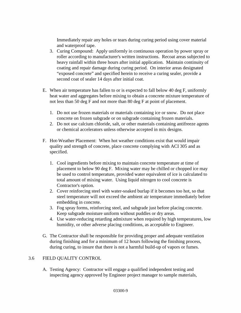
03300-9
Immediately repair any holes or tears during curing period using cover material and waterproof tape.
3. Curing Compound: Apply uniformly in continuous operation by power spray or roller according to manufacturer's written instructions. Recoat areas subjected to heavy rainfall within three hours after initial application. Maintain continuity of coating and repair damage during curing period. On interior areas designated “exposed concrete” and specified herein to receive a curing sealer, provide a second coat of sealer 14 days after initial coat.
E. When air temperature has fallen to or is expected to fall below 40 deg F, uniformly
heat water and aggregates before mixing to obtain a concrete mixture temperature of not less than 50 deg F and not more than 80 deg F at point of placement.
1. Do not use frozen materials or materials containing ice or snow. Do not place
concrete on frozen subgrade or on subgrade containing frozen materials. 2. Do not use calcium chloride, salt, or other materials containing antifreeze agents
or chemical accelerators unless otherwise accepted in mix designs.
F. Hot-Weather Placement: When hot weather conditions exist that would impair quality and strength of concrete, place concrete complying with ACI 305 and as specified.
1. Cool ingredients before mixing to maintain concrete temperature at time of
placement to below 90 deg F. Mixing water may be chilled or chopped ice may be used to control temperature, provided water equivalent of ice is calculated to total amount of mixing water. Using liquid nitrogen to cool concrete is Contractor's option.
2. Cover reinforcing steel with water-soaked burlap if it becomes too hot, so that steel temperature will not exceed the ambient air temperature immediately before embedding in concrete.
3. Fog spray forms, reinforcing steel, and subgrade just before placing concrete. Keep subgrade moisture uniform without puddles or dry areas.
4. Use water-reducing retarding admixture when required by high temperatures, low humidity, or other adverse placing conditions, as acceptable to Engineer.
G. The Contractor shall be responsible for providing proper and adequate ventilation
during finishing and for a minimum of 12 hours following the finishing process, during curing, to insure that there is not a harmful build-up of vapors or fumes.
3.6 FIELD QUALITY CONTROL
A. Testing Agency: Contractor will engage a qualified independent testing and inspecting agency approved by Engineer project manager to sample materials,
03300-10
perform tests, and submit test reports during concrete placement. Tests will be performed according to ACI 301.
1. Testing Frequency: One composite sample for each day's pour of each concrete
mix exceeding 5 cu. yd., plus one set for each additional 50 cubic yards or fraction thereof.
2. Materials and installed work may require testing and retesting, as directed by Engineer, at any time during progress of work. Retesting of rejected materials and installed work shall be done at the Contractor’s expense.
3. Submit concrete cylinder test reports as results are available. END OF SECTION 03300

03600−1
SECTION 03600
NON-SHRINK GROUT PART 1 - GENERAL 1.1 SCOPE A. Under this heading shall be included the furnishing and installation of non-shrink grouts.
Non-shrink grouts shall be used for the following types of work: setting base plates, bearing plates, handrails, and machinery bases; and for patching and repair of all watertight structures.
B. Included is all labor, materials, equipment, tools and energy necessary to accomplish the
grouting work. 1.2 RELATED WORK SPECIFIED IN OTHER SECTIONS A. Patching and repair of concrete surfaces, where non-shrink grout is not specified nor noted
on the Contract Plans, is included under Cast-in-Place Concrete, Section 03300. B. Grouting and re-pointing of masonry joints is included under Unit Masonry Assemblies,
Section 04810. PART 2 - PRODUCTS 2.1 MATERIALS A. Non-Shrink/Non-Metallic Grout (Type "A") 1. Grout shall be factory-mixed containing natural aggregates formulated to be used at
any consistency from extremely fluid to damp pack (Plastic). The grout shall be similar in finished appearance to adjacent concrete or mortar. The grout shall be free of gas producing agents, oxidizing catalysts and inorganic accelerators.
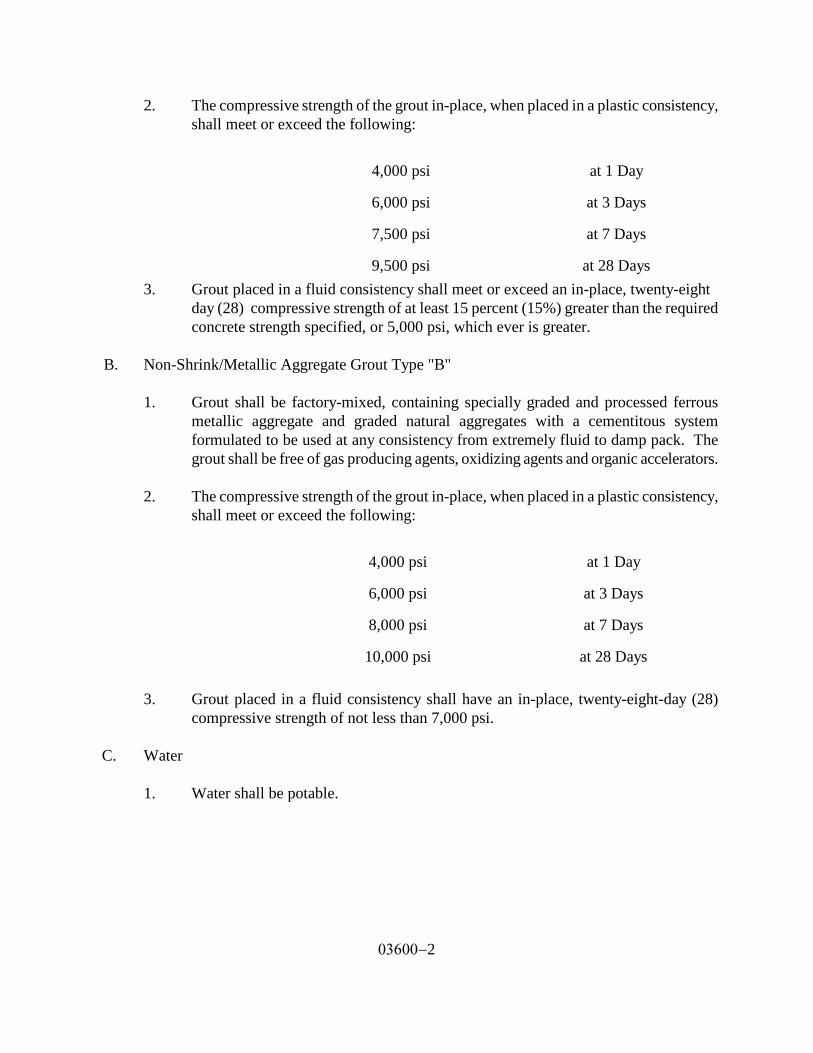
03600−2
2. The compressive strength of the grout in-place, when placed in a plastic consistency, shall meet or exceed the following:
4,000 psi
at 1 Day
6,000 psi
at 3 Days
7,500 psi
at 7 Days
9,500 psi
at 28 Days 3. Grout placed in a fluid consistency shall meet or exceed an in-place, twenty-eight day (28) compressive strength of at least 15 percent (15%) greater than the required concrete strength specified, or 5,000 psi, which ever is greater.
B. Non-Shrink/Metallic Aggregate Grout Type "B" 1. Grout shall be factory-mixed, containing specially graded and processed ferrous
metallic aggregate and graded natural aggregates with a cementitous system formulated to be used at any consistency from extremely fluid to damp pack. The grout shall be free of gas producing agents, oxidizing agents and organic accelerators.
2. The compressive strength of the grout in-place, when placed in a plastic consistency,
shall meet or exceed the following:
4,000 psi
at 1 Day
6,000 psi
at 3 Days
8,000 psi
at 7 Days
10,000 psi
at 28 Days
3. Grout placed in a fluid consistency shall have an in-place, twenty-eight-day (28)
compressive strength of not less than 7,000 psi. C. Water
1. Water shall be potable.
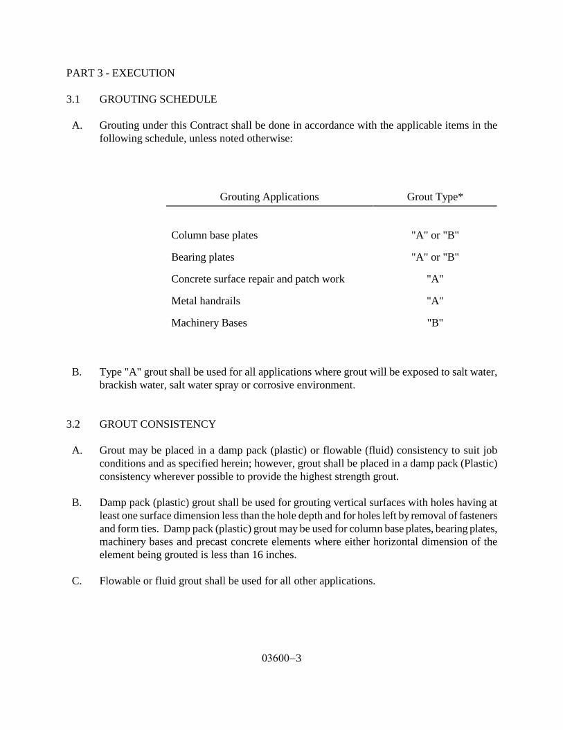
03600−3
PART 3 - EXECUTION 3.1 GROUTING SCHEDULE A. Grouting under this Contract shall be done in accordance with the applicable items in the
following schedule, unless noted otherwise:
Grouting Applications
Grout Type*
Column base plates
"A" or "B"
Bearing plates
"A" or "B"
Concrete surface repair and patch work
"A"
Metal handrails
"A"
Machinery Bases
"B"
B. Type "A" grout shall be used for all applications where grout will be exposed to salt water, brackish water, salt water spray or corrosive environment.
3.2 GROUT CONSISTENCY A. Grout may be placed in a damp pack (plastic) or flowable (fluid) consistency to suit job
conditions and as specified herein; however, grout shall be placed in a damp pack (Plastic) consistency wherever possible to provide the highest strength grout.
B. Damp pack (plastic) grout shall be used for grouting vertical surfaces with holes having at
least one surface dimension less than the hole depth and for holes left by removal of fasteners and form ties. Damp pack (plastic) grout may be used for column base plates, bearing plates, machinery bases and precast concrete elements where either horizontal dimension of the element being grouted is less than 16 inches.
C. Flowable or fluid grout shall be used for all other applications.

03600−4
3.3 SURFACE PREPARATION A. General
1. Concrete surfaces to receive grout shall be rough and reasonably level. Laitance shall be removed to sound concrete. The surfaces, including bolt holes shall be saturated with water for twenty-four (24) hours prior to grouting, unless otherwise recommended by the grouting manufacturer.
2. Where grout is to be used to repair damaged concrete surfaces, the damaged or
honeycombed concrete shall be removed to sound concrete by chipping.
3. Metal surfaces to receive grout shall be derusted, cleaned of oil, grease and other deleterious substances by means of appropriate solvents, wire brushing or a combination of both.
B. Formwork 1. Forms shall be provided for grout placed at a flowable (fluid) consistency.
2. Forms shall be strong, tight and shall be braced so they will not leak or buckle under the weight of fluid grout. On the placing side, forms shall extend 3 inches from base plate, unless otherwise indicated, and shall slant at a 45 degree angle. Grout shall be poured directly on the slanted face. On other sides, the form shall be placed 2- inch or more away from base of the bedplate and 1 inch or more higher than the underside of the plate.
a. Forms shall be caulked with grout or a sand-cement mortar to prevent
leakage. Expanded polystyrene or other means shall be used to caulk between foundation and portions of the element being grouted to seal off areas where grout is not required.
b. Provide air relief openings to avoid entrapment of air. 3.4 GROUT PREPARATION, PLACEMENT AND CURING A. Grout shall be mixed to proper consistency, placed, and cured as instructed by the grout
manufacturer. A paddle-type mortar mixer or other suitable mechanical mixer shall be used unless otherwise allowed.
B. Any nearby vibrating machinery or equipment should be shut down to avoid disturbing the
bonding or initial set of freshly placed grout.

03600−5
C. Mixing water temperature shall not be less than 40 Degrees F. nor exceed 80 degrees F. unless more stringent conditions are required by the grout manufacturer.
D. Grout shall be placed at a temperature of 65 to 75 Degrees; and maintained at this
temperature range for twenty-four (24) hours and above 40 Degrees F. thereafter until the grout strength exceeds 4,000 psi.
E. Grout used for concrete surface repair and patchwork shall be applied to a small area and
allowed to cure to determine color compatibility (subject to Engineer's review). END OF SECTION 03600
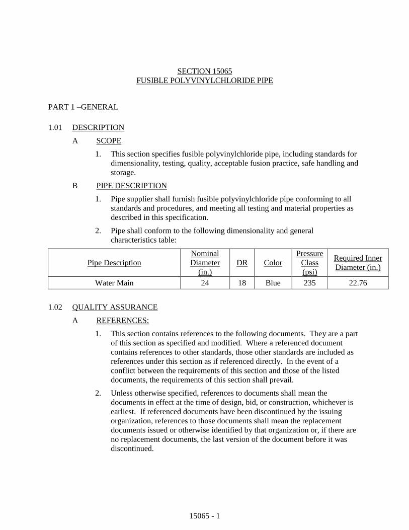
15065 - 1
SECTION 15065
FUSIBLE POLYVINYLCHLORIDE PIPE
PART 1 –GENERAL 1.01
A DESCRIPTION
1. This section specifies fusible polyvinylchloride pipe, including standards for dimensionality, testing, quality, acceptable fusion practice, safe handling and storage.
SCOPE
B 1. Pipe supplier shall furnish fusible polyvinylchloride pipe conforming to all
standards and procedures, and meeting all testing and material properties as described in this specification.
PIPE DESCRIPTION
2. Pipe shall conform to the following dimensionality and general characteristics table:
Pipe Description Nominal Diameter
(in.) DR Color
Pressure Class (psi)
Required Inner Diameter (in.)
Water Main 24 18 Blue 235 22.76
1.02 A QUALITY ASSURANCE
1. This section contains references to the following documents. They are a part of this section as specified and modified. Where a referenced document contains references to other standards, those other standards are included as references under this section as if referenced directly. In the event of a conflict between the requirements of this section and those of the listed documents, the requirements of this section shall prevail.
REFERENCES:
2. Unless otherwise specified, references to documents shall mean the documents in effect at the time of design, bid, or construction, whichever is earliest. If referenced documents have been discontinued by the issuing organization, references to those documents shall mean the replacement documents issued or otherwise identified by that organization or, if there are no replacement documents, the last version of the document before it was discontinued.

15065 - 2
3. Where document dates are given in the following listing, references to those documents shall mean the specific document version associated with that date, regardless of whether the document has been superseded by a version with a later date, discontinued or replaced.
Reference Title
ANSI/AWWA C110/A21.10
American National Standard for Ductile-Iron and Gray-Iron Fittings, 3-inch through 48-inch, for Water and Other Liquids
ANSI/AWWA C111/A21.11
American National Standard for Rubber-Gasket Joints for Ductile-Iron Pressure Pipe and Fittings
ANSI/AWWA C153/A21.53
AWWA Standard for Ductile-Iron Compact Fittings for Water Service
AWWA C605 Standard for Underground Installation of Polyvinyl Chloride (PVC) Pressure Pipe and Fittings for Water
AWWA C651 Standard for Disinfecting Water Mains
AWWA C900 Standard for Polyvinyl Chloride (PVC) Pressure Pipe and Fabricated Fittings, 4 in. through 12 in. (100mm Through 300mm), for Water Distribution
AWWA C905 Standard for Polyvinyl Chloride (PVC Pressure Pipe and Fabricated Fittings, 14 in. through 48 in. (350mm Through 1200mm), for Water Distribution and Transmission
AWWA M23 AWWA Manual of Supply Practices PVC Pipe—Design and Installation, Second Edition
ASTM C923 Standard Specification for Resilient Connectors Between Reinforced Concrete Manhole Structures, Pipes and Laterals
ASTM D1784 Rigid Poly (Vinyl Chloride) (PVC) Compounds and Chlorinated Poly (Vinyl Chloride) (CPVC) Compounds
ASTM D1785 Poly (Vinyl Chloride) (PVC) Plastic Pipe, Schedules 40, 80, and 120
ASTM D2152 Test Method for Degree of Fusion of Extruded Poly(Vinyl Chloride) (PVC) Pipe and Molded Fittings by Acetone Immersion
ASTM D2241 Poly (Vinyl Chloride) (PVC) Plastic Pipe (SDR-PR)
ASTM D2665 Poly (Vinyl Chloride) (PVC) Plastic Drain, Waste, and Vent Pipe and Fittings
ASTM D3034 Standard Specification for Type PSM Poly(Vinyl Chloride) (PVC) Sewer Pipe and Fittings
ASTM F477 Elastomeric Seals (Gaskets) for Joining Plastic Pipe

15065 - 3
Reference Title
ASTM F679 Standard Specification for Poly(Vinyl Chloride) (PVC) Large Diameter Plastic Gravity Sewer Pipe and Fittings
ASTM F1057 Standard Practice for Estimating the Quality of Extruded Poly (Vinyl Chloride) (PVC) Pipe by the Heat Reversion Technique
ASTM F1417 Standard Test Method for Installation Acceptance of Plastic Gravity Sewer Lines Using Low-Pressure Air
UNI-B-6 Recommended Practice for Low-Pressure Air Testing of Installed Sewer Pipe
UNI-PUB-08 Tapping Guide for PVC Pressure Pipe
NSF-14 Plastics Piping System Components and Related Materials
NSF-61 Drinking Water System Components--Health Effects
PPI TR-2 PVC Range Composition Listing of Qualified Ingredients
B 1. All piping shall be made from PVC compound conforming to cell
classification 12454 per ASTM D1784.
MANUFACTURER REQUIREMENTS
C 1. Fusion Technician shall be fully qualified by the pipe supplier to install
fusible polyvinylchloride pipe of the type(s) and size(s) being used. Qualification shall be current as of the actual date of fusion performance on the project.
FUSION TECHNICIAN REQUIREMENTS
D 1. Fusible polyvinylchloride pipe shall be used as manufactured under the trade
names Fusible C-900®, Fusible C-905®, and FPVC®, for Underground Solutions, Inc., Poway, CA, (858) 679-9551. Fusion process shall be as patented by Underground Solutions, Inc., Poway, CA, Patent No. 6,982,051. Owner and engineer are aware of no other supplier of fusible polyvinylchloride pipe that is an equal to this specified pipe supplier and products.
SPECIFIED PIPE SUPPLIERS
E 1. The pipe shall be warranted for one year per the pipe supplier’s standard
terms.
WARRANTY
2. In addition to the standard pipe warranty, the fusion services shall be warranted for one year per the fusion service provider’s standard terms.

15065 - 4
F 1. The following PRODUCT DATA is required from the pipe supplier and/or
fusion provider:
PRE-CONSTRUCTION SUBMITTALS
1) Pipe Size
2) Dimensionality
3) Pressure Class per applicable standard
4) Color
5) Recommended Minimum Bending Radius
6) Recommended Maximum Safe Pull Force
7) Fusion technician qualification indicating conformance with this specification
G 1. The following AS-RECORDED DATA is required from the contractor
and/or fusion provider to the owner or pipe supplier upon request:
POST-CONSTRUCTION SUBMITTALS
1) Approved datalogger device reports
2) Fusion joint documentation containing the following information:
a) Pipe Size and Thickness
b) Machine Size
c) Fusion Technician Identification
d) Job Identification
e) Fusion Joint Number
f) Fusion, Heating, and Drag Pressure Settings
g) Heat Plate Temperature
h) Time Stamp
i) Heating and Cool Down Time of Fusion
j) Ambient Temperature
15065 - 5
PART 2 – PRODUCTS 2.01 FUSIBLE POLYVINYLCHLORIDE PRESSURE PIPE FOR POTABLE WATER
A Fusible polyvinylchloride pipe shall conform to AWWA C900, AWWA C905, ASTM D2241 or ASTM D1785 for standard dimensions, as applicable. Testing shall be in accordance with the referenced AWWA standards for all pipe types.
B Fusible polyvinylchloride pipe shall be extruded with plain ends. The ends shall be square to the pipe and free of any bevel or chamfer. There shall be no bell or gasket of any kind incorporated into the pipe.
C Fusible polyvinylchloride pipe shall be manufactured in a standard 40’ nominal length, or custom lengths as specified.
D Fusible polyvinylchloride pipe shall be blue in color for potable water use.
E Pipe shall be marked as follows:
1. Nominal pipe size
2. PVC
3. Dimension Ratio, Standard Dimension Ratio, or Schedule
4. AWWA pressure class, or standard pressure rating for non-AWWA pipe, as applicable
5. AWWA standard designation number, or pipe type for non-AWWA pipe, as applicable
6. NSF-61 mark verifying suitability for potable water service
7. Extrusion production-record code
8. Trademark or trade name
9. Cell Classification 12454 and/or PVC material code 1120 may also be included
F Pipe shall be homogeneous throughout and be free of visible cracks, holes, foreign material, blisters, or other visible deleterious faults.
2.02 FUSION JOINTS
A Unless otherwise specified, fusible polyvinylchloride pipe lengths shall be assembled in the field with butt-fused joints. The Contractor shall follow the pipe supplier’s written guidelines for this procedure. All fusion joints shall be completed as described in this specification.
2.03 CONNECTIONS AND FITTINGS FOR PRESSURE APPLICATIONS
A Connections shall be defined in conjunction with the coupling of project piping, as well as the tie-ins to other piping systems.

15065 - 6
B DUCTILE IRON MECHANICAL AND FLANGED FITTINGS
Acceptable fittings for use with fusible polyvinylchloride pipe shall include standard ductile iron fittings conforming to AWWA/ANSI C110/A21.10, or AWWA/ANSI C153/A21.53 and AWWA/ANSI C111/A21.11.
1. Connections to fusible polyvinylchloride pipe may be made using a restrained or non-restrained retainer gland product for PVC pipe, as well as for MJ or flanged fittings.
2. Bends, tees and other ductile iron fittings shall be restrained with the use of thrust blocking or other means as indicated in the construction documents.
3. Ductile iron fittings and glands must be installed per the manufacturer’s guidelines.
C PVC GASKETED, PUSH-ON FITTINGS
Acceptable fittings for use with fusible polyvinylchloride pipe shall include standard PVC pressure fittings conforming to AWWA C900 or AWWA C905.
1. Acceptable fittings for use joining fusible polyvinylchloride pipe other sections of fusible polyvinylchloride pipe or other sections of PVC pipe shall include gasketed PVC, push-on type couplings and fittings, including bends, tees, and couplings as shown in the drawings.
2. Bends, tees and other PVC fittings shall be restrained with the use of thrust blocking or other restraint products as indicated in the construction documents.
3. PVC gasketed, push-on fittings and mechanical restraints, if used, must be installed per the manufacturer’s guidelines.
D SLEEVE-TYPE COUPLINGS
1. Sleeve-type mechanical couplings shall be manufactured for use with PVC pressure pipe, and may be restrained or unrestrained as indicated in the construction documents.
2. Sleeve-type couplings shall be rated at the same or greater pressure carrying capacity as the pipe itself.
E EXPANSION AND FLEXIBLE COUPLINGS
1. Expansion-type mechanical couplings shall be manufactured for use with PVC pipe, and may be restrained or unrestrained as indicated in the construction documents.
2. Expansion-type mechanical couplings shall be rated at the same or greater pressure carrying capacity as the pipe itself.
F CONNECTION HARDWARE
Bolts and nuts for buried service shall be made of non-corrosive, high-strength,

15065 - 7
low-alloy steel having the characteristics specified in ANSI/AWWA C111/A21.11, regardless of any other protective coating.
PART 3 - EXECUTION 3.01 DELIVERY AND OFF-LOADING
A All pipe shall be bundled or packaged in such a manner as to provide adequate protection of the ends during transportation to the site. Any pipe damaged in shipment shall be replaced as directed by the owner or engineer.
B Each pipe shipment should be inspected prior to unloading to see if the load has shifted or otherwise been damaged. Notify owner or engineer immediately if more than immaterial damage is found. Each pipe shipment should be checked for quantity and proper pipe size, color, and type.
C Pipe should be loaded, off-loaded, and otherwise handled in accordance with AWWA M23, and all of the pipe supplier’s guidelines shall be followed.
D Off-loading devices such as chains, wire rope, chokers, or other pipe handling implements that may scratch, nick, cut, or gouge the pipe are strictly prohibited.
E During removal and handling, be sure that the pipe does not strike anything. Significant impact could cause damage, particularly during cold weather.
F If appropriate unloading equipment is not available, pipe may be unloaded by removing individual pieces. Care should be taken to insure that pipe is not dropped or damaged. Pipe should be carefully lowered, not dropped, from trucks.
3.02 HANDLING AND STORAGE
A Any length of pipe showing a crack or which has received a blow that may have caused an incident fracture, even though no such fracture can be seen, shall be marked as rejected and removed at once from the work. Damaged areas, or possible areas of damage may be removed by cutting out and removing the suspected incident fracture area. Limits of the acceptable length of pipe shall be determined by the owner or engineer.
B Any scratch or gouge greater than 10% of the wall thickness will be considered significant and can be rejected unless determined acceptable by the owner or engineer.
C Pipe lengths should be stored and placed on level ground. Pipe should be stored at the job site in the unit packaging provided by the manufacturer. Caution should be exercised to avoid compression, damage, or deformation to the ends of the pipe. The interior of the pipe, as well as all end surfaces, should be kept free from dirt and foreign matter.
D Pipe shall be handled and supported with the use of woven fiber pipe slings or approved equal. Care shall be exercised when handling the pipe to not cut, gouge, scratch or otherwise abrade the piping in any way.
15065 - 8
E If pipe is to be stored for periods of 1 year or longer, the pipe should be shaded or otherwise shielded from direct sunlight. Covering of the pipe which allows for temperature build-up is strictly prohibited. Pipe should be covered with an opaque material while permitting adequate air circulation above and around the pipe as required to prevent excess heat accumulation.
F Pipe shall be stored and stacked per the pipe supplier’s guidelines.
3.03 FUSION PROCESS
A GENERAL
1. Fusible polyvinylchloride pipe will be handled in a safe and non-destructive manner before, during, and after the fusion process and in accordance with this specification and pipe supplier’s guidelines.
2. Fusible polyvinylchloride pipe will be fused by qualified fusion technicians, as documented by the pipe supplier.
3. Each fusion joint shall be recorded and logged by an electronic monitoring device (data logger) connected to the fusion machine.
4. Only appropriately sized and outfitted fusion machines that have been approved by the pipe supplier shall be used for the fusion process. Fusion machines must incorporate the following elements:
a) HEAT PLATE - Heat plates shall be in good condition with no deep gouges or scratches. Plates shall be clean and free of any debris or contamination. Heater controls shall function properly; cord and plug shall be in good condition. The appropriately sized heat plate shall be capable of maintaining a uniform and consistent heat profile and temperature for the size of pipe being fused, per the pipe supplier’s guidelines.
b) CARRIAGE – Carriage shall travel smoothly with no binding at less than 50 psi. Jaws shall be in good condition with proper inserts for the pipe size being fused. Insert pins shall be installed with no interference to carriage travel.
c) GENERAL MACHINE - Overview of machine body shall yield no obvious defects, missing parts, or potential safety issues during fusion.
d) DATA LOGGING DEVICE – An approved datalogging device with the current version of the pipe supplier’s recommended and compatible software shall be used. Datalogging device operations and maintenance manual shall be with the unit at all times. If fusing for extended periods of time, an independent 110V power source shall be available to extend battery life.
5. Other equipment specifically required for the fusion process shall include the
15065 - 9
following:
a) Pipe rollers shall be used for support of pipe to either side of the machine
b) A weather protection canopy that allows full machine motion of the heat plate, fusion assembly and carriage shall be provided for fusion in inclement, extreme temperatures, and /or windy weather, per the pipe supplier’s recommendations.
c) An infrared (IR) pyrometer for checking pipe and heat plate temperatures.
d) Fusion machine operations and maintenance manual shall be kept with the fusion machine at all times.
e) Facing blades specifically designed for cutting fusible polyvinylchloride pipe shall be used.
B JOINT RECORDING
Each fusion joint shall be recorded and logged by an electronic monitoring device (data logger) connected to the fusion machine. The fusion data logging and joint report shall be generated by software developed specifically for the butt-fusion of fusible polyvinyl chloride pipe. The software shall register and/or record the parameters required by the pipe supplier and these specifications. Data not logged by the data logger shall be logged manually and be included in the Fusion Technician’s joint report.
3.04 GENERAL INSTALLATION
A Installation guidelines from the pipe supplier shall be followed for all installations.
B The fusible polyvinylchloride pipe will be installed in a manner so as not to exceed the recommended bending radius.
C Where fusible polyvinylchloride pipe is installed by pulling in tension, the recommended Safe Pulling Force established by the pipe supplier shall not be exceeded.
3.05 PREPARATION PRIOR TO MAKING CONNECTIONS INTO EXISTING PIPING SYSTEMS
A Approximate locations for existing piping systems are shown in the construction documents. Prior to making connections into existing piping systems, the contractor shall:
1. Field verify location, size, piping material, and piping system of the existing pipe.
2. Obtain all required fittings, which may include saddles, sleeve type couplings, flanges, tees, or others as shown in the construction documents.
15065 - 10
3. Have installed all temporary pumps and/or pipes in accordance with established connection plans.
B Unless otherwise approved, new piping systems shall be completely assembled and successfully tested prior to making connections into existing pipe systems.
3.06 PIPE SYSTEM CONNECTIONS
A Pipe connections shall be installed per applicable standards and regulations, as well as per the connection manufacturer’s guidelines and as indicated in the construction documents. Pipe connections to structures shall be installed per applicable standards and regulations, as well as per the connection manufacturer’s guidelines.
3.07 TAPPING FOR POTABLE AND NON-POTABLE WATER APPLICATIONS
A Tapping shall be performed using standard tapping saddles designed for use on PVC piping in accordance with AWWA C605. Tapping shall be performed only with use of tap saddles or sleeves. NO DIRECT TAPPING WILL BE PERMITTED. Tapping shall be performed in accordance with the applicable sections for Saddle Tapping per Uni-Pub-8.
B All connections requiring a larger diameter than that recommended by the pipe supplier, shall be made with a pipe connection as specified and indicated on the drawings.
C Equipment used for tapping shall be made specifically for tapping PVC pipe:
1. Tapping bits shall be slotted “shell” style cutters, specifically made for PVC pipe. ‘Hole saws’ made for cutting wood, steel, ductile iron, or other materials are strictly prohibited.
2. Manually operated or power operated drilling machines may be used.
D Taps may be performed while the pipeline is filled with water and under pressure (‘wet’ tap,) or when the pipeline is not filled with water and not under pressure (‘dry’ tap).
3.08 TESTING
A Testing shall comply with all applicable jurisdictional building codes, statutes, standards, regulations, and laws.
B HYDROSTATIC TESTING AND LEAKAGE TESTING FOR PRESSURE PIPING
1. Hydrostatic and leakage testing for piping systems that contain mechanical jointing as well as fused PVC jointing shall comply with AWWA C605.
2. Unless agreed to or otherwise designated by the owner or engineer, for a simultaneous hydrostatic and leakage test following installation, a pressure equal to 150% of working pressure at point of test, but not less than 125% of

15065 - 11
normal working pressure at highest elevation shall be applied. The duration of the pressure test shall be for two (2) hours.
3. If hydrostatic testing and leakage testing are performed at separate times, follow procedures as outlined in AWWA C605.
4. In preparation for pressure testing the following parameters must be followed:
1) All air must be vented from the pipeline prior to pressurization. This may be accomplished with the use of the air relief valves or corporation stop valves, vent piping in the testing hardware or end caps, or any other method which adequately allows air to escape the pipeline at all high points. Venting may also be accomplished by ‘flushing’ the pipeline in accordance with the parameters and procedures as described in AWWA C605.
2) The pipeline must be fully restrained prior to pressurization. This includes complete installation of all mechanical restraints per the restraint manufacturer’s guidelines, whether permanent or temporary to the final installation. This also includes the installation and curing of any and all required thrust blocking. All appurtenances included in the pressure test, including valves, blow-offs, and air-relief valves shall be checked for proper installation and restraint prior to beginning the test.
3) Temporary pipeline alignments that are being tested, such as those that are partially installed in their permanent location shall be configured to minimize the amount of potentially trapped air in the pipeline.
C DISINFECTION OF THE PIPELINE FOR POTABLE WATER PIPING
1. After installation, the pipeline, having passed all required testing, shall be disinfected prior to being put into service. Unless otherwise directed by the owner or engineer, the pipeline will be disinfected per AWWA C651.
D PARTIAL TESTING
1. Segments of the pipe may be tested separately in accordance with standard testing procedure, as approved by the owner and engineer.
**END OF SECTION**
Great Swamp EMS Expansion 16000 - 1 HGB Client
DIVISION 16 - ELECTRICAL 16010 - BASIC ELECTRICAL REQUIREMENTS 1.1 QUALITY ASSURANCE
A. All electrical work shall be in accordance with the following codes and agencies:
1. The National Electrical Code (NFPA-70), 2014 Edition with South Carolina Amendments.
2. The Standard Building Code, 2012 Edition with South Carolina Amendments. 3. Regulations of the local utility company concerning metering and service entrance. 4. State and local ordinances governing electrical work.
B. All materials shall be new and shall conform to standards where such have been established for the particular material. All UL listed equipment shall bear the UL label.
1.2 PERMITS
A. Obtain all permits and inspections required for the work involved. Deliver to the owner all certificates of inspection.
1.3 WARRANTY
A. The contractor shall warrant to the owner that all work shall be free from defects and will conform to the contract documents. This warranty shall extend not less than one year from the date of beneficial occupancy.
1.4 DRAWINGS
A. The drawings indicate the general arrangement of electrical equipment, based on one manufacturer’s product. Coordinate installation of equipment with all other trades. Do not scale drawings for connection locations. Bring all discrepancies to the immediate attention of the Engineer.
B. Contractor shall install and circuit all electrical work as indicated on drawings unless specific construction requires a change or rerouting of this work. He shall keep a record of the location of all concealed work, including the underground utility lines. He shall document all changes in the manner specified by the General Conditions, Special Conditions and Supplementary General Conditions.
1.5 EQUIPMENT REQUIRING ELECTRICAL SERVICE
A. Review all specification sections and drawings for equipment requiring electrical service. Provide service to and make connections to all such equipment.
B. Drawings are based on design loads of one manufacturer. If equipment actually furnished have loads, numbers of connections, or voltages other than those indicated on the drawings, then control equipment, feeders, and overcurrent devices shall be adjusted as required, at no additional cost to the owner. Such adjustments are subject to review by the engineer.

Great Swamp EMS Expansion 16000 - 2 HGB Client
C. Catalog numbers indicated with equipment, devices and lighting fixtures are for convenience only. Errors or obsolescence shall not relieve the furnishing of items which meet the technical description given in specifications, noted, or required by function designated.
1.6 SITE INVESTIGATION AND RENOVATION CONDITIONS
A. Prior to submitting bids for the project, visit the site to become familiar with existing conditions. The project shall be restored to its existing condition, with the exception of work under this contract, prior to final payment.
1.7 PRODUCT DELIVERY, STORAGE, HANDLING, AND PROTECTION
A. Provide a dry, weather tight space for storing materials. Store packaged materials in original undamaged condition with manufacturer's labels and seals intact. Handle and store material in accordance with standards to prevent damage. Equipment and materials shall not be installed until such time as the environmental conditions of the job site are suitable. Replace damaged materials.
1.8 CLEANING AND PAINTING
A. Remove oil, dirt, grease and foreign materials from all equipment to provide a clean surface. Touch up scratched or marred surfaces of lighting fixtures, panelboard and cabinet trims, and equipment enclosures with paint manufactured specifically for that purpose.
16100 - BASIC MATERIALS
2.1 RACEWAYS
A. The following specifications and standards are incorporated into and become a part of this specification:
1. Underwriter's Laboratory, Inc. Publications 1, 6, 467, 651, 797, 1242. 2. American National Standards Institute C-80.1, C-80.3.
B. Raceway is required for all wiring, unless specifically indicated or specified otherwise. The minimum size of conduit shall be 3/4", but shall not be less than size indicated on the drawings or required by the NEC.
C. Conduits shall be galvanizd rigid steel (GRS) or intermediate metal conduit (IMC) except for the following conditions:
1. Conduits installed within concrete slabs shall be GRS, IMC, or schedule 80 heavy wall PVC. Where transition is made from raceway in slab to any type of raceway out of slab, make transition with a rigid galvanized elbow.
2. Conduits installed in direct contact with earth shall be schedule 80, heavy wall PVC. 3. Use flexible conduit for connections to motors, and all vibrating equipment.
a. Length shall not exceed 18”. b. Maintain ground continuity through flexible conduit with a green equipment
grounding conductor. c. Liquid-tight flexible conduit shall be used in exterior installations.
Great Swamp EMS Expansion 16000 - 3 HGB Client
D. GRS and IMC fittings shall be standard threaded couplings, threaded hubs, bushings, and elbows. All GRS and IMC fittings shall be steel or malleable iron; set screw or non-threaded fittings are not permitted. Non-metallic conduit fittings shall be of the same material as the conduit furnished and shall be the product of the same manufacturer.
E. All conduit support parts and hardware shall be stainless steel. Conduit straps shall be two-piece pipe clamp for RGS or IMC. The clamp shall include machine screw and square nut, 304 stainless steel, B-line B-2000 series or equal. Conduit support channels shall be 1 5/8” x 1 5/8” – 12 gauge channel, 304 stainless steel; B-line B22 series or equal. Wire or chain is not acceptable for conduit hangers.
F. Leave all empty conduits with a 200 lb. test nylon cord pull line. Complete raceway runs prior to installation of wires or cables. Deformed conduits shall be replaced. Protect conduits against dirt, plaster, and foreign debris with conduit plugs.
G. Fasten conduit support devices to structure with expansion anchors on solid masonry or concrete, and machine bolts or clamps on steel. Seal all conduits with insulating electrical putty to prevent entrance of moisture.
H. Conduit shall be run parallel or at right angles to structural members. Support branch circuit conduits at intervals not exceeding 10 feet, and within 3 feet of each box or change of direction.
2.2 WIRES AND CABLES
A. The following specifications and standards are incorporated into and become a part of this specification:
1. Underwriter's Laboratories, Inc. Publications 44, 83, 486, 493. 2. Insulated Cable Engineers Association Standards S-61-402, S-66-524. 3. National Electrical Manufacturer's Standards WC-5, WC-7.
B. Conductors shall be electrically continuous and free from short circuits or grounds.
C. All open, shorted, or grounded conductors and any with damaged insulation shall be removed and replaced with new material free from defects.
D. Conductor size shall be minimum of No. 12 AWG, unless larger size is required by the drawings or the NEC. Insulation voltage level rating shall be 600 volts. All wire and cable shall bear the UL label.
E. Conductors No. 12 and smaller shall be solid copper, 90 degrees C. type THWN/THHN. Conductors larger than No. 10 shall be stranded copper, 90 degrees C. type THWN/THHN, or XHHW. Fixture wire shall be No. 16 AWG silicone rubber insulated, stranded fixture wire type SFF-2 or No. 16 thermoplastic nylon jacketed stranded fixture wire type TFFN.
F. Color code all conductors. No. 6 and smaller shall have solid color compound or coating. No. 4 and larger shall have solid color compound or colored phase tape; tape shall be installed on conductors in every box, termination point, cabinet, or enclosure. Coding shall be as follows:
Great Swamp EMS Expansion 16000 - 4 HGB Client
1. 240/120 volt single phase three wire system: Phase A-black, Phase B-red, neutral-white.
2. Grounding conductors shall be green or green traced.
G. Maintain phase rotation established per N.E.C. at service equipment throughout entire project.
H. Group and lace with nylon tie straps all conductors within enclosures. Make splices in conductors only within junction boxes, wiring troughs, or other NEC approved enclosures. Do not splice conductors in pull boxes, panelboards, safety switches, or motor control enclosures. Identify each conductor as to circuit connection in all boxes and enclosures.
I. Terminate stranded conductors No. 10 AWG and smaller with crimp-type lug or stud. Crimp terminal shall be the configuration type suitable for terminal point.
J. Torque each terminal connection to the manufacturer’s recommended torque value. A calibrated torquing tool shall be used to insure proper torque application.
2.3 BOXES
A. The following specifications and standards are incorporated into and become a part of this specification:
1. Underwriter’s Laboratories, Inc. Publications 50, 467, 514.
B. Boxes shall be rustproof cast metal. Outlet boxes for GFI receptacles shall be 2 3/4" deep.
C. Outlet boxes for switches and receptacles in exposed wiring systems shall be cast FS type with matching device plate. For exterior installations, use weatherproof in-use type covers.
D. Dimensions of pull and junction boxes shall not be less than those required by the NEC for the number, size, and position of conductors entering the box. Wood supports within pull boxes are not acceptable. Provide box covers for all boxes.
E. All boxes shall be completely accessible and as required by the NEC. Provide an outlet box for each for each device. Box sizes shall be increased from those outlined above if required by Article 314 of the NEC.
F. Support every box from structure. Secure to solid masonry or concrete with expansion anchors, metal studs with spring steel clamp.
G. After completion, using indelible ink wide tip marker, indicate on the cover of each junction and pull box the designation of each circuit contained therein.
2.4 WIRING DEVICES
A. The following specifications and standards are incorporated into and become a part of this specification:
1. National Electrical Manufacturer's Association Publications WD-1, WD-5.
B. Weatherproof, 20 amp, 277 volt switches shall be Hubbell 1281-1750. Equivalent switches manufactured by Arrow Hart, Legrand, or Leviton are acceptable.

Great Swamp EMS Expansion 16000 - 5 HGB Client
C. Ground fault interrupter (GFI) receptacles shall be Hubbell GFTWRST83. Equivalent receptacles manufactured by Arrow Hart, Legrand, or Leviton are acceptable.
D. All devices installed in areas exposed to the weather shall be provided with a weatherproof, in-use type device plate; Hubbell RW57300 or approved equal.
E. All devices shall be white.
2.5 SUPPORTING DEVICES
A. Provide and install supporting devices which comply with manufacturer's standard materials, design, and construction in accordance with published standards and as required for complete installation.
B. Coordinate with other electrical work, including raceway and wiring work, as necessary to interface installation of supporting devices. Install hangars, supports, clamps, and attachments to support piping properly from building structure only. Torque sleeve seal nuts, complying with manufacturer's recommended values. Ensure that sealing grommets expand to form water-tight seal.
2.6 ELECTRICAL IDENTIFICATION
A. Install engraved plastic - laminate sign on each major unit of electrical equipment. Provide a single line of text, 1/2" high lettering on 1 1/2" high sign (or 2" high sign if 2 lines required). Provide signs for each unit of the following:
1. Panelboards. 2. Electrical cabinets and enclosures. 3. SCADA panel.
16400 - DISTRIBUTION EQUIPMENT
3.1 GROUNDING SYSTEMS
A. Equipment grounding system shall be established with equipment ground conductors. The use of metallic raceways for equipment grounding is not acceptable. Unless indicated otherwise, provide equipment ground the same size as phase conductors.
B. The following specifications and standards are incorporated into and become a part of this specification:
1. Underwriter’s Laboratories, Inc. Publications 44, 83, 467, 486, 493. 2. National Electrical Manufacturer’s Association Standards WC-5, WC-7.
C. Grounding electrode conductors shall be bare or green insulated copper sized as indicated on the drawings. Equipment grounding conductors shall be green insulated type THW, THWN, or XHHW sized as indicated on the drawings. Where sizes are not indicated, grounding conductor shall be sized in accordance with NEC Article 250.
D. Each receptacle and switch device shall be furnished with a grounding screw connected to the metallic device frame. Provide a conductor termination grounding lug bonded to the enclosure of each transformer, motor controller, and disconnect switch.
Great Swamp EMS Expansion 16000 - 6 HGB Client
E. Ground all non-current carrying parts of the electrical system, i.e., wireways, equipment enclosures and frames, junction and outlet boxes, machine frames, and other conductive items in close proximity with electrical circuits.
F. Grounding conductors for branch circuits are not shown on the drawings; however, grounding conductors shall be provided in all branch circuit raceways and cables, including flexible conduit. Grounding conductors shall be the same AWG size as branch circuit conductors.
G. The equipment grounding conductor shall be terminated with a screw or bolt used for no other purpose. Equipment grounding conductors shall terminate on panel board, grounding bus only. Do not terminate on neutral bus.
3.2 PANELBOARDS
A. The following specifications and standards are incorporated into and become a part of this specification:
1. Underwriter's Laboratories, Inc. Publications 50, 67,489. 2. National Electrical Manufacturer's Association Publications PB-1, AB-3.
B. Products of General Electric, Cutler-Hammer, Square D, or Siemens which comply with these specifications are acceptable.
C. All panels and circuit breakers shall be UL listed and bear a UL label. Where panels serve as service entrance equipment, panel shall bear a UL label indicating such. Panels shall be of the dead front safety type. Provide panels complete with factory assembled circuit breakers connected to the bus bars. Number all panel boards in the following sequence: Circuits 1 and 2 - Phase A; circuits 3 and 4 - Phase B.
D. All bus bars shall be copper. Main lugs and main breaker shall be UL approved for copper or aluminum conductors and shall be of a size range for the conductors indicated on the drawings. Each panel shall contain a full size grounding bus and, when required, a full size insulated neutral bus. The neutral and ground busses shall have a sufficient number of lugs to singularly terminate each individual conductor requiring a connection. The ground bus shall be brazed or riveted to the panel enclosure, but not attached to the panel interior. Where designated, each "space' shall include all bussing, device supports and connections for future breaker installation.
E. Branch circuit panel board width shall be between 20 and 22 inches; depth shall be 5 3/4" maximum. Provide gutters and bending space to conform with the NEC. Key all panels throughout the project alike.
F. Panels shall be provided with NEMA 4X stainless steel enclosures.
G. Circuit breakers shall be quick-make, quick-break, thermal magnetic type bolted to the bus. Multi-pole breakers shall be common trip and common reset type; tie handle connections are not acceptable. Interrupting ratings on 240 volt systems shall be 10,000 RMS symmetrical amps minimum; provide higher ratings when indicated on the drawings.
Great Swamp EMS Expansion 16000 - 7 HGB Client
H. Mount panel boards with top circuit not more than 6'-6" above finished floor. Enclosures shall be secured by a minimum of four fastening devices. Mount enclosure to metal channel for frame.
I. Provide in each panel board a typewritten circuit directory mounted under clear plastic in metal holder in the door of the panel reflecting all field changes additions. Install push-in knock-out closure plugs in any unused knock-out openings.
END OF SECTION

16226- 1
SECTION 16226 ELECTRIC MOTOR ACTUATOR FOR VALVES
I. General
A. Equipment Requirements: The actuators shall be suitable for use on a 240 volt 1-phase 60 Hz power supply and must include motor, integral reversing starters, local controls and terminals for remote control and indication housed within a self contained, sealed enclosure. Set-up of the actuator shall be carried out without the removal of any covers. Actuator calibration shall be by integral pushbuttons and selector switch. No separate special commissioning tools shall be required. In addition, provision shall be made for the protection of configured actuator settings by means of a password.
B. Actuator sizing:
The actuator shall be sized to guarantee valve closure at the specified torque and/or thrust requirement as indicated by the valve manufacturer or supplier. The actuator must be adequately sized to provide the torque required to operate the valve at 90% of the nominal voltage with the option of operation at up to -30% undervoltage conditions. One actuator size (same outside dimensions) shall be available covering output speeds from 4.8 to 216 rpm for a given torque range, to avoid over sizing and unnecessary weight load on valve stem, flange and yoke. An increase of actuator size caused by higher actuator output speed is not acceptable. The operating speed shall provide valve closing and opening at approximately 12 inches per minute for gate valves, 4 inches per minute for globe valves and as indicated in the valve list for quarter turn valves. Quarter-turn valves shall be furnished with mechanical stops that restrict the valve/actuator travel.
C. Environmental
Actuators shall be suitable for indoor and outdoor use. The actuator shall be capable of functioning in an ambient temperature ranging from -13°F to +160°F (-25°C to +70°C), up to 100% relative humidity.
D. Enclosure
Actuators shall be 0-ring sealed, watertight to NEMA 4X/6 and submersible to IP 68-8 (26 feet (8meters) for 96 hours) in accordance with EN 60529. During submersion it must be possible to operate the actuator at least 10 times. Enclosure must allow for temporary site storage without the need for electrical supply connection. All external fasteners shall be of stainless steel. Gear case shall be cast iron. In order to prevent condensation, a heater must be installed inside the actuator, suitable for continuous operation. Actuator must provide an alarm signal in case of failure of anti condensation heater.
16226- 2
E. Motor
The electric motor shall be Class F insulated, with a duty rating of at least 15 minutes at 104°F (40°C) ambient temperature at an average load of at least 35% of rated actuator torque. Motor shall be specifically designed and built by the actuator manufacturer for electric actuator service characterized by high starting torque, low stall torque and low inertia. Commercially available motors shall not be acceptable. Electrical disconnection of the motor shall be by means of a plug and socket and motor removal shall be possible without loss of lubricant. The actuator must include a device to ensure that the motor runs with the correct rotation for the required direction of valve travel regardless of the connection sequence of the power supply.
F. Motor protection
The following criteria shall be provided for motor protection: 1) The motor shall be de-energized without damage in the event of a stall
condition when attempting to move a jammed valve. 2) The motor shall be de-energized in the event of an overtorque condition 3) Thermal devices (one for each phase of power) shall be imbedded in the motor
windings to de-energize the motor in case of overheating. 4) Lost phase protection.
G. Gearing
The actuator gearing shall be totally enclosed in a grease-filled cast iron gearcase suitable for operation in any orientation. Oil lubrication is not permitted. The gearcase shall contain sensors capable of continuously recording temperatures and vibration within the actuator. Actuator gearing shall be hardened steel with alloy bronze worm wheel. Where required per application, electric actuators will be provided with worm gearboxes. The worm gearboxes shall be supplied with full 360° bronze or ductile iron worm wheels and end-of-travel mechanical stops. Designs with segmented worm gears will not be permitted.
H. Manual operation
Manual operation shall be by handwheel which shall not rotate during motor operation. Handwheel declutch mechanism shall include an output contact to indicate actuator manual operation. Manual operation shall utilize the actuator worm shaft/worm wheel to maintain self-locking gearing and to facilitate changeover from motor to manual operation when the actuator is under load. Actuator designs that bypass electric actuator worm gears when declutched are unacceptable. The declutching from motor operation shall be at the motor shaft to minimize declutching effort. The amount of force required to declutch the actuator shall be the same regardless of the size of the actuator. Designs that break the valve load at the worm and worm gear are unacceptable. Return from manual to electric mode of operation will be automatic upon motor operation. A seized or inoperable motor shall not prevent manual operation.

16226- 3
I. Drive nut and thrust base assembly For multi turn rising stem applications, the drive nut shall be installed in a detachable thrust base. The design shall allow actuator removal from the thrust base, leaving the thrust base attached to the valve to retain valve position. Thrust bearings shall be lubricated by means of an easily accessible grease fitting.
J. Valve position and torque calibration
Position and torque shall be sensed by absolute encoder using hall effect sensors. Incremental encoders requiring batteries to retain settings upon loss of power shall not be accepted. Position and torque settings will be stored in permanent non-volatile memory. Torque and travel adjustment parameters are to be as follows: 1) Position setting range 1 to 500 or 10 to 5,000 turns, with resolution of 2.81
degrees and accuracy to 5.0 degrees of actuator output. 2) Torque setting: 40% to 100% of rated torque. Torque switch bypass to be provided for the torque sensing system to inhibit torque switch trip during unseating or during starting in mid travel against high inertia loads.
II. Electric Actuator Control (contact closure / discrete signals or analog signal)
A. Actuator status indication. Six contacts shall be provided. The contacts shall have a minimum rating of 5A, 250VAC. 1) one contact dedicated for collective fault (phase failure, motor protection
tripped, torque fault) or one of eight other fault groups 2) five additional indication contacts selectable from a list of at least 45
parameters including, but not limited to: end position CLOSED, end position OPEN, selector switch in REMOTE mode, torque fault in CLOSED direction, and torque fault in OPEN direction.
B. Local indication The actuator shall include a digital position indicator with a display from fully
open to fully closed in 1% increments.
Six indicating lights shall be included. Five of which are programmable local indicating lights to indicate functions including, but not limited to: end position CLOSED, end position OPEN, fault, selector switch in REMOTE and actuator moving. The sixth light shall indicate Bluetooth® interface connectivity.
C. Remote position and torque feedback Actuator shall provide a 4 to 20 mA analog position feedback signal. Actuator shall provide a 4 to 20 mA analog torque feedback signal corresponding
to required valve torque for diagnostics and preventive maintenance.
D. Integral starter and transformer The starter shall be suitable for up to 60 starts per hour for open/close service and up to 1500 starts per hour for direct mount actuators used in modulating service.
16226- 4
The applicable number of starts per hour depends on actuator size and output speed.
A removable plug and socket controls housing containing LCD operations and diagnostics display, blue tooth interface, reversing starters or thyristors, power supply/control transformer and local controls capable of: 1) being mounted integrally with the actuator and capable of being re-oriented at 90° increments, so that push buttons and indication lights will face the operator. 2) being wall mounted remotely up to 330 ft (100m) where required by application conditions.
E. Integral local controls and control mode selector. The actuator shall include local Open/Stop/Close/Reset pushbuttons and a
Local/Off/Remote selector switch lockable in any of the three positions. The Reset pushbutton shall be provided to facilitate actuator commissioning. It shall be possible to select maintained or non-maintained control independently for either the local or remote modes. It shall be possible to program the output direction of the actuator (clockwise or counterclockwise to close) without removal of any covers. It shall be possible to re-orient local pushbutton controls in 90° increments.
F. Control capabilities – for control by contact closure / discrete signals The following control capabilities must be available: 1) Input remote control signals for:
a. open/stop/close (maintained contacts) or emergency b. open/close ‘push to run’ (momentary) c. programmable emergency input for fail to any intermediate or end of
travel positions when required 2) Programmable electronic torque switch bypass initialized in end and
intermediate positions. Settable from 0-5 seconds. 3) Separate open and close direction pulse timer (stepping mode) circuits capable
of initializing at any position (open, close or intermediate). 4) It shall be possible to reverse valve travel without the necessity of stopping the
actuator. The starter contactors shall be protected from excessive current surges during travel reversal by an automatic time delay on energization of the contactor coils.
5) The internal circuits associated with the remote control and monitoring functions are to be designed to withstand simulated lightning impulses of up to 1.1 kV.
G. Control capabilities – for analog signal input
The following control capabilities must be available: 1) 4-20 mA positioner to incorporate the following features: automatic end
position settings, adaptive behavior (automatic setting of deadband), programmable deadband time, programmable tolerance for open/close end positions, programmable behavior on loss of signal, split range operation.
16226- 5
2) Programmable electronic torque switch bypass initialized in end and intermediate positions. Settable from 0-5 seconds.
3) Programmable emergency input for fail to any intermediate or end of travel positions when required.
4) The internal circuits associated with the remote control and monitoring functions are to be designed to withstand simulated lightning impulses of up to 1.1 kV.
H. Monitoring facilities
Facilities shall be provided for monitoring actuator operation and availability as follows: 1) Liquid Crystal Display (LCD) – minimum four lines back-lit for setting menu
showing status indication and diagnostic information. 2) Monitoring capability via Bluetooth® connection 3) Retrievable (lifetime and re-settable) data logs including:
a. motor run time b. total number of cycles c. number of torque trips in each direction of travel d. number of limit switch trips at each end of travel e. total torque trip faults f. motor thermal overloads.
4) Diagnostic capability, which will store and enable download of historical actuator operation, torque data to permit analysis of actuator, valve in-service performance and status signals according to NAMUR recommendation NE 107 via local display. Data download shall be carried out without removing any covers and all shall be available locally at the actuator or accessible via laptop computer.
5) Actuators installed in critical applications, shall be optionally equipped with a sensor package, consisting of torque, temperature and vibration diagnosis. In this case actuators shall also have a real time clock for event recording to support asset management functions and life cycle analysis.
I. Wiring and terminals
Internal wiring shall be tropical grade insulated stranded cable of appropriate size for the control and main power.
All external wiring shall terminate in a removable plug and socket head, which allows easy disconnection of all power and control voltages. Actuators furnished without plug and socket terminal connections must have power and control disconnect switches for ease of maintenance and safety.
III. Electric Actuator Commissioning and Test Reports
A. Commissioning Each actuator will be provided with a commissioning kit consisting of a wiring diagram and installation and operation manual. No special commissioning tools or parts will be required for start-up. In order to prevent loss of screws during commissioning or maintenance, all covers shall be fixed with captive screws. In
16226- 6
order to minimize the amount of spare parts required, parts such as covers, plug and sockets, parts must be interchangeable throughout all model sizes.
B. Performance Test Documentation
Each actuator shall be performance tested. Test documentation can be provided if requested indicating the following: (1) torque sensing tripping points in both the open and closed directions of Travel (2) current at the maximum torque tripping point (3) actuator output speed (4) high voltage test
C. Non-intrusive capability
In order to maintain the integrity of the enclosure, setting of all actuator parameters including the torque levels, position limits, configuration of the indication contacts and positioner functionality shall be accomplished without removing covers from the actuator control assemblies or housing. Settings shall be made by entering the setup mode and following menu prompts appearing in the LCD window. The LCD window shall have four lines of data clearly indicating the setup options. Set up shall be accomplished by using the actuator integral selector switch and pushbuttons - without the need for a hand-held setting device. Actuator parameters may also be set by means of laptop computer via a two-way information infrared interface or laptop or PDA via Bluetooth® interface. No special setting tools or devices are acceptable
IV. Electric Actuator Manufacturers
A. All actuators shall be manufactured by AUMA Actuators, Inc. and supplied by the Perkinson Company (local representative for BJWSA).
B. No substitution is permitted.
END OF SECTION

APPENDIX A
GEOTECHNICAL ENGINEERING REPORT

Geotechnical Engineering Investigation
Great Swamp Expansion Directional Drilling Okatie, South Carolina
July 13, 2017
Terracon Project No. ES175110
Prepared for: Hussey Gay Bell
Savannah, Georgia
Prepared by: Terracon Consultants, Inc.
Savannah, Georgia
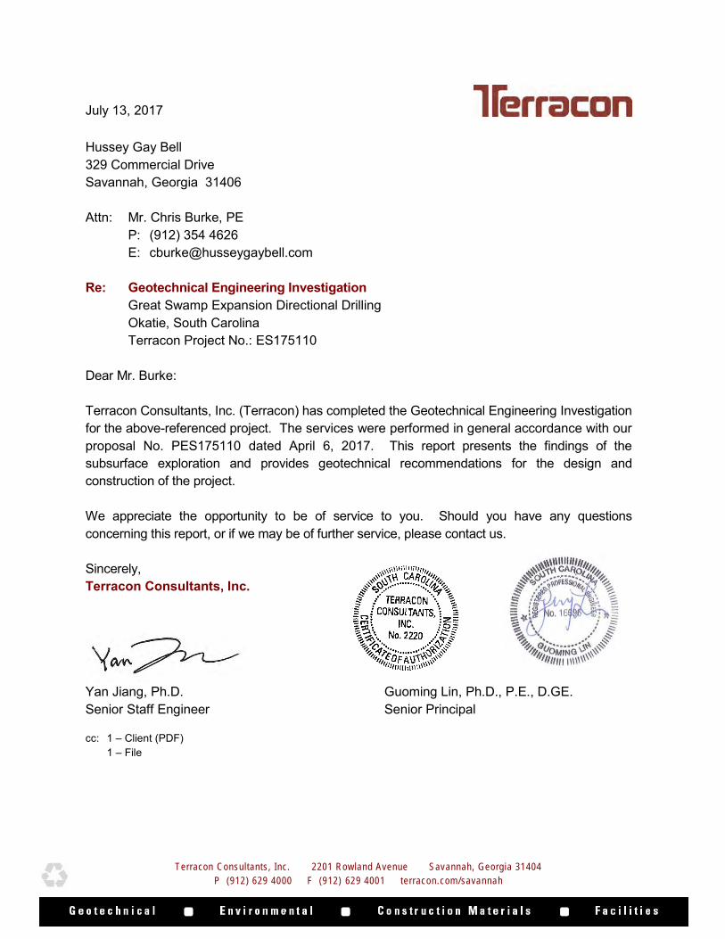
Terracon Consultants, Inc. 2201 Rowland Avenue Savannah, Georgia 31404
P (912) 629 4000 F (912) 629 4001 terracon.com/savannah
July 13, 2017 Hussey Gay Bell 329 Commercial Drive Savannah, Georgia 31406 Attn: Mr. Chris Burke, PE P: (912) 354 4626 E: [email protected] Re: Geotechnical Engineering Investigation Great Swamp Expansion Directional Drilling Okatie, South Carolina Terracon Project No.: ES175110 Dear Mr. Burke: Terracon Consultants, Inc. (Terracon) has completed the Geotechnical Engineering Investigation for the above-referenced project. The services were performed in general accordance with our proposal No. PES175110 dated April 6, 2017. This report presents the findings of the subsurface exploration and provides geotechnical recommendations for the design and construction of the project. We appreciate the opportunity to be of service to you. Should you have any questions concerning this report, or if we may be of further service, please contact us. Sincerely, Terracon Consultants, Inc. Yan Jiang, Ph.D. Guoming Lin, Ph.D., P.E., D.GE. Senior Staff Engineer Senior Principal cc: 1 – Client (PDF) 1 – File
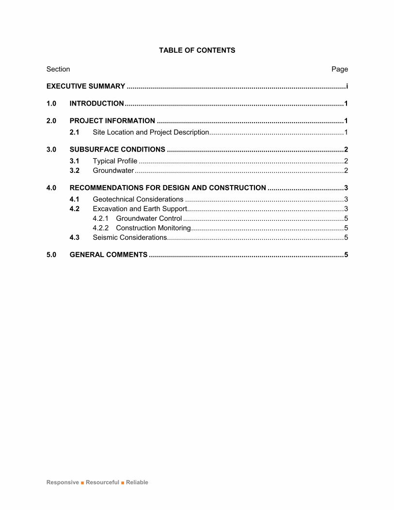
Responsive ■ Resourceful ■ Reliable
TABLE OF CONTENTS
Section Page
EXECUTIVE SUMMARY ............................................................................................................. i
1.0 INTRODUCTION ............................................................................................................. 1
2.0 PROJECT INFORMATION ............................................................................................. 1
2.1 Site Location and Project Description ................................................................... 1
3.0 SUBSURFACE CONDITIONS ........................................................................................ 2
3.1 Typical Profile ...................................................................................................... 2
3.2 Groundwater ........................................................................................................ 2
4.0 RECOMMENDATIONS FOR DESIGN AND CONSTRUCTION ...................................... 3
4.1 Geotechnical Considerations ............................................................................... 3
4.2 Excavation and Earth Support.............................................................................. 3
4.2.1 Groundwater Control ................................................................................ 5
4.2.2 Construction Monitoring ............................................................................ 5
4.3 Seismic Considerations........................................................................................ 5
5.0 GENERAL COMMENTS ................................................................................................. 5

Responsive ■ Resourceful ■ Reliable
APPENDICES
APPENDIX A: FIELD EXPLORATION
Exhibit A-1 Site Location Map Exhibit A-2 Exploration Location Plan Exhibit A-3 Field Exploration Description Exhibit A-4 SPT Boring Cross Section Exhibit A-5 SPT Boring Logs
APPENDIX B: SUPPORTING INFORMATION
Exhibit B-1 Seismic Design Parameters Exhibit B-2 General Notes Exhibit B-3 Unified Soil Classification System

Geotechnical Engineering Investigation Great Swamp Expansion Directional Drilling ■ Okatie, South Carolina July 13, 2017 ■ Terracon Project No. ES175110
Responsive ■ Resourceful ■ Reliable i
EXECUTIVE SUMMARY This report presents the findings of our Geotechnical Engineering Investigation for the proposed two directional drilling pits located north of Highway 278 in Okatie, South Carolina. The investigation included a field exploration program and engineering evaluation of the subsurface conditions and recommendations. Based on the results of the subsurface exploration and analyses, the following geotechnical considerations were identified:
In general, the soil profile at two boring locations are variable:
• For B1, the soils in the upper 17 feet are very loose to medium dense sands with clay underlain by very loose to medium dense sands to the depth of 32 feet below the existing ground surface (BGS). Below the layer of loose to medium dense sands is a layer of stiff to hard lean clay to the termination of SPT boring at the depth of 60 feet BGS.
• For B2, the soils in the upper 17 feet are very loose to medium dense sands with clay underlain by very loose to medium dense sands to the termination of SPT boring at the depth of 60 feet BGS.
The groundwater was encountered at approximately 6 to 8.5 feet BGS within the SPT borings immediately following drilling. The groundwater was checked 48 hours following drilling and a recent rain event and the water level was approximately 1 foot below the surface.
For seismic design purposes, Terracon classified the site as Site Class D in accordance with the ASCE 7-10 Section 11.4.2.
This summary should be used in conjunction with the entire report for design purposes. It should be recognized that details were not included or fully developed in this section, and the report must be read in its entirety for a comprehensive understanding of the findings and recommendations contained herein. The section titled GENERAL COMMENTS should be read for an understanding of the report’s limitations.

Responsive ■ Resourceful ■ Reliable 1
GEOTECHNICAL ENGINEERING INVESTIGATION
Great Swamp Expansion Directional Drilling Okatie, South Carolina
Terracon Project No. ES175110 July 13, 2017
1.0 INTRODUCTION Terracon has completed the Geotechnical Engineering Investigation for the proposed two directional drilling pits located north of Highway 278 in Okatie, South Carolina. The investigation included a field exploration program and engineering evaluation of the subsurface conditions and geotechnical recommendations. The field exploration program consisted of two (2) standard penetration test (SPT) borings to a maximum depth of 60 feet below the existing ground surface (BGS). The SPT boring logs along with a site location map and exploration location plan are included in Appendix A of this report. The purpose of this study is to provide subsurface information and geotechnical engineering recommendations relative to:
subsurface soil conditions groundwater conditions
excavation and earth support seismic considerations 2.0 PROJECT INFORMATION 2.1 Site Location and Project Description
Item Description
Location The site is located north of highway 278 in Okatie, South Carolina. Latitude: 32.3160°, Longitude: -80.9944°
Current ground cover The site is densely wooded.
Existing topography Relatively level.
Proposed improvements
The proposed project will include the construction of two directional drilling pits.
Grading It is anticipated that the site work will involve a deep excavation for the drill pits on either side of the directional drill alignment.
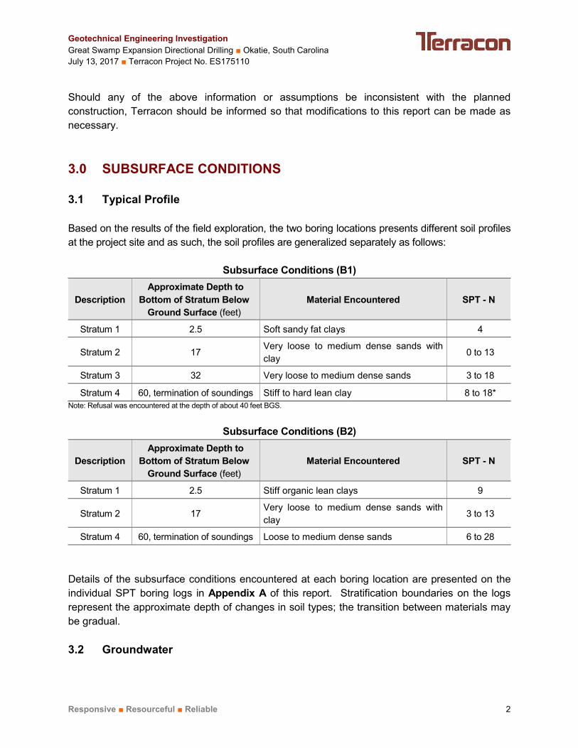
Geotechnical Engineering Investigation Great Swamp Expansion Directional Drilling ■ Okatie, South Carolina July 13, 2017 ■ Terracon Project No. ES175110
Responsive ■ Resourceful ■ Reliable 2
Should any of the above information or assumptions be inconsistent with the planned construction, Terracon should be informed so that modifications to this report can be made as necessary. 3.0 SUBSURFACE CONDITIONS 3.1 Typical Profile
Based on the results of the field exploration, the two boring locations presents different soil profiles at the project site and as such, the soil profiles are generalized separately as follows:
Subsurface Conditions (B1)
Description Approximate Depth to
Bottom of Stratum Below Ground Surface (feet)
Material Encountered SPT - N
Stratum 1 2.5 Soft sandy fat clays 4
Stratum 2 17 Very loose to medium dense sands with clay
0 to 13
Stratum 3 32 Very loose to medium dense sands 3 to 18
Stratum 4 60, termination of soundings Stiff to hard lean clay 8 to 18* Note: Refusal was encountered at the depth of about 40 feet BGS.
Subsurface Conditions (B2)
Description Approximate Depth to
Bottom of Stratum Below Ground Surface (feet)
Material Encountered SPT - N
Stratum 1 2.5 Stiff organic lean clays 9
Stratum 2 17 Very loose to medium dense sands with clay
3 to 13
Stratum 4 60, termination of soundings Loose to medium dense sands 6 to 28 Details of the subsurface conditions encountered at each boring location are presented on the individual SPT boring logs in Appendix A of this report. Stratification boundaries on the logs represent the approximate depth of changes in soil types; the transition between materials may be gradual. 3.2 Groundwater
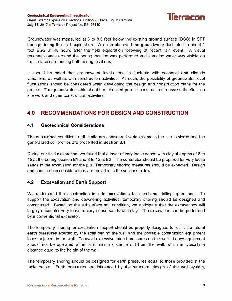
Geotechnical Engineering Investigation Great Swamp Expansion Directional Drilling ■ Okatie, South Carolina July 13, 2017 ■ Terracon Project No. ES175110
Responsive ■ Resourceful ■ Reliable 3
Groundwater was measured at 6 to 8.5 feet below the existing ground surface (BGS) in SPT borings during the field exploration. We also observed the groundwater fluctuated to about 1 foot BGS at 48 hours after the field exploration following at recent rain event. A visual reconnaissance around the boring location was performed and standing water was visible on the surface surrounding both boring locations. It should be noted that groundwater levels tend to fluctuate with seasonal and climatic variations, as well as with construction activities. As such, the possibility of groundwater level fluctuations should be considered when developing the design and construction plans for the project. The groundwater table should be checked prior to construction to assess its effect on site work and other construction activities. 4.0 RECOMMENDATIONS FOR DESIGN AND CONSTRUCTION 4.1 Geotechnical Considerations
The subsurface conditions at this site are considered variable across the site explored and the generalized soil profiles are presented in Section 3.1. During our field exploration, we found that a layer of very loose sands with clay at depths of 8 to 15 at the boring location B1 and 8 to 13 at B2. The contractor should be prepared for very loose sands in the excavation for the pits. Temporary shoring measures should be expected. Design and construction considerations are provided in the sections below. 4.2 Excavation and Earth Support
We understand the construction include excavations for directional drilling operations. To support the excavation and dewatering activities, temporary shoring should be designed and constructed. Based on the subsurface soil condition, we anticipate that the excavations will largely encounter very loose to very dense sands with clay. The excavation can be performed by a conventional excavator. The temporary shoring for excavation support should be properly designed to resist the lateral earth pressures exerted by the soils behind the wall and the possible construction equipment loads adjacent to the wall. To avoid excessive lateral pressures on the walls, heavy equipment should not be operated within a minimum distance out from the wall, which is typically a distance equal to the height of the wall. The temporary shoring should be designed for earth pressures equal to those provided in the table below. Earth pressures are influenced by the structural design of the wall system,

Geotechnical Engineering Investigation Great Swamp Expansion Directional Drilling ■ Okatie, South Carolina July 13, 2017 ■ Terracon Project No. ES175110
Responsive ■ Resourceful ■ Reliable 4
conditions of the wall restraint, construction methods. The deflection of retaining walls may have to be limited; thus, the walls for excavation support may have to be designed for the “at-rest” condition which assumes no wall movement. The recommended design lateral earth pressures provided in the table below do not include a factor of safety and do not provide hydrostatic pressures on the wall. Lateral Soil Pressure Coefficient for Temporary Wall Design for Excavation Support (B1)
Approximate Depth of
Bottom of Stratum (feet*)
Material Type Unit
Weight (pcf)
Active Earth
Pressure Coefficient
(ka)
At-Rest Earth
Pressure Coefficient
(ko)
Passive Earth
Pressure Coefficient
(kp)
2.5 Soft sandy fat clays 105 1.00 1.00 1.00
6 Medium dense sands 110 0.36 0.53 2.77
17 Very loose sand 100 0.49 0.66 2.00
27 Loose sand 100 0.41 0.58 2.46
32 Medium dense sands 110 0.36 0.53 2.77 60, termination
of borings Stiff to hard lean clays 105 1.00 1.00 1.00
*below the existing ground surface
Lateral Soil Pressure Coefficient for Temporary Wall Design for Excavation Support (B2)
Approximate Depth of
Bottom of Stratum (feet*)
Material Type Unit
Weight (pcf)
Active Earth
Pressure Coefficient
(ka)
At-Rest Earth
Pressure Coefficient
(ko)
Passive Earth
Pressure Coefficient
(kp)
2.5 Organic lean clays 105 1.00 1.00 1.00 60, termination
of borings Very loose to medium dense 105 0.36 0.53 2.77
*below the existing ground surface
The groundwater level in this area is very shallow and a dewatering is anticipated for the excavation. An open pumping (sumps, trenches, and pumps) and a well point system (well points) are commonly used methods for the excavation. The selection of the dewatering method depends on an excavation depth. The open pumping method is used in open excavation, which can handle a small amount of water inflow in a small area or relatively impermeable soil, and lower the groundwater table by a limited depth (mostly 5 feet or less); while a well point system is used in a deep excavation which are formed by multiple closely spaced wells and connected by pipes to a powerful pump. The well point system can lower a
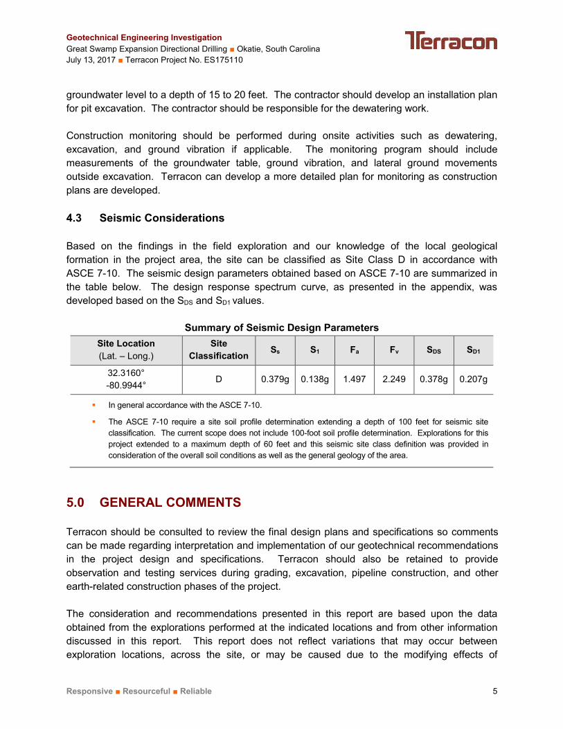
Geotechnical Engineering Investigation Great Swamp Expansion Directional Drilling ■ Okatie, South Carolina July 13, 2017 ■ Terracon Project No. ES175110
Responsive ■ Resourceful ■ Reliable 5
groundwater level to a depth of 15 to 20 feet. The contractor should develop an installation plan for pit excavation. The contractor should be responsible for the dewatering work. Construction monitoring should be performed during onsite activities such as dewatering, excavation, and ground vibration if applicable. The monitoring program should include measurements of the groundwater table, ground vibration, and lateral ground movements outside excavation. Terracon can develop a more detailed plan for monitoring as construction plans are developed. 4.3 Seismic Considerations
Based on the findings in the field exploration and our knowledge of the local geological formation in the project area, the site can be classified as Site Class D in accordance with ASCE 7-10. The seismic design parameters obtained based on ASCE 7-10 are summarized in the table below. The design response spectrum curve, as presented in the appendix, was developed based on the SDS and SD1 values.
Summary of Seismic Design Parameters Site Location (Lat. – Long.)
Site Classification Ss S1 Fa Fv SDS SD1
32.3160° -80.9944°
D 0.379g 0.138g 1.497 2.249 0.378g 0.207g
In general accordance with the ASCE 7-10.
The ASCE 7-10 require a site soil profile determination extending a depth of 100 feet for seismic site classification. The current scope does not include 100-foot soil profile determination. Explorations for this project extended to a maximum depth of 60 feet and this seismic site class definition was provided in consideration of the overall soil conditions as well as the general geology of the area.
5.0 GENERAL COMMENTS Terracon should be consulted to review the final design plans and specifications so comments can be made regarding interpretation and implementation of our geotechnical recommendations in the project design and specifications. Terracon should also be retained to provide observation and testing services during grading, excavation, pipeline construction, and other earth-related construction phases of the project. The consideration and recommendations presented in this report are based upon the data obtained from the explorations performed at the indicated locations and from other information discussed in this report. This report does not reflect variations that may occur between exploration locations, across the site, or may be caused due to the modifying effects of
Geotechnical Engineering Investigation Great Swamp Expansion Directional Drilling ■ Okatie, South Carolina July 13, 2017 ■ Terracon Project No. ES175110
Responsive ■ Resourceful ■ Reliable 6
construction or weather. Bear in mind that the nature and extent of such variations may not become evident until construction has started or until construction activities have ceased. If variations do appear, Terracon should be notified immediately so that further evaluation and supplemental recommendations can be provided. The scope of services for this project does not include either specifically or by implication any environmental or biological (e.g., mold, fungi, and bacteria) assessment of the site or identification or prevention of pollutants, hazardous materials or hazardous conditions. If the owner is concerned about the potential for such contamination or pollution, please advise so that additional studies may be undertaken. This report has been prepared for the exclusive use of our client for specific application to the project and site discussed, and has been prepared in accordance with generally accepted geotechnical engineering practices. No warranties, either expressed or implied, are intended or made. Site safety, excavation support and dewatering requirements are the responsibility of others. In the event that changes in the nature, design, or location of the project as outlined in this report are planned, the conclusions and recommendations contained in this report shall not be considered valid unless Terracon reviews the changes, and then either verifies or modifies the conclusions of this report in writing.

APPENDIX A FIELD EXPLORATION
Exhibit A-1 Site Location MapExhibit A-2 Exploration Location PlanExhibit A-3 Field Exploration DescriptionExhibit A-4 SPT Cross SectionExhibit A-5 SPT Logs

A-1
Exhibit:Project Manager:
Drawn by:
Checked by:
Approved by:
GL
GL
Project No.
Scale:
File Name:
Date:
ES175110
N.T.S.
5/16/17
SITE LOCATION MAP
SITE
2201 Rowland Avenue Savannah, Georgia 31404
Phone (912) 629 4000 Fax (912) 629 4001
N
YJ
Image Courtesy of
Google Earth™ YJ
Great Swamp Expansion Directional Drilling
Okatie, South Carolina

Exhibit:Project Manager:
Drawn by:
Checked by:
Approved by:
GL
GL
Project No.
Scale:
File Name:
Date:
ES175110
N.T.S.
5/16/17
EXPLORATION LOCATION PLAN
2201 Rowland Avenue Savannah, Georgia 31404
Phone (912) 629 4000 Fax (912) 629 4001
Great Swamp Expansion Directional Drilling
Okatie, South Carolina
YJ
YJ
A-2(1)
N
Image Courtesy of
Google Earth™
LEGEND
SPT Borings
NOTES:
ALL EXPLORATION LOCATIONS WERE LOCATED IN THE FIELD USING A
GPS UNIT AND / OR SITE LANDMARKS. EXPLORATION LOCATIONS
SHOULD BE CONSIDERED APPROXIMATE. DIAGRAM IS FOR GENERAL
LOCATION ONLY; NOT INTENDED FOR CONSTRUCTION PURPOSES.
B1
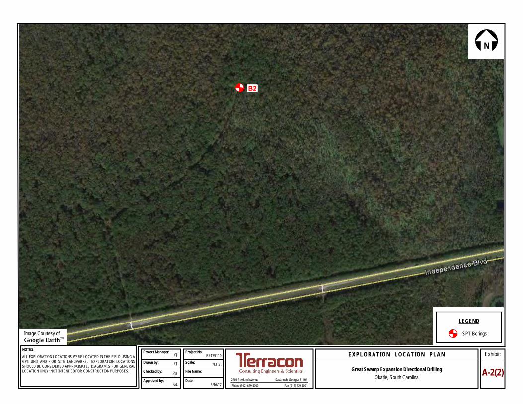
Exhibit:Project Manager:
Drawn by:
Checked by:
Approved by:
GL
GL
Project No.
Scale:
File Name:
Date:
ES175110
N.T.S.
5/16/17
EXPLORATION LOCATION PLAN
2201 Rowland Avenue Savannah, Georgia 31404
Phone (912) 629 4000 Fax (912) 629 4001
Great Swamp Expansion Directional Drilling
Okatie, South Carolina
YJ
YJ
A-2(2)
N
Image Courtesy of
Google Earth™
LEGEND
SPT Borings
NOTES:
ALL EXPLORATION LOCATIONS WERE LOCATED IN THE FIELD USING A
GPS UNIT AND / OR SITE LANDMARKS. EXPLORATION LOCATIONS
SHOULD BE CONSIDERED APPROXIMATE. DIAGRAM IS FOR GENERAL
LOCATION ONLY; NOT INTENDED FOR CONSTRUCTION PURPOSES.
B2

Geotechnical Engineering InvestigationGreat Swamp Expansion Directional Drilling ■ Okatie, South CarolinaJune 21, 2017 ■ Terracon Project No.ES175110
Responsive ■ Resourceful ■ Reliable Exhibit A-3
Field Exploration DescriptionThe locations of Standard Penetration Test (SPT) and hand auger borings are determined byTerracon based on the proposed plan and were located in the field using a hand-held GPS unit andin reference to the existing features. These locations are shown in the Exploration Location Plan inExhibit A-2 and should be considered approximate.
Standard Penetration TestingThe SPT borings were performed in accordance with ASTM D1586 with atrailer-mounted CME drilling rig using mud rotatory drilling techniques.Samples of the soil encountered in the borings were obtained using split-barrel sampling procedures. In the split barrel sampling procedure, thenumber of blows required to advance a standard 2-inch O.D. split barrelsampler the last 12 inches of the typical total 18-inch penetration by meansof a 140-pound hammer with a free fall of 30 inches, is the standardpenetration resistance value (SPT-N). This value is used to estimate thein situ relative density of cohesionless soils and consistency of cohesivesoils. A rope and cathead hammer was used to advance the split-barrelsampler in the borings performed on this site.
Source: FHWA NHI-06-088
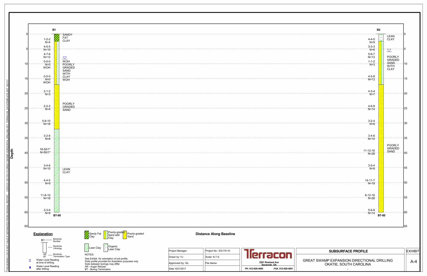
0
5
10
15
20
25
30
35
40
45
50
55
60
65
0
5
10
15
20
25
30
35
40
45
50
55
60
65
BT-60
1-2-2N=4
4-5-5N=104-7-6N=130-0-0N=0
WOH
0-0-0N=0
WOH
2-1-2N=3
2-2-2N=4
5-8-10N=18
3-2-6N=8
18-50/1"N=50/1"
3-4-6N=10
4-4-5N=9
11-8-10N=18
3-3-6N=9
SANDYFATCLAY
WOHPOORLYGRADEDSANDWITHCLAYWOH
POORLYGRADEDSAND
LEANCLAY
B1
BT-60
4-4-5N=9
3-3-3N=6
5-6-7N=131-1-2N=3
4-5-8N=13
4-3-4N=7
4-6-8N=14
3-2-4N=6
3-4-6N=10
11-12-16N=28
3-5-4N=9
14-11-7N=18
8-12-16N=28
5-6-8N=14
LEANCLAY
POORLYGRADEDSANDWITHCLAY
POORLYGRADEDSAND
B2
Water Level Readingafter drilling.
Water Level Readingat time of drilling.
B1
ARBT
BoreholeLithology
NOTES:
BoreholeNumber
BoreholeTermination Type
Explanation Distance Along Baseline
Dep
th
Sandy FatClay
Poorly-gradedSand withClay
Poorly-gradedSand
Lean Clay OrganicLean Clay
See Exhibit for orientation of soil profile.Soils profile provided for illustration purposes only.Soils between borings may differAR - Auger RefusalBT - Boring TerminationTH
IS B
OR
ING
LO
G IS
NO
T V
ALI
D IF
SE
PA
RA
TED
FR
OM
OR
IGIN
AL
RE
PO
RT.
C
OS
TCO
ES
1751
110
GR
EA
T S
WA
MP
HO
RIZ
ON
TAL
DR
ILLI
NG
.GP
J T
ER
RA
CO
N_D
ATA
TEM
PLA
TE.G
DT
6/2
1/17
2201 Rowland AveSavannah, GA
PH. 912-629-4000 FAX. 912-629-4001
SUBSURFACE PROFILE EXHIBIT
Approved by: GL
Project Manager:
GREAT SWAMP EXPANSION DIRECTIONAL DRILLINGOKATIE, SOUTH CAROLINA
,File Name:
Scale: N.T.S.
Project No.: ES175110
Drawn by: YJ
Date: 6/21/2017
A-4

1-2-2N=4
4-5-5N=10
4-7-6N=13
0-0-0N=0
WOH
0-0-0N=0
WOH
2-1-2N=3
2-2-2N=4
2.5
17.0
SANDY FAT CLAY (CH), dark brown and brown, soft
POORLY GRADED SAND WITH CLAY (SP-SC), fine grained, gray and light brown, medium dense
very loose
POORLY GRADED SAND (SP), fine grained, gray, very loose
loose
GR
APH
IC L
OG
Hammer Type: AutomaticStratification lines are approximate. In-situ, the transition may be gradual.
THIS
BO
RIN
G L
OG
IS N
OT
VAL
ID IF
SEP
ARAT
ED
FR
OM
OR
IGIN
AL
REP
OR
T.
GE
O S
MAR
T LO
G-N
O W
ELL
ES
1751
110
GR
EAT
SW
AMP
HO
RIZ
ON
TAL
DR
ILLI
NG
.GP
J T
ER
RA
CO
N_D
ATA
TEM
PLA
TE.G
DT
6/2
1/17
FIEL
D T
EST
RES
ULT
S
Okatie, South CarolinaSITE:
Page 1 of 3
Advancement Method:
Abandonment Method:
Notes:
Project No.: ES175110
Drill Rig: ATV CME 55
Boring Started: 6/7/2017
BORING LOG NO. B1Hussey Gay BellCLIENT:329 Commercial Drive
Driller: Corbett
Boring Completed: 6/7/2017
Exhibit:
Savannah, Georgia
A-5-1
See Exhibit A-3 for description of fieldprocedures.See Appendix B for description of laboratoryprocedures and additional data (if any).See Appendix C for explanation of symbols andabbreviations.
PROJECT: Great Swamp Expansion Directional Drilling
2201 Rowland AveSavannah, GA
While drilling
After 48 hours
WATER LEVEL OBSERVATIONS
DEPTH
LOCATION
Latitude: 32.326041° Longitude: -80.993746°
See Exhibit A-2
WA
TER
LEV
ELO
BS
ERVA
TIO
NS
DEP
TH (F
t.)
5
10
15
20
25
SA
MP
LE T
YP
E

5-8-10N=18
3-2-6N=8
18-50/1"
3-4-6N=10
4-4-5N=9
32.0
POORLY GRADED SAND (SP), fine grained, gray, very loose (continued)
medium dense
LEAN CLAY (CL), olive, stiff
hard
stiff
GR
APH
IC L
OG
Hammer Type: AutomaticStratification lines are approximate. In-situ, the transition may be gradual.
THIS
BO
RIN
G L
OG
IS N
OT
VAL
ID IF
SEP
ARAT
ED
FR
OM
OR
IGIN
AL
REP
OR
T.
GE
O S
MAR
T LO
G-N
O W
ELL
ES
1751
110
GR
EAT
SW
AMP
HO
RIZ
ON
TAL
DR
ILLI
NG
.GP
J T
ER
RA
CO
N_D
ATA
TEM
PLA
TE.G
DT
6/2
1/17
FIEL
D T
EST
RES
ULT
S
Okatie, South CarolinaSITE:
Page 2 of 3
Advancement Method:
Abandonment Method:
Notes:
Project No.: ES175110
Drill Rig: ATV CME 55
Boring Started: 6/7/2017
BORING LOG NO. B1Hussey Gay BellCLIENT:329 Commercial Drive
Driller: Corbett
Boring Completed: 6/7/2017
Exhibit:
Savannah, Georgia
A-5-1
See Exhibit A-3 for description of fieldprocedures.See Appendix B for description of laboratoryprocedures and additional data (if any).See Appendix C for explanation of symbols andabbreviations.
PROJECT: Great Swamp Expansion Directional Drilling
2201 Rowland AveSavannah, GA
While drilling
After 48 hours
WATER LEVEL OBSERVATIONS
DEPTH
LOCATION
Latitude: 32.326041° Longitude: -80.993746°
See Exhibit A-2
WA
TER
LEV
ELO
BS
ERVA
TIO
NS
DEP
TH (F
t.)
30
35
40
45
50
SA
MP
LE T
YP
E

11-8-10N=18
3-3-6N=9
60.0
LEAN CLAY (CL), olive, stiff (continued)
very stiff
stiff
Boring Terminated at 60 Feet
GR
APH
IC L
OG
Hammer Type: AutomaticStratification lines are approximate. In-situ, the transition may be gradual.
THIS
BO
RIN
G L
OG
IS N
OT
VAL
ID IF
SEP
ARAT
ED
FR
OM
OR
IGIN
AL
REP
OR
T.
GE
O S
MAR
T LO
G-N
O W
ELL
ES
1751
110
GR
EAT
SW
AMP
HO
RIZ
ON
TAL
DR
ILLI
NG
.GP
J T
ER
RA
CO
N_D
ATA
TEM
PLA
TE.G
DT
6/2
1/17
FIEL
D T
EST
RES
ULT
S
Okatie, South CarolinaSITE:
Page 3 of 3
Advancement Method:
Abandonment Method:
Notes:
Project No.: ES175110
Drill Rig: ATV CME 55
Boring Started: 6/7/2017
BORING LOG NO. B1Hussey Gay BellCLIENT:329 Commercial Drive
Driller: Corbett
Boring Completed: 6/7/2017
Exhibit:
Savannah, Georgia
A-5-1
See Exhibit A-3 for description of fieldprocedures.See Appendix B for description of laboratoryprocedures and additional data (if any).See Appendix C for explanation of symbols andabbreviations.
PROJECT: Great Swamp Expansion Directional Drilling
2201 Rowland AveSavannah, GA
While drilling
After 48 hours
WATER LEVEL OBSERVATIONS
DEPTH
LOCATION
Latitude: 32.326041° Longitude: -80.993746°
See Exhibit A-2
WA
TER
LEV
ELO
BS
ERVA
TIO
NS
DEP
TH (F
t.)
55
60
SA
MP
LE T
YP
E

4-4-5N=9
3-3-3N=6
5-6-7N=13
1-1-2N=3
4-5-8N=13
4-3-4N=7
4-6-8N=14
2.5
17.0
LEAN CLAY (OL), trace gravel, dark brown, stiff
POORLY GRADED SAND WITH CLAY (SP-SC), fine grained, brown, loose
brown and gray, medium dense
very loose
medium dense
POORLY GRADED SAND (SP), fine grained, gray, loose
medium dense
GR
APH
IC L
OG
Hammer Type: AutomaticStratification lines are approximate. In-situ, the transition may be gradual.
THIS
BO
RIN
G L
OG
IS N
OT
VAL
ID IF
SEP
ARAT
ED
FR
OM
OR
IGIN
AL
REP
OR
T.
GE
O S
MAR
T LO
G-N
O W
ELL
ES
1751
110
GR
EAT
SW
AMP
HO
RIZ
ON
TAL
DR
ILLI
NG
.GP
J T
ER
RA
CO
N_D
ATA
TEM
PLA
TE.G
DT
6/2
1/17
FIEL
D T
EST
RES
ULT
S
Okatie, South CarolinaSITE:
Page 1 of 3
Advancement Method:
Abandonment Method:
Notes:
Project No.: ES175110
Drill Rig: ATV CME 55
Boring Started: 6/7/2017
BORING LOG NO. B2Hussey Gay BellCLIENT:329 Commercial Drive
Driller: Corbett
Boring Completed: 6/7/2017
Exhibit:
Savannah, Georgia
A-5-2
See Exhibit A-3 for description of fieldprocedures.See Appendix B for description of laboratoryprocedures and additional data (if any).See Appendix C for explanation of symbols andabbreviations.
PROJECT: Great Swamp Expansion Directional Drilling
2201 Rowland AveSavannah, GA
While drilling
After 48 hours
WATER LEVEL OBSERVATIONS
DEPTH
LOCATION
Latitude: 32.314735° Longitude: -80.995197°
See Exhibit A-2
WA
TER
LEV
ELO
BS
ERVA
TIO
NS
DEP
TH (F
t.)
5
10
15
20
25
SA
MP
LE T
YP
E
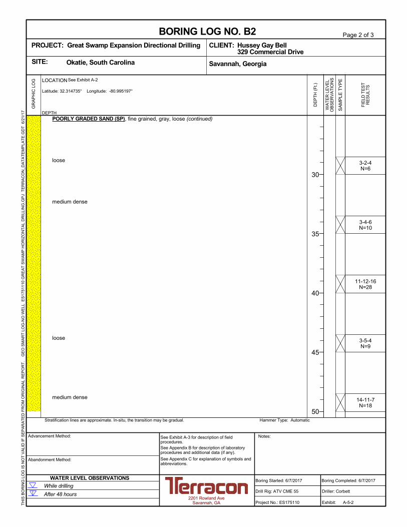
3-2-4N=6
3-4-6N=10
11-12-16N=28
3-5-4N=9
14-11-7N=18
POORLY GRADED SAND (SP), fine grained, gray, loose (continued)
loose
medium dense
loose
medium dense
GR
APH
IC L
OG
Hammer Type: AutomaticStratification lines are approximate. In-situ, the transition may be gradual.
THIS
BO
RIN
G L
OG
IS N
OT
VAL
ID IF
SEP
ARAT
ED
FR
OM
OR
IGIN
AL
REP
OR
T.
GE
O S
MAR
T LO
G-N
O W
ELL
ES
1751
110
GR
EAT
SW
AMP
HO
RIZ
ON
TAL
DR
ILLI
NG
.GP
J T
ER
RA
CO
N_D
ATA
TEM
PLA
TE.G
DT
6/2
1/17
FIEL
D T
EST
RES
ULT
S
Okatie, South CarolinaSITE:
Page 2 of 3
Advancement Method:
Abandonment Method:
Notes:
Project No.: ES175110
Drill Rig: ATV CME 55
Boring Started: 6/7/2017
BORING LOG NO. B2Hussey Gay BellCLIENT:329 Commercial Drive
Driller: Corbett
Boring Completed: 6/7/2017
Exhibit:
Savannah, Georgia
A-5-2
See Exhibit A-3 for description of fieldprocedures.See Appendix B for description of laboratoryprocedures and additional data (if any).See Appendix C for explanation of symbols andabbreviations.
PROJECT: Great Swamp Expansion Directional Drilling
2201 Rowland AveSavannah, GA
While drilling
After 48 hours
WATER LEVEL OBSERVATIONS
DEPTH
LOCATION
Latitude: 32.314735° Longitude: -80.995197°
See Exhibit A-2
WA
TER
LEV
ELO
BS
ERVA
TIO
NS
DEP
TH (F
t.)
30
35
40
45
50
SA
MP
LE T
YP
E
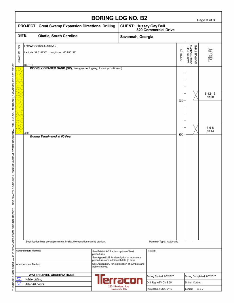
8-12-16N=28
5-6-8N=14
60.0
POORLY GRADED SAND (SP), fine grained, gray, loose (continued)
Boring Terminated at 60 Feet
GR
APH
IC L
OG
Hammer Type: AutomaticStratification lines are approximate. In-situ, the transition may be gradual.
THIS
BO
RIN
G L
OG
IS N
OT
VAL
ID IF
SEP
ARAT
ED
FR
OM
OR
IGIN
AL
REP
OR
T.
GE
O S
MAR
T LO
G-N
O W
ELL
ES
1751
110
GR
EAT
SW
AMP
HO
RIZ
ON
TAL
DR
ILLI
NG
.GP
J T
ER
RA
CO
N_D
ATA
TEM
PLA
TE.G
DT
6/2
1/17
FIEL
D T
EST
RES
ULT
S
Okatie, South CarolinaSITE:
Page 3 of 3
Advancement Method:
Abandonment Method:
Notes:
Project No.: ES175110
Drill Rig: ATV CME 55
Boring Started: 6/7/2017
BORING LOG NO. B2Hussey Gay BellCLIENT:329 Commercial Drive
Driller: Corbett
Boring Completed: 6/7/2017
Exhibit:
Savannah, Georgia
A-5-2
See Exhibit A-3 for description of fieldprocedures.See Appendix B for description of laboratoryprocedures and additional data (if any).See Appendix C for explanation of symbols andabbreviations.
PROJECT: Great Swamp Expansion Directional Drilling
2201 Rowland AveSavannah, GA
While drilling
After 48 hours
WATER LEVEL OBSERVATIONS
DEPTH
LOCATION
Latitude: 32.314735° Longitude: -80.995197°
See Exhibit A-2
WA
TER
LEV
ELO
BS
ERVA
TIO
NS
DEP
TH (F
t.)
55
60
SA
MP
LE T
YP
E

APPENDIX B SUPPORTING INFORMATION
Exhibit B-1 Seismic Design ParametersExhibit B-2 General NotesExhibit B-3 Unified Soil Classification System
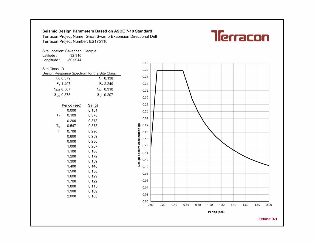
Seismic Design Parameters Based on ASCE 7-10 StandardTerracon Project Name: Great Swamp Exapnsion Directional DrillTerracon Project Number: ES175110
Site Location: Savannah, GeorgiaLatitude : 32.316Longitude : -80.9944
Site Class: DDesign Response Spectrum for the Site Class
Ss 0.379 S1 0.138Fa 1.497 Fv 2.249
SMS 0.567 SM1 0.310SDS 0.378 SD1 0.207
Period (sec) Sa (g)0.000 0.151
T0 0.109 0.3780.200 0.378
TS 0.547 0.378T 0.700 0.296
0.800 0.2590.900 0.2301.000 0.2071.100 0.1881.200 0.1721.300 0.1591.400 0.1481.500 0.1381.600 0.1291.700 0.1221.800 0.1151.900 0.1092.000 0.103
Exhibit B-1
0.00
0.02
0.04
0.06
0.08
0.10
0.12
0.14
0.16
0.18
0.20
0.22
0.24
0.26
0.28
0.30
0.32
0.34
0.36
0.38
0.40
0.00 0.20 0.40 0.60 0.80 1.00 1.20 1.40 1.60 1.80 2.00
Des
ign
Spec
tra
Acce
lera
tion
(g)
Period (sec)
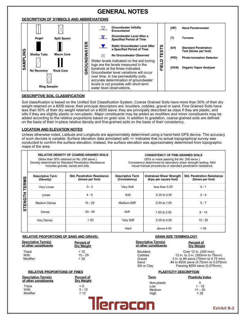
Ring Sampler
SAM
PLIN
G
GR
OU
ND
WA
TER
Groundwater InitiallyEncountered
(More than 50% retained on No. 200 sieve.)Density determined by Standard Penetration Resistance
Includes gravels, sands and silts.
BouldersCobblesGravelSandSilt or Clay
Split SpoonAuger
No Recovery Rock Core
Shelby Tube Macro Core
FIEL
D T
ESTS
PLASTICITY DESCRIPTIONTerm
Hand Penetrometer
Torvane
Standard PenetrationTest (blows per foot)
Photo-Ionization Detector
Organic Vapor Analyzer
Groundwater Level After aSpecified Period of Time
Static Groundwater Level Aftera Specified Period of Time
Unless otherwise noted, Latitude and Longitude are approximately determined using a hand-held GPS device. The accuracyof such devices is variable. Surface elevation data annotated with +/- indicates that no actual topographical survey wasconducted to confirm the surface elevation. Instead, the surface elevation was approximately determined from topographicmaps of the area.
Non-plasticLowMediumHigh
Soil classification is based on the Unified Soil Classification System. Coarse Grained Soils have more than 50% of their dryweight retained on a #200 sieve; their principal descriptors are: boulders, cobbles, gravel or sand. Fine Grained Soils haveless than 50% of their dry weight retained on a #200 sieve; they are principally described as clays if they are plastic, andsilts if they are slightly plastic or non-plastic. Major constituents may be added as modifiers and minor constituents may beadded according to the relative proportions based on grain size. In addition to gradation, coarse-grained soils are definedon the basis of their in-place relative density and fine-grained soils on the basis of their consistency.
Plasticity Index0
1 - 1011 - 30
> 30
RELATIVE PROPORTIONS OF FINESDescriptive Term(s)of other constituents
Percent ofDry Weight
< 55 - 12> 12
TraceWithModifier
GRAIN SIZE TERMINOLOGYRELATIVE PROPORTIONS OF SAND AND GRAVEL
Hard
TraceWithModifier
> 30above 4.00
2.00 to 4.00
1.00 to 2.00
0.50 to 1.00
0.25 to 0.50
less than 0.25
(50% or more passing the No. 200 sieve.)Consistency determined by laboratory shear strength testing, field
visual-manual procedures or standard penetration resistance
CONSISTENCY OF FINE-GRAINED SOILS
Very Loose
Loose
Medium Dense
Dense
Descriptive Term(Density)
> 50
30 - 50
10 - 29
4 - 9
0 - 3
STEN
GTH
TER
MS Std. Penetration Resistance
(blows per foot)
Very Stiff
Stiff
RELATIVE DENSITY OF COARSE-GRAINED SOILS
15 - 30
8 - 14
Medium-Stiff
Soft
Very Soft
Descriptive Term(Consistency)
2 - 4
0 - 1
Std. Penetration Resistance(blows per foot)
Undrained Shear Strength(kips per square foot)
Very Dense
5 - 7
Over 12 in. (300 mm)12 in. to 3 in. (300mm to 75mm)
3 in. to #4 sieve (75mm to 4.75 mm)#4 to #200 sieve (4.75mm to 0.075mm
Passing #200 sieve (0.075mm)
< 1515 - 29> 30
Descriptive Term(s)of other constituents
Percent ofDry Weight
Descriptive Term(s)of other constituents
Percent ofDry Weight
No Groundwater Observed
GENERAL NOTES
LOCATION AND ELEVATION NOTES
(HP)
(T)
(b/f)
(PID)
(OVA)
Water levels indicated on the soil boringlogs are the levels measured in theborehole at the times indicated.Groundwater level variations will occurover time. In low permeability soils,accurate determination of groundwaterlevels is not possible with short termwater level observations.
DESCRIPTION OF SYMBOLS AND ABBREVIATIONS
DESCRIPTIVE SOIL CLASSIFICATION
Exhibit B-2
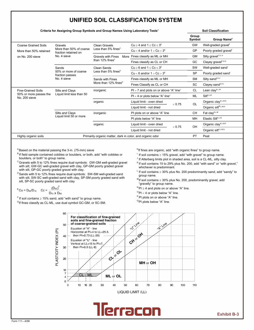
Form 111—6/98
UNIFIED SOIL CLASSIFICATION SYSTEM Criteria for Assigning Group Symbols and Group Names Using Laboratory TestsA Soil Classification
Group Symbol
Group NameB
Coarse Grained Soils
More than 50% retained
on No. 200 sieve
Gravels More than 50% of coarse fraction retained on No. 4 sieve
Clean Gravels Less than 5% finesC
Cu 4 and 1 Cc 3E GW Well-graded gravelF
Cu 4 and/or 1 Cc 3E GP Poorly graded gravelF
Gravels with Fines More than 12% finesC
Fines classify as ML or MH GM Silty gravelF,G, H
Fines classify as CL or CH GC Clayey gravelF,G,H
Sands 50% or more of coarse fraction passes No. 4 sieve
Clean Sands Less than 5% finesD
Cu 6 and 1 Cc 3E SW Well-graded sandI
Cu 6 and/or 1 Cc 3E SP Poorly graded sandI
Sands with Fines More than 12% finesD
Fines classify as ML or MH SM Silty sandG,H,I
Fines Classify as CL or CH SC Clayey sandG,H,I
Fine-Grained Soils 50% or more passes the No. 200 sieve
Silts and Clays Liquid limit less than 50
inorganic PI 7 and plots on or above “A” lineJ CL Lean clayK,L,M
PI 4 or plots below “A” lineJ ML SiltK,L,M
organic Liquid limit - oven dried 0.75 OL
Organic clayK,L,M,N
Liquid limit - not dried Organic siltK,L,M,O
Silts and Clays Liquid limit 50 or more
inorganic PI plots on or above “A” line CH Fat clayK,L,M
PI plots below “A” line MH Elastic SiltK,L,M
organic Liquid limit - oven dried 0.75 OH
Organic clayK,L,M,P
Liquid limit - not dried Organic siltK,L,M,Q
Highly organic soils Primarily organic matter, dark in color, and organic odor PT Peat
A Based on the material passing the 3-in. (75-mm) sieve B If field sample contained cobbles or boulders, or both, add “with cobbles or
boulders, or both” to group name. C Gravels with 5 to 12% fines require dual symbols: GW-GM well-graded gravel
with silt, GW-GC well-graded gravel with clay, GP-GM poorly graded gravel with silt, GP-GC poorly graded gravel with clay.
D Sands with 5 to 12% fines require dual symbols: SW-SM well-graded sand with silt, SW-SC well-graded sand with clay, SP-SM poorly graded sand with silt, SP-SC poorly graded sand with clay
E Cu = D60/D10 Cc = 6010
230
DxD)(D
F If soil contains 15% sand, add “with sand” to group name. G If fines classify as CL-ML, use dual symbol GC-GM, or SC-SM.
HIf fines are organic, add “with organic fines” to group name. I If soil contains 15% gravel, add “with gravel” to group name. J If Atterberg limits plot in shaded area, soil is a CL-ML, silty clay. K If soil contains 15 to 29% plus No. 200, add “with sand” or “with gravel,”
whichever is predominant. L If soil contains 30% plus No. 200 predominantly sand, add “sandy” to
group name. M If soil contains 30% plus No. 200, predominantly gravel, add
“gravelly” to group name. N PI 4 and plots on or above “A” line. O PI 4 or plots below “A” line. P PI plots on or above “A” line. Q PI plots below “A” line.
Exhibit B-3
APPENDIX B
MR SYSTEMS QUOTE - SCADA

MR Quote #:Q17-4852, EST Rev. 2
Bill of Materials and Labor
Qty Description
1 RTU-GS Mission M112 Wireless Alarm SystemEnclosure: Outdoor NEMA 4X Enclosure with Front Sun ShieldEnclosure Size: 13.75" H x 13.25" W x 6.25" D Options:
1 Service Package, #SP110-121 Analog Output Board, #OP4601 Service Package Option Board, #SPOP-12
Includes one-year warranty.
1 FE 16" Rosemount Magnetic FlowmeterFIT Model: Rosemount 8750WD
Transmitter Class: MW = Wall Mounting Transmitter, Remote Outdoor Mounted Transmitter Power Supply: 1 = AC Transmitter Options: A = 4 to 20 mA, HART Protocol Conduit Entry: 1 = 1/2"-14 Tube Style: F = Flanged Tube Lining: P = Polyurethane Tube Electrode Material: S = 316L Stainless Steel Tube Electrode Type: A = 2 Electrodes, Standard Tube Line Size: 160 = 16.0" Tube Flange Material: C = Carbon Steel Tube Flange Rating: A1 = Class 150 Safety Approvals: Blank = FM Non-hazardous Approval Safety Approvals: Blank = Non-Hazardous Area Plant Web Advanced Diagnostics: DA1 = HART Diagnostics Suite Transmitter Display Option: M4 = Local Operator Interface, LOI Tube Ground Ring Option: G1 = Pair, #316 Stainless Steel Calibration Certificate: Q4 = Supplied with instrument. Full Submergence Rating (IP68): R05 = For submergence of up to 30 ft. Includes 50 ft. of cable.Options:
1 Aluminum Solar Hood for Flowmeter Transmitter2 Nametags: One (1) Engraved SST1 Phoenix Contact AC Power & Analog, BOXTRAB
1 PIT Rosemount 3051CG Pressure Indicating Transmitter2 Nametags: One (1) Engraved SST1 Field-mounted "Pipe Bomb" Style Analog Surge Protector
0 Note: Modulating valve with 4 to 20 mA position input capability is to be supplied by Others; Not by MR Systems.
Project: Great Swamp EMS ExpansionCustomer: BJWSA
Tag/Loop
July 17, 2018
www.mrsystems.com1185 Beaver Ruin Rd • Norcross, GA 30093 • 678-325-2800
Page 1 of 3

MR Quote #:Q17-4852, EST Rev. 2
Bill of Materials and Labor
Qty Description
Project: Great Swamp EMS ExpansionCustomer: BJWSA
Tag/Loop
July 17, 2018
Project LaborOne Lot Project Engineering, Electrical Design, Mechanical Design, Drafting & Administrative Labor
(including Travel & Living expenses) as required to perform final system design and to prepare Submittals and Record Drawings as required by the Contract Documents.
One Lot HMI Software Applications Development & Graphics Design Labor (including Travel & Living expenses) as required by the Contract Documents.
One Lot PLC Control Strategy Design & Programming Labor (including Travel & Living expenses) to be performed as required by the Contract Documents.
One Lot Field Service (including Travel & Living expenses) to provide installation supervision calibrations, startup, training, etc. as required by the Contract Documents.
N/A Electrical Installation or Terminations (including Travel & Living expenses) to provide installation of conduit, wire, etc. as required by the Contract Documents.
1 Year Onsite Comprehensive Warranty (including Travel & Living expenses)
One Lot Freight
Subtotal of Labor and Materials: $23,810
State Sales Tax - NOT INCLUDED: $
Total Project Cost: $23,810
General Notes: A
B
Mr. Dave Johnson, P.E., of Heyward, Inc. in Charlotte, NC, is our local sales representative. Dave may be reached at 704-583-2305 (Office) or 803-920-6209 (Cell)
* Sales Representation *
* Technical Questions *For technical or scope of supply questions contact Tom Hopkins of MR Systems, Inc. Tom may be reached at 678-325-2829 (Office) or 770-519-1299 (Cell).
www.mrsystems.com1185 Beaver Ruin Rd • Norcross, GA 30093 • 678-325-2800
Page 2 of 3

MR Quote #:Q17-4852, EST Rev. 2
Bill of Materials and Labor
Qty Description
Project: Great Swamp EMS ExpansionCustomer: BJWSA
Tag/Loop
July 17, 2018
C
D
E
F
G
H
I
J
K
L
https://www.mrsystems.com/sellersterms/
Revision Notes:Rev. 0 EST ESTIMATE OF PROBABLE CONSTRUCTION COSTS - 2017-12-12 - THHRev. 1 EST Revised to use 4RF radio instead of MDS radio - 2018-05-07 - THHRev. 2 EST Deleted PLC-based RTU and added Mission M110 Cellular Autodialer - 2018-07-17
* Professional Engineering Authorization *As required by the South Carolina Board of Labor, Licensing and Regulation, System Integrators are required to hold a Certificate of Authorization to practice professional engineering in order to perform system integration. MR Systems' Certificate of Authorization Number is C01888.
* Terms and Conditions *MR Systems, Inc. General Terms & Conditions of Sale apply to any order resulting from this quotation. Please refer to the link provided below for a copy of our General Terms and Conditions of Sale.
* Fiber Optic Cable Termination *
* Equipment Installation *
This quotation DOES NOT INCLUDE termination or testing of fiber optics cable.
MR Systems' South Carolina Electrical Contractor's License Number is M108855, EL5 (Unlimited).
This quotation DOES NOT INCLUDE physical installation of field instruments, pipe, tubing, fittings, isolation valves, instrument stands, instrument mounts, control panels, antennas, masts, wooden poles, or other devices or other equipment unless specifically noted above.
* Contractor License Information *
* Wiring Terminations *
* Coaxial Cable Installation *
This quotation DOES NOT INCLUDE the supply or physical installation of Communication Towers or Poles.
This quotation DOES NOT INCLUDE the supply or physical installation of conduit or wire unless specifically noted above.
* Installation of Conduit and Wire *
This quotation INCLUDES the termination of field wiring to field instruments, control panels, RTU panels, and/or other devices supplied under this scope of supply. Terminations of wiring to equipment supplied by Others are
* Fiber Optics Cable *This quotation DOES NOT INCLUDE the supply or physical installation of Fiber Optic Cable.
This quotation INCLUDES the supply and physical installation of coaxial cable and ancillary components for the "whip" cellular antenna as specifically noted above.
* Installation of Communications Towers or Poles *
www.mrsystems.com1185 Beaver Ruin Rd • Norcross, GA 30093 • 678-325-2800
Page 3 of 3