issue 4, april 2007 - microchip technologyww1.microchip.com/downloads/en/market_communication/3v...
TRANSCRIPT

Issue 4, April 2007
IntroductionStephen CaldwellDirector, Home Appliance Solutions Group
Welcome to fourth issue of the 3V Newsletter created by theApplication Engineering community at Microchip Technology.This exciting series of newsletters is designed to cover thetechnical and logistical challenges of migrating designs from5V to 3V. In previous editions, we discussed the business case formoving to 3V only products. We touched upon some of thetechnical advantages that 3V products can offer. We providedhints on creating basic 3V power supplies, designing withmultiple power rails and how to interface 5V and 3V products.This issue covers several interesting topics. One articledispels the myth that 3V products are inherently not robust.Several articles discuss features in new products that wereenabled by the 3V technology. Finally, there are articles on 3Vsystem design – selecting LDOs and new 3V developmentboards.Future 3V Newsletters will cover more topics such as powersupplies, analog, communications, and power drivers. Thisseries of newsletters will also inform the reader of newapplication notes, migration documents, and web resourceapplicable on this topic.
For the latest information, make sure to visit www.microchip.com/3volts.If you have comments or suggestions for an article, pleasesend an e-mail to [email protected] can also help you select the device and tool that is rightfor you, and help you with a number of different technicalchallenges. Submit a ticket to support.microchip.com to getyour questions answered. Enjoy!
In This IssueNew 3V PIC18 Products in J-Series Portfolio ................... 2The Truth About Microchip’s J-Series Flash Performance 3Motor Control in a Distributed Intelligence System ........... 5dsPIC33F Motor Control Demo Boards ............................ 6Microchip’s Newest LDOs Extend Support of Low-Voltage Application Solutions......................................................... 7
© 2007 Microchip Technology Inc. 1
The simplest and most desired way to connect a 3.3V outputto a 5V input is by a direct connection. This can be done onlyif the following 2 requirements are met:• The VOH of the 3.3V output is greater than the VIH of the 5V
input• The VOL of the 3.3V output is less than the VIL of the 5V
inputAn example of when this technique can be used is interfacinga 3.3V LVCMOS output to a 5V TTL input. From the valuesgiven in Table 1, it can clearly be seen that both of theserequirements are met.3.3V LVCMOS VOH of 3.0 volts is greater than 5V TTL VIH of2.0 voltsand3.3V LVCMOS VOL of 0.5 volts is less than 5V TTL VIL of 0.8volts.When both of these requirements are not met, some addi-tional circuitry will be needed to interface the two parts. Youcan refer to Tips 6, 7, 8 and 13 in the Microchip 3V Tips ‘nTricks book (DS41285) for possible solutions.
Tip #5 3.3V 5V Direct ConnectDigital InterfacingWhen interfacing two devices that operate at different volt-ages, it is imperative to know the output and input thresholdsof both devices. Once these values are known, a techniquecan be selected for interfacing the devices based on the otherrequirements of your application. Table 1 contains the outputand input thresholds that will be used throughout theMicrochip 3V Tips ‘n Tricks book (DS41285). When designingan interface, make sure to reference your manufacturers datasheet for the actual threshold levels.TABLE 1: INPUT/OUTPUT THRESHOLDS
VOH min VOL max VIH min VIL max5V TTL 2.4V 0.5V 2.0V 0.8V
3.3V LVTTL 2.4V 0.4V 2.0V 0.8V5V CMOS 4.7V
(VCC-0.3V)0.5V 3.5V
(0.7xVCC)1.5V
(0.3xVCC)3.3V LVCMOS 3.0V
(VCC-0.3V)0.5V 2.3V
(0.7xVCC)1.0V
(0.3xVCC)

3V Newsletter
New 3V PIC18 Products in J-Series PortfolioAlexis AlcottPrincipal Marketing Engineer, AMADThe PIC18 J-series products are high-performance 8-bitmicrocontrollers with high levels of integration at 3V forcost sensitive applications.
Microchip’s 3V PIC18 J-series products include thePIC18F45J10 and PIC18F87J10 families. The newPIC18F87J11 family was recently introduced to expandthis J-series portfolio. The PIC18F87J11 familyincludes 64 and 80-pin devices with a robust peripheralset, ranging from 64 kB to 128 kB program Flash.
FIGURE 1:
The PIC18F87J11 offers a direct migration forPIC18F87J10 customers who want additional perfor-mance, lower power in Sleep mode, higher Flash
retention or a parallel master port. Compared to thePIC18F87J10, the PIC18F87J11 provides anenhanced peripheral set and performance including:• Lower power in Sleep mode for battery applica-
tions, as low as 0.1 uA in Sleep mode• Integrated 8 MHz internal oscillator with 4x PLL
for 32 MHz without external clock source• Higher performance: up to 12 MIPS, 48 MHz at 3
volts• Improved Flash characteristics: 10k endurance
(min.) and word write capability for easier EEPROM emulation
• Parallel Master Port for connection to parallel interfaces such as driving a large display or con-necting to a large external data memory
The robust peripheral set on the PIC18F87J11 familyincludes self-programming Flash with 10,000 re-writeendurance and 20 years minimum retention. Thisfamily also has standard embedded control peripheralsincluding ADC, Capture/Compare/PWM, timers,UARTs, I2C™ and SPI for communication. The PIC18J-series microcontrollers open the PIC18 into new costcompetitive markets due to their aggressive pricing.Table 1 is showing the differences between theperformance and Flash characteristics of the PIC18 Jfamilies.Three other PIC18 J families have also beenannounced and will be available soon: PIC18F85J11 general purpose, cost effective;PIC18F87J50 Full Speed USB 2.0; PIC18F85J90integrated LCD.As described in Issue #3, it is easy to evaluate thePIC18 J-series devices using the HPC Explorer Boardwith J-series 3V Plug-in modules. For more informationand discounted J-series development tools go towww.microchip.com/PIC18J.
TABLE 1:
Feature PIC18FXXJ10 and PIC18F97J60
PIC18F85J11 and PIC18F85J90
PIC18F87J11 and PIC18F87J50
Max. Speed (MHz) 40 40 48MIPS 10 10 12Program Flash (KB) 16-128 8-32 32-128Flash Erase Write Cycles 1K (typ) 1K (typ) 10K (min.)Flash Retention (min.) 20 years 20 years 20 yearsSelf-Write √ √ √
EEPROM Emulation √ √ √
Improved EEPROM Emulation word writeTypical Sleep Current (uA) Reg Off 43 0.1 0.1Typical Sleep Current (uA) Reg On 100 3 3Voltage Range 2.0 to 3.6 2.0 to 3.6 2.0 to 3.65V tolerant I/O √ √ √
Internal Oscillator 31 kHz 8 MHz and 32 kHz 8 MHz and 31 kHzInt Osc + PLL (max. freq.) ext only ext only up to 32 MHzE-Temp Options √
2 © 2007 Microchip Technology Inc.
3V Newsletter
The Truth About Microchip’s J-Series Flash PerformanceRodger RicheySr. Engineering Manager, AMTDAs process geometries shrink, many customers haveconcerns about EMC performance. Microchip’s 0.25udevices, referred as the J-series, include PIC18FJ,PIC24FJ and dsPIC33FJ. They underwent detaileddesign analysis, rigorous testing and qualifications thatevery other Microchip device goes through. Thisprocess ensures that each microcontroller designedperforms as expected by our customers and to theelectrical specifications in the respective data sheets.Microchip has spent a great deal of resources design-ing and testing 0.25u devices for ESD (Electro-StaticDischarge), EMI (Electro-Magnetic Interference), andEFT (Electrical Fast Transient). Microchip has alsorecently integrated many new design techniques tofurther enhance the EMC performance of all ourmicrocontrollers
Electro-Static DischargeElectro-Static Discharge (ESD) is another parameterfor which microcontrollers are tested. Microchip testsESD using the MIL-STD 883, Method 3015. In this testing, we induce a negative or positivedischarge relative to ground on each I/O pin with eitherVSS or VDD grounded and with both pins floating. Weperform the discharge in each of these states threetimes. Before and after testing, these devices aretested under our standard production test program forthe device. Testing is performed at room temperatureand either 85°C or 125°C to ensure that all pins,peripherals and functions are operating to the datasheet specifications.The results of ESD testing show that PIC18 J-seriesFlash devices meet the Microchip internal specificationof 2000V for Human Body Model.
ESD-induced Latch-upAnother test performed on microcontrollers is ESD-induced latch-up. Microchip tests to the QCI-30521specification. The test applies the maximum specifiedvoltage to the VCC pin while VSS is grounded. Then apulse generator sends 100 mS pulses with 100 uS riseand fall times to the pin under test. These pulses haveamplitudes that vary between 100 mA and 500 mA, orpotentially higher to determine where the part latchesup. Testing is performed at room temperature andeither 85°C or 125°C. Microchip’s internal limits arethat pins must withstand pulses of 200 mA at roomtemperature and 100 mA at 85°C or 125°C. Hereagain, all J-series Flash devices have exhibitedequivalent performance to any prior process.
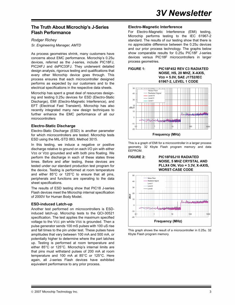
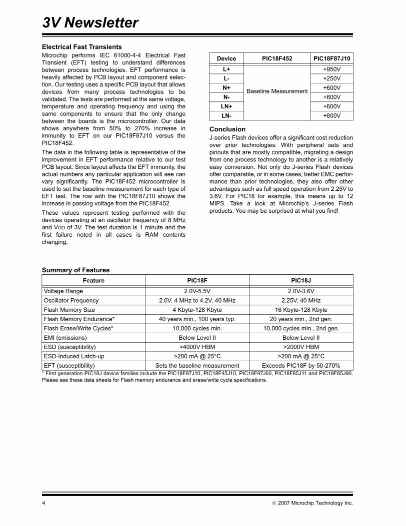
Electro-Magnetic InterferenceFor Electro-Magnetic Interference (EMI) testing,Microchip performs testing to the IEC 61967-2standard. The results of our testing show that there isno appreciable difference between the 0.25u devicesand our prior process technology. The graphs belowshow comparable results for 0.25u PIC18F J-seriesdevices versus PIC18F microcontrollers in largerprocess geometries.
FIGURE 1: PIC18F452 REV C3 RADIATED NOISE, HS, 20 MHZ, X-AXIS, VDD = 5.0V, SAE J1752/IEC 61967-2, LEVEL 1 CODE
This is a graph of EMI for a microcontroller in a larger processgeometry. 32 Kbyte Flash program memory and dataEEPROM.
FIGURE 2: PIC18F65J10 RADIATED NOISE, 5 MHZ CRYSTAL AND PLLX4 ON, VDD = 3.3V, X-AXIS, WORST-CASE CODE
This graph shows the result of a microcontroller in 0.25u. 32Kbyte Flash program memory.
dBuV
50
40
30
20
10
0
-10
-20
0.1 1 10 100 1000
Noise Floor
Radiated Signal
Level III
Level II
Level I
Frequency (MHz)
-20
-10
0
10
20
30
40
50
0.1 1 10 100 1000
dBuV
Noise Floor
Radiated Signal
Level 1
Level 2
Level3
Frequency (MHz)
© 2007 Microchip Technology Inc. 3
3V Newsletter
Electrical Fast TransientsMicrochip performs IEC 61000-4-4 Electrical FastTransient (EFT) testing to understand differencesbetween process technologies. EFT performance isheavily affected by PCB layout and component selec-tion. Our testing uses a specific PCB layout that allowsdevices from many process technologies to bevalidated. The tests are performed at the same voltage,temperature and operating frequency and using thesame components to ensure that the only changebetween the boards is the microcontroller. Our datashows anywhere from 50% to 270% increase inimmunity to EFT on our PIC18F87J10 versus thePIC18F452.The data in the following table is representative of theimprovement in EFT performance relative to our testPCB layout. Since layout affects the EFT immunity, theactual numbers any particular application will see canvary significantly. The PIC18F452 microcontroller isused to set the baseline measurement for each type ofEFT test. The row with the PIC18F87J10 shows theincrease in passing voltage from the PIC18F452.These values represent testing performed with thedevices operating at an oscillator frequency of 8 MHzand VDD of 3V. The test duration is 1 minute and thefirst failure noted in all cases is RAM contentschanging.ConclusionJ-series Flash devices offer a significant cost reductionover prior technologies. With peripheral sets andpinouts that are mostly compatible, migrating a designfrom one process technology to another is a relativelyeasy conversion. Not only do J-series Flash devicesoffer comparable, or in some cases, better EMC perfor-mance than prior technologies, they also offer otheradvantages such as full speed operation from 2.25V to3.6V. For PIC18 for example, this means up to 12MIPS. Take a look at Microchip’s J-series Flashproducts. You may be surprised at what you find!
Summary of Features
* First generation PIC18J device families include the PIC18F87J10, PIC18F45J10, PIC18F97J60, PIC18F85J11 and PIC18F85J90.Please see these data sheets for Flash memory endurance and erase/write cycle specifications.
Device PIC18F452 PIC18F87J10
L+
Baseline Measurement
+950VL- +250VN+ +600VN- +600V
LN+ +600VLN- +800V
Feature PIC18F PIC18J
Voltage Range 2.0V-5.5V 2.0V-3.6VOscillator Frequency 2.0V, 4 MHz to 4.2V, 40 MHz 2.25V, 40 MHzFlash Memory Size 4 Kbyte-128 Kbyte 16 Kbyte-128 KbyteFlash Memory Endurance* 40 years min., 100 years typ. 20 years min., 2nd gen.Flash Erase/Write Cycles* 10,000 cycles min. 10,000 cycles min., 2nd gen.EMI (emissions) Below Level II Below Level IIESD (susceptibility) >4000V HBM >2000V HBMESD-Induced Latch-up >200 mA @ 25°C >200 mA @ 25°CEFT (susceptibility) Sets the baseline measurement Exceeds PIC18F by 50-270%
4 © 2007 Microchip Technology Inc.
3V Newsletter
Motor Control in a Distributed Intelligence SystemStephen CaldwellDirector, Home Appliance Solutions GroupMany embedded control designers are starting to usemultiple microcontrollers in applications that have his-torically used a single, centralized microcontroller.These designers use auxiliary boards to control individ-ual sensors, motors, and user interfaces.This concept, often called distributed intelligence, pro-vides several potential advantages over a centralizedsystem. Distributed intelligence systems often needless SW development hours since it is easier to writeseveral simple programs compared to one large com-plex program. Also, system costs are often lower dueto reduced wiring and related components. Please readthe following article to delve further into the concept.http://epu.ref.nstu.ru/files/downloads/softndocs/Micro-chip/DSK4-2002/1010/edit/proceed/archive/9_207/index.htm.Microchip has recently introduced thedsPIC33F12MC202 family. The product is highlyoptimized for motor control solutions that requiresophisticated algorithms. It has just enough resourcesto run a motor without too many features. This enablessystem designers to obtain advance motor controlcapability at a competitive price.The product has several motor control peripherals: 8center lined PWM channels, high-speed 12-bit ADCwith 4 simultaneous samples, 2-phase quadratureencoder, 12K Flash memory and Fault interrupt pins.Typically, the dsPIC33F12MC202 is used in a distrib-uted system where another microcontroller acts as themain micro. If the main microcontroller operates at 5V,then the system designer must consider the voltagelevels translations between the products. The 3VMigration Tips and Tricks show various options for con-necting 5V and 3V products. www.micrcochip.com/3VThe dsPIC33F12MC202 is manufactured in anadvanced 3V process technology that enables 40 MIPsof processing power. This product operates from 2V-3.6V and has 5V tolerant inputs. The processing poweris critical to run sophisticated algorithms.Microchip has more than 30 application notes thatengineers use as a starting point for motor controldevelopment. These application notes include theory,algorithms, code, schematics, and tips and tricks.One application note, AN1078, covers the SensorlessField Oriented Control for a PMSM motor. The FOCalgorithm enables the designer to achieve highdynamic performance to optimize system efficiency.
For more information on Motor Control and Algorithms,visit, www.microchip.com/motor.Designing systems with multiple microcontrollers willbe the norm in the future. Savvy engineers will be ableto use products with multiple rails and still meettechnical and business goals.
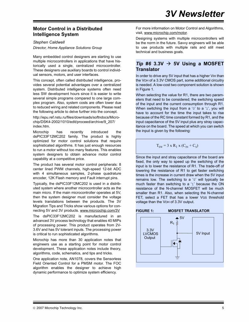
Tip #6 3.3V 5V Using a MOSFETTranslatorIn order to drive any 5V input that has a higher VIH thanthe VOH of a 3.3V CMOS part, some additional circuitryis needed. A low-cost two component solution is shownin Figure 1.When selecting the value for R1, there are two param-eters that need to be considered; the switching speedof the input and the current consumption through R1.When switching the input from a ‘0’ to a ‘1’, you willhave to account for the time the input takes to risebecause of the RC time constant formed by R1, and theinput capacitance of the 5V input plus any stray capac-itance on the board. The speed at which you can switchthe input is given by the following:
Since the input and stray capacitance of the board arefixed, the only way to speed up the switching of theinput is to lower the resistance of R1. The trade-off oflowering the resistance of R1 to get faster switchingtimes is the increase in current draw when the 5V inputremains low. The switching to a ‘0’ will typically bemuch faster than switching to a ‘1’ because the ONresistance of the N-channel MOSFET will be muchsmaller than R1. Also, when selecting the N-channelFET, select a FET that has a lower VGS thresholdvoltage than the VOH of 3.3V output.
FIGURE 1: MOSFET TRANSLATOR
TSW = 3 x R1 x (CIN + CS)
5VR1
5V Input3.3V
OutputLVCMOS
© 2007 Microchip Technology Inc. 5
3V Newsletter
dsPIC33F Motor Control Demo BoardsYann LeFaouMarketing Manager, Home Appliance Solutions GroupMicrochip offers a number of development boards andevaluation kits to make it easy to add motor controlfunctionality to your embedded design. All of the hard-ware and software are included to control thesupported motor types.Explorer 16 Development Board is a low-cost, efficientdevelopment board to evaluate the features and perfor-mance of Microchip’s new PIC24 microcontroller anddsPIC33 Digital Signal Controller (DSC) families.The dsPICDEM™ MC1L 3-Phase Low Voltage Powermodule is optimized for 3-phase motor applications thatrequire a DC bus voltage less than 50 volts and candeliver up to 400W power output. The 3-phase lowvoltage power module is intended to power BLDC andPMAC motors.
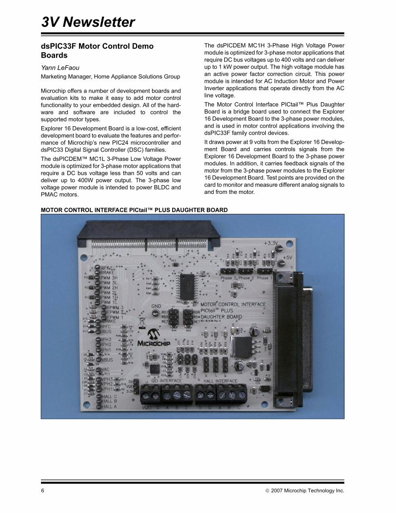
The dsPICDEM MC1H 3-Phase High Voltage Powermodule is optimized for 3-phase motor applications thatrequire DC bus voltages up to 400 volts and can deliverup to 1 kW power output. The high voltage module hasan active power factor correction circuit. This powermodule is intended for AC Induction Motor and PowerInverter applications that operate directly from the ACline voltage.The Motor Control Interface PICtail™ Plus DaughterBoard is a bridge board used to connect the Explorer16 Development Board to the 3-phase power modules,and is used in motor control applications involving thedsPIC33F family control devices.It draws power at 9 volts from the Explorer 16 Develop-ment Board and carries controls signals from theExplorer 16 Development Board to the 3-phase powermodules. In addition, it carries feedback signals of themotor from the 3-phase power modules to the Explorer16 Development Board. Test points are provided on thecard to monitor and measure different analog signals toand from the motor.
MOTOR CONTROL INTERFACE PICtail™ PLUS DAUGHTER BOARD
6 © 2007 Microchip Technology Inc.
3V Newsletter
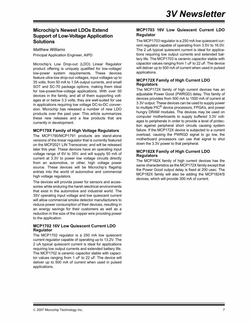
Microchip’s Newest LDOs Extend Support of Low-Voltage Application SolutionsMatthew WilliamsPrincipal Application Engineer, AIPDMicrochip’s Low Drop-out (LDO) Linear Regulatorproduct offering is uniquely qualified for low-voltage/low-power system requirements. These devicesfeature ultra-low drop-out voltages, input voltages up to35 volts, from 50 mA to 1.5A output currents, and smallSOT and SC-70 package options, making them idealfor low-power/low-voltage applications. With over 50devices in the family, and all of them supporting volt-ages at or below 3.3 volts, they are well-suited for usein applications requiring low voltage DC-to-DC conver-sion. Microchip has released a number of new LDOproducts over the past year. This article summarizesthese new releases and a few products that arecurrently in development.
MCP179X Family of High Voltage RegulatorsThe MCP1790/MCP1791 products are stand-aloneversions of the linear regulator that is currently featuredon the MCP2021 LIN Transceiver, and will be releasedlater this year. These devices have an operating inputvoltage range of 6V to 35V, and will supply 50 mA ofcurrent at 3.3V to power low voltage circuits directlyfrom an automotive, or other, high voltage powersource. These devices will be Microchip’s flagshipentries into the world of automotive and commercialhigh voltage regulators. The devices will provide power for sensors and acces-sories while enduring the harsh electrical environmentsthat exist in the automotive and industrial world. The35V operating input voltage and low quiescent currentwill allow commercial smoke detector manufacturers toreduce power consumption of their devices, resulting inan energy savings for their customers as well as areduction in the size of the copper wire providing powerto the application.
MCP1702 16V Low Quiescent Current LDO RegulatorThe MCP1702 regulator is a 250 mA low quiescentcurrent regulator capable of operating up to 13.2V. The2 uA typical quiescent current is ideal for applicationsrequiring low output currents and extended battery life.The MCP1702 is ceramic capacitor stable with capaci-tor values ranging from 1 uF to 22 uF. The device willdeliver up to 500 mA of current when used in pulsedapplications.
MCP1703 16V Low Quiescent Current LDORegulatorThe MCP1703 regulator is a 250 mA low quiescent cur-rent regulator capable of operating from 3.5V to 16.0V.The 2 uA typical quiescent current is ideal for applica-tions requiring low output currents and extended bat-tery life. The MCP1703 is ceramic capacitor stable withcapacitor values ranging from 1 uF to 22 uF. The devicewill deliver up to 500 mA of current when used in pulsedapplications.
MCP172X Family of High Current LDO RegulatorsThe MCP172X family of high current devices has anadjustable Power Good (PWRGD) delay. This family ofdevices provides from 500 mA to 1500 mA of current at3.3V output. These devices can be used to supply powerto multiple PIC® device processors, FPGA’s, and powerhungry DRAM modules. The devices may be used oncomputer motherboards to supply buffered 3.3V volt-ages to peripherals in order to provide a level of protec-tion against peripheral short circuits causing systemfailure. If the MCP172X device is subjected to a currentoverload, causing the PWRGD signal to go low, themotherboard processors can use that signal to shutdown the 3.3V power to that peripheral.
MCP182X Family of High Current LDO RegulatorsThe MCP182X family of high current devices has thesame characteristics as the MCP172X family except thatthe Power Good output delay is fixed at 200 usec. TheMCP182X family will also be adding the MCP1824/Sdevices, which will provide 300 mA of current.
© 2007 Microchip Technology Inc. 7
3V Newsletter
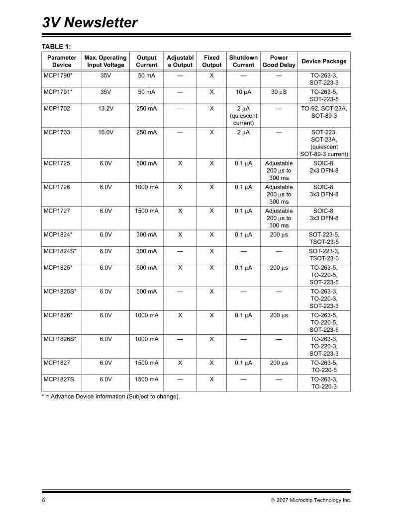
TABLE 1:* = Advance Device Information (Subject to change).
Parameter Device
Max. Operating Input Voltage
Output Current
Adjustable Output
Fixed Output
Shutdown Current
Power Good Delay Device Package
MCP1790* 35V 50 mA — X — — TO-263-3, SOT-223-3
MCP1791* 35V 50 mA — X 10 μA 30 μS TO-263-5, SOT-223-5
MCP1702 13.2V 250 mA — X 2 μA (quiescent
current)
— TO-92, SOT-23A, SOT-89-3
MCP1703 16.0V 250 mA — X 2 μA — SOT-223, SOT-23A, (quiescent
SOT-89-3 current)MCP1725 6.0V 500 mA X X 0.1 μA Adjustable
200 μs to 300 ms
SOIC-8, 2x3 DFN-8
MCP1726 6.0V 1000 mA X X 0.1 μA Adjustable 200 μs to 300 ms
SOIC-8, 3x3 DFN-8
MCP1727 6.0V 1500 mA X X 0.1 μA Adjustable 200 μs to 300 ms
SOIC-8, 3x3 DFN-8
MCP1824* 6.0V 300 mA X X 0.1 μA 200 μs SOT-223-5, TSOT-23-5
MCP1824S* 6.0V 300 mA — X — — SOT-223-3, TSOT-23-3
MCP1825* 6.0V 500 mA X X 0.1 μA 200 μs TO-263-5, TO-220-5, SOT-223-5
MCP1825S* 6.0V 500 mA — X — — TO-263-3, TO-220-3, SOT-223-3
MCP1826* 6.0V 1000 mA X X 0.1 μA 200 μs TO-263-5, TO-220-5, SOT-223-5
MCP1826S* 6.0V 1000 mA — X — — TO-263-3, TO-220-3, SOT-223-3
MCP1827 6.0V 1500 mA X X 0.1 μA 200 μs TO-263-5, TO-220-5
MCP1827S 6.0V 1500 mA — X — — TO-263-3, TO-220-3
8 © 2007 Microchip Technology Inc.

Recent IssuesThe current issue of this newsletter is available from the Microchip web site at http://www.microchip.com/3Volts.
ISSUE 3, DECEMBER 2006• Introduction• “Robustness of 3V Systems”• “Using MPLAB® REAL ICE™ Probe In Low-Voltage Applications”• “PICDEM™ HPC Explorer Board”• “dsPICDEM™ 1.1 Plus”• “Tip #1 Standby Current Reduction Technique for J Devices”• “Bridging the Rails”• Tip #2 Driving Bipolar Transistors
ISSUE 2, MARCH 2006• Introduction• “Different Ways to Develop 3V From 5V for Multi-Voltage Applications”• “Fundamentals on Digital Interface Using Two Rails”• “TIP #1 Lower Cost Alternative Power System Using 3 Rectifier Diodes”• “3V VDD FAQ Items”• “Utilizing CAN and LIN in 3 Volt Embedded Designs”• “TIP #2 Driving N-Channel MOSFET Transistors”
ISSUE 1, DECEMBER 2005• “Why 3V”• “Programming at 3V VDD”• “Serial EEPROMs for 3V Applications”• “Driving Microcontrollers to 3V”• “Microchip Provides an Impressive Portfolio of Low-Voltage Analog and Interface Design Solutions”
Information contained in this publication regarding deviceapplications and the like is provided only for your convenienceand may be superseded by updates. It is your responsibility toensure that your application meets with your specifications.MICROCHIP MAKES NO REPRESENTATIONS OR WAR-RANTIES OF ANY KIND WHETHER EXPRESS OR IMPLIED,WRITTEN OR ORAL, STATUTORY OR OTHERWISE,RELATED TO THE INFORMATION, INCLUDING BUT NOTLIMITED TO ITS CONDITION, QUALITY, PERFORMANCE,MERCHANTABILITY OR FITNESS FOR PURPOSE.Microchip disclaims all liability arising from this information andits use. Use of Microchip devices in life support and/or safetyapplications is entirely at the buyer’s risk, and the buyer agreesto defend, indemnify and hold harmless Microchip from any andall damages, claims, suits, or expenses resulting from suchuse. No licenses are conveyed, implicitly or otherwise, underany Microchip intellectual property rights.
© 2007 Microchip Technology Inc.
Trademarks
The Microchip name and logo, the Microchip logo, Accuron, dsPIC, KEELOQ, KEELOQ logo, microID, MPLAB, PIC, PICmicro, PICSTART, PRO MATE, rfPIC, and SmartShunt are registered trademarks of Microchip Technology Incorporated in the U.S.A. and other countries.
AmpLab, FilterLab, Linear Active Thermistor, Migratable Memory, MXDEV, MXLAB, SEEVAL, SmartSensor and The Embedded Control Solutions Company are registered trademarks of Microchip Technology Incorporated in the U.S.A.
Analog-for-the-Digital Age, Application Maestro, CodeGuard, dsPICDEM, dsPICDEM.net, dsPICworks, ECAN, ECONOMONITOR, FanSense, FlexROM, fuzzyLAB, In-Circuit Serial Programming, ICSP, ICEPIC, Mindi, MiWi, MPASM, MPLAB Certified logo, MPLIB, MPLINK, PICkit, PICDEM, PICDEM.net, PICLAB, PICtail, PowerCal, PowerInfo, PowerMate, PowerTool, REAL ICE, rfLAB, Select Mode, Smart Serial, SmartTel, Total Endurance, UNI/O, WiperLock and ZENA are trademarks of Microchip Technology Incorporated in the U.S.A. and other countries.
SQTP is a service mark of Microchip Technology Incorporated in the U.S.A.
All other trademarks mentioned herein are property of their respective companies.
© 2007, Microchip Technology Incorporated, Printed in the U.S.A., All Rights Reserved.
Printed on recycled paper.
9
10 © 2007 Microchip Technology Inc.
AMERICASCorporate Office2355 West Chandler Blvd.Chandler, AZ 85224-6199Tel: 480-792-7200 Fax: 480-792-7277Technical Support: http://support.microchip.comWeb Address: www.microchip.comAtlantaDuluth, GA Tel: 678-957-9614 Fax: 678-957-1455BostonWestborough, MA Tel: 774-760-0087 Fax: 774-760-0088ChicagoItasca, IL Tel: 630-285-0071 Fax: 630-285-0075DallasAddison, TX Tel: 972-818-7423 Fax: 972-818-2924DetroitFarmington Hills, MI Tel: 248-538-2250Fax: 248-538-2260KokomoKokomo, IN Tel: 765-864-8360Fax: 765-864-8387Los AngelesMission Viejo, CA Tel: 949-462-9523 Fax: 949-462-9608Santa ClaraSanta Clara, CA Tel: 408-961-6444Fax: 408-961-6445TorontoMississauga, Ontario, CanadaTel: 905-673-0699 Fax: 905-673-6509
ASIA/PACIFICAsia Pacific OfficeSuites 3707-14, 37th FloorTower 6, The GatewayHarbour City, KowloonHong KongTel: 852-2401-1200Fax: 852-2401-3431Australia - SydneyTel: 61-2-9868-6733Fax: 61-2-9868-6755China - BeijingTel: 86-10-8528-2100 Fax: 86-10-8528-2104China - ChengduTel: 86-28-8665-5511Fax: 86-28-8665-7889China - FuzhouTel: 86-591-8750-3506 Fax: 86-591-8750-3521China - Hong Kong SARTel: 852-2401-1200 Fax: 852-2401-3431China - QingdaoTel: 86-532-8502-7355Fax: 86-532-8502-7205China - ShanghaiTel: 86-21-5407-5533 Fax: 86-21-5407-5066China - ShenyangTel: 86-24-2334-2829Fax: 86-24-2334-2393China - ShenzhenTel: 86-755-8203-2660 Fax: 86-755-8203-1760China - ShundeTel: 86-757-2839-5507 Fax: 86-757-2839-5571China - WuhanTel: 86-27-5980-5300Fax: 86-27-5980-5118China - XianTel: 86-29-8833-7250Fax: 86-29-8833-7256
ASIA/PACIFICIndia - BangaloreTel: 91-80-4182-8400 Fax: 91-80-4182-8422India - New DelhiTel: 91-11-4160-8631Fax: 91-11-4160-8632India - PuneTel: 91-20-2566-1512Fax: 91-20-2566-1513Japan - YokohamaTel: 81-45-471- 6166 Fax: 81-45-471-6122Korea - GumiTel: 82-54-473-4301Fax: 82-54-473-4302Korea - SeoulTel: 82-2-554-7200Fax: 82-2-558-5932 or 82-2-558-5934Malaysia - PenangTel: 60-4-646-8870Fax: 60-4-646-5086Philippines - ManilaTel: 63-2-634-9065Fax: 63-2-634-9069SingaporeTel: 65-6334-8870Fax: 65-6334-8850Taiwan - Hsin ChuTel: 886-3-572-9526Fax: 886-3-572-6459Taiwan - KaohsiungTel: 886-7-536-4818Fax: 886-7-536-4803Taiwan - TaipeiTel: 886-2-2500-6610 Fax: 886-2-2508-0102Thailand - BangkokTel: 66-2-694-1351Fax: 66-2-694-1350
EUROPEAustria - WelsTel: 43-7242-2244-39Fax: 43-7242-2244-393Denmark - CopenhagenTel: 45-4450-2828 Fax: 45-4485-2829France - ParisTel: 33-1-69-53-63-20 Fax: 33-1-69-30-90-79Germany - MunichTel: 49-89-627-144-0 Fax: 49-89-627-144-44Italy - Milan Tel: 39-0331-742611 Fax: 39-0331-466781Netherlands - DrunenTel: 31-416-690399 Fax: 31-416-690340Spain - MadridTel: 34-91-708-08-90Fax: 34-91-708-08-91UK - WokinghamTel: 44-118-921-5869Fax: 44-118-921-5820
WORLDWIDE SALES AND SERVICE
12/08/06