issue 3 - zip-clip
TRANSCRIPT

ISSUE 3

2 3
Contents
About Zip-Clip 4
Technical Information 5
How it Works 6
Product Selector 7
Rize 8-9
Zip-Lock 10-11
Loop-It 12-13
Con-Lock 14-15
Anchor-It 16-17
Thread-It 18-19
Dec-Lock 20-21
Knock-It 22-23
Toggle-It 24-25
Snap-It 26-27
Uni-Lock 28-29
Shot-Lock 30-31
Plus On-Wire 32-33
Chan-Lock 34-35
Try-Lock 36-37
Luma-Lock 38-39
Y-It 40-41
Span-Lock 42-43
Zip-Grip 44-45
H-Frame 46-47
Accessories 48-49
PREFABRICATIONS 50-51
SPECIFICATIONS 52-53
ENVIRONMENTAL POLICY 54
Copyright of Zip-Clip Ltd 2017
All descriptions and illustrations in this manual are intended for guidance purposes only. Zip-Clip Ltd reserves the right to change the information, products and specifications in this manual for a variety of reasons, without prior notice. The information in this manual is provided “as is” at the date specified on the back cover. Updates will not be issued automatically
Wrap - around
Concrete
Decking
Purlins
Service Supports
Timber
Catenary
Roof Support
Zip-Clip - A Global Brand

4 5
About ZIPCLIP
Safety | Suspension | Speed
Who is Zip-Clip? We are manufacturers and designers of high-spec suspension systems for all your HVAC, Electrical, Mechanical & Signage requirements.
What Is It? It is a range of innovative products designed for speed and ease of use. The clip is manufactured from a high quality zinc alloy. The oil impregnated sintered metal wedge is designed to offer the best locking solution. The stainless steel spring ensures the wedge engages first time. The galvanised high tensile wire rope supplied offers you a better SWL than those found on the market. All our engineered suspension products are designed with quality and safety in mind.
Tested? All our products are independently tested off site by NEL/TUV, MELBTEST, NATA, SATRA, Lloyds British and Apave and all clips are UL certificated. For copies of our test certificates please contact our offices or download them from our website - www.zip-clip.com
The Professional Choice Zip-Clip has created a “Professional Choice” range of suspension systems all of high specification. You can easily spot this range of products throughout the Zip-Clip catalogue thanks to the Professional Choice symbol.
What are the advantages of using a Zip-Clip wire system? Using a wire rope suspension system provides many advantages:• Key free release system• Easier to transport• 100 metre coil is equivalent to 30 x 3 metre lengths of threaded rod• Easier to handle• Cold cut, no hot work permit required• Vibration reduction: threaded rod has a vibration absorption of 50%, whereas wire rope hangers absorb vibration in
excess of 75%.• Reduced labour cost• Reduced risk of injury• Aesthetical• Reduces individual components (ie nuts, washers, square plates, rod...)• Reduces impact on the environment
Where can I use a wire system? HVAC AND MECHANICAL• Spiral Ducting• Rectangular Ducting• Radiant Heat Panels• Fan Coil Units• Chilled Beams• Gas pipes• Water Pipes
SPECIALIST• Seismic areas• Christmas decorations• Accoustic supports• Pest control• Museum installations• Exhibition installations• Retail displays• Stainless Solutions
ELECTRICAL• Luminaires• Busbar• Cable Basket• Cable Ladder• Trunking• High Bays• CCTV Cameras• Secondary Support• Sound Systems
*For specialist applications, please contact our technical department on 0044 1686 623366
Manufacturers Recommendations?Zip-Clip’s unique system is designed to support static loads only. Dynamic and shock loadings can greatly increase the overall weight of the product being suspended and therefore can compromise the Safe Working Load of the suspension.
• To ensure integrity and safety of the systems only Zip-Clip cable should be used• Do not exceed the Safe Working Load of the product• Do not use coated cable• Do not paint or apply any other coating• Do not apply lubricant• Do not use for lifting• Remove any damaged cable end prior to inserting into the clip
All stated Safe Working Loads and certifications are based on the product being used in conjunction with our high tensile Zip-Clip wire. Zip-Clip are not able to guarantee the Safe Working Load of a product used with a non Zip-Clip wire and cannot support projects where non Zip-Clip wire has been used.
Why
Safety | Suspension | Speed

6 7
How it Works
Safety | Suspension | Speed
Product Selector
Wr
ap
Ar
ou
nd
Ap
pl
ica
tio
ns
Co
nc
re
te
Ap
pl
ica
tio
ns
De
ck
ing
Ap
pl
ica
tio
ns
Pu
rl
ins
Tim
be
r a
nd
Ot
he
r S
ub
st
ra
te
s
Se
rv
ice
Su
pp
or
ts
Ro
of
Su
pp
or
t S
ys
te
ms
Ca
te
na
ry
Sy
st
em
s
8-9 Rize
10-11 Zip-Lock
12-13 Loop-It
14-15 Con-Lock
16-17 Anchor-It
18-19 Thread-It
20-21 Dec-Lock
22-23 Knock-It
24-25 Toggle-It
26-27 Snap-It
28-29 Uni-Lock
30-31 Shot-Lock
32-33 Plus On-Wire
34-35 Chan-Lock
36-37 Try-Lock
38-39 Luma-Lock
40-41 Y-It
42-43 Span-Lock
44-45 Zip-Grip
46-47 H-Frame
50-51 Prefabrications
• Pass the wire through the zip-clip• Loop the wire through or around the anchor point• Pass the wire back through the zip-clip allowing 15cm of wire protruding• Apply tension• Always confirm engagement of the zip-clip on the wire by pushing the pin in the opposite direction of the arrows
indicated on the zip-clip• To adjust, take the load off and pull the tail slightly to disengage the teeth, then release using the adjustment pin - no
tools required
The KL200 can be used to make a figure of eight suspension, using one clip: • Pass the wire into the “through hole” in the KL200 and then around your fixing or anchor point. Pass the wire end
through the locking channel in the KL200 and pull through 15cm of free wire• Pass the other end of the wire through your bracket or around your suspension and back through the locking channel
allowing 15cm of free wire through the clip• Always confirm engagement of the zip-clip on the wire by pushing the pin in the opposite direction of the arrows
indicated on the zip-clip• Prior to load being applied, the wire can be adjusted in either direction.
With the load off the wire, push the release pin in the direction of the arrow on the zip-clip. This will release the locking wedge and allow the wire rope to be moved freely on either direction. After a load has been applied, it may be necessary to pull the cable slightly to disengage the teeth on the wedge. Be sure the load is fully supported before attempting adjustment.
The KL50, KL100 & KL150 The KL200
Wrap - around
Concrete
Decking
Purlins
Service Supports
Timber
Catenary
Roof Support

8 9
Rize
Safety | Suspension | Speed
The Specifics The range consists of a range of wire reels and zip-clips with a choice of Safe Working Loads:• G 10kg SWL• S 50kg SWL• Y 120kg SWL• P 230kg SWL• N 500kg SWL
The Applications
• Wrap around applications• Suitable for use with a wide range of fixing brackets
including: UNI1, UNI2, UNI3, CLA1, MA6810, T920514
• Cold Room Ceilings• Trapeze Brackets
The Technical Information
• Key free release system• No pre-site visits required• Ideal for long drop lengths• Any spare material can be used on following projects• Only wire cutter required• Can be used as a wrap around application and with a
wide range of brackets.• Wire supplied in dispensing box - avoiding risk of
wire bird nesting
Zip-clips are also available in a lockable version offering a tamper proof installation.
The Installation:• Unscrew the M4 locking nut and bolt until the adjustment pin is
pushed back fully.• Pass one end of the wire through the zip-clip in the direction of
the arrow and draw enough wire to around your fixing point.• Pass the wire back through the zip-clip leaving at least 15cm of
wire protruding.• Tighten the M4 locking nut and bolt until the adjustment can no
longer be moved
The Installation
• Cut wire to desired length for the drop required• Pass one end of the wire through the zip-clip in the
direction of the arrow and draw through enough wire to go around your fixing point
• Pass the wire end back through the zip-clip leaving at least 15cm of free wire protruding
• At the other end again pass the wire through the zip-clip in the direction of the arrow
• Pass the free end of wire around your suspension or through your fixing and back through the zip-clip leaving 15cm of wire protruding.
• Always confirm engagement of the zip-clip on the wire by pushing the pin in the opposite direction to the arrows indicated
Standard Clip
Lockable clip
The Range The range consists of wire reels and zip-clips with a choice of Safe Working Loads (SWL).
Rize
Product Code
Description SWLPack Qty.
KL50 Rize KL50 10kg SWL 10kg 10
R200G 200 Mtr G wire reel in dispenser box 10kg 1
R100G/SS 100 Mtr Stainless Steel AISI 316 G Wire Reel 8kg 1
R200G/SS 200 Mtr Stainless Steel AISI 316 G Wire Reel 8kg 1
KL100 Rize KL100 50kg SWL 50kg 10
R100S 100 Mtr S wire reel in dispenser box 50kg 1
R200S 200 Mtr S wire reel in dispenser box 50kg 1
R500S 500 Mtr S Wire Reel 50kg 1
R100S/SS 100 Mtr Stainless Steel AISI 316 S Wire Reel 45kg 1
KL150 Rize KL150 120kg SWL 120kg 10
R100Y 100 Mtr Y Wire Reel 120kg 1
R100Y/SS 100 Mtr Stainless Steel AISI 316 Y Wire Reel 100kg 1
KL200 Rize KL200 230kg SWL 230kg 10
R100P 100 Mtr P Wire Reel 230kg 1
R100P/SS 100 Mtr Stainless Steel AISI 316 P Wire Reel 200kg 1
KL600 Rize KL600 500kg SWL 500kg 10
R100N 100 mtr N wire reel 500kg 1
KL100LOK Rize KL100 50kg SWL Lockable 50kg 10
KL150LOK Rize KL150 120kg SWL Lockable 120kg 10
KL200LOK Rize KL200 230kg SWL Lockable 230kg 10
KL600LOK Rize KL600 500kg SWL Lockable 500kg 10
KL100LOK KL150LOK KL200LOK KL600LOK
KL100 KL150 KL200 KL600KL50

10 11
Zip-Lock
Safety | Suspension | Speed
The Specifics The range consists of a pre-determined length of wire from 1 metre to 10 metres with a choice of Safe Working Load:• G 10kg• S 50kg• Y 120kg The system consists of wire and zip-clip with a friction free eye termination.
The Applications
Suitable for wrap around installations including:• Beams• Purlins• Roof Trusses• And all other existing features
The Technical Information
• Key free release system• Precision Swaged Eye• Frictionless system – No wire on wire• Simple to use• DW144 approved• Trivalent zinc and clear galvanised• Suspension can be inverted• High tensile galvanised wire 1960N/mm² grade 7 x 7
construction• BSEN 12385 Standard
The Installation
• Pass the wire around your purlin or beam• Pass the free end of the wire through the eye to
create a friction free fixing• Pass the wire through the zip-clip in the direction of
the arrow• Pass through or around your required suspension
and back through the zip-clip leaving 15cm of wire protruding
• Always confirm engagement of the zip-clip on the wire by pushing the pin in the opposite direction to the arrow’s indicated
The Range The system consists of wire and zip-clip with a friction free eye termination.
Zip-Lock
Product Code
Description SWLPack Qty.
ZLG1 1 Mtr eye suspension system 10kg 10
ZLG1.5 1.5 Mtr eye suspension system 10kg 10
ZLG2 2 Mtr eye suspension system 10kg 10
ZLG3 3 Mtr eye suspension system 10kg 10
ZLG4 4 Mtr eye suspension system 10kg 10
ZLG5 5 Mtr eye suspension system 10kg 10
ZLG6 6 Mtr eye suspension system 10kg 10
ZLG7 7 Mtr eye suspension system 10kg 10
ZLG8 8 Mtr eye suspension system 10kg 10
ZLG9 9 Mtr eye suspension system 10kg 10
ZLG10 10 Mtr eye suspension system 10kg 10
ZLS1 1 Mtr eye suspension system 50kg 10
ZLS1.5 1.5 Mtr eye suspension system 50kg 10
ZLS2 2 Mtr eye suspension system 50kg 10
ZLS3 3 Mtr eye suspension system 50kg 10
ZLS4 4 Mtr eye suspension system 50kg 10
ZLS5 5 Mtr eye suspension system 50kg 10
ZLS6 6 Mtr eye suspension system 50kg 10
ZLS7 7 Mtr eye suspension system 50kg 10
ZLS8 8 Mtr eye suspension system 50kg 10
ZLS9 9 Mtr eye suspension system 50kg 10
ZLS10 10 Mtr eye suspension system 50kg 10
ZLY1 1 Mtr eye suspension system 120kg 10
ZLY1.5 1.5 Mtr eye suspension system 120kg 10
ZLY2 2 Mtr eye suspension system 120kg 10
ZLY3 3 Mtr eye suspension system 120kg 10
ZLY4 4 Mtr eye suspension system 120kg 10
ZLY5 5 Mtr eye suspension system 120kg 5
ZLY6 6 Mtr eye suspension system 120kg 5
ZLY7 7 Mtr eye suspension system 120kg 5
ZLY8 8 Mtr eye suspension system 120kg 5
ZLY9 9 Mtr eye suspension system 120kg 5
ZLY10 10 Mtr eye suspension system 120kg 5
ZLG
ZLS & ZLY

12 13
Loop-It
Safety | Suspension | Speed The Range The system consists of wire and zip-clip with a ferruled loop termination.
Loop-It
Product Code
Description SWLPack Qty.
PLEK1G 1 Mtr standard loop suspension system 10kg 10
PLEK2G 2 Mtr standard loop suspension system 10kg 10
PLEK3G 3 Mtr standard loop suspension system 10kg 10
PLEK4G 4 Mtr standard loop suspension system 10kg 10
PLEK5G 5 Mtr standard loop suspension system 10kg 10
PLEK10G 10 Mtr standard loopsuspension system 10kg 10
PLEK1S 1 Mtr standard loop suspension system 45kg 10
PLEK2S 2 Mtr standard loop suspension system 45kg 10
PLEK3S 3 Mtr standard loop suspension system 45kg 10
PLEK4S 4 Mtr standard loop suspension system 45kg 10
PLEK5S 5 Mtr standard loop suspension system 45kg 10
PLEK10S 10 Mtr standard loop suspension system 45kg 10
PLEK1Y 1 Mtr standard loop suspension system 90kg 10
PLEK2Y 2 Mtr standard loop suspension system 90kg 10
PLEK3Y 3 Mtr standard loop suspension system 90kg 10
PLEK4Y 4 Mtr standard loop suspension system 90kg 10
PLEK5Y 5 Mtr standard loop suspension system 90kg 5
PLEK10Y 10 Mtr standard loop suspension system 90kg 5
PLEK1P 1 Mtr standard loop suspension system 200kg 10
PLEK2P 2 Mtr standard loop suspension system 200kg 10
PLEK3P 3 Mtr standard loop suspension system 200kg 10
PLEK4P 4 Mtr standard loop suspension system 200kg 10
PLEK5P 5 Mtr standard loop suspension system 200kg 5
PLEK10P 10 Mtr standard loop suspension system 200kg 5
PLEK1N 1 Mtr standard loop suspension system 500kg 5
PLEK2N 2 Mtr standard loop suspension system 500kg 5
PLEK3N 3 Mtr standard loop suspension system 500kg 5
PLEK4N 4 Mtr standard loop suspension system 500kg 5
PLEK5N 5 Mtr standard loop suspension system 500kg 5
PLEK10N 10 Mtr standard loop suspension system 500kg 5
The Specifics The range consists of a pre-determined length of wire from 1 metre to 10 metres with a choice of Safe Working Load:• G 10kg SWL• S 45kg SWL• Y 90kg SWL• P 200kg SWL• N 500kg SWL
The system consists of wire and zip-clip with a ferruled loop termination.
The Applications
Suitable for wrap around applications including:• Beams• Purlins• Roof Trusses• And all other existing features
The Technical Information
• Key free release system• Simple to use• Suspension can be inverted• High tensile galvanised wire 1960N/mm² grade 7 x 7
construction• BSEN 12385 standard
The Installation
• Pass the wire around the purlin or beam• Pass the free end of the wire through the loop• Pass the wire through the zip-clip in the direction of
the arrow• Pass through or around the required suspension
and back through the zip-clip leaving 15 cm of wire protruding
• Always confirm engagement of the zip-clip on the wire by pushing the pin in the opposite direction to the arrows indicated

14 15
Con-Lock
Safety | Suspension | Speed
The Specifics The range consists of a pre-determined length of wire from 1 metre to 10 metres with a choice of Safe Working Load:• G 10kg• S 50kg• Y 90kg
The system consists of wire and zip-clip with a CLA1 concrete anchor termination.
The Applications
Suitable for concrete applications including:• Cracked concrete• Reinforced concrete• Slagged concrete• Hollow pot
The Technical Information
• Key free release system• No claw back required• Nail anchor for hammer set installation• The installed nail anchor expands automatically under load,
pulls the cone into the expansion clip and expands against the wall of the concrete.
• Can also be supplied with a double drop• Shallow embedment• ETA approved• BS8539 Compliant• High tensile galvanised wire 1960 N/mm² grade 7 x 7
construction• BSEN 12385 standard
The Installation
• Drill a 6mm hole to a minimum depth of 30mm• Blow the hole clean of dust and debris• Hammer in the fixing• Anchor is now fixed, no claw back required• Pass the wire through the zip-clip in the direction of the
arrow• Pass through or around your required suspension and back
through the zip-clip leaving 15cm of wire protruding• Always confirm engagement of the zip-clip on the wire
by pushing the pin in the opposite direction to the arrows indicated
BS8539 Compliant
The Range The system consists of wire and zip-clip with a CLA1 concrete anchor termination.
Con-Lock
Product Code
Description SWLPack Qty.
CLG1 1 Mtr concrete suspension system 10kg 10
CLG2 2 Mtr concrete suspension system 10kg 10
CLG3 3 Mtr concrete suspension system 10kg 10
CLG4 4 Mtr concrete suspension system 10kg 10
CLG5 5 Mtr concrete suspension system 10kg 10
CLG10 10 Mtr concrete suspension system 10kg 10
CLS1 1 Mtr concrete suspension system 50kg 10
CLS2 2 Mtr concrete suspension system 50kg 10
CLS3 3 Mtr concrete suspension system 50kg 10
CLS4 4 Mtr concrete suspension system 50kg 10
CLS5 5 Mtr concrete suspension system 50kg 10
CLS10 10 Mtr concrete suspension system 50kg 10
CLY1 1 Mtr concrete suspension system 90kg 10
CLY2 2 Mtr concrete suspension system 90kg 10
CLY3 3 Mtr concrete suspension system 90kg 10
CLY4 4 Mtr concrete suspension system 90kg 10
CLY5 5 Mtr concrete suspension system 90kg 5
CLY10 10 Mtr concrete suspension system 90kg 5
ETA-

16 17
Anchor-It
Safety | Suspension | Speed The Range The system consists of wire and zip-clip with a ferruled CLA2 concrete anchor termination.
Anchor-It
Product Code
Description SWLPack Qty.
PLCAK1G 1 Mtr standard concrete suspension system 10kg 10
PLCAK2G 2 Mtr standard concrete suspension system 10kg 10
PLCAK3G 3 Mtr standard concrete suspension system 10kg 10
PLCAK4G 4 Mtr standard concrete suspension system 10kg 10
PLCAK5G 5 Mtr standard concrete suspension system 10kg 10
PLCAK10G 10 Mtr standard concrete suspension system 10kg 10
PLCAK1S 1 Mtr standard concrete suspension system 35kg 10
PLCAK2S 2 Mtr standard concrete suspension system 35kg 10
PLCAK3S 3 Mtr standard concrete suspension system 35kg 10
PLCAK4S 4 Mtr standard concrete suspension system 35kg 10
PLCAK5S 5 Mtr standard concrete suspension system 35kg 10
PLCAK10S 10 Mtr standard concrete suspension system 35kg 10
The Specifics The range consists of a predetermined length of wire from 1 metre to 10 metres with a choice of Safe Working Load:• G 10kg SWL• S 35kg SWL
The system consists of wire and zip-clip with a ferruled CLA2 concrete anchor termination
The Applications
Suitable for concrete applications including:• Solid brick• Compressive resistant stone• Reinforced concrete• Slagged concrete C15/C35
The Technical Information
• Key free release system• Vibration resistant• Zinc plated pre-expanded through bolt • 30mm long• 5mm wide• 6mm head width • 30mm embedment depth• 5mm drill diameter required• High tensile galvanised wire 1960N/mm² grade 7 x 7
construction• BSEN 12385 standard
The Installation
• Drill a 5mm hole to a minimum depth of 30mm• Blow the hole clean of dust and debris• Drive the anchor into the hole until the head is firmly
seated against the base material. Be sure the anchor is driven to the required embedment depth.
• Pass the wire through the zip-clip in the direction of the arrow
• Pass through or around your required suspension and back through the zip-clip leaving 15cm of wire protruding.
• Always confirm engagement of the zip-clip on the wire by pushing the pin in the opposite direction to the arrows indicated

18 19
Thread-It
Safety | Suspension | Speed The Range The system consists of wire and zip-clip with a choice of M6 or M8 threaded termination.
Thread-It
Product Code
Description SWLPack Qty.
PLTRK1G/M6x20 1 M standard M6x20 threaded suspension system 10kg 10
PLTRK2G/M6x20 2 M standard M6x20 threaded suspension system 10kg 10
PLTRK3G/M6x20 3 M standard M6x20 threaded suspension system 10kg 10
PLTRK4G/M6x20 4 M standard M6x20 threaded suspension system 10kg 10
PLTRK5G/M6x20 5 M standard M6x20 threaded suspension system 10kg 10
PLTRK10G/M6x20 10 M standard M6x20 threaded suspension system 10kg 10
PLTRK1S/M6x45 1 M standard M6x45 threaded suspension system 45kg 10
PLTRK2S/M6x45 2 M standard M6x45 threaded suspension system 45kg 10
PLTRK3S/M6x45 3 M standard M6x45 threaded suspension system 45kg 10
PLTRK4S/M6x45 4 M standard M6x45 threaded suspension system 45kg 10
PLTRK5S/M6x45 5 M standard M6x45 threaded suspension system 45kg 10
PLTRK10S/M6x45 10 M standard M6x45 threaded suspension system 45kg 10
PLTRK1S/M8X25 1 M standard M8x25 threaded suspension system 45kg 10
PLTRK2S/M8X25 2 M standard M8x25 threaded suspension system 45kg 10
PLTRK3S/M8X25 3 M standard M8x25 threaded suspension system 45kg 10
PLTRK4S/M8X25 4 M standard M8x25 threaded suspension system 45kg 10
PLTRK5S/M8X25 5 M standard M8x25 threaded suspension system 45kg 10
PLTRK10S/M8X25 10 M standard M8x25 threaded suspension system 45kg 10
PLTRK1Y/M8X25 1 M standard M8x25 threaded suspension system 90kg 10
PLTRK2Y/M8X25 2 M standard M8x25 threaded suspension system 90kg 10
PLTRK3Y/M8X25 3 M standard M8x25 threaded suspension system 90kg 10
PLTRK4Y/M8x25 4 M standard M8x25 threaded suspension system 90kg 10
PLTRK5Y/M8x25 5 M standard M8x25 threaded suspension system 90kg 5
PLTRK10Y/M8x25 10 M standard M8x25 threaded suspension system 90kg 5
EYEBOLT SIZES ALSO AVAILABLE:
IMAGE PRODUCT CODE DESCRIPTION
UNI6M60 M6 x 60mm eyebolt
UNI8M60 M8 x 60mm eyebolt
UNI10M60 M10 x 60mm eyebolt
M8
M6The Specifics The range consists of a predetermined length of wire from 1 metre to 10 metres with a choice of Safe Working Load:• G 10kg SWL - M6 x 20 threaded end• S 45kg SWL - M6 x 45 or M8 x 25 threaded end• Y 90kg SWL - M8 x 25 threaded end
The system consists of wire and zip-clip with a choice of M6 or M8 threaded termination.
The Applications
Suitable for:• Concrete• Lindapter wedges• Busbar• Lighting trunking• Ducting• Cable management• Signage
The Technical Information
• Key free release system• Comes with M6 or M8 eyebolt as standard• Other eyebolts available on request• Suspension can be inverted• High tensile galvanised wire 1960N/mm² grade 7 x 7
construction• BSEN 12385 standard
The Installation
• For use in concrete, ensure that the drop in anchor is correctly fixed then thread the M6/M8 stud into place
• Pass the wire through the zip-clip in the direction of the arrow
• Pass through or around your required suspension and back through the zip-clip leaving 15cm of wire protruding
• The stud can be used in reverse configuration and threaded into the product to be suspended
• Always confirm engagement of the zip-clip on the wire by pushing the pin in the opposite direction to the arrows indicated

20 21
Dec-Lock
Safety | Suspension | Speed
The Specifics The range consists of a pre-determined length of wire from 1 metre to 10 metres with a choice of Safe Working Loads:• G 10kg• S 50kg
The system consists of wire and zip-clip with a decking fixing termination.
The Applications
Suitable for decking applications including:• Kingspan Structural Products• Structural Metal Decks (SMD) and other steel
decking manufacturers
The Technical Information
• Key free release system• All components are fully assembled• No onsite assembly required• Lockable system, no drilling required• Suitable where access to purlin is not available• CNC engineered M6 x 45mm eyelet• Trivalent zinc and clear galvanised eyelet, nut and
washer• High tensile galvanised wire 1960 N/mm² grade 7 x
7 construction• BSEN 12385 Standard
The Installation
• Push the end fixing into decking profile and turn through 90 degrees
• Screw the eyebolt to the top of the decking profile• Pass the wire through the zip-clip in the direction of
the arrow• Pass through or around your required suspension
and back through the zip-clip leaving 15cm of wire protruding
• Always confirm engagement of the zip-clip on the wire by pushing the pin in the opposite direction to the arrows indicated
The Range The system consists of wire and zip-clip with a decking fixing termination.
Dec-Lock
Product Code
Description SWLPack Qty.
DLG1 1 Mtr decking suspension system 10kg 10
DLG2 2 Mtr decking suspension system 10kg 10
DLG3 3 Mtr decking suspension system 10kg 10
DLG4 4 Mtr decking suspension system 10kg 10
DLG5 5 Mtr decking suspension system 10kg 10
DLG10 10 Mtr decking suspension system 10kg 10
DLS1 1 Mtr decking suspension system 50kg 10
DLS2 2 Mtr decking suspension system 50kg 10
DLS3 3 Mtr decking suspension system 50kg 10
DLS4 4 Mtr decking suspension system 50kg 10
DLS5 5 Mtr decking suspension system 50kg 10
DLS10 10 Mtr decking suspension system 50kg 10
DECKING TYPE
STANDARD WEDGE Size: 25mm (Top of Wedge) x 18mm (Base of Wedge) x 12mm (Width)
MINI WEDGESize: 19mm (Top of Wedge) x 12mm (Base of Wedge) x 9.5mm (Width)
MINI MINI WEDGESize: 18.5mm (top of Wedge) x 10mm (Base of Wedge) x 9.5mm (Width)
Richard LeesHolrib √
Richard Lees Super Holrib √
Quickspan Decking Q51 √
Corus/Tata CF51 √
Alpha Decking Alpharib √
SMD R51 √
Ward Multideck 50 √
Corus/Tata NSD √
Kingspan Multi-deck 50-V2 √
CMF Decking Metfloor 55 √
Richard Lees Ribdeck 60 profile
√
Quickspan Decking Q60 √
Richard Lees Ribdeck 80 Profile
√
PMF Decking CF70 √

22 23
Knock-It
Safety | Suspension | Speed The Range The system consists of wire and zip-clip with a purlin fixing termination.
Knock-It
Product Code
Description SWLPack Qty.
VLG1 1 Mtr standard 1-5mm decking suspension system 10kg 10
VLG2 2 Mtr standard 1-5mm decking suspension system 10kg 10
VLG3 3 Mtr standard 1-5mm decking suspension system 10kg 10
VLG4 4 Mtr standard 1-5mm decking suspension system 10kg 10
VLG5 5 Mtr standard 1-5mm decking suspension system 10kg 10
VLG10 10 Mtr standard 1-5mm decking suspension system 10kg 10
VLS1 1 Mtr standard 1-5mm decking suspension system 35kg 10
VLS2 2 Mtr standard 1-5mm decking suspension system 35kg 10
VLS3 3 Mtr standard 1-5mm decking suspension system 35kg 10
VLS4 4 Mtr standard 1-5mm decking suspension system 35kg 10
VLS5 5 Mtr standard 1-5mm decking suspension system 35kg 10
VLS10 10 Mtr standard 1-5mm decking suspension system 35kg 10
VLG1/2 1 Mtr standard 5-7mm decking suspension system 10kg 10
VLG2/2 2 Mtr standard 5-7mm decking suspension system 10kg 10
VLG3/2 3 Mtr standard 5-7mm decking suspension system 10kg 10
VLG4/2 4 Mtr standard 5-7mm decking suspension system 10kg 10
VLG5/2 5 Mtr standard 5-7mm decking suspension system 10kg 10
VLG10/2 10 Mtr standard 5-7mm decking suspension system 10kg 10
VLS1/2 1 Mtr standard 5-7mm decking suspension system 35kg 10
VLS2/2 2 Mtr standard 5-7mm decking suspension system 35kg 10
VLS3/2 3 Mtr standard 5-7mm decking suspension system 35kg 10
VLS4/2 4 Mtr standard 5-7mm decking suspension system 35kg 10
VLS5/2 5 Mtr standard 5-7mm decking suspension system 35kg 10
VLS10/2 10 Mtr standard 5-7mm decking suspension system 35kg 10
Please ensure the loadings are within the purlin manufacturers guidelines.
If a higher loading is required please refer to our wrap around systems.
The Specifics The range consists of a pre-determined length of wire from 1 metre to 10 metres with a choice of Safe Working Load:• G 10kg SWL• S 35kg SWL
The system consists of wire and zip-clip with a purlin fixing termination.
The Applications
Knock onto purlinSuitable for:• Lighting • Plenum boxes• Chilled Beams• Radiant heat panels• Metal cladding• Thin tin roofs• Cable tray• Accoustic boards
The Technical Information
• Key free release system• Available with both 1-5mm and 5-7mm purlin clips
as standard• Other hangers available on request• High tensile galvanised wire 1960N/mm² grade 7 x 7
construction• BSEN 12385 standard
The Installation
• Hook purlin clip over the lip of the purlin. Strike with hammer to ensure a secure fixing.
• Pass the wire through the zip-clip in the direction of the arrow.
• Pass through or around your required suspension and back through the zip-clip leaving 15cm of wire protruding.
• Always confirm engagement of the zip-clip on the wire by pushing the pin in the opposite direction to the arrow’s indicated

24 25
Toggle-It
Safety | Suspension | Speed The Range The system consists of wire and zip-clip with a toggle termination.
Toggle-It
Product Code
Description SWLPack Qty.
PTE1GK 1 Mtr standard toggle suspension system 10kg 10
PTE2GK 2 Mtr standard toggle suspension system 10kg 10
PTE3GK 3 Mtr standard toggle suspension system 10kg 10
PTE4GK 4 Mtr standard toggle suspension system 10kg 10
PTE5GK 5 Mtr standard toggle suspension system 10kg 10
PTE10GK 10 Mtr standard toggle suspension system 10kg 10
PTE1SK 1 Mtr standard toggle suspension system 35kg 10
PTE2SK 2 Mtr standard toggle suspension system 35kg 10
PTE3SK 3 Mtr standard toggle suspension system 35kg 10
PTE4SK 4 Mtr standard toggle suspension system 35kg 10
PTE5SK 5 Mtr standard toggle suspension system 35kg 10
PTE10SK 10 Mtr standard toggle suspension system 35kg 10
PTE1YK 1 Mtr standard toggle suspension system 90kg 10
PTE2YK 2 Mtr standard toggle suspension system 90kg 10
PTE3YK 3 Mtr standard toggle suspension system 90kg 10
PTE4YK 4 Mtr standard toggle suspension system 90kg 10
PTE5YK 5 Mtr standard toggle suspension system 90kg 5
PTE10YK 10 Mtr standard toggle suspension system 90kg 5
The Specifics The range consists of a predetermined length of wire from 1 metre to 10 metres with a choice of Safe Working Load:• G 10kg SWL• S 35kg SWL• Y 90kg SWL
The system consists of wire and zip-clip with a toggle termination.
The Applications
Suitable for:• Lighting• Plenum boxes• Chilled beams• Radiant heat panels• Metal cladding• Thin tin roofs• Cable tray• Acoustic boards
The Technical Information
• Key free release system• Three different toggles available to suit light and
medium weight applications• BZP toggles• Suspension can be inverted• High tensile galvanised wire 1960N/mm² grade 7 x 7
construction• BSEN 12385 standard
The Installation
• By inverting the toggle parallel to the wire it will swing through 90 degrees
• Push into the product being suspended• Ensure hole is no larger than 12mm diameter• Pass the free end of the wire through the zip-clip in
the direction of the arrow• Pass through or around your required suspension
and back through the zip-clip leaving 15cm of wire protruding
• Always confirm engagement of the zip-clip on the wire by pushing the pin in the opposite direction to the arrows indicated

26 27
Snap-It
Safety | Suspension | Speed The Range The system consists of wire and zip-clip with an eyelet carabiner termination.
Snap-It
Product Code
Description SWLPack Qty.
PSEK1G 1 Mtr standard eyelet carabiner suspension system 10kg 10
PSEK2G 2 Mtr standard eyelet carabiner suspension system 10kg 10
PSEK3G 3 Mtr standard eyelet carabiner suspension system 10kg 10
PSEK4G 4 Mtr standard eyelet carabiner suspension system 10kg 10
PSEK5G 5 Mtr standard eyelet carabiner suspension system 10kg 10
PSEK10G 10 Mtr standard eyelet carabiner suspension system 10kg 10
PSEK1S 1 Mtr standard eyelet carabiner suspension system 45kg 10
PSEK2S 2 Mtr standard eyelet carabiner suspension system 45kg 10
PSEK3S 3 Mtr standard eyelet carabiner suspension system 45kg 10
PSEK4S 4 Mtr standard eyelet carabiner suspension system 45kg 10
PSEK5S 5 Mtr standard eyelet carabiner suspension system 45kg 10
PSEK10S 10 Mtr standard eyelet carabiner suspension system 45kg 10
PSEK1Y 1 Mtr standard eyelet carabiner suspension system 90kg 10
PSEK2Y 2 Mtr standard eyelet carabiner suspension system 90kg 10
PSEK3Y 3 Mtr standard eyelet carabiner suspension system 90kg 10
PSEK4Y 4 Mtr standard eyelet carabiner suspension system 90kg 10
PSEK5Y 5 Mtr standard eyelet carabiner suspension system 90kg 5
PSEK10Y 10 Mtr standard eyelet carabiner suspension system 90kg 5
The Specifics The range consists of a pre-determined length of wire from 1 metre to 10 metres with a choice of Safe Working Load:• G 10kg SWL• S 45kg SWL• Y 90kg SWL
The system consists of wire and zip-clip with an eyelet carabiner termination.
The Applications
Suitable for:• Snapping onto purlin hangers• Chilled beams• Lighting• Heating panels• Signage• Attaching to existing structures
The Technical Information
• Key free release system• Simple to use• 5 x 50 on G and S range and 6 x 60 on Y range
BZP carabiner hook• Eyelet prevents accidental un-hooking of carabiner
from wire• Maintenace friendly• Suspension can be inverted• High tensile galvanised wire 1960N/mm² grade 7 x 7
construction• BSEN 12385 standard
The Installation
• Snap the carabiner onto the purlin hanger or product to be supported
• Pass the wire through the zip-clip in the direction of the arrow
• Pass through or around your required suspension and back through the zip-clip leaving 15cm of wire protruding
• Always confirm engagement of the zip-clip on the wire by pushing the pin in the opposite direction to the arrows indicated

28 29
Uni-Lock
Safety | Suspension | Speed
The SpecificsThe range consists of a pre-determined length of wire from 1 metre to 10 metres with a choice of Safe Working Loads:• G 10kg (Gas Nail / Screw)• S 50kg SWL
The system consists of wire and zip-clip with a right angle bracket termination.
The ApplicationsSuitable for:• Concrete Slab• Metal decking and other steel structures• Wooden structures
The Technical Information• Key free release system• Suitable for both plug and screw and shot fire
applications• Tear drop shape allows for wire to rotate through
180º in the bracket for angled applications• Wire rotation reduces pressure on the nail when
service is not directly below anchor point• Trivalent zinc and clear galvanised• Fix with:
» Wood screw » Plug and screw » Concrete screw » Tek screw » Gas/Pat nail
• Suspension can be inverted• High tensile galvanised wire 1960 N/mm² grade 7 x
7 construction• BSEN 12385 Standard
The Installation• For timber applications, pre-drill timber and use a
screw to fix through the bracket• For steel and concrete applications use self tapping
fixing or a gas nailer with a suitable nail• Pass the wire through the zip-clip in the direction of
the arrow• Pass through or around your required suspension
and back through the zip-clip leaving 15cm of wire protruding
• Always confirm engagement of the zip-clip on the wire by pushing the pin in the opposite direction to the arrows indicated
The Range The system consists of wire and zip-clip with a right angle bracket termination.
Uni-Lock
Product Code
Description SWLPack Qty.
ULG1 1 Mtr angle bracket suspension system 10kg 10
ULG2 2 Mtr angle bracket suspension system 10kg 10
ULG3 3 Mtr angle bracket suspension system 10kg 10
ULG4 4 Mtr angle bracket suspension system 10kg 10
ULG5 5 Mtr angle bracket suspension system 10kg 10
ULG10 10 Mtr angle bracket suspension system 10kg 10
ULS1 1 Mtr angle bracket suspension system 50kg 10
ULS2 2 Mtr angle bracket suspension system 50kg 10
ULS3 3 Mtr angle bracket suspension system 50kg 10
ULS4 4 Mtr angle bracket suspension system 50kg 10
ULS5 5 Mtr angle bracket suspension system 50kg 10
ULS10 10 Mtr angle bracket suspension system 50kg 10
BRACKET SIZES ALSO AVAILABLE:
IMAGE PRODUCT CODE DESCRIPTION
HCB2 90 Degree bracket with 7.0mm and 5.0mm hole, 1.3mm gauge suitable for S wire
HCB3 90 Degree bracket with 6.5mm holes, 2.0mm gauge suitable for Y wire

30 31
Shot-Lock
Safety | Suspension | Speed
The Specifics The range consists of a pre-determined length of wire from 1 metre to 10 metres with a choice of Safe Working Loads:• G 10kg• S 25kg
The system consists of wire and zip-clip with a shot fire termination complete with a ballistic point.
The Applications
Suitable for fixing substrates including:• Concrete slab• Profile steel decking• Steel Beams. SFN19 metal nail required
The Technical Information
• Key free release system• Available in single or double wire drop• Eliminates drilling• Tear drop shape allows for wire to rotate through
180º in bracket for angled applications• Wire rotation reduces pressure on nail when service
is not directly below anchor point• Ballistic point nail compatible with a range of Powder
Actuated Tools (PAT) » Hilti DX460 » Hilti DXA40 » Hilti DXA41 » Hilti DX351 » Spit P200 » Spit P370
• High tensile galvanised wire 1960 N/mm² grade 7 x 7 construction
• BSEN 12385 Standard
The Installation
• Ensure substrate is suitable for nail and cartridge• Locate nail into the barrel of the Powder Actuated
Tool• For firing follow the gun manufacturers’ guidelines• Pass the wire through the zip-clip in the direction of
the arrow• Pass through or around your required suspension
and back through the zip-clip leaving 15cm of wire protruding
• Always confirm engagement of the zip-clip on the wire by pushing the pin in the opposite direction to the arrows indicated
The Range The system consists of wire and zip-clip with shot fire termination complete with a ballistic point.
Shot-Lock
Product Code
Description SWLPack Qty.
SLPG1 1 Mtr shot fire suspension system 10kg 10
SLPG2 2 Mtr shot fire suspension system 10kg 10
SLPG3 3 Mtr shot fire suspension system 10kg 10
SLPG4 4 Mtr shot fire suspension system 10kg 10
SLPG5 5 Mtr shot fire suspension system 10kg 10
SLPG10 10 Mtr shot fire suspension system 10kg 10
SLPS1 1 Mtr shot fire suspension system 25kg 10
SLPS2 2 Mtr shot fire suspension system 25kg 10
SLPS3 3 Mtr shot fire suspension system 25kg 10
SLPS4 4 Mtr shot fire suspension system 25kg 10
SLPS5 5 Mtr shot fire suspension system 25kg 10
SLPS10 10 Mtr shot fire suspension system 25kg 10

32 33
Plus On-Wire
Safety | Suspension | Speed
The Specifics The range consists of a pre-determined length of wire with either a loop, concrete anchor or M8 eyebolt.• 90kg SWL (concrete anchor)• 100kg SWL ( loop or eye fixing)• Locking C-Clip• High tensile wire rope 1-10m• Red safety cap
The system consists of wire and plus clip with either a loop, concrete anchor or M8 eyebolt termination
The Applications
Suitable for supporting:• Heavy duty single and multi-tier trapeze brackets• Modular Systems• Rectangular Ducting• Ladder Rack
The Technical Information
• Key free release. No tools required• Flexible, ideal if anchor point is not straight above• Easy to cut• Speed of installation• Fully lockable into slotted channel• Zamac 5 housing incorporating oil impregnated
sintered steel wedge• High tensile galvanised wire 1960N/mm² grade 7 x 7
construction• BSEN 12385 Standard
The Installation
• Loop, screw or drill your end into or around your chosen anchor point
• Position plus clip into channel and slide the wire through the clip
• To adjust simply release the load from the Plus clip by pushing the clip up the wire. Then simply pull down on the release key at the same time
The Range The system consists of wire and plus clip with either a loop, concrete anchor or M8 eyebolt termination. Designed for heavy duty trapeze brackets.
Plus On-Wire
Product Code
Description SWLPack Qty.
PLR1 1 Mtr loop suspension system 100kg 10
PLR2 2 Mtr loop suspension system 100kg 10
PLR3 3 Mtr loop suspension system 100kg 10
PLR4 4 Mtr loop suspension system 100kg 10
PLR5 5 Mtr loop suspension system 100kg 5
PLR10 10 Mtr loop suspension system 100kg 5
PLR1C 1 Mtr concrete suspension system 90kg 10
PLR2C 2 Mtr concrete suspension system 90kg 10
PLR3C 3 Mtr concrete suspension system 90kg 10
PLR4C 4 Mtr concrete suspension system 90kg 10
PLR5C 5 Mtr concrete suspension system 90kg 5
PLR10C 10 Mtr concrete suspension system 90kg 5
PLR1E8 1 Mtr M8x60 threaded suspension system 100kg 10
PLR2E8 2 Mtr M8x60 threaded suspension system 100kg 10
PLR3E8 3 Mtr M8x60 threaded suspension system 100kg 10
PLR4E8 4 Mtr M8x60 threaded suspension system 100kg 10
PLR5E8 5 Mtr M8x60 threaded suspension system 100kg 5
PLR10E8 10 Mtr M8x60 threaded suspension system 100kg 5
PLU02 Plus Clip 10

34 35
Chan-Lock
Safety | Suspension | Speed
The Specifics The range consists of a pre-determined length of wire from 1 metre to 10 metres with a choice of Safe Working Loads:• G 10kg SWL (on request)• S 20kg SWL
The system consists of wire, zip-clip and a push fitChan-Lock hanger with either a ferruled loop, concrete anchor or M6 eyebolt termination.
The Applications
• Single tier lightweight trapeze brackets• Compatible with slotted channel
The Technical Information
• Key free release system• Galvanised spring metal• Designed for 41x41 and 41x21 channel• Short leg to eliminate overhang• Tool free installation• Posi-Fit push fit system • Can be inserted into channel with slots facing either
up or down
The Installation
• Simply push the Chan-Lock into the strut, ensuring that the short leg is at the cut end of the channel
• Pass the wire through the zip-clip in the direction of the arrow
• Pass through or around your required suspension and back through the zip-clip leaving 15cm of wire protruding
• Always confirm engagement of the zip-clip on the wire by pushing the pin in the opposite direction to the arrows indicated
The Range The system consists of wire, zip-clip and a push fit Chan-Lock hanger with either a ferruled loop, concrete anchor or M6 eyebolt termination
System MUST NOT be overloaded Ensure services are loaded evenly
Chan-Lock
Product Code
Description SWLPack Qty.
CHZ1S 1 Mtr channel loop suspension system 20kg 10
CHZ2S 2 Mtr channel loop suspension system 20kg 10
CHZ3S 3 Mtr channel loop suspension system 20kg 10
CHZ4S 4 Mtr channel loop suspension system 20kg 10
CHZ5S 5 Mtr channel loop suspension system 20kg 10
CHZ10S 10 Mtr channel loop suspension system 20kg 10
CHC1S 1 Mtr channel concrete suspension system 20kg 10
CHC2S 2 Mtr channel concrete suspension system 20kg 10
CHC3S 3 Mtr channel concrete suspension system 20kg 10
CHC4S 4 Mtr channel concrete suspension system 20kg 10
CHC5S 5 Mtr channel concrete suspension system 20kg 10
CHC10S 10 Mtr channel concrete suspension system 20kg 10
CHTR1S/M6x45 1 Mtr channel M6x45 threaded suspension system 20kg 10
CHTR2S/M6x45 2 Mtr channel M6x45 threaded suspension system 20kg 10
CHTR3S/M6x45 3 Mtr channel M6x45 threaded suspension system 20kg 10
CHTR4S/M6x45 4 Mtr channel M6x45 threaded suspension system 20kg 10
CHTR5S/M6x45 5 Mtr channel M6x45 threaded suspension system 20kg 10
CHTR10S/M6x45 10 Mtr channel M6x45 threaded suspension system 20kg 10
CH1 Chan-Lock Push Fit Hanger 20kg 10
36 37
Try-Lock
Safety | Suspension | Speed
The Specifics The range consists of two pre-determined lengths of wire to support basket and tray with the following choice of Safe Working Loads:• G 10kg (on request)• S 50kg
Designed to be used in conjunction with Rize, Zip-Lock, Con-Lock, Dec-Lock, Shot-Lock and Uni-Lock
The Applications
Suitable for suspending containment and bracketry:• Cable Basket• Cable Tray• Channel Supports• Chilled Beams• Radiant Heat Panels
The Technical Information
• Reduces the use of studding and channel• One fixing point per drop• Allows for side loading• Height can be adjusted at basket and not at fixing• Can be fixed to basket at ground level• Plastic protection sleeve preventing wire on wire
friction• 5 x 50 BZP carabiner hook• Eyelets prevent accidental un-hooking of carabiner
from wire• High tensile galvanised wire 1960 N/mm2 grade 7 x
7 construction• BSEN 12385 Standard
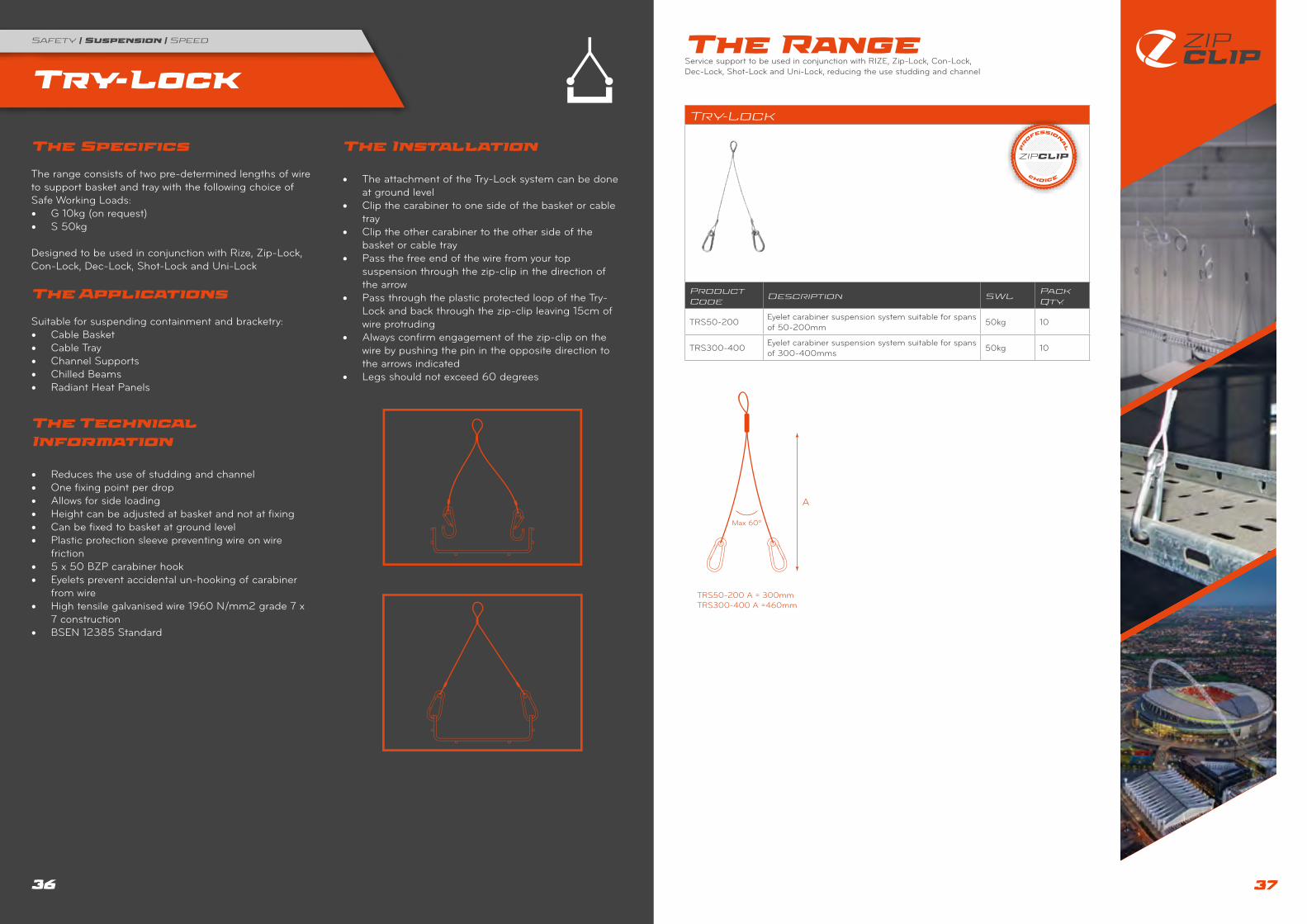
The Installation
• The attachment of the Try-Lock system can be done at ground level
• Clip the carabiner to one side of the basket or cable tray
• Clip the other carabiner to the other side of the basket or cable tray
• Pass the free end of the wire from your top suspension through the zip-clip in the direction of the arrow
• Pass through the plastic protected loop of the Try-Lock and back through the zip-clip leaving 15cm of wire protruding
• Always confirm engagement of the zip-clip on the wire by pushing the pin in the opposite direction to the arrows indicated
• Legs should not exceed 60 degrees
The Range Service support to be used in conjunction with RIZE, Zip-Lock, Con-Lock, Dec-Lock, Shot-Lock and Uni-Lock, reducing the use studding and channel
Try-Lock
Product Code
Description SWLPack Qty.
TRS50-200 Eyelet carabiner suspension system suitable for spans of 50-200mm 50kg 10
TRS300-400 Eyelet carabiner suspension system suitable for spans of 300-400mms 50kg 10
38 39
Luma-Lock
Safety | Suspension | Speed
The Specifics The range consists of pre-determined lengths of wire for the installation of primary and secondary installations with a choice of Safe Working Loads:• G 10kg SWL• S 35kg SWL
Designed to be used in conjunction with Rize, Zip-Clip, Con-Lock, Dec-Lock, Shot-Lock and Uni-Lock
The Applications
Suitable for primary and secondary support for suspending:• Lighting Fittings• Heat Panels• Plenum Boxes• Basket, Ladder and Tray
The Technical Information
• Reduces the use of studding and channel• One fixing point per drop• Can be fixed to installation at ground level• High tensile galvanised wire 1960N/mm² grade 7 x 7
construction• BSEN 12385 Standard
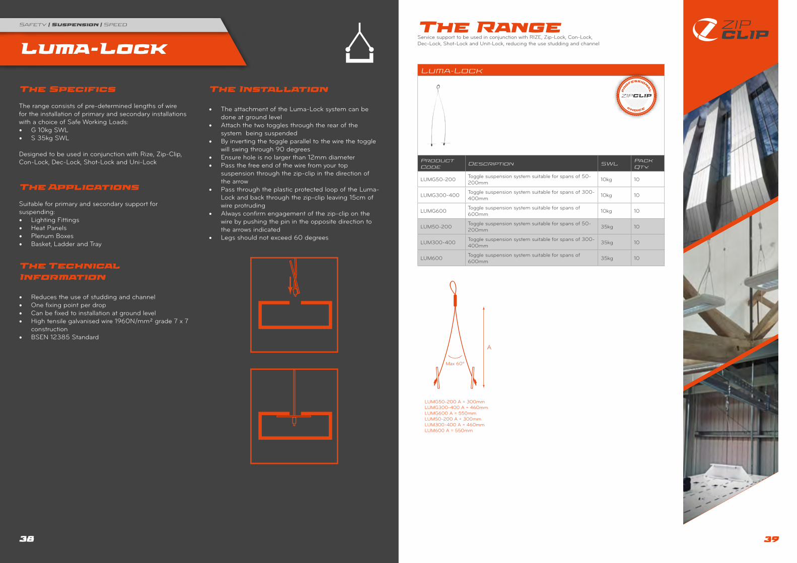
The Installation
• The attachment of the Luma-Lock system can be done at ground level
• Attach the two toggles through the rear of the system being suspended
• By inverting the toggle parallel to the wire the toggle will swing through 90 degrees
• Ensure hole is no larger than 12mm diameter• Pass the free end of the wire from your top
suspension through the zip-clip in the direction of the arrow
• Pass through the plastic protected loop of the Luma-Lock and back through the zip-clip leaving 15cm of wire protruding
• Always confirm engagement of the zip-clip on the wire by pushing the pin in the opposite direction to the arrows indicated
• Legs should not exceed 60 degrees
The Range Service support to be used in conjunction with RIZE, Zip-Lock, Con-Lock, Dec-Lock, Shot-Lock and Unit-Lock, reducing the use studding and channel
Luma-Lock
Product Code
Description SWLPack Qty.
LUMG50-200 Toggle suspension system suitable for spans of 50-200mm 10kg 10
LUMG300-400 Toggle suspension system suitable for spans of 300-400mm 10kg 10
LUMG600 Toggle suspension system suitable for spans of 600mm 10kg 10
LUM50-200 Toggle suspension system suitable for spans of 50-200mm 35kg 10
LUM300-400 Toggle suspension system suitable for spans of 300-400mm 35kg 10
LUM600 Toggle suspension system suitable for spans of 600mm 35kg 10

40 41
Y-It
Safety | Suspension | Speed The Range The system consists of a predetermined length of wire with a second ferruled leg and a choice of either carabiner or toggle ends.
Y-It
Product Code
Description SWLPack Qty.
YTR1S/300 1 Mtr x 300mm eyelet carabiner suspension system 50kg 10
YTR2S/300 2 Mtr x 300mm eyelet carabiner suspension system 50kg 10
YTR3S/300 3 Mtr x 300mm eyelet carabiner suspension system 50kg 10
YTR1S/460 1 Mtr x 460mm eyelet carabiner suspension system 50kg 10
YTR2S/460 2 Mtr x 460mm eyelet carabiner suspension system 50kg 10
YTR3S/460 3 Mtr x 460mm eyelet carabiner suspension system 50kg 10
YTR1Y/300 1 Mtr x 300mm eyelet carabiner suspension system 90kg 10
YTR2Y/300 2 Mtr x 300mm eyelet carabiner suspension system 90kg 10
YTR3Y/300 3 Mtr x 300mm eyelet carabiner suspension system 90kg 10
YTR1Y/460 1 Mtr x 460mm eyelet carabiner suspension system 90kg 10
YTR2Y/460 2 Mtr x 460mm eyelet carabiner suspension system 90kg 10
YTR3Y/460 3 Mtr x 460mm eyelet carabiner suspension system 90kg 10
YLM1G/300 1 Mtr x 300mm toggle suspension system 10kg 10
YLM2G/300 2 Mtr x 300mm toggle suspension system 10kg 10
YLM3G/300 3 Mtr x 300mm toggle suspension system 10kg 10
YLM1G/600 1 Mtr x 600mm toggle suspension system 10kg 10
YLM2G/600 2 Mtr x 600mm toggle suspension system 10kg 10
YLM3G/600 3 Mtr x 600mm toggle suspension system 10kg 10
YLM1S/300 1 Mtr x 300mm toggle suspension system 35kg 10
YLM2S/300 2 Mtr x 300mm toggle suspension system 35kg 10
YLM3S/300 3 Mtr x 300mm toggle suspension system 35kg 10
YLM1S/460 1 Mtr x 460mm toggle suspension system 35kg 10
YLM2S/460 2 Mtr x 460mm toggle suspension system 35kg 10
YLM3S/460 3 Mtr x 460mm toggle suspension system 35kg 10
YLM1Y/300 1 Mtr x 300mm toggle suspension system 90kg 10
YLM2Y/300 2 Mtr x 300mm toggle suspension system 90kg 10
YLM3Y/300 3 Mtr x 300mm toggle suspension system 90kg 10
YLM1Y/460 1 Mtr x 460mm toggle suspension system 90kg 10
YLM2Y/460 2 Mtr x 460mm toggle suspension system 90kg 10
YLM3Y/460 3 Mtr x 460mm toggle suspension system 90kg 10
The Specifics The range consists of a pre-determined length of wire from 1 metre to 3 metres with a choice of Safe Working Load:Carabiner end:• S 50kg SWL• Y 90kg SWLToggle end:• G 10kg SWL• S 35kg SWL• Y 90kg SWL
The system consists of a pre-determined length of wire with a second ferruled leg and a choice of either carabiner or toggle ends.
The Applications
Carabiner end:• Cable basket• Cable tray• Channel supports• Chilled beams• Radiant heat panelsToggle end:• Lighting fittings• Heat panels• Plenum boxes• Basket, ladder and tray
The Technical Information
• Key free release system• High tensile galvanised wire 1960N/mm² grade 7 x 7
construction• BSEN 12385 standard• One fixing point per drop• Allows for side loading• Can be fixed at ground level• Reduces the use of studding and channel• Ideal for short suspensions
The Installation
Installing the carabiners:• Clip one carabiner to one side of the basket or tray to
be suspended• Clip the other carabiner to the other side of the
basket or trayInstalling the toggles:• Attach the two toggles to the rear of the system
being suspended• By inverting the toggle parallel to the wire the toggle
will swing through 90 degrees• Ensure hole is no larger than 12mm diameter
• Pass the free end of the wire through the zip-clip in the direction of the arrow
• Pass through or around your required suspension point and back through the zip-clip leaving 15 cm of wire protruding.
• Always confirm engagement of the zip-clip on the wire by pushing the pin in the opposite direction to the arrows indicated

42 43
Span-Lock
Safety | Suspension | Speed
The Specifics Span-Lock and Zip-Grip are designed to be used in conjunction so as to create a complete catenary system.
Span-Lock is available in 5, 10, 15, 20, 30 and 40 metre lengths, with a choice of Safe Working Loads: • Y 30kg SWL• P 75kg SWL• N 100kg SWL
The Applications
Suitable for:• Lighting• Lighting trunking• Bus bar• Radiant heat panels• Fabric Ducting• Signage• Lightweight ductwork
The Technical Information
• Key free release system• Designed to traverse between two fixed anchor
points• Safe on-site installation, no channel cutting or hot
work permit required• Simple and easy to handle and transport• Comes with two locking mechanisms• Suitable for applications where no overhead fixing
points are available.
Zip-Clip is able to offer a comprehensive catenary calculation service. Please contact our technical team on +44 1686 623366 for more information
When fixing from purlins, always consult with the purlin manufacturer to advise loading capabilities, in conjunction with using the Zip-Clip calculation service.
The Installation
• Secure each end of the Span-Lock wire to a fixed anchor point using the zip-clips supplied
• Pass the wire through the zip-clip in the direction of the arrow
• Pass through or around your required suspension and back through the zip-clip leaving 15cm of wire protruding
• Use a tensioning tool to apply tension to the wire• Always confirm engagement of the zip-clip on the
wire by pushing the pin in the opposite direction to the arrows indicated
The Range Span-Lock and Zip-Grip are designed to be used in conjunction to create a complete catenary system.
Span-Lock
Product Code
Description SWLPack Qty.
GLHCS5Y 5 Mtr horizontal suspension system 30kg 1
GLHCS10Y 10 Mtr horizontal suspension system 30kg 1
GLHCS15Y 15 Mtr horizontal suspension system 30kg 1
GLHCS20Y 20 Mtr horizontal suspension system 30kg 1
GLHCS30Y 30 Mtr horizontal suspension system 30kg 1
GLHCS40Y 40 Mtr horizontal suspension system 30kg 1
GLHCS5P 5 Mtr horizontal suspension system 75kg 1
GLHCS10P 10 Mtr horizontal suspension system 75kg 1
GLHCS15P 15 Mtr horizontal suspension system 75kg 1
GLHCS20P 20 Mtr horizontal suspension system 75kg 1
GLHCS30P 30 Mtr horizontal suspension system 75kg 1
GLHCS40P 40 Mtr horizontal suspension system 75kg 1
GLHCS5N 5 Mtr horizontal suspension system 100kg 1
GLHCS10N 10 Mtr horizontal suspension system 100kg 1
GLHCS15N 15 Mtr horizontal suspension system 100kg 1
GLHCS20N 20 Mtr horizontal suspension system 100kg 1
GLHCS30N 30 Mtr horizontal suspension system 100kg 1
GLHCS40N 40 Mtr horizontal suspension system 100kg 1
Ensure a distance of at least 1.6 x the height of the beam is left between the zip-clip and the structure. Do not exceed an angle of 60°

44 45
Zip-Grip
Safety | Suspension | Speed
The Specifics Span-Lock and Zip-Grip are designed to be used in conjunction so as to create a complete catenary system.
Zip-Grip is available in 1 to 10 metre lengths, with a choice of Safe Working Loads:• G 10kg SWL• S 35kg SWLAvailable in M6 to fit Y and P Span-lock range and M8 to fit the N range
The Applications
Suitable for:• Lighting• Ligthing trunking• Bus bar• Radiant heat panels• Signage • Fabric ducting• Lightweight ductwork
The Technical Information
• Key free release system• Simple hook and lock system• Ability to suspend many products, even at angles• Easy slide for adjustment into final position• Can be fitted retrospectively up to the SWL• Can be simply inverted to offer extra support to the Span-
Lock range• Suitable for applications where no overhead fixing points
are available
The Installation
• Place the Zip-Grip onto the tightened wire and slide into place
• Tighten the eye until engaged on the Span-Lock wire, then tighten the locking nut to secure place
• Pass the free end of the wire through the supplied zip-clip around the object to be suspended then back through the zip-clip
• Pass the wire through the zip-clip in the direction of the arrow
• Pass through or around your required suspension and back through the zip-clip leaving 15cm of wire protruding
• Height can then be adjusted• To reduce deflection in the wire the Zip-Grip can be
inverted and fixed from the structure above• Always confirm engagement of the zip-clip on the wire
by pushing the pin in the opposite direction to the arrows indicated
The Range Span-Lock and Zip-Grip are designed to be used in conjunction to create a complete catenary system.
Zip-Grip
Product Code
Description SWLPack Qty.
GLG1 1 Mtr vertical suspension system M6 10kg 10
GLG2 2 Mtr vertical suspension system M6 10kg 10
GLG3 3 Mtr vertical suspension system M6 10kg 10
GLG4 4 Mtr vertical suspension system M6 10kg 10
GLG5 5 Mtr vertical suspension system M6 10kg 10
GLG10 10 Mtr vertical suspension system M6 10kg 10
GLS1 1 Mtr vertical suspension system M6 35kg 10
GLS2 2 Mtr vertical suspension system M6 35kg 10
GLS3 3 Mtr vertical suspension system M6 35kg 10
GLS4 4 Mtr vertical suspension system M6 35kg 10
GLS5 5 Mtr vertical suspension system M6 35kg 10
GLS10 10 Mtr vertical suspension system M6 35kg 10
GLG1/M8 1 Mtr vertical suspension system M8 10kg 10
GLG2/M8 2 Mtr vertical suspension system M8 10kg 10
GLG3/M8 3 Mtr vertical suspension system M8 10kg 10
GLG4/M8 4 Mtr vertical suspension system M8 10kg 10
GLG5/M8 5 Mtr vertical suspension system M8 10kg 10
GLG10/M8 10 Mtr vertical suspension system M8 10kg 10
GLS1/M8 1 Mtr vertical suspension system M8 35kg 10
GLS2/M8 2 Mtr vertical suspension system M8 35kg 10
GLS3/M8 3 Mtr vertical suspension system M8 35kg 10
GLS4/M8 4 Mtr vertical suspension system M8 35kg 10
GLS5/M8 5 Mtr vertical suspension system M8 35kg 10
GLS10/M8 10 Mtr vertical suspension system M8 35kg 10
M8M6

46 47
H-Frame
Safety | Suspension | Speed
The Specifics The Zip-Clip H-Frame systems are designed to fit UNISTRUT channel and has a cross compatibility with all UNISTRUT type brackets.• H-Frame 700kg/kit SWL• Base Frame 700kg/kit SWL• Extender Frame 350kg/kit SWL
A range of roofing supports designed for AHUs without penetrating the roof membrane
The Applications
Suitable for:• Suitable for:• Roof mounted services• Cable tray• Cable Basket
The Technical Information
• No penetration of waterproof membrane• Anti vibration pads attached to feet• Easy to install and adapt• High Density Polyethylene• Each foot is made from a linear Polymer, High
Density Polyethylene (HDPE) and is prepared from euthylene by a catalytic process
• The absence of branching results in a more closely packed structure with a higher chemical resistance than LDPE.
• HDPE is harder and more opaque and can withstand higher temperatures (120°C for short periods, 110°C continuously)
The Installation
The Range A range of roofing supports designed for AHUs without penetrating the roof membrane.
H-Frame
Product Code
Description SWLPack Qty.
FRS-HF Flexi H-Frame 700kg/kit
FRS-BF Flexi Base Frame 700kg/kit
FRS-EF Flexi Extender Frame 350kg/kit
H-Frame Base
Plus Base + Plus

48 49
Accessories
Safety | Suspension | Speed
ImageProduct Code
Description Pack Qty.
CUT1 Heavy Duty Wire Cutters 1
CUT3 Heavy Duty Cutters for P Wire 1
TT1 Tensioning Tool 1
CPA1 Corner Protector 50
CPA1MAG Magnetic Corner Protector 50
CH1 Chan-Lock Hanger 10
AC10 2 Way Screw Down Locking Device 8kg SWL 3:1 SF 10
UNI1 M6 x 20mm Universal Eyebolt with Flange Nut 10
UNI2 M6 x 45mm Universal Eyebolt with Flange Nut 10
UNI3 M8 x 25mm Universal Eyebolt with Flange Nut 10
UNI6M60 M6 x 60mm Closed Eyebolt 10
UNI8M60 M8 x 60mm Closed Eyebolt 10
UNI10M60 M10 x 60mm Closed Eyebolt 10
ATLDM6 M6 Standard Drop In Anchor 10
ATLDM8 M8 Standard Drop In Anchor 10
ATLDM10 M10 Standard Drop in Anchor 10
ATLDM6/ST Standard Setting Tool for M6 Drop in Anchor 1
ATLDM8/ST Standard Setting Tool for M8 Drop in Anchor 1
ImageProduct Code
Description Pack Qty.
ATLDM10/ST Standard Setting Tool for M10 Drop in Anchor 10
PVC100S PVC 100M Reel x 3mm Ø 1
PVC100P PVC 100M Reel x 6mm Ø 1
HCB1 90 degree bracket with 7.0mm and 5.0mm hole, 1.3mm gauge 10kg SWL 10
HCB2 90 degree bracket with 7.0mm and 5.0mm hole, 1.3mm gauge 50kg SWL 10
HCB3 90 Degree bracket with 6.5mm holes, 2.0mm gauge 90kg SWL 10
MA6810 Multiwedge Decking Fixing 10
MA300HEX 300mm Magnetic Bit Holder for MA6810 1
CLA1 Universal Concrete Anchor 50
CLA2 Concrete Spike 50
T920514 Vertical Flange Clip 1-5mm 10
T920515 Vertical Flange Clip 5-7mnm 10
HCBP1 Shot Fired Fastener for Concrete and Steel 10
SFN19 19mm Ballistic Point Nail 100
SFN27 27mm Ballistic Point Nail 100
SFSCG Powder Actuated Cartridge - Low Power 100
SFSCY Powder Actuated Cartridge - Medium Power 100
SFSCR Powder Actuated Cartridge - High Power 100

50 51
Prefabrication
Safety | Suspension | Speed
Zip-Clip are able to offer a free of charge drawing calculation service
Step 1:E-mail your drawing to [email protected]
Step 2:Our technical department will contact you with a few simple questions
Step 3:A full recommendation and quotation will follow. A unique project drawing number will be issued for reference.
The Zip-Clip Drawing Calculation Service is proving to be a big success with contractors.
ON-SITE PULL TESTS
To add peace of mind to our already independently tested systems we offer an on-site pull test which will be validated and certified by . With so many variants in concrete (ie flint, pebbles...), this unique free service is very reassuring.
Calculation Services
Safety | Suspension | Speed
Specialist Applications
Zip-Clip Ltd is renowned for its unique problem solving solutions. Over the past number of years we have designed and developed a range of systems tailored to overcome troublesome applications. With our highly trained technical managers and our extensive knowledge of the fixings market we can confidently design a solution for your requirements. Examples of our abilities are as below:
TUNNEL SOLUTION
A solution was found for the Hatfield and Hindhead road tunnels for the suspension of a linear heat detection cable. The solution was required as the linear cable did not travel in a straight line due to the ventilation and lighting equipment in its path. Zip-Clip were able to develop a bespoke low carbon stainless steel solution designed for this harsh environment that could be installed quickly with minimum disruption.
INTERNALLY CLADDED BUILDINGS
With the increasing number of internally cladded buildings being specified, finding a suitable anchor point is not always possible. Zip-Clip designed a solution for the Pirelli Tyre Distribution Centre in Burton-on-Trent by utilising a unique self tapping anchor which did not affect the integrity of the cladding.
Zip-Clip is able to provide special products for many applications. Among others:• Seismic areas• Christmas decorations• Acoustic supports• Pest control• Museum installations
Each drawing is tailored for specific needs. A unique number is attributed to each drawing, allowing ease of re-ordering and product continuity.
Architectural Supports
Safety | Suspension | Speed
Zip-Clip also supplies a full range of aesthetically pleasing cable supports. The systems are safe and easy to use with finger tip adjustment for precise height adjustment with no tools required. The product is ideal for supporting lighting systems, cable management, store displays and signage.
SPECIALIST SUPPORT BRACKETS
Zip-Clip have developed a number of specialist brackets to enable the installer to suspend both HVAC and M & E services as quickly as possible. Zip-Clip designed these systems to not only speed up installations but also to reduce the need for assembly on site. These support brackets can also be used in conjunction with modular designed systems.
A brief example of the large number of designed brackets include:
PIPE BRACKET:This can be designed to your specification for suspending both pipe work and cable tray from one anchor point
BRACE BRACKET:This bracket can be used as a primary installation or as a retrofit solution. The brackets can be used in conjunction with a choice of anchors

52 53
Specifications
Safety | Suspension | Speed
Specifications
Safety | Suspension | Speed
PHYSICAL PROPERTIES
Density 6,700kg/m³ at 21°C
Solidification Shrinkage 1.17%
Casting Shrinkage 0.6% (pressure diecasts)
Freezing Range -381 to -387°C
Melting Point 400 to 420°C
Specific Heat Capacity 418.1 J/kg/°C at 20 to 100°C
Thermal Expansion 27 10 (-6) linear per °C at 20 to 100°C
Thermal Conductivity 108.9 W/m/hr/m2/°C at 70 to 140°C
Electrical Conductivity 26% IACS
Electrical Resistivity 6.5359 um ohm cm at 20°C
MECHANICAL PROPERTIES
As Cast Aged
Tensile Strength (MPa) 328 269
Shear Strength (MPa) 262 -
Elongation (% in 51mm) 7 13
Hardness (Brinell – 500kg) 91 80
Impact Strength (Energy, Joules) 65.1 54.2
Fatigue Strength 5 x 10 cycles (MPa) 56.5 -
TYPICAL ANALYSIS – ALLOYING ELEMENTS
Aluminium 4%
Copper 1%
Magnesium 0.05%
TYPICAL ANALYSIS - IMPURITIES
Iron < 0.01%
Lead < 0.003%
Cadmium 0.003%
Tin < 0.001%
Nickel <0.001%
Silicon < 0.01%
Galvanised Wire
Wire Code MBL of Wire Rope Construction Tensile Strength
G 78kg 7x7 (6/1) RHRL 1960N/mm²
S 290kg 7x7 (6/1) RHRL 1960N/mm²
Y 645kg 7x7 (6/1) RHRL 1960N/mm²
P 1240kg 7x19 (6/1) RHRL 1960N/mm²
N 2804kg 7x19 (6/1) RHRL 1960N/mm²
Stainless Steel Wire
Wire Code SWL of Wire Rope GRADE
G 8kg AISI 316
S 45kg AISI 316
Y 100kg AISI 316
P 200kg AISI 316
Angular Performance
The table below shows the effect on the Safe Working Load when working at an angle from the vertical when using the professional choice range.
Wire Code Vertical 15° 30° 45° 60°
G 10kg 9.6kg 8.6kg 7.0kg 5.0kg
S 50kg 48.0kg 43.0kg 35.0kg 25.0kg
Y 120.0kg 115.2kg 103.2kg 84.0kg 60.0kg
P 230kg 220.8kg 197.8kg 161.0kg 115.0kg
LOAD 100% 96% 86% 70% 50%
The high tensile wire we supply is galvanised and manufactured to the highest standards incorporating a 7 x 7 construction, meeting the BSEN 12385 standard.
BSMA 29/1983 standard also meeting the AISI 3136 requirements
The diagram to the left shows the construction of the 7x7 wire braids.
The diagram to the right shows the construction of the 7 x 19 wire braids.

54
Zip-Clip Ltd recognizes that its activities impact on the environment at local, regional and global levels and acknowledges a responsibility for the protection of the environment and of the health and safety of its employees and the wider community
Zip-Clip Ltd Is Committed To:• Promoting the protection of the environment and minimizing the impact of all its activities upon each of the local,
regional and global environments both directly and through its influence on others.• Contributing to a sustainable and healthy future by conserving natural resources and by minimizing avoidable waste
and pollution.• Reducing the use of fossil fuels through improvements to energy efficiency and the substitution of renewable energy
resources.• Developing effective waste management and recycling procedures and using recycled and recyclable materials where
possible.• Increasing awareness of environmental responsibilities amongst staff.
To Achieve These Goals We Will:• Educate and train staff in environmental matters as appropriate.• Progressively reduce the amount of waste generated.• Market products, which create a minimum environmental damage, and use its purchasing to influence to:
» Promote production of such products. » Ensure that all public communications are true and unambiguous. » Respect the interests of neighbours and the world community. » Review our policies as an ongoing matter.
Environment
Safety | Suspension | Speed

Zip-Clip Ltd, Offas Dyke Business Park, Welshpool, Powys, SY21 8SS, United Kingdom
+44 (0) 1686 623 366
+44 (0) 1686 623 377
www.zip-clip.comZCTC0317V1