issue 1 march 2002 - fiber optic cables, connectors...
TRANSCRIPT

SC Product Specification Issue 1 March 2002

SC Product Specification Issued: April, 2002 i
SC Product Specification General Definition: The SC Connector Product is a robust optical connector designed to support Telecom and Datacom networks. The connector family includes but not limited to connectors, adapters, attenuators, modular adapters, jumpers, an assortment of connector modules and panels, and installation tool kits and consumable kits. The OFS SC Connector is a push-pull connector that uses 4-position tuning, which can be accomplished by simply rotating the grip 90 degrees. This high performance SC connector is versatile for both singlemode and multimode applications. Terms of Specification: The specification document is intended to provide users of OFS Fitel SC Connector products a level of confidence and means of understanding the characteristics of purchased product. The product is designed and should be manufactured according to the specification document. The product specification serves as a guideline to the features and performance of the product, and is subject to change without notice. Definition of Products: SC Jumper Connectors: Robust family of connectors designed to mount on 1.6 – 3.0 mm fiber cordage and intended to meet the Telcordia GR-326-CORE, Issue 3, for Type I Media (reinforced jumper cordage). SC BTW Connectors: SC connectors designed for 900 micron buffered fiber. This product is intended to meet Telcordia GR-326-CORE, Issue 3 for Type II Media (900 micron buffered fiber). SC Jumpers: Connectorized 1.6mm and 3.0mm cordage in various lengths and fiber counts. Jumpers are produced in a vast array of hybrid configurations allowing interconnection between SC based product and other connector styles. These products are intended to meet Telcordia GR-326-CORE, Issue 3 for Type I Media. SC Adapters: Two-port configuration for joining two SC connectors. The adapter contains the alignment sleeve for the precise alignment of the connector ferrules. Available in simplex, duplex and higher density configurations based on application needs. See also 0dB Modular Adapters. SC Modular Adapters & Attenuators: Attenuator products are configured as a Build-On style or a Modular Adapter. The Type II Modular Adapters consist of single port adapters configured from 2 parts: a base and a cap. Two bases are available: SC or ST? . The cap is available in 3 connector versions, SC, ST® and FC and in 0-dB and attenuated values. Build-On Attenuators are one-piece designs that combine an SC Connector on one end and an adapter on the other, and are available in several attenuation values. Each attenuator product reduces optical power internally. SC-LC Converter: The “in-line” converter is a combination of an SC connector and an LC receptacle. This essentially allows an LC connector to mated into an SC adapter. Product Identification: SC products are easy to identify in accordance with industry standards:
Blue represents singlemode Beige represents multimode Green represents singlemode APC (Angled End Face) A & B port identification is on duplex adapters in accordance with TIA 568
? ST is a registered trademark of OFS Fitel

SC Product Specification Issued: April, 2002 ii
Revision History
Date Rev. Name Comments
4/5/2002 Issue 1 TBM Initial Release

SC Product Specification Issued: April, 2002 iii
Table of Contents 1.0 – SC CONNECTOR SPECIFICATION............................................................................................ 1
1.1 – SC Connector Application ...................................................................................................... 2 1.2 – SC Connectors: Exploded View.............................................................................................. 2
1.2a – SC Jumper Connectors .................................................................................................... 2 1.2b – SC BTW (Behind the Wall) Connector ............................................................................... 2
1. 3 – SC Connector Footprint Dimensions ...................................................................................... 3 1.4 – SC Connector Materials......................................................................................................... 3 1.5 – SC Connector Illustrations...................................................................................................... 4
1.5a – SC Simplex Connector..................................................................................................... 4 1.5b – SC Duplex Connector ...................................................................................................... 4 1.5c – SC Connector Specifications for Intermateability................................................................. 5
1.6 – Ferrule Surface Requirements ................................................................................................ 6 1. 7 – SC Connector Ferrule Extension and Contact Force................................................................ 7 1.8 – SC Connector Coding (or equivalent)....................................................................................... 7 1.9 – SC Connector Color Coding.................................................................................................... 7
2.0 – SC ADAPTER SPECIFICATION................................................................................................. 8 2.1 – SC Simplex and Duplex Adapter: Iso View .............................................................................. 9
2.1a – SC Duplex Adapter 2.1b – SC Simplex Adapter .......................................... 9 2.2 – SC Adapter Footprint Dimensions ........................................................................................... 9
2.2a – SC Duplex Adapter 2.2b – SC Simplex Adapter ............................................ 9 2.3 – Panel Cutout Dimensions for Mounting SC Adapters .............................................................. 10 2.4 – SC Adapter Materials .......................................................................................................... 10 2.5 – SC Adapter Illustrations ....................................................................................................... 11
2.5a – SC Simplex Adapter ...................................................................................................... 11 2.5b – SC Duplex Adapter........................................................................................................ 12 2.5c – SC Adapter Specifications for Intermateability .................................................................. 12
2.6 – SC Adapter Coding Scheme................................................................................................. 13 2.7 – SC Adapter Color Coding ..................................................................................................... 13
3.0 –MODULAR ADAPTERS AND ATTENUATORS........................................................................... 14 3.1 – Modular Adapter System (UBO): Exploded View.................................................................... 15 3.2 – Modular Adapter SC “.......................................................................................................... 16 3.3 – Modular Adapter ST “Base” Footprint .................................................................................... 16 3.4 – Modular Adapter SC “Cap” Footprint...................................................................................... 17 3.5 – Modular Adapter and Attenuator System Materials and Specifications ..................................... 17 3.6 – Modular Adapter “Base” Coding Scheme ............................................................................... 18 3.7 – Modular Adapter “Cap” Coding Scheme................................................................................. 18 3.8 – ASCS Series Modular Attenuator “Caps”............................................................................... 18 3.9 – ASCM Series Modular Attenuator “Caps”............................................................................... 21 3.10 – ASCLR Series Modular Attenuator “Caps”............................................................................ 22 3.11 – A3060N1 Series Modular Attenuator “Caps”......................................................................... 22 3.12 – Modular Adapter Spectral Flatness ..................................................................................... 23 3.13 – Modular Adapter Power Divergence..................................................................................... 23 3.14 – Modular Adapter Compliance to GR-910 and GR-326............................................................ 24
4.0 – SC BUILD-ON ATTENUATORS ............................................................................................... 25 4.1 – Build-On Attenuator System Application................................................................................ 26 4.2 – Build-On Attenuator Footprint Illustration ............................................................................... 26 4.3 – Build-On Attenuator Materials and Specifications ................................................................... 27

SC Product Specification Issued: April, 2002 iv
4.4 – Build-On Attenuator Coding Scheme..................................................................................... 27 4.5 – ABSCS Series Build-on Attenuator ....................................................................................... 28 4.6 – ABSCA Series Build-on Attenuator ....................................................................................... 28
5.0 – SC TERMINATOR SPECIFICATION......................................................................................... 29 5.1 – SC Terminator Application.................................................................................................... 30 5.2 – Terminator Information and Performance................................................................................ 30
6.0 – SC-LC CONVERTER............................................................................................................... 31 6.1 – SC-LC Converter Application ................................................................................................ 32 6.2 – SC-LC Converter Footprint Illustration.................................................................................... 32 6.3 – SC-LC Converter Information and Performance....................................................................... 32
7.0 – SC JUMPER SPECIFICATION................................................................................................. 33 7.1 – SC Simplex Jumper............................................................................................................. 34 7.2 – SC Simplex Jumper Exploded Assembly............................................................................... 34 7.3 – SC Duplex Jumper Exploded Assembly ................................................................................ 35 7.4 – SC Duplex MM Jumper as per TIA/EIA .................................................................................. 35 7.5 – SC Jumper/Connector Materials ........................................................................................... 36 7.6 – Cordage Technical Specifications ......................................................................................... 36 7.7 – SC Singlemode Ferrule Endface Geometry ............................................................................ 37 7.8 – SC APC Ferrule End-face Geometry ..................................................................................... 38 7.9 – SC APC Ferrule/Angle Orientation ........................................................................................ 39 7.10 – SC Factory Made PC Patch Cord – Specifications ............................................................... 39 7.11 – Visual Inspection Criteria for Fiber Optic Connectors with Fiber.............................................. 40 7.12 – SC SM Jumper Tuning Configuration ................................................................................... 41 7.13 – SC Jumpers – Available Configurations ................................................................................ 42 7.14 – SC Jumper Coding Scheme................................................................................................ 43 7.15 – SC Jumper Color Coding .................................................................................................... 43
8.0 – SC TOOLS, KITS, AND CONSUMABLES................................................................................. 44 8.1 – Ordering Information ............................................................................................................ 45

SC Product Specification Issued: April, 2002 1
1.0 – SC Connector Specification
SC Product Specification Issued: April, 2002 2
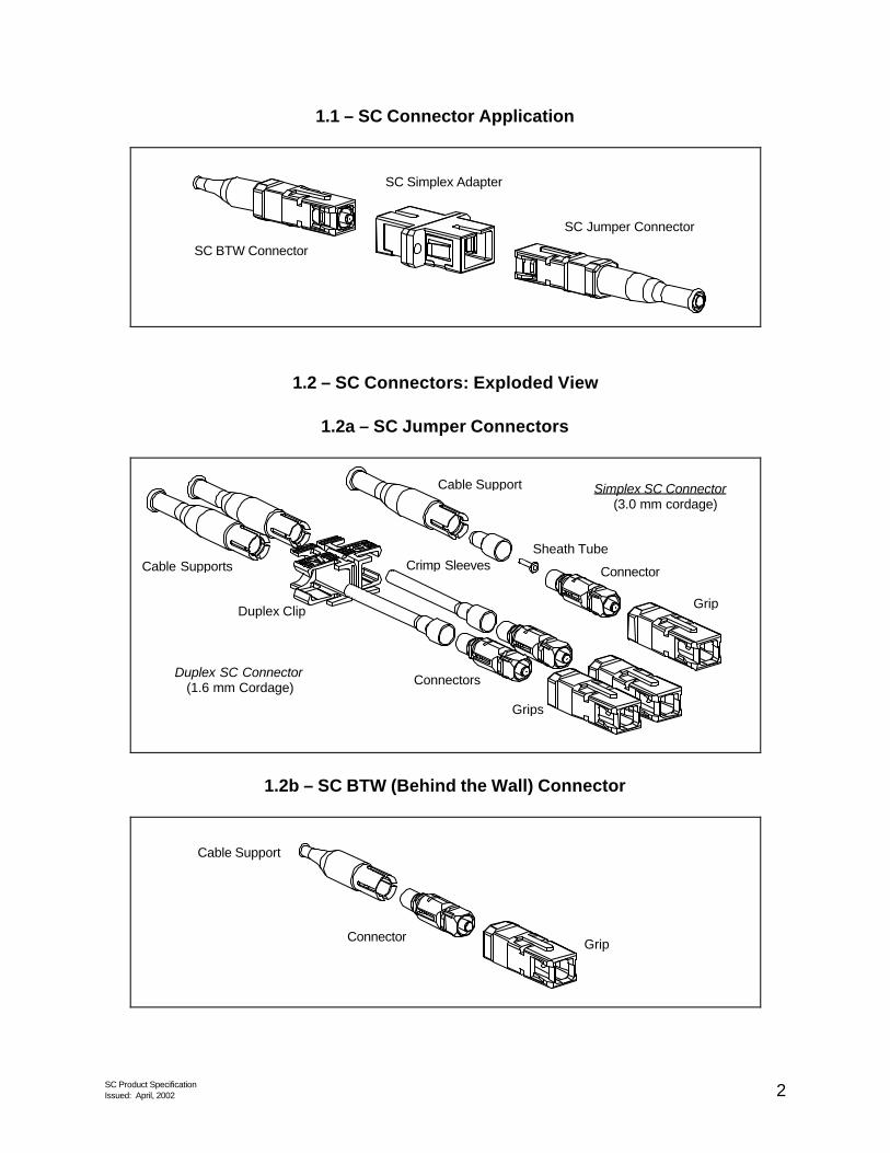
1.1 – SC Connector Application
SC Jumper Connector
SC BTW Connector
SC Simplex Adapter
1.2 – SC Connectors: Exploded View
1.2a – SC Jumper Connectors
Sheath Tube
Connector
Cable Support
Duplex Clip Grip
Duplex SC Connector (1.6 mm Cordage)
Simplex SC Connector (3.0 mm cordage)
Cable Supports
Grips
Connectors
Crimp Sleeves
1.2b – SC BTW (Behind the Wall) Connector
Connector
Cable Support
Grip

SC Product Specification Issued: April, 2002 3
1. 3 – SC Connector Footprint Dimensions
C F
E
D
B
A
BTW Connector Jumper Connector
REF. DIMENSIONS
Minimum mm Maximum A 0.9 1.0 B - 56 C - 58 D 1.8 3.2 E - 58 F - 60
1.4 – SC Connector Materials
Connector Part
Material
UL 94 Rating
Oxygen Index
Ferrule Zirconia - - Barrel Stainless Steel - - Cable Support Boot Engineering Plastics V-0 29 Spring Stainless Steel - - Plug Frame Engineering Plastics V-0 34 Duplex Clip Engineering Plastics V-0 35 Grip Engineering Plastics V-0 34 Buffer Boot Engineering Plastics V-0 29 Cable Retention Member Ni-plated Brass - - Crimp Sleeve Anodized Aluminum - - Sheath Tube Ni-plated Brass - -

SC Product Specification Issued: April, 2002 4
1.5 – SC Connector Illustrations
1.5a – SC Simplex Connector
1.5b – SC Duplex Connector
Z

SC Product Specification Issued: April, 2002 5
1.5c – SC Connector Specifications for Intermateability
Dimensions (mm.) Ref. Min. Max.
Notes
A 2.4985 2.4995 B 4.8 4.9 C 6.8 7.4 D - 5.3 E 6.7 6.8 F 19° 23° G 25° 35° H 7.15 7.85 1, 2 I 0.8 1.2 J 5.3 5.5 K - 0.05 3 L 2.11 - 4 M 2.0 2.8 4 N 6.6 6.8 O 1.6 1.8 P 8.79 8.99 Q 0.8 1.0 R 7.19 7.39 S - 0.9 Radius T 4.05 4.15 U 5.4 - V -0.5 0.57 3
BC 0 0.5 Chamfer Z 12.7 5
Notes: 1. Ferrule compression force shall be from 7,8 N to 11,8 N, when the ferrule is compressed to a point
where H is 7,00 ? 0,1 mm. 2. This value shows the dimension after the ferrule is polished and in the unmated condition. 3. The negative dimension refers to the position of the inside bottom plane left – direction relative to the
mechanical reference plane 4. The coupling sleeve can move in both the right and left directions to engage the adapter. Dimension M
is measured when the coupling sleeve is in its extreme right position. 5. Each of the units in the duplex connector shall comply with all of the dimensions in Figure 1.5a. 6. Where a tolerance of form is not specified, the limits of the dimensions for a feature control the form as
well as the size. 7. Where interrelated features of size (features shown with a common axis or center plane) have no
geometric tolerance of location or run out specified, the limits of the dimensions for a feature control the location tolerance as well as the size.
8. Where perpendicular features (features shown at right angles) have no geometric tolerance of orientation or run out specified, the limits of the dimensions for a control the orientation tolerance as well as the size.

SC Product Specification Issued: April, 2002 6
FERRULE
1.6 – Ferrule Surface Requirements
INSPECTION CRITERIA: SINGLEMODE
A Core Zone
Diameter 0 - 25 µm Scratches (SM) None Pits & Chips None Contamination None Crack None Other
B Cladding Zone
Diameter 25 - 120 µm Scratches (SM) Up to 3 scratches of any
length, 1-3 ? m width Pits & Chips Unlimited (<2 ? m dia.) Contamination None Crack None
C Epoxy Zone
Diameter 120 - 130 µm Scratches (SM) Unlimited Pits & Chips Unlimited (<5 µm dia.) Contamination No loose particles
D Contact Zone
Diameter 130 - 250 µm Scratches (SM) Unlimited Pits & Chips Unlimited Contamination No loose particles
INSPECTION CRITERIA: SINGLEMODE_APC same as singlemode above except as noted.
A Core Zone
Scratches Any length, ? 2 ? m width if optical requirements are met
B Cladding Zone
Scratches Any length, ? 2 ? m width
INSPECTION CRITERIA: MULTIMODE same as singlemode above except as noted.
A Core Zone
Diameter 0 - 62 µm
Scratches Any length, ? 2 ? m width if optical requirements are met
B Cladding Zone
Diameter 62 - 120 µm
Scratches Any length, ? 2 ? m width
Magnification (minimum)
Resolving Power
Numerical Aperture
200x
1 µm
0.3
Notes: 1. For optical performance, see Table 5.10 of Factory
Made PC Patch Cord - Specification. 2. Proposed measurement method IEC 86B WG4
61300-3-X dated October 2001. 3. Since loose particles may be introduced during the
inspection process, cleaning the end-face is recommended prior to insertion into the microscope. Cleaning procedures are found in Section 4.3 of Telcordia GR-326-CORE, Issue 3, September 1999.
4. Figure and singlemode Table proposed IEC 86B WG6 Level 2 Specification for polished fiber end faces. Scratches and defects ?1.0 µm are not counted. Dated October 2001, except 2 ?m scratch width & pit diameter was 1 ?m.
5. Outside the 250 ?m contact zone there are no requirements for visual inspection since defects found in this region have no influence on the optical performance of PC polished ferrules.
Figure not-to-scale.
C B
D
A
FIBER

SC Product Specification Issued: April, 2002 7
1. 7 – SC Connector Ferrule Extension and Contact Force
A
F
MECHANICALREFERENCE
PLANE
OPTICALREFERENCE
PLANE
Requirements for ferrule travel and contact force: IF THEN 1 F = 0 A ? 7.15 mm 2 A ? 7.1 mm F ? 7.8 N (800 gf) 3 A ? 6.9 mm F ? 11.8 N (1200 gf)
Note: Dimension A is for finished ends after all polishing has been completed
1.8 – SC Connector Coding (or equivalent)
P 6 2 00 A - Z - 125 | | | | | | |
Plug Series Type Style | Ferrule Hole Size 0-SM 00- 1.6, 2.0, 3.0mm | Z-Zirconia 1-xxx 01- 0.9mm | 2-MM | | | Version
1.9 – SC Connector Color Coding
Connector Housing Color Cable Support Color SM Blue Blue MM Beige White APC Green Green

SC Product Specification Issued: April, 2002 8
2.0 – SC Adapter Specification

SC Product Specification Issued: April, 2002 9
2.1 – SC Simplex and Duplex Adapter: Iso View
2.1a – SC Duplex Adapter 2.1b – SC Simplex Adapter
2.2 – SC Adapter Footprint Dimensions
2.2a – SC Duplex Adapter 2.2b – SC Simplex Adapter
A
D
B
A
D
E
C F
REF. DIMENSIONS (mm) Minimum Maximum
A 9.2 9.4 B - 25.7 C - 35.2 D 27.5 27.7 E - 12.8 F - 22.5

SC Product Specification Issued: April, 2002 10
2.3 – Panel Cutout Dimensions for Mounting SC Adapters
dBE
C
G*
SimplexMounting
DuplexMounting
PanelThickness
A A
F
Dimension Minimum (mm)
Maximum (mm)
A 9.5 10.0 B 13.0 13.5 C 17.9 18.1 E 26.0 26.5 F 30.6 30.8
G* 1.6 1.7 d 2.4 2.6
* Panel thickness “G” applies after surface preparation i.e. painting, etc.
2.4 – SC Adapter Materials
Connector Part Material UL 94 Rating Oxygen Index Adapter Housing Engineering Plastics V-0 28 - 35 Latch Insert Engineering Plastics V-0 46.5 Retaining Clip Stainless Steel - - SM Sleeve Zirconia - - MM Sleeve Phosphor Bronze - -

SC Product Specification Issued: April, 2002 11
2.5 – SC Adapter Illustrations
2.5a – SC Simplex Adapter

SC Product Specification Issued: April, 2002 12
2.5b – SC Duplex Adapter
Z
2.5c – SC Adapter Specifications for Intermateability
Dimensions (mm) Ref. Minimum Maximum
Notes
A diameter, 1 B 4.69 4.79 diameter D 4.9 5.5 H 6.9 7.1 I 0.4 0.8 J 5.51 5.9 K 0.06 1 L 1.9 2.1 O 2.0 2.2 2 P 9.0 9.1 R 7.4 7.5 S 1.0 1.1 T 3.8 4.04 U 5.0 5.3 V 0.6 1.6
AA 27 33 degree AB 0.8 1.0 AC 0.4 0.6 AD 0.7 0.8 AE 0.4 0.6 BA 5.4 5.6 BB 10.8 11.2 Z 12.7
Notes: 1. The connector alignment feature is a zirconia ceramic resilient sleeve, which is free to move in the
adapter. Alternative materials may be used for the sleeve that have directly compatible materials properties with zirconia. The gauge retention force shall be measured with 2 gauge pins, each inserted to the middle of the alignment feature. The gauge retention force shall be from 2,9 N to 5,9 N, for the extraction of one gauge.
2. The position of the two slots “O” shall lie on the same axis. 3. Mechanical Reference Plane

SC Product Specification Issued: April, 2002 13
2.6 – SC Adapter Coding Scheme
C 6 2 0 0 A - 4 | | | | | | |
Adapter Series Type Style | Sleeve Ports 0-MM 6-SC to SC | A-Zirconia 5-Simplex 1-SM 7-SC to ST | B-Metal 4-Duplex 2-APC | Sleeve 0-Zirconia 1-Metal
2.7 – SC Adapter Color Coding
Adapter Housing Color SM Blue MM Beige APC Green

SC Product Specification Issued: April, 2002 14
3.0 –Modular Adapters and Attenuators Universal Build-out (UBO)

SC Product Specification Issued: April, 2002 15
3.1 – Modular Adapter System (UBO): Exploded View
The Modular Adapter System, consisting of a “base”, formally known as a “block”, and a “cap”, formally known as a “build-out”, acts as a split adapter that allows you to standardize your equipment design around one industry connector style, while your customer has the flexibility to choose the connector style that best fit their requirements. With the Modular Adapter System you can easily install attenuators to balance the power output from the transmitter and the system includes two interchangeable components: attenuators and standard caps. For singlemode, single-fiber connections, the SC, ST and FC are currently the most popular 2.5 mm connectors in the communications industry. They are all based on 2.5mm alignment ferrules, usually made of ceramic materials. The size commonality, along with corresponding alignment sleeves, facilitates the mating of these otherwise different connectors. The above picture depicts a few of OFS Fitel’s Modular Adapter System components that permit mix-or-match interconnections.

SC Product Specification Issued: April, 2002 16
3.2 – Modular Adapter SC “
3.3 – Modular Adapter ST “Base” Footprint

SC Product Specification Issued: April, 2002 17
3.4 – Modular Adapter SC “Cap” Footprint
3.5 – Modular Adapter and Attenuator System Materials and Specifications
Connector Part Material UL 94 Rating Oxygen Index Attenuator Cap Engineering Plastic V-0 48 Base Engineering Plastic V-0 48 Attenuator Element Optical Plastic H.B T.B.D Attenuator Sleeve Zirconia - -
Specifications: Units Value Physical SC Split Adapter Type Base Color SC = Blue
ST = White Cap Color AXXS-x.x = Green
AXXM-x.x = Beige/Gray AXXLR-x.x = Light Blue A30x0-x.x = Yellow
Transmission Singlemode Nominal Attenuation @ 1550 nm and 0 dBm dB See table for each type Attenuation Tolerance @ 1550 nm and 0 dBm dB See table for each type Maximum Spectral Attenuation Variation (1300 to 1620 nm) dB See section 3.12 Maximum Attenuation Variation Due to Incident Power dB See section 3.13 Maximum Incident Optical Power Handling Capability dBm 25 Reflectance dB See note below table for each type Operating Temperature °C -40 to 75 Matings over Life 200

SC Product Specification Issued: April, 2002 18
3.6 – Modular Adapter “Base” Coding Scheme
Product Code
Order Comcode
Description
Color
Used With
A3002 106709140 ST Universal Base White
A3003 106750763 SC Universal Base Blue
All SC, ST & FC Universal Build-out
Caps
3.7 – Modular Adapter “Cap” Coding Scheme
A SC S - 3.0 | | | |
Attenuator Connector Type Style Attenuation ST – ST Cap S – Singlemode SC – SC Cap M – Multimode receive
This number represents the Attenuation Value.
FC – FC Cap Singlemode launch 0 – represents 0 attenuation LR – Low Reflectance
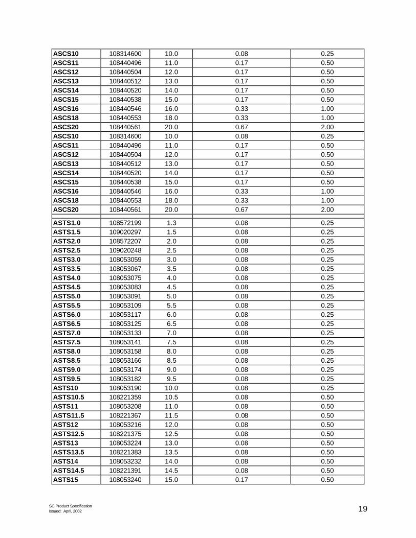
3.8 – ASCS Series Modular Attenuator “Caps” Attenuation Levels and Performance
All numbers apply for 1550 nm and 0 dBm signals (These attenuator Caps are Green)
PRODUCT CODE
ORDER COMCODE
NOMINAL LOSS (dB)
TYPICAL STANDARD DEVIATION IN LOSS
(dB)
NOMINAL LOSS TOLERANCE
+/- (dB)
ASCS1.0 108538760 1.3 0.08 0.25 ASCS1.5 109020271 1.5 0.08 0.25 ASCS2.0 108538778 2.0 0.08 0.25 ASCS2.5 109020214 2.5 0.08 0.25 ASCS3.0 108314469 3.0 0.08 0.25 ASCS3.5 108314477 3.5 0.08 0.25 ASCS4.0 108314485 4.0 0.08 0.25 ASCS4.5 108314493 4.5 0.08 0.25 ASCS5.0 108314501 5.0 0.08 0.25 ASCS5.5 108314519 5.5 0.08 0.25 ASCS6.0 108314527 6.0 0.08 0.25 ASCS6.5 108314535 6.5 0.08 0.25 ASCS7.0 108314543 7.0 0.08 0.25 ASCS7.5 108314550 7.5 0.08 0.25 ASCS8.0 108314568 8.0 0.08 0.25 ASCS8.5 108314576 8.5 0.08 0.25 ASCS9.0 108314584 9.0 0.08 0.25 ASCS9.5 108314592 9.5 0.08 0.25
SC Product Specification Issued: April, 2002 19
ASCS10 108314600 10.0 0.08 0.25 ASCS11 108440496 11.0 0.17 0.50 ASCS12 108440504 12.0 0.17 0.50 ASCS13 108440512 13.0 0.17 0.50 ASCS14 108440520 14.0 0.17 0.50 ASCS15 108440538 15.0 0.17 0.50 ASCS16 108440546 16.0 0.33 1.00 ASCS18 108440553 18.0 0.33 1.00 ASCS20 108440561 20.0 0.67 2.00 ASCS10 108314600 10.0 0.08 0.25 ASCS11 108440496 11.0 0.17 0.50 ASCS12 108440504 12.0 0.17 0.50 ASCS13 108440512 13.0 0.17 0.50 ASCS14 108440520 14.0 0.17 0.50 ASCS15 108440538 15.0 0.17 0.50 ASCS16 108440546 16.0 0.33 1.00 ASCS18 108440553 18.0 0.33 1.00 ASCS20 108440561 20.0 0.67 2.00 ASTS1.0 108572199 1.3 0.08 0.25 ASTS1.5 109020297 1.5 0.08 0.25 ASTS2.0 108572207 2.0 0.08 0.25 ASTS2.5 109020248 2.5 0.08 0.25 ASTS3.0 108053059 3.0 0.08 0.25 ASTS3.5 108053067 3.5 0.08 0.25 ASTS4.0 108053075 4.0 0.08 0.25 ASTS4.5 108053083 4.5 0.08 0.25 ASTS5.0 108053091 5.0 0.08 0.25 ASTS5.5 108053109 5.5 0.08 0.25 ASTS6.0 108053117 6.0 0.08 0.25 ASTS6.5 108053125 6.5 0.08 0.25 ASTS7.0 108053133 7.0 0.08 0.25 ASTS7.5 108053141 7.5 0.08 0.25 ASTS8.0 108053158 8.0 0.08 0.25 ASTS8.5 108053166 8.5 0.08 0.25 ASTS9.0 108053174 9.0 0.08 0.25 ASTS9.5 108053182 9.5 0.08 0.25 ASTS10 108053190 10.0 0.08 0.25 ASTS10.5 108221359 10.5 0.08 0.50 ASTS11 108053208 11.0 0.08 0.50 ASTS11.5 108221367 11.5 0.08 0.50 ASTS12 108053216 12.0 0.08 0.50 ASTS12.5 108221375 12.5 0.08 0.50 ASTS13 108053224 13.0 0.08 0.50 ASTS13.5 108221383 13.5 0.08 0.50 ASTS14 108053232 14.0 0.08 0.50 ASTS14.5 108221391 14.5 0.08 0.50 ASTS15 108053240 15.0 0.17 0.50

SC Product Specification Issued: April, 2002 20
ASTS16 108053257 16.0 0.33 1.00 ASTS18 108053265 18.0 0.33 1.00 ASTS20 108053273 20.0 0.67 2.00 AFCS1.0 108385493 1.3 0.08 0.25 AFCS1.5 109020255 1.5 0.08 0.25 AFCS2.0 108385501 2.0 0.08 0.25 AFCS2.5 109020230 2.5 0.08 0.25 AFCS3.0 108107053 3.0 0.08 0.25 AFCS3.5 108107061 3.5 0.08 0.25 AFCS4.0 108107079 4.0 0.08 0.25 AFCS4.5 108107087 4.5 0.08 0.25 AFCS5.0 108107095 5.0 0.08 0.25 AFCS5.5 108107103 5.5 0.08 0.25 AFCS6.0 108107111 6.0 0.08 0.25 AFCS6.5 108107129 6.5 0.08 0.25 AFCS7.0 108107137 7.0 0.08 0.25 AFCS7.5 108107145 7.5 0.08 0.25 AFCS8.0 108107152 8.0 0.08 0.25 AFCS8.5 108107160 8.5 0.08 0.25 AFCS9.0 108107178 9.0 0.08 0.25 AFCS9.5 108107186 9.5 0.08 0.25 AFCS10 108107194 10.0 0.08 0.25 AFCS10.5 108229097 10.5 0.08 0.50 AFCS11 108107202 11.0 0.08 0.50 AFCS11.5 108229105 11.5 0.08 0.50 AFCS12 108107210 12.0 0.08 0.50 AFCS12.5 108229113 12.5 0.08 0.50 AFCS13 108107228 13.0 0.08 0.50 AFCS13.5 108229139 13.5 0.08 0.50 AFCS14 108107236 14.0 0.08 0.50 AFCS14.5 108229147 14.5 0.08 0.50 AFCS15 108107244 14.5 0.08 0.50 AFCS16 108107251 16.0 0.33 1.00 AFCS18 108107269 18.0 0.33 1.00 AFCS20 108107277 20.0 0.67 2.00
Maximum Reflectance is –30dB Fiber Type is Singlemode The caps are laser marked with the nominal attenuation (dB)

SC Product Specification Issued: April, 2002 21
3.9 – ASCM Series Modular Attenuator “Caps”
Attenuation Levels and Performance (These attenuator Caps are Beige/Gray)
PRODUCT CODE
ORDER COMCODE
NOMINAL LOSS (dB)
@ 1550 nm
NOMINAL LOSS TOLERANCE
+/- (dB) @ 1550 nm
NOMINAL LOSS TOLERANCE
+/- (dB) @ 1310 nm
ASCM5 108440579 5.0 1.00 1.00 ASCM7 108440587 7.0 1.00 1.00 ASCM10 108440595 10.0 1.50 1.50 ASCM12 108440603 12.0 1.80 1.80 ASCM15 108440611 15.0 2.25 2.25 ASCM17 108440629 17.0 2.50 2.50 ASCM20 108440637 20.0 3.00 3.00 ASTM5 108052960 5.0 1.00 1.00 ASTM7 108052986 7.0 1.00 1.00 ASTM10 108052994 10.0 1.50 1.50 ASTM12 108053000 12.0 1.80 1.80 ASTM15 108053018 15.0 2.25 2.25 ASTM17 108053034 17.0 2.50 2.50 ASTM20 108053042 20.0 3.00 3.00 AFCM5 108107285 5.0 1.00 1.00 AFCM7 108107293 7.0 1.00 1.00 AFCM10 108107301 10.0 1.50 1.50 AFCM12 108107319 12.0 1.80 1.80 AFCM15 108107327 15.0 2.25 2.25 AFCM17 108107335 17.0 2.50 2.50 AFCM20 108107343 20.0 3.00 3.00
Maximum Reflectance is –30dB Fiber Type is SM launch, MM receive. The caps are laser marked with the nominal attenuation (dB)

SC Product Specification Issued: April, 2002 22
3.10 – ASCLR Series Modular Attenuator “Caps”
Attenuation Levels and Performance (These attenuator Caps are Light Blue)
PRODUCT CODE
ORDER COMCODE
NOMINAL LOSS (dB)
@ 1550 nm
NOMINAL LOSS TOLERANCE
+/- (dB) @ 1550 nm
NOMINAL LOSS TOLERANCE
+/- (dB) @ 1310 nm
ASCLR2 108647181 2.0 0.5 0.5 ASCLR3 108647447 3.0 0.5 0.5 ASCLR4 108647454 4.0 0.5 0.7 ASCLR5 108647462 5.0 0.5 1.0 ASCLR7 108647470 7.0 0.5 1.1 ASCLR10 108647488 10.0 0.5 1.5 ASCLR15 108647496 15.0 0.75 2.3 ASCLR20 108647504 20.0 1.0 3.0
Maximum Reflectance is –45dB Fiber Type is Singlemode The caps are laser marked with the nominal attenuation (dB)
3.11 – A3060N1 Series Modular Attenuator “Caps” Attenuation Levels and Performance
(These attenuator Caps are Yellow) PRODUCT
CODE ORDER
COMCODE NOMINAL LOSS
(dB) @ 1550 nm
NOMINAL LOSS TOLERANCE
+/- (dB) @ 1550 nm
NOMINAL LOSS TOLERANCE
+/- (dB) @ 1310 nm
A3060A1 107380420 3.0 - 0.5 A3060B1 107406142 5.0 - 1.0 A3060D1 107406159 10.0 - 1.0 A3060F1 107406167 15.0 - 2.0 A3060H1 107406175 20.0 - 2.0 A3060X1 107107732 7.0 - 0.7 A3070A1 107380438 3.0 - 0.5 A3070B1 107406183 5.0 - 1.0 A3070D1 107406191 10.0 - 1.0 A3070F1 107406209 15.0 - 2.0 A3070H1 107406217 20.0 - 2.0 A3070X1 107107740 7.0 - 0.7 A3080A1 107380466 3.0 - 0.5 A3080B1 107406225 5.0 - 1.0 A3080D1 107406233 10.0 - 1.0 A3080F1 107406241 15.0 - 2.0 A3080H1 107406258 20.0 - 2.0 A3080X1 107107757 7.0 - 0.7
Maximum Reflectance is –34dB Fiber Type is Singlemode The caps are laser marked with the nominal attenuation (dB)

SC Product Specification Issued: April, 2002 23
3.12 – Modular Adapter Spectral Flatness
Attenuation increases at lower wavelengths. Attenuation for wavelengths other than 1550 nm is described by the following equations: For ? < 1550 nm LS = A (1 + 3.88x10⁻⁴ (1550-? )) For ? > 1550 nm LS = A (1 - 3.88x10⁻⁴ (? -1550)) LS = Predicted loss of a randomly selected attenuator in dB A = Nominal Attenuation value in dB at 1550 nm and 0 dBm ? = Wavelength in nm
3.13 – Modular Adapter Power Divergence
Below 10 dBm the attenuation is not affected by the power level. At 10dBm and above the loss depends on Power and Attenuation level and can be described by the following equation: L = A + 0.213 - 0.0143 P + 0.000806 P2 + 0.0826 A - 0.00439 A2 + 0.000279 A3 - 0.00823 AP + 0.000358 AP2 L = Predicted loss of a rendomly seleceted unit in dB A = Nominal Attenuation value of the unit P = Power in dBm This dependence is shown in the plot below.
POWER DEPENDENCE ABOVE 10 dBm
0
0.5
1
1.5
2
2.5
3
10 15 20 25
Power , dBm
Loss
Incr
emen
t (L
- A
), dB
0.5
5
10
15
20
Attenuation Level

SC Product Specification Issued: April, 2002 24
3.14 – Modular Adapter Compliance to GR-910 and GR-326
Compliance to Telcordia GR-910 Split adapter attenuators, when assembled with either the A3002 ST Base or A3003 SC base comply with all the requirements of Telcordia GR-910 except the maximum reflection is greater than –40 dB. Compliance to Telcordia GR-326 0 dB Caps assembled with the A3002 ST or A3003 SC base comply with the requirements of GR-326 except the transmission under side loads exceeds the maximum change in loss at 4.4 pounds.

SC Product Specification Issued: April, 2002 25
4.0 – SC Build-On Attenuators

SC Product Specification Issued: April, 2002 26
4.1 – Build-On Attenuator System Application
SC Jumper ConnectorSC Simplex Adapter
SC Build-On Attenuator
AllWave ADVANTAGETM attenuators can enhance networks where you need attenuation. OFS Fitel’s standard-polish attenuators have low reflection to meet stringent system requirements and are backward compatible with existing transmission equipment. These AllWave attenuators are designed to provide flat spectral loss across the full spectrum, which allows the attenuators to operate in the entire wavelength region from 1280 nm to 1625 nm. These attenuators can be placed either on the receive side of the LGX or directly on the active equipment. These “build-on” style attenuators are a combination of an SC connector on one end, and an SC adapter on the other end. This allows the attenuator to be placed in-line between an adapter and a jumper of pigtail. The AllWwave Attenuator achieves the desired attenuation by using a specific grade of high-loss fiber epoxied into a ferrule that is assembled into the attenuator. By using a fiber-ferrule technology, return loss measurements of 50* dB or better can be achieved. The end-face geometry of both the inside & outside ferrule surfaces meet the same requirements and specifications found in Sections 6.7 and 6.8 for Polished Ferrule End-Face Geometry. *Note: for APC, return loss is >60 dB
4.2 – Build-On Attenuator Footprint Illustration
0.360”
1.380”
0.500”

SC Product Specification Issued: April, 2002 27
4.3 – Build-On Attenuator Materials and Specifications
Connector Part Material UL 94 Rating Oxygen Index Attenuator Engineering Plastic ?? ?? Ferrule Ceramic - - Barrel Metal - -
Specifications: Units Value Physical SC “In-Line” Adapter Type Color Metallic silver Transmission Singlemode Nominal Attenuation @ 1550 nm and 0 dBm dB See Table for each type Attenuation Tolerance @ 1550 nm and 0 dBm dB See Table for each type Maximum Spectral Attenuation Variation (1300 to 1620 nm) dB ? Maximum Attenuation Variation Due to Incident Power dB ? Maximum Incident Optical Power Handling Capability dBm 25 (?) Reflectance dB See table for each type Operating Temperature °C -40 to 75 Matings over Life ??
4.4 – Build-On Attenuator Coding Scheme
A B SC S - 3.0 | | | | |
Attenuator Type Connector Type
Style Attenuation
B – Build-On SC – SC S – PC A – APC
This number represents the attenuation value.

SC Product Specification Issued: April, 2002 28
4.5 – ABSCS Series Build-on Attenuator
Attenuation Levels and Performance (PC polish) All numbers apply for 1550 nm and 0 dBm signals
PRODUCT CODE
ORDER COMCODE
NOMINAL LOSS (dB)
MINIMUM RETURN
LOSS (dB)
TYPICAL STANDARD DEVIATION
NOMINAL LOSS TOLERANCE
+/- (dB)
ABSCS-0.5 109177634 0.5 50 - 0.25 ABSCS-1.0 109177683 1.0 50 - 0.25 ABSCS-1.5 109177758 1.5 50 - 0.25 ABSCS-2.0 109177808 2.0 50 - 0.25 ABSCS-2.5 109177857 2.5 50 - 0.25 ABSCS-3.0 109177642 3.0 50 - 0.25 ABSCS-3.5 109177659 3.5 50 - 0.25 ABSCS-4.0 109177667 4.0 50 - 0.25 ABSCS-4.5 109177675 4.5 50 - 0.25 ABSCS-5.0 108617549 5.0 50 - 0.5 ABSCS-6.0 109177709 6.0 50 - 0.5 ABSCS-7.0 109177717 7.0 50 - 0.5 ABSCS-8.0 109177733 8.0 50 - 0.5 ABSCS-9.0 109177741 9.0 50 - 0.5 ABSCS-10.0 108617556 10.0 50 - 0.5 ABSCS-11.0 109177766 11.0 50 - 0.5 ABSCS-12.0 109177774 12.0 50 - 0.5 ABSCS-13.0 109177782 13.0 50 - 0.5 ABSCS-14.0 109177790 14.0 50 - 0.5 ABSCS-15.0 108618554 15.0 50 - 0.5 ABSCS-16.0 109177816 16.0 50 - 0.5 ABSCS-17.0 109177824 17.0 50 - 0.5 ABSCS-18.0 109177832 18.0 50 - 0.5 ABSCS-19.0 109177840 19.0 50 - 0.5 ABSCS-20.0 108618562 20.0 50 - 1.0 ABSCS-25.0 109177865 25.0 50 - 2.0
4.6 – ABSCA Series Build-on Attenuator Attenuation Levels and Performance (APC Polish)
All numbers apply for 1550 nm and 0 dBm signals PRODUCT
CODE ORDER
COMCODE NOMINAL
LOSS (dB)
MINIMUM RETURN
LOSS (dB)
TYPICAL STANDARD DEVIATION
NOMINAL LOSS TOLERANCE
+/- (dB) ABSCA-03.0 108618570 3.0 60 - 0.15 ABSCA-05.0 108618588 5.0 60 - 0.15 ABSCA-07.0 108618596 7.0 60 - 0.15 ABSCA-10.0 108618504 10.0 60 - 0.15 ABSCA-15.0 108618512 15.0 60 - 0.15

SC Product Specification Issued: April, 2002 29
ABSCA-20.0 108618520 20.0 60 - 0.15
5.0 – SC Terminator Specification

SC Product Specification Issued: April, 2002 30
5.1 – SC Terminator Application
Terminators are designed to reduce back-reflections typically found on laser-activated, connectorized access points such as those found on splitters, DWDM’s or Fiber Distribution Frames (LGXTM). With the rapid deployment of high-speed optical multiplexers, the possibility of having an unterminated derived channel or branch increases. Any single fiber connector mated to an adapter or coupling, that is unused, is a source of back-reflection. Back-reflection can be a major cause of bit errors within the system. Features: ?? Engineered Plastic ferrules ?? Available in SC, FC, LC and MU ?? Up to 20 re-matings ?? Operational between 1310 and 1550 nm ?? -45 dB reflectance Benefits: ?? Low cost ?? Compatible to most connector types ?? Effectively removes back-reflectance
5.2 – Terminator Information and Performance
PRODUCT CODE
ORDER COMCODE
DESCRIPTION REFLECTANCE
LC-T 108 904 368 LC Terminator <45 dB LC-T-100 108 897 356 LC Terminator (100 pack) <45 dB SC-T 107 796 864 SC Terminator <45 dB SC-T-100 107 860 157 SC Terminator (100 pack) <45 dB FC-T 107 857 104 FC Terminator <45 dB FC-T-100 108 897 380 FC Terminator (100 pack) <45 dB

SC Product Specification Issued: April, 2002 31
6.0 – SC-LC Converter

SC Product Specification Issued: April, 2002 32
6.1 – SC-LC Converter Application
The SC-to-LC Converter features an SC connector on the front and a LC adapter on the back. This converter can be used in those applications where customers may have chosen to convert to the LC system (connectors and jumpers) but still has an embedded base of SC adapters in their system. The converter has been designed to yield an insertion loss of =0.5 dB, and to prevent Multipath Interference (MPI).
6.2 – SC-LC Converter Footprint Illustration
6.3 – SC-LC Converter Information and Performance
PRODUCT
CODE
ORDER
COMCODE
DESCRIPTION
MAXIMUM INSERTION LOSS
(dB) 109 119 834 SC-LC Converter 0.5

SC Product Specification Issued: April, 2002 33
7.0 – SC Jumper Specification

SC Product Specification Issued: April, 2002 34
7.1 – SC Simplex Jumper
7.2 – SC Simplex Jumper Exploded Assembly
Narrow End of Cable Support
Cable Support
Metal End of Crimp Sleeve
Heat Shrink TubingCrimp Sleeve Sub-assembly

SC Product Specification Issued: April, 2002 35
7.3 – SC Duplex Jumper Exploded Assembly
Duplex Clip
Cable supports
Crimp sleeve (yellow)
Blue buffer B channel opening
B channel opening
A channel opening
A channel opening
Crimp sleeve (yellow)
Crimp sleeve (white) Cable supports
Blue buffer
Orange buffer
7.4 – SC Duplex MM Jumper as per TIA/EIA
End1 Channel B
End 2 Channel BEnd 1 Channel A
End 2 Channel AOrange Fiber
Blue Fiber

SC Product Specification Issued: April, 2002 36
7.5 – SC Jumper/Connector Materials
Connector Part Material UL 94 Rating Oxygen Index Ferrule Zirconia - - Barrel Stainless Steel - - Cable Support Boot Engineering Plastics V-0 29 Spring Stainless Steel - - Plug Frame Engineering Plastics V-0 34 Duplex Clip Engineering Plastics V-0 35 Grip Engineering Plastics V-0 34 Buffer Boot Engineering Plastics V-0 29 Cable Retention Member Ni-plated Brass - - Crimp Sleeve Anodized Aluminum - - Sheath Tube Ni-plated Brass - - 1.6mm Minicord UL 1666 Jacket PVC Buffer Nylon Strength Material Aramid Yarn
7.6 – Cordage Technical Specifications
Multimode Fiber, Core/Cladding 62.5/125 microns Singlemode Fiber, Core/Cladding 8.3/125 microns Fiber Coating 250 micron Buffer Diameter 0.9 mm Jacket Diameter, Minicord
Standard Cordage 1.6 mm 3.0 mm
Fiber Proof Test 100 KPSIs (689 N/mm2) Cordage Proof Test, Minicord
Standard Cordage 20 lb. (89 N) 30 lb. (133 N)

SC Product Specification Issued: April, 2002 37
7.7 – SC Singlemode Ferrule Endface Geometry
Item Reference Minimum Nominal Maximum Dimensions Radius A 10 25 mm
Pedestal? B 1.75 1.9 2.26 mm Dome ECC. — 0 — 0.050 mm
Chamfer C 25 30 35 degrees Undercut D — — See Graph A nm
Protrusion E — — 50 nm *Pedestal diameter after polishing.
Note: Dimensions in table below are for reference only and apply after polishing procedures have been completed.
Acceptable values under the curve
Graph A. Recommended Fiber Undercut
Note: End-face geometry is reference information only (non-critical inspection points). Return Loss and insertion loss are the critical inspection criteria.

SC Product Specification Issued: April, 2002 38
7.8 – SC APC Ferrule End-face Geometry
D
EFIBER END-FACE
8?
B
A
SECTION
END VIEWC
Item Reference Minimum Nominal Maximum Dimensions Radius A 5 - 12 mm
Pedestal B 0.8 - 1.7 mm Dome ECC. - 0 - 0.050 mm
Chamfer C 25 - 35 degrees Undercut D - - 100 nm
Protrusion E - - 100 nm
Note: End-face geometry is reference information only (non-critical inspection points). Return Loss and insertion loss are the critical inspection criteria.

SC Product Specification Issued: April, 2002 39
7.9 – SC APC Ferrule/Angle Orientation
8?
TOP VIEW
Connector Key
7.10 – SC Factory Made PC Patch Cord – Specifications
Fiber Type Singlemode PC APC Multimode Loss1: Avg./Std. Dev. 0.15 dB/0.08 dB (Tuned)* 0.25 dB/0.12 dB 0.2 dB/0.1 dB Loss1: Maximum 0.3 dB3 0.5 dB 0.5 Return Loss Minimum 55 dB 65 dB 20 dB Cable Retention2 (1.6mm) (3.0 mm)
20 lbs./29.67 N 30 lbs./44.5 N
20 lbs./89 N 30 lbs./133 N
20 lbs./89 N 30 lbs./133 N
Mating Durability (500 Reconnects) Insertion Loss Change
< 0.2 dB
< 0.2 dB
< 0.2 dB
Temp. Stability (-40 ?C to 75 ?C) Insertion Loss Change
< 0.3 dB
< 0.3 dB
< 0.3 dB
1. Complete connection concatenated statistics 8.8/125 fiber, 62.5/125 fiber. Dry connection. 2. Values represent axial force on connector with 0? axial pull on cordage. See cordage specification in
Section 7.6. Cable dependent to cause permanent light transmission failure. Figures representative of use with OFS Fitel jumper cordage or equivalent.
3. The performance is representative of all SC-PC factory patchcords herein. Xmax + 2? = 0.31 dB, Xmax + 3? = 0.39 dB
4. Optical performance is dependant on ferrule endface cleanliness. Cleaning the endface prior to examination or installation is recommended. See Telcordia GR-326_COR, Issue 3, September 1999, Section 4.3 for recommended cleaning procedure.

SC Product Specification Issued: April, 2002 40
FERRULE
7.11 – Visual Inspection Criteria for Fiber Optic Connectors with Fiber
INSPECTION CRITERIA: SINGLEMODE
A Core Zone
Diameter 0 - 25 µm Scratches (SM) None Pits & Chips None Contamination None Crack None Other
B Cladding Zone
Diameter 25 - 120 µm Scratches (SM) Up to 3 scratches of any
length, 1-3 ? m width Pits & Chips Unlimited (<2 ? m dia.) Contamination None Crack None
C Epoxy Zone
Diameter 120 - 130 µm Scratches (SM) Unlimited Pits & Chips Unlimited (<5 µm dia.) Contamination No loose particles
D Contact Zone
Diameter 130 - 250 µm Scratches (SM) Unlimited Pits & Chips Unlimited Contamination No loose particles
INSPECTION CRITERIA: SINGLEMODE_APC same as singlemode above except as noted.
A Core Zone
Scratches Any length, ? 2 ? m width if optical requirements are met
B Cladding Zone
Scratches Any length, ? 2 ? m width
INSPECTION CRITERIA: MULTIMODE same as singlemode above except as noted.
A Core Zone
Diameter 0 - 62 µm
Scratches Any length, ? 2 ? m width if optical requirements are met
B Cladding Zone
Diameter 62 - 120 µm
Scratches Any length, ? 2 ? m width
Magnification (minimum)
Resolving Power
Numerical Aperture
200x
1 µm
0.3
Notes: 1. For optical performance, see Table 5.10 of Factory
Made PC Patch Cord - Specification. 2. Proposed measurement method IEC 86B WG4 61300
3-X dated October 2001. 3. Since loose particles may be introduced during the
inspection process, cleaning the end-face is recommended prior to insertion into the microscope. Cleaning procedures are found in Section 4.3 of Telcordia GR-326-CORE, Issue 3, September 1999.
4. Figure and singlemode Table proposed IEC 86B WG6 Level 2 Specification for polished fiber end faces. Scratches and defects ?1.0 µm are not counted. Dated October 2001, except 2 ?m scratch width & pit diameter was 1 ?m.
5. Outside the 250 ?m contact zone there are no requirements for visual inspection since defects found in this region have no influence on the optical performance of PC polished ferrules.
Figure not-to-scale.
C B
D
A
FIBER

SC Product Specification Issued: April, 2002 41
7.12 – SC SM Jumper Tuning Configuration
? /2
?
Key Position
Ferrule
Barrel Fiber Core
Notes: If tuning is required to minimize loss, the eccentricity of the fiber core is to be located relative to the connector key within the angle ? as shown. ? ? 180?

SC Product Specification Issued: April, 2002 42
7.13 – SC Jumpers – Available Configurations
SC-SC Duplex Jumper on 1.6 mm Cordage Shown
Length Per Code6” Min. to 12” Max.
154.2mm to 226.6mm
SC-SC SC-LC SC-FC SC-ST SM & MM SM & MM SM & MM SM & MM
Simplex & Duplex Simplex & Duplex Simplex & Duplex Simplex & Duplex
Feet Available Lengths and Tolerances Meters 4 +0.5/-0 1.2 +0.15/-0 5 +0.5/-0 1.5 +0.15/-0 6 +0.5/-0 1.8 +0.15/-0 8 +0.5/-0 2.4 +0.15/-0
10 +0.5/-0 3.1 +0.15/-0 15 +1/-0 4.6 +0.3/-0 20 +1/-0 6.1 +0.3/-0 25 +1/-0 7.6 +0.3/-0 30 +1/-0 9.2 +0.3/-0 35 +1/-0 10.7 +0.3/-0 40 +1/-0 12.2 +0.3/-0 50 +1/-0 15.2 +0.3/-0 75 +1/-0 22.9 +0.3/-0
100 +1/-0 30.5 +0.3/-0

SC Product Specification Issued: April, 2002 43
7.14 – SC Jumper Coding Scheme
M S 2 SC - SC - 10 | | | | |
Cordage Type
Fiber Type Jumper Type
Connector Type (end 1)
Connector Type (end 2)
Length (ft)
M - Minicord S - SM 1-Simplex SC for SC SC for SC B - SBJ L - MM (62.5) 2-Duplex SCA for SC Angled
W - AllWaveTM 4-Quad SCA for SC Angled
FC for FC N - Nylon Buffer D - LaserWaveTM FCA for FC Angled
SR – Red Jacket D4 for D4 F or L – 3.0mm SB – Blue Tiger EP for STII+ LC for LC LCA for LC Angled
7.15 – SC Jumper Color Coding
Jumper Connector Color Cordage Color SM Blue w/ White Boot Yellow
SM AllWave Blue w /White Boot Violet MM 62.5 ?m Beige w/ White Boot Slate (Gray)
MM LaserWave Beige w/ White Boot Aqua APC Green w/ Green Boot Yellow

SC Product Specification Issued: April, 2002 44
8.0 – SC Tools, Kits, and Consumables

SC Product Specification Issued: April, 2002 45
8.1 – Ordering Information
PRODUCT
CODE ORDER
COMCODE DESCRIPTION
1032J 108 313 685 SC Tool Kit 1032B5 106 705 213 Tool Kit with Oven for Epoxy 1032B6 106 919 012 Tool Kit with International Oven for Epoxy 1032F1 107 149 320 Tool Kit for EZ method D-182738 106 919 236 Consumables for mounting 100 MM connectors using epoxy D-182739 106 919 244 Consumables for mounting 100 SM connectors using epoxy D-182919 106 983 041 Crimp Sleeves for mounting 100 connectors on MiniCord Cable D-182804 107 148 942 Consumables for mounting 100 MM connectors using EZ D-182720 107 834 039 Consumables for mounting 100 SM connectors using EZ 1510A 108 237 710 Polishing Fixture 1510B 106 918 998 Crimping Tool 1510C 109 919 004 Curing Fixture 2A1 106 917 263 SC Duplex Connector Clip (bulk pack of 5)