iss water recovery system, vapor compression distillation
TRANSCRIPT
ISS Water Recovery System, Vapor Compression Distillation
Process in Microgravity Date: October 16, 2019
Layne CarterISS Water Subsystem ManagerNASA/MSFC/ES62
Greg SchunkThermal Analysis and Control BranchNASA/MSFC/EV34

Outline
2
• Microgravity Considerations
• Water Recovery System Architecture
• UPA Overview
• Partial Gravity Urine Recovery
• Fluid Physics Challenges

Introduction
3
• Water treatment processes in microgravity are challenged with multi-phase fluid flow
• Gas/liquid fluid flow occurs during waste water collection (urine, condensate, Sabatier product water) and during the treatment process as required (urine distillation, catalytic oxidation with gaseous oxygen)
• Gas/liquid fluid flow has typically not been an issue on ISS due to appropriate design solutions – Rotary or passive separators– Potentially higher pressure drop in microgravity will be evaluated with the GRC
Packed Bed Reactor Experiment (PBRE)• Solids in the liquid phase have also not been an issue as long as the system is
properly designed (i.e., filtration)• Primary issue with fluid physics has been with unexpected multi-phase flow
– Solids (e.g., precipitation, biomass, catalyst fines) in the absence of gravity will tend to fail systems
– Free gas will also impact system function if not properly managed (by occluding filters or adsorbent/IX media, or lodging in tanks)
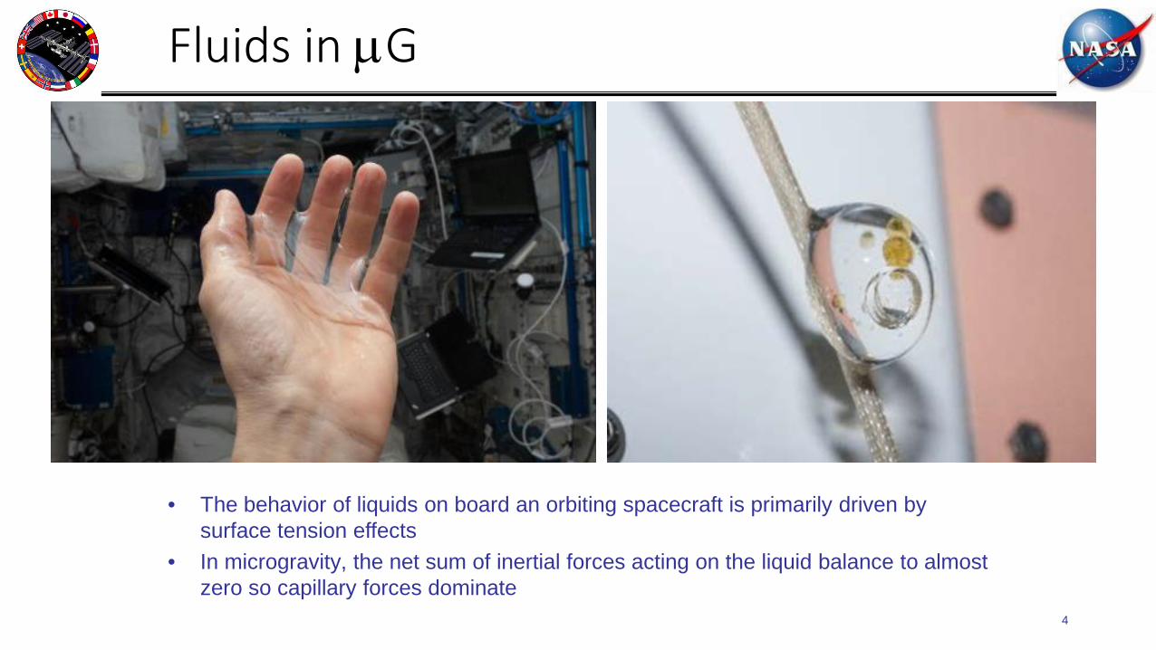
Fluids in µG
4
• The behavior of liquids on board an orbiting spacecraft is primarily driven by surface tension effects
• In microgravity, the net sum of inertial forces acting on the liquid balance to almost zero so capillary forces dominate

Fluids In µG
5

WRS & OGS Architecture Overview
WATER PROCESSOR ASSEMBLY (WPA)
DistillateCrew latent
Potable waterPotable water
Oxygen
USOS CABIN
CREW - drinking- hygiene- urine flush
BIOLOGICAL PAYLOADS
URINE PROCESSORASSEMBLY (UPA)
OXYGEN GENERATORASSEMBLY (OGA)
• Solid PolymerElectrolysis (SPE)
Water Recovery System (WRS)
CO2 REDUCTIONSYSTEM (CRS)
Pretreated Urine
• Sabatier Reactor
Carbon Dioxide
Hydrogen
Oxygen Generation System (OGS)
Water
overboard
• Rotary Gas Separator• Particulate Filter• Multifiltration Beds• Catalytic Oxidation Reactor
Vapor CompressionDistillation (VCD)
BRINE PROCESSORASSEMBLY
(BPA)
BrineWater vaporUrinal
CHX
PWD

Common Cabin Air Assembly (CCAA)
WPA Waste Tank

Waste and Hygiene Compartment
8

ISS Waste & Hygiene Compartment
9

10
ISS Waste & Hygiene Compartment
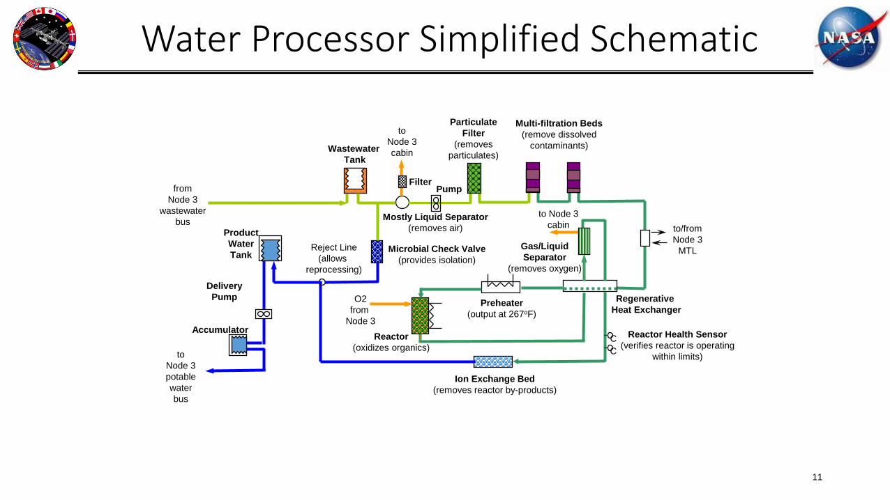
Water Processor Simplified Schematic
11
Ion Exchange Bed(removes reactor by-products)
Reactor(oxidizes organics)
Preheater(output at 267oF)
Regenerative Heat Exchanger
Gas/LiquidSeparator
(removes oxygen)
ParticulateFilter
(removesparticulates)
Multi-filtration Beds(remove dissolved
contaminants)
Mostly Liquid Separator(removes air)
FilterPump
Wastewater Tank
ProductWaterTank
DeliveryPump
Accumulator
O2from
Node 3
to Node 3cabin
toNode 3cabin
fromNode 3
wastewaterbus
toNode 3potablewaterbus
to/fromNode 3
MTLReject Line(allows
reprocessing)
Microbial Check Valve(provides isolation)
CC
Reactor Health Sensor(verifies reactor is operating
within limits)

Urine Processor Assembly Simplified Schematic
12
Urinefrom WHC
Wastewater Tank
Fluids Pump(FCPA)
Purge Pump(PCPA)
(removes non-condensable gases
from DA)
Coolant Interface(promotes condensation
within purge pump)
Purge Gasto Node 3 cabin
Product water to Water Processor Assembly
AdvancedRecycle Filter Tank Assembly
(ARFTA)(accumulates &
stores brine for disposal)
Separator(separates water from purge gases)
Brine Filter(removes
precipitates)
Distillation Assembly (DA)
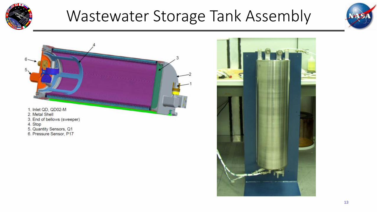
Wastewater Storage Tank Assembly
13

Advanced Recycle Filter Tank
14

Urine Processor Assembly Overview
• A vapor compression cycle is utilized to distill product water from pretreated urine. A pretreatment formulation is used to stabilize the urine after collection.
• The pretreated urine is concentrated to 75-85% recovery with the resulting brine returned to Earth.
• The process is very energy efficient as the heat of vaporization required for boiling of the pretreated urine at reduced pressure is provided by the condensed product water.
• The UPA is housed inside ISS WRS Rack #2 and is composed of the following components:
– Distillation Assembly (DA)– Fluids Control & Pump Assembly (FCPA)– Pressure Control & Pump Assembly (PCPA)– Firmware Controller Assembly (FCA)– Wastewater Storage Tank Assembly (WSTA)– Recycle Filter Tank Assembly (RFTA)– Separator Plumbing Assembly (SPA)

Distillation Assembly
Fluids Control & Pump Assembly
Recycle FilterTank Assembly
Wastewater StorageTank Assembly
Pre-treated urine from Node 3
To WPA WasteWater Tank
Flow Rate = 300 cc/min
Pressure Control & Pump AssemblySteam
Flow Rate = 4 lbs/hr
Separator Plumbing Assembly
Purge Gas
Waste WaterGasWater/FluidRecycle WaterProduct Water
Urine Processor Assembly OverviewMajor ORU’s and Process Flow

Urine Processor Assembly OverviewDistillation Assembly Cut-away

Urine Processor Assembly OverviewDistillation Assembly Cross Section
Feed Tube
Brine PickupTube
Demister
Evaporator Condenser
StationaryBowl
Centrifuge
Distillation PickupTube
Circumferential gap between the Condenser and Stationary Bowl located near the compressor outlet

Urine Processor Assembly OverviewInside the Distillation Assembly

Evaporator
Condenser
Superheated Steam@150oF
Stationary BowlProduct H2O@97oF
Urine/Pretreat Return@85oF
UrinePretreat Supply
Rotary LobeCompressor Motor
External Heaters prevent condensation in stationary bowl volume
Condenser
Stationary Bowl
Centrifuge rotates at 220 rpm
to achieve positive phase separation
Centrifuge
Pretreated urine boils at ~32mmHg pressure
Condensing steam surrenders latent heat of condensation
Water Vapor@85oF
Urine Processor Assembly OverviewDistillation Assembly Operation
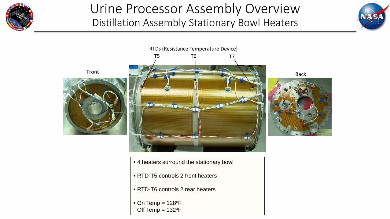
Urine Processor Assembly OverviewDistillation Assembly Stationary Bowl Heaters
T5 T7T6
Front Back
RTDs (Resistance Temperature Device)
• 4 heaters surround the stationary bowl
• RTD-T5 controls 2 front heaters
• RTD-T6 controls 2 rear heaters
• On Temp = 128ºFOff Temp = 132ºF

Fluid InFluid Out
Fluid In
Retaining Drum
CompressiveDrum
Fluid Out
Urine Processor Assembly OverviewInside the Pressure Control Pump Assembly

Coolant Flow In
• ISS MTL Coolant flows through a jacket in the PCPA enclosure– Allows for additional condensation of the water vapor, which increases the pumping
efficiency of the PCPA
4 Tubes
Inner Wall
Coolant Flow
Outer Wall
Urine Processor Assembly OverviewPressure Control Pump Assembly Cooling Jacket

Partial G Urine Recovery for Lunar/Planetary SurfaceNotional Concept
Waste Tank
Boiler
Condenser
Product Tank
Compressor
VacuumPump/Source
• A notional vapor compression distillation concept for lunar or planetary surface operation is presented.
• Pretreated urine is introduced into the boiler volume via gravity and the pressurized feed of the waste tank.
• As the urine is distilled, phase separation occurs naturally under the influence of gravity and steam is drawn of the boiler where it is compressed and introduced into the condenser.
• Operating at a ∆T of 10-15 oF, the heat of vaporization is recovered from the steam to boil the pretreated urine.
• Liquid condensate collected in the bottom of the condenser is gravity fed into a collection tank.
• A vacuum pump or source is needed to periodically draw non-condensable gases out of the condenser volume.
• A contingency heater is added if needed to drive off the last bit of water at very high solids concentrations.

Partial G Urine Recovery for Lunar/Planetary SurfaceFluid Physics Challenges
• Concentrated urine near solubility limits results in an elevated boiling point. Vapor compression alone may not be sufficient to drive the recovery of water beyond 95%.
• Higher operating temperatures result in lower ammonia solubility in water and perhaps increased evolution of ammonia gas.
• The process for solids separation after nearly 100% water recovery is TBD.• A mild concern exists over a lack of knowledge about the physics of boiling urine
under partial gravity conditions.• Operating in a gravitational field may provide design opportunities for buoyancy
driven movement of waste or product streams.

Urine Processor Assembly Fluid Physics Challenges for Exploration
• Downsizing the next generation UPA for exploration missions in microgravity environments (i.e. Mars Transit, Gateway, etc.) is a priority.
• Current UPA runs on a 25% duty cycle to meet ISS needs.
• Changes to the DA diameter or rotational speed may have unexpected consequences relative to boiling or condensation. Only changes in centrifuge length have been considered.
• DA condenser fluid physics is complex. Test correlated predictive modeling of boiling and condensation is needed to optimize the next generation UPA.
• Elimination of stationary bowl heaters may provide substantial benefit.
• Current system is energy efficient with a COP of approximately 4.0 (based on the latent energy of the product stream) but stationary bowl heaters consume 40-50% of the total process power.
2” lengthreduction
3.75” lengthreduction
Velocity Vectors

Backup

Overview
28
Average Human Metabolic Balance (lb/person-day)
Oxygen 1.84
Drinking Water 3.56
Water in Food 2.54
Food Prep Water 1.67
Food Solids 1.36
2.20 Carbon Dioxide
3.31 Urine
5.02 Perspiration/Respiration
0.20 H2O in Feces
0.24 Solids
Total 10.97 10.97 Total