ispm spacecraft antennas - open...
TRANSCRIPT

ISPM SPACECRAFT ANTENNAS
Item Type text; Proceedings
Authors Wong, Gary G.
Publisher International Foundation for Telemetering
Journal International Telemetering Conference Proceedings
Rights Copyright © International Foundation for Telemetering
Download date 13/05/2018 11:45:50
Link to Item http://hdl.handle.net/10150/613828

* This work was performed for the Jet Propulsion Laboratory, California Institute of Technology,sponsored by the National Aeronautic and Space Administration under Contract NAS7-1C0.
ISPM SPACECRAFT ANTENNAS*
Gary G. WongTRW Defense and Space Systems Group
One Space ParkRedondo Beach, CA 90278
ABSTRACT
International Solar Polar Mission (ISPM) is a dual-spacecraft mission sponsored jointly byNASA and European Space Agency (ESA) to gather scientific information for furtherunderstanding of the sun and predicting its influence on the Earth’s weather and climate.Jet Propulsion Laboratory of the California Institute of Technology has selected TRW tobuiId U.S. spacecraft for the joint mission. The dual spacecraft will fly to Jupiter and usethat planet’s greater gravitational field to achieve a near 90 degree orbit change, placingthe two spacecraft on separate trajectories to the North and South poles of the Sun from ahigh heliographic vantage point.
The antenna subsystem of the ISPM spacecraft consists of S-/X band high gain, S-bandbroad coverage, and X-Band medium gain antenna.
Command and ranging signals are received by the S-band high-gain and broad-coverageantennas. Scientific and engineering data are transmitted by these two antennas and theX-band high-gain antenna. Conscan acquisition is by the two S-band antennas. Emergencytransmissions are by the S-band broad coverage and X-band medium-gain antennas.
The S-/X-band HGA is a 1.9 meter (78 inches) diameter dual reflector Cassegrain designwith a dichroic subreflector. The Cassegrain mode is excited by an efficient dual modeconical horn whose dimensions have been optimized to provide high-gain performance forX-Band. The S-band feed, located directly behind the frequency selective subreflector,illuminates the parabolic reflector as a focal point feed, laterally displaced by 2.29 cm(0.9 inch) to provide conscan signals with a 1 dB crossover level. The selectedconfiguration permits the use of a common antenna for both X- and S-band functions andutilizes previously developed TRW hardware. The selected design represents the largestnon-deployable antenna that could be accommodated by shuttle/IUS and spacecraftphysical interfaces. An x-ray XUV telescope (CXX) is located on the center of thespacecraf t which is despun about the spacecraft +Z axis. The ends of the coronograph

cast shadows onto the edge of the reflector up to 9.72 cm (3.83 inches) inside the reflector.The shadowing effects from the coronograph have been analyzed and subsequentlyverified by antenna range testing. The performance of each antenna is substantiated byanalyses and test data and pertinent design and analysis results are presented.
INTRODUCTION
The ISPM antennas are configured primarily to meet the overall mission objectives andlink performance requirements of the telecommunication system. The spacecraft antennasselected for ISPM, to a great extent, are hardware developed and qualified configuration.The S-/X-band functions are performed with a common high-gain antenna. The S-bandcoverage antenna is the Pioneer 10 and 11 corrugated horn, used as is. The X-bandmedium gain horn is an existing design adapted from the DSCS II. These antennas employexisting TRW hardware and designs. Required gain and coverage characteristic areprovided at low weight, volume, complexity, and risk. Test results are available indicatingthe selected antenna configuration provides the required link performance. All antennasmount rigidly to the spacecraft structure, are carefully aligned, and are located to theminimized pattern interference as shown in Figure 1. The S-band broad coverage antennaand the X-band medium-gain horn have unobstructed viewing angles of 90 and 60 degrees,respectively. The S-/X-band and high-gain antenna is offset to minimize the patternperturbation from CXX instrument. Figure 2 presents the requirements versus capabilitiesof the antenna subsystem.
This paper discusses the design, analysis and performance characteristics details of theindividual antennas.
S-BAND/X-RAND HIGH-GAIN ANTENNA
The dual-function primary antenna (Figure 3) is a Cassegrain design with a dichroicsubreflector. The Cassegrain mode is excited by an X-Band dual mode conical horn. TheS-band feed, located directly behind the frequency selective subreflector, illuminates theparabolic reflector as a focal point feed, laterally displaced by a 2.29 cm (0.9 inch) toprovide conscan signals with a 1-dB crossover level. The selected configuration permitsthe use of a common antenna for both S- and X-band functions and utilizes previouslydeveloped TRW hardware.
The size of the main parabolic reflector, i.e., diameter (1.98 net) and focal length todiameter (f/D) ratio (.4), was dictated by mechanical envelope considerations. Electricaldesign efforts, are, therefore, restricted to the Cassegrain feed (primary feed horn anddichroic subreflector) geometry and feed components.

CASSEGRAIN FEED GEOMETRY
The geometry of the Cassegrain feed is shown in Figure 3C. Pertinent designcharacteristics are summarized in Figure 3B. A dual mode horn design was selected for theprimary feed. It offers high illumination efficiency over the operating frequency togetherwith design maturity. The Cassegrain geometry maximizes the performance of the antennafor S- and X-band. The selected design is similar to that used on LANDSAT-D.
The 31.90 cm (12.56 inch) diameter subreflector provides an optimum size from thestandpoint of blockage and diffraction (main reflector spillover) losses. The extension ofthe subreflector beyond the angle subtended by the main reflector minimizes the diffractionlosses caused by the electrically small subreflector.
X-BAND ANTENNA FEED
The antenna feed assembly (Figure 4A) is composed of three functional components:
• Primary feed horn - provides a circular symmetric right- hand circular polarized(RHCP) beam for efficient illumination of the subreflector.
• Circular polarizer - provides a 90 degree differential phase-shift to two linearorthogonally polarized signals.
• Mode transition - launches a TE11 circular waveguide mode from a dominantTE10 rectangular waveguide mode.
The dual mode conical horn operates over a relatively narrow frequency band, ascompared to a corrugated horn. A step in the horn’s throat causes a portion of the TE11
mode to be converted to the TM11 mode. By proper adjustment of relative power andphasing in each mode, a radiation pattern, with essentially no sidelobes and equal E and Hplanes beamwidths, are obtained at the operation frequency.
The dual mode conical horn geometry is shown in Figure 4A. The aperture is selected toprovide a 10-dB taper excitation to the subreflector.
Right-hand circular polarization is obtained by a circular waveguide iris-type polarizer.The polarizer consists of nine symmetrical irises formed inside the waveguide. The irisesare spaced a quarter of a guide wavelength apart and provide extremely small axial ratioover relatively wide bandwidths. Figures 4B through 4E show details of the polarizer andits performance in a feed.

Circular-to-rectangular guide taper transition provides the required interface between thepolarizer and the WR112 guide.
S-BAND FEED
A cavity-backed crossed dipole antenna fed through a quadrature hybrid provides theradiation pattern for illuminating the parabolic reflector. By proper choice of cavitydiameter and height, the optimum feed pattern is obtained for the particular f/D ratio of thereflector and secondary pattern desired. Figure 5A shows the S-band feed design details. Aquadrature hybrid permits either right- or left-hand circular polarization. The right-handcircularly polarized port is terminated into a matched load for the ISPM design.
DICHROIC SUBREFLECTOR
The dichroic subreflector consists of a hyperbolic surface that reflects the X-band feedradiation but is transparent to the S-band radiation. The selectivity is obtained by etchingmetallic crossed dipoles on a dielectric sheet that are resonant at X-band but very small interms of wavelength at S-Band. The angle of arrival of the X-band signal determines thebandwidth characteristics of the etched crossed dipoles. The dichroic subreflector dipoleand support structure dimensions are shown in Figures 6A and 6B.
The dichroic subreflector is 31.90 cm (12.56 inches) in diameter, providing an efficientscatter or diffraction pattern with negligible blockage. Figure 6 presents details of thisantenna. This unit (38.1 cm subreflector) consisted of Kevlar honeycomb facesheets ofwhich one facesheet, on the hyperbolic surface, contained the printed circuit dipoles.
Figure 6C presents the measured radiation patterns of a 9-foot diameter reflector at 14.0GHz. The worst case reflection loss is less than 0.1 dB, and the effect on the patternbeamwidth or sidelobes is negligible.
Similar tests were performed at S-band except that the radiation were recorded with andwithout the dichroic subreflector. Figure 6C presents the measured patterns at 2.1 and 2.3GHz. The worst case transmission loss was less than 0.2 dB, and the effect on the patternbeamwidth and sidelobes was negligible.
S-/X-BAND HIGH-GAIN ANTENNA PERFORMANCE
Pattern performance and antenna gain of the high-gain antenna were determined usingTRW proprietary computer programs. The computer programs account for all importantantenna parameters, including feed pattern spillover and efficiency, subreflector diffractionpattern, reflector edge diffraction, subreflector/feed blockage, and thermal distortion of the

feed, subreflector and reflector. Figure 7D presents the S-/X-band high-gain antennagain/loss budgets for the transmit and receive bands and determined by the programs.
The computer-calculated transmit radiation pattern of the antenna at X-band (8415 MHz)is presented in Figure 7A. The calculated offset patterns for S-band, using the actualmeasured feed data from the existing cupped crossed dipole antenna, are shown in Figures7B and 7C for the transmit and receive frquencies of 2295 and 2113.3 MHz The offsetdimension of 2.29 cm (0.9 inch) provides the desired conscan beam with a 1-dB crossoverlevel.
The S-band feed is composed of a cavity-backed crossed dipole. A matching balun excitesthe dipoles and a 90 degree hybrid permits either right- or left-hand circular polarization.
The X-band feed is composed of four components: a machined aluminum dual modeconical horn, an electroformed copper iris type circular polarizer, an electroformed coppercircular-to-rectangular transition, and a machined aluminum mounting bracket. Allcomponents are attached via waveguide flanges. The assembled feed is attached to themain reflector via screws.
S-BAND BROAD COVERAGE ANTENNA
The proposed antenna is an unmodified design from Pioneer 10 and 11. It is a corrugatedconical horn excited by unequal length crossed dipoles. The antenna is permanentlyaligned so that its electrical axis is an angle of approximately 8 degrees with respect to thespacecraft geometric axis (+z axis). This alignment provides a coarse conscan pattern asthe spacecraft rotates about its spin axis. Its crossover level gain at the spin axis isnominally 1 dB down from the beam peak.
The antenna is right hand circular polarized, and its broad beam characteristics provide aconscan range of 10 degrees. The antenna has been qualified to handle 8.3 watts over apressure range of 1 to 3 x 10⁻⁵ torr (a power handling test will be conducted to assure a6 dB power handling margin for ISPM). The peak gain of the antenna is 16.2 dBi at thetransmit frequency and 15.2 dBi at the receive frequency. Over the transmit and receiveband, the coverage gain is greater than 10 dBi over a conical half angle of 18 degreesabout the mechanical antenna axis. The antenna VSWR is less than 1.5:1. The axial ratiocharacteristics are 1.2 and 4.5 dB for the transmit and receive frequencies.
As shown in Figure 8A, the aperture outer diameter is 42.20 cm (16.613 inches). Theantenna cone angle is 61.4 degrees. The corrugation depth is 4.80 cm (1.89 inches). Theoverall length of the antenna including the transition mount to offset the antenna beam is35.56 cm (14.0 inches). The pattern performance is shown in Figures 9B and 8C.
The broad coverage antenna assembly is composed of three major components: the horn,the balun assembly, and the transition mount. The total assembly (less RF cables) weighs1.668 kg (3-7 pounds).
The horn is a spot-welded assembly utilizing aluminum details. The interior of the horn hasa series of aluminum conical vanes.
The balun assembly has a machined tublar aluminum outer conductor and a solid aluminuminner conductor. The four dipoles are also aluminum machinings and are attached to thetop of the balun by threads.
The transition mount is an aluminum weldment. It is shaped like a truncated cone andflanged at both ends. The flanges provide for mounting the horn to the spacecraft structure.The flanges are reinforced with small triangular gussets. This unit provides the angulardegree offset positioning required for the broad coverage antenna assembly.
X-BAND MEDIUM-GAIN ANTENNA
The X-band medium-gain antenna design is a corrugated conical horn excited by crosseddipoles (see Figure 9). This antenna provides a near optimum gain of 18 dBi with a lowVSWR and low axial ratio. Design details of the antenna are shown in Figure 10A.
The aperture diameter is 3.4 wavelengths and the horn length is approximately 3.7wavelengths, with five corrugations per wavelength. The flare angle of the horn is 49degrees. The horn diameter and flare angle were selected to provide an axially symmetricbeam of 20 degrees half power beamwidth. The grooves were designed to produce anantenna pattern of low sidelobes and backlobe.
The right-hand circular polarization is provided by the unequal length crossed dipole.When the dipole arms were adjusted to provide the necessary phase quadrature, acoverage axial ratio less than 1 dB over 3 percent operating frequency bandwidth wasobtained.
The X-band medium-gain antenna is composed of three major components: the horn, thedipole assembly, and the waveguide mount assembly. The total assembly weighs 0.33 kg(.073 pound).
The horn is a machined aluminum configuration, the flanged base of which is the mountingbase for the horn and attaches to waveguide mount assembly via screws. The dipoleassembly is an unequal cross dipole configuration. The dipoles are machined copper partsattached to a 0.141 coaxial cable.

CORONAGRAPH EFFECTS ANALYSIS
The coronagraph is located outside of the high-gain antenna feed illumination fields. Itseffects on the high-gain antenna can be assessed in terms of shadowing. The coronagraphis despun about the +Z axis. For coronagraph pointing angles 2 between 37 to 60 degrees,the ends of the coronagraph cast shadows onto the edge of the reflector up to 9.72 cm(3.83 inches) inside the reflector. Only the difference in the two shadows provides apseudo conscan signal. This difference area cuts through the edge of the reflector for anominal angle 2 = 59.1 degrees. This occurs when 2 (pointing angle) = 60 degrees.
The pseudo conscan signal, which was computed for the maximum conscan pointing errorof 0.5 degree, is 4.8 x 10⁻⁵ Eo. A comparison between this pseudo conscan signal and asignal corresponding to a conscan pointing resolution of 0.01 degree shows that theconscan error voltage is 0.27 Eo, which is 5600 times greater than the pseudo conscansignals. Based on these results, it is concluded that the shadowing effects from thecoronagraph on the high-gain antenna will not adversely affect the conscan pointingaccuracy.
The geometric relationship betwen the main reflector and conronagraph is shown in Figure10, where the coronagraph is symmetrical about the pivot point. The coronagraph length is101.60 cm (40 inches). the width is 15.24 cm (6 inches), and the height is 25.40 cm (10inches).
An experimental test was conducted using a mockup of the LANDSAT high-gain antenna(HGA) (see Figure 11). The purpose of the test was to obtain quick look data to assessSW1 and CXX interference effects on the ISPM HGA. The existing LANDSAT test setupwas used, and measurements were made at S- and Ku-band frequencies. Interferenceeffects were determined by recording signal fluctuations as the mockup was moved pastthe antenna reflector, thus dynamically testing the protrusion condition of SW1 and CXX.While the mockup was in fixed positions, the pattern and contour measurements were alsorecorded. Contour and pattern data were evaluated for beam squint behavior caused bySW1 and CXX interference. A summary of the test results is as follows:
1) At S- and Ku-band frequencies, the SW1 peak gain change is less than 0.14 dB.
2) At S- and Ku-band frequencies, the CXX peak gain change is less than 0.05 dB.
3) Contour data at Ku-band revealed no SW1 or CXX beam-squint.
4) Pattern measurement data revealed no S-band beam-squint.

5) Altering the separation distance between the obstruction (mockup) and thereflector produced no noticeable effect on signal disturbance.
6) Reducing the degree of intrusion to the reflector, however, resulted in apronounced reduction in signal variation.
FIGURE 1: ISPM SPACECRAFT
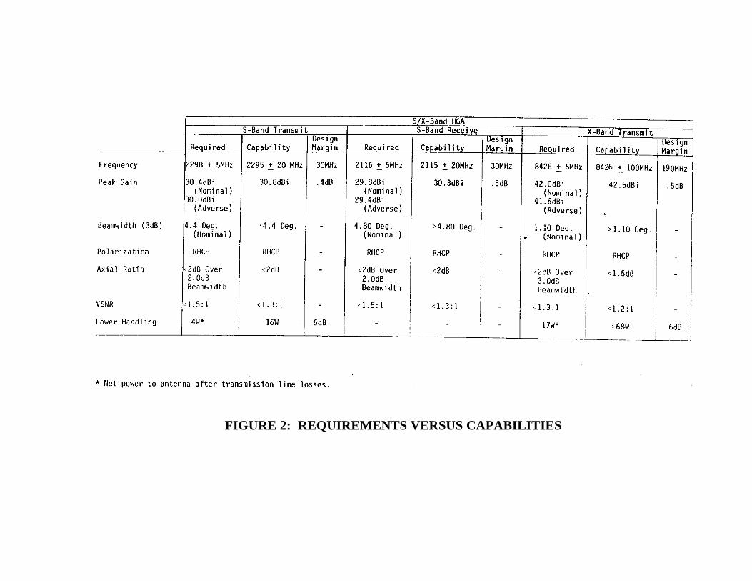
FIGURE 2: REQUIREMENTS VERSUS CAPABILITIES
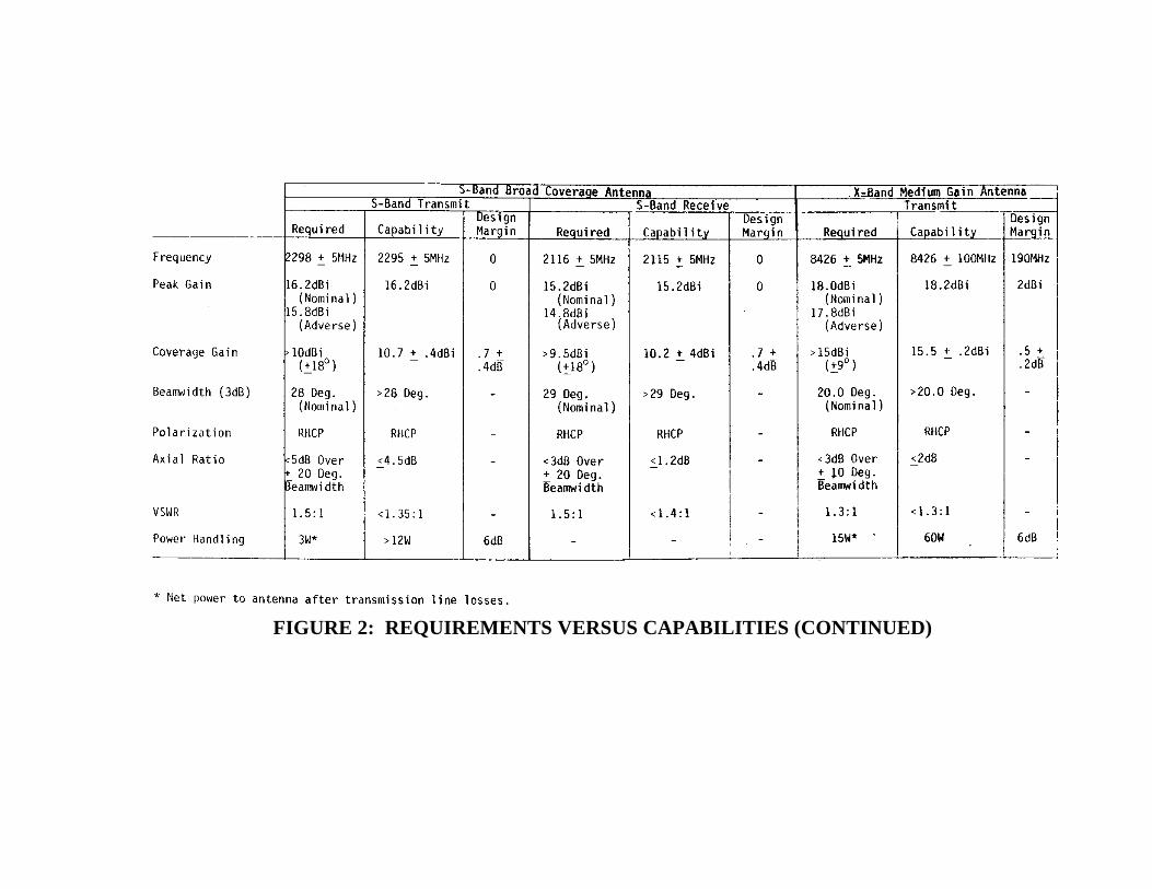
FIGURE 2: REQUIREMENTS VERSUS CAPABILITIES (CONTINUED)
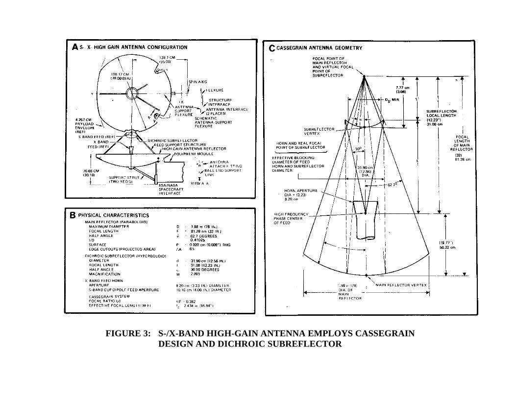
FIGURE 3: S-/X-BAND HIGH-GAIN ANTENNA EMPLOYS CASSEGRAINDESIGN AND DICHROIC SUBREFLECTOR

FIGURE 4: S-BAND HIGH-GAIN FEED USING A DUAL MODE HORN WITH IRIS POLARIZER
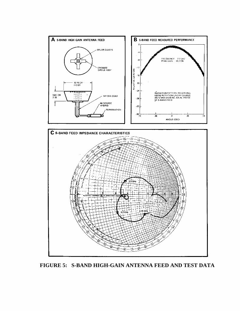
FIGURE 5: S-BAND HIGH-GAIN ANTENNA FEED AND TEST DATA
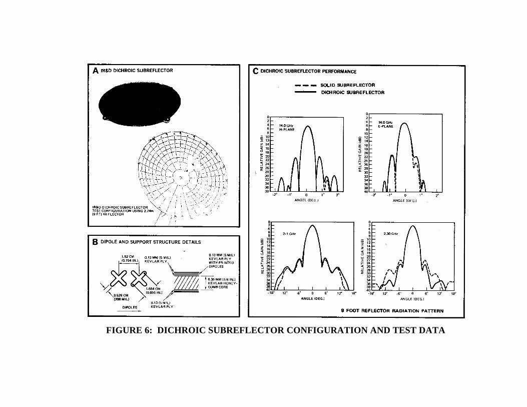
FIGURE 6: DICHROIC SUBREFLECTOR CONFIGURATION AND TEST DATA
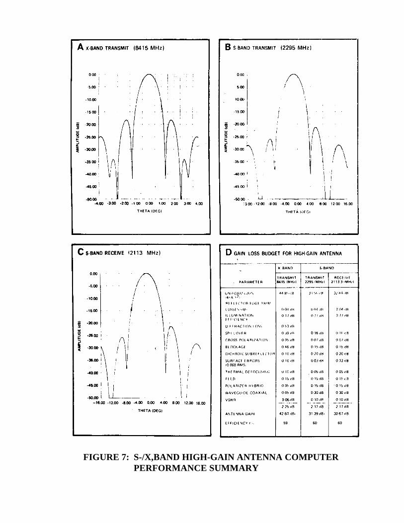
FIGURE 7: S-/X,BAND HIGH-GAIN ANTENNA COMPUTERPERFORMANCE SUMMARY

FIGURE 8: S-BAND BROAD COVERAGE ANTENNA IS THE PIONEER10 AND 11 DESIGN USED AS-IS

FIGURE 9: X-BAND MEDIUM-GAIN ANTENNA AND TEST RESULTS
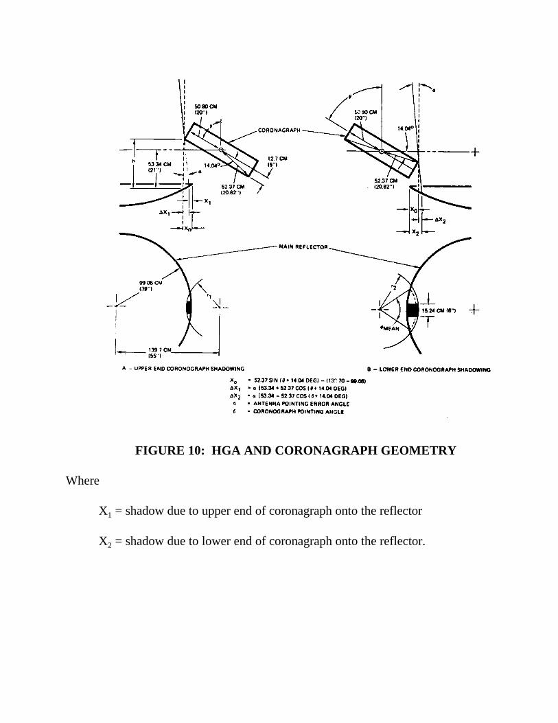
FIGURE 10: HGA AND CORONAGRAPH GEOMETRY
Where
X1 = shadow due to upper end of coronagraph onto the reflector
X2 = shadow due to lower end of coronagraph onto the reflector.
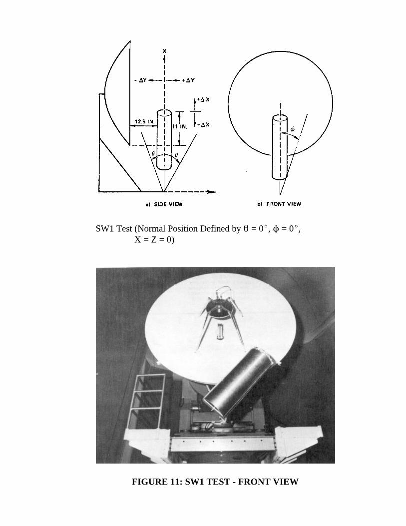
SW1 Test (Normal Position Defined by 2 = 0E, N = 0E,X = Z = 0)
FIGURE 11: SW1 TEST - FRONT VIEW