isoug425 d00220 xx m xxen - bender
TRANSCRIPT

EN Manual
Insulation monitoring device for earth fault detection in unearthedDC systems (IT systems) up to 120 V Software version: D0476 V2.xx
ISOMETER® isoUG425
isoUG425_D00220_03_M_XXEN/03.2021

Bender GmbH & Co. KGPO box 1161 • 35301 Grünberg • GermanyLondorfer Strasse 65 • 35305 Grünberg • Germany
Tel.: +49 6401 807-0Fax: +49 6401 807-259
E-Mail: [email protected]: www.bender.de
© Bender GmbH & Co. KGAll rights reserved.
Reprinting only with permissionof the publisher.
Subject to change!
Customer serviceService hotline: 0700-BenderHelp (Telephone and Fax)Carl-Benz-Strasse 8 • 35305 Grünberg • Germany
Tel.:+49 6401 807-760Fax:+49 6401 807-629
E-Mail:[email protected]

T
3 isoUG425_D00220_03_M_XXEN/03.2021
1
2
3
ry . . . . . . . . . . . . . . . . . . . . . . . . . . . . . . . . . . . . . . . . . . . . . . . . .10
ory HiS . . . . . . . . . . . . . . . . . . . . . . . . . . . . . . . . . . . . . . . . . . .10
rotocols . . . . . . . . . . . . . . . . . . . . . . . . . . . . . . . . . . . . . . . . . . .11
ction and commissioning ............................12
. . . . . . . . . . . . . . . . . . . . . . . . . . . . . . . . . . . . . . . . . . . . . . . . . . . .12
. . . . . . . . . . . . . . . . . . . . . . . . . . . . . . . . . . . . . . . . . . . . . . . . . . . .13
. . . . . . . . . . . . . . . . . . . . . . . . . . . . . . . . . . . . . . . . . . . . . . . . . . . .14
evice .................................................................15
s . . . . . . . . . . . . . . . . . . . . . . . . . . . . . . . . . . . . . . . . . . . . . . . . . .15
. . . . . . . . . . . . . . . . . . . . . . . . . . . . . . . . . . . . . . . . . . . . . . . . . . . .16
. . . . . . . . . . . . . . . . . . . . . . . . . . . . . . . . . . . . . . . . . . . . . . . . . . . .16
lue setting . . . . . . . . . . . . . . . . . . . . . . . . . . . . . . . . . . . . . . . .16
. . . . . . . . . . . . . . . . . . . . . . . . . . . . . . . . . . . . . . . . . . . . . . . . . . . .17
n of the relay operating mode . . . . . . . . . . . . . . . . . . . . .17
assignment "r1" and "r2" and LED assignment . . . . . .17
ry configuration . . . . . . . . . . . . . . . . . . . . . . . . . . . . . . . . . . .17
figuration . . . . . . . . . . . . . . . . . . . . . . . . . . . . . . . . . . . . . . . .17
. . . . . . . . . . . . . . . . . . . . . . . . . . . . . . . . . . . . . . . . . . . . . . . . . . . .18
uration . . . . . . . . . . . . . . . . . . . . . . . . . . . . . . . . . . . . . . . . . . . .18
. . . . . . . . . . . . . . . . . . . . . . . . . . . . . . . . . . . . . . . . . . . . . . . . . . . .18
nfiguration . . . . . . . . . . . . . . . . . . . . . . . . . . . . . . . . . . . . . . . .18
display and history memory. . . . . . . . . . . . . . . . . . . . . . . .18
he BMS protocol ...........................................19
able of Contents
. Important information .................................................................... 5
1.1 How to use this manual . . . . . . . . . . . . . . . . . . . . . . . . . . . . . . . . . . . . . . . . . . . . . 5
1.2 Technical support: Service and support . . . . . . . . . . . . . . . . . . . . . . . . . . . . . 5
1.2.1 First level support . . . . . . . . . . . . . . . . . . . . . . . . . . . . . . . . . . . . . . . . . . . . . . 5
1.2.2 Repair service . . . . . . . . . . . . . . . . . . . . . . . . . . . . . . . . . . . . . . . . . . . . . . . . . . 5
1.2.3 Field service . . . . . . . . . . . . . . . . . . . . . . . . . . . . . . . . . . . . . . . . . . . . . . . . . . . . 6
1.3 Training courses . . . . . . . . . . . . . . . . . . . . . . . . . . . . . . . . . . . . . . . . . . . . . . . . . . . . 6
1.4 Delivery conditions . . . . . . . . . . . . . . . . . . . . . . . . . . . . . . . . . . . . . . . . . . . . . . . . . 6
1.5 Inspection, transport and storage . . . . . . . . . . . . . . . . . . . . . . . . . . . . . . . . . . . 6
1.6 Warranty and liability . . . . . . . . . . . . . . . . . . . . . . . . . . . . . . . . . . . . . . . . . . . . . . . 6
1.7 Disposal. . . . . . . . . . . . . . . . . . . . . . . . . . . . . . . . . . . . . . . . . . . . . . . . . . . . . . . . . . . . 6
. Safety instructions ............................................................................ 7
2.1 General safety instructions . . . . . . . . . . . . . . . . . . . . . . . . . . . . . . . . . . . . . . . . . . 7
2.2 Work activities on electrical installations. . . . . . . . . . . . . . . . . . . . . . . . . . . . . 7
2.3 Intended use . . . . . . . . . . . . . . . . . . . . . . . . . . . . . . . . . . . . . . . . . . . . . . . . . . . . . . . 7
. Function ............................................................................................. 8
3.1 Device features . . . . . . . . . . . . . . . . . . . . . . . . . . . . . . . . . . . . . . . . . . . . . . . . . . . . . 8
3.2 Function description. . . . . . . . . . . . . . . . . . . . . . . . . . . . . . . . . . . . . . . . . . . . . . . . 8
3.2.1 Monitoring the insulation resistance . . . . . . . . . . . . . . . . . . . . . . . . . . . . 8
3.2.2 Undervoltage/overvoltage monitoring . . . . . . . . . . . . . . . . . . . . . . . . . . 8
3.2.3 Self test/error codes . . . . . . . . . . . . . . . . . . . . . . . . . . . . . . . . . . . . . . . . . . . . 8
3.2.4 Malfunction . . . . . . . . . . . . . . . . . . . . . . . . . . . . . . . . . . . . . . . . . . . . . . . . . . . . 9
3.2.5 Signalling assignment of the alarm relays K1/K2 . . . . . . . . . . . . . . . . . 9
3.2.6 Measuring and response times . . . . . . . . . . . . . . . . . . . . . . . . . . . . . . . . . 9
3.2.7 Password protection (on, OFF) . . . . . . . . . . . . . . . . . . . . . . . . . . . . . . . . . 10
3.2.8 Maximum permissible system leakage capacitance . . . . . . . . . . . . . 10
3.2.9 Factory setting FAC . . . . . . . . . . . . . . . . . . . . . . . . . . . . . . . . . . . . . . . . . . . 10
3.2.10 External, combined test or reset button T/R . . . . . . . . . . . . . . . . . . . . 10
3.2.11 Fault memo
3.2.12 History mem
3.2.13 Interface/p
4. Installation, conne
4.1 Mounting . . . . .
4.2 Wiring diagram
4.3 Commissioning
5. Operation of the d
5.1 Display element
5.2 Menu structure
5.3 "AL" menu . . . . .
5.3.1 Response va
5.4 "out" menu . . . .
5.4.1 Configuratio
5.4.2 Relay alarm
5.4.3 Fault memo
5.4.4 Interface con
5.5 "t" menu. . . . . . .
5.5.1 Time config
5.6 "SEt" menu . . . .
5.6.1 Function co
5.7 Measured value
6. Data access using t

isoUG425_D00220_03_M_XXEN/03.20214
7
8
9
1
10.1 Tabular representation . . . . . . . . . . . . . . . . . . . . . . . . . . . . . . . . . . . . . . . . . . . 28
10.2 Standards, approvals and certifications . . . . . . . . . . . . . . . . . . . . . . . . . . . 29
10.3 Ordering information. . . . . . . . . . . . . . . . . . . . . . . . . . . . . . . . . . . . . . . . . . . . . 29
10.4 Document revision history. . . . . . . . . . . . . . . . . . . . . . . . . . . . . . . . . . . . . . . . 30
INDEX .................................................................................................... 31
. Data access using the Modbus RTU protocol ............................ 20
7.1 Reading out the Modbus register from the ISOMETER®. . . . . . . . . . . . . . 20
7.1.1 Command of the master to the ISOMETER® . . . . . . . . . . . . . . . . . . . . . 20
7.1.2 The ISOMETER® answers the Master . . . . . . . . . . . . . . . . . . . . . . . . . . . . 20
7.2 Writing the Modbus register (parameter setting) . . . . . . . . . . . . . . . . . . . 20
7.2.1 Command of the Master to the ISOMETER® . . . . . . . . . . . . . . . . . . . . . 20
7.2.2 The ISOMETER® answers the Master . . . . . . . . . . . . . . . . . . . . . . . . . . . . 20
7.3 Exception code . . . . . . . . . . . . . . . . . . . . . . . . . . . . . . . . . . . . . . . . . . . . . . . . . . . . 21
7.3.1 Structure of the exception code . . . . . . . . . . . . . . . . . . . . . . . . . . . . . . . 21
. Modbus register assignment of the ISOMETER® ...................... 22
8.1 Device-specific data type of the ISOMETER® . . . . . . . . . . . . . . . . . . . . . . . . 24
8.1.1 Device name . . . . . . . . . . . . . . . . . . . . . . . . . . . . . . . . . . . . . . . . . . . . . . . . . . 24
8.1.2 Measured values . . . . . . . . . . . . . . . . . . . . . . . . . . . . . . . . . . . . . . . . . . . . . . 24
8.1.2.1 Float = Floating point value of the channels . . . . . . . . . . . . . . 24
8.1.2.2 AT&T = Alarm type and test type (internal/external) . . . . . . . 24
8.1.2.3 R&U = Range and unit . . . . . . . . . . . . . . . . . . . . . . . . . . . . . . . . . . . . 25
8.1.3 Alarm assignment of the relays . . . . . . . . . . . . . . . . . . . . . . . . . . . . . . . . 25
8.2 Channel descriptions . . . . . . . . . . . . . . . . . . . . . . . . . . . . . . . . . . . . . . . . . . . . . . 26
. IsoData data string ......................................................................... 27
0. Technical data ............................................................................... 28

isoUG425_D00220_03_M_XXEN/03.2021
1
1
AThth
rt: Service and supportbleshooting Bender offers you:
rt or e-mail for all Bender products
pecific customer applications
nd replacement service for Bender products
esting and analysing Bender products
update for Bender devices
t devices in the event of faulty or incorrectly delivered
Bender devices, which includes an in-house repair service or no extra cost
epair to the following address:
Bender GmbH, Repair-Service, Londorfer Str. 65, 35305 Grünberg
6401 807-760*
6401 807-259
0BenderHelp (Telephone and Fax)
6401 807-780** (technical)
6401 807-784**, -785** (sales)
6401 807-789
5
Please send the devices for r
E-Mail: repa
Important information Important information
.1 How to use this manual
lways keep this manual within easy reach for future reference.o make it easier for you to understand and revisit certain sections in this manual, we ave used symbols to identify important instructions and information. The meaning of ese symbols is explained below:
This manual is intended for qualified personnel working in electrical engineering and electronics!
DANGER
This signal word indicates that there is a high risk of danger that will re-sult in electrocution or serious injury if not avoided.
WARNING
This signal word indicates a medium risk of danger that can lead todeath or serious injury, if not avoided.
CAUTION
This signal word indicates a low-level risk that can result in minor ormoderate injury or damage to property if not avoided.
This symbol denotes information intended to assist the user in making op-timum use of the product.
1.2 Technical suppoFor commissioning and trou
1.2.1 First level suppoTechnical support by phone
• Questions concerning s
• Commissioning
• Troubleshooting
1.2.2 Repair serviceRepair, calibration, update a
• Repairing, calibrating, t
• Hardware and software
• Delivery of replacemenBender devices
• Extended guarantee forreplacement devices at
Telephone: +49
Fax: +49
In Germany only: 070
E-Mail: sup
Telephone: +49
+49
Fax: +49
Im
isoUG425_D00220_03_M_XXEN/03.20216
1O
*3**
1BTw
1BFTEsiv(Zentralverband Elektrotechnik- und Elektronikindustrie e. V.) (German Electrical and ES
1Inocopra
T
F
E
I
abilitys in the event of injury to persons or damage to property are ibuted to one or more of the following causes:
ice.
missioning, operation and maintenance of the device.
structions in this operating manual regarding transport, ion and maintenance of the device.
to the device made by parties other than the manufacturer.
nical data.
rrectly and the use of replacement parts or accessories not acturer.
external influences and force majeure.
on with device combinations not recommended by the
cially the safety instructions, must be observed by all person-urthermore, the rules and regulations that apply for accident se must be observed.
ations and laws governing the disposal of this device. Ask sure how to dispose of the old equipment. trical and electronic equipment (WEEE directive) and the di-certain hazardous substances in electrical and electronic apply in the European Community. In Germany, these po-ugh the "Electrical and Electronic Equipment Act" (ElektroG). ing applies:
equipment are not part of household waste.
tors are not part of household waste and must be disposed e regulations.
onic equipment from users other than private households o the market after 13 August 2005 must be taken back by the sed of properly.
e disposal of Bender devices, refer to our homepage at support.
lectronic Manufacturer's Association) also applies.ale and delivery conditions can be obtained from Bender in printed or electronic format.
.5 Inspection, transport and storagespect the dispatch and equipment packaging for damage, and compare the contents
f the package with the delivery documents. In the event of damage in transit, please ntact Bender immediately. The devices must only be stored in areas where they are
rotected from dust, damp, and spray and dripping water, and in which the specified sto-ge temperatures can be ensured.
• Electrical and electronic
• Batteries and accumulaof in accordance with th
• Old electrical and electrwhich was introduced tmanufacturer and dispo
For more information on thwww.bender.de -> Service &
Important informationportant information
.2.3 Field servicen-site service for all Bender products
• Commissioning, configuring, maintenance, troubleshooting of Bender products
• Analysis of the electrical installation in the building (power quality test, EMC test, thermography)
• Training courses for customers
65 Tage von 07:00 - 20:00 Uhr (MEZ/UTC +1)Mo-Do 07:00 - 16:00 Uhr, Fr 07:00 - 13:00 Uhr
.3 Training coursesender is happy to provide training regarding the use of test equipment. he dates of training courses and workshops can be found on the Internet at ww.bender.de -> Know-how -> Seminars.
.4 Delivery conditionsender sale and delivery conditions apply. or software products the "Softwareklausel zur Überlassung von Standard-Software als eil von Lieferungen, Ergänzung und Änderung der Allgemeinen Lieferbedingungen für rzeugnisse und Leistungen der Elektroindustrie" (software clause in respect of the licen-ng of standard software as part of deliveries, modifications and changes to general deli-ery conditions for products and services in the electrical industry) set out by the ZVEI
elephone: +49 6401 807-752**, -762** (technical)
+49 6401 807-753** (sales)
ax: +49 6401 807-759
-Mail: [email protected]
nternet: www.bender.de
1.6 Warranty and liWarranty and liability claimexcluded if they can be attr
• Improper use of the dev
• Incorrect mounting, com
• Failure to observe the incommissioning, operat
• Unauthorised changes
• Non-observance of tech
• Repairs carried out incoapproved by the manuf
• Catastrophes caused by
• Mounting and installatimanufacturer.
This operating manual, espenel working on the device. Fprevention at the place of u
1.7 DisposalAbide by the national regulyour supplier if you are not The directive on waste elecrective on the restriction of equipment (RoHS directive)licies are implemented throAccording to this, the follow

isoUG425_D00220_03_M_XXEN/03.2021
2
2Pin
2
Ifm
e asymmetrical insulation resistance RF of unearthed DC sys-inal system voltages of DC 12 … 120 V. Put another way, it is vice for earth fault detection in unearthed DC systems (IT sys-aximum permissible system leakage capacitance Ce is 50 μF.
cribed in this manual is regarded as improper.
25 is not an insulation monitoring device as described in8/EN 61557-8. The offset voltage measured in the event of anfault on a system conductor is metrologically evaluated. Using
easurement method, the isoUG425 records insulation faults an asymmetry to PE in the IT system. Symmetrical insulationequally large insulation faults on the positive and negativeductors to earth) are not detected or recorded.
t of an alarm message of the ISOMETER®, the insulation faultliminated as quickly as possible.
ETER® is installed inside a control cabinet, the insulation faultust be audible and/or visible to attract attention.
7
Safety instructions Safety instructions
.1 General safety instructionsart of the device documentation in addition to this manual is the enclosed "Safety structions for Bender products".
.2 Work activities on electrical installations
the device is used outside the Germany, the applicable local standards and regulations ust be complied with. The European standard EN 50110 can be used as a guide.
Only qualified personnel are permitted to carry out the work necessaryto install, commission and run a device or system.
DANGER
Risk of fatal injury from electric shock!Touching live parts of the system carries the risk of:
• An electric shock
• Damage to the electrical installation
• Destruction of the device
Before installing and connecting the device, make sure that the installati-on has been de-energised. Observe the rules for working on electrical ins-tallations.
2.3 Intended useThe ISOMETER® monitors thtems (IT systems) with noman insulation monitoring detems) up to DC 120 V. The m
Any other use than that des
The isoUG4IEC 61557-insulation a passive mthat causefaults (i.e. power con
In the evenshould be e
If the ISOMmessage m

isoUG425_D00220_03_M_XXEN/03.2021
3
3
3TsuRaalso measured.
tested using the test button "T". Parameters are assigned to the control buttons on the front panel; this function can be eterisation is also possible via the BMS bus, for example by eway (COM460IP) or the Modbus RTU.
nsulation resistance nitor the insulation resistance, "R1" and "R2", can be found in
Page 16). The value R1 can only be set higher than the value e RF reaches or falls below the activated values R1 or R2, then ge. If RF exceeds the values R1 or R2 plus the hysteresis value larm will be cleared.
ervoltage monitoring16), the parameters ("U <" and "U >") for monitoring the nom-
e activated or deactivated. The maximum undervoltage val-age value.
voltage is monitored. If the nominal system voltage Un reach-e limit values ("U <" or "U >"), an alarm will be signalled. If the m leakage capacitance Ce set for the ISOMETER® is exceeded, ven if the overvoltage limit value has been deactivated. The he limit values plus the hysteresis (see Page 16) are no longer
destion tests the function of the insulation monitoring device, the polarity of the nominal system voltage Un. The alarm re- the self test. This can be changed using the parameter "test"
t (menu "out", Page 17). During the test, the display indicates
When malfunctions are detected or connections are missing, the LEDs "ON"/"AL1"/"AL2" s ("E.xx") will be indicated on the display and when factory
y "K2" switches. device error with the parameter "Err" in the "out" menu in
8
It is possible to assign the detected fault or the faulty conductor to an alarm relay via the menu. If the values RF or Un violate the response values activated in the "AL" menu, this will be indicated by the LEDs and relays "K1" and "K2" according to the signalling assign-ment set in the "out" menu. In addition, the operation of the relay (n.c./n.o.) can be set and the fault memory "M", activated.
If the values RF or Un do not violate their release value (response value plus hysteresis) for the period toff without interruption, the alarm relays will switch back to their initial posi-tion and the alarm LEDs "AL1"/"AL2" go out. If the fault memory is activated, the alarm re-lays remain in alarm condition and the LEDs light until the reset button "R" is pressed or the supply voltage is interrupted.
flash. The respective error codesetting has been selected, relaThe relays can be assigned to athe alarm assignment.
Function Function
.1 Device features • Monitoring of the asymmetrical insulation resistance RF in unearthed DC systems
• Measurement of the nominal system voltage Un (True RMS and DC) with undervolt-age and overvoltage detection
• Measurement of residual voltages system to earth (L+/PE and L-/PE)
• Configurable adaptation to the system leakage capacitance Ce up to 50 μF
• Selectable start-up delay, response delay and delay on release
• Two separately adjustable response value ranges of 1...100 kΩ (Alarm 1, Alarm 2)
• Alarm signalling via LEDs ("AL1", "AL2"), a display and alarm relays ("K1", "K2")
• N/C operation or N/O operation of the relays selectable
• Measured value indication via a multi-functional LC display
• Fault memory can be activated
• RS-485 interface (galvanically isolated) with the following protocols:
• BMS interface (Bender measuring device interface) for data exchange with other Bender components
• Modbus RTU
• IsoData (for continuous data output)
• Password protection to prevent unauthorised parameter changes
.2 Function descriptionhe ISOMETER® measures, from a minimum nominal system voltage, the asymmetrical in-
lation resistance RF between the system to be monitored (L+, L-) and earth (PE). The MS value and the DC value of the nominal system voltage Un between L+ and L- as well s the residual voltages UL+e (between L+ and earth) and UL-e (between L- and earth) are
The device function can be the device via the LCD and password-protected. Paramusing the BMS Ethernet gat
3.2.1 Monitoring the iThe two parameters that mothe menu "AL" (see table onR2. If the insulation resistancthis leads to an alarm messa(see table on Page 16), the a
3.2.2 Undervoltage/ovIn the menu "AL" (see Pageinal system voltage Un can bue is limited by the overvolt
The DC value of the system es, falls below or exceeds thmaximum permissible systean alarm will be triggered ealarm will be deleted when tviolated.
3.2.3 Self test/error coThe integrated self test functhe connection to earth andlays are not switched duringin the signalling assignmen"tES".

F
isoUG425_D00220_03_M_XXEN/03.20219
EIfd
InetoAreItma
Automatic self testTle
MB>Wth
self test, several functions in the insulation monitoring de-ed during operation. If a fault is detected, the device error rror code "E.xx" appears on the display as an identifier for the ON"/"AL1"/"AL2" will flash.r restarting the device or after restoring the factory settings,
ice.
ment of the alarm relays K1/K2", "insulation fault", "insulation impedance fault", "undervolt-ice test" and "device start with alarm" can be assigned to the
enu. An insulation fault is indicated by the messages "+R1", ages "+R1" and "+R2" indicate an insulation fault assigned to ages "-R1" and "-R2" indicate an insulation fault assigned to
s a self test.s a so-called "device start with alarm". After connecting to the he parameter value to "S.AL = on", the ISOMETER® starts with
lue RF = 0 Ω and sets all activated alarms. The alarms will be ured values are up-to-date and no thresholds are exceeded. off", the ISOMETER® starts without an alarm. It is recom-
or the "S.AL" parameter value is identical for both relays.
esponse timeseriod essential for the detection of the measured value. The
in the operating time tae.
is the sum of the operating time tae and the response delay
Operating time t time required by the ISOMETER® to determine the measured nce measured value depends on the insulation resistance RF acitance Ce. For example, a set maximum permissible system 1 μF and an insulation fault of RF = 12 kΩ (Ran = 25 kΩ) in a n operating time of tae < 1 s. High system leakage capacitanc- lead to longer operating times. Increasing the maximum per-acitance Ce (parameter C in the "Set" menu) over 1 μF may
rating time of 1 s proportionally to the increase of the
he device runs a self test after connecting the supply voltage Us and later every 24 h (se-ctable: off, 1h, 24 h - See Page 18).
anual self testy pressing the external test/reset button or the test button "T" on the device 1.5 s, a self test is started.hile holding down the test button "T", all device-relevant display elements appear on e display.
aeThe operating time tae is thevalue. The insulation resistaand the system leakage capleakage capacitance of Ce =120 V DC system results in aes and system interferencesmissible system leakage capextend the guaranteed opecapacitance.
Functionunction
rror codes, contrary to expectations, a device error should occur, error codes will appear on the isplay. Some of these are described below:
ternal device errors "E.xx" can be caused by external disturbances or internal hardware rrors. If the error message occurs again after restarting the device or after a reset to fac-ry settings (menu item "FAC") , the device must be repaired.
fter eliminating the fault, the alarm relays switch back automatically or by pressing the set button. The self test can take a few minutes.
can be suppressed for the duration of the device start by setting the parameter in the enu "SEt" to "S.Ct = off". This allows the ISOMETER® to enter measurement mode quickly
fter connecting the supply voltage Us.
Error code Meaning
E.01
PE connection faultThe connections "E" or "KE" to earth are interrupted.Action:Check connection, eliminate fault. The error code will be erased auto-matically once the fault has been eliminated.
E.02
Wrong polarityThe monitored DC system has the wrong polarity. Action:Check connection, eliminate fault. The error code will be erased auto-matically once the fault has been eliminated.
E.05Measurement technique error/calibration invalid for the current software version
E.08
Calibration error during the device testAction:If the error continues to exist after checking the device connections, there is an error inside the device.
3.2.4 MalfunctionIn addition to the describedvice are continuously check("Err") will be signalled, the eerror type xx and the LEDs "If the error occurs again afteplease contact Bender Serv
3.2.5 Signalling assignThe messages "device errorage/overvoltage fault", "devalarm relays via the "out" m"-R1", "+R2" and "-R2". Messconductor L+ and the messconductor L-. The message "test" indicateThe message "S.AL" indicatesupply voltage and setting tthe insulation measured vacleared only when the measIn the factory setting "S.AL =mended that the value set f
3.2.6 Measuring and rThe measuring time is the pmeasuring time is reflected
Total response time tanThe total response time tan time ton.
F
isoUG425_D00220_03_M_XXEN/03.20211
RTraoshAiso
DTporeod
SA(0
3Ifco
3Atipqa
3Ain
ed test or reset button T/Rutton < 1.5 stton > 1.5 sPress and hold the external button
e triggered via an interface command and in this case it can ce.e controlled via an external test/reset button. A galvanic par-est or reset inputs for testing multiple insulation monitoring
tivated or deactivated with the parameter "M" in the "out" ory is activated, all pending LED and relay alarm messages re- deleted by using the reset button (internal/external) or the
off.
HiSfter clearing the history memory, all measured values (that age 18) are stored in the history memory. This data can be
nu item. In order to be able to record a new data record, the e cleared via the menu using "Clr".
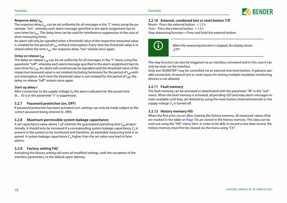
easuring function is stopped, the display shows
0
.2.9 Factory setting FACctivating the factory setting will reset all modified settings, with the exception of the terface parameters, to the default upon delivery.
Functionunction
esponse delay tonhe response delay ton can be set uniformly for all messages in the "t" menu using the pa-meter "ton", whereby each alarm message specified in the alarm assignment has its
wn timer for ton. This delay time can be used for interference suppression in the case of ort measuring times.
n alarm will only be signalled when a threshold value of the respective measured value violated for the period of ton without interruption. Every time the threshold value is vi-lated within the time ton, the response delay "ton" restarts once again.
elay on release toffhe delay on release toff can be set uniformly for all messages in the "t" menu using the arameter "toff", whereby each alarm message specified in the alarm assignment hast its wn timer for toff. An alarm will continuously be signalled until the threshold value of the spective measured value is not violated (including hysteresis) for the period of toff with-
ut interruption. Each time the threshold value is not violated for the period of toff, the elay on release "toff" restarts once again.
tart-up delay tfter connection to the supply voltage US the alarm indication for the preset time …10 s) in the parameter "t" is suppressed.
.2.7 Password protection (on, OFF) password protection has been activated (on), settings can only be made subject to the
rrect password being entered (0...999).
.2.8 Maximum permissible system leakage capacitance set capacitance value above 1 μF extends the guaranteed operating time tae propor-onally. It should only be increased if a corresponding system leakage capacitance Ce is resent in the system to be monitored and therefore, an extended measuring time is re-uired. A system leakage capacitance Ce higher than the set value may lead to false larms.
3.2.10 External, combinReset= Press the external bTest= Press the external buStop measuring function =
The stop function can also bonly be reset via the interfaOnly one ISOMETER® may ballel connection of several tdevices is not allowed.
3.2.11 Fault memoryThe fault memory can be acmenu. When the fault memmain available until they aresupply voltage Us is turned
3.2.12 History memoryWhen the first error occurs aare marked in the table on Pread out using the "HiS" mehistory memory must first b
When the m„STP“.
F
isoUG425_D00220_03_M_XXEN/03.20211
3T
Tth
1
Functionunction
.2.13 Interface/protocolshe ISOMETER® uses the serial hardware interface RS-485 with the following protocols:
• BMS
The BMS protocol is an essential component of the Bender measuring device inter-face (BMS bus protocol). Data transmission generally makes use of ASCII characters.
• Modbus RTU
Modbus RTU is an application layer messaging protocol and it provides Master/Slave communication between devices that are connected altogether via bus systems and networks. Modbus RTU messages have a 16-bit CRC (Cyclic Redundant Checksum), which guarantees reliability.
• IsoData
The ISOMETER® continuously sends an ASCII data string with a cycle of approximate-ly 1 second. Communication with the ISOMETER® within this mode is not possible and no additional transmitter may be connected to the RS-485 bus cable. The ASCII data string for the ISOMETER® is described on Page 27.
he parameter address, baud rate and parity for the interface protocols are configured in e "out" menu.
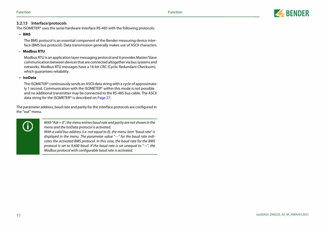
With "Adr = 0", the menu entries baud rate and parity are not shown in themenu and the IsoData protocol is activated.With a valid bus address (i.e. not equal to 0), the menu item "baud rate" isdisplayed in the menu. The parameter value "---" for the baud rate indi-cates the activated BMS protocol. In this case, the baud rate for the BMSprotocol is set to 9,600 baud. If the baud rate is set unequal to "---", theModbus protocol with configurable baud rate is activated.

isoUG425_D00220_03_M_XXEN/03.2021
commissioning4
4
sketches outlining how the device can be screw-mounted connection are shown below:
All dimensions in mm
opened at the lower part marked with an arrow.
93
2
2
1.
2.
3. Click!
& 2 x1 x
100
107
Click
M4
M4!
12
The front plate cover can be
Installation, connection and Installation, connection and commissioning
.1 Mounting • DIN rail mounting:
Snap the mounting clip at the rear of the device onto the DIN rail so that it sits securely or
• Screw mounting:Use a tool to position the rear mounting clips so that they project beyond the enclo-sure (a second mounting clip is required, see ordering information). Fix the device with two M4 screws, see the following sketch.
DANGER
Risk of electric shock!Touching uninsulated live conductors can result in death or serious injury.Therefore avoid any physical contact with active conductors and ensurecompliance with the regulations for working on electrical installations.
If the ISOMETER® is used in rail vehicles, it must be ensured that the ISOME-TER® is installed within a control cabinet that complies with the fire pro-tection requirements of the DIN EN 45545-2.
The dimension diagram andand the push-wire terminal
45
67,5
36
31,147,5
74,5
In
isoUG425_D00220_03_M_XXEN/03.20211
4
Fo
L+
L-
PE
herwiseed.
stallation, connection and commissioning
3
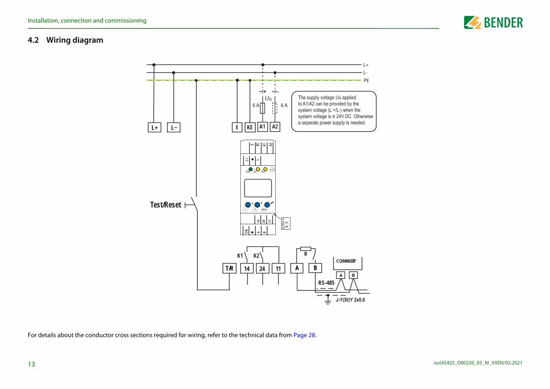
.2 Wiring diagram
r details about the conductor cross sections required for wiring, refer to the technical data from Page 28.
L+ KE
14 24 11
K1 K2
E
T/R
Test/Reset
L
COM460IP
RS-485
A B
R
US
A1 A2
The supply voltage Us applied to A1/A2 can be provided by thesystem voltage (L +/L-) when thesystem voltage is ≥ 24V DC. Ota separate power supply is need
ON AL1 AL2k
T R MENU
Ronoff
14 24 11
AT/R B
L+ L-
E KE A2A1
commissioningIn
isoUG425_D00220_03_M_XXEN/03.20211
W
A
E
L
T
1
1
A
ER® is properly connected to the system to be monitored.
ltage Us to the ISOMETER®. calibration, a self test and adjusts itself to the IT system to be system leakage capacitances are involved, this procedure es. The standard display then appears showing the present g.:
ls an error-free update of the resistance measured value. If not be updated due to disturbances, the pulse symbol will
t by pressing the test button "T". Whilst the test button is (> 1.5 s), all display elements available for this device are the "tES" symbol flashes. Any internal malfunctions detected y as error codes (see Page 8). The alarm relays are not (factory setting). The setting can be changed in the "out" switch to the alarm state during the manual self test.
ings for suitability.e for the installation to be monitored?gs is shown in the tables from Page 16.
ing a genuine insulation fault. the system being monitored against earth, e.g. via a suita-
ble resistance.
4
Installation, connection andstallation, connection and commissioning
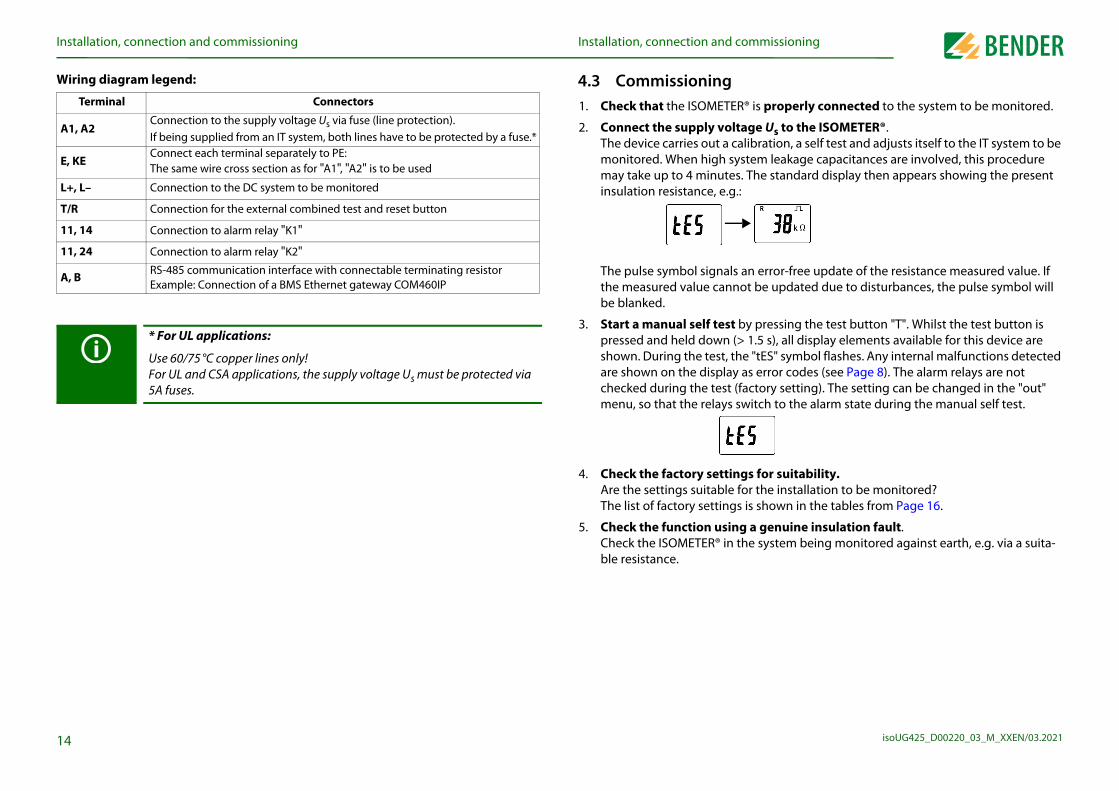
iring diagram legend:
Terminal Connectors
1, A2Connection to the supply voltage Us via fuse (line protection).If being supplied from an IT system, both lines have to be protected by a fuse.*
, KEConnect each terminal separately to PE:The same wire cross section as for "A1", "A2" is to be used
+, L– Connection to the DC system to be monitored
/R Connection for the external combined test and reset button
1, 14 Connection to alarm relay "K1"
1, 24 Connection to alarm relay "K2"
, B RS-485 communication interface with connectable terminating resistorExample: Connection of a BMS Ethernet gateway COM460IP
* For UL applications:
Use 60/75°C copper lines only!For UL and CSA applications, the supply voltage Us must be protected via 5A fuses.
4.3 Commissioning1. Check that the ISOMET
2. Connect the supply voThe device carries out amonitored. When high may take up to 4 minutinsulation resistance, e.
The pulse symbol signathe measured value canbe blanked.
3. Start a manual self tespressed and held downshown. During the test,are shown on the displachecked during the testmenu, so that the relays
4. Check the factory settAre the settings suitablThe list of factory settin
5. Check the function usCheck the ISOMETER® in
isoUG425_D00220_03_M_XXEN/03.2021
5TAa
ts
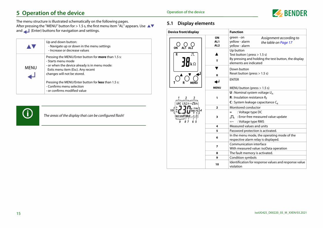
Function
ONAL1AL2
green - onyellow - alarmyellow - alarm
T
Up buttonTest button ( press > 1.5 s)By pressing and holding the test button, the display elements are indicated
R
Down buttonReset button (press > 1.5 s)
MENU
ENTER
MENU button (press > 1.5 s)
1
U : Nominal system voltage UnR : Insulation resistance RFC : System leakage capacitance Ce
2 Monitored conductor
3= : Voltage type DC
=~ : Voltage type RMS 4 Measured values and units5 Password protection is activated.
6In the menu mode, the operating mode of the respective alarm relay is displayed.
7Communication interfaceWith measured value: isoData operation
8 The fault memory is activated.9 Condition symbols
10Identification for response values and response value violation
: Error-free measured value update
Assignment according tothe table on Page 17
15
Operation of the device Operation of the devicehe menu structure is illustrated schematically on the following pages.fter pressing the "MENU" button for > 1.5 s, the first menu item "AL" appears. Use nd (Enter) buttons for navigation and settings.
Up and down button:- Navigate up or down in the menu settings- Increase or decrease values
MENU
Pressing the MENU/Enter button for more than 1.5 s:- Starts menu mode- or when the device already is in menu mode: Exits menu item (Esc). Any recent changes will not be stored.
Pressing the MENU/Enter button for less than 1.5 s:- Confirms menu selection- or confirms modified value
The areas of the display that can be configured flash!
5.1 Display elemen
Device front/display
ON AL1 AL2
T MENUR
+
test onoff MAdr
L1L2C
<>
skM %
Fµ
{ { {{
1 2 3
4
5678
{
9
Hz{
10
O
isoUG425_D00220_03_M_XXEN/03.20211
5
ettingnitor the insulation resistance, "R1" and "R2", can be found in can only be set higher than the value R2. If the insulation re-
elow the activated values R1 or R2, this leads to an alarm mes-s R1 or R2 plus the hysteresis value (see table below), the
parameters ("U <" and "U >") for monitoring the nominal sys-ated or deactivated. The maximum undervoltage value is lim-e.
= Customer settings
Setting value Description
Value range FAC Cs
R2 … 100 50 kΩPre-alarm value Ran1Hys. = 25 %/min. 1 kΩ
1 … R1 25 kΩAlarm value Ran2Hys. = 25 %/min. 1 kΩ
8 … U> 8 VAlarm value undervoltage DCHys . = 5 %/min. 1 V
U< … 144 140 VAlarm value overvoltage DCHys. = 5 %/min. 1 V
6
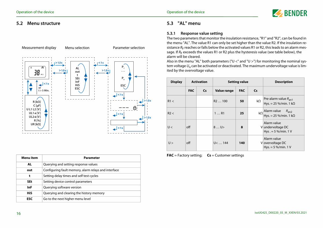
AL Querying and setting response values
out Configuring fault memory, alarm relays and interface
t Setting delay times and self test cycles
SEt Setting device control parameters
InF Querying software version
HiS Querying and clearing the history memory
ESC Go to the next higher menu level
Operation of the deviceperation of the device
.2 Menu structure
Menu item Parameter
< < 1 s1 s
< < 1 s1 s
< < 1 s1 s
P1
. . .
Pn
ESC
> > 1.5 s1.5 s
> > 1.5 s1.5 s
ALout
tSEtInFHiSESC
R [kΩ]C [μF]
U L1 L2 [V ]
UL1 [V ]
UL2 [V ]
R [%]UR [kΩ]
or t > 5 Min.
< < 1 s1 s
k
R> > 1.5 s1.5 s
< < 1 s1 s
> > 1.5 s1.5 s
> > 1.5 s1.5 s
Measurement display Menu selection Parameter selection
5.3 "AL" menu
5.3.1 Response value sThe two parameters that mothe menu "AL". The value R1sistance RF reaches or falls bsage. If RF exceeds the valuealarm will be cleared.Also in the menu "AL" both tem voltage Un can be activited by the overvoltage valu
FAC = Factory setting; Cs
Display Activation
FAC Cs
R1 <
R2 <
U < off
U > off

O
isoUG425_D00220_03_M_XXEN/03.20211
5
5
F
5IntireInsi
r1
r1
r1+R2 < Ω off
+R2 < Ωon Fault R at L+
r1-R
r1U
r1U
= Customer settings on
nfiguration
= Customer settings
ration
omer settings; ified by FAC.
st
off Manually started device test
L
off Device start with alarm
Description
Memory function for alarm messages (fault memory)
value Description
AC Cs
3 ( ) BusAdr.
Adr = 0 deactivates BMS as well as Modbus and activates isoData with continuous data output (115k2, 8E1)
Adr 1 “---“ ( ) Baud rate“---“ : BMS bus (9k6, 7E1)“1.2k“ … “115k“ --> Modbus (variable, var.)
E1 ( )
Mod
bus
8E1 - 8 data bits even parity, 1 stop bit8o1 - 8 data bitsodd parity, 1 stop bit8n1 - 8 data bits no parity, 1 stop bit
K2 "r2" LEDs Alarm descriptionDisplay FAC Cs ON AL1 AL2
7
F
2 < Ω off r2
-R2 < Ωon
Alarm R2 Fault RF at L-
< V off r2
U < Von
Alarm UnDCundervoltage
> V off r2
U > Von
Alarm UnDC Overvoltage
FAC = Factory setting; Cs = Cust( ) = User setting that is not mod
1.2k … 115k
Adr 28E18o18n1
8
Operation of the deviceperation of the device
.4 "out" menu
.4.1 Configuration of the relay operating mode
AC = Factory setting; Cs = Customer settings
.4.2 Relay alarm assignment "r1" and "r2" and LED assignment the alarm assignment, each alarm is assigned to the corresponding relay with the set-
ng "on". The LED indication is directly assigned to the alarms and is not related to the lays. the event of an unsymmetrical insulation fault, only the alarm corresponding to the as-gned conductor (L+ or L-) will be displayed. .
Relay K1 Relay K2 Description
Display FAC Cs Display FAC Cs
n.c. n.c. Operating mode of the relay n.c/n.o.
K1 "r1" K2 "r2" LEDs Alarm descriptionDisplay FAC Cs Display FAC Cs ON AL1 AL2
off on Device error E.xx
+R1 < Ω on r2
+R1 < Ω off Pre-alarm R1 Fault RF at L+
-R1 < Ω on r2 -R1 < Ω off
Pre-alarm R1 Fault RF at L-
r2 Alarm R2
1 2
1 Err 2 Err
FAC = Factory setting; Cs : LED off : LED flashes : LED
5.4.3 Fault memory co
FAC = Factory setting; Cs
5.4.4 Interface configu
r1 test
off r2te
r1 S.AL
off r2S.A
Display FAC Cs
M off
Display Setting
Value range F
Adr 0/3 … 90
--- /
K1 "r1"
Display FAC Cs

O
isoUG425_D00220_03_M_XXEN/03.20211
5
5
F
5
5
F
t
t
t
t
C 1 . . . 50 1 μF
display and history memory on the display (standard display). All other measured value ard display after a maximum of 5 min. The pulse symbol indi-lue. If this symbol does not appear, the measurement is still
measured value will be displayed. The symbols "<" or ">" will the measured value when a response value has been easured value is below or above the measuring range.
ndicated in the history memory.
Description
Insulation resistance RF 1 kΩ ... 1 MΩ Resolution 1 kΩ
Nominal system voltage L+ - L- UnRMS 0 VRMS … 99.9 VRMS Resolution 0.1 VRMS100 VRMS … 150 VRMS Resolution 1 VRMS
Nominal system voltage L+ - L- UnDC 0 VDC … 99.9 VDC Resolution 0.1 VDC100 VDC … 150 VDC Resolution 1 VDC
Residual voltage L+ - PE UL+e 0 VDC … 99.9VDC Resolution 0.1 VDC100 VDC … 150 VDC Resolution 1 VDC
Residual voltage L- - PE UL-e 0 VDC … 99.9VDC Resolution 0.1 VDC100 VDC … 150 VDC Resolution 1 VDC
8
AC = Factory setting; Cs = Customer settings
leakage capacitance Ce
S.Ct on Device test during device start
FAC Restore factory settings
SYS For Bender Service only
Operation of the deviceperation of the device
.5 "t" menu
.5.1 Time configuration
AC = Factory setting; Cs = Customer settings
.6 "SEt" menu
.6.1 Function configuration
Display Setting value Description
Value range FAC Cs
0 … 10 0 s Start-up time when starting the device
on 0 … 99 0 s Response delay K1 and K2
off 0 … 99 0 s Delay on release K1 and K2
est OFF/1/24 24 h Repetition time device test
Display Activation Setting value Description
FAC Cs Value range FAC Cs
off 0 . . . 999 0 Password for parameter setting
Maximum permissible system
5.7 Measured valueRF is continuously indicateddisplays switch to the standcates a current measured varunning and the latest validbe displayed additionally toreached or violated or the m
: The measured value is i
HiS Display
R kΩ
U L1 L2 =~ V
U L1 L2 = V
±U L1 = V
±U L2 = V
isoUG425_D00220_03_M_XXEN/03.2021
rotocol6T(B
19
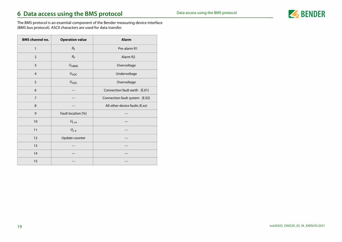
Data access using the BMS p Data access using the BMS protocolhe BMS protocol is an essential component of the Bender measuring device interface MS bus protocol). ASCII characters are used for data transfer.
BMS channel no. Operation value Alarm
1 RF Pre-alarm R1
2 RF Alarm R2
3 UnRMS Overvoltage
4 UnDC Undervoltage
5 UnDC Overvoltage
6 --- Connection fault earth (E.01)
7 --- Connection fault system (E.02)
8 --- All other device faults (E.xx)
9 Fault location [%] ---
10 UL+e ---
11 UL-e ---
12 Update counter ---
13 --- ---
14 --- ---
15 --- ---

isoUG425_D00220_03_M_XXEN/03.2021
us RTU protocol7RRa
7Tthnb
7Intech
7
B
B
B
B
B
B
B
bus register (parameter setting)e modified with the function code 0x10 (Write Multiple
ers are available from address 3000. The content of the on Page 22.
Master to the ISOMETER®addresses the ISOMETER® with address 3 and requests that
ith address 3003 is set to 2.
nswers the Master
Name Example
odbus address 0x03
e 0x10
0x0BBB
gisters 0x0001
ta bytes 0x02
0x0002
sum 0x9F7A
Name Example
odbus address 0x03
e 0x10
0x0BBB
gisters 0x0001
sum 0x722A
20
Byte 2 Number of data bytes 0x02
Byte 3, 4 Data 0x0047
Byte 7, 8 CRC16 Checksum 0x81B6
Byte 6, 7 CRC16 Check
Data access using the Modb Data access using the Modbus RTU protocolequests to the ISOMETER® can be made using the function code 0x03 (Read Multiple egisters) or the function code 0x10 (Write Multiple Registers). The ISOMETER® generates function-related answer and sends it back.
.1 Reading out the Modbus register from the ISOMETER®he required Words of the process image can be read out from the "Holding registers" of e ISOMETER® using the function code 0x03. For this purpose, the start address and the
umber of the registers to be read out have to be entered. Up to 125 Words (0x7D) can e read with one single request.
.1.1 Command of the master to the ISOMETER® the following example, the master of the ISOMETER® requests the content of the regis-r 1003 with the address 3. The register contains the channel description of measuring annel 1.
.1.2 The ISOMETER® answers the Master
Byte Name Example
yte 0 ISOMETER® Modbus address 0x03
yte 1 Function code 0x03
yte 2, 3 Start address 0x03EB
yte 4, 5 Number of registers 0x0001
yte 6, 7 CRC16 Checksum 0xF598
Byte Name Example
yte 0 ISOMETER® Modbus address 0x03
yte 1 Function code 0x03
7.2 Writing the ModRegisters in the device can bRegisters). Parameter registregister is listed in the table
7.2.1 Command of theIn this example, the master the content of the register w
7.2.2 The ISOMETER® a
Byte
Byte 0 ISOMETER® M
Byte 1 Function cod
Byte 2, 3 Start register
Byte 4, 5 Number of re
Byte 6 Number of da
Byte 7, 8 Data
Byte 9, 10 CRC16 Check
Byte
Byte 0 ISOMETER® M
Byte 1 Function cod
Byte 2, 3 Start register
Byte 4, 5 Number of re

us RTU protocolD
isoUG425_D00220_03_M_XXEN/03.20212
7Ife
7
0
0
0
0
0
0
B
B
B
B
1
Data access using the Modbata access using the Modbus RTU protocol
.3 Exception code a request cannot be answered for whatever reason, the ISOMETER® will send a so-called xception code with which possible faults can be narrowed down.
.3.1 Structure of the exception code
Exception code Description
x01 Impermissible function
x02 Impermissible data access
x03 Impermissible data value
x04 Internal fault
x05 Acknowledgement of receipt (answer will be time delayed)
x06 Request not accepted (repeat request if necessary)
Byte Name Example
yte 0 ISOMETER® Modbus address 0x03
yte 1 Function code (0x03) + 0x80 0x83
yte 2 Data (exception code) 0x04
yte 3, 4 CRC16 Checksum 0xE133
isoUG425_D00220_03_M_XXEN/03.2021
t of the ISOMETER®8Duo
R
de (refer to Chapter 8.2)apter 8.1.2.2)
--- ------
Device error (115)[device fault]
Description Format Unit Value range
Reserved --- --- ---
Reserved --- --- ---
Reserved --- --- ---
Reserved --- --- ---
Reserved --- --- ---
Pre-alarm value resistance measure-
ment "R1"UINT 16 kΩ R2 … 100
Reserved --- --- ---
Alarm value resist-ance measurement
"R2"UINT 16 kΩ 1 … R1
Activation alarm value undervoltage
DC "U<"UINT 16 ---
0 = Inactive1 = Active
Alarm value under-voltage DC "U<"
UINT 16 1/10 V 80 … U>
Activation alarm value overvoltage
DC "U>"UINT 16 ---
0 = Inactive1 = Active
Alarm value Overvoltage DC
"U >"UINT 16 1/10 V U< … 1440
Measured valueDevice fault
Alarm 1 Alarm 2
22
1024 to
1027
Fault location in % --- (1022)
[no alarm]--- --- ---
1028 to
1031---
--- --- ---
3009 RW
3010 RW
3011 RW
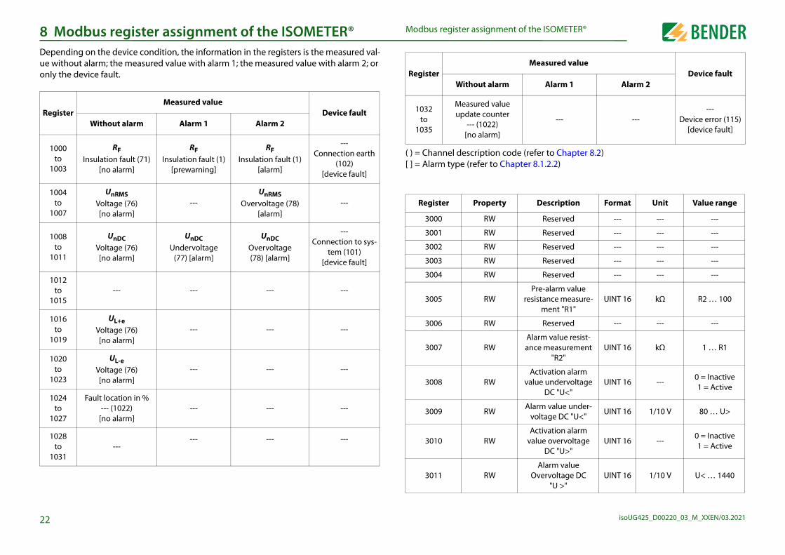
Modbus register assignmen Modbus register assignment of the ISOMETER®epending on the device condition, the information in the registers is the measured val-e without alarm; the measured value with alarm 1; the measured value with alarm 2; or nly the device fault.
egisterMeasured value
Device faultWithout alarm Alarm 1 Alarm 2
1000 to
1003
RFInsulation fault (71)
[no alarm]
RFInsulation fault (1)
[prewarning]
RFInsulation fault (1)
[alarm]
--- Connection earth
(102)[device fault]
1004 to
1007
UnRMSVoltage (76)[no alarm]
---UnRMS
Overvoltage (78)[alarm]
---
1008 to
1011
UnDCVoltage (76)[no alarm]
UnDCUndervoltage
(77) [alarm]
UnDCOvervoltage(78) [alarm]
---Connection to sys-
tem (101)[device fault]
1012 to
1015--- --- --- ---
1016 to
1019
UL+eVoltage (76)[no alarm]
--- --- ---
1020 to
1023
UL-eVoltage (76)[no alarm]
--- --- ---
( ) = Channel description co[ ] = Alarm type (refer to Ch
1032 to
1035
Measured value update counter
--- (1022) [no alarm]
Register Property
3000 RW
3001 RW
3002 RW
3003 RW
3004 RW
3005 RW
3006 RW
3007 RW
3008 RW
RegisterWithout alarm
OMETER®
isoUG425_D00220_03_M_XXEN/03.20212
and "K2"
ad only; WO = Write only
um permissi-tem leakage citance Ce
UINT 16 μF
1 1020...50
served --- --- ---
test during start "S. Ct"
UINT 16 ---0 = Inactive1 = Active
stop mode (0 ivate device)
UINT 16 ---0 = Stop
1 = ---
ssignment of ay 1 "r1"
UINT 16 --- Bit 9 … Bit 1
ssignment of ay 2 "r2"
UINT 16 --- Bit 9 … Bit 1
setting for all ameters
UINT 16 --- 0x6661 „fa“
setting only meters reset-le by FAC
UINT 16 --- 0x4653 "FS"
device test UINT 16 --- 0x5445 "TE"
ult memory UINT 16 --- 0x434C "CL"
ice name
UNIT 16 (ASCII) - refer to Chapter
8.1.1
--- ---
Software ID number
UINT 16 ---Software D
number
Software version number
UINT 16 ---Software ver-
sion
Software version: Year UINT 16
Software version: Month
UINT 16
Software version: Day UINT 16
Modbus driver ver-sion
UINT 16
cription Format Unit Value range
3
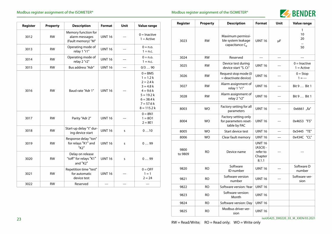
3021 RWRepetition time "test"
for automatic device test
UINT 16 ---0 = OFF
1 = 1 2 = 24
3022 RW Reserved --- --- ---
RW = Read/Write; RO = Re
9820 RO
9821 RO
9822 RO
9823 RO
9824 RO
9825 RO
Modbus register assignment of the ISModbus register assignment of the ISOMETER®
3012 RWMemory function for
alarm messages(Fault memory) "M"
UINT 16 ---0 = Inactive1 = Active
3013 RWOperating mode of
relay 1 "r1"UINT 16 ---
0 = n.o. 1 = n.c.
3014 RWOperating mode of
relay 2 "r2"UINT 16 ---
0 = n.o. 1 = n.c.
3015 RW Bus address "Adr" UINT 16 --- 0/3 … 90
3016 RW Baud rate "Adr 1" UINT 16 ---
0 = BMS 1 = 1.2 k 2 = 2.4 k 3 = 4.8 k 4 = 9.6 k
5 = 19.2 k 6 = 38.4 k 7 = 57.6 k
8 = 115.2 k
3017 RW Parity "Adr 2" UINT 16 ---0 = 8N1 1 = 8O1 2 = 8E1
3018 RWStart-up delay "t" dur-
ing device startUINT 16 s 0 …10
3019 RWResponse delay "ton"
for relays "K1" and "K2"
UINT 16 s 0 … 99
3020 RWDelay on release
"toff" for relays "K1" UINT 16 s 0 … 99
Register Property Description Format Unit Value range
3023 RWMaximble sys
capa
3024 RW Re
3025 RWDevicedevice
3026 RWRequest= deact
3027 RWAlarm a
rel
3028 RWAlarm a
rel
8003 WOFactory
par
8004 WOFactory
for paratab
8005 WO Start
8006 WO Clear fa
9800 to 9809
RO Dev
Register Property Des

t of the ISOMETER®M
isoUG425_D00220_03_M_XXEN/03.20212
8
8T
8EmCe
8
RIESEM
S E E E E E E E E M M M M M M M M M M M M M M M M M M M M M M M
e and test type (internal/external)
by the bits 0 to 2.
ed and always have the value 0.
hen an internal or external test has been completed.
he complete byte is calculated from the sum of the alarm type
4 3 2 1 0 Meaning
Rese
rved
Rese
rved
Ala
rm
Faul
t
X X 0 0 0 No alarm
X X 0 0 1 Prewarning
X X 0 1 0 Device fault
X X 0 1 1 Reserved
X X 1 0 0 Warning
X X 1 0 1 Alarm
X X 1 1 0 Reserved
X X … … … Reserved
X X 1 1 1 Reserved
X X X X X No test
X X X X X Internal test
X X X X X External test
4
epresentation of the bit order for processing analogue measured values according to EE 754
= Sign = Exponent = Mantissa
and the test type.
Modbus register assignmenodbus register assignment of the ISOMETER®
.1 Device-specific data type of the ISOMETER®
.1.1 Device namehe data format of the device name is specified below.
.1.2 Measured valuesach measured value is available as a channel and consists of 8 bytes (4 registers). The first easured value register address is 1000. The structure of a channel is always identical.
ontent and number depend on the device. The structure of a channel is shown with the xample of channel 1:
.1.2.1 Float = Floating point value of the channels
Word0x00
0x01 0x02 0x03 ------------------- 0x08 0x09
10 Words in totalEach Word contains two ASCII characters
1000 1001 1002 1003
HiByte LoByte HiByte LoByte HiByte LoByte HiByte LoByte
Floating point value (Float)Alarm type and
test type (AT&T)
Range and unit (R&U)
Channel description
Wor
d
0x00 0x01
Byt
e HiByte LoByte HiByte LoByte
Bit 31 30 24 23 22 16 15 8 7 0
8.1.2.2 AT&T = Alarm typ
• The alarm type is coded
• Bits 3, 4 and 5 are reserv
• Bit 6 or 7 is usually set w
Other values are reserved. T
Bit 7 6 5
Tes
t ext
erna
l
Tes
t int
erna
l
Rese
rved
Ala
rm ty
pe
X X X
X X X
0 0 X
X X X
X X X
X X X
X X X
X X X
X X X
Test
0 0 X
0 1 X
1 0 X

t of the ISOMETER®M
isoUG425_D00220_03_M_XXEN/03.20212
8
• Bits 6 and 7 describe the validity range of a value.
T
8Srere
fied function.
Meaning
When reading, always 0 When writing, any value
Device error E.xx
Pre-alarm R1 - fault RF at L+
Pre-alarm R1 - fault RF at L-
Pre-alarm R2 - fault RF at L+
Pre-alarm R2 - fault RF at L-
Alarm message Un - undervoltage
Alarm message Un - overvoltage
Manually started self test
Device start with alarm
When reading, always 0 When writing, any value
When reading, always 0 When writing, any value
When reading, always 0 When writing, any value
When reading, always 0When writing, any value
When reading, always 0 When writing, any value
When reading, always 0 When writing, any value
5
• Bit 5 is reserved.
he complete byte is calculated from the sum of the unit and the range of validity.
.1.3 Alarm assignment of the relays everal alarms can be assigned to each relay. For the assignment of each relay, a 16-bit gister is used with the bits described below. The following table applies to relay 1 and lay 2, in which "x" stands for the relay number. A set bit activates the specified function.
13 Reserved
14 Reserved
15 Reserved
Modbus register assignmenodbus register assignment of the ISOMETER®
.1.2.3 R&U = Range and unit
• The units of bits 0 to 4 are coded.
Bit 7 6 5 4 3 2 1 0 Meaning
Un
it
- - - 0 0 0 0 0 Invalid (init)
- - - 0 0 0 0 1 No unit
- - - 0 0 0 1 0 Ω
- - - 0 0 0 1 1 A
- - - 0 0 1 0 0 V
- - - 0 0 1 0 1 %
- - - 0 0 1 1 0 Hz
- - - 0 0 1 1 1 Baud
- - - 0 1 0 0 0 F
- - - 0 1 0 0 1 H
- - - 0 1 0 1 0 °C
- - - 0 1 0 1 1 °F
- - - 0 1 1 0 0 Second
- - - 0 1 1 0 1 Minute
- - - 0 1 1 1 0 Hour
- - - 0 1 1 1 1 Day
- - - 1 0 0 0 0 Month
Ran
ge
of v
alid
ity 0 0 X X X X X X Actual value
0 1 X X X X X X The actual value is lower
1 0 X X X X X X The actual value is higher
1 1 X X X X X X Invalid value
A set bit activates the speci
Bit Display indication
0 Reserved
1 x Err
2 rx +R1 < Ω
3 rx -R1 < Ω
4 rx +R2 < Ω
5 rx -R2 < Ω
6 rx U < V
7 rx U > V
8 rx test
9 rx S.AL
10 Reserved
11 Reserved
12 Reserved

t of the ISOMETER®M
isoUG425_D00220_03_M_XXEN/03.20212
8 data type descriptions are required. Text representation is not
Description of parameters
/measured value invalid. item of this parameter is not displayed.
red value/no message
value/parameter inactive
value/parameter only temporarily inactive (e.g. while transmitting meter). Indication in the menu "…".
/measured value (value) unit not displayed
(code selection menu) unit not displayed
. 18 characters (e.g. device type, device variant, …)
th
dress (unit not displayed)
ltiplication [*]
sion [/]
6
1008 (0x3F0) Factor divi
1007 (0x3EF) Baud rate
1022 (0x3FE)
1023 (0x3FF) Invalid
Modbus register assignmenodbus register assignment of the ISOMETER®
.2 Channel descriptions
ValueMeasured value description/
alarm message operating message
Note
0
1 (0x01) Insulation fault
71 (0x47) Insulation fault Insulation resistance RF in Ω
76 (0x4C) Voltage Measured value in V
77 (0x4D) Undervoltage
78 (0x4E) Overvoltage
82 (0x52) Capacitance Measured value in F
86 (0x56) Insulation fault Impedance Zi
101 (0x65) Connection system
102 (0x66) Connection earth
115 (0x73) Device fault Fault ISOMETER®
129 (0x81) Device fault
145 (0x91) Own address
To convert parameter data, necessary in this case.
Value
1023 (0x3FF) ParameterThe menu
1022 (0x3FE) No measu
1021 (0x3FD) Measured
1020 (0x3FC) Measured a new para
1019 (0x3FB) Parameter
1018 (0x3FA) Parameter
1017 (0x3F9) String max
1016 (0x3F8)
1015 (0x3F7) Time
1014 (0x3F6) Date: Day
1013 (0x3F5) Date: Mon
1012 (0x3F4) Date: Year
1011 (0x3F3) Register ad
1010 (0x3F2) Time
1009 (0x3F1) Factor mu

isoUG425_D00220_03_M_XXEN/03.2021
9 ItipIsto
n
27
0x0080 Alarm overvoltage Un0x0100 Message system test0x0200 Device start with alarm
1Update counter, consecutively counts from 0 to 999.It increases with the update of the insulation resistance value.
<CR><LF> String end
IsoData data string IsoData data stringn IsoData mode, the ISOMETER® continuously sends the whole data string with a cycle me of approximately 1 second. Communication with the ISOMETER® in this mode is not ossible and no additional sender may be connected via the RS-485 bus cable.oData is activated in the menu item "Adr" in the "out" menu when the menu item is set Adr = 0. In this event, the symbol "Adr" flashes on the measured value display.
String Description
!; Start symbol
v; Insulation fault location ' ' / '+' / '-'
1234, 5; Insulation resistance RF [kΩ]
12345,6; Nominal system voltage Un [VRMS]
+1234, 5; Nominal system voltage Un [VDC]
+1234,5; Residual voltage UL+e [VDC]
+1234,5; Residual voltage UL-e [VDC]
1234;
Alarm message [hexadecimal] (without leading "0x")
The alarms are included in this value with the OR function.
Assignment of the alarms:0x0002 Device fault 0x0004 Prewarning insulation resistance RF at L+0x0008 Prewarning insulation resistance RF at L-0x0010 Alarm insulation resistance RF at L+0x0020 Alarm insulation resistance RF at L-0x0040 Alarm undervoltage U
isoUG425_D00220_03_M_XXEN/03.2021
1
1(
InD
RaOvRa
Ra
PoPr
Vo
SSuTo
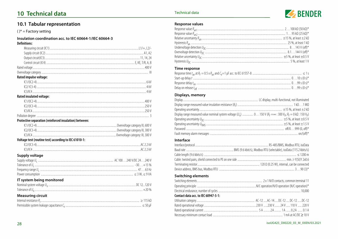
......................................................................................... 2…100 kΩ (50 kΩ)*
........................................................................................... 1…95 kΩ (25 kΩ)*
...................................................................................... ±15 %, at least ±2 kΩ
............................................................................................. 25 %, at least 1 kΩ
................................................................................................ 8…143 V (off)*
............................................................................................. 8.1…144 V (off)*
....................................................................................... ±5 %, at least ±0.5 V
................................................................................................. 5 %, at least 1 V
1 μF acc. to IEC 61557-8 ........................................................................ ≤ 1 s................................................................................................... 0…10 s (0 s)*................................................................................................... 0…99 s (0 s)*................................................................................................... 0…99 s (0 s)*
................................................... LC display, multi-functional, not illuminatedistance (RF) ................................................................................. 1 kΩ…1 MΩ
...................................................................................... ±15 %, at least ±2 kΩem voltage (Un) ................ 0…150 V (RF =∞ : 300 VP; RF = 0 kΩ : 150 VP)....................................................................................... ±5 %, at least ±0.5 V........................................................................................ ±5 %, at least ±1.5 V......................................................................................... off/0…999 (0, off)*............................................................................................................. on/(off)*
.................................................................. RS-485/BMS, Modbus RTU, isoData
............... BMS (9.6 kbit/s), Modbus RTU (selectable), isoData (115.2 kbits/s)
........................................................................................................... ≤ 1200 m on one side ....................................................................... min. J-Y(St)Y 2x0.6..................................................... 120 Ω (0.25 W), internal, can be connected
Device address, BMS bus, Modbus RTU .............................................................................................................. 3…90 (3)*
............................................................ 2 x 1 N/O contacts, common terminal 11
...................................................N/C operation/N/O operation (N/C operation)*
.................................................................................................................... 10,000
................................................. AC-12 .....AC-14 ..... DC-12 ..... DC-12 ......DC-12
...................................................230 V ......230 V........ 24 V ......110 V ...... 220 V
...................................................... 5 A ..........2 A .......... 1 A .......0.2 A ....... 0.1 A
.......................................................................................... 1 mA at AC/DC ≥ 10 V
28
Frequency range Us .............................................................................................................................................. 47…63 HzPower consumption ....................................................................................................................................... ≤ 3 W, ≤ 9 VA
IT system being monitoredNominal system voltage Un ................................................................................................................................ DC 12...120 VTolerance of Un .............................................................................................................................................................. +20 %
Measuring circuitInternal resistance Ri................................................................................................................................................. ≥ 115 kΩPermissible system leakage capacitance Ce ............................................................................................................... ≤ 50 μF
Switching elementsSwitching elements ...................................Operating principle ...................................Electrical endurance, number of cycles ....Contact data acc. to IEC 60947-5-1:Utilisation category....................................Rated operational voltage .........................Rated operational current .........................Necessary minimum contact load ............
Technical data0 Technical data
0.1 Tabular representation)* = Factory setting
sulation coordination acc. to IEC 60664-1/IEC 60664-3 efinitions:
Measuring circuit (IC1) ..................................................................................................................................L1/+, L2/-Supply circuit (IC2) ............................................................................................................................................... A1, A2Output circuit(IC3)...........................................................................................................................................11, 14, 24Control circuit (IC4) ................................................................................................................................. E, KE, T/R, A, B
ted voltage....................................................................................................................................................................400 Vervoltage category ............................................................................................................................................................ IIIted impulse voltage:
IC1/(IC2-4)................................................................................................................................................................ 6 kVIC2/ IC3-4) ................................................................................................................................................................ 4 kVIC3/IC4 ...................................................................................................................................................................... 4 kV
ted insulated voltage:IC1/(IC2-4)..............................................................................................................................................................400 VIC2/(IC3-4)..............................................................................................................................................................250 VIC3/IC4 ....................................................................................................................................................................250 V
llution degree .................................................................................................................................................................... 3otective separation (reinforced insulation) between:
IC1/(IC2-4).....................................................................................................................Overvoltage category III, 600 VIC2/(IC3-4).....................................................................................................................Overvoltage category III, 300 VIC3/IC4 ..........................................................................................................................Overvoltage category: III, 300 V
ltage test (routine test) according to IEC 61010-1: IC2/(IC3-4)........................................................................................................................................................AC 2.2 kV
IC3/IC4 ..............................................................................................................................................................AC 2.2 kV
upply voltagepply voltage Us .............................................................................................................. AC 100…240 V/DC 24…240 Vlerance of Us ................................................................................................................................................. -30…+15 %
Response valuesResponse value Ran1 .....................................Response value Ran2 .....................................Relative uncertainty Ran................................Hysteresis Ran ...............................................Undervoltage detection UDC.........................Overvoltage detection UDC ...........................Relative uncertainty UDC ...............................Hysteresis UDC ..............................................
Time responseResponse time tan at RF = 0.5 x Ran and Ce=Start-up delay t ............................................Response delay ton .......................................Delay on release toff .....................................
Displays, memoryDisplay...........................................................Display range measured value insulation resOperating uncertainty...................................Display range measured value nominal systOperating uncertainty UDC............................Operating uncertainty URMS .........................Password ......................................................Fault memory alarm messages ...................
InterfaceInterface/protocol .........................................Baud rate ......................................................Cable length (9.6 kbits/s) ............................Cable: twisted pairs, shield connected to PETerminating resistor......................................

T
isoUG425_D00220_03_M_XXEN/03.20212
EEMAmOpTrStClStTrLoClStTrLo
CCoNoCrStRiFlfleMOpTe
OOpMDeDegree of protection, terminals (DIN EN 60529) ............................................................................................................. IP20EnDIScW
rovals and certificationsveloped in compliance with the following standards:
ified standards take into account the edition valid until dicated.
ation
25 is not an insulation monitoring device as described7-8/EN 61557-8. It records insulation faults that cause
etry to PE in the IT system. Symmetrical insulation faultsrecorded.
Version Art. No.
terminal B71036320
B98060008
9
closure material ..............................................................................................................................................polycarbonateN rail mounting acc. to........................................................................................................................................... IEC 60715rew fixing .................................................................................................................................. 2 x M4 with mounting clipeight ..........................................................................................................................................................................≤ 150 g
Technical dataechnical data
nvironment/EMCC .................................................................................................................................................................... IEC 61326-2-4bient temperatures:
eration ......................................................................................................................................................... -40…+70 ºCansport .......................................................................................................................................................... -40…+85 ºCorage ............................................................................................................................................................. -40…+70 ºCassification of climatic conditions acc. to IEC 60721ationary use (IEC 60721-3-3) ................................................................3K24 (except condensation and formation of ice)ansport (IEC 60721-3-2) ...................................................................... 2K11 (except condensation and formation of ice)ng-term storage (IEC 60721-3-1) .......................................................1K22 (except condensation and formation of ice)assification of mechanical conditions acc. to IEC 60721ationary use (IEC 60721-3-3) ......................................................................................................................................3M11ansport (IEC 60721-3-2) ............................................................................................................................................... 2M4ng-term storage (IEC 60721-3-1) ............................................................................................................................. 1M12
onnectionnnection type......................................................................................................................................... push-wire terminalminal current............................................................................................................................................................. ≤ 10 A
oss section ..........................................................................................................................................................AWG 24 -14ripping length............................................................................................................................................................. 10 mmgid ..................................................................................................................................................................0.2…2.5 mm2
exible without ferrules................................................................................................................................ 0.75…2.5 mm2
xible with ferrules with/without plastic sleeve ....................................................................................... 0.25…2.5 mm2
ulti-conductor flexible with TWIN ferrules with plastic sleeve ...................................................................0.5…1.5 mm2
ening force .................................................................................................................................................................... 50 Nst opening, diameter ............................................................................................................................................... 2.1 mm
thererating mode .................................................................................................................................... continuous operation
ounting .............................................................................................................. cooling slots must be ventilated verticallygree of protection, built-in components (DIN EN 60529) .......................................................................................... IP30
10.2 Standards, appThe ISOMETER® has been de
• DIN EN 50155
Subject to change! The spec03.2021 unless otherwise in
10.3 Ordering inform
The isoUG4in IEC 6155an asymmcannot be
Type
isoUG425-D4-4 Push-wire
Mounting clip for screw fixing(1 piece per device)

T
isoUG425_D00220_03_M_XXEN/03.20213
1
0
Technical dataechnical data
0.4 Document revision history
Date Document version
Valid from software version State/Changes
03.2021 03 D0476 V2.22
Editorial revisionAdded:Chapter 3.2.10: Note on stoppedmeasuring functionChanged:Chapter 4.2: Wiring diagramChapter 5.2: Menu overview representationAdded:Chapter 8: Modbus register 8003Corrected:Chapter 10.1: Term „Necessary minimumcontact load“, climatic/mechanicalclassificationsAdded:Chapter 10.2: UKCA certificateRevision history

isoUG425_D00220_03_M_XXEN/03.2021
I
CCC
DD
DDD
EE
FFFF
H
ection 12
ent 22
and overvoltage 8nce (R mode) 8
n 29
10
31
History memory 10, 18How to use this manual 5
Operating time 9Operation 15Ordering informatio
PPassword protection
NDEX
ommissioning 14onfiguration
Fault memory 17Function 18Interface 17Relay operating mode 17Time 18
ata accessBMS 19Modbus RTU 20
elay on release 10evice features 8isplay elements 15
rror codes 9
actory setting 10ault memory 10unction description 8
IInstallation and connInterface/protocols
BMS 11IsoData 11Modbus RTU 11
IsoDataData string 27
MMalfunction 9Measuring times 9Menu
"AL" 16"out" 17"SEt" 18"t" 18Overview 16
ModbusRegister assignm
Monitoringfor undervoltageinsulation resista
O

isoUG425_D00220_03_M_XXEN/03.202132
RRelayReseRespRespResp
SSafetSelf t
AM
SignaStart
TTechTotal
WWirinWork
alarm assignment 17t button T/R 10onse delay 10onse times 9onse value setting 16
y instructions 7est 8utomatic 9anual 9lling assignment of the alarm relays K1/K2 9
-up delay 10
nical data 28 response time 9
g diagram 13 activities on electrical installations 7

Fotos: Bender Archiv.
Customer serviceService hotline: 0700-BenderHelp (Telephone and Fax)Carl-Benz-Straße 8 • 35305 Grünberg • Germany
Tel.: +49 6401 807-760Fax: +49 6401 807-629
E-Mail: [email protected]: https://www.bender.de BENDER Group
Bender GmbH & Co. KGPO box 1161 • 35301 Grünberg • GermanyLondorfer Straße 65 • 35305 Grünberg • Germany
Tel.: +49 6401 807-0Fax: +49 6401 807-259
E-Mail: [email protected]: www.bender.de