isolation of tpws - indian railwayrdso.indianrailways.gov.in/works/uploads/file/reasoned document...
TRANSCRIPT
Reasoned Document for RDSO/SPN/183/2011 version -2 Page 1 of 40
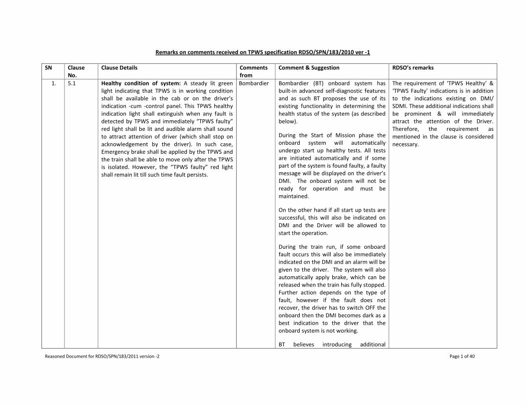
Remarks on comments received on TPWS specification RDSO/SPN/183/2010 ver -1
SN Clause
No.
Clause Details Comments
from
Comment & Suggestion RDSO’s remarks
1. 5.1 Healthy condition of system: A steady lit green
light indicating that TPWS is in working condition
shall be available in the cab or on the driver’s
indication -cum -control panel. This TPWS healthy
indication light shall extinguish when any fault is
detected by TPWS and immediately “TPWS faulty”
red light shall be lit and audible alarm shall sound
to attract attention of driver (which shall stop on
acknowledgement by the driver). In such case,
Emergency brake shall be applied by the TPWS and
the train shall be able to move only after the TPWS
is isolated. However, the “TPWS faulty” red light
shall remain lit till such time fault persists.
Bombardier Bombardier (BT) onboard system has
built-in advanced self-diagnostic features
and as such BT proposes the use of its
existing functionality in determining the
health status of the system (as described
below).
During the Start of Mission phase the
onboard system will automatically
undergo start up healthy tests. All tests
are initiated automatically and if some
part of the system is found faulty, a faulty
message will be displayed on the driver’s
DMI. The onboard system will not be
ready for operation and must be
maintained.
On the other hand if all start up tests are
successful, this will also be indicated on
DMI and the Driver will be allowed to
start the operation.
During the train run, if some onboard
fault occurs this will also be immediately
indicated on the DMI and an alarm will be
given to the driver. The system will also
automatically apply brake, which can be
released when the train has fully stopped.
Further action depends on the type of
fault, however if the fault does not
recover, the driver has to switch OFF the
onboard then the DMI becomes dark as a
best indication to the driver that the
onboard system is not working.
BT believes introducing additional
The requirement of ‘TPWS Healthy’ &
‘TPWS Faulty’ indications is in addition
to the indications existing on DMI/
SDMI. These additional indications shall
be prominent & will immediately
attract the attention of the Driver.
Therefore, the requirement as
mentioned in the clause is considered
necessary.

Reasoned Document for RDSO/SPN/183/2011 version -2 Page 2 of 40
components as e.g. lamps and switches
for healthy indication will require
additional maintenance in the future and
will in any case have some impact on
system MTBF and reliability. In this
regard, BT believes it is better to avoid
adding extra indication lamps and just
fulfil this requirement with the
functionality described above.
2. 5.8.1 TPWS shall continuously compare the current
speed of train with the permitted speed at all
locations in all those modes in which speed
monitoring is available except for release speed
monitoring. A warning must be given to the driver
to enable him to react and avoid intervention from
TPWS before the application of service brake. The
following actions shall be taken by TPWS depending
upon the difference in current train speed &
permitted speed:
------
------
------
The system shall have provision of configuring the
speed limits/ slabs as mentioned in column 2 of the
above table, by the purchaser. However, these
speed limits shall be in multiples of 5 KMPH or less.
Bombardier BT onboard system fully complies with
Subset – 26 v2.3.0 regarding these
parameters and furthermore actual
implementation in assigning these values
can be further discussed with the end
customer.
These requirements comply with ETCS
standards. Any deviation with this
specification shall be specifically
brought out. However, clause is
modified.
3. 5.14 Isolation of TPWS: System shall have provision so
that TPWS is bypassed in case of failure situation.
Isolation of the entire train borne equipment must
result in disconnection of the system from the
vehicle braking system. This shall be indicated to
the driver by means of a visual indication which
shall be available even if SDMI/DMI has failed. To
avoid accidental/ unwarranted use, the isolation
arrangement of the equipment must be protected
and sealed. Isolation of system must be recorded
by the system as well as recorded in a non-
resettable veeder counter.
Bombardier During isolation of the onboard system
(by mean of Isolation Switch) all
connection to the brake system will be
bypassed and additional EB SIFA valve will
be energized by the vehicle battery.
Isolation of the system is indicated to the
driver by means of a dark DMI.
However if this is not considered as
sufficient, an additional contact can be
The requirement is based on clause no.
4.1.6.3a of ETCS FRS ver.4 .50.
The clause details as “A clear indication
shall be given to the driver, that ETCS
has been isolated, even if the normal
ETCS DMI is defective.”
Indication of TPWS isolation is required
even in case of DMI/SDMI failure e.g.
blanking of DMI screen.

Reasoned Document for RDSO/SPN/183/2011 version -2 Page 3 of 40
implemented into the isolation switch
and an alarm lamp can be then lit. This is
a matter for further discussion with the
customer as introducing any additional
components will require extra
maintenance and decrease reliability.
Isolation switch can be sealed to prevent
unauthorized isolations.
All isolation will be recorded by proposed
JRU and the stored data inside JRU can
not be erased nor manipulated by
unauthorized personnel.
Non-resettable counter is also
necessary so that even without
downloading the data from JRU,
number of EB application cases could
be known.
4. 6.7.2 Where required by the purchaser, an atleast 8
position switch to select the configuration of
different train characteristics predefined based on
maximum permissible speed, train load, brake
characteristics & any other relevant considerations.
Bombardier Such a mechanical switch is not required
by Bombardier onboard system. All fixed
train data parameters are entered during
the installation phase onboard, while
variable parameters can be entered by
the driver using keys on DMI (touch-
screen buttons) according to UNISIG
ERTMS standard.
Below is the list of the variable
parameters that can be entered by the
driver using the DMI during start-up:
Alternative 1.
ATP installed for “fixed train data entry”,
permits the driver to select the type of
train/train configuration from a menu at
the DMI that corresponds to the train he
is going to start-up.
The selected train type includes all
relevant train data needed for the ATP.
Driver chooses and approves the correct
selection.
Alternative 2.
ATP installed for “flexible train data
entry”, permits the driver to individually
select the value of the train data menu
Provision of 8-position switch has not
been considered necessary for
CENELEC DMI. However, the same
would be required for SDMI. (Clause
6.18 of ver-2)

Reasoned Document for RDSO/SPN/183/2011 version -2 Page 4 of 40
presented at the DMI. Train data are as
an example, Train length, Maximum
Permitted Train Speed, Loading gauge,
Axle load, Traction, Airtight system, Brake
percentage etc.
After driver programmed those data he
approves the set-up.
Alternative 3.
DMI offers driver to select Alternative 1 or
2.
Not having the electromechanical switch
also allows a better system reliability.
5. 6.7.3 Green light indicating healthy condition of On
Board TPWS.
Bombardier See comments in 5.1 Required as indicated in remarks
against 5.1.
6. 6.7.4 Red light indicating Faulty condition of On Board
TPWS.
Bombardier See comments in 5.1 Required as indicated in remarks
against 5.1.
7. 6.7.5 Non-resettable type electromechanical counter for
recording the cases of emergency brake application
Bombardier In stead of a mechanical counter
Bombardier proposes the use of JRU to
register any type of emergency brake
application (authorized and non
authorized actions). JRU is also an
integrated standard part of any ERTMS
system and have excellent data storage
functionality. The stored data inside JRU
can not be erased nor manipulated by
unauthorized personnel. Thus any
additional components as mechanical
counters can be avoided ensuring better
system reliability.
Se also applicable comments in 5.14.
Non-resettable counter is also
necessary so that even without
downloading the data from JRU,
number of EB application cases could
be known.

Reasoned Document for RDSO/SPN/183/2011 version -2 Page 5 of 40
Remarks on Draft TPWS specification RDSO/SPN/183/2010 ver -1
SN Clause No. Clause Details Comments
from
Comment & Suggestion RDSO’s remarks
1. 4.20 The system shall be compatible & interoperable
with the existing TPWS on Indian Railways. The
supplier manufacturer shall also submit
certificate mentioning the systems working on
world railways with which their system is
interoperable. The certificate shall include
systems of those manufacturers also whose
TPWS are already working on IR.
ALSTOM Interoperability has to be distinguished between “product
level” and “system level”. Product level (i.e.) Eurobalise is
stable almost from the beginning. ……….
-------
-------
Regarding the interoperability between 2.2.2 and 2.3.0d
“subsystem”, the situation is as summarized in the table
below:
System
interoperability
Train 2.2.2
based on 2.2.2
Train 2.3.0d
Trackside based
on 2.2.2
OK Case by case
analysis
Trackside 2.3.0d Case by case
analysis
OK
It has to be understood which “version of 2.2.2” has been
implemented in the two Indian pilot lines (for both
trackside and trainbourne) (i.e which Change Requests
(CRs) in complement to SRS 2.2.2 have been implemented)
and if there are any plan to up-grade to 2.3.0d of existing
trackside and trains.
The supplier should study
the equipment installed in
the section and make the
system compatible with
the existing one.
The purchaser should
specify the existing
installed TPWS as per
cl.14.0(l).
2. 7.1 The MTBF of each sub-system of track side as well as
On board system shall be as under:
Sub-System Minimum MTBF
(Hrs.)
OBC with JRU 25,000
SDMI/DMI 20,000
BTM 25,000
Balise Antenna 1,00,000
Speed & Distance
Measuring Unit
25,000
TIU 15,000
LEU 60,000
Balise 1,00,000
ALSTOM MTBSF (Mean Time Between Service Failure) for complete
trainborne subsystem (including OBC, JRU, BTM, SDMU,
Eurobalise antenna, TIU, and DMI) more than 20000 hours.
Following is added in the
clause:
“However, manufacturer
shall have adequate
redundancy to achieve the
MTBSF of entire on board
system shall be more than
20000 hrs.”
Reasoned Document for RDSO/SPN/183/2011 version -2 Page 6 of 40
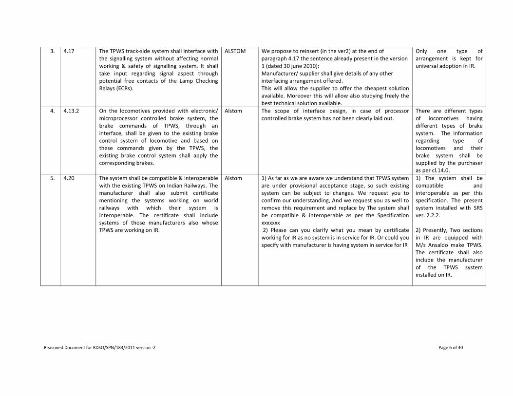
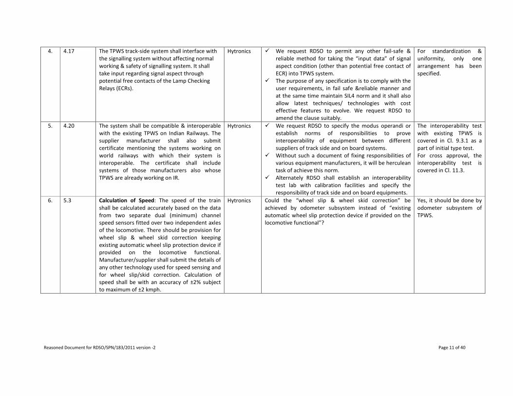
3. 4.17 The TPWS track-side system shall interface with
the signalling system without affecting normal
working & safety of signalling system. It shall
take input regarding signal aspect through
potential free contacts of the Lamp Checking
Relays (ECRs).
ALSTOM We propose to reinsert (in the ver2) at the end of
paragraph 4.17 the sentence already present in the version
1 (dated 30 june 2010):
Manufacturer/ supplier shall give details of any other
interfacing arrangement offered.
This will allow the supplier to offer the cheapest solution
available. Moreover this will allow also studying freely the
best technical solution available.
Only one type of
arrangement is kept for
universal adoption in IR.
4. 4.13.2 On the locomotives provided with electronic/
microprocessor controlled brake system, the
brake commands of TPWS, through an
interface, shall be given to the existing brake
control system of locomotive and based on
these commands given by the TPWS, the
existing brake control system shall apply the
corresponding brakes.
Alstom The scope of interface design, in case of processor
controlled brake system has not been clearly laid out.
There are different types
of locomotives having
different types of brake
system. The information
regarding type of
locomotives and their
brake system shall be
supplied by the purchaser
as per cl.14.0.
5. 4.20 The system shall be compatible & interoperable
with the existing TPWS on Indian Railways. The
manufacturer shall also submit certificate
mentioning the systems working on world
railways with which their system is
interoperable. The certificate shall include
systems of those manufacturers also whose
TPWS are working on IR.
Alstom 1) As far as we are aware we understand that TPWS system
are under provisional acceptance stage, so such existing
system can be subject to changes. We request you to
confirm our understanding, And we request you as well to
remove this requirement and replace by The system shall
be compatible & interoperable as per the Specification
xxxxxxx
2) Please can you clarify what you mean by certificate
working for IR as no system is in service for IR. Or could you
specify with manufacturer is having system in service for IR
1) The system shall be
compatible and
interoperable as per this
specification. The present
system installed with SRS
ver. 2.2.2.
2) Presently, Two sections
in IR are equipped with
M/s Ansaldo make TPWS.
The certificate shall also
include the manufacturer
of the TPWS system
installed on IR.

Reasoned Document for RDSO/SPN/183/2011 version -2 Page 7 of 40
6. 5.3 Calculation of Speed: The speed of the train
shall be calculated accurately based on the data
from two separate dual (minimum) channel
speed sensors fitted over two independent
axles of the locomotive. There should be
provision for wheel slip & wheel skid correction
keeping existing automatic wheel slip
protection device if provided on the locomotive
functional. Manufacturer/supplier shall submit
the details of any other technology used for
speed sensing and for wheel slip/skid
correction. Calculation of speed shall be with an
accuracy of ±2% subject to maximum of ±2
kmph.
Alstom We would like to highlight that speed calculation is an
estimated and thsi is teh reason to have tolerance.
Therefore we request you to replace Calculation of speed
shall be with an accuracy of +-2% subject to maximum of +-
2kmph" with "Calculation of extimated speed shall be with
an accuracy of +-2% subject to maximum of +-2kmph".
It is already defined that
accuracy of calculated
speed is ±2% subject to
maximum of ±2kmph.
7. 5.8.1 TPWS shall continuously compare the current
speed of train with the permitted speed at all
locations in all those modes in which speed
monitoring is available except for release speed
monitoring. A warning must be given to the
driver to enable him to react and avoid
intervention from TPWS before the application
of service brake. The following actions shall be
taken by TPWS depending upon the difference
in current train speed & permitted speed:
Alstom These requirements are not compliant with ETCS standard.
Any change in versus Unisig will impact the globaly teh
system which could lead to serious impact and will
moreover affect the interoperability. We kindly request
you to specify instead of your existing requirements that it
shall be "According to Unisig Subset-026-3.
The clause modified
suitably. Any deviation
may be mentioned
specifically.
Reasoned Document for RDSO/SPN/183/2011 version -2 Page 8 of 40
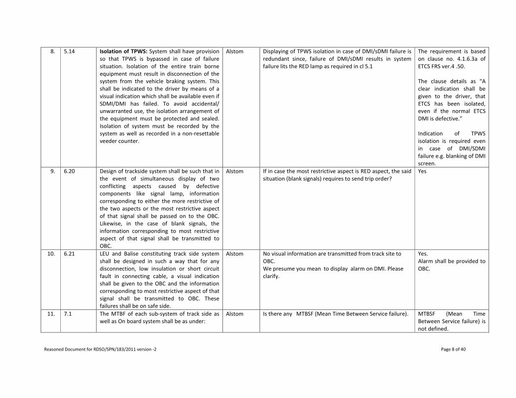
8. 5.14 Isolation of TPWS: System shall have provision
so that TPWS is bypassed in case of failure
situation. Isolation of the entire train borne
equipment must result in disconnection of the
system from the vehicle braking system. This
shall be indicated to the driver by means of a
visual indication which shall be available even if
SDMI/DMI has failed. To avoid accidental/
unwarranted use, the isolation arrangement of
the equipment must be protected and sealed.
Isolation of system must be recorded by the
system as well as recorded in a non-resettable
veeder counter.
Alstom Displaying of TPWS isolation in case of DMI/sDMI failure is
redundant since, failure of DMI/sDMI results in system
failure lits the RED lamp as required in cl 5.1
The requirement is based
on clause no. 4.1.6.3a of
ETCS FRS ver.4 .50.
The clause details as “A
clear indication shall be
given to the driver, that
ETCS has been isolated,
even if the normal ETCS
DMI is defective.”
Indication of TPWS
isolation is required even
in case of DMI/SDMI
failure e.g. blanking of DMI
screen.
9. 6.20 Design of trackside system shall be such that in
the event of simultaneous display of two
conflicting aspects caused by defective
components like signal lamp, information
corresponding to either the more restrictive of
the two aspects or the most restrictive aspect
of that signal shall be passed on to the OBC.
Likewise, in the case of blank signals, the
information corresponding to most restrictive
aspect of that signal shall be transmitted to
OBC.
Alstom If in case the most restrictive aspect is RED aspect, the said
situation (blank signals) requires to send trip order?
Yes
10. 6.21 LEU and Balise constituting track side system
shall be designed in such a way that for any
disconnection, low insulation or short circuit
fault in connecting cable, a visual indication
shall be given to the OBC and the information
corresponding to most restrictive aspect of that
signal shall be transmitted to OBC. These
failures shall be on safe side.
Alstom No visual information are transmitted from track site to
OBC.
We presume you mean to display alarm on DMI. Please
clarify.
Yes.
Alarm shall be provided to
OBC.
11. 7.1 The MTBF of each sub-system of track side as
well as On board system shall be as under:
Alstom Is there any MTBSF (Mean Time Between Service failure).
MTBSF (Mean Time
Between Service failure) is
not defined.
Reasoned Document for RDSO/SPN/183/2011 version -2 Page 9 of 40
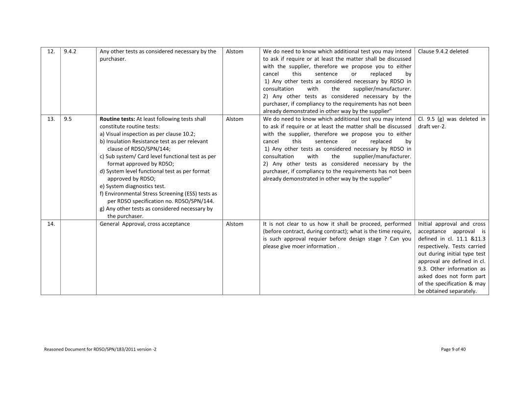
12. 9.4.2 Any other tests as considered necessary by the
purchaser.
Alstom We do need to know which additional test you may intend
to ask if require or at least the matter shall be discussed
with the supplier, therefore we propose you to either
cancel this sentence or replaced by
1) Any other tests as considered necessary by RDSO in
consultation with the supplier/manufacturer.
2) Any other tests as considered necessary by the
purchaser, if compliancy to the requirements has not been
already demonstrated in other way by the supplier"
Clause 9.4.2 deleted
13. 9.5 Routine tests: At least following tests shall
constitute routine tests:
a) Visual inspection as per clause 10.2;
b) Insulation Resistance test as per relevant
clause of RDSO/SPN/144;
c) Sub system/ Card level functional test as per
format approved by RDSO;
d) System level functional test as per format
approved by RDSO;
e) System diagnostics test.
f) Environmental Stress Screening (ESS) tests as
per RDSO specification no. RDSO/SPN/144.
g) Any other tests as considered necessary by
the purchaser.
Alstom We do need to know which additional test you may intend
to ask if require or at least the matter shall be discussed
with the supplier, therefore we propose you to either
cancel this sentence or replaced by
1) Any other tests as considered necessary by RDSO in
consultation with the supplier/manufacturer.
2) Any other tests as considered necessary by the
purchaser, if compliancy to the requirements has not been
already demonstrated in other way by the supplier"
Cl. 9.5 (g) was deleted in
draft ver-2.
14. General Approval, cross acceptance Alstom It is not clear to us how it shall be proceed, performed
(before contract, during contract); what is the time require,
is such approval requier before design stage ? Can you
please give moer information .
Initial approval and cross
acceptance approval is
defined in cl. 11.1 &11.3
respectively. Tests carried
out during initial type test
approval are defined in cl.
9.3. Other information as
asked does not form part
of the specification & may
be obtained separately.

Reasoned Document for RDSO/SPN/183/2011 version -2 Page 10 of 40
RDSO’s remarks on comments received on Draft TPWS specification RDSO/SPN/183/2010 ver -2 (dt. 03-09-2010)
SN Clause No. Clause Details Comments
from
Comment & Suggestion RDSO’s remarks
1. 4.1(ii)(b) Juridical Recorder Unit (JRU) for data logging for
diagnostics & investigation.
Hytronics � As per specification Juridical Recorder Unit (JRU) is for
(a)data logging & (b)diagnostics activities.
� We request RDSO to include detailed requirements
vis-à-vis Indian Railway Requirement/s i.e. parameters
required to be monitored, displayed and user
interface details for (a) Data logging & (b) Diagnostics.
The parameters to be
logged and diagnostics
are further covered in Cl.
5.16.
2. 4.1(ii)(j) System Isolating Unit (Both Electrical &
Mechanical)
Hytronics How do you exactly define “System Isolating Unit”? We
request RDSO to specify the requirements for this same
Meaning of isolation is
further covered in Cl.
5.14
3. 4.7 TPWS shall be capable of being correctly &
effectively interfaced to existing
Air/Vacuum/Dual/Electro-pneumatic brake
system of Diesel and Electric Locomotives as well
as other self propelled vehicles treated as train.
Hytronics � We request RDSO to include specifications of existing
Air/Vacuum/Dual/Electro-pneumatic brake system of
Diesel and Electric Locomotives as well as other self
propelled vehicles treated as train, vide different
annexures to the main specifications.
� This will facilitate the manufacturer of TPWS
equipment to develop the correct technology and
most efficient technology, suitable and complying
with the brake interface and characteristics, without
running from pillar to post to obtain the necessary
technical details, which may or may not be authentic
information.
� The most vital & important activity of TPWS
equipment is braking and brake interface. Hence it is
very much appropriate to include the Brake interface
and brake characteristics by RDSO, who is the
principal authority to approve, validate & accept the
TPWS equipment.
Type of brake interface
based on type of
locomotives is further
covered in Cl. 5.13 and Cl.
11.6.1. The type of
locomotive & existing
brake system will be
specified by the user as in
Cl. 14.0
Reasoned Document for RDSO/SPN/183/2011 version -2 Page 11 of 40
4. 4.17 The TPWS track-side system shall interface with
the signalling system without affecting normal
working & safety of signalling system. It shall
take input regarding signal aspect through
potential free contacts of the Lamp Checking
Relays (ECRs).
Hytronics � We request RDSO to permit any other fail-safe &
reliable method for taking the “input data” of signal
aspect condition (other than potential free contact of
ECR) into TPWS system.
� The purpose of any specification is to comply with the
user requirements, in fail safe &reliable manner and
at the same time maintain SIL4 norm and it shall also
allow latest techniques/ technologies with cost
effective features to evolve. We request RDSO to
amend the clause suitably.
For standardization &
uniformity, only one
arrangement has been
specified.
5. 4.20 The system shall be compatible & interoperable
with the existing TPWS on Indian Railways. The
supplier manufacturer shall also submit
certificate mentioning the systems working on
world railways with which their system is
interoperable. The certificate shall include
systems of those manufacturers also whose
TPWS are already working on IR.
Hytronics � We request RDSO to specify the modus operandi or
establish norms of responsibilities to prove
interoperability of equipment between different
suppliers of track side and on board systems.
� Without such a document of fixing responsibilities of
various equipment manufacturers, it will be herculean
task of achieve this norm.
� Alternately RDSO shall establish an interoperability
test lab with calibration facilities and specify the
responsibility of track side and on board equipments.
The interoperability test
with existing TPWS is
covered in Cl. 9.3.1 as a
part of initial type test.
For cross approval, the
interoperability test is
covered in Cl. 11.3.
6. 5.3 Calculation of Speed: The speed of the train
shall be calculated accurately based on the data
from two separate dual (minimum) channel
speed sensors fitted over two independent axles
of the locomotive. There should be provision for
wheel slip & wheel skid correction keeping
existing automatic wheel slip protection device if
provided on the locomotive functional.
Manufacturer/supplier shall submit the details of
any other technology used for speed sensing and
for wheel slip/skid correction. Calculation of
speed shall be with an accuracy of ±2% subject
to maximum of ±2 kmph.
Hytronics Could the “wheel slip & wheel skid correction” be
achieved by odometer subsystem instead of “existing
automatic wheel slip protection device if provided on the
locomotive functional”?
Yes, it should be done by
odometer subsystem of
TPWS.
Reasoned Document for RDSO/SPN/183/2011 version -2 Page 12 of 40
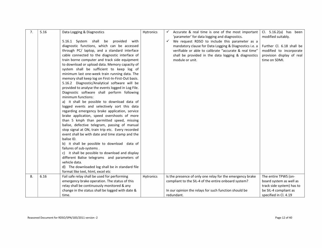
7. 5.16 Data Logging & Diagnostics
5.16.1 System shall be provided with
diagnostic functions, which can be accessed
through PC/ laptop, and a standard interface
cable connected to the diagnostic interface of
train borne computer and track side equipment
to download or upload data. Memory capacity of
system shall be sufficient to keep log of
minimum last one-week train running data. The
memory shall keep log on First-In-First-Out basis.
5.16.2 Diagnostic/Analytical software will be
provided to analyse the events logged in Log File.
Diagnostic software shall perform following
minimum functions:
a) it shall be possible to download data of
logged events and selectively sort this data
regarding emergency brake application, service
brake application, speed overshoots of more
than 5 kmph than permitted speed, missing
balise, defective telegram, passing of manual
stop signal at ON, train trip etc. Every recorded
event shall be with date and time stamp and the
balise ID.
b) it shall be possible to download data of
failures of sub-systems .
c) it shall be possible to download and display
different Balise telegrams and parameters of
vehicle data.
d) The downloaded log shall be in standard file
format like text, html, excel etc
Hytronics � Accurate & real time is one of the most important
‘parameter’ for data logging and diagnostics.
� We request RDSO to include this parameter as a
mandatory clause for Data Logging & Diagnostics i.e. a
verifiable or able to calibrate “accurate & real time”
shall be provided in the data logging & diagnostics
module or unit.
Cl. 5.16.2(a) has been
modified suitably.
Further Cl. 6.18 shall be
modified to incorporate
provision display of real
time on SDMI.
8. 6.16 Fail safe relay shall be used for performing
emergency brake operation. The status of this
relay shall be continuously monitored & any
change in the status shall be logged with date &
time.
Hytronics Is the presence of only one relay for the emergency brake
compliant to the SIL-4 of the entire onboard system?
In our opinion the relays for such function should be
redundant.
The entire TPWS (on-
board system as well as
track side system) has to
be SIL-4 compliant as
specified in Cl. 4.19
Reasoned Document for RDSO/SPN/183/2011 version -2 Page 13 of 40
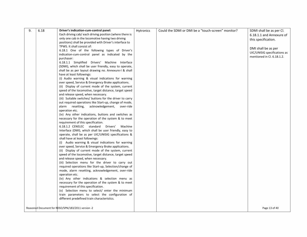
9. 6.18 Driver’s indication-cum-control panel:
Each driving cab/ each driving position (where there is
only one cab in the locomotive having two driving
positions) shall be provided with Driver’s interface to
TPWS. It shall consist of:
6.18.1 One of the following types of Driver’s
indication-cum-control panel as indicated by the
purchaser:
6.18.1.1 Simplified Drivers’ Machine Interface
(SDMI), which shall be user friendly, easy to operate,
shall be as per layout drawing no. Annexure-I & shall
have at least followings:
(i) Audio warning & visual indications for warning
over speed, Service & Emergency Brake applications.
(ii) Display of current mode of the system, current
speed of the locomotive, target distance, target speed
and release speed, when necessary.
(iii) Suitable switches/ buttons for the driver to carry
out required operations like Start-up, change of mode,
alarm resetting, acknowledgement, over-ride
operation etc.
(iv) Any other indications, buttons and switches as
necessary for the operation of the system & to meet
requirement of this specification.
6.18.1.2 CENELEC standard Drivers’ Machine
Interface (DMI), which shall be user friendly, easy to
operate, shall be as per UIC/UNISIG specifications &
shall have at least followings:
(i) Audio warning & visual indications for warning
over speed, Service & Emergency Brake applications.
(ii) Display of current mode of the system, current
speed of the locomotive, target distance, target speed
and release speed, when necessary.
(iii) Selection menu for the driver to carry out
required operations like Start-up, Selection/change of
mode, alarm resetting, acknowledgement, over-ride
operation etc.
(iv) Any other indications & selection menu as
necessary for the operation of the system & to meet
requirement of this specification.
(v) Selection menu to select/ enter the minimum
train parameters to select the configuration of
different predefined train characteristics.
Hytronics Could the SDMI or DMI be a “touch-screen” monitor? SDMI shall be as per Cl.
6.18.1.1 and Annexure of
this specification.
DMI shall be as per
UIC/UNISIG specifications as
mentioned in Cl. 6.18.1.2.

Reasoned Document for RDSO/SPN/183/2011 version -2 Page 14 of 40
10. 7.7 Manufacturer shall guarantee availability of
spares throughout the life of the equipments
Hytronics We request RDSO to specify the Time period for
availability of spares, as it is a very important commercial
requirement.
The manufacturer shall
specify the expected life
of equipment as
mentioned in Cl. 11.5
11. Not
applicable
Language of the equipments/tool Hytronics Which is the language for the equipments (i.e. DMI) and
tools?
English as mentioned in
the drawing of SDMI.
12. - - - - - - HBL Currently TPWS only prevents Signal Passing At Danger
(SPAD). TPWS is reliant on the signaling system for
prevention of SPAD. In case of failure of the signaling
system, TPWS would not be in a position to prevent
collisions if two trains are found to be on the same track.
Provision to be made in the TPWS specification for
prevention of collisions in case of failure of signaling
system.
Cl. 1.2 may be referred
for the purpose of TPWS.
Other features are not
considered as part of
TPWS at present.
13. - - - - - - HBL TPWS cannot work reliably in Automatic Block Sections of
the Railway network. In an Automatic Block Section the
locomotive pilot has an authority to proceed in a restricted
speed even if the signal ahead indicates RED aspect. Any
human error when exercising these discretionary powers
vested in the locomotive pilot might lead to collisions.
TPWS specification to include provisions to prevent
collisions incase of human error in Auto-Block sections.
This is covered in Cl. 5.11
14. - - - - - - HBL TPWS should have comprehensive collision prevention
features over and above SPAD.
Cl. 1.2 may be referred
for the purpose of TPWS.
Other features are not
considered as part of
TPWS at present.

Reasoned Document for RDSO/SPN/183/2011 version -2 Page 15 of 40
15. - - - - - - HBL TPWS specification requires each of the sub-systems
constituting TPWS should be interoperable with makes of
other vendors. TPWS uses LEU and Balise for passing the
“Movement Authority” information to the on-board
system. LEU and Balise are expensive equipment and
constitute to significant cost of the overall TPWS. If the
LEU and Balise specifications are issued by RDSO with
interface requirements clearly defined for the following:
a. LEU and Balise
b. Balise and On-board system
Low cost indigenous LEU and Balise with the same Safety
Integrity Levels and interoperable with the existing TPWS
sub-systems can be built, thereby reducing the cost of the
system significantly.
The interface
requirements are as per
ETCS/ERTMS
specifications as specified
in Cl. 2.1 & 4.1.
16. MOM
dt
20.10.2010
Modification in the target distance bar to show target
distance upto 1500m in place of 1000m at present.
The target distance bar
with 1500m is shown in
the drawing.
17. MOM
dt
20.10.2010
For audio alarms, volume control shall be provided with
fixed minimum level so that alarm is audible even at
minimum setting of volume control.
Cl.6.18 may be modified
suitably.
18. MOM
dt
20.10.2010
Provision for display of date and time alongwith
arrangement for setting the clock is required on SDMI so
that the events logged in EVC are recorded with correct
date and time.
Cl.6.18 has been
modified. Provision of
real time & date has been
made in OBC/ JRU in Cl.
5.16.2(a). Therefore, only
display of date & time is
incorporated. Provision of
setting of time from SDMI
not considered as Driver
is not supposed to modify
the time set in OBC/JRU. .
19. MOM
dt
20.10.2010
The five types of alarms are basically information to the
loco pilot and are different. However, display of contextual
information alongwith alarm and otherwise is
recommended on SDMI.
Cl.6.18 may be modified
suitably.

Reasoned Document for RDSO/SPN/183/2011 version -2 Page 16 of 40
Remarks on Draft TPWS specification RDSO/SPN/183/2010 ver -2 (dt. 24-12-2010)
SN Clause No. Clause Details Comments
from
Comment & Suggestion RDSO’s remarks
1. ----- ----- PS & EMU Simulated test for functioning of the TPWS with
traction system brake system needs to be included.
Included in STR.
2. ----- ----- PS & EMU The interface protocol for interface with the
existing software control traction and brake system
to be spelt out.
The interface is not through
software & therefore, no
interface protocol is
required.
3. ----- ----- PS & EMU Clause for field trial to be included. While granting the type
approval, the field trial is
given as per ISO procedure.
4. 6.6 The on board as well track side systems of TPWS shall
be immune to following interference currents
generated by locomotive/EMU etc.
SN Interference Current Overal
l Limit
1. Psophometric current AC
traction
10.0A
2. Psophometric current DC
traction
2.0A
3. DC Component in AC mode 4.7A
4. Second Harmonic
Component(100 Hz) in AC
traction
3.0A
5. 1400Hz to 5000 Hz 400mA
6. More than 5000Hz upto
50000 Hz
270mA
7. 50 Hz component in DC
mode
2.4A
PS & EMU In clause no. 6.6, the value of second harmonic
component (100 Hz) in AC traction to be changed to
8.5A as confirmed by you.
Agreed.
5. ----- ----- PS & EMU Since lots of Relays/ contactors are installed in
EMUs, the energy stored in the coil of relays/
contactors may cause EMI/EMC interference. The
manufacturer shall acquaint themselves with the
control system of EMUs and may carry out the
Cl. 6.9 modified to cover the
requirement.
Reasoned Document for RDSO/SPN/183/2011 version -2 Page 17 of 40
EMI/EMC measurement before finalizing the
scheme for EMUs.
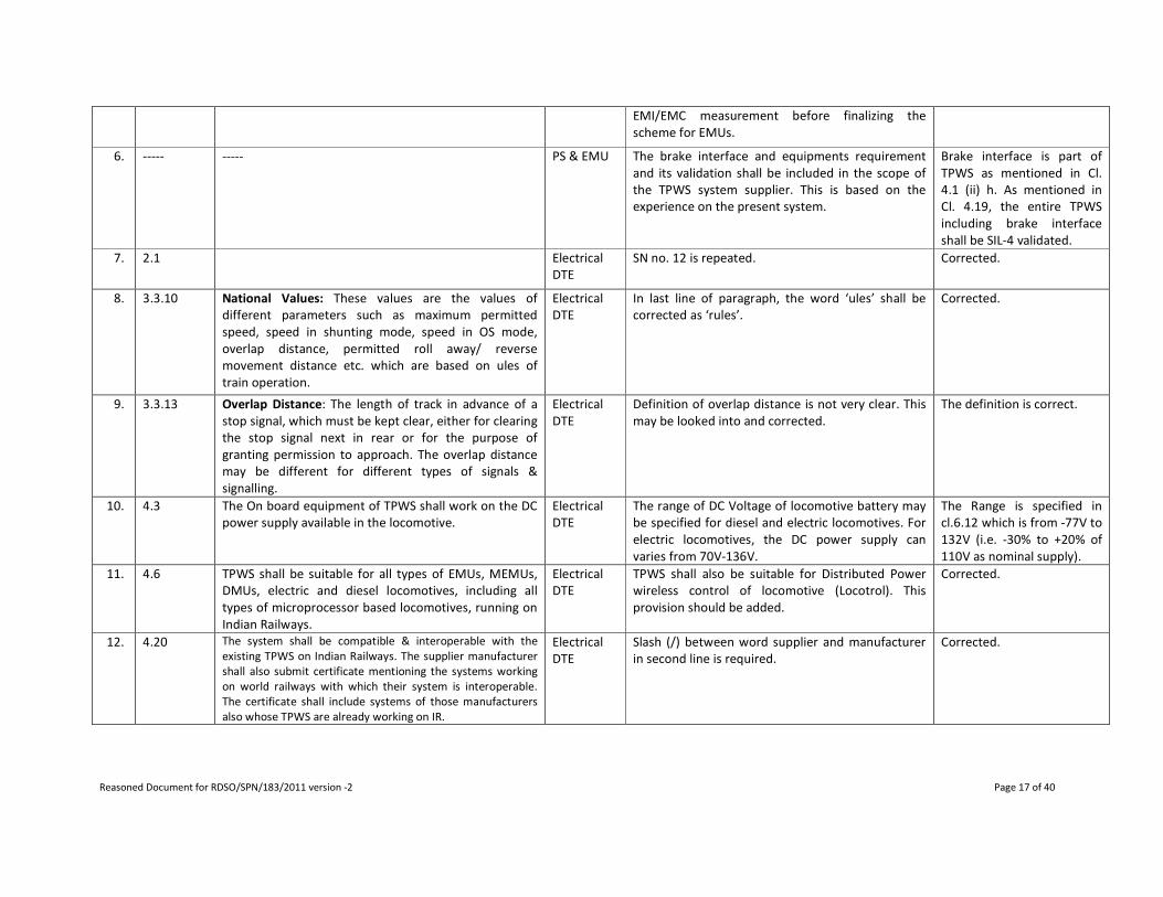
6. ----- ----- PS & EMU The brake interface and equipments requirement
and its validation shall be included in the scope of
the TPWS system supplier. This is based on the
experience on the present system.
Brake interface is part of
TPWS as mentioned in Cl.
4.1 (ii) h. As mentioned in
Cl. 4.19, the entire TPWS
including brake interface
shall be SIL-4 validated.
7. 2.1 Electrical
DTE
SN no. 12 is repeated. Corrected.
8. 3.3.10 National Values: These values are the values of
different parameters such as maximum permitted
speed, speed in shunting mode, speed in OS mode,
overlap distance, permitted roll away/ reverse
movement distance etc. which are based on ules of
train operation.
Electrical
DTE
In last line of paragraph, the word ‘ules’ shall be
corrected as ‘rules’.
Corrected.
9. 3.3.13 Overlap Distance: The length of track in advance of a
stop signal, which must be kept clear, either for clearing
the stop signal next in rear or for the purpose of
granting permission to approach. The overlap distance
may be different for different types of signals &
signalling.
Electrical
DTE
Definition of overlap distance is not very clear. This
may be looked into and corrected.
The definition is correct.
10. 4.3 The On board equipment of TPWS shall work on the DC
power supply available in the locomotive.
Electrical
DTE
The range of DC Voltage of locomotive battery may
be specified for diesel and electric locomotives. For
electric locomotives, the DC power supply can
varies from 70V-136V.
The Range is specified in
cl.6.12 which is from -77V to
132V (i.e. -30% to +20% of
110V as nominal supply).
11. 4.6 TPWS shall be suitable for all types of EMUs, MEMUs,
DMUs, electric and diesel locomotives, including all
types of microprocessor based locomotives, running on
Indian Railways.
Electrical
DTE
TPWS shall also be suitable for Distributed Power
wireless control of locomotive (Locotrol). This
provision should be added.
Corrected.
12. 4.20 The system shall be compatible & interoperable with the
existing TPWS on Indian Railways. The supplier manufacturer
shall also submit certificate mentioning the systems working
on world railways with which their system is interoperable.
The certificate shall include systems of those manufacturers
also whose TPWS are already working on IR.
Electrical
DTE
Slash (/) between word supplier and manufacturer
in second line is required.
Corrected.

Reasoned Document for RDSO/SPN/183/2011 version -2 Page 18 of 40
13. 4.21 (i) The size of the entire on-board equipment
(excluding SDMI/DMI) which is to be provided
inside locomotive’s machine room shall not be
more than 1350 x 560 x 550 mm (Height x width x
depth). The SDMI/DMI to be provided in Driver’s
cab shall not exceed in size by 360mm x 450mm x
150mm (Height x width x depth).
(ii) Suppliers shall specify the number of sub-systems
in which their On-board system can be split.
Supplier shall also submit sizes of such sub-systems.
Electrical
DTE
The size mentioned in this class cannot be
accommodated in various types of electric locos.
The constraint of space is most severe in WAP4 type
of loco for which the tentatively identified available
space locos has already been advised to signal Dte.
In view of this following rewording of clause is
necessary.
(i) There is severe constraint of space in the
locomotives and therefore the equipment shall be
compact & modular in design with possibility of
distributing it into sub-systems to facilitate its
accommodation in the locomotive.
(ii) The space tentatively identified for TPWS is to
the tune of 500DX550WX750H mm &
300DX500WX800H mm in two separate portions.
However, the supplier is advised to make a visit to
any loco shed under advice to RDSO to have an first
hand idea of space availability in WAP4 locomotive,
where the constraint is most severe.
(iii) The supplier shall specify the number of sub-
systems in which their On-Board system can be split.
The supplier shall also submit the sizes of such sub-
systems.
(iv) Due to space constraint, mounting of complete
system or one or more of its sub-systems under-
slung on locomotive frame can also be considered.
Supplier shall specify which of their sub-systems are
suitable for under-slung mounting.
(v) It shall be the responsibility of
supplier/manufacturer to identify space in the
locomotive for installation of on-board equipment
of TPWS. The installation of on-board equipment of
TPWS in space so identified shall not adversely
affect the access to the loco equipments for
maintenance/operation purpose. The supplier
/manufacturer shall obtain RDSO approval for space
so identified for fitment of on-board equipment of
TPWS prior to manufacture/supply.
(i) Agreed
(ii) This need not be
mentioned in the spec.
The max size of TPWS is
covered in cl.4.21(i).
Further availability of space
is covered in next para.
(iii) Covered in cl 4.21(ii)
(iv)This aspect is already
covered in (i) & (v) of the
comment.
(v) Agreed

Reasoned Document for RDSO/SPN/183/2011 version -2 Page 19 of 40
14. 4.23 The on board system shall be upgradeable to ETCS/
ERTMS level-2 with additional hardware & changes in
the software. The supplier to give details of such
additional hardware & changes in the software.
Electrical
DTE
Rewording of clause as under is suggested.
“The on board system shall be upgradeable to ETCS/
ERTMS level-2 with minimal addition of hardware &
changes in the software. The supplier shall give
details of such additional hardware & changes in
the software.”
Minimum can not be
quantified, hence not
included. The next line is
corrected.
15. 5.1 Healthy condition of system: A steady lit green light
indicating that TPWS is in working condition shall be
available in the cab or on the driver’s indication -cum -
control panel. This TPWS healthy indication light shall
extinguish when any fault is detected by TPWS and
immediately “TPWS faulty” red light shall be lit and
audible alarm shall sound to attract attention of driver
(which shall stop on acknowledgement by the driver). In
such case, Emergency brake shall be applied by the
TPWS and the train shall be able to move only after the
TPWS is isolated. However, the “TPWS faulty” red light
shall remain lit till such time fault persists.
Electrical
DTE
As soon as TPWS becomes faulty, it ceases to
monitor the over-speeding by loco pilot. Once the
loco-pilot acknowledges the TPWS faulty condition,
why should there be need for applying emergency
brake and stops the train for isolating the TPWS.
This will result in unnecessary detention. In TPWS
faulty condition, if the driver acknowledges the
fault, its isolation in running condition should be
possible. Clause shall be reviewed accordingly.
Due to fail safety, EB
application will be there.
However, if isolation is
performed during EB
application, then brake shall
be released & Driver can
pickup speed.
16. 5.3 Calculation of Speed: The speed of the train shall be
calculated accurately based on the data from two
separate dual (minimum) channel speed sensors fitted
over two independent axles of the locomotive. There
should be provision for wheel slip & wheel skid
correction keeping existing automatic wheel slip
protection device if provided on the locomotive
functional. Manufacturer/supplier shall submit the
details of any other technology used for speed sensing
and for wheel slip/skid correction. Calculation of speed
shall be with an accuracy of ±2% subject to maximum of
±2 kmph.
Electrical
DTE
It seems that provision of separate dual channel
speed sensors fitted on two independent axles of
locomotive has been kept considering the
arrangement followed by M/s Ansaldo. Meaning of
‘dual channel’ is not clear and can be interpreted
differently by different vendors. Moreover, M/s
Ansaldo could not furnish so far any international
spec/guidelines in support of speed sensing
methodology adopted by them. In view of above,
rewording of clause as under is suggested.
“The system shall incorporate the necessary
hardware and software module for accurate
calculation of the train speed duly accounting for
wheel slip/skid corrections. Manufacturer shall
submit the details of the speed calculation module
along with the supporting international
standards/practices being followed world over for
same. Calculation of speed shall be with an accuracy
of ±2% subject to maximum of ±2 kmph. Further,
the variation in wheel diameter due to normal wear
during time period between two loco maintenance
Corrected.
Reasoned Document for RDSO/SPN/183/2011 version -2 Page 20 of 40
schedules shall not affect accuracy beyond the limits
specified above.”
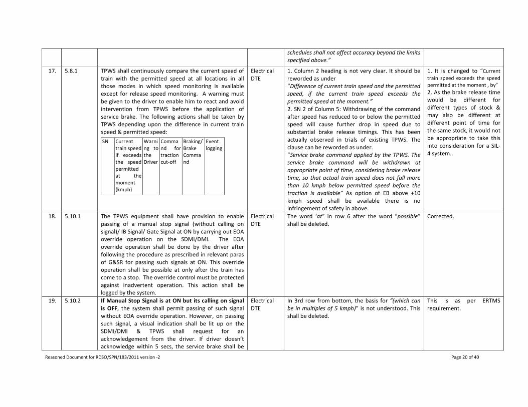
17. 5.8.1 TPWS shall continuously compare the current speed of
train with the permitted speed at all locations in all
those modes in which speed monitoring is available
except for release speed monitoring. A warning must
be given to the driver to enable him to react and avoid
intervention from TPWS before the application of
service brake. The following actions shall be taken by
TPWS depending upon the difference in current train
speed & permitted speed:
SN Current
train speed
if exceeds
the speed
permitted
at the
moment
(kmph)
Warni
ng to
the
Driver
Comma
nd for
traction
cut-off
Braking/
Brake
Comma
nd
Event
logging
Electrical
DTE
1. Column 2 heading is not very clear. It should be
reworded as under
“Difference of current train speed and the permitted
speed, if the current train speed exceeds the
permitted speed at the moment.”
2. SN 2 of Column 5: Withdrawing of the command
after speed has reduced to or below the permitted
speed will cause further drop in speed due to
substantial brake release timings. This has been
actually observed in trials of existing TPWS. The
clause can be reworded as under.
“Service brake command applied by the TPWS. The
service brake command will be withdrawn at
appropriate point of time, considering brake release
time, so that actual train speed does not fall more
than 10 kmph below permitted speed before the
traction is available” As option of EB above +10
kmph speed shall be available there is no
infringement of safety in above.
1. It is changed to “Current
train speed exceeds the speed
permitted at the moment , by”
2. As the brake release time
would be different for
different types of stock &
may also be different at
different point of time for
the same stock, it would not
be appropriate to take this
into consideration for a SIL-
4 system.
18. 5.10.1 The TPWS equipment shall have provision to enable
passing of a manual stop signal (without calling on
signal)/ IB Signal/ Gate Signal at ON by carrying out EOA
override operation on the SDMI/DMI. The EOA
override operation shall be done by the driver after
following the procedure as prescribed in relevant paras
of G&SR for passing such signals at ON. This override
operation shall be possible at only after the train has
come to a stop. The override control must be protected
against inadvertent operation. This action shall be
logged by the system.
Electrical
DTE
The word ‘at” in row 6 after the word “possible”
shall be deleted.
Corrected.
19. 5.10.2 If Manual Stop Signal is at ON but its calling on signal
is OFF, the system shall permit passing of such signal
without EOA override operation. However, on passing
such signal, a visual indication shall be lit up on the
SDMI/DMI & TPWS shall request for an
acknowledgement from the driver. If driver doesn’t
acknowledge within 5 secs, the service brake shall be
Electrical
DTE
In 3rd row from bottom, the basis for “(which can
be in multiples of 5 kmph)” is not understood. This
shall be deleted.
This is as per ERTMS
requirement.

Reasoned Document for RDSO/SPN/183/2011 version -2 Page 21 of 40
applied till driver acknowledges. However, if while
passing such signal, the speed of the train is more than
the speed configured in the system to be followed after
passing such signal then brake shall be immediately
applied to bring the speed to the restricted speed
configured in the system, without waiting for driver’s
acknowledgement. The indication shall remain lit up
until the train passes the switchable/ signal balise (not
the in-fill balise) connected to next signal ahead. This
indication reminds the driver that he should proceed
ahead cautiously at the specified restricted speed as
per G&SR. The driver shall pass such signals at ON after
following the procedure as prescribed in relevant paras
of G&SR & follow the restricted speed as defined in
G&SR. In case the train speed exceeds the restricted
speed configured in the system, TPWS shall take action
as described in para 0 above. Provision should be made
in the system to enable changes in the configured
restricted speed limit to any value (which can be in
multiples of 5 KMPH) at a later date to comply with the
changes in Operating Rules of the Indian Railways.
20. 5.12 Balise Tracking / Balise Linking: The TPWS equipment
shall be capable of identifying missing balise and give
suitable visual indication to driver accordingly. This
event shall be logged by the system. The System shall
be capable of taking following actions under such
condition:
(a) Apply service brake to bring the train to a halt;
(b) Apply emergency brakes to bring the train to a halt.
Purchaser shall select one of the actions as mentioned
in (a) & (b) above, to be taken by the system in case of
missing balise.
Electrical
DTE
1. As the driver is not supposed to constantly look
at TPWS’s DMI while driving and therefore
whenever attention of driver is to be attracted, an
audio alarm along with visual indication is
necessary. Thus word “audio
&” shall be added before word “visual” in 2nd line.
2. Last 2 lines shall be reworded as under “The user
shall be able to select one of the actions as
mentioned in (a) &
(b) above, to be taken by the system in case of
missing balise. Necessary interface shall be provided
for such selection by authorized user.
1. Corrected.
2. Such type of action is
chosen by the zonal railway
at the time of installation of
the system.
21. 5.13 Brake application:
5.13.1 The system shall generate service &
emergency brake commands according to the situation
and apply respective brakes of locomotives in one of
the following manners:
5.13.1.1 On the locomotives not provided with
Electrical
DTE
Add clause 5.13.1.3 as under.
5.13.1.3: The provision of brake interface and its
development in association with respective brake
manufacturers shall be in scope of supply of TPWS.
However, in case RDSO has already finalized a brake
interface for a particular class of loco, same shall be
Brake interface is part of
TPWS as mentioned in Cl.
4.1 (ii) h. As mentioned in
Cl. 4.19, the entire TPWS
including brake interface
shall be SIL-4 validated.

Reasoned Document for RDSO/SPN/183/2011 version -2 Page 22 of 40
electronic/ microprocessor controlled brake system, the
brake commands of TPWS shall be interfaced to the
existing brake system of the locomotive either
pneumatically or electrically (like in EMU/ MEMU etc.)
and shall apply the corresponding brakes.
5.13.1.2 On the locomotives provided with electronic/
microprocessor controlled brake system, the brake
commands of TPWS, through an electronic/ electrical
interface, shall be given to the existing brake control
system of locomotive and based on these commands
given by the TPWS, the existing brake control system
shall apply the corresponding brakes.
provided by the manufacturer.
22. 5.13.4 A non-resettable type electro-mechanical counter shall
be provided to record in the form of counter reading,
the instances of application of emergency brake and
this record shall not be affected by interruption of
power supply to the system.
Electrical
DTE
The specification is silent under following condition
of emergency brake application:
In case TPWS system applies EB while approaching
Red signal and the Red signal turns to Green while
approaching and TPWS has captured the Green
aspect then whether it is required to Stop the train.
In such situation brake release should be possible
without waiting to stop the train after
acknowledgement by loco pilot in order to reduce
detention. However, counter must be incremented
for each EB application by system. A new clause for
this scenario shall be included.
Once the movement
authority is updated by
picking up the off aspect of
the signal, EB shall be
released & train can pickup
the speed.
23. 5.15.14 Reversing- In this mode, the driver is permitted to
change the direction of movement of the train and
drive from the same cab. This mode shall be permitted
by trackside.
Electrical
DTE
REVERSING: The sentence “This mode shall be
permitted by Trackside” is not clear. Does it imply
that trackside balise shall not prevent reversing of
loco? Shall it permit reverse movement within two
signals or beyond that also? Clause needs
elaboration.
Normally, the train is not
allowed to be reversed
beyond a certain distance
treating it as Roll Back which
is not permitted. However,
where the reversing is
permitted, that will be
defined by the balises.
24. 5.16.1 System shall be provided with diagnostic functions,
which can be accessed through PC/ laptop, and a
standard interface cable connected to the diagnostic
interface of train borne computer and track side
equipment to download or upload data. Memory
capacity of system shall be sufficient to keep log of
minimum last one-week train running data. The
Electrical
DTE
The period of data log should match with schedule
inspection interval during which the data log shall
be generally downloaded for analysis. The
periodicity of minor schedule inspection is 90 days
for 3-phase locos and 45 days for conventional
locos. Therefore the memory capacity sufficient to
contain data log of minimum last 90 days shall be
As per ERTMS requirement,
the period of storing the
data has been defined as 24
hour data in case of
accident and one week data
for assessing the
performance of driver.

Reasoned Document for RDSO/SPN/183/2011 version -2 Page 23 of 40
memory shall keep log on First-In-First-Out basis. specified.
25. 5.16.2 Diagnostic/Analytical software will be provided to
analyse the events logged in Log File. Diagnostic
software shall perform following minimum functions:
e) it shall be possible to download data of logged
events and selectively sort this data regarding
emergency brake application, service brake
application, speed overshoots of more than 5 kmph
than permitted speed, missing balise, defective
telegram, passing of manual stop signal at ON, train
trip etc. Every recorded event shall be with real date
and time stamp of OBC/ JRU and the balise ID.
f) it shall be possible to download data of failures of
sub-systems .
g) it shall be possible to download and display different
Balise telegrams and parameters of vehicle data.
h) The downloaded log shall be in standard file format
like text, html, excel etc.
Electrical
DTE
New clause (e) shall be added as under.
(e): It shall be possible to identify the failure of line
side equipments by analysis of data log.
The onboard shall log data
as mentioned in Cl. 5.16.2
(a), the missing balise,
defective telegram from the
trackside. It cannot log the
diagnostic data of track side.
26. 6.6 The on board as well track side systems of TPWS shall
be immune to following interference currents
generated by locomotive/EMU etc.
SN Interference Current Overal
l Limit
1. Psophometric current AC
traction
10.0A
2. Psophometric current DC
traction
2.0A
3. DC Component in AC mode 4.7A
4. Second Harmonic
Component(100 Hz) in AC
traction
3.0A
5. 1400Hz to 5000 Hz 400mA
6. More than 5000Hz upto
50000 Hz
270mA
Electrical
DTE
The SN shall be brought in front of heading. Not clear.

Reasoned Document for RDSO/SPN/183/2011 version -2 Page 24 of 40
7. 50 Hz component in DC
mode
2.4A
27. 6.11 The On Board Computer (OBC) shall be capable of being
connected to driver’s SDMI/DMI provided in each cab/
each driving position (where there is only one cab in the
locomotive having two driving positions) of the
locomotive. It shall be interfaced with Driver Control
Switch so that at a time only one SDMI/DMI is active &
other gets locked. On EMU/MEMU/DMU, OBCs with
individual driver’s SDMI/DMI shall be provided in each
of the driving cabs. The train characteristics, wheel
diameter etc. shall be loadable into OBC through the
respective ports on the OBC module using special
software tool.
Electrical
DTE
Provision of RTC in OBC shall be specified. Covered in Cl. 5.16.2(a).
28. 6.15 The system shall facilitate programming of braking
characteristics of the system. It shall be possible to
program on board computer via diagnostic PC for date,
time, wheel diameter, number of impulses per wheel
revolution, emergency braking deceleration rate,
maximum vehicle speed etc.
Electrical
DTE
The clause shall be reworded as under.
“The system shall have facility for entry/setting of
various parameters, required for its functioning, in
on-board computer during initial configuration
through LAPTOP/PC”.
This is modified as:
“It shall be possible to
program various parameters
in on board computer
required for its functioning
via diagnostic PC. The data
for example, may include
date, time, wheel diameter,
number of impulses per
wheel revolution,
emergency braking
deceleration rate, maximum
train speed etc.
29. 6.16 Fail safe relay shall be used for performing emergency
brake operation. The status of this relay shall be
continuously monitored & any change in the status shall
be logged with date & time.
Electrical
DTE
The word “Fail safe relay” should be qualified. The
sentence as under is suggested to be added at the
end.
“Here, Fail safe relay means that the arrangement
will be such that failure of relay or its associated
wiring will be on safer side i.e. system shall
command EB in such failures.”
Corrected.
30. 6.18.1.1 Simplified Drivers’ Machine Interface (SDMI), which
shall be user friendly, easy to operate, shall be as per
layout drawing no. Annexure-I & shall have at least
followings:
Electrical
DTE
As point of intervention for SB/EB depends on train
formation, it is desirable that train formation as
entered in the system is visible on DMI/SDMI so
that any discrepancy in same is noticed by the
Agreed.
Reasoned Document for RDSO/SPN/183/2011 version -2 Page 25 of 40
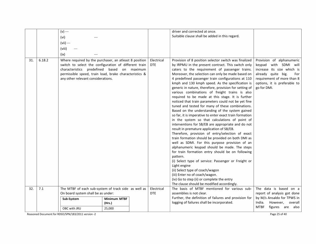
(v) ---
(vi) ---
(vii) ---
(viii) ---
(ix) ---
driver and corrected at once.
Suitable clause shall be added in this regard.
31. 6.18.2 Where required by the purchaser, an atleast 8 position
switch to select the configuration of different train
characteristics predefined based on maximum
permissible speed, train load, brake characteristics &
any other relevant considerations.
Electrical
DTE
Provision of 8 position selector switch was finalized
by IRPMU in the present contract. This switch only
caters to the requirement of passenger trains.
Moreover, the selection can only be made based on
4 predefined passenger train configurations at 110
kmph and 130 kmph speed. As the specification is
generic in nature, therefore, provision for setting of
various combinations of freight trains is also
required to be made at this stage. It is further
noticed that train parameters could not be yet fine
tuned and tested for many of these combinations.
Based on the understanding of the system gained
so far, it is imperative to enter exact train formation
in the system so that calculations of point of
interventions for SB/EB are appropriate and do not
result in premature application of SB/EB.
Therefore, provision of entry/selection of exact
train formation should be provided on both DMI as
well as SDMI. For this purpose provision of an
alphanumeric keypad should be made. The steps
for train formation entry should be on following
pattern.
(i) Select type of service: Passenger or Freight or
Light engine
(ii) Select type of coach/wagon
(iii) Enter no of coach/wagon.
(iv) Go to step (ii) or complete the entry
The clause should be modified accordingly.
Provision of alphanumeric
keypad with SDMI will
increase its size which is
already quite big. For
requirement of more than 8
options, it is preferable to
go for DMI.
32. 7.1 The MTBF of each sub-system of track side as well as
On board system shall be as under:
Sub-System Minimum MTBF
(Hrs.)
OBC with JRU 25,000
Electrical
DTE
The basis of MTBF mentioned for various sub-
assemblies is not clear.
Further, the definition of failures and provision for
logging of failures shall be incorporated.
The data is based on a
report of analysis got done
by M/s Ansaldo for TPWS in
India. However, overall
MTBF figures are also

Reasoned Document for RDSO/SPN/183/2011 version -2 Page 26 of 40
SDMI/DMI 20,000
BTM 25,000
Balise Antenna 1,00,000
Speed & Distance
Measuring Unit
25,000
TIU 15,000
LEU 60,000
Balise 1,00,000
included in the clause.
33. 8.3 Train borne (external) equipment shall have minimum
protection code of IP 67.
Electrical
DTE
The word ‘train borne’ shall be replaced by “on-
board”.
Shall be corrected.
34. 8.5 The design of on board & track side systems shall take
into account switching transients that may occur, in
either the system or out side, of any magnitude, upto
and including interruption due to short circuit of 25 KV
system. The design shall also take into account supply
related supply related surge & transient.
Electrical
DTE
The word “supply related” is repeated. Same shall
be corrected.
Shall be corrected.
35. 9.3.3 For on board system, following tests shall also
constitute type tests:
(a) Performance Test as per clause 10.2.2 of IEC 60571
(b) Cooling Test as per clause 10.2.3 of IEC 60571
(c) Dry heat test as per clause 10.2.4 of IEC 60571
(d) Damp heat test as per clause 10.2.5 of IEC 60571
(e) Supply over voltage, Surges and electrostatic
discharge test as per clause 10.2.6 of IEC 60571
(f) Transient burst susceptibility test as per clause
10.2.7 of IEC 60571
(g) Insulation test as per clause 10.2.9 of IEC 60571
(h) Salt mist test as per clause 10.2.10 of IEC 60571
(i) Vibration and shock test as per IEC 61373
(j) Water tightness test for on board external
components as per clause 10.2.12 of IEC 60571
(k) Tests for reliability of electronics used in rolling stock
as per RDSO specification no. ELRS/SPEC/SI/0015 of
Oct 2001.
Electrical
DTE
Visual Inspection as per Clause no 10.2.1 of IEC
60571 shall be added.
Visual inspection is defined
in cl 10.2 which is
considered better than IEC
clause.

Reasoned Document for RDSO/SPN/183/2011 version -2 Page 27 of 40
36. 11.0 (ii) Verification and validation of safety, reliability &
availability etc. as per relevant standards (SIL 4 or
equivalent) from reputed agency having experience in
this field. The agency to be engaged for validation shall
be got approved from RDSO. The certificate alongwith
proof of safety report or its equivalent safety report or
its equivalent giving complete tests & their results that
have been undertaken by the manufacturer or
independent safety assessor shall also be submitted.
Electrical
DTE
The meaning of following is not clear.
“….The certificate along with proof of safety report
or its equivalent safety report or its equivalent
giving complete tests & their results that have been
undertaken by the manufacturer or independent
safety assessor shall also be
submitted.”
This shall be elaborated for clarity.
Cl. 11.1 (ii): Language
corrected.
37. 11.1 Manufacturer shall furnish following informationat the
time of initial type approval:
Electrical
DTE
the word ‘informationat’ shall be corrected as
‘information at’
Corrected.
38. 11.6.2 The braking algorithm along with input parameter shall
be supplied by the manufacturer/supplier & got
approved from RDSO before its implementation in the
section.
Electrical
DTE
In view of experience of existing system, rewording
of clause as follows is suggested.
“RDSO shall supply the data of weight, rotating
mass, and Braking effort of various types of locos,
coaches and wagons. Values of EBD, SBD and max
acceleration with +- 10% accuracy for different train
formations shall also be supplied by RDSO. The
working out of correct train parameters shall be the
responsibility of the supplier based on this
information. The braking algorithm along with the
input parameter values for various train
configurations shall be furnished & demonstrated to
the satisfaction of RDSO by the
manufacturer/supplier before implementation in
the section.”
Corrected.
39. ---- Electrical
DTE
(i) The option of deciding between SDMI and DMI
has been left to the purchaser. Why such an option
has been kept and how the user will decide is not
clear?
It is for the purchaser to
decide as per requirement.
40. ---- Electrical
DTE
(ii) Suggestions/ comments of Rlys, particularly NR,
NCR & SR, who have experience of the TPWS
system, should also be invited.
The comments of Rlys S&T
deptt. were taken at Signal
Standards Committee (SSC)
meeting. The remarks from
Electrical department of
Railways shall be obtained
by concerned directorate of
RDSO.
Reasoned Document for RDSO/SPN/183/2011 version -2 Page 28 of 40
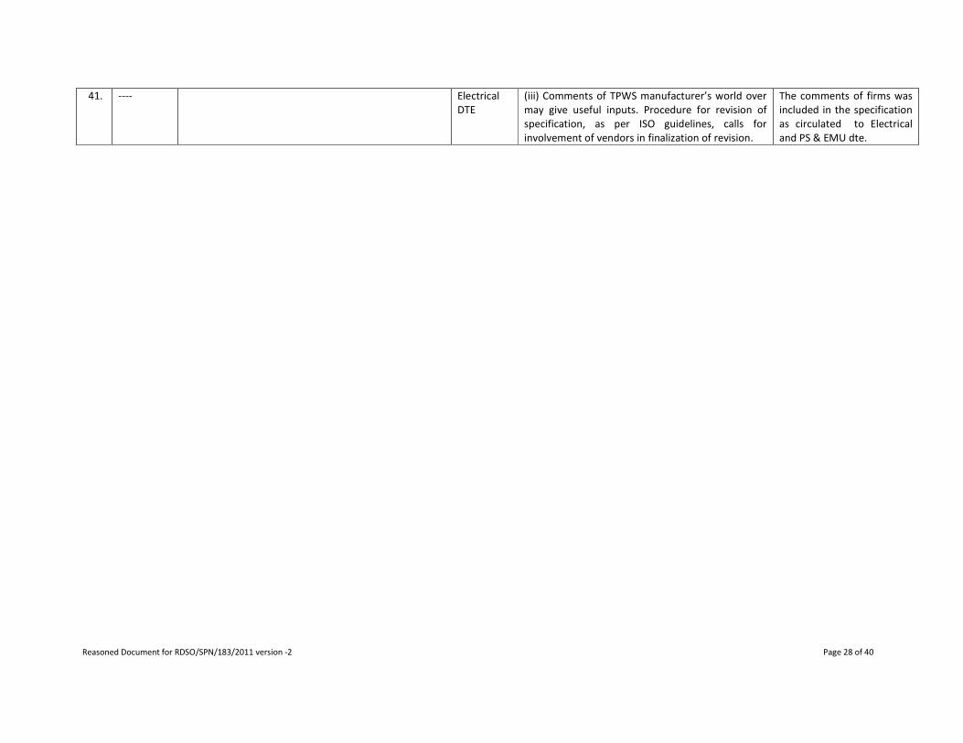
41. ---- Electrical
DTE
(iii) Comments of TPWS manufacturer’s world over
may give useful inputs. Procedure for revision of
specification, as per ISO guidelines, calls for
involvement of vendors in finalization of revision.
The comments of firms was
included in the specification
as circulated to Electrical
and PS & EMU dte.

Reasoned Document for RDSO/SPN/183/2011 version -2 Page 29 of 40
Other changes in draft TPWS specification RDSO/SPN/183/2010 ver -2 (dt. 24-12-2010)
SN Clause No. Clause Details of specification no.
RDSO/SPN/183/2010 Ver.-1
Reason for change Modified clause
1. 5.8.1
Serial no. 3
of table
Current train speed if exceeds the speed
permitted at the moment (kmph): Above 10
kmph
Warning to the Driver: Continuous audio &
visual warnings
Command for traction cut-off: Yes
Braking/ Brake Command: Emergency brake is
applied till the train is brought to a halt. The
emergency brake gets released when train stops.
Event logging: Yes
While controlling the speed, the TPWS
should apply EB to reduce the speed
below permitted speed.
Current train speed if exceeds the speed permitted at the
moment (kmph): Above 10 kmph
Warning to the Driver: Continuous audio & visual warnings
Command for traction cut-off: Yes
Braking/ Brake Command: Emergency brake is applied by
the TPWS. There shall be following two programmable
options for release of emergency brake
(a) When the current train speed is reduced to or below
the permitted speed.
(b) When train comes to a halt.
Purchaser shall program one of the above options as per
requirement
Event logging: Yes
2. 5.13.4 In case of emergency brake application, it shall
not be possible to release brake until the train
stops. In such cases, the brakes can be released
only after the train has stopped. In case of Train
Trip (Clause Error! Reference source not found.),
in addition, acknowledgement from Driver is also
required for releasing the emergency brake. A
non-resettable type electro-mechanical counter
shall be provided to record in the form of
counter reading, the instances of application of
emergency brake and this record shall not be
affected by interruption of power supply to the
system.
Changes made due to above reasons. A non-resettable type electro-mechanical counter shall be
provided to record in the form of counter reading, the
instances of application of emergency brake and this
record shall not be affected by interruption of power
supply to the system.
3. 5.16.2 (a) it shall be possible to download data of logged
events and selectively sort this data regarding
emergency brake application, service brake
application, speed overshoots of more than 5
kmph than permitted speed, missing balise,
defective telegram, passing of manual stop signal
at ON, train trip etc. Every recorded event shall
be with date and time stamp and the balise ID.
Provision of real date & time has made
in OBC/JRU
it shall be possible to download data of logged events and
selectively sort this data regarding emergency brake
application, service brake application, speed overshoots of
more than 5 kmph than permitted speed, missing balise,
defective telegram, passing of manual stop signal at ON,
train trip etc. Every recorded event shall be with real date
and time stamp of OBC/JRU and the balise ID

Reasoned Document for RDSO/SPN/183/2011 version -2 Page 30 of 40
4. 6.20 Line-side Electronic Unit (LEU) shall also conform
to the latest specifications issued by UIC/UNISIG
and shall be suitable to work with Indian
Railways’ Signalling System. LEU shall be
capable of receiving minimum 10 signal inputs. It
shall be capable of delivering minimum four
separate channels so that at least four data
balises may be driven upto 2500m. The
manufacturer/ supplier shall mention the
maximum number of inputs & maximum number
of channels an LEU can handle.
Interconnecting cable alongwith balise
makes the standard interface for the
LEU.
Line-side Electronic Unit (LEU) shall also conform to the
latest specifications issued by UIC/UNISIG and shall be
suitable to work with Indian Railways’ Signalling System.
LEU shall be capable of receiving minimum 10 signal
inputs. It shall be capable of delivering minimum four
separate channels so that at least four data balises may be
driven upto 2500m. The manufacturer/ supplier shall
mention the maximum number of inputs & maximum
number of channels an LEU can handle. Balise controlling
interface cable shall meet the requirement mentioned in
UNISIG specification for balise.
5. 6.27 (New
clause)
For monitoring the health of LEUs. The Manufacturer/ supplier shall submit the health
monitoring scheme of LEUs.
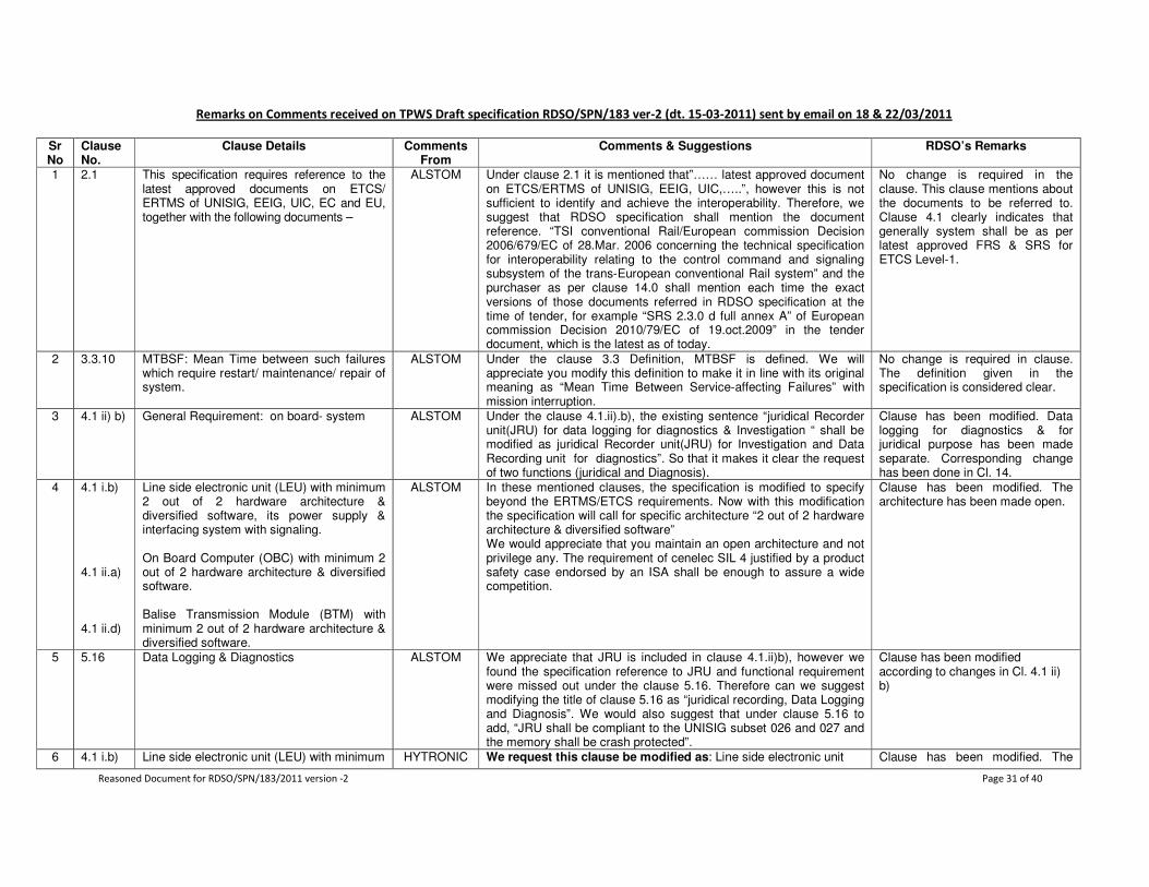
Reasoned Document for RDSO/SPN/183/2011 version -2 Page 31 of 40
Remarks on Comments received on TPWS Draft specification RDSO/SPN/183 ver-2 (dt. 15-03-2011) sent by email on 18 & 22/03/2011
Sr No
Clause No.
Clause Details Comments From
Comments & Suggestions RDSO’s Remarks
1 2.1 This specification requires reference to the latest approved documents on ETCS/ ERTMS of UNISIG, EEIG, UIC, EC and EU, together with the following documents –
ALSTOM Under clause 2.1 it is mentioned that”…… latest approved document on ETCS/ERTMS of UNISIG, EEIG, UIC,…..”, however this is not sufficient to identify and achieve the interoperability. Therefore, we suggest that RDSO specification shall mention the document reference. “TSI conventional Rail/European commission Decision 2006/679/EC of 28.Mar. 2006 concerning the technical specification for interoperability relating to the control command and signaling subsystem of the trans-European conventional Rail system” and the purchaser as per clause 14.0 shall mention each time the exact versions of those documents referred in RDSO specification at the time of tender, for example “SRS 2.3.0 d full annex A” of European commission Decision 2010/79/EC of 19.oct.2009” in the tender document, which is the latest as of today.
No change is required in the clause. This clause mentions about the documents to be referred to. Clause 4.1 clearly indicates that generally system shall be as per latest approved FRS & SRS for ETCS Level-1.
2 3.3.10 MTBSF: Mean Time between such failures which require restart/ maintenance/ repair of system.
ALSTOM Under the clause 3.3 Definition, MTBSF is defined. We will appreciate you modify this definition to make it in line with its original meaning as “Mean Time Between Service-affecting Failures” with mission interruption.
No change is required in clause. The definition given in the specification is considered clear.
3 4.1 ii) b)
General Requirement: on board- system ALSTOM Under the clause 4.1.ii).b), the existing sentence “juridical Recorder unit(JRU) for data logging for diagnostics & Investigation “ shall be modified as juridical Recorder unit(JRU) for Investigation and Data Recording unit for diagnostics”. So that it makes it clear the request of two functions (juridical and Diagnosis).
Clause has been modified. Data logging for diagnostics & for juridical purpose has been made separate. Corresponding change has been done in Cl. 14.
4 4.1 i.b) 4.1 ii.a) 4.1 ii.d)
Line side electronic unit (LEU) with minimum 2 out of 2 hardware architecture & diversified software, its power supply & interfacing system with signaling. On Board Computer (OBC) with minimum 2 out of 2 hardware architecture & diversified software. Balise Transmission Module (BTM) with minimum 2 out of 2 hardware architecture & diversified software.
ALSTOM In these mentioned clauses, the specification is modified to specify beyond the ERTMS/ETCS requirements. Now with this modification the specification will call for specific architecture “2 out of 2 hardware architecture & diversified software” We would appreciate that you maintain an open architecture and not privilege any. The requirement of cenelec SIL 4 justified by a product safety case endorsed by an ISA shall be enough to assure a wide competition.
Clause has been modified. The architecture has been made open.
5 5.16 Data Logging & Diagnostics
ALSTOM We appreciate that JRU is included in clause 4.1.ii)b), however we found the specification reference to JRU and functional requirement were missed out under the clause 5.16. Therefore can we suggest modifying the title of clause 5.16 as “juridical recording, Data Logging and Diagnosis”. We would also suggest that under clause 5.16 to add, “JRU shall be compliant to the UNISIG subset 026 and 027 and the memory shall be crash protected”.
Clause has been modified according to changes in Cl. 4.1 ii) b)
6 4.1 i.b) Line side electronic unit (LEU) with minimum HYTRONIC We request this clause be modified as: Line side electronic unit Clause has been modified. The
Reasoned Document for RDSO/SPN/183/2011 version -2 Page 32 of 40
Sr No
Clause No.
Clause Details Comments From
Comments & Suggestions RDSO’s Remarks
2 out of 2 hardware architecture & diversified software, its power supply & interfacing system with signaling.
S ENTERPRIS
ES
(LEU) with minimum 2 out of 2 hardware architecture & with common or diversified software, its power supply & interfacing system with signaling. Notes: 1. CENELEC specification/permits the use of common software. 2. Clause 7.1b of RDSO/SPN/192/2005 specification for Electronic
Interlocking permits Common software. 3. Clause 7.1(a) of draft spec-EI for BIG Yards-
RDSO/SPN/271/2009 permits common software.
architecture has been made open.
7 4.1 ii.a) On Board Computer (OBC) with minimum 2 out of 2 hardware architecture & diversified software.
HYTRONICS
ENTERPRISES
We request this clause be modified as: Line side electronic unit (LEU) with minimum 2 out of 2 hardware architecture & with common or diversified software, its power supply & interfacing system with signaling. Notes: 1. CENELEC Specifications /permits the use of common software. 2. Clause 7.1b of RDSO/SPN/192/2005 specification for Electronic
Interlocking permits Common software.
Clause has been modified. The architecture has been made open.
8 4.1 ii.d) Balise Transmission Module (BTM) with minimum 2 out of 2 hardware architecture & diversified software.
HYTRONICS
ENTERPRISES
We request this clause be modified as: Notes: 1. CENELEC specification/permits the use of common software. 2. Clause 7.1b of RDSO/SPN/192/2005 specification for Electronic
Interlocking permits Common software. 3. Clause 7.1(a) of draft spec-EI for BIG Yards-
RDSO/SPN/271/2009 permits common software.
Clause has been modified. The architecture has been made open.
9 4.20 The system shall be compatible & interoperable with the existing TPWS on Indian Railways. The supplier/ manufacturer shall also submit certificate mentioning the systems working on world railways with which their system is interoperable. The certificate shall include systems of those manufacturers also whose TPWS are already working on IR.
HYTRONICS
ENTERPRISES
We request this clause be modified as: The System shall be compatible & interoperable with the existing TPWS on Indian railways. The manufacturer shall submit a certificate stating that their system is interoperable with all other systems which are manufactured as per UNISIG/ERTMS Specification. Notes: 1. The current RDSO specification is depending on
ERTMS/UNISIG specification. Please refer to clause 2.1
Agreed. The clause has been modified.
10 6.20 Line-side Electronic Unit (LEU) shall also conform to the latest specifications issued by UIC/UNISIG and shall be suitable to work with Indian Railways’ Signalling System. LEU shall be capable of receiving minimum 10 signal inputs. It shall be capable of delivering minimum four separate channels so that at least four data balises may be driven upto 2500m. The manufacturer/ supplier shall mention the maximum number of inputs & maximum number of channels an
HYTRONICS
ENTERPRISES
We request provision to be made in this clause for: a) Locating LEU in centralized Cabin/Relay Room. b) Locating LEU at Signal Post/Distributed architecture. c) This will facilitate use of LOW Power, reduce number of balise
channels and it will be more economical. Notes: 1. Recently Railway called 2 Tenders for this equipment i.e.
Eastern Railway & IRPMU (NCR). 2. In IRPMU (NCR) Tender, Provision was made to Locate LEU’s
for both at Centralized location and at Signal Post i.e. distributed locations.
No change is required in the clause. This shall be as per the scheme/ quantity given by the purchaser.

Reasoned Document for RDSO/SPN/183/2011 version -2 Page 33 of 40
Sr No
Clause No.
Clause Details Comments From
Comments & Suggestions RDSO’s Remarks
LEU can handle. Balise controlling interface cable shall meet the requirement mentioned in UNISIG specification for balise.
11 3.3.11 National Values: These values are the values of different parameters such as maximum permitted speed, speed in shunting mode, and speed in OS mode, overlap distance, permitted roll away/ reverse movement distance etc. which are based on rules of train operation.
Siemens Ltd The Examples are not clear: “maximum permitted speed” of what? E.g. in SR mode or unfitted mode speed? “Overlap distance” is not at all part of National values as defined by UNISIG. Proposal: These values are the values of different parameters such as speed in shunting mode, speed in OS mode, permitted roll away/ reverse movement distance etc. which are based on rules of train operation.
The terms given are for example only to define National values. The values of the parameters as required by the system shall be supplied by the purchaser.
12 4.1 i.b) 4.1 ii.a) 4.1 ii.d)
Line side electronic unit (LEU) with minimum 2 out of 2 hardware architecture & diversified software, its power supply & interfacing system with signaling. On Board Computer (OBC) with minimum 2 out of 2 hardware architecture & diversified software. Balise Transmission Module (BTM) with minimum 2 out of 2 hardware architecture & diversified software.
Siemens Ltd General safety requirement should not predict architecture solution to achieve the safety. It is the task of the safety case to show and prove safety. The way of doing so is usually described by CENELEC (EN 50126; EN50128; EN50129). The use of 2 out of 2HW together with diversified SW is a mark of e.g. SIL 5 development which seems here beyond common railway requirements. SIL 4 is usually achieved by the use of 2 out of 2 HW “OR” by the use of diversified SW. Proposal: for all above items i)b/ ii) d: change “&” to “or”
Clause has been modified. The architecture has been made open.
13 4.1 ii.d) Balise Transmission Module (BTM) with minimum 2 out of 2 hardware architecture & diversified software.
Siemens Ltd Balise Transmission Module (BTM) is not a defined component by UNISIG or an interoperable constituent of its own etc., it belongs in general to the onboard constituent. According EN50159-1 the reference architecture for the transmission system defines: the non safe part of transmission system (usually antenna, receiver and so on belongs to that part). The safe part of the transmission system performing the safe transmission functions and he safe application functions part (usually performed by the EVC). The safe part will be performed usually with a 2 out of HW or with diversity SW. So Balise transmission at onboard does have non-safe and safe parts. Proposal: Delete ii) d:”….with 2 out of 2 hardware architecture & diversified software “ behind”…..(BTM)”
Clause has been modified. The architecture has been made open.
14 4.1 i.a) Switchable balises – This balises are interfaced to signal aspect through LEU. The telegrams/ data transmitted by these balises
BOMBARDIER
Please change as below "This balise are interfaced to signal aspect through LEU / object controllers of CBI (where CBI's are installed) such that balises can be
For standardization, only one mode of interfacing has been defined in the specification.
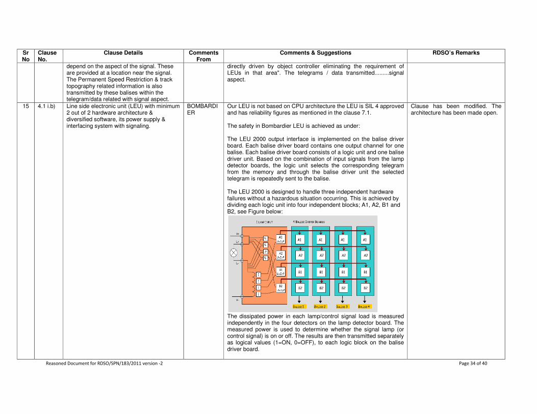
Reasoned Document for RDSO/SPN/183/2011 version -2 Page 34 of 40
Sr No
Clause No.
Clause Details Comments From
Comments & Suggestions RDSO’s Remarks
depend on the aspect of the signal. These are provided at a location near the signal. The Permanent Speed Restriction & track topography related information is also transmitted by these balises within the telegram/data related with signal aspect.
directly driven by object controller eliminating the requirement of LEUs in that area". The telegrams / data transmitted.........signal aspect.
15 4.1 i.b) Line side electronic unit (LEU) with minimum 2 out of 2 hardware architecture & diversified software, its power supply & interfacing system with signaling.
BOMBARDIER
Our LEU is not based on CPU architecture the LEU is SIL 4 approved and has reliability figures as mentioned in the clause 7.1. The safety in Bombardier LEU is achieved as under: The LEU 2000 output interface is implemented on the balise driver board. Each balise driver board contains one output channel for one balise. Each balise driver board consists of a logic unit and one balise driver unit. Based on the combination of input signals from the lamp detector boards, the logic unit selects the corresponding telegram from the memory and through the balise driver unit the selected telegram is repeatedly sent to the balise. The LEU 2000 is designed to handle three independent hardware failures without a hazardous situation occurring. This is achieved by dividing each logic unit into four independent blocks; A1, A2, B1 and B2, see Figure below:
The dissipated power in each lamp/control signal load is measured independently in the four detectors on the lamp detector board. The measured power is used to determine whether the signal lamp (or control signal) is on or off. The results are then transmitted separately as logical values (1=ON, 0=OFF), to each logic block on the balise driver board.
Clause has been modified. The architecture has been made open.

Reasoned Document for RDSO/SPN/183/2011 version -2 Page 35 of 40
Sr No
Clause No.
Clause Details Comments From
Comments & Suggestions RDSO’s Remarks
The selected telegram that is sent to the balise is assembled from four quarters sent by the four ASICs in a specific order, one after the other. In this regard, the synchronization of the four ASICs, sending one quarter of the telegram each, is the key process that results in a stream of bits that reconstructs a complete and coherent balise telegram on the output line, from the LEU 2000 to the balise. If there is an error, the function is disabled.
At any time, a given logic block (A1 for instance) “knows” only two quarters of the selected telegram: the quarter that it sends and the quarter that it checks (coming from B2 in this example). However, the logic block A1 is totally “unaware” of the information sent by the logic blocks A2 and B1. When the balise does not receive a telegram from the LEU 2000, it will transmit an internally stored default telegram, which is a fixed telegram, with information indicating that no telegram has been received from the LEU 2000. Each balise driver board is programmed individually i.e. it is possible for one LEU 2000 to control several completely different balise groups, based on information from several signals. We request RDSO to only mention the safety integrity level achieved by equipment shall be as per clause 4.19 & availability shall be as per 7.1 of RDSO/SPN/183/2010 Ver-2 Draft specification. RDSO shall not mention about the safety concept but shall mention about achieving the safety and availability.
Reasoned Document for RDSO/SPN/183/2011 version -2 Page 36 of 40
Sr No
Clause No.
Clause Details Comments From
Comments & Suggestions RDSO’s Remarks
Hence; we request to modify the clause and remove “2 out of 2 hardware architecture & diversified software” requirement.
16 4.1 ii.a) On Board Computer (OBC) with minimum 2 out of 2 hardware architecture & diversified software.
BOMBARDIER
We request RDSO to only mention the safety integrity level achieved by equipment shall be as per clause 4.19 & availability shall be as per 7.1 of RDSO/SPN/183/2010 Ver-2 Draft specification. RDSO shall not mention about the safety concept but shall mention about achieving the safety and availability. Hence; we request to modify the clause and remove “2 out of 2 hardware architecture & diversified software” requirement.
Clause has been modified. The architecture has been made open.
17 4.1 ii.d) Balise Transmission Module (BTM) with minimum 2 out of 2 hardware architecture & diversified software.
BOMBARDIER
We request RDSO to only mention the safety integrity level achieved by equipment shall be as per clause 4.19 & availability shall be as per 7.1 of RDSO/SPN/183/2010 Ver-2 Draft specification. RDSO shall not mention about the safety concept but shall mention about achieving the safety and availability. Hence; we request to modify the clause and remove “2 out of 2 hardware architecture & diversified software” requirement.
Clause has been modified. The architecture has been made open.
18 4.17 The TPWS track-side system shall interface with the signalling system without affecting normal working & safety of signalling system. It shall take input regarding signal aspect through potential free contacts of the Lamp Checking Relays (ECRs).
BOMBARDIER
We request you to consider other solutions such as direct control of balise with object controllers wherever possible. Hence, request you to add " In case of interlocking renewal the balise can also be controlled directly by the object controller system of the interlocking"
For standardization, only one mode of interfacing has been defined in the spec.
19 5.14 Isolation of TPWS: On board system shall have provision for isolation to cater for failure situation which shall result in disconnection of the system from the locomotive braking system. This shall be indicated to the driver by means of a visual indication which shall be available even if SDMI/DMI has failed. To avoid accidental/ unwarranted use, the isolation arrangement of the equipment must be protected and sealed. Isolation of system must be recorded by the system as well as recorded in a non-resettable veeder counter.
BOMBARDIER
During isolation of the onboard system (by mean of Isolation Switch) all connection to the brake system will be bypassed and additional EB SIFA valve will be energized by the vehicle battery. Isolation of the system is indicated to the driver by means of a dark DMI. However if this is not considered as sufficient, an additional contact can be implemented into the isolation switch and an alarm lamp can be then lit. Isolation switch can be sealed to prevent unauthorized isolations. All isolation will be recorded by proposed JRU and the stored data inside JRU can not be erased nor manipulated by unauthorized personnel. Hence, we propose to eliminate the requirement of non-resettable veeder counter.
The requirement is based on clause no. 4.1.6.3a of ETCS FRS ver.4 .50. The clause details as “A clear indication shall be given to the driver, that ETCS has been isolated, even if the normal ETCS DMI is defective.” Indication of TPWS isolation is required even in case of DMI/SDMI failure e.g. blanking of DMI screen. Non-resettable counter is also necessary so that even without downloading the data from JRU, number of EB application cases could be known.
20 5.16.1 System shall be provided with diagnostic functions, which can be accessed through PC/ laptop, and a standard interface cable
BOMBARDIER
Trackside Diagnostics: The need and level of diagnostic functions is to some extent depends
The clause has been modified for clarity & sub-clauses made separate for On-board & track side

Reasoned Document for RDSO/SPN/183/2011 version -2 Page 37 of 40
Sr No
Clause No.
Clause Details Comments From
Comments & Suggestions RDSO’s Remarks
connected to the diagnostic interface of train borne computer and track side equipment to download or upload data. Memory capacity of system shall be sufficient to keep log of minimum last one-week train running data. The memory shall keep log on First-In-First-Out basis.
on the LEU implementation. Bombardier’s implementation is based on PCB's with ASIC's instead of microprocessors and software which creates a more reliable product and reduces the need for those maintenance functions that normally are required for microprocessors based system. The diagnostic functionality in the Bombardier LEU is performed by a separate LEU monitoring board that can provide information to e.g. an external SCADA system. The LEU monitoring board is normally offered as an option since the MTBF of LEU is over 800,000 hrs in combination with no need for preventive maintenance which makes it possible to achieve the customer availability requirements also without monitoring board.
equipments.
21 5.19 Interoperability: The On Board system of a manufacturer shall be compatible & interoperable with Balise of another manufacturer & vice versa. Similarly, Balise and LEU of different manufacturers shall be interoperable with each other.
BOMBARDIER
Please add "Valid for systems and products delivered in compliance with identical versions of the UIC/UNISIG specifications". Also we would like clarify that interoperability is only achieved if the products are compliant with the same version of the UIC/UNISIG specifications.
The interoperability with the TPWS systems existing on Indian Railways has to be ensured.
22 6.18.2 Red light & Green light indicating respectively the faulty & healthy condition of On Board TPWS. Non-resettable type electromechanical counter for recording the cases of emergency brake application.
BOMBARDIER
The Red light & Green Light functionality shall be removed as this functionality is achieved via DMI during the Start of Mission phase. The onboard system will automatically undergo start up healthy tests. All tests are initiated automatically and if some part of the system is found faulty, a faulty message will be displayed on the driver’s DMI. The onboard system will not be ready for operation and must be maintained. On the other hand if all start up tests are successful, this will also be indicated on DMI and the Driver will be allowed to start the operation. During the train run, if some onboard fault occurs this will also be immediately indicated on the DMI and an alarm will be given to the driver. The system will also automatically apply brake, which can be released when the train has fully stopped. Further action depends on the type of fault, however if the fault does not recover, the driver has to switch OFF the onboard then the DMI becomes dark as a best indication to the driver that the onboard system is not working. In stead of a mechanical counter Bombardier proposes the use of JRU to register any type of emergency brake application (authorized and non authorized actions). JRU is also an integrated standard part of any ERTMS system and have excellent data storage functionality. The stored data inside JRU cannot be erased nor manipulated by unauthorized personnel.
The requirement of ‘TPWS Healthy’ & ‘TPWS Faulty’ indications is in addition to the indications existing on DMI/ SDMI. These additional indications shall be prominent & will immediately attract the attention of the Driver. Therefore, the requirement as mentioned in the clause is considered necessary.
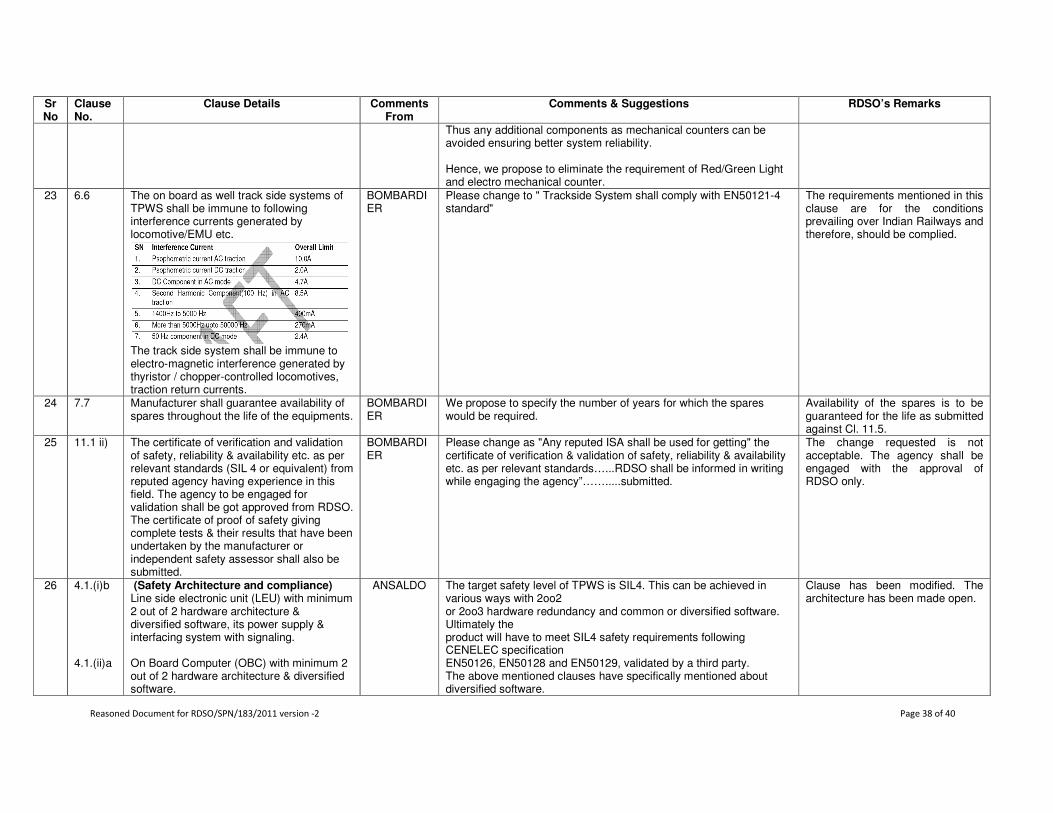
Reasoned Document for RDSO/SPN/183/2011 version -2 Page 38 of 40
Sr No
Clause No.
Clause Details Comments From
Comments & Suggestions RDSO’s Remarks
Thus any additional components as mechanical counters can be avoided ensuring better system reliability. Hence, we propose to eliminate the requirement of Red/Green Light and electro mechanical counter.
23 6.6 The on board as well track side systems of TPWS shall be immune to following interference currents generated by locomotive/EMU etc.
The track side system shall be immune to electro-magnetic interference generated by thyristor / chopper-controlled locomotives, traction return currents.
BOMBARDIER
Please change to " Trackside System shall comply with EN50121-4 standard"
The requirements mentioned in this clause are for the conditions prevailing over Indian Railways and therefore, should be complied.
24 7.7 Manufacturer shall guarantee availability of spares throughout the life of the equipments.
BOMBARDIER
We propose to specify the number of years for which the spares would be required.
Availability of the spares is to be guaranteed for the life as submitted against Cl. 11.5.
25 11.1 ii) The certificate of verification and validation of safety, reliability & availability etc. as per relevant standards (SIL 4 or equivalent) from reputed agency having experience in this field. The agency to be engaged for validation shall be got approved from RDSO. The certificate of proof of safety giving complete tests & their results that have been undertaken by the manufacturer or independent safety assessor shall also be submitted.
BOMBARDIER
Please change as "Any reputed ISA shall be used for getting" the certificate of verification & validation of safety, reliability & availability etc. as per relevant standards…...RDSO shall be informed in writing while engaging the agency”…….....submitted.
The change requested is not acceptable. The agency shall be engaged with the approval of RDSO only.
26 4.1.(i)b 4.1.(ii)a
(Safety Architecture and compliance) Line side electronic unit (LEU) with minimum 2 out of 2 hardware architecture & diversified software, its power supply & interfacing system with signaling. On Board Computer (OBC) with minimum 2 out of 2 hardware architecture & diversified software.
ANSALDO The target safety level of TPWS is SIL4. This can be achieved in various ways with 2oo2 or 2oo3 hardware redundancy and common or diversified software. Ultimately the product will have to meet SIL4 safety requirements following CENELEC specification EN50126, EN50128 and EN50129, validated by a third party. The above mentioned clauses have specifically mentioned about diversified software.
Clause has been modified. The architecture has been made open.

Reasoned Document for RDSO/SPN/183/2011 version -2 Page 39 of 40
Sr No
Clause No.
Clause Details Comments From
Comments & Suggestions RDSO’s Remarks
4.1.(ii)d
Balise Transmission Module (BTM) with minimum 2 out of 2 hardware architecture & diversified software.
We suggest this should be left open mentioning as “common or diversified software”.
27 5.3 Calculation of Speed The system shall incorporate the necessary hardware and software module for accurate calculation of the train speed duly accounting for wheel slip/skid corrections. Manufacturer shall submit the details of the speed calculation module along with the supporting international standards/practices being followed world over for the same. Calculation of speed shall be with an accuracy of ±2% subject to maximum of ±2 kmph. Further, the variation in wheel diameter due to normal wear during time period between two loco maintenance schedules shall not affect accuracy beyond the limits specified in this clause.
ANSALDO According to UNISIG subset 041 on Performance Requirements for Interoperability, clause : 5.3.1.2 states that Accuracy of speed known on-board : Value ± 2 km/h for speed lower than 30 km/h, then increasing linearly up to ± 12 Km/h at 500 km/h.” With reference to the UNISIG specification mentioned above, we request you to kindly amend the description of the clause accordingly.
The requirement was there in ver-1 of the specification also. No other vendor has given any comment on this requirement. The requirements as mentioned in the clause should be complied with.
28 6.2 Protection of cards from dust All the cards shall be suitably protected, enclosed and provided with mechanical dust proofing covers to avoid dust ingress and then mounted in a robust metallic housing so that entire assembly is capable of withstanding shocks, vibrations, electromagnetic induction and electrical surges etc.
ANSALDO The component density of the PCBs used for TPWS is quite high and it needs some air Circulation to avoid hot spots. Enclosing the PCBs inside a mechanical enclosure will Trap the heat inside. Protection of the modules from dust and EMI/EMC may be achieved at the rack and Cabinet level. Thus it is suggested to keep the implementation open for the supplier to Satisfy the requirement.
The clause has been modified.
29 6.7 Electromagnetic compatibility Electromagnetic compatibility of the entire On-board equipment as well as track side equipments including interlinking cables shall comply with European Standards EN50238 for Railway Applications – Compatibility between rolling stock & train detection system and EN 50121 for Railway Applications – Electromagnetic Compatibility, as applicable. Adequate provisions should be made in the design for suppression of internal transients, spikes and to withstand external transients, spikes and surges as per limits laid down in IEC-60571.
ANSALDO
The clause mentioned about EMC compatibility referring to both EN50238 and EN50121. Please clarify which specific requirements you would like to have for Compliance.
The clause is modified as under: ‘Electromagnetic compatibility Electromagnetic compatibility of the entire On-board equipment as well as track side equipments including interlinking cables shall comply with European Standards EN 50121 for Railway Applications – Electromagnetic Compatibility and On-board equipment shall also comply with EN50238 for Railway Applications – Compatibility between rolling stock & train detection system. Adequate provisions should be made in the design for suppression of internal
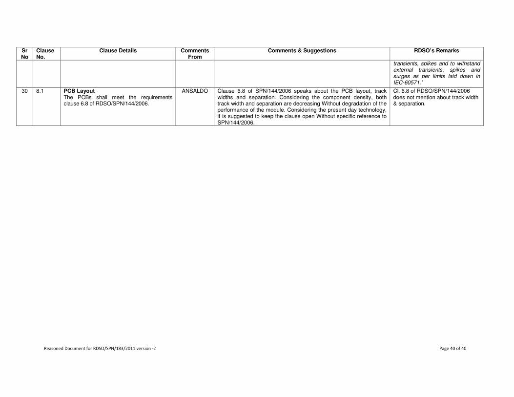
Reasoned Document for RDSO/SPN/183/2011 version -2 Page 40 of 40
Sr No
Clause No.
Clause Details Comments From
Comments & Suggestions RDSO’s Remarks
transients, spikes and to withstand external transients, spikes and surges as per limits laid down in IEC-60571.’
30 8.1 PCB Layout The PCBs shall meet the requirements clause 6.8 of RDSO/SPN/144/2006.
ANSALDO
Clause 6.8 of SPN/144/2006 speaks about the PCB layout, track widths and separation. Considering the component density, both track width and separation are decreasing Without degradation of the performance of the module. Considering the present day technology, it is suggested to keep the clause open Without specific reference to SPN/144/2006.
Cl. 6.8 of RDSO/SPN/144/2006 does not mention about track width & separation.