isolatek international presents i ns · pdf fileisolatek international • presents i ns...
TRANSCRIPT

ISOLATEK INTERNATIONAL PRESENTS • I ns
Information & Solutions For Design & Construction Professionals
JUNE 1997
Restrained
vs.
Unrestrained
To most structural engineers, code
officials and architects, the terms
"Restrained" and "Unrestrained"
are typically interpreted as
referring to the connection of
structural elements at ambient
temperatures. However, in the fire
protection industry, restrained and
unrestrained are addressed at
elevated temperatures, introducing
the concept of "thermal restraint".
The issue of thermal restraint
causes some controversy in
determining whether an assembly
should be considered restrained
or unrestrained. The classification
of an assembly in one of these
categories has a bearing on the
thickness of spray-applied fire
resistive material (SFRM) needed to
satisfy code requirements. Higher
SFRM thicknesses are typically
required for unrestrained ratings.
In order to clarify whether an
assembly should be considered
restrained or unrestrained, one may
refer to the actual "Fire Test Stan
dards of Building Construction and
Materials". According to Appendix
X3 of ASTM Standard E 119 and
Number 3
Appendix C of UL (Underwriters
Laboratories) Standard 263: "Floor
and roof assemblies and individual
beams in buildings shall be
considered restrained when the
surrounding or supporting structure
is capable of resisting substantial
thermal expansion throughout the
range of anticipated elevated
temperatures. Construction not
complying with this definition is
assumed to be free to rotate and
expand and shall therefore be
considered as unrestrained."
To assist in determining this
condition, ASTM Standard E119
and UL 263 also list general
construction classifications and
whether they denote a restrained
or unrestrained condition. This
table of claSSifications, which at
one time appeared in the UL Fire
Resistance Directory, has been
attached for reference purposes.
According to UL, this information
is intended as a guide for the
determination of restrained
conditions and is not meant as a
specification. Engineering judgment
must therefore be exercised to
determine what constitutes restraint

to "substantial thermal expansion".
Furthermore, page 14 of the 1997
UL Directory states the following:
"Restrained conditions for the fire
test assemblies are provided by
constructing floor, beam and roof
test assemblies within nominal 14 ft
x 17 ft frames of composite steel/
concrete cross sections having an
approximate stiffness (EI/L) of
850,000 kip-in and 700,000 kip-in
along the 14 ft and 17 ft sides,
respectively." This description
provides structural engineers with
the stiffness of UL's test frame so
that they have a basis of compari
son when determining conditions
of restraint for beams on a project.
Due to the level of analysis and
interpretation required, there is
often confusion as to whether a
building's construction shall be
specified as restrained or
unrestrained. Ultimately, the
determination of the conditions
of restraint remain in the hands
of the structural engineer and the
authority having jurisdiction. The
level at which these conditions are
followed by various code bodies
differs between organizations.
Both the National Building Code
(BOCA) and Standard Building
Code (SBCCI) address restrained
vs. unrestrained criteria referring
directly to Appendix X3 of ASTM
E119. The Uniform Building Code
(ICBO) criteria requires that all
construction design be considered
unrestrained unless proven
otherwise.
After determining restrained vs.
unrestrained conditions, the
appropriate restrained or
unrestrained fire resistance rating
must be utilized. Restrained and
unrestrained fire ratings specified
for both beams/joists and assemblies
are used to determine the required
fire protection material thicknesses
which are listed in the UL Directory.
Due to the difference in thickness
requirements between restrained
and unrestrained hourly ratings,
this determination can often have
a significant effect on both the
fireproofing requirements and life
safety integrity of the building.
~IDll E 119
:a.5.1 Included sball be a statement to the effect that the con5'.ruction truly represents field construction. If the cons:;rtlction does not represent typic.:ll field construction, then the deviations shall be noted.
:a.5.2 If con5'uuctlon is unsymmetrical (has diffw:nt details on ""cn facer be sure to indicate the fa"" exposed to fir<: with comments on fire resistance from the opposite side.
:a.5.3 Fire test. :a.6 Summarize Results. include: :a.6.1 Endurance time, X2.6.2 Nature of failure, and :a.6.3 Hose stream test results. :a.7 List Official Observers-Signatures of responsible
pcf'Ons. :a.8 Appendix-Include all data not specifically required
bv test 5'.andard, but useful to bener unde:standing of test ~u1ts. Special observations for Building Code approvals should be in appendix.
X2.9 Pictures-All taken to show what =not be covered in the report or to clarify.
X2.9. I Assembly in construction. X2.9.2 Exposed face prior to fire test. X2.9.3 Unexposed face at start of enduran"" test; include
recording equipment when possible. X2.9.4 Unexposed fa"" at end of fire endurance test. X2.9.5 Exposed face at end of fire e"durance test. X2.9.6 Unexposed face at e"d of fire exposure before bose
test. X2.9.7 Exposed face at end of fire exposure before bose
test. X2.9.8 Exposed face after bose stre:1m test. X2.9.9 Unexposed face after bose stream test. X2.10 It is essential to bave the following: X2.10.1 De'..ai1ed drawing of test assemblv. X2.10.2 Pictures (X2.9.1, X2.9.4, X2.9.8: and X2.9.9) for
every test re;xlrt.
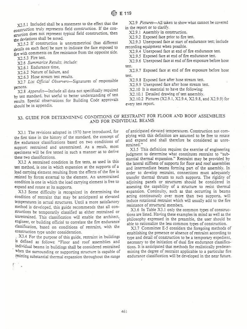
X3. GUIDE FOR DETER.\.llNING CmmmONS OF RESTRAINT FOR FLOOR Al'ID ROOF ASSEMBLIES Al'iD FOR INDrYIDUAL BEAMS
X3.1 Tbe revisions adopted in 1970 have introduced, for the first time in the history of the standard, the concept of fire endurance classifications based on two conditions of support: restrained and unrestrained. As a result, most sp<cimens will be fire tested in such a manner as to derive the<...e two classifications.
X3.2 A restrained condition in fire tests, as used in this test method, is one in which expansion at the supportS of a load carrying e!eme:n resulting from the effects of the fire is rOsisted by forces external to the element. An unrestrained condition is one in which the load carrying element is free to expand and rotate at its supportS. . X3.3 Some difficulty is recognized in detertnining the Condition of restraint that may be anticipated at elevated temperatures in actual structures. Until a more satisfactory method is developed, this guide recommends that all constructions be temporarily classified as either restrained or unrestroined. This classification will enable the architect, engineer, or building official to correlate the fire endurance classification, based on conditions of restraint, with the construction type under consideration. .' X3.4 For the purpose of this guide, restraint in buildings IS defined as follows: "Floor and roof assemblies and
. individual be:tms in buildings shall be considered restrained wben the surrounding or supporting structure is capable of !"SlSUng substantial thermal expansion throughout the range
~.
of anticipated elevated temperatures. Construction not complying with this definition are assumed to be free to rotate and expand and shall therefore be considered as unrestrai ned."
X3.5 Tnis definition requires the exercise of engine:::ing judgment to determine what con5'.itutes restraint to "substantial thermal expansion." Restraint may be provided by the lateral stiffness of supports for floor and roof assemblies and intermediate be:tms forming part of the assembly. In orde, to develop restraint, connections must adequately transfer thermal thrus-.5 to such supports. The rigidity of adjoining panels or structures should be considered in
. assessing the capability of a structure to resist thermal e~pansion. Continuity, such as that occurring in be=lms acting continuously over more than two supports, will induce rotational restraint which will usuallv add to the nre
461
resistance of structural members. . X3.6 In Table X3.1 only the common types of construc·
tions are listed. Having these e"mples in mind as well as the philosophy expressed in the preamble, the user should be able to rationalize the less common types of construction.
X3.7 Commine:: E-5 considers the foregoing methods of est.ablish.ing the presence or absence of restraint according to typ< and det:lil of construction to be a temporarY expedient, necessary to the initiation of dual fire enduran~e classifications. It is anticipated that methods for realistically prede~ermining the degree of restraint applicable to a particular fire endurance classification will be developed in the ne:lf future.

~@l E 119
TABLE X3.' Construction Claulfication, RHlnlined one! lJnrestroined
I. WaD beanng: Sngle span and simply supported .-ld spans 01 tnL.itipie bays:;l
(1 ) Open-wl!'b steel joists cr steel beams, supporting c::c:::nc:at.e Iiab, precast Lrits, cr metal decking (2) Concrete SIaDs, precast 1SIits. or metal dEId<ng
Interic:t' spans of muItxpIe bays: (1 ) Open.weo steel joists. steel beams or metal decki"lg. ~ ccntinl.JOtJS c:onc:re1e slab (2) Opeo-web steel psts ex steel beams, supporti:ng precut \rit$ 01 metal c:Iedtng (3) Cast-irl-place ~ si8b systems (4 ) Precast c:onaete 'NtIere the potential thermal expansion is resisted by adjacent c:onstrucXln
U. Steel fratrung: (1 ) Steel be!ms ~. riveted. or batted to the fna'rW'Ig members (2) All types of cast-in--pLace ftoor and roof systems ($t..Jr:I as ~, 1\at slabs, pari jorsts. and watne 1iab3) where tr1e
1'Joof or roof system is S8OJI'ed to the frarrw".g rnem.bers (3) All types of prela.bricaled 1'Joof cr roof systems ~ the S'IrI..IC':Ut'a members are S8O.JrtId to the framing members and the
potential trlermaJ expanSlOl"\ 01 the l'\cx)r cr roof system Is reseted by the framing system 01 the ad~ noa a roof construction •
III. Conaete framing: (1 ) Beams seo.Jfely fastened to the ftaming members (2) All types of east4l-p(ace floor or roof systems (SIJCtl as beafn-.&nd-slabs, flat stabs, pan joists. and wattle Slabs) Where the
noor system is as! WTth the f'rammg members (3) [menor and extenor spans of precast systems wTth easl~ joints resu'trng n l'1!Straint eq.jvaJent to tf'.8t which would
eXist 11'\ OO""odltton 111 (1)
(4) An types of prefabncaled t\oor or roof systems ~ the structural members are secured to suc:t'I systerr'.$ and the potential tTlermal expartSlOl"l of the ftoor ex roof systems is resisted by the framing system or the adjOlnll"lg ftoor or roof c:onstnJC'tJon.
IV. Wood c:onstnJctJOn: An types
restrained ... trained
U'V'estr lined
,. FlOor and roof systems can be ~ed restrained when they are bed into walls witrI or wttI'v:M tire beams , the waDs being designed anc:l oetailed to resisllhermal thrUst trom the noor or rool system .
• For example. reSIstance to potential thermal expansion is e:onsidered to be ICI'Wved Wflen:
(1) Continuous structuraJ eonc:-ete topping is used. (2) The s~ce between the ends 01 precast units or between the ends 01 unItS and the vertical face of supportS is filled with concrete or rT'Qftar , or
(3) The space between the ends of precast units and the vertical laces of supportS. or betwffn the ends 01 solid or holJcJw core s.la.b units does not exceed 0.25 " 01 the Iengtt'I tor norma/ Weight eonaete members or 0.' " 01 the length/Of stn..lC'!.uraJ Iightwel9ht concrete members.
X4. METIfOD OF CORRECTING TIRE ENDUR<l.NCE FOR CONCRETE SLABS DETERMINED BY Ul\EXPOSED SURFACE TEMPERATURE RISE FOR NONSTANDARD MOISTURE COi'<TINT
X4.1 Scope
X4.1.I The standard fire endurance is the time determined by unexposed surface temperature rise of a test specimen at a standard moisture leveL
X4. 1.2 This appendix gives a procedure to correct the fire endurance of unprotected venical or horizontal slabs (solid or hollow), made from essentially inorganic building mate· rials; and conditioned on both sides, when moisture content at the time of test is other than at a standard moisture leveL
X4.1.3 From among the common inorganic building materials, only the hydrated portland cement products can hold (after due conditioning in accordance with Section II) sufficient amount of moisture to affect noticeably the result of the fire test. Consequently, correcting the experimental fire endurance of constructions containing less than 5 volume % of portland cement paste is not necessary.
X4.2 Symbols
X4.2.1 The symbols used in this Appendix are defined as foll ows: A = factor characterizing the drying conditions (see
b
FE RH
=
= =
Table X4.1), fact or characterizing the penneability of the spec· imen (see Table X4.2), fire endurance of specimen, h, relative humidity,
462
m
m. m, m,
m"
m,
v
= moisture content, volume fraction ft' / ft' or em'/ em' ,
= average moisture content of test specimen, = average moisture content of cement paste, = nominal equilibrium moisture content of cement
paste for a given RH (see Table X4.3). = equilibrium moisture content of cement paste at the
standard RH level (see Table X4.3). = average moisture content of a standard conditioned
concrete specimen of same concrete and cement paste volume as the test specimen, and
= volume fraction of cement paste, ft '/ft ' or cm'/ emJ
TABLE X4.1 Factor Characterizing Drying Conditions
Factor A tor Portland Cement
ConcOt>onng Envronment Middepth RH of
Test Spec:men, " NonnaJ Ugnt·W";ghI
Weight Conaete eona.te 60 to 8O-F (15.6 to 26.7-C) any , .0 1.0 8~phenc a:nditions
120 to 160·F (48.9 to 70 to 75 0.7 0.7 71 .1·C) 20 to 35" RH
190 to 200·F (87 .8 to 70 to 75 0.45 0 93.J-C) 0 to 5 ~ RH
120 to 200°F (48.9 to less than 70 0 0 9J.3-C) 5 to 35 ~ RH

14 nRE RESISTANCE DIRECTORY (BXRH)
FIRE RESISTANCE RATINGS - ANsIjU1263 (BXUV)-[ontinued The: hourly fire ratings for load bearing wood stud walls were derived with a
superimposed load applied to the waH assembly intended to theoretically deveLop maximum working stresses not exceeding the design vaLues published in the Supplement to the 1991 Edition of the National Oesign Specification for wood construction. In addition. the design load per square inch of cross sectional area for any wood stud shalt not nceed 385 psi.
Wood stud walls may contain fire retardant treated studs as well as untreated wood studs.
Steel Studs The dimensions and gauge of steel studs are minimums. The hourly ratings
apply when the steel studs ire of it heavier gauge and/ or larger dimensions than specified in a Design. The superimposed load of bearings walls utilizing st~l studs shall be based on the capacity of the studs as determined by the 1986 edition of the AL'l Specification for the Design of Cold Formed Steel Structural Members with the December 11, 1989 Addendum.
Gypsum Board Joint Treatment The joints in gypsum board applied to wood or steet studs may either be
exposed of covered with joint tape and joint compound for that portion of the joint above a suspended ceiling which is part of a fire resistive fioor~ceiling or roof~ceilin9 assembly.
Electrical Outlet Boxes The category of "Outlet Boxes and Fittings Classified for Fire Resistance
(CEYY) includes Classification for nonmetallic outtet and switch boxes for use in wall or partition assemblies. The information provided for each Classification includes the model numbers for the Classified products. a description of the rated assemblies. the spacing limitations for the boxes and the installation details.
Listed single and double gang metallic outlet and switch boxes with metallic or nonmetallic cover plates may be used in bearing and nonbearing wood stud and steet stud walls with ratings not exceeding 2 h. These walls shalt have gypsum wallboard facings similar to those shown in Design Nos. U301. U411 and U42S.
The surface area of individual metallic outlet or s'Hitch boxes shall not exceed 16 sq in. The aggregate sum.ce area of the boxes shall not exceed 100 sq in, per 100 sq ft of wall suriace, Boxes located on opposite sides of walls or partitions shall be separated by a minimum horizontal distance of 24 in. Boxes shaU not be instaUed on opposite sides of walls or partitions of staggered stud construction. The minimum separation distance may be reduced when '"Wall Opening Protective Materials" (ClIV) are installed according to the requirements of their Classification,
The metallic outlet or switch boxes shall be securely fastened to the studs and the opening in the wallboard facing shaU be cut so that the clearance between the box and the wallboard does not exceed 1/8 in,
During the fire test. the furnace pressure is maintained at a positive pressure level of at least 0.01 in. of water. as measured 0.78 in. (20 mm) from the face ~xposed to the furnace fire,
COMMENTARY ON DETERMINING CONDmONS OF RESTRAlNT FOR FLOOR AND ROOF ASS,MBUES AND
FOR INOIVlDUAL BEAMS Classifications of fioor and roof assemblies and individual beams include
restrained and unrestrained ratings. The Standard for Fire Tests of Building Construction and Materials. ANSI/UL 263. and specifically Appendix C. provides general information with respect to the concept of these classifications.
Appendix C of Standard ANSIjUL 263 defines restraint in buildings as. -Hoor and roof assemblies and individual beams in buildings shall be considered restrained when the surrounding or supporting structure is capable of resisting substantial thermal e..xpansion throughout the range of anticipated elevated temperatures. Constructions not complying with this definition are assumed to be free to rotate and expand and shaH be therefore considered as unrestrained".
The restrained condition in fire tests is defined in Appendix C of the Standard as. ·one in which expansion at the supports of a load carrying element resulting from the effects of the fire is resisted by forces external to the etement"'. This definition may not be appropriate for conditions of re~raint. in actual structures. The Standard recognizes that the exercise of englne~nng judgement is required to determine what constitutes ~substantial thermal expansion" when determining the conditions under which the restrained or unrestrained ratings should be used.
Restrained conditions for the fire test assemblies are provided by constructing fioor. beam and roof test assemblies within nominal 14 ft by 17 ft frames of composite steel/concrete cross sections hav;ng an approximate stiffness (EI/ L) of 850,000 kip-in . and 700.000 Jcip-in. along the 14 ft and 17 ft sides. respectively. The frame stiffness remains constant throughout the fire test because the test frame is insulated from the fire environment. . W~~n applying the published restrained ratings. it is recognized ~at the lnd1V1dual responsible for the design of the fire-rated construction may ascertain tha~ a different degree of restraint may be provided to the build~ng assembly dunng a fire condition than was provided to the test sample dunng the fire test. Under these conditions. the designer may review the Con~itions of Acceptance for restrained and unrestrained assemb lies and beams \0 the Stand?rd ANSIjUL 263 for additional guidance when determining whetMer restraIned or unrestrained ratings should be specified.
nRE RESlSTANCE DIRECTORY (BXRH)
FIRE RESISTANCE RATINGS - ANSIjUl263 (BXUV)-[ontinued
Design No_ A002 Restrained Assembly Rating-2 Hr.
Unrestrained Assembly Rating-2 Hr. Unrestrained Seam Ratings-2 and 3 Hr_ (See Item 19)
cp .. <~.: ! ;.
7 Beam IS-SIS'
18
--
14 0@ ® \,-__ ~7 Section B-B
Beam-W6x1S.S. minimum size. 1. Normal-~eight Concrete-Siliceous aggregate. 1:2:2~ 1/ 4 mix. 5000 psi
compresswe strength. -2. ~teel Floor .and form Units*:-N?ncomposite galv units. AU 1-1/2 or 3
:", deep 24 tn. ~de 20/18. MSu mm cellular units. Welded to supports 12 10. O,c. max. Adjacent U01t$ button~punched or welded 36 in. O.L
Roll Form Prods.. Inc.-Types C15LF. 03lF. Alternate Constru~on-Composite units of the same type listed above may be used proVloed allowable loading is calculated on the basis of noncomposite design.
3, Hanger Clips-No, 18 MSG galv steel. 2~3/4 in. wide. 4 in. long. hooked at one en~ for attachment over male legs of floor units.
4. Hanger Wue-No. 12 SWG galv steel wire, min diam located at each c~rner of light fixtures and 48 in, O.c. along furring channels otherwise.
5, Au Ducts-Galv steel 22 gauge min thick steeL Total area of duct op~ni~g~ . not to exceed ?88 sq in. per each 100 sq ft of ceiling area. Area of mdlVlolJal duct openmg not to exceed 576 sq in. Max dimension of opening 30 in.; maximum clearance of duct outlet to lower flange or steel
LOOK FOR MARK ON PRODUCT