isolated gate drivers for industrial motor drives
TRANSCRIPT
DARA O’SULLIVAN
PCIM 2015
Isolated Gate Drivers for Industrial Motor Drives
®
2
Presentation Outline
► Industrial motor control► Gate drive functionality► Gate driver parts from ADI► System level benefits
3
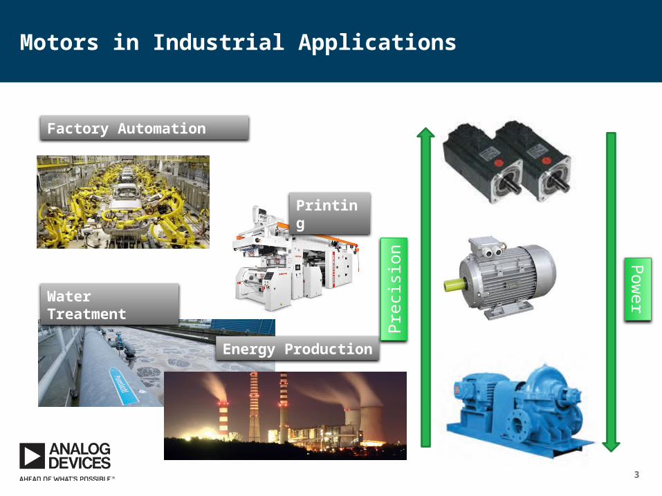
Motors in Industrial Applications
Water Treatment
Factory Automation
Energy Production
Printing
Pre
cisi
on Pow
er
4
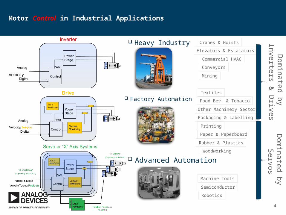
Motor Control in Industrial Applications
Advanced Automation
Heavy Industry
Factory Automation
Cranes & Hoists
Elevators & Escalators
Commercial HVAC
Conveyors
Mining
Textiles
Food Bev. & Tobacco
Other Machinery Sectors
Packaging & Labelling
Printing
Paper & Paperboard
Rubber & Plastics
Woodworking
Machine Tools
Semiconductor
Robotics
Dom
inated by Inverters &
Drives
Dom
inated by S
ervos
5
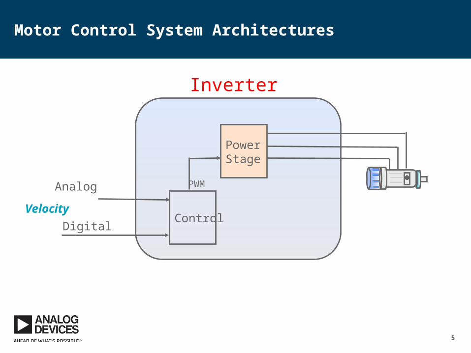
Motor Control System Architectures
PowerStage
ControlDigital
Velocity
PWM
Inverter
Analog
6
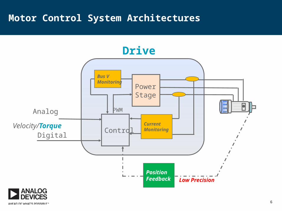
Low Precision
Motor Control System Architectures
PowerStage
ControlDigital
Velocity/Torque
PWM
Drive
Current Monitoring
Bus VMonitoring
Analog
PositionFeedback
7
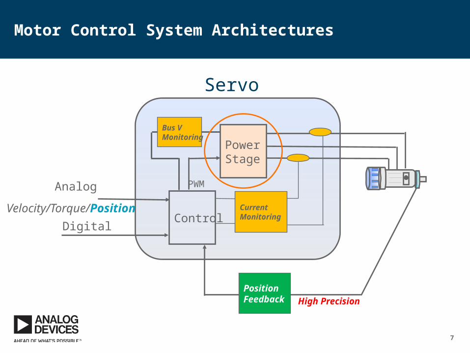
Motor Control System Architectures
PowerStage
ControlDigital
Velocity/Torque/Position
PWM
Servo
Current Monitoring
Bus VMonitoring
PositionFeedback
Analog
High Precision
8
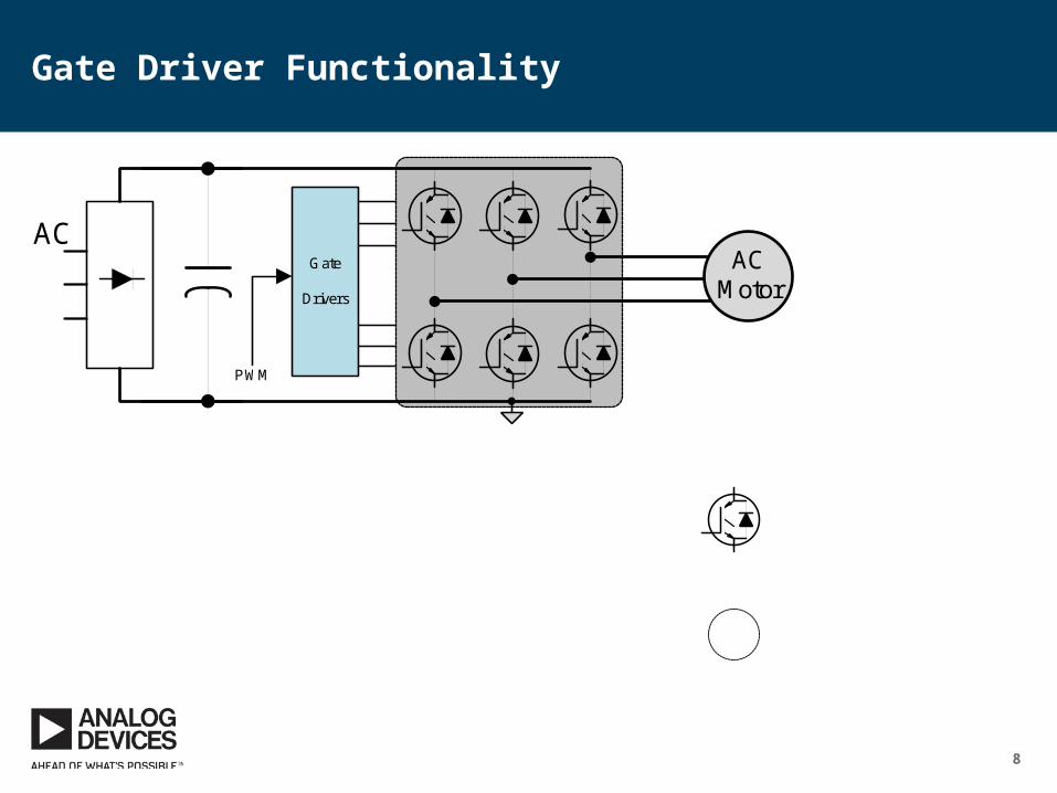
Gate Driver Functionality
ACMotor
ACGate
Drivers
PWM
DC+
E
C
G
ControlSignal (Vg-0)
DriveSignal(Vdrv-SN)
DC_gnd
ACMotor
U
V
W
From Phase U
From Phase W
0
Switch Node (SN)
VSN0-3.3V
0-15VPhase V
• Referencing of control signal
• Drive current
• Drive voltage levels
• Isolation
• Withstand large CM voltage swing
9
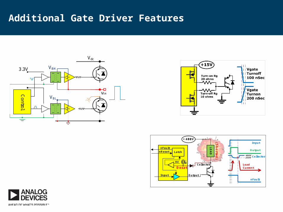
Additional Gate Driver Features
+400V (Shorted)
I nput
nFault
Desat
LOAD
Output
9V
nFaultnReset
Input
Output
CollectorX400V250V
Load Current
Collector
Latch
vSN
Vdc
VBH
Control
3.3V
VBL CgdZdriver
vGEVth
i=Cgd (dVSN/dt)
Spurious turn-on prevention
Short circuit prevention
Asymmetric switching
• Enhanced reliability• Optimised performance
10
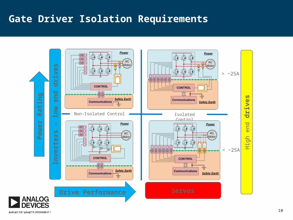
Gate Driver Isolation Requirements
< ~25A
> ~25A
Isolated ControlNon-Isolated Control
Servos
Hig
h en
d dr
ives
Inve
rter
s –
low
end
driv
es
Drive Performance
Pow
er R
atin
g
11
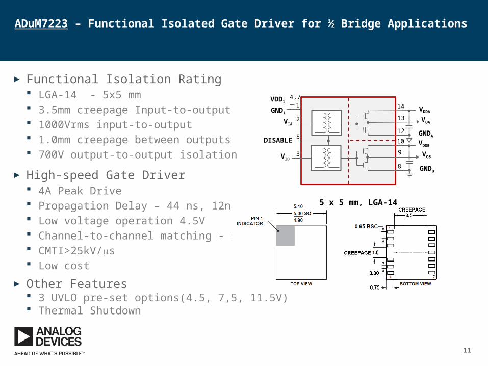
ADuM7223 – Functional Isolated Gate Driver for ½ Bridge Applications
► Functional Isolation Rating LGA-14 - 5x5 mm 3.5mm creepage Input-to-output 1000Vrms input-to-output 1.0mm creepage between outputs 700V output-to-output isolation
► High-speed Gate Driver 4A Peak Drive Propagation Delay – 44 ns, 12ns skew Low voltage operation 4.5V Channel-to-channel matching - 5ns CMTI>25kV/ms Low cost
► Other Features 3 UVLO pre-set options(4.5, 7,5, 11.5V) Thermal Shutdown
VOB
VOA
VDDA
VDDB
GNDA
GNDB
GND1
VIA
VIB
DISABLE
VDD11
4,7
2
5
3
14
13
12
10
9
8
5 x 5 mm, LGA-14
12
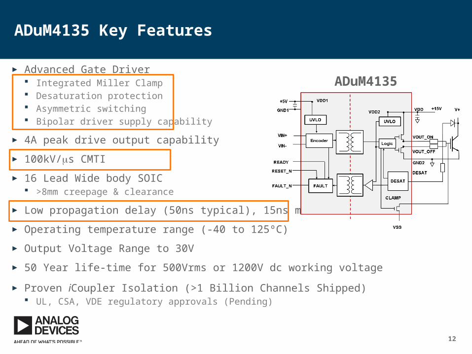
ADuM4135 Key Features
► Advanced Gate Driver Integrated Miller Clamp Desaturation protection Asymmetric switching Bipolar driver supply capability
► 4A peak drive output capability
► 100kV/ms CMTI
► 16 Lead Wide body SOIC >8mm creepage & clearance
► Low propagation delay (50ns typical), 15ns max skew
► Operating temperature range (-40 to 125ºC)
► Output Voltage Range to 30V
► 50 Year life-time for 500Vrms or 1200V dc working voltage
► Proven iCoupler Isolation (>1 Billion Channels Shipped) UL, CSA, VDE regulatory approvals (Pending)
ADuM4135
13
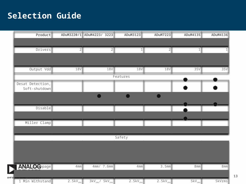
Selection Guide
Product ADuM3220/1 ADuM4223/ 3223 ADuM3123 ADuM7223 ADuM4135 ADuM4136
Features Basic Basic Basic Advanced
Drivers 2 2 1 2 1 1
Peak Output Current 4A 4A 4A 4A 4A, 4A
Output Vdd 18V 18V 18V 18V 35V 35V
Features
Desat Detection, Soft-shutdown
Fault, Ready, Reset
Disable
Bipolar Supply
Miller Clamp
Split Output
Safety
Working Voltage 400Vrms Basic
400Vrms Reinforced
1000Vdc Basic
400Vrms Basic
400Vrms Functional
500Vrms Reinforced
1200Vdc Basic
500Vrms Reinforced
1200Vdc Basic
Creepage 4mm 4mm/ 7.6mm 4mm 3.5mm 8mm 8mm
Package R-8 R-16/ RW-16 R-8 5 x 5 LGA RW-16 RW-16
1 Min Withstand 2.5kVrms 3kVrms/ 5kVrms 2.5kVrms 2.5kVrms 5kVrms 5kVrms
14
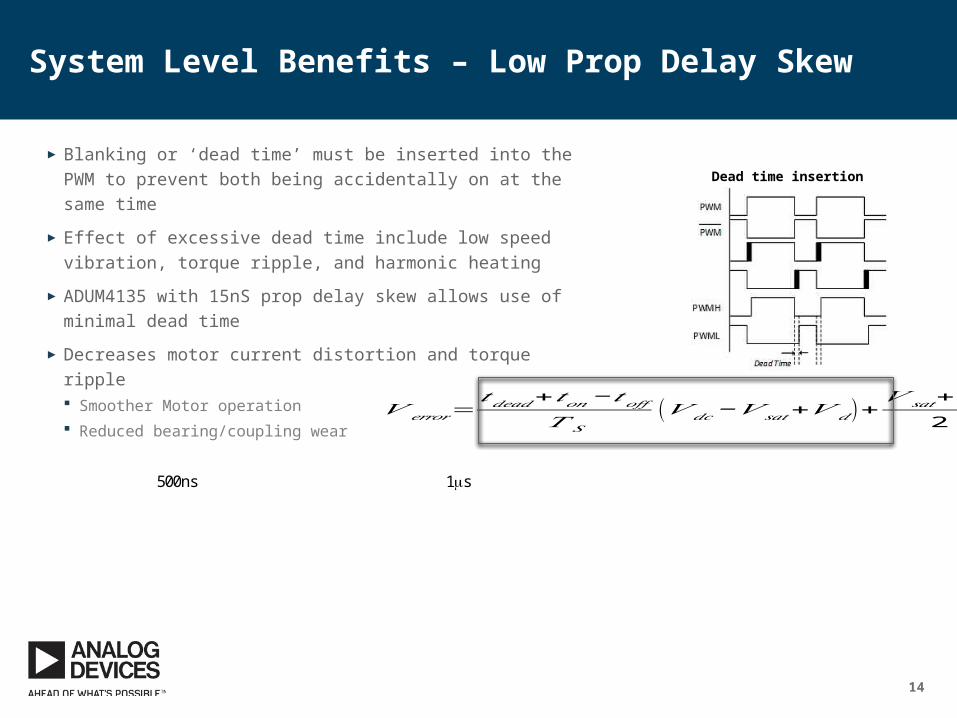
System Level Benefits – Low Prop Delay Skew
► Blanking or ‘dead time’ must be inserted into the PWM to prevent both being accidentally on at the same time
► Effect of excessive dead time include low speed vibration, torque ripple, and harmonic heating
► ADUM4135 with 15nS prop delay skew allows use of minimal dead time
► Decreases motor current distortion and torque ripple Smoother Motor operation Reduced bearing/coupling wear
Dead time insertion
500ns 1ms
𝑉 𝑒𝑟𝑟𝑜𝑟=𝑡𝑑𝑒𝑎𝑑+𝑡𝑜𝑛− 𝑡𝑜𝑓𝑓
𝑇 𝑆(𝑉 𝑑𝑐−𝑉 𝑠𝑎𝑡+𝑉 𝑑 )+
𝑉 𝑠𝑎𝑡+𝑉 𝑑
2
15
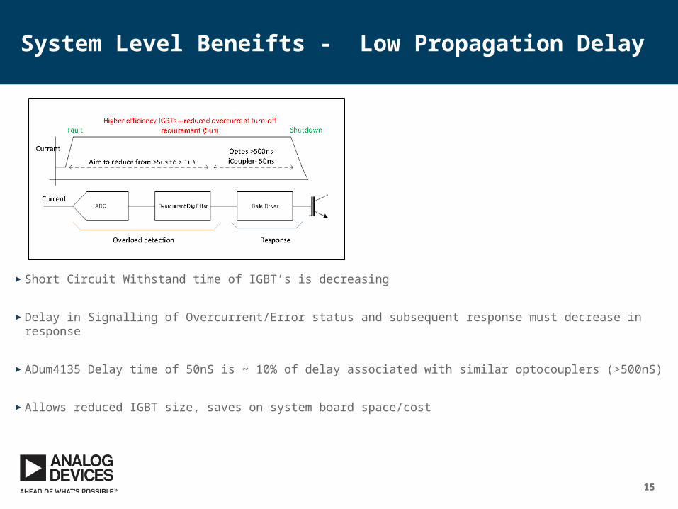
► Short Circuit Withstand time of IGBT’s is decreasing
► Delay in Signalling of Overcurrent/Error status and subsequent response must decrease in response
► ADum4135 Delay time of 50nS is ~ 10% of delay associated with similar optocouplers (>500nS)
► Allows reduced IGBT size, saves on system board space/cost
System Level Beneifts - Low Propagation Delay
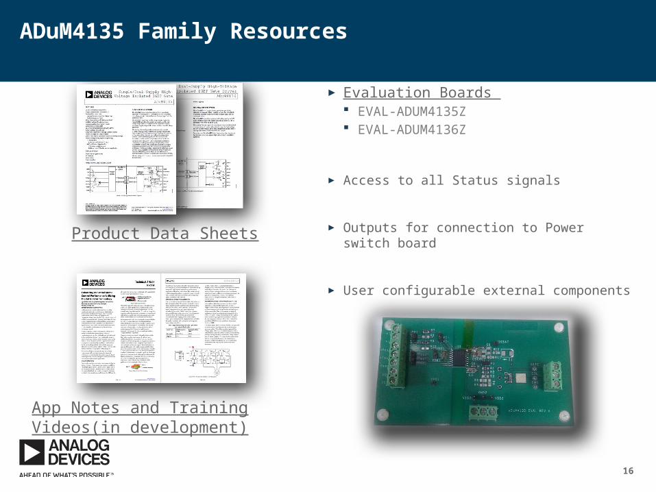
► Evaluation Boards EVAL-ADUM4135Z EVAL-ADUM4136Z
► Access to all Status signals
► Outputs for connection to Power switch board
► User configurable external components
16
ADuM4135 Family Resources
Product Data Sheets
App Notes and Training Videos(in development)
17
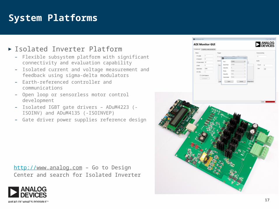
System Platforms
► Isolated Inverter Platform– Flexible subsystem platform with significant
connectivity and evaluation capability– Isolated current and voltage measurement and
feedback using sigma-delta modulators– Earth-referenced controller and communications– Open loop or sensorless motor control development– Isolated IGBT gate drivers – ADuM4223 (-ISOINV)
and ADuM4135 (-ISOINVEP)– Gate driver power supplies reference design
http://www.analog.com – Go to Design Center and search for Isolated Inverter

18
Further Education
► www.analog.com/webcasts
19
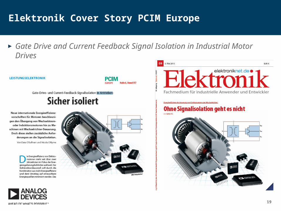
Elektronik Cover Story PCIM Europe
► Gate Drive and Current Feedback Signal Isolation in Industrial Motor Drives

20
Thanks for listening..

21
Additional Slides
22
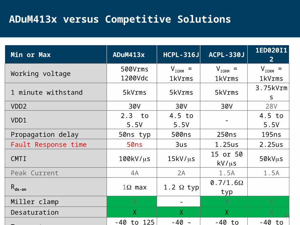
Min or Max ADuM413x HCPL-316J ACPL-330J 1ED020I12
Working voltage 500Vrms1200Vdc
VIORM = 1kVrms
VIORM = 1kVrms VIORM = 1kVrms
1 minute withstand 5kVrms 5kVrms 5kVrms 3.75kVrmsVDD2 30V 30V 30V 28VVDD1 2.3 to 5.5V 4.5 to 5.5V - 4.5 to 5.5VPropagation delay 50ns typ 500ns 250ns 195nsFault Response time 50ns 3us 1.25us 2.25usCMTI 100kV/ms 15kV/ms 15 or 50 kV/ms 50kVmsPeak Current 4A 2A 1.5A 1.5ARds-on 1W max 1.2 W typ 0.7/1.6W typMiller clamp X - X X
Desaturation X X X XTemperature range -40 to 125 C -40 – 100C -40 to 105C -40 to 105C
Split Output X - - -
ADuM413x versus Competitive Solutions
23
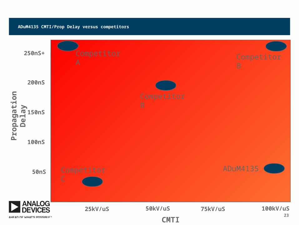
ADuM4135 CMTI/Prop Delay versus competitors
50nS
100nS
150nS
200nS
250nS+
25kV/uS 50kV/uS 75kV/uS 100kV/uS
ADuM4135
Competitor B
Competitor B
Competitor A
CMTI
Prop
agat
ion
Del
ay
Competitor C