isokern® epa qualified® fireplace manuals/2009-11-12-epa-web.pdfchimney system is tested and...
TRANSCRIPT
©2007EarthcoreIndustries,L.L.C.
THIS MANUAL CAN ONLY BE REPRODUCED IN ITS ENTIRETY
Isokern® EPA Qualified® FireplaceInstallation, Operation, Maintenance and Owner’s Manual
Model 36 CA PRODUCT OF EARTHCORE INDUSTRIES, LLC.
Important:Thismanualcontainsassemblyrules,installationsteps,guidelines,useandmaintenanceinstruc-tions for the Standard EPA qualified system. This manual must become the property of and be reviewed by allcurrentandfutureusersofthisproduct.Itistheresponsibilityofthegeneralcontractorandtheinstallerof this product to ensure that the instructions in this manual are followed exactly and, further that any al-lowed gas log appliance used in this product be installed in strict accordance with NFPA 58, NFPA 54/ANSI Z223.1 and the gas log manufacturer’s explicit installation, sizing and operation instructions. It is the responsibility of the general contractor to provide adequate clearances from all firebox surfaces as specified inthismanual.
INSTALLER: Leave this manual with the applianceCONSUMER: Retain this manual for future reference
InstallationDate______________________________
NOTE: The Catalytic Combustor system should be replaced at a minimum in 3 years, maximum of 5 years.
Be Sure to Read Entire Manual Before Beginning Construction.Contents of this manual may change without prior notification.
THIS FIREPLACE IS DESIGNED for USE withSOLID WOOD LOGS, PLUMBED PROPANE
(LP) or NATURAL GAS (NG), ONLYWARNING: If the information in this manual is not followed exactly, a fire or explosion mayresult causing property damage, personal injury or loss of life.
SBCCI NO. 9626 NYC-MEA 241-90-EICC Report NO. ESR-2316 LA RR NO. 25483IBC 2006, IRC 2006, IMC 2006 Issued: February, 2010 Revision: 003
INTERTEK TESTING SERVICES REPORT NO. 3159656MID-008OMNI-TEST LABORATORIES REPORT NO. 257-F-06-3

TABLE OF CONTENTSGeneral Information .......................................................................................................................................Intended Use Statement ......................................................................................................................................SafetyInstructions..............................................................................................................................................Warnock-HerseyListingLabelandEPAHangtag.............................................................................................Assembled Firebox & Smoke Dome Dimensions .............................................................................................. Component List & Dimensions .......................................................................................................................... Required Clearance to Combustibles ................................................................................................................. Assembly Instructions 36 C ......................................................................................................................... Access Modification ..........................................................................................................................................Firebrick Installation ..........................................................................................................................................Summary.............................................................................................................................................................CatalyticCombustorWarranty............................................................................................................................Fireplace Waranty.................................................................................................................................................
345678910-13141516-171819
2

General Information
The Standard EPA qualified fireplace system is a prefabricated, refractory modular fireplace and chimney system designed for field assembly. The system consists of interlocking precast parts which are glued together with a masonry adhe-sive. The parts of the Standard EPA qualified fireplace system and DM 54 chimney system are precast using a pro-prietary mixture of volcanic pumice aggregate and cement. Itincludesallthepartsnecessaryforassemblyofacompletefirebox, smoke dome and chimney system. Each Standard EPA qualified fireplace component is designed for a specific part of the fireplace such that only one meansforassemblyispossible. The EPA qualified model requires an in-line or chimneytopdamper. The Standard EPA qualified fireplace system requires a Standard EPA qualified refractory fire brick liner be applied to the interior of the firebox. Fire brick must be a minimum thick-ness of one and one-eighth inch (1-1/8”). The Standard EPA qualified fireplace system is avail-able in one size: thirty-six inch (36”). This unit has a thirty inch (32”) rough opening height before fire brick. The DM 54 chimney system is a dual module refrac-torychimneysystem.Thebasicchimneyconsistsofanoutercasing block and an inner liner with a fourteen inch (14”) di-ameter flue hole. The chimney components are field assembled using Earthcore Mortar to glue the components together. The DM 54 chimney system also includes an offset chimney block component, used to create offsets to the verti-cal run of the chimney. A brickledge component is available, designed to support chimney top brick veneer finishes.Prefabricated masonry chimney termination caps are also avail-able. The various Standard EPA qualified fireplace system components will be described and illustrated in the follow-ingpages.Closeattentionshouldbepaidtoeachcomponentgroup’s specifications and installation requirements as de-scribedinthismanual.
Important: Due to heat and weight issues, the Standard EPA qualified fireplace installations require that the system be built upon a non-combustible concrete slab with no wood underpin-nings supported to footings with concrete or steel and designed to carry the total weight of the Isokern fireplace and chimney system. The Fire-Lite application of the Standard EPA quali-fied fireplace fireplace is designed to be built upon a combusti-ble floor system and will also require a design that will support the total weight of the Isokern fireplace and chimney system. The FTF-13 or equivalent chimney system only must be used with the Fire-Lite application. Chimney system installations over 57’ - 0” will require additionalsupport.
3

Intended Use Statement
Note: Do not scale drawings. Illustrations in this manual are not to scale and are intended to show “typical” installations. Nominal dimensions are given for design and framing reference only, since actual installations may vary due to job specific design preferences. Always maintain the statedminimumclearancestocombustiblematerials.Donot violate any specific installation requirements. The Standard EPA qualified fireplace and DM 54 chimneysystemistestedandlistedbyWarnockHersey(In-tertek Testing Service) - Report No. 315965MID-008 and Report No.315986MID-006 - to UL 127, and UL 103HT - 2006. The EPA qualifying emissions tests were conducted by OMNI-Test Laboratories Report No.: 257-F-06-3. Standard EPA qualified fireplace systems are also designed for installation in accordance with the National Fire Protection Association Standard for chimneys, fireplac-es, vents and Solid Fuel-Burning Appliances (NFPA 211). Standard EPA qualified fireplaces are not listed for use with fireplace inserts.
4
Intended Product Use Statement: The Standard EPA qualified fireplace and DM 54 chimney systems are intended to burn solid wood fuel, propane ornaturalgas.Note: Installation of a gas pipe must comply with the Stan-dard for Decorative Gas Appliances for Installation in Vented Fireplaces, ANSI Z21.60. This fireplace is not designed to sit directly on a com-bustible floor system. The Fire-Lite application is designed to sit on a combustible floor. This fireplace is intended for use as a supplemental heat source only and is not intended for heavy useasaprimaryheatingsystem. Overfiring, abusive burning or mistreatment will void anyclaims(eg.burningconstructiondebrisorotherhighlyflammable material; tossing, kicking or otherwise forcing logs into the firebox). Standard EPA qualified fireplace and DM 54 chimney systems are conventional indoor or outdoor fireplaces designed to appear like traditional masonry fireplaces. Standard EPA qualified fireplace and DM 54 chimney system units are in-tendedforinstallationinresidentialhomesandotherbuildingsof conventional construction.
Note: The local authority having code jurisdiction should be consultedbeforeinstallationtodeterminetheneedtoobtainapermit. Important areas of concern with the installation ofthese fireplaces are: construction of proper load bearing foun-dation and concrete support slab; code required hearth exten-sion substrates and supports; proper assembly of components; clearance to combustible materials; height of chimney; and, techniques employed in applying finishing materials to the fireplace opening and hearth extension. Each of these important topics will be covered in detail throughout this manual. Installation personnel must give specialattentiontoeachtopicastheinstallationprogresses. All work performed on, near and adjoining the fireplace and chimney installation must meet or exceed the specifications and requirements in this manual and the prevailing local building code. Subsequent renovations, additions of cabinets and storage spaces in the enclosure surrounding the fireplace are also limited to the specifications in this manual and to the prevailing local building code. Isokern is not responsible for other construction work around the fireplace unit.WARNING: This fireplace has not been tested for use with glass doors. To reduce the risk of fire or injury, do not install glass doors. Some jursdictions require the use of glass doors. If glass doors are used, operate fireplace with doors in the fully open position.
1. Before starting the Standard EPA qualified fireplace and DM 54 chimney installation, read these installation instructionscarefully to be sure you understand them completely. Failure to follow them could cause fireplace malfunction resulting in serious injuryorpropertydamage.2. Always check local building codes governing fireplaces and fireplace installations. The Standard EPA qualified fireplace and DM chimney installation must comply with all local, regional, stateandnationalcodesandregulations.3. Standard EPA qualified fireplace and DM 54 chimney sys-tems are intended for use in any application where a traditional masonry type fireplace would apply. The chimney system must always vent vertically to the outside of the building.4. Creosote and soot formation and the need for removal: When wood is burned slowly, it produces tar and other organic vapors which combine with expelled moisture to form creosote. The creosote vapors condense in the relatively cool chimney flue of a slow burning fire. As a result, creosote residue accumulates on the flue lining. When ignited this creosote makes an extremely hot fire. Becauseofcreosoteandsootbuildupitisnecessarytoinspect and clean the fireplace and chimney prior to use and peri-odically during the heating season. Cleaning of the fireplace and thechimneysystemshouldbedoneannuallyataminimum.Incolderclimates,chimneycleaningmayneedtobedoneperiodi-callythroughouttheheatingseason.5. Before servicing, allow the fireplace to cool. Always shut off any electricity or gas to the fireplace while working on it. 6. Use only solid fuel or natural or LP gas log sets in this unit. Do not use artificial wax based logs, chemical chimney cleaners or flame colorants in this fireplace.7. Never use gasoline, kerosene, gasoline-type lantern fuel, charcoal lighter fluid, or similar liquids to start or “freshen up” a fire in this fireplace. Keep all flammable liquids at a safe distance from the fireplace.8. Always keep the flue damper open when heat is present in the fireplace.9. Do not use a fireplace insert or any other product not speci-fied for use with the Standard EPA qualified fireplace and DM 54 chimney systems unless written authorization is given by Isokern. Failure to heed this warning may cause a fire hazard and will void the Isokern warranty.10. This fireplace is not intended to heat an entire home or to be used as a primary heat source. It is designed to ensure homeown-er comfort by providing supplemental heat to the room.11. Always ensure that an adequate supply of replacement com-bustion air from the outside of the house is accessible to the fire to support normal combustion. Fireplaces consume large volumes of air during the normal firing process. In the event the home is tightly sealed and has modern energy efficient features, the optional combustion air supply kits may not provide all the air required to support combustion and the proper flow of combustion gases up the chimney.
Themanufacturerisnotresponsibleforanysmok-ingorrelatedproblemsthatmayresultfromthelackofadequate air supply flowing into the house. It is the respon-sibility of the builder/contractor to ensure that adequate air supply has been provided for the fireplace.12. “Smoke free” operation is not warranted nor is the manufacturerresponsibleforinadequatesystemdraftcausedbymechanicalsystems,generalconstructionconditions,inadequate chimney heights, adverse wind conditions or any unusual environmental conditions or factors beyond the manufacturer’s control.
Caution: When used with the Standard EPA qualified fireplace system, all gas log sets must be operated with the damperclampedinthefullyopenposition.Thisincludesunlisted “vent free” log sets. Only listed “vent free” log sets may be operated with the damper in the closed position.
13. When in doubt about a component’s usability - has vis-ibleorsuspectedphysicaldamage-consultyourIsokerndistributor or authorized Isokern representative for advice.14. Modification to STANDARD components not men-tioned in this manual may void claims, listings and approv-alsandcouldresultinanunsafeandpotentiallydangerousinstallation. Alterations to the STANDARD firebox are allowed with prior written approval and instructions from Earthcore Industries, LLC. The installer indemnifies the manufacturer of all claims and under no circumstances will manufacturer be liable for consequential, incidental, indirect, punitive or other damages of any kind or nature, whether foreseeable or not, based on any claim by any party as to the modifications of the Isokern fireplaces.15. Wherever insulation is used, the Standard EPA quali-fied fireplace must not be placed directly against it. Keep all insulation or vapor barriers a minimum of three inches (3”) away from all fireplace and chimney components.It is recommended that insulation and vapor barriers, if used, first be covered with gypsum board, plywood, particle board or other material to assure that insulation and vapor barriersremaininplace.
WARNING: Do not pack required air spaces with insulationorothermaterials.
16. Never leave children unattended when there is a fire burning in the fireplace.17. Burning some fuels (such as charcoal) can be hazard-ous due to the possibility of producing carbon monoxide, a colorless, odorless gas. Early signs of carbon monoxide poisoning resemble flu symptoms, including headaches, dizziness or nausea. Over exposure to carbon monoxide canleadtoillnessanddeath.Itisstronglyrecommendedtoinstall smoke and carbon monoxide alarm / detector devices wherever fireplaces are in use.
5
SafetyInstructions

WarnockHerseyListingLabel- Facsimile -
6
Isokern Fireplace and Chimney Systems are tested and listed to UL standards: UL 127, ULC S610, and UL 103HT. The listing label shown above outlines the listed clearances to combustibles and indicates that the units are suitable for use with solid fuel or listed gas appliances. Refer to the manufacturer’s installation manual for detailed description of clearances to combustibles and all other installation information. A metal listing label similar to that shown above is affixed to each Standard EPA qualified fireplace. Do not remove the listing label from the Standard EPA qualified fireplace fireplace. In addition, an EPA qualifying label will be affixed to the Catalytic Combustor system. Keep this label in a safe place if needed for permits or building inspection. Prior to beginning installation, contact your local building official to determine the need to obtain a permit.
MANUFACTURER: EARTHCORE INDUSTRIES, LLC
MODEL NO: Series 36 C PARTICLE EMISSIONS: 2.93 GRAMS/KG OF WOOD BURNED
For proper operation, catalyst must be replaced every 3 to 5 years.
FIREPLACE SMOKE EMISSIONS RANGE
Higher EmissionsLower Emissions0 12.0
THIS MODELEPA PHASE 2 EMISSIONS LEVEL2.93 5.1
Better Worse
U.S. Environmental Protection Agency Wood-burning Fireplace Program
Phase 2 Qualified models are cleaner and pollute less than those models that have not met this emissions level. Exposure to smoke has been associated with respiratory illness and other health problems. Models that have lower smoke emissions may reduce your risk.
PHASE 2 QUALIFIED
For more information go to www.epa.gov/burnwise
Fireplaces with lower emissions produce less smoke when installed and operated properly.
* EPA has determined, based on testing by an accredited independent laboratory and a certificationof conformity by a nationally recognized certification body, that this model qualifies at the Phase 2 emissions level for U.S. EPA's Voluntary Fireplace Program.
EPA Yellow Qualifying Hangtag
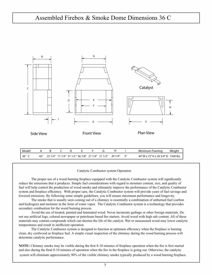
Assembled Firebox & Smoke Dome Dimensions 36 C
7
Side View Front View Plan View
Catalyst
A
E
F
E
G
H
C
D
B
Model A B C D E F G H I Minimum Framing Weight
36” C 43” 25 1/4” 71 1/4” 31 1/2 ” 36 1/8” 27 1/4” 21 1/2” 20 1/4” 5“ 44” W x 72” H x 26 3/4” D 1500 lbs.
I
CatalyticCombustorsystemOperation
The proper use of a wood burning fireplace equipped with the Catalytic Combustor system will significantly reduce the emissions that it produces. Simple fuel considerations with regard to moisture content, size, and quality of fuel will help control the production of wood smoke and ultimately improve the performance of the Catalytic Combustor system and fireplace efficiency. With proper care, the Catalytic Combustor system will provide years of fuel savings and lowered emissions. By following some simple guidelines, you will ensure maximum performance and longevity. Thesmokethatisusuallyseencomingoutofachimneyisessentiallyacombinationofunburnedfuel(carbonand hydrogen) and moisture in the form of water vapor. The Catalytic Combustor system is a technology that provides secondary combustion for the wood burning process. Avoid the use of treated, painted and laminated wood. Never incinerate garbage or other foreign materials. Do not use artificial logs, colored newspaper or petroleum based fire starters. Avoid wood with high salt content. All of these materials may contain compounds which can shorten the life of the catalyst. Wet or unseasoned wood may lower catalytic temperatures and result in inefficient operation. The Catalytic Combustor system is designed to function at optimum efficiency when the fireplace is burning clean, dry cordwood as fireplace fuel. A simple visual inspection of the chimney during the wood burning process will determinecatalyticperformance.
NOTE: Chimney smoke may be visible during the first 8-10 minutes of fireplace operation when the fire is first started and also during the final 8-10 minutes of operation when the fire in the fireplace is going out. Otherwise, the catalytic system will eliminate approximately 90% of the visible chimney smoke typically produced by a wood burning fireplace.

Component List & Dimensions 36 C
8
Isokern reserves the right to make changes at any time, without notice in design, materials and specifications and also to discontinue styles and products. Please call (800) 642-2920 for an Isokern dealer near you.
Base PlatePart No. Model QtyNo.21 36 1
Model A36 43”
Smoke Dome - Small
Part No. Model QtyNo.12 36 2
Smoke Dome - Medium
Part No. Model QtyNo.11 46 2
Side WallPart No. Model QtyNo.20 36 6
Back WallsPart No. Model QtyNo.25 36 3
Model A36 26 3/4”
Smoke Dome - Sidewall
Part No. Model QtyNo.34 36 4
A25 1/2”
3”
4”
16”32 1/2”
4”
16”43”
10 5/8”
25 1/4”
10 5/8”
5”
A
25 1/4”
16”
3”
Catalytic FilterPart No. Model QtyNo.CCB-S 36 1
Catalytic Filter Brackets (2)
25 ¼”10 ¾”
22 ½”
4”
Top Plate SmallPart No. Model QtyNo.36 36” W 1

Required Clearance to Combustibles
9
The Standard EPA qualified fireplace fireplace and DM 54 chimney system is tested and listed for installation with “clear-ance to combustibles” as follows: A: Four inch (4”) clearance to the combustible floor; B: One and one-half inches (1 1/2”) clearance at the Isokern firebox and smoke dome sides and front ; C: One and one half inches (1-1/2”) clearance at the Isokern firebox and smoke dome back wall ; D: Zero inch (0”) Clearance to the DM chimney system. Contact metal pipe manufacturer for specific clearance information
CAUTION: Maintain three inches (3”) clearance to insulation and vapor barriers from all firebox, smoke dome flue components. Note: “Combustibles” are defined as “normal construction materials” and are considered to be: wood framing materials, particle board, mill board, plywood sub-flooring, plywood paneling and wood flooring. Sheathing materials, such as plywood, particle board and drywall may cover the smoke dome front at 0” clearance. All combustible sheathing materials that protrude beyond front of firebox must be held 8” away from the sides of the fire-box opening and 8” above the top of the firebox opening. Drywall must be cut 2” back from the firebox opening sides and 8” above thetopoftheopening.
Notes: A. The Standard EPA qualified fireplace fireplace is rated for installation on a combustible floor system when using the Fire-Lite application only. The Standard EPA qualified fireplace must sit upon a concrete support slab designed to bear the total installed weight of the fireplace and DM 54 chimney system. These support slabs can have no wood underpinnings. B. Concrete support slabs for the Standard EPA qualified fireplace must provide the noncombustible hearth extension substrate needed to support the code required noncombustible hearth extension finish materials. C. All Standard EPA qualified fireplaces shall have hearth extensions of approved noncombustible material such as brick, tile, or stone that is properly supported and with no combustible material against the underside thereof. Wooden forms used during the construction of hearths and hearth extensions shall be removed when the construction is complete. D. If a raised fireplace floor and raised hearth extension are preferred, the raised underlying structure must be built of non-combustiblematerialandmustsitonnoncombustiblesubstrate.
B
A
B
B
DD D
C
Non-CombustibleFloor System
(non-insulation)
Hearth Extension(non-combustible)

10
General Isokern Assembly Instructions:
Earthcore Mortar (a thin-set type masonry adhesive) is used to glue all Isokern components together during field assembly of the unit. The mortar is supplied dry, in either 15 pound or 50 poundpails. Earthcore mortar is mixed with clean water to a smooth, workable texture (without lumps or dry pockets) of a “toothpaste” consistency. This mixture is suitable for application onto Isokern components by using a masonry grout bag supplied with the unit. Attention should be paid that the mortar mixture is not too thin or runny, as this will not allow the mortar to reach its maximum bondingstrength. Earthcore mortar is squeezed from a grout bag onto the contact surfaces of the Isokern components as they are fitted together. It is important that a 1/2” bead of mortar on all the compo-nents’ contact surfaces is applied at about 1/2” in from all edges of thecontactsurfaceofthecomponent. When setting the next component onto the mortared con-tact surface of the first component, some mortar should squeeze out alongthefaceoftheentirejointasasignofcompleteandpropersealingofthejoint. On broader contact surfaces it is advisable to apply several additional 1/2” beads of the Earthcore Mortar to the area to assure propersealingofthejoint. Properly mortared firebox and smoke dome assembly re-quires approximately 25 pounds (dry measure) of Earthcore mortar.
Broken Components: Components broken into 2 or 3 pieces can be repaired by usingEarthcoremortaralongthebreaklineasthecomponentissetintoplace.Componentsbrokenintomultiplesmallpiecesshouldbediscardedandreplaced.
Leveling and Aligning Components: Be sure to assemble all Isokern components level and flush with adjoining components. Earthcoremortarisnotintendedtocreateamortarjointof any thickness for leveling purposes. Therefore, leveling and alignmentadjustmentsaremadebytheuseofsmallplasticshimssupplied with the unit. The shims can be inserted under a component to level and align it with adjacent Isokern components. Be sure to re-grout any andallgapsresultingfromshiminsertiontomaintaincomponentstofullbearing.
Notes: 1. Do not mix Earthcore mortar with spirits or anti-freeze agents. 2. The maximum recommended mortar joint thickness at Isokern components is 1/4”.
3. Earthcore mortar can be troweled over the face of a joint where it has squeezed out while setting components. It is not intended that the exposed faces of the Isokern components be completely covered with the mortar.
Assembly Instructions - 36 C
Earthcore Mortar
Shim if requiredto acheive correct height

Installation:Step 1: Set the Standard EPA qualified fireplace base plate in a full bed of Earthcore Mortar flat on a proper concrete support foundation. Do not set the base plate so that it is in span. Level the base plate by floating it in a bed of Earthcore Mortar to full bearingagainsttheunderlyingnoncombustiblesupportsurface.
Note: The bottom of the sidewall has a slightly smaller opening than does the top (meaning when the sidewalls are made – the board side of the sidewall has about a 1/8” narrower opening than does the top. If the fireplace is stacked where the top sidewall is placed upside down the clip will have a slight interference when attempting to install. If this occurs, scrape away an area about 1.5” wide by the 1/8”.
Note: If the design preference is for a “flush hearth” (fireplace floor flush with the room’s floor), the base plate can be omitted from the assembly and the firebox walls built directly on the concrete support slab. The fire brick floor of the firebox is then set directly to the concrete support slab. This makes the fireplace finished fire brick floor approximately one and one-half inches (1-1/2”) above the top of the concrete support slab. If the design preference is for a raised hearth (floor of the fireplace elevated above the room’s floor), then the base plate canbesetonanoncombustibleplatformthatisbuiltuptothedesiredraisedhearthheightontheconcretesupportslab. When calculating raised hearth height be sure to allow for the three inch (3”) thick base plate plus the one and one half inch (1-1/2”) thick fire brick floor in addition to the height of the platform. Whether a flush hearth is preferred or a raised hearth, the combustible floor on front of the fireplace must be covered with a noncombustible hearth extension set tight against the fire-place front and extending at least 20 inches out from the finished fireplace and at least 12 inches beyond the finished sides of the fireplace opening. For all “raised hearth” construction where concreteblocksareusedtocreatetheraisedplatform,itisnecessarytousethebaseplate.Besuretomortartheconcreteblockplat-form together. CMU used for base plate support should be rated ASTM 90.
Assembly Instructions - 36 C
11
Raised hearthfor wood or
concrete installs
Flush Hearthon Concrete
Foundations Only
EarthcoreMortar

Assembly Instructions - 36 C
Step 2: Set the first course of the firebox back wall and side walls into place. It may be convenient to dry set the first course of side wall and back wall into place on the Isokern base plate and then to trace their position on the base plate with a pencil. After outlining the dry set pieces, remove them and apply Earthcore Mortar to the areas traced on the base plate where the side walls and back wall are to sit. By doing this, the first layer of wall components can be set directly into mortar alreadyappliedtotheproperareasonthebaseplate. Be sure to put Earthcore Mortar on the contact surfaces of the vertical joints where the side wall and back wall componentsconnect.
Step 3: Continue assembly of the second, third and fourth courses of the firebox side wall and back wall. Apply mortar to the top of each layer of wall components, set the next course above into place. Be sure to mortar all vertical joints of the side wall to back wall connection when setting each component to itsmate. Look for some mortar to squeeze out along the joints ofallcontactsurfacesasasignthatthejointisthoroughlysealed with the approved mortar.
Step 4: When all of the firebox wall components are set, check the top surface of the firebox for level.If necessary, adjust the top surface of the box assembly for level by inserting a shim between the lowest wall component and the topsurfaceofthebaseplate. Any gap created under the wall components during the Shim leveling process must be filled with mortar to full bearing againstthebaseplate.
Step 5: Make sure that the firebox assembly has been set level and square. Adjust as required while the mortar is still wet. Make a final inspection of all contact joints in the fire-box assembly to be sure they are properly sealed. Fill any and all gaps in the assembly, as necessary, with the approved mortar.
Step 6: Take the Catalytic assembly out of the box and verify all components are in tact and Yellow EPA hangtag is attached to thecombustor.TheCatalytickitshouldcontainaCatalyticCombustor, and two (2) metal angle support brackets.
Note: Remove hangtag from combustor and place in a secure, permanent location. Retention of this hangtag by the owner of the fireplace is mandatory. If ownership changes, hangtag should be given to the new homeowner.
Step7:Insertsupportbracketssothatthelargestangledportionslides into the side wall cavity toard the front of the sidewall slots. The smaller angles should be facing upward toward the inside of the firebox.
12
EarthcoreMortar
Earthcore Mortar
First CourseBack Wall
Top CourseBack Wall
Earthcore Mortar

13
Assembly Instructions - 36 C
Step 8: Center the Catalytic Combustor in the firebox andrestitontopofthesupportbracketsmakingsurethat the filter is equally settled on the brackets. The filter should be set toward the rear of the firebox.
Step 9: If grouting the inside of the sidewalls, leave the top1 3/4” without grout or else measure and locate the mounting clip to the exact dimension (based on the thickness of the brick & mortar used to line the inside of the firebox backwall).
Step 10: Set the back smoke dome component across the rear side walls in a bed of mortar and flush with the back face of the back wall. Setthefrontsmokedomecomponentinmortaracross the front side walls flush with the front of the sidewalls.
Step 11: Position the smoke dome’s sloping sidewalls at eachendofthesmokedomecomponents. The sloping sidewalls fit in between the front and rear smoke dome components and also fit into the haunchesattheendsofthefrontandrearsmokedomecomponents. Mortar all contact surfaces thoroughly.
Note: The smoke dome sloping sidewalls have a beveled bottom edge so that they will sit tight onto the flat top of the side walls.
Step 12: Make sure that all component contact surfaces have been properly sealed with approved mortar. Check smoke dome front and back walls to see that they are plumb, level and in alignment with mating components. Checkalignmentofthesmokedomeslopingsidewall components to see that they are fully seated.
Step 13: Set the smoke dome top plate into position on top of the smoke dome wall assembly. One side of the smoke dome top plate shows a thickenedcenter.Thissideisthebottomfaceofthetopplate. The fourteen inch (14”) diameter flue hole in thetopplateiscenteredinthesmokedomefromsidetosidebutisoffsetfromfronttoback. Make sure that the top plate is set so that the flue hole is closer to the back wall of the smoke dome assembly. Be sure to set the smoke dome top plate flush with the front, back and sides of the smoke dome assem-bly. All contact surfaces must be properly sealed with the approved mortar.
Note:Thecompletedsmokedomeassemblyshouldpresent a stable and level surface for setting the flue components.
14
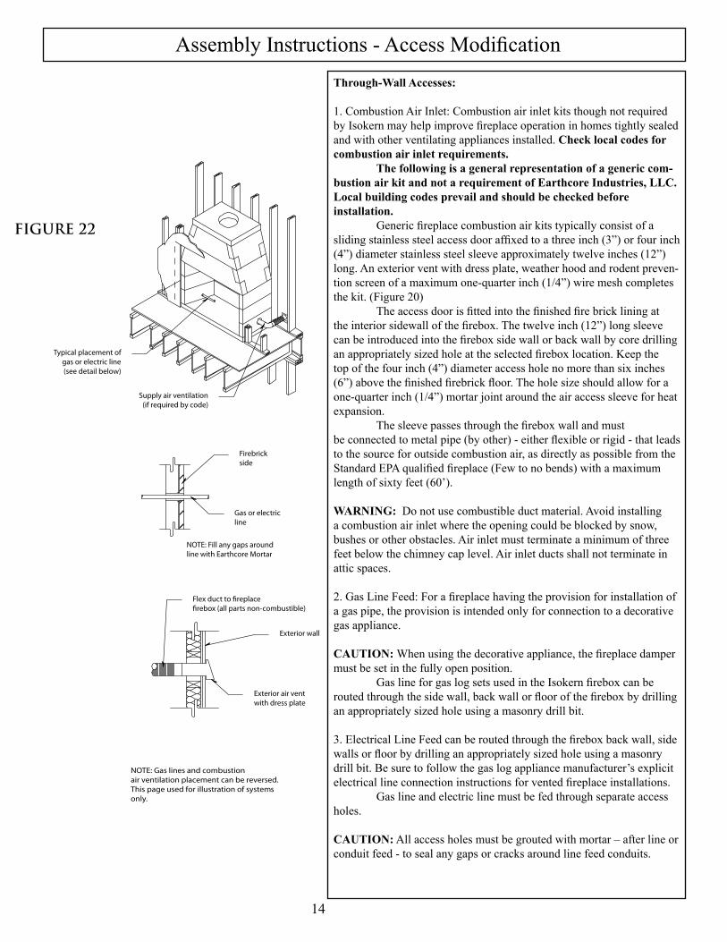
Assembly Instructions - Access ModificationThrough-Wall Accesses:
1. Combustion Air Inlet: Combustion air inlet kits though not required by Isokern may help improve fireplace operation in homes tightly sealed and with other ventilating appliances installed. Check local codes for combustion air inlet requirements. The following is a general representation of a generic com-bustion air kit and not a requirement of Earthcore Industries, LLC. Local building codes prevail and should be checked before installation. Generic fireplace combustion air kits typically consist of a sliding stainless steel access door affixed to a three inch (3”) or four inch (4”) diameter stainless steel sleeve approximately twelve inches (12”) long. An exterior vent with dress plate, weather hood and rodent preven-tion screen of a maximum one-quarter inch (1/4”) wire mesh completes the kit. (Figure 20) The access door is fitted into the finished fire brick lining at the interior sidewall of the firebox. The twelve inch (12”) long sleeve can be introduced into the firebox side wall or back wall by core drilling an appropriately sized hole at the selected firebox location. Keep the top of the four inch (4”) diameter access hole no more than six inches (6”) above the finished firebrick floor. The hole size should allow for a one-quarter inch (1/4”) mortar joint around the air access sleeve for heat expansion. The sleeve passes through the firebox wall and mustbe connected to metal pipe (by other) - either flexible or rigid - that leads tothesourceforoutsidecombustionair,asdirectlyaspossiblefromtheStandard EPA qualified fireplace (Few to no bends) with a maximum length of sixty feet (60’).
WARNING: Do not use combustible duct material. Avoid installing a combustion air inlet where the opening could be blocked by snow, bushesorotherobstacles.Airinletmustterminateaminimumofthreefeet below the chimney cap level. Air inlet ducts shall not terminate in atticspaces.
2. Gas Line Feed: For a fireplace having the provision for installation of a gas pipe, the provision is intended only for connection to a decorative gasappliance.
CAUTION: When using the decorative appliance, the fireplace damper mustbesetinthefullyopenposition. Gas line for gas log sets used in the Isokern firebox can be routed through the side wall, back wall or floor of the firebox by drilling an appropriately sized hole using a masonry drill bit.
3. Electrical Line Feed can be routed through the firebox back wall, side walls or floor by drilling an appropriately sized hole using a masonry drill bit. Be sure to follow the gas log appliance manufacturer’s explicit electrical line connection instructions for vented fireplace installations. Gas line and electric line must be fed through separate access holes.
CAUTION: All access holes must be grouted with mortar – after line or conduitfeed-tosealanygapsorcracksaroundlinefeedconduits.
FIGURE 22
Firebrickside
Gas or electricline
NOTE: Fill any gaps aroundline with Earthcore Mortar
Flex duct to fireplacefirebox (all parts non-combustible)
Exterior wall
Exterior air ventwith dress plate
Supply air ventilation(if required by code)
Typical placement ofgas or electric line(see detail below)
NOTE: Gas lines and combustionair ventilation placement can be reversed.This page used for illustration of systemsonly.

15
Assembly Instructions - Fire Brick Installation
Fire Brick Installation:
ThemanufacturerrequiresthattheStandardEPAqualified firebox be lined with a minimum one and one-eighth (1-1/8”) thick rated fire brick. The pattern for the fire brick lin-ing is an owner option. Standard N-Type brick mortar is a suit-able fire brick mortar for the Standard EPA qualified fireplace and good masonry practices should be followed. All required through-wall accesses (gas and electrical line feeds and combustion air supply access holes) should be drilled before the required fire brick lining is installed. It takes a total of about five gallons of N-Type brick mortar mix (dry measure) to fire brick line a fireplace. Face joints of one quarter inch (1/4”) to three-eightsinch (3/8”) give a good appearance to the finished brickwork however, this is just a suggestion and other face joint dimensionsarealsoacceptable.
Step 1. Wet mop the inside of the Standard EPA qualified fireplace with a damp sponge to remove dust and loose particles from the interior before installing fire brick.
Step 2. Start the fire brick at the front edge of the floor of the Isokern firebox, proceeding inward toward the back.
HINT: Dip each firebrick into water before applying.
Step 3. Next, apply fire brick to the back wall of the unit start-ing at the bottom of the back wall and working upward to the top of the back wall.
Step 4. Finally, set the side wall fire brick by starting at the front edge of the unit’s side wall and working inward toward the back wall fire brick.
Isokern makes no claims as to the performance of fire brick or fire brick mortar(s). It is typical for heat stress cracks to appear in the fire bricks in wood burning fireplaces.
ExpansionGap(Both Sides)
Firebrick Floorand Backwall(Built First)
Firebrick Floorand Backwall(Built First)

16
Summary
1.WARNING: Fireplace and chimney systems will only draught prop-erly when they are installed according to the instructions, in an appropriate location and with the proper chimney height. Install-ing the fireplace according to the instructions, choosing an ap-propriatelocation,andchoosinganappropriatechimneyheightaretheresponsibilityofthedesignerandthebuildingcontractor. Tightly insulated and sealed homes, two story interior spaces and high vaulted ceilings can cause negative air pressures within the house which can impair drafting performance. HVAC return air ducts near the fireplace opening will adversely affect the fireplace drafting performance. Itistheresponsibilityofthedesigner,thebuildingcontractorandtheirmechanicalcontractortodeterminethatthebuilding’s internal air pressures are conducive to positive fire-placedrafting. Avoid placing any fireplace in an area near tall trees, tall buildings,orhighlandmasses.Thesestructurescanreduceam-bient air flow pressure as well as produce down draughts, either of which can impair fireplace drafting performance. Earthcore Industries L.L.C. does not warrant drafting andisnotresponsibleforit.
2. Standard EPA qualified fireplace and Fire-Lite Fireplace Curing Instructions: ItiscriticalthattheIsokernmasonryelementsinthefirebox and smoke dome assembly be dry before firing of the unit. Moisture left in the components from exposure during stor-age and shipping, as well as moisture from the installation phase, mustbeeliminatedbeforetheunitisputtoitsintendeduse. The first step in reducing the ambient moisture is to be sure that the completed fireplace rest totally in a dried-in setting for a minimum of 28 days after construction of the unit is com-plete. The next step in curing the fireplace is to be sure that the first five or six fires are of short duration. The first fire of the unit can take place once the mini-mum twenty-eight day drying period has passed. This fire should beespeciallyshort. Start the first fire slowly with a small amount of paper and kindling (small dry wood splits or twigs) and a maximum load of four to six pounds of dry firewood, estimated to be no more than two or three logs each of about three inches (3”) to four inches (4”) diameter. The first fire should burn for no more than thirty to sixty minutes and then allowed to go out. Do not refuel the fireplace during the first lighting. A cooling off period of twenty-four hours, at a mini-mum, should follow the first fire. The second fire should be the same as the first fire. The second fire should burn for no more than thirty to sixty minutes and allowed to go out. Do not refuel the fireplace duringthesecondlighting.
A twenty-four hour cooling off period must be observed following second lighting.After first and second fire, continue use of the unit with three or four small fires of short duration (sixty minutes or so) and smallfuelload. After these first five or six small fires of short dura-tion normal use of the fireplace can proceed. For normal use the maximum recommended fuel load is twelve to sixteen pounds of dry firewood at a time. This fuel load is consid-ered to be approximately three to five cured hardwood logsof about three inches (3”) to six inches (6”) in diameter. As the fire burns down, refueling should be only one or two logs addedatatime.
Important:Donotburnconstructiondebrisortrashofanykind in the Fire-Lite fireplace. Whereasitisnotuncommonforconstructiondebrisand refuse to be burned in a fireplace by site personnel on a project that is under construction, this activity must be avoided. Itistheresponsibilityofthebuildingcontractortoinsurethattherequireddry-inperiodismetandthattherequired lighting sequence is performed by the owner or by the owner’s agent.
3. Log grates are required for burning solid fuel in the Isokern fireplace. Grates allow for easy air flow up through the burning logs thus creating a more complete and efficient burningofthefuel.
4. How to Build a Fire: First set the fireplace damper in the full open posi-tion. Begin laying the fire by placing several pieces of wad-deduppaperdirectlyontheloggrate.Placekindling(smallsplits of dry pine or other dry softwood) on top of the paper, enough to loosely cover the paper. Next arrange several small, dry hardwood or softwood logs or log splits on top of thekindlinglayer. Finally, arrange two or three larger hardwood logs (oak, hickory, etc.) or log splits on top of the stack.Ignitethepaperatthebottomofthestack.Theburningpaper will ignite the kindling which will, in turn, set the remaining fuel on fire. Be sure to stack all firewood in such a way that it will settle into the log grate as the paper and kindling layers are burned away. Additional logs can be set onto the fire as each fueling burns down. Ideally, fuel logs should be of a hardwood species that have been air dried for one year or longer. Use of cured or uncured pine logs and uncured hardwood logs for fuel should be avoided. Pine logs and uncured hardwood logs will tend to smolder and burn at relatively low temperatures producing high levels of soot and creosote.
Important: Do not throw, toss, jam, kick or otherwise force logs into the fireplace.

17
Summary WARNING: Never use gasoline, gasoline type lantern fuel, kero-sene, charcoal lighter fluid or other similar liquids to start or “freshen up” the fire in this fireplace or in any fireplace.
WARNING: If processed solid fuel firelogs are used: Do not poke or stir the logs while they are burning. Use only firelogs that have been evaluated for the application in fireplace and refer to firelog warnings and caution markings on packaging prior touse.
5. Avoid over-firing this fireplace. Some examples of over-firing are:a.Burningofscraplumber,constructiondebris,pinebranchesand brush or cardboard boxes;b. Burning small diameter twigs, branches or anyother small sized combustible materials in quantities which exceed the volume of the normal log fire;c. Use of artificial wax base logs, trash or other chemicals or chemicallytreatedcombustibles.
WARNING: Over-firing can permanently damage this fireplace system.
6. Fireplace Doors and Screens: This fireplace has not been tested for use with doors.To reduce the risk of fire or injury, do not install doors. If doors are required by the local authority having jurisdiction then doors must be kept in the fully open position when the fireplace is in operation. Isokern does not limit the use of fireplace screens.
7.Disposal of Ashes: It is recommended that the firebox be cleaned of ex-cessive ashes before each use. It is necessary to remove ashes from the open front of the fireplace. To do so, proceed in the following manner: Allow the fire to go out and the ashes to cool for at least six to eight hours. Afterthecoolingperiodcarefullypickuptheashesfrom the firebox with a small, metal fireplace shovel or other metal scoop and place them in a metal container with a tight fitting lid. If possible do not sweep the ashes as this will stir themintotheairanddispersethemintotheroom. Theclosedcontainerofashesshouldbeplacedona noncombustible floor or on the ground, well away from all combustible materials, pending final disposal. If the ashes are disposed of by burial in soil or otherwise locally dispersed, theyshouldberetainedintheclosedcontaineruntilallcin-ders have thoroughly cooled.8. Inspection and Cleaning: At least twice a year in warm climates or monthly duringtheheatingseasonincolderclimates,thoroughlyinspect the Fire-Lite fireplace and chimney system.
Chimneys must be installed so that access is provided for inspectionandcleaning.Thechimneyshouldbeinspectedmonthlyduringtheheatingseason. Inspect the entire flue from the top down for obstruc-tions such as birds’ nests, leaves, etc. Such obstructions must be removed. Check spark arrestor screens for clear flow of smoke every two to four weeks during the heating season.Inspect the flue periodically during the heating season for the presenceofsootandcreosotebuildup.Ifcreosoteorsoothas accumulated, it should be removed to reduce the risk of chimney fire. Have your chimney cleaned by a professional chim-ney sweep if you have doubts about your ability to do it.Use a plastic, wood or steel brush to clean the chimney.Scrub the spark arrestor/chimney cap with a wire brush.Remove any chimney cap for flue cleaning from thetop. Open the damper in the firebox for cleaning access from below. Clean the inner portion of the flue by using a flexible handledchimneycleaningbrush. For straight run flue the proper size brush can be pulled up through the flue from the firebox with the damper open. Ifthechimneyhasanoffsetchimneysection,brushcleaning from the chimney top down to the offset/return and then from the firebox up to the offset section is the proper method. In either case, cover the fireplace opening with a damp sheet (sealed to the opening with masking tape) before brush cleaning. Do not remove sheet until the soot has settled. It is advised to vacuum loosened soot. Do not sweep loosened soot as sweeping will disperse soot into the air and about the room.
WARNING: Do not use chemical fireplace and chimney cleaners that are poured on a hot fire. These can be dangerous and generally work only on the flue section nearest thefire, leaving the rest of the flue unaffected.
9. Exterior Maintenance: Annually, at a minimum, check all metal flashingsand weather seals around the exterior chimney where it penetrates the roof surface; inspect any chimney top spark arrestors, metal cowlings and weather hoods to make sure they are secure and weather tight. Seal any cracks or gaps in chimney-to-roof flashings to prevent possible roof and chimney chase leaks.Inspectanycementchimneycaporclaychimneypotterminations to make sure they are not diverting water into the structure.Sealanysuspectedcracksorgapsinthesemasonrycomponents.

CatalyticCombustorWarranty
18
Clear Skies warranty obligations for the HearthCAT Emissions Control System are limited to the terms set forth below: Clear Skies Unlimited, Inc. (“Clear Skies”) warrants to the consumer who purchases a new solid fuel burning fireplace containing a HearthCAT Emission Control System as a new component, to replace the catalyst at no charge should it cease to function within three years from the date of purchase. The HearthCAT Catalytic Component is designed to perform efficiently for three years of fireplace operation. ONLY recommended fuels should be burned. Follow the fueling directions in manufacturers operating manual. For warranty purposes, proof of fireplace or HearthCAT™ purchase is required. Labor for removal and/or re-installation of the catalytic component is not the responsibility of the manufacturer.
This warranty applies only to CS-100 Series HearthCAT™ catalytic components manufactured by Clear Skies Unlimited Inc. For replacement of a Clear Skies catalytic combustor under the conditions of this warranty, please contact the manufacturer @ www.clearskiesunlimited.com
NEITHER CLEAR SKIES UNLIMITED INC. NOR THE DEALER WHO SELLS THE HEARTHCAT™ EMISSION CONTROL SYSTEM IS RESPONSIBLE FOR INDIRECT, INCIDENTAL, SPECIAL, PUNITIVE OR CONSEQUENTIAL DAMAGES ARISING OUT OF THE IMPROPER USE OF THIS PRODUCT OR THE CONTINUED USE OF THIS PRODUCT BEYOUND THE REQUIRED REPLACEMENT PERIOD.

Warranty & Disclaimer
Isokern FIreplace
ISOKERN offers a lifetime warranty for all Isokern components, to be free from defects in materials that negatively affect system performance from the date of purchase, subject to the terms and conditions of this limited warranty.
This warranty covers only the above stated components, and NO WARRANTY, EXPRESS OR IMPLIED,EXTENDS TO ANY OF THE HARDWARE, FOOTING, VENTS, DUCTING, METAL FLUES, FIRE BRICK OR ACCESSORIES. THIS WARRANTY DOES NOT COVER DRAFTING, SMOKING OR PUFFING OF THE FIREPLACE SYSTEM. Factors beyond the manufacturer's control affect fireplace drafting,smoking, and puffing, and ISOKERN cannot guarantee these aspects of performance.
If a component is found to be defective under the terms of this warranty the party to whom this warranty isextended shall, notify ISOKERN, 6899 Philips Industrial Blvd, Jacksonville, Florida 32256, in writing, byregistered mail, within thirty (30) days following the discovery of the defect within the lifetime warranty period. The notice shall contain (1) the date of purchase; (2) place of purchase; (3) address of installation; (4) name, address and phone number of the owner; and (5) a brief description of the defect.
ISOKERN, or any division thereof, is not responsible for any labor costs or indirect costs incurred for thereplacement of defective components.
ISOKERN is not responsible for misuse or mishandling of components. Nothing in this warranty makesISOKERN, or any division thereof, liable in any respect for any injury or damage to the building or struc-ture in which the fireplace or chimney system has been installed or to persons or property therein arising out of the use, misuse, or installation of properly manufactured ISOKERN product.
ISOKERN, OR ANY DIVISION THEREOF, SHALL NOT BE HELD LIABLE FOR ANY INCIDENTALOR CONSEQUENTIAL DAMAGES OR EXPENSES ARISING OUT OF THE USE OF THEFIREPLACES OR CHIMNEY SYSTEMS. ALL SUCH DAMAGES AND EXPENSES ARE HEREBYEXCLUDED.
This warranty is null and void when the fireplace or chimney systems are not installed pursuant to the installation instructions provided by ISOKERN or local building codes have not been followed completely.
This warranty applies only to those fireplace and chimney systems installed in the continental United States, Alaska, and Canada. If any part of this warranty is found to be unenforceable, the remaining parts shall remaininforceandeffect.
ISOKERN HEREBY DISCLAIMS ALL GUARANTEES AND WARRANTIES, EXPRESS OR IMPLIED, BEYOND THE WARRANTIES SET FORTH HEREIN.