iso 2186-1973
TRANSCRIPT
5/10/2018 ISO 2186-1973 - slidepdf.com
http://slidepdf.com/reader/full/iso-2186-1973 1/36
2186-73
- - - _--- -
4851903 0009802 6
I
INTERNATIONAL ORGANIZATION FOR STANDARDIZATION .ME>KAYHAPOAHAJ1 oprAHIOAUHJI no CfAHAAPTM3AURH .ORGANISATION INTERNATIONALE DE NORMALISATION
Fluid flow in closed conduits Connections for pressure
signal transmissions between primary and secondary elements
First edition - 1973-03 ..01
..'
w. . . . . . . . UDC 681.121.84: 532.57 Ref. No. ISO 2186-1973 (E)Mf'm~
f
(0
OJ. . . . .N
orn-
•
Descriptors: flow, pipeflow, flow measurement, pressure measurement, signals, transmission.
•
price based on 34 pages..,.
-
~
5/10/2018 ISO 2186-1973 - slidepdf.com
http://slidepdf.com/reader/full/iso-2186-1973 2/36
2186-73
FOREWORD
ISO (the I nternational Organization for Standardization) is a worldwide federation
of national standards institutes (ISO Member Bodies). The work of developing
International Standards is carried out through ISO Technical Committees. Every
Member Body interested in a subject for which a Technical Committee has been set
up has the right to be represented on that Committee. International organ izations.
governmental an d non-governmental, in liaison with ISO, also take part in the work.
Draft International Standards adopted by the Technical Committees are circulated
to the Member Bodies for approval before their acceptance as International
Standards by the lSO Council.
International Standard ISO 2 18 6 was drawn up by Technical Com m ittee
ISO/TC 30, Measurement of fluid flow in closed conduits.
It was approved in April 1971 by the Member Bodies of the following countries:
Austria
Belgium
Chile
Czechoslovak ia
France
Germany
Greece
Hungary
India
Italy
Japan
Korea, Rep. of
Netherlands
Poland
Portugal
South Africa, Rep. of
Spain
SwitzerlandUnited Kingdom
U~S.AI
U ~ S . S . R .
No Member Body expressed disapproval of the document.
© International Organization for Standardization. 1973 •
Printed in Switzerland
- --- ---- -
4851903 0009803 8
5/10/2018 ISO 2186-1973 - slidepdf.com
http://slidepdf.com/reader/full/iso-2186-1973 3/36
r --.
INTERNATIONAL STANDARD ISO 2186-1973 (E)
4851903 0009804 0186-73
Fluid flow in closed conduits -- Connections for pressure
signal transmissions between primary and secondary elements
o INTRODUCTION 4 PRESSURE TAPS
This I nternationa I Standard relates to the types of pressure
difference primary elements fo r flow measurement /
described in ISO /R 541 and ISO /R 781. 4.1 Location of pressure taps in horizontal pipes
T he fo llo win g positions of th e wall pressure taps on the
straight cy lindrical pipe are recommended:
1 ) Gas: in the vertical m eridian plane, upwards (see
Notes 1 an d 2),
The chosen order of presentation follows a logical
progression away from the origin of the pressure signal
obtained from the primary element, through to the inlet of
the secondary device.
It should be noted that in th is c on te xt a secondary device is
defined as a device receiving a differential pressure signal
from a primary element and converting it, when necessary
with the assistance of auxiliary power, into a signal of a
different nature,
2) Liquids: in a m eridian plane with which th e
horizontal meridian plane is forming an angle not greater
than 45° above or below according with the position of
th e secondary device (see Note 4).
3) Steam: in the h ori zo nta l m e ri dian plane.Methods of grouping the individual un its are presented in a
section that shows various types of i ns ta lla ti on la yo uts .
NOTES•. . . .
1 SCOPE 1 The position of dry gas taps may be varied without risk from the
position indicated in 4.1.
This International Standard describes means whereby apressure signal from a prim ary elem ent can be transmitted
by known techniques to a secondary device in such a way
that the value of the signal is not distorted or modified even
though it m ay be changed into a signal of a different
nature.
2 The position of wet gas taps should be vertical if possible to
allow draining to occur. They should therefore be less than 45° off
the vertical meridian plane.
3 In the case of gently sloping pipelines, l .e . the slope of which can
be considered as negligibl 8, it is often possi ble to maintai n the taps
on a horizontal plane by varying their individual positions relative to
the pipe centre- line. It is par ticularly desirable that the taps are on a
horizontal plane when hot l iquid flow is to be measured with a v ie w
to avoiding corrections for altitude.2 FIELD OF APPLICATION
T his International Standard is concerned only with the
pressure difference techniques of flow m easurem ent. It
does not consider the characteristics of th e se co nd ary
d ev ice s, an d it does not include transducers or other similar
instruments. Electrical tran sm issio n te ch niq ue s are no t
dealt with in this International Standard. Pressuretransducers and m icrodisplacem ent secondary devices will
be the subject of a separate International Standard.
4 Care should be ta ken when using for Iiquids, a position in the
horizontal meridian plane. If the liqu id is clean it is advisable to
avoid the risk of gas in the pressure l ines by using a tap location
below the pipe horizontal meridian plane. If, on the other hand, the
liqu id has a signif icant solid content, then a position above the
horizontal centre-I ine is recommended. In neither case should thetaps be more than 45° from the horizontal. The Case where there is
a considerable volume of gas in a liquid line is exceptional, and
needs special consideration: a horizontal tap position shou ld be
used in conju netion with pipe gas vents and gas collecting chambers
in th e p re ssu re lines (see section 11).
3 REFERENCES
ISO/R 541, Measurement of fluid flow by means of oritice
plates and nozzles. 4.2 Location of pressure taps in vertical pipes ..
In th e case of vertical pipes there are generally no problems
as far as th e rad ial P ositio n O f p re ssu re tap s is co nce rn ed .
ISO/R 781, Measurement of fluid flow by means of Venturi
tubes.
1
5/10/2018 ISO 2186-1973 - slidepdf.com
http://slidepdf.com/reader/full/iso-2186-1973 4/36
2186-73 4851903 0009805 1
4.3 Pressure taps and connections
Shape, d iam eter, length and location of pressure taps
should be in accordance with ISO/R 541, clause 6.2; note
shou Id be taken in particular of su b-clauses 6.2.1 .2 and
6~2.1.6~
pressure piping between the p ressu re taps an d th e valve , th is
latter diam eter rem aining unchanged as well over its whole
length.
The valve shou ld be of full b ore v alv e type in order:
The re should be no burrs o f o ther irregularities on the
inside o f th e pipe at the connections or along th e edge of
th e hole through the pi pe wall . In no case shall an y fittings
project beyond the inner surface o f th e pipe wall. C le ar ly
where there is risk of solid or liqu id blockage it is advisable
to use a l ar ge t ap p in g size w ith in the lim its g iven .
1) in th e case of Iiqu id f low, to avoid trapping ga s
bubbles in the va lve structure ;
2) in the case of gas flow, to av o id t ra pp i ng Iiqu id inth e v alv e stru ctu re .
6 CONDENSATION CHAMBERS
4.4 Practical requ irementsThe modern t rend in secondary device design is toward th e
micro-displacement type o f d i ff e re n ti a l pressure u nit. T here
are , h ow ev er, still a range of instruments widely used
th roughou t the world th at have a capacity comparable to,
but sma l le r than, th e popular m ercu ry U -tube type of
device.
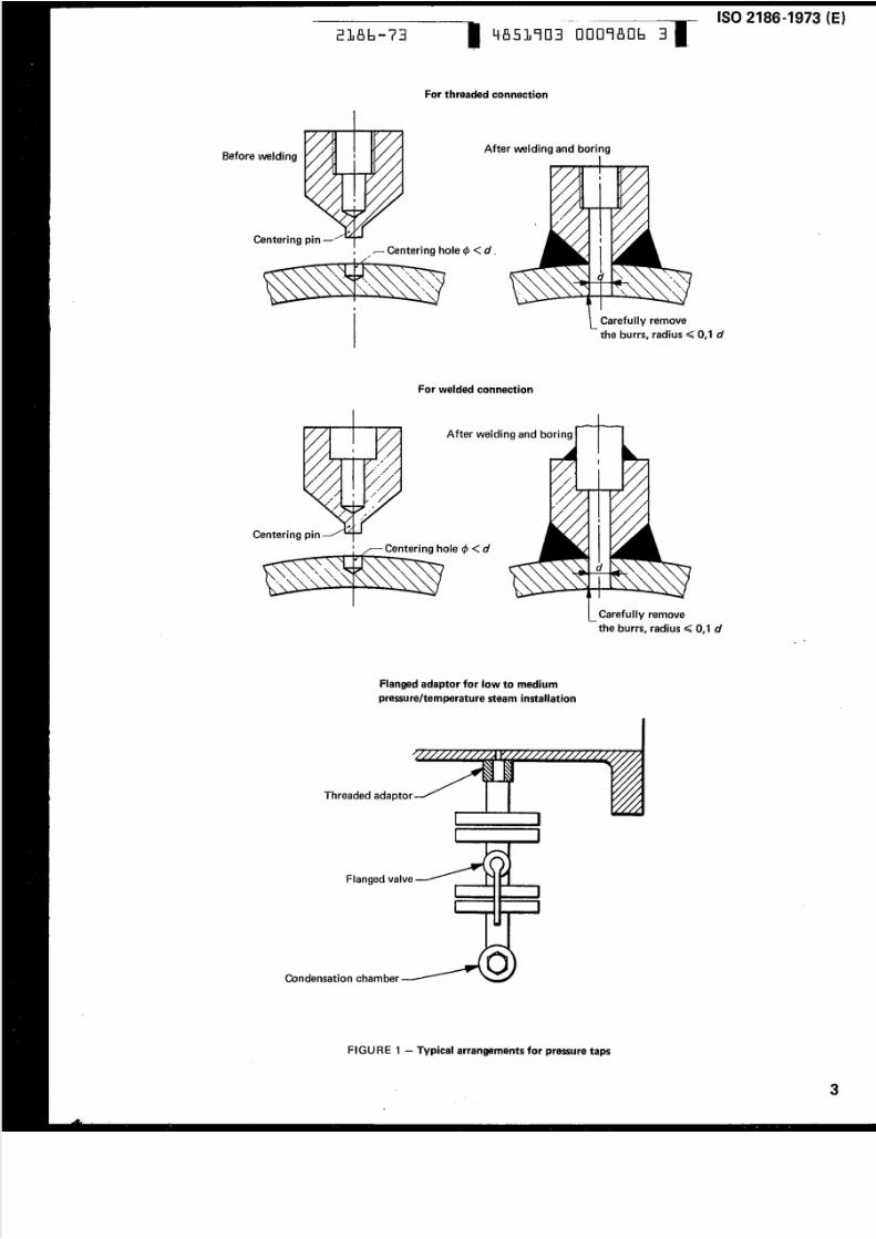
Som e typical arrangem ents fo r pressu re taps are g iven in
Figure 1, but it shou Id be noted that th e in form ation is
included fo r general gu i da n ee only.
5 ISOLATING VALVES
It is therefore necessary to consider variations in th e
capacitv o f condensation cham bers , bu t it is notr e commended that they shou ld be entirely omitted, even
when m i c ro -d is pl ac eme n t secondary devices are used ..1 Isolating valves are needed to separate the entire
m easurem ent system from the m ain pipeline when
necessary, bu t th ey shou ld not affect the p re ss ur e s ig na l.
It is r e commended that isolating va lves should be located
immedia te ly following th e primary e lemen t . If
co ndensatio n cham bers are installed the iso lating valves
may be fitted immedia te ly following th e c on de nsa tio n
chambers (see Figu re 18).
Practical considerations include:
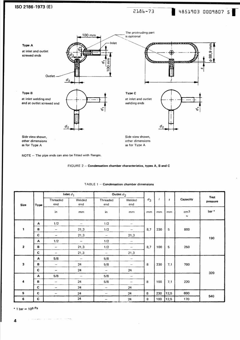
It is suggested that excep t when used with
micro-displacement dev ices, th e shape of th e condensation
chamber should be as shown in Figure 2. Fo r
m icro-d isp lacem en t devices, the condensation chambers
m ay take the fo rm o f sho rt leng th s o f unlagged p ipe
between the pressu re taps and the isolating valves.
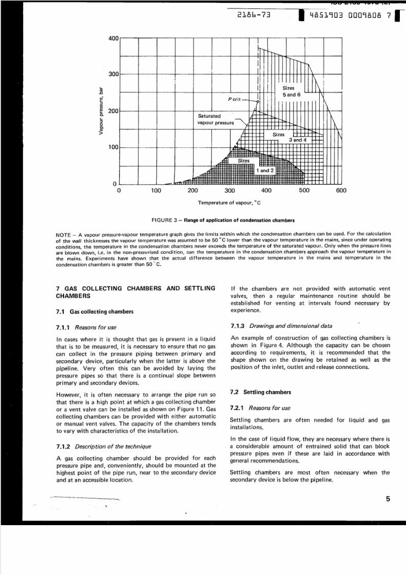
The capacities of th e condensation chambers shown in
Tab le 1 can be relate d both to secondary device max imum
displacement at maximum head as well as to steam
conditions, as shown in F igu re 3. Generally, it is a dv isa ble
to use condensation cham bers th at have a capacity two to
three tim es that o f th e secondary device displacement,
particu larly when it is known o r suspected th at large and
sudden variations in th e flo w rate m ay occur.
•he final choice both of th e valve specification and its
lo cation is left to th e instrument eng ineer and /o r u ser. T he
recommendat ions given here are therefo re sub ject to
alteration s w hich m ay b e n ec es sa ry in view of the operating
conditions and the nature of the fluid.
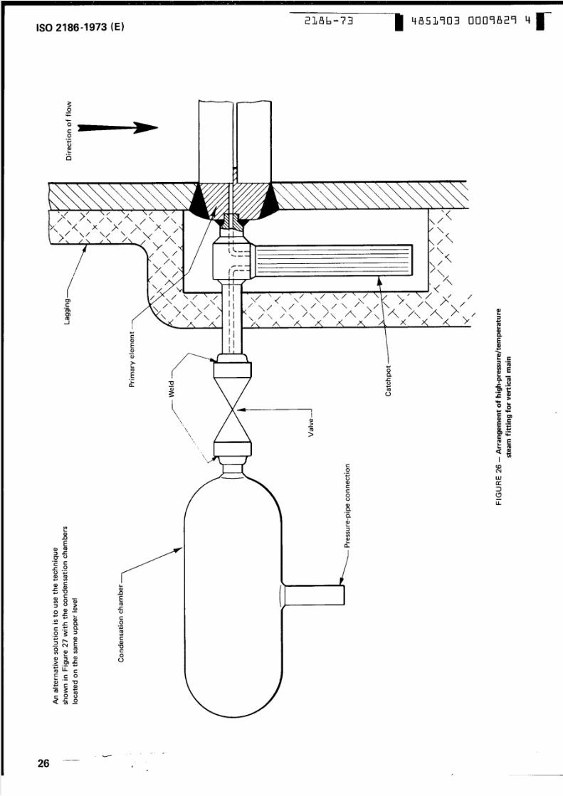
1) the insta lla tio ns o f valves suited to the pipe pressure ;In th e case of very h ig h p re ss u re /t em p e ra tu re steam, it is
advisable to use a catchpo t of approximately the s ame
vo l ume as the condensation cham ber, to protect the
primary e lemen t from damage caused by cool liquid from
the pressure piping re tu rn ing through the primary e lement
as a result of a large an d sudden change in flow rate. An
example of arrangem ent is given on Figu re 26.
The connecting p ipe between th e primary element an d
condensation cham ber/catchpot shou ld be e ither o f the
s ame materia l as t he p ip el in e, or o f e qu iv a le nt specification.
2) careful choice of both valve an d packing,
particularly in the case of corrosive o r d an ge ro us fluids,
and w ith su ch gases as oxygen ;
3) th e need to use valves whose design does no t affect
th e t ransmission of a p re ss ure sig na l, p artic ula rly when
th at s ignal is subject to an y degree o f fluctuation orpulsation.
5.2 Valve passages
It is r ecommended that th e genera ' rem arks about
constancy of diameter given in section 10 shou ld be u sed as
a gu ide in th is section as well. T hus, every a t tempt shou Id
be made to ensu re in th e case where the valva is
immed ia te ly adjacent to th e pressure tap that th e in te rn al
diameter of valve connections and the minimum passage
diameter inside the valve shou ld keep a constant value an d
preferably not be less than the internal diameter o f th e
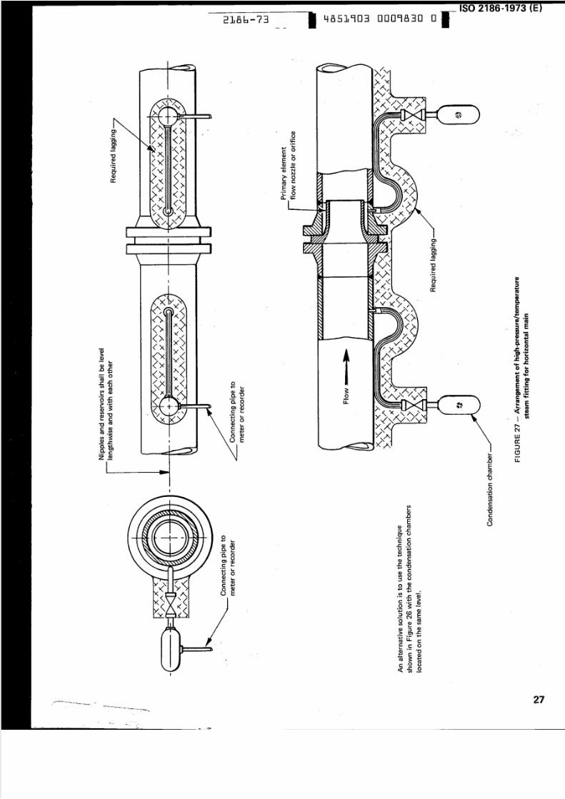
In th e case of primary elem ents and condensation chambers
in sta lled in vertical m ains, it is necessary to have bo th
condensation cham bers installed on the same level,
preferably that o f th e higher tap, and lagged as shown in..
F igure 20 for exam ple . T he bo re o f the connecting pipe
shou ld be large enough to avo id an y risk of blockage an d
secondary device response lag, and the pipe itself shou Id be
lagged.
2
5/10/2018 ISO 2186-1973 - slidepdf.com
http://slidepdf.com/reader/full/iso-2186-1973 5/36
2186-7~ 4851903 0009806 3
ISO 2186-1973 (E)---- -------~~
For threaded connection
Before weldingAfter u ve ld in g a nd boring
Centeri ng pin --f r- Centering hole < p < d ~
/
•
For welded connection
After welding and boring
Centeringpin-
d
Flanged adaptor for low to medium
pressure/temperature steam installation
Carefully remove
the burrs, radius ~ 0, 1 d
I
I
Carefully remove
the burrs, radius ~ 0, 1 d..
Threaded adaptor ->
Flanged valva=->
Condensation chamber ----------
FIGURE 1 - TYPiCalarrangements for pressure taps
•
3
5/10/2018 ISO 2186-1973 - slidepdf.com
http://slidepdf.com/reader/full/iso-2186-1973 6/36
ISO 2186 ..1973 (E)2186-73 4851903 0009807 5
The protruding part~-....--
is optional00 mm
,.-.InletEEC). .00C O
- e -
Type A
at inlet and outlet
screwed ends
t- E1: l E
oo
Outlet~
I
Type B Type C• •
at inlet welding end -+ - - - at inlet and outlet ~+- .. ...
and at outlet screwed end welding ends I
"fl- t-
~ ~
I
I•
Side view shown,
other dimensions
a s fo r Type A
Side view shown,
other dimansions
as for Type A
NOTE - The pipe ends can also be fitted with flanges.
FIGURE 2 - Condensation chamber characteristics, types A, Band C
TAS LE 1 - Condensation chamber dimensions
Inlet d1 Outlet d2Test
pressureapacityshreaded Welded Threaded Welded
T end en d end endy~~--------~----------~~--------~----------~--~--~~--~----------~--------~ize
bar *m3In mm mm mmm mm
A 1/ 2 1 /2
1 B 8001,3 8,7 230 5/2 -
c 21,3 21,3190
1/2 1/2
2 25021,3 8,7 100 5/2 i
c 21,3 21,3-
5/8 5/8
3 B 7004 5/8 230 7,1
c 24 24-320
5/8 5/8 -
4 5/8 2204 100 7, 1-
c 24 24
600230 12,584 24-540
24c 100 12,5 1704 : ' -.
...1 bar = 105 Pa
--- ------ - - -- - .....::::- - - - --
4
5/10/2018 ISO 2186-1973 - slidepdf.com
http://slidepdf.com/reader/full/iso-2186-1973 7/36
5/10/2018 ISO 2186-1973 - slidepdf.com
http://slidepdf.com/reader/full/iso-2186-1973 8/36
2186-73 4851903 0009809 9
/
is important that su fficient clearance shou ld be available
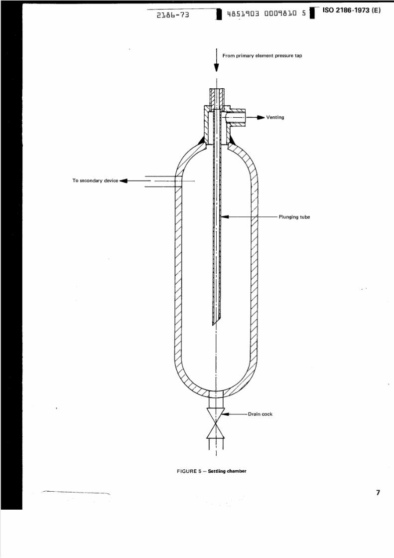
beneath the vesse l to a l low access to th e drain valve.In the case of gases, se ttling cham bers are advisable when
th e m e asu re d flu id is both dirty and/or wet.
Settling cham bers m ay be fou nd u sefu l for steam
installations where pressure pipe scaling c an d ev elo p. The v alve sh ou ld preferably be a fu ll bore type so that it
can be cleaned an d probed if blockage is suspected, or if the
cham ber is heavily en cru sted w ith d ep osits.
It should also be noted that pressu re holes, pressure pipe
bores, an d the connections to the settling chamber s should
be large r fo r very dirty liqu ids and gases.
The capacity of the settl ing chambers shou Id be as large as
practically possible or as large as the needs of the
installation demand. The proportions given in Figure 5 are
typical and should be sufficient for most purposes.
However , the frequency of maintenance and th e degree of
so lid and/o r condensation entrainm ent are matte rs that
shou Id decide the size of settl ing chamber to u se.
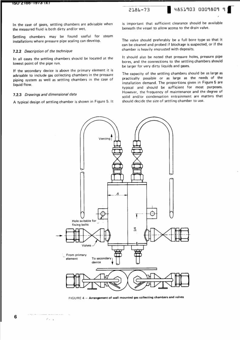
7.2.2 Description of the technique
In all cases the settling cham bers shou ld be located at th elowest point of the pipe run.
If th e secondary device is above the prim ary elem ent it is
advisable to include gas collecting cham bers in the pressure
piping system as well as settling chambers in the case of
Ilqu id ftow.
7.2.3 Drawings and dimensional data
A typical design of settling cham ber is shown in Figu re 5 . It
Hole su itable for _ _
fix in9 boIts
. ,Venting i
. . . . . . .-
A
tI L
Valves _/
" 1 : _N
FIGU RE 4 - Arrangement of wall mounted gas collecting chambers and valves
-- -- . - ----
6 ..., ._ ... ...
~. From primary-
element To secondary
device
5/10/2018 ISO 2186-1973 - slidepdf.com
http://slidepdf.com/reader/full/iso-2186-1973 9/36
To secondary device
1
2186-73 4851903 0009810 5-
..
From primary element pressure tap
Venting
Plunging tube
/ •
..-.....---Drain cock
{
l
FIGURE 5 - Settling Chamber
ISO 2186-1973 (E)
•
7
5/10/2018 ISO 2186-1973 - slidepdf.com
http://slidepdf.com/reader/full/iso-2186-1973 10/36
ISO2186-1973 (E)-------
4851903 0009811 7186-73
8 SPECIAL TECHNIQUES USED AS PROTECTION
AGAINST VERY COLD AMBIENT CONDITIONS
The interface between the m etered and the seal ing fluids
should be at exactly the s ame level in both sealing chambers
wh en th ere is no flow.In th e caseswhere pressure pipes con tain w ater i t i s p os sib le
to protect th em a ga in st frost by the use of heating elem ents
such as electrical tapes or steam coils.
The filling level is determined by m eans of purge valves and
w he re po ssible it i s des ir ab le to in sta ll v is ua l means which
allow co nstant co ntro l of t he in te rf ac e.
The exact use of these techniques depends on the particular
location, and advice cannot be generalized. It i s impor ta n t
to ensure that th e heating is controlled, uniform, an d of
equal amoun t to each pressure pipe and an y au xiliary u nit
included in the pipe run. W here po ssible the p re ssu re p ip es
should be run and lagged together, but care shou Id be taken
not to overheat l iquids in the pipes since this m ay cause
vaporization.
The sealing flu id fills the pressure pipes between the seal ingcham ber and the m eter.
For guidance, suitable sealing chamber dimensions for
industrial m eters are about 100 mm diam eter and 250 to
300 mm long.
It may be noted that the same techniques are useful when
warm or hot viscous flu ids are metered, to prevent
coagu lation or blockage in cold pressure pipes and an y
other n arrow p ass ag es.
W here m icro-displacem ent devices are used the sealing
cham ber can be elim inated or replaced by a pipe.
In all cases, the seal i ng cham ber capacity should be larger
than the m axim um volum e of m easuring liqu id displaced in
the m eter. W hen designing sealing chambers it should be
carefullv checked that their inside diam eters rem ain
constant over t he e ff ec ti ve w ork in g are a.9 SEALING CHAMBERS AND PURGE SYSTEMS
9.1 Sealing chambe rs
The m eter read ing shou ld be corrected to take account of
the displacement of the (s ea lin g flu id /m e te re d fluid)
interface in th e sealing chamber .
9.1.1 Sealing chambers without partition
Seal ing chambers containing a liqu id which separates th e
metered flu id from the fluid in th e m eter m ay be em ployed
where:
This correction will be of g re ate st im p orta nc e when th e
difference in density is greatest between th e se alin g and
m etered fluids. W hen m icro-displacem ent devices are used
this correction is negligible.
- the m etered flu id is corrosive;M ethod by which differen tial p ressure m ay be calculated
when seal ing cham bers are used with a U-tube type of
m eter is given in Annex A.the m etered fluid is Iikelv to congeal, freeze or
condense in the connecting pipes;
- the metered fluid i s v er y viscous;
- deposits are likely to occur in the connecting pipes
or in the meter, etc.
9.1.2 Sealing chambers with partitions
W hen the physical and chem ical characteristics of th e
metered fluid ar e such that a su itable sealing fluid cannot
be found, se alin g ch am b ers w ith p artitio ns m ay be used.It m ust, however, not be forgotten that the pipes
connecting pressure taps and seal ing chambers wilt no t be
protected by th e use of a seal ing flu id.
The sealing fluid should not mix or react with th e m e te re d
fluid or th e manomet r ic fluid an d shou ld differ in density
from both fluids by an am o unt sufficient to ensure a stable
interface.
Diaphragm an d bellows units are the simplest form of
partition generally used.
It is necessary to ensure that both sealing cham bers have
the s am e s tre ss /d is pla cem en t c ha ra cte ris tic .
Sealing chambers should be installed at the sam e level an d
as close as possible to th e pressure taps. When there is a risk
of congealing , freezing or condensation of the m etered
fluid, the connections from the pressure taps shou ld be
included in a pocket with the pipe lagging or be provided
with supplementary h ea tin g. T his m ight be provided as well
fo r s ea lin g c ham be rs , if they a re em plo ye d for Iiquefiabte
fluid flow measurements .
The volum etric displacem ent of th e sealing fluid over th e
full scale range of the m eter should be greater than th emax imum volume displaced by th e mete r itself.
G as v en tin g systems shou Id be used on both sides of the
partition.
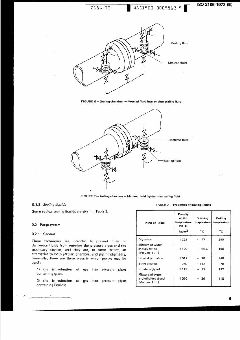
The general arrangem ents of sealing cham bers ar e shown in
F igu res 6 an d 7.
~n general the rem arks in 9 .1 .1 applv equally to sealing
chambers with partition.
In the cases where sealing chambers with partition are used
it is normal for the m anufacturer o f such units to provide
the relatio nship between input an d output signals.
- - . . . _ . . . _ - _ -
8
-•
5/10/2018 ISO 2186-1973 - slidepdf.com
http://slidepdf.com/reader/full/iso-2186-1973 11/36
•
•
-~~------ ISO 2186-1973 (E)2186-73 4851903 0009812 9
~- Metered fluid
F IGURE 6 - Sealing cham bers - Metered fluid heavier th an sea ling flu id
;' Sealing fluid
..
FIGURE 7 - Seal ing chambers - Metered f luid lighter than sealing fluid
9.1.3 Sealing liquids
Some typical sealing l iquids are given in Table 2.
TABLE 2 - Properties of sealing liquids
Density
at the Freezing Boiling-
temperature temperature temperatureKind of liquid
20°C
kg/m3 °c °c
-
Glycer ine 1 262 -- 17 290.
Mixture of water
and glycer i ne 1 130 -22,5 106
(Volume 1 : 1)
Dibutvl phthalate 1 047~
35 340. . . . . _ _ .
Ethy l alcohol 789 -112 78
Ethylene glycol 1 113 -12 197
Mi xture of water
an d ethylene glycol 1 070 - 36 110
(Volume 1 : 1)
9.2 Purge system
9.2.1 General
These techniques are intended to prevent dirty or
d an ge ro us flu id s from entering the pressure pipes an d the
secondary devices, and they are, to some extent, an
alternative to both settling chambers and sealing chambers.
Generally, there ar e three ways in which purges m ay be
used:
1) the introdu ctio n of gas in to pressure
containing gases;
2) the introduction
containing liquids:
of gas into pressu re•
Pipes
~- .. - . ... 22 2 2 2C
.r
9
. J W z= w e .. _ .. . . .
~ -
5/10/2018 ISO 2186-1973 - slidepdf.com
http://slidepdf.com/reader/full/iso-2186-1973 12/36
ISO 2186 ..1973 (E)4851903 0009813 0186-73
3) the introduction of Iiqu id into pressu re
containing liquids;
..
pipes 9.2.3 Introduction of gas into pressure pipes containing
liquids
The rate of purge will depend on :
- whethe r the m easured flow is steady;
- the type of secondary device used;
- the total capacity of the pressure pip e ru ns.
It should be em phasized that in practice care should be
taken to ensure that the purge does not influence th e
performance of th e secondary dev ice nor the fluid
temperature equilibrium between th e tw o pressu re pipes .
In div idu al d eta ils are given in th e f ollowi ng clauses.
The same general commen ts apply as given in 9.2.2, bu t
there are im portan t facts to note.
Gas purge into liquid filled pressure pipes can cause
difficulty an d error if the metered flow is unsteady, if small
differential p ressures are used , an d if gas vessels ar eincluded in the pressure pipe system.
Furtherm ore, the considerable difference between the
ki nematic v iscosi t ies of the gas and the Ilqu id , as well as
surface tension effects, make abrupt variations in flow rate
or pressure m ore difficult to counter and there is a real
chance that, temporar i ly, the metered fluid will enter the
pressure pipes and cause spurious differential pressure
signals.
9.2..2 Introduction of gas into pressure pipes containing
gas
This technique is advantageous in cases where there is a low
pipel ine pressu re , and the seco nd ary dev ice is lo cated abo ve
the pipeline.
It is also important to note that with this system the
secondary device is operating with gas although it is
concerned with Iiq u id flow, an d therefore, that the
secondary device has a dry calibration relationship between
differential head and flow. It also is important that
Iiquid/gas discontinuities in the pipe system shou Id occur at
the same levels.
If th e flow rate varies with tim e to a considerable extent I
and the m agnitude of variation is large, then it is best to use
a purge flow rate equ iva lent to the m eter to tal capacity
between zero and m axim um displacem ent in o ne m inu te,
Steady flows do not need such a high purge flow, but very
small purge rates should be avoided because they are
difficu It to control ~
Equally , th e use of larger purge flows w ill m ean that special
care will have to be taken to avoid an out-af-balance of
pressure in the pressure piping. It would, for example, mean
that pressure taps and pressure bores shou ld be large
enough to avo id pressu re losses created by a large pu rge
flow. For the s ame reasons it is always necessary to avoid
changes of cross-sectional area at any point in th e p re ss ur e
p ipe system when purge techniques ar e used. Furthermore,
both the high and low pressure m e te r c on ne ctio ns should
be of the sam e length and have the s ame num ber of fittings.
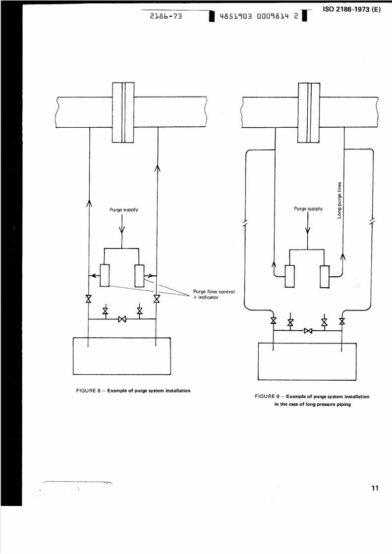
In the case of long pressure piping, it may b e n ec es sa ry to
place a pipe in which the purge fluid would flow up to th e
pressure tap and a second pipe, transm itting th e pressure, to
the secondary device, w ith ou t pressu re drop effect.
In order to keep the purge flow rates equal in both pressure
pipes it is recommended that small variable-area m eters or
sight glasses be included in the purge system. They shou Id
be located at a point between the purge co ntrol valve and
th e point at which th e purge flow enters the pressure pipes,
It is of course necessary to use g as p urg e pressu res that ar e
well above the pi pel ine pressure. Control of purge rate is
usually obtained by means of some type of needle valve or
a simple purge flow regulator.
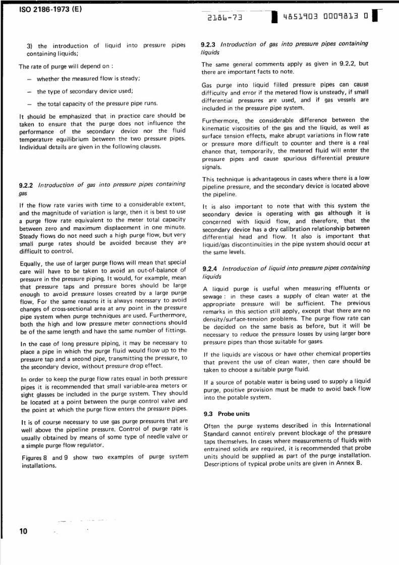
Figures 8 and 9 show two examples of purge system
installations.
9..2.4 Introduction of liquid into pressure pipes containing
liquids
A liquid purge is usefu l when m easuring effluents or
sewage: in these cases a supply of clean water at the
appropriate pressure will be sufficient. The previous
remarks in this sectio n still apply I except that there are no
density Isurface-tension problems. The purge flow rate can
be decided on the sam e basis as before, but it will be
necessary to reduce th e p ressu re lo sses by using larger bore
pressu re pip es than those su itable fo r gases.
If the l iquids are viscous or have other chem ical properties
that prevent the use of clean water, then care shou Id be
taken to choose a su itable purge fl u id .
If a so urce of potable water is being used to supply a liquid
p urg e, p ositiv e provision must be m ade to avoid back flow
into the potable sys tem.
9.3 Probe units
Often the purge system s described in this International
S tan dard can no t entire ly prevent blockage of th e pressure
taps themselves. In cases w here measurements of flu ids with
entra ined sol ids are requ ired, it is recommended that probe
units should be supplied as part of the purge installation.
Descriptions of typical probe units are g iven in Annex B.
- - - ---- -_ _ --
10...
. . . .
5/10/2018 ISO 2186-1973 - slidepdf.com
http://slidepdf.com/reader/full/iso-2186-1973 13/36
ISO 2186-1973 (E)2186-73 4851903 0009814 2
Purge supply
-
)J ~
JIIl
\t
1 ~
J,
FIGURE 8 - Example of purge system installation
• E E E EI I W II ' : := = Cooz .
~ '--- -- - -
..--
u:tQJ
C..--
Purge supply
Q)IJ)
'-: : : J
a.C)
co_J
Purge flow control+ indicator
•
FIGURE 9 - Example of purge system installation
in the case of long pressure piping
11
5/10/2018 ISO 2186-1973 - slidepdf.com
http://slidepdf.com/reader/full/iso-2186-1973 14/36
ISO2186-1973 (E)
2186-73 4851903 0009815 4
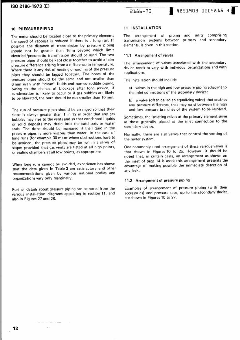
10 PRESSURE PIPING 11 INSTALLATION
The mete r should be located close to the prim ary elem ent;
the speed of reponse is reduced if there is a long run. If
possible the distance of transmission by pressure pipi ng
should no t be greater than 16 m beyond which l imit
electrical/pneumatic transm ission shou ld be used. The two
pressure pipes should be kept close together to avoid a falsepressu re difference arising from a difference in temperature.
Where there is any risk of heating or cooling of th e pressure
pipes they should be lagged together . The bores of th e
pressure pipes shou ld be the same an d not sm aller than
6 mm even with "clean" fluids an d non-corrodible piping,
owing to the chance of blockage after long service. If
condensation is Iikelv to occur or if gas bubbles are likely
to be liberated, th e bore shou Id be not smaller than 10 mm .
The arrangement of piping and units compris ing
transmission systems between primary an d secondary
elements , is given in this section.
11.1 Arrangement of valves
The arrangement of valves associated with the secondary
device tends to vary with individual o rg aniz atio ns an d with
appl icatio ns.
The installation should include
a) valves in the high an d low pressure p ip in g a dja ce nt to
the inlet connections of the secondary device;
The ru n of pressure pipes shou ld be arranged so that their
s lope is alw ay s greater than 1 in 12 in order that an y gas
bubbles may rise to the vents an d so that condensed liquidsor solid deposits m ay drain into th e catchpots or water
seals. The slope should b e in crea sed if th e liquid in the
pressure pipes is more viscous than water. In the case of
long runs (for example 30 rn) or where obstructions have to
be avo id ed, th e pressure pipes m ay be run in a series of
slopes provided that gas vents are fitted at all h ig h po in ts,
o r sea lin g c ham b ers at all low points, as appropriate.
b) a valve (often called an equalizing valve) that enables
an y pressure difference that may exist between the high
an d low p ressu re bra nc hes of the system to b e r es ol ve d.
Somet imes , th e isolating valves at th e prim ary elem ent serve
as those genera Ily placed at the inlet c on n ec ti on to th e
secondary device.
Normally, there are also valves th at control the venting of
the meter system.
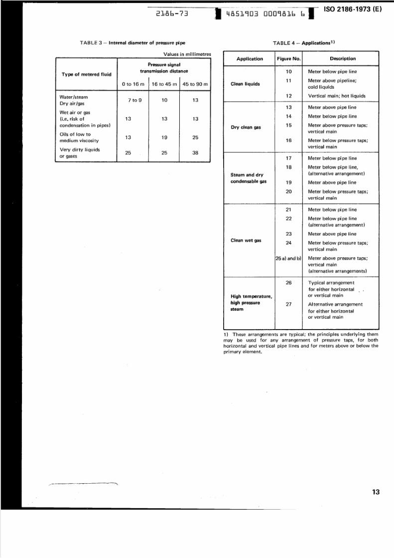
When long runs cannot be avoided, experience has shown
that the data given in Table 3 are satisfactory and other
recommendations given by various national bodies and
organizations vary only marginally .
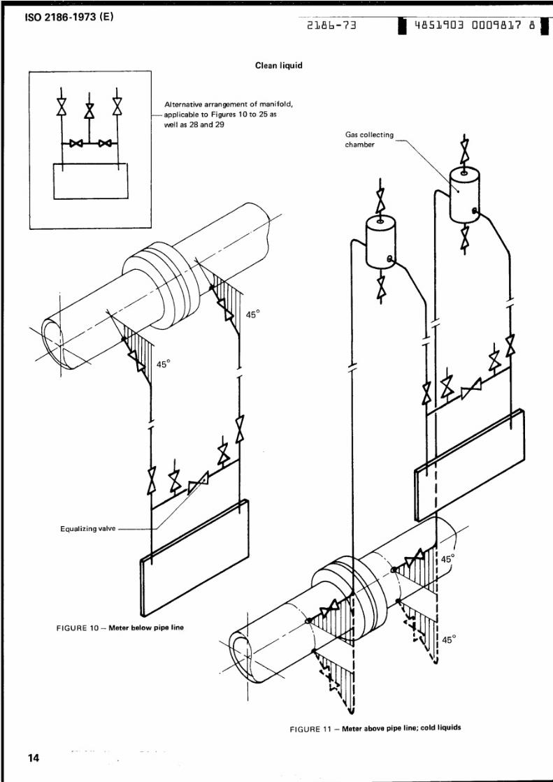
One commonly used arrangement of these vario us valves is
that shown in Figures 10 to 25. However, it should be
noted that, in certain cases, an arrangem ent as shown on
the inset of page 14 is used; this arrangement presents the
advantage of making possible the im m ediate detectio n of
any leak.
Further details about pressure piping can be noted from the
various installation d ia gra m s a pp earin g in section 11, and
also in Figures 27 an d 28.
11.2 Arrangement of pressure piping
Exam ples of arrangement of pressure piping (with their
accessories) and pressure taps, up to the secondary device,
are shown in Figures 10 to 27.
12 - -
5/10/2018 ISO 2186-1973 - slidepdf.com
http://slidepdf.com/reader/full/iso-2186-1973 15/36
--------___._.,----- -------- -- - - ---------
2186-73
TAB LE 3 - Internal diameter of pressure pipe
Values in millimetres
Type of metered fluid
25
Pressure signal
transmission distance
o to 16m 16 to 45 m 45 to 90 m
Water IsteamDry air/gas
Wet ai r or gas
(l.e, risk of
condensation in pipes)
Oils of low to
med ium viscosity
10to 9 13
13 13 13
13 19 25
Very dirty liquids
or gases385
........-~ a--- -- - --- ••p c - - -
4851903 0009816 6ISO 2186-1973 (E)
TABLE 4 - Applications1)
Figure No.
10
11
12
13
14
15
16
17
18
19
24
27
20 Meter below pressure taps;
vertical main
21 Meter below pipe line
22 Mete r below pipe line
- (a lternative arrangement)
23 Meter above pipe line
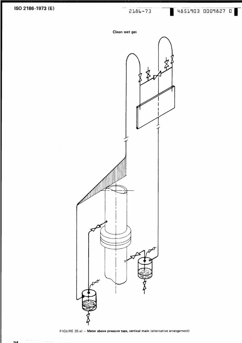
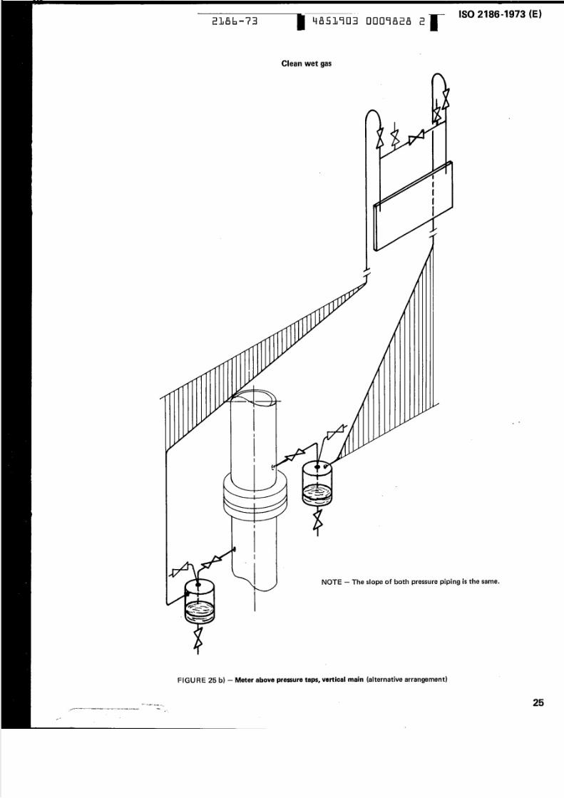
25 a) and b) Meter above pressure taps;
vertical main
(a l ternative arrangements)
26 Typical ar r angemen t
for either horizontal
or ve rti cal main
Descriptionpplication
Clean liquids
Dry clean gas
Steam and dry
condensable gas
Clean wet gas
High temperature,
high pressure
steam
Meter below pi pe line
Meter above pipeline;
cold liquids
Vertical main; hot liquids
Meter above pipe line
Meter below pipe line
Meter above pressure taps;
vertical main
Meter below pressure taps;
vertical mai n
Meter below pipe tine
Meter below pi pe line,
(alternative arrangement)
Meter above pipe line
Meter below pressure taps;
vertical main
..•
Alternative ar r angemen t
for either horizontal
or vertical main
1) These arrangements are typical; the pri nci pies underlying them
m ay be used for any arrangement of pressure taps, for both
horizontal and vertical pipe lines and for meters above or below the
prim ary e le m en t.
13
. . . .
5/10/2018 ISO 2186-1973 - slidepdf.com
http://slidepdf.com/reader/full/iso-2186-1973 16/36
ISO 2186-1973 (E) ---_.--~~~----
2186-73 4851903 0009817 8
Clean liquid
Alternative a rrangement of mani fo ld ,
..,....__ppl icable to Figures 10 to 25 as
\f\'811as 28 and 29
Gas collecting .-...
chambe r
I
FIGURE 10- Meter below pipe line
II
II
FIGURE 11 - Meter above Pipe line; COld liquids
~ -- . . . . -- - - -
14 oil
5/10/2018 ISO 2186-1973 - slidepdf.com
http://slidepdf.com/reader/full/iso-2186-1973 17/36
~ _ _ & a & _ . 7__:a _ _ S _
•
2186-73 4851903 0009818 0
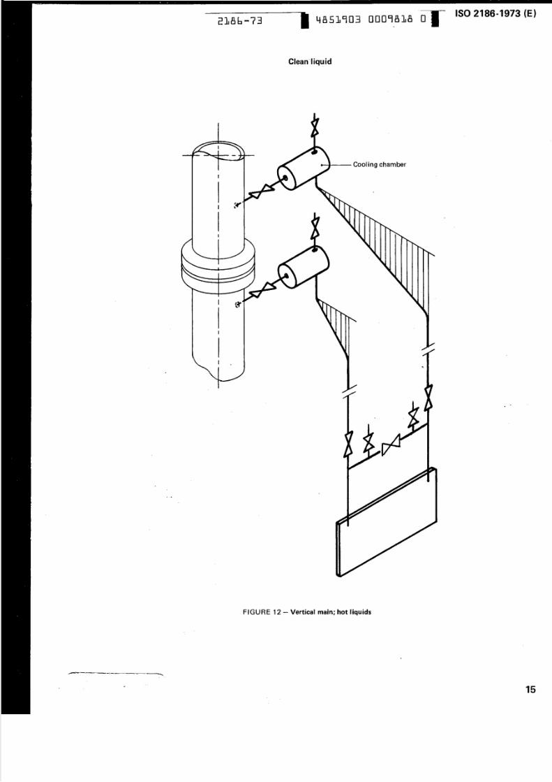
Cleanliquid
.................-- Cooling chamber
I
I :""
r
. . . .
FIGURE 12 - Vertical main; hot liquids
ISO 2186-1973 (E)
•
15
5/10/2018 ISO 2186-1973 - slidepdf.com
http://slidepdf.com/reader/full/iso-2186-1973 18/36
ISO2186-1973 (E)
16
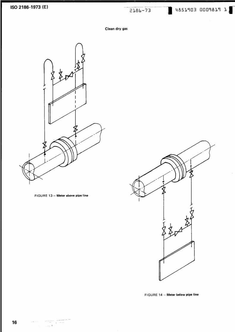
Clean dry gas
FIGURE 13 - M eter above pipe line
... -- - -- - -
--'".
2186-73 4851903 0009819 1
I
F IGURE 14 - Meter below pipe line
5/10/2018 ISO 2186-1973 - slidepdf.com
http://slidepdf.com/reader/full/iso-2186-1973 19/36
ISO 2186 ..1973 (E)2186-73
I
II
I
I
I
I
I
•
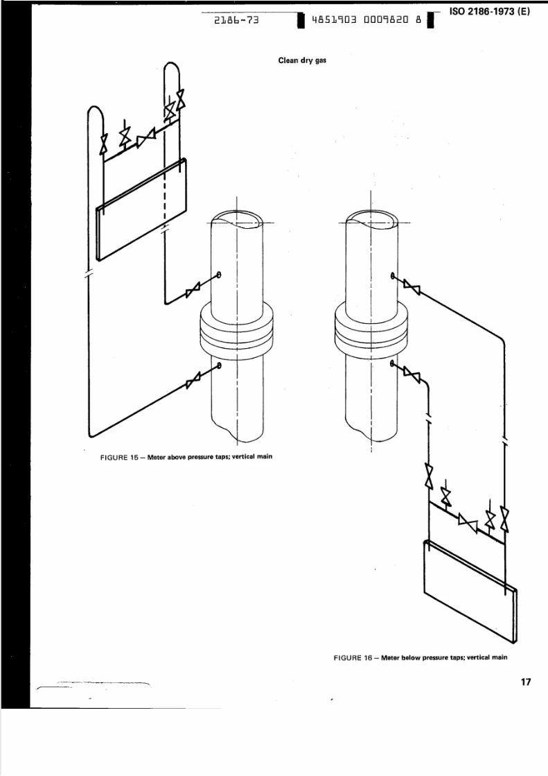
FIGU RE 15 - Meter above pressure taps; vertical main
........ z - - ... . _ .. ::;zz;z pis •
~ ~ - _ _ . - . . . . . . . . t . - - =
4851903 0009820 8
Clean dry gas
I
I
.....
!
I
..
FIGU RE 16 - Meter belOW pressure taps; vertical main
17

5/10/2018 ISO 2186-1973 - slidepdf.com
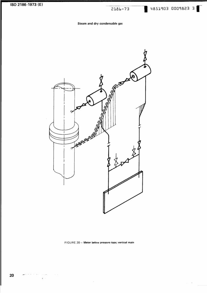
http://slidepdf.com/reader/full/iso-2186-1973 20/36
ISO 2186·1973 (E)2186-7:3
4851903 0009821 0-
Steam and dry condensable gas
.........-- Condensation chamber
..
FIGU RE 17 - Meter below pipe line
FIG URE 18 - Meter below P i PB line (aIternative arrangement'
-- --- - - --- - ----- -- - --- -- -- - --
18. . . . -• ...
-.. ~ .; ~
. . . . .
5/10/2018 ISO 2186-1973 - slidepdf.com
http://slidepdf.com/reader/full/iso-2186-1973 21/36
ISO 2186-1973 (E)
2186-73 4851903 0009822 1
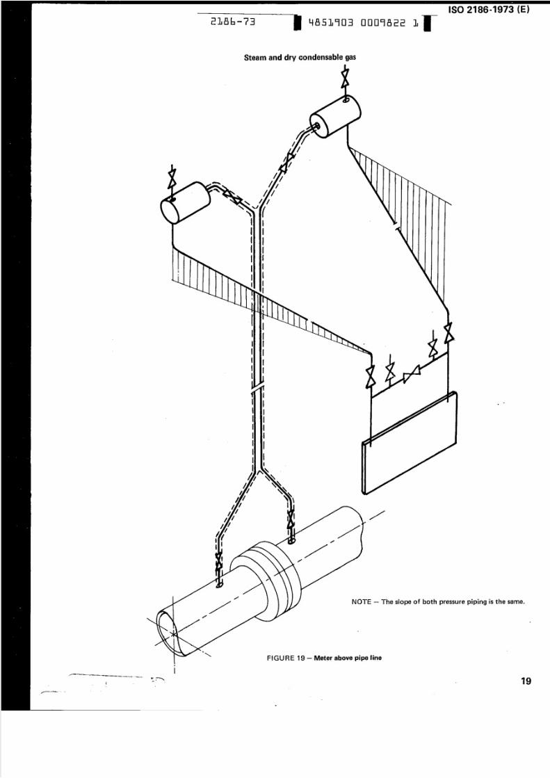
Steam and dry condensable gas
-[ I
I II II II II II
•
NOTE - The slope of both pressure piping is the same.
•
•
FIGURE 19 - Meter abovePipe line•
I
...- 19
./ - -- -
5/10/2018 ISO 2186-1973 - slidepdf.com
http://slidepdf.com/reader/full/iso-2186-1973 22/36
ISO 2186 ..1973 (E) ------~----~--
2186-73 4851903 0009823 3
Steam and dry condensable gas
I
,
I
I
FIG URE 20 - Meter below pressure taps; vertical main
20- - - -
-~
5/10/2018 ISO 2186-1973 - slidepdf.com
http://slidepdf.com/reader/full/iso-2186-1973 23/36
•
2186-73 4851903 0009824 5
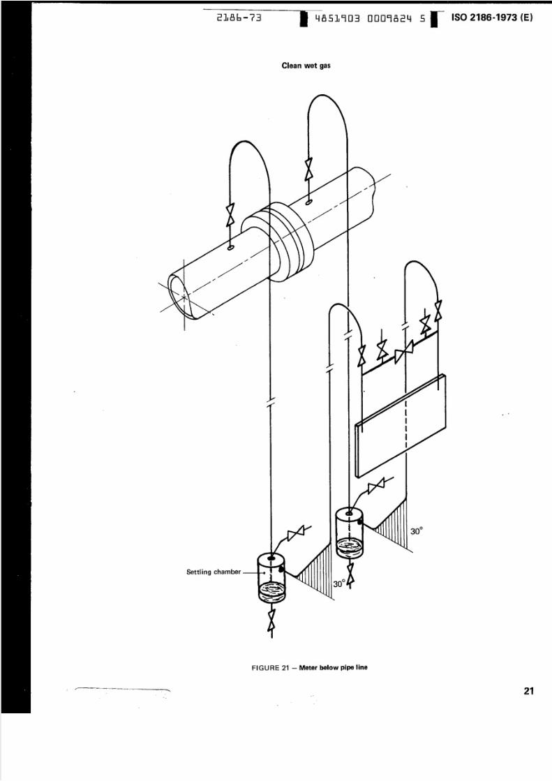
Clean wet gas
I
III
II
Settling chamber-
FIGURE 21- Meter below Pipe line
__=-=-=-Z:::~~~F _ e_ -=------=---- .. __ ,_
ISO 2186-1973 (E)
•
21
5/10/2018 ISO 2186-1973 - slidepdf.com
http://slidepdf.com/reader/full/iso-2186-1973 24/36
--- - -
ISO2186-1973 (E) 2186-73 4851903 0009825 7
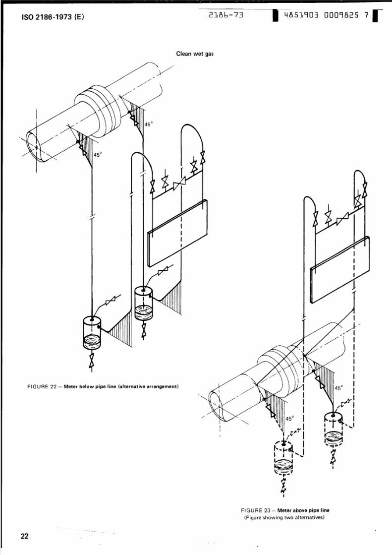
C lean wet gas
. . . .
FIGURE 22 - Meter below pipe line (alternative arrangement)
FIGURE 23 - Meter above pipe line
(Figure showinq two alternatives)
-. . . .
22
5/10/2018 ISO 2186-1973 - slidepdf.com
http://slidepdf.com/reader/full/iso-2186-1973 25/36
2186-73 4851903 0009826 9ISO 2186-1973 (E)
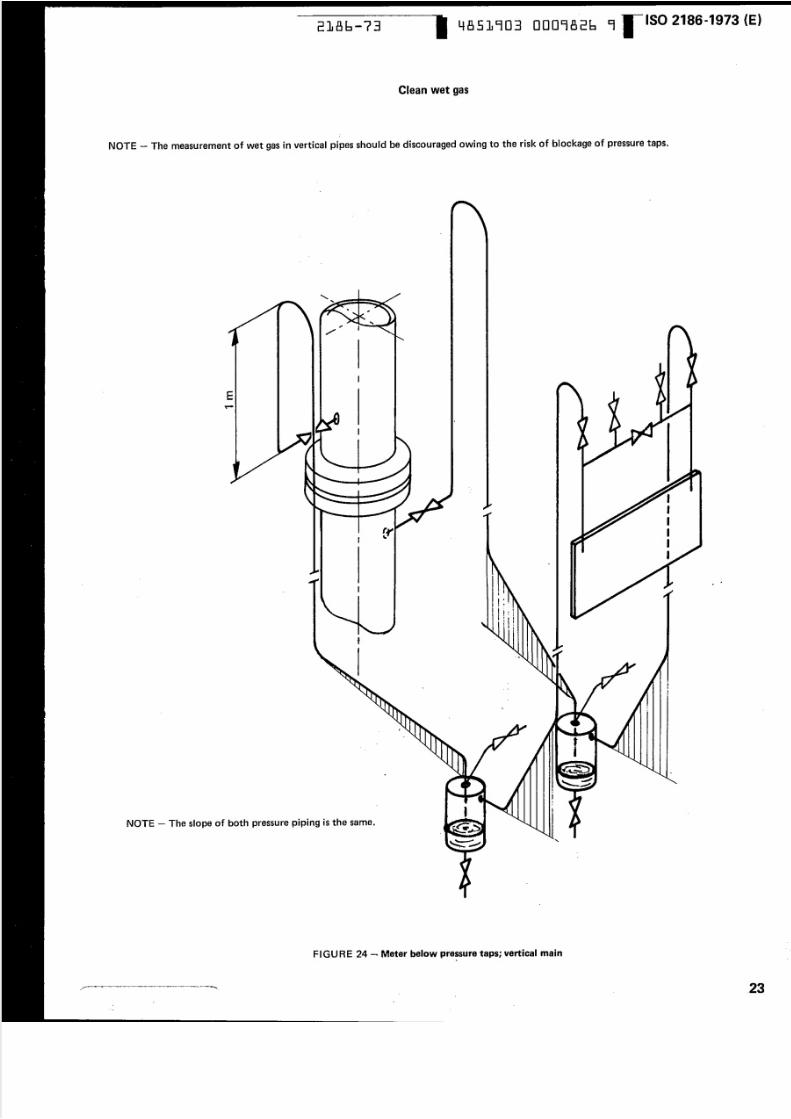
Clean wet ga s
NOTE - The measurement of wet gas in vertical pipes should be discouraged owing to the risk of blockage of pressure taps.
NOTE - The slope of both pressure piping is the same.
I
E
•
I
r
IIIIJI
I •
I ,t
II
I '!-~
..- -
I t- •- . •I • I
I I I
!I riI·t•
f
...tL
tt
•..
FIGU RE 24 -.: Meter below pressure taps; vertical main..
.~ -
-- .._ c . _
_ 2 3
5/10/2018 ISO 2186-1973 - slidepdf.com
http://slidepdf.com/reader/full/iso-2186-1973 26/36
ISO2186-1973 (E)2186-73
- - ---- -- -----------~-
4851903 0009827 0
Clean wet gas
I
I
I
I
FIG URE 25 a) - Meter above pressu re taps, vertical main (al ternative arrangement)
5/10/2018 ISO 2186-1973 - slidepdf.com
http://slidepdf.com/reader/full/iso-2186-1973 27/36
2186-73 4851903 0009828 2ISO 2186-1973 (E)------
Clean wet gas
•
I
•
I
NOTE - The slope of both pressure piping is the same.
FIGU RE 25 b) - Meter above pressure taps, vertical main <a lt ernat iv e a rr a ngemen t)
25~ ._ - - __ ._ = _ = .. . __ ..
_. .
5/10/2018 ISO 2186-1973 - slidepdf.com
http://slidepdf.com/reader/full/iso-2186-1973 28/36
ISO 2186-1973 (E)2186-73 4851903 0009829 4
-. . . .'+-
oCo
3 :o
.-
11
c
" - ; ( > / / /
//~- /"./, "Y, ~ x ;;.:. X )<
» : < : ><> ,,/ 'y < :
/ / r-;'y/ ,,/-, »< ,.--
I Y " / ( r -
I IC1
f :..-CIC1 I Im_J
j II
+- - 1 Ic :Q
I IEQ) I-Q)
>1....
m
E. _~ -c, -1J
~
c:o
...
1
QJ:>-\\
co
>\
.-. . . . .uOJ
ecCuO Ja.'lo-
a.1
O J~
~
enVJC 1>'-a..
'-Q)
.cEm..co
Co,.,-
-
26
5/10/2018 ISO 2186-1973 - slidepdf.com
http://slidepdf.com/reader/full/iso-2186-1973 29/36
2186-73-- --
4851903 0009830 0
.-D)
Cl-c o-
. . . . . .:J-
crQ)0:
C D
. .: : : : I. . . .CQa..IDa.E11.t: cm .-. . c a
.. ::I EII -. u ca.. . . . . .e, c• 0.s: NC II .-. - . ..c 0' t - . c :o )..., ac ....m Q3
E ,5ell =",-C+-
~ E~ . mI t;
r- -N
wc c:>o
e n
@
c: :
..
. . . . . .CJ
•Q. 1
C)
C J
m
. . . . . .'+-
..
-.-
-c ,~+-''-0
Ql
c:
s . . . (XOJ 3 a . .
. . . . . . .E 0
:::J /\(er
Q OJ
Q)
.--
a:
Q NN
> 0'- ecoE ~. . . . . . 0-e, -
".().
(xx/
(~ X)~ (xQ) y'> < 'x) y <- L..
Ql Q) ()<. c . c. . . ,
< X»:
= 0C O . c x <-5 u < ; < 0
en m >(L. Q) X
. . . I..-
I a
Q) QJ
o.cc.-C
t: .~,- .. .
Cl)-~
0.0
~-c
c nU
..r : : ~
'- c..-
1J tV
. . . . . . . . .u
0-c: Q)
Q)
tV .~
Cs . . .QJ
r. n 5 :c . . . . . .
~.I:
0 Q)
8 : 1 5 ,• 0E
1_ CZ Q)-
so~
L L-
I
0+-' . . .Q) Q)
c.-C11_ s . . .Q. 0
0°
c: f. . . . .. . . , '-00(U
L.
~
!C : Q)
-: e . . . . ,0 Q)
<(J E
<y
--
I
-~- - ..
enL-a >.cE
Q) m::J ..cc- c.- c. E 0(J .~
O J co..... en
a J C
..c OJ~~
GJ c:U) 0::J U
o Q). . . , - ' =UJ +a' _:
. - . . c : Q)
C......,111 Q)
.2 3 : -+- (0 Q)
~NEo III\ coC I) " " en
I..-m ~ Ql
> Cl s:.,p .- +J
co LL eE c 0(1) .._
.., c: -0- ::. Q)ct J > ......,
coc: .0 u« .t: 0
- e n -
I-
!Ec o.coc ::o. ,_..+-'(0enCOJ-cco(J
LL
27"

5/10/2018 ISO 2186-1973 - slidepdf.com
http://slidepdf.com/reader/full/iso-2186-1973 30/36
ISO2186-1973 (E)---- --~~~ -- - - - - ---------.-.
4851903 0009831 2186-73
ANNEX A
FORMULAE FOR DIFFERENTIAL PRESSURE CALCULATION WHEN SEALING CHAMBERS ARE USED
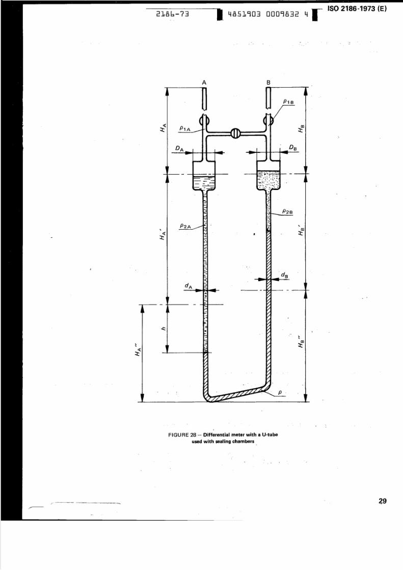
NOTE - Figures 28 and 29 and corresponding calculation formulae (sections A.1 and A.2) relate to the case when the metered fluid is l ighter
than the sealing fluid.
A.1 MEASUREMENT BY MEANS OF A DIFFERENTIAL METER WITH A U-TUBE (Figure 28)
p -p =A B
p g
-
d 2A
---d 2B
HI
+ hA
I fP1A=P1S=P,
an d if P2A =P2B = = P 2
i.e. if th e m etered fluid ma ss d en sit y is the sam e in both higher and lower pressure branches
i.e. if the sealing fluid m ass density is the sam e in both sealing chambers,
then the formula giving the differential pressure m ay be simplified as follows:
•
I d 2\ B
dA2 d
A2
-- + ~DS2 DA 2
H '1 - H II+ hB A
H -H -hB A
d 2A
dA2 d
A2
+ ...·~----1dA2
H '-H '+h----B AL
-+1D 2A
d 2B
D 2B
If i.e. if both p re ssu re ta ps are at the same level,
i.e. if the reference planes (0 mark) ar e similar in both higher and lower p re ss ure b ra nc he s
respectively for sealing chambers on th e one hand an d meter on the other hand,
if H I = H I
A B
H"=H"A B
n d
then the formula giving th e differential pressure m ay be f urth er s im p lif ie d as follows:
28
d 2A
dA2 dA2
----+--Ds2 DA2
1+-d 2B
5/10/2018 ISO 2186-1973 - slidepdf.com
http://slidepdf.com/reader/full/iso-2186-1973 31/36
--
I
-zw ... ..... .- ... . . . . . .
«P1A= t
m:t:
. . . .
-.
DA 08
2186-73 4851903 0009832 4
.. . . . . ;
' •
A B. . . . . . .-----. . . . . . . . . . :
--- - - - - - - --------
. .
-
..
'-
" aJ: : r :
.....
.r. p
..
FIG U R E 28 - D iffe rential meter with a U~tube
used with sealing chambers•
I ...
....
... ..
ISO-2186 ..1973 (E)
-... :
•
•
-
•..
29.
5/10/2018 ISO 2186-1973 - slidepdf.com
http://slidepdf.com/reader/full/iso-2186-1973 32/36
ISO2186-1973 (E) -----~--- - -
2186-73 4851903 0009833 6
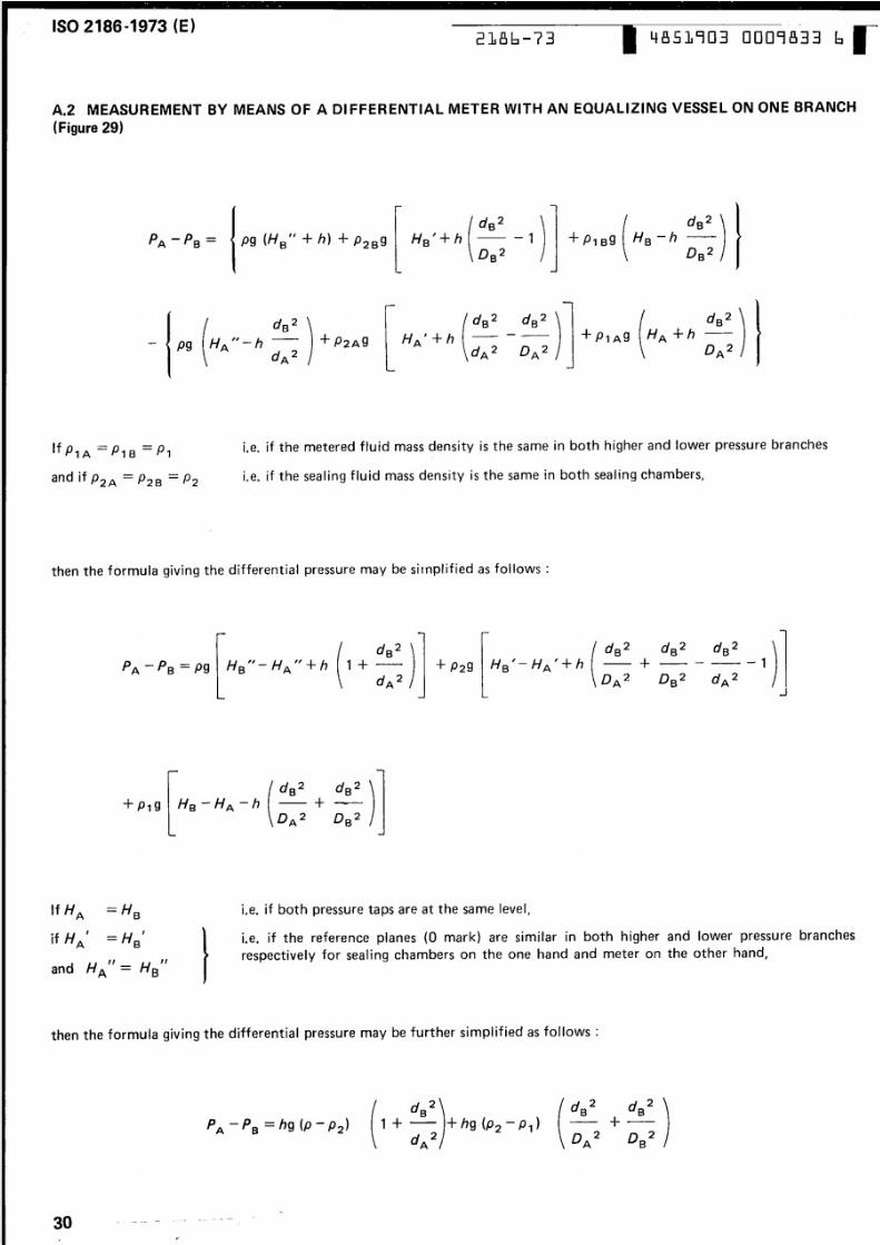
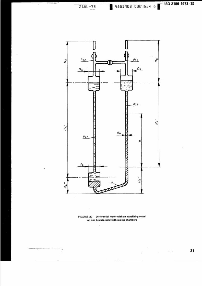
A.2 MEASUREMENT BY MEANS OF A 01FFERENTIAL METER WITH AN EQUALIZING VESSEL ON ONE BRANCH
(Figure 29)
- p g
- -_ _-
J
l.e, if th e m etered flu id m ass density is th e s ame in both h igher and lower pressu re branch esI fP1A==P1S=P,
and if P2A = = P2B =P2 i.e. if the sealing fluid mass density is the sam e in both sealing chambers ,
i.e. if b oth pressure taps ar e at the same level,
l.e, if th e reference planes (0 m ark) are similar in bo th higher and lower pressure branches
respectively fo r sealing cham bers on the one hand and meter on the other hand,
then the formula giving th e differential pressure m ay be si rnpl ified as follows:
dB
2
1 + a ~ ...
dA2
--+~b&-
=HB
=H'B
" "nd HA = HB
+ - -1
.. J
then the formula giving the d iffe re ntia l p re ss ure m ay be further simplified a s f o ll ow s :
30 ---- -
•-...
d 2B
2B
5/10/2018 ISO 2186-1973 - slidepdf.com
http://slidepdf.com/reader/full/iso-2186-1973 33/36
..
«:r:
..
2186-73 4851903 0009834 8--
P1A c o
: r :1B
•
---------- - - - - - - --
4
P2B
P2A
-_....-. . . . . . . . .~--_.. _ - -.-... --... .-.-
p
FIGURE 29 - Differential meter with an equalizing vessel
on one branch, used with sealing chambers
r -- .. . - " - - :: w : : : - - . -- -: -1 1: 1. _ .- - _ _ __ .. . .. .. ..
-~
ISO 2186-1973 (E)
.
•
..
31:10.
5/10/2018 ISO 2186-1973 - slidepdf.com
http://slidepdf.com/reader/full/iso-2186-1973 34/36
ISO 2186-1973 (E)
2186-73 4851903 0009835 0
ANNEX B
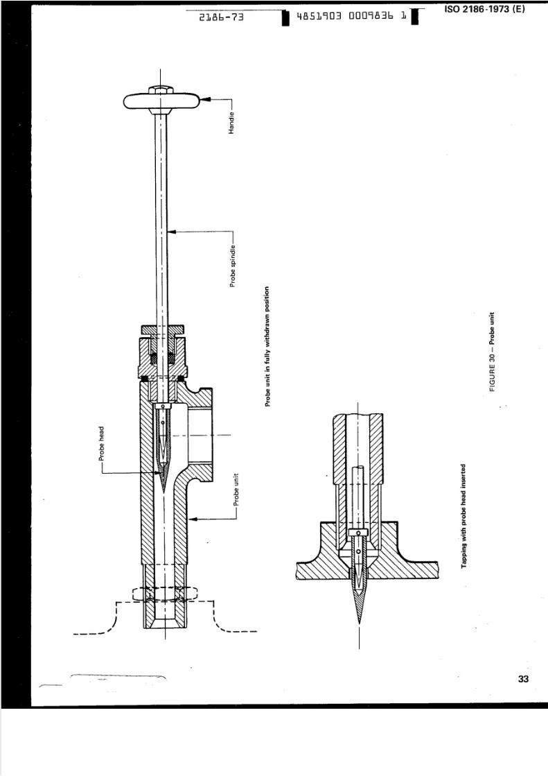
DESCRIPTION OF TYPICAL PROBE UNITS
General design requirements and installation details
Th e design of a suitable probe unit wi II depend on th e p artic u r ar tv pe of pr im ary el em ent used as we II as 0n th e flu id/sol idcharacteristics and it is an engineering design task that shou ld be left to ea ch in div id ual m a nu fa ctu re r.
However, it shou Id be noted that probes usually requ ire the use of pressu re holes larger than those norm ally chosen.
Nevertheless tap sizes beyond the upper Iimits given in ISO/R 541 shou Id not be u sed.
The length of th e probe itself should be such that when not in u se it can be fully withdrawn from th e mouth of the tap in th e
wall of the primary element. It is also necessary to ensu re that th e probe un i t valve, gland a nd p ip e arra ng em en ts shou ld not
allow any leakage that would cause spurious differential pressure signals.
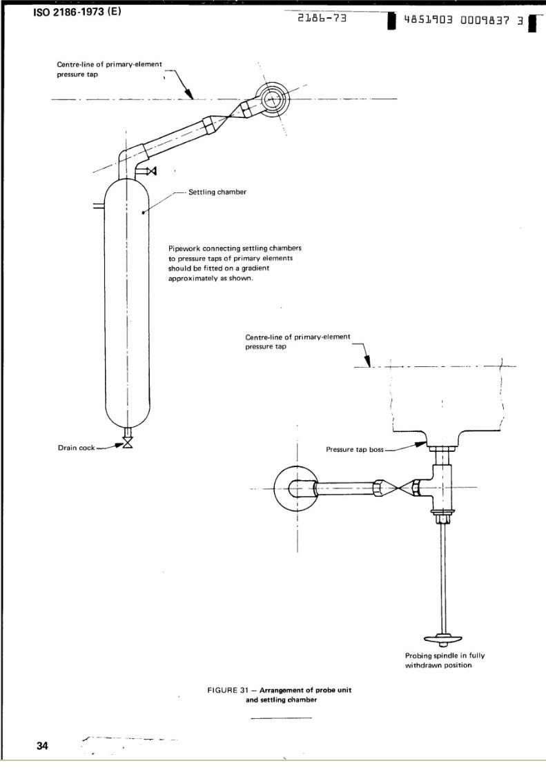
As a guide to the design of a probe unit, Figure 30 shows a form of probe in comm on use. Figu re 31 shows a typical
installation that includes both probe units and settling chambers.
- - - ---- ---
32 -...•
-
~
-.. .. . . . . .
5/10/2018 ISO 2186-1973 - slidepdf.com
http://slidepdf.com/reader/full/iso-2186-1973 35/36
2186-73 4851903 0009836 1ISO 2186-1973 (E)
I
Q.--0.Cco
: : : c
i
I
I
Q)
--0e-11
Q.
I
U)
Q)
.c0'-e,
c0..-.. . . .- -n
[
0c.e3 :
. . . .1
m
C
I-
::J
-c,Z!
Gl
. . .~
.-3 :
0. . . .
>
e,
-I
-: : : I. . . 0
C
M
I-
f-
W
.-C C
c::>
= 'Q)
<9
.. a
-,0. . . .e, •
•
mC
. . . . . . ...-c:::J
OJ
.0oL-
Q_
..
III\,'-~~-.
..
/ -- - -- - - - - -----------. p
- -~ -- "'-~ 33
5/10/2018 ISO 2186-1973 - slidepdf.com
http://slidepdf.com/reader/full/iso-2186-1973 36/36
ISO 2186-1973 (E)2186-73 4851903 0009837 3
Centre-I ine of pri mary-element1
,ressure tap
---- ---- ---------- -- .---- ._--
""
-
-..
11
~---- Settl ing chamber/'
I
I
t
I·
-
~.-
)I
r'\
II1
Pipework connecting settling chambers
to pressure taps of primary elements
should be fitted on a gradient
approximately as shown.
•,I
I
t•
Centre-line of primary-element.__.....
pressure tap
r
·_- , .. . -----
•---~- -
1I --•,,,I
I,-
•
\
II•
Pressure tap boss----I
r
•II
·•
Probing spindle in fully
withdrawn position
..FIGURE 31 - Arrangement of probe unit
and settl ing chamber
r---~ -- -- . . . . . . . . . --- . . . . . . . . . . . . . . . . . . . . . . --
34 ...
.. ....•