iso 13500 (e)
TRANSCRIPT
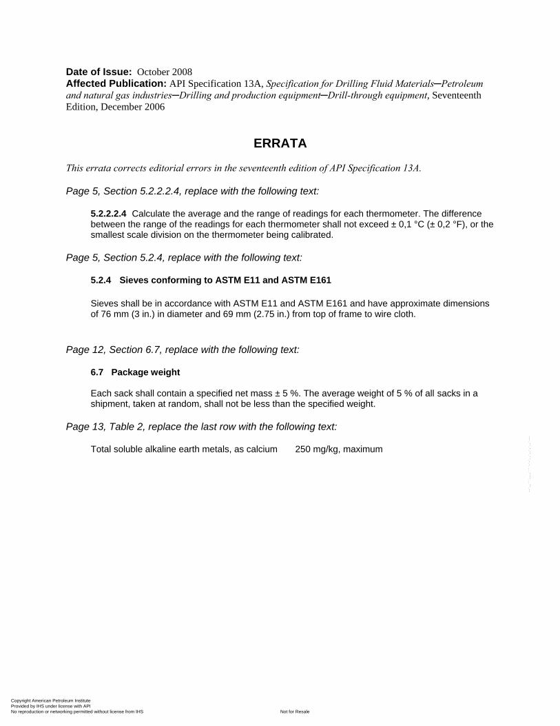
Date of Issue: October 2008 Affected Publication: API Specification 13A, Specification for Drilling Fluid Materials─Petroleum and natural gas industries─Drilling and production equipment─Drill-through equipment, Seventeenth Edition, December 2006
ERRATA This errata corrects editorial errors in the seventeenth edition of API Specification 13A. Page 5, Section 5.2.2.2.4, replace with the following text:
5.2.2.2.4 Calculate the average and the range of readings for each thermometer. The difference between the range of the readings for each thermometer shall not exceed ± 0,1 °C (± 0,2 °F), or the smallest scale division on the thermometer being calibrated.
Page 5, Section 5.2.4, replace with the following text:
5.2.4 Sieves conforming to ASTM E11 and ASTM E161
Sieves shall be in accordance with ASTM E11 and ASTM E161 and have approximate dimensions of 76 mm (3 in.) in diameter and 69 mm (2.75 in.) from top of frame to wire cloth.
Page 12, Section 6.7, replace with the following text:
6.7 Package weight Each sack shall contain a specified net mass ± 5 %. The average weight of 5 % of all sacks in a shipment, taken at random, shall not be less than the specified weight.
Page 13, Table 2, replace the last row with the following text:
Total soluble alkaline earth metals, as calcium 250 mg/kg, maximum
Copyright American Petroleum Institute Provided by IHS under license with API
Not for ResaleNo reproduction or networking permitted without license from IHS
--`,,```,,,,````-`-`,,`,,`,`,,`---
Specification for Drilling-Fluid Materials
ANSI/API SPECIFICATION 13A SEVENTEENTH EDITION, NOVEMBER 2006
EFFECTIVE DATE: MAY 1, 2007
ERRATA, OCTOBER 2008
ISO 13500:2006 (Identical), Petroleum and natural gas industries—Drilling Fluid Materials—Specifications and tests
Copyright American Petroleum Institute Provided by IHS under license with API
Not for ResaleNo reproduction or networking permitted without license from IHS
--`,,```,,,,````-`-`,,`,,`,`,,`---

Copyright American Petroleum Institute Provided by IHS under license with API
Not for ResaleNo reproduction or networking permitted without license from IHS
--`,,```,,,,````-`-`,,`,,`,`,,`---
Special Notes
API publications necessarily address problems of a general nature. With respect to particular circumstances, local, state, and federal laws and regulations should be reviewed.
Neither API nor any of API’s employees, subcontractors, consultants, committees, or other assignees make any warranty or representation, either express or implied, with respect to the accuracy, completeness, or usefulness of the information contained herein, or assume any liability or responsibility for any use, or the results of such use, of any information or process disclosed in this publication. Neither API nor any of API’s employees, subcontractors, consultants, or other assignees represent that use of this publication would not infringe upon privately owned rights.
API publications may be used by anyone desiring to do so. Every effort has been made by the Institute to assure the accuracy and reliability of the data contained in them; however, the Institute makes no representation, warranty, or guarantee in connection with this publication and hereby expressly disclaims any liability or responsibility for loss or damage resulting from its use or for the violation of any authorities having jurisdiction with which this publication may conflict.
API publications are published to facilitate the broad availability of proven, sound engineering and operating practices. These publications are not intended to obviate the need for applying sound engineering judgment regarding when and where these publications should be utilized. The formulation and publication of API publications is not intended in any way to inhibit anyone from using any other practices.
Any manufacturer marking equipment or materials in conformance with the marking requirements of an API standard is solely responsible for complying with all the applicable requirements of that standard. API does not represent, warrant, or guarantee that such products do in fact conform to the applicable API standard.
All rights reserved. No part of this work may be reproduced, stored in a retrieval system, or transmitted by any means, electronic, mechanical, photocopying, recording, or otherwise, without
prior written permission from the publisher. Contact the Publisher, API Publishing Services, 1220 L Street, N.W., Washington, D.C. 20005.
Copyright © 2006, 2008 American Petroleum Institute
Copyright American Petroleum Institute Provided by IHS under license with API
Not for ResaleNo reproduction or networking permitted without license from IHS
--`,,```,,,,````-`-`,,`,,`,`,,`---
API Foreword
Nothing contained in any API publication is to be construed as granting any right, by implication or otherwise, for the manufacture, sale, or use of any method, apparatus, or product covered by letters patent. Neither should anything contained in the publication be construed as insuring anyone against liability for infringement of letters patent.
This document was produced under API standardization procedures that ensure appropriate notification and participation in the developmental process and is designated as an API standard. Questions concerning the interpretation of the content of this publication or comments and questions concerning the procedures under which this publication was developed should be directed in writing to the Director of Standards, American Petroleum Institute, 1220 L Street, N.W., Washington, D.C. 20005. Requests for permission to reproduce or translate all or any part of the material published herein should also be addressed to the director.
Generally, API standards are reviewed and revised, reaffirmed, or withdrawn at least every five years. A one-time extension of up to two years may be added to this review cycle. Status of the publication can be ascertained from the API Standards Department, telephone (202) 682-8000. A catalog of API publications and materials is published annually and updated quarterly by API, 1220 L Street, N.W., Washington, D.C. 20005.
Suggested revisions are invited and should be submitted to the Standards and Publications Department, API, 1220 L Street, NW, Washington, DC 20005, [email protected].
This standard shall become effective on the date printed on the cover but may be used voluntarily from the date of distribution.
Standards referenced herein may be replaced by other international or national standards that can be shown to meet or exceed the requirements of the referenced standard.
This American National Standard is under the jurisdiction of API Subcommittee 13 on Drilling, Completion, and Fracturing Fluid. This standard is considered identical to the English version of ISO 13500:2006. ISO 13500:2006 was prepared by Technical Committee ISO/TC 67/SC3.
The following editorial change has been incorporated into this standard:
Table 2, Total soluble alkaline earth metals, as calcium; Maximum 250 mg/KG
Copyright American Petroleum Institute Provided by IHS under license with API
Not for ResaleNo reproduction or networking permitted without license from IHS
--`,,```,,,,````-`-`,,`,,`,`,,`---

Copyright American Petroleum Institute Provided by IHS under license with API
Not for ResaleNo reproduction or networking permitted without license from IHS
--`,,```,,,,````-`-`,,`,,`,`,,`---
API Spec 13A / ISO 13500
ii
Contents Page
API Foreword ...................................................................................................................................................... ii
Foreword ............................................................................................................................................................. v Introduction ....................................................................................................................................................... vi 1 Scope ..................................................................................................................................................... 1 2 Normative references ........................................................................................................................... 1 3 Terms, definitions, symbols and abbreviations ................................................................................ 1 3.1 Terms and definitions........................................................................................................................... 1 3.2 Symbols and abbreviations ................................................................................................................. 2 4 Requirements ........................................................................................................................................ 4 4.1 Quality control instructions ................................................................................................................. 4 4.2 Use of test calibration materials in checking testing procedures ................................................... 4 4.3 Records retention ................................................................................................................................. 4 5 Calibration ............................................................................................................................................. 4 5.1 Coverage ................................................................................................................................................ 4 5.2 Equipment requiring calibration ......................................................................................................... 5 5.3 Calibration intervals ............................................................................................................................. 9 6 Packaged material .............................................................................................................................. 11 6.1 Description .......................................................................................................................................... 11 6.2 Apparatus — Pallets ........................................................................................................................... 11 6.3 Apparatus — Bags .............................................................................................................................. 11 6.4 Marking — Pallets ............................................................................................................................... 11 6.5 Marking — Bags .................................................................................................................................. 12 6.6 Pallet covers ........................................................................................................................................ 12 6.7 Package weight ................................................................................................................................... 12 6.8 Storage ................................................................................................................................................. 12 6.9 Recycling ............................................................................................................................................. 12 7 Barite .................................................................................................................................................... 13 7.1 Principle ............................................................................................................................................... 13 7.2 Reagents and apparatus — Density by Le Chatelier flask ............................................................. 13 7.3 Procedure — Density by Le Chatelier flask ..................................................................................... 14 7.4 Calculation — Density by Le Chatelier flask .................................................................................... 15 7.5 Reagents and apparatus — Water-soluble alkaline earths as calcium ......................................... 15 7.6 Procedure — Water-soluble alkaline earth metals as calcium ...................................................... 16 7.7 Calculation — Water-soluble alkaline earths as calcium ............................................................... 16 7.8 Reagents and materials — Residue of diameter greater than 75 µm ............................................ 16 7.9 Procedure — Residue of diameter greater than 75 µm ................................................................... 17 7.10 Calculation — Residue of diameter greater than 75 µm ................................................................. 17 7.11 Reagents and apparatus — Particles less than 6 µm in equivalent spherical diameter
by sedimentation method .................................................................................................................. 18 7.12 Procedure — Particles less than 6 µm in equivalent spherical diameter by sedimentation
method ................................................................................................................................................. 18 7.13 Calculation — Particles less than 6 µm in equivalent spherical diameter by sedimentation
method ................................................................................................................................................. 19 8 Haematite (hematite) ............................................................................................................................ 22 8.1 Principle ............................................................................................................................................... 22
Copyright American Petroleum Institute Provided by IHS under license with API
Not for ResaleNo reproduction or networking permitted without license from IHS
--`,,```,,,,````-`-`,,`,,`,`,,`---
API Spec 13A / ISO 13500
iii
8.2 Reagent and apparatus — Density by Le Chatelier flask ................................................................ 23 8.3 Procedure — Density by Le Chatelier flask ...................................................................................... 23 8.4 Calculation — Density by Le Chatelier flask .................................................................................... 24 8.5 Reagents and apparatus — Water-soluble alkaline earth metals as calcium ............................... 24 8.6 Procedure — Water-soluble alkaline earth metals as calcium ....................................................... 25 8.7 Calculation — Water-soluble alkaline earth metals as calcium ...................................................... 26 8.8 Reagents and apparatus — Residues greater that 75 µm and 45 µm ............................................ 26 8.9 Procedure — Residues of diameter greater than 75 µm and 45 µm ............................................... 26 8.10 Calculation — Residues of diameter greater than 75 µm and 45 µm ............................................. 27 8.11 Reagents and apparatus — Particles less than 6 µm in equivalent spherical diameter
by sedimentation method ................................................................................................................... 27 8.12 Procedure — Particles less than 6 µm in equivalent spherical diameter by sedimentation
method .................................................................................................................................................. 28 8.13 Calculation — Particles less than 6 µm in equivalent spherical diameter by sedimentation
method .................................................................................................................................................. 29 9 Bentonite .............................................................................................................................................. 31 9.1 Principle ................................................................................................................................................ 31 9.2 Reagents and apparatus — Suspension properties ........................................................................ 31 9.3 Procedure — Rheology of suspension ............................................................................................. 32 9.4 Calculation — Rheology of suspension ............................................................................................ 32 9.5 Procedure — Filtrate volume of suspension .................................................................................... 33 9.6 Calculation — Filtrate volume of suspension .................................................................................. 33 9.7 Reagents and apparatus — Residue of diameter greater than 75 µm ........................................... 33 9.8 Procedure — Residue of diameter greater than 75 µm ................................................................... 34 9.9 Calculation — Residue of diameter greater than 75 µm .................................................................. 34 10 Non-treated bentonite ......................................................................................................................... 34 10.1 Principle ................................................................................................................................................ 34 10.2 Reagents and apparatus — Suspension properties ........................................................................ 35 10.3 Procedure — Rheology of suspension ............................................................................................. 35 10.4 Calculation — Rheology of suspension ............................................................................................ 36 10.5 Procedure — Dispersed plastic viscosity of suspension ............................................................... 36 10.6 Procedure — Dispersed filtrate volume of suspension .................................................................. 36 10.7 Calculation — Dispersed filtrate volume of suspension ................................................................. 36 11 OCMA grade bentonite ........................................................................................................................ 37 11.1 Principle ................................................................................................................................................ 37 11.2 Reagents and apparatus — Suspension properties ........................................................................ 37 11.3 Procedure — Rheology of suspension ............................................................................................. 38 11.4 Calculation — Rheology of suspension ............................................................................................ 38 11.5 Procedure — Filtrate volume of suspension .................................................................................... 38 11.6 Calculation — Filtrate volume of suspension .................................................................................. 39 11.7 Reagents and apparatus — Residue of diameter greater than 75 µm ........................................... 39 11.8 Procedure — Residue of diameter greater than 75 µm ................................................................... 39 11.9 Calculation — Residue of diameter greater than 75 µm .................................................................. 40 12 Attapulgite ............................................................................................................................................ 40 12.1 Principle ................................................................................................................................................ 40 12.2 Reagents and apparatus — Suspension properties ........................................................................ 40 12.3 Procedure — 600 r/min dial reading of suspension ........................................................................ 41 12.4 Reagent and apparatus — Residue of diameter greater than 75 µm ............................................. 41 12.5 Procedure — Residue of diameter greater than 75 µm ................................................................... 42 12.6 Calculation — Residue of diameter greater than 75 µm .................................................................. 42 12.7 Reagent and apparatus — Moisture .................................................................................................. 42 12.8 Procedure — Moisture ........................................................................................................................ 43 12.9 Calculation — Moisture ....................................................................................................................... 43 13 Sepiolite ................................................................................................................................................ 43
Copyright American Petroleum Institute Provided by IHS under license with API
Not for ResaleNo reproduction or networking permitted without license from IHS
--`,,```,,,,````-`-`,,`,,`,`,,`---
API Spec 13A / ISO 13500
iv
13.1 Principle ............................................................................................................................................... 43 13.2 Reagents and apparatus — Suspension properties ....................................................................... 43 13.3 Procedure — 600 r/min dial reading of suspension ........................................................................ 44 13.4 Reagents and apparatus — Residue of diameter greater than 75 µm ........................................... 44 13.5 Procedure — Residue of diameter greater than 75 µm ................................................................... 45 13.6 Calculation — Residue of diameter greater than 75 µm ................................................................. 45 13.7 Reagents and apparatus — Moisture ............................................................................................... 45 13.8 Procedure — Moisture........................................................................................................................ 46 13.9 Calculation — Moisture ...................................................................................................................... 46 14 Technical grade low-viscosity CMC (CMC-LVT) .............................................................................. 46 14.1 Principle ............................................................................................................................................... 46 14.2 Reagents and apparatus — Determination of starch and starch derivatives............................... 47 14.3 Procedure — Determination of starch and starch derivatives ....................................................... 47 14.4 Interpretation — Determination of starch and starch derivatives ................................................. 48 14.5 Reagents and apparatus — Solution properties of water-soluble polymers ............................... 48 14.6 Procedure — Viscometer reading in deionized water ..................................................................... 49 14.7 Procedure — Filtrate volume of solution ......................................................................................... 49 14.8 Calculation — Filtrate volume of solution ........................................................................................ 50 15 Technical grade high-viscosity CMC (CMC-HVT) ............................................................................ 50 15.1 Principle ............................................................................................................................................... 50 15.2 Reagents and apparatus — Determination of starch and starch derivatives............................... 51 15.3 Procedure — Determination of starch and starch derivatives ....................................................... 51 15.4 Interpretation — Determination of starch and starch derivatives ................................................. 52 15.5 Reagents and apparatus — Solution properties of water-soluble polymers ............................... 52 15.6 Procedure — Viscometer reading in deionized water ..................................................................... 53 15.7 Procedure — Viscometer reading in 40 g/l salt water ..................................................................... 54 15.8 Procedure — Viscometer reading in saturated salt water .............................................................. 54 15.9 Procedure — Filtrate volume of solution ......................................................................................... 55 15.10 Calculation — Filtrate volume of solution ........................................................................................ 55 16 Starch ................................................................................................................................................... 56 16.1 Principle ............................................................................................................................................... 56 16.2 Reagents and apparatus — Suspension properties ....................................................................... 56 16.3 Procedure — Viscometer reading in 40 g/l salt water ..................................................................... 57 16.4 Procedure — Filtrate volume of 40 g/l salt solution ........................................................................ 58 16.5 Calculation — Filtrate volume of 40 g/l salt solution ...................................................................... 58 16.6 Procedure — Viscometer reading in saturated salt solution ......................................................... 58 16.7 Procedure — Filtrate volume of saturated salt solution ................................................................. 59 16.8 Calculation — Filtrate volume of saturated salt solution ............................................................... 59 16.9 Reagents and apparatus — Residue greater than 2 000 µm .......................................................... 59 16.10 Procedure — Residue greater than 2 000 µm .................................................................................. 59 Annex A (informative) Mineral impurities in barite ....................................................................................... 60 Annex B (informative) Test precision ............................................................................................................. 61 Annex C (informative) Examples of calculations .......................................................................................... 66
Annex D (informative) API Monogram .............................................................................................................. 75
Bibliography ....................................................................................................................................................... 76
Copyright American Petroleum Institute Provided by IHS under license with API
Not for ResaleNo reproduction or networking permitted without license from IHS
--`,,```,,,,````-`-`,,`,,`,`,,`---
API Spec 13A / ISO 13500
v
Foreword
ISO (the International Organization for Standardization) is a worldwide federation of national standards bodies (ISO member bodies). The work of preparing International Standards is normally carried out through ISO technical committees. Each member body interested in a subject for which a technical committee has been established has the right to be represented on that committee. International organizations, governmental and non-governmental, in liaison with ISO, also take part in the work. ISO collaborates closely with the International Electrotechnical Commission (IEC) on all matters of electrotechnical standardization.
International Standards are drafted in accordance with the rules given in the ISO/IEC Directives, Part 2.
The main task of technical committees is to prepare International Standards. Draft International Standards adopted by the technical committees are circulated to the member bodies for voting. Publication as an International Standard requires approval by at least 75 % of the member bodies casting a vote.
Attention is drawn to the possibility that some of the elements of this document may be the subject of patent rights. ISO shall not be held responsible for identifying any or all such patent rights.
ISO 13500 was prepared by Technical Committee ISO/TC 67, Materials, equipment and offshore structures for petroleum, petrochemical and natural gas industries, Subcommittee SC 3, Drilling and completion fluids, and well cements.
This second edition cancels and replaces the first edition (ISO 13500:1998), which has been technically revised.
Copyright American Petroleum Institute Provided by IHS under license with API
Not for ResaleNo reproduction or networking permitted without license from IHS
--`,,```,,,,````-`-`,,`,,`,`,,`---
API Spec 13A / ISO 13500
vi
Introduction
This International Standard covers materials which are in common usage in petroleum and natural gas drilling fluids. These materials are used in bulk quantities, can be purchased from multiple sources, and are available as commodity products. No single-source or limited-source products are included, nor are speciality products.
International Standards are published to facilitate communication between purchasers and manufacturers, to provide interchangeability between similar equipment and materials purchased from different manufacturers and/or at different times, and to provide an adequate level of safety when the equipment or materials are utilised in the manner and for the purposes intended. This International Standard provides minimum requirements and is not intended to inhibit anyone from purchasing or producing materials to other standards.
This International Standard is substantially based on API Spec 13A, 16th Edition, December 1, 2003. The purpose of this International Standard is to provide product specifications for barite, haematite, bentonite, nontreated bentonite, Oil Companies Materials Association (OCMA) grade bentonite, attapulgite, sepiolite, technical-grade low viscosity carboxymethylcellulose (CMC-LVT), technical-grade high viscosity carboxymethylcellulose (CMC-HVT), and starch.
The intent of the document was to incorporate all International Standards for drilling fluid materials into an ISO-formatted document. A survey of the industry found that only the American Petroleum Institute (API) issued testing procedures and specification standards for these materials.
Reference to OCMA materials has been included in API work, as the OCMA and subsequent holding committees were declared defunct, and all specifications were submitted to API in 1983.
Annex A (informative) lists the mineral impurities in barite, Annex B (informative) provides the test precision and Annex C (informative) details examples of calculations.
Copyright American Petroleum Institute Provided by IHS under license with API
Not for ResaleNo reproduction or networking permitted without license from IHS
--`,,```,,,,````-`-`,,`,,`,`,,`---
1
Petroleum and natural gas industries — Drilling fluid materials — Specifications and tests
1 Scope
This International Standard covers physical properties and test procedures for materials manufactured for use in oil- and gas-well drilling fluids. The materials covered are barite, haematite, bentonite, nontreated bentonite, OCMA grade bentonite, attapulgite, sepiolite, technical grade low-viscosity carboxymethylcellulose (CMC-LVT), technical grade high-viscosity carboxymethylcellulose (CMC-HVT), and starch. This International Standard is intended for the use of manufacturers of named products.
2 Normative references
The following referenced documents are indispensable for the application of this document. For dated references, only the edition cited applies. For undated references, the latest edition of the referenced document (including any amendments) applies.
ISO 6780, Flat pallets for intercontinental materials handling — Principal dimensions and tolerances
ISO 10414-1, Petroleum and natural gas industries — Field testing of drilling fluids — Part 1: Water-based fluids
ASTM D422, Standard Test Method for Particle-Size Analysis of Soils
ASTM E11, Standard Specification for Wire Cloth and Sieves for Testing Purposes
ASTM E161, Standard Specification for Precision Electroformed Sieves
ASTM E77, Standard Test Method for Inspection and Verification of Thermometers
ASTM E177, Standard Practice for Use of the Terms Precision and Bias in ASTM Test Methods
NIST (NBS) Monograph 150, Liquid-in-glass thermometry
3 Terms, definitions, symbols and abbreviations
3.1 Terms and definitions
For the purposes of this document, the following terms and definitions apply.
3.1.1 ACS reagent grade chemicals which meet purity standards as specified by the American Chemical Society (ACS)
3.1.2 flash side side containing residue (“flash”) from stamping, or the side with concave indentation
Copyright American Petroleum Institute Provided by IHS under license with API
Not for ResaleNo reproduction or networking permitted without license from IHS
--`,,```,,,,````-`-`,,`,,`,`,,`---
API Spec 13A / ISO 13500
2
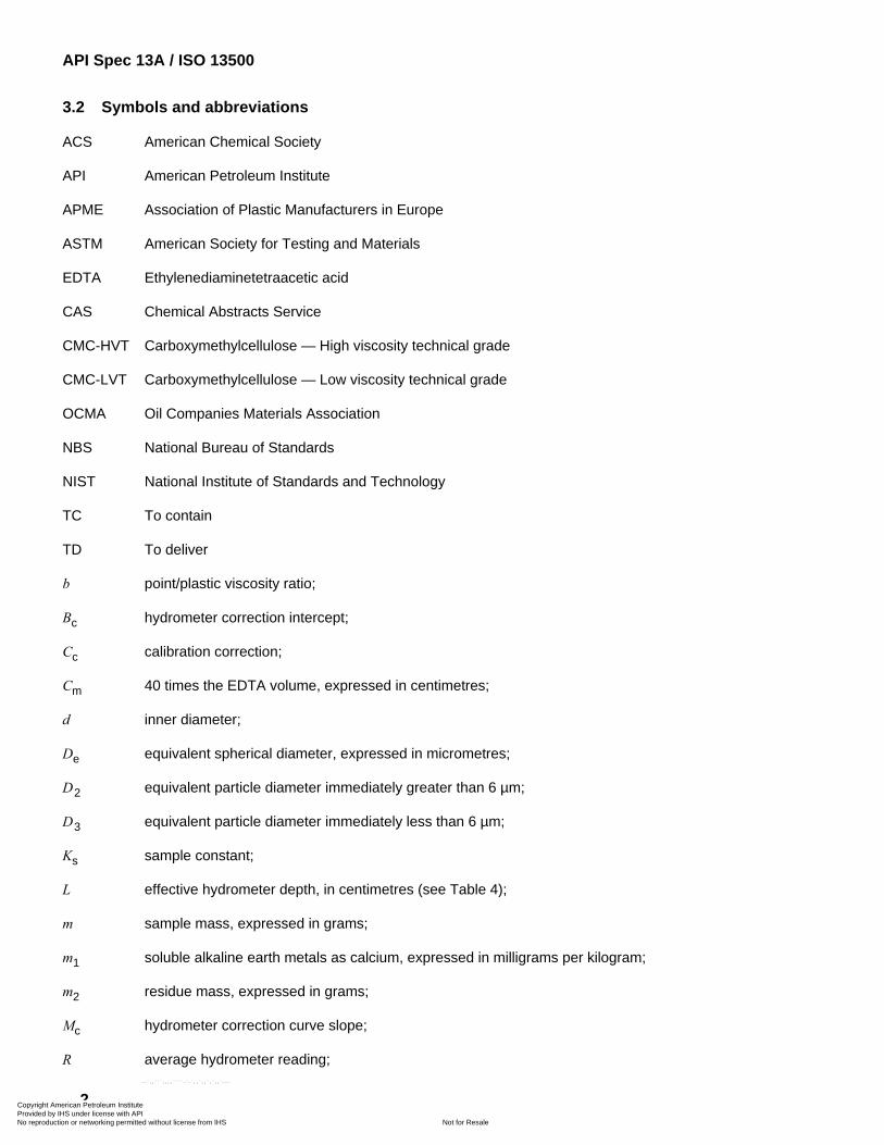
3.2 Symbols and abbreviations
ACS American Chemical Society
API American Petroleum Institute
APME Association of Plastic Manufacturers in Europe
ASTM American Society for Testing and Materials
EDTA Ethylenediaminetetraacetic acid
CAS Chemical Abstracts Service
CMC-HVT Carboxymethylcellulose — High viscosity technical grade
CMC-LVT Carboxymethylcellulose — Low viscosity technical grade
OCMA Oil Companies Materials Association
NBS National Bureau of Standards
NIST National Institute of Standards and Technology
TC To contain
TD To deliver
b point/plastic viscosity ratio;
Bc hydrometer correction intercept;
Cc calibration correction;
Cm 40 times the EDTA volume, expressed in centimetres;
d inner diameter;
De equivalent spherical diameter, expressed in micrometres;
D2 equivalent particle diameter immediately greater than 6 µm;
D3 equivalent particle diameter immediately less than 6 µm;
Ks sample constant;
L effective hydrometer depth, in centimetres (see Table 4);
m sample mass, expressed in grams;
m1 soluble alkaline earth metals as calcium, expressed in milligrams per kilogram;
m2 residue mass, expressed in grams;
Mc hydrometer correction curve slope;
R average hydrometer reading;
Copyright American Petroleum Institute Provided by IHS under license with API
Not for ResaleNo reproduction or networking permitted without license from IHS
--`,,```,,,,````-`-`,,`,,`,`,,`---
API Spec 13A / ISO 13500
3
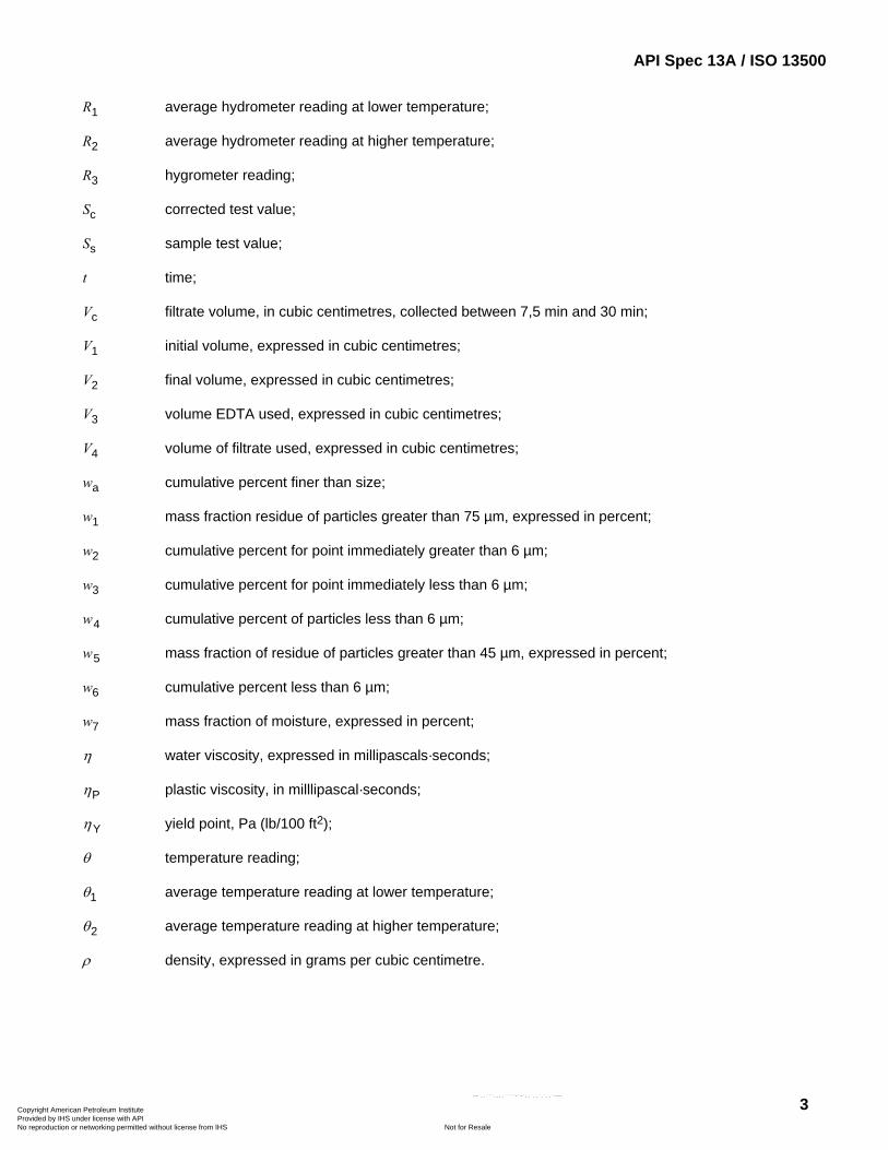
R1 average hydrometer reading at lower temperature;
R2 average hydrometer reading at higher temperature;
R3 hygrometer reading;
Sc corrected test value;
Ss sample test value;
t time;
Vc filtrate volume, in cubic centimetres, collected between 7,5 min and 30 min;
V1 initial volume, expressed in cubic centimetres;
V2 final volume, expressed in cubic centimetres;
V3 volume EDTA used, expressed in cubic centimetres;
V4 volume of filtrate used, expressed in cubic centimetres;
wa cumulative percent finer than size;
w1 mass fraction residue of particles greater than 75 µm, expressed in percent;
w2 cumulative percent for point immediately greater than 6 µm;
w3 cumulative percent for point immediately less than 6 µm;
w4 cumulative percent of particles less than 6 µm;
w5 mass fraction of residue of particles greater than 45 µm, expressed in percent;
w6 cumulative percent less than 6 µm;
w7 mass fraction of moisture, expressed in percent;
η water viscosity, expressed in millipascals·seconds;
ηP plastic viscosity, in milllipascal·seconds;
ηY yield point, Pa (lb/100 ft2);
θ temperature reading;
θ1 average temperature reading at lower temperature;
θ2 average temperature reading at higher temperature;
ρ density, expressed in grams per cubic centimetre.
Copyright American Petroleum Institute Provided by IHS under license with API
Not for ResaleNo reproduction or networking permitted without license from IHS
--`,,```,,,,````-`-`,,`,,`,`,,`---
API Spec 13A / ISO 13500
4
4 Requirements
4.1 Quality control instructions
All quality control work shall be controlled by manufacturer's documented instructions, which include appropriate methodology and quantitative or qualitative acceptance criteria.
4.2 Use of test calibration materials in checking testing procedures
4.2.1 Test Calibration Barite and Test Calibration Bentonite can be obtained by contacting the API 1 ). The calibration test materials are shipped in a 7,6 l (2 gal) plastic container.
4.2.2 The API office will forward the request to the designated custodian for further handling. The test calibration products is furnished with a certificate of calibration giving the established values for each property and the confidence limits within which a laboratory's results shall fall.
4.2.3 The custodian shall furnish a certificate of analysis for each sample.
4.2.4 For calibration requirements of API test calibration materials, refer to 5.2.11 and 5.3.10.
4.2.5 API standard evaluation base clay (formerly OCMA base clay; not OCMA grade bentonite): stocks of API standard evaluation base clay have been set aside and can be ordered through the API.
4.3 Records retention
All records specified in this International Standard shall be maintained for a minimum of five years from the date of preparation.
5 Calibration
5.1 Coverage
5.1.1 Clause 5 covers calibration procedures and calibration intervals for laboratory equipment and reagents specified. For laboratory items not listed, the manufacturer shall develop procedures where deemed appropriate.
5.1.2 The manufacturer shall control, calibrate, verify, and maintain the laboratory equipment and reagents used in this International Standard for measuring product conformance to International Standard requirements.
5.1.3 The manufacturer shall maintain and use laboratory equipment and reagents in a manner such that measurement uncertainty is known and meets required measurement capability.
5.1.4 The manufacturer shall document and maintain calibration procedures, including details of laboratory equipment and reagent type, identification number, frequency of checks, acceptance criteria, and corrective action to be taken when results are unsatisfactory.
5.1.5 The manufacturer shall establish and document responsibility for administration of the calibration program, and responsibility for corrective action.
5.1.6 The manufacturer shall document and maintain calibration records for laboratory equipment and reagents; shall periodically review these records for trends, sudden shifts or other signals of approaching malfunction; and shall identify each item with a suitable indicator or approved identification record to show calibration status.
1) American Petroleum Institute, 1220 L Street NW, Washington, D.C. 20005-4070, USA.
Copyright American Petroleum Institute Provided by IHS under license with API
Not for ResaleNo reproduction or networking permitted without license from IHS
--`,,```,,,,````-`-`,,`,,`,`,,`---
API Spec 13A / ISO 13500
5
5.2 Equipment requiring calibration
5.2.1 Volumetric glassware
Laboratory volumetric glassware used for final acceptance, including Le Chatelier flasks, pipettes, and burettes, are usually calibrated by the supplier. Manufacturers of products to this International Standard shall document evidence of glassware calibration prior to use. Supplier certification is acceptable. Calibration may be checked gravimetrically. Periodic recalibration is not required.
5.2.2 Laboratory thermometers
5.2.2.1 The manufacturer shall calibrate all laboratory thermometers used in measuring product conformance to standards against a secondary reference thermometer. The secondary reference thermometer shall show evidence of calibration as performed against NIST certified master instruments, in accordance with the procedures outlined by ASTM E77 and NBS (NIST) Monograph 150.
5.2.2.2 Calibration — Thermometers
5.2.2.2.1 Place thermometer to be calibrated side by side with secondary reference thermometer into a constant-temperature water bath (or suitable container of 4 l or more, filled with water, on a counter in a constant-temperature room) and allow to equilibrate for at least 1 h.
5.2.2.2.2 Read both thermometers and record readings.
5.2.2.2.3 Repeat readings throughout at least a 1-h interval to obtain a minimum of four readings.
5.2.2.2.4 Calculate the average and the range of readings for each thermometer. The difference between the range of the readings for each thermometer shall not exceed ± 0,1 °C (± 0,2 °F), or the smallest scale division on the thermometer being calibrated.
5.2.2.2.5 Calculate average deviation of thermometer reading from secondary reference thermometer reading. Calculate and document correction for each thermometer.
5.2.3 Laboratory balances
5.2.3.1 The manufacturer shall calibrate laboratory balances periodically in the range of use with NIST class P, grade 3, or better weights.
5.2.3.2 The manufacturer shall service and adjust balances whenever calibration indicates a problem.
5.2.4 Sieves conforming to ASTM E11 and ASTM E161
Sieves shall be in accordance with ASTM E11 and ASTM E161 and have approximate dimensions of 76 mm (3 in.) in diameter and 69 mm (2.75 in.) from top of frame to wire cloth.
5.2.5 Hydrometer
5.2.5.1 The manufacturer shall calibrate each hydrometer with the dispersant solution used in the sedimentation procedure.
5.2.5.2 Calibration — Hydrometer
5.2.5.2.1 Calibrate each hydrometer to be used using the same concentration dispersant solution as is used in the test, at temperatures spanning the anticipated test temperatures, and by reading the top rather than the bottom of the meniscus. Calibrate each hydrometer using the procedure below.
Copyright American Petroleum Institute Provided by IHS under license with API
Not for ResaleNo reproduction or networking permitted without license from IHS
--`,,```,,,,````-`-`,,`,,`,`,,`---
API Spec 13A / ISO 13500
6
5.2.5.2.2 Prepare 1 l of dispersant solution, as follows.
a) Place 125 cm3 ± 2 cm3 (125 g ± 2 g) of dispersant solution from test procedure [7.11 a)] into a 1-l volumetric flask.
b) Dilute to the 1 000-cm3 mark with deionized water. Mix thoroughly.
5.2.5.2.3 Place the dispersant solution in a sedimentation cylinder. Then place the cylinder in a constant-temperature bath. Set bath temperature to the lowest expected temperature for any actual test. Allow to reach equilibrium ± 0,2 °C. Insert the hydrometer to be calibrated and wait at least 5 min for the hydrometer and solution to reach bath temperature.
5.2.5.2.4 Take a hydrometer reading at the top of the meniscus formed by the stem and take a thermometer reading. Repeat readings at least 5 min apart so as to obtain a minimum of four readings each.
5.2.5.2.5 Calculate the average hydrometer reading and designate as R1. Calculate the average temperature reading and designate as θ1.
5.2.5.2.6 Repeat 5.2.5.2.3 through 5.2.5.2.4 except set bath temperature to highest expected test temperature, calculate average hydrometer and temperature readings, and designate these readings as R2 and θ2.
5.2.5.2.7 Calculate the hydrometer correction curve slope, Mc, as given in Equation (1):
( )( )
1 2c
2 11000
R RM
θ θ−
=−
(1)
where
R1 is the average hydrometer reading at lower temperature;
R2 is the average hydrometer reading at higher temperature;
θ1 is the average temperature reading at lower temperature;
θ2 is the average temperature reading at higher temperature.
Temperature may be measured in either °C or °F, so long as all measurements and calculations are consistent in units (including subsequent use of hydrometer in routine test situations).
5.2.5.2.8 Calculate the hydrometer correction curve intercept, Bc, as given in Equation (2):
( ) ( )c c 1 1 1 1000B M Rθ ⎡= × + − ×⎣ ⎤⎦ (2)
where
Mc is the hydrometer correction curve slope;
θ1 is the average thermometer reading at lower temperature;
R1 is the average hydrometer reading at lower temperature.
5.2.5.2.9 Record Mc, Bc and hydrometer serial number in permanent calibration record and on the data sheet used in the calculations in 7.13 and 8.13.
For “Hydrometer calibration. Example data sheet and calculation”, see C.1.
Copyright American Petroleum Institute Provided by IHS under license with API
Not for ResaleNo reproduction or networking permitted without license from IHS
--`,,```,,,,````-`-`,,`,,`,`,,`---
API Spec 13A / ISO 13500
7
5.2.6 Motor-driven direct-indicating viscometer
5.2.6.1 The specifications for a direct-indicating viscometer are given in ISO 10414-1 and given here for reference.
a) Rotor sleeve:
⎯ inside diameter: 36,83 mm (1,450 in),
⎯ total length: 87,0 mm (3,425 in),
⎯ scribed line: 58,4 mm (2,30 in) above the bottom of sleeve, with two rows of 3,18 mm (0,125 in) holes spaced 120° (2,09 rad) apart, around rotor sleeve just below scribed line;
b) bob, closed, with flat base and tapered top:
⎯ diameter: 34,49 mm (1,358 in),
⎯ cylinder length: 38,0 mm (1,496 in);
c) torsion spring constant:
⎯ 386 dyne-cm/degree deflection;
d) rotor sleeve speeds:
⎯ high speed: 600 r/min,
⎯ low speed: 300 r/min.
NOTE Other rotor speeds are available in viscometers from various manufacturers.
5.2.6.2 The manufacturer shall calibrate each meter with 20 mPa·s and 50 mPa·s, certified standard silicone fluids.
5.2.6.3 Apparatus and materials.
a) Standard thermometer, with an accuracy of ± 0,1 °C, e.g. ASTM 90c or 91c grade.
b) Certified calibration fluid, of viscosity 20 mPa·s, with chart (viscosity vs. temperature).
c) Certified calibration fluid, of viscosity 50 mPa·s, with chart (viscosity vs. temperature).
d) Magnifying glass, approximately ×3 magnification.
5.2.6.4 Procedure.
5.2.6.4.1 Allow the viscometer and the calibration fluids to stand on counter-top a minimum of 2 h to approach temperature equilibrium.
5.2.6.4.2 Operate viscometer without fluid a minimum of 2 min to loosen bearing and gears.
5.2.6.4.3 Clean and dry viscometer cup. Fill the viscometer cup to scribed line with 20 mPa·s calibration fluid and place on meter stage. Raise stage until fluid level is to inscribed line on rotor sleeve.
5.2.6.4.4 Place thermometer into the fluid and hold or tape to the side of viscometer to prevent breakage.
Copyright American Petroleum Institute Provided by IHS under license with API
Not for ResaleNo reproduction or networking permitted without license from IHS
--`,,```,,,,````-`-`,,`,,`,`,,`---
API Spec 13A / ISO 13500
8
5.2.6.4.5 Operate viscometer at 100 r/min setting until thermometer reading is stable to within ± 0,1 °C. Record temperature reading.
5.2.6.4.6 Using magnifying glass, take dial readings at 300 r/min and 600 r/min settings. Estimate readings to nearest 0,5 dial unit and record.
5.2.6.4.7 Compare 300 r/min dial reading to certified viscosity at test temperature from fluid calibration chart. Record readings and deviation from certified calibration fluid viscosity as furnished by supplier. Divide 600 r/min reading by 1,98 to obtain viscosity value at 600 r/min. Compare this value to certified fluid.
5.2.6.4.8 Repeat 5.2.6.4.1, 5.2.6.4.2 through 5.2.6.4.7 using 50 mPa·s fluid.
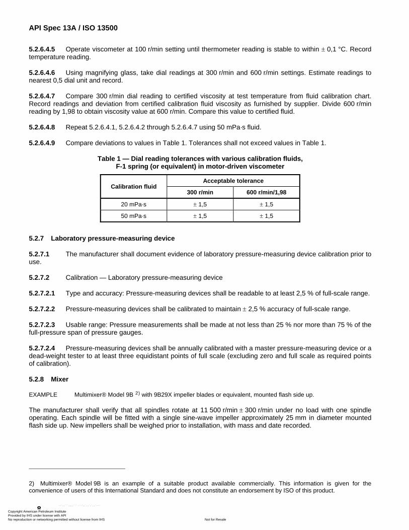
5.2.6.4.9 Compare deviations to values in Table 1. Tolerances shall not exceed values in Table 1.
Table 1 — Dial reading tolerances with various calibration fluids, F-1 spring (or equivalent) in motor-driven viscometer
Calibration fluid Acceptable tolerance
300 r/min 600 r/min/1,98
20 mPa·s ± 1,5 ± 1,5
50 mPa·s ± 1,5 ± 1,5
5.2.7 Laboratory pressure-measuring device
5.2.7.1 The manufacturer shall document evidence of laboratory pressure-measuring device calibration prior to use.
5.2.7.2 Calibration — Laboratory pressure-measuring device
5.2.7.2.1 Type and accuracy: Pressure-measuring devices shall be readable to at least 2,5 % of full-scale range.
5.2.7.2.2 Pressure-measuring devices shall be calibrated to maintain ± 2,5 % accuracy of full-scale range.
5.2.7.2.3 Usable range: Pressure measurements shall be made at not less than 25 % nor more than 75 % of the full-pressure span of pressure gauges.
5.2.7.2.4 Pressure-measuring devices shall be annually calibrated with a master pressure-measuring device or a dead-weight tester to at least three equidistant points of full scale (excluding zero and full scale as required points of calibration).
5.2.8 Mixer
EXAMPLE Multimixer® Model 9B 2) with 9B29X impeller blades or equivalent, mounted flash side up.
The manufacturer shall verify that all spindles rotate at 11 500 r/min ± 300 r/min under no load with one spindle operating. Each spindle will be fitted with a single sine-wave impeller approximately 25 mm in diameter mounted flash side up. New impellers shall be weighed prior to installation, with mass and date recorded.
2) Multimixer® Model 9B is an example of a suitable product available commercially. This information is given for the convenience of users of this International Standard and does not constitute an endorsement by ISO of this product.
Copyright American Petroleum Institute Provided by IHS under license with API
Not for ResaleNo reproduction or networking permitted without license from IHS
--`,,```,,,,````-`-`,,`,,`,`,,`---
API Spec 13A / ISO 13500
9
5.2.9 Chemicals and solutions
5.2.9.1 These shall meet ACS or international equivalent reagent grade, if available.
5.2.9.2 Calibration — EDTA solution
5.2.9.2.1 Reagent
Standard calcium chloride solution, concentration c(CaCl2) = (0,010 0 ± 0,000 1) mol/l.
5.2.9.2.2 Procedure
a) To a suitable flask, add 50 cm3 ± 0,05 cm3 deionized water and 50 cm3 ± 0,05 cm3 of standard CaCl2 solution.
b) Proceed as in 7.6.1 through 7.6.5, but without adding barite or additional water. (Use the 100 cm3 solution prepared above in place of the 100 cm3 deionized water specified in 7.6.1.)
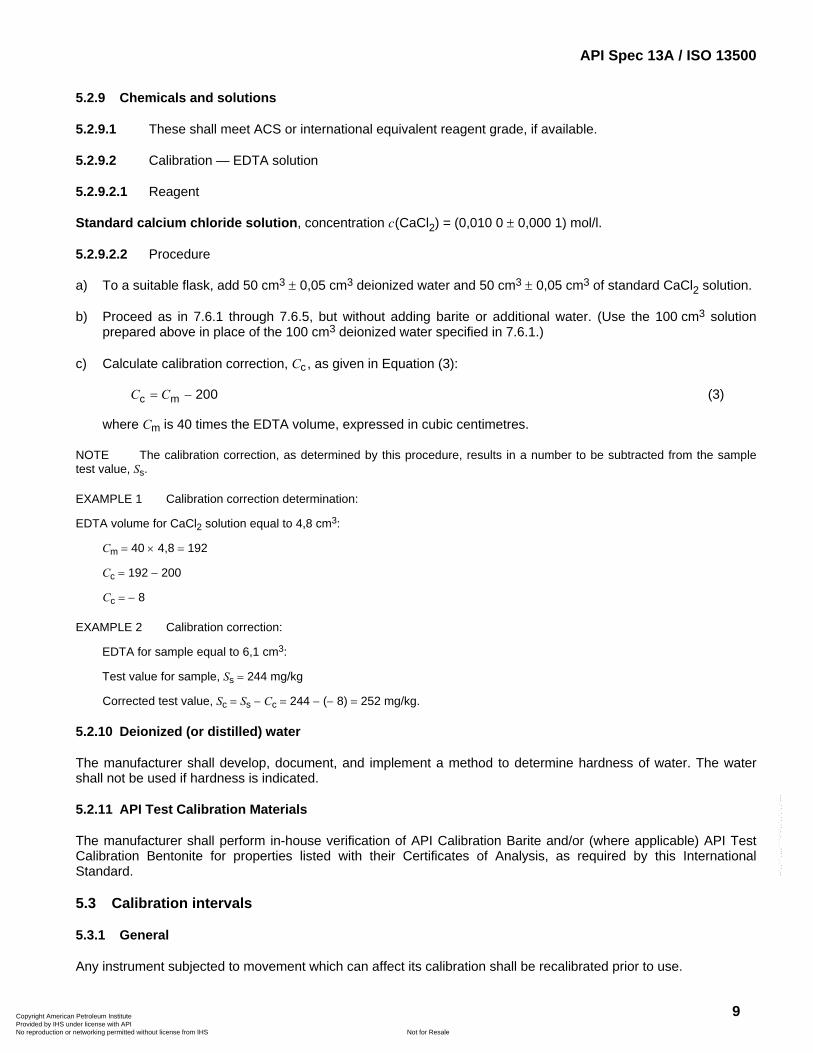
c) Calculate calibration correction, Cc , as given in Equation (3):
200C C= −c m (3)
where Cm is 40 times the EDTA volume, expressed in cubic centimetres.
NOTE The calibration correction, as determined by this procedure, results in a number to be subtracted from the sample test value, Ss.
EXAMPLE 1 Calibration correction determination:
EDTA volume for CaCl2 solution equal to 4,8 cm3:
Cm = 40 × 4,8 = 192
Cc = 192 − 200
Cc = − 8
EXAMPLE 2 Calibration correction:
EDTA for sample equal to 6,1 cm3:
Test value for sample, Ss = 244 mg/kg
Corrected test value, Sc = Ss − Cc = 244 − (− 8) = 252 mg/kg.
5.2.10 Deionized (or distilled) water
The manufacturer shall develop, document, and implement a method to determine hardness of water. The water shall not be used if hardness is indicated.
5.2.11 API Test Calibration Materials
The manufacturer shall perform in-house verification of API Calibration Barite and/or (where applicable) API Test Calibration Bentonite for properties listed with their Certificates of Analysis, as required by this International Standard.
5.3 Calibration intervals
5.3.1 General
Any instrument subjected to movement which can affect its calibration shall be recalibrated prior to use.
Copyright American Petroleum Institute Provided by IHS under license with API
Not for ResaleNo reproduction or networking permitted without license from IHS
--`,,```,,,,````-`-`,,`,,`,`,,`---
API Spec 13A / ISO 13500
10
5.3.2 Thermometers
Calibrate each thermometer before first use by the manufacturer. After calibration, mark each thermometer with an identifying number that ties it to its corresponding correction chart. Check calibration annually against the secondary reference thermometer.
5.3.3 Laboratory balances
Calibrate each balance prior to first use by the manufacturer. Check calibration at least once per month for six months, then at least once per six months if required measurement capability is being maintained. If not, service and recalibrate, then check at least once per month until required measurement capability is maintained for six months, then once per six months.
5.3.4 Sieves
No calibration of sieves is required. See 5.2.11 for periodic measurement requirements using standard reference materials.
5.3.5 Hydrometer
Calibrate each hydrometer prior to its first use by the manufacturer. After calibration, note and record each hydrometer identifying number that ties it to its correction chart. Periodic recalibration is not required.
5.3.6 Motor-driven direct-indicating viscometers
Calibrate each viscometer prior to its first use by the manufacturer. Check calibration at least once per week for three months, then at least once per month if required measurement capability is being maintained.
5.3.7 Mixer
EXAMPLE Multimixer® Model 9B with 9B29X impeller blades or equivalent, mounted flash side up.
Check and record mixer spindle speed at least once every 90 days to ensure operation within the prescribed range, using a phototachometer or similar device. Remove, clean, dry, and weigh each impeller blade in use at least once every 90 days. Record masses and replace blades when mass drops below 90 % of its original value.
5.3.8 Deionized (or distilled) water
Manufacturer shall determine hardness of water whenever a new batch of water is prepared or purchased, or whenever deionizing cartridges are replaced.
5.3.9 Laboratory pressure-measuring devices
Manufacturer shall document evidence of laboratory pressure-measuring device calibration prior to placing into first use by the manufacturer and annually thereafter.
5.3.10 API Test calibration materials
Manufacturer shall test the applicable API test calibration material(s) at least once per 40 tests. Sieve calibration requirements have been removed.
Copyright American Petroleum Institute Provided by IHS under license with API
Not for ResaleNo reproduction or networking permitted without license from IHS
--`,,```,,,,````-`-`,,`,,`,`,,`---
API Spec 13A / ISO 13500
11
6 Packaged material
6.1 Description
6.1.1 Packaging of palletized goods should safeguard the means of safe handling, transport, storage, and identification, and minimize damage and spillage. Packed material should be inside the dimensions of the pallet although some overhang is allowed.
6.1.2 This procedure applies to products covered by this International Standard. The main intention is to improve the possible recycling of all packaging materials, including dry powdered or granular materials, not covered under this International Standard, used in drilling fluids, completion fluids and oil well cements.
6.2 Apparatus — Pallets
6.2.1 The preferred pallet design and construction should be in accordance with ISO 6780.
6.2.2 Preferred sizes for wooden pallets include:
a) 1 200 mm × 1 000 mm (47 in × 39 in) CP6;
b) 1 140 mm × 1 140 mm (45 in × 45 in) CP8/CP9/CP3;
c) 1 219 mm × 1 219 mm (48 in × 48 in);
d) 1 118 mm × 1 321 mm (44 in × 52 in);
e) 1 067 mm × 1 321 mm (42 in × 52 in) equivalent to CP4/CP7;
f) 1 016 mm × 1 219 mm (40 in × 48 in).
NOTE CP is the size in accordance with ISO 6780.
6.2.3 Other pallet sizes and details concerning design and construction should be agreed upon by the manufacturer and the customer.
6.2.4 The maximum outside dimensions of the total package shall be in accordance with the applicable pallet size plus a maximum overhang of 3 cm (1,2 in). The overall height shall not exceed 2,0 m (80 in).
6.2.5 The maximum net mass should not exceed 2 000 kg (4 409 lb).
6.3 Apparatus — Bags
6.3.1 The manufacturer filling the bag should take reasonable steps to ensure bag construction capable of safe handling, transport and storage.
6.3.2 The manufacturer should take reasonable steps to select bags that will minimize waste and provide recycling possibilities of the packaging material.
6.3.3 The manufacturer should consider humidity-barrier capabilities of the bags against the needs of the particular product when selecting bags.
6.4 Marking — Pallets
Markings should include the following where applicable and as specified by individual contracts:
a) product name;
Copyright American Petroleum Institute Provided by IHS under license with API
Not for ResaleNo reproduction or networking permitted without license from IHS
--`,,```,,,,````-`-`,,`,,`,`,,`---
API Spec 13A / ISO 13500
12
b) gross/net mass, in kilograms or pounds;
c) other information as required, such as manufacturer's name, gross allowable mass, disposal options.
6.5 Marking — Bags
Markings shall include the following where applicable and as specified by individual contracts:
a) name of the material in print script at least 13 mm in height;
b) mass of the material in letters, or numbers and letters, at least 6 mm in height; the mass shall be listed in kilograms;
c) lot/batch number in print script and/or numbers at least 3 mm in height, traceable to manufacturer’s country of origin;
d) identification as recyclable;
e) safety information.
6.6 Pallet covers
6.6.1 Each pallet may have a cover made of at least one of the following:
a) polyethylene (PE) shrink or wrapped film;
b) PE bonnet type;
c) polypropylene (PP) bonnet type.
6.6.2 All plastics should be UV-stabilized, unless otherwise requested. Cardboard, carton, or wood covers may be used in place of the above. If appropriate, a bottom layer of cardboard, PE sheet or plywood may be connected to the cover to unitize the overall package.
6.7 Package weight
Each sack shall contain a specified net mass ± 5 %. The average weight of 5 % of all sacks in a shipment, taken at random, shall not be less than the specified weight.
6.8 Storage
The manufacturer shall advise on storage upon request.
6.9 Recycling
6.9.1 General
If appropriate, recycling of the remaining materials after using the contents may be done in accordance with the guidelines given below. All recycling should be done in accordance with local instructions and in compliance with the local regulatory administration concerned.
6.9.2 Pallets
General recovery and recycling, provided that pallet description is in accordance with ISO 6780 or APME 1993.
Copyright American Petroleum Institute Provided by IHS under license with API
Not for ResaleNo reproduction or networking permitted without license from IHS
--`,,```,,,,````-`-`,,`,,`,`,,`---
API Spec 13A / ISO 13500
13
6.9.3 Cover
Identify PE, PP or carton, and recycle accordingly.
6.9.4 Bags
Use of high-performance paper quality results in less packaging materials and less waste for recycling. After separation of the various components, recycle accordingly.
NOTE When handling chemicals, reduction in the volume of packaging materials can be obtained by application of containers in a dedicated container scheme.
7 Barite
7.1 Principle
7.1.1 Drilling grade barite is produced from commercial barium sulfate-containing ores. The manufacturer shall retain certificates of analysis or similar documentation on these commercial barium sulfate ores. It may be produced from a single ore or a blend of ores and may be a straight-mined product or processed by beneficiation methods, i.e. washing, tabling, jigging, or flotation. It may contain accessory minerals other than the barium sulfate (BaSO4) mineral. Because of mineral impurities, commercial barite may vary in colour from off-white to grey to red or brown. Common accessory minerals are silicates such as quartz and chert, carbonate compounds such as siderite and dolomite, and metallic oxide and sulfide compounds. Although these minerals are normally insoluble, they can, under certain conditions, react with other components in some types of drilling fluids and cause adverse changes in the drilling fluid properties. (See Annex A for more details.)
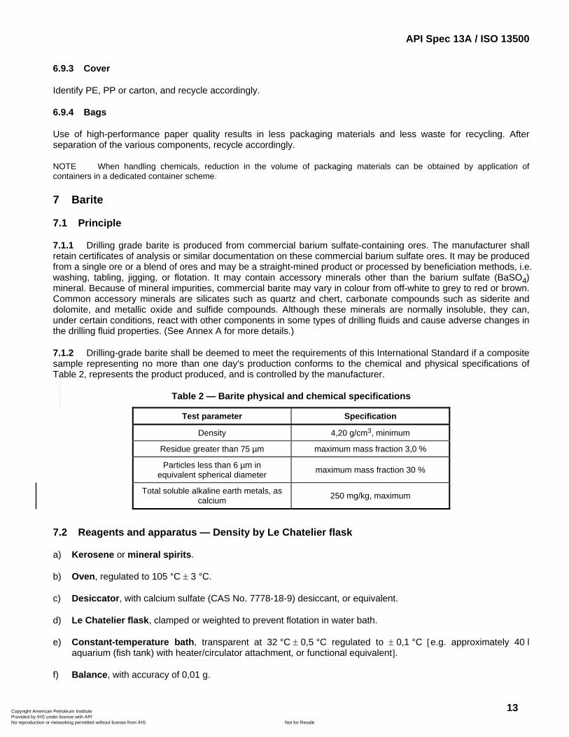
7.1.2 Drilling-grade barite shall be deemed to meet the requirements of this International Standard if a composite sample representing no more than one day's production conforms to the chemical and physical specifications of Table 2, represents the product produced, and is controlled by the manufacturer.
Table 2 — Barite physical and chemical specifications
Test parameter Specification
Density 4,20 g/cm3, minimum
Residue greater than 75 µm maximum mass fraction 3,0 %
Particles less than 6 µm in equivalent spherical diameter maximum mass fraction 30 %
Total soluble alkaline earth metals, as calcium 250 mg/kg, maximum
7.2 Reagents and apparatus — Density by Le Chatelier flask
a) Kerosene or mineral spirits.
b) Oven, regulated to 105 °C ± 3 °C.
c) Desiccator, with calcium sulfate (CAS No. 7778-18-9) desiccant, or equivalent.
d) Le Chatelier flask, clamped or weighted to prevent flotation in water bath.
e) Constant-temperature bath, transparent at 32 °C ± 0,5 °C regulated to ± 0,1 °C [e.g. approximately 40 l aquarium (fish tank) with heater/circulator attachment, or functional equivalent].
f) Balance, with accuracy of 0,01 g.
Copyright American Petroleum Institute Provided by IHS under license with API
Not for ResaleNo reproduction or networking permitted without license from IHS
--`,,```,,,,````-`-`,,`,,`,`,,`---
API Spec 13A / ISO 13500
14
g) Pipette, volumetric, of capacity 10 cm3.
h) Magnifying glass.
i) Dowel, wooden, approximately 8 mm in diameter and 30 cm in length, or a functional equivalent.
j) Tissue paper, absorbent.
NOTE Laboratory grade tissues are non-absorbent and thus unsuitable for use in this test procedure.
k) Weighing dish, low-form, with spout, of approximately 100 cm3 capacity, or a functional equivalent.
l) Brush, small, fine-bristle.
7.3 Procedure — Density by Le Chatelier flask
7.3.1 If required, equilibrate approximately 100 g dried barite to room temperature in the desiccator.
7.3.2 Fill a clean Le Chatelier flask to approximately 22 mm below the zero mark with kerosene.
7.3.3 Place the flask upright in the constant-temperature bath. The level of water in the bath shall be higher than the 24 cm3 graduation of the flask, but below the stopper level. Assure flask is stabilized by use of clamps or weights.
7.3.4 Allow the flask and contents to equilibrate for a minimum of 1 h. Using the magnifying glass with care to keep eyes at meniscus level, read the volume at the lowest portion of the curved interface, and record the initial volume to the nearest 0,05 cm3 (doubtful digit) without removing the flask from the constant-temperature bath. Record as V1.
If the kerosene level is above or below the – 0,2 cm3 to + 1,2 cm3 volume range after equilibrating, use the 10 cm3 pipette to add or remove kerosene in order for it to come within this range. Allow the flask to equilibrate at least 1 h and record initial volume as in 7.3.4.
7.3.5 Remove the Le Chatelier flask from the bath, wipe dry, and remove the stopper. Roll several lengths of tissue paper diagonally along the length of the dowel, and use this assembly as a swab to dry the inside neck of the flask. Do not allow the swab to come into contact with the kerosene in the flask.
7.3.6 Weigh 80 g ± 0,05 g dried barite into the weighing dish and carefully transfer to the Le Chatelier flask. Take care to avoid splashing of the kerosene or plugging of the flask with barite at the bulb. This is a slow process, requiring repeated transfers of small amounts of barite. Use a brush to transfer any residual barite into the flask, then replace the stopper. Record mass as m.
7.3.7 If necessary, carefully tap the neck of the flask with the wooden dowel, or agitate carefully side to side, to dislodge any barite clinging to the walls. Do not allow kerosene to come into contact with the ground glass stopper joint of the flask.
7.3.8 Gently roll the flask along a smooth surface at no more than 45° from vertical, or twirl the upright flask at the neck vigorously between the palms of both hands, to remove entrained air from the barite sample. Repeat this procedure until no more bubbles can be seen rising from the barite.
7.3.9 Return the flask to the bath and let stand for at least 0,5 h.
7.3.10 Remove the flask from the bath and repeat 7.3.8 to remove any remaining air from the barite sample.
7.3.11 Immerse the flask in the bath again for at least 1 h.
7.3.12 Record the final volume in the same manner as described in 7.3.4. Record volume as V2.
Copyright American Petroleum Institute Provided by IHS under license with API
Not for ResaleNo reproduction or networking permitted without license from IHS
--`,,```,,,,````-`-`,,`,,`,`,,`---
API Spec 13A / ISO 13500
15
7.4 Calculation — Density by Le Chatelier flask
Calculate the density, ρ, in grams per cubic centimetre, according to Equation (4):
( )2 1
mV V
ρ =−
(4)
where
m is the sample mass, in grams;
V1 is the initial volume, in cubic centimetres;
V2 is the final volume, in cubic centimetres.
Record calculated density.
7.5 Reagents and apparatus — Water-soluble alkaline earths as calcium
a) Aqueous EDTA solution, composed of 3,72 g ± 0,01 g of the disodium salt of ethylenediaminetetraacetic acid dihydrate [disodium salt of (ethylenedinitrilo)tetraacetic acid dihydrate] (CAS No. 6381-92-6) diluted to a final volume of 1 000 cm3 with deionized water in a volumetric flask.
b) Buffer solution, comprising 67,5 g ± 0,01 g ammonium chloride (CAS No. 12125-02-9) and 570 cm3 ± 1 cm3 of 15 mol/l ammonium hydroxide (CAS No. 1336-21-6) solution diluted to a final volume of 1 000 cm3 with deionized water in a volumetric flask.
c) Hardness indicator solution, comprising 1 g ± 0,01 g Calmagite (CAS No. 3147-14-6), or equivalent [1-(1-hydroxy-4-methylphenylazo)-2-naphthol-4-sulfonic acid] diluted to a final volume of 1000 cm3 with deionized water in a volumetric flask.
d) Deionized (or distilled) water.
e) Balance, of capacity exceeding 100 g with an accuracy of 0,01 g.
f) Erlenmeyer flask, of 250 cm3 nominal capacity, equipped with a tight-fitting stopper.
g) Graduated cylinder, of 100 cm3 capacity (TC) with 1 cm3 graduations.
h) Titration vessel, e.g. beaker, of 100 cm3 to 150 cm3 capacity.
i) Serological pipettes or burette with graduations of 0,1 cm3.
j) Volumetric pipettes (TD), of capacity 10 cm3 or equivalent.
k) Filter press, in accordance with ISO 10414-1, or filtration funnel.
l) Filter paper, Whatman 50, or equivalent.
m) Glass container, small.
n) Wrist-action shaker, optional.
o) Volumetric flask, of capacity 1 000 cm3.
p) Stirring rod.
Copyright American Petroleum Institute Provided by IHS under license with API
Not for ResaleNo reproduction or networking permitted without license from IHS
--`,,```,,,,````-`-`,,`,,`,`,,`---
API Spec 13A / ISO 13500
16
7.6 Procedure — Water-soluble alkaline earth metals as calcium
7.6.1 Weigh 100 g ± 0,05 g of barite. Transfer to the Erlenmeyer flask and add 100 cm3 ± 1 cm3 of deionized water. Stopper the flask and shake for at least 5 min during an approximate 1 h interval or by an optional mechanical shaking apparatus for 20 min to 30 min.
7.6.2 After shaking, filter the suspension through the low-pressure filter cell or funnel using two sheets of filter paper and collect filtrate into suitable glass container.
7.6.3 Add 50 cm3 ± 1 cm3 deionized water to the titration vessel. Add about 2 cm3 of hardness buffer and sufficient hardness indicator to achieve a distinct blue colour. Swirl to mix.
A solution with colour other than distinct blue at this point indicates contamination of equipment and/or water. Find and eliminate the source of contamination and rerun the test.
7.6.4 Using the volumetric pipette, measure 10 cm3 of the filtrate into the titrating vessel. Swirl to mix. A blue colour indicates no calcium hardness and the test is complete. A wine-red colour will develop if calcium and/or magnesium are present. Record as V4.
7.6.5 If hardness is present, begin stirring and titrate with EDTA solution to the blue endpoint. The endpoint of the titration is best described as the point at which additional EDTA produces no further red to blue change. The EDTA volume used to produce the blue endpoint will be used in the calculation in 7.7. Record as V3.
If endpoint is unclear or unobtainable, other tests shall be performed. Results and methodology of these tests shall be recorded.
7.7 Calculation — Water-soluble alkaline earths as calcium
Calculate the soluble alkaline earth metals as calcium, m1, in grams per cubic centimetre, according to Equation (5):
31
4400
Vm
V⎛ ⎞
= ⎜ ⎟⎝ ⎠
(5)
where
m1 is the soluble alkaline earth metals as calcium, expressed in milligrams per kilogram;
V3 is the volume EDTA used, expressed in cubic centimetres;
V4 is the volume of filtrate used, expressed in cubic centimetres.
Record calculated value.
7.8 Reagents and materials — Residue of diameter greater than 75 µm
a) Sodium hexametaphosphate (CAS No. 10124-56-8).
b) Oven, regulated to 105 °C ± 3 °C.
c) Desiccator, with calcium sulfate (CAS No. 7778-18-9) desiccant or equivalent.
d) Balance, with an accuracy of 0,01 g.
e) Mixer (e.g. Multimixer® Model 9B with 9B29X impellers or equivalent), having each spindle fitted with a single sine-wave impeller, approximately 25 mm in diameter, mounted flash side up.
Copyright American Petroleum Institute Provided by IHS under license with API
Not for ResaleNo reproduction or networking permitted without license from IHS
--`,,```,,,,````-`-`,,`,,`,`,,`---
API Spec 13A / ISO 13500
17
f) Container, of approximate dimensions 180 mm deep, 97 mm d top, 70 mm d bottom (e.g. Hamilton Beach® mixer cup No. M110-D 3), or equivalent).
g) Sieve, 75 µm, conforming to the requirements of ASTM E161, of approximate dimensions 76 mm diameter and 69 mm from top of frame to wire cloth.
NOTE Supplier's verification that sieve conforms to ASTM E161 is satisfactory evidence of compliance.
h) Spray nozzle with 1/4 TT body (Spraying Systems Co., No. TG 6.5 tip with 1/4 TT body 4), or equivalent), attached to water line with 90° elbow.
i) Water pressure regulator, capable of regulation to 69 kPa ± 7 kPa.
j) Evaporating dish or functional equivalent.
k) Wash bottle.
7.9 Procedure — Residue of diameter greater than 75 µm
7.9.1 If required, equilibrate approximately 60 g of dried barite in a desiccator.
7.9.2 Weigh 50 g ± 0,01 g of dried barite. Add the weighed sample to approximately 350 cm3 of water containing about 0,2 g of sodium hexametaphosphate. Stir on the mixer for 5 min ± 1 min. Record weight as m.
7.9.3 Transfer the sample to the 75 µm sieve. Use wash bottle to remove all material from the container to the sieve. Wash the material on the sieve with water controlled to 69 kPa ± 7 kPa from a spray nozzle for 2 min ± 15 s. While washing, hold the tip of the spray nozzle approximately in the plane of the top of sieve and move the spray of water repeatedly over the sample.
7.9.4 Wash the residue from the sieve into a tared evaporating dish and decant excess clear water.
7.9.5 Dry the residue in the oven to a constant mass. Record residue mass as m2 and total drying time.
7.10 Calculation — Residue of diameter greater than 75 µm
Calculate the mass fraction residue of particles greater than 75 µm, w1, in percent, according to Equation (6):
21 100
mw
m⎛ ⎞
= ⎜ ⎟⎝ ⎠
(6)
where
m is the sample mass, expressed in grams;
m2 is the residue mass, expressed in grams.
Record calculated value.
3) Hamilton Beach® mixer cup No. M110-D is an example of a suitable product available commercially. This information is given for the convenience of users of this International Standard and does not constitute an endorsement by ISO of this product.
4) Spraying Systems Co., No. TG 6.5 tip with 1/4 TT body is an example of a suitable product available commercially. This information is given for the convenience of users of this International Standard and does not constitute an endorsement by ISO of this product.
Copyright American Petroleum Institute Provided by IHS under license with API
Not for ResaleNo reproduction or networking permitted without license from IHS
--`,,```,,,,````-`-`,,`,,`,`,,`---
API Spec 13A / ISO 13500
18
7.11 Reagents and apparatus — Particles less than 6 µm in equivalent spherical diameter by sedimentation method
a) Dispersant solution, comprising 40 g ± 0,1 g sodium hexametaphosphate and 3,60 g ± 0,1 g anhydrous sodium carbonate (CAS No. 497-19-8) per 1 000 cm3 of solution. The sodium carbonate is used to adjust the pH of the solution to approximately 9,0.
b) Oven, regulated to 105 °C ± 3 °C.
c) Desiccator, with calcium sulfate (CAS No. 7778-18-9) desiccant or equivalent.
d) Balance, with an accuracy of 0,01 g.
e) Mixer (e.g. Multimixer Model 9B with 9B29X impellers or equivalent), having each spindle fitted with a single sine-wave impeller approximately 25 mm in diameter mounted flash side up.
f) Container, of approximate dimensions 180 mm deep, 97 mm d top, 70 mm d bottom (e.g. Hamilton Beach mixer cup No. M110-D, or equivalent).
g) Sedimentation cylinder, glass, approximately 457 mm in height and 63 mm in diameter, marked for a volume of 1 000 cm3 (ASTM D422).
h) Rubber stopper, Number 13.
i) Water bath or constant-temperature room, capable of maintaining a convenient constant temperature at 24 °C ± 5 °C.
j) Thermometer, including the range 16 °C ± 0,5 °C to 32 °C ± 0,5 °C.
k) Hydrometer, ASTM 151H, graduated to read specific gravity of suspension.
l) Timer, mechanical or electrical, with an accuracy of 0,1 min over the test period.
7.12 Procedure — Particles less than 6 µm in equivalent spherical diameter by sedimentation method
7.12.1 Weigh 80 g ± 0,1 g of dry barite and place in container. Record mass as m.
7.12.2 Add 125 cm3 ± 2 cm3 (127 g ± 2 g) of dispersant solution [from 7.11 a)]. Dilute to approximately 400 cm3 with deionized water. Rinse all adhering particles from spatula into suspension.
7.12.3 Stir 5 min ± 0,5 min on mixer.
7.12.4 Transfer the suspension to the sedimentation cylinder. Rinse container with deionized water to assure that all sample particles are transferred to the sedimentation cylinder.
7.12.5 Add deionized water to the 1 000 cm3 mark. Mix the contents thoroughly by constantly changing the cylinder from the upright to the inverted position and back for 60 s ± 5 s while holding a No. 13 rubber stopper in the top of the cylinder.
This is a critical step. Suspension shall be homogeneous at start of sedimentation. This is difficult to obtain because of the high density of barite.
7.12.6 Set the cylinder into the water bath (or on counter-top of constant-temperature room) and simultaneously start the timer. Hang the thermometer in the suspension.
Copyright American Petroleum Institute Provided by IHS under license with API
Not for ResaleNo reproduction or networking permitted without license from IHS
--`,,```,,,,````-`-`,,`,,`,`,,`---
API Spec 13A / ISO 13500
19
7.12.7 Take hydrometer readings at intervals of 10 min ± 0,1 min, 20 min ± 0,1 min, 30 min ± 0,1 min, and 40 min ± 0,1 min (or until the first point below the 6 µm value is reached). To take a hydrometer reading, carefully and slowly lower the hydrometer to approximately the 1,020 reading before releasing. After hydrometer stabilizes, read the top of the meniscus at the prescribed time. Carefully and slowly remove hydrometer, rinse with deionized water, and dry after each reading. The hydrometer shall be removed immediately after each reading to eliminate particle build-up on the shoulders which causes erroneous results. All hydrometer readings shall be done with a minimum of fluid disturbance to preserve suspension-settling equilibrium.
7.12.8 Record time, t, in minutes, the temperature, θ, in degrees Celsius or degrees Fahrenheit, and the hydrometer reading, R3, on data sheet.
Temperature may be measured in either degrees Celsius or degrees Fahrenheit, as long as all measurements and calculations are consistent in units, including hydrometer calibration.
7.12.9 For each time interval, determine water viscosity, η, and effective hydrometer depth, L, from Tables 3 and 4. Record on data sheet.
7.13 Calculation — Particles less than 6 µm in equivalent spherical diameter by sedimentation method
7.13.1 From hydrometer calibration (5.2.5.2) enter hydrometer correction slope, Mc, and hydrometer correction intercept, Bc, into data sheet.
7.13.2 Calculate sample constant, Ks, as given in Equation (7) (or determine from Table 5) and enter into data sheet:
( )s 1001
Km
ρρ
=−
(7)
where
ρ is the sample density, in grams per cubic centimetre;
m is the sample mass, in grams.
7.13.3 Calculate and enter onto data sheet the equivalent spherical diameter, De, in micrometres, for each time interval as given in Equation (8):
( )e 17,51
LDt
ηρ
=−
(8)
where
η is the viscosity of water, in millipascal seconds;
ρ is the density of sample, in grams per cubic centimetre;
t is the time, in minutes;
L is the effective depth, centimetres.
Copyright American Petroleum Institute Provided by IHS under license with API
Not for ResaleNo reproduction or networking permitted without license from IHS
--`,,```,,,,````-`-`,,`,,`,`,,`---
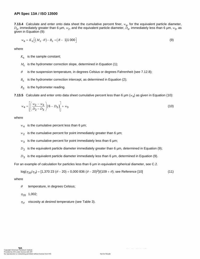
API Spec 13A / ISO 13500
20
⎤⎦
7.13.4 Calculate and enter onto data sheet the cumulative percent finer, wa, for the equivalent particle diameter, De, immediately greater than 6 µm, w2, and the equivalent particle diameter, De, immediately less than 6 µm, w3, as given in Equation (9):
( ) ( )a s c c 1 1 000w K M B Rθ⎡= ⋅ − + −⎣ (9)
where
Ks is the sample constant;
Mc is the hydrometer correction slope, determined in Equation (1);
θ is the suspension temperature, in degrees Celsius or degrees Fahrenheit (see 7.12.8);
Bc is the hydrometer correction intercept, as determined in Equation (2);
R3 is the hydrometer reading.
7.13.5 Calculate and enter onto data sheet cumulative percent less than 6 µm (w4) as given in Equation (10):
( )2 34
2 3
w ww
D D⎡ ⎤⎛ ⎞−
= −⎢⎜ ⎟−⎢ ⎥⎝ ⎠⎣ ⎦
6 3 3D w+⎥ (10)
where
w4 is the cumulative percent less than 6 µm;
w2 is the cumulative percent for point immediately greater than 6 µm;
w3 is the cumulative percent for point immediately less than 6 µm;
D2 is the equivalent particle diameter immediately greater than 6 µm, determined in Equation (9);
D3 is the equivalent particle diameter immediately less than 6 µm, determined in Equation (9).
For an example of calculation for particles less than 6 µm in equivalent spherical diameter, see C.2.
log(η20/ηθ) = [1,370 23 (θ − 20) + 0,000 836 (θ − 20)2]/(109 + θ); see Reference [10] (11)
where
θ temperature, in degrees Celsius;
η20 1,002;
ηθ viscosity at desired temperature (see Table 3).
Copyright American Petroleum Institute Provided by IHS under license with API
Not for ResaleNo reproduction or networking permitted without license from IHS
--`,,```,,,,````-`-`,,`,,`,`,,`---
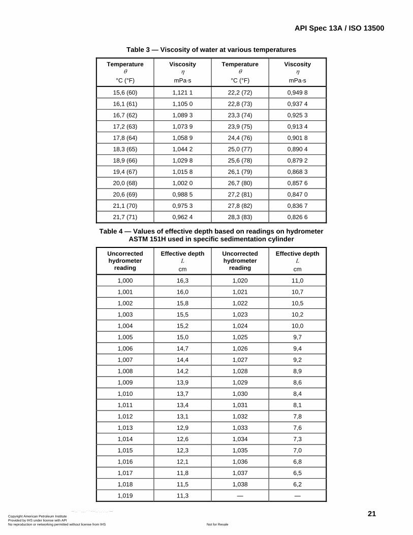
API Spec 13A / ISO 13500
21
Table 3 — Viscosity of water at various temperatures
Temperature θ
°C (°F)
Viscosity η
mPa·s
Temperature θ
°C (°F)
Viscosity η
mPa·s
15,6 (60) 1,121 1 22,2 (72) 0,949 8
16,1 (61) 1,105 0 22,8 (73) 0,937 4
16,7 (62) 1,089 3 23,3 (74) 0,925 3
17,2 (63) 1,073 9 23,9 (75) 0,913 4
17,8 (64) 1,058 9 24,4 (76) 0,901 8
18,3 (65) 1,044 2 25,0 (77) 0,890 4
18,9 (66) 1,029 8 25,6 (78) 0,879 2
19,4 (67) 1,015 8 26,1 (79) 0,868 3
20,0 (68) 1,002 0 26,7 (80) 0,857 6
20,6 (69) 0,988 5 27,2 (81) 0,847 0
21,1 (70) 0,975 3 27,8 (82) 0,836 7
21,7 (71) 0,962 4 28,3 (83) 0,826 6
Table 4 — Values of effective depth based on readings on hydrometer ASTM 151H used in specific sedimentation cylinder
Uncorrected hydrometer
reading
Effective depth L
cm
Uncorrected hydrometer
reading
Effective depth L
cm
1,000 16,3 1,020 11,0
1,001 16,0 1,021 10,7
1,002 15,8 1,022 10,5
1,003 15,5 1,023 10,2
1,004 15,2 1,024 10,0
1,005 15,0 1,025 9,7
1,006 14,7 1,026 9,4
1,007 14,4 1,027 9,2
1,008 14,2 1,028 8,9
1,009 13,9 1,029 8,6
1,010 13,7 1,030 8,4
1,011 13,4 1,031 8,1
1,012 13,1 1,032 7,8
1,013 12,9 1,033 7,6
1,014 12,6 1,034 7,3
1,015 12,3 1,035 7,0
1,016 12,1 1,036 6,8
1,017 11,8 1,037 6,5
1,018 11,5 1,038 6,2
1,019 11,3 — —
Copyright American Petroleum Institute Provided by IHS under license with API
Not for ResaleNo reproduction or networking permitted without license from IHS
--`,,```,,,,````-`-`,,`,,`,`,,`---
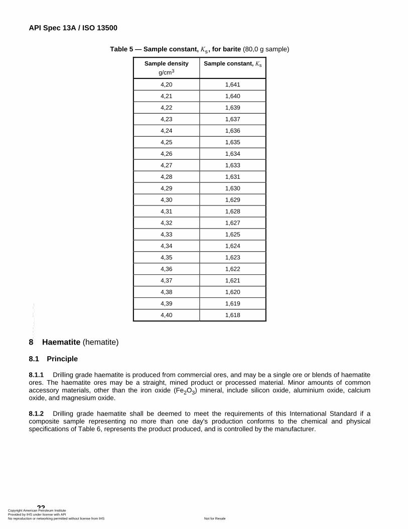
API Spec 13A / ISO 13500
22
Table 5 — Sample constant, Ks , for barite (80,0 g sample)
Sample density g/cm3
Sample constant, Ks
4,20 1,641
4,21 1,640
4,22 1,639
4,23 1,637
4,24 1,636
4,25 1,635
4,26 1,634
4,27 1,633
4,28 1,631
4,29 1,630
4,30 1,629
4,31 1,628
4,32 1,627
4,33 1,625
4,34 1,624
4,35 1,623
4,36 1,622
4,37 1,621
4,38 1,620
4,39 1,619
4,40 1,618
8 Haematite (hematite)
8.1 Principle
8.1.1 Drilling grade haematite is produced from commercial ores, and may be a single ore or blends of haematite ores. The haematite ores may be a straight, mined product or processed material. Minor amounts of common accessory materials, other than the iron oxide (Fe2O3) mineral, include silicon oxide, aluminium oxide, calcium oxide, and magnesium oxide.
8.1.2 Drilling grade haematite shall be deemed to meet the requirements of this International Standard if a composite sample representing no more than one day's production conforms to the chemical and physical specifications of Table 6, represents the product produced, and is controlled by the manufacturer.
Copyright American Petroleum Institute Provided by IHS under license with API
Not for ResaleNo reproduction or networking permitted without license from IHS
--`,,```,,,,````-`-`,,`,,`,`,,`---
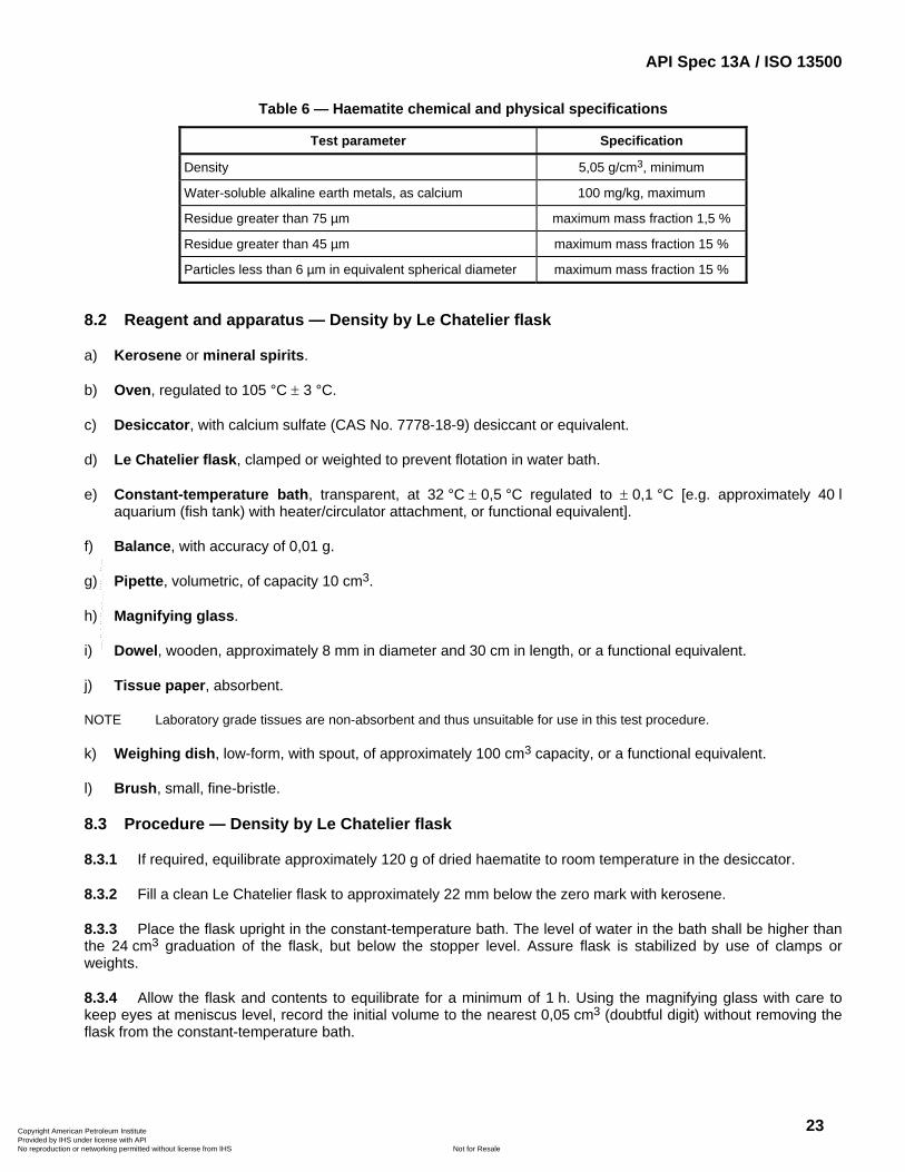
API Spec 13A / ISO 13500
23
Table 6 — Haematite chemical and physical specifications
Test parameter Specification
Density 5,05 g/cm3, minimum
Water-soluble alkaline earth metals, as calcium 100 mg/kg, maximum
Residue greater than 75 µm maximum mass fraction 1,5 %
Residue greater than 45 µm maximum mass fraction 15 %
Particles less than 6 µm in equivalent spherical diameter maximum mass fraction 15 %
8.2 Reagent and apparatus — Density by Le Chatelier flask
a) Kerosene or mineral spirits.
b) Oven, regulated to 105 °C ± 3 °C.
c) Desiccator, with calcium sulfate (CAS No. 7778-18-9) desiccant or equivalent.
d) Le Chatelier flask, clamped or weighted to prevent flotation in water bath.
e) Constant-temperature bath, transparent, at 32 °C ± 0,5 °C regulated to ± 0,1 °C [e.g. approximately 40 l aquarium (fish tank) with heater/circulator attachment, or functional equivalent].
f) Balance, with accuracy of 0,01 g.
g) Pipette, volumetric, of capacity 10 cm3.
h) Magnifying glass.
i) Dowel, wooden, approximately 8 mm in diameter and 30 cm in length, or a functional equivalent.
j) Tissue paper, absorbent.
NOTE Laboratory grade tissues are non-absorbent and thus unsuitable for use in this test procedure.
k) Weighing dish, low-form, with spout, of approximately 100 cm3 capacity, or a functional equivalent.
l) Brush, small, fine-bristle.
8.3 Procedure — Density by Le Chatelier flask
8.3.1 If required, equilibrate approximately 120 g of dried haematite to room temperature in the desiccator.
8.3.2 Fill a clean Le Chatelier flask to approximately 22 mm below the zero mark with kerosene.
8.3.3 Place the flask upright in the constant-temperature bath. The level of water in the bath shall be higher than the 24 cm3 graduation of the flask, but below the stopper level. Assure flask is stabilized by use of clamps or weights.
8.3.4 Allow the flask and contents to equilibrate for a minimum of 1 h. Using the magnifying glass with care to keep eyes at meniscus level, record the initial volume to the nearest 0,05 cm3 (doubtful digit) without removing the flask from the constant-temperature bath.
Copyright American Petroleum Institute Provided by IHS under license with API
Not for ResaleNo reproduction or networking permitted without license from IHS
--`,,```,,,,````-`-`,,`,,`,`,,`---
API Spec 13A / ISO 13500
24
If kerosene level is above or below the − 0,2 cm3 to + 1,2 cm3 volume range after equilibrating, use the 10 cm3 pipette to add or remove kerosene in order for it to come within this range. Allow the flask to equilibrate at least 1 h and record initial volume as in 8.3.4.
8.3.5 Remove the Le Chatelier flask from the bath, wipe dry, and remove the stopper. Roll several lengths of tissue paper diagonally along the length of the dowel, and use this assembly as a swab to dry the inside neck of the flask. Do not allow the swab to come into contact with the kerosene in the flask.
8.3.6 Weigh 100 g ± 0,01 g dried haematite into the weighing dish and carefully transfer to the Le Chatelier flask. Take care to avoid splashing of the kerosene or plugging of the flask with haematite at the bulb. This is a slow process, requiring repeated transfers of small amounts of haematite. Use a brush to transfer any residual haematite into the flask, then replace the stopper.
8.3.7 If necessary, carefully tap the neck of the flask with the wooden dowel, or agitate carefully side to side to dislodge any haematite clinging to the walls. Do not allow kerosene to come into contact with the ground glass stopper joint of the flask.
8.3.8 Gently roll the flask along a smooth surface at no more than 45° from vertical, or twirl the upright flask at the neck vigorously between the palms of both hands to remove entrained air from the haematite sample. Repeat this procedure until no more bubbles can be seen rising from the haematite.
8.3.9 Return the flask to the bath and let stand for at least 0,5 h.
8.3.10 Remove the flask from the bath and repeat 8.3.8 to remove any remaining air from the haematite sample.
8.3.11 Immerse the flask in the bath again for at least 1 h.
8.3.12 Record the final volume in the same manner as described in 8.3.4.
8.4 Calculation — Density by Le Chatelier flask
Calculate the density, ρ, in grams per cubic centimetre, according to Equation (4):
( )2 1
mV V
ρ =−
(4)
where
m is the sample mass, in grams;
V1 is the initial volume, in cubic centimetres;
V2 is the final volume, in cubic centimetres.
Record calculated density.
8.5 Reagents and apparatus — Water-soluble alkaline earth metals as calcium
a) Aqueous EDTA solution, comprising 3,72 g ± 0,01 g of disodium salt of ethylenediaminetetraacetic acid dihydrate [disodium salt of (ethylenedinitrilo)tetraacetic acid dihydrate] (CAS No. 6381-92-6) diluted to a final volume of 1 000 cm3 with deionized water in a volumetric flask.
b) Buffer solution, comprising 67,5 g ± 0,01 g ammonium chloride (CAS No. 12125-02-9) and 570 cm3 ± 1 cm3 ammonium hydroxide, c(NaOH) = 15 mol/l (CAS No. 1336-21-6) solution diluted to a final volume of 1 000 cm3 with deionized water in a volumetric flask.
Copyright American Petroleum Institute Provided by IHS under license with API
Not for ResaleNo reproduction or networking permitted without license from IHS
--`,,```,,,,````-`-`,,`,,`,`,,`---
API Spec 13A / ISO 13500
25
c) Hardness indicator solution, 1 g ± 0,01 g Calmagite (CAS No. 3147-14-6) or equivalent [1-(1-hydroxy-4-methylphenylazo)-2-naphthol-4-sulfonic acid] diluted to a final volume of 1 000 cm3 with deionized water in a volumetric flask.
d) Deionized (or distilled) water.
e) Balance, of capacity exceeding 100 g with a precision of 0,01 g.
f) Erlenmeyer flask, of 250 cm3 nominal capacity, equipped with a tight-fitting stopper.
g) Graduated cylinder, of 100 cm3 capacity (TC) with 1 cm3 graduations.
h) Titration vessel, e.g. beaker, of 100 cm3 to 150 cm3 capacity.
i) Serological pipettes or burette, with graduations in 0,1 cm3.
j) Volumetric pipettes (TD), 10 cm3 or equivalent.
k) Filter press, as referenced in ISO 10414-1, or filtration funnel.
l) Filter paper: Whatman 50, or equivalent.
m) Glass container, small.
n) Wrist-action shaker, optional.
o) Volumetric flask, of capacity 1 000 cm3.
p) Stirring rod.
8.6 Procedure — Water-soluble alkaline earth metals as calcium
8.6.1 Weigh 100 g ± 0,05 g of haematite. Transfer to the Erlenmeyer flask and add 100 cm3 ± 1 cm3 of deionized water. Stopper the flask and shake for at least 5 min during an approximate 1 h interval or by an optional mechanical shaking apparatus for 20 min to 30 min.
8.6.2 After shaking, filter the suspension through the low-pressure filter cell or funnel using two sheets of filter paper and collect filtrate into suitable glass container.
8.6.3 Add 50 cm3 ± 1 cm3 deionized water to the titration vessel. Add about 2 cm3 of hardness buffer and sufficient hardness indicator to achieve a distinct blue colour. Swirl to mix.
A solution with colour other than distinct blue at this point indicates contamination of equipment and/or water. Find and eliminate the source of contamination and rerun the test.
8.6.4 Using the volumetric pipette, measure 10 cm3 of the filtrate into the titrating vessel. Swirl to mix. A blue colour indicates no calcium hardness and the test is complete. A wine-red colour will develop if calcium and/or magnesium are present.
8.6.5 If hardness is present, begin stirring and titrate with EDTA solution to the blue endpoint. The endpoint of the titration is best described as the point at which additional EDTA produces no further red to blue change. The EDTA volume used to produce the blue endpoint is used in the calculation in 8.7.
If endpoint is unclear or unobtainable, other tests such as atomic adsorption spectroscopy shall be performed. Results and methodology of these tests shall be recorded.
Copyright American Petroleum Institute Provided by IHS under license with API
Not for ResaleNo reproduction or networking permitted without license from IHS
--`,,```,,,,````-`-`,,`,,`,`,,`---
API Spec 13A / ISO 13500
26
8.7 Calculation — Water-soluble alkaline earth metals as calcium
Calculate the soluble alkaline earth metals as calcium, m1, in grams per cubic centimetre, according to Equation (5):
31
4400
Vm
V⎛ ⎞
= ⎜ ⎟⎝ ⎠
(5)
where
V3 is the volume EDTA used, in cubic centimetres;
V4 is the volume of filtrate used, in cubic centimetres.
Record calculated value.
8.8 Reagents and apparatus — Residues greater that 75 µm and 45 µm
a) Sodium hexametaphosphate (CAS No. 10124-56-8).
b) Oven, regulated to 105 °C ± 3 °C.
c) Desiccator, with calcium sulfate (CAS No. 7778-18-9) desiccant or equivalent.
d) Balance, with an accuracy of 0,01 g.
e) Mixer (e.g. Multimixer® Model 9B with 9B29X impellers or equivalent) having each spindle fitted with a single sine-wave impeller, approximately 25 mm in diameter, mounted flash side up.
f) Container, of approximate dimensions 180 mm deep, 97 mm d top, 70 mm d bottom (e.g. Hamilton® Beach mixer cup No. M110-D, or equivalent).
g) Sieve, 75 µm, conforming to the requirements of ASTM E 161-96 of approximate dimensions 76 mm diameter and 69 mm from top of frame to wire cloth.
NOTE Supplier's verification that sieve conforms to ASTM E 161-96 is satisfactory evidence of compliance.
h) Sieve, 45 µm, conforming to the requirements of ASTM E 161-96, of approximate dimensions 76 mm diameter and 69 mm from top of frame to wire cloth.
NOTE Supplier's verification that sieve conforms to ASTM E 161-96 is satisfactory evidence of compliance.
i) Spray nozzle, 1/4 TT body (Spraying Systems Company, No. TG 6.5 tip with 1/4 TT body or equivalent) 5), attached to water line with 90° elbow.
j) Water pressure regulator, capable of regulation to 69 kPa ± 7 kPa.
k) Evaporating dish, or functional equivalent.
l) Wash bottle.
8.9 Procedure — Residues of diameter greater than 75 µm and 45 µm
8.9.1 If required, equilibrate approximately 120 g of dried haematite to room temperature in the desiccator.
5) This item is an example of a suitable product available commercially. This information is given for the convenience of users of this International Standard and does not constitute an endorsement by ISO of this product.
Copyright American Petroleum Institute Provided by IHS under license with API
Not for ResaleNo reproduction or networking permitted without license from IHS
--`,,```,,,,````-`-`,,`,,`,`,,`---
API Spec 13A / ISO 13500
27
8.9.2 Weigh 50 g ± 0,01 g of dried haematite. Add the weighed sample to approximately 350 cm3 of water containing about 0,2 g of sodium hexametaphosphate. Stir on the mixer for 5 min ± 1 min.
8.9.3 Transfer the sample to the 75-µm sieve. Use wash bottle to remove all material from the container to the sieve. Wash the material on the sieve with water controlled to 69 kPa ± 7 kPa from a spray nozzle for 2 min ± 15 s. While washing, hold the tip of the spray nozzle approximately in the plane of the top of sieve and move the spray of water repeatedly over the sample.
8.9.4 Wash the residue from the sieve into a tared evaporating dish and decant excess clear water.
8.9.5 Dry the residue in the oven to constant mass. Record residue mass and total drying time.
8.9.6 Repeat steps 8.9.2 through 8.9.5 using the 45-µm sieve.
8.10 Calculation — Residues of diameter greater than 75 µm and 45 µm
Calculate the mass fraction residue of particles greater than 75 µm, w1, in percent, according to Equation (6) and the mass fraction residue of particles greater than 45 µm, w5, in percent, according to Equation (12):
21 100
mw
m⎛ ⎞
= ⎜ ⎟⎝ ⎠
(6)
where
m is the sample mass, in grams;
m2 is the residue mass, in grams.
Record calculated value.
25 100
mw
m⎛ ⎞
= ⎜ ⎟⎝ ⎠
(12)
where
m is the sample mass, in grams;
m2 is the residue mass, in grams.
Record calculated value.
8.11 Reagents and apparatus — Particles less than 6 µm in equivalent spherical diameter by sedimentation method
a) Dispersant solution, comprising 40 g ± 0,1 g sodium hexametaphosphate and 3,60 g ± 0,1 g anhydrous sodium carbonate (CAS No. 497-19-8) per 1 000 cm3 of solution. The sodium carbonate is used to adjust the pH of the solution to approximately 9,0.
b) Oven, regulated to 105 °C ± 3 °C.
c) Desiccator, with calcium sulfate (CAS No. 7778-18-9) desiccant or equivalent.
d) Balance, with an accuracy of 0,01 g.
e) Mixer (e.g. Multimixer Model 9B with 9B29X impellers or equivalent), having each spindle fitted with a single sine-wave impeller, approximately 25 mm in diameter, mounted flash side up.
Copyright American Petroleum Institute Provided by IHS under license with API
Not for ResaleNo reproduction or networking permitted without license from IHS
--`,,```,,,,````-`-`,,`,,`,`,,`---
API Spec 13A / ISO 13500
28
f) Container, of approximate dimensions 180 mm deep, 97 mm d top, 70 mm d bottom (e.g. Hamilton Beach mixer cup No. M110-D, or equivalent).
g) Sedimentation cylinder, glass, approximately 457 mm in height and 63 mm in diameter, marked for a volume of 1 000 cm3 (ASTM D422).
h) Rubber stopper, size No. 13.
i) Water bath or constant-temperature room, capable of maintaining a convenient constant temperature at 24 °C ± 5 °C.
j) Thermometer, including the range 16 °C ± 0,5 °C to 32 °C ± 0,5 °C.
k) Hydrometer, ASTM 151H, graduated to read specific gravity of suspension.
l) Timer, mechanical or electrical, with an accuracy of 0,1 min over the test interval.
8.12 Procedure — Particles less than 6 µm in equivalent spherical diameter by sedimentation method
8.12.1 Weigh 80 g ± 0,1 g of dry haematite and place in container.
8.12.2 Add 125 cm3 ± 2 cm3 (127 g ± 2 g) of dispersant solution [8.11 a)]. Dilute to approximately 400 cm3 with deionized water. Rinse all adhering particles from spatula into suspension.
8.12.3 Stir 5 min ± 0,5 min on mixer.
8.12.4 Transfer the suspension to the sedimentation cylinder. Rinse mixing container with deionized water to assure that all sample particles are transferred to the sedimentation cylinder.
8.12.5 Add deionized water to the 1 000 cm3 mark. Mix the contents thoroughly by constantly changing the cylinder from the upright to the inverted position and back for 60 s ± 5 s while holding a No. 13 rubber stopper in the top of the cylinder.
This is a critical step. Suspensions shall be homogeneous at start of sedimentation. This is difficult to obtain because of the high density of haematite.
8.12.6 Set the cylinder into the water bath (or counter-top of constant-temperature room) and simultaneously start the timer. Hang the thermometer in the suspension.
8.12.7 Take hydrometer readings at intervals of 10 min ± 0,1 min, 20 min ± 0,1 min, 30 min ± 0,1 min, and 40 min ± 0,1 min (or until the first point below the 6 µm value is reached). To take a hydrometer reading, carefully and slowly lower the hydrometer to approximately the 1,020 reading before releasing. After hydrometer stabilizes, read the top of the meniscus at the prescribed time. Carefully and slowly remove hydrometer, rinse with deionized water and dry after each reading. Remove the hydrometer immediately after each reading to eliminate particle build-up on the shoulders which causes erroneous results. All hydrometer readings shall be done with a minimum of fluid disturbance to preserve suspension-settling equilibrium.
8.12.8 Record time, t, in minutes, the temperature, θ, in degrees Celsius or degrees Fahrenheit and the hydrometer reading, R3, on the data sheet.
Temperature may be measured in either degrees Celsius or degrees Fahrenheit as long as all measurements and calculations are consistent in units, including hydrometer calibration.
8.12.9 For each time interval, determine water viscosity, η, and effective hydrometer depth, L, from Tables 3 and 4. Record on data sheet.
Copyright American Petroleum Institute Provided by IHS under license with API
Not for ResaleNo reproduction or networking permitted without license from IHS
--`,,```,,,,````-`-`,,`,,`,`,,`---
API Spec 13A / ISO 13500
29
8.13 Calculation — Particles less than 6 µm in equivalent spherical diameter by sedimentation method
8.13.1 From hydrometer calibration (5.2.5), enter hydrometer correction slope, Mc , and hydrometer correction intercept, Bc , into data sheet.
8.13.2 Calculate sample constant, Ks , as given in Equation (7) (or determine from Table 7) and enter into data sheet:
( )s 1001
Km
ρρ
=−
(7)
where
ρ is the density of sample, in grams per cubic centimetre;
m is the mass of sample, in grams.
8.13.3 Calculate and enter onto data sheet the equivalent spherical diameter, De, for each time interval as given in Equation (8):
( )e 17,51
LDt
ηρ
=−
(8)
where
η is the viscosity of water, in millipascal·seconds;
ρ is the density of sample, in grams per cubic centimetre;
t is the time, in minutes;
L is the effective depth, in centimetres.
8.13.4 Calculate and enter onto data sheet the cumulative percent finer, wa, for the equivalent particle diameter, De, immediately greater than 6 µm, w2, and the equivalent particle diameter, De, immediately less than 6 µm, w3, as given in Equation (9):
( ) ( )a s c c 1 1000w K M B Rθ⎡= ⋅ − + −⎣ ⎤⎦ (9)
where
Ks is the sample constant;
Mc is the hydrometer correction slope;
θ is the suspension temperature, in degrees Celsius or degrees Fahrenheit (see 8.12.8);
Bc is the hydrometer correction intercept;
R3 is the hydrometer reading.
Copyright American Petroleum Institute Provided by IHS under license with API
Not for ResaleNo reproduction or networking permitted without license from IHS
--`,,```,,,,````-`-`,,`,,`,`,,`---
API Spec 13A / ISO 13500
30
Table 7 — Sample constant, Ks , for haematite (80,0 g sample)
Sample density g/cm3
Sample constant, Ks
5,00 1,562 5
5,01 1,561 7
5,02 1,560 9
5,03 1,560 2
5,04 1,559 4
5,05 1,558 6
5,06 1,557 9
5,07 1,557 1
5,08 1,556 4
5,09 1,555 6
5,10 1,554 9
5,11 1,554 1
5,12 1,553 4
5,13 1,552 7
5,14 1,551 9
5,15 1,551 2
5,16 1,550 5
5,17 1,549 8
5,18 1,549 0
5,19 1,548 3
5,20 1,547 6
5,21 1,546 9
5,22 1,546 2
5,23 1,545 5
5,24 1,544 8
5,25 1,544 1
5,26 1,543 4
5,27 1,542 7
5,28 1,542 1
5,29 1,541 4
5,30 1,540 7
Copyright American Petroleum Institute Provided by IHS under license with API
Not for ResaleNo reproduction or networking permitted without license from IHS
--`,,```,,,,````-`-`,,`,,`,`,,`---
API Spec 13A / ISO 13500
31
8.13.5 Calculate and enter onto data sheet cumulative percent less than 6 µm (w6) as follows:
( )2 36
2 36
w ww
D D⎡ ⎤⎛ ⎞−
= −⎢⎜ ⎟−⎢ ⎥⎝ ⎠⎣ ⎦
3 3D w+⎥ (10)
where
w6 is the cumulative percent less than 6 µm;
w2 is the cumulative percent for point immediately greater than 6 µm;
w3 is the cumulative percent for point immediately less than 6 µm;
D2 is the equivalent particle diameter immediately greater than 6 µm;
D3 is the equivalent particle diameter immediately less than 6 µm.
For an example of calculation for particles less than 6 µm in equivalent spherical diameter, see C.3.
9 Bentonite
9.1 Principle
9.1.1 Drilling grade bentonite is a naturally occurring clay containing the clay mineral smectite. It may also contain accessory minerals, such as quartz, mica, feldspar and calcite.
9.1.2 Drilling grade bentonite shall be deemed to meet the requirements of this International Standard if a composite sample representing no more than one day's production conforms to the physical specifications of Table 8, represents the product produced, and is controlled by the manufacturer.
Table 8 — Bentonite physical specifications
Test parameter Specification
Suspension properties:
Viscometer dial reading at 600 r/min minimum 30
Yield point/plastic viscosity ratio maximum 3
Filtrate volume maximum, 15,0 cm3
Residue of diameter greater than 75 µm maximum mass fraction 4,0 %
9.2 Reagents and apparatus — Suspension properties
a) Thermometer, accurate to ± 0,5 °C over the range specified in the procedure.
b) Balance, with an accuracy of 0,01 g.
c) Mixer (e.g. Multimixer® Model 9B with 9B29X impellers or equivalent), having spindle fitted with a single sine-wave impeller approximately 25 mm in diameter mounted flash side up.
d) Container, of approximate dimensions 180 mm deep, 97 mm d top, 70 mm d bottom (e.g. Hamilton® Beach mixer cup No. M110-D, or equivalent).
e) Spatula.
Copyright American Petroleum Institute Provided by IHS under license with API
Not for ResaleNo reproduction or networking permitted without license from IHS
--`,,```,,,,````-`-`,,`,,`,`,,`---
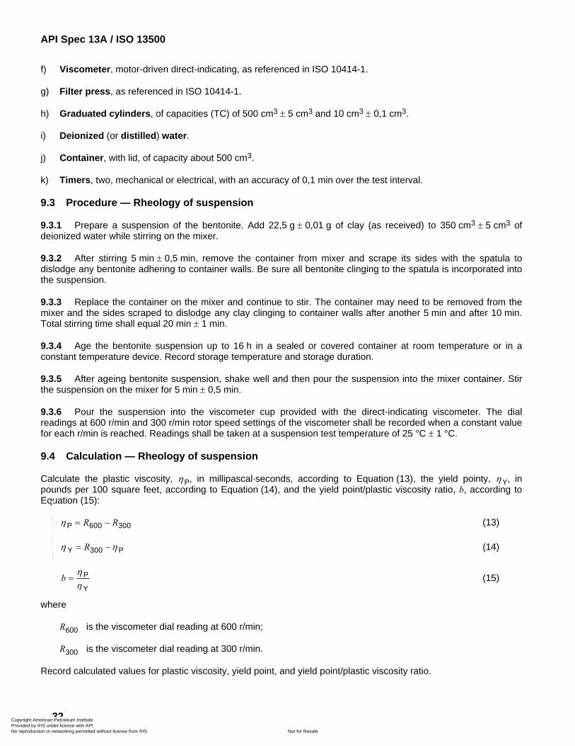
API Spec 13A / ISO 13500
32
f) Viscometer, motor-driven direct-indicating, as referenced in ISO 10414-1.
g) Filter press, as referenced in ISO 10414-1.
h) Graduated cylinders, of capacities (TC) of 500 cm3 ± 5 cm3 and 10 cm3 ± 0,1 cm3.
i) Deionized (or distilled) water.
j) Container, with lid, of capacity about 500 cm3.
k) Timers, two, mechanical or electrical, with an accuracy of 0,1 min over the test interval.
9.3 Procedure — Rheology of suspension
9.3.1 Prepare a suspension of the bentonite. Add 22,5 g ± 0,01 g of clay (as received) to 350 cm3 ± 5 cm3 of deionized water while stirring on the mixer.
9.3.2 After stirring 5 min ± 0,5 min, remove the container from mixer and scrape its sides with the spatula to dislodge any bentonite adhering to container walls. Be sure all bentonite clinging to the spatula is incorporated into the suspension.
9.3.3 Replace the container on the mixer and continue to stir. The container may need to be removed from the mixer and the sides scraped to dislodge any clay clinging to container walls after another 5 min and after 10 min. Total stirring time shall equal 20 min ± 1 min.
9.3.4 Age the bentonite suspension up to 16 h in a sealed or covered container at room temperature or in a constant temperature device. Record storage temperature and storage duration.
9.3.5 After ageing bentonite suspension, shake well and then pour the suspension into the mixer container. Stir the suspension on the mixer for 5 min ± 0,5 min.
9.3.6 Pour the suspension into the viscometer cup provided with the direct-indicating viscometer. The dial readings at 600 r/min and 300 r/min rotor speed settings of the viscometer shall be recorded when a constant value for each r/min is reached. Readings shall be taken at a suspension test temperature of 25 °C ± 1 °C.
9.4 Calculation — Rheology of suspension
Calculate the plastic viscosity, ηP, in millipascal·seconds, according to Equation (13), the yield pointy, ηY, in pounds per 100 square feet, according to Equation (14), and the yield point/plastic viscosity ratio, b, according to Equation (15):
P 600 300R Rη = − (13)
Y 300 PRη η= − (14)
P
Yb
ηη
= (15)
where
R600 is the viscometer dial reading at 600 r/min;
R300 is the viscometer dial reading at 300 r/min.
Record calculated values for plastic viscosity, yield point, and yield point/plastic viscosity ratio.
Copyright American Petroleum Institute Provided by IHS under license with API
Not for ResaleNo reproduction or networking permitted without license from IHS
--`,,```,,,,````-`-`,,`,,`,`,,`---
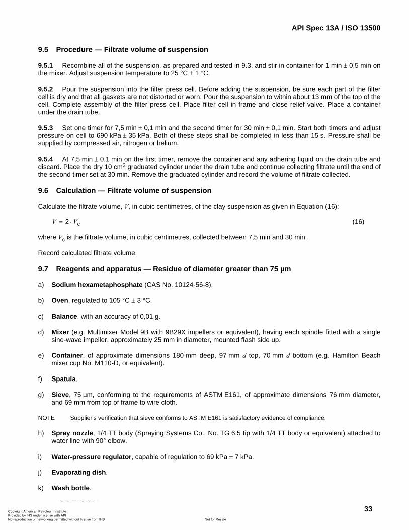
API Spec 13A / ISO 13500
33
9.5 Procedure — Filtrate volume of suspension
9.5.1 Recombine all of the suspension, as prepared and tested in 9.3, and stir in container for 1 min ± 0,5 min on the mixer. Adjust suspension temperature to 25 °C ± 1 °C.
9.5.2 Pour the suspension into the filter press cell. Before adding the suspension, be sure each part of the filter cell is dry and that all gaskets are not distorted or worn. Pour the suspension to within about 13 mm of the top of the cell. Complete assembly of the filter press cell. Place filter cell in frame and close relief valve. Place a container under the drain tube.
9.5.3 Set one timer for 7,5 min ± 0,1 min and the second timer for 30 min ± 0,1 min. Start both timers and adjust pressure on cell to 690 kPa ± 35 kPa. Both of these steps shall be completed in less than 15 s. Pressure shall be supplied by compressed air, nitrogen or helium.
9.5.4 At 7,5 min ± 0,1 min on the first timer, remove the container and any adhering liquid on the drain tube and discard. Place the dry 10 cm3 graduated cylinder under the drain tube and continue collecting filtrate until the end of the second timer set at 30 min. Remove the graduated cylinder and record the volume of filtrate collected.
9.6 Calculation — Filtrate volume of suspension
Calculate the filtrate volume, V, in cubic centimetres, of the clay suspension as given in Equation (16):
c2V V= ⋅ (16)
where Vc is the filtrate volume, in cubic centimetres, collected between 7,5 min and 30 min.
Record calculated filtrate volume.
9.7 Reagents and apparatus — Residue of diameter greater than 75 µm
a) Sodium hexametaphosphate (CAS No. 10124-56-8).
b) Oven, regulated to 105 °C ± 3 °C.
c) Balance, with an accuracy of 0,01 g.
d) Mixer (e.g. Multimixer Model 9B with 9B29X impellers or equivalent), having each spindle fitted with a single sine-wave impeller, approximately 25 mm in diameter, mounted flash side up.
e) Container, of approximate dimensions 180 mm deep, 97 mm d top, 70 mm d bottom (e.g. Hamilton Beach mixer cup No. M110-D, or equivalent).
f) Spatula.
g) Sieve, 75 µm, conforming to the requirements of ASTM E161, of approximate dimensions 76 mm diameter, and 69 mm from top of frame to wire cloth.
NOTE Supplier's verification that sieve conforms to ASTM E161 is satisfactory evidence of compliance.
h) Spray nozzle, 1/4 TT body (Spraying Systems Co., No. TG 6.5 tip with 1/4 TT body or equivalent) attached to water line with 90° elbow.
i) Water-pressure regulator, capable of regulation to 69 kPa ± 7 kPa.
j) Evaporating dish.
k) Wash bottle.
Copyright American Petroleum Institute Provided by IHS under license with API
Not for ResaleNo reproduction or networking permitted without license from IHS
--`,,```,,,,````-`-`,,`,,`,`,,`---
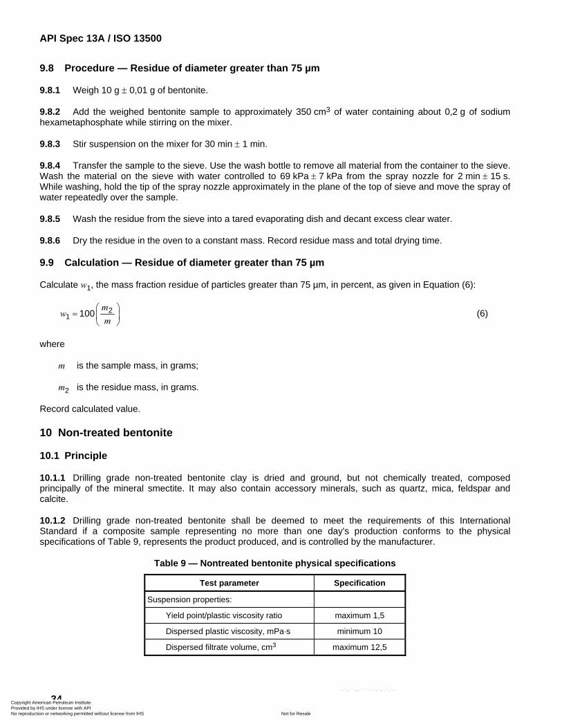
API Spec 13A / ISO 13500
34
9.8 Procedure — Residue of diameter greater than 75 µm
9.8.1 Weigh 10 g ± 0,01 g of bentonite.
9.8.2 Add the weighed bentonite sample to approximately 350 cm3 of water containing about 0,2 g of sodium hexametaphosphate while stirring on the mixer.
9.8.3 Stir suspension on the mixer for 30 min ± 1 min.
9.8.4 Transfer the sample to the sieve. Use the wash bottle to remove all material from the container to the sieve. Wash the material on the sieve with water controlled to 69 kPa ± 7 kPa from the spray nozzle for 2 min ± 15 s. While washing, hold the tip of the spray nozzle approximately in the plane of the top of sieve and move the spray of water repeatedly over the sample.
9.8.5 Wash the residue from the sieve into a tared evaporating dish and decant excess clear water.
9.8.6 Dry the residue in the oven to a constant mass. Record residue mass and total drying time.
9.9 Calculation — Residue of diameter greater than 75 µm
Calculate w1, the mass fraction residue of particles greater than 75 µm, in percent, as given in Equation (6):
21 100
mw
m⎛ ⎞
= ⎜ ⎟⎝ ⎠
(6)
where
m is the sample mass, in grams;
m2 is the residue mass, in grams.
Record calculated value.
10 Non-treated bentonite
10.1 Principle
10.1.1 Drilling grade non-treated bentonite clay is dried and ground, but not chemically treated, composed principally of the mineral smectite. It may also contain accessory minerals, such as quartz, mica, feldspar and calcite.
10.1.2 Drilling grade non-treated bentonite shall be deemed to meet the requirements of this International Standard if a composite sample representing no more than one day's production conforms to the physical specifications of Table 9, represents the product produced, and is controlled by the manufacturer.
Table 9 — Nontreated bentonite physical specifications
Test parameter Specification
Suspension properties:
Yield point/plastic viscosity ratio maximum 1,5
Dispersed plastic viscosity, mPa·s minimum 10
Dispersed filtrate volume, cm3 maximum 12,5
Copyright American Petroleum Institute Provided by IHS under license with API
Not for ResaleNo reproduction or networking permitted without license from IHS
--`,,```,,,,````-`-`,,`,,`,`,,`---
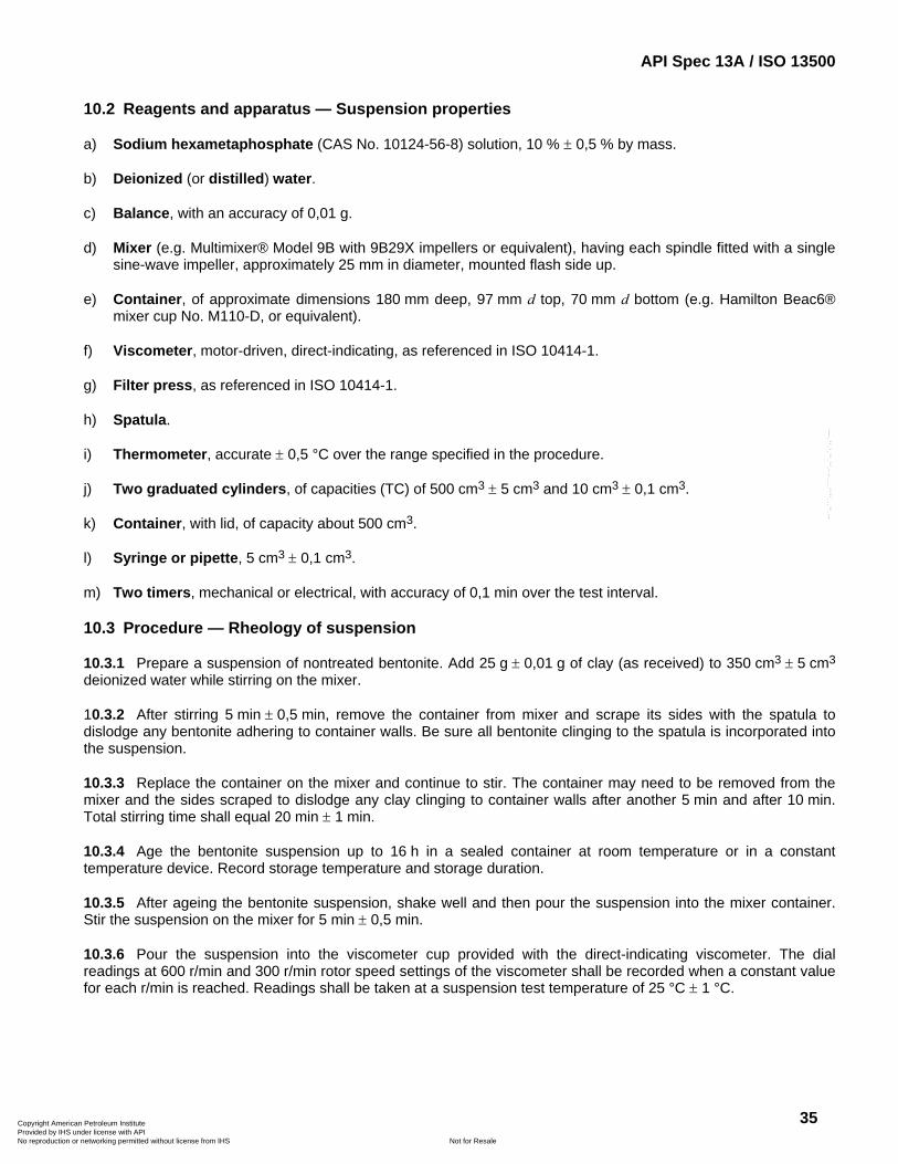
API Spec 13A / ISO 13500
35
10.2 Reagents and apparatus — Suspension properties
a) Sodium hexametaphosphate (CAS No. 10124-56-8) solution, 10 % ± 0,5 % by mass.
b) Deionized (or distilled) water.
c) Balance, with an accuracy of 0,01 g.
d) Mixer (e.g. Multimixer® Model 9B with 9B29X impellers or equivalent), having each spindle fitted with a single sine-wave impeller, approximately 25 mm in diameter, mounted flash side up.
e) Container, of approximate dimensions 180 mm deep, 97 mm d top, 70 mm d bottom (e.g. Hamilton Beac6® mixer cup No. M110-D, or equivalent).
f) Viscometer, motor-driven, direct-indicating, as referenced in ISO 10414-1.
g) Filter press, as referenced in ISO 10414-1.
h) Spatula.
i) Thermometer, accurate ± 0,5 °C over the range specified in the procedure.
j) Two graduated cylinders, of capacities (TC) of 500 cm3 ± 5 cm3 and 10 cm3 ± 0,1 cm3.
k) Container, with lid, of capacity about 500 cm3.
l) Syringe or pipette, 5 cm3 ± 0,1 cm3.
m) Two timers, mechanical or electrical, with accuracy of 0,1 min over the test interval.
10.3 Procedure — Rheology of suspension
10.3.1 Prepare a suspension of nontreated bentonite. Add 25 g ± 0,01 g of clay (as received) to 350 cm3 ± 5 cm3 deionized water while stirring on the mixer.
10.3.2 After stirring 5 min ± 0,5 min, remove the container from mixer and scrape its sides with the spatula to dislodge any bentonite adhering to container walls. Be sure all bentonite clinging to the spatula is incorporated into the suspension.
10.3.3 Replace the container on the mixer and continue to stir. The container may need to be removed from the mixer and the sides scraped to dislodge any clay clinging to container walls after another 5 min and after 10 min. Total stirring time shall equal 20 min ± 1 min.
10.3.4 Age the bentonite suspension up to 16 h in a sealed container at room temperature or in a constant temperature device. Record storage temperature and storage duration.
10.3.5 After ageing the bentonite suspension, shake well and then pour the suspension into the mixer container. Stir the suspension on the mixer for 5 min ± 0,5 min.
10.3.6 Pour the suspension into the viscometer cup provided with the direct-indicating viscometer. The dial readings at 600 r/min and 300 r/min rotor speed settings of the viscometer shall be recorded when a constant value for each r/min is reached. Readings shall be taken at a suspension test temperature of 25 °C ± 1 °C.
Copyright American Petroleum Institute Provided by IHS under license with API
Not for ResaleNo reproduction or networking permitted without license from IHS
--`,,```,,,,````-`-`,,`,,`,`,,`---
API Spec 13A / ISO 13500
36
10.4 Calculation — Rheology of suspension
Calculate the plastic viscosity, ηP, in millipascal·seconds, according to Equation (13), the yield pointy, ηY, in pounds per 100 square feet, according to Equation (14), and the yield point/plastic viscosity ratio, b, according to Equation (15):
P 600 300R Rη = − (13)
Y 300 PRη η= − (14)
P
Yb
ηη
= (15)
where
R600 is the viscometer dial reading at 600 r/min;
R300 is the viscometer dial reading at 300 r/min.
Record calculated values for plastic viscosity, yield point, and yield point/plastic viscosity ratio.
10.5 Procedure — Dispersed plastic viscosity of suspension
10.5.1 Recombine all of the bentonite suspension, as prepared and tested in 10.3, and stir in container for 1 min ± 0,5 min on the mixer.
10.5.2 Add 5 cm3 ± 0,1 cm3 of a 10 % solution of sodium hexametaphosphate to the suspension and stir for 3 min ± 0,5 min on the mixer.
10.5.3 Pour the suspension into the viscometer cup provided with the direct-indicating viscometer. The dial readings at 600 r/min and 300 r/min rotor speed settings of the viscometer shall be recorded when a constant value for each r/min is reached. Readings shall be taken at a suspension test temperature of 25 °C ± 1 °C.
10.5.4 Calculate and record the dispersed plastic viscosity as per Equation (13).
10.6 Procedure — Dispersed filtrate volume of suspension
10.6.1 Recombine all of the suspension as prepared and tested in 10.5 and stir in container for 1 min ± 0,5 min on the mixer. Adjust suspension temperature to 25 °C ± 1 °C.
10.6.2 Pour the suspension into the filter press cell. Before adding the suspension, be sure each part of the filter cell is dry and that all gaskets are not distorted or worn. Pour the suspension to within about 13 mm of the top of the cell. Complete assembly of the filter press cell. Place filter cell in frame and close relief valve. Place a container under the drain tube.
10.6.3 Set one timer for 7,5 min ± 0,1 min and the second timer for 30 min ± 0,1 min. Start both timers and adjust pressure on cell to 690 kPa ± 35 kPa. Both of these steps shall be completed in less than 15 s. Pressure shall be supplied by compressed air, nitrogen, or helium.
10.6.4 At 7,5 min ± 0,1 min on the first timer, remove the container and any adhering liquid on the drain tube and discard. Place the dry 10 cm3 graduated cylinder under the drain tube and continue collecting filtrate to the end of the second timer set at 30 min. Remove the graduated cylinder and record the volume of filtrate collected.
10.7 Calculation — Dispersed filtrate volume of suspension
Calculate the filtrate volume, V, in cubic centimetres, of the clay suspension as given in Equation (16):
Copyright American Petroleum Institute Provided by IHS under license with API
Not for ResaleNo reproduction or networking permitted without license from IHS
--`,,```,,,,````-`-`,,`,,`,`,,`---
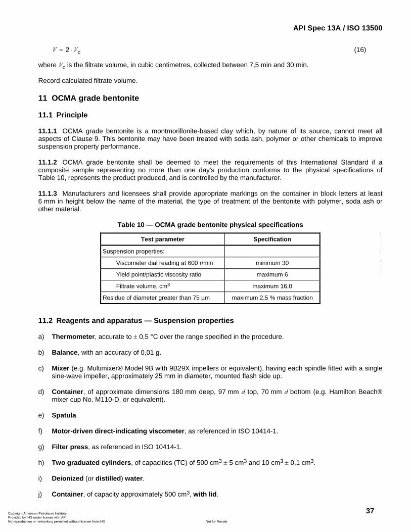
API Spec 13A / ISO 13500
37
c2V V= ⋅ (16)
where Vc is the filtrate volume, in cubic centimetres, collected between 7,5 min and 30 min.
Record calculated filtrate volume.
11 OCMA grade bentonite
11.1 Principle
11.1.1 OCMA grade bentonite is a montmorillonite-based clay which, by nature of its source, cannot meet all aspects of Clause 9. This bentonite may have been treated with soda ash, polymer or other chemicals to improve suspension property performance.
11.1.2 OCMA grade bentonite shall be deemed to meet the requirements of this International Standard if a composite sample representing no more than one day's production conforms to the physical specifications of Table 10, represents the product produced, and is controlled by the manufacturer.
11.1.3 Manufacturers and licensees shall provide appropriate markings on the container in block letters at least 6 mm in height below the name of the material, the type of treatment of the bentonite with polymer, soda ash or other material.
Table 10 — OCMA grade bentonite physical specifications
Test parameter Specification
Suspension properties:
Viscometer dial reading at 600 r/min minimum 30
Yield point/plastic viscosity ratio maximum 6
Filtrate volume, cm3 maximum 16,0
Residue of diameter greater than 75 µm maximum 2,5 % mass fraction
11.2 Reagents and apparatus — Suspension properties
a) Thermometer, accurate to ± 0,5 °C over the range specified in the procedure.
b) Balance, with an accuracy of 0,01 g.
c) Mixer (e.g. Multimixer® Model 9B with 9B29X impellers or equivalent), having each spindle fitted with a single sine-wave impeller, approximately 25 mm in diameter, mounted flash side up.
d) Container, of approximate dimensions 180 mm deep, 97 mm d top, 70 mm d bottom (e.g. Hamilton Beach® mixer cup No. M110-D, or equivalent).
e) Spatula.
f) Motor-driven direct-indicating viscometer, as referenced in ISO 10414-1.
g) Filter press, as referenced in ISO 10414-1.
h) Two graduated cylinders, of capacities (TC) of 500 cm3 ± 5 cm3 and 10 cm3 ± 0,1 cm3.
i) Deionized (or distilled) water.
j) Container, of capacity approximately 500 cm3, with lid.
Copyright American Petroleum Institute Provided by IHS under license with API
Not for ResaleNo reproduction or networking permitted without license from IHS
--`,,```,,,,````-`-`,,`,,`,`,,`---
API Spec 13A / ISO 13500
38
k) Two timers, mechanical or electrical, with accuracy of 0,1 min over the test interval.
11.3 Procedure — Rheology of suspension
11.3.1 Prepare a suspension of OCMA grade bentonite. Add 22,5 g ± 0,01 g clay (as received) to 350 cm3 ± 5 cm3 of deionized water while stirring on the mixer.
11.3.2 After stirring 5 min ± 0,5 min, remove container from mixer and scrape its sides with the spatula to dislodge any bentonite adhering to container walls. Be sure all bentonite clinging to the spatula is incorporated into the suspension.
11.3.3 Replace the container on the mixer and continue to stir. The container may need to be removed from the mixer and the sides scraped to dislodge any clay clinging to container walls after another 5 min and after 10 min. Total stirring time shall equal 20 min ± 1 min.
11.3.4 Age the bentonite suspension up to 16 h in a sealed or covered container at room temperature or in a constant temperature device. Record storage temperature and storage duration.
11.3.5 After ageing bentonite suspension, shake well and then pour the suspension into the mixer container. Stir the suspension on the mixer for 5 min ± 0,5 min.
11.3.6 Pour the suspension into the viscometer cup provided with the direct indicating viscometer. The dial readings at 600 r/min and 300 r/min rotor speed settings of the viscometer shall be recorded when a constant value for each r/min is reached. Readings shall be taken at a suspension test temperature of 25 °C ± 1 °C.
11.4 Calculation — Rheology of suspension
Calculate the plastic viscosity, ηP, in millipascal·seconds, according to Equation (13), the yield pointy, ηY, in pounds per 100 square feet, according to Equation (14), and the yield point/plastic viscosity ratio, b, according to Equation (15):
P 600 300R Rη = − (13)
Y 300 PRη η= − (14)
P
Yb
ηη
= (15)
where
R600 is the viscometer dial reading at 600 r/min;
R300 is the viscometer dial reading at 300 r/min.
Record calculated values for plastic viscosity, yield point, and yield point/plastic viscosity ratio.
11.5 Procedure — Filtrate volume of suspension
11.5.1 Recombine all of the suspension, as prepared and tested in 11.3, and stir in container for 1 min ± 0,5 min on the mixer. Adjust suspension temperature to 25 °C ± 1 °C.
11.5.2 Pour the suspension into the filter press cell. Before adding the suspension, be sure each part of the filter cell is dry and that all gaskets are not distorted or worn. Pour the suspension to within about 13 mm of the top of the cell. Complete assembly of the filter press cell. Place filter cell in frame and close relief valve. Place a container under the drain tube.
Copyright American Petroleum Institute Provided by IHS under license with API
Not for ResaleNo reproduction or networking permitted without license from IHS
--`,,```,,,,````-`-`,,`,,`,`,,`---
API Spec 13A / ISO 13500
39
11.5.3 Set one timer for 7,5 min ± 0,1 min and the second timer for 30 min ± 0,1 min. Start both timers and adjust pressure on cell to 690 kPa ± 35 kPa. Both of these steps shall be completed in less than 15 s. Pressure shall be supplied by compressed air, nitrogen or helium.
11.5.4 At 7,5 min ± 0,1 min on the first timer, remove the container and any adhering liquid on the drain tube and discard. Place the dry 10 cm3 graduated cylinder under the drain tube and continue collecting filtrate to the end of the second timer set at 30 min. Remove the graduated cylinder and record the volume of filtrate collected.
11.6 Calculation — Filtrate volume of suspension
Calculate the filtrate volume, V, in cubic centimetres, of the clay suspension as given in Equation (16):
c2V V= ⋅ (16)
where Vc is the filtrate volume, in cubic centimetres, collected between 7,5 min and 30 min.
Record calculated filtrate volume.
11.7 Reagents and apparatus — Residue of diameter greater than 75 µm
a) Sodium hexametaphosphate (CAS No. 10124-56-8).
b) Oven, regulated to 105 °C ± 3 °C.
c) Balance, with an accuracy of 0,01 g.
d) Mixer (e.g. Multimixer Model 9B with 9B29X impellers or equivalent), having each spindle fitted with a single sine-wave impeller, approximately 25 mm in diameter, mounted flash side up.
e) Container, of approximate dimensions 180 mm deep, 97 mm d top, 70 mm d bottom (e.g. Hamilton Beach mixer cup No. M110-D, or equivalent).
f) Spatula.
g) Sieve, 75 µm conforming to the requirements of ASTM E161, of approximate dimensions 76 mm diameter and 69 mm from top of frame to wire cloth.
NOTE Supplier's verification that sieve conforms to ASTM E161 is satisfactory evidence of compliance.
h) Spray nozzle, 1/4 TT body (Spraying Systems Co., No. TG 6.5 tip with 1/4 TT body or equivalent), attached to water line with 90° elbow.
i) Water-pressure regulator, capable of regulation to 69 kPa ± 7 kPa.
j) Evaporating dish.
k) Wash bottle.
11.8 Procedure — Residue of diameter greater than 75 µm
11.8.1 Weigh 10 g ± 0,01 g of bentonite.
11.8.2 Add the weighed sample to approximately 350 cm3 of water, containing about 0,2 g of sodium hexametaphosphate while stirring on the mixer.
11.8.3 Stir suspension on the mixer for 30 min ± 1 min.
11.8.4 Transfer the sample to sieve. Use the wash bottle to remove all material from the container to the sieve. Wash the material on the sieve with water controlled to 69 kPa ± 7 kPa from a spray nozzle for 2 min ± 15 s. While
Copyright American Petroleum Institute Provided by IHS under license with API
Not for ResaleNo reproduction or networking permitted without license from IHS
--`,,```,,,,````-`-`,,`,,`,`,,`---
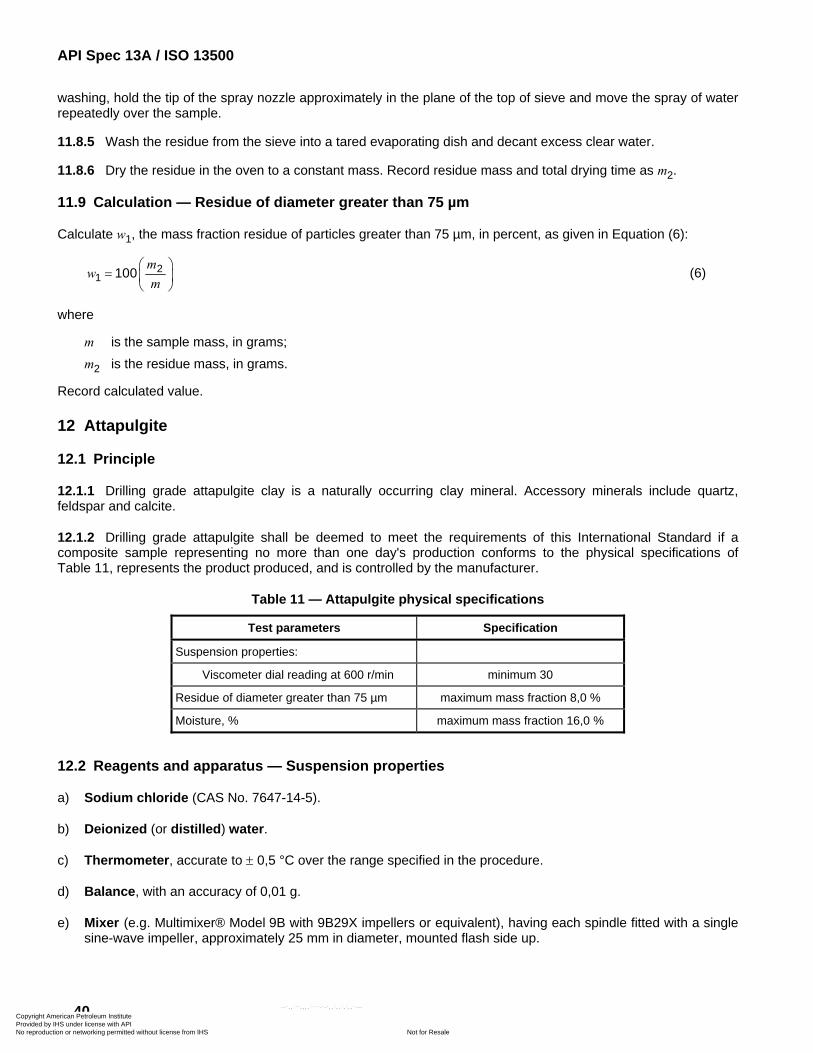
API Spec 13A / ISO 13500
40
washing, hold the tip of the spray nozzle approximately in the plane of the top of sieve and move the spray of water repeatedly over the sample.
11.8.5 Wash the residue from the sieve into a tared evaporating dish and decant excess clear water.
11.8.6 Dry the residue in the oven to a constant mass. Record residue mass and total drying time as m2.
11.9 Calculation — Residue of diameter greater than 75 µm
Calculate w1, the mass fraction residue of particles greater than 75 µm, in percent, as given in Equation (6):
21 100
mw
m⎛ ⎞
= ⎜ ⎟⎝ ⎠
(6)
where
m is the sample mass, in grams; m2 is the residue mass, in grams.
Record calculated value.
12 Attapulgite
12.1 Principle
12.1.1 Drilling grade attapulgite clay is a naturally occurring clay mineral. Accessory minerals include quartz, feldspar and calcite.
12.1.2 Drilling grade attapulgite shall be deemed to meet the requirements of this International Standard if a composite sample representing no more than one day's production conforms to the physical specifications of Table 11, represents the product produced, and is controlled by the manufacturer.
Table 11 — Attapulgite physical specifications
Test parameters Specification
Suspension properties:
Viscometer dial reading at 600 r/min minimum 30
Residue of diameter greater than 75 µm maximum mass fraction 8,0 %
Moisture, % maximum mass fraction 16,0 %
12.2 Reagents and apparatus — Suspension properties
a) Sodium chloride (CAS No. 7647-14-5).
b) Deionized (or distilled) water.
c) Thermometer, accurate to ± 0,5 °C over the range specified in the procedure.
d) Balance, with an accuracy of 0,01 g.
e) Mixer (e.g. Multimixer® Model 9B with 9B29X impellers or equivalent), having each spindle fitted with a single sine-wave impeller, approximately 25 mm in diameter, mounted flash side up.
Copyright American Petroleum Institute Provided by IHS under license with API
Not for ResaleNo reproduction or networking permitted without license from IHS
--`,,```,,,,````-`-`,,`,,`,`,,`---
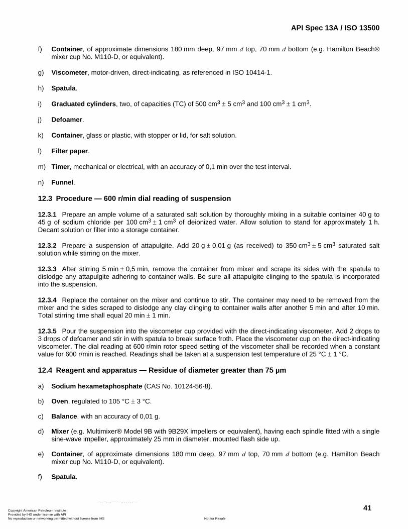
API Spec 13A / ISO 13500
41
f) Container, of approximate dimensions 180 mm deep, 97 mm d top, 70 mm d bottom (e.g. Hamilton Beach® mixer cup No. M110-D, or equivalent).
g) Viscometer, motor-driven, direct-indicating, as referenced in ISO 10414-1.
h) Spatula.
i) Graduated cylinders, two, of capacities (TC) of 500 cm3 ± 5 cm3 and 100 cm3 ± 1 cm3.
j) Defoamer.
k) Container, glass or plastic, with stopper or lid, for salt solution.
l) Filter paper.
m) Timer, mechanical or electrical, with an accuracy of 0,1 min over the test interval.
n) Funnel.
12.3 Procedure — 600 r/min dial reading of suspension
12.3.1 Prepare an ample volume of a saturated salt solution by thoroughly mixing in a suitable container 40 g to 45 g of sodium chloride per 100 cm3 ± 1 cm3 of deionized water. Allow solution to stand for approximately 1 h. Decant solution or filter into a storage container.
12.3.2 Prepare a suspension of attapulgite. Add 20 g ± 0,01 g (as received) to 350 cm3 ± 5 cm3 saturated salt solution while stirring on the mixer.
12.3.3 After stirring 5 min ± 0,5 min, remove the container from mixer and scrape its sides with the spatula to dislodge any attapulgite adhering to container walls. Be sure all attapulgite clinging to the spatula is incorporated into the suspension.
12.3.4 Replace the container on the mixer and continue to stir. The container may need to be removed from the mixer and the sides scraped to dislodge any clay clinging to container walls after another 5 min and after 10 min. Total stirring time shall equal 20 min ± 1 min.
12.3.5 Pour the suspension into the viscometer cup provided with the direct-indicating viscometer. Add 2 drops to 3 drops of defoamer and stir in with spatula to break surface froth. Place the viscometer cup on the direct-indicating viscometer. The dial reading at 600 r/min rotor speed setting of the viscometer shall be recorded when a constant value for 600 r/min is reached. Readings shall be taken at a suspension test temperature of 25 °C ± 1 °C.
12.4 Reagent and apparatus — Residue of diameter greater than 75 µm
a) Sodium hexametaphosphate (CAS No. 10124-56-8).
b) Oven, regulated to 105 °C ± 3 °C.
c) Balance, with an accuracy of 0,01 g.
d) Mixer (e.g. Multimixer® Model 9B with 9B29X impellers or equivalent), having each spindle fitted with a single sine-wave impeller, approximately 25 mm in diameter, mounted flash side up.
e) Container, of approximate dimensions 180 mm deep, 97 mm d top, 70 mm d bottom (e.g. Hamilton Beach mixer cup No. M110-D, or equivalent).
f) Spatula.
Copyright American Petroleum Institute Provided by IHS under license with API
Not for ResaleNo reproduction or networking permitted without license from IHS
--`,,```,,,,````-`-`,,`,,`,`,,`---
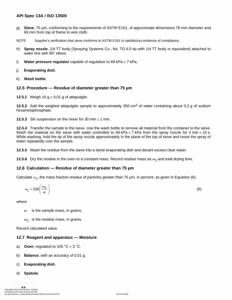
API Spec 13A / ISO 13500
42
g) Sieve, 75 µm, conforming to the requirements of ASTM E161, of approximate dimensions 76 mm diameter and 69 mm from top of frame to wire cloth.
NOTE Supplier's verification that sieve conforms to ASTM E161 is satisfactory evidence of compliance.
h) Spray nozzle, 1/4 TT body (Spraying Systems Co., No. TG 6.5 tip with 1/4 TT body or equivalent) attached to water line with 90° elbow.
i) Water pressure regulator capable of regulation to 69 kPa ± 7 kPa.
j) Evaporating dish.
k) Wash bottle.
12.5 Procedure — Residue of diameter greater than 75 µm
12.5.1 Weigh 10 g ± 0,01 g of attapulgite.
12.5.2 Add the weighed attapulgite sample to approximately 350 cm3 of water containing about 0,2 g of sodium hexametaphosphate.
12.5.3 Stir suspension on the mixer for 30 min ± 1 min.
12.5.4 Transfer the sample to the sieve. Use the wash bottle to remove all material from the container to the sieve. Wash the material on the sieve with water controlled to 69 kPa ± 7 kPa from the spray nozzle for 2 min ± 15 s. While washing, hold the tip of the spray nozzle approximately in the plane of the top of sieve and move the spray of water repeatedly over the sample.
12.5.5 Wash the residue from the sieve into a tared evaporating dish and decant excess clear water.
12.5.6 Dry the residue in the oven to a constant mass. Record residue mass as m2 and total drying time.
12.6 Calculation — Residue of diameter greater than 75 µm
Calculate w1, the mass fraction residue of particles greater than 75 µm, in percent, as given in Equation (6):
21 100
mw
m⎛ ⎞
= ⎜ ⎟⎝ ⎠
(6)
where
m is the sample mass, in grams;
m2 is the residue mass, in grams.
Record calculated value.
12.7 Reagent and apparatus — Moisture
a) Oven, regulated to 105 °C ± 3 °C.
b) Balance, with an accuracy of 0,01 g.
c) Evaporating dish.
d) Spatula.
Copyright American Petroleum Institute Provided by IHS under license with API
Not for ResaleNo reproduction or networking permitted without license from IHS
--`,,```,,,,````-`-`,,`,,`,`,,`---
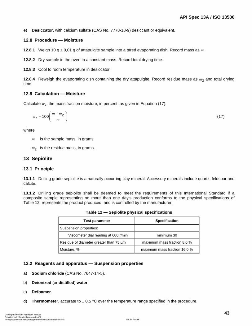
API Spec 13A / ISO 13500
43
e) Desiccator, with calcium sulfate (CAS No. 7778-18-9) desiccant or equivalent.
12.8 Procedure — Moisture
12.8.1 Weigh 10 g ± 0,01 g of attapulgite sample into a tared evaporating dish. Record mass as m.
12.8.2 Dry sample in the oven to a constant mass. Record total drying time.
12.8.3 Cool to room temperature in desiccator.
12.8.4 Reweigh the evaporating dish containing the dry attapulgite. Record residue mass as m2 and total drying time.
12.9 Calculation — Moisture
Calculate w7, the mass fraction moisture, in percent, as given in Equation (17):
27 100
m mw
m−⎛ ⎞
= ⎜ ⎟⎝ ⎠
(17)
where
m is the sample mass, in grams;
m2 is the residue mass, in grams.
13 Sepiolite
13.1 Principle
13.1.1 Drilling grade sepiolite is a naturally occurring clay mineral. Accessory minerals include quartz, feldspar and calcite.
13.1.2 Drilling grade sepiolite shall be deemed to meet the requirements of this International Standard if a composite sample representing no more than one day's production conforms to the physical specifications of Table 12, represents the product produced, and is controlled by the manufacturer.
Table 12 — Sepiolite physical specifications
Test parameter Specification
Suspension properties:
Viscometer dial reading at 600 r/min minimum 30
Residue of diameter greater than 75 µm maximum mass fraction 8,0 %
Moisture, % maximum mass fraction 16,0 %
13.2 Reagents and apparatus — Suspension properties
a) Sodium chloride (CAS No. 7647-14-5).
b) Deionized (or distilled) water.
c) Defoamer.
d) Thermometer, accurate to ± 0,5 °C over the temperature range specified in the procedure.
Copyright American Petroleum Institute Provided by IHS under license with API
Not for ResaleNo reproduction or networking permitted without license from IHS
--`,,```,,,,````-`-`,,`,,`,`,,`---
API Spec 13A / ISO 13500
44
e) Balance, with an accuracy of 0,01 g.
f) Mixer (e.g. Multimixer® Model 9B with 9B29X impellers or equivalent), having each spindle fitted with a single sine-wave impeller, approximately 25 mm in diameter, mounted flash side up.
g) Container, of approximate dimensions 180 mm deep, 97 mm d top, 70 mm d bottom (e.g. Hamilton Beach® mixer cup No. M110-D, or equivalent).
h) Viscometer, motor-driven, direct-indicating, as referenced in ISO 10414-1.
i) Spatula.
j) Graduated cylinders, two, of capacities (TC) of 500 cm3 ± 5 cm3 and 100 cm3 ± 1 cm3.
k) Container, with glass or plastic stopper or lid, for salt solution.
l) Filter paper.
m) Timer, mechanical or electrical, with accuracy of ± 0,1 min over test interval.
n) Funnel.
13.3 Procedure — 600 r/min dial reading of suspension
13.3.1 Prepare an ample volume of a saturated salt solution by thoroughly mixing in a suitable container 40 g to 45 g of sodium chloride per 100 cm3 ± 1 cm3 of deionized water. Allow solution to stand for approximately 1 h. Decant solution or filter it into a storage container.
13.3.2 Prepare a suspension of sepiolite. Add 20 g ± 0,01 g (as received) to 350 cm3 ± 5 cm3 of saturated salt solution while stirring on the mixer.
13.3.3 After stirring 5 min ± 0,5 min, remove the container from mixer and scrape its sides with the spatula to remove or dislodge any sepiolite adhering to container walls. Be sure all sepiolite clinging to the spatula is incorporated into the suspension.
13.3.4 Replace the container on the mixer and continue to stir. The container may need to be removed from the mixer and the sides scraped to dislodge any clay clinging to container walls after another 5 min and after 10 min. Total stirring time shall equal 20 min ± 1 min.
13.3.5 Pour the suspension into the viscometer cup provided with the direct-indicating viscometer. Add 2 drops to 3 drops of defoamer and stir in with spatula to break surface froth. Place the viscometer cup on direct-indicating viscometer. The dial reading at 600 r/min rotor speed setting of the viscometer shall be recorded when a constant value for 600 r/min is reached. Readings shall be taken at a suspension test temperature of 25 °C ± 1 °C.
13.4 Reagents and apparatus — Residue of diameter greater than 75 µm
a) Sodium hexametaphosphate (CAS No. 10124-56-8).
b) Oven, regulated to 105 °C ± 3 °C.
c) Balance, with an accuracy of 0,01 g.
d) Mixer (e.g. Multimixer Model 9B with 9B29X impellers or equivalent), having each spindle fitted with a single sine-wave impeller, approximately 25 mm in diameter, mounted flash side up.
e) Container, of approximate dimensions 180 mm deep, 97 mm d top, 70 mm d bottom (e.g. Hamilton Beach mixer cup No. M110-D, or equivalent).
Copyright American Petroleum Institute Provided by IHS under license with API
Not for ResaleNo reproduction or networking permitted without license from IHS
--`,,```,,,,````-`-`,,`,,`,`,,`---
API Spec 13A / ISO 13500
45
f) Spatula.
g) Sieve, 75 µm, conforming to the requirements of ASTM E161, of approximate dimensions 76 mm diameter and 69 mm from top of frame to wire cloth.
NOTE Supplier's verification that sieve conforms to ASTM E161 is satisfactory evidence of compliance.
h) Spray nozzle, 1/4 TT body (Spraying Systems Company, No. TG 6.5 tip with 1/4 TT body or equivalent), attached to water line with 90 degree elbow.
i) Water-pressure regulator, capable of regulation to 69 kPa ± 7 kPa.
j) Evaporating dish.
k) Wash bottle.
13.5 Procedure — Residue of diameter greater than 75 µm
13.5.1 Weigh 10 g ± 0,01 g of sepiolite.
13.5.2 Add the weighed sepiolite sample to approximately 350 cm3 of water containing about 0,2 g of sodium hexametaphosphate.
13.5.3 Stir suspension on the mixer for 30 min ± 1 min.
13.5.4 Transfer the sample to the sieve. Use the wash bottle to remove all material from the container to the sieve. Wash the material on the sieve with water controlled to 69 kPa ± 7 kPa from the spray nozzle for 2 min ± 15 s. While washing, hold the tip of the spray nozzle approximately in the plane of the top of sieve and move the spray of water repeatedly over the sample.
13.5.5 Wash the residue from the sieve into a tared evaporating dish and decant excess clear water.
13.5.6 Dry the residue in the oven to a constant mass. Record residue mass as m2 and total drying time.
13.6 Calculation — Residue of diameter greater than 75 µm
Calculate w1, the mass fraction residue of particles greater than 75 µm, in percent, as given in Equation (6):
21 100
mw
m⎛ ⎞
= ⎜ ⎟⎝ ⎠
(6)
where
m is the sample mass, in grams;
m2 is the residue mass, in grams.
Record calculated value.
13.7 Reagents and apparatus — Moisture
a) Oven, regulated to 105 °C ± 3 °C.
b) Balance, with an accuracy of 0,01 g.
c) Evaporating dish.
Copyright American Petroleum Institute Provided by IHS under license with API
Not for ResaleNo reproduction or networking permitted without license from IHS
--`,,```,,,,````-`-`,,`,,`,`,,`---
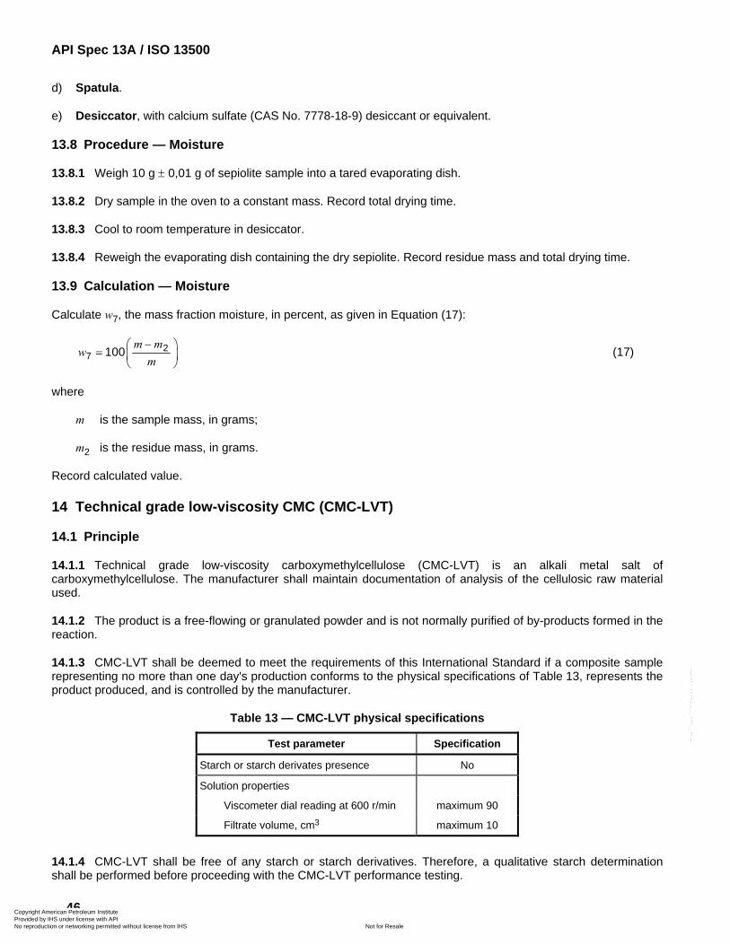
API Spec 13A / ISO 13500
46
d) Spatula.
e) Desiccator, with calcium sulfate (CAS No. 7778-18-9) desiccant or equivalent.
13.8 Procedure — Moisture
13.8.1 Weigh 10 g ± 0,01 g of sepiolite sample into a tared evaporating dish.
13.8.2 Dry sample in the oven to a constant mass. Record total drying time.
13.8.3 Cool to room temperature in desiccator.
13.8.4 Reweigh the evaporating dish containing the dry sepiolite. Record residue mass and total drying time.
13.9 Calculation — Moisture
Calculate w7, the mass fraction moisture, in percent, as given in Equation (17):
27 100
m mw
m−⎛ ⎞
= ⎜ ⎟⎝ ⎠
(17)
where
m is the sample mass, in grams;
m2 is the residue mass, in grams.
Record calculated value.
14 Technical grade low-viscosity CMC (CMC-LVT)
14.1 Principle
14.1.1 Technical grade low-viscosity carboxymethylcellulose (CMC-LVT) is an alkali metal salt of carboxymethylcellulose. The manufacturer shall maintain documentation of analysis of the cellulosic raw material used.
14.1.2 The product is a free-flowing or granulated powder and is not normally purified of by-products formed in the reaction.
14.1.3 CMC-LVT shall be deemed to meet the requirements of this International Standard if a composite sample representing no more than one day's production conforms to the physical specifications of Table 13, represents the product produced, and is controlled by the manufacturer.
Table 13 — CMC-LVT physical specifications
Test parameter Specification
Starch or starch derivates presence No
Solution properties
Viscometer dial reading at 600 r/min maximum 90
Filtrate volume, cm3 maximum 10
14.1.4 CMC-LVT shall be free of any starch or starch derivatives. Therefore, a qualitative starch determination shall be performed before proceeding with the CMC-LVT performance testing.
Copyright American Petroleum Institute Provided by IHS under license with API
Not for ResaleNo reproduction or networking permitted without license from IHS
--`,,```,,,,````-`-`,,`,,`,`,,`---
API Spec 13A / ISO 13500
47
14.2 Reagents and apparatus — Determination of starch and starch derivatives
a) Distilled (or deionized) water.
b) Iodine solution (CAS No. 7553-56-2), 0,1 N.
c) Potassium iodide (CAS No. 7681-11-01).
d) Sodium hydroxide (NaOH) (CAS No. 1310-73-2), dilute solution, 0,1 % to 0,5 %.
e) Mixer (e.g. Multimixer® model 9B with 9B29X impellers or equivalent), having each spindle fitted with a single-wave impeller, approximately 25 mm in diameter, mounted flash side up.
f) Container, approximate dimensions 180 mm deep, 97 mm d top, 70 mm d bottom (e.g. Hamilton Beach® mixer cup No. M110-D, or equivalent).
g) Spatula.
h) Balance, with accuracy of 0,01 g.
i) Volumetric flask, 100 cm3.
j) Pasteur pipette or drop bottle, plastic.
k) Timer, mechanical or electric, with accuracy of 0,1 min over the test interval.
l) pH meter.
m) Test tubes, four.
14.3 Procedure — Determination of starch and starch derivatives
14.3.1 This test identifies the presence of starch and starch derivatives in water-soluble polymers, like CMC-LVT, supplied in powder or granular form.
14.3.2 An iodine/iodide solution is mixed with a solution of the polymer to be analysed. In the presence of amylose (linear fraction of starch), a coloured complex is formed.
14.3.3 Prepare the iodine/iodide solution using a 100 cm3 ± 0,1 cm3 volumetric flask. Add 10 cm3 ± 0,1 cm3 of 0,1 N iodine solution. Add 0,60 g ± 0,01 g of potassium iodide (KI) and dissolve by gently swirling the volumetric flask. Bring to the 100 cm3 mark with deionized water and mix thoroughly. Record the day of preparation.
Store the iodine/iodide solution prepared in a sealed container, in a dark, cool and dry place. It may be used up to three months. After the date of expiry, discard the solution and prepare again.
14.3.4 Prepare a 5 % solution of the water-soluble polymer under examination (CMC-LVT) by adding 380 g ± 0,1 g of deionized water to the container. Add 20 g ± 0,1 g of the water-soluble polymer under examination at a uniform rate over a time interval of 60 s to 120 s while stirring on the mixer. The water-soluble polymer shall be added into the vortex away from the impeller shaft to minimize dusting.
14.3.5 After stirring 5 min ± 0,1 min, remove the container from the mixer and scrape the sides of the mixing container with the spatula to remove or dislodge any polymer adhering to the container walls. Be sure that all of the polymer clinging to the spatula is incorporated into the solution.
14.3.6 Measure the pH. If the pH-value is less than 10, raise the pH to 10 by adding drop-wise dilution NaOH solution.
Copyright American Petroleum Institute Provided by IHS under license with API
Not for ResaleNo reproduction or networking permitted without license from IHS
--`,,```,,,,````-`-`,,`,,`,`,,`---
API Spec 13A / ISO 13500
48
14.3.7 Replace the container on the mixer and continue to stir. Total mixing time shall equal 20 min ± 1 min.
14.3.8 Put 2 cm3 ± 0,1 cm3 of the polymer solution in a test tube and add drop-wise, in portions of 3 drops at a time, up to 30 drops of iodine/iodide solution.
14.3.9 Prepare three blank tests using only deionized water with 3 drops, 9 drops and 30 drops, respectively, of iodine/iodide solution to be used for comparison.
14.3.10 After every 3 drop addition, swirl the test tube gently and compare the colour of the solution under examination with the blank tests. The colour comparison should be made on a white background.
14.4 Interpretation — Determination of starch and starch derivatives
14.4.1 The sample under examination gives a yellow colour comparable to one of the blank tests, if and only if, the sample does not contain any starch or starch derivative.
14.4.2 If a light green to dark blue colour develops, either in solution or as a precipitate, there is an indication of the presence of starch (amylose fraction).
14.4.3 If a light pink to reddish-brown colour develops, there is an indication of the presence of a highly substitute starch, dextrine, or starches with high amylopectin content.
14.4.4 Any other colour development is a strong indication of the presence of starch or starch derivatives.
14.4.5 Instant de-colourising indicates the presence of a reducing agent. In this case, continue the drop-wise addition of the iodine/iodide solution and compare the colour obtained with cases 14.4.1 through 14.4.4.
14.4.6 The presence of starch or starch derivatives is contrary to the product definition in Table 13, therefore the continuation of further testing is abandoned.
14.5 Reagents and apparatus — Solution properties of water-soluble polymers
a) API standard evaluation base clay (see 4.2.5).
b) Sodium chloride (CAS No. 7647-14-5).
c) Sodium bicarbonate (CAS No. 144-55-8).
d) Deionized (or distilled) water.
e) Thermometer, accurate ± 0,5 °C over the temperature range specified in the procedure.
f) Balance, with an accuracy of 0,01 g.
g) Mixer (e.g. Multimixer® Model 9B with 9B29X impellers, or equivalent), having each spindle fitted with a single sine-wave impeller, approximately 25 mm in diameter, mounted flash side up.
h) Container, approximate dimensions 180 mm deep, 97 mm d top, 70 mm d bottom (e.g. Hamilton Beach® mixer cup No. M110-D, or equivalent).
i) Spatula.
j) Viscometer, motor-driven, direct-indicating, as referenced in ISO 10414-1.
k) Timers, two, mechanical or electrical, with accuracy of 0,1 min over the test interval.
l) Graduated cylinders, three, of capacities (TC) of 10 cm3 ± 0,1 cm3, 100 cm3 ± 1 cm3, and 500 cm3 ± 5 cm3.
Copyright American Petroleum Institute Provided by IHS under license with API
Not for ResaleNo reproduction or networking permitted without license from IHS
--`,,```,,,,````-`-`,,`,,`,`,,`---
API Spec 13A / ISO 13500
49
m) Container, glass or plastic, with stopper or lid, for salt solutions.
n) Filter press, as referenced in ISO 10414-1.
o) Constant temperature device (e.g. water bath) set at 20 °C to 25 °C necessary if room temperature is not in the range of 20 °C to 25 °C.
14.6 Procedure — Viscometer reading in deionized water
14.6.1 Prepare a solution of CMC-LVT. Add 10,5 g ± 0,01 g CMC-LVT to 350 cm3 ± 5 cm3 of deionized water at a uniform rate over a time interval of about 60 s while stirring on the mixer. CMC-LVT shall be added away from impeller shaft to minimize dusting.
NOTE This is equivalent to 30,0 g/l ± 0,03 g/l.
14.6.2 After stirring 5 min ± 0,1 min, remove container from mixer and scrape its sides with the spatula to remove or dislodge any CMC-LVT adhering to container walls. Be sure all CMC-LVT clinging to the spatula is incorporated into the solution.
14.6.3 Replace the container on the mixer and continue to stir. The container may need to be removed from the mixer and the sides scraped to dislodge any CMC-LVT clinging to container walls after another 5 min and after 10 min. Total mixing time shall equal 20 min ± 1 min.
14.6.4 Age the solution for 2 h ± 5 min in a sealed or covered container at room temperature, or in a constant temperature device (20 °C to 25 °C).
14.6.5 After ageing, stir the solution on the mixer for 5 min ± 0,1 min.
14.6.6 Pour the solution into the viscometer cup provided with the direct-indicating viscometer. The dial reading at 600 r/min rotor speed setting of the viscometer shall be recorded when a constant value at 600 r/min is reached. The reading shall be taken at a solution test temperature of 25 °C ± 1 °C.
14.7 Procedure — Filtrate volume of solution
14.7.1 Prepare an ample volume of saturated salt solution by thoroughly mixing a suitable container 40 g to 45 g of sodium chloride per 100 cm3 ± 1 cm3 of deionized water. Allow solution to stand for approximately 1 h. Decant solution or filter it into a storage container.
14.7.2 Prepare a clay-based suspension by adding 350 cm3 ± 5 cm3 of the saturated salt solution to the mixer container. Add 1,0 g ± 0,1 g of sodium bicarbonate and stir on the mixer for about 1 min.
14.7.3 Slowly add 35,0 g ± 0,1 g of API standard evaluation base clay while stirring on the mixer.
14.7.4 After stirring 5 min ± 0,1 min, remove container from mixer and scrape its sides with the spatula to remove or dislodge any clay adhering to container walls. Be sure all clay clinging to the spatula is incorporated into the solution.
14.7.5 Replace the container on the mixer and continue to stir. The container may need to be removed from the mixer and the sides scraped to dislodge any CMC-LVT clinging to container walls after another 5 min and after 10 min. Total mixing time shall equal 20 min ± 1 min.
14.7.6 Add 3,15 g ± 0,01 g of CMC-LVT to the suspension while stirring on the mixer, adding at a uniform rate over about 60 s. The water-soluble polymer shall be added into the vortex away from the impeller shaft to minimize dusting.
NOTE This is equivalent to 9,01 g/l ± 0,03 g/l.
Copyright American Petroleum Institute Provided by IHS under license with API
Not for ResaleNo reproduction or networking permitted without license from IHS
--`,,```,,,,````-`-`,,`,,`,`,,`---
API Spec 13A / ISO 13500
50
14.7.7 After stirring 5 min ± 0,1 min, remove container from mixer and scrape its sides with the spatula to remove or dislodge any CMC-LVT adhering to container walls. Be sure all material clinging to the spatula is incorporated into the suspension.
14.7.8 Replace the container on the mixer and continue to stir. The container may need to be removed from the mixer and the sides scraped to dislodge any CMC-LVT clinging to container walls after another 5 min and after 10 min. Total mixing time shall equal 20 min ± 1 min.
14.7.9 Age the suspension for 2 h ± 5 min in a sealed or covered container at room temperature, or in a constant temperature device. Record storage temperature.
14.7.10 After ageing, stir the suspension on the mixer for 5 min ± 0,1 min.
14.7.11 Immediately pour CMC-LVT-treated suspension into a filter press cell. Before adding the suspension, be sure each part of the filter cell is dry and that all gaskets are not distorted or worn. The temperature of the suspension shall be 25 °C ± 1 °C. Pour the suspension to within 13 mm of the top of the cell. Complete assembly of the filter press cell. Place the filter cell in the frame and close the relief valve. Place a container under the drain tube.
14.7.12 Set one timer for 7,5 min ± 0,1 min and the second timer for 30 min ± 0,1 min. Start both timers and adjust pressure on the cell to 690 kPa ± 35 kPa. Both of these steps shall be completed in less than 15 s. Pressure shall be supplied by compressed air, nitrogen, or helium.
14.7.13 At 7,5 min ± 0,1 min on the first timer, remove the container and any liquid adhering to the drain tube and discard. Place the dry 10 cm3 graduated cylinder under the drain tube and continue collecting filtrate to the end of the second timer set at 30 min. Remove the graduate cylinder and record the volume of filtrate collected.
14.8 Calculation — Filtrate volume of solution
Calculate V, the filtrate volume, in cubic centimetres, as given in Equation (16):
c2V V= ⋅ (16)
where Vc is the filtrate volume, in cubic centimetres, collected between 7,5 min and 30 min.
Record calculated volume.
15 Technical grade high-viscosity CMC (CMC-HVT)
15.1 Principle
15.1.1 Technical grade high-viscosity carboxymethylcellulose (CMC-HVT) is an alkali metal salt of carboxymethylcellulose. The manufacturer shall maintain documentation of analysis of the cellulosic raw material used.
15.1.2 The product is a free-flowing or granulated powder and is not normally purified of by-products formed in the reaction.
15.1.3 CMC-HVT shall be deemed to meet the requirements of this International Standard if a composite sample representing no more than one day's production conforms to the physical specifications of Table 14, represents the product produced, and is controlled by the manufacturer.
Copyright American Petroleum Institute Provided by IHS under license with API
Not for ResaleNo reproduction or networking permitted without license from IHS
--`,,```,,,,````-`-`,,`,,`,`,,`---
API Spec 13A / ISO 13500
51
Table 14 — CMC-HVT physical specifications
Test parameter Specification
Starch or starch derivates presence No
Solution properties:
Viscometer dial reading at 600 r/min
— in deionized water minimum 30
— in 40 g/l salt solution minimum 30
— in saturated salt water minimum 30
Filtrate volume, cm3 maximum 10,0
15.1.4 CMC-HVT shall be free of any starch or starch derivatives. Therefore, a qualitative starch determination shall be performed before proceeding with the CMC-HVT performance testing.
15.2 Reagents and apparatus — Determination of starch and starch derivatives
a) Distilled (or deionized) water.
b) Iodine solution (CAS No. 7553-56-2), 0,1 N.
c) Potassium iodide (CAS No. 7681-11-01).
d) Sodium hydroxide (NaOH) (CAS No. 1310-73-2), dilute solution,0,1 % to 0,5 %.
e) Mixer (e.g. Multimixer® model 9B with 9B29X impellers or equivalent), having each spindle fitted with a single-wave impeller, approximately 25 mm in diameter, mounted flash side up.
f) Container, approximate dimensions 180 mm deep, 97 mm d top, 70 mm d bottom (e.g. Hamilton Beach® mixer cup No. M110-D, or equivalent).
g) Spatula.
h) Balance, with accuracy of 0,01 g.
i) Volumetric flask, 100 cm3.
j) Pasteur pipette or drop bottle, plastic.
k) Timer, mechanical or electric, with accuracy of 0,1 min over the test interval.
l) pH meter.
m) Test tubes, four.
15.3 Procedure — Determination of starch and starch derivatives
15.3.1 This test identifies the presence of starch and starch derivatives in water-soluble polymers, like CMC-HVT, supplied in powder or granular form.
15.3.2 An iodine/iodide solution is mixed with a solution of the polymer to be analysed. In the presence of amylose (linear fraction of starch), a coloured complex is formed.
Copyright American Petroleum Institute Provided by IHS under license with API
Not for ResaleNo reproduction or networking permitted without license from IHS
--`,,```,,,,````-`-`,,`,,`,`,,`---
API Spec 13A / ISO 13500
52
15.3.3 Prepare the iodine/iodide solution using a 100 cm3 ± 0,1 cm3 volumetric flask. Add 10 cm3 ± 0,1 cm3 of 0,1 N iodine solution. Add 0,60 g ± 0,01 g of potassium iodide (KI) and dissolve by gently swirling the volumetric flask. Bring to the 100 cm3 mark with deionized water and mix thoroughly. Record the day of preparation.
Store the iodine/iodide solution prepared in a sealed container, in a dark, cool and dry place. It may be used up to three months. After the date of expiry, discard the solution and prepare again.
15.3.4 Prepare a 1 % solution of the water-soluble polymer under examination (CMC-HVT) by adding 396 g ± 0,1 g of deionized water to the container. Add 4 g ± 0,1 g of the water-soluble polymer under examination at a uniform rate over a time interval of 60 s to 120 s while stirring on the mixer. The water-soluble polymer shall be added into the vortex away from the impeller shaft to minimize dusting.
15.3.5 After stirring 5 min ± 0,1 min, remove the container from the mixer and scrape the sides of the mixing container with the spatula to remove or dislodge any polymer adhering to the container walls. Be sure that all of the polymer clinging to the spatula is incorporated into the solution.
15.3.6 Measure the pH. If the pH-value is less than 10, raise the pH to 10 by adding drop-wise dilution NaOH solution.
15.3.7 Replace the container on the mixer and continue to stir. Total mixing time shall equal 20 min ± 1 min.
15.3.8 Put 2 cm3 ± 0,1 cm3 of the polymer solution in a test tube and add drop-wise, in portions of 3 drops at a time, up to 30 drops of iodine/iodide solution.
15.3.9 Three blank tests using only deionized water with 3 drops, 9 drops and 30 drops, respectively, of iodine/iodide solution shall be carried out for comparison.
15.3.10 After every 3 drop addition, swirl the test tube gently and compare the colour of the solution under examination with the blank tests. The colour comparison should be made on a white background.
15.4 Interpretation — Determination of starch and starch derivatives
15.4.1 The sample under examination gives a yellow colour comparable to one of the blank tests, if and only if, the sample does not contain any starch or starch derivative.
15.4.2 If a light green to dark blue colour develops, either in solution or as a precipitate, there is an indication of the presence of starch (amylose fraction).
15.4.3 If a light pink to reddish-brown colour develops, there is an indication of the presence of a highly substitute starch, dextrine, or starches with high amylopectin content.
15.4.4 Any other colour development is a strong indication of the presence of starch or starch derivatives.
15.4.5 Instant decolourizing indicates the presence of a reducing agent. In this case, continue the drop-wise addition of the iodine/iodide solution and compare the colour obtained with cases 15.4.1 through 15.4.4.
15.4.6 The presence of starch or starch derivatives is contrary to the product definition in Table 14, therefore the continuation of further testing is abandoned.
15.5 Reagents and apparatus — Solution properties of water-soluble polymers
a) API standard evaluation base clay (see 4.2.5).
b) Sodium chloride (CAS No. 7647-14-5).
c) Sodium bicarbonate (CAS No. 144-55-8).
Copyright American Petroleum Institute Provided by IHS under license with API
Not for ResaleNo reproduction or networking permitted without license from IHS
--`,,```,,,,````-`-`,,`,,`,`,,`---
API Spec 13A / ISO 13500
53
d) Deionized (or distilled) water.
e) Defoamer.
f) Thermometer, accurate ± 0,5 °C over the temperature range specified in the procedure.
g) Balance, with an accuracy of 0,01 g.
h) Mixer (e.g. Multimixer® Model 9B with 9B29X impellers or equivalent), having each spindle fitted with a single sine-wave impeller, approximately 25 mm in diameter, mounted flash side up.
i) Container, approximate dimensions 180 mm deep, 97 mm d top, 70 mm d bottom (e.g. Hamilton Beach® mixer cup No. M110-D, or equivalent).
j) Spatula.
k) Viscometer, motor-driven, direct-indicating, as referenced in ISO 10414-1.
l) Containers, glass or plastic, with stoppers or lids, for salt solutions.
m) Container, of capacity approximately 500 cm3, with lid.
n) Volumetric flask, capacity 1 000 cm3.
o) Timers, two, mechanical or electrical, with accuracy of 0,1 min over the test interval.
p) Graduated cylinders, three, of capacities (TC) of 10 cm3 ± 0,1 cm3, 100 cm3 ± 1 cm3, and 500 cm3 ± 5 cm3.
q) Filter press, as referenced in ISO 10414-1.
r) Constant temperature device (e.g. water bath) set at 20 °C to 25 °C necessary if room temperature is not in the range of 20 °C to 25 °C.
15.6 Procedure — Viscometer reading in deionized water
15.6.1 Prepare a solution of CMC-HVT. Add 2,20 g ± 0,01 g CMC-HVT to 350 cm3 ± 5 cm3 of deionized water at a uniform rate over a time interval of about 60 s while stirring on the mixer. CMC-HVT shall be added away from impeller shaft to minimize dusting.
NOTE This is equivalent to 6,29 g/l ± 0,03 g/l.
15.6.2 After stirring 5 min ± 0,1 min, remove container from mixer and scrape its sides with the spatula to remove or dislodge any CMC-HVT adhering to container walls. Be sure all CMC-HVT clinging to the spatula is incorporated into the solution.
15.6.3 Replace the container on the mixer and continue to stir. The container may need to be removed from the mixer and the sides scraped to dislodge any CMC-HVT clinging to container walls after another 5 min and after 10 min. Total mixing time shall equal 20 min ± 1 min.
15.6.4 Age the solution for up to 16 h in a sealed or covered container at room temperature, or in a constant temperature device (20 °C to 25 °C). Record storage temperature and storage duration.
15.6.5 After ageing, stir the solution on the mixer for 5 min ± 0,1 min.
15.6.6 Pour the solution into the viscometer cup provided with the direct-indicating viscometer. The dial reading at 600 r/min rotor speed setting of the viscometer shall be recorded when a constant value at 600 r/min is reached. The reading shall be taken at a solution test temperature of 25 °C ± 1 °C.
Copyright American Petroleum Institute Provided by IHS under license with API
Not for ResaleNo reproduction or networking permitted without license from IHS
--`,,```,,,,````-`-`,,`,,`,`,,`---
API Spec 13A / ISO 13500
54
15.7 Procedure — Viscometer reading in 40 g/l salt water
15.7.1 Prepare a 40 g/l salt solution by adding 40 g ± 0,1 g of sodium chloride to a 1 000 cm3 volumetric flask and diluting with deionized water to the inscribed mark on the flask. Mix thoroughly.
15.7.2 Prepare a solution of CMC-HVT. Add 2,70 g ± 0,01 g of CMC-HVT to 350 cm3 ± 5 cm3 of the 40 g/l salt solution at a uniform rate over a time interval of 60 s while stirring on the mixer. Add defoamer if necessary.
NOTE This is equivalent to 7,72 g/l ± 0,03 g/l.
15.7.3 After stirring 5 min ± 0,1 min, remove container from mixer and scrape its sides with the spatula to remove or dislodge any CMC-HVT adhering to container walls. Be sure all CMC-HVT clinging to the spatula is incorporated into the solution.
15.7.4 Replace the container on the mixer and continue to stir. The container may need to be removed from the mixer and the sides scraped to dislodge any CMC-HVT clinging to container walls after another 5 min and after 10 min. Total mixing time shall equal 20 min ± 1 min.
15.7.5 Age the solution for up to 16 h in a sealed or covered container at room temperature, or in a constant temperature device (20 °C to 25 °C). Record storage temperature and storage duration.
15.7.6 After ageing, stir the solution on the mixer for 5 min ± 0,1 min.
15.7.7 Pour the solution into the viscometer cup provided with the direct-indicating viscometer. The dial reading at 600 r/min rotor speed setting of the viscometer shall be recorded when a constant value at 600 r/min is reached. The reading shall be taken at a solution test temperature of 25 °C ± 1 °C.
15.8 Procedure — Viscometer reading in saturated salt water
15.8.1 Prepare an ample volume of a saturated salt solution by thoroughly mixing in a suitable container 40 g to 45 g of sodium chloride per 100 cm3 ± 1 cm3 of deionized water. Allow solution to stand for approximately 1 h. Decant solution or filter it into a storage container.
15.8.2 Prepare a solution of CMC-HVT. Add 2,50 g ± 0,01 g CMC-HVT to 350 cm3 ± 5 cm3 of saturated salt water at a uniform rate over a time interval of 60 s while stirring on the mixer. Add defoamer if necessary.
15.8.3 After stirring 5 min ± 0,1 min, remove container from mixer and scrape its sides with the spatula to remove or dislodge any CMC-HVT adhering to container walls. Be sure all CMC-HVT clinging to the spatula is incorporated into the solution.
15.8.4 Replace the container on the mixer and continue to stir. The container may need to be removed from the mixer and the sides scraped to dislodge any CMC-HVT clinging to container walls after another 5 min and after 10 min. Total mixing time shall equal 20 min ± 1 min.
15.8.5 Age the solution for up to 16 h in a sealed or covered container at room temperature, or in a constant temperature device (20 °C to 25 °C). Record storage temperature and storage duration.
15.8.6 After ageing, stir the solution on the mixer for 5 min ± 0,1 min.
15.8.7 Pour the solution into the viscometer cup provided with the direct-indicating viscometer. The dial reading at 600 r/min rotor speed setting of the viscometer shall be recorded when a constant value at 600 r/min is reached. The reading shall be taken at a solution test temperature of 25 °C ± 1 °C.
Copyright American Petroleum Institute Provided by IHS under license with API
Not for ResaleNo reproduction or networking permitted without license from IHS
--`,,```,,,,````-`-`,,`,,`,`,,`---
API Spec 13A / ISO 13500
55
15.9 Procedure — Filtrate volume of solution
15.9.1 Prepare an ample volume of saturated salt solution by thoroughly mixing a suitable container 40 g to 45 g of sodium chloride per 100 cm3 ± 1cm3 of deionized water. Allow solution to stand for approximately 1 h. Decant solution or filter it into a storage container.
15.9.2 Prepare a clay-based suspension by adding 350 cm3 ± 5 cm3 of the saturated salt solution to the mixer container. Add 1,0 g ± 0,1 g of sodium bicarbonate and stir on the mixer for about 1 min.
15.9.3 Slowly add 35,0 g ± 0,1 g of API standard evaluation base clay while stirring on the mixer.
15.9.4 After stirring 5 min ± 0,1 min, remove container from mixer and scrape its sides with the spatula to remove or dislodge any clay adhering to container walls. Be sure all clay clinging to the spatula is incorporated into the suspension.
15.9.5 Replace the container on the mixer and continue to stir. The container may need to be removed from the mixer and the sides scraped to dislodge any clay clinging to container walls after another 5 min and after 10 min. Total mixing time shall equal 20 min ± 1 min.
15.9.6 Add 3,15 g ± 0,01 g of CMC-HVT to the suspension while stirring on the mixer, adding at a uniform rate over about 60 s. The water-soluble polymer shall be added into the vortex away from the impeller shaft to minimize dusting.
NOTE This is equivalent to 9,01 g/l ± 0,03 g/l.
15.9.7 After stirring 5 min ± 0,1 min, remove container from mixer and scrape its sides with the spatula to remove or dislodge any CMC-HVT adhering to container walls. Be sure all material clinging to the spatula is incorporated into the suspension.
15.9.8 Replace the container on the mixer and continue to stir. The container may need to be removed from the mixer and the sides scraped to dislodge any CMC-HVT clinging to container walls after another 5 min and after 10 min. Total mixing time shall equal 20 min ± 1 min.
15.9.9 Age the suspension for 2 h ± 5 min in a sealed or covered container at room temperature, or in a constant temperature device. Record storage temperature.
15.9.10 After ageing, stir the suspension on the mixer for 5 min ± 0,1 min.
15.9.11 Immediately pour CMC-HVT treated suspension into a filter press cell. Before adding the suspension, be sure each part of the filter cell is dry and that all gaskets are not distorted or worn. The temperature of the suspension shall be 25 °C ± 1 °C. Pour the suspension to within 13 mm of the top of the cell. Complete assembly of the filter press cell. Place the filter cell in the frame and close the relief valve. Place a container under the drain tube.
15.9.12 Set one timer for 7,5 min ± 0,1 min and the second timer for 30 min ± 0,1 min. Start both timers and adjust pressure on the cell to 690 kPa ± 3 kPa. Both of these steps shall be completed in less than 15 s. Pressure shall be supplied by compressed air, nitrogen, or helium.
15.9.13 At 7,5 min ± 0,1 min on the first timer, remove the container and any liquid adhering to the drain tube and discard. Place the dry 10 cm3 graduated cylinder under the drain tube and continue collecting filtrate to the end of the second timer set at 30 min. Remove the graduated cylinder and record the volume of filtrate collected.
15.10 Calculation — Filtrate volume of solution
Calculate V, the filtrate volume, in cubic centimetres, as given in Equation (16):
c2V V= ⋅ (16)
Copyright American Petroleum Institute Provided by IHS under license with API
Not for ResaleNo reproduction or networking permitted without license from IHS
--`,,```,,,,````-`-`,,`,,`,`,,`---
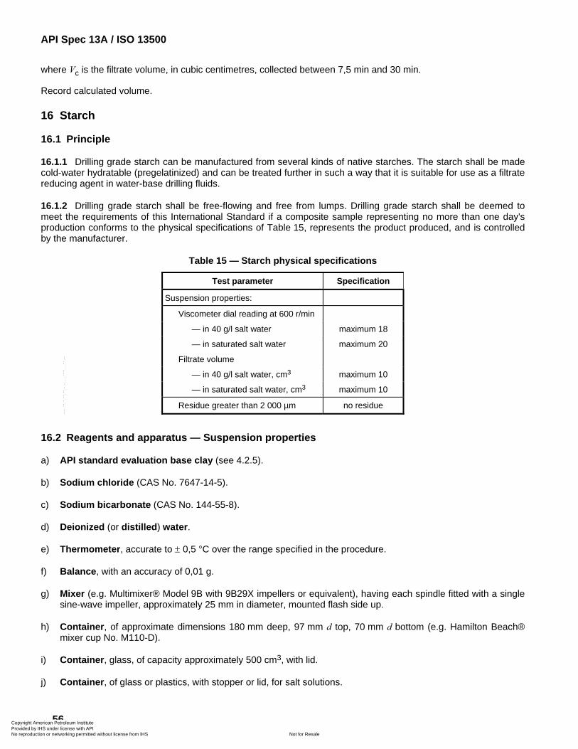
API Spec 13A / ISO 13500
56
where Vc is the filtrate volume, in cubic centimetres, collected between 7,5 min and 30 min.
Record calculated volume.
16 Starch
16.1 Principle
16.1.1 Drilling grade starch can be manufactured from several kinds of native starches. The starch shall be made cold-water hydratable (pregelatinized) and can be treated further in such a way that it is suitable for use as a filtrate reducing agent in water-base drilling fluids.
16.1.2 Drilling grade starch shall be free-flowing and free from lumps. Drilling grade starch shall be deemed to meet the requirements of this International Standard if a composite sample representing no more than one day's production conforms to the physical specifications of Table 15, represents the product produced, and is controlled by the manufacturer.
Table 15 — Starch physical specifications
Test parameter Specification
Suspension properties:
Viscometer dial reading at 600 r/min
— in 40 g/l salt water maximum 18
— in saturated salt water maximum 20
Filtrate volume
— in 40 g/l salt water, cm3 maximum 10
— in saturated salt water, cm3 maximum 10
Residue greater than 2 000 µm no residue
16.2 Reagents and apparatus — Suspension properties
a) API standard evaluation base clay (see 4.2.5).
b) Sodium chloride (CAS No. 7647-14-5).
c) Sodium bicarbonate (CAS No. 144-55-8).
d) Deionized (or distilled) water.
e) Thermometer, accurate to ± 0,5 °C over the range specified in the procedure.
f) Balance, with an accuracy of 0,01 g.
g) Mixer (e.g. Multimixer® Model 9B with 9B29X impellers or equivalent), having each spindle fitted with a single sine-wave impeller, approximately 25 mm in diameter, mounted flash side up.
h) Container, of approximate dimensions 180 mm deep, 97 mm d top, 70 mm d bottom (e.g. Hamilton Beach® mixer cup No. M110-D).
i) Container, glass, of capacity approximately 500 cm3, with lid.
j) Container, of glass or plastics, with stopper or lid, for salt solutions.
Copyright American Petroleum Institute Provided by IHS under license with API
Not for ResaleNo reproduction or networking permitted without license from IHS
--`,,```,,,,````-`-`,,`,,`,`,,`---
API Spec 13A / ISO 13500
57
k) Spatula.
l) Volumetric flask, of capacity 1 000 cm3.
m) Viscometer, motor-driven, direct-indicating, as referenced in ISO 10414-1.
n) Filter press, as referenced in ISO 10414-1.
o) Timers, two, mechanical or electrical, with accuracy of 0,1 min over test interval.
p) Graduated cylinders, three, of capacities (TC) of 10 cm3 ± 0,1 cm3, 100 cm3 ± 1 cm3 and 500 cm3 ± 5 cm3.
q) Constant temperature device (e.g. water bath) set at 20 °C to 25 °C; necessary if room temperature is not in the range of 20 °C to 25 °C.
16.3 Procedure — Viscometer reading in 40 g/l salt water
16.3.1 Prepare a 40 g/l salt water solution by adding 40 g ± 0,1 g of sodium chloride to a 1 000 cm3 volumetric flask and diluting with deionized water to the mark inscribed on the flask. Mix thoroughly.
16.3.2 Prepare a clay-based suspension by adding 350 cm3 ± 5 cm3 of the 40 g/l salt water solution to the container. Add 1,0 g ± 0,1 g of sodium bicarbonate and stir on the mixer for about 1 min.
16.3.3 Slowly add 35,0 g ± 0,1 g API standard evaluation base clay while stirring on the mixer.
16.3.4 After stirring 5 min ± 0,1 min, remove the container from mixer and scrape its sides with the spatula to dislodge any clay adhering to container walls. Be sure all clay clinging to the spatula is incorporated into the suspension.
16.3.5 Replace the container on the mixer and continue to stir. The container may need to be removed from the mixer and the sides scraped to dislodge any clay clinging to the container walls after another 5 min and another 10 min. Total stirring time after adding the clay shall equal 20 min ± 1 min.
16.3.6 Add 3,50 g ± 0,01 g of starch to the suspension while stirring on the mixer, adding at a uniform rate over about 60 s.
NOTE This is equivalent to 10,0 g/l ± 0,03 g/l.
16.3.7 After stirring 5 min ± 0,1 min, remove the container from the mixer and scrape its sides with the spatula to dislodge any starch adhering to container walls. Be sure all starch clinging to the spatula is incorporated into the suspension.
16.3.8 Replace the container on the mixer and continue to stir. The container may need to be removed from the mixer and the sides scraped to dislodge any starch clinging to the container walls after another 5 min and another 10 min. Total stirring time after adding the starch shall equal 20 min ± 1 min.
16.3.9 Age the suspension up to 24 h in a sealed or covered container at room temperature or in a constant temperature device. Record the storage temperature and storage duration.
16.3.10 After ageing, stir the suspension on the mixer for 5 min ± 0,1 min.
16.3.11 Immediately pour the suspension into the viscometer cup provided with the direct-indicating viscometer. The dial reading at the 600 r/min rotor speed setting of the viscometer shall be recorded when a constant value for 600 r/min is reached. The 600 r/min dial reading shall be taken at a suspension test temperature of 25 °C ± 1 °C. Record 600 r/min dial reading.
Copyright American Petroleum Institute Provided by IHS under license with API
Not for ResaleNo reproduction or networking permitted without license from IHS
--`,,```,,,,````-`-`,,`,,`,`,,`---
API Spec 13A / ISO 13500
58
16.4 Procedure — Filtrate volume of 40 g/l salt solution
16.4.1 Pour the suspension from 16.3 into the filter press cell. Before adding the suspension, be sure each part of the filter cell is dry and that all gaskets are not distorted or worn. The temperature of the suspension shall be 25 °C ± 1 °C. Pour the suspension to within about 13 mm of the top of the cell. Complete assembly of the filter press cell. Place the filter cell in the frame and close the relief valve. Place a container under the drain tube.
16.4.2 Set one timer for 7,5 min ± 0,1 min and the second timer for 30 min ± 0,1 min. Start both timers and adjust pressure on the cell at 690 kPa ± 35 kPa. Both of these steps shall be completed in less than 15 s. Pressure shall be supplied by compressed air, nitrogen or helium.
16.4.3 At 7,5 min ± 0,1 min on the first timer, remove the container and any adhering liquid on the drain tube and discard the filtrate. Place a dry 10 cm3 graduated cylinder under the drain tube and continue collecting filtrate to the end of the second timer set at 30 min. Remove the graduated cylinder and record the volume of filtrate collected.
16.5 Calculation — Filtrate volume of 40 g/l salt solution
Calculate V, the filtrate volume, in cubic centimetres, as given in Equation (16):
c2V V= ⋅ (16)
where Vc is the filtrate volume, in cubic centimetres, collected between 7,5 min and 30 min.
Record calculated volume.
16.6 Procedure — Viscometer reading in saturated salt solution
16.6.1 Prepare an ample volume of a saturated salt solution by thoroughly mixing in a suitable container 40 g to 45 g of sodium chloride per 100 cm3 ± 1 cm3 of deionized water. Allow solution to stand for approximately 1 h. Decant solution or filter it into a storage container.
16.6.2 Prepare a clay-based suspension by adding 350 cm3 ± 5 cm3 of the saturated salt solution to a container. Add 1,0 g ± 0,1 g of sodium bicarbonate and stir on the mixer for about 1 min.
16.6.3 Slowly add 35,0 g ± 0,1 g API standard evaluation base clay to the container while stirring on the mixer.
16.6.4 After stirring 5 min ± 0,1 min, remove the container from mixer and scrape its sides with the spatula to dislodge any clay adhering to the container walls. Be sure all clay clinging to the spatula is incorporated into the suspension.
16.6.5 Replace the container on the mixer and continue to stir. The container may need to be removed from the mixer and the sides scraped to dislodge any clay clinging to the container walls after another 5 min and another 10 min. Total stirring time after adding the clay shall equal 20 min ± 1 min.
16.6.6 Add 3,50 g ± 0,01 g of starch to the suspension while stirring on the mixer, adding at a uniform rate over about 60 s.
NOTE This is equivalent to 10,0 g/l ± 0,03 g/l.
16.6.7 After stirring 5 min ± 0,1 min, remove the container from the mixer and scrape its sides with the spatula to dislodge any starch adhering to container walls. Be sure all starch clinging to the spatula is incorporated into the suspension.
16.6.8 Replace the container on the mixer and continue to stir. The container may need to be removed from the mixer and the sides scraped to dislodge any starch clinging to the container walls after another 5 min and another 10 min. Total stirring time after adding the starch shall equal 20 min ± 1 min.
Copyright American Petroleum Institute Provided by IHS under license with API
Not for ResaleNo reproduction or networking permitted without license from IHS
--`,,```,,,,````-`-`,,`,,`,`,,`---
API Spec 13A / ISO 13500
59
16.6.9 Age the suspension up to 24 h in a sealed or covered container at room temperature or in a constant temperature device. Record storage temperature and storage duration.
16.6.10 After ageing, stir the suspension on the mixer for 5 min ± 0,1 min.
16.6.11 Immediately pour the suspension into the viscometer cup provided with the direct-indicating viscometer. The dial reading at the 600 r/min rotor speed setting of the viscometer shall be recorded when a constant value at 600 r/min is reached. The 600 r/min dial reading shall be taken at a suspension test temperature of 25 °C ± 1 °C. Record 600 r/min dial reading.
16.7 Procedure — Filtrate volume of saturated salt solution
16.7.1 Pour the suspension from 16.6 into a filter press cell. Before adding the suspension, be sure each part of the filter cell is dry and that all gaskets are not distorted or worn. The temperature of the suspension shall be 25 °C ± 1 °C. Pour the suspension to within about 13 mm of the top of the cell. Complete assembly of the filter press cell. Place the filter cell in the frame and close the relief valve. Place a container under the drain tube.
16.7.2 Set one timer for 7,5 min ± 0,1 min and the second timer for 30 min ± 0,1 min. Start both timers and adjust pressure on the cell at 690 kPa ± 35 kPa. Both of these steps shall be completed in less than 15 s. Pressure shall be supplied by compressed air, nitrogen or helium.
16.7.3 At 7,5 min ± 0,1 min on the first timer, remove the container and any adhering liquid on the drain tube and discard the filtrate. Place a dry 10 cm3 graduated cylinder under the drain tube and continue collecting filtrate to the end of the second timer set at 30 min. Remove the graduated cylinder and record the volume of filtrate collected.
16.8 Calculation — Filtrate volume of saturated salt solution
Calculate V, the filtrate volume, in cubic centimetres, as given in Equation (16):
c2V V= ⋅ (16)
where Vc is the filtrate volume, in cubic centimetres, collected between 7,5 min and 30 min.
Record calculated volume.
16.9 Reagents and apparatus — Residue greater than 2 000 µm
Sieve, 2 000 µm, of approximate diameter 203 mm, meeting the requirements of ASTM E11.
NOTE Supplier's verification that sieve conforms to ASTM E11 is satisfactory evidence of compliance.
16.10 Procedure — Residue greater than 2 000 µm
16.10.1 Weigh 25 g ± 0,1 g starch and transfer to the 2 000-µm sieve.
16.10.2 Shake for a maximum of 5 min.
10.10.3 Record the presence or absence of residue.
Copyright American Petroleum Institute Provided by IHS under license with API
Not for ResaleNo reproduction or networking permitted without license from IHS
--`,,```,,,,````-`-`,,`,,`,`,,`---
API Spec 13A / ISO 13500
60
Annex A (informative)
Mineral impurities in barite
The presence of certain accessory materials in a barite can produce undesirable performance in some drilling fluids. These accessory materials include naturally occurring minerals, such as gypsum, siderite, dolomite and pyrrhotite.
Gypsum is somewhat soluble in water and releases ions of calcium, one of the alkaline earth metals which are covered in this International Standard. Other minerals such as siderite, dolomite, and pyrrhotite are not covered in this International Standard, but can cause undesirable performance in some drilling fluids. These minerals, though not soluble in water to a significant degree, can release their anions in the presence of hydroxyl ions. Carbonate ions are released from siderite and dolomite in the presence of hydroxyl ions, and sulfide ions are released from pyrrhotite at high temperature in combination with high pH.
Because of the conditions under which these minerals are solubilized, not all drilling fluids will be detrimentally affected by their presence. Consequently, International Standards limiting their concentrations in barite have not been developed. When it is suspected that one or more are affecting mud performance, procedures for determining their concentration in the barite can be found in API RP 13K.
Copyright American Petroleum Institute Provided by IHS under license with API
Not for ResaleNo reproduction or networking permitted without license from IHS
--`,,```,,,,````-`-`,,`,,`,`,,`---
API Spec 13A / ISO 13500
61
Annex B (informative)
Test precision
B.1 Description
B.1.1 General
Precision statements for this International Standard tests are presented in this annex for the following materials:
a) barite;
b) haematite;
c) bentonite;
d) non-treated bentonite;
e) OCMA-grade Bentonite;
f) attapulgite;
g) sepiolite;
h) technical grade low-viscosity CMC;
i) technical grade high-viscosity CMC;
j) starch.
The precision values in this annex do not represent what might be expected from any random laboratory. Rather, they reflect the precision obtained by personnel who are trained and experienced in running the tests using equipment that is in good working order and in calibration.
Any laboratory that wishes to test materials for conformance to this International Standard shall demonstrate at least the degree of test precision given in this annex. Calibration Barite and Test Calibration Bentonite are available through the API offices (see 4.2.1) for use by laboratories to determine their test precision.
B.1.2 Considerations for manufacturers and users
The precision data in Tables B.1 through B.10 reflect the fact that the standard test methods are subject to normal test variability. This variability can lead to conflicts between a manufacturer and a user based on their respective test results on the same sample of material.
The precision data indicate the maximum expected difference between two test results on the same sample, both within and between laboratories, at the 95 % confidence level.
B.2 Basis
The limits in Tables B.1, B.3, B.4, B.5, B.8, B.9 and B.10 were determined from interlaboratory studies conducted from 1988 to 1991. The data analysis is given in API Research Reports 88-30, 89-30 and 90-30. The studies were designed and conducted by an independent consulting laboratory under contract to the API. The project was
Copyright American Petroleum Institute Provided by IHS under license with API
Not for ResaleNo reproduction or networking permitted without license from IHS
--`,,```,,,,````-`-`,,`,,`,`,,`---
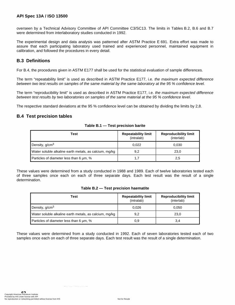
API Spec 13A / ISO 13500
62
overseen by a Technical Advisory Committee of API Committee C3/SC13. The limits in Tables B.2, B.6 and B.7 were determined from interlaboratory studies conducted in 1992.
The experimental design and data analysis was patterned after ASTM Practice E 691. Extra effort was made to assure that each participating laboratory used trained and experienced personnel, maintained equipment in calibration, and followed the procedures in every detail.
B.3 Definitions
For B.4, the procedures given in ASTM E177 shall be used for the statistical evaluation of sample differences.
The term “repeatability limit” is used as described in ASTM Practice E177, i.e. the maximum expected difference between two test results on samples of the same material by the same laboratory at the 95 % confidence level.
The term “reproducibility limit” is used as described in ASTM Practice E177, i.e. the maximum expected difference between test results by two laboratories on samples of the same material at the 95 % confidence level.
The respective standard deviations at the 95 % confidence level can be obtained by dividing the limits by 2,8.
B.4 Test precision tables
Table B.1 — Test precision barite
Test Repeatability limit (intralab)
Reproducibility limit (interlab)
Density, g/cm3 0,022 0,030
Water soluble alkaline earth metals, as calcium, mg/kg 9,2 23,0
Particles of diameter less than 6 µm, % 1,7 2,5
These values were determined from a study conducted in 1988 and 1989. Each of twelve laboratories tested each of three samples once each on each of three separate days. Each test result was the result of a single determination.
Table B.2 — Test precision haematite
Test Repeatability limit (intralab)
Reproducibility limit (interlab)
Density, g/cm3 0,026 0,050
Water soluble alkaline earth metals, as calcium, mg/kg 9,2 23,0
Particles of diameter less than 6 µm, % 0,9 3,4
These values were determined from a study conducted in 1992. Each of seven laboratories tested each of two samples once each on each of three separate days. Each test result was the result of a single determination.
Copyright American Petroleum Institute Provided by IHS under license with API
Not for ResaleNo reproduction or networking permitted without license from IHS
--`,,```,,,,````-`-`,,`,,`,`,,`---
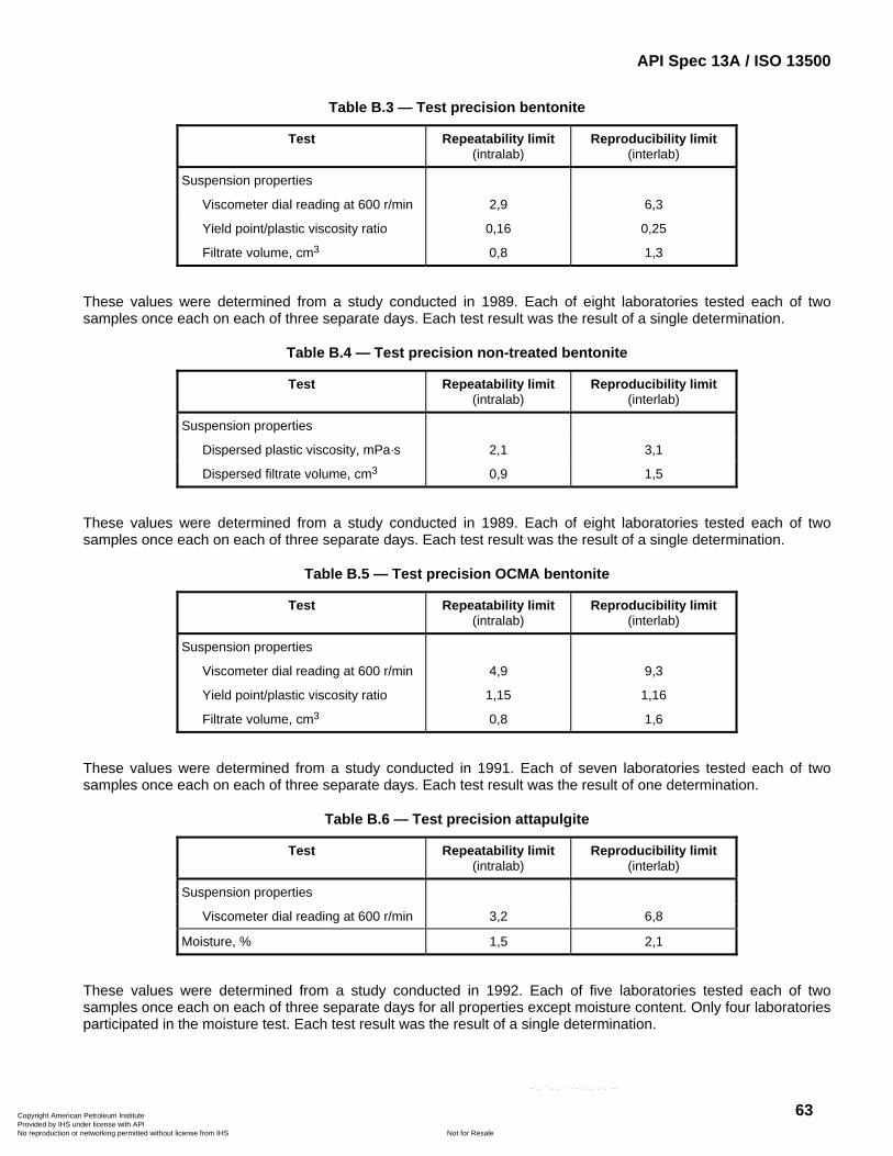
API Spec 13A / ISO 13500
63
Table B.3 — Test precision bentonite
Test Repeatability limit (intralab)
Reproducibility limit (interlab)
Suspension properties
Viscometer dial reading at 600 r/min 2,9 6,3
Yield point/plastic viscosity ratio 0,16 0,25
Filtrate volume, cm3 0,8 1,3
These values were determined from a study conducted in 1989. Each of eight laboratories tested each of two samples once each on each of three separate days. Each test result was the result of a single determination.
Table B.4 — Test precision non-treated bentonite
Test Repeatability limit (intralab)
Reproducibility limit (interlab)
Suspension properties
Dispersed plastic viscosity, mPa·s 2,1 3,1
Dispersed filtrate volume, cm3 0,9 1,5
These values were determined from a study conducted in 1989. Each of eight laboratories tested each of two samples once each on each of three separate days. Each test result was the result of a single determination.
Table B.5 — Test precision OCMA bentonite
Test Repeatability limit (intralab)
Reproducibility limit (interlab)
Suspension properties
Viscometer dial reading at 600 r/min 4,9 9,3
Yield point/plastic viscosity ratio 1,15 1,16
Filtrate volume, cm3 0,8 1,6
These values were determined from a study conducted in 1991. Each of seven laboratories tested each of two samples once each on each of three separate days. Each test result was the result of one determination.
Table B.6 — Test precision attapulgite
Test Repeatability limit (intralab)
Reproducibility limit (interlab)
Suspension properties
Viscometer dial reading at 600 r/min 3,2 6,8
Moisture, % 1,5 2,1
These values were determined from a study conducted in 1992. Each of five laboratories tested each of two samples once each on each of three separate days for all properties except moisture content. Only four laboratories participated in the moisture test. Each test result was the result of a single determination.
Copyright American Petroleum Institute Provided by IHS under license with API
Not for ResaleNo reproduction or networking permitted without license from IHS
--`,,```,,,,````-`-`,,`,,`,`,,`---
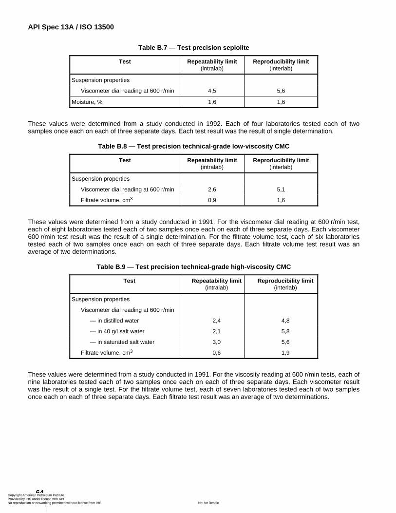
API Spec 13A / ISO 13500
64
Table B.7 — Test precision sepiolite
Test Repeatability limit (intralab)
Reproducibility limit (interlab)
Suspension properties
Viscometer dial reading at 600 r/min 4,5 5,6
Moisture, % 1,6 1,6
These values were determined from a study conducted in 1992. Each of four laboratories tested each of two samples once each on each of three separate days. Each test result was the result of single determination.
Table B.8 — Test precision technical-grade low-viscosity CMC
Test Repeatability limit (intralab)
Reproducibility limit (interlab)
Suspension properties
Viscometer dial reading at 600 r/min 2,6 5,1
Filtrate volume, cm3 0,9 1,6
These values were determined from a study conducted in 1991. For the viscometer dial reading at 600 r/min test, each of eight laboratories tested each of two samples once each on each of three separate days. Each viscometer 600 r/min test result was the result of a single determination. For the filtrate volume test, each of six laboratories tested each of two samples once each on each of three separate days. Each filtrate volume test result was an average of two determinations.
Table B.9 — Test precision technical-grade high-viscosity CMC
Test Repeatability limit(intralab)
Reproducibility limit (interlab)
Suspension properties
Viscometer dial reading at 600 r/min
— in distilled water 2,4 4,8
— in 40 g/l salt water 2,1 5,8
— in saturated salt water 3,0 5,6
Filtrate volume, cm3 0,6 1,9
These values were determined from a study conducted in 1991. For the viscosity reading at 600 r/min tests, each of nine laboratories tested each of two samples once each on each of three separate days. Each viscometer result was the result of a single test. For the filtrate volume test, each of seven laboratories tested each of two samples once each on each of three separate days. Each filtrate test result was an average of two determinations.
Copyright American Petroleum Institute Provided by IHS under license with API
Not for ResaleNo reproduction or networking permitted without license from IHS
--`,,```,,,,````-`-`,,`,,`,`,,`---
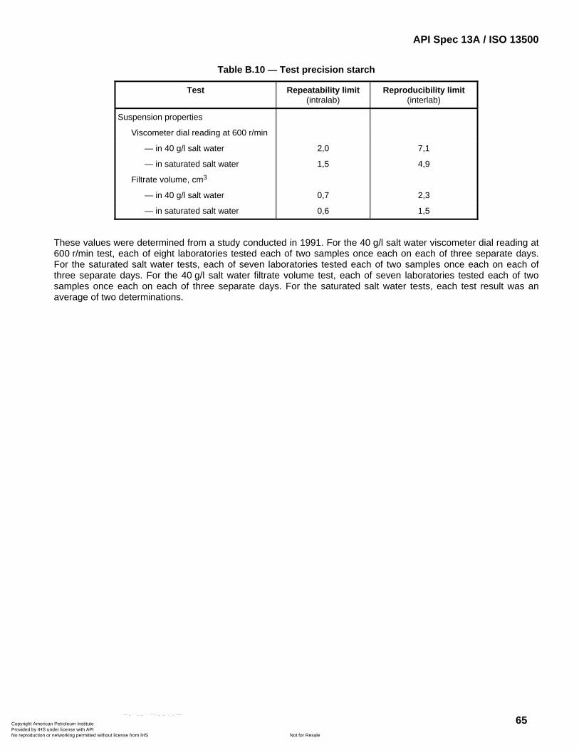
API Spec 13A / ISO 13500
65
Table B.10 — Test precision starch
Test Repeatability limit (intralab)
Reproducibility limit (interlab)
Suspension properties
Viscometer dial reading at 600 r/min
— in 40 g/l salt water 2,0 7,1
— in saturated salt water 1,5 4,9
Filtrate volume, cm3
— in 40 g/l salt water 0,7 2,3
— in saturated salt water 0,6 1,5
These values were determined from a study conducted in 1991. For the 40 g/l salt water viscometer dial reading at 600 r/min test, each of eight laboratories tested each of two samples once each on each of three separate days. For the saturated salt water tests, each of seven laboratories tested each of two samples once each on each of three separate days. For the 40 g/l salt water filtrate volume test, each of seven laboratories tested each of two samples once each on each of three separate days. For the saturated salt water tests, each test result was an average of two determinations.
Copyright American Petroleum Institute Provided by IHS under license with API
Not for ResaleNo reproduction or networking permitted without license from IHS
--`,,```,,,,````-`-`,,`,,`,`,,`---
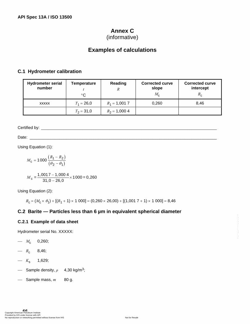
API Spec 13A / ISO 13500
66
Annex C (informative)
Examples of calculations
C.1 Hydrometer calibration
Hydrometer serial number
Temperature t
°C
Reading R
Corrected curve slope
Mc
Corrected curve intercept
Bc
xxxxx T1 = 26,0 R1 = 1,001 7 0,260 8,46
T2 = 31,0 R2 = 1,000 4
Certified by: _____________________________________________________________________________
Date: __________________________________________________________________________________
Using Equation (1):
( )( )
1 2c
2 11000
R RM
θ θ−
=−
cM −×
−1,0017 1,000 4 = 1000 = 0,260
31,0 26,0
Using Equation (2):
Bc = (Mc × θ1) + [(R1 + 1) × 1 000] = (0,260 × 26,00) + [(1,001 7 + 1) × 1 000] = 8,46
C.2 Barite — Particles less than 6 µm in equivalent spherical diameter
C.2.1 Example of data sheet
Hydrometer serial No. XXXXX:
⎯ Mc 0,260;
⎯ Bc 8,46;
⎯ Ks 1,629;
⎯ Sample density, ρ 4,30 kg/m3;
⎯ Sample mass, m 80 g.
Copyright American Petroleum Institute Provided by IHS under license with API
Not for ResaleNo reproduction or networking permitted without license from IHS
--`,,```,,,,````-`-`,,`,,`,`,,`---
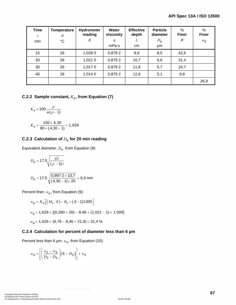
API Spec 13A / ISO 13500
67
Time t
min
Temperature θ
°C
Hydrometer reading
R
Water viscosity
η mPa·s
Effective depth
L cm
Particle diameter
De µm
% Finer
W
% Finer
w6
10 26 1,028 0 0,879 2 8,9 8,5 42,6
20 26 1,021 0 0,879 2 10,7 6,6 31,4
30 26 1,017 0 0,879 2 11,8 5,7 24,7
40 26 1,014 0 0,879 2 12,6 5,1 9,8
26,9
C.2.2 Sample constant, Ks , from Equation (7)
( )s 1001
Km
ρρ
=−
( )s100 4,30 1,629
80 4,30 1K ×
= =× −
C.2.3 Calculation of De for 20 min reading
Equivalent diameter, De, from Equation (8):
( )e 17,51
LDt
ηρ
=−
( )0,897 2 10,717,5 6,6 m4,30 1
D ×= =
− ×e m 20
Percent finer, wa, from Equation (9):
( ) ( )a s c c 1 1000w K M B Rθ⎡ ⎤= ⋅ − + −⎣ ⎦
wa = 1,629 × [(0,260 × 26) − 8,46 + (1,021 − 1) × 1 000]
wa = 1,629 × (6,76 − 8,46 + 21,0) = 31,4 %
C.2.4 Calculation for percent of diameter less than 6 µm
Percent less than 6 µm, w4, from Equation (10):
( )2 34 3
2 3
w ww D
D D
⎡ ⎤⎛ ⎞−= −⎢ ⎥⎜ ⎟
−⎢ ⎥⎝ ⎠⎣ ⎦6 3w+
Copyright American Petroleum Institute Provided by IHS under license with API
Not for ResaleNo reproduction or networking permitted without license from IHS
--`,,```,,,,````-`-`,,`,,`,`,,`---
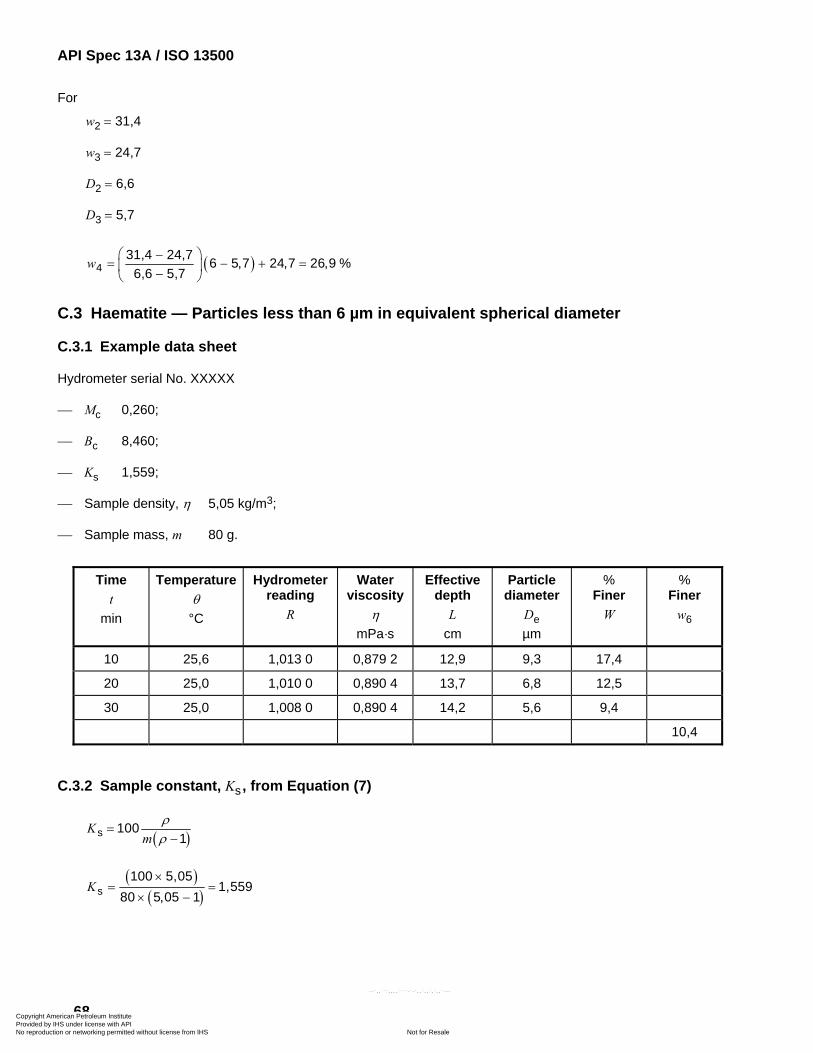
API Spec 13A / ISO 13500
68
For
w2 = 31,4
w3 = 24,7
D2 = 6,6
D3 = 5,7
( )431,4 24,7 6 5,7 24,7 26,9 %
6,6 5,7w
⎛ ⎞−= − + =⎜ ⎟−⎝ ⎠
C.3 Haematite — Particles less than 6 µm in equivalent spherical diameter
C.3.1 Example data sheet
Hydrometer serial No. XXXXX
⎯ Mc 0,260;
⎯ Bc 8,460;
⎯ Ks 1,559;
⎯ Sample density, η 5,05 kg/m3;
⎯ Sample mass, m 80 g.
Time t
min
Temperature θ
°C
Hydrometer reading
R
Water viscosity
η mPa·s
Effective depth
L cm
Particle diameter
De µm
% Finer
W
% Finer
w6
10 25,6 1,013 0 0,879 2 12,9 9,3 17,4
20 25,0 1,010 0 0,890 4 13,7 6,8 12,5
30 25,0 1,008 0 0,890 4 14,2 5,6 9,4
10,4
C.3.2 Sample constant, Ks , from Equation (7)
( )s 1001
Km
ρρ
=−
( )( )s
100 5,051,559
80 5,05 1K
×= =
× −
Copyright American Petroleum Institute Provided by IHS under license with API
Not for ResaleNo reproduction or networking permitted without license from IHS
--`,,```,,,,````-`-`,,`,,`,`,,`---
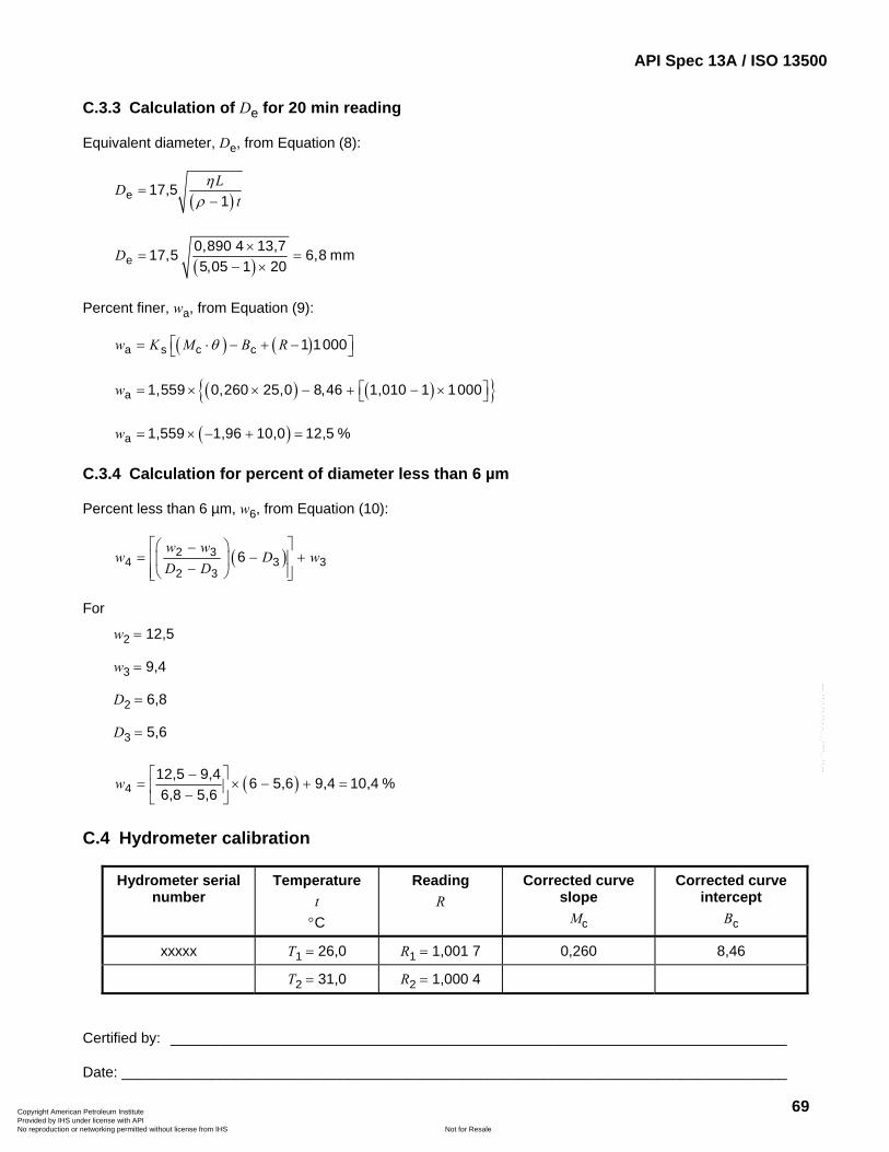
API Spec 13A / ISO 13500
69
C.3.3 Calculation of De for 20 min reading
Equivalent diameter, De, from Equation (8):
( )e 17,51
LDt
ηρ
=−
( )e0,890 4 13,717,5 6,8 mm5,05 1 20
D ×= =
− ×
Percent finer, wa, from Equation (9):
( ) ( )a s c c 1 1000w K M B Rθ⎡ ⎤= ⋅ − + −⎣ ⎦
( ) ( ){ }a 1,559 0,260 25,0 8,46 1,010 1 1000w ⎡ ⎤= × × − + − ×⎣ ⎦
( )a 1,559 1,96 10,0 12,5 %w = × − + =
C.3.4 Calculation for percent of diameter less than 6 µm
Percent less than 6 µm, w6, from Equation (10):
( )2 34 3
2 3
w ww D
D D
⎡ ⎤⎛ ⎞−= −⎢ ⎥⎜ ⎟
−⎢ ⎥⎝ ⎠⎣ ⎦6 3w+
For
w2 = 12,5
w3 = 9,4
D2 = 6,8
D3 = 5,6
( )412,5 9,4 6 5,6 9,4 10,4 %6,8 5,6
w⎡ ⎤−
= × − + =⎢ ⎥−⎣ ⎦
C.4 Hydrometer calibration
Hydrometer serial number
Temperature t
°C
Reading R
Corrected curve slope
Mc
Corrected curve intercept
Bc
xxxxx T1 = 26,0 R1 = 1,001 7 0,260 8,46
T2 = 31,0 R2 = 1,000 4
Certified by: ____________________________________________________________________________
Date: __________________________________________________________________________________
Copyright American Petroleum Institute Provided by IHS under license with API
Not for ResaleNo reproduction or networking permitted without license from IHS
--`,,```,,,,````-`-`,,`,,`,`,,`---
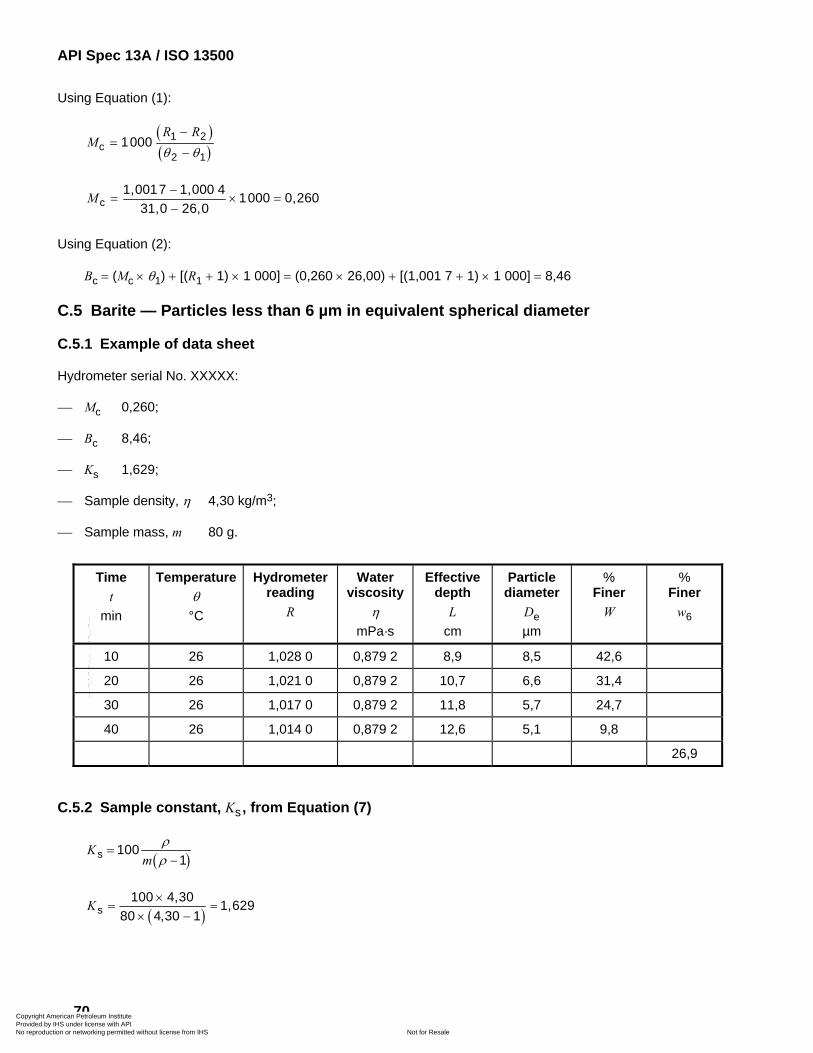
API Spec 13A / ISO 13500
70
Using Equation (1):
( )( )
1 2c
2 11000
R RM
θ θ−
=−
cM −= ×
−1,0017 1,000 4 1000 0,260
31,0 26,0=
Using Equation (2):
Bc = (Mc × θ1) + [(R1 + 1) × 1 000] = (0,260 × 26,00) + [(1,001 7 + 1) × 1 000] = 8,46
C.5 Barite — Particles less than 6 µm in equivalent spherical diameter
C.5.1 Example of data sheet
Hydrometer serial No. XXXXX:
⎯ Mc 0,260;
⎯ Bc 8,46;
⎯ Ks 1,629;
⎯ Sample density, η 4,30 kg/m3;
⎯ Sample mass, m 80 g.
Time t
min
Temperature θ
°C
Hydrometer reading
R
Water viscosity
η mPa·s
Effective depth
L cm
Particle diameter
De µm
% Finer
W
% Finer
w6
10 26 1,028 0 0,879 2 8,9 8,5 42,6
20 26 1,021 0 0,879 2 10,7 6,6 31,4
30 26 1,017 0 0,879 2 11,8 5,7 24,7
40 26 1,014 0 0,879 2 12,6 5,1 9,8
26,9
C.5.2 Sample constant, Ks , from Equation (7)
( )s 1001
Km
ρρ
=−
( )s100 4,30 1,629
80 4,30 1K ×
= =× −
Copyright American Petroleum Institute Provided by IHS under license with API
Not for ResaleNo reproduction or networking permitted without license from IHS
--`,,```,,,,````-`-`,,`,,`,`,,`---
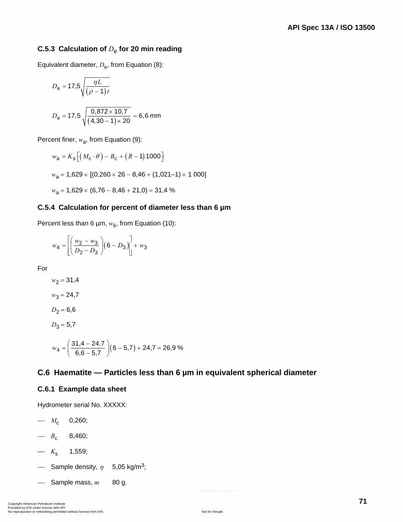
API Spec 13A / ISO 13500
71
C.5.3 Calculation of De for 20 min reading
Equivalent diameter, De, from Equation (8):
( )e 17,51
LDt
ηρ
=−
( )m
4,30 1D ×
= =− ×e
0,872 10,717,5 6,6 m20
Percent finer, wa, from Equation (9):
( ) ( )a s c c 1 1000w K M B Rθ⎡ ⎤= ⋅ − + −⎣ ⎦
wa = 1,629 × [(0,260 × 26 − 8,46 + (1,021–1) × 1 000]
wa = 1,629 × (6,76 − 8,46 + 21,0) = 31,4 %
C.5.4 Calculation for percent of diameter less than 6 µm
Percent less than 6 µm, w6, from Equation (10):
( )2 34 3
2 3
w ww D
D D
⎡ ⎤⎛ ⎞−= −⎢ ⎥⎜ ⎟
−⎢ ⎥⎝ ⎠⎣ ⎦6 3w+
For
w2 = 31,4
w3 = 24,7
D2 = 6,6
D3 = 5,7
( )431,4 24,7 6 5,7 24,7 26,9 %
6,6 5,7w
⎛ ⎞−= − + =⎜ ⎟−⎝ ⎠
C.6 Haematite — Particles less than 6 µm in equivalent spherical diameter
C.6.1 Example data sheet
Hydrometer serial No. XXXXX:
⎯ Mc 0,260;
⎯ Bc 8,460;
⎯ Ks 1,559;
⎯ Sample density, η 5,05 kg/m3;
⎯ Sample mass, m 80 g.
Copyright American Petroleum Institute Provided by IHS under license with API
Not for ResaleNo reproduction or networking permitted without license from IHS
--`,,```,,,,````-`-`,,`,,`,`,,`---
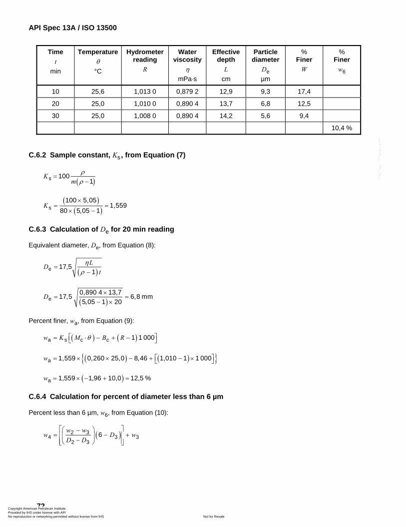
API Spec 13A / ISO 13500
72
Time t
min
Temperature θ
°C
Hydrometer reading
R
Water viscosity
η mPa·s
Effective depth
L cm
Particle diameter
De µm
% Finer
W
% Finer
w6
10 25,6 1,013 0 0,879 2 12,9 9,3 17,4
20 25,0 1,010 0 0,890 4 13,7 6,8 12,5
30 25,0 1,008 0 0,890 4 14,2 5,6 9,4
10,4 %
C.6.2 Sample constant, Ks , from Equation (7)
( )s 1001
Km
ρρ
=−
( )( )s
100 5,051,559
80 5,05 1K
×= =
× −
C.6.3 Calculation of De for 20 min reading
Equivalent diameter, De, from Equation (8):
( )e 17,51
LDt
ηρ
=−
( )e0,890 4 13,717,5 6,8 mm5,05 1 20
D ×= =
− ×
Percent finer, wa, from Equation (9):
( ) ( )a s c c 1 1 000w K M B Rθ⎡ ⎤= ⋅ − + −⎣ ⎦
( ) ( ){ }a 1,559 0,260 25,0 8,46 1,010 1 1 000w ⎡ ⎤= × × − + − ×⎣ ⎦
( )a 1,559 1,96 10,0 12,5 %w = × − + =
C.6.4 Calculation for percent of diameter less than 6 µm
Percent less than 6 µm, w6, from Equation (10):
( )2 34 3
2 3
w ww D
D D
⎡ ⎤⎛ ⎞−= −⎢ ⎥⎜ ⎟
−⎢ ⎥⎝ ⎠⎣ ⎦6 3w+
Copyright American Petroleum Institute Provided by IHS under license with API
Not for ResaleNo reproduction or networking permitted without license from IHS
--`,,```,,,,````-`-`,,`,,`,`,,`---
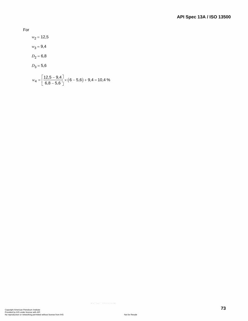
API Spec 13A / ISO 13500
73
For
w2 = 12,5
w3 = 9,4
D2 = 6,8
D3 = 5,6
( )412,5 9,4 6 5,6 9,4 10,4 %6,8 5,6
w⎡ ⎤−
= × − + =⎢ ⎥−⎣ ⎦
Copyright American Petroleum Institute Provided by IHS under license with API
Not for ResaleNo reproduction or networking permitted without license from IHS
--`,,```,,,,````-`-`,,`,,`,`,,`---
API Spec 13A / ISO 13500
74
Annex D (Informative)
API Monogram
D.0 Introduction
The API Monogram Program allows an API Licensee to apply the API Monogram to products. The use of the Monogram on products constitutes a representation and warranty by the Licensee to purchasers of the products that, on the date indicated, the products were produced in accordance with a verified quality management system and in accordance with an API product specification. The API Monogram Program delivers significant value to the international oil and gas industry by linking the verification of an organization's quality management system with the demonstrated ability to meet specific product specification requirements.
When used in conjunction with the requirements of the API License Agreement, API Specification Q1, including Annex A, defines the requirements for those organizations who wish to voluntarily obtain an API License to provide API monogrammed products in accordance with an API product specification.
API Monogram Program Licenses are issued only after an on-site audit has verified that the Licensee conforms to the requirements described in API Specification Q1 in total.
For information on becoming an API Monogram Licensee, please contact API, Certification Programs, 1220 L Street, N. W., Washington, DC 20005 or call 202-682-8000 or by email at [email protected].
D.1 API Monogram Marking Requirements These marking requirements apply only to those API licensees wishing to mark their products with the API Monogram.
D.1.2 Bulk Material The API Monogram, if applied, will be placed on the delivery ticket accompanying each bulk shipment in a position of prominence.
D.2.1 Uncontrolled material If the licensee receives material not under his control, and this material conforms to the chemical and physical requirements of the material specification in this standard and API Specification Q1, the API monogram may be applied.
Copyright American Petroleum Institute Provided by IHS under license with API
Not for ResaleNo reproduction or networking permitted without license from IHS
--`,,```,,,,````-`-`,,`,,`,`,,`---
API Spec 13A / ISO 13500
75
Bibliography
[1] ISO 31 (all parts), Quantities and units
[2] ISO 3310-1, Test sieves — Technical requirements and testing — Part 1: Test sieves of metal wire cloth
[3] ISO 10241, International terminology standards — Preparation and layout
[4] API RP 13K, Recommended Practice for Chemical Analysis of Barite
[5] ASTM E691, Standard Practice for Conducting an Interlaboratory Study to Determine the Precision of a Test Method
[6] API Spec 13A, Oil-Well Drilling-Fluid Materials, 16th Edition, December 1, 2003
[7] API 88-30, 1988. Repeatability and reproducibility study of barite and bentonite
[8] API 89-30, 1989. Repeatability and reproducibility study of haematite, non-treated bentonite, attapulgite, and sepiolite
[9] API 90-30, 1990. Repeatability and reproducibility study of OCMA bentonite, technical-grade low-viscosity carboxymethylcellulose, technical-grade high-viscosity carboxymethylcellulose, and starch
[10] KOROSI, A. and FABUSS, B. Analytical Chemistry, Vol 40 No. 1, Jan. 1968, “Viscosity of Liquid Water from 25 °C to 150 °C”, p. 162
Copyright American Petroleum Institute Provided by IHS under license with API
Not for ResaleNo reproduction or networking permitted without license from IHS
--`,,```,,,,````-`-`,,`,,`,`,,`---

Copyright American Petroleum Institute Provided by IHS under license with API
Not for ResaleNo reproduction or networking permitted without license from IHS
--`,,```,,,,````-`-`,,`,,`,`,,`---

Product No: GX13A17
Copyright American Petroleum Institute Provided by IHS under license with API
Not for ResaleNo reproduction or networking permitted without license from IHS
--`,,```,,,,````-`-`,,`,,`,`,,`---