is0206 final 92004 - faria beede instruments,...
TRANSCRIPT
INSTRUMENTSUncasville, CT
Owner’s ManualMonaco Serial Bus Vehicle Information SystemElegant Conventional LookAdvanced Digital Features
• Odometer
• Two Trip Odometers
• Engine Hourmeter
• Clock• Critical Vehicle Data ISO206
REV. A ECR4663 7/2004
Table of ContentsQuick Operation: Page 2
To turn on the system: Page 2
To turn off the system: Page 2
To turn on instrument lighting: Page 2
To turn off instrument lighting: Page 2
To change the lighting intensity, Page 2
To disable the audible alarm in normal mode: Page 2
To change the LCD display Page 2
(Odometer, Trip odometer 1, Trip odometer 2, Engine Hour, Clock):
To reset Trip odometer 1: Page 3
To reset Trip odometer 2: Page 3
To set up the clock: Page 3
Gateway System Specifications: Page 4
System Description Page 4
Parameters and Features: Page 4
System Elements Page 5
System Operation: Page 6
Speedometer: Page 6
1. System Clock Page 6
2. Turning the Gateway system ON/OFF Page 6
3. Changing Modes Page 7
Self Test mode Page 7
To exit the Self Test mode: Page 7
Gateway ID checking mode Page 7
To exit the gateway ID check mode: Page 7
4. Normal Mode: Page 7
Illumination Page 8
Select Function: Page 9
Figure 1 Functions Diagram Page 9
Reset Trip Odometer 1 & 2 Page 10
Setting the Clock Page 10
Warning Messages Page 11
Disable Audible Alarm Page 12
5. Self Test Mode: Page 12
To Enter Self Test Mode: Page 12
To Exit Self Test Mode: Page 12
Appendix 1. Installation and Wiring Page 14
Figure 2 Executive Wiring Diagaram Page 15
Figure 3 Signature Wiring Diagaram Page 16
Typical 2-device J1939 Network Topology Page 17
Typical Multi-device J1939 Network Topology Page 18

J1939 Gateway (GW0015) System Manual (Monaco Executive and Signature coaches)Important:1. Please read this manual before you install or use the Faria J1939 gateway system.2. Two and Only Two 120-ohm termination resistors across the CAN-High and CAN-Low wires at each end of the vehicle network are required per SAE-J1939/11. 3. Installation by a qualified service technician is recommended. Connecting the gateway incorrectly could void warranties.4. A visual inspection of this product for damage during shipping is recommended.5. Follow all safety warnings of the vehicle/engine manufacturer.
Quick operation:1. To turn on the system: Turn the ignition key to “ON” position.
2. To turn off the system: Turn the ignition key to “OFF” position.
3. To turn on instrument lighting: Turn on the light switch on the vehicle instrument panel.
4. To turn off instrument lighting: Turn off the light switch on the vehicle instrument panel.
5. To change the lighting intensity, (requires the light switch be turned on):
a. Turn on the light switch as described in item 3 above.
b. Pushing the “UP” button on the speedometer will increase the intensity of the instrument lighting. When maximum intensity is reached no further changes can be effected by pushing the “UP” button.
c. Pushing the “DOWN” button on the speedometer will decrease the intensity of the instrument lighting. When minimum intensity is reached no further changes can be effected by pressing the “DOWN button.
6. To disable the audible alarm in normal mode: PUSH and HOLD both the “UP” and the “DOWN” buttons on the speedometer until the beep stops.
7. To change the LCD display (Odometer, Trip odometer 1, Trip odometer 2, Engine Hour, Clock): a. Pressing the “M” button on the speedometer will select the next LCD display.
b. Press the “M” button repeatedly until desired function is displayed. The gateway will switch to a screen displaying the function data in 2 seconds after button is pressed.
Page 2

8. To reset Trip odometer 1: a. See 7 above. When “TRIP1” is displayed on the LCD, wait 2 seconds to let the LCD screen switch to the trip mileage.
b. Once the mileage is displayed, push and hold the “M” button on the speedometer until the number re-sets to zero.
9. To reset Trip odometer 2: a. See 7 above. When “TRIP 2” is displayed on the LCD, wait 2 seconds to let the LCD screen switch to the trip mileage.
b.Once the mileage is displayed, push and hold the “M” button on the speedometer until the number re-sets to zero.
10. To set up the clock:a. See 7 above. Select “CLOCK” as the current display on the LCD, wait 2 seconds, the clock will be displayed on the LCD.
b. Push and Hold the “M” button on the speedometer until the clock starts blinking,
c. Push the “UP” button to change Minutes,
d. Push the “DOWN” button to change Hours,
e. After the clock is set, push and hold the “M” button on the speedometer until the clock stops blinking.
Page 3
Gateway System Specifications:For correct operation it is assumed your vehicle’s CAN Bus is SAE J1939 compliant. Instrumentation and Warning Light data is broadcast on the Faria Serial bus.Operation voltage: +12 V DC or +24 V DC; +12 V DC (10 V DC (Min.) to 16 V DC (max.))+24 V DC (20 V DC (Min.) to 32 V DC (max.))Maximum Current with maximum backlight: < 1500 mA @ 12 V;Minimum Current at switch off status: < 10 mA @ 12 V;Operational temperature: -40˚ F to 185˚ F (-40˚ C to 85˚ C);Storage temperature: -40˚ F to 185˚ F (-40˚ C to 85˚ C);
System Description♦ Monitors electronically controlled engines/transmissions/ABS using SAE J1939 Controller Area Network (CAN) protocol.♦ Monitors Centroid 0-90 Ohm compatible fuel sender.♦ Monitors two 0-150 PSI brake air pressure lines.♦ Monitors positive switch inputs, such as: Water in Fuel Warning, Step Out, High Beam, Left Turn, Right Turn, ABS TAG Error Warning and vehicle light switch.♦ Monitors negative switch inputs, such as: Parking Brake, Gen Door Open, Low Air Warning, Antenna Up, Maintenance Warning and ABS Warning.♦ Includes indicator light arrays showing: left/right turn signal, Ant up signal, high beam indicator, parking brake indicator, step out indicator, Gen. door open, and “cruise control” active indicator, ABS and ABS Tag warning indicators.
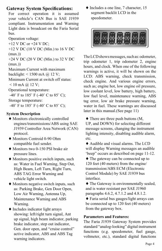
♦ Includes a one line, 7 character, 15 segment backlit LCD in the speedometer.
The LCD shows messages, such as: odometer, trip odometer 1, trip odometer 2, engine hours, and clock. When one of the following warnings is active, it will be shown on the LCD: ABS warning, check transmission, check engine. And various engine errors, such as; engine hot, low engine oil pressure, low coolant level, low battery, high battery, low fuel level, maintenance warning, ABS tag error, low air brake pressure warning, water in fuel. These warnings are discussed later in this manual.(See page 11)
♦ There are three push buttons (M, UP, and DOWN) for selecting different message screens, changing the instrument lighting intensity, disabling audible alarm, etc.♦ Audible and visual alarms. The LCD will display Warning messages an audible ‘beep” occurs as described on page 11-12.♦ The gateway can be connected up to 120 feet (40 meters) from the engine/transmission/ABS ECM (Electronic Control Module) by SAE J1939 bus interface.♦ The Gateway is environmentally sealed, and is water resistant per SAE J1960 paragraphs 4.6.2, 4.7.1.2 and 4.8.1.2.♦ Faria serial bus gauges/light arrays can be connected up to 120 feet (40 meters) from the gateway box.
Parameters and Features:The Faria J1939 Gateway System provides standard “analog-looking” digital instrument functions (e.g. speedometer, fuel gauge, voltmeter, etc.), standard digital functions
Page 4
(e.g. odometer, engine hours, etc.), and many additional functions (e.g. clock, brake air pressure monitoring, etc.).
The gateway is the hub of all system operations. A significant amount of data is received at the gateway from the engine / transmission / ABS (Anti-lock Brake System) via the vehicle’s SAE J1939 CAN bus.
The J1939 information includes:♦ Engine RPM, ♦ Battery voltage, ♦ Vehicle Wheel based speed,♦ Vehicle cruise control active,♦ Engine operation hours,♦ Engine oil pressure,♦ Engine Turbo boost pressure,♦ Engine Coolant temperature,♦ Engine Active Diagnostic Trouble Codes (DM1),♦ Amber warning lamp status,♦ Red stop lamp status,♦ Transmission oil temperature, ♦ Transmission Active Diagnostic Trouble Codes (DM1),♦ ABS Active Diagnostic Trouble Codes (DM1)
Note 1: The Active Diagnostic Trouble Codes (DM1) messages are heavily dependent on the electronic control units of the Engine/Transmission/ABS. The message contents will change from time to time. The gateway will translate most of these Active Diagnostic Trouble code messages (if they are sent to the J1939 bus) to a readable warning message on the speedometer LCD accompanied by visible and audible warning signals.
Note 2: For diagnostic purposes, please use dedicated diagnostic tools!
In addition, the gateway provides:♦ Clock,♦ Odometer♦ Trip odometers (Trip 1 and Trip 2)
♦ 2 Air pressure port inputs monitoring brake air pressure;♦ 1 analog input for a Centroid 0-90 Ohm compatible fuel sender;♦ Switching Inputs for both positive (connected to +12 V to activate) and negative (connected to ground to activate) switched inputs, such as: left/right turn switch, Antenna up switch, high beam indicator, door ajar, Gen door switch, parking brake, ABS, and ABS TAG, etc.♦ A proprietary Faria serial bus output that provides data and power to all of the instruments attached to the system: a speedometer with LCD, a 3-in-1 gauge, a 4-in-1 gauge, 2 air pressure gauges, 2 light bars.
All of the information from the various inputs is analyzed and processed by the gateway. The data is then sent, in digital form, to the various system display units over the Faria serial bus. Power to operate the gauges and gauge lighting is regulated and provided via the Faria serial bus, local voltage variations will not affect the instruments.
The various 5” and 2” instruments on the Faria serial bus are connected in series, using the two connectors on each instrument, in any convenient order (see the Installation Section).
System ElementsThe system consists of:♦ A “gateway” box:• Provides the interface with the vehicle SAE-J1939 CAN (Controller Area Network) bus• Connects to external sensor (Centroid Fuel sender), and switches• Connects to brake system air tanks for brake air pressure monitoring• Provides data and power to Faria instruments (gauges, light array, and LCD displays)
♦ A five inch 0 – 120 MPH speedometer with LCD (liquid crystal display). The
Page 5

LCD screen displays main odometer, “trip” odometer 1,“trip” odometer 2, engine hours, clock, and warning messages.♦ A five inch 3-in-1 gauge :• 0 – 4K RPM tachometer• Fuel gauge• 10 – 18 V voltmeter
♦ A five inch 4-in-1 gauge:• 0 – 120 PSI engine oil pressure• 140˚- 320˚ F Transmission Oil temperature• 100˚– 250˚ F engine coolant temperature• 0 – 50 PSI boost pressure
♦ Two 2 inch instruments:• 0 – 150 PSI brake air pressure (front), • 0 – 150 PSI brake air pressure (rear),
♦ Warning Light array(s) Executive Motor Coach • 5 position left warning light array: left turn, Ant up, high beam, parking, ABS TAG Warning.• 5 position right warning light array: right turn, step out, gen door, cruise, ABS Warning. Signature Motor Coach• Twelve position array: left turn, right turn, Ant up, high beam, parking, step out, Gen. door, cruise, ABS, ABS TAG. (Two positions not used)
InstallationSee Appendix 1: “the Installation and Wiring” Section at the end of this manual.
System Operation:After installation in accordance with the instructions and recommendations in the Installation section (see appendix 1), the system is functional.
Speedometer:The speedometer consists of an “analog”
pointer display of wheel-based vehicle speed, an LCD panel which can be set to display the main odometer, the “Trip 1” odometer, the “Trip 2” odometer, the engine hourmeter, clock, and the three push buttons. The wheel-based speed information is obtained from the engine ECU over the CAN bus in digital form and is displayed by a pointer. The speedometer pointer is driven by a “stepper motor” that appears to be an analog device. The “stepper motor” is actually an extremely precise digital motor and on small changes may be seen to “step” form one position to the next. (Similar to all other instrument pointers).
The function displayed by the LCD panel can be selected by the operator and the “Trip 1” and “Trip 2” odometer can be reset using the push buttons as described below. A brief description will display for 2 seconds in the LCD for the information about to be displayed.
1. System Clock
A small amount of continuous power, which is sufficient to maintain clock operation, is supplied to the system by the “battery positive” connection at the Gateway. (See appendix 1: P2 connector, pin 1).
During normal operation, the gateway will run the clock automatically. If battery (either positive side or negative side) is disconnected, the clock will need to be set after re-powering the system.
2. Turning the Gateway system ON/OFFWhen “ignition” switch is turned to the “on” position, the system is turned on. When “ignition” switch is turned to the “off”
Page 6
position, the system will turn off.
When the system is turned on, the pointer on each of the instruments will be driven to its most counter-clockwise position, all positions in warning arrays will light, and all LCD segments on the 5” speedometer are activated for 2 seconds. These actions provide a quick check of system operation. After this “boot-up” display, all instruments, warning light arrays and LCD screen will change to normal operating mode.
The Faria J1939 gateway system has three modes. These modes are Normal, Gateway ID check and Self test. After the system is turned on, the gateway will enter Normal mode automatically.
3. Changing Modes
Self Test modeTo enter the Self Test mode: from the normal mode: push and hold both “M” and “UP” buttons on the speedometer until all LCD segments turn on, (about 3 seconds).
To exit the Self Test mode: push and hold both “M” and “DOWN” buttons on the speedometer until the gateway returns to the normal mode, (about 3 seconds).
Note: The self-test mode is designed for dealer or technician use only. (See page 12, Self-Test on.)
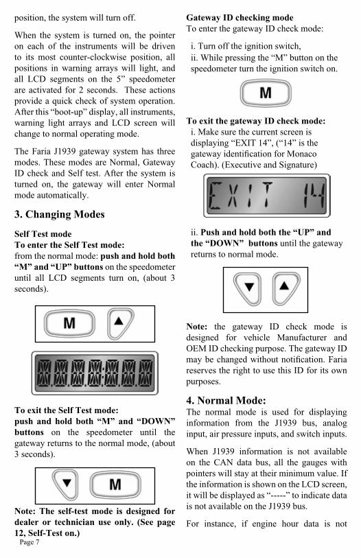
Gateway ID checking modeTo enter the gateway ID check mode:
i. Turn off the ignition switch,ii. While pressing the “M” button on the speedometer turn the ignition switch on.
To exit the gateway ID check mode:i. Make sure the current screen is displaying “EXIT 14”, (“14” is the gateway identification for Monaco Coach). (Executive and Signature)
ii. Push and hold both the “UP” and the “DOWN” buttons until the gateway returns to normal mode.
Note: the gateway ID check mode is designed for vehicle Manufacturer and OEM ID checking purpose. The gateway ID may be changed without notification. Faria reserves the right to use this ID for its own purposes.
4. Normal Mode:The normal mode is used for displaying information from the J1939 bus, analog input, air pressure inputs, and switch inputs.
When J1939 information is not available on the CAN data bus, all the gauges with pointers will stay at their minimum value. If the information is shown on the LCD screen, it will be displayed as “-----” to indicate data is not available on the J1939 bus.
For instance, if engine hour data is not
Page 7

available, it will be displayed as
“Hr - - - - -”
When any analog input and switch input is not connected, it will disable the related instrument function. For instance, when the fuel sender isn’t connected to the gateway, the fuel gauge can not reflect the fuel level in the fuel tank. When the “step out” switch isn’t connected to the gateway, a step out action cannot trigger the “step out” indicator on the light array, etc.
In normal mode, the gauges with pointers will indicate the data value on the dial, when the data is larger than the maximum value on the dial, the pointer will move to and stay at the maximum value position.
In normal mode, the LCD on the speedometer is able to display following information according to the users selection: odometer, trip odometer 1, trip odometer 2, engine hours and clock.
When the odometer is in the range of “0-99999”, the display will be “odxxxxx”,
when odometer is in the range of “100000-999999”, the display will be “oxxxxxx”.
After one million miles, the odometer will reset to zero automatically.
When the trip odometer is in the range of ”0.0-9999.9”, the display will be“Trxxxx.x”;
when the trip odometer is in the range of “10000-99999”, the display will be “Trxxxxx”;
when the trip odometer is in the range of “100000-999999”, the display will be “Txxxxxx”.
After a million miles, the trip odometer will reset to zero automatically.
When the engine hours are in the range of ”0.0-9999.9”, the display will be “Hrxxxx.x”;
When the engine hour is in the range of “”10000-99999”, the display will be “Hrxxxxx”;
when the engine hour is in the range of “100000-999999”, the display will be “Hxxxxxx”.
Page 8

IlluminationThere are 7 levels of illumination: Off, 1, 2, 3, 4, 5, and 6. The level can only be changed in the normal mode.
To turn on the illumination: Turn on the vehicle light switch.
To turn off the illumination: Turn off the light switch.
To change the back light intensity when the light switch is on: Push the “UP” button on the speedometer to increase the intensity of the instrument lighting. When the intensity reaches maximum no brighter settings can be selected.
Push the “DOWN” button on the speedometer to decrease the intensity of the instrument lighting. When the intensity reaches minimum the lights can go no lower and no less bright settings can be selected.
Note: The gateway will remember the last selected illumination level and will not need to be re-set at next power up.
Select Function:
The select function allows selection of the following LCD screens.
Odometer
TRIP 1
TRIP 2
Engine Hour
Clock
Odometer
Trip 1
Trip 2
Figure 1
Page 9

Engine Running Only Hourmeter
Clock
Returns to the Odometer.
To select a LCD function ((Odometer (-odo-), Trip odometer 1 (TRIP1), Trip odometer 2 (TRIP2), Engine Hour (ENG.HOUR), clock (CLOCK)): push the “M” button of the speedometer. Once the desired function is selected, the gateway will automatically display the function information in 2 seconds.
Note: The gateway will remember and display the last selected LCD screen at next power up.
Reset Trip Odometer 1 & 2Step 1: select TRIP 1 or TRIP 2 as described at “Select Function” section.
Step 2: once the Trip odometer mileage is displayed as “Tr xxxx.x”, push and hold the “M” button on the speedometer until the screen changes to “Tr 0.0”.
Set The Clock Step 1: select clock as described at “Select Function” section.
Step 2: Once the screen displays the time push and hold the “M” button on the speedometer until the screen blinks the time display. This will enable the clock setup.
Step 3: push the “UP” button to increase the minute “01” value.
Pushing and holding the “UP” button will make the numbers change more quickly. When the minute value reaches “59”, it will reset to zero with the next press of the “UP” button.
Step 4: push the “DOWN” button to increase the hour value.
Pushing and holding the “DOWN” button will make the numbers change more quickly.
Page 10

When the hour value reaches “23”, it will reset to zero with the next press of the “DOWN” button.
Step 5: when the clock is set, push and hold the “M” button on the speedometer until the clock stops blinking the time display. This will exit the clock setup function.
Warning MessagesDuring normal operations, 14 different warning messages can be seen on the LCD screen should a warning condition exist.
Nine (9) of the warning messages come from the J1939 bus. Four (4) of the warning messages come from the switch inputs, One (1) of the warning messages comes from the Centroid fuel sender.
The Warning messages will be accompanied by an audible alarm and a visual alarm once they appear on the LCD screen. Each of the warning messages appear for 4 seconds every minute, if all warning messages are on they each would be displayed every 52 seconds. This will ensure that each warning message gets a 4 second display on the LCD, and the user will still get 8 seconds for normal display information. All warning and normal information will repeat each minute.
The 9 warning messages on the speedometer LCD screen which come from the J1939 bus are:
1. “ENG HOT”: represents high engine coolant temperature.
2. “LoOIL P”: represents low engine oil pressure.
3. “Lo CooL”: represents low engine coolant level.
4. “Lo BAT ”: represents low battery voltage.
5. “HI BAT ”: represents high battery voltage.
6. “CHK ENG”: represents all other engine fault(s) with Amber warning lamp on.
7. “VARIOUS”: represents all other engine fault(s) with Red Stop lamp on.
8. “ ABS ”: represents there is warning message(s) from ABS controller.
Page 11
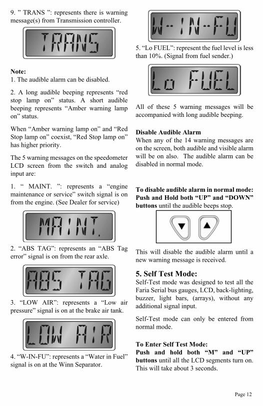
9. ” TRANS ”: represents there is warning message(s) from Transmission controller.
Note: 1. The audible alarm can be disabled.
2. A long audible beeping represents “red stop lamp on” status. A short audible beeping represents “Amber warning lamp on” status.
When “Amber warning lamp on” and “Red Stop lamp on” coexist, “Red Stop lamp on” has higher priority.
The 5 warning messages on the speedometer LCD screen from the switch and analog input are:
1. “ MAINT. ”: represents a “engine maintenance or service” switch signal is on from the engine. (See Dealer for service)
2. “ABS TAG”: represents an “ABS Tag error” signal is on from the rear axle.
3. “LOW AIR”: represents a “Low air pressure” signal is on at the brake air tank.
4. “W-IN-FU”: represents a “Water in Fuel” signal is on at the Winn Separator.
5. “Lo FUEL”: represent the fuel level is less than 10%. (Signal from fuel sender.)
All of these 5 warning messages will be accompanied with long audible beeping.
Disable Audible Alarm When any of the 14 warning messages are on the screen, both audible and visible alarm will be on also. The audible alarm can be disabled in normal mode.
To disable audible alarm in normal mode: Push and Hold both “UP” and “DOWN” buttons until the audible beeps stop.
This will disable the audible alarm until a new warning message is received.
5. Self Test Mode:Self-Test mode was designed to test all the Faria Serial bus gauges, LCD, back-lighting, buzzer, light bars, (arrays), without any additional signal input.
Self-Test mode can only be entered from normal mode.
To Enter Self Test Mode:Push and hold both “M” and “UP” buttons until all the LCD segments turn on. This will take about 3 seconds.
Page 12

To Exit Self Test Mode:Push and hold both “M” and “DOWN” buttons until the system returns to the normal mode. It will take about 3 seconds.
In Self Test mode, the gateway will test the LCD, Beep tone, Instrument lighting, and warning indicator arrays according to the following sequence:
1. All of the LCD segments will be on for 5 seconds, the warning indicator arrays will blink, and the buzzer will beep.
2. The instrument lighting will cycle 2 times from off to maximum level while the beep tone sounds. The warning arrays will continue blinking.
3. The warning light arrays will then turn on completely. Instrument lighting will be at the maximum level thereafter. And all gauges will be driven from the minimum to maximum reading then back to minimum/zero point.
4. After the gauges return to zero or minimum display value, the following will occur:
a) The Speedometer and tachometer will be driven randomly to simulate a real driving condition.b) the voltmeter will go to and stay at 14.0 volts
c) the fuel gauge will go to and stay at 75%d) the engine oil pressure gauge pointer will go to and stay at 80 PSIe) the turbo boost pointer will go to and stay at 25 PSIf) the engine coolant temperature will go to and stay at 150 Fg) the transmission oil temperature will go to and stay at 260 Fh) the front brake air pressure will go to and stay at 130 PSIi) the rear brake air pressure will go to and stay at 145 PSIj) the odometer will read the actual odometer mileage.k) Both TRIP1 and TRIP2 will read the actual trip odometers mileage.l) The engine hour will read 200,000 hour.m) The clock will read the actual time.
Page 13

Connector Pins Pin Pin Number / Function Wire ColorP1 Not Used
P2 41
34
Battery Positive (always on) (5 amp. fuse recommended)Switched Power from Ignition Switch circuitGround
(HN0516 TYPICAL)Red
PurpleBlack
P3 4 All Faria Bus Data and Instrument Power(HN0502 TYPICAL)N/A
P4 2 Not Used Not Used
P5 3 ABC
CAN Bus Signal Input – CAN-HCAN Bus Signal Input – CAN-LCAN Bus Shielding Ground
YellowGreenShield
P6 12 All1234568
Positive Switch Inputs – (>+8 V – Activate)H2O in Fuel WarningStep OutHigh BeamLeft TurnRight TurnABS TAG Error WarningInstrument Back-Lighting Switch
P7 PP Pressure Port – 0 – 1000 Kpa (Options Available) Front Air Pressure
P8 PP Pressure Port – 0 – 1000 Kpa (Options Available) Not Used
P9 PP Pressure Port – 0 – 1000 Kpa (Options Available) Rear Air Pressure
P10 12 1-6
7-1011-12
Negative Switch Inputs: < +0.8V OR <15K Ohms to Gnd – ActivatePositive Switch Inputs: > +8 V – ActivateSpecial Positive Switch Inputs: > +4 V – Activate
Not Used
Not UsedNot Used
P11 12 All
1234568
Negative Switch Inputs: < +0.8V OR < 15K Ohms to Gnd – ActivateParking BrakeGen Door OpenABS Error WarningLow Air WarningAnt UpMaintenance WarningSignature (option) (Not used for Executive)
P12 12 12
11&12
3&10
6
7
0 – 90 Ohm compatible Centroid Fuel SenderAnalog Sender Inputs: High Current (10 - 80Ma) – ConfigurableAnalog Sender Inputs: High Current (10 - 80Ma) – ConfigurableAnalog Sender Inputs: Low Current (2 - 30Ma) – ConfigurableVariable Sensitivity, High Pulse Rate, Low Noise Input: 100 – 15000 HzFixed 3.6 V Sensitivity, Low Pulse Rate, High Noise Input: 15 – 1000 Hz
PinkNot Used
Not UsedNot Used
Not Used
Not Used
P13 Not Used
Appendix 1. Installation and Wiring
Page 14

Figure 2
Page 15
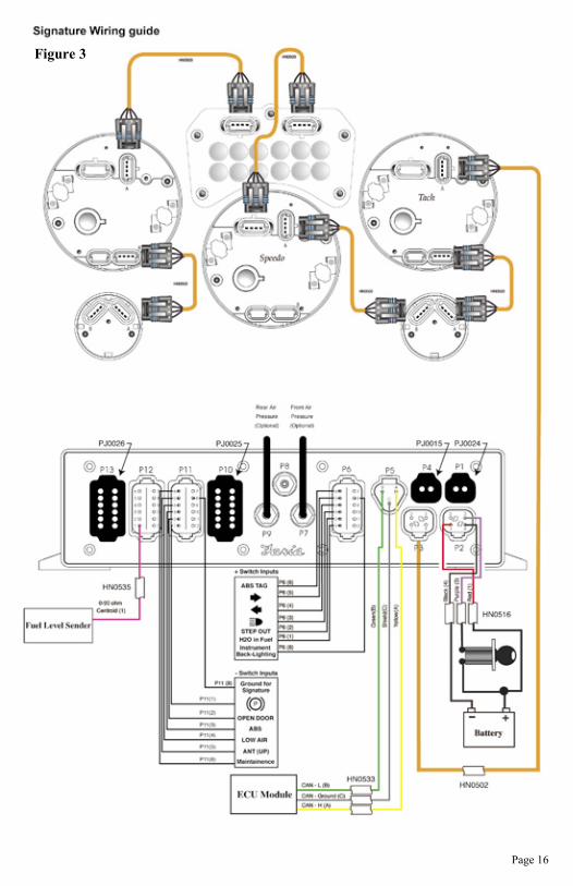
Figure 3
Page 16

Typical 2-device J1939 Network Topology
Page 17
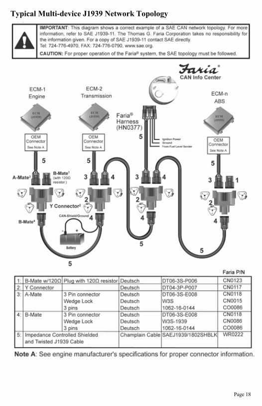
Typical Multi-device J1939 Network Topology
Page 18

Notes

Copyright 2004 by the Thomas G. Faria Corporation, Uncasville CT, all rights reserved.No part of this publication may by reproduced in any form, in an electronic retrieval system or otherwise, without the prior written permission of the company.