is the magnetosphere a lens for mhd waves?
TRANSCRIPT
GEOPHYSICAL RESEARCH LETTERS, VOL. 20, NO. 24, PAGES 2809-2812, DECEMBER 23, 1993
IS THE MAGNETOSPHERE A LENS FOR MHD WAVES?
K. Papadopoulos, A. S. Sharma and J. A. Valdivia.
University of Maryland, College Park, Maryland
Abstract. A novel viewpoint of the magnetosphere as a lens for MHD waves is presented. Using a simple model of the variation of the Allyen speed as proportional to the local magnetic field value given by the Earth's dipole field and that due to the magnetopause currents represented by a current loop, it is found that the near-Earth magnetotail, in the range 8 - 16 RE, is the focus of the magnetospheric lens. This location is found to be quite insensitive to a wide variation of parameters. By using simple diffraction theory analysis it is found that the focal region extends about 1 RE about the neutral sheet in the north-south plane and 0.2 - 0.5 RE along the Sun-Earth line. Compressive MHD waves carried by the solar wind or created by the interaction of the wind with the magnetopause can be amplified by a factor of about 100 in the focal region and this has potentially important implications to substorm activity.
Introduction
The magnetic field and plasma configuration of the mag- netosphere can be viewed as an optical system through which MHD waves propagate. These waves can be focused or defo- eused depending on the variation of the refractive index which is inversely proportional to the Alfven speed v^ = B/ where B is the magnetic field and p the mass densiiy. It will be shown below that when the interplanetary magnetic field (IMF) convected to the magnetosphere by the solar wind has a southward component, the configuration can act as an optical system that focuses MHD waves transported by the solar wind, as well as the ones generated at upstream dis- continuities. This lensing action can then focus the MHD waves by guiding their Poynting flux towards the near-Earth magnetotail leading to local enhancement of the wave energy density. As discussed by Lui et al. [1992] such wave en- ergy enhancements have been observed at about 10 RE in the magnetotail and can have significant implications for the dynamics of substorms.
The objective of this letter is to present the basic physics underlying the idea of the magnetosphere as a lens by using a simplified analysis that relies on conventional techniques of optics. More detailed analysis and modeling using MHD codes is currenfiy under way and will appear at a later time. The next section presents the basic optical properties of wave propagation in the combined magnetic fields of the Earth's dipole and the magnetopause currents. By utilizing a simple model of the magnetic field as a superposition of the dipole field and that of a coil representing the magnetopause currents, the focal distance, the beam width and the Raleigh length are computed. The observational evidence, model pitfalls and limitations, and implications for magnetospheric
Copyright 1993 by the American Geophysical Union.
Paper number 93GL03011 0094-8534/93/93GL-03011 $03.00
processes such as the substorms are presented in the final section.
Focusing of MHD Waves by the Magnetosphere
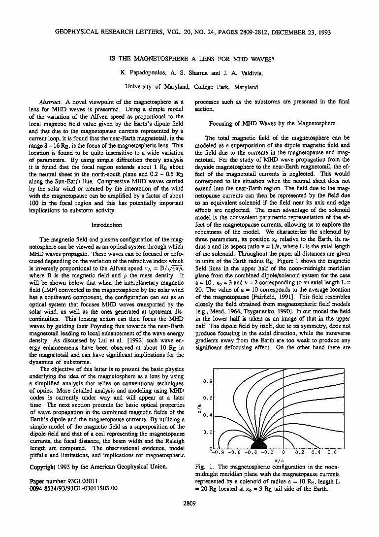
The total magnetic field of the magnetosphere can be modeled as a superposition of the dipole magnetic field and the field due to the currents in the magnetopause and mag- netotail. For the study of MHD wave propagation from the dayside magnetosphere to the near-Earth magnetotail, the ef- fect of the magnetotail currents is neglected. This would correspond to the situation when the neutral sheet does not extend into the near-Earth region. The field due to the mag- netopause currents can then be represented by the field due to an equivalent solenoid if the field near its axis and edge effects are neglected. The main advantage of the solenoid model is the convenient parametric representation of the ef- fect of the magnetopause currents, allowing us to explore the robustness of the model. We characterize the solenoid by three parameters, its position Xo relative to the Earth, its ra- dius a and its aspect ratio v = L/a, where L is the axial length of the solenoid. Throughout the paper all distances are given in units of the Earth radius RE. Figure 1 shows the magnetic field lines in the upper half of the noon-midnight meridian plane from the combined dipole/solenoid system for the case a = 10, Xo = 3 and v = 2 corresponding to an axial length L = 20. The value of a = 10 corresponds to the average location of the magnetopause [Fairfield, 1991]. This field resembles closely the field obtained from magnetospheric field models [e.g., Mead, 1964; Tsyganenko, 1990]. In our model the field in the lower half is taken as an image of that in the upper half. The dipole field by itself, due to its symmetry, does not produce focusing in the axial direction, while the transverse gradients away from the Earth are too weak to produce any significant defocusing effect. On the other hand there are
0.8
0.6
0.4
0.2
o -0.8 -0.6 -0.4 -0.2 o 0.2 0.4 0.6
x/a
Fig. 1. The magnetospheric configuration in the noon- midnight meridian plane with the magnetopause currents represented by a solenoid of radius a = 10 R•., length L = 20 R•. located at Xo = 3 R•. tail side of the Earth.
2809

2810 Papadopoulos et al.' Magnetosphere as a Lens
significant gradients related to the field of the magnetopause currents, represented by a solenoid in this model, which can lead to focusing. The important parameter controlling the focusing properties is the variation of the Alfven speed. In view of the dependence of the Alfven speed on the square root of the plasma density, compared to the direct depen- dence on the magnetic field, we neglect the density variation and assume that the gradients of the Alfven speed arise from magnetic field gradients alone. This is motivated in part by the lack of observed density profiles or models of the inner magnetosphere at 10- 15 Rs. The index of refraction can then be written as
1 4x'nMc2 1 rl- + B 2 •" B
The magnetic field B is a function of the distance x with respect to the Earth along the Sun-Earth line, the distance z from the x axis along the south-north direction, and the aspect ratio v = L/a. From the magnetic field of a solenoid, the spatial variation of the refractive index in the Sun-Earth meridian plane can be computed by using the expressions of B for a solenoid. A numerical fit of the contours yields, for small x,
(1)
where f(v) is a function of the aspect ratio alone. A simple ex- pression for f(v) is obtained by considering the fact that r/-• r/0 for large v and this yields f(v) = ezp(0.07- 1.05v) m exp(-v). The magnetosphere is then represented by an equivalent optical system with a refractive index V(z, v) and the propagation of the incident MHD waves can be analyzed using standard optical techniques. A convenient method is the matrix propagator technique [Yariv, 1989, Chap. 6] in which, in the paraxial approximation, the propagation of a ray at position z with slope z' (-- dz/dx) to (Zl, z•) is given by
Z• = M zt (2)
The matrix M propagates the ray from one point to the next and is a function of the properties of the medium. For the solenoid model in which the dependence of the refractive index on z is quadratic as given by (1), M is given by [Yariv, 1989, p. 113]
-0 sin(OAx)
where
}- sin(OAx) ] , cos(OAx) (3)
0- v/2f(v) a
A ray propagates through the solenoid for a distance Ax = L, emerges at x = L/2 and then propagates through a medium of constant refractive index. The action of the dipole field is represented by two adjacent refracting surfaces with opposite curvatures but the same radius of curvature, and does not yield a focusing effect. The rays emerging from the solenoid propagate a distance d = x -- L/2 without any change in their slope and is represented by the propagator
0 Z ' (4)
The final effect on the MHD waves is given by
(5)
which is the product of the lensing effect of the solenoid represented by Ms and the subsequent rectilinear propagation in a medium of constant refractive index % for the distance (x- L/2) represented by Ml(x -- L/2).
The focal length of the optical system representing the magnetosphere can be computed from (2) -- (5) for a ray incident parallel to the x axis. The focal length f is the distance along the x-axis from the center of the lens (x=0) to the point where the ray intersects the axis, i.e. z l = 0 at x = f. Using (1) -- (5) we have computed the focal length as a function of the aspect ratio v, for values of the solenoid radius (magnetopause location) a between 7 and 12 R•. and the results are shown in Figure 2. The most prominent aspect of Figure 2, is the relative invariance of the focal length f for a variation of the magnetopause position in the range from 7 to 12 R•. and values of the aspect ratio v > 0.3. The magnetic field configuration for v < 0.3 does not correspond to that of the magnetosphere as the tail fields flare out close to the Earth (at about 3 R•. for a = 10 R•.) and thus is not relevant. The
30
25
.020
• 15
oø10
a=12
5 a=7
0 0.25 0.5 0.75 1 1.25 1 • 1.'7'5' 2 v=L/a
Fig. 2. The focal length (in RE) as a function of the aspect ratio v for the magnetopause radius a = 7 (bottom curve), 8, 9, 10, 11 and 12 (top curve), and Xo = 0. Since Xo is only a linear displacement, the focal length f becomes f + Xo for nonzero Xo. The focal length is insensitive to changes in v and a over a wide range of values.

Papadopoulos et al.: Magnetosphere as a Lens 2811
value of the focal length f from Figure 2 is between 8 and 14 R•.. The actual location of the focus is f + Xo, Xo being the relative distance between the solenoid and the Earth, and
since Xo < 3, the expected focal position will still be 8 - 17 R•.. The focal length can also be estimated by considering the magnetic field lines to coincide with the refracting surfaces of an equivalent lens. Using the magnetic field model of Mead [ 1964] the radii of curvature of these surfaces can be obtained and this yields focal lengths of about 10 R•., in agreement with the more detailed computations presented here.
The analogy between the magnetosphere and optical sys- tems can be carried further to estimate the spatial properties of the focused wave beam such as width, divergence and shape for diffraction limited propagation. These quantities allow us to estimate the amplification of the wave energy density and the dimensions of the focusing area and can be obtained from the Gaussian beam analysis given below.
The solution of the wave equation for a Gaussian beam under paraxial approximation is [Yariv, 1989, p. 118]
•b • exp{-i k
p(x) + 2q(x) z2 where co is the angular frequency, k = %co/c and p(x) is a phase term. The complex function q(x) is related to the width of the beam w(x) at the location x in the perpendicular plane by
1 1 2i
q(x) R(x) kw2(x) '
where R is the radius of curvature of the beam. The profile of the beam along x is characterized by the Raleigh length ro, defined as w2(x) 2 I + (x- xo - f) /r; In terms -- Wmi n ß
of the matrix propagators q(x) is given by
qoM11 q- M12 q(x) = qoM21 + M22'
where qo - ikWo2/2, Wo = a being the initial beam width
0.06
BEAM WIDTH
0.05
00.04
0.03
-,-I
• 0.02
0.01
{ a=7 v=2 }
{a=12, v=0.5}
15 20 25 30 35 40
kR E
Fig. 3. Beam width at the focusing region as a function of k = rioco/c, for different values of a and v: {v = 0. 5, a = 12} (bottom curve), {v = 2, a = 12}, {v = 0.5, a = 7} and {v = 2, a = 7 } (top curve). Again the insensitivity on the parameters is striking.
RALEIGH LENGTH
0.8
"q 0.4
0.2
v=2.0
v=1.5
v=l.0
v=0.5
15 20 25 30 35 40 45 50
kR E
Fig. 4. Raleigh length (in R}•) as a function of k = rioco/c, for different values of a in the range 7 - 12 R•. and v = L/a in the range 0.5 - 2. Each curve corresponds to the specified value of v and all the values of a, and thus a has almost no effect on the Raleigh length.
and Mij are the elements of the matrix M(x) given by (5). For our case we assume that the incident beam corresponds to a plane wave with infinite radius of curvature. We obtain w(x) from the imaginary part of 1/q(x) and compute the beam width at the focal length, where it is a minimum (which is also where 1/R(x)=0). The normalized transverse beam width at the focus Wmin/a is shown in Figure 3 as a function of the wavelength kRE of the incident Alfven waves. Under typical conditions kRE __m 10 - 20 giving a width Wmin in the range 0.02 - 0.04 Wo, which for Worn 10 correspond to 0.5 - 1.0 RE. The Raleigh length ro represent the axial width of the beam in the focal region and is shown in Figure 4 for the same range of parameters, and has typical values in the range 0.2 - 0.5 RE. These values are consistent with simple diffraction theory estimates. The enhancement of the MHD energy flux can be estimated by assuming comparable inflow and outflow speeds. It will then be given by
where A is the width about the North-South plane over which focusing occurs. Taking A/a m 0.2, we find enhancement of the wave energy due to focusing of the order of 10 2 .
Summary and Conclusions
We have presented an admittedly simplified analysis of the Earth's magnetosphere as a lens for MHD waves. The analysis shows that the near-Earth magnetotail location, in the range of 8 - 15 RE, is indeed a special location representing the natural focal point of the magnetoSphere. The width of the focus is about 1 R•. on each side of the equatorial plane and the activity extends about 0.2 - 0.5 RE about the focus along the Sun-Earth line, leading to enhancements of about 100 in the fluctuation energy density of the MHD waves. The most important aspect of our analysis is the "robustness" of the focal location and its characteristics over
a broad range of parameter variations. It is this insensitivity of the main result to details that makes the lensing concept

2812 Papadopoulos et al.' Magnetosphere as a Lens
attractive. In addition to the parametric studies presented here, we have varied a number of other parameters, involving the dipole field and the solenoid with little influence on the final results. While we expect that detailed models 'including density variations and three dimensional aspects will reveal important aspects, we do not expect that the focal range will change significantly.
On the observational side we should note that enhanced
MHD activity by almost two orders of magnitude in the near tail was observed by AMPTE/CCE [Lopez et al., 1990; Lui et al., 1992]. Furthermore, focusing of the Poynting flux in the region of 8 - 12 RE was found in three dimensional MHD simulations of substorms (J. Lyon, private communication, 1993).
In concluding we should emphasize that a key objective of this letter is to provide an alternative viewpoint of the magnetosphere and to induce the experimental and modeling community to examine their data and simulation models from the viewpoint of the Earth's and other magnetospheres as lenses of incident MHD waves.
Acknowledgments. We thank J. Lyon for tracing the Poynting flux in his 3-D global MHD simulations. Many fruitful discussions with C. Goodrich, R. E. Lopez and R. Sagdeev are gratefully acknowledged. This work was sup- ported by NASA/ISTP grant NAG 5-1101.
References
Fairfield, D. H., Solar wind control of the size and shape of the magnetosphere, J. Geomag. Geoelct., 43, Suppl., 117, 1991.
Lopez, R. E., H. Luhr, B. J. Anderson and P. Newell, Multi- point observations of a small substorm, J. Geophys. Res., 95, 18897, 1990.
Lui, A. T. Y., R. E. Lopez, B. J. Anderson, K. Takahashi, L. J. Zanetti, R. W. McEntire, T. A. Potemra, D. M. Klurnpar, E. M. Greene and R. Strangeway, Current disruptions in the near-Earth neutral sheet region, J. GeophyS. Res., 97, 1461, 1992.
Mead, G. D., Deformation of the geomagnetic field by the solar wind, J. Geophys. Res., 83, 1181, 1964.
Yariv, A., Quantum Electronics, Wiley, New York, 1989. Tsyganenko, N. A., Quantitative models of the magneto-
spheric magnetic field: Methods and results, Space Sci. Rev, 54, 75, 1990.
K. Papadopoulos, A. S. Sharma, J. A. Valdivia, Depart- ments of Physics and Astronomy, University of Maryland, College Park, Maryland 20742.
(Received: August 5, 1993; revised: October 4, 1993; accepted: October 20, 1993)