is that splice really good enough? improving fiber optic...
TRANSCRIPT

Is That Splice Really Good Enough?
Improving Fiber Optic Splice Loss Improving Fiber Optic Splice Loss MeasurementMeasurement
Presented on Behalf of the Project Members
by Peter Arrowsmith
Board Assembly TIG
Fiber Optic Splice Improvement Fiber Optic Splice Improvement ProjectProject

3Connect With and Strengthen your Supply Chain Connect With and Strengthen your Supply Chain
Acknowledgements
• 3SAE– Jared Meitzler
• Aurora:– Larry Wesson
• Celestica:– Peter Arrowsmith– Rob Suurmann
• Jabil– Marty Rodriguez
• NEMI:– David Godlewski
• Nortel Networks– Denis Gignac
• Sanmina-SCI:– Eamon O’Keeffe– Salil Pradhan
• Solectron, iPhotonics:– Jennifer Curran– Jennet Johnson
• Sumitomo Electric:– Don Gross– Tom Watanabe
• Vytran:– Eric Mies

4Connect With and Strengthen your Supply Chain Connect With and Strengthen your Supply Chain
Improved Fiber Splicing Project
• Project Objective (from Statement of Work):– To develop and promote industry-wide test methods and splice
quality criteria that will allow for systematic investigation of variability, comparison of equipment, improved yield and lower costs
• Project Benefits:– Promote the use of common metrics and measurement methods – Identify the critical cause(s) of splice variation for future yield
improvement– Submit methods and guidelines for incorporation into OE standards,
e.g. IPC-STD-040.
• Meeting Objectives:– Share technical results– Promote awareness of project activities– Attract optoelectronics OEM participation
5Connect With and Strengthen your Supply Chain Connect With and Strengthen your Supply Chain
Areas of Interest & Priorities
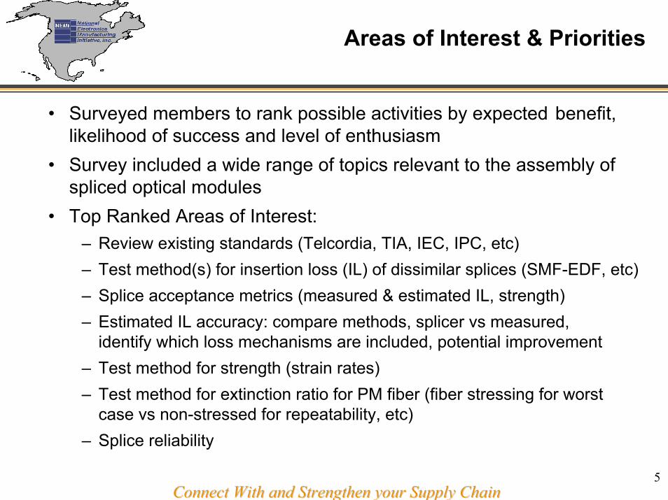
• Surveyed members to rank possible activities by expected benefit, likelihood of success and level of enthusiasm
• Survey included a wide range of topics relevant to the assembly of spliced optical modules
• Top Ranked Areas of Interest:– Review existing standards (Telcordia, TIA, IEC, IPC, etc) – Test method(s) for insertion loss (IL) of dissimilar splices (SMF-EDF, etc)– Splice acceptance metrics (measured & estimated IL, strength)– Estimated IL accuracy: compare methods, splicer vs measured,
identify which loss mechanisms are included, potential improvement– Test method for strength (strain rates)– Test method for extinction ratio for PM fiber (fiber stressing for worst
case vs non-stressed for repeatability, etc) – Splice reliability

6Connect With and Strengthen your Supply Chain Connect With and Strengthen your Supply Chain
Current & Planned Activities
• Reviewing relevant standards from Telcordia, TIA, IEC, JIS• Identify gaps relative to product (plant) splicing (loss <0.05 dB)• Participants measuring SMF28-SMF28 loss using current test methods• Compare in-line, unterminated fiber (cut-back/BFA) and OTDR loss
measurement methods• Developed Gage R&R method to assess measurement error• Extend GR&R to SMF-EDF splicing (common batch of Er)• Identify causes of measurement variation• Work with IPC, TIA to improve existing & develop new standards• Follow-on activities are decided by members• Weekly conference calls• Last face-to-face meeting: OFC Atlanta, March 27• Project completion 3-4Q 2003, depending on scope & interest

7Connect With and Strengthen your Supply Chain Connect With and Strengthen your Supply Chain
Status of Project and Presentation Synopsis
1. Standards review. Request to IEC to 80% complete distribute IEC 61073-3/1073-3 (splices) and 1073-1 to group
2. SMF-SMF gage R&R comparison of member’s Completesplice loss test methods
3. Correlation of estimated vs. measured loss 80% complete 4. Loss estimator accuracy metrics, confidence limits 50% complete5. Statistical comparison of actual loss distributions 50% complete
based on 1000 splice data sets, 6. Distribution of EDF to group Complete
(single fiber batch from Sumitomo)7. SMF-EDF splice loss DOE 20% complete8. Draft splice loss standard for SMF-EDF Planned

8Connect With and Strengthen your Supply Chain Connect With and Strengthen your Supply Chain
1. Standards Review
Goals• Improve knowledge of existing specifications from Standards bodies• Review all relevant specifications to see if product-level splicing requirements
are addressed, vs. field/network splicing• Compare standards to identify gaps, conflicts and overlaps
Actions Taken• Identified the following bodies:
– ITU-T, ETSI, JSA, Telcordia, TIA/EIA, IEC, BT, IPC & DOD Mil Stds• Members split up workload and concurrently reviewed standards on-hand• The following standards bodies have most relevant specifications:
– Telcordia (TRs, GRs…), TIA (FOTPs…), IEC• Approached IPC-PMA, Telcordia, TIA and IEC representatives to request
additional standards, copies for use within project, and to develop partnerships• TIA and IPC are enthusiastic to work with NEMI project on improved or new
splice standardsNote: Project members would like to thank TIA for providing CD copies of the TIA standards requested.

9Connect With and Strengthen your Supply Chain Connect With and Strengthen your Supply Chain
Standards Review: Splicer & Splice Acceptance

10Connect With and Strengthen your Supply Chain Connect With and Strengthen your Supply Chain
Standards Review: Splice Loss Test

11Connect With and Strengthen your Supply Chain Connect With and Strengthen your Supply Chain
Standards Review – Key Findings
• Many of the standards that cover splicing are 6 or more years old and therefore do not cover newer fibers (80/165 µm, NZ-DS, LEAF) or fiber combinations such as dissimilar splicing (EDF-SMF, etc).
• For standards purposes, it is not clear whether a splice should be considered a fiber or a passive component
• Most of the standards do not address splicing for optical module assembly• Most specs consider splice losses of 0.1-0.4 dB to be acceptable• Splice loss test requirements (source stability, measurement accuracy and
repeatability, etc) are generally inadequate for low loss product splicing• For today’s products with SMF-SMF, low loss splices of 0.0-0.05 dB are routine,
requiring measurement repeatability of ±0.005 dB (10% of the range)• A source stability of <0.01 dB (Telcordia GR-765, 1095) is barely adequate • Practical information on test set-ups and methods are generally omitted • TIA 455-34A comes closest to meeting our needs for a loss measurement
method

12Connect With and Strengthen your Supply Chain Connect With and Strengthen your Supply Chain
2. Member Splice Loss Test Methods
IsolatorVOA
Source Detector
FiberLoop
FiberLoop
Source DetectorIsolator Splice
FiberLoop
NewFiber
Source Detector
Isolator Splice
Integrating Sphere
BFA
1. Stability: In-Line or BFA Methods (linearity requires VOA)
2. Gage R&R: In-Line Loss Method
3. Gage R&R: BFA Loss Method
4. Gage R&R: OTDR Loss Method
Reel of Identical Fiber
Reel of Identical Fiber
Splice
DemountableConnector

13Connect With and Strengthen your Supply Chain Connect With and Strengthen your Supply Chain
Gage R&R Test Method and Data Collection
•Members submitted Gage R&R data using the In-line, BFA and OTDR methods•Three loss ranges (0-0.05, 0.05-0.1, 0.1-0.15 dB), each measured by three operators •Splicing and test equipment varied between members. Also variations in test setup, e.g. use of isolators, mode filters (fiber loops), coupling to detector & methodology•Measurement repeatability as a percentage of the range is acceptable (≤10%), marginal (10-30%) or unacceptable (>30%) •All used the same Gage R&R spreadsheet calculator•Parameters recorded and used:
•Measured loss (assumed to be actual loss)•Splicer estimated loss•Periodic source power & detector reading for stability monitoring
(except OTDR method)•Recorded only: cleave angles, splicer condition (arc time, power), env. conditions

14Connect With and Strengthen your Supply Chain Connect With and Strengthen your Supply Chain
Splice Measurement RepeatabilityGage R&R Study: Data Sets

15Connect With and Strengthen your Supply Chain Connect With and Strengthen your Supply Chain
Splice Measurement Repeatability:Gage R&R Stability
• Three stability runs per measurement system (except for one BFA)• Source stability is not relevant for OTDR (µs to ns pulse)• Time interval over which stability was monitored was the same as the
splice process & measurement period • The maximum drift deviation of the 3 runs was used to define the stability
error
• Laser Source Stability
-0.0005
0.0000
0.0005
0.0010
0.0015
0.0020
0 5 10 15 20 25 30
Time (minutes)
Pow
er D
rift (
dB)
Run 1Run 2Run 3

16Connect With and Strengthen your Supply Chain Connect With and Strengthen your Supply Chain
Splice Measurement RepeatabilityGage R&R Study – Results
17Connect With and Strengthen your Supply Chain Connect With and Strengthen your Supply Chain
Splice Measurement RepeatabilityGage R&R Study – Conclusions
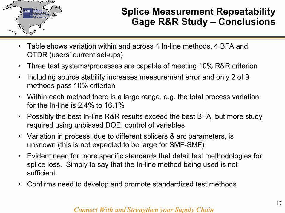
• Table shows variation within and across 4 In-line methods, 4 BFA and OTDR (users’ current set-ups)
• Three test systems/processes are capable of meeting 10% R&R criterion• Including source stability increases measurement error and only 2 of 9
methods pass 10% criterion• Within each method there is a large range, e.g. the total process variation
for the In-line is 2.4% to 16.1%• Possibly the best In-line R&R results exceed the best BFA, but more study
required using unbiased DOE, control of variables• Variation in process, due to different splicers & arc parameters, is
unknown (this is not expected to be large for SMF-SMF)• Evident need for more specific standards that detail test methodologies for
splice loss. Simply to say that the In-line method being used is not sufficient.
• Confirms need to develop and promote standardized test methods
18Connect With and Strengthen your Supply Chain Connect With and Strengthen your Supply Chain
3. Splicer Based Loss Estimation
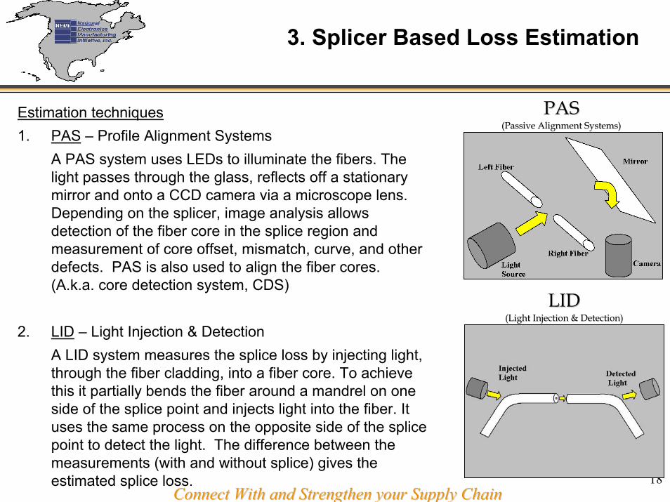
PAS PAS (Passive Alignment Systems) (Passi
Estimation techniques1. PAS – Profile Alignment Systems
A PAS system uses LEDs to illuminate the fibers. The light passes through the glass, reflects off a stationary mirror and onto a CCD camera via a microscope lens.Depending on the splicer, image analysis allows detection of the fiber core in the splice region and measurement of core offset, mismatch, curve, and other defects. PAS is also used to align the fiber cores. (A.k.a. core detection system, CDS)
2. LID – Light Injection & DetectionA LID system measures the splice loss by injecting light, through the fiber cladding, into a fiber core. To achieve this it partially bends the fiber around a mandrel on one side of the splice point and injects light into the fiber. It uses the same process on the opposite side of the splice point to detect the light. The difference between the measurements (with and without splice) gives the estimated splice loss.
ve Alignment Systems)
LIDLID(Light Injection & Detection) (Light Injection & Detection)

19Connect With and Strengthen your Supply Chain Connect With and Strengthen your Supply Chain
Correlation of Measured vs. Estimated Loss
• Measured vs Estimated Loss• Low loss splicing for module assembly requires more accurate loss estimation • Active splicing is used to ensure accuracy, but requires optical I/O access• What are the failure modes for the outliers?• Can the estimation be improved (software/hardware)?
• Figure opposite shows Measured vs Estimated insertion loss for SMF-SMF splices on different‘PAS’ style splicers

20Connect With and Strengthen your Supply Chain Connect With and Strengthen your Supply Chain
Measured vs Estimated Loss:Low Loss Range
• Actual splice loss measurement often not possible for component pig-tail splicing
• LID unsuitable for some jackets, diam. >250 µm
• Product splice yield may depend on estimated loss
• Accuracy of estimator insufficient for low loss splicing <0.05 dB, even for SMF28-SMF26
• Compare estimators for different splicers, based on metrics, e.g. deltas & confidence limits
False rejects: impact yield, False rejects: impact yield, unnecessary reworkunnecessary rework
False accepts:False accepts:system test failsystem test fail

21Connect With and Strengthen your Supply Chain Connect With and Strengthen your Supply Chain
4. Splice Loss Delta Results –Comparison of Estimator Error Using Cpk

22Connect With and Strengthen your Supply Chain Connect With and Strengthen your Supply Chain
4. Splice Loss Metrics:Simulated Est. vs Actual Loss Distributions

23Connect With and Strengthen your Supply Chain Connect With and Strengthen your Supply Chain
Statistical Metrics Comparison:TIA 455-B Methods & Cpk (Simulated Data)

24Connect With and Strengthen your Supply Chain Connect With and Strengthen your Supply Chain
Splice Loss Estimation – Conclusions
• Most users for this investigation used different splicers with PAS estimators
• Accuracy of estimator insufficient for low loss splicing <0.05 dB, even for SMF-SMF
• Compared statistical metrics from TIA 455-B with Cpk• Cpk shows good discrimination for best case (low scatter, bias or slope)• Control limits for Cpk are arbitrary, hence only relative Cpk can be
compared• The current PAS estimators would fail (Cpk<1.5) with typical process
control limits, e.g. 20% of the range, or ±0.01 dB for the low loss range• Different estimators may have poor response to attenuation splices,
when “defects”, such as mode offset, are introduced

25Connect With and Strengthen your Supply Chain Connect With and Strengthen your Supply Chain
Possible Future Activities
As a follow-on to the Gage R&R study, we will run refined survey toassess the benefit to, and enthusiasm of, members to:• Quantify splice estimator accuracy, based on confidence limits • Splice SMF at limits of MFD, core concentricity, eccentricity and
batch-to-batch variation• Investigate sources of loss variation (prep, splice, test, processes &
equipment) • Extend Gage R&R to SMF-EDF splicing… currently in-progress• Form sub-project to develop low loss test standard for dissimilar fiber
splicing with IPC/TIA• Develop Design Guide for splice losses (loss budget predictor)• Splice strength testing• PM splicing, loss, etc

26Connect With and Strengthen your Supply Chain Connect With and Strengthen your Supply Chain
New Participants
• Project will accept new members by 3/4 majority vote• Welcome additional members, particularly OEMs & equipment
suppliers• Contacts:
Chair: Peter Arrowsmith, [email protected]: Eric Mies, [email protected]: Rob Suurmann, [email protected] NEMI: David Godlewski, [email protected]
Thank YouThank YouFiber Splice Improvement ProjectFiber Splice Improvement Project