is-gps-705b, 21 sep 2011 - us coast guard navigation center
TRANSCRIPT


i IS-GPS-705B
21 Sep 2011
REVISION RECORD
LTR DESCRIPTION DATE APPROVED
NC Initial Release 24 Nov 03 24 Nov 03
A Incorporates GPSIIIA changes 8 Jun 2010 8 Jun 2010
N/A SE&I Tech Pubs 29 July 2010
A IRN-IS-705A-001 - RFC 00016B - Pseudorandom Noise
(PRN) Expansion
21 Sep 2011
IRN-IS-705A-002 - RFC 00077B - Public Document
Management (GPS III terminology and Space Service
Volume (SSV) group delay)
IRN-IS-705A-003 - RFC 00086 - User Range Accuracy
(URA) Definition
IRN-IS-705A-004 - RFC 00091A - Civil Navigation (CNAV)
Durations
IRN-IS-705A-005 - RFC 00093 - Technical Note 36
IRN-IS-705A-006 - RFC 00097 - Pseudorange Parameters
B Incorporation of IRN-IS-705A-001 through IRN-IS-705A-006 21 Sep 2011
ii IS-GPS-705B
21 Sep 2011
Table of Contents
1. INTRODUCTION ................................................................................................................................................... 1
1.1 Scope. .................................................................................................................................................................. 1
1.2 IS Approval and Changes. ................................................................................................................................... 1
2. APPLICABLE DOCUMENTS............................................................................................................................... 1
2.1 Government Documents. ..................................................................................................................................... 1
2.2 Non-Government Documents. ............................................................................................................................. 2
3. REQUIREMENTS .................................................................................................................................................. 3
3.1 Interface Definition. ............................................................................................................................................. 3
3.2 Interface Identification. ........................................................................................................................................ 4
3.2.1 Ranging Codes. ............................................................................................................................................. 4
3.2.1.1 L5-Codes. .............................................................................................................................................. 4
3.2.1.2 Non-Standard Codes. ............................................................................................................................. 4
3.2.2 NAV Data. .................................................................................................................................................... 4
3.2.3 L5 Signal Structure. ...................................................................................................................................... 8
3.3 Interface Criteria. ................................................................................................................................................. 8
3.3.1 Composite Signal. ......................................................................................................................................... 8
3.3.1.1 Frequency Plan. ..................................................................................................................................... 8
3.3.1.2 Correlation Loss. .................................................................................................................................... 8
3.3.1.3 Carrier Phase Noise. .............................................................................................................................. 8
3.3.1.4 Spurious Transmissions. ........................................................................................................................ 8
3.3.1.5 Phase Quadrature. .................................................................................................................................. 9
3.3.1.6 Signal Power Levels. ............................................................................................................................. 9
3.3.1.6.1 Space Service Volume (SSV) Received Signal Power Levels...................................................... 10
3.3.1.7 Equipment Group Delay. ..................................................................................................................... 11
3.3.1.7.1 Group Delay Uncertainty. ............................................................................................................. 11
3.3.1.7.2 Group Delay Differential. ............................................................................................................. 11
3.3.1.7.3 Space Service Volume Group Delay Differential. ........................................................................ 11
3.3.1.8 Signal Coherence. ................................................................................................................................ 11
iii IS-GPS-705B
21 Sep 2011
3.3.1.9 Signal Polarization. .............................................................................................................................. 11
3.3.2 PRN Code Characteristics. ......................................................................................................................... 12
3.3.2.1 Code Structure. .................................................................................................................................... 12
3.3.2.2 Code Generation. ................................................................................................................................. 13
3.3.2.3 Q5 Synchronization Sequence. ............................................................................................................ 16
3.3.3 Navigation Data. ......................................................................................................................................... 17
3.3.3.1 Navigation Data Modulation................................................................................................................ 17
3.3.3.1.1 Forward Error Correction ............................................................................................................. 17
3.3.3.1.2 Neuman-Hofman Code. ................................................................................................................ 19
3.3.4 GPS Time and SV Z-Count. ....................................................................................................................... 19
4. NOT APPLICABLE .............................................................................................................................................. 21
5. NOT APPLICABLE .............................................................................................................................................. 22
6. NOTES ................................................................................................................................................................... 23
6.1 Acronyms........................................................................................................................................................... 23
6.2 Definitions. ........................................................................................................................................................ 26
6.2.1 User Range Accuracy. ................................................................................................................................ 26
6.2.2 SV Block Definitions. ................................................................................................................................. 26
6.2.2.1 Developmental SVs. ............................................................................................................................ 26
6.2.2.2 Operational SVs. .................................................................................................................................. 26
6.2.2.2.1 Block IIA SVs. .............................................................................................................................. 26
6.2.2.2.2 Block IIR SVs. .............................................................................................................................. 26
6.2.2.2.3 Block IIR-M SVs. ......................................................................................................................... 26
6.2.2.2.4 Block IIF SVs. .............................................................................................................................. 26
6.2.2.2.5 GPS III SVs. ................................................................................................................................. 26
6.2.3 Operational Interval Definitions. ................................................................................................................ 26
6.2.4 GPS Week Number. .................................................................................................................................... 26
6.3 Supporting Material. .......................................................................................................................................... 26
6.3.1 L5 Received Signals. .................................................................................................................................. 26
6.3.2 Integrated Phase Noise Characteristics. ...................................................................................................... 26
iv IS-GPS-705B
21 Sep 2011
6.3.3 Ellipticity Characteristics. ........................................................................................................................... 27
6.3.4 Additional PRN Sequences. ........................................................................................................................ 27
6.4 Operational Protocols ........................................................................................................................................ 32
10. APPENDIX I. LETTERS OF EXCEPTION.................................................................................................... 33
20. APPENDIX II. GPS NAVIGATION DATA STRUCTURE FOR L5 CNAV DATA, D5(t) ......................... 38
20.1 Scope. .............................................................................................................................................................. 38
20.2 Applicable Documents. .................................................................................................................................... 38
20.2.1 Government Documents. .......................................................................................................................... 38
20.2.2 Non-Government Documents. .................................................................................................................. 38
20.3 Requirements. .................................................................................................................................................. 38
20.3.1 Data Characteristics. ................................................................................................................................. 38
20.3.2 Message Structure. .................................................................................................................................... 38
20.3.3 Message Content. ...................................................................................................................................... 39
20.3.3.1 Message Types 10 and 11 Ephemeris and Health Parameters. .......................................................... 52
20.3.3.1.1 Message Types 10 and 11 Ephemeris and Health Parameter Content. ....................................... 52
20.3.3.1.2 Message Types 10 and 11 Ephemeris Parameter Characteristics. .............................................. 57
20.3.3.1.3 User Algorithm for Determination of SV Position. .................................................................... 57
20.3.3.2 Message Types 30 through 37 SV Clock Correction Parameters. ..................................................... 61
20.3.3.2.1 Message Types 30 through 37 SV Clock Correction Parameter Content. .................................. 61
20.3.3.2.2 Clock Parameter Characteristics. ................................................................................................ 62
20.3.3.2.3 User Algorithms for SV Clock Correction Data. ........................................................................ 62
20.3.3.2.4 Non-Elevation-Dependent (NED) Accuracy Estimates. ............................................................. 63
20.3.3.3 Message Type 30 Ionospheric and Group Delay Correction Parameters. .......................................... 67
20.3.3.3.1 Message Type 30 Ionospheric and Group Delay Correction Parameter Content. ....................... 67
20.3.3.4 Message Types 31, 12 and 37 Almanac Parameters. ......................................................................... 72
20.3.3.4.1 Almanac Reference Week. .......................................................................................................... 72
20.3.3.4.2 Almanac Reference Time. .......................................................................................................... 72
20.3.3.4.3 SV PRN Number. ....................................................................................................................... 72
20.3.3.4.4 Signal Health (L1/L2/L5). .......................................................................................................... 72
v IS-GPS-705B
21 Sep 2011
20.3.3.4.5 Midi Almanac Parameter Content. .............................................................................................. 72
20.3.3.4.6 Reduced Almanac Parameter Content. ....................................................................................... 74
20.3.3.5 Message Type 32 Earth Orientation Parameters (EOP). .................................................................... 76
20.3.3.5.1 EOP Content. .............................................................................................................................. 76
20.3.3.6 Message Type 33 Coordinated Universal Time (UTC) Parameters. .................................................. 78
20.3.3.6.1 UTC Parameter Content. ............................................................................................................. 78
20.3.3.6.2 UTC and GPS Time. ................................................................................................................... 78
20.3.3.7 Message Types 34, 13, and 14 Differential Correction Parameters. .................................................. 80
20.3.3.7.1 Differential Correction Parameters Content. ............................................................................... 80
20.3.3.7.2 DC Data Packet. .......................................................................................................................... 81
20.3.3.7.3 Application of Clock-Related Differential Correction Data. ...................................................... 84
20.3.3.7.4 Application of Orbit-Related Differential Correction Data. ....................................................... 84
20.3.3.7.5 SV Differential Range Accuracy Estimates. ............................................................................... 85
20.3.3.8 Message Type 35 GPS/GNSS Time Offset. ...................................................................................... 86
20.3.3.8.1 GPS/GNSS Time Offset Parameter Content. .............................................................................. 86
20.3.3.8.2 GPS and GNSS Time. ................................................................................................................. 86
20.3.3.9 Message Types 36 and 15 Text Messages. ........................................................................................ 87
20.3.4 Timing Relationships. ............................................................................................................................... 87
20.3.4.1 Paging and Cutovers. ......................................................................................................................... 87
20.3.4.2 SV Time vs. GPS Time. ..................................................................................................................... 88
20.3.4.3 Speed of Light. ................................................................................................................................... 88
20.3.4.4 Data Sets. ........................................................................................................................................... 89
20.3.4.5 Reference Times ................................................................................................................................ 89
20.3.5 Data Frame Parity. .................................................................................................................................... 89
20.3.5.1 Parity Algorithm. ............................................................................................................................... 89
vi IS-GPS-705B
21 Sep 2011
List of Figures
Figure 3-1. GPS Space Segment to User Segment Interfaces ....................................................................................... 3
Figure 3-2. Generation of Codes ................................................................................................................................ 12
Figure 3-3. Modulation of Signals .............................................................................................................................. 13
Figure 3-4. XA Shift Register Generator Configuration ............................................................................................ 15
Figure 3-5. XB Shift Register Generator Configuration ............................................................................................. 15
Figure 3-6. Relative Phases between the XA and XB Sequences .............................................................................. 16
Figure 3-7. Convolution Encoder ............................................................................................................................... 18
Figure 3-8. Convolution transmit/Decoding Timing Relationships ............................................................................ 18
Figure 3-9. Time Line Relationship of a Six-Second Message .................................................................................. 20
Figure 6-1. Carrier Phase Noise Spectral Density ...................................................................................................... 27
Figure 10.3-1. Letters of Exception ............................................................................................................................ 34
Figure 10.3-2. Letters of Exception (continued). ....................................................................................................... 35
Figure 10.3-3. Letters of Exception (continued) ........................................................................................................ 36
Figure 10.3-4. Letters of Exception (continued) ........................................................................................................ 37
Figure 20-1. Message type 10 - Ephemeris 1 ............................................................................................................. 39
Figure 20-2. Message type 11 - Ephemeris 2 ............................................................................................................. 40
Figure 20-3. Message type 30 - Clock, IONO & Group Delay .................................................................................. 41
Figure 20-4. Message type 31 - Clock & Reduced Almanac...................................................................................... 42
Figure 20-5. Message type 32 - Clock & EOP ........................................................................................................... 43
Figure 20-6. Message type 33 - Clock & UTC ........................................................................................................... 44
Figure 20-7. Message type 34 - Clock & Differential Correction .............................................................................. 45
Figure 20-8. Message type 35 - Clock & GGTO ........................................................................................................ 46
Figure 20-9. Message type 36 - Clock & Text ........................................................................................................... 47
Figure 20-10. Message Type 37 - Clock & Midi Almanac ........................................................................................ 48
Figure 20-11. Message type 12 - Reduced Almanac .................................................................................................. 49
Figure 20-12. Message type 13 - Clock Differential Correction ................................................................................ 50
Figure 20-13. Message type 14 - Ephemeris Differential Correction ......................................................................... 51
Figure 20-14. Message type 15 - Text ........................................................................................................................ 52

vii IS-GPS-705B
21 Sep 2011
Figure 20-15 Sample Application of Correction Parameters ....................................................................................... 71
Figure 20-16. Reduced Almanac Packet Content ....................................................................................................... 74
Figure 20-17. Differential Correction Data Packet ..................................................................................................... 82
viii IS-GPS-705B
21 Sep 2011
List of Tables
Table 3-Ia. Code Phase Assignments (sheet 1 of 2) ..................................................................................................... 5
Table 3-Ia. Code Phase Assignments (sheet 2 of 2) ..................................................................................................... 6
Table 3-Ib. Additional Code Phase Assignments (sheet 1 of 1) ................................................................................... 7
Table 3-II. Composite L5 Transmitted Signal Phase** ................................................................................................ 9
Table 3-III. Received Minimum RF Signal Strength.................................................................................................. 10
Table 3-IV. Space Service Volume (SSV) Received Minimum RF Signal Strength for GPS III and Subsequent
Satellites over the Bandwidth Specified in 3.3.1.1 – GEO Based Antennas ............................................................... 10
Table 6-I. Typical Ellipticity vs Angular Range ......................................................................................................... 27
Table 6-II. Additional Code Phase Assignments (sheet 1 of 5) .................................................................................. 28
Table 6-II. Additional Code Phase Assignments (sheet 2 of 5) .................................................................................. 29
Table 6-II. Additional Code Phase Assignments (sheet 3 of 5) .................................................................................. 30
Table 6-II. Additional Code Phase Assignments (sheet 4 of 5) .................................................................................. 31
Table 6-II. Additional Code Phase Assignments (sheet 5 of 5) .................................................................................. 32
Table 20-I. Message Types 10 and 11 Parameters (1 of 2) ........................................................................................ 58
Table 20-I. Message Types 10 and 11 Parameters (2 of 2) ....................................................................................... 59
Table 20-II. Elements of Coordinate System (part 1 of 2) ........................................................................................ 60
Table 20-II. Elements of Coordinate System (part 2 of 2) ........................................................................................ 61
Table 20-III. Clock Correction and Accuracy Parameters .......................................................................................... 62
Table 20-IV. Group Delay Differential Parameters **** ........................................................................................... 68
Table 20-V. Midi Almanac Parameters ...................................................................................................................... 73
Table 20-VI. Reduced Almanac Parameters ............................................................................................................... 75
Table 20-VII. Earth Orientation Parameters ............................................................................................................... 77
Table 20-VIII. Application of EOP Parameters .......................................................................................................... 78
Table 20-IX. UTC Parameters .................................................................................................................................... 79
Table 20-X. Differential Correction Parameters ......................................................................................................... 83
Table 20-XI. GPS/GNSS Time Offset Parameters ..................................................................................................... 87
Table 20-XII. Message Broadcast Intervals ............................................................................................................... 88

1 IS-GPS-705B
21 Sep 2011
1. INTRODUCTION
1.1 Scope. This Interface Specification (IS) defines the requirements related to the interface between the Space
Segment (SS) of the Global Positioning System (GPS) and the navigation User Segment (US) of the GPS for radio
frequency (RF) link 5 (L5).
1.2 IS Approval and Changes. The Interface Control Contractor (ICC) designated by the government is responsible
for the basic preparation, obtaining approval coordination, distribution, retention, and Interface Control Working
Group (ICWG) coordination of the IS in accordance with GP-03-001. The Navstar GPS Directorate (SMC/GP) is
the necessary authority to make this IS effective. SMC/GP administers approvals under the auspices of the
Configuration Control Board (CCB), which is governed by the appropriate GPS Directorate Operating Instruction
(OI). Military organizations and contractors are represented at the CCB by their respective segment member. All
civil organizations and public interest are represented by the Department of Transportation representative of the
SMC/GP.
A proposal to change the approved version of this IS can be submitted by any ICWG participating organization to
the GPS Directorate and/or the ICC. The ICC is responsible for the preparation of the change paper and change
coordination, in accordance with GP-03-001. The ICC prepares the change paper as a Proposed Interface Revision
Notice (PIRN) and is responsible for coordination of PIRNs with the ICWG. The ICWG coordinated PIRN must be
submitted to the GPS Directorate CCB for review and approval.
The ICWG review period for all Proposed Interface Revision Notices (PIRNs) is 45 days after receipt by individual
addressees. A written request to extend the review period may be submitted to the ICC for consideration.
2. APPLICABLE DOCUMENTS
2.1 Government Documents. The following documents of the issue specified contribute to the definition of the
interfaces between the GPS Space Segment and the GPS navigation User Segment (US), and form a part of this IS to
the extent specified herein.
Specifications
Federal
None
Military
None
Other Government Activity
None
2 IS-GPS-705B
21 Sep 2011
Standards
Federal
None
Military
None
Other Publications
IS-GPS-200
current issue
Navstar GPS Space Segment / Navigation
User Interfaces
GP-03-001
current issue
GPS Interface Control Working Group
(ICWG) Charter
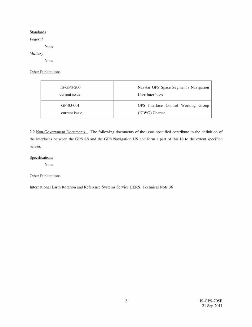
2.2 Non-Government Documents. The following documents of the issue specified contribute to the definition of
the interfaces between the GPS SS and the GPS Navigation US and form a part of this IS to the extent specified
herein.
Specifications
None
Other Publications
International Earth Rotation and Reference Systems Service (IERS) Technical Note 36
3 IS-GPS-705B
21 Sep 2011
3. REQUIREMENTS
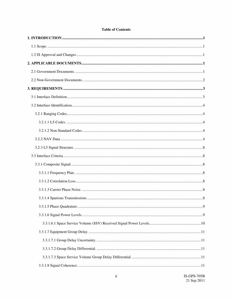
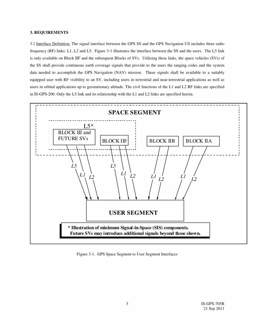
3.1 Interface Definition. The signal interface between the GPS SS and the GPS Navigation US includes three radio
frequency (RF) links: L1, L2 and L5. Figure 3-1 illustrates the interface between the SS and the users. The L5 link
is only available on Block IIF and the subsequent Blocks of SVs. Utilizing these links, the space vehicles (SVs) of
the SS shall provide continuous earth coverage signals that provide to the users the ranging codes and the system
data needed to accomplish the GPS Navigation (NAV) mission. These signals shall be available to a suitably
equipped user with RF visibility to an SV, including users in terrestrial and near-terrestrial applications as well as
users in orbital applications up to geostationary altitude. The civil functions of the L1 and L2 RF links are specified
in IS-GPS-200. Only the L5 link and its relationship with the L1 and L2 links are specified herein.
Figure 3-1. GPS Space Segment to User Segment Interfaces
L5*
SPACE SEGMENT
USER SEGMENT
BLOCK IIABLOCK IIRBLOCK IIF
BLOCK III and
FUTURE SVs
L5
L1
* Illustration of minimum Signal-in-Space (SIS) components.
Future SVs may introduce additional signals beyond those shown.
L5
L2L1
L2 L1L2
L1L2
4 IS-GPS-705B
21 Sep 2011
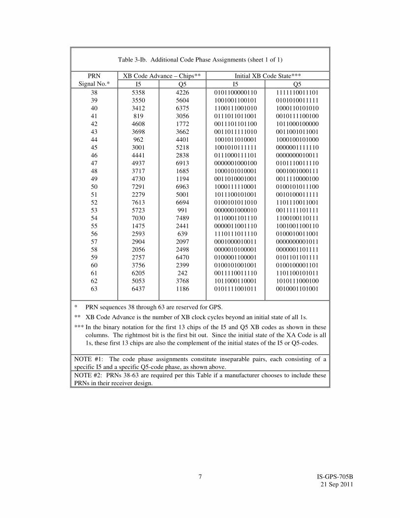
3.2 Interface Identification. The carriers of the L5 are typically modulated by two bit trains in phase quadrature.
One is a composite bit train generated by the modulo-2 addition of a pseudo-random noise (PRN) ranging code, a
synchronization sequence (see paragraph 3.3.3.1.2), and the downlink system data (referred to as L5 CNAV (civil
navigation) data), and the second is modulated with a PRN ranging code and synchronization sequence (see
paragraph 3.3.2.3) that differ from those used with the L5 CNAV data.
3.2.1 Ranging Codes. Two PRN ranging codes are transmitted on L5: the in-phase code (denoted as the I5-code);
and the quadraphase code (denoted as the Q5-code). Code-division-multiple-access techniques allow differentiating
between the SVs even though they may transmit at the same L5 frequency. The SVs shall transmit intentionally
"incorrect" versions of the I5 and the Q5-codes when needed to protect the users from receiving and utilizing
anomalous NAV signals. These two "incorrect" codes are termed non-standard I5 (NSI5) and non-standard Q5
(NSQ5) codes.
3.2.1.1 L5-Codes. The PRN ranging codes I5i(t) and Q5i(t) for SV ID number i are independent, but time
synchronized, 1 millisecond in length, with a chipping rate of 10.23 Mbps. For each code, the 1-millisecond
sequences are the modulo-2 sum of two sub-sequences referred to as XA and XBi; their lengths are 8,190 chips and
8,191 chips, respectively that restart to generate the 10,230 chip code. The XBi sequence is selectively advanced,
thereby allowing the basic code generation technique to produce different code sequences of 1-millisecond in length.
Of these, 32 pairs are currently designated for use by SVs and 5 pairs are currently reserved. Assignment of these
code phase segments by SV ID number (or other use) is given in Table 3-I. SV ID and PRN numbers are identical to
those for the L1 and L2 signals as specified in IS-GPS-200.
The 74 codes (37 I5-codes and 37 Q5-codes) are a selected subset of over 4,000 possible codes that could be
generated using the selective advance. The remaining codes are available for future use of additional SVs and/or
other L5 signal applications such as Satellite-Based Augmentation System (SBAS) satellite signals. Of the
remaining codes, Section 6.3.4 provides a selected subset of codes with assigned PRN numbers.
3.2.1.2 Non-Standard Codes. The NSI5 and NSQ5 codes, used to protect the user from tracking anomalous
navigation signals are not for utilization by the user and, therefore, are not defined in this document. The SVs shall
also be capable of initiating and terminating the broadcast of NSI5 and/or NSQ5 code(s) independently of each
other, in response to Control Segment (CS) command.
3.2.2 NAV Data. The L5 CNAV data, D5(t), includes SV ephemerides, system time, SV clock behavior data, status
messages and C/A to P (or Y) code handover information, etc. The 50 bps data is encoded in a rate 1/2 convolution
encoder. The resulting 100 symbols per second (sps) symbol stream is modulo-2 added to the I5-code only; the
resultant bit-train is used to modulate the L5 in-phase (I) carrier. The content and characteristics of the L5 CNAV
data, D5(t), are given in Appendix II of this document. In general, the data content is very similar to that modulated
on the L2 C channel of the SV.
The L5 quadraphase (Q5) carrier has no data.

5 IS-GPS-705B
21 Sep 2011
Table 3-Ia. Code Phase Assignments (sheet 1 of 2)
GPS PRN
Signal No.
XB Code Advance – Chips* Initial XB Code State**
I5 Q5 I5 Q5
1
2
3
4
5
6
7
8
9
10
11
12
13
14
15
16
17
18
19
266
365
804
1138
1509
1559
1756
2084
2170
2303
2527
2687
2930
3471
3940
4132
4332
4924
5343
1701
323
5292
2020
5429
7136
1041
5947
4315
148
535
1939
5206
5910
3595
5135
6082
6990
3546
0101011100100
1100000110101
0100000001000
1011000100110
1110111010111
0110011111010
1010010011111
1011110100100
1111100101011
0111111011110
0000100111010
1110011111001
0001110011100
0100000100111
0110101011010
0001111001001
0100110001111
1111000011110
1100100011111
1001011001100
0100011110110
1111000100011
0011101101010
0011110110010
0101010101001
1111110000001
0110101101000
1011101000011
0010010000110
0001000000101
0101011000101
0100110100101
1010000111111
1011110001111
1101001011111
1110011001000
1011011100100
0011001011011
* - XB Code Advance is the number of XB clock cycles beyond an initial state of all 1s.
** In the binary notation for the first 13 chips of the I5 and Q5 XB codes as shown in these
columns. The rightmost bit is the first bit out. Since the initial state of the XA Code is all
1s, these first 13 chips are also the complement of the initial states of the I5 or Q5-codes.
NOTE: The code phase assignments constitute inseparable pairs, each consisting of a specific
I5 and a specific Q5-code phase, as shown above.

6 IS-GPS-705B
21 Sep 2011
Table 3-Ia. Code Phase Assignments (sheet 2 of 2)
GPS PRN
Signal No.
XB Code Advance – Chips* Initial XB Code State**
I5 Q5 I5 Q5
20
21
22
23
24
25
26
27
28
29
30
31
32
33
34
35
36
37
5443
5641
5816
5898
5918
5955
6243
6345
6477
6518
6875
7168
7187
7329
7577
7720
7777
8057
1523
4548
4484
1893
3961
7106
5299
4660
276
4389
3783
1591
1601
749
1387
1661
3210
708
0110101101101
0010000001000
1110111101111
1000011111110
1100010110100
1101001101101
1010110010110
0101011011110
0111101010110
0101111100001
1000010110111
0001010011110
0000010111001
1101010000001
1101111111001
1111011011100
1001011001000
0011010010000
1100001110001
0110110010000
0010110001110
1000101111101
0110111110011
0100010011011
0101010111100
1000011111010
1111101000010
0101000100100
1000001111001
0101111100101
1001000101010
1011001000100
1111001000100
0110010110011
0011110101111
0010011010001
* XB Code Advance is the number of XB clock cycles beyond an initial state of all 1s.
** In the binary notation for the first 13 chips of the I5 and Q5 XB codes as shown in these
columns. The rightmost bit is the first bit out. Since the initial state of the XA Code is all
1s, these first 13 chips are also the complement of the initial states of the I5 or Q5-codes.
NOTE: The code phase assignments constitute inseparable pairs, each consisting of a specific
I5 and a specific Q5-code phase, as shown above.
7 IS-GPS-705B
21 Sep 2011
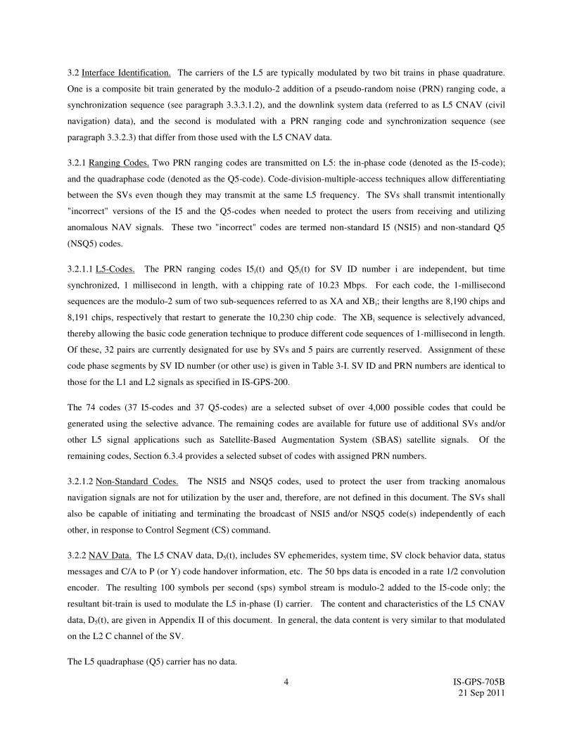
Table 3-Ib. Additional Code Phase Assignments (sheet 1 of 1)
PRN
Signal No.*
XB Code Advance – Chips** Initial XB Code State***
I5 Q5 I5 Q5
38
39
40
41
42
43
44
45
46
47
48
49
50
51
52
53
54
55
56
57
58
59
60
61
62
63
5358
3550
3412
819
4608
3698
962
3001
4441
4937
3717
4730
7291
2279
7613
5723
7030
1475
2593
2904
2056
2757
3756
6205
5053
6437
4226
5604
6375
3056
1772
3662
4401
5218
2838
6913
1685
1194
6963
5001
6694
991
7489
2441
639
2097
2498
6470
2399
242
3768
1186
0101100000110
1001001100101
1100111001010
0111011011001
0011101101100
0011011111010
1001011010001
1001010111111
0111000111101
0000001000100
1000101010001
0011010001001
1000111110001
1011100101001
0100101011010
0000001000010
0110001101110
0000011001110
1110111011110
0001000010011
0000010100001
0100001100001
0100101001001
0011110011110
1011000110001
0101111001011
1111110011101
0101010011111
1000110101010
0010111100100
1011000100000
0011001011001
1000100101000
0000001111110
0000000010011
0101110011110
0001001000111
0011110000100
0100101011100
0010100011111
1101110011001
0011111101111
1100100110111
1001001100110
0100010011001
0000000001011
0000001101111
0101101101111
0100100001101
1101100101011
1010111000100
0010001101001
* PRN sequences 38 through 63 are reserved for GPS.
** XB Code Advance is the number of XB clock cycles beyond an initial state of all 1s.
*** In the binary notation for the first 13 chips of the I5 and Q5 XB codes as shown in these
columns. The rightmost bit is the first bit out. Since the initial state of the XA Code is all
1s, these first 13 chips are also the complement of the initial states of the I5 or Q5-codes.
NOTE #1: The code phase assignments constitute inseparable pairs, each consisting of a
specific I5 and a specific Q5-code phase, as shown above.
NOTE #2: PRNs 38-63 are required per this Table if a manufacturer chooses to include these
PRNs in their receiver design.
8 IS-GPS-705B
21 Sep 2011
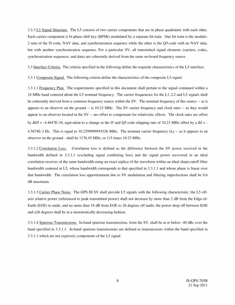
3.2.3 L5 Signal Structure. The L5 consists of two carrier components that are in phase quadrature with each other.
Each carrier component is bi-phase shift key (BPSK) modulated by a separate bit train. One bit train is the modulo-
2 sum of the I5-code, NAV data, and synchronization sequence while the other is the Q5-code with no NAV data,
but with another synchronization sequence. For a particular SV, all transmitted signal elements (carriers, codes,
synchronization sequences, and data) are coherently derived from the same on-board frequency source.
3.3 Interface Criteria. The criteria specified in the following define the requisite characteristics of the L5 interface.
3.3.1 Composite Signal. The following criteria define the characteristics of the composite L5 signal.
3.3.1.1 Frequency Plan. The requirements specified in this document shall pertain to the signal contained within a
24 MHz band centered about the L5 nominal frequency. The carrier frequencies for the L1, L2 and L5 signals shall
be coherently derived from a common frequency source within the SV. The nominal frequency of this source -- as it
appears to an observer on the ground -- is 10.23 MHz. The SV carrier frequency and clock rates -- as they would
appear to an observer located in the SV -- are offset to compensate for relativistic effects. The clock rates are offset
by Δf/f = -4.4647E-10, equivalent to a change in the I5 and Q5-code chipping rate of 10.23 MHz offset by a Δf = -
4.5674E-3 Hz. This is equal to 10.2299999954326 MHz. The nominal carrier frequency (f0) -- as it appears to an
observer on the ground - shall be 1176.45 MHz, or 115 times 10.23 MHz.
3.3.1.2 Correlation Loss. Correlation loss is defined as the difference between the SV power received in the
bandwidth defined in 3.3.1.1 (excluding signal combining loss) and the signal power recovered in an ideal
correlation receiver of the same bandwidth using an exact replica of the waveform within an ideal sharp-cutoff filter
bandwidth centered at L5, whose bandwidth corresponds to that specified in 3.3.1.1 and whose phase is linear over
that bandwidth. The correlation loss apportionment due to SV modulation and filtering imperfections shall be 0.6
dB maximum.
3.3.1.3 Carrier Phase Noise. The GPS III SV shall provide L5 signals with the following characteristic: the L5 off-
axis relative power (referenced to peak transmitted power) shall not decrease by more than 2 dB from the Edge-of-
Earth (EOE) to nadir, and no more than 18 dB from EOE to 26 degrees off nadir; the power drop off between EOE
and ±26 degrees shall be in a monotonically decreasing fashion.
3.3.1.4 Spurious Transmissions. In-band spurious transmissions, from the SV, shall be at or below -40 dBc over the
band specified in 3.3.1.1. In-band spurious transmissions are defined as transmissions within the band specified in
3.3.1.1 which are not expressly components of the L5 signal.
9 IS-GPS-705B
21 Sep 2011
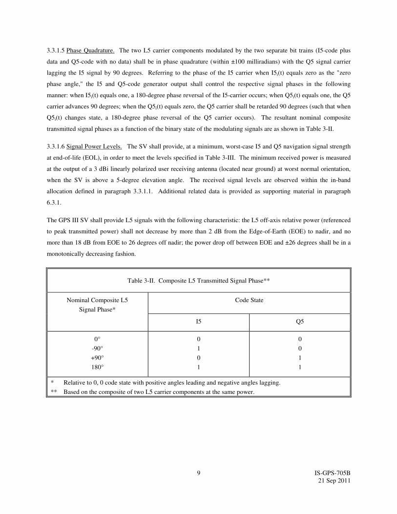
3.3.1.5 Phase Quadrature. The two L5 carrier components modulated by the two separate bit trains (I5-code plus
data and Q5-code with no data) shall be in phase quadrature (within ±100 milliradians) with the Q5 signal carrier
lagging the I5 signal by 90 degrees. Referring to the phase of the I5 carrier when I5i(t) equals zero as the "zero
phase angle," the I5 and Q5-code generator output shall control the respective signal phases in the following
manner: when I5i(t) equals one, a 180-degree phase reversal of the I5-carrier occurs; when Q5i(t) equals one, the Q5
carrier advances 90 degrees; when the Q5i(t) equals zero, the Q5 carrier shall be retarded 90 degrees (such that when
Q5i(t) changes state, a 180-degree phase reversal of the Q5 carrier occurs). The resultant nominal composite
transmitted signal phases as a function of the binary state of the modulating signals are as shown in Table 3-II.
3.3.1.6 Signal Power Levels. The SV shall provide, at a minimum, worst-case I5 and Q5 navigation signal strength
at end-of-life (EOL), in order to meet the levels specified in Table 3-III. The minimum received power is measured
at the output of a 3 dBi linearly polarized user receiving antenna (located near ground) at worst normal orientation,
when the SV is above a 5-degree elevation angle. The received signal levels are observed within the in-band
allocation defined in paragraph 3.3.1.1. Additional related data is provided as supporting material in paragraph
6.3.1.
The GPS III SV shall provide L5 signals with the following characteristic: the L5 off-axis relative power (referenced
to peak transmitted power) shall not decrease by more than 2 dB from the Edge-of-Earth (EOE) to nadir, and no
more than 18 dB from EOE to 26 degrees off nadir; the power drop off between EOE and ±26 degrees shall be in a
monotonically decreasing fashion.
Table 3-II. Composite L5 Transmitted Signal Phase**
Nominal Composite L5
Signal Phase*
Code State
I5 Q5
0°
-90°
+90°
180°
0
1
0
1
0
0
1
1
* Relative to 0, 0 code state with positive angles leading and negative angles lagging.
** Based on the composite of two L5 carrier components at the same power.
10 IS-GPS-705B
21 Sep 2011
Table 3-III. Received Minimum RF Signal Strength
SV Blocks
Signal
I5 Q5
IIF -157.9 dBW -157.9 dBW
III -157.0 dBW -157.0 dBW
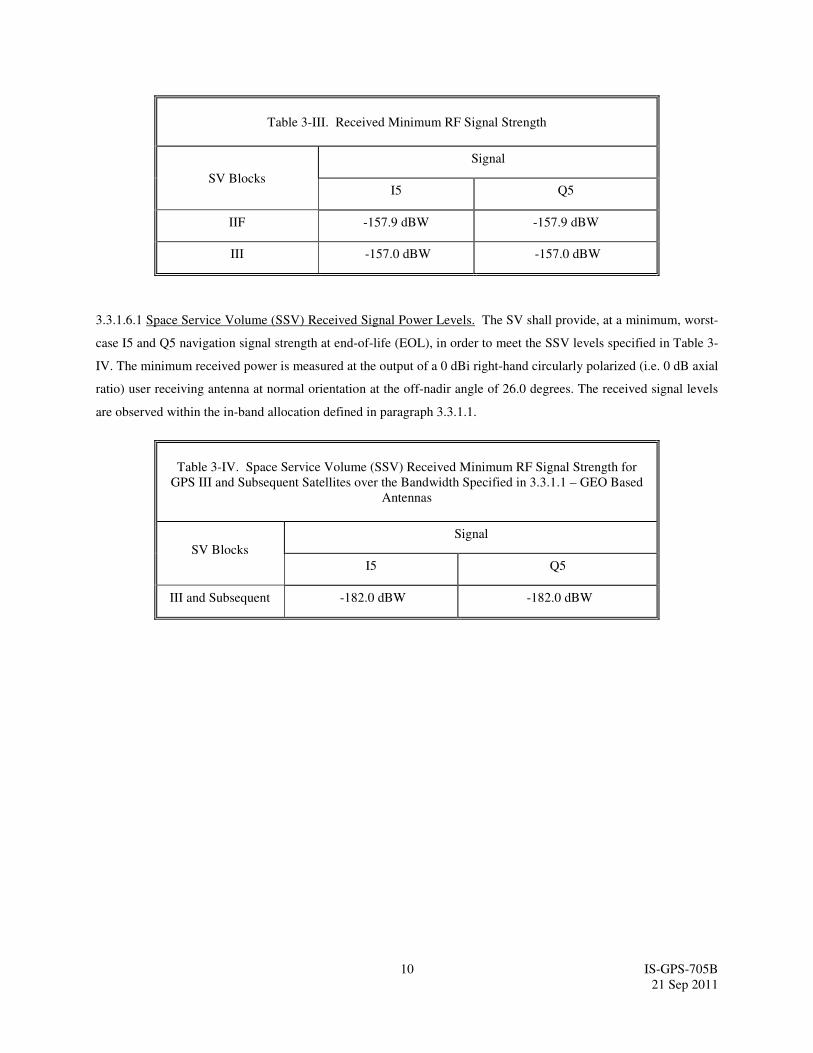
3.3.1.6.1 Space Service Volume (SSV) Received Signal Power Levels. The SV shall provide, at a minimum, worst-
case I5 and Q5 navigation signal strength at end-of-life (EOL), in order to meet the SSV levels specified in Table 3-
IV. The minimum received power is measured at the output of a 0 dBi right-hand circularly polarized (i.e. 0 dB axial
ratio) user receiving antenna at normal orientation at the off-nadir angle of 26.0 degrees. The received signal levels
are observed within the in-band allocation defined in paragraph 3.3.1.1.
Table 3-IV. Space Service Volume (SSV) Received Minimum RF Signal Strength for
GPS III and Subsequent Satellites over the Bandwidth Specified in 3.3.1.1 – GEO Based
Antennas
SV Blocks
Signal
I5 Q5
III and Subsequent -182.0 dBW -182.0 dBW

11 IS-GPS-705B
21 Sep 2011
3.3.1.7 Equipment Group Delay. Equipment group delay is defined as the delay between the signal radiated output
of a specific SV (measured at the antenna phase center) and the output of that SV's on-board frequency source; the
delay consists of a bias term and an uncertainty. The bias term on L1/L2 P(Y) is of no concern to users since it is
included in the clock correction parameters relayed in the NAV data, and is therefore accounted for by user
computations of system time (reference paragraphs 20.3.3.2.3, 20.3.3.3.2.3 and 20.3.3.3.2.4). The uncertainty
(variation) of these delays as well as the group delay differential between the signals of L1, L2, and L5 are defined
in the following.
3.3.1.7.1 Group Delay Uncertainty. The effective uncertainty of the group delays shall not exceed 3.0 nanoseconds
(95% probability).
3.3.1.7.2 Group Delay Differential. The group delay differential between the radiated L1 and L5 signals (i.e. L1
P(Y) and L5 I5; and L1 P(Y) and L5 Q5) is specified as consisting of random plus bias components. The mean
differential is defined as the bias component and will be either positive or negative. For a given navigation payload
redundancy configuration, the absolute value of the mean differential delay shall not exceed 30.0 nanoseconds. The
random plus non-random variations about the mean shall not exceed 3.0 nanoseconds (95% probability), when
including consideration of the temperature and antenna effects during a vehicle orbital revolution. L1 and L2 group
delay differential is described in 3.3.1.7.2 of IS-GPS-200. Corrections for the bias components of the group delay
differential are provided to the users in the NAV message using parameters designated as TGD (reference paragraph
20.3.3.3.3.2 of IS-GPS-200) and Inter-Signal Correction (ISC) (reference paragraph 20.3.3.3.1.2).
3.3.1.7.3 Space Service Volume Group Delay Differential. The group delay differential between the radiated L5
signal, with respect to the Earth Coverage signal, for users of the Space Service Volume are provided in
http://www.igs.org/products/ssv
3.3.1.8 Signal Coherence. All transmitted signals on the same carrier for a particular SV shall be coherently derived
from the same on-board frequency standard. On the L5 channel, the chip transitions of the two modulating signals,
L5I and L5Q, shall be such that the average time difference between them, and between each and the transitions of
L1 P(Y), do not exceed 10 nanoseconds. The variable time difference shall not exceed 1 nanosecond (95%
probability), when including consideration of the temperature and antenna effect changes during a vehicle orbital
revolution. Corrections for the bias components of the group delay differential are provided to the users using
parameters designated as ISCs (reference paragraph 20.3.3.3.1.2).
3.3.1.9 Signal Polarization. The transmitted signal shall be right-hand circularly polarized (RHCP). For the angular
range of ±13.8 degrees from nadir, L5 ellipticity shall be no worse than 2.4 dB. Nominal values are listed in section
6.3.3.
12 IS-GPS-705B
21 Sep 2011
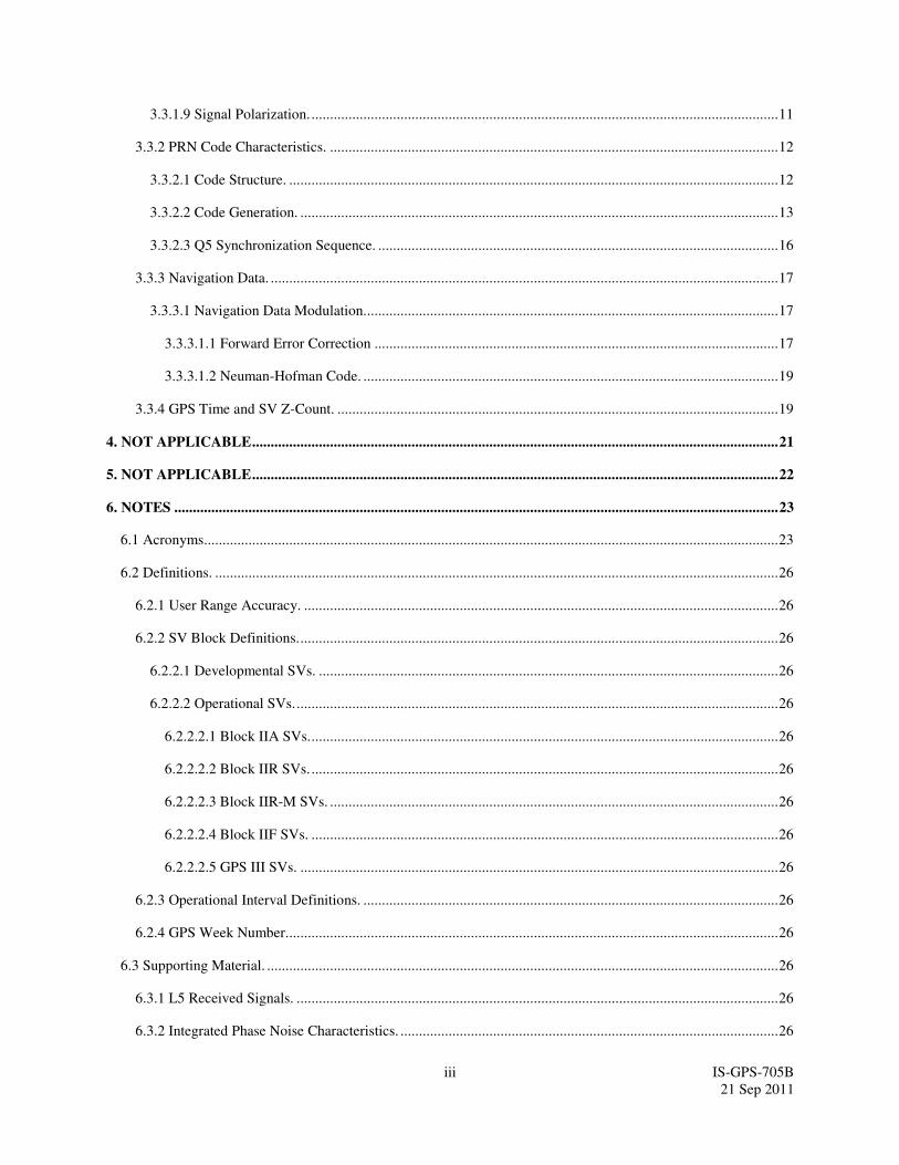
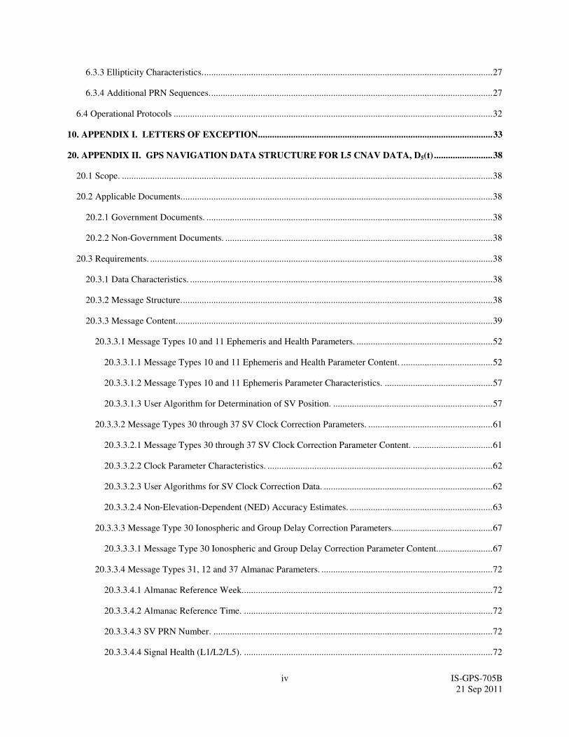
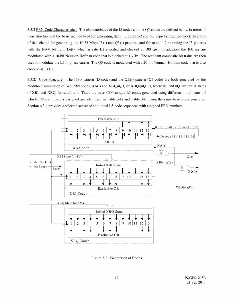
3.3.2 PRN Code Characteristics. The characteristics of the I5-codes and the Q5-codes are defined below in terms of
their structure and the basic method used for generating them. Figures 3-2 and 3-3 depict simplified block diagrams
of the scheme for generating the 10.23 Mbps I5i(t) and Q5i(t) patterns, and for modulo-2 summing the I5 patterns
with the NAV bit train, D5(t), which is rate 1/2 encoded and clocked at 100 sps. In addition, the 100 sps are
modulated with a 10-bit Neuman-Hofman code that is clocked at 1 kHz. The resultant composite bit trains are then
used to modulate the L5 in-phase carrier. The Q5-code is modulated with a 20-bit Neuman-Hofman code that is also
clocked at 1 kHz.
3.3.2.1 Code Structure. The I5i(t) pattern (I5-code) and the Q5i(t) pattern (Q5-code) are both generated by the
modulo-2 summation of two PRN codes, XA(t) and XBIi(nIi, t) or XBQi(nQi, t), where nIi and nQi are initial states
of XBIi and XBQi for satellite i. There are over 4000 unique L5 codes generated using different initial states of
which 128 are currently assigned and identified in Table 3-Ia and Table 3-Ib using the same basic code generator.
Section 6.3.4 provides a selected subset of additional L5-code sequences with assigned PRN numbers.
1
Exclusive OR
Initial XBI State
Exclusive OR
All 1's
1 ms Epoch
Code Clock
XA(t)
XBI(t-n iTC)
XIi(t)
XA Coder
XBI State for SV i
Reset
Decode 1111111111101
Reset to all 1s on next clock2 3 4 5 109876 11 12 13
1 2 3 4 5 109876 11 12 13
XQ i(t)
XBQ(t-n iTC)
XBI Coder
XBQ Coder
Initial XBQ State
XBQ State for SV i
Exclusive OR
1 2 3 4 5 109876 11 12 13
Figure 3-2. Generation of Codes
13 IS-GPS-705B
21 Sep 2011
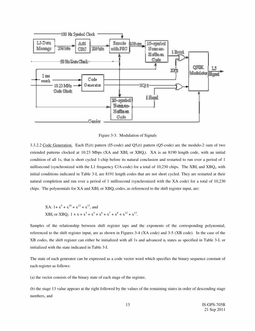
Figure 3-3. Modulation of Signals
3.3.2.2 Code Generation. Each I5i(t) pattern (I5-code) and Q5i(t) pattern (Q5-code) are the modulo-2 sum of two
extended patterns clocked at 10.23 Mbps (XA and XBIi or XBQi). XA is an 8190 length code, with an initial
condition of all 1s, that is short cycled 1-chip before its natural conclusion and restarted to run over a period of 1
millisecond (synchronized with the L1 frequency C/A-code) for a total of 10,230 chips. The XBIi and XBQi, with
initial conditions indicated in Table 3-I, are 8191 length codes that are not short cycled. They are restarted at their
natural completion and run over a period of 1 millisecond (synchronized with the XA code) for a total of 10,230
chips. The polynomials for XA and XBIi or XBQi codes, as referenced to the shift register input, are:
XA: 1+ x9 + x
10 + x
12 + x
13, and
XBIi or XBQi: 1 + x + x3 + x
4 + x
6 + x
7 + x
8 + x
12 + x
13.
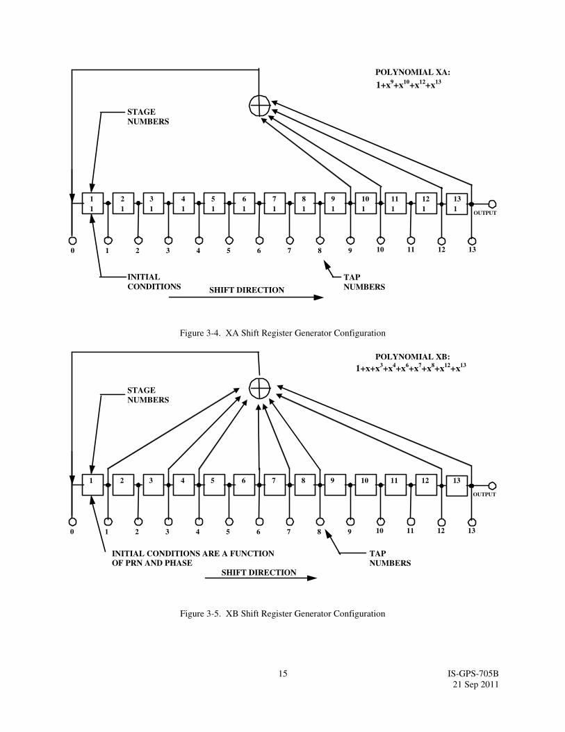
Samples of the relationship between shift register taps and the exponents of the corresponding polynomial,
referenced to the shift register input, are as shown in Figures 3-4 (XA code) and 3-5 (XB code). In the case of the
XB codes, the shift register can either be initialized with all 1s and advanced ni states as specified in Table 3-I, or
initialized with the state indicated in Table 3-I.
The state of each generator can be expressed as a code vector word which specifies the binary sequence constant of
each register as follows:
(a) the vector consists of the binary state of each stage of the register,
(b) the stage 13 value appears at the right followed by the values of the remaining states in order of descending stage
numbers, and

14 IS-GPS-705B
21 Sep 2011
(c) the shift direction is from lower to higher stage number with stage 13 providing the current output. This code
vector convention represents the present output and 12 future outputs in sequence. Using this convention, at each
XA epoch (state 8190), the XA shift register is initialized to the code vector 1111111111111, while at each XB
epoch (state 8191), the XB shift register is initialized to a code vector peculiar to the PRN number and phase. The
XB code vectors are as indicated in Table 3-I. Alternatively, the XB shift register is initialized to the code vector
1111111111111 and advanced ni states as indicated in Table 3-I.
The natural 8191 chips of the XA sequence is shortened to 8190 chips to cause precession of the second XA
sequence with respect to the natural 8191 chip XB sequence, as shown in Figure 3-6. Re-initialization of the XA
shift register produces a 10230-chip sequence by omitting the last 6151 chips of the second natural XA sequence, or
reinitializing to all 1s at the 1 ms epoch. The XB shift register is simply allowed to run its natural course until the
next 1 ms epoch when it is reinitialized at its initial state, B0, based upon PRN number and phase. This results in
the phase of the XB sequence leading by one chip during the second XA sequence in the 1-millisecond period.
Depending upon the initial state of the XB sequence, a third 8191-chip sequence may be started before the 10230-
chip sequence is completed. Two different scenarios that may result are shown in Figure 3-6.
In scenario a, the initial state of the XB sequence, B0, is less than State 6152. Thus, the second natural XB sequence
does not run to completion prior to the next 1 ms epoch. In scenario b, the initial state of the XB sequence, B0, is
greater than State 6151. Thus, the second natural XB sequence runs to completion and a third natural sequence
starts (except when B0 is State 6152) prior to the next 1 ms epoch.
15 IS-GPS-705B
21 Sep 2011
1
STAGE
NUMBERS
INITIAL
CONDITIONS SHIFT DIRECTION
0
TAP
NUMBERS
POLYNOMIAL XA:
OUTPUT
1+x9+x
10+x
12+x
13
1 2 3 4 5 6 7 8 9 10 11 12 13
1
2
1
3
1
4
1
5
1
6
1
7
1
8
1
9
1
10
1
11
1
12
1
13
1
Figure 3-4. XA Shift Register Generator Configuration
POLYNOMIAL XB:
OUTPUT
1+x+x3+x
4+x
6+x
7+x
8+x
12+x
13
STAGE
NUMBERS
INITIAL CONDITIONS ARE A FUNCTION
OF PRN AND PHASE
SHIFT DIRECTION
TAP
NUMBERS
1
0 1 2 3 4 5 6 7 8 9 10 11 12 13
2 3 4 5 6 7 8 9 10 11 12 13
Figure 3-5. XB Shift Register Generator Configuration

16 IS-GPS-705B
21 Sep 2011
Figure 3-6. Relative Phases between the XA and XB Sequences
3.3.2.3 Q5 Synchronization Sequence. In scenario b, the initial state of the XB sequence, B0, is greater than State
6151. Thus, the second natural XB sequence runs to completion and a third natural sequence starts (except when B0
is State 6152) prior to the next 1 ms epoch.
Each of the 1 ms Q5-code blocks is further encoded with a 20-bit Neuman-Hofman code. The 20 bits are modulo-2
added to the Q5 code chips at the PRN code epoch rate of 1 kHz. The code, nh20(t), starting coincident with the 20
ms data epoch on the I5 channel, is as follows:
1st Last
nh20(t) = 0 0 0 0 0 1 0 0 1 1 0 1 0 1 0 0 1 1 1 0
b) B0 = Initial State at 1 ms (greater than State 6151)
XB Code B0
XA Code 1
1
1 ms = 10230
8190
a) B0 = Initial State at 1 ms (less than State 6152)
9
2
1 = 1111111111111 8 = 1111111111101 9 = 1111111111110 2 = State 2040
1 8
B0
1
1 = 1111111111111 8 = 1111111111101 9 = 1111111111110 2 = State 2040
XA Code
1 ms = 10230
8191
XB Code 1 9
1 8 2 1 1
B0 1 9
B0
8190

17 IS-GPS-705B
21 Sep 2011
3.3.3 Navigation Data.
3.3.3.1 Navigation Data Modulation. The L5 CNAV bit train, D5(t), is rate 1/2 convolution encoded and, thus,
clocked at 100 symbols per second (sps). In addition, the 100 sps symbols are modulated with a 10-bit Neuman-
Hofman code that is clocked at 1 kHz (reference paragraph 3.3.3.1.2). The resultant symbol sequence is then
modulo-2 added with I5 PRN code and used to modulate the L5 in-phase carrier.
3.3.3.1.1 Forward Error Correction The L5 CNAV bit train, D5(t), will always be rate 1/2 convolution encoded with
a Forward Error Correction (FEC) code. Therefore, the symbol rate is 100 sps. The convolution coding will be
constraint length 7, with a convolution encoder logic arrangement as illustrated in Figure 3-7. The G1 symbol is
selected on the output as the first half of a 20-millisecond data bit period coincident with the first bit of the 20-bit Q5
Neuman-Hofman code.
Six-second navigation messages broadcast by the SV are synchronized with every fourth of the SV’s P(Y)-code X1
epochs. Although these epochs are not necessarily accessible to the L5 user, they are used within the SV to define
GPS time. However, message synchronization does provide the L5 user an access to the time of every 4th
P(Y)-code
X1 epoch. The navigation message is FEC encoded in a continuous process independent of message boundaries (i.e.
at the beginning of each new message, the encoder registers illustrated in Figure 3-7 contain the last six bits of the
previous message). Thus, herein, reference will continue to be made to these X1 epochs. See IS-GPS-200 for
details.
The FEC encoding convolves successive messages. It is necessary to define which transmitted symbol is
synchronized to SV time as follows. The beginning of the first symbol that contains any information about the first
bit of a message will be synchronized to every fourth X1 epoch (referenced to end/start of week). The users’
convolution decoders will introduce a fixed delay that depends on their respective algorithms (usually 5 constraint
lengths, or 35 bits), for which they must compensate to determine system time from the received signal. This
convolution decoding delay and the various relationships with the start of the data block transmission and SV timing
are illustrated in Figure 3-8 for the L5 signal.

18 IS-GPS-705B
21 Sep 2011
Figure 3-7. Convolution Encoder
Figure 3-8. Convolution transmit/Decoding Timing Relationships
G1 (171 OCTAL)
G2 (133 OCTAL)
DATA INPUT
(50BPS)
SYMBOL
CLOCK
OUTPUT SYMBOLS
(100 SPS)
(ALTERNATING G1/G2)
ENCODED
DATA BLOCK
RECEIVED BY
USER
DATA BLOCK
DECODED BY
USER
USER’S DECODING DELAY
DOWNLINK DELAY
LATER
ENCODED DATA BLOCK
TRANSMITTED ON L5
EARLY
SV 6 SECOND EPOCHS

19 IS-GPS-705B
21 Sep 2011
3.3.3.1.2 Neuman-Hofman Code. Each of the 100 sps symbols are further encoded with a 10-bit Neuman-Hofman
code. The 10-bit Neuman-Hofman code is defined to be 0000110101. The 10 bits are modulo-2 added to the
symbols at the PRN code epoch rate of 1 kHz starting at the 100 sps symbol transitions. The result is that a "1" data
symbol is replaced by 1111001010, and a "0" data symbol is replaced by 0000110101.
3.3.4 GPS Time and SV Z-Count. GPS time is established by the Operational Control System (OCS) and is
referenced to Coordinated Universal Time (UTC) as maintained by the U.S. Naval Observatory (UTC (USNO)) zero
time-point defined as midnight on the night of January 5, 1980/morning of January 6, 1980. GPS time is the
ensemble of corrected composite L1/L2 P(Y) SV times, corrected via the clock corrections in the L1 and L2 NAV
data and the relativity correction. The largest unit used in stating GPS time is one week defined as 604,800 seconds,
concatenated with the GPS week number. GPS time may differ from UTC because GPS time is a continuous time
scale, while UTC is corrected periodically with an integer number of leap seconds. There also is an inherent but
bounded drift rate between the UTC and GPS time scales. The OCS controls the GPS time scale to be within one
microsecond of UTC (modulo one second).
The L5 CNAV data contains the requisite data for relating GPS time to UTC. The accuracy of this data during the
transmission interval will be such that it relates GPS time to UTC (USNO) to within 90.0 nanoseconds (one sigma).
This data is generated by the CS (or provided to the CS); therefore, the accuracy of these relationships may degrade
if for some reason the CS is unable to upload data to an SV.
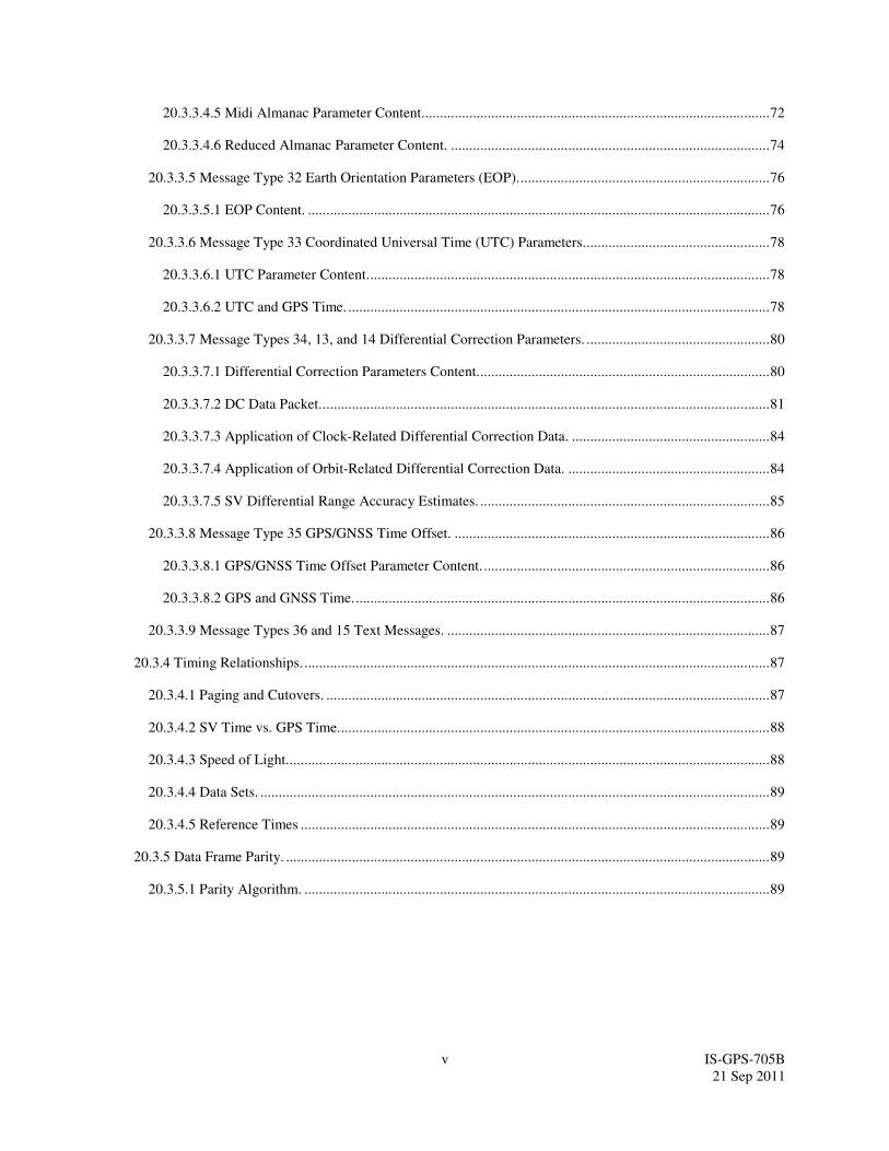
In each SV the X1 epochs of the P-code offer a convenient unit for precisely counting and communicating time.
Time stated in this manner is referred to as Z-count, which is given as a binary number consisting of two parts as
follows:
a. The binary number represented by the 19 least significant bits of the Z-count is referred to as the
time of week (TOW) count and is defined as being equal to the number of X1 epochs that have occurred since the
transition from the previous week. The count is short-cycled such that the range of the TOW-count is from 0 to
403,199 X1 epochs (equaling one week) and is reset to zero at the end of each week. The TOW-count's zero state is
defined as that X1 epoch which is coincident with the start of the present week. This epoch occurs at
(approximately) midnight Saturday night-Sunday morning, where midnight is defined as 0000 hours on the UTC
scale, which is nominally referenced to the Greenwich Meridian. Over the years the occurrence of the "zero state
epoch" may differ by a few seconds from 0000 hours on the UTC scale since UTC is periodically corrected with
leap seconds while the TOW-count is continuous without such correction. A truncated version of the TOW-count,
consisting of its 17 most significant bits, is contained in each of the six-second messages of the L5 downlink data
stream; the relationship between the actual TOW-count and its truncated message version is illustrated by Figure 3-
9.
b. The most significant bits of the Z-count are a binary representation of the sequential number
assigned to the current GPS week (see paragraph 6.2.4).

20 IS-GPS-705B
21 Sep 2011
Figure 3-9. Time Line Relationship of a Six-Second Message
403,192 403,196 403,199
P(Y)-CODE EPOCH
(END/START OF WEEK)
10 2 3 4 5 6 7 8
100,799 10 2 3
X1 EPOCHS 1.5 sec
DECIMAL EQUIVALENTSOF ACTUAL TOW COUNTS
MESSAGE EPOCHS
DECIMAL EQUIVALENTS OF MESSAGE TOW COUNTS
NOTES:
1.
2.
THE TOW COUNT APPEARS IN EACH 6-SECOND MESSAGE
3.
THE 6-SECOND MESSAGE TOW COUNT CONSISTS OF THE 17 MSBs OF THE
ACTUAL TOW COUNT AT THE START OF THE NEXT MESSAGE.
TO CONVERT FROM THE MESSAGE TOW COUNT TO THE ACTUAL TOW
COUNT AT THE START OF THE NEXT MESSAGE, MULTIPLY BY FOUR.
6 sec
21 IS-GPS-705B
21 Sep 2011
4. NOT APPLICABLE

22 IS-GPS-705B
21 Sep 2011
5. NOT APPLICABLE
23 IS-GPS-705B
21 Sep 2011
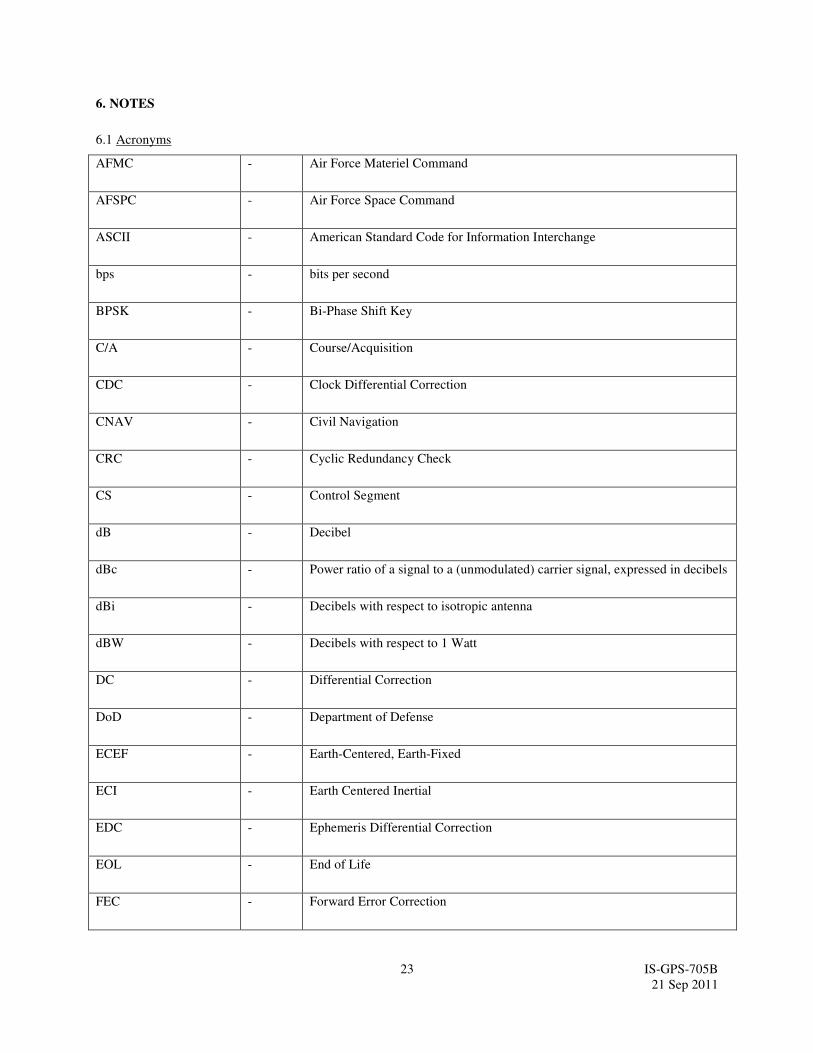
6. NOTES
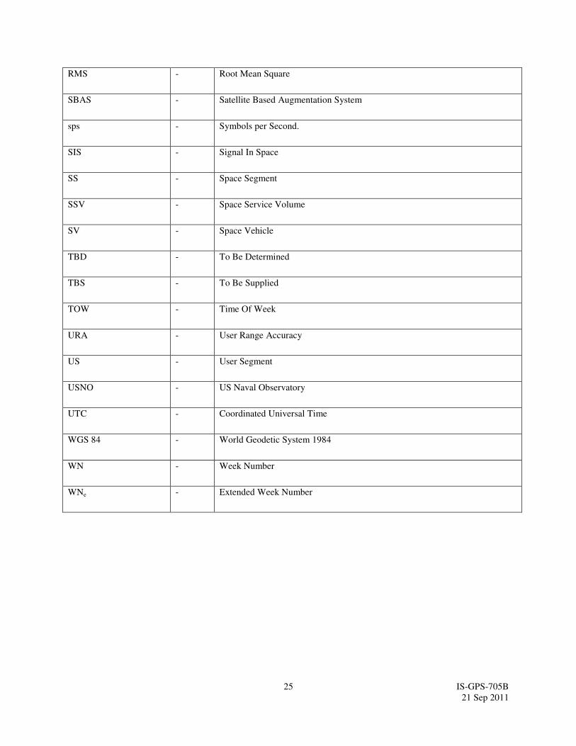
6.1 Acronyms
AFMC - Air Force Materiel Command
AFSPC - Air Force Space Command
ASCII - American Standard Code for Information Interchange
bps - bits per second
BPSK - Bi-Phase Shift Key
C/A - Course/Acquisition
CDC - Clock Differential Correction
CNAV - Civil Navigation
CRC - Cyclic Redundancy Check
CS - Control Segment
dB - Decibel
dBc - Power ratio of a signal to a (unmodulated) carrier signal, expressed in decibels
dBi - Decibels with respect to isotropic antenna
dBW - Decibels with respect to 1 Watt
DC - Differential Correction
DoD - Department of Defense
ECEF - Earth-Centered, Earth-Fixed
ECI - Earth Centered Inertial
EDC - Ephemeris Differential Correction
EOL - End of Life
FEC - Forward Error Correction

24 IS-GPS-705B
21 Sep 2011
GGTO - GPS/GNSS Time Offset
GNSS - Global Navigation Satellite System
GPS - Global Positioning System
GPSW - Global Positioning System Wing
Hz - Hertz
I5 - In-phase Code on L5 Signal
ICC - Interface Control Contractor
ID - Identification
IODC - Issue of Data, Clock
IS - Interface Specification
ISC - Inter-Signal Correction
LSB - Least Significant Bit
MSB - Most Significant Bit
NAV - Navigation
NSI5 - Non-Standard I-Code
NSQ5 - Non-Standard Q-Code
OCS - Operational Control System
PIRN - Proposed Interface Revision Notice
PRN - Pseudo-Random Noise
P(Y) - Precise (Anti-Spoof) Code
Q5 - Quadraphase code on L5 Signal
RF - Radio Frequency
RHCP - Right Hand Circular Polarization
25 IS-GPS-705B
21 Sep 2011
RMS - Root Mean Square
SBAS - Satellite Based Augmentation System
sps - Symbols per Second.
SIS - Signal In Space
SS - Space Segment
SSV - Space Service Volume
SV - Space Vehicle
TBD - To Be Determined
TBS - To Be Supplied
TOW - Time Of Week
URA - User Range Accuracy
US - User Segment
USNO - US Naval Observatory
UTC - Coordinated Universal Time
WGS 84 - World Geodetic System 1984
WN - Week Number
WNe - Extended Week Number
26 IS-GPS-705B
21 Sep 2011
6.2 Definitions.
6.2.1 User Range Accuracy. See Section 6.2.1 of IS-GPS-200.
6.2.2 SV Block Definitions. The following block definitions are given to facilitate discussion regarding the
capability of the various blocks of GPS satellites to support the SV-to-user interface.
6.2.2.1 Developmental SVs. See paragraph 6.2.2.1 of IS-GPS-200.
6.2.2.2 Operational SVs. The operational satellites are designated Block IIA, Block IIR, Block IIRM, Block IIF and
GPS III SVs. Characteristics of these SVs are provided below. These SVs transmit configuration codes as specified
in paragraph 20.3.3.5.1.4 of IS-GPS-200. The navigation signal provides no direct indication of the type of the
transmitting SV.
6.2.2.2.1 Block IIA SVs. See paragraph 6.2.2.2.2 of IS-GPS-200. These satellites do not broadcast the L5 signal.
6.2.2.2.2 Block IIR SVs. See paragraph 6.2.2.2.3 of IS-GPS-200. These satellites do not broadcast the L5 signal.
6.2.2.2.3 Block IIR-M SVs. See paragraph 6.2.2.2.4 of IS-GPS-200. These satellites do not broadcast the L5 signal.
6.2.2.2.4 Block IIF SVs. See paragraph 6.2.2.2.5 of IS-GPS-200. The IIF operational SVs do broadcast the L5
signal.
6.2.2.2.5 GPS III SVs. See paragraph 6.2.2.2.6 of IS-GPS-200. The III operational SVs do broadcast the L5 signal.
6.2.3 Operational Interval Definitions. See paragraph 6.2.3 of IS-GPS-200. There is no requirement for extended
operations on L5.
6.2.4 GPS Week Number. See paragraph 6.2.4 of IS-GPS-200 and paragraph 20.3.3.1.1.1.
6.3 Supporting Material.
6.3.1 L5 Received Signals. The guaranteed minimum user-received signal levels are defined in paragraph 3.3.1.6.
Higher received signal levels can be caused by such factors as SV attitude errors, mechanical antenna alignment
errors, transmitter power output variations resultant of temperature variations, voltage variations and power
amplifier variations, and a variability in link atmospheric path loss. In addition and for the purpose of establishing
GPS user receiver dynamic range, the maximum received signal level, as measured at the output of a 3 dBi linearly
polarized receiver antenna, is not expected to exceed -150.0 dBW in each L5 signal channel.
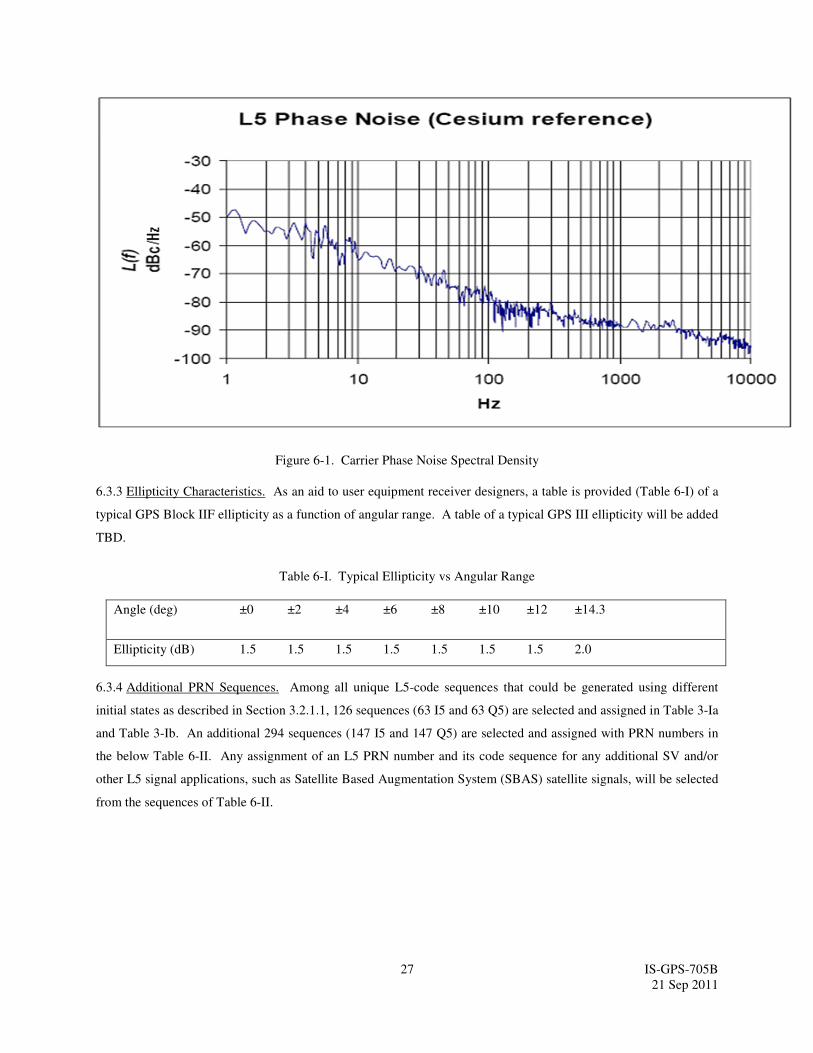
6.3.2 Integrated Phase Noise Characteristics. As an aid to user equipment receiver designers, a plot is provided
(Figure 6-1) of a typical GPS Block IIF phase noise spectral density for the un-modulated L5 carrier. A plot of a
typical GPS III phase noise spectral density will be added TBD.
27 IS-GPS-705B
21 Sep 2011
Figure 6-1. Carrier Phase Noise Spectral Density
6.3.3 Ellipticity Characteristics. As an aid to user equipment receiver designers, a table is provided (Table 6-I) of a
typical GPS Block IIF ellipticity as a function of angular range. A table of a typical GPS III ellipticity will be added
TBD.
Table 6-I. Typical Ellipticity vs Angular Range
Angle (deg) ±0 ±2 ±4 ±6 ±8 ±10 ±12 ±14.3
Ellipticity (dB) 1.5 1.5 1.5 1.5 1.5 1.5 1.5 2.0
6.3.4 Additional PRN Sequences. Among all unique L5-code sequences that could be generated using different
initial states as described in Section 3.2.1.1, 126 sequences (63 I5 and 63 Q5) are selected and assigned in Table 3-Ia
and Table 3-Ib. An additional 294 sequences (147 I5 and 147 Q5) are selected and assigned with PRN numbers in
the below Table 6-II. Any assignment of an L5 PRN number and its code sequence for any additional SV and/or
other L5 signal applications, such as Satellite Based Augmentation System (SBAS) satellite signals, will be selected
from the sequences of Table 6-II.

28 IS-GPS-705B
21 Sep 2011
Table 6-II. Additional Code Phase Assignments (sheet 1 of 5)
PRN
Signal No.
XB Code Advance – Chips** Initial XB Code State***
I5 Q5 I5 Q5
64
65
66
67
68
69
70
71
72
73
74
75
76
77
78
79
80
81
82
83
84
85
86
87
88
89
90
91
92
93
94
95
96
97
98
99
7789
2311
7432
5155
1593
5841
5014
1545
3016
4875
2119
229
7634
1406
4506
1819
7580
5446
6053
7958
5267
2956
3544
1277
2996
1758
3360
2718
3754
7440
2781
6756
7314
208
5252
696
5246
4259
5907
3870
3262
7387
3069
2999
7993
7849
4157
5031
5986
4833
5739
7846
898
2022
7446
6404
155
7862
7795
6121
4840
6585
429
6020
200
1664
1499
7298
1305
7323
7544
4438
1000100010001
0001000101111
0001100111111
1010101100001
0101011111001
0101101100001
1000101111011
0111011001111
0001011011000
1110000111000
0111010010001
0001101111000
1111001010100
1011101110100
0000100110000
1100010000111
0001101111111
1100110101101
1101011001011
1100001101100
1011110110001
0111010110101
1100101101101
1100111011111
1011111111011
1110100100111
1111110010100
0101001111110
0010100100101
0001111000011
1100111000000
1110010101000
0111000101001
1111101010101
1010111001101
1100101001011
1001101001111
0001100100010
0000111111000
0011100100111
0000001010010
1100111111001
0111111110010
0101011111111
1100001111011
1110100110101
1010010110101
0101111101111
1010110110010
1101110110001
1010000100100
0100110101010
1000011100011
1100111011010
0010110001111
1101101110110
1101111001001
1100100000000
1001101000100
1111011010001
0110101110111
0000100111111
1101101001110
1100111001011
1010111000011
1110110010110
1110100011111
0001101100011
0001011010110
0000001000111
1010011000000
1000111101101
** XB Code Advance is the number of XB clock cycles beyond an initial state of all 1s.
*** In the binary notation for the first 13 chips of the I5 and Q5 XB codes as shown in these
columns. The rightmost bit is the first bit out. Since the initial state of the XA Code is all
1s, these first 13 chips are also the complement of the initial states of the I5 or Q5-codes.
NOTE: The code phase assignments constitute inseparable pairs, each consisting of a specific
I5 and a specific Q5-code phase, as shown above.

29 IS-GPS-705B
21 Sep 2011
Table 6-II. Additional Code Phase Assignments (sheet 2 of 5)
PRN
Signal No.
XB Code Advance – Chips** Initial XB Code State***
I5 Q5 I5 Q5
100
101
102
103
104
105
106
107
108
109
110
111
112
113
114
115
116
117
118
119
120
121
122
123
124
125
126
127
128
129
527
1399
5879
6868
217
7681
3788
1337
2424
4243
5686
1955
4791
492
1518
6566
5349
506
113
1953
2797
934
3023
3632
1330
4909
4867
1183
3990
6217
2485
3387
7319
1853
5781
1874
7555
2132
6441
6722
1192
2588
2188
297
1540
4138
5231
4789
659
871
6837
1393
7383
611
4920
5416
1611
2474
118
1382
0010100000110
1101000010001
0111011010011
1101110101111
0111011011111
1010101001100
1011010000011
0101100000000
0000111101000
0110000111011
1101100100000
0011011101111
1001111101100
0100011000110
0111000101110
0100010110000
0110111100100
0001110010010
1110110110101
1101110111100
1101001100010
1100011001100
1000011000101
1111011011011
0000001100100
1101110000101
1100001000010
0001101001101
1010100101011
1111011110100
1101101011100
1000010110011
0010001110001
0010100100110
0100000111111
1000001111101
1010101111010
1111010101010
1101010111100
1111100001010
1111000010001
1101111011101
0010000100001
1100100111100
1100111100011
1001100001111
1110011001001
0111110110011
1111011010110
1000111011110
1101001011001
0010001111001
1111110011111
1000110000001
0000111100011
0111011011100
0101101010100
0000101010111
1010111101101
0100010000010
** XB Code Advance is the number of XB clock cycles beyond an initial state of all 1s.
*** In the binary notation for the first 13 chips of the I5 and Q5 XB codes as shown in these
columns. The rightmost bit is the first bit out. Since the initial state of the XA Code is all
1s, these first 13 chips are also the complement of the initial states of the I5 or Q5-codes.
NOTE: The code phase assignments constitute inseparable pairs, each consisting of a specific
I5 and a specific Q5-code phase, as shown above.

30 IS-GPS-705B
21 Sep 2011
Table 6-II. Additional Code Phase Assignments (sheet 3 of 5)
PRN
Signal No.
XB Code Advance – Chips** Initial XB Code State***
I5 Q5 I5 Q5
130
131
132
133
134
135
136
137
138
139
140
141
142
143
144
145
146
147
148
149
150
151
152
153
154
155
156
157
158
159
1224
1733
2319
3928
2380
841
5049
7027
1197
7208
8000
152
6762
3745
4723
5502
4796
123
8142
5091
7875
330
5272
4912
374
2045
6616
6321
7605
2570
1092
7950
7223
1769
4721
1252
5147
2165
7897
4054
3498
6571
2858
8126
7017
1901
181
1114
5195
7479
4186
3904
7128
1396
4513
5967
2580
2575
7961
2598
1111111101100
0000010000111
1111110000010
0011100111011
1101100010101
0101011111011
0001100011011
0001101110111
1110011110000
0111100011111
0011101110000
1111001001000
0001101110010
0101100111100
0010010111101
1101110110011
0011110011111
1001010101111
0111111101111
0000100100001
1110001101011
1111010010001
1011010111101
0001101110000
0000010111100
0100101111100
1110110111010
1101110101011
1101000110001
0100100010100
1010111011111
0110001000010
1011000011010
1000100000111
1001011110110
1000001011000
0000110010111
0010101101011
0011100001100
0100011001011
1010101001111
0100001000101
0000001111100
1101001110111
1110111110001
1110111010001
0001010110011
0111111000101
0100010011100
1110000010011
0110010101000
0000100000100
0100100101011
1000010001111
1110101000010
1110000111011
1110110010010
1001001001000
0011100001101
0000111101110
** XB Code Advance is the number of XB clock cycles beyond an initial state of all 1s.
*** In the binary notation for the first 13 chips of the I5 and Q5 XB codes as shown in these
columns. The rightmost bit is the first bit out. Since the initial state of the XA Code is all
1s, these first 13 chips are also the complement of the initial states of the I5 or Q5-codes.
NOTE: The code phase assignments constitute inseparable pairs, each consisting of a specific
I5 and a specific Q5-code phase, as shown above.
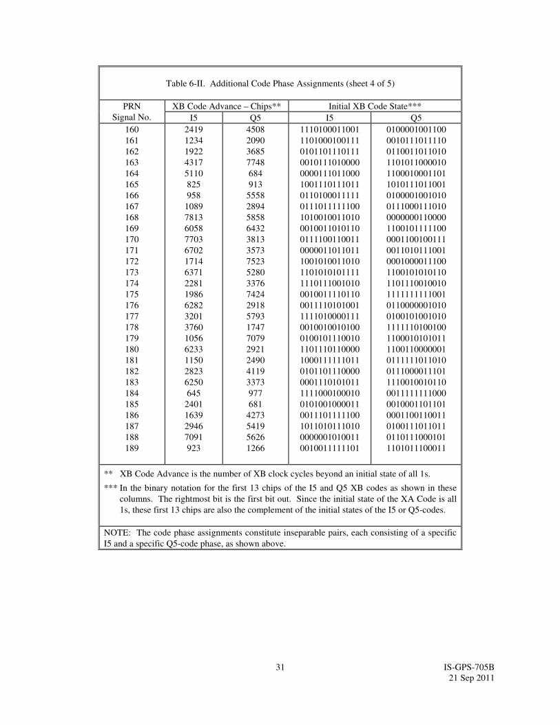
31 IS-GPS-705B
21 Sep 2011
Table 6-II. Additional Code Phase Assignments (sheet 4 of 5)
PRN
Signal No.
XB Code Advance – Chips** Initial XB Code State***
I5 Q5 I5 Q5
160
161
162
163
164
165
166
167
168
169
170
171
172
173
174
175
176
177
178
179
180
181
182
183
184
185
186
187
188
189
2419
1234
1922
4317
5110
825
958
1089
7813
6058
7703
6702
1714
6371
2281
1986
6282
3201
3760
1056
6233
1150
2823
6250
645
2401
1639
2946
7091
923
4508
2090
3685
7748
684
913
5558
2894
5858
6432
3813
3573
7523
5280
3376
7424
2918
5793
1747
7079
2921
2490
4119
3373
977
681
4273
5419
5626
1266
1110100011001
1101000100111
0101101110111
0010111010000
0000111011000
1001110111011
0110100011111
0111011111100
1010010011010
0010011010110
0111100110011
0000011011011
1001010011010
1101010101111
1110111001010
0010011110110
0011110101001
1111010000111
0010010010100
0100101110010
1101110110000
1000111111011
0101101110000
0001110101011
1111000100010
0101001000011
0011101111100
1011010111010
0000001010011
0010011111101
0100001001100
0010111011110
0110011011010
1101011000010
1100010001101
1010111011001
0100001001010
0111000111010
0000000110000
1100101111100
0001100100111
0011010111001
0001000011100
1100101010110
1101110010010
1111111111001
0110000001010
0100101001010
1111110100100
1100010101011
1100110000001
0111111011010
0111000011101
1110010010110
0011111111000
0010001101101
0001100110011
0100111011011
0110111000101
1101011100011
** XB Code Advance is the number of XB clock cycles beyond an initial state of all 1s.
*** In the binary notation for the first 13 chips of the I5 and Q5 XB codes as shown in these
columns. The rightmost bit is the first bit out. Since the initial state of the XA Code is all
1s, these first 13 chips are also the complement of the initial states of the I5 or Q5-codes.
NOTE: The code phase assignments constitute inseparable pairs, each consisting of a specific
I5 and a specific Q5-code phase, as shown above.

32 IS-GPS-705B
21 Sep 2011
Table 6-II. Additional Code Phase Assignments (sheet 5 of 5)
PRN
Signal No.
XB Code Advance – Chips** Initial XB Code State***
I5 Q5 I5 Q5
190
191
192
193
194
195
196
197
198
199
200
201
202
203
204
205
206
207
208
209
210
7045
6493
1706
5836
926
6086
950
5905
3240
6675
3197
1555
3589
4555
5671
6948
4664
2086
5950
5521
1515
5804
2414
6444
4757
427
5452
5182
6606
6531
4268
3115
6835
862
4856
2765
37
1943
7977
2512
4451
4071
1111100011000
1101101101100
1101010010110
0110000101110
0110010011111
1000111001100
1111101110001
0011111100001
0000001110001
1010110100100
0100001110110
0111110100011
0001111001011
1010100011011
1001101110011
0010111000001
1101100001111
1110111101001
0110110101101
0111110110010
1000101110111
1001110110001
0001100110110
1101101010111
1001110000111
0110100111010
0110001100110
0000100001100
0101000101101
1000001010111
0011001110001
0100011100110
0100101100101
1110001010111
1010110110100
1111101101000
1000001110100
1000010101100
1100001001101
1111111000011
0001011110011
1001000100001
** XB Code Advance is the number of XB clock cycles beyond an initial state of all 1s.
*** In the binary notation for the first 13 chips of the I5 and Q5 XB codes as shown in these
columns. The rightmost bit is the first bit out. Since the initial state of the XA Code is all
1s, these first 13 chips are also the complement of the initial states of the I5 or Q5-codes.
NOTE: The code phase assignments constitute inseparable pairs, each consisting of a specific
I5 and a specific Q5-code phase, as shown above.
6.4 Operational Protocols
See IS-GPS-200.
For a given satellite, the same PRN number will be assigned to all operational signals (signals modulated by
standard PRN code with data that indicates the signal health is OK).
See IS-GPS-200.
See IS-GPS-200.
33 IS-GPS-705B
21 Sep 2011
10. APPENDIX I. LETTERS OF EXCEPTION
Approval of this document, as well as approval of any subsequent changes to the document, can be contingent upon
a "letter of exception." This appendix depicts such "letters of exception" when authorized by the GPS Directorate.
The documents listed in Section 2.0 shall be applicable to this appendix.
Any letter of exception which is in force for the revision of the IS is depicted in Figure 10.3-1, 1-0.3-2, and 10.3-3.

34 IS-GPS-705B
21 Sep 2011
Figure 10.3-1. Letters of Exception

35 IS-GPS-705B
21 Sep 2011
Figure 10.3-2. Letters of Exception (continued).
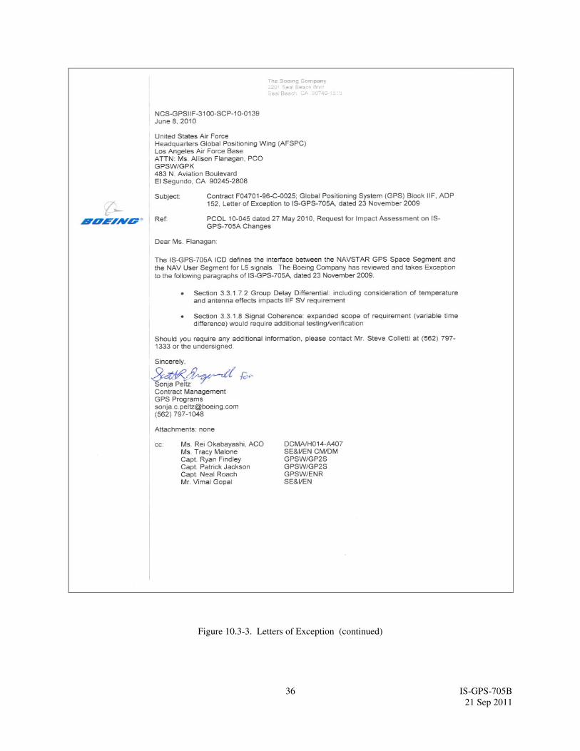
36 IS-GPS-705B
21 Sep 2011
Figure 10.3-3. Letters of Exception (continued)
37 IS-GPS-705B
21 Sep 2011
Figure 10.3-4. Letters of Exception (continued)

38 IS-GPS-705B
21 Sep 2011
20. APPENDIX II. GPS NAVIGATION DATA STRUCTURE FOR L5 CNAV DATA, D5(t)
20.1 Scope. This appendix describes the specific GPS L5 civil navigation (CNAV) data structure denoted by, D5(t).
20.2 Applicable Documents.
20.2.1 Government Documents. In addition to the documents listed in paragraph 2.1, the following documents of
the issue specified contribute to the definition of the CNAV data related interfaces and form a part of this Appendix
to the extent specified herein.
Specifications
None
Standards
None
Other Publications
None
20.2.2 Non-Government Documents. In addition to the documents listed in paragraph 2.2, the following documents
of the issue specified contribute to the definition of the CNAV data related interfaces and form a part of this
Appendix to the extent specified herein.
Specifications
None
Other Publications
None
20.3 Requirements.
20.3.1 Data Characteristics. The L5 channel data stream mostly contains the same data as the L2 C channel. The
data stream shall be transmitted by the SV on the L5 channel at the rate of 50 bps with rate 1/2 FEC resulting in 100
sps.
20.3.2 Message Structure. As shown in Figures 20-1 through 20-14, the L5 CNAV message structure utilizes a
basic format of six-second 300-bit long messages. Each message contains a Cyclic Redundancy Check (CRC)
parity block consisting of 24 bits covering the entire six-second message (300 bits) (reference Section 20.3.5).
Message type 0 (zero) is defined to be the default message. In the event of message generation failure, the SV shall
replace each affected message type with the default message type. In the event that a particular message is not
assigned (by the CS) a particular message type for broadcast, the SV shall generate and broadcast the default
message type in that message slot.

39 IS-GPS-705B
21 Sep 2011
Currently undefined and unused message types are reserved for future use.
Block IIF SVs have the capability of storing at least 48 hours of CNAV navigation data, with current memory
margins, to provide CNAV positioning service without contact from the CS for that period. GPS III SVs have the
capability of providing up to 60 days of CNAV positioning service without contact from the CS. The timeframe is
defined by the CS.
20.3.3 Message Content. Each message starts with an 8-bit preamble - 10001011, followed by a 6-bit PRN number
of the transmitting SV, a 6-bit message type ID with a range of 0 (000000) to 63 (111111), and the 17-bit message
time of week (TOW) count. When the value of the message TOW count is multiplied by 6, it represents SV time in
seconds at the start of the next 6-second message. An “alert” flag, when raised (bit 38 = “1”), indicates to the user
that the signal URA components may be worse than indicated in the associated message types and that he shall use
at his own risk. For each default message (Message Type 0), bits 39 through 276 shall be alternating ones and zeros
and the message shall contain a proper CRC parity block.
8 BITS
MESSAGE TYPE ID
6
BITS
PREAMBLE
PRN
6
BITS
MESSAGETOW COUNT*
17 BITS
"ALERT" FLAG - 1 BIT
9 2115 39
L5 HEALTH – 1 BIT
71
URA ED
INDEX
55 66
150
DIRECTION OF DATA FLOW FROM SV MSB FIRST
100 BITS 2 SECONDS
173
25 BITS
206
1
23 BITS
M 0-n
28 MSBs
CRC
24 BITS
277
3852
toe
11 BITS
239
L2 HEALTH – 1 BITL1 HEALTH – 1 BIT
101
17 BITS
201
5BITS
A•
∆
n 0•
∆
n 0
top
11 BITS
82
19 MSBs
∆A
133
33 BITS
en ωn
33 BITS
13 BITS
WN n
108
M 0-n
5 LSBs
DIRECTION OF DATA FLOW FROM SV MSB FIRST100 BITS 2 SECONDS
DIRECTION OF DATA FLOW FROM SV MSB FIRST
100 BITS 2 SECONDS
7 LSBs
∆ A
* MESSAGE TOW COUNT = 17 MSB OF ACTUAL TOW COUNT AT START OF NEXT 6 SECOND MESSAGE
272
RESERVED – 3 BITS
L2C PHASING – 1 BIT
INTEGRITY STATUS FLAG – 1 BIT
Figure 20-1. Message type 10 - Ephemeris 1
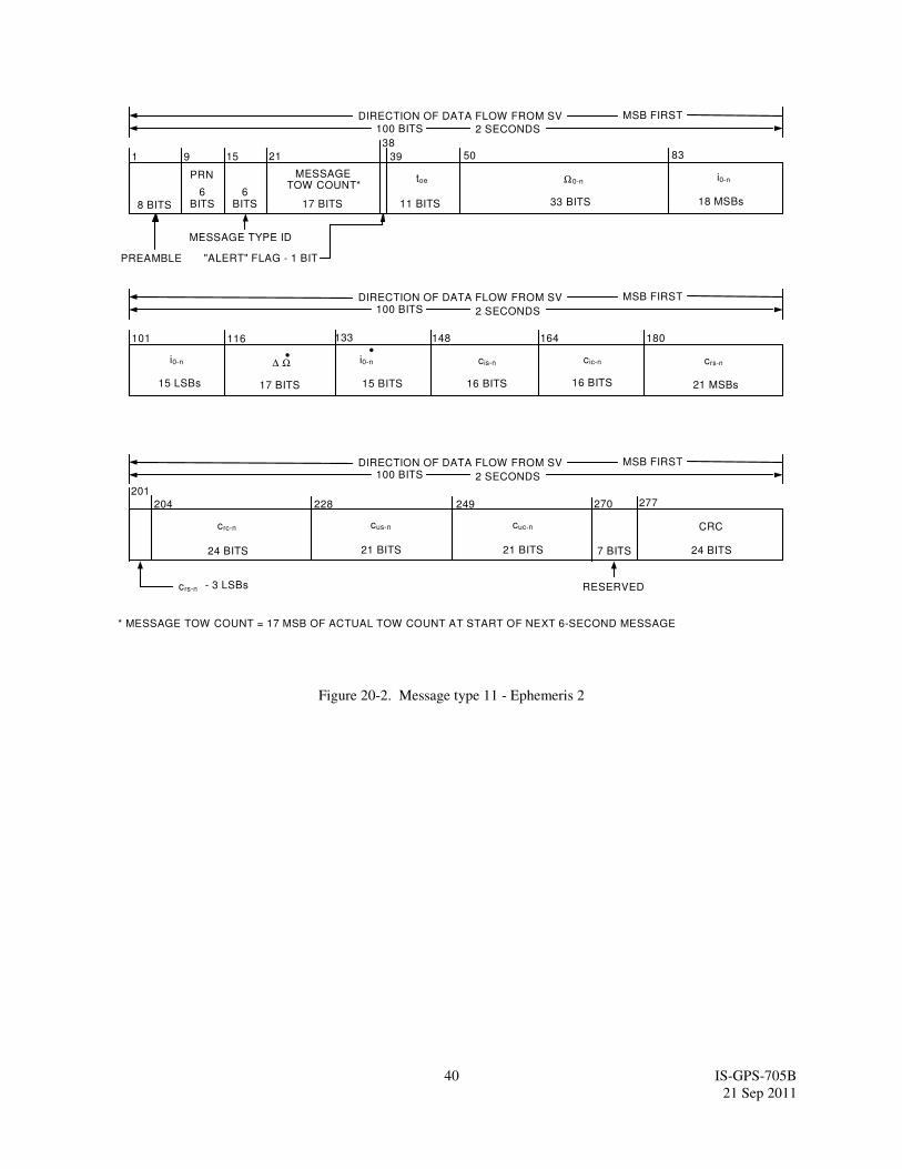
40 IS-GPS-705B
21 Sep 2011
8 BITS
MESSAGE TYPE ID
6 BITS
PREAMBLE
PRN
6 BITS
MESSAGE TOW COUNT*
17 BITS
"ALERT" FLAG - 1 BIT
9 21 15 39
148
DIRECTION OF DATA FLOW FROM SV MSB FIRST
100 BITS 2 SECONDS
164
17 BITS
204
1
16 BITS
270
crs-n
21 MSBs
CRC
24 BITS
277
38
50
* MESSAGE TOW COUNT = 17 MSB OF ACTUAL TOW COUNT AT START OF NEXT 6-SECOND MESSAGE
toe
RESERVED
7 BITS
228
101
15 BITS
201
∆ Ω • i0-n cis-n
11 BITS
83
18 MSBs
133
24 BITS
crc-n
15 LSBs
116
crs-n - 3 LSBs
DIRECTION OF DATA FLOW FROM SV MSB FIRST
100 BITS 2 SECONDS
DIRECTION OF DATA FLOW FROM SV MSB FIRST
100 BITS 2 SECONDS
33 BITS
Ω0-n i0-n
i0-n
16 BITS
c ic-n
180
249
21 BITS
cus-n
21 BITS
cuc-n
•
Figure 20-2. Message type 11 - Ephemeris 2
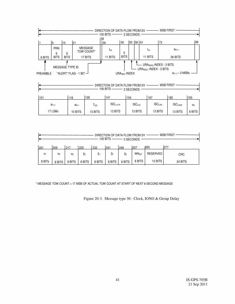
41 IS-GPS-705B
21 Sep 2011
154 167
10 BITS
209
13 BITS
257
ISCL5Q5
13 BITS
CRC
24 BITS
277
* MESSAGE TOW COUNT = 17 MSB OF ACTUAL TOW COUNT AT START OF NEXT 6-SECOND MESSAGE
RESERVED
12 BITS
233
101
13 BITS
201
af2-n ISCL1C/A ISCL2C
128
8 BITS
17 LSBs
118
DIRECTION OF DATA FLOW FROM SV MSB FIRST100 BITS 2 SECONDS
DIRECTION OF DATA FLOW FROM SV MSB FIRST
100 BITS 2 SECONDS
af1-n
13 BITS
ISCL5I5
180
249
α0
8 BITS13 BITS
TGD
141 193
α1
8 BITs
α2
8 BITS
α3
217 225
8 BITS
β0
8 BITS
β1
8 BITS
β2
8 BITS
β3
241
WNOP
8 BITS
265
8 BITS
MESSAGE TYPE ID
6 BITS
PREAMBLE
PRN
6 BITS
MESSAGETOW COUNT*
17 BITS
"ALERT" FLAG - 1 BIT
9 21 15 39
DIRECTION OF DATA FLOW FROM SV MSB FIRST
100 BITS 2 SECONDS
1
3850
top
11 BITS
98
11 BITS
toc
af1-n – 3 MSBs
5 BITS 26 BITS
af0-n
55 58 72
URANED2 INDEX - 3 BITS
61
URANED1 INDEX - 3 BITS
URANED INDEX
Figure 20-3. Message type 30 - Clock, IONO & Group Delay
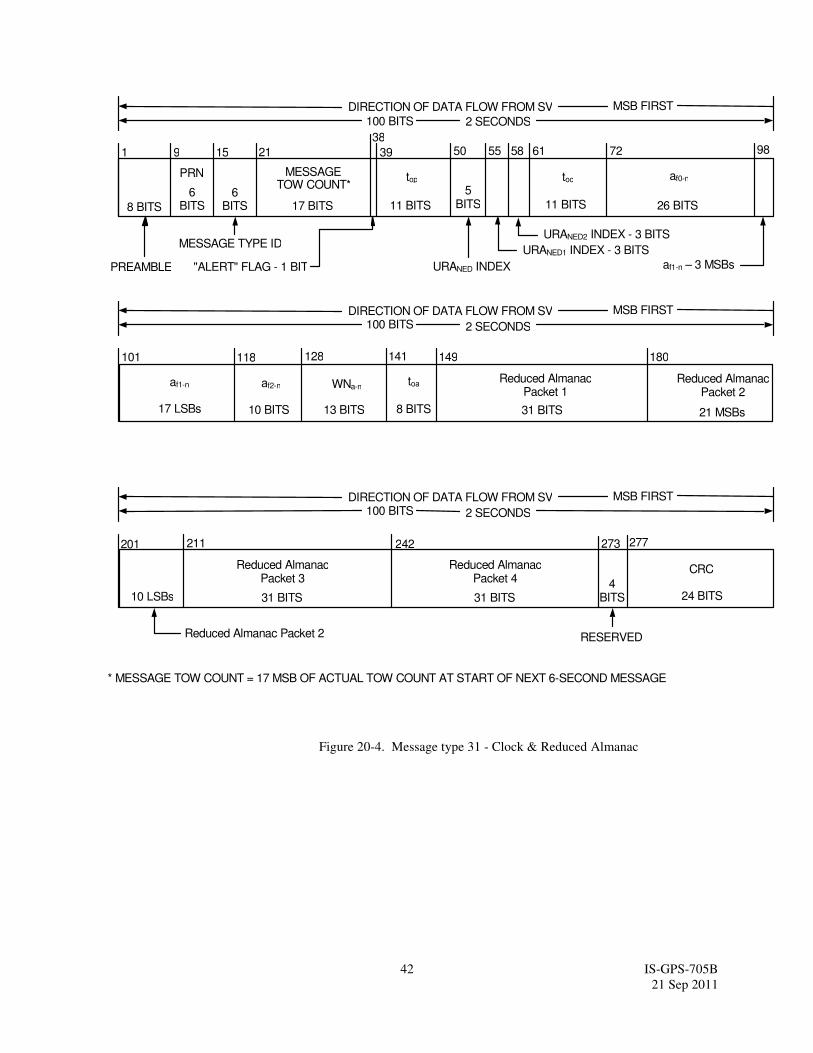
42 IS-GPS-705B
21 Sep 2011
149
10 BITS 31 BITS
273
Reduced AlmanacPacket 2
21 MSBs
CRC
24 BITS
277
* MESSAGE TOW COUNT = 17 MSB OF ACTUAL TOW COUNT AT START OF NEXT 6-SECOND MESSAGE
RESERVED
4 BITS
101
8 BITS
201
af2-n toaReduced Almanac
Packet 1
128
17 LSBs
118
DIRECTION OF DATA FLOW FROM SV MSB FIRST
100 BITS 2 SECONDS
DIRECTION OF DATA FLOW FROM SV MSB FIRST
100 BITS 2 SECONDS
af1-n
180
13 BITS
WNa-n
141
Reduced Almanac Packet 2
10 LSBs 31 BITS
Reduced AlmanacPacket 3
242
31 BITS
Reduced AlmanacPacket 4
211
8 BITS
MESSAGE TYPE ID
6 BITS
PREAMBLE
PRN
6 BITS
MESSAGETOW COUNT*
17 BITS
"ALERT" FLAG - 1 BIT
9 21 15 39
DIRECTION OF DATA FLOW FROM SV MSB FIRST
100 BITS 2 SECONDS
1
3850
top
11 BITS
98
11 BITS
toc
af1-n – 3 MSBs
5 BITS 26 BITS
af0-n
55 58 72
URANED2 INDEX - 3 BITS
61
URANED1 INDEX - 3 BITS
URANED INDEX
Figure 20-4. Message type 31 - Clock & Reduced Almanac
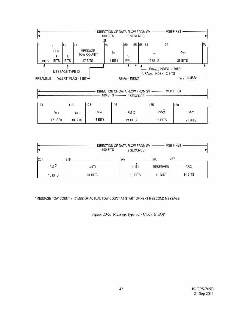
43 IS-GPS-705B
21 Sep 2011
165
10 BITS 21 BITS
266
PM-Y
15 BITS
CRC
24 BITS
277
* MESSAGE TOW COUNT = 17 MSB OF ACTUAL TOW COUNT AT START OF NEXT 6-SECOND MESSAGE
RESERVED
11 BITS
101
15 BITS
201
af2-n PM-X PM-Y
128
17 LSBs
118
DIRECTION OF DATA FLOW FROM SV MSB FIRST
100 BITS 2 SECONDS
DIRECTION OF DATA FLOW FROM SV MSB FIRST
100 BITS 2 SECONDS
af1-n
144
21 BITS
PM-X
180
31 BITS
∆UT1
247
19 BITS
216
•
•∆UT1
•
16 BITS
tEOP
8 BITS
MESSAGE TYPE ID
6 BITS
PREAMBLE
PRN
6 BITS
MESSAGETOW COUNT*
17 BITS
"ALERT" FLAG - 1 BIT
9 21 15 39
DIRECTION OF DATA FLOW FROM SV MSB FIRST
100 BITS 2 SECONDS
1
3850
top
11 BITS
98
11 BITS
toc
af1-n – 3 MSBs
5 BITS 26 BITS
af0-n
55 58 72
URANED2 INDEX - 3 BITS
61
URANED1 INDEX - 3 BITS
URANED INDEX
Figure 20-5. Message type 32 - Clock & EOP
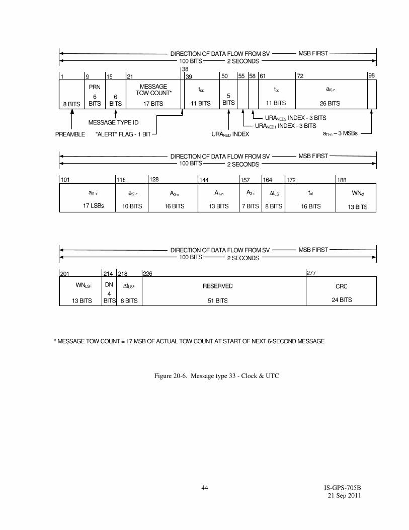
44 IS-GPS-705B
21 Sep 2011
144
10 BITS 16 BITS
226
WNot
13 BITS
CRC
24 BITS
277
* MESSAGE TOW COUNT = 17 MSB OF ACTUAL TOW COUNT AT START OF NEXT 6-SECOND MESSAGE
RESERVED
51 BITS
101
8 BITS
201
af2-n ∆tLS tot
128
17 LSBs
118
DIRECTION OF DATA FLOW FROM SV MSB FIRST
100 BITS 2 SECONDS
DIRECTION OF DATA FLOW FROM SV MSB FIRST
100 BITS 2 SECONDS
af1-n
188
16 BITS
A0-n
164
13 BITS
WNLSF
214
8 BITS
∆tLSF
7 BITS
A2-n
13 BITS
A1-n
172157
218
4 BITS
DN
8 BITS
MESSAGE TYPE ID
6 BITS
PREAMBLE
PRN
6 BITS
MESSAGETOW COUNT*
17 BITS
"ALERT" FLAG - 1 BIT
9 21 15 39
DIRECTION OF DATA FLOW FROM SV MSB FIRST
100 BITS 2 SECONDS
1
38
50
top
11 BITS
98
11 BITS
toc
af1-n – 3 MSBs
5 BITS 26 BITS
af0-n
55 58 72
URANED2 INDEX - 3 BITS
61
URANED1 INDEX - 3 BITS
URANED INDEX
Figure 20-6. Message type 33 - Clock & UTC
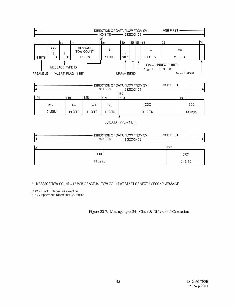
45 IS-GPS-705B
21 Sep 2011
139
10 BITS
EDC
16 MSBs
CRC
24 BITS
277
* MESSAGE TOW COUNT = 17 MSB OF ACTUAL TOW COUNT AT START OF NEXT 6-SECOND MESSAGE CDC = Clock Differential Correction EDC = Ephemeris Differential Correction
101
201
af2-n
128
17 LSBs
118
DIRECTION OF DATA FLOW FROM SV MSB FIRST
100 BITS 2 SECONDS
DIRECTION OF DATA FLOW FROM SV MSB FIRST
100 BITS 2 SECONDS
af1-n
185
11 BITS
top-D
76 LSBs
EDC
34 BITS
CDC
150
151
11 BITS
tOD
DC DATA TYPE – 1 BIT
8 BITS
MESSAGE TYPE ID
6 BITS
PREAMBLE
PRN
6 BITS
MESSAGETOW COUNT*
17 BITS
"ALERT" FLAG - 1 BIT
9 21 15 39
DIRECTION OF DATA FLOW FROM SV MSB FIRST
100 BITS 2 SECONDS
1
3850
top
11 BITS
98
11 BITS
toc
af1-n – 3 MSBs
5 BITS 26 BITS
af0-n
55 58 72
URANED2 INDEX - 3 BITS
61
URANED1 INDEX - 3 BITS
URANED INDEX
Figure 20-7. Message type 34 - Clock & Differential Correction

46 IS-GPS-705B
21 Sep 2011
144
10 BITS 13 BITS
RESERVED
5 BITS
CRC
24 BITS
277
* MESSAGE TOW COUNT = 17 MSB OF ACTUAL TOW COUNT AT START OF NEXT 6-SECOND MESSAGE
RESERVED
76 BITS
101
7 BITS
201
af2-n A2GGTOA1GGTO
128
17 LSBs
118
DIRECTION OF DATA FLOW FROM SV MSB FIRST
100 BITS 2 SECONDS
DIRECTION OF DATA FLOW FROM SV MSB FIRST
100 BITS 2 SECONDS
af1-n
196
16 BITS
tGGTO
189
16 BITS
A0GGTO
13 BITS
WNGGTO
176157 159
GNSS ID – 3 BITS
8 BITS
MESSAGE TYPE ID
6 BITS
PREAMBLE
PRN
6 BITS
MESSAGETOW COUNT*
17 BITS
"ALERT" FLAG - 1 BIT
9 21 15 39
DIRECTION OF DATA FLOW FROM SV MSB FIRST
100 BITS 2 SECONDS
1
38
50
top
11 BITS
98
11 BITS
toc
af1-n – 3 MSBs
5 BITS 26 BITS
af0-n
55 58 72
URANED2 INDEX - 3 BITS
61
URANED1 INDEX - 3 BITS
URANED INDEX
Figure 20-8. Message type 35 - Clock & GGTO

47 IS-GPS-705B
21 Sep 2011
10 BITS
CRC
24 BITS
277
* MESSAGE TOW COUNT = 17 MSBs OF ACTUAL TOW COUNT AT START OF NEXT 6-SECOND MESSAGE
RESERVED – 1 BIT
101
201
af2-n
128
17 LSBs
118
DIRECTION OF DATA FLOW FROM SV MSB FIRST
100 BITS 2 SECONDS
DIRECTION OF DATA FLOW FROM SV MSB FIRST
100 BITS 2 SECONDS
af1-n
71 LSBs
TEXT PAGE
TEXT MESSAGE (18 8-BIT CHAR)
73 MSBs
TEXT MESSAGE (18 8-BIT CHAR)
272276
4 BITS
8 BITS
MESSAGE TYPE ID
6 BITS
PREAMBLE
PRN
6 BITS
MESSAGETOW COUNT*
17 BITS
"ALERT" FLAG - 1 BIT
9 21 15 39
DIRECTION OF DATA FLOW FROM SV MSB FIRST
100 BITS 2 SECONDS
1
38
50
top
11 BITS
98
11 BITS
toc
af1-n – 3 MSBs
5 BITS 26 BITS
af0-n
55 58 72
URANED2 INDEX - 3 BITS
61
URANED1 INDEX - 3 BITS
URANED INDEX
Figure 20-9. Message type 36 - Clock & Text

48 IS-GPS-705B
21 Sep 2011
10 BITS
240
10 MSBs
CRC
24 BITS
277
* MESSAGE TOW COUNT = 17 MSBs OF ACTUAL TOW COUNT AT START OF NEXT 6-SECOND MESSAGE
11 BITS
101
11 BITS
201
af2-n δi
17 LSBs
118
DIRECTION OF DATA FLOW FROM SV MSB FIRST
100 BITS 2 SECONDS
DIRECTION OF DATA FLOW FROM SV MSB FIRST
100 BITS 2 SECONDS
af1-n
191169
16 BITS
Ω0
16 BITS
ω
11 BITS
e
141
8 BITS
WNa-n toa
13 BITS
A
180128
224
7 LSBs
M0
11 BITS
Ω•
A
208
16 BITS
256
af0
267
L5 HEALTH – 1 BIT
L2 HEALTH – 1 BIT
L1 HEALTH – 1 BIT
149
6 BITS
PRNa
155 158
10 BITS
af1
8 BITS
MESSAGE TYPE ID
6 BITS
PREAMBLE
PRN
6 BITS
MESSAGETOW COUNT*
17 BITS
"ALERT" FLAG - 1 BIT
9 21 15 39
DIRECTION OF DATA FLOW FROM SV MSB FIRST
100 BITS 2 SECONDS
1
38
50
top
11 BITS
98
11 BITS
toc
af1-n – 3 MSBs
5 BITS 26 BITS
af0-n
55 58 72
URANED2 INDEX - 3 BITS
61
URANED1 INDEX - 3 BITS
URANED INDEX
Figure 20-10. Message Type 37 - Clock & Midi Almanac
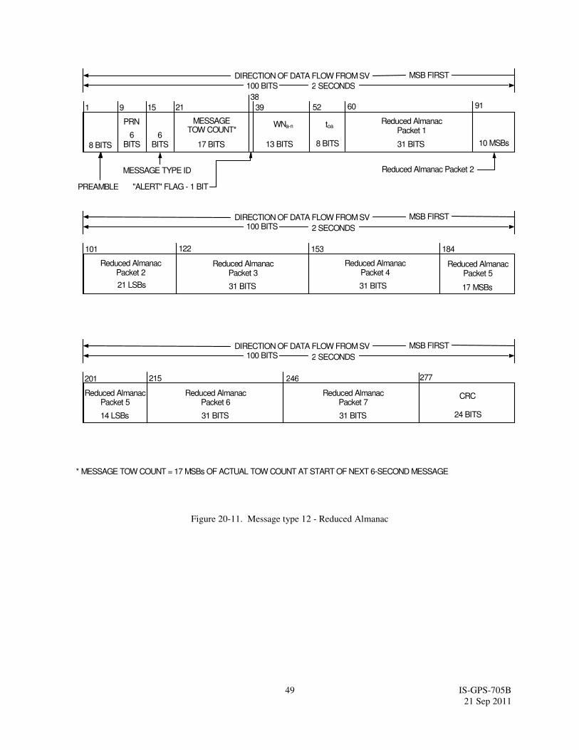
49 IS-GPS-705B
21 Sep 2011
8 BITS
MESSAGE TYPE ID
6 BITS
PREAMBLE
PRN
6 BITS
MESSAGE TOW COUNT*
17 BITS
"ALERT" FLAG - 1 BIT
9 21 15 39
153
DIRECTION OF DATA FLOW FROM SV MSB FIRST
100 BITS 2 SECONDS
1
31 BITS
215
Reduced Almanac Packet 5
17 MSBs
CRC
24 BITS
277
38
* MESSAGE TOW COUNT = 17 MSBs OF ACTUAL TOW COUNT AT START OF NEXT 6-SECOND MESSAGE
WNa-n
101
201
Reduced Almanac Packet 4
13 BITS
91
10 MSBs
122
21 LSBs
DIRECTION OF DATA FLOW FROM SV MSB FIRST
100 BITS 2 SECONDS
DIRECTION OF DATA FLOW FROM SV MSB FIRST
100 BITS 2 SECONDS
8 BITS
toa
Reduced Almanac Packet 2
184
31 BITS
Reduced Almanac Packet 1
60 52
31 BITS
Reduced Almanac Packet 3
31 BITS
Reduced Almanac Packet 6
246
31 BITS
Reduced Almanac Packet 7
Reduced Almanac Packet 2
14 LSBs
Reduced Almanac Packet 5
Figure 20-11. Message type 12 - Reduced Almanac

50 IS-GPS-705B
21 Sep 2011
8 BITS
MESSAGE TYPE ID
6 BITS
PREAMBLE
PRN
6 BITS
MESSAGE TOW COUNT*
17 BITS
"ALERT" FLAG - 1 BIT
9 21 15 39
DIRECTION OF DATA FLOW FROM SV MSB FIRST
100 BITS 2 SECONDS
1
CRC
24 BITS
277
38
50
* MESSAGE TOW COUNT = 17 MSBs OF ACTUAL TOW COUNT AT START OF NEXT 6-SECOND MESSAGE CDC = Clock Differential Correction
top-D
RESERVED
6 BITS
101
11 BITS
30 LSBs
DIRECTION OF DATA FLOW FROM SV MSB FIRST
100 BITS 2 SECONDS
DIRECTION OF DATA FLOW FROM SV MSB FIRST
100 BITS 2 SECONDS
11 BITS
tOD
CDC
34 BITS
CDC
CDC - 4 MSBs
34 BITS
CDC
62
61
97
96
DC DATA TYPE – 1 BIT DC DATA TYPE – 1 BIT
132
131
DC DATA TYPE – 1 BIT
167
166
DC DATA TYPE – 1 BIT
34 BITS
CDC
202
201
DC DATA TYPE – 1 BIT
34 BITS
CDC
237
236
DC DATA TYPE – 1 BIT
34 BITS
CDC
271
Figure 20-12. Message type 13 - Clock Differential Correction

51 IS-GPS-705B
21 Sep 2011
8 BITS
MESSAGE TYPE ID
6 BITS
PREAMBLE
PRN
6 BITS
MESSAGE TOW COUNT*
17 BITS
"ALERT" FLAG - 1 BIT
9 21 15 39
DIRECTION OF DATA FLOW FROM SV MSB FIRST
100 BITS 2 SECONDS
1
CRC
24 BITS
277
38
50
* MESSAGE TOW COUNT = 17 MSBs OF ACTUAL TOW COUNT AT START OF NEXT 6-SECOND MESSAGE EDC = Ephemeris Differential Correction
top-D
RESERVED
30 BITS
101
201
11 BITS
53 LSBs
DIRECTION OF DATA FLOW FROM SV MSB FIRST
100 BITS 2 SECONDS
DIRECTION OF DATA FLOW FROM SV MSB FIRST
100 BITS 2 SECONDS
11 BITS
tOD
EDC
39 MSBs
EDC
46 MSBs
46 LSBs
EDC
EDC
247
62
61
DC DATA TYPE – 1 BIT
155
154
DC DATA TYPE – 1 BIT
Figure 20-13. Message type 14 - Ephemeris Differential Correction
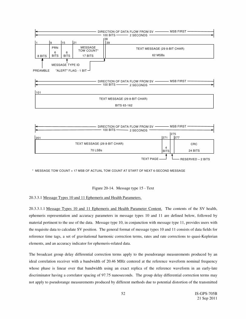
52 IS-GPS-705B
21 Sep 2011
8 BITS
MESSAGE TYPE ID
6 BITS
PREAMBLE
PRN
6 BITS
MESSAGE TOW COUNT*
17 BITS
"ALERT" FLAG - 1 BIT
9 21 15 39
DIRECTION OF DATA FLOW FROM SV MSB FIRST
100 BITS 2 SECONDS
1
CRC
24 BITS
277
38
* MESSAGE TOW COUNT = 17 MSB OF ACTUAL TOW COUNT AT START OF NEXT 6-SECOND MESSAGE
TEXT MESSAGE (29 8-BIT CHAR)
RESERVED – 2 BITS
101
201
62 MSBs
DIRECTION OF DATA FLOW FROM SV MSB FIRST
100 BITS 2 SECONDS
DIRECTION OF DATA FLOW FROM SV MSB FIRST
100 BITS 2 SECONDS
70 LSBs
TEXT PAGE
TEXT MESSAGE (29 8-BIT CHAR)
BITS 63-162
TEXT MESSAGE (29 8-BIT CHAR)
271
275
4 BITS
Figure 20-14. Message type 15 - Text
20.3.3.1 Message Types 10 and 11 Ephemeris and Health Parameters.
20.3.3.1.1 Message Types 10 and 11 Ephemeris and Health Parameter Content. The contents of the SV health,
ephemeris representation and accuracy parameters in message types 10 and 11 are defined below, followed by
material pertinent to the use of the data. Message type 10, in conjunction with message type 11, provides users with
the requisite data to calculate SV position. The general format of message types 10 and 11 consists of data fields for
reference time tags, a set of gravitational harmonic correction terms, rates and rate corrections to quasi-Keplerian
elements, and an accuracy indicator for ephemeris-related data.
The broadcast group delay differential correction terms apply to the pseudorange measurements produced by an
ideal correlation receiver with a bandwidth of 20.46 MHz centered at the reference waveform nominal frequency
whose phase is linear over that bandwidth using an exact replica of the reference waveform in an early-late
discriminator having a correlator spacing of 97.75 nanoseconds. The group delay differential correction terms may
not apply to pseudorange measurements produced by different methods due to potential distortion of the transmitted
53 IS-GPS-705B
21 Sep 2011
waveform. Users employing pseudorange measurement methods different from the defined method must account
for the potential inapplicability of the group delay differential correction terms.
The toe term shall provide the user with a convenient means for detecting any change in the ephemeris representation
parameters. The toe is provided in both message type 10 and 11 for the purpose of comparison with the toc term in
message type 30 - 37. Whenever these three terms do not match, a data set cutover has occurred and new data must
be collected. The timing of the toe and constraints on the toc and toe are defined in paragraph 20.3.4.4.
Any change in the message type 10 and 11 ephemeris data will be accomplished with a simultaneous change in the
toe value. The CS will assure the toe value for Block IIR-M/IIF and SS will assure the toe value for GPS III, for at
least the first data set transmitted by an SV after an upload, is different from that transmitted prior to the cutover.
See Section 20.3.4.5 for additional information regarding toe.
The CNAV messages contain information that allows users to take advantage of situations when integrity is assured
to the enhanced level. This is accomplished using a composite integrity assured URA value in conjunction with an
integrity status flag. The composite integrity assured URA (IAURA) value is the RSS of an elevation-dependent
function of the upper bound value of the URAED component and the upper bound value of the URANED component.
The composite IAURA value is assured to the enhanced level only when the integrity status flag is “1”; otherwise
the IAURA value is assured to the legacy level.
Bit 272 of Message Type 10 is the Integrity Status Flag (ISF). A "0" in bit position 272 indicates that the conveying
signal is provided with the legacy level of integrity assurance. That is, the probability that the instantaneous URE of
the conveying signal exceeds 4.42 times the current broadcast IAURA value, for more than 5.2 seconds, without an
accompanying alert, is less than 1E-5 per hour.
A "1" in bit-position 272 indicates that the conveying signal is provided with an enhanced level of integrity
assurance. That is, the probability that the instantaneous URE of the conveying signal exceeds 5.73 times the
current broadcast IAURA value, for more than 5.2 seconds, without an accompanying alert, is less than 1E-8 per
hour. The probabilities associated with the nominal and lower bound values of the current broadcast URAED index,
URANED indexes, and related URA values are not defined.
In this context, an "alert" is defined as any indication or characteristic of the conveying signal, as specified
elsewhere in this document, which signifies to users that the conveying signal may be invalid or should not be used,
such as the health bits not indicating operational-healthy, broadcasting non-standard code parity error, etc.
Bit 273 of Message Type 10 indicates the phase relationship between L2C and P(Y) as specified in section 3.3.1.5.1
of IS-GPS-200.
54 IS-GPS-705B
21 Sep 2011
20.3.3.1.1.1 Transmission Week Number. Bits 39 through 51 of message type 10 shall contain 13 bits which are a
modulo-8192 binary representation of the current GPS week number at the start of the data set transmission interval
(see paragraph 6.2.4 of IS-GPS-200).
20.3.3.1.1.2 Signal Health (L1/L2/L5). The three, one-bit, health indication in bits 52 through 54 of message type
10 refers to the L1, L2, and L5 signals of the transmitting SV. The health of each signal is indicated by,
0 = Signal OK,
1 = Signal bad or unavailable.
The predicted health data will be updated at the time of upload when a new data set has been built by the CS. The
transmitted health data may not correspond to the actual health of the transmitting SV.
Additional SV health data are given in the almanac in message types 12, 31, and 37. The data given in message type
10 may differ from that shown in the other messages of the transmitting SV and/or other SVs since the latter may be
updated at a different time.
20.3.3.1.1.3 Data Predict Time of Week. Bits 55 through 65 of message type 10 shall contain the data predict time
of week (top). The top term provides the epoch time of week of the state estimate utilized for the prediction of
satellite quasi-Keplerian ephemeris parameters.
20.3.3.1.1.4 Elevation-Dependent (ED) Accuracy
Bits 66 through 70 of message type 10 shall contain the elevation-dependent (ED) component User Range Accuracy
(URAED) index for the standard positioning service user. The URAED index shall provide the ED-related URA index
for the current ephemeris curve fit interval. While the ED-related URA may vary over the ephemeris curve fit
interval and over the satellite footprint, the URAED index (N) in message type 10 shall correspond to the maximum
URAED expected over the entire ephemeris curve fit interval for the worst-case location within the SV footprint (i.e.,
nominally two points at the edge of the SV footprint). At the best-case location within the SV footprint (i.e.,
nominally directly below the SV along the SV nadir vector), the corresponding URAED. is zero.

55 IS-GPS-705B
21 Sep 2011
URAED Index URAED (meters)
15 6144.00 < URAED (or no accuracy prediction is available)
14 3072.00 < URAED ≤ 6144.00
13 1536.00 < URAED ≤ 3072.00
12 768.00 < URAED ≤ 1536.00
11 384.00 < URAED ≤ 768.00
10 192.00 < URAED ≤ 384.00
9 96.00 < URAED ≤ 192.00
8 48.00 < URAED ≤ 96.00
7 24.00 < URAED ≤ 48.00
6 13.65 < URAED ≤ 24.00
5 9.65 < URAED ≤ 13.65
4 6.85 < URAED ≤ 9.65
3 4.85 < URAED ≤ 6.85
2 3.40 < URAED ≤ 4.85
1 2.40 < URAED ≤ 3.40
0 1.70 < URAED ≤ 2.40
-1 1.20 < URAED ≤ 1.70
-2 0.85 < URAED ≤ 1.20
-3 0.60 < URAED ≤ 0.85
-4 0.43 < URAED ≤ 0.60
-5 0.30 < URAED ≤ 0.43
-6 0.21 < URAED ≤ 0.30
-7 0.15 < URAED ≤ 0.21
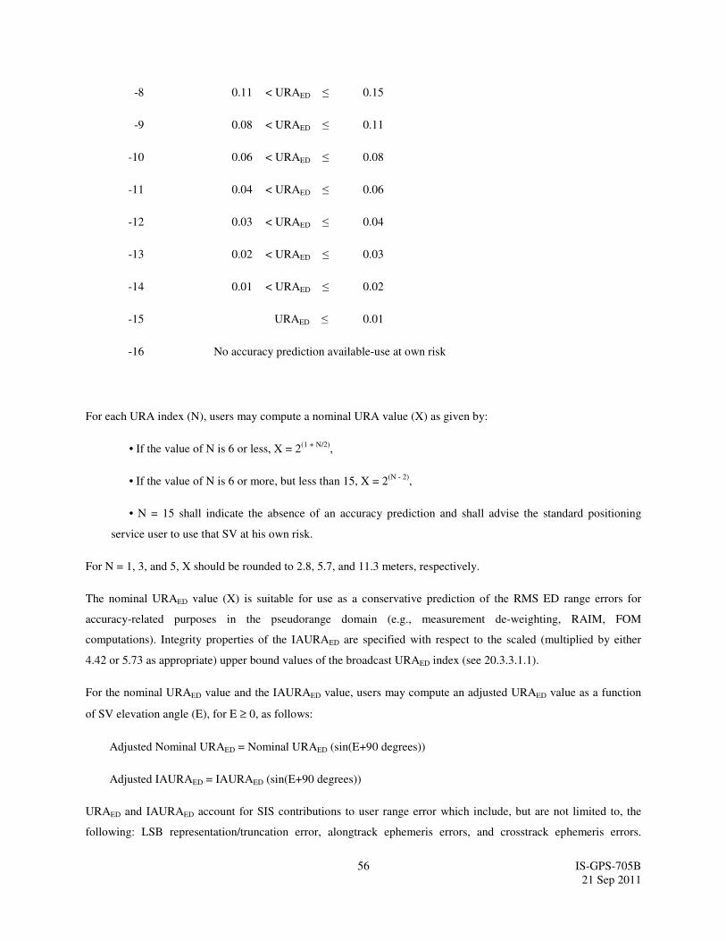
56 IS-GPS-705B
21 Sep 2011
-8 0.11 < URAED ≤ 0.15
-9 0.08 < URAED ≤ 0.11
-10 0.06 < URAED ≤ 0.08
-11 0.04 < URAED ≤ 0.06
-12 0.03 < URAED ≤ 0.04
-13 0.02 < URAED ≤ 0.03
-14 0.01 < URAED ≤ 0.02
-15 URAED ≤ 0.01
-16 No accuracy prediction available-use at own risk
For each URA index (N), users may compute a nominal URA value (X) as given by:
• If the value of N is 6 or less, X = 2(1 + N/2)
,
• If the value of N is 6 or more, but less than 15, X = 2(N - 2)
,
• N = 15 shall indicate the absence of an accuracy prediction and shall advise the standard positioning
service user to use that SV at his own risk.
For N = 1, 3, and 5, X should be rounded to 2.8, 5.7, and 11.3 meters, respectively.
The nominal URAED value (X) is suitable for use as a conservative prediction of the RMS ED range errors for
accuracy-related purposes in the pseudorange domain (e.g., measurement de-weighting, RAIM, FOM
computations). Integrity properties of the IAURAED are specified with respect to the scaled (multiplied by either
4.42 or 5.73 as appropriate) upper bound values of the broadcast URAED index (see 20.3.3.1.1).
For the nominal URAED value and the IAURAED value, users may compute an adjusted URAED value as a function
of SV elevation angle (E), for E ≥ 0, as follows:
Adjusted Nominal URAED = Nominal URAED (sin(E+90 degrees))
Adjusted IAURAED = IAURAED (sin(E+90 degrees))
URAED and IAURAED account for SIS contributions to user range error which include, but are not limited to, the
following: LSB representation/truncation error, alongtrack ephemeris errors, and crosstrack ephemeris errors.

57 IS-GPS-705B
21 Sep 2011
URAED and IAURAED do not account for user range error contributions due to the inaccuracy of the broadcast
ionospheric data parameters used in the single-frequency ionospheric model or for other atmospheric effects.
20.3.3.1.2 Message Types 10 and 11 Ephemeris Parameter Characteristics. For each ephemeris parameter contained
in message types 10 and 11, the number of bits, the scale factor of the least significant bit (LSB) (which is the last
bit received), the range, and the units are as specified in Table 20-I. See Figures 20-1 and 20-2 for complete bit
allocation in message types 10 and 11.
20.3.3.1.3 User Algorithm for Determination of SV Position. The user shall compute the ECEF coordinates of
position for the SV’s antenna phase center (APC) utilizing a variation of the equations shown in Table 20-II. The
ephemeris parameters are Keplerian in appearance; the values of these parameters, however, are produced by the CS
(Block IIF) or the SV (GPS III) via a least squares curve fit of the predicted ephemeris of the SV APC (time-
position quadruples; t, x, y, z expressed in ECEF coordinates). Particulars concerning the applicable coordinate
system are given in Sections 20.3.3.4.3.3 and 20.3.3.4.3.4 of IS-GPS-200.
The sensitivity of the SV’s position to small perturbations in most ephemeris parameters is extreme. The sensitivity
of position to the parameters A, Crc-n, and Crs-n is about one meter/meter. The sensitivity of position to the angular
parameters is on the order of 108 meters/semi-circle, and to the angular rate parameters is on the order of 10
12
meters/semi-circle/second. Because of this extreme sensitivity to angular perturbations, the value of π used in the
curve fit is given here. π is a mathematical constant, the ratio of a circle’s circumference to its diameter. Here π is
taken as 3.1415926535898.
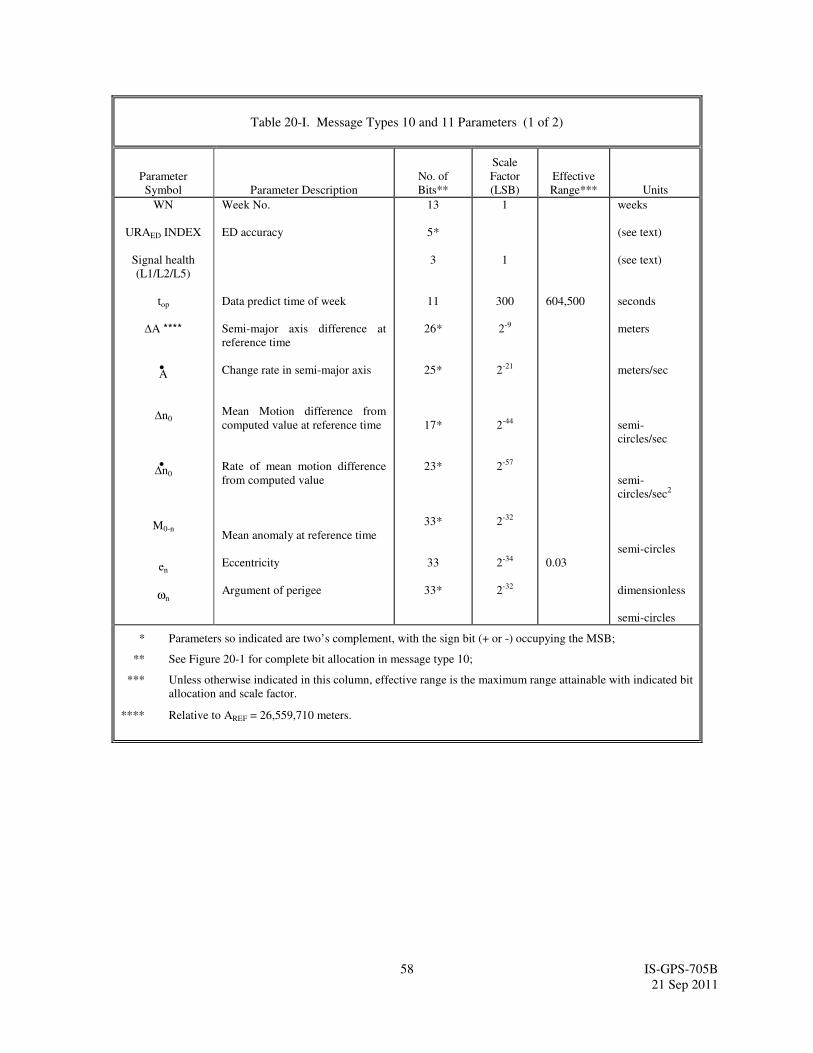
58 IS-GPS-705B
21 Sep 2011
Table 20-I. Message Types 10 and 11 Parameters (1 of 2)
Parameter
Symbol Parameter Description
No. of
Bits**
Scale
Factor
(LSB)
Effective
Range*** Units
WN
URAED INDEX
Signal health
(L1/L2/L5)
top
∆A ****
A
∆n0
∆n0
M0-n
en
ωn
Week No.
ED accuracy
Data predict time of week
Semi-major axis difference at
reference time
Change rate in semi-major axis
Mean Motion difference from
computed value at reference time
Rate of mean motion difference
from computed value
Mean anomaly at reference time
Eccentricity
Argument of perigee
13
5*
3
11
26*
25*
17*
23*
33*
33
33*
1
1
300
2-9
2-21
2-44
2-57
2-32
2-34
2-32
604,500
0.03
weeks
(see text)
(see text)
seconds
meters
meters/sec
semi-
circles/sec
semi-
circles/sec2
semi-circles
dimensionless
semi-circles
* Parameters so indicated are two’s complement, with the sign bit (+ or -) occupying the MSB;
** See Figure 20-1 for complete bit allocation in message type 10;
*** Unless otherwise indicated in this column, effective range is the maximum range attainable with indicated bit
allocation and scale factor.
**** Relative to AREF = 26,559,710 meters.
•
•
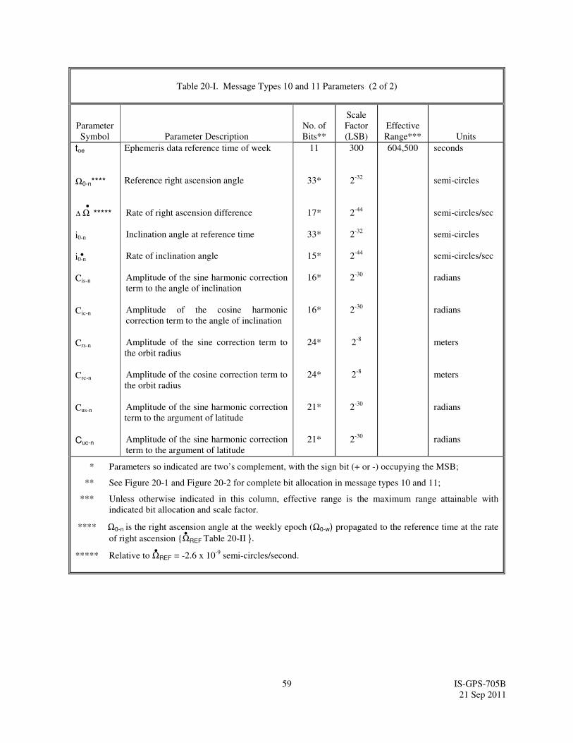
59 IS-GPS-705B
21 Sep 2011
Table 20-I. Message Types 10 and 11 Parameters (2 of 2)
Parameter
Symbol Parameter Description
No. of
Bits**
Scale
Factor
(LSB)
Effective
Range*** Units
toe
Ω0-n**** ***** i0-n
i0-n
Cis-n
Cic-n
Crs-n
Crc-n
Cus-n
Cuc-n
Ephemeris data reference time of week
Reference right ascension angle
Rate of right ascension difference
Inclination angle at reference time
Rate of inclination angle
Amplitude of the sine harmonic correction
term to the angle of inclination
Amplitude of the cosine harmonic
correction term to the angle of inclination
Amplitude of the sine correction term to
the orbit radius
Amplitude of the cosine correction term to
the orbit radius
Amplitude of the sine harmonic correction
term to the argument of latitude
Amplitude of the sine harmonic correction
term to the argument of latitude
11
33*
17*
33*
15*
16*
16*
24*
24*
21*
21*
300
2-32
2-44
2-32
2-44
2-30
2-30
2-8
2-8
2-30
2-30
604,500 seconds
semi-circles
semi-circles/sec
semi-circles
semi-circles/sec
radians
radians
meters
meters
radians
radians
* Parameters so indicated are two’s complement, with the sign bit (+ or -) occupying the MSB;
** See Figure 20-1 and Figure 20-2 for complete bit allocation in message types 10 and 11;
*** Unless otherwise indicated in this column, effective range is the maximum range attainable with
indicated bit allocation and scale factor.
**** Ω0-n is the right ascension angle at the weekly epoch (Ω0-w) propagated to the reference time at the rate
of right ascension ΩREF Table 20-II .
***** Relative to ΩREF = -2.6 x 10⁻⁹
semi-circles/second.
∆ Ω•
•
•
•
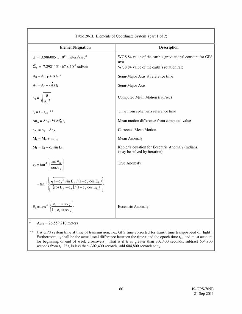
60 IS-GPS-705B
21 Sep 2011
Table 20-II. Elements of Coordinate System (part 1 of 2)
Element/Equation Description
µ = 3.986005 x 10¹⁴
meters3/sec
2
Ωe = 7.2921151467 x 10⁻⁵
rad/sec
A0 = AREF + ∆A *
Ak = A0 + (A) tk
n0 = 3
0A
µ
tk = t – toe **
∆nA = ∆n0 +½ ∆n0 tk
nA = n0 + ∆nA
Mk = M0 + nA tk
Mk = Ek – en sin Ek
νk = tan-1
ν
ν
k
k
cos
sin
= tan-1
( )
( ) ( )
−−
−−
knnk
knk2
n
E cos e 1 / e E cos
E cos e 1 / E sin e 1
Ek = cos-1
ν+
ν+
kn
kn
cose1
cose
WGS 84 value of the earth’s gravitational constant for GPS
user
WGS 84 value of the earth’s rotation rate
Semi-Major Axis at reference time
Semi-Major Axis
Computed Mean Motion (rad/sec)
Time from ephemeris reference time
Mean motion difference from computed value
Corrected Mean Motion
Mean Anomaly
Kepler’s equation for Eccentric Anomaly (radians)
(may be solved by iteration)
True Anomaly
Eccentric Anomaly
* AREF = 26,559,710 meters
** t is GPS system time at time of transmission, i.e., GPS time corrected for transit time (range/speed of light).
Furthermore, tk shall be the actual total difference between the time t and the epoch time toe, and must account
for beginning or end of week crossovers. That is if tk is greater than 302,400 seconds, subtract 604,800
seconds from tk. If tk is less than -302,400 seconds, add 604,800 seconds to tk.
•
•
•
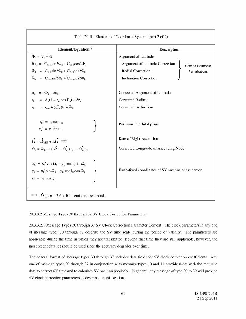
61 IS-GPS-705B
21 Sep 2011
Table 20-II. Elements of Coordinate System (part 2 of 2)
Element/Equation * Description
Φk = νk + ωn
δuk = Cus-nsin2Φk + Cuc-ncos2Φk
δrk = Crs-nsin2Φk + Crc-ncos2Φk
δik = Cis-nsin2Φk + Cic-ncos2Φk
uk = Φk + δuk
rk = Ak(1 – en cos Ek) + δrk
ik = io-n + (io-n )tk + δik
xk' = rk cos uk
yk' = rk sin uk
Ω = ΩREF + ∆Ω ***
Ωk = Ω0-n + ( Ω − Ωe ) tk – Ωe toe
xk = xk' cos Ωk − yk' cos ik sin Ωk
yk = xk' sin Ωk + yk' cos ik cos Ωk
zk = yk' sin ik
Argument of Latitude
Argument of Latitude Correction
Radial Correction
Inclination Correction
Corrected Argument of Latitude
Corrected Radius
Corrected Inclination
Positions in orbital plane
Rate of Right Ascension
Corrected Longitude of Ascending Node
Earth-fixed coordinates of SV antenna phase center
*** ΩREF = −2.6 x 10⁻⁹
semi-circles/second.
20.3.3.2 Message Types 30 through 37 SV Clock Correction Parameters.
20.3.3.2.1 Message Types 30 through 37 SV Clock Correction Parameter Content. The clock parameters in any one
of message types 30 through 37 describe the SV time scale during the period of validity. The parameters are
applicable during the time in which they are transmitted. Beyond that time they are still applicable, however, the
most recent data set should be used since the accuracy degrades over time.
The general format of message types 30 through 37 includes data fields for SV clock correction coefficients. Any
one of message types 30 through 37 in conjunction with message types 10 and 11 provide users with the requisite
data to correct SV time and to calculate SV position precisely. In general, any message of type 30 to 39 will provide
SV clock correction parameters as described in this section.
Second Harmonic
Perturbations
• • •
• • •
•
•

62 IS-GPS-705B
21 Sep 2011
20.3.3.2.1.1 SV Clock Correction. Any one of message types 30 through 37, Figure 20-3 through Figure 20-10,
contains the parameters needed by the users for apparent SV clock correction. Bits 61 to 71 contain toc, clock data
reference time of week. Bits 72 to 127 contain SV clock correction coefficients. The related algorithm is given in
paragraph 20.3.3.2.3.
20.3.3.2.1.2 Data Predict Time of Week. Bits 39 through 49 of message types 30 through 37 shall contain the data
predict time of week (top). The top term provides the epoch time of week of the state estimate utilized for the
prediction of SV clock correction coefficients.
20.3.3.2.2 Clock Parameter Characteristics. The number of bits, the scale factors of the LSB (which is the last bit
received), the range, and the units of clock correction parameters shall be as specified in Table 20-III.
20.3.3.2.3 User Algorithms for SV Clock Correction Data. The algorithms defined in paragraph 20.3.3.3.3.1 of IS-
GPS-200 allow all users to correct the code phase time received from the SV with respect to both SV code phase
offset and relativistic effects. However, since the SV clock corrections of equations in paragraph 20.3.3.3.3.1 of IS-
GPS-200 are estimated by the CS using dual frequency L1 and L2 P(Y) code measurements, the single-frequency
L5 user and the dual-frequency L1 and L5, and L2 and L5 users must apply additional terms to the SV clock
corrections equations. These terms are described in paragraph 20.3.3.3.1.
Table 20-III. Clock Correction and Accuracy Parameters
Parameter
Symbol Parameter Description
No. of
Bits**
Scale
Factor
(LSB)
Effective
Range***
Units
toc
URANED Index
URANED1 Index
URANED2 Index
af2-n
af1-n
af0-n
Clock Data Reference Time of Week
NED Accuracy Index
NED Accuracy Change Index
NED Accuracy Change Rate Index
SV Clock Drift Rate Correction
Coefficient
SV Clock Drift Correction Coefficient
SV Clock Bias Correction Coefficient
11
5*
3
3
10*
20*
26*
300
2-60
2-48
2-35
604,500
seconds
(see text)
(see text)
(see text)
sec/sec2
sec/sec
seconds
* Parameters so indicated are two’s complement, with the sign bit (+ or -) occupying the MSB;
** See Figures 20-3 through 20-10 for complete bit allocation in message types 30 to 37;
*** Unless otherwise indicated in this column, effective range is the maximum range attainable with
indicated bit allocation and scale factor.
63 IS-GPS-705B
21 Sep 2011
20.3.3.2.4 Non-Elevation-Dependent (NED) Accuracy Estimates. Bits 50 through 54, and 55 through 57, and 58
through 60 of message types 30 through 37 shall contain the non-elevation-dependent (NED) component URANED0
Index,URANED1 Index, and URANED2 Index, respectively, of the SV (reference paragraph 6.2.1) for the unauthorized
user. The following equations together with the broadcast URANED0 Index, URANED1 Index, and URANED2 Index
shall give the clock-related user range accuracy of IAURANED over the current clock/ephemeris fit interval. While
the actual NED-related URA may vary over the satellite footprint, the IAURANED calculated using the parameters in
message type 10 at each instant during the current clock/ephemeris fit interval shall bound the maximum IAURANED
expected for the worst-case location within the satellite footprint at that instant.
The user shall calculate the NED-related URA with the equation (in meters);
IAURANED = URANED0 + URANED1 (t - top + 604,800*(WN - WNop))
for t - top + 604800*(WN - WNop) ≤ 93,600 seconds
IAURANED = URANED0 + URANED1*(t - top + 604,800*(WN - WNop)) + URANED2*(t - top + 60,4800*(WN -
WNop) - 93,600)2
for t - top + 604,800*(WN - WNop) > 93,600 seconds
where
t is the GPS system time
WNop -- Data Predict Week Number, identifying the GPS week to which the top term refers. See Section IS-200,
Section 20.3.4.6.4.
The CS shall derive URANED0, URANED1, and URANED2 indexes which, when used together in the above equations,
results in the minimum IAURANED that is greater than the predicted IAURANED during the/ephemeris fit interval.
The user shall use the broadcast URANED0 index to derive the URANED0 value. The URANED0 index is a signed,
two’s complement integer in the range of +15 to -16 and has the following relationship to the URANED0 value:
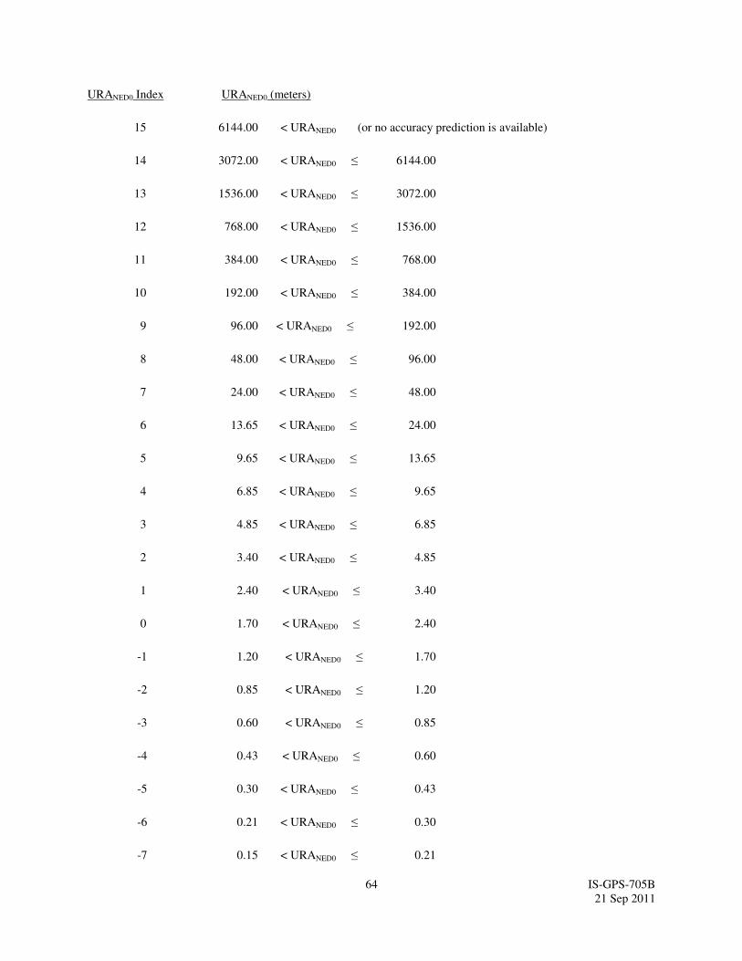
64 IS-GPS-705B
21 Sep 2011
URANED0 Index URANED0 (meters)
15 6144.00 < URANED0 (or no accuracy prediction is available)
14 3072.00 < URANED0 ≤ 6144.00
13 1536.00 < URANED0 ≤ 3072.00
12 768.00 < URANED0 ≤ 1536.00
11 384.00 < URANED0 ≤ 768.00
10 192.00 < URANED0 ≤ 384.00
9 96.00 < URANED0 ≤ 192.00
8 48.00 < URANED0 ≤ 96.00
7 24.00 < URANED0 ≤ 48.00
6 13.65 < URANED0 ≤ 24.00
5 9.65 < URANED0 ≤ 13.65
4 6.85 < URANED0 ≤ 9.65
3 4.85 < URANED0 ≤ 6.85
2 3.40 < URANED0 ≤ 4.85
1 2.40 < URANED0 ≤ 3.40
0 1.70 < URANED0 ≤ 2.40
-1 1.20 < URANED0 ≤ 1.70
-2 0.85 < URANED0 ≤ 1.20
-3 0.60 < URANED0 ≤ 0.85
-4 0.43 < URANED0 ≤ 0.60
-5 0.30 < URANED0 ≤ 0.43
-6 0.21 < URANED0 ≤ 0.30
-7 0.15 < URANED0 ≤ 0.21

65 IS-GPS-705B
21 Sep 2011
-8 0.11 < URANED0 ≤ 0.15
-9 0.08 < URANED0 ≤ 0.11
-10 0.06 < URANED0 ≤ 0.08
-11 0.04 < URANED0 ≤ 0.06
-12 0.03 < URANED0 ≤ 0.04
-13 0.02 < URANED0 ≤ 0.03
-14 0.01 < URANED0 ≤ 0.02
-15 URANED0 ≤ 0.01
-16 No accuracy prediction available-use at own risk
Integrity properties of the URA are specified with respect to the upper bound values of the URA index (see
20.3.3.1.1).
For each URANED0 index (N), users may compute a nominal URANED0 value (X) as given by:
• If the value of N is 6 or less, but more than -16, X = 2(1 + N/2)
,
• If the value of N is 6 or more, but less than 15, X = 2(N - 2)
,
• N = -16 or N = 15 shall indicate the absence of an accuracy prediction and shall advise the standard
positioning service user to use that SV at his own risk.
For N = 1, 3, and 5, X should be rounded to 2.8, 5.7, and 11.3 meters, respectively.
The nominal URANED0 value (X) shall be suitable for use as a conservative prediction of the RMS NED range errors
for accuracy-related purposes in the pseudorange domain (e.g., measurement de-weighting RAIM, FOM
computations). Integrity properties of the IAURANED are specified with respect to the scaled (multiplied by either
4.42 or 5.73 as appropriate) upper bound values of the URANED0 index, URANED1 index, and URANED2 index (see
20.3.3.1.1).
URANED0 accounts for zeroth order SIS contributions to user range error which include, but are not limited to, the
following: LSB representation/truncation error; the net effect of clock correction polynomial error and code phase
error in the transmitted signal for single-frequency L1C/A or single-frequency L2C users who correct the code phase
as described in Section 20.3.3.3.1.1.1; the net effect of clock parameter, code phase, and inter-signal correction error
for dual-frequency L1/L2 and L1/L5 users who correct for group delay and ionospheric effects as described in
Section 20.3.3.3.1.1.2; radial ephemeris error; anisotropic antenna errors; and signal deformation error. URANED
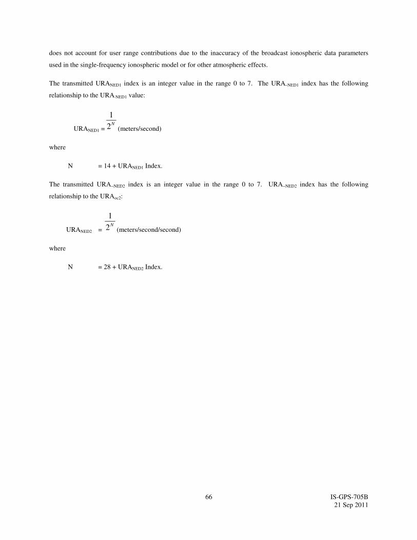
66 IS-GPS-705B
21 Sep 2011
does not account for user range contributions due to the inaccuracy of the broadcast ionospheric data parameters
used in the single-frequency ionospheric model or for other atmospheric effects.
The transmitted URANED1 index is an integer value in the range 0 to 7. The URA NED1 index has the following
relationship to the URA NED1 value:
URANED1 =N2
1
(meters/second)
where
N = 14 + URANED1 Index.
The transmitted URA NED2 index is an integer value in the range 0 to 7. URA NED2 index has the following
relationship to the URAoc2:
URANED2 = N2
1
(meters/second/second)
where
N = 28 + URANED2 Index.

67 IS-GPS-705B
21 Sep 2011
20.3.3.3 Message Type 30 Ionospheric and Group Delay Correction Parameters.
20.3.3.3.1 Message Type 30 Ionospheric and Group Delay Correction Parameter Content. Message type 30
provides SV clock correction parameters (ref. Section 20.3.3.2) and ionospheric and group delay correction
parameters. Bits 128 through 192 of message type 30 provide the group delay differential correction terms for L1,
L2, and L5 signal users. Bits 193 through 256 provide the ionospheric correction parameters for single frequency
user. The following algorithms shall apply when interpreting the correction parameters in the message.
20.3.3.3.1.1 Estimated L1-L2 Group Delay Differential. The group delay differential correction terms, TGD,
ISCL1C/A, ISCL2C are contained in bits 128 through 166 of message type 30. See paragraph 30.3.3.3.1.1 of IS-GPS-
200. The bit lengths, scale factors, ranges, and units of these parameters are given in Table 20-IV. These group
delay differential correction terms are also used for the benefit of single frequency L5-I5 and L5-Q5 users and dual
frequency L1/L5 and L2/L5 users.
20.3.3.3.1.1.1 L1/L2 Inter-Signal Group Delay Differential Correction. See paragraph 30.3.3.3.1.1.1 of IS-GPS-
200.
20.3.3.3.1.2 Estimated L5 Group Delay Differential. The group delay differential correction terms, TGD, ISCL5I5 and
ISCL5Q5, for the benefit of single frequency L5-I5 and L5-Q5 users and dual frequency L1/L5 and L2/L5 users are
contained in bits 128 through 140 and 167 through 192 of message type 30 (see Figure 20-3 for complete bit
allocation). The bit lengths, scale factors, ranges, and units of these parameters are given in Table 20-IV. The bit
string of “1000000000000” shall indicate that the group delay value is not available. The related algorithms are
given in paragraphs 20.3.3.3.1.2.1, 20.3.3.3.1.2.2, and 20.3.3.3.1.2.3.

68 IS-GPS-705B
21 Sep 2011
Table 20-IV. Group Delay Differential Parameters ****
Parameter
No. of
Bits**
Scale Factor
(LSB)
Effective
Range***
Units
TGD
ISCL1C/A
ISCL2C
ISCL5I5
ISCL5Q5
13*
13*
13*
13*
13*
2-35
2-35
2-35
2-35
2-35
seconds
seconds
seconds
seconds
seconds
* Parameters so indicated are two’s complement with the sign bit (+ or -) occupying the MSB;
** See Figure 20-3 for complete bit allocation in message type 30;
*** Effective range is the maximum range attainable with indicated bit allocation and scale factor;
**** The bit string of “1000000000000” will indicate that the group delay value is not available.
20.3.3.3.1.2.1 L1/L5 Inter-Signal Correction. The L5 correction terms, TGD, ISCL5I5 and ISCL5Q5 are provided by the
CS to account for the effect of inter-signal biases between L1 P(Y) and L2 P(Y), L1 P(Y) and L5 I5, and between
L1 P(Y) and L5 Q5, respectively. These values are initially based on measurements made by the SV contractor
during SV manufacture. The values of TGD and ISC’s for each SV may be subsequently updated to reflect the actual
on-orbit group delay differential. For maximum accuracy, the single frequency L5 I5 user must use the correction
terms to make further modifications to the code phase offset in paragraph 20.3.3.3.3.1 of IS-GPS-200 with the
equation:
(∆tSV)L5I5 = ∆tSV − TGD + ISCL5I5
where TGD (see paragraph 20.3.3.3.3.2 of IS-GPS-200) and ISCL5I5 (described in paragraph 20.3.3.3.1.2) are provided
to the user as message type 30 data. For maximum accuracy, the single frequency L5 Q5 user must use the
correction terms to make further modifications to the code phase offset given by:
(∆tSV)L5Q5 = ∆tSV − TGD + ISCL5Q5
where ISCL5Q5 (described in paragraph 20.3.3.3.1.2) is provided to the user as message type 30 data.
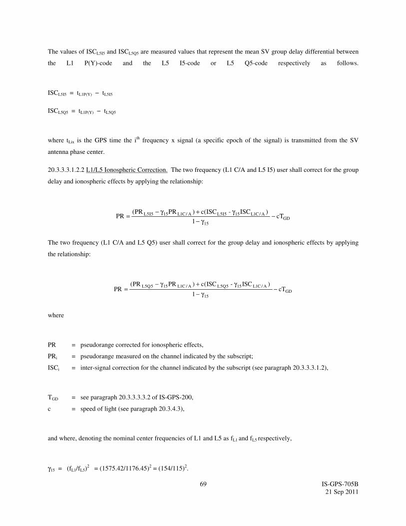
69 IS-GPS-705B
21 Sep 2011
The values of ISCL5I5 and ISCL5Q5 are measured values that represent the mean SV group delay differential between
the L1 P(Y)-code and the L5 I5-code or L5 Q5-code respectively as follows.
ISCL5I5 = tL1P(Y) − tL5I5
ISCL5Q5 = tL1P(Y) − tL5Q5
where tLix is the GPS time the ith
frequency x signal (a specific epoch of the signal) is transmitted from the SV
antenna phase center.
20.3.3.3.1.2.2 L1/L5 Ionospheric Correction. The two frequency (L1 C/A and L5 I5) user shall correct for the group
delay and ionospheric effects by applying the relationship:
GD15
A/C1L155I5LA/C1L155I5L cT1
)ISC -ISC(c)PRPR(PR −
γ−
γ+γ−=
The two frequency (L1 C/A and L5 Q5) user shall correct for the group delay and ionospheric effects by applying
the relationship:
GD15
A/C1L155Q5LA/C1L155Q5LcT
1
)ISC -ISC(c)PRPR(PR −
γ−
γ+γ−=
where
PR = pseudorange corrected for ionospheric effects,
PRi = pseudorange measured on the channel indicated by the subscript;
ISCi = inter-signal correction for the channel indicated by the subscript (see paragraph 20.3.3.3.1.2),
TGD = see paragraph 20.3.3.3.3.2 of IS-GPS-200,
c = speed of light (see paragraph 20.3.4.3),
and where, denoting the nominal center frequencies of L1 and L5 as fL1 and fL5 respectively,
γ15 = (fL1/fL5)2 = (1575.42/1176.45)
2 = (154/115)
2.
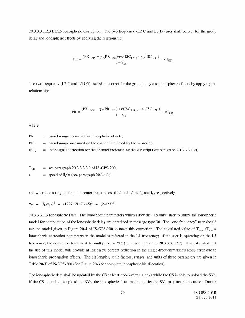
70 IS-GPS-705B
21 Sep 2011
20.3.3.3.1.2.3 L2/L5 Ionospheric Correction. The two frequency (L2 C and L5 I5) user shall correct for the group
delay and ionospheric effects by applying the relationship:
GD25
C2L255I5LC2L255I5L cT1
)ISC -ISC(c)PRPR(PR −
γ−
γ+γ−=
The two frequency (L2 C and L5 Q5) user shall correct for the group delay and ionospheric effects by applying the
relationship:
GD25
C2L255Q5LC2L255Q5LcT
1
)ISC -ISC(c)PRPR(PR −
γ−
γ+γ−=
where
PR = pseudorange corrected for ionospheric effects,
PRi = pseudorange measured on the channel indicated by the subscript,
ISCi = inter-signal correction for the channel indicated by the subscript (see paragraph 20.3.3.3.1.2),
TGD = see paragraph 20.3.3.3.3.2 of IS-GPS-200,
c = speed of light (see paragraph 20.3.4.3).
and where, denoting the nominal center frequencies of L2 and L5 as fL2 and fL5 respectively.
γ25 = (fL2/fL5)2 = (1227.6/1176.45)
2 = (24/23)
2
20.3.3.3.1.3 Ionospheric Data. The ionospheric parameters which allow the “L5 only” user to utilize the ionospheric
model for computation of the ionospheric delay are contained in message type 30. The “one frequency” user should
use the model given in Figure 20-4 of IS-GPS-200 to make this correction. The calculated value of Tiono (Tiono =
ionospheric correction parameter) in the model is referred to the L1 frequency; if the user is operating on the L5
frequency, the correction term must be multiplied by γ15 (reference paragraph 20.3.3.3.1.2.2). It is estimated that
the use of this model will provide at least a 50 percent reduction in the single-frequency user’s RMS error due to
ionospheric propagation effects. The bit lengths, scale factors, ranges, and units of these parameters are given in
Table 20-X of IS-GPS-200 (See Figure 20-3 for complete ionospheric bit allocation).
The ionospheric data shall be updated by the CS at least once every six days while the CS is able to upload the SVs.
If the CS is unable to upload the SVs, the ionospheric data transmitted by the SVs may not be accurate. During
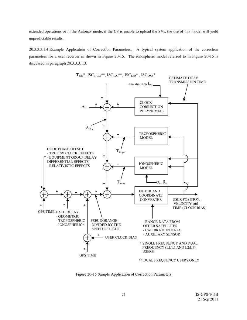
71 IS-GPS-705B
21 Sep 2011
extended operations or in the Autonav mode, if the CS is unable to upload the SVs, the use of this model will yield
unpredictable results.
20.3.3.3.1.4 Example Application of Correction Parameters. A typical system application of the correction
parameters for a user receiver is shown in Figure 20-15. The ionospheric model referred to in Figure 20-15 is
discussed in paragraph 20.3.3.3.1.3.
CLOCK
CORRECTION
POLYNOMIAL
TROPOSPHERIC MODEL
IONOSPHERIC
MODEL
FILTER AND
COORDINATE
CONVERTER
ESTIMATE OF SV TRANSMISSION TIME
Tiono
USER POSITION,
VELOCITY and
TIME (CLOCK BIAS)
- RANGE DATA FROM
OTHER SATELLITES
- CALIBRATION DATA
- AUXILIARY SENSOR USER CLOCK BIAS
PSEUDORANGE
DIVIDED BY THE
SPEED OF LIGHT
PATH DELAY
- GEOMETRIC
- TROPOSPHERIC
- IONOSPHERIC*
GPS TIME
GPS TIME
CODE PHASE OFFSET
- TRUE SV CLOCK EFFECTS
- EQUIPMENT GROUP DELAY
DIFFERENTIAL EFFECTS
- RELATIVISTIC EFFECTS
* SINGLE FREQUENCY AND DUAL
FREQUENCY (L1/L5 AND L2/L5) USERS
** DUAL FREQUENCY USERS ONLY
αn, βn
Ttropo
TGD*, ISCL1C/A**, ISCL2C**, ISCL5I5* , ISCL5Q5*
∆tr
∆tSV
af0, af1, af2, toc
Figure 20-15 Sample Application of Correction Parameters
72 IS-GPS-705B
21 Sep 2011
20.3.3.4 Message Types 31, 12 and 37 Almanac Parameters. The almanac parameters are provided in any one of
message types 31, 37, and 12. Message type 37 provides Midi almanac parameters and the reduced almanac
parameters are provided in either message type 31 or type 12. The SV shall broadcast both message types 31
(and/or 12) and 37. However, the reduced almanac parameters (i.e. message types 31 and/or 12) for the complete set
of SVs in the constellation will be broadcast by a SV using shorter duration of time compared to the broadcast of the
complete set of Midi almanac parameters (i.e. message type 37). The parameters are defined below, followed by
material pertinent to the use of the data.
20.3.3.4.1 Almanac Reference Week. Bits 39 through 51 of message types 12, and bits 128 through 140 of message
type 31 and 37 shall indicate the number of the week (WNa-n) to which the almanac reference time (toa) is referenced
(see paragraph 20.3.3.4.2). The WNa-n term consists of 13 bits which shall be a modulo-8192 binary representation
of the GPS week number (see paragraph 6.2.4) to which the toa is referenced. Bits 52 through 59 of message types
12, and bits 141 to 148 of message types 31 and 37 shall contain the value of toa, which is referenced to this WNa-n.
20.3.3.4.2 Almanac Reference Time. See paragraph 20.3.3.5.2.2 of IS-GPS-200.
20.3.3.4.3 SV PRN Number. Bits 149 through 154 of message type 37 and bits 1 through 6 in each packet of
reduced almanac shall specify PRN number of the SV whose almanac or reduced almanac, respectively, is provided
in the message or in the packet.
20.3.3.4.4 Signal Health (L1/L2/L5). The three, one-bit, health indication in bits 155, 156 and 157 of message type
37 and bits 29,30 and 31 of each packet of reduced almanac refers to the L1, L2, and L5 signals of the SV whose
PRN number is specified in the message or in the packet. For each health indicator, a “0” signifies that all
navigation data are okay and “1” signifies that some or all navigation data are bad. The predicted health data will be
updated at the time of upload when a new reduced almanac has been built by the CS. The transmitted health data
may not correspond to the actual health of the transmitting SV or other SVs in the constellation.
20.3.3.4.5 Midi Almanac Parameter Content. Message type 37, Figure 20-10, provides Midi almanac data for a SV
whose PRN number is specified in the message. The number of bits, the scale factor (LSB), the range, and the units
of the almanac parameters are given in Table 20-V. The user algorithm is essentially the same as the user algorithm
used for computing the precise ephemeris as specified in Table 20-IV of IS-GPS-200. Other parameters appearing
in the equations of Table 20-IV of IS-GPS-200, but not provided by the Midi almanac with the reference values, are
set to zero for SV position determination. See paragraph 20.3.3.5.2.3 of IS-GPS-200 for almanac time parameters.
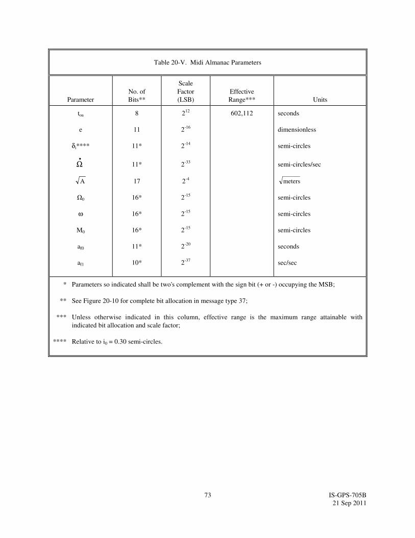
73 IS-GPS-705B
21 Sep 2011
Table 20-V. Midi Almanac Parameters
Parameter
No. of
Bits**
Scale
Factor
(LSB)
Effective
Range***
Units
toa
e
δi****
Ω
•
A
Ω0
ω
M0
af0
af1
8
11
11*
11*
17
16*
16*
16*
11*
10*
212
2-16
2-14
2-33
2-4
2-15
2-15
2-15
2-20
2-37
602,112
seconds
dimensionless
semi-circles
semi-circles/sec
meters
semi-circles
semi-circles
semi-circles
seconds
sec/sec
* Parameters so indicated shall be two's complement with the sign bit (+ or -) occupying the MSB;
** See Figure 20-10 for complete bit allocation in message type 37;
*** Unless otherwise indicated in this column, effective range is the maximum range attainable with
indicated bit allocation and scale factor;
**** Relative to i0 = 0.30 semi-circles.

74 IS-GPS-705B
21 Sep 2011
20.3.3.4.6 Reduced Almanac Parameter Content. Message type 31, Figure 20-4, provides SV clock correction
parameters (ref. Section 20.3.3.2) and reduced almanac data packets for 4 SVs. Message type 12, Figure 20-11
contains reduced almanac data packets for 7 SVs.
20.3.3.4.6.1 Reduced Almanac Data. Message types 31 or 12 contain reduced almanac data and SV health words
for SVs in the constellation. The reduced almanac data of a SV is broadcast in a packet 31 bits long, as described in
Figure 20-16. The reduced almanac data are a subset of the almanac data which provide less precise ephemeris.
The reduced almanac data values are provided relative to pre-specified reference values. The number of bits, the
scale factor (LSB), the ranges, and the units of the reduced almanac parameters are given in Table 20-VI. The
algorithms and other material related to the use of the reduced almanac data are given in Section 20.3.3.4.6.2.
The reduced almanac parameters shall be updated by the CS at least once every 3 days while the CS is able to
upload the SVs. If the CS is unable to upload the SVs, the accuracy of the reduced almanac parameters transmitted
by the SVs will degrade over time.
20.3.3.4.6.2 Reduced Almanac Packet. The following shall apply when interpreting the data provided in each
packet of reduced almanac (see Figure 20-16).
20.3.3.4.6.2.1 Reduced Almanac. The reduced almanac data is provided in bits 7 through 28 of each packet. The
data from a packet along with the reference values (see Table 20-VI) provide ephemeris with further reduced
precision. The user algorithm is essentially the same as the user algorithm used for computing the precise ephemeris
from the parameters of the message types 10 and 11 (see paragraph 20.3.3.1.3 and Table 20-II). Other parameters
appearing in the equations of Table 20-II, but not provided by the reduced almanac with the reference values, are set
to zero for SV position determination.
Figure 20-16. Reduced Almanac Packet Content
31 BITS
PRNa
δA
Ω0
Φ0
L1 HEALTH
L2 HEALTH
L5 HEALTH
1 7 15 22 31 30 29
* See Figures 20-4 and 20-11 for complete bit allocation in the respective messages.

75 IS-GPS-705B
21 Sep 2011
Table 20-VI. Reduced Almanac Parameters
Parameter***** No. of Bits Scale Factor (LSB) Effective Range **
Units
δA ***
Ω0
Φ0 ****
8 *
7 *
7 *
2+9
2-6
2-6
**
**
**
meters
semi-circles
semi-circles
* Parameters so indicated shall be two’s complement with the sign bit (+ or -) occupying the MSB;
** Effective range is the maximum range attainable with indicated bit allocation and scale factor;
*** Relative to Aref = 26,559,710 meters;
**** Φ0 = Argument of Latitude at Reference Time = M0 + ω;
***** Relative to following reference values:
e = 0
δi = +0.0056 semi-circles (i = 55 degrees)
Ω =-2.6 x 10⁻⁹
semi-circles/second
•

76 IS-GPS-705B
21 Sep 2011
20.3.3.5 Message Type 32 Earth Orientation Parameters (EOP). The earth orientation parameters are provided in
message type 32. The parameters are defined below, followed by material pertinent to the use of the data.
20.3.3.5.1 EOP Content. Message type 32, Figure 20-5, provides SV clock correction parameters (ref. Section
20.3.3.2) and earth orientation parameters. The EOP message provides users with parameters to construct the ECEF
and ECI coordinate transformation (a simple transformation method is defined in Section 20.3.3.4.3.3.2 of IS-GPS-
200). The number of bits, scale factors (LSBs), the ranges, and the units of all EOP fields of message type 32 are
given in Table 20-VII.
20.3.3.5.1.1 User Algorithm for Application of the EOP. The EOP fields in the message type 32 contain the EOP
data needed to construct the ECEF-to-ECI coordinate transformation. The user computes the ECEF position of the
SV antenna phase center using the equations shown in Table 20-II. The full coordinate transformation for
translating to the corresponding ECI SV antenna phase center position may be accomplished in accordance with the
computations detailed in Chapter 5 of IERS Technical Note 36: IERS Conventions (2010) and equations for UT1,
xp and yp as documented in Table 20-VIII. Figure 5.1 on page 73 of that document depicts the computational flow
starting from GCRS (Geocentric Celestial Reference System) to ITRS (International Terrestrial Reference System).
Ongoing WGS 84 re-adjustment at NGA and incorporating the 2010 IERS Conventions, are expected to bring Earth
based coordinate agreement to within 2 cm. In the context of the Conventions, the user may as a matter of
convenience choose to implement the transformation computations via either the Celestial Intermediate Origin
(CIO) based approach” or the “Equinox based approach”. The EOP parameters for ∆UT1 are to be applied
within the “Rotation to terrestrial system” process, and the parameters for xp and yp are applied in the “Rotation
for polar motion” process. Users are advised that the broadcast message type 32 EOP parameters already account
for zonal, diurnal and semidiurnal effects (described in Chapter 8 of the IERS Conventions (2010)), so these effects
should not be further applied by the user.
The relevant computations utilize elementary rotation matrices Ri(α), where α is a positive rotation about the ith-
axis ordinate, as follows:
( ) ( )
α − α α = α α α = − α α α α
1 0 0 cos( ) 0 sin( )
R 0 cos( ) sin ( ) , R 0 1 01 2
0 sin( ) cos( ) sin( ) 0 cos( )
( )
α α α = − α α
cos ( ) sin( ) 0
R sin( ) cos( ) 03
0 0 1

77 IS-GPS-705B
21 Sep 2011
The Inertial-to-Geodetic rotation matrix shall be calculated in accordance with the computations detailed in Chapter
5 of IERS Technical Note 36: IERS Conventions (2010) and equations for UT1, xp and yp as documented in Table
20-VIII.
Table 20-VII. Earth Orientation Parameters
Parameter Symbol Parameter Description
No. of
Bits**
Scale
Factor
(LSB)
Effective
Range***
Units
tEOP
PM_X †
PM_X
PM_Y ††
PM_Y
∆UT1 †††
∆UT1 †††
EOP Data Reference Time
X-Axis Polar Motion Value
at Reference Time.
X-Axis Polar Motion Drift at
Reference Time.
Y-Axis Polar Motion Value
at Reference Time.
Y-Axis Polar Motion Drift at
Reference Time.
UT1-UTC Difference at
Reference Time.
Rate of UT1-UTC
Difference at Reference
Time
16
21*
15*
21*
15*
31*
19*
24
2-20
2-21
2-20
2-21
2-24
2-25
604,784
1
7.8125 x 10⁻³
1
7.8125 x 10⁻³
64
7.8125 x 10⁻³
seconds
arc-seconds
arc-seconds/day
arc-seconds
arc-seconds/day
seconds
seconds/day
* Parameters so indicated are two’s complement, with the sign bit (+ or -) occupying the MSB;
** See Figure 20-5 for complete bit allocation in message type 32;
*** Unless otherwise indicated in this column, effective range is the maximum range attainable with
indicated bit allocation and scale factor.
†
Represents the predicted angular displacement of instantaneous Celestial Ephemeris Pole with respect to
semi-minor axis of the reference ellipsoid along Greenwich meridian.
††
Represents the predicted angular displacement of instantaneous Celestial Ephemeris Pole with respect to
semi-minor axis of the reference ellipsoid on a line directed 90° west of Greenwich meridian.
†††
With zonal tides restored.
•
•
•
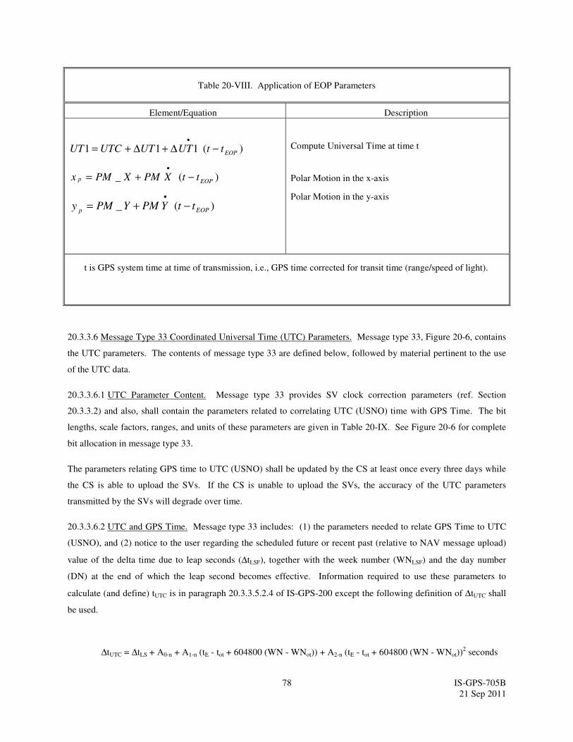
78 IS-GPS-705B
21 Sep 2011
Table 20-VIII. Application of EOP Parameters
Element/Equation Description
)(111 EOPttUTUTUTCUT −∆+∆+=•
)(_ EOPp ttXPMXPMx −+=•
)(_ EOPpttYPMYPMy −+=
•
Compute Universal Time at time t
Polar Motion in the x-axis
Polar Motion in the y-axis
t is GPS system time at time of transmission, i.e., GPS time corrected for transit time (range/speed of light).
20.3.3.6 Message Type 33 Coordinated Universal Time (UTC) Parameters. Message type 33, Figure 20-6, contains
the UTC parameters. The contents of message type 33 are defined below, followed by material pertinent to the use
of the UTC data.
20.3.3.6.1 UTC Parameter Content. Message type 33 provides SV clock correction parameters (ref. Section
20.3.3.2) and also, shall contain the parameters related to correlating UTC (USNO) time with GPS Time. The bit
lengths, scale factors, ranges, and units of these parameters are given in Table 20-IX. See Figure 20-6 for complete
bit allocation in message type 33.
The parameters relating GPS time to UTC (USNO) shall be updated by the CS at least once every three days while
the CS is able to upload the SVs. If the CS is unable to upload the SVs, the accuracy of the UTC parameters
transmitted by the SVs will degrade over time.
20.3.3.6.2 UTC and GPS Time. Message type 33 includes: (1) the parameters needed to relate GPS Time to UTC
(USNO), and (2) notice to the user regarding the scheduled future or recent past (relative to NAV message upload)
value of the delta time due to leap seconds (∆tLSF), together with the week number (WNLSF) and the day number
(DN) at the end of which the leap second becomes effective. Information required to use these parameters to
calculate (and define) tUTC is in paragraph 20.3.3.5.2.4 of IS-GPS-200 except the following definition of ∆tUTC shall
be used.
∆tUTC = ∆tLS + A0-n + A1-n (tE - tot + 604800 (WN - WNot)) + A2-n (tE - tot + 604800 (WN - WNot))2 seconds
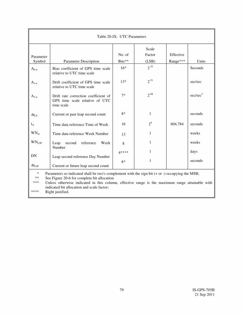
79 IS-GPS-705B
21 Sep 2011
Table 20-IX. UTC Parameters
Parameter
Symbol Parameter Description
No. of
Bits**
Scale
Factor
(LSB)
Effective
Range***
Units
A0-n
A1-n
A2-n
∆tLS
tot
WNot
WNLSF
DN
∆tLSF
Bias coefficient of GPS time scale
relative to UTC time scale
Drift coefficient of GPS time scale
relative to UTC time scale
Drift rate correction coefficient of
GPS time scale relative of UTC
time scale
Current or past leap second count
Time data reference Time of Week
Time data reference Week Number
Leap second reference Week
Number
Leap second reference Day Number
Current or future leap second count
16*
13*
7*
8*
16
13
8
4****
8*
2-35
2-51
2-68
1
24
1
1
1
1
604,784
Seconds
sec/sec
sec/sec2
seconds
seconds
weeks
weeks
days
seconds
* Parameters so indicated shall be two's complement with the sign bit (+ or -) occupying the MSB;
** See Figure 20-6 for complete bit allocation
*** Unless otherwise indicated in this column, effective range is the maximum range attainable with
indicated bit allocation and scale factor;
**** Right justified.

80 IS-GPS-705B
21 Sep 2011
20.3.3.7 Message Types 34, 13, and 14 Differential Correction Parameters. Differential Correction (DC) parameters
are provided either in message type 34, or in types 13 and 14. These parameters provide users with sets of
correction terms that apply to the clock and ephemeris data transmitted by other SVs. DC parameters are grouped in
packets, as described in the next sections. The availability of these message types is subject to the control and
determination of the CS.
20.3.3.7.1 Differential Correction Parameters Content. Message type 34 provides SV clock correction parameters
(ref. Section 20.3.3.2) and also, shall contain DC parameters that apply to the clock and ephemeris data transmitted
by another SV. One message type 34, Figure 20-7, shall contain 34 bits of clock differential correction (CDC)
parameters and 92 bits of ephemeris differential correction (EDC) parameters for one SV other than the transmitting
SV. Bit 150 of message type 34 shall be a DC Data Type indicator that indicates the data type for which the DC
parameters apply. Zero (0) signifies that the corrections apply to L5 CNAV data, D5(t), and one (1) signifies that the
corrections apply to NAV data, D(t), described in Appendix II of IS-GPS-200.
Message types 13 and 14 together also provide DC parameters. Message type 13, Figure 20-12, shall contain CDC
parameters applicable to 6 SVs and message type 14, Figure 20-13, shall contain EDC parameters applicable to 2
SVs. There shall be a DC Data Type indicator preceding each CDC or EDC packet. The content of an individual
data packet is depicted in Figure 20-17. The number of bits, scale factors (LSB), the ranges, and the units of all
fields in the DC packet are given in Table 20-X.

81 IS-GPS-705B
21 Sep 2011
20.3.3.7.2 DC Data Packet. Each DC data packet contains: corrections to SV clock polynomial coefficients
provided in any one of the message types 30 to 37 of the corresponding SV; corrections to quasi-Keplerian elements
referenced to tOD of the corresponding SV; User Differential Range Accuracy (UDRA) and UDRA indices that
enable users to estimate the accuracy obtained after corrections are applied. Each DC packet is made up of two
different segments. The first segment contains 34 bits for the CDC parameters and the second segment contains 92
bits of EDC parameters totaling 126 bits. The CDC and EDC parameters form an indivisible pair and users must
utilize CDC and EDC as a pair. Users must utilize CDC and EDC data pairs of the same top-D (top-D =DC data predict
time of week) and of the same tOD.
20.3.3.7.2.1 Differential Correction Data Predict Time of Week. The DC data predict time of week (top-D) provides
the epoch time of week, in increments of 300 seconds (i.e. five minutes), at which the prediction for the associated
DC data was performed.
20.3.3.7.2.2 Time of Differential Correction Data. The time of DC data, tOD, specifies the reference time of week, in
increments of 300 seconds (i.e., five minutes) relative to the GPS week, for the associated CDC and EDC data.
20.3.3.7.2.3 SV PRN Identification. The PRN ID of both CDC and EDC of Figure 20-17 identifies the satellite to
which the subject 126-bit differential correction packet data applies (by PRN code assignment). A value of all ones
“11111111” in any PRN ID field shall indicate that no DC data is contained in the remainder of the data block. In
this event, the remainder of the data block shall be filler bits, i.e., alternating ones and zeros beginning with one.
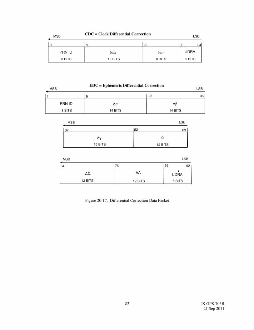
82 IS-GPS-705B
21 Sep 2011
Figure 20-17. Differential Correction Data Packet
CDC = Clock Differential Correction MSB LSB
1 9
EDC = Ephemeris Differential CorrectionMSB LSB
1 9
∆i.
12 BITS
12 BITS
23
PRN ID .
8 BITS
∆α .
14 BITS
36
∆β.
14 BITS
UDRA
. 5 BITS
δaf0
. 13 BITS
δaf1
. 8 BITS
5 BITS
63
PRN ID .
8 BITS
∆γ.
15 BITS
22 3430
MSB LSB
37 52
.
12 BITS
MSB LSB
∆Ω
64 76
∆A
88 92
UDRA•

83 IS-GPS-705B
21 Sep 2011
Table 20-X. Differential Correction Parameters
Parameter
Symbol Parameter Description
No. of
Bits**
Scale
Factor
(LSB)
Effective
Range***
Units
PRN ID
δaf0
δaf1
UDRA
∆α
∆β
∆γ
∆i
∆Ω
∆A
UDRA
SV Clock Bias Correction
SV Clock Drift Correction
User Differential Range
Accuracy Index.
Alpha Correction to Ephemeris
Parameters
Beta Correction to Ephemeris
Parameters
Gamma Correction to Ephemeris
Parameters
Angle of Inclination Correction
Angle of Right Ascension
Correction
Semi-Major Correction
Change Rate of User Differential
Range Accuracy Index
8
13*
8*
5*
14*
14*
15*
12*
12*
12*
5*
2-35
2-51
2-34
2-34
2-32
2-32
2-32
2-9
see text
seconds
seconds/second
see text
dimensionless
dimensionless
semi-circles
semi-circles
semi-circles
meters
see text
* Parameters so indicated are two’s complement, with the sign bit (+ or -) occupying the MSB;
** See Figures 20-7, 11 and 12 for complete bit allocation in message types 34, 13 and 14.
*** Unless otherwise indicated in this column, effective range is the maximum range attainable with indicated
bit allocation and scale factor.
•
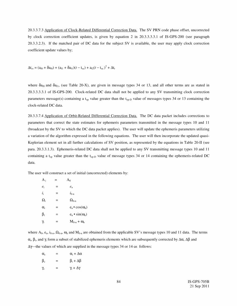
84 IS-GPS-705B
21 Sep 2011
20.3.3.7.3 Application of Clock-Related Differential Correction Data. The SV PRN code phase offset, uncorrected
by clock correction coefficient updates, is given by equation 2 in 20.3.3.3.3.1 of IS-GPS-200 (see paragraph
20.3.3.2.3). If the matched pair of DC data for the subject SV is available, the user may apply clock correction
coefficient update values by;
∆tsv = (af0 + δaf0) + (af1 + δaf1)(t − toc) + af2(t − toc )2 + ∆tr
where δaf0 and δaf1, (see Table 20-X), are given in message types 34 or 13, and all other terms are as stated in
20.3.3.3.3.1 of IS-GPS-200. Clock-related DC data shall not be applied to any SV transmitting clock correction
parameters message(s) containing a top value greater than the top-D value of messages types 34 or 13 containing the
clock-related DC data.
20.3.3.7.4 Application of Orbit-Related Differential Correction Data. The DC data packet includes corrections to
parameters that correct the state estimates for ephemeris parameters transmitted in the message types 10 and 11
(broadcast by the SV to which the DC data packet applies). The user will update the ephemeris parameters utilizing
a variation of the algorithm expressed in the following equations. The user will then incorporate the updated quasi-
Keplerian element set in all further calculations of SV position, as represented by the equations in Table 20-II (see
para. 20.3.3.1.3). Ephemeris-related DC data shall not be applied to any SV transmitting message types 10 and 11
containing a top value greater than the top-D value of message types 34 or 14 containing the ephemeris-related DC
data.
The user will construct a set of initial (uncorrected) elements by:
A i = A0
ei = en
ii = i0-n
Ωi = Ω0-n
αi = en • cos(ωn)
βi = en • sin(ωn)
γi = M0-n + ωn
where A0, en, i0-n, Ω0-n, ωn and M0-n are obtained from the applicable SV’s message types 10 and 11 data. The terms
αi, βi, and γi form a subset of stabilized ephemeris elements which are subsequently corrected by ∆α, ∆β and
∆γthe values of which are supplied in the message types 34 or 14-as follows:
αc = αi + ∆α
βc = βi + ∆β
γc = γi + ∆γ
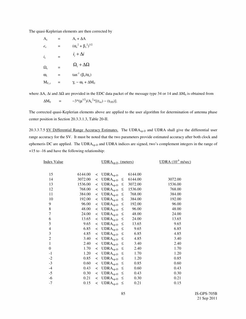
85 IS-GPS-705B
21 Sep 2011
The quasi-Keplerian elements are then corrected by
Ac = Ai + ∆A
ec = (αc2 + βc
2)
1/2
ic = iii ∆+
Ωc = ∆Ω+Ωi
ωc = tan-1
(βc/αc)
M0_c = γc − ωc + ∆M0
where ∆A, ∆i and ∆Ω are provided in the EDC data packet of the message type 34 or 14 and ∆M0 is obtained from
∆M0 = −3*(µ1/2)/Ac
2*[(toe) − (tOD)].
The corrected quasi-Keplerian elements above are applied to the user algorithm for determination of antenna phase
center position in Section 20.3.3.1.3, Table 20-II.
20.3.3.7.5 SV Differential Range Accuracy Estimates. The UDRAop-D and UDRA shall give the differential user
range accuracy for the SV. It must be noted that the two parameters provide estimated accuracy after both clock and
ephemeris DC are applied. The UDRAop-D and UDRA indices are signed, two’s complement integers in the range of
+15 to -16 and have the following relationship:
Index Value UDRAop-D (meters) UDRA (10-6
m/sec)
15 6144.00 < UDRAop-D 6144.00
14 3072.00 < UDRAop-D ≤ 6144.00 3072.00
13 1536.00 < UDRAop-D ≤ 3072.00 1536.00
12 768.00 < UDRAop-D ≤ 1536.00 768.00
11 384.00 < UDRAop-D ≤ 768.00 384.00
10 192.00 < UDRAop-D ≤ 384.00 192.00
9 96.00 < UDRAop-D ≤ 192.00 96.00
8 48.00 < UDRAop-D ≤ 96.00 48.00
7 24.00 < UDRAop-D ≤ 48.00 24.00
6 13.65 < UDRAop-D ≤ 24.00 13.65
5 9.65 < UDRAop-D ≤ 13.65 9.65
4 6.85 < UDRAop-D ≤ 9.65 6.85
3 4.85 < UDRAop-D ≤ 6.85 4.85
2 3.40 < UDRAop-D ≤ 4.85 3.40
1 2.40 < UDRAop-D ≤ 3.40 2.40
0 1.70 < UDRAop-D ≤ 2.40 1.70
-1 1.20 < UDRAop-D ≤ 1.70 1.20
-2 0.85 < UDRAop-D ≤ 1.20 0.85
-3 0.60 < UDRAop-D ≤ 0.85 0.60
-4 0.43 < UDRAop-D ≤ 0.60 0.43
-5 0.30 < UDRAop-D ≤ 0.43 0.30
-6 0.21 < UDRAop-D ≤ 0.30 0.21
-7 0.15 < UDRAop-D ≤ 0.21 0.15
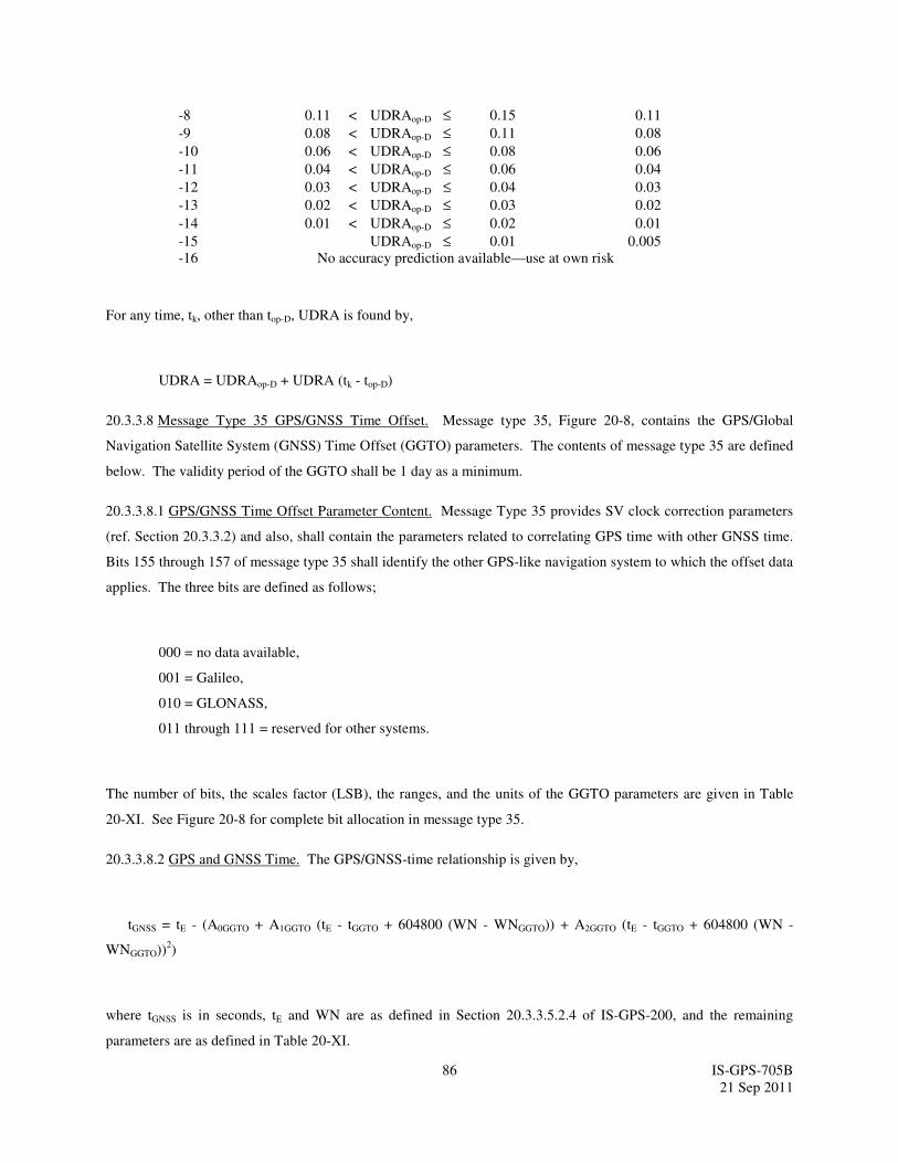
86 IS-GPS-705B
21 Sep 2011
-8 0.11 < UDRAop-D ≤ 0.15 0.11
-9 0.08 < UDRAop-D ≤ 0.11 0.08
-10 0.06 < UDRAop-D ≤ 0.08 0.06
-11 0.04 < UDRAop-D ≤ 0.06 0.04
-12 0.03 < UDRAop-D ≤ 0.04 0.03
-13 0.02 < UDRAop-D ≤ 0.03 0.02
-14 0.01 < UDRAop-D ≤ 0.02 0.01
-15 UDRAop-D ≤ 0.01 0.005
-16 No accuracy prediction available—use at own risk
For any time, tk, other than top-D, UDRA is found by,
UDRA = UDRAop-D + UDRA (tk - top-D)
20.3.3.8 Message Type 35 GPS/GNSS Time Offset. Message type 35, Figure 20-8, contains the GPS/Global
Navigation Satellite System (GNSS) Time Offset (GGTO) parameters. The contents of message type 35 are defined
below. The validity period of the GGTO shall be 1 day as a minimum.
20.3.3.8.1 GPS/GNSS Time Offset Parameter Content. Message Type 35 provides SV clock correction parameters
(ref. Section 20.3.3.2) and also, shall contain the parameters related to correlating GPS time with other GNSS time.
Bits 155 through 157 of message type 35 shall identify the other GPS-like navigation system to which the offset data
applies. The three bits are defined as follows;
000 = no data available,
001 = Galileo,
010 = GLONASS,
011 through 111 = reserved for other systems.
The number of bits, the scales factor (LSB), the ranges, and the units of the GGTO parameters are given in Table
20-XI. See Figure 20-8 for complete bit allocation in message type 35.
20.3.3.8.2 GPS and GNSS Time. The GPS/GNSS-time relationship is given by,
tGNSS = tE - (A0GGTO + A1GGTO (tE - tGGTO + 604800 (WN - WNGGTO)) + A2GGTO (tE - tGGTO + 604800 (WN -
WNGGTO))2)
where tGNSS is in seconds, tE and WN are as defined in Section 20.3.3.5.2.4 of IS-GPS-200, and the remaining
parameters are as defined in Table 20-XI.
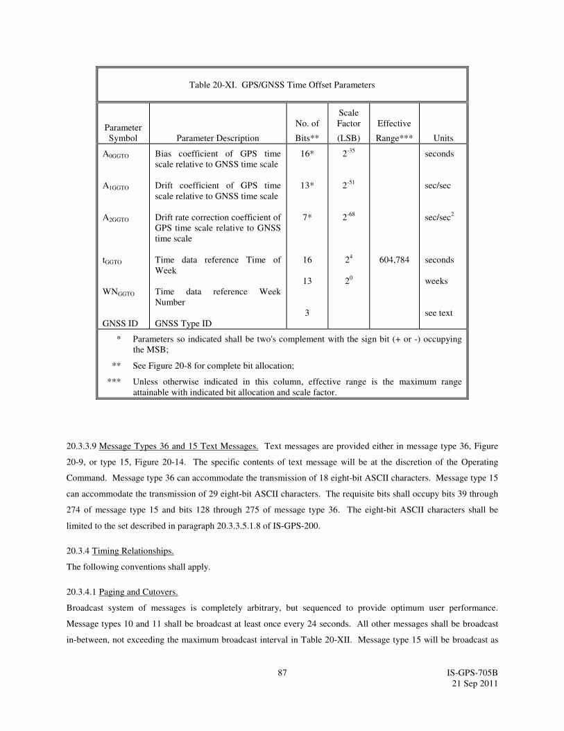
87 IS-GPS-705B
21 Sep 2011
Table 20-XI. GPS/GNSS Time Offset Parameters
Parameter
Symbol Parameter Description
No. of
Bits**
Scale
Factor
(LSB)
Effective
Range***
Units
A0GGTO
A1GGTO
A2GGTO
tGGTO
WNGGTO
GNSS ID
Bias coefficient of GPS time
scale relative to GNSS time scale
Drift coefficient of GPS time
scale relative to GNSS time scale
Drift rate correction coefficient of
GPS time scale relative to GNSS
time scale
Time data reference Time of
Week
Time data reference Week
Number
GNSS Type ID
16*
13*
7*
16
13
3
2-35
2-51
2-68
24
20
604,784
seconds
sec/sec
sec/sec2
seconds
weeks
see text
* Parameters so indicated shall be two's complement with the sign bit (+ or -) occupying
the MSB;
** See Figure 20-8 for complete bit allocation;
*** Unless otherwise indicated in this column, effective range is the maximum range
attainable with indicated bit allocation and scale factor.
20.3.3.9 Message Types 36 and 15 Text Messages. Text messages are provided either in message type 36, Figure
20-9, or type 15, Figure 20-14. The specific contents of text message will be at the discretion of the Operating
Command. Message type 36 can accommodate the transmission of 18 eight-bit ASCII characters. Message type 15
can accommodate the transmission of 29 eight-bit ASCII characters. The requisite bits shall occupy bits 39 through
274 of message type 15 and bits 128 through 275 of message type 36. The eight-bit ASCII characters shall be
limited to the set described in paragraph 20.3.3.5.1.8 of IS-GPS-200.
20.3.4 Timing Relationships.
The following conventions shall apply.
20.3.4.1 Paging and Cutovers.
Broadcast system of messages is completely arbitrary, but sequenced to provide optimum user performance.
Message types 10 and 11 shall be broadcast at least once every 24 seconds. All other messages shall be broadcast
in-between, not exceeding the maximum broadcast interval in Table 20-XII. Message type 15 will be broadcast as
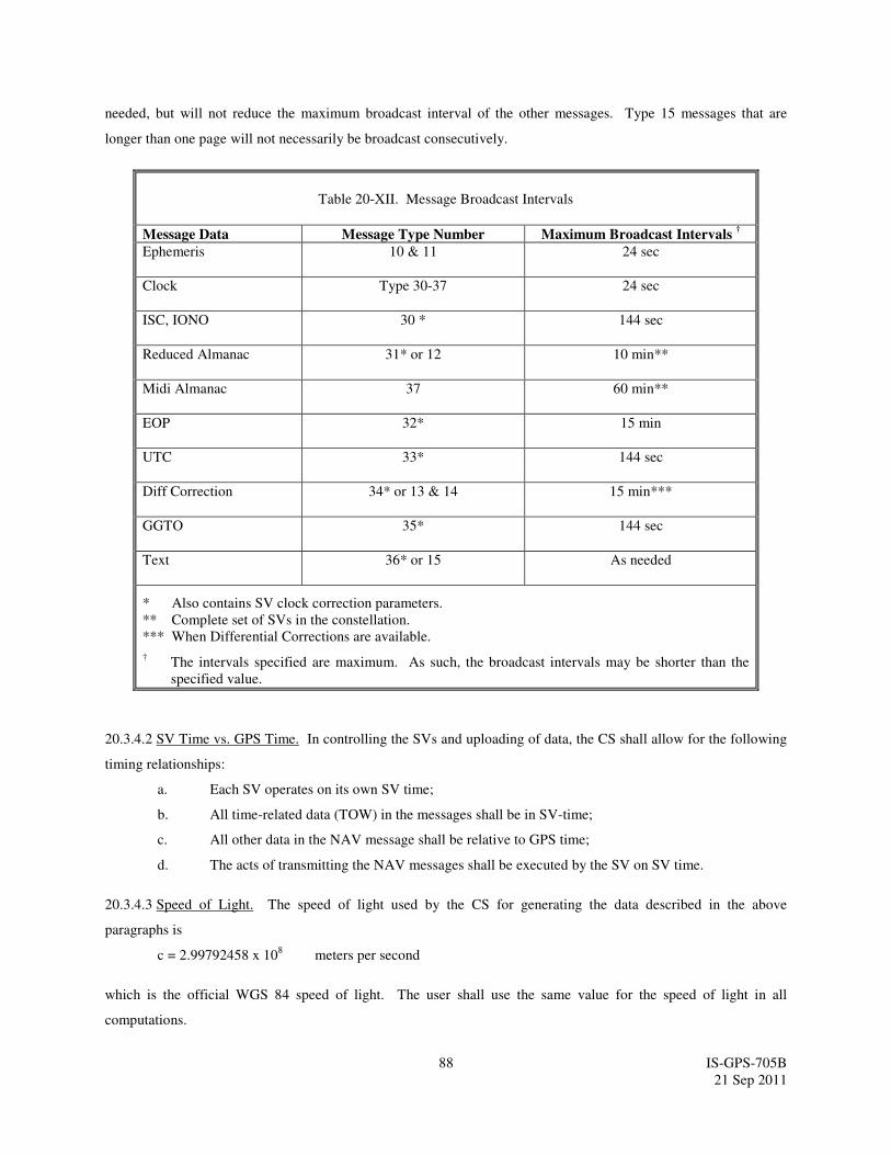
88 IS-GPS-705B
21 Sep 2011
needed, but will not reduce the maximum broadcast interval of the other messages. Type 15 messages that are
longer than one page will not necessarily be broadcast consecutively.
Table 20-XII. Message Broadcast Intervals
Message Data Message Type Number Maximum Broadcast Intervals †
Ephemeris 10 & 11 24 sec
Clock Type 30-37 24 sec
ISC, IONO 30 * 144 sec
Reduced Almanac 31* or 12 10 min**
Midi Almanac 37 60 min**
EOP 32* 15 min
UTC 33* 144 sec
Diff Correction 34* or 13 & 14 15 min***
GGTO 35* 144 sec
Text 36* or 15 As needed
* Also contains SV clock correction parameters.
** Complete set of SVs in the constellation.
*** When Differential Corrections are available.
† The intervals specified are maximum. As such, the broadcast intervals may be shorter than the
specified value.
20.3.4.2 SV Time vs. GPS Time. In controlling the SVs and uploading of data, the CS shall allow for the following
timing relationships:
a. Each SV operates on its own SV time;
b. All time-related data (TOW) in the messages shall be in SV-time;
c. All other data in the NAV message shall be relative to GPS time;
d. The acts of transmitting the NAV messages shall be executed by the SV on SV time.
20.3.4.3 Speed of Light. The speed of light used by the CS for generating the data described in the above
paragraphs is
c = 2.99792458 x 10⁸ meters per second
which is the official WGS 84 speed of light. The user shall use the same value for the speed of light in all
computations.

89 IS-GPS-705B
21 Sep 2011
20.3.4.4 Data Sets. The toe shall be equal to the toc of the same CNAV data set. The following rules govern the
transmission of toe and toc values in different data sets: (1) The transmitted toc will be different from any value
transmitted by the SV during the preceding seven days; (2) The transmitted toe will be different from any value
transmitted by the SV during the preceding six hours.
Cutovers to new data sets will occur only on hour boundaries except for the first data set of a new upload. The first
data set may be cut-in (reference paragraph 20.3.4.1) at any time during the hour and therefore may be transmitted
by the SV for less than one hour.
The start of the transmission interval for each data set corresponds to the beginning of the curve fit interval for the
data set. Each data set remains valid for the duration of its transmission interval, and nominally also remains valid
for the duration of its curve fit interval. A data set is rendered invalid before the end of its curve fit interval when it
is superseded by the SV cutting over to the first data set of a new upload.
Normal Operations. The message type 10, 11, and 30-37 data sets are transmitted by the SV for periods of two
hours. The corresponding curve fit interval is three hours.
20.3.4.5 Reference Times The LNAV reference time information in paragraph 20.3.4.5 in IS-GPS-200 also applies
to the CNAV reference times.
20.3.5 Data Frame Parity. The data signal contains parity coding according to the following conventions.
20.3.5.1 Parity Algorithm. Twenty-four bits of CRC parity will provide protection against burst as well as random
errors with a probability of undetected error ≤ 2-24
= 5.96 x 10⁻⁸
for all channel bit error probabilities ≤ 0.5. The
CRC word is calculated in the forward direction on a given message using a seed of 0. The sequence of 24 bits
(p1,p2,...,p24) is generated from the sequence of information bits (m1,m2,...,m276) in a given message. This is done
by means of a code that is generated by the polynomial.
( ) ∑=
=24
0i
i
i XgXg
where
otherwise0
24,23,18,17,14,11,10,7,6,5,4,3,1,0for1
=
== igi
This code is called CRC-24Q. The generator polynomial of this code is in the following form (using binary
polynomial algebra):
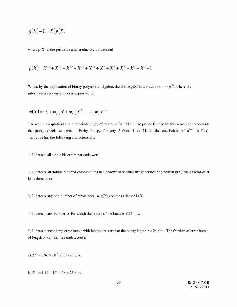
90 IS-GPS-705B
21 Sep 2011
( ) ( ) ( )XpXXg += 1
where p(X) is the primitive and irreducible polynomial
( ) 1357891112131723 ++++++++++= XXXXXXXXXXXp
When, by the application of binary polynomial algebra, the above g(X) is divided into m(x)x24
, where the
information sequence m(x) is expressed as
( ) 1
1
2
21
−
−− +⋅⋅⋅+++= k
kkk XmXmXmmXm
The result is a quotient and a remainder R(x) of degree < 24. The bit sequence formed by this remainder represents
the parity check sequence. Parity bit pi, for any i from 1 to 24, is the coefficient of x24-i
in R(x).
This code has the following characteristics:
1) It detects all single bit errors per code word.
2) It detects all double bit error combinations in a codeword because the generator polynomial g(X) has a factor of at
least three terms.
3) It detects any odd number of errors because g(X) contains a factor 1+X.
4) It detects any burst error for which the length of the burst is ≤ 24 bits.
5) It detects most large error bursts with length greater than the parity length r = 24 bits. The fraction of error bursts
of length b > 24 that are undetected is:
a) 2-24
= 5.96 × 10⁻⁸
, if b > 25 bits.
b) 2-23
= 1.19 × 10⁻⁷
, if b = 25 bits.