is an angular standard necessary for rotary encoders?
TRANSCRIPT
Research paper
−273 Synthesiology - English edition Vol.1 No.4 (2009)
the arm of a robot, smooth movement can be achieved by increasing the number of scale tick marks written on the 360º /cycle and thereby increasing the resolution. To control the position of the arm accurately, deviation between the angle information provided by the rotary encoder and the ideal angle position is evaluated, and accurate angle position control can be achieved by correcting the angle deviation. To accomplish this, it is necessary to measure the factor that cause the deviation of angle information obtained from the rotary encoder as shown in Fig. 1 and Fig. 2. However, although encoder manufacturers possessed technology to measure deviation in several tens of graduated scale, they did not have the technology to measure several thousands to ten thousands of scale, and therefore could not comprehensively and quantitatively evaluate various factors of angle deviation. As result, “accuracy” described in the product catalog of the encoder was not calibration curve that represents the angle deviation as shown in Fig. 3, but instead, it was safety tolerance where angle deviation is set as 0 and upper and lower lines are used to block off the large area of safety tolerance. Therefore, the “accuracy” as defined by the manufacturer was “black box” value where which angle deviation factors are included in what values were unknown.
1 Introduction
A rotary encoder is a device to measure angles, and is used in machine industry for machine tool and semiconductor manufacturing as well as for angle measurement and control of industrial robots. It enables complex and precise manufacturing by adding the freedom of polar coordinates for “angle” to Cartesian coordinates composed of “length.” Off ice pr inters are equipped with rotary encoder as mechanism for accurate paper feed to enable precise printing. Rotary encoder is used as measurement device for “angle” in wide-ranging field from advanced measurement to familiar office appliances. Users are now demanding higher resolution, smaller size, and higher function. Manufacturing companies have tried to meet user demand by creating products with various forms and functions such as absolute and incremental encoders, magnetic and optical encoders, and modular, hollow shaft, and shaft type encoders, and ones with or without bearing. Product with resolution of over 0.1˝ (1˝ = 1º /3600 = approximately 5 µrad) had been fabricated.
Recently, users star ted to demand reliability of angle information obtained from the rotary encoder. In controlling
- Development of a rotary encoder that enables visualization of angle deviation-
Tsukasa Watanabe
Planning Headquarters, AIST National Metrology Institute of Japan, AIST Tsukuba Centtral 2, Umezono 1-1-1, Tsukuba 305-8563, Japan E-mail:
A rotary encoder is an angular readout device that reads an optical pattern written on the circumference of a shaft similar to a 360 degrees protractor and outputs angle position information. Since the output of a rotary encoder deviates from the true angle position due to optical pattern errors or eccentricity of the shaft about the rotation axis, users have encountered difficulty in ensuring the reliability of the angle information derived from an encoder. In order to solve this problem, “SelfA: self-calibratable angle device” was developed. The SelfA can detect a variety of angle deviation sources by itself, and has the ability to output an angular calibration value. This SelfA can detect the angle deviation value from an optical encoder which has been a black box until now and enables “visualization” of these factors quantitatively.
Is an angular standard necessary for rotary encoders?
Keywords : Rotary encoder, angle standard, deviation evaluation, self-calibration
[Translation from Synthesiology, Vol.1, No.4, p.296-304 (2008)]
(53)−
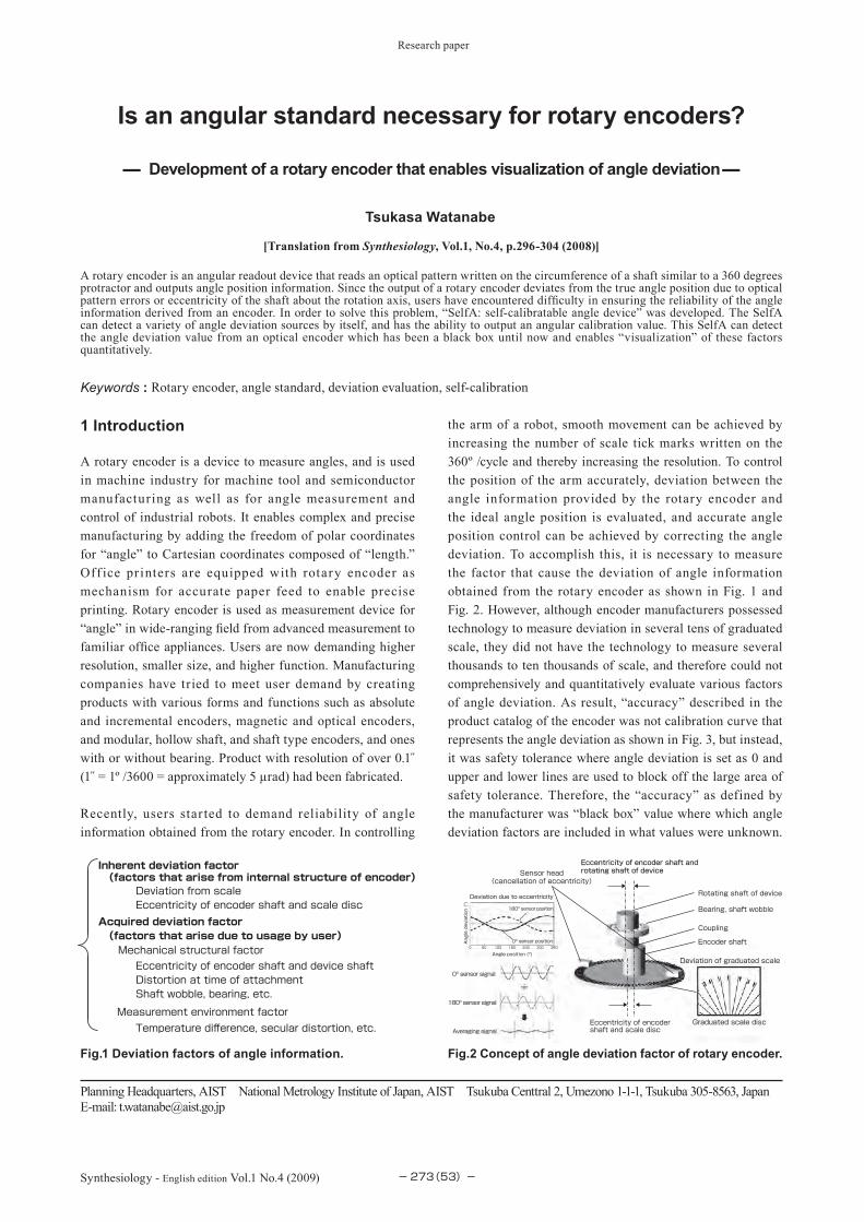
Fig.2 Concept of angle deviation factor of rotary encoder.Fig.1 Deviation factors of angle information.
Inherent deviation factor (factors that arise from internal structure of encoder)
Deviation from scaleEccentricity of encoder shaft and scale disc
Acquired deviation factor (factors that arise due to usage by user)Mechanical structural factorEccentricity of encoder shaft and device shaftDistortion at time of attachmentShaft wobble, bearing, etc.
Measurement environment factorTemperature difference, secular distortion, etc. Eccentricity of encoder
shaft and scale disc
Eccentricity of encoder shaft and rotating shaft of deviceSensor head
(cancellation of eccentricity)
Rotating shaft of device
Bearing, shaft wobble
Coupling
Encoder shaft
Deviation of graduated scale
Graduated scale disc
0º sensor signal
180º sensor signal
Averaging signal
180º sensor position
0º sensor position
Deviation due to eccentricity
Angle position (º)
Angle deviation (”)
0 60 120 180 240 300 360

Research paper : Is an angular standard necessary for rotary encoders? (T. Watanabe)
−274 Synthesiology - English edition Vol.1 No.4 (2009)
Users were forced to place confidence in this “accuracy” when they used the encoder, and had no clue for how to investigate angle deviation in the angle information, and did not know how to maintain reliability.
To maintain reliability of angle measurement demanded by users, other than the manufacturers’ effort in decreasing angle deviation through technological developments such as increasing precise and rigidity of the parts, breakthrough was necessary for new technological element that allowed measurement of angle deviation that could be done by users themselves and therefore improving reliability. “Visualization” of angle deviation as described in this paper is this breakthrough.
The National Institute of Advanced Industrial Science and Technology (AIST) has been conducting R&D of high-accuracy measurement device to establish the system of t raceability for providing measurement standard. Development of National Standard for Angle[1] was started in 1997. Currently, the originally developed angle calibration device can measure the angle deviation as calibration values of several hundred thousand graduated scales of rotary encoder in short time. With uncertainty of calibration value at 0.01 ,̋ it is a national standard with highest accuracy in the world. This paper describes our work on calibration technology for angle deviation by self-calibration method and the development of self-calibratable rotary encoder SelfA[2][3]. I shall also explain the methodology of the research.
2 Angle deviation and current situation
First, what are the angle deviations in the angle signals output by rotary encoder? The cause of angle deviation of rotary encoder can be roughly divided into inherent and acquired factors, as shown in Figs. 1 and 2.
Inherent factor of deviation is mainly caused by the structural defect of the rotary encoder itself, and is determined at the stage of manufacturing. This includes deviation factor of graduated scale and eccentricity factor of encoder shaft and graduated disc. The scale deviation factor is angle
deviation caused because the actual graduated scale does not correspond to the ideal graduated scale position with equal angle intervals as shown in Fig. 2 (bottom right). The eccentricity factor of encoder shaft and disc is angle deviation caused by the gap between the center of rotating shaft of rotary encoder and center of the scale disc.
Acquired factor of deviation is caused when the user attaches the rotary encoder to the device used or occurs during use. This may be caused by eccentricity of attachment of encoder shaft and rotating shaft of device, distortion of encoder during attachment, or distortion of encoder transferred from distortion of device due to temperature change during use. Moreover, shaft wobble dependent on the quality of bearing of device shaft may behave like motion eccentricity and cause angle deviation.
The eccentric errors between shaft-disc and shaft-shaft mentioned for inherent and acquired deviation factors are output as deviation represented as 1-period sine function as shown in Fig. 3.
To achieve high accuracy in rotary encoder, following technological methods were employed to keep the inherent and acquired deviation factors as small as possible.(1)Improvement of quality of tick marks of graduated scale
(spacing at equal angle interval, linearity of tick marks, etc.)
(2)Reduction of eccentricity by improving function of attachment jig and coupling
(3)Reduction of distortion by using robust and rigid parts to counter temperature change
(4)Cancellation technology for shaft eccentricity using 2 sensor heads
The items in (1)~ (3) a re methods for reducing the fundamental factors of angle deviation by increasing the preciseness of the parts of the rotary encoder. In contrast, cancellation technology for shaft eccentricity using two sensor heads is a method to cancel deviation caused by eccentricity in real time, as shown in Fig. 2 (left middle), by taking the average of signals measured by sensor heads that are accurately positioned at 180º opposite of each other on the graduated scale. As shown in Fig. 2 (left bottom), the sensor heads generate sine voltage signals for each interval between the graduated scales. If there is eccentricity, phase difference is produced in the sine voltage signals output by the sensor heads at 0º and 180º positions, and eccentricity can be cancelled by adding the two voltages. However, when the magnitude of eccentricity surpasses 1/4 of scale interval, or when the positioning accuracy of the sensor head surpasses 1/4 of scale interval, the voltage value may be reduced and the signal may not be output. For example, if the scale interval is 20 µm, shaft eccentricity and positioning accuracy of sensor head must be within 5 µm, so high preciseness of
(54)−
Fig. 3 Example of deviation factors in calibration curve.
Accuracy of
catalog listing
Deviation of graduated scale
Shaft eccentricity
Calibration curve
Angle deviation (”)
Angle position (º)
0 60 120 180 240 300 360-30
20
10
0
-10
-20
30
Research paper : Is an angular standard necessary for rotary encoders? (T. Watanabe)
−275 Synthesiology - English edition Vol.1 No.4 (2009)
the parts is necessary as in (1)~(3). Therefore, there is method of installing several sensor heads[4], but in practice, it is difficult to position four or more sensor heads due to problem of positioning accuracy.
3 Research scenario
Since the only information available to the user was “accuracy” according to “black box” catalog, the user must use the encoder installed in the device with doubt, since whether the angle deviation, which may be caused by shaft eccentricity of attachment and change in environment are within the tolerance range of catalog “accuracy,” is unknown. However, high accuracy measurement and control are possible by achieving several times higher accuracy compared to catalog “accuracy” by correcting the angle signal using the calibration value, if “visualization” of angle deviation can be achieved by calculating the calibration value (curve) of the rotary encoder as shown in Fig. 3.
The National Standard for Angle developed by AIST can measure angle deviation of graduated scale for several hundred thousand markings of rotary encoder. This enables quantitative evaluation of inherent and acquired deviation factors such as measurement environment, as shown in Fig. 1. However, almost all other acquired deviation factors vary and change according to individual difference of encoder, attachment, and environment used. Therefore, it is important for users to be able to “visualize” by measuring the calibration value when the encoder is installed in the device actually used. Therefore, we decided to achieve “visualization” of angle deviation by adding self-calibration function where the rotary encoder could measure the angle deviation and output the calibration value.
4 Self-calibratable rotary encoder “SelfA”
As shown in Table 1, several principles of self-calibration method[5]-[7] for measuring the angle deviation of rotary encoder have been devised. In the National Standard for Angle, the method for simultaneously recording the angle deviation of both encoders was employed by conducting self-calibration between the reference rotary encoder inside the National Standard and the user’s rotary encoder that was the subject of calibration, using EDA-method (equally divided average method) [8]. Therefore, we developed the National Standard type small calibration device[9] that enabled self-
calibration by EDA-method between the two encoders by installing separate encoder to the rotary encoder used by the user, as in the National Standard. However, it was difficult to obtain space for installing small National Standard around the rotary encoder that was already installed in the device used by the user, and we gave this up since we felt the limitation of downsizing.
Next, we investigated the principle of applying self-calibration using one rotary encoder. Multiple reproducing head method[10][11] and 3-point method[12] are methods in which several sensor heads are installed around the disc to measure the Fourier component by considering the angle deviation as consecutive 360º periodic curve as shown in Fig. 3. Using one of several sensor heads installed as standard, sensor heads are installed at 180º, 90º, 45º, 22.5º, etc. in case of multiple reproducing head method. In 3-point method, two places are selected from the arrangement of the multiple reproducing head method. This is a method where Fourier component can be obtained from the arrangement of other sensor heads against the standard sensor head, and calibration curve is obtained by inverse Fourier transformation. Therefore, accuracy of Fourier component that can be measured is greatly influenced by individual differences and accuracy of the sensor heads. Therefore, much labor is necessary for realization, and this method was not developed further.
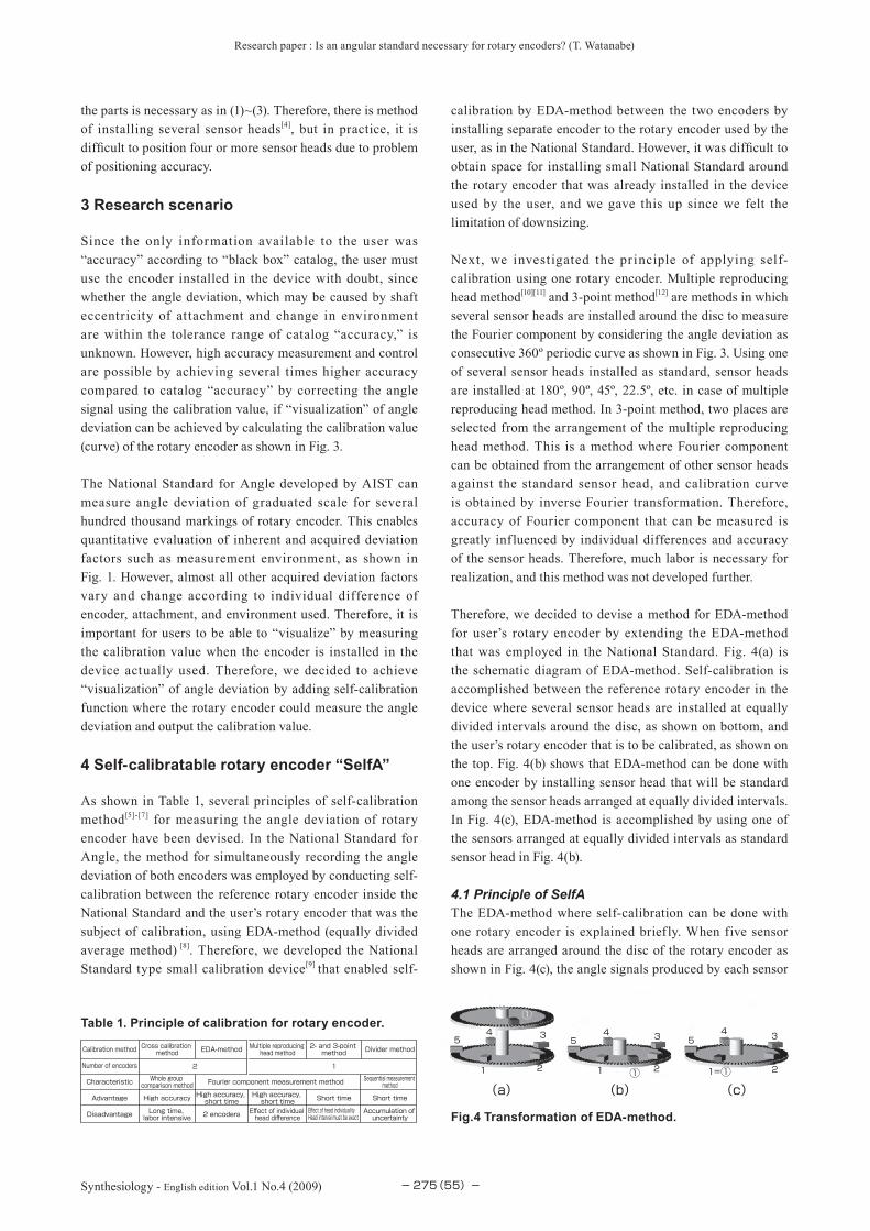
Therefore, we decided to devise a method for EDA-method for user’s rotary encoder by extending the EDA-method that was employed in the National Standard. Fig. 4(a) is the schematic diagram of EDA-method. Self-calibration is accomplished between the reference rotary encoder in the device where several sensor heads are installed at equally divided intervals around the disc, as shown on bottom, and the user’s rotary encoder that is to be calibrated, as shown on the top. Fig. 4(b) shows that EDA-method can be done with one encoder by installing sensor head that will be standard among the sensor heads arranged at equally divided intervals. In Fig. 4(c), EDA-method is accomplished by using one of the sensors arranged at equally divided intervals as standard sensor head in Fig. 4(b).
4.1 Principle of SelfAThe EDA-method where self-calibration can be done with one rotary encoder is explained briefly. When five sensor heads are arranged around the disc of the rotary encoder as shown in Fig. 4(c), the angle signals produced by each sensor
(55)−
Fig.4 Transformation of EDA-method.Accumulation of uncertainty
Short time
Sequential measurement method
Divider method
Head interval must be exactEffect of head individuality
Short time
2- and 3-point method
Effect of individual head difference
High accuracy, short time
Fourier component measurement method
Multiple reproducing head method
2 encoders
High accuracy, short time
EDA-method
Long time, labor intensive
High accuracy
Whole group comparison method
Cross calibration method
Disadvantage
Advantage
Characteristic
Number of encoders
Calibration method
12
Table 1. Principle of calibration for rotary encoder.①
54 3
21
54 3
21
54 3
21=① ①
(a) (b) (c)

Research paper : Is an angular standard necessary for rotary encoders? (T. Watanabe)
−276 Synthesiology - English edition Vol.1 No.4 (2009)
head include angle deviations A1, A2, A3, A4, and A5. However, since each sensor head measures the same disc, A2, A3, A4,and A5 are phase shifted by 72º intervals against A1. Since angle deviations cannot be directly separated from the angle signals, by calculating the difference between the angle signal of the first sensor head that has been set as standard, difference can be expressed only by angle deviation, as in equation (1). The example of measurement values of for 360º cycle is shown in Fig. 5.
δ1=A1−A1 δ2=A1−A2 δ3=A1−A3 δ4=A1−A4 δ5=A1−A5 (1)
Next, when the average value µ of the five is calculated, following equation is obtained. Fig. 6 shows the result when the average value µ of the five in Fig. 5 is calculated.
µ=−Σδj=A1−−(A1+A2+A3+A4+A5)(2)
The first term of right side is angle deviation of rotary encoder or the calibration value, but the average µ of the analyzed value cannot be called calibration value as is, due to the presence of second term. To check the relationship between first and second terms, the second term is calculated by creating A2, A3, A4, and A5 that are shifted by 72º phases, assuming that
the calibration value of A1 is obtained. Then the Fourier component has the relationship as shown in Fig. 7. It can be seen that the second term on right side is equal to the 5th order component of Fourier component of A1. That is, when five sensor heads are installed, average µ is the calibration value of A1 that does not include the 5th order component according to second term. When the effect of 5th order component on the calibration value is great, calibration value of higher accuracy can be obtained by arranging different number of sensor heads, for example seven. Since the calibration values obtained is measurement of specific Fourier component, this principle is categorized as method for Fourier component measurement as shown in Table 1.
The characteristic of this principle is that there is very little influence on angle deviation even if there is some shift in sensor head arrangement, because in the aforementioned multiple reproducing head and 3-point methods, statistic accuracy can be increased by calculating each sensor head that are arranged at equal angle intervals as standard, rather than relying on the relationship of one standard sensor head against all other sensor heads. Also, analysis can be done by four arithmetic operations without using Fourier transformation or inverse Fourier transformation.
4.2 Application of SelfAAs shown in Fig. 8, we developed a rotary table equipped with self-calibratable rotary encoder where 10 sensor heads are arranged on the bottom. Figure 9 shows the calibration
(56)−
5
j=1
Fig. 5 Data output from SelfA.
Fig. 6 Analysis result of SelfA.
Angle position ( ° )
Angle deviation ( ″ )
0 60 120 180 240 300 360
20
10
0
-10
-20
Angle position ( ° )
Angle deviation ( ″ )
0 60 120 180 240 300 360
20
10
0
-10
-20
Fig. 7 Analysis result and relationship with Fourier component.
0 5 10 15 20 25 30 35 40 45 50
Second termCalibration value A
Fourier component strength
Fourier order
Sensor head
Fig. 8 Rotating table equipped with self-calibratable rotary encoder “ SelfA”.
5511
Research paper : Is an angular standard necessary for rotary encoders? (T. Watanabe)
−277 Synthesiology - English edition Vol.1 No.4 (2009)
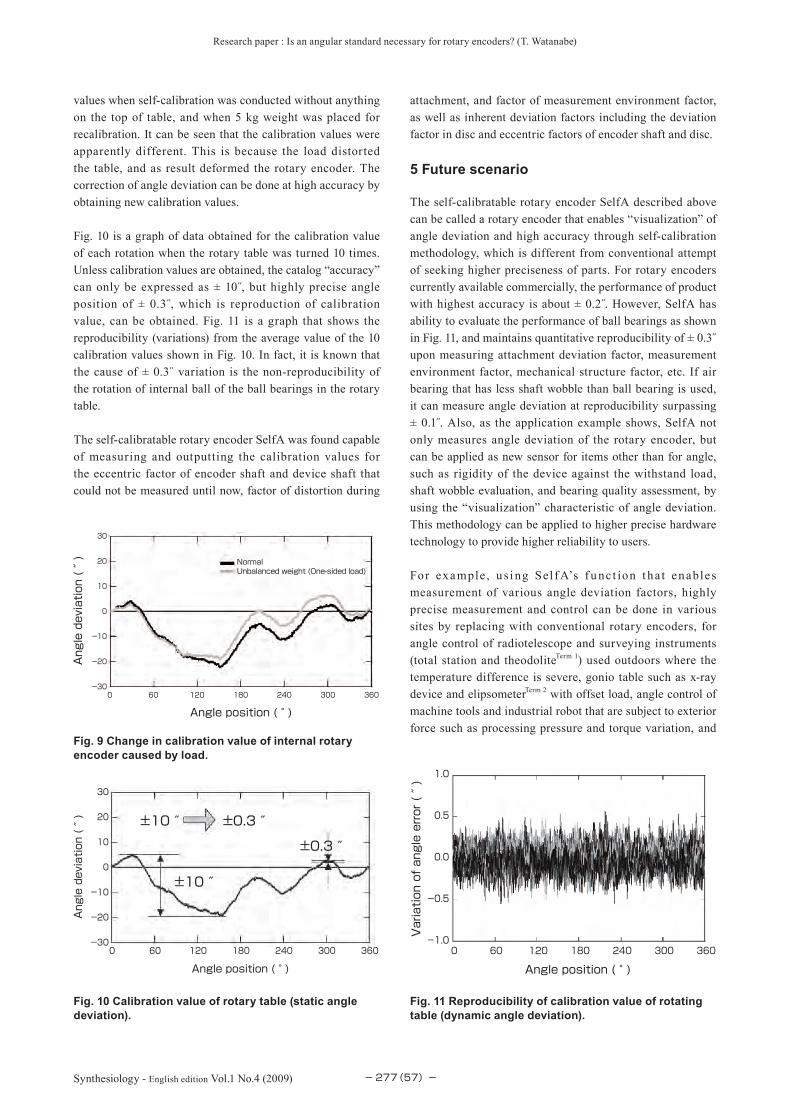
values when self-calibration was conducted without anything on the top of table, and when 5 kg weight was placed for recalibration. It can be seen that the calibration values were apparently different. This is because the load distorted the table, and as result deformed the rotary encoder. The correction of angle deviation can be done at high accuracy by obtaining new calibration values.
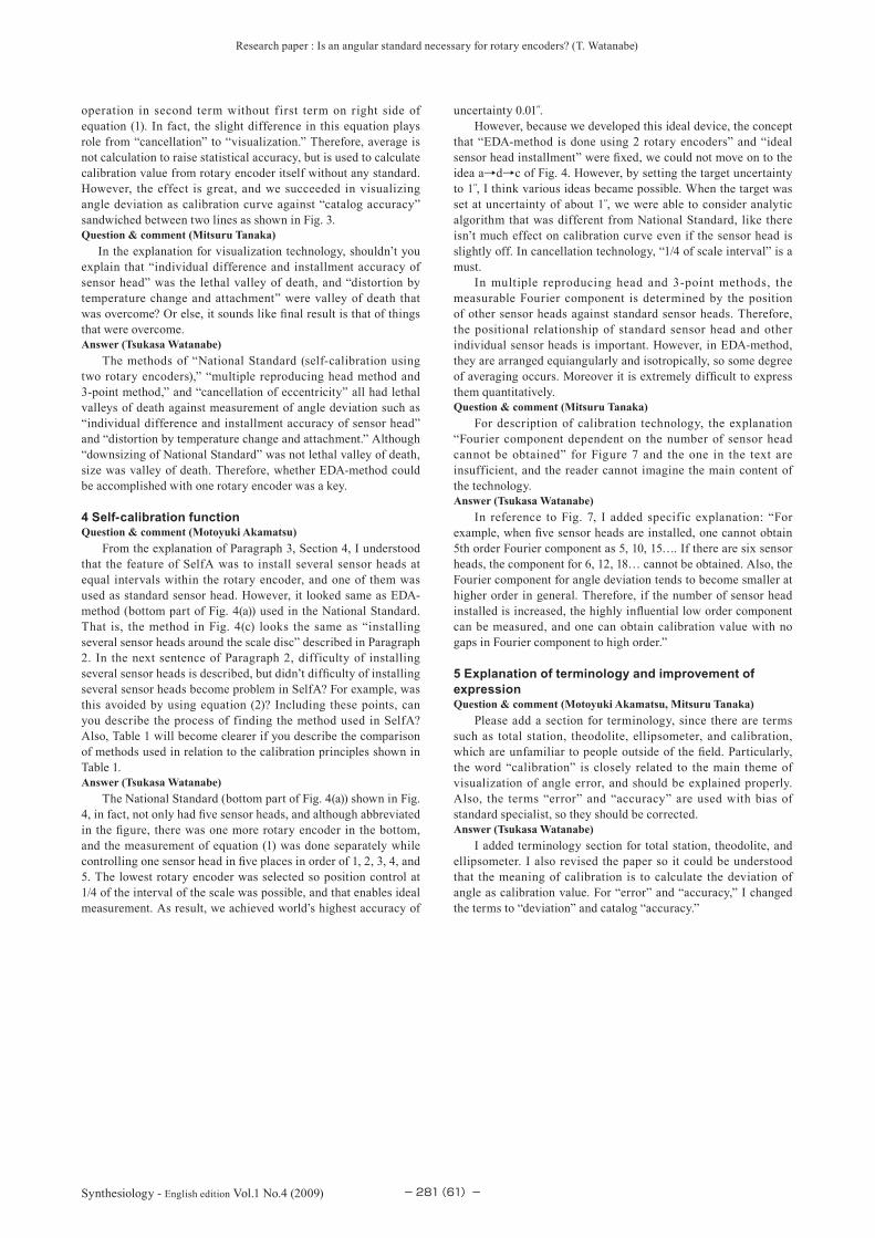
Fig. 10 is a graph of data obtained for the calibration value of each rotation when the rotary table was turned 10 times. Unless calibration values are obtained, the catalog “accuracy” can only be expressed as ± 10˝, but highly precise angle position of ± 0.3˝, which is reproduction of calibration value, can be obtained. Fig. 11 is a graph that shows the reproducibility (variations) from the average value of the 10 calibration values shown in Fig. 10. In fact, it is known that the cause of ± 0.3˝ variation is the non-reproducibility of the rotation of internal ball of the ball bearings in the rotary table.
The self-calibratable rotary encoder SelfA was found capable of measuring and outputting the calibration values for the eccentric factor of encoder shaft and device shaft that could not be measured until now, factor of distortion during
attachment, and factor of measurement environment factor, as well as inherent deviation factors including the deviation factor in disc and eccentric factors of encoder shaft and disc.
5 Future scenario
The self-calibratable rotary encoder SelfA described above can be called a rotary encoder that enables “visualization” of angle deviation and high accuracy through self-calibration methodology, which is different from conventional attempt of seeking higher preciseness of parts. For rotary encoders currently available commercially, the performance of product with highest accuracy is about ± 0.2 .̋ However, SelfA has ability to evaluate the performance of ball bearings as shown in Fig. 11, and maintains quantitative reproducibility of ± 0.3˝ upon measuring attachment deviation factor, measurement environment factor, mechanical structure factor, etc. If air bearing that has less shaft wobble than ball bearing is used, it can measure angle deviation at reproducibility surpassing ± 0.1 .̋ Also, as the application example shows, SelfA not only measures angle deviation of the rotary encoder, but can be applied as new sensor for items other than for angle, such as rigidity of the device against the withstand load, shaft wobble evaluation, and bearing quality assessment, by using the “visualization” characteristic of angle deviation. This methodology can be applied to higher precise hardware technology to provide higher reliability to users.
For example , u si ng Sel f A’s f u nc t ion t ha t enables measurement of various angle deviation factors, highly precise measurement and control can be done in various sites by replacing with conventional rotary encoders, for angle control of radiotelescope and surveying instruments (total station and theodoliteTerm 1) used outdoors where the temperature difference is severe, gonio table such as x-ray device and elipsometerTerm 2 with offset load, angle control of machine tools and industrial robot that are subject to exterior force such as processing pressure and torque variation, and
(57)−
Fig. 9 Change in calibration value of internal rotary encoder caused by load.
0 60 120 180 240 300 360-30
20
10
0
-10
-20
30
NormalUnbalanced weight (One-sided load)
Angle position ( ° )
Angle deviation ( ″ )
Fig. 10 Calibration value of rotary table (static angle deviation).
0 60 120 180 240 300 360-30
20
10
0
-10
-20
30
±10 ″
±10 ″ ±0.3 ″
±0.3 ″
Angle position ( ° )
Angle deviation ( ″ )
Fig. 11 Reproducibility of calibration value of rotating table (dynamic angle deviation).
0 60 120 180 240 300 360-1.0
1.0
0.5
0.0
-0.5
Angle position ( ° )
Variation of angle error ( ″ )

Research paper : Is an angular standard necessary for rotary encoders? (T. Watanabe)
−278 Synthesiology - English edition Vol.1 No.4 (2009) (58)−
accuracy evaluation of bearing used.
To realize this, development of SelfA in various sizes is necessary so the users can replace the inbuilt rotary encoder with SelfA described here without altering their current devices.
6 Know-how for practical application
Here, I present the necessary technological know-hows in utilizing self-calibratable rotary encoder SelfA.
6.1 Number of sensor headsAs indicated in Fig. 7, the Fourier component dependent on the number of sensor head cannot be obtained from the angle deviation obtained from the principle of SelfA. For example, when five sensor heads are installed, one cannot obtain 5th order Fourier component as 5, 10, 15…. If there are six sensor heads, the component for 6, 12, 18… cannot be obtained. Also, the Fourier component for angle deviation tends to become smaller at higher order in general. Therefore, if the number of sensor head installed is increased, the highly inf luential low order component can be measured, and one can obtain calibration value with no gaps in Fourier component to high order. Fig. 12 shows the relationship of number of sensor heads and achievable accuracy. For example if the achievable accuracy is 0.1 ,̋ 10~15 sensors are necessary, but five is sufficient for 1 .̋ Therefore, it is not necessary to use so many sensor heads depending on the accuracy desired by the user, and optimal number of sensor heads can be selected.
6.2 Arrangement preciseness of sensor headIn conventional rotary encoder, two sensor heads had to be installed with strict limitation of 1/4 or less of scale interval to cancel the angle deviation by eccentricity. Moreover, shaft eccentricity and scale deviation variation were limited to 1/4 or less of scale interval. SelfA requires installation of not just two, but several sensor heads on the disc at equal
angle intervals, and one may question the actual realization of Self A. The answer is “yes.” SelfA does not require real time analysis, because each sensor head records the measured angle signal of the scale position by computer, and the difference of equations (1) and (2) are calculated after the measurements are completed, and the measurements can be done even if there is angle deviation that surpass the scale interval by eccentricity. Also, the sensor head does not output angle signal for each and every scale tick marks, but outputs angle signal as average value of several tens or several hundreds tick marks as shown in Fig. 13. Therefore, the change of angle deviation between proximal angle signals is small, so there is no particularly great effect on calibration value if they are installed few ticks away.
7 Summary
The development of rotary encoders by companies was conducted under methodology of reducing angle deviation by employing precision parts or to erase the deviation with cancellation technology. However, development in this research employs visualization method by actively presenting all angle deviation. The companies that aimed for product with small angle deviation as possible and the stance of this research that aimed to evaluate angle deviation by development of National Standard for Angles enabled the development of the new self-calibratable rotary encoder SelfA.
The National Standard for Angle calibrates rotary encoder by EDA-method, which is one of self-calibration methodologies, rather than high accuracy angle standard. This means that any user or company can possess “angle standard” equivalent to the National Standard. Moreover, self-calibratable rotary encoder SelfA itself is capable of measuring angle deviation without calibrating device. This means that user or company may not need to own “angle standard.” However, what becomes unnecessary is higher level “angle standard,” and “angle standard” will become more familiar with the diffusion of self-calibratable rotary encoder SelfA.
As “things that cannot be measured cannot be made,”
Fig. 12 Relationship between number of sensor head of SelfA and achieved accuracy.
1005 10 15 20 25 30
0.01
0.1
1
10
Angle deviation detecting ability of SelfA ( ″ )
Number of sensor head
Fig. 13 Scale measurement size of rotary encoder.
Scale tick marks
Sensing range of sensor head

Research paper : Is an angular standard necessary for rotary encoders? (T. Watanabe)
−279 Synthesiology - English edition Vol.1 No.4 (2009)
establishment of high accuracy measurement technology is mandatory in manufacturing. “Visualization” of high accuracy status is thought to increase the reliability of accuracy evaluation that was done blindly until now, and is thought to contribute further for advanced manufacturing.
Terminology
Term 1. Total station,Thedolite: Theodolite is a surveying instrument to measure angle. It is optical device to measure the rotational angle in horizontal and vertical directions in triangulation. Total station is a theodolite with mechanism to measure distance to the target.
Term 2. Ellipsometer: Ellipsometery is measurement done by irradiating light onto sample and measuring the elliptic polarization of light ref lected by sample. The device analyzes the optical constants such as thickness of film and refraction and coefficient of absorption. Rotary encoder is used to measure angle of reflection.
(59)−
[1]
[2]
[3]
[4]
[5]
[6]
[7]
[8]
[9]
[10]
[11]
[12]
T. Watanabe, T. Masuda, M. Kajitani, H. Fujimoto, and T. Nakayama: Automatic high accuracy calibration system for rotary encoder, Journal of the Japan Accuracy Engineering Society, 67 (7), 1091-1095 (2001) (in Japanese).T. Watanabe, H. Fujimoto and T. Masuda: Self-calibratable rotary encoder, J. Physics: Conference Series, 13, 240-245 (2005).Patent 3826207: Angle detector with self-calibration capability (in Japanese).Published Patent Hei6 (1994)-313719: Rotary encoder (in Japanese).X. D. Lu and D. L. Trumper: Self-calibration of on-axis rotary encoders, Annals of the CIRP, 56 (1), 499-504 (2007).K. Štépánek: Messung der Genauigkeit von Getrieben und Winkeln mit magnetischen Ma stäben, acta IMEKO, Proc. Int. Meas. Conf., 1st, 258 (1958).E. W. Palmer: High-Accuracy Angle Measurement, NPL, Teddington, U.K. (1984).T. Masuda and M. Kajitani: High accuracy calibration system for angular encoders, J. Robotics and Mechatronics, 5 (5), 448-452 (1993).Published Patent 2000-258186: Self-calibrating angle detector and calibration method for detection accuracy (in Japanese).Published Patent 2003-262518: Self-calibrating angle detector (in Japanese).T. Masuda and M. Kajitani: Automatic calibration system for angular encoders, Journal of the Japan Accuracy Engineering Society, 52 (10), 1732-1738 (1986) (in Japanese).Published Patent Hei6(1994)-317431: Calibration method for encoder (in Japanese).
Received original manuscript August 8, 2008Revisions received October 28, 2008
Accepted October 28, 2008
References
Author
Tsukasa WatanabeCompleted doctorate at Department of Physics, Tohoku University in 1993. Doctor (Physics). After working as visiting researcher at National Institute of Standards and Technology (NIST) of USA, joined the National Research Laboratory of Metrology, Agency of Industrial Science and Technology (current AIST). Worked on development of National Standard of Angle. Currently working on world standard of angles with the diffusion of new angle standard using self-calibratable rotary encoder. Winner of Ichimura Prize and Tsukuba Encouragement Award.
Discussion with Reviewers
1 Aim of research and titleQuestion & comment (Motoyuki Akamatsu)
This research, in which the angle calibration technology for angle standard is developed into technology to maintain reliability of rotary encoder, is an excellent example of utilizing basic research in the society. The objective of this research is improvement of reliability, where the accuracy of encoder that is attached as a product can be calibrated frequently, and the accuracy can be maintained. However, I think the impact of introduction of this research result into the society, as “improvement of reliability” is difficult to understand to the general reader. How about adding explanation and emphasizing the social impact? Also, please reconsider the title and subtitle to emphasize the social impact.Answer (Tsukasa Watanabe)
Although there are 100 years of history for length standard, and the world has developed national standards using same principle at same pace, there are only 20 years of history for angle standard. AIST started development of National Standard 10 years ago, but the principles for national standard around the world are diverse and not unified. Moreover, other countries increased preciseness of the parts to improve the accuracy of their national standards, and as result, the device became expensive and complex. This is the barrier that prevents common principle to this day. However, National Standard of AIST employs EDA-method as mentioned in this paper. Based on this principle, anyone can own device equivalent to National Standard.
This research star ted from making this principle more compact and creating a device that can be used inexpensively and simply by anyone. It is true that there was ambivalence and conflict in creating a standard while creating device that does not require standard.
Since the history of angle standard is still young, there are many black boxes such as what factors cause deviation in angle measurement devices and how such factors can be estimated. For “improvement of reliability,” we can obtain hint for opening the lid of the black box and thereby enabling quantitative evaluation unlike the “accuracy” described in the catalog, and both manufacturer and user can engage in discussion under same perspective on factors that cause angle deviation. I think that is truly standard for angle.
I drastically changed the title and subtitle as follows.
Development of self-calibratable rotary encoder- Realization of improvement of angle accuracy and reliability of visualization of deviation factor ↓

Research paper : Is an angular standard necessary for rotary encoders? (T. Watanabe)
−280 Synthesiology - English edition Vol.1 No.4 (2009) (60)−
Is an angular standard necessary for rotary encoders?- Development of a rotary encoder that enables visualization of angle deviationQuestion & comment (Mitsuru Tanaka)
In paragraph 2 of chapter 1, it is unclear why recent users are having trouble due to lack of reliability in accuracy. It is important to indicate what should have been the function desired by the encoder users, if it was not resolution. Also, I think it is good that you focused on situation “after installation” which is very important for the user. However, guarantee of reliability of angle value after installation to the customer’s device is the job of users, so shouldn’t it be, “Users are having trouble because they cannot guarantee the reliability of angle information obtained from the encoder after installation”?Answer (Tsukasa Watanabe)
In the middle of chapter 1, I added explanation of reasons why the resolution and angle deviation became black box using the example of robot arm. As mentioned in chapter 2, I divided the inherent factors of angle deviation determined at the manufacturing stage of the rotary encoder, and the acquired factors of angle deviation determined when the user uses the rotary encoder. By doing so, I was able to explain the difference in catalog “accuracy” and the actual rotary encoder that are currently commercially available. The items with which the users are finding trouble can be specified, and I was able to provide explanation as you have indicated.
Therefore, I changed the expression to the following sentence: “Users were forced to place confidence in this “accuracy” when they used the encoder, and had no clue for how to investigate angle deviation in the angle information, and did not know how to maintain reliability.”
2 “Visualization” as breakthroughQuestion & comment (Motoyuki Akamatsu)
In paragraph 3, chapter 1, you write about the necessity of introducing new technology to improve reliability and also mention that “visualization” is necessary as breakthrough. Can you explain the scenario for selection of technology, such as whether “visualization” was mandatory for improvement of reliability, or whether “visualization” was selected over other options?Answer (Tsukasa Watanabe)
There are several factors that cause angle deviation in angle signal output from the rotary encoder. I divided them as static and dynamic error factors, but I decided this categorization was not appropriate for the paper. The angle deviations generated by manufacturer and user are ultimately synthesized and expressed as inseparable angle deviation. Therefore, I changed the category into inherent and acquired factors of angle deviation. However, the most serious problem was that both manufacturer and user did not have ways of quantitatively evaluating angle deviation, and this lead to black boxing of angle deviation and decreased the reliability.
The companies used two hands, “increasing preciseness of parts” and “cancellation of deviation (eccentricity)” to keep the black box as small as possible. These two technologies will undoubtedly remain important technologies. However, the paper suggested a third hand, “self-calibration function” or “visualization.”
I presented the reason for introducing “visualization” by expanding on chapter 2.
I wished there were better names for inherent and acquired factors of angle deviation.Question & comment (Mitsuru Tanaka)
Dividing static and dynamic factors of angle error as in this paragraph should be part of elemental discussion in terms
of methodological description. However, more you explain this division, I find it more difficult to understand the relationship between “conventional” and “visualization.” Isn’t there any way of making it clear? I think it will help to sort out the scheme of static = manufacturer/other-calibration = conventional and dynamic = user/self-calibration = visualization.Answer (Tsukasa Watanabe)
I changed from categorization of “static and dynamic factors of angle error” to “inherent and acquired factors of angle deviation.” I also explained (1)~(4) which are efforts by manufacturers to reduce the inherent factors of angle deviation.Question & comment (Mitsuru Tanaka)
For research scenario, it can be said that this description is the essence of methodology. However, if it is so important for users themselves to “see,” shouldn’t you emphasize that? You say “visualization,” but it is unclear about who is doing the seeing. Also, while it took lots of time, manpower, and cost to “see,” now it became simple (that is, by self-calibration). Isn’t this the development of methodology?Answer (Tsukasa Watanabe)
The problem is that the manufacturer did not possess device to evaluate inherent angle deviation, and for users, all angle deviation were in black box so they had no idea how to take measures against the actual angle deviation or how to deal with catalog “accuracy.” It was necessary to introduce technology where the users, as well as manufacturers, can measure angle deviation themselves to enable “visualization” of angle deviation. To do this, rather than evaluating the rotary encoder installed in the device, the rotary encoder itself could output angle deviation to conduct “visualization” of angle deviation easily and in short time, without requiring other device.Question & comment (Mitsuru Tanaka)
The reader wil l be confused unless you explain the relationships among National Standard, encoder “made” by manufacturers, encoder “used” by users, and “encoder” that is calibrated in the research scenario. Also it is unclear why downsizing is necessary.Answer (Tsukasa Watanabe)
I added the words “user,” “National Standard,” and “reference” in front of “rotary encoder” to clarify which rotary encoder was being discussed. Since the technology for “visualizing” angle deviation is complex, manufacturer and user become reluctant to use them when the device becomes large. Therefore, if the objectives are practical use and diffusion, it is necessary to allow “visualization” of angle deviation while it keeping the device almost same size as currently used rotary encoder. I specified the text as follows: “However, it was difficult to obtain space for installing small National Standard around the rotary encoder that was already installed in the device used by the user, and we gave this up since we felt the limitation of downsizing.”
3 “Visualization” technologyQuestion & comment (Motoyuki Akamatsu)
It is argued that the point of this technological development is “visualization,” but I think it is slightly different from the general meaning of “visualization,” that is to understand the situation by visualizing the data. From the description of the paper, I understood that this development is about increasing accuracy by using the average values as calibration data, but if this is so, I don’t think it is necessity to visualize. If you are using “visualization” as having different meaning from analysis based on visualizing, please add an explanation.Answer (Tsukasa Watanabe)
Rotary encoder equipped with two or four sensor heads are marketed. However, they were used for cancellation of certain angle deviation such as shaft eccentricity. This is average
Research paper : Is an angular standard necessary for rotary encoders? (T. Watanabe)
−281 Synthesiology - English edition Vol.1 No.4 (2009) (61)−
operation in second term without first term on right side of equation (1). In fact, the slight difference in this equation plays role from “cancellation” to “visualization.” Therefore, average is not calculation to raise statistical accuracy, but is used to calculate calibration value from rotary encoder itself without any standard. However, the effect is great, and we succeeded in visualizing angle deviation as calibration curve against “catalog accuracy” sandwiched between two lines as shown in Fig. 3.Question & comment (Mitsuru Tanaka)
In the explanation for visualization technology, shouldn’t you explain that “individual difference and installment accuracy of sensor head” was the lethal valley of death, and “distortion by temperature change and attachment” were valley of death that was overcome? Or else, it sounds like final result is that of things that were overcome.Answer (Tsukasa Watanabe)
The methods of “National Standard (self-calibration using two rotary encoders),” “multiple reproducing head method and 3-point method,” and “cancellation of eccentricity” all had lethal valleys of death against measurement of angle deviation such as “individual difference and installment accuracy of sensor head” and “distortion by temperature change and attachment.” Although “downsizing of National Standard” was not lethal valley of death, size was valley of death. Therefore, whether EDA-method could be accomplished with one rotary encoder was a key.
4 Self-calibration functionQuestion & comment (Motoyuki Akamatsu)
From the explanation of Paragraph 3, Section 4, I understood that the feature of SelfA was to install several sensor heads at equal intervals within the rotary encoder, and one of them was used as standard sensor head. However, it looked same as EDA-method (bottom part of Fig. 4(a)) used in the National Standard. That is, the method in Fig. 4(c) looks the same as “installing several sensor heads around the scale disc” described in Paragraph 2. In the next sentence of Paragraph 2, difficulty of installing several sensor heads is described, but didn’t difficulty of installing several sensor heads become problem in SelfA? For example, was this avoided by using equation (2)? Including these points, can you describe the process of finding the method used in SelfA? Also, Table 1 will become clearer if you describe the comparison of methods used in relation to the calibration principles shown in Table 1.Answer (Tsukasa Watanabe)
The National Standard (bottom part of Fig. 4(a)) shown in Fig. 4, in fact, not only had five sensor heads, and although abbreviated in the figure, there was one more rotary encoder in the bottom, and the measurement of equation (1) was done separately while controlling one sensor head in five places in order of 1, 2, 3, 4, and 5. The lowest rotary encoder was selected so position control at 1/4 of the interval of the scale was possible, and that enables ideal measurement. As result, we achieved world’s highest accuracy of
uncertainty 0.01 .̋However, because we developed this ideal device, the concept
that “EDA-method is done using 2 rotary encoders” and “ideal sensor head installment” were fixed, we could not move on to the idea a→d→c of Fig. 4. However, by setting the target uncertainty to 1 ,̋ I think various ideas became possible. When the target was set at uncertainty of about 1 ,̋ we were able to consider analytic algorithm that was different from National Standard, like there isn’t much effect on calibration curve even if the sensor head is slightly off. In cancellation technology, “1/4 of scale interval” is a must.
In multiple reproducing head and 3-point methods, the measurable Fourier component is determined by the position of other sensor heads against standard sensor heads. Therefore, the positional relationship of standard sensor head and other individual sensor heads is important. However, in EDA-method, they are arranged equiangularly and isotropically, so some degree of averaging occurs. Moreover it is extremely difficult to express them quantitatively. Question & comment (Mitsuru Tanaka)
For description of calibration technology, the explanation “Fourier component dependent on the number of sensor head cannot be obtained” for Figure 7 and the one in the text are insufficient, and the reader cannot imagine the main content of the technology.Answer (Tsukasa Watanabe)
In reference to Fig. 7, I added specific explanation: “For example, when five sensor heads are installed, one cannot obtain 5th order Fourier component as 5, 10, 15…. If there are six sensor heads, the component for 6, 12, 18… cannot be obtained. Also, the Fourier component for angle deviation tends to become smaller at higher order in general. Therefore, if the number of sensor head installed is increased, the highly influential low order component can be measured, and one can obtain calibration value with no gaps in Fourier component to high order.”
5 Explanation of terminology and improvement of expressionQuestion & comment (Motoyuki Akamatsu, Mitsuru Tanaka)
Please add a section for terminology, since there are terms such as total station, theodolite, ellipsometer, and calibration, which are unfamiliar to people outside of the field. Particularly, the word “calibration” is closely related to the main theme of visualization of angle error, and should be explained properly. Also, the terms “error” and “accuracy” are used with bias of standard specialist, so they should be corrected.Answer (Tsukasa Watanabe)
I added terminology section for total station, theodolite, and ellipsometer. I also revised the paper so it could be understood that the meaning of calibration is to calculate the deviation of angle as calibration value. For “error” and “accuracy,” I changed the terms to “deviation” and catalog “accuracy.”