is a item - welding.com.au€¦ · essential to supply correct model identification and machine...
TRANSCRIPT

WELDMATIC 400
MODEL NO. C P 4
"""""
C A T . 7524/4
.6/80
FROP4 S E R I A L N O . 40043
"THE INFORMATION CONTAINED I N T H E F O L D E R I S S E T O U T T O E N A B L E YOU T O P R O P E R L Y M A I N T A I N YOUR NEW EQUIPMENT AND ENSURE THAT YOU O B T A I N MAXIMUM O P E R A T I N G E F F I C I E N C Y .
P L E A S E E N S U R E T H A T T H I S F O L D E R I S K E P T I N A S A F E P L A C E F O R READY REFERENCE WHEN R E Q U I R E D .
WHEN REQUESTING SPARE PARTS, QUOTE THE MODEL NO. AND SERIAL NO. OF THE MACHINE AND THE PART NO. OF THE ITEM R E Q U I R E D . F A I L U R E TO S U P P L Y T H I S 1 N F O F . M A T I O N WILL R E S U L T I N U N N E C E S S A R Y D E L A Y S I N S U P P L Y I N G T H E C O R R E C T P A R T S .
W E L D I N G I N D U S T R I E S O F A U S T R A L I A P T Y . L T D .
M e l b o u r n e 429 4766 Sydney 60.7 2 6 5 5 N e w c a s t l e 61 1668 A d e l a i d e 352 3022 P e r t h 361 7088 B r i s b a n e 44 1391 Launces ton 31 7004 D a r w i n 81 6427 & 84 3076

OPERATING AND MAINTENANCE INSTRUCTIONS
WELDMATIC 400 (CP4)
INTRODUCTION
GENERAL
T h i s manual has been prepared e s p e c i a l l y f o r u s e i n familiar- i z i n g p e r s o n n e l w i t h t h e d e s i g n , i n s t a l l a t i o n , o p e r a t i o n , main tenance , and t roubleshoot ing o f t h i s equipment . A l l i n f o r m a t i o n presented h e r e i n s h o u l d be g i v e n c a r e f u l c o n s i d - e r a t i o n t o a s s u r e optimum performance of t h i s e q u i p m e n t .
RECEIVING/HANDLING.
P r i o r t o i n s t a l l i n g t h i s equ ipmen t , c l ean a l l p a c k i n g m a t e r i a l from a r o u n d t h e u n i t a n d c a r e f u l l y i n s p e c t fo r any damage t h a t may have occu r red du r ing sh ipmen t . Any claims f o r loses or damage t h a t may h a v e o c c u r r e d i n t r a n s i t m u s t be f i l e d by t h e p u r c h a s e r w i t h W e l d i n g I n d u s t r i e s of A u s t r a J i a P t y . L t d . or a u t h o r i s e d a g e n t i m m e d i a t e l y (refer t o EQUIPMENT WARRANTY card e n c l o s e d w i t h O p e r a t i n g I n s t r u c t i o n M a n u a l ) .
When r e q u e s t i n g i n f o r m a t i o n c o n c e r n i n g t h i s e q u i p m e n t , it i s essent ia l t o supply correct Model i d e n t i f i c a t i o n a n d m a c h i n e s e r i a l number.
SAFETY.
Before the equ ipmen t i s p u t i n t o o p e r a t i o n , t h e SAFETY PRACTICES s e c t i o n a t t h e back o f t h i s m a n u a l MUST BE READ COMPLETELY. T h i s w i l l help a v o i d p o s s i b l e i n j u r y d u e t o misuse o r improper
.. - w e l d i n g a p p l i c a t i o n s .
CONTENTS
G e n e r a l D e s c r i p t i o n
S e t t i n g u p for Opera t ion
PAGE NO.
1
2 - 3
Welding Operation I n s t r u c t i o n s 4
M a i n t e n a n c e I n s t r u c t i o n s 5 - 6
Welding Data - Table 'IC" 7 - Par ts L i s t CP4-02 I s s u e 4 8
- Assembly Drawing CP4-02 I s s u e 2. 9
C i r c u i t Diagrams - CP4 - C 9 10
Mobile K i t Assembly - AM116 S a f e t y Practices
Guarantee Card

STANDARD UNIT
The construction of the standard package plant has been designed for ins ta l la t ion and operating i n a wide variety of applications, such as high production factories and general fabrication shops,
"WELDMATIC" Plants consists of three basic u n i t s : - 1. Constant Potential Rectifier Power Source. 2 . Semi-Automatic Wire Feeder. 3 . Welding Gun and Cable Assembly.
Separate operating and maintenance instructions are provided for the wire feeder and gun cables.
1. POWER SOURCE - FEATURES
The standard C.P. r e c t i f i e r power source i s housed i n a drip- proof enclosure. Lifting lugs are provided for crane trans- portation. For u n i t s w i t h wheel mounting four solid rubber tyred wheels are provided: the two front wheels are steerable permitting easy movement i n r e s t r i c t ed f l o o r space. A push bar i s provided on the front of the machine and a gas cylinder ca r r i e r w i t h a support bracket and chain a t the rear . A 110 v o l t plug socket i s located on the rear panel for connection of gas preheater when welding w i t h C 0 2 gas shield. Located on the front panel are a coarse voltage selection switch, fine voltage selection switch, power ON/OFF switch, control fuses, wire feeder plug socket and r e c t i f i e r power outlet sockets.
2. CONSTRUCTION_
The power source i s a Constant Potential Sil icon Diode Rectifier D.C. Welder, w i t h a three phase transformer and a three phase rect i f ier br idge. Connected i n the output circuit i s an induc- tance u n i t providing the "inductance" or degree of slope neces- sary for various welding currents. Cooling of the s i l icon diodes, transformer windings and inductance u n i t i s by a single phase axial f an . The power source i s protected against fan fa i lure and overheating by thermostats mounted on diode heat s i n k s .
3 . WELDING PROCESS I
Gas metal arc welding w i t h i n the capacity of the power source can be carried out w i t h the fo l lowing equipment:- a) Semi-automatic wire feeder model W14. b) Semi-automatic wire feeder w i t h spot timer W14-20. c ) "Hobart" spool gun welding u n i t model SP9 w i t h CV2 controller. d ) "Mini-mig" push and p u l l gun and control.
4. WELDING CAPACITY
Power Source Capacity i s as follows:- 400 Amps, 42 vo l t s , 100% du ty cycle.
-2-
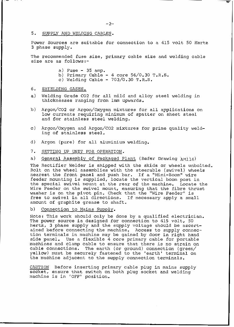
5. SUPPLY AND WELDING CABLES.
Power Sources a re s u i t a b l e for c o n n e c t i o n to a 415 vo l t 50 Hertz 3 phase supp ly .
The recommended f u s e s i z e , p r i m a r y cable s i z e a n d w e l d i n g cable s i z e are as f o l l o w s : -
a ) Fuse - 35 amp. b ) Pr imary Cable - 4 c o r e 56/0.30 T.R.S. c ) Welding Cable - 703/0.30 T.R.S.
SHIELDING GASES.
Welding Grade C 0 2 for a l l mild a n d a l l o y s t ee l w e l d i n g i n t h i c k n e s s e s r a n g i n g from lmm upwards.
Argon/COZ or Argon/Oxygen m i x t u r e s f o r all a p p l i c a t i o n s o n l o w c u r r e n t s r e q u i r i n g minimum of spat ter o n s h e e t s teel and fo r s t a i n l e s s s teel weld ing .
Argon/Oxygen and Argon/C02 m i x t u r e s for p r i m e q u a l i t y weld- i n g of s t a i n l e s s s tee l .
Argon ( p u r e ) f o r a l l alum.inium welding.
SETTING UP UNIT FOR OPERATION.
Genera l Assembly o f Packaqed P l an t (Refer Drawing Apqjjs) The R e c t i f i e r Welder i s s h i p p e d w i t h t h e s k i d s or whee l s unbo l t ed . B o l t on t h e w h e e l assemblies w i t h t h e steerable ( s w i v e l ) w h e e l s nearest t h e f r o n t pane l and push bar. If a "Mini-Boom" wire f eede r moun t ing i s s u p p l i e d , locate t h e v e r t i c a l boom p o s t i n t h e s p e c i a l s w i v e l mount a t t h e rear of t h e machine. Locate t h e Wire Feeder on t h e s w i v e l m o u n t , e n s u r i n g t h a t t h e f ibre t h r u s t washer i s on t h e p i v o t p i n . Check t h a t t h e "Wire Feeder" i s free t o swivel i n a11 d i r e c t i o n s . If n e c e s s a r y a p p l y a small a m o u n t o f g r a p h i t e g r e a s e t o s h a f t .
b ) Connect ion t o Mains Supply. Note: T h i s work shou ld on ly be done by a q u a l i f i e d e l e c t r i c i a n . The power s o u r c e i s d e s i g n e d fo r c o n n e c t i o n t o 415 v o l t , 50 h e r t z , 3 phase supply and t h e s u p p l y v o l t a g e s h o u l d be ascert- a i n e d before connec t ing t he mach ine . Access t o supply connec- t i o n t e r m i n a l s i n m a c h i n e m.ay be ga ined by door i n r i g h t hand side pane l . U s e a f l ex ib l e 4 core p r imary cable f o r p o r t a b l e machines and clamp cable t o e n s u r e t h a t t h e r e i s n o s t r a i n o n cable c o n n e c t i o n s . T h e e a r t h ( o r g round) connec t ion (g reen / ye l low) mus t be s e c u r e l y f a s t e n e d t o t h e ' e a r t h ' t e r m i n a l o n t h e m.achine a d j a c e n t t o t h e s u p p l y c o n n e c t i o n terminals .
CAUTION Before i n s e r t i n g p r i m a r y cable p l u g i n m.ains supply socket, e n s u r e t h a t swi tch on both p l u g socket and weld ing machine i s i n 'OFF' p o s i t i o n .

- 3-
c ) Connection of Cables/Hoses, e tc . With u n i t switched 'OFF' connect control cable ( 6 p i n plug) from power source t o wire feeder. Connect gas hose from wire feeder t o gas regulator/flowmeter, ensuring a l l connections are tightened firmly. If C 0 2 Gas Shield i s being used, p lug heater into 110 volt socket a t r e a r . o f u n i t . Next i n se r t gun cable into socket of wire feeder output guide and r e t a in i n place w i t h s e t screw provided. Set screw should not be t igh t - ened so as t o prevent gun cable from swivelling. Connect "Gas Hose" and "Gun Switch'' leads to respective sockets.
d ) WELDING CABLES.
A l l G.M.A. welding i s done w i t h electrode wire connected t o "positive" pole commonly known as D.C. reverse polarity (D.C.R,P.) therefore, connect the short jumper lead from I I + I I
socket on machine to terminal lug on gun cable. The work lead ("negative") should be plugged !into the ' I - ' ' socket on the machine. The plugs of the welding cables must be fu l ly inserted i n the sockets, to prevent accidental disconnection. T o avoid e r ro r , welding should not be attempted u n t i l a l l connections have been secured. The wire feeder may be ins t - a l led remote from the power source, i n which case, extension lead sets comprising power cable, gas hose and control cable (four core) are required i n accordance w i t h the desired length. Standard length available from stock i s 9 metres.
e ) WIRE FEEDER AND GUN CABLE.
F i t a spool of wire t o the wire feeder (see notes i n "Wire Feeder Instruction Manual"). Tighten the "brake" screw u n t i l a sl ight braking effect i s f e l t when turning the wire spool by hand t o prevent "over-run" when wire feed stops. The wire dr ive ro l l s and inlet wire guide should be selected i n accord- ance w i t h the diameter and type of wire being used. Refer t o current wire feeder manual for correct se lect ion of wire feed r o l l s and i n p u t quides.
0.8m = 0.030" l .6mm = 1/16" 0 . 9 m = 0.035" 2.4m = 3/32" 1.2m = 0.045" 3.2mm = 1/8"
The gun cable and gun are normally delivered w i t h the contact t i p and l iner spr ing for wire s ize nominated, but check tha t both are correct size for wire being used.

-4-
WELDING OPERATION INSTRUCTIONS
8. SINGLE FUNCTION CHECK
Uni t i s now ready for operat ion, but pr ior to commencing weld- ing, the following "functions check" i s recommended, switch on power source and check a i r flow. See tha t a11 welding lead plugs are inserted i n the correct polarity sockets - electrode "positive" , work "negative" . Check a l l welding connections and plugs for t ightness particuarly "work" clamp.
Next ensure that a l l control cables and gas hoses are securely connected and tha t Gas Heater ( f o r C 0 2 only) i s plugged i n t o socket a t r e a r of power source. Switch on wire feeder, indic- a tor l ight should now show "Power On". Open Gas cyl inder ful ly and check contents gauge for adequate gas supply.
Press "Gas Purge" switch and s e t gas flow i n accordance w i t h welding requirements, a t t he same time check t h a t gas .Elow i s adequate from gun nozzle. Set "wire speed" control t o desired wire speed, Press "wire inch" switch and check wire feed for correct pressure on drive rolls . Pressure should be suf f ic ien t t o prevent any llslip'l when feeding through gun and cable,
Next, close gun switch momentarily for wire feed, gas flow and welding power check. Set the voltage selector switches i n accordance w i t h required voltage (see welding table), u n i t i s now ready for welding.
9. SETTING O F WELDING CURRENT, VOLTAGE AND INDUCTANCE.
The welding current i s determined automatically by "Wire Speed". The electrode wire i s fed at the pre-selected speed by the drive r o l l s through the gun cable t o the a rc a t a constant speed, unchanged except when rese t by the "Wire Speed" control. The higher the wire speed, the higher the welding current, as w i l l be indicated by the ammeter. The output voltage of the power source, indicated by the voltmeter when the gun switch i s closed, i s divided i n t o a number of steps by Coarse Selector and Fine Selector switches. The CP4 has Coarse Voltage and Fine Voltage switches each w i t h six steps giving 36 voltage se t t ing for the machine.
The inductance terminal sockets are numbered "1 - 4". Depending on the type of welding conditions various inductance values are required, The typical weld set t ing char t indicates the recommended sockets for various welding mnditions. A s a general rule, low welding currents require inductance No.1 or 2.
For aluminium and tubular flux cored wire, Inductance Socket No.1 is used exclusively.
The following sequence of weld se t t i ng i s recommended:- a > Consult typical weld se t t ing char t .

- 5 -
b ) Select welding current most sui ted to the appl icat ion by following the settings of wire speed and voltage shown on t h e se t t ing char t , T o "tune" each weld sett ing, adjust wire speed only.
c ) I f vo l t age i s t oo low for the application, wire "stubbing" w i l l occur , par t icu lar ly a t s ta r t of weld and weld contour w i l l be very convex. If the voltage i s too high, metal transfer w i l l be e r r a t i c w i t h excess spatter.
d ) With welding current and voltage matched the resu l t w i l l be an optimum tuned welding condition w i t h a sm.ooth spatter-free arc.
10. . SAFETY DEVICES
I n the event of the power source becom.ing overheated the ther- mostats on the diode heat s i n k s w i l l operate preventing further welding. The thermostats w i l l automatically reset and w i t h the cooling fan operating t h i s w i l l take approximately 10 minutes. A check should be made to ascertain the reason for the over- heating such as fan not operating or air flow restricted. Fuses provided f o r a l l c i r c u i t s a r e as follows and are indicated on the front panel:-
Fuse E l - 3 amps (Delayed action) Fuse E2 - 3 amps ( ' I l' '. . > Fuse E3 - 5 amps ( I' 1 Fuse E4 - 5 amps ( 'I It )
11. YINTENANCE
a ) Power Source Apart from the fan the rectifier has no rotary components. To achieve complete dissipation of heat from. the active components, t h e r e c t i f i e r should be thoroughly blown off w i t h dry compressed a i r a f t e r 6 months' operation. Cleaning should be carried out a t shorter intervals i f d u s t accumulation i s considerable.
Prior to cleaning, remove the u n i t cover by detachment of lugs and the f ixing screws. Thus a l l t h e components of t he power source w i l l be accessible.
b) The wire feed motor/gearbox i s pre-packed w i t h grease and needs no other lubrication. Change the grease after approximately 14,000 service hours. (see Wire Feeder Instruction Manual).
The d r ive ro l le rs and the inner wire guides should be kept clean. If necessary, blow off the inside of the wire feeder w i t h com- pressed air .

-6-
cl Gun and Cable
Remove any spatter w h i c h m i g h t a d h e r e t o t h e n o z z l e b o r e so t h a t t h e s h i e l d i n g gas o u t f l o w i s n o t impeded. T h e c o n d i t i o n of t h e contact t u b e s s h o u l d be r e g u l a r l y c h e c k e d . Damaged and/ or b u r n t t u b e s are an impediment t o t r o u b l e - f r e e w e l d i n g operation and should be rep laced immedia t e ly .
T r o u b l e - f r e e o p e r a t i o n d e p e n d s t o a large e x t e n t on t h e good c o n d i t i o n a n d c l e a n l i n e s s of t h e i n n e r wire l i n e r (See I n s t r u c - t i o n s o n Gun Cables).
12 . WELDING OPERATION_ Never observe t h e arc w i t h u n p r o t e c t e d e y e s . I t i s of import- a n c e t h a t t h e welder wear protective c l o t h i n g p r o v i d i n g s u f f i c - i e n t s a f e t y ,
13. STOPPAGES AND THEIR ELIMINATION
The machine should be checked on ly by a f u l l y sk i l l ed e l e c t r i c i a n .
If t h e u n i t stops working, f i r s t de te rmine whe the r s toppages are i n i t i a t e d b y t h e ma ins ( for i n s t a n c e , b u r n t f u s e ) or by t h e supp ly cable (loose connec t ion , cable break) or b y t h e u n i t proper.
If t h e t h r e e t e r m i n a l s L1, L2 and L3 o n t h e p r i m a r y t e r m i n a l board are correctly connec ted .to t h e m a i n s ( v o l t m e t e r r e a d i n g ) t h e cause of t h e s t o p p a g e m u s t be s o u g h t i n t h e u n i t i t s e l f .
The w i r i n g diagram o n t h e n e x t pages w i l l f a c i l i t a t e t h e l o c a t i o n of t h e defect.
b
- 7 -
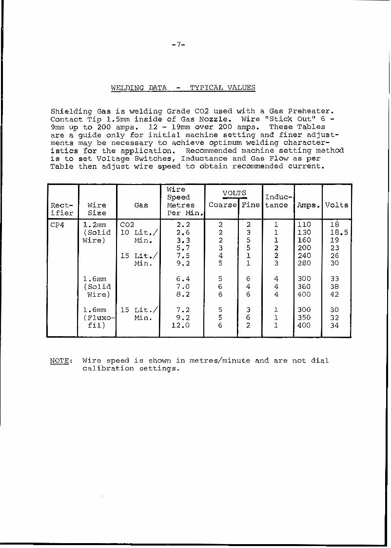
WELDING DATA - TYPICAL VALUES
Shielding Gas i s welding Grade C 0 2 used w i t h a Gas Preheater. Contact Tip 1 , S m inside of Gas Nozzle, Wire "Stick Out" 6 - 9mm up to 200 amps. L2 - 1 9 m . over 200 amps. These Tables are a guide only for init ial machine se t t i ng and finer adjust- ments may be necessary t o achieve optimum. welding character- ist ics for the application. Recommended machine se t t i ng method i s t o s e t Voltage §witches, Inductance and Gas Flow as per Table then adjust wire speed to obtain recommended current.
Rect- i f i e r CP4
Wire Gas Size
1.2msn. C 0 2 (Solid 10 L i t . / Wire) Min.
1 5 L i t . / Min.
1.6mm ( S o l i d wire)
1.6mrn I15 L i t . /
Wire Speed Metres Per Min
2 . 2 2.6 3.3 5.7 7.5 9.2
6.4 7.0 8 . 2
7.2 9 . 2
12.0
v 01 Coarse
2 2 2 3 4 5
5 6 6
5 5 6
S
Fine I
2 3 5 5 l. 1
6 4 6
3 6 2
Induc- tance
1 1 1 2 2 3
4 4 4
1 1 1
Amps . Volts
110 18 130 18.5 160 19 200 23 240 26 280 30
300 3 3 360 38 400 42
300 30 350 32 400 34
Wire speed i s shown i n metres/minute and are not dial cal ibrat ion set t ings.

- ITEM
ALL 2
2 . 1
2 . 2
2 . 3
3
3 . 1
3 . 2
3 . 3
4
4 . 1
4 . 2
5 8
9
1 8
2 1
22
24
2 5
2 6
2 6 . 1
27
2 8
29
30
32
33
34
3 7
3 7 . 1
3 7 . 2
3 8
39
-8-
DRAWING NO. CP4-02 - SPARE PARTS LIST ISSUE 6
PART NO.
CP4-32
CP15-13/2
CP15-13/3
CP3-9/8
CP4-8
CP4-19/1
CP4-19/2
CP4-19/3
CP4-2
CP4-7/1
CP4-7/2
CP25-0/7
CP3-0/4
MC35-0/6
CP15-0/7
CP4-16
CP5-0/19
AM16
CP15-0/14
TC262
TC262N
CP3-0/47
CP5-0/16
w1-22
CP5-0/17
CP5-0/13
CP5-0/14
CP5-0/15
W1-23
K 1 0
K 1 1
CP32-5
CP22-2/13
DESCRIPTION
RECTIFIER ASSEMBLY
DIODE
DIODE ( R )
THERMOSTAT
TRANSFORMER ASSEMBLY
R . H . PRIMARY/SEC . COIL
CENTRE PRIMARY/SEC. COIL
L.H. PRIMARY/SEC. COIL
INDUCTANCE ASSEMBLY
LEFT HAND INDUCTANCE COIL
RIGHT HAND INDUCTANCE COIL
CONTROL TRANSFORMER
FAN BLADE
FAN MOTOR
GAS HEATER PLUG SOCKET
RECTIFIER PROTECTION ASSEMBLY
WELDING CONTACTOR
OUTPUT TERMINALS
CONTROL PLUG
GAS NIPPLE
GAS NIPPLE NUT
VOLTMETER 0-60V
AMMETER 0-600A
INDICATOR LIGHT
AMMETER SHUNT 0-600A
POWER ON/OFF SWITCH
COARSE VOLTAGE SWITCH
FINE VOLTAGE SWITCH
FUSE HOLDER
3AG. 3A. DELAY FUSE
3 A G . 5 A . DELAY FUSE
RESISTOR
STAND OFF INSULATOR

-@ "0 -0 "@
" - 1 B=&-- 8"
I
-0 4- 3 l
-0 @-
-8
;1 P A

4 1

0

SAFE PRACTICES I N USING WELDING EQUIPMENT
Produced by Welding I n d u s t r i e s o f A u s t r a l i a P t y . L t d . i n t h e i n t e r e s t s o f improving operator safety. These notes should be cons idered on ly as a b a s i c gu ide t o Sa fe Working Habi ts . A f u l l l i s t o f S t anda rds pe r t a in ing t o i ndus t ry i s a v a i l a b l e from the S tandards Assoc ia t ion of Aus t ra l ia , a l so var ious S ta te Electricity Authorit ies, Departments of Labour and Industry or Mines Depart- ment and other Local Heal th or Safety Inspect ion Authori t ies may have addi t iona l requi rements .
1. A nea t unc lu t t e red work a rea makes fo r s a fe work ing hab i t s .
2 . Burn Prevent ion
The welding arc is in t ense and v i s i b l y b r i g h t . I t s r ad ia t ion can damage eyes , pene t r a t e l i gh twe igh t c lo th ing , r e f l ec t f rom l i gh t - co lou red su r f aces , and burn t h e s k i n and eyes. Skin burns resemble acute sunburn, those from gas-shielded arcs a r e mre severe and painful .
Wear p r o t e c t i v e c l o t h i n g - l ea ther (or asbes tos) gaunt le t g loves , ha t , and sa fe ty - toe boo t s . Bu t ton sh i r t collar and pocket f laps , and wear c u f f l e s s t rouse r s t o avo id en t ry o f spa rks and s l a g .
NEVER LOOK AT AN ARC WITHOUT PROTECTION.
Wear he lmet wi th sa fe ty goggles o r g lasses wi th s ide sh ie lds undernea th , a p p r o p r i a t e f i l t e r l e n s e s o r p l a t e s ( p r o t e c t e d by c l e a r c o v e r g l a s s ) . T h i s is a MUST for weld ing or cu t t i ng , ( and ch ipp ing) t o p ro t ec t t he eyes from radian t energy and f ly ing metal. Replace cover glass when b r o k e n , p i t t e d , o r s p a t t e r e d .
Avoid o i l y o r g r e a s y c l o t h i n g . A spark may i g n i t e them. Hot metal such as e l e c t r o d e stubs and workpieces should never he handled without gloves.
Ear plugs should be worn when w e l d i n g i n o v e r h e a d p o s i t i o n s o r i n a confined space. A hard hat should be worn when o t h e r s work overhead.
Flammable ha i r p repa ra t ions shou ld no t be used by persons intending to weld o r c u t .
3 . Toxic Fume Prevention
Adequate vent i la t ion is e s s e n t i a l . S e v e r e d i s c o m f o r t , i l l n e s s o r d e a t h c a n r e s u l t from fumes, vapors, heat, or oxygen enrichment o r d e p l e t i o n t h a t w e l d i n g ( o r c u t t i n g ) may produce. Prevent them with adequate ventilation. NEVER vent i la te with oxygen.
Lead, cadium, zinc, mercury, and beryll ium bearing and similar materials when welded ( o r c u t ) may produce harmful concentrations of toxic fumes. Adequate l o c a l e x h a u s t v e n t i l a t i o n must be used , o r each pe r son i n t he a r ea as well as t h e o p e r a t o r must wear an a i r - supp l i ed r e sp i r a to r . Fo r be ry l l i um, bo th must be used. Metals coa ted w i th o r con ta in ing materials t h a t emit fumes should not be hea ted un less coa t ing i s removed from t h e work s u r f a c e , t h e a r e a i s w e l l v e n t i l a t e d , o r t h e o p e r a t o r wears an a i r - s u p p l i e d r e s p i r a t o r .
Work i n a confined space only while it i s b e i n g v e n t i l a t e d a n d , i f n e c e s s a r y , whi le wear ing a i r - suppl ied resp i ra tor .
Vapors from chlor ina ted so lvents can be decomposed by t h e h e a t o f t h e a r c ( o r f l ame) t o form PHOSGENE, a h igh ly t ox ic gas , and lung and eye i r r i t a t i n g products . The u l t r a - v i o l e t ( r a d i a n t ) e n e r g y o f t h e a r c c a n a l s o decompose t r i ch lo re thy lene and pe rch lo re thy lene vapor s t o form phosgene. D o n o t WELD o r c u t where solvent vapors can be drawn in to the weld ing or cu t t ing a tmosphere o r where the rad ian t energy can pene t ra te to a tmospheres conta in ing even minute amounts of t r i ch lo re thy lene o r pe rcho lo re thy lene .

4 . F i r e and Explosion Prevention
Causes of f i r e and explosion are:- Combustibles reached by the a r c , f l ame , f l y - i ng spa rks , ho t s l ag , o r hea t ed ma te r i a l ; m i suse of compressed gases and cylin- d e r s ; a n d s h o r t c i r c u i t s .
Be aware t h a t f l y i n g s p a r k s o r f a l l i n g s l a g c a n p a s s t h r o u g h c r a c k s , a l o n g p i p e s , through windows o r d o o r s , and through wall o r f loo r open ings , ou t o f s igh t of the goggled operator . Sparks and s l ag can f l y 10 metres .
To p r e v e n t f i r e s and explosions:- Keep equipment cl.ean and operable, free of o i l , g r e a s e , and ( i n e l e c t r i c a l p a r t s ) o f m e t a l l i c p a r t i c l e s t h a t can cause short c i r c u i t s .
I f combus t ib l e s a r e i n a r e a , do NOT weld o r c u t . Move the work i f p r a c t i c a b l e , to an a rea f ree o f combust ib les . Avoid p a i n t s p r a y rooms, d ip t anks , s to rage a r e a s , v e n t i l a t o r s . I f t he work can not be m v e d , move combustibles a t l e a s t 10 metres away out of reach of sparks and heat ; or p r o t e c t a g a i n s t i g n i t i o n w i t h su i t ab le and snug- f i t t i ng f i r e - r e s i s t an t cove r s o r sh i e lds .
Walls touching combustibles on opposite sides should not be welded on ( o r c u t ) . W a l l s , c e i l i n g s , and f loo r nea r work should be pr'otected by hea t - r e s i s t an t cove r s o r s h i e l d s . Fire watcher must be s tanding by wi th su i tab le f i re ex t inguish ing equipment during and for some t i m e a f t e r w e l d i n g o r c u t t i n g i f :
(1) combust ib les ( inc luding bu i ld ing cons t ruc t ion) a re wi th in LO metres. (11) combust ib les a re fur ther than 10 metres but can be ignited by sparks . (111) openings (concea led o r v i s ib le ) i n f l o o r s o r walls w i t h i n l 0 me t re s
(1V) combus t ib l e s ad j acen t t o wa l l s , c e i l i ngs , roo f s , o r me ta l pa r t i t i ons may expose combustibles to sparks.
can be igni ted by rad ian t o r conducted hea t .
Af t e r work is done, check t h a t a r e a is free of sparks , g lowing embers , and flames.
An empty container that . held combust ibles , o r can produce flamable vapors when hea ted , must never be welded on o r c u t , u n l e s s c o n t a i n e r h a s f i r s t b e e n c l e a n e d as descr ibed i n AS.1674-1974, t he S . A . A . Cutting and Welding Safety Code. This inc ludes : a thorough s team or caus t ic c leaning (or a so lvent o r water washing, depending on the combust ib le ' s so lubi l i ty ) fo l lowed by purging and iner t ing with n i t rogen o r carbon dioxide, and using protective equipment as recommended i n AS.1674-1974. Wate r - f i l l i ng j u s t below working level may s u b s t i t u t e f o r i n e r t i n g .
Hollow c a s t i n g s o r c o n t a i n e r s must be vented before welding or cut t ing. They can explode. Never weld o r c u t where t h e a i r may contain f lammable dust , gas, o r l i q u i d v a p o r s s u c h a s p e t r o l ) .
5. Shock Prevention
Exposed conduc to r s o r o the r ba re me ta l i n t he we ld ing c i r cu i t , o r ungrounded e l e c t r i c a l l y a l i v e equipment can fatally shock a person whose body becomes a con- duc tor . Ensure tha t the machine i s cor rec t ly connec ted and ear thed . If unsure have machine i n s t a l l e d by a q u a l i f i e d e l e c t r i c i a n . On mobile or por tab le equipment , r e g u l a r l y i n s p e c t c o n d i t i o n o f t r a i l i n g power l e a d s and connecting plugs. Repair o r r e p l a c e damaged l e a d s .
6 . Electrode Holders and Connectors
F u l l y insu la ted e lec t rode ho lders should be used . D o not use holders with protruding screws. F u l l y insulated lock-type connectors should be used to join welding cable l eng ths .
7 . Terminals
Termina ls and o ther exposed par t s o f e lec t r ica l units should have insulated knobs or covers secured before operat ion.

- ITEM NO.
2
2 . 1 2 . 2
2 . 3 3
3.1
3 .2
3 .3 4
4.1 4 .2 5 8
9 18
2 1 2 2 24 25 26 26 .1
27 2 8 2 9
30 32 33
34 37
38
39
-8-
DRAWING NO. C P 4 - 0 2 - S P A R E P A R T S LIST I S S U E 4.
PART NO.
C P 6 - 5
C P 6 - 5 / 2
C P 6 - 5 / 3
C P 3 - 9 / 8
C P 4 - 8
C P 4 - 1 9 / 1
C P 4 - 1 9 / 2
C P 4 - 19/3
C P 4 - 2
C P 4 - 7 / 1 C P 4 - 7 / 2
C P 2 5 - 0 / 7
C P 3 - 0 / 4
MC35-0 /6
C P 2 - 0 / 9
C P 4 - 1 6
C P 5 - 0 / 1 9
AM1 6
C P 2 - 0 / 3 1
T C 2 6 2
T C 2 6 2 N
C P 3 - 0 / 4 7
C P 5 - 0 / 1 6
w1-22
C P 5 - 0 / 1 7
C P 5 - 0 / 1 3
C P 5 - 0 / 1 4
C P 5 - 0 / 1 5
W1-23
C P 3 2 - 5
C P 2 2 - 3 / 1 3
D E S C R I P T I O N
R E C T I F I E R A S S E M B L Y
DIODE
D I O D E ( R )
THERMOSTAT
TRANSFORMER ASSEMBLY
R.H. PRIMARY/SEC. COIL
CENTRE PRIMARY/SEC. COIL
L .H. PRIMARY/SEC. COIL
INDUCTANCE ASSEMBLY
L E F T HAND I N D U C T A N C E C O I L
RIGHT HAND INDUCTANCE COIL
CONTROL TRANSFORMER
FAN BLADE
FAN MOTOR
GAS HEATER PLUG SOCKET
R E C T I F I E R P R O T E C T I O N ASSEME3LY
WELDING CONTACTOR
OUTPUT TERMINALS
CONTROL PLUG
G A S N I P P L E
G A S N I P P L E NUT
VOLTMETER 0 -60V.
AMMETER 0 - 6 0 0 A .
I N D I C A T O R L I G H T
AMMETER SHUNT 0 - 6 0 0 A .
POWER ON/OFF SWITCH
COARSE VOLTAGE SWITCH
F I N E V O L T A G E S W I T C H
FUSE HOLDER
R E S I S T O R
S T A N D O F F I N S U L A T O R
L

- ITEM
NO. I
2
2 . 1
2 . 2
2 . 3
3
3 . 1
3 . 2
3 .3 4
4 . 1
4 . 2
5 8
9
1 8
2 1
22
2 4
2 5
2 6
2 6 . 1
2 7
2 8
29
3 0
3 2
33
3 4
3 7
3 7 . 1
3 7 . 2
3 8
39
- 8 -
- DRAWING NO. CP4-02 - SPARE PARTS LIST ISSUE 5 .
PART NO.
CP4-32
CP15-13/2
CP15-13/3
CP3-9/8
CP4-8
CP4-19/1
CP4-19/2
CP4-19/3
CP4-2
CP4-7/1
CP4-7/2
CP25-0/7
CP3-0/4
MC35-0/6 . CP2-0/9
CP4-l6
CP5-0/19
AM16
CP2-0/31
r c 2 6 2
TC2 6 2N
ZP3-0/47
2P5-0/16
$1- 2 2
2P5-0/17
2P5-O/E3
2P5-0/14
2P5-0/15
41-23
x10
CP32-5
CP22-2/13
DESCRIPTION
RECTIFIER ASSEMBLY
DIODE
DIODE ( R )
THERMOSTAT
TRANSFORMER ASSEMBLY
R . H . PRIMARY/SEC. COIL
CENTRE PRIMARY/SEC. COIL
L. H . PRIMARY/SEC . COIL
INDUCTANCE ASSEMBLY
LEFT HAND INDUCTANCE COIL
RIGHT HAND INDUCTANCE COIL
CONTROL TRANSFORMER
FAN BLADE
FAN MOTOR
GAS HEATER PLUG SOCKET
RECTIFIER PROTECTION ASSEMBLY
WELDING CONTACTOR
OUTPUT TERMINALS
CONTROL PLUG
GAS NIPPLE
GAS NIPPLE NUT
VOLTMETER 0-60V
AMMETER 0-600A
INDICATOR LIGHT
AMMETER SHUNT 0-600A
POWER ON/OFF SWITCH
COARSE VOLTAGE SWITCH
FINE VOLTAGE SWITCH
FUSE HOLDER
3AG. 3 A . DELAY FUSE
3AG. 5 A . DELAY FUSE
RESISTOR
STAND OFF INSULATOR

l r
k
P
l 1

/
I
ll i
.
0 U W '
-0
-8 n