is 7571 (1974): methods of tests for ceramic for ... · is : 7571- 1974 2. terminology 2.1 for the...
TRANSCRIPT

Disclosure to Promote the Right To Information
Whereas the Parliament of India has set out to provide a practical regime of right to information for citizens to secure access to information under the control of public authorities, in order to promote transparency and accountability in the working of every public authority, and whereas the attached publication of the Bureau of Indian Standards is of particular interest to the public, particularly disadvantaged communities and those engaged in the pursuit of education and knowledge, the attached public safety standard is made available to promote the timely dissemination of this information in an accurate manner to the public.
इंटरनेट मानक
“!ान $ एक न' भारत का +नम-ण”Satyanarayan Gangaram Pitroda
“Invent a New India Using Knowledge”
“प0रा1 को छोड न' 5 तरफ”Jawaharlal Nehru
“Step Out From the Old to the New”
“जान1 का अ+धकार, जी1 का अ+धकार”Mazdoor Kisan Shakti Sangathan
“The Right to Information, The Right to Live”
“!ान एक ऐसा खजाना > जो कभी च0राया नहB जा सकता है”Bhartṛhari—Nītiśatakam
“Knowledge is such a treasure which cannot be stolen”
“Invent a New India Using Knowledge”
है”ह”ह
IS 7571 (1974): Methods of tests for ceramic fortelecommunication and allied purposes [ETD 2: SolidElectrical Insulating Materials and Insulation Systems]


IS : 7571- 1974 ( Resffined 1995 )
Indian Standard METHODS OF TESTS FOR
CERAMICS FOR TELECOMMUNICATION AND ALLIED PURPOSES
( First Reprint APRIL 1997 )
UDC 621.315.612 : 621.39 : 620.16
0 Copyriglrt 1976
BUREAU OF INDIAN STANDARDS MANAK BHAVAN, 9 BAHADUR SHAH ZAFAR MARG
NEW DELI11 110002
Gr 8 February 1976
IS : 7571-1974 ( Reaffined 1995 )
Indian Standard METHODS OF TESTS FOR
CERAMICS FOR TELECOMMUNICATION
AND ALLIED PURPOSES
Insulatjng Materials Sectional Committee, ETDC 18
Chairman
SHR~ A. S. LAKSH~MANAN
Members
Representing
Senapathy Whiteley (Pvt) Ltd, Bangalore
SHRI B. A. GOVINDARAJ (Alternate to Shri A. S. Lakshmanan)
SHRI R. S. ARORA Directorate General of Supplies & Disposals, New Delhi
SHRI G. R. BHATIA (Alternate) DR A. S. BHADURI National Test House, Calcutta
SHRI S. K. MUKHERJEE (Alternate) SHRI C. E. BHASKAR RAO
SHRI S. G. DESHMUKH (Alternate) Bharat Bijlee Ltd, Bombay
SHRI R. N. DHAR National Physical Laboratory (CSIR), New Delhi DIRECTOR, CENTRAL POWER RE- Central Water & Power Commission (Power
s~.4RcH INSTITUTE Wing), New Delhi DEPUTY DIRECTOR, CENTRAL
POWER RESEARCII INSTITUTE (Alternate) SHRI K. DORAISWAMY
SHRI S. B. BAPAT (Alternate) Dr Beck and Co (India) Ltd,Poona
SHRI V. D. ERANDE SHRI A. S. BENDRB (/lZternate)
Hindustan Brown Boveri Ltd, Bombay
SHRI S. N. GANUHI Permali Wallace Ltd, Bhopal SHRI K. T. SHAMASUNDAR (Alternate)
SHRI P. N. HIRIYANNAIAH Kirloskar Electric Co Ltd, Bangalore DR B. N. JAYARAM (Alternate)
SHRI J. R. MAHAJAN Indian Electrical Manufacturers’ Association, Bon i- .) SHRI G. H. RODRICKS (Alter-nale)
SHRI M. K. MAJUMDAR SHRI M. V. DALAL (Alternate)
Bharat Heavy Electricals Ltd, Bhopal
SHRI S. K. MANI Directorate of Standardization (DGI) (Ministry of Defence), New Delhi
SHRI D. S. DHANOTA (Alternate) PROF R. S. NAGARAJA RAU SHRI P. L. PR?ADHAN
Indian Institute of Science, Bangalore Jyoti Ltd, Baroda
SHRI D. K. KULKARNI (Alternate)
(Continued on page 2)
0 Copyright 1976
BUREAU OF INDIAN STANDARDS This publication is protected under the Indian Copyright Act (XIV of 1957) and reproduction in whole or in part by any means except with written permission of the publisher shall be deemed to be an infringement of copyright under the said Act.

1s : 7571- 1974
(Continwd from page 1)
Members
SHRI S. R. RAMACHANUN DR G. M. PATEL (Alternate1
Representing
Power Cables Pvt Ltd, Bombay
SHRI S. P. RAF~ADE ’ ’ SHRI D. H. PAI (Alternafe)
Crompton Greaves Ltd, Bombay
SHRI R.&N SHRI KALYAN GHOSH (Al&rn&)
Hindustan Cables Ltd, Rupnarampur
SHRI S. SEN GUPT~ Formica India Ltd, Poona SHRI N. RAMCHANDRAN (Ahrnak)
SHRI S. S. SHARMA Jhaveri Thanawala Corporation, Bombay SHRI K. T. THANAWALA (Al&r&~)
SHRI A. N. SRIVATIBA NGEF Ltd, Bangalore SHRI ASWATHNMAYANANA (~~fmratc)
DR J. VAID SHRI N. SRINNASAN,
Philips India Ltd, Bombay
Director (Elec tech) Director General, ISI (Ex-ofiio Member)
SHRI S. K. GAMBHXR Assistant Director (Elec tech), ISI
SHIU HARoHARAN SfNoxi Assistant Director (Elec tech), ISI
2

IS : 7571- 1974
Indian Standard METHODS OF TESTS FOR
CERAMICS FOR TELECOMMUNICATION A~NY) ALLIED PURPOSES
it FOREWORD
0.1 This Indian Sta ,;~L~cc’i was adopted by the Indian Standards Institution on 28 November 197,t, &lrr the draft finalized by the Insulating Materials Sectional Committee had been approved by the Electrotechnical Division Council.
0.2 ‘Indian Standard specification Sor ceramics for telecommunication and allied purposes’ 1’1s : 6659-1971) prescribes the performance require- ments of ceramics for ;:.&onununication and allied purposes. This standard has been prepared t!) cover test procedures to verify the performance require- ments of ceramics.
0.3 While prepa;+ :hi:; standard, considerable assistance has been derived from the followins :
VDE 0305 P:irt ii-/! 0.55 Determination of the relative dielectric constant and of the .!“rlcctric loss factor. Verband Deutschcr Elektrotech- nikcr (VDE).
VDE 0335/7X Testing of ceramic insulating materials. Verband Deutscher Elektrotechniker (VDE).
,
0.4 For the purp:Jsc 01 deciding whether a particular requirement of this standard is complied with, the final value, observed or calculated, expressing the result of a test, shall be rounded off in accordance with IS : 2-1960*. The number of significant places retained in the rounded off value should be the same as that of the specified value in this standard.
1. SCOPE
1.1 This standard prescribes the methods of tests for the performance requirements of ceramics such as, steatitc and ceramic oxide for tcle- communication and allied purposes.
*Rules for rounding off numerical values (raked).
3

IS : 7571- 1974
2. TERMINOLOGY
2.1 For the purpose of this standard, the delinitions given in IS : 6659-1971* shall apply.
3. MECHANICAL TESTS
3.1 Water Absorptivity
3.1.1 The water absorptivity is the quantity of water absorbccl 111’ to saturation by a test piece in percentage of its dry mass.
3.1.2 For determining the water absorptivity (WA), a Rupp dcjiccalor is used (see Fig. 1).
3.1.2.1 The Rupp desiccator consists of a shallow lower basin n and a bell jar b provided with ground edge which has a wide neck c. A rubber stopper with two holes d is inserted in the neck; through one hole of the stopper is introduced a glass tube with a 3-way cock e. At the lower end of this cock an obtuse angle bent glass tube p is attached through a short rubber tube f. The end of the -glass tube g penetrates into a glass basin h with vertical walls (crystallizing basin). The basin has a diameter of about 15 cm and a height of about 8 cm and serves as a receptacle of the test pieces.
3.1.2.2 In a l-l upright flask, distilled water is boiled for 5 minutes for removing all dissolved air. In the upright flask j filled with the air-free water, a glass tube m is introduced and this glass tube is connected through a rubber tube k to the second connection of the 3-way cock. The third connection of the 3-way cock is used to bring, by slight suction, the airless water Into the glass tube, in the rubber tube and in the second connection of the 3-way cock. In the other hole of the rubber stopper d, a glass tube bent at right angles with the cock n is introduced. The vacuum pump (for example, a securely working water-jet vacuum pump) is connected to the glass tube with cock through a manometer p and a safety flask q with rubber tubes.
3.1.3 The test pieces are constituted by broken pieces of the insulator of mass about 50 g or broken pieces of the same mass from the finished electrical appliances. Any metal part or cement should be carefully removed from the test piece before the test. Preferably do not use glazed parts.
3.1.4 The test pieces should be dried for 3 hours at 150°C. After the test pieces have cooled down in a desiccator filled with a drying agent, their dry mass is determined correct to O;Ol g.
3.1.4.1 The test pieces are laid in the glass dish of the desiccator. Using a vacuum pump, maintain in the desiccator arid in the tubes a pressure of 650 N/m” or less for 15 minutes. Then introduce the prepared distilled water (boiled to air-free state and cooled) in a thin stream into the glass basin till the pieces are completely covered with water, all the while maintaiging the
*Specification for ceramics for telecommunication and allied purposes.
4


4
IS : 7571- 1974
pressure of 650 N/m2 or less. Now turn off the suction action by .>;xxratin,g the cock n. Then allow outside air to stream into the drsiccator tl:r( tji;$-i the third connection of the 3-way cock. The test pieces shall remam at least 12 hours inside water and under normal atmospheric pressure.
3.1.4.2 After this period, remove the pieces one by one from I he water and wipe off the surface water with a cotton cloth. ‘The c:;r,th shoTlId have been previously dipped in water and wruneJso that it is slightly moist. Depres- : ions and hollows should be wiped with a shghtly moist brush.
3.1.4.3 Then determine the mass of the water-saturated test pieces correct to 0.01 g. The measurements shall be made between 5 and 10 minutes from the time of removal from water. From this value, up to 0.3 percent may be subtracted for pieces with rough surface in order to take into account the water adhering to the surface.
3.1.5 The water absorptivity is then given by the following formula :
where
WA = water absorption in percentage, G = dry mass of the test pieces in g, and G, == mass of the water-saturated pieces in g.
3.1.6 The water absorptivity should lie determined on at least three test pieces to 0.1 percent.
3.2 Volumetric Mass (Density)
3.2.1 The volumetric mas, y of a mnterial !s the quotient of its mass in kilograms divided by its volume (includi.rg pore volume) in mp
3.2.2 The test pieces are constittued by regularly shapeu bodies, for example, cubes or cylinders (If .tt leas: 25 ml volume. The di:_iensions are mt aim-cd correct to O,l mm urth vernie catlipers and the mass is determined correct to 0.01 g.
3.2.3 The volumetric ma.5 is det rmmed according to the following :brmu’? :
where
Y = volumetric mass in kg/m:, G := dry mass of the test piece m g, and L’ -= volume of the test piece in m3.
3.2.4 If the ceramic material is compact ancl of irregular shape, the volumetric mass may also be determined according~to the buoyancy method.
6

IS : 7571 - 1974
3.2.4.1 In the case of irregular shaped, non-compact fired ceramic materials, a thin layer of petroleum jelly shall be applied to the surface and the formula for the calculation of volumetric mass (density) shall be as follows :
‘i-‘- J?$ g/c1113
where
V - voh~n~c of test piece [I\[~ -- (Ma - _&It )1 in cm3; M1 -- mass of the test specimen m g; MS == mass of the test specimen covered with petroleum jelly in g; A4s = mass of the test specimen in g, covered with petroleum jelly and
immersed in water along with the mass of the suspension wire; and n/r, --= mass of the suspension wire in g.
3.2.5 The volumetric mass should be determined for at least 3 test speci- mens (which have been carefully dried before hand at 110%) correct to 0.01 g/cm3.
3.3 Tensile Strength
3.3.1 The tensile strength crrB is the tensile load referred to the unit of the smallest cross section at which the test piece breaks, the load having been increased gradually.
3.3.2 The test piece shall be shaped as shown in Fig. 2 and its length shall be 75 mm. It shall have flattened en& and at the central contracted region the diameter shall be 20 mm. The largest diameter at the ends shall be 40 mm. The piece shoukl be extruded and subsequently turned (.~ee Fig. 2).
t---~0Q1
All dimensions in millimetres. FIG. 2 TENSILE TEST PIECE
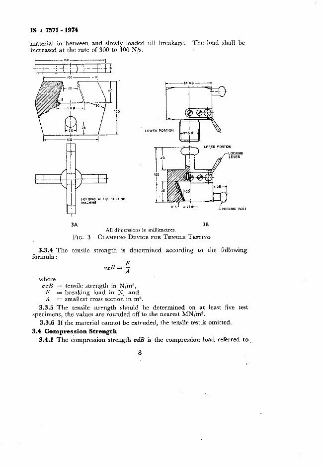
3.3.3 The test pieces are held in the cross clamps (see Fig. 3A) or in the gripping head ( see Fig. 3B) of the tensile testing machine with some soft
7
IS : 7571- 1974
material in between and slowly loaded till breakage. The load shall be increased at the rate of 300 to 400 N/s.
A, “PPER PORTION
,
3A 3B All dimensions in millimetres.
FIG. 3 CLAMPING DEVICE FOR TENSILE TESTING
3.3.4 The tensile strength is determined according to the following formula :
F azB = -
A where
a&? = tensile strength in N/mZ, F = breaking load in N, and A = smallest cross section in m2.
3.3.5 The tensile strength should be determined on at least five test specimens, the values are rounded off to the nearest MN/m2.
3.3.6 If the material cannot be extruded, the tensile test is omitted.
3.4 Compression Strength
3.4.1 The compression strength odB is the compression load referred to
8
IS : 7571- 1974
the unit cross section at which the test piece breaks the load having been increased uniformly, that is, without jerks.
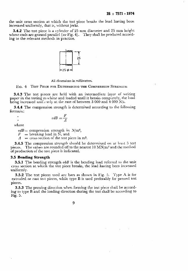
3.4.2 The test piece is a cylinder of 25 mm diameter and 25 mm height whose ends are ground parallel (see Fig. 4). They shall be produced accord- ing to the relevant methods in practice.
All dimensions in millimetres.
FIG. 4 TEST PIECE FOR DETERMINING THE COMPRESSION STRENGTH
3.4.3 The test pieces are held with an intermediate layer of writing paper in the testing m.+chine and loaded until it breaks completely, the load being increased umf ~mly at rhe rate of between 3 000 and 4 000 N/s.
3.4.4 The compression strength is determined according to the following formula :
F ad!3 =-
A
where
adB= compression strength in N/m2, F = breaking load in N, and A = cross section of the test piece in m2.
3.4.5 The compression strength should be determined on at least 5 test pieces. The values are rounded off to the nearest 10 MN/m” and the method of production of the test piece is indicated.
3.5 Bending Strength
3.5.1 The bending strength obB is the bending load referred to the unit cross section at which the test piece breaks, the load having been increased uniformly.
3.5.2 The test pieces used are bars as shown in Fig. 5. Type A is for extruded or cast te<t pieces, while type B is used preferably for pressed test
pieces.
3.5.3 The pressing direction when forming the test piece shall be accord- ing to type B and the loading direction during the test shall be according to Fig. 5.
9

2b= 81
All dimensions in millimetres.
Type A With Round Cross Section Type B With Flattened (Oval) Cross Section
(The Arrow indicates the Direction of Pressing and Loading)
FIG. 5 TEST PIECE FOR DETERMINING THE BENDING AND IMPACT BENDING STRENGTH
3.5.4 The supports in the bending testing machine shall be two steel rollers of 10 mm diameter spaced at 100 mm between their axes (supporting width L). The load shall be applied over a third steel cylinder of 10 mm diameter oxi the middle of the test piece and increased till the latter breaks, the rate of increase being about 50 N/s.
3.5.5 The bending strength is determined according to the following formula :
FL ubB = Tp
where ubB= bending strength in N/m2, F = breaking load in N, L = supporting width in m, and/ W = moment of resistance in m3.
3.5.6 The resistance moment for type A test piece is
W+PwO.M
3.5.7 For type B test pieces, the moment of resistance may be calculate J by assuming roughly that the test piece has an elliptical cross section wit’; the semi-axes a and b (see Fig. 5). The moment of resistance is~:
W = z a26 w 0.8 a26 4
10

IS : 7571- 1974
3.5.8 The bending strength should be determined on at least 5 test pieces. The values shall be rounded off to the nearest MN/m2. The test report should contain an indication of the method of production.
3.6 Impact Bending Strength
3.6.1 The impact bending strength an is the impact work referred to the unit cross section at which the test piece subjected to impact bending stress breaks.
3.6.2 The test pieces are bars according to 3.5.2.
3.6.3 The direction of pressing when forming the test piece shall be according to type B and the direction of impact in the testing shall be accord- ing to Fig. 5.
3.6.4 The impact bending strength is calculated according to the follow- ing formula :
A an= -
F
where
?? = impact bending strength in kJ/m2, = impact work of the pendulum hammer in kJ, and
F =I cross section of the bar (not the break face area) in rn”.
3.6.5 The impact bending strength should be determined on at least five test pieces and expressed to the nearest 0.1 kJ/m”.
3.7 Elasticity Modulus
3.7.1 The elasticity modulus (E) is the mechanical stress referred to unit ’ area, N/m”, at which the original length of the body would have doubled.
3.7.1.1 The reciprocal of the elasticity modulus is termed the strain coefficient or elongation coefficient (m2/N).
3.7.2 The test piece is a round bar of 16 mm diameter and 500 mm length. .The test piece is formed by extrusion.
3.7.3 The test piece is supported on two knife edges separated by 40 cm (r = 1 mm.). The bar is then loaded in its centre without any jerks, the pressure being transmitted by a steel blade (r = 10 mm).
3.7.4 In this determination, the bending of the test bar is first calculated. From the bending, the elasticity modulus is calculated according to the following formula :
EJ3.(P-Po) 48.J.f
&here E = elasticity modulus in N/m2, I = distance between the supports in m,
11
1s : ‘15’11- 1974
P-P,, = load reduced by the initial load in N, .7 = moment of inertia in m4, and f = bending of the bar in the middle in m.
3.7.5 Test shah he carried out on three test pieces all of which shall pass the test.
3.8 Shear Modulus (Modulus of Rigidity)
3.8.1 The elastic shear is the ratio of the length by which a surface shifts with respect to another parallel surface under the action of a shear stress (N/ms) to the distance between the two surfaces.
3.8.1.1 The shear coefficient (m2/N) is the ratio of the elastic shear to the acting shear stress.
3.8.1.2 The reciprocal of the shear coefficient is termed as shear modu- lus, N/m2.
3.8.2 The shear modulus is calculated from the twist angle in the test of the torsion strength.
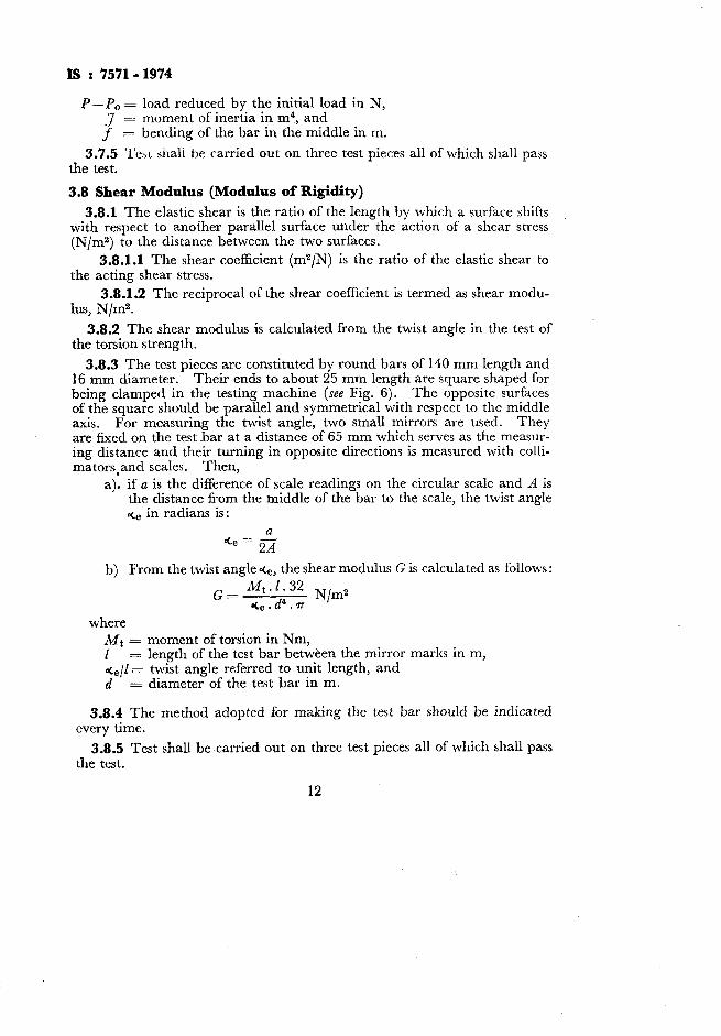
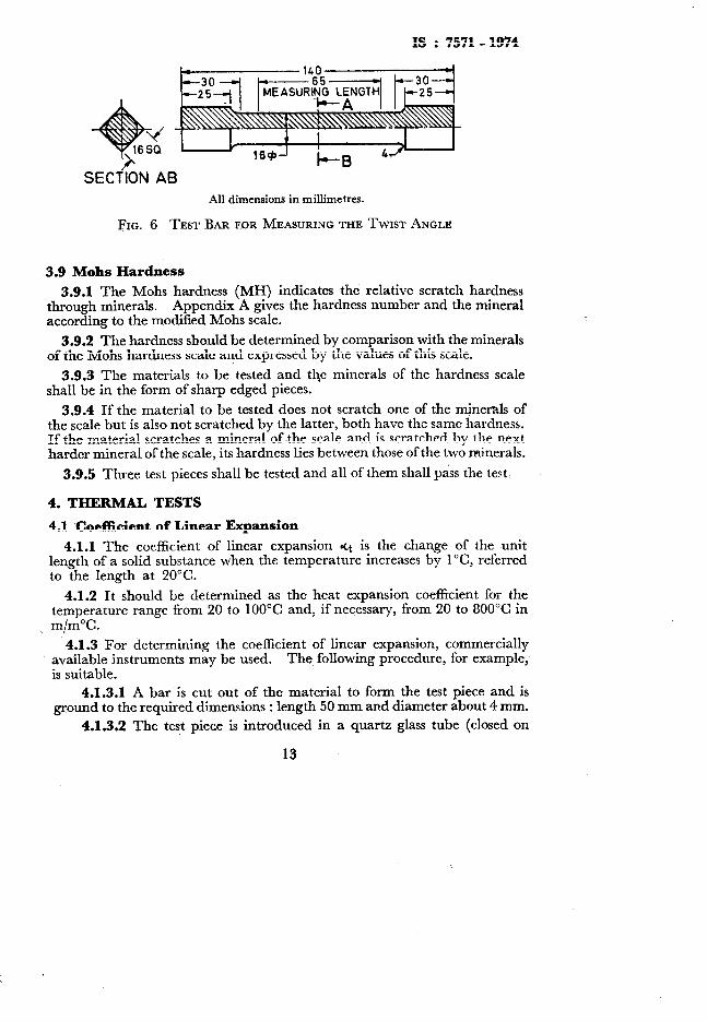
3.8.3 The test pieces are constituted by round bars of 140 mm length and 16 mm diameter. Their ends to about 25 mm length are square shaped for being clamped in the testing machine (see Fig. 6). The opposite surfaces of the square should be parallel and symmetrical with respect to the middle axis. For measuring the twist angle, two small mirrors are used. They are fixed on the test bar at a distance of 65 mm which serves as the measur- ing distance and their turning in opposite directions is measured with colli- mators,and scales. Then,
a), if a is the difference of scale readings on the circular scale and A is the distance from the middle of the bar to the scale, the twist angle ace in radians is:
b) From the twist angle eCe, the shear modulus G is calculated as follows :
G= ‘~‘~~“f N/m2 e- *
where Mt = moment of torsion in Nm, I = length of the test bar between the mirror marks in m, de/l = twist angle referred to unit length, and d = diameter of the test bar in m.
3.8.4 The method adopted for making the test bar should be indicated every time.
3.8.5 Test shall be carried out on three test pieces all of which shall pass the test.
12
IS : 7571
SECTION A6 All dimensions in millimetres.
FIG. 6 TEST BAR FOR MEASURING THE TWIST ANGLE
~3.9 Mohs Hardness
- 1974
3.9.1 The Mohs hardness (MH) indicates the relative scratch hardness through minerals. Appendix A gives the hardness number and the mineral according to the modified Mohs scale.
3.9.2 The hardness should be determined by comparison with the minerals of the Mohs hardness scale and expressed by the values of this scale.
3.9.3 The materials to be tested and the minerals of the hardness scale shall be in the form of sharp edged pieces.
3.9.4 If the material to be tested does not scratch one of the minerals of the scale but is also not scratched by the latter, both have the same hardness. If the material scratches a mineral of the scale and is scratched by the next harder mineral of the scale, its hardness lies between those of the two minerals.
3.9.5 Three test pieces shall be tested and all of them shall pass the test.
4. THERMAL TESTS
4.1 Coeflicient of Linear Expansion
4.1.1 The coefficient of linear expansion et is the change of the unit length of a solid substance when the temperature increases by l”C, referred to the length at 20°C.
4.1.2 It should be determined as the heat expansion coefficient for the temperature range from 20 to 100°C and, if necessary, from 20 to 800°C in
\ m/m%.
4.1.3 For determining the coefficient of linear expansion, commercially available instruments may be used. The following procedure, for example,, is suitable.
4.1.3.1 A bar is cut out of the material to form the test piece and is ground to the required dimensions : length 50 mm and diameter about 4 mm.
4.1.3.2 The test piece is introduced in a quartz glass tube (closed on
13
IS : 7571 - 1974
one side) of an electric heater and pressed against the inside bottom of the tube with a quartz glass rod which is adjacent to the test piece. The expansion of the test mete is transmitted through the Quartz rod on to a dial gauge which has a scale division of 1 /l 000 mm. The apparatus is arranged horizontally. Near the test piece there is a thermoelement to measure the temperature.
4.1.3.3 The increase of temperature during the entire measurement is 25°C in 5 minutes. The elongation is read off in microns with every tem- peraturc increase of 25°C and for ea.ch temperature read, the elongation is expressed in percentage of the initial length at room temperature.
4.1.3.4 The expansion of the quartz glass parts is taken into account by introducing a correction factor. l’his correction is either indicated on the apparatus or else determined by a test with the measuring body of known heat expansion.
4.1.3.5 By the addition of the percentage quartz glass correction to the percentage elongation, the actual percentage increase a of the test piece may be obtained. From this, coefficient of heat expansion is determined as follows :
where
<t = mean linear heat expansion coefficient in 10e6 m/m% for the temperature range from the initial temperature to the measuring temperature, and
t = difference betw-een the initial temperature and the measuring temperature.
4.P.4 The form of the test piece is suitably chosen according to the testing apparatus used.
4.1.5 Test shalt be carried out on three test pieces all of which shall pass the test.
-4.2 Specific Heat
4.2.1 The specific heat c of a material is that quantity of heat in kcal which is necessary to increase the temperature of 1 kg of this material by 1°C.
4.2.2 It is determined as the mean specific heat cm for the temperature range fr~om 20 to 100°C and, if necessary, from 20 to 800°C in J/kg”C.
4.2.3 For determining the specific heat, commercial appliances are used.
4.2.4 The shape of the test piece is chosen suitably according to the testing apparatus used.
4.2.5 Test shall be carried out on three test pieces all of which shall pass the test.
14

IS : 7571.1974
4.3, Thermal Conductivity
4.3.1 The thermal conductivity indicates by a numerical value the number of degrees by which the mean temperature of a cube of 1 m side increases when the temperature drop of two opposite sides differs by 1 “C/m.
4.3.2 It is determined as a mean thermal conductivity a, in ms/h for the region of temperature from 20 to 100°C.
4.3.2.1 A ceramic plate at 20°C is heated on a liquid metal layer at a known temperature. Using a stop-watch, measure the time taken for the non-heated side to attain a certain temperature.
4.3.3 The thermal conductivity should be determined on at least 3 test pieces to an accuracy of l/10 000 ms/h.
4.4 Heat Conductivity
4.4.1 The heat conductivity h indicates the number of kcal passing steadily through a cross section of 1 ms of a 1 m thick slab in one hour when the temperatures on the opposite sides of the slab are at a difference of 1°C.
4.4.2 The heat conductivity should be determined as the mean heat con- ductivity between 20 and 100°C and, if necessary, for other ranges like 100 to 3OO”C, 300 to 600°C and 600 to 800°C.
4.4.2.1 For determining the mean heat conductivity between 20 and lOO”C, commercial apparatus shall be used.
4.4.3 The shape of the test piece is chosen suitably ‘according to the apparatus used.
4.4.3.1 The arrangement may, for example, consist of 7 test pieces placed one over the other, the heat flow through the wooden cylinder heated from inside being measured perpendicularly to the axis of the cylinder.
4.4.4 The heat conductivity up to 100% may also be calculated from the thermal conductivity according to 4.3, the specific heat according to 4.2 and the volumetric mass according to 3.2.
NOTE -This calculation is particularly suitable for rapid routine investigation but cannot replace the direct determination of the heat conductivity.
4.4.5 The heat conductivity is calculated according to the following formula :
h = 1000acy
where A = heat conductivity in W/m%, a = thermal conductivity in ms/h, c = specific heat in J/kg%, and y = volumetric mass in kg/ms.
4.4.5.1 In this method of calculation, the specific heat should be inserted as mean value c, accordingit 4.2 and the thermal conductivity as
15

IS : 7571 - 1974
mean value a, according to 4.3 between 20 and 100°C. For the heat con- ductivity, a mean value A,,, between 20 and 100°C may also be obtained.
4.5 Refractoriness, Seger Cme Drop Point
4.5.1 The refractory property is determined. as the cone melting point in comparison to small seger cones. Small scgr~~ cones arc about 2.5 cm high.
4.5.2 The test pieces shall have the same shape and size as the small seger cone.
4.5.3 The test pieces are heated along with the seg : cones in an electric coal grit-resistance furnace until complete collapsing or bending of the test piece takes place, in the latter case the test piece iightly touches its base support.
4.5.3.1 The seger cone should be :jo @aced :Lt -he shortest edge is vertical (see Fig. 7).
i 90”
FIG. 7 SEGER CONE
4.5.3.2 For a correct assessment of the refractory property several determinatrons have to be affected. One of them should be with the next seger cone and two more with the seger cones that are just lower and just higher respectively to the test piece. These two determinations are con- sidered completed if the next higher or next lower seger cone has gone down.
4.5.3.3 After the test, it shall be evident -from the melted specimen that the heating has been uniform over the entire height of the specimen. There should not be single-side heating, nor an advance of the tip or of the base. Such wrong melted specimens should be rejected.
16

is : 7571- 1974
4.5.3.4 Above the seger cone 26 (code number 158 according to a melt- ing point of 1 580”), the furnace should be heated such that the increase of temperature from cone to cone takes place in at least 5 and at the most 10 minutes.
4.5.4 The refractory property corresponds to the seger cone whose condi- tions corresponds to that of the test piece or the refractory property of the test piece between those of two consecutive seger cones.
4.5.5 The refractory property is designated by the number of the corres- ponding seger cone, for example, 33 (code number 173 corresponding to .a melting point of 1 730”)) or the numbers of two successive seger cones may be given, for example, 33134 (code number 1731175 corresponding to a melting point of 1 730”/1 750“), when refractory property ofthe test piece lies between two seger cones. No other designations shall be allowed.
4.56 The test method is applicable for determinations up to seger cone 42.
4-5.7 Test shall be carried out on three test pieces all of which shall pass the test.
5. CIIFMICAL TESTS
5.1 Resistance to Corrosion
5.1.1 Resistance to corrosion is the resistance to chemical attack.
NOTE - Ceramic materials are generally resistant to atmospheric corrosion even in the presence of salt, acid and alkali containing gases, water vapour and rain; the only excep- tion being hydrofluoric acid.
5.1.2 Test Procedurefor Testing the Corrosion Resistance of Ceramic Materials
5.1.2.1 The total surface of each specimen is determined correct to 2 percent. The test specimen and comparison specimen are thoroughly cleaned by hand, brush or ‘clot cloth and water at room temperature. No chemical cleaning agent should be used. Then they are both rinsed with distilled water and finally with ethanol. They are then dried together in the hot chamber for 45 minutes at 15O”C, then placed for 45 minutes in a desiccator to cool down. The desiccator should be near the balance so that immediately after cooling, the mass of the two specimens may be determined. The difference between their masses n GI is determined correct to 0.1 mg.
5.1.2.2 The next day, 500 to 600 ml of the hydrochloric acid (20.4 percent m/m) is heated in the beaker.
X1.2.3 The test piece is suspended in the acid with platinum wire so that it is covered on all sides by the boiling acid.
5.1.2.4 After 6 hours the specimen is removed from the acid and thoroughly rinsed with distilled water. with acid) is similarly rinsed.
The comparison piece (not treated
5.1.2.5 The two specimens are then dried at 150°C as described
17

IS : 7571- 1974
in 5.1.2.1, cooled and their masses determined. The mass difference AG, between the specimensis determined correct to 0.1 mg.
NOTE - It is very important to observe this condition both times.
5.1.2.6 The determination is effected in the same way with a second specimen.
5.1.2.7 The difference in the two masses divided by the area of the
surface of the specimen aG, -nG, A
gives the mass loss per unit area in
mg/dm2. If the results deviate by more than 10 percent from their average, then the test is repeated second time.
5.1.2.8 ~The average of the mass loss per unit surface is divided by 2. This value then indicates the acid class to which the specimen belongs.
5.1.3 When giving the test results, indicate whether the piece used for the test was glazed or unglazed.
5.1.4 Test shall be carried out on three specimens all of which shall pass the test.
6. ELECTRICAL TESTS
6.1 Dielectric (Puncture) Strength
6.1.1 The electric puncture voltage (Ua) is the effective value of sinusoidal voltage at which the puncture takes place.
6.1.2 The electric puncture strength (dielectric strength) (Ed) is the quo- tient of the puncture voltage (U,) and the minimum thickness (a) of the test piece measured between the electrodes. A uniform field strength at the place of measurement is assumed.
6.1.2.1 The dielectric strength is not any specific property of the material. It may be dependent on the thickness of the test piece, the voltage and the time of application of the voltage.
6.1.3 The measurement is carried out at 2755°C. To avoid pre’dis- charge, the test pieces are tested under oil. The measurement is carried out with alternating voltage at 50 Hz. The peak factor should be between 1.34 and 1.48 (that is, &?f5 percent). trodes should preferably be earthed.
One of the two measuring elec-
6J.4 The test piece is an unglazed flat plate of 80 mm diameter and 8 to 10 mm thickness with a cup shaped depression on one side (see Fig. 8). This depression should be made in the dried body before it is burnt. The dia- meter of the depression shal: be 20 mm, the thinnest portion of the plate between the lowest point of the cup and the opposite plane surface shall be 1.5 mm & 10 percent. To obtain this dimension it may be necessary to grind the test piece on the flat side after being burnt. The depression and the opposite surface should be metallized in the burning process.
6.1.4.1 The test piece may also be in the form of tubes or plates up to
18

IS : 7571- 1974
All dimensions in millimetres.
FIG. 8 TEST PIECE FOR DETERMINING THE DIELECTRIC STRENGTH
3 mm thickness if the material is not suitable for making larger plates (80 mm diameter).
6.1.5 The voltage is increased quickly to about half the expected puncture voltage, then at the rate of 0.5 to 1 kV every second until puncture.
6.1.6 The minimum thickness (u) taken as basis for the dielectric strength should be determined immediately before or after the measurement of the puncture voltage at the thinnest portion of the test piece (without considering the path of the puncture) preferably to an accuracy of 2 percent.
6.1.6.1 With the help of Fig. 9, the factor /3 for calculating the dielectric strength may be obtained (for the test piece shown in Fig. 8) from the mea- sured smallest thickness.
&J = ud. j3 kVlcm
The following points have been plotted in Fig. 9 : a : Is
mm 1.0 10.68
;:; 7.35 5.69
3.0 4.03 4.0 3.21 5.0 2.72
19

MINIMUM THICKNESS (a) mm
FIG. 9 CONVERSION FACTOR /3 IN THE MEASUREMENT OF THE PUNCTURE VOLTAGE OF TEST PIECES ACCORDING TO FIG. 8
6.1.7 The dielectric strength should be determined on at least 5 test pieces. The values shall be rounded off to the nearest kV/cm. The method of production should also be indicated. The test shall be carried out only oncompact materials.
6.2 Dielectric Constant and Dissipation
6.2.1 General
Factor
6.2.1.1 The relative dielectric constant (Ed) of an insulating material
20
IS : 7571- 1974
is the quotient of the capacitance of a condenser at which the space between the electrodes is completely occupied by the insulator (Cx) and the capaci- tance (C,) of the same electrode arrangement in the air.
6.2.1.2 The dielectric loss tangent or dissipation factor (tan S) of a material is the tangent of the shift angle by which the phase shift between the current and voltage in the capacitor deviates from al.2 when the dielec- tric of the capacitor is exclusively made up of the insulator.
6.2.1.3 The loss coefficient is the product of dielectric constant and dielectric loss tangent (or dissipation factor).
6.2.2 Apparatus
6.2.2.1 The following test apparatuses are required:
a)
b)
An alternating voltage source with the frequency necessary for the measurement.
A measuring arrangement permitting to express capacitance of the amount Cx to an accuracy of at least (0.01 C&l pF) and the dielec- tric loss tangent of the amount 5 to an accuracy of at least (0.05 <+ 0.1 X 10⁻³).
An electrode arrangement in which the test piece is located between the electrodes in a, as far as possible, homogeneous or otherwise defined electric field.
Since the measuring equipments are of various types, the same form of the test piece will not be sufficient for the entire range of measurement from 15 to 10 000 Hz. plates are used.
Up to a frequency of 5 MHz The rule for the size of the electrode area is that
the capacitance C, of the electrode arrangement shall be not less than 70 pF.
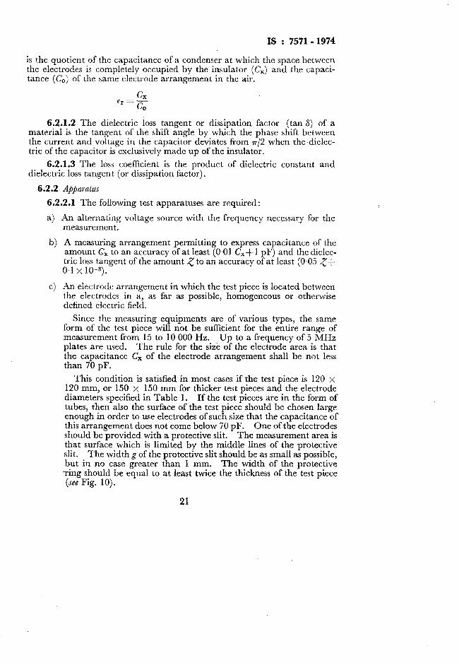
This condition is satisfied in most cases if the test piece is 120 x 120 mm, or 150 x 150 mm for thicker test pieces and the electrode diameters specified in Table 1. If the test pieces are in the form of tubes, then also the surface of the test piece should be chosen large enough in order to use electrodes of such size that the capacitance of this arrangement does not come below 70 pF. One of the electrodes should be provided with a protective slit. The measurement area is that surface which is limited by the middle lines of the protective slit. The width g of the protective slit should be as small as possible, but in no case greater than 1 mm. The width of the protective ring should be equal to at least twice the thickness of the test piece (see Fig. 10).
21

IS : 7571- 1974
TO VOLTAGE SOURCE
FIG.
4
e)
f >
PROTEC; ‘Gtkd2-~:OTECTED ELECtRODiZ
TO MEASURING APPARATUS
10 CIRCULAR PLATE ELECTRODE WITH GUARD RING FOR TEST PIECES IN THE FORM OF PLATES
For measurements that are to be carried out in the frequency range of 1 to 100 MHz with plate electrodes, plates up to 5 mm thickness are suitable as test pieces. Their diameters should be as far as possible, equal to the diameter of the electrodes but may also be smaller. The capacitance of the test piece shall preferably be not less than 15 pF and not more than 80 pF. The electrodes shall be applied without protective ring.
For measurements in the frequency range from 60 to 10 000 MHz, cylindrical test pieces are used. For the range from 60 to 4 000 MHz, the test pieces are provided with a bore. In the region from 4 000 to 10 000 MHz in which hollow conductors are used, the bore of the cylindrical test piece is omitted. The length L of the test piece shall be so chosen that at least one-quarter of the wave lengths is in the test piece; it may also be an odd multiple of this value.
The electrodes are of metals which are burnt on to the surface of the insulator Instruments for measuring the thickness of the test piece accurate to 2 percent of the thickness+O.005 mm and the dimensions of the electrodes (for calculating the measuring area) correct to 1 percent. Chamber in which the air may be set to required conditions for the preliminary treatment and, if necessary, the testing of the test pieces. It should be possible to maintain the temperature accurate to 2°C and the relative humidity to 5 percent inside the chamber. Thermostat with a temperature setting range from $20 to + 150°C to an accuracy of 2°C in the measurement of the dependancy on temperature of the relative dielectric constant and the dielectric loss tangent.
22

3s : 7571- 1974
TABLE 1
NOMINAL MEASURING
SURFACE
(1) cm*
5
2
-- ELECTRODE DIAMETERS FOR TEST PIECES
THICKER THAN 120 man
mm 24.2 49.5 99.9
[Chm 6.2.2.1 (c)]
MEASURING SURFACE
DIAMETER 6, d,+g
(4) mm mm mm
25.2 : 50.5 :a0 1 100.9 10
6.2.3 Preliminary Treatment of the Test Piece
6.2.3.1 Preliminary treatment to achieve a particular initial condition of the test piece - The test pieces are generally dried for a period of4 hours in a desic- cator or a flat vessel with suitable drying agent.
6.2.3.2 Preliminary treatment to determine action of heat - The measurements are carried out after 24 hours at room temperature after storage in heat for specific time. The test pieces should be first dried and then. brought to the measurement temperature in the hot or cold chamber in dry air.
6.2.3.3 Preliminary treatment for determining the action of moisture - The following treatments in increasing order of severity are included :
a) Keeping in air at 65, 80 or 90 percent relative humidity and room temperature;
b) Keepingin air of approximately 65 or 90 percent relative humidity and at higher temperature, 40f2”C is recommended;
c). Keeping in distilled water at room temperature (after removing the test piece from the water-bath, the water adhering to the surface is removed with non-fibrous filterpaper) ; and
d) Keeping in a flow of water vapour (after this any water on the sur- face is removed with non-fibrous filter paper).
6.2.4 Test Procedure
6.2.4.1 If a preliminary treatment of the test piece according to 6.2.3 is provided, the thickness of the test piece is first determined correct to 2 per- cent, the electrode is then applied and finally the preliminary treatments of the test piece are carried out. Within latest 2 minutes after the comple- tion of the preliminary treatment, the measurements are carried out for determining the relative dielectric constant and the dielectric loss tangent.
6.2.4.2 Unless agreed otherwise, the measurements are carried out at 27fYC and 65&5 percent relative humidity.
6.2.5 Assessment
6.2.5.1 Relative dielectric constant Q - The relative dielectric constant
23

IS : 7571- 1974
cr is found out from the measured capacitance C, and the capacitance of the electrode arrangement in air C,. If the capacitance C, is measured without the protective ring it contains also the capacitance component C, which takes into account the boundary field and a capacitance component C, which depends on the stray field. The corrected capacitance of C, is obtained as :
cIx=C* - C, - C, pF For the individual electrode arrangements, the values C, and C, may be.
calculated according to Table 2 and, therefore, the limit measuring error, if they are neglected, may be estimated.
The capacitance of the electrode arrangement in air C, may be determined either by the measurement of the capacitance at the electrode arrangement in air or by calculation. If C, is measured, the same corrections as in Table 2 shall be applied as for the capacitance C, so that the corrected capacitance of C, is obtained as :
C’o = c, - c, - Cg
The formulae for the calculation of C,, for the individual electrode arrange- ments shall also be taken from Table 2.
Ed is given by :
6.2.5.2 Dielectric loss tangent (tan 6) - The dielectric loss tangent (tan 6) is calculated from the values measured with the apparatus given below and is expressed in 10~~.
‘a) Description - The circuit (see Fig. 11) consists of the following :
1)
2)
3)
4)
5)
6)
A guard ring capacitor for the test piece with the shielded capa- citance C,s and the loss tangent tan 6,. Here a series circuit of a loss-free capacitance with a_resista’nce has been assumed as equivalent circuit. A solid reference capacitor (capacitance C,) which should be as loss-free as possible (air condenser). A purely resistive (non-inductive) four decade resistance box R,[lO x 1OOQ + 10 x 1OQ + 10 x Ifi + 10 x O.IQ + 0.192)
(potentiometer wire)]. A solid non-inductive resistance R, for 50 Hz ineasuremcmt, as
a rule 318.3 Sz = 1 000 -a with parallely connected three decade
capacitance box C, zor example, 11 x 0.1 PF + 11 x 0.01 PF + 11 x 0.001 I_~F + 0.001 I_LF (variable air condenser)]. A vibration galvanometer VG with electromagnetic or perma- nent magnetic tuning. Shielding and protection against excess voltage.
24

TABLE 2 EVALUATION OF THE RESULTS OF MEASUREMENT
(Clause 6.2.5.1)
a) Determination of C,, C, and z,
ELECTRODE ARRANGEMENT
(1)
Plate Electrodes with Guard Ring
TEST PIECE
L
f
GAPACtrANCE OF THE ELECTRODE
ARRANGEMENT’IK AIR C,
PF (2)
n VI+.&?)2 c,=,-c,-=
n
(4 + .eY 0 .0696 ~ (I
CAPACITANCE COMPONENT OF THE PERIPHERAL
FIELD C, PF
(3)
c, = 0
RELATIVE DIELECTRIC
CONSTANT l r
(4)
Cx El= - C0
Plate Electrodes without Guard Ring i) Electrode Diameter -= Test Piece
Diameter
TEST PIECE
r’
For electrode thickness tQ LI (electrode very thin):
(0,058 Zg- ‘z+
0.0185) =
For electrode thickness t<a (electrode thicker) :
s f
Ce-O.O326?rd, (la 8nd, a +
; a z- 1.305)
z ‘r=(l+.u)l,(l+xl--xl,x
II n .=t
C0 ;. EO. I$- n u
2 C,-C,
z zO.0696 2
l r= c,
2 ii) Electrode Diameter When electrode thickness t n
n <Test Piece Diameter <a, the dielectric cons- :: tant of the test pice is 3 * roughly estimated (c’r).
Then
-I.
i
C,=nd,(O.O58 1,fi {_ a
0.0185 e’,)
iii) Electrode Diameter <Test Piece Diameter <Counter Electrode
When electrode thickness t +z, ‘the dielectric cons- tant of the test piece is roughly estimated (2,). Then
C,=,d,(O.O771,3.8+ a
0.0405 c’r)
Cylindrical Electrodes with Guard Ring c = 0.2416 (I,+g) 0
lg (1+2a)’
T c,=o
When a <da, the rough for- mula is:
C,=O.2782 (l,+gj @iSa) x
f P-4 wrl
z L ‘j G-C, 2 cr= - w CO 2 q;l;:-ical Electrodes without Guard c = 0.24161, 1
0 When -% < -, the di- 1,(11-2.) a+& 10
;r;- electric constant of the
When a<dg the rough for- specimen is roughly esti-
mula is : mated (Or). Then
C,= 0.2782 1s (d;+u) x f&=271 (di+a) x
$[l_$ (e&J @*058l$5;O;:;e;;
When -?- a+& 6
test piece length >2,+10 (1, measure at two different test piece lengths and eliminate peripheral influence by subtraction of the results.
b) Dete rmination of the Stray Capacitance C, The capacitance of an electrode against earth is in first approximation (error limit about&25 percent) :
C,=O.O3 -$- +0.3 a pF
where F = Measurement surface in cm*, h = Mean height in cm above the earthed ground surface, and a = Thickness of the test piece in cm.

As in the Original Standard, this Page is Intentionally Left Blank

FIG. 11 HIGI-I VOLTAGE SCHERING BRIDGE
b) Measurement - By gradually increasing the sensitivity of the vibra- tion galvanometer that has been .tuned to resonance, adjust first R, up to minimum deflection then C4, repeating the process alternately till there is no further reduction of the I/‘G deflection.’ Check that with commuted VG the deflection does not alter. If there is a’small alteration, again adjust to zero deflection and average the results, Larger deflections after commuting are reduced by removing the magnetic disturber. Disturbance is caused by all current, carrying untwisted ac lines, transformers, etc. They should, therefore, be shielded.
. c) Evaluation - In the balanced state of the bridge
4 c,, = c, . R- ** (1)
tan 8, = R,s.w.C,+ tan 6, * - (2) when C, is subject to loss and has the loss angle St.
The potentiometer bridge according to Fig. 12 with the poten- tiometer wires (slide loops) a and b is more simple in input, as particularly for C, a solid capacitor may be chosen. Slide loops a and b are so calibrated that
Cls= C,.a * - (3) When a is at the same time a factor that may be read off at tk;o position of the loop contact.
tan 6, is read off directly from the position of the loop contact at 6.
27
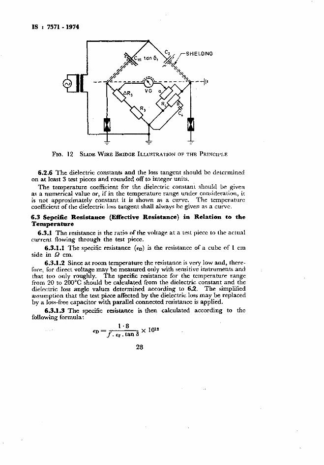
Frb. 12 SLIDE WIRE BRIDGE ILLUSTRATION OF THE PRINCIPLE
6.2.6 The dielectric constants and the loss tangent should be determined on at least 3 test pieces and rounded off to integer units.
The temperature coefficient for the dielectric constant should be given as a numerical value or, if in the temperature range under consideration, it is not approximately constant it is shown as a curve. The temperature coefficient of the dielectric loss tangent shall always he given as a curve.
6.3 Sepcific Resistance (Effective Resistance) in Relation to the Temperature
6.3.1 The resistance is the ratio of the voltage at a test piece to the actual current flowing through the test piece.
6.3.1.1 The specific resistance (on) is the resistance of a cube of 1 cm side in s2 cm.
6.3.1.2 Since at room temperature the resistance is very low and, there- fore, for direct voltage may be measured only with sensitive instruments and that too only roughly. The specific resistance for the temperature range from 20 to 200°C should be calculated from the dielectric constant and the dielectric loss angle values determined according to 6.2. The simplified assumption that the test p&e affected by the dielectric loss may be replaced by a loss-free capacitor with parallel connected resistance is applied.
6.3.1.3 The specific resistance is then calculated according to the following formula :
1.8 ED = f .rr.tanS
x IO=
28

IS : 7571- 1974
where
En - specific resistance in iR cm, j = frequency in Hz, Er - relative dielectric constant, and
tan S= dissipation factor.
6.3.2 Measurements at temperatures 300°C and above are provided only for insulators. The resistance with alternating voltage at 50 Hz is deter- mined from the current and the voltage, using an ammeter of sufficient sen- sitivity to measure the current in the insulation and a voltmeter.
6.3.2.1 When calculating the specific resistance from the measured impedance, the reactive current taken by the test piece may be neglected since at high temperature it is very small compared to the active current. The impedance, therefore, corresponds in rough approximation to the ac resistance.
6.3.3 The test pieces are flat round plates of a diameter about 40 mm and thickness about 3 mm. The material of the electrode is silver or platinum which is burnt on in a permanent fashion to the surface of the test piece. Silver electrodes are suitable only for measuring ranges up to 600°C.
6.3.4 An electric stove is used for heating the test piece. The stove space should be large enough to assure a uniform temperature of the test piece. The heating and cooling rates should be so adjustable that the stove tem- perature increases or decreases by 200 to 300°C per hour. The temperature of the test piece is measured with a thermoelement whose hot junction is positioned in the immediate neighbourhood of the test piece. The mea- suring voltage is applied to the electrodes through platinum wires or strips which are pressed on to the electrodes with a.force of at least 0.5 N. The measurement is taken both during the heating as well as during the cooling. The calculation is based on the mean value of the resistance measurements during heating and cooling.
6.3.5 The resistance should be determined on at least two test pieces and indicated for 20, 200,400, 600 and, if necessary for 800 and 1 000°C.
6.4 Surface Resistivity
6.4.1 The surface resistivity is the quotient of the applied voltage and the current flowing over the surface per unit width of the surface. It gives an indication of the condition of insulation at the surface of an insulating material which is liable to be altered by external influences like moisture, impurities, chemicals.
6.4.1.1 Since the measurement of the surface resistivity comprises not only the resistance at the surface of the insulating material but partly also that of the insulator, the specific surface resistivity has to be calculated separately.
29

6.4.2 The test pieces may be flat plates, bars or tubes whose surface should not be altered, damaged or machined.
6.4.3 The electrodes are two graphite or precious metal strips of 100 mm length with a spacing of lO+O.l mm between them.
6.4.4 The surface current is -measured with a galvanometer one minute after applying a dc voltage of 1 000 V.
6.4.4.1 The surface resistivity R, is given by Ohm’s law.
6.45 The measurements shall preferably be carried out in an air controlled chamber immediately after the preliminary treatment since after the removal of the test piece from this chamber the moisture at the surface and hence the surface resistivity may also alter considerably.
6.4.6 The surface resistivity RO is determined on three test pieces and expressed in ohms.
6.5 Arc Resistance
6.5.1 The test is for determining to what extent the insulating material particip.ates in the carrying of the current or is materially altered either permanently or temporarily under the action of the arc.
6.5.2 Testing Apparatus
a) Electrodes - Two pure carbon rods of 8 mm diameter. h) Arrangement for holding the electrodes at an angle of slightly more
than 90” with respect to each other in a plane at 60” to the horizontal a on the horizontal test piece, and moving the electrodes away from *each other at a speed of 1 mm/s.
c) dc voltage source of 220 V. d) Resistance connected in series of 10 ohms.
6.5.3 Taking, Preparation and Shape of the Test Piece-These shall be according to the relevant standards on the insulating material. The test piece is a plate of 120 x 120 mm.
6.5.4 Test Procedure
6.5.4il The electrodes are placed on the horizontal test plate with an arrangement according to 6.5.2(b). A resistance of 20 ohms is connected in series to the electrodes and a dc voltage of 220 V is applied. After the formation of the arc between the electrodes, these are withdrawn away from each other with a maximum speed of 1 mm/s and the grade of arcing resis- tance is fixed according to 6.5.4.2.
During the action of the arc the conducting of current is checked by inspection.
After cooling, the electrodes are again placed on the trace left by the arc to check whether a conducting bridge remains in the insulating material.
The arrangement of the electrodes should be such that the gases rising
30

from the arc may freely escape upward. When the current is condu’ctedby insulating material, the arc that generally burns upward disappears in insulator surface that glows and has become partly or fully conducting,
the the
3) : 6.5.4.2 There arc six grades of arc resistance as follows (see alsu Table
Grade L,-- Under the arc which may be slruck to over 20 rnu~lcngth, a conducting bridge is formed in the insulating material which remains conducting even alter cooling. Grade L, - Under the arc which in part cannot be drawn over 20 mm length, a partly conducting bridge is formed in the insulating material which loses its conducting property after cooling. the insulating material cracks.
@cause of the heat,
Grade L, - Under the arc which may he drawn to over 20 mm length, a partly conducting bridge is formed in the insulating material which loses its conducting property after cooling. Grade L, - The arc cannot be struck to its normal length of 20 mm. Under the arc no conducting bridge is formed. Because of the heat, the insulating material splits. Grade L, -- The arc may be struck further than 20 mm, but it does not form any connected bridge in the insulating material. There are also no occurrences as mentioned for Grades L, and L, (cracking or splitting of the insulating material). Grade L, - The arc may be struck above its normal length of about 20 mm, and no continuous conducting bridge is formed in the insulating material. Also there are no occurrences as foi Grades L, and L, (cracking .or splitting of the insulating material).
1s : 75710 1974
TABLE 3 GRADES OF ARCING STRENGTH (OR RESISTANCE)
[Clauses 6.5.4.2 and 7.1 (c)]
GRADE DETERMINATION r--------- * - --- 7 .\rc May be Conducting Bridge in Behaviour of the Insula- Struck Up to Insulating Material ting Material
mm w-7 Under arc After coolirrg
(2) (3)
>20 Yes Partly <20 Partly yes
>20 Partly yes <20 No >20 No <20 No
(4)
Yes
E No No No
(5)
Carbonized or burnt Split
Melted and ‘vaporized - -
31

IS : 7571- 1974
6.6 Maximum Thermal Shock Temperature
6.6.1 Test Piece - The test piece is in the form of a solid cylinder ZOrfi 1 mm long and is prepared by the same process as for production articles.
6.6.2 Method of Test-Heat the test pieces to the first test temperature and maintain at that temperature for at least 30 minutes. Arrange the furnace so that the test pieces may fall freely into a bath of cold running water at 10 to 20°C. Quench the test pieces in this manner for at least five minutes and then examine for cracks with the aid of a dye. If there are no visible signs of failures, replace the test pieces in the furnace and repeat the cycle at a temperature 10°C higher. Repeat the process and state -the lowest temperature at which two or more failures occur as the maximum thermal shock temperature. Commence the test at the temperature which all test pieces will withstand satisfactorily. When the maximum thermal shock temperatux e exceeds 2OO”C, make the temperature increments 25°C.
6.6.2.1 The results shall be stated as maximum thermal shock tempera- ture in “C and the limits shall be agreed between the purchaser and the manufacturer.
6.6.3 Detection of Cracks By Dye Method - Pieces of insulating material shall be immersed in one percent alcoholic solution of fuchsin (1 g fuchsin in 100 g of methylated spirit) under a pressure of not less than 15 MN/m2 for a period such that the product of- the test duration in hours and the pressure in MN/m2 is not less thau 180.
The pieces shall then be removed from the solution, washed, dried and broken. Examination with naked eye of the freshly broken surface shall not reveal any dye penetration. Penetration into small cracks formed during the initial breaking shail be neglected.
7. TEST REPORT
7.1 The test report should contain reference to this standard and the follow- &g information :
a) Type, designation and shape in which the insulating material has been supplied;
b) Preparation, form, dimensions and date of preparation of the test piece;
c) Arcing resistance and grade according to Table 3; and d) Date of testing.
32

rs : 7571 - 1974
APPENDIX A
(Clause 3.9.1)
MODIFIED MOHS SCALE
A-l. HARDNESS NUMBER
A-l.1 l’lle ]mrducss nurrdxx 01’ various ruimxals accorthtg Lo Ihc inodilicd Mohs scale is given below:
Original Mohs Scale Afodijed Mohs Scales r__lh.. ___ ~~ _-~L-_-.--7 Hardness Minerals Hardness Miueral
Number Number
l’alc Gypsum Calcite Fluorite Apatite Orthoclase Quartz Tapus Corundum Diamond
1 2 3 4 .5 6 7 G
1: 11 12
:4” 15
Talc Gypsum Calcite Fluorite Apatitc Orthoclasc Vitreous silica Quartz or stellitc Tapus Garnet Vused zircnnia Fused alumina Silicon carbide Boron carbide Diamond
33

BUREAU OF INDIAN STANDARDS
Headquarters Manak Bhavan, 9 Bahadur Shah Zafar Marg, NEW DELHI 110002 Telephones: 323 0131,323 3375,323 9402 Fax : 91 11 3234062, 91 11 3239399, 91 11 3239382
Telegrams : Manaksanstha (Common to all Offices)
Central Laboratory : Telephone
Plot No. 20/9, Site IV, Sahibabad Industrial Area, Sahibabad 201010 0-77 00 32
Regional Offices:
Central : Manak Bhavan, 9 Bahadur Shah Zafar Marg, NEW DELHI 110002 32376 17
*Eastern : l/14 CIT Scheme VII M, V.I.P. Road, Maniktola, CALCUTTA700054 337 86 62
Northern : SC0 335-336, Sector 34-A, CHANDIGARH 160022 60 38 43
Southern : C.I.T. Campus, IV Cross Road, CHENNAI 600113 235 23 15
tWestern : Manakalaya, E9, Behind Marol Telephone Exchange, Andheri (East), 832 92 95 MUMBAI 400093
Branch Offices::
‘Pushpak’, Nurmohamed Shaikh Marg, Khanpur, AHMEDABAD 380001
SPeenya Industrial Area, 1 st Stage, Bangalore-Tumkur Road, BANGALORE 560058
5501348
839 49 55
Gangotri Complex, 5th Floor, Bhadbhada Road, T.T. Nagar, BHOPAL 462003 55 40 21
Plot No. 62-63, Unit VI, Ganga Nagar, BHUBANESHWAR 751001 40 36 27
Kalaikathir Buildings, 670 Avinashi Road, COIMBATORE 641037 21 01 41
Plot No. 43, Sector 16 A, Mathura Road, FARIDABAD 121001 8-28 88 01
Savitri Complex, 116 G.T. Road, GHAZIABAD 201001 a-71 19 96
53/S Ward No.29, R.G. Barua Road, 5th By-lane, GUWAHATI 781003 5411 37
5-8-56C, L.N. Gupta Marg, Nampally Station Road, HYDERABAD 500001 201083
E-52, Chitaranjan Marg, C-Scheme, JAIPUR 302001 37 29 25
117/418 6, Sarvodaya Nagar, KANPUR 208005 21 68 76
Seth Bhawan, 2nd Floor, Behind Leela Cinema, Naval Kishore Road, 23 89 23 LUCKNOW 226001
NIT Building, Second Floor, Gokulpat Market, NAGPUR 440010 52 51 71
Patliputra Industrial Estate, PATNA 800013 26 23 05
Institution of Engineers (India) Building 1332 Shivaji Nagar, PUNE 411005 32 36 35
T.C. No. 14/l 421, University P. 0. Palayam, THIRUVANANTHAPURAM 695034 621 17
*Sales Office is at 5 Chowringhee Approach, P.O. Princep Street, CALCUTTA 700072
tSales Office is at Novelty Chambers, Grant Road, MUMBAI 400007
*Sales Office is at ‘F’ Block, Unity Building, Narashimaraja Square, BANGALORE 560002
271085
309 65 28
222 39 71
Pnnted at Pnntogaph. New Delhi (1NDIA