is 6767-1 (1972): direct reading pointer indicator type ac ... · is:6767 (part i)-1972 voltmeter...
TRANSCRIPT

Disclosure to Promote the Right To Information
Whereas the Parliament of India has set out to provide a practical regime of right to information for citizens to secure access to information under the control of public authorities, in order to promote transparency and accountability in the working of every public authority, and whereas the attached publication of the Bureau of Indian Standards is of particular interest to the public, particularly disadvantaged communities and those engaged in the pursuit of education and knowledge, the attached public safety standard is made available to promote the timely dissemination of this information in an accurate manner to the public.
इंटरनेट मानक
“!ान $ एक न' भारत का +नम-ण”Satyanarayan Gangaram Pitroda
“Invent a New India Using Knowledge”
“प0रा1 को छोड न' 5 तरफ”Jawaharlal Nehru
“Step Out From the Old to the New”
“जान1 का अ+धकार, जी1 का अ+धकार”Mazdoor Kisan Shakti Sangathan
“The Right to Information, The Right to Live”
“!ान एक ऐसा खजाना > जो कभी च0राया नहB जा सकता है”Bhartṛhari—Nītiśatakam
“Knowledge is such a treasure which cannot be stolen”
“Invent a New India Using Knowledge”
है”ह”ह
IS 6767-1 (1972): Direct Reading Pointer Indicator TypeAc/Dc Electronic Voltmeter, Part 1: Methods of Measurements[LITD 8: Electronic Measuring Instruments, Systems andAccessories]


IS I 6767 (Part I) - 1972
Indian Standard
SPECIFICATION FOR DIRECT READING POINTER INDICATOR
TYPE AC/DC ELECTRONIC VOLTMETER PART I METHODS OF MEASUREMENTS ’
Electronic Equipment Sectional Committte, ETDC 24
Chairman
‘Sa~r Y. VENKATARAMIA~
Members
Representing
Directorate General of All India Radio ( Ministry of Information & Broadcasting )
RESEARCH ENQINEER, ALL INDIA RADIO ( Alternate to Shri Y. Venkataramiah )
ADDITIONAL DIRECTOR Railway Board ( Ministry of Railways ) DEPUTY DIRECTOR STANDARDS
SHRI $‘K L ARORA ELECOMMUNIOATIONS ) ( Alternate )
. . . All India Radio and Electronics Association, Bombay
SHRI R. G. KESWANI ( Alternate ) ( Bombay )
SHRI ARUP CHAUDE~KJRI ( Alternate ) ( Calcutta )
SHRI L. S. V. EASWAR ( Alternate ) ( Madras )
ASSISTANT DIRECTOR, ELECTRICAL Naval Headquarters ENOINEERINQ ( DESIQN )
ASSISTANT DIRECTOR, ELECTRIOAL ENQ~NEERIN~ ( MATERIAL ) ( Alternate )
SERB H. V. BADRINATE Wireless Planning & Co-ordination ( Department of Communications )
Wing
SHRI A. M. JOSRI ( Alternate) SHRI BALRA J BEAN~T Directorate General of Technical Development
( Ministry of Supply, Technical Development & Materials Planning)
( Continued on page 2 )
*Shri Y. Venkataramiah was Chairman for the mecfing in which this standard was finalized.
@ Copyright 1973
INDIAN STANDARDS INSTITUTION
This publication is protected under the Indian Copyright Act (XIV of 1957 ) and reproduction in whole or in part by any means except with written permission of the publisher shall be deemed to be an infringement of copyright under the said Act.
L

IS : 6767 ( Part I) - 1972
( Continued from page 1 )
Members Rgresenting
Bare B. BIZASIN Directorate General of inspection ( Ministry of
SHRI J. M. Bokrm Defence )
All India Instrument Manufacturers’ & Dealers’ Association, Bombay
SHRI N. GANESAN ( Alternate ) DEPUTY D~RECX-OR GENERAL Overseas Communications Service (Department
of Communications ) DXRECTOR ( Alternate )
SHRI B. P. GROSH National Test House, Calcutta S+U S. T. KACZALI Bharat Electronics Ltd, Bangalore
SHRI K. S. KELKAR ( Alternate I ) SERI R. S. MUNDKUR ( Alternate II )
Wo CDR J. S. LAMBA Directorate of Technical Development & Produc- tion ( Air \ f Ministry of Defence 1
SHRI A. V. RAJU SSO II (Alternate) ’ ’ ’ ’ I
COL N. S. MATHUR Police Wireless ( Ministry of Home Affairs ) SHRI R. S. KALE ( Alternate)
SHRI K. P. P. NAIXBIAR Radio Electronics & Television Manufacturers’ Association ( RETMA ), Bombay
SHRI R. K. JAIN (Alternate ) SHRI D. V. PHATAE
&RI T. V. RAMAMURTI
SHRI V. RAMA SU~RAMANYAM
DR RAM PARSHAD
SHRI D. K. SACHDEV SHRI G. B. DIXIT ( Alternate )
SHRI M. SANICARALINGAM
RadpsITransmitters Subcommittee, ETDC 24 : 4,
Safety for Electronic Equipment Subcommittee, ETDC 24 : 3, IS1
Directorate General of Civil Aviation ( Department ~of Civil Aviation )
National Physical Laboratory ( CSIR ), New Delhi; and Electronic Measuring Subcommittee, ETDC 24 : 2, IS1
Equipment
Indian Telephone Industries Ltd, Bangaiore
Directorate General of Supplies & Disposals ( Ministry of Supply, Technical Development & Materials Planning )
SHRI P. T. KRISHNAMACHAR ( Alternate ) SHRI T. V. SRIRANQAN Posts & Telegraphs Board, New Delhi SHRI N. SRINIVASAN, Director General, ISI ( Ex-o@cio Member )
Deputy Director ( Elec tech ) ( Secretary) . L
Electronic Measuring Equipment Subcommittee, ETDC 24 : 2
Convener
DR RAM PA-RSHAD
Members
National Physical Laboratory ( CSIR ), New Delhi
SHRI T. N. GHO~H ( Alternate to Dr Ram Parshad )
SIIHI N. BALASUNDRAM Eastern Electronics, Faridabad
( Continued on pagi 14 )

IS-: 6767 (Part 1) - 1972
Indian Standard .
SPECIFICATION FOR DIRECT READING POINTER INDICATOR
TYPE AC/DC ELECTRONIC, VOLTMETER
PART I METHODS OF MEASUREMENTS
0. FOREWORD
0.1 This Indian Standard (Part I ) was adopted by the Indian Standards Institution on 7 December 1972, after the draft finalized by the Electronic Equipment Sectional Committee had been approved by the Electrotechni- cal Division Council.
0.2 This standard ( Part I ) covers methods of measurements of character- istics of electronic voltmeters of direct reading pointer indicator type operating up to 300 MHz and intended for voltage measurement normally greater than one volt.
0.2.1 This standard applies to complete apparatus only and not to the component parts thereof.
0.2.2 This standard does not cover digital type electronic voltmeter.
0.3 This standard is one of a series of Indian Standards on electronic measuring equipment. Other standards published so far in the series are given on the fourth cover page.
0.4 This standard lays down a single method of measurement for each characteristic so as to achieve the required degree of precision. It is not, however, intended to exclude ather alternative methods of measurement for which necessary measuring equipment may be available and which are of equal or greater precision than the method prescribed in this standard.
0.5 For the purpose of deciding whether a particular requirement of this standard is complied with, the final value, observed or calculated, express- ing the result of a test, shall be rounded off in accordance with IS : 2-1960*. The number of significant places retained in the rounded off value should be the same as that of the specified value in this standard.
*Rules for rounding off numerical values ( re&d ).
3
IS : 6767 ( Part I ) - 1972
1. SCOPE
1.1 This standard ( Part I ) prescribes the conditions and detailed proce- dures for the measurement of performance characteristics of direct reading pointer indicator type ac/dc electronic voltmeter operating up to 300 MHz.
2. TERMINOLOGY
2.0 For the purpose of this standard, the definitions and explanations of terms specified in 2 of IS : 3437-1972” shall apply.
3. GENERAL CONDITIONS FOR MEASUREMENTS
3.0 Unless otherwise specified, measurements shall be made under normal measuring conditions as specified in 3.1 to 3.6.
3.1 Normal Supply Voltage - Rated supply voltage shall be applied to the electronic voltmeter.
3.1.X The voltage applied to the electronic voltmeter shall be held constant within 1-O percent of the rated value during the measurement of the characteristics.
3.1.2 In case of ac mains operation, the voltage shall be applied at the rated frequency. The. harmonic content of ac mains supply voltage shall not exceed 5.0 percent.
3.1.3’ In case of battery operation, primary or secondary batteries of the type and rated voltage as specified by the manufacturer shall be used.
3.2 Standard Atmospheric Conditions for Tests
3.2.1 Unless otherwise specified, all tests shall be carried out under the following atmospheric conditions:
Temperature 15 to 35°C
Relative humidity 45 to 75 percent
Atmospheric pressure 860 to 1060 mbar
3.2.1.1 Where the conditions mentioned~in 3.2.1 havk a significant influence, these shall be kept substantially constant during the tests.
3.2.2 For specific tests which are considered dependent on atmospheric conditions the tests shall be conducted, and in case of doubt, the tests shall be repeated, at temperature of 27 + 1°C and relative humidity of 65 & 2 percent (see IS : 196-1966-l- ).
*General requirements for direct reading pointer indicator type electronic voltmeter (Jrsl revision ) .
tAtmospheric conditions for testing ( revised).
4

IS t 6767 ( Part I ) - 1972
3.23 The electronic voltmeter shall be protected from draughts and direct radiations.
~3.3 Measurements
3.3.1 All measurements shall be made under the conditions mentioned in each clause.
3.3.2 Preliminary Adjustment -‘- The index of the voltmeter having a mechanical zero shall be set to the appropriate mark on its scale. The supply voltage shall then be applied for a time equal to the warm-up time as specified by the manufacturer. In the absence of such informa- tion, this voltage shall be applied for a period of 15 minutes. The electrical zero shall then be adjusted. All the other preliminary adjust- ments specified by the manufacturer shall be carried out. In making measurements, the mechanical zero shall not be altered, but the electrical zero should be re-adjusted before each measurement, if necessary.
3.3.3 Unless otherwise specified in the relevant clauses, all measure- ments shall be carried out within the measuring range.
3.4 Accuracy of Test Set-up - The test set-up employed to carry out measurements in accordance with this standard shall have an accuracy ,of at least one order better than that specified for the quantity under measurement.
3.5 Reporting - The test report should clearly indicate the following:
a) Rated supply voltage and frequency in the case of ac, b) Atmospheric conditions under which tests are carried out, and
c) Accuracy of test set-up.
4. ACCURACY
4.1 Accuracy of DC Voltage Range
4.1.1 The accuracy of different dc voltage ranges of the instrument shall be measured at least at three points, say, at 10 percent, 50 percent and 100 percent of the effective range on each voltage range.
4.1.2 After the preliminary adjustments, a dc voltage from a regulated dc voltage supply unit shall be fed to the electronic voltmeter as shown in Fig. 1. The regulated dc supply unit shall be adjusted so that the desired deflection ( see 4.1.1) in a particular range is obtained on the voltmeter, The corresponding values on the dc voltmeter shall be read. 7
s
c

IS:6767 (Part I)-1972
VOLTMETER
FIG 1 SET-UP FOR CALIBRATION OF DC VOLTAGE RANGES
4.1.3 From these measurements, the accuracy of the electronic volt- meter under test for each dc range shall be computed.
4.2 Accuracy of AC Voltage Range
4.2.1 The accuracy of the different ac voltage ranges of the instrument shall be measured at least at three points, say, 10 percent, 50 percent and 100 percent of the effective range on each voltage range at 50 Hz.
4.2.2 After the preliminary adjustments, a sinusoidal voltage at the supply of frequency of 50 Hz and having distortion less than 1.0 percent shall be applied to the electronic voltmeter under test as shown in Fig. 2. The variable voltage transformer shall be adjusted so that the desired deflection (see 4.2.1) is obtained on the voltmeter. The corresponding value on the ac voltmeter shall be read.
AC VARIABLE _ ISOLATING ELECTRONIC
AC INPUT VOLTAGE TRANSFORMER _ VOLTMETER TRANSFORMER \ UNDER TEST L
AC VOLTMETER
L
FmI 2 SET-UP FOR CALIBRATION OF AC VOLTAGE RANGES 1
IS :4767 ( Part I ) - 1972
4.2.3 From these measurements, the accuracy of the instrument shall be computed for each range.
5. DEVIATIONS OF ELECTRICAL ZEriO
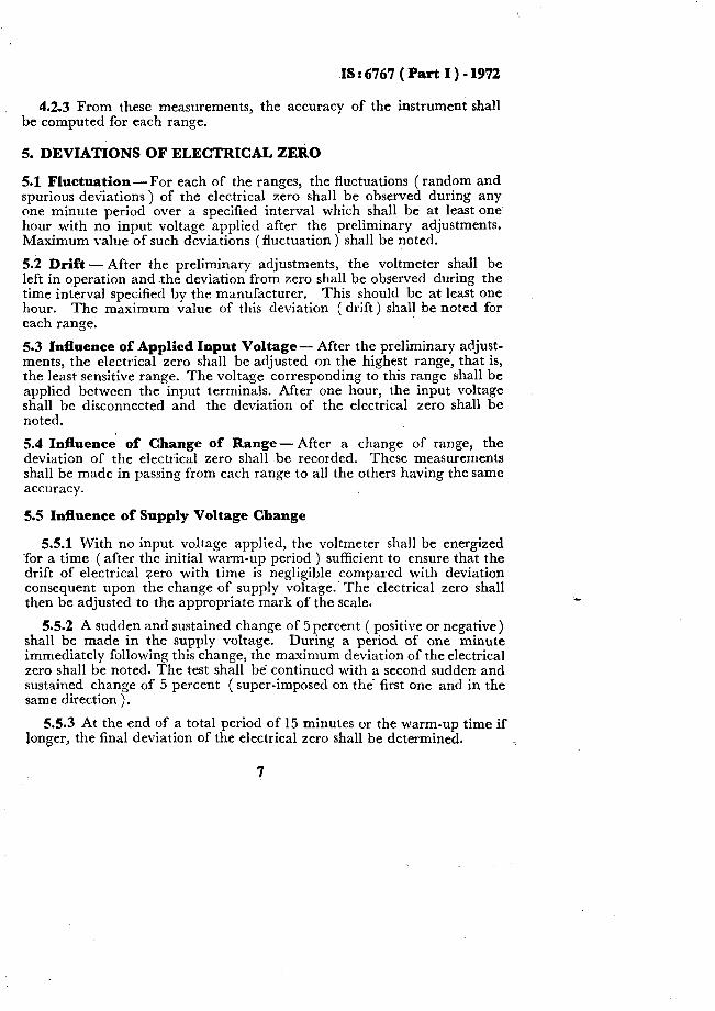
5.1 Fluctuation -For each of the ranges, the fluctuations ( random and spurious deviations) of the electrical zero shall be observed during any one minute period over a specified interval which shall be at least one hour with no input voltage applied after the preliminary adjustments. Maximum value of such deviations ( fluctuation ) shall be noted.
5.2 Drift -After the preliminary adjustments, the voltmeter shall be left in operation and the deviation from zero shall be observed during the time interval specified by the manufacturer. This should be at least one hour. The maximum value of this deviation ( drift) shall be noted for each range.
5.3 Influence of Applied Input Voltage - After the preliminary adjust- ments, the electrical zero shall be adjusted on the highest range, that is, the least sensitive range. The voltage corresponding to this range shall be applied between the input terminals. After one hour, the input voltage shall be disconnected and the deviation of the electrical zero shall be noted.
5.4 Influenck of Change of -Range- After a change of range, the deviation of the electrical zero shall be recorded. These measurements shall be made in passing from each range to all the others having the same accuracy.
5.5 Influence of Supply Voltage Change
5.5.1 With no input voltage applied, the voltmeter shall be energized ~for a time ( after the initial warm-up period ) sufficient to ensure that the drift of electrical zero with time is negligible compared with deviation consequent upon the change of supply voltage.’ The electrical zero shall then be adjusted to the appropriate mark of the scale.
5.5.2 A sudden and sustained change of 5 percent ( positive or negative) shall be made in the supply voltage. During a period of one minute immediately following this change, the maximum deviation of the electrical zero shall be noted. The test shall be continued with a second sudden and sustained change of 5 percent ( super-imposed on the’ first one and in the same direction ).
5.5.3 At the end of a total period of 1.5 minutes or the warm-up time if longer, the final deviation of the electrical zero shall be determined, j
L
7

IS: 6767 ( Part I ) - 1972
5.5.4 The deviation of electrical zero shall be expressed as a percentage of the scale length.
5.5.5 The measurement shall be carried out both for positive voltage -change and for negative voltage change.
5.6 Influence of Ambient Temperature Change
5.6.1 The influence of ambient temperature on the indications of the voltmeter shall be determined from measurements made at intervals of 10 & 1°C within the nominal range. When no nominal range of use con- cerning the ambient temperature is indicated by the manufacturer, this range shall be between two limits respectively equal to 10% above and 40°C below the reference temperature.
5.6.2 After the preliminary ‘adjustments, the voltmeter shall he kept in operation under reference conditions.. The temperature shall be varied in steps of 10°C and deviation of electrical zero shall be measured at each step after thermal equilibrium is reached at that temperature. From these measurements, the total deviation of electrical zero over the specified temperature range shall be computed.
6. VARIATION IN INDICATION
6.1 Influence of Position -The influence of the position shall be determined for one of the ratings only. After the preliminary adjustments, a voltage corresponding to a steady deflection equal to 70 percent of the effective range shall be applied between the input terminals. With the voltmeter in reference conditions and also with the voltmeter inclined to its reference position by an angle of f5 degrees in two perpendicular planes successively, the reading of the index shall be noted. When several reference positions are indicated, the voltmeter shall be tested in each of these positions. When no reference position is indicated, measurements shall be made with the voltmeter in the normal operating position and also in a position perpendicular to this operating position.
6.1.1 From these measurements the variation in indication shall be computed.
6.2 Influence of Ambient Temperature Change
6.2.1 The intluence of ambient temperature on the indications of the voltmeter shall be determined from measurements made at intervals of 10 & 1°C within the nominal range. When no nominal range of use con- cerning the ambient temperature is indicated by the manufacturer, this range shall be between two limits respectively equal to 10°C above and 10°C below the reference temperature. 1
L
IS : 6767 ( Part I ) - 1972
6.2.2 After the preliminary adjustments, a voltage corresponding to a steady deflection equal to 70 percent of the effective range shall be applied between the input terminals, the voltmeter being under reference conditions. The temperature shall be varied in steps of 10°C and the variation in indication shall be measured at each step after thermal equilibrium is reached at that temperature. From these measurements, the total deviation over the specified temperature range shall be computed.
6.3 Itifluence of Supply Voltage Change
6.3.1 With no applied measuring voltage, the voltmeter shall be ener- gized for a time after warm-up period sufficient to ensure that the drift of electrical zero is negligible compared with the displacements of the electri- cal zero consequent upon the change of supply voltage. The electrical zero shall then be adjusted to the appropriate mark of the scale. A voltage equal to 90 percent of upper limit of the effective range shall then be applied between the input terminals the reading being noted; following which a sudden and sustained change of 5 percent (positive or negative) is made in the supply voltage. During. a period of one minute immediately following this change, without electrmal zero adjustment, the maximum. value of variation in indication shall be noted.
6.3.2 The applied input voltage shall then be removed and the test continued with a second step of 5 percent sudden and sustained change in the supply voltage super-imposed on the first one in the same direction, for a further period to bring the total time of both variations to 15 minutes or warm-up time if longer.
6.3.3 The electrical zero shall then be re-adjusted; if necessary, the recalibration procedure ( if any) carried out; the input voltage re-applied; and the final variation in indication determined.
6.3.4 The limits of permissible variation in indication shall be express- ed as percentage of the scale length.
6.3.5 The measurement shall be carried out both for positive voltage change and for negative voltage change.
6.3.6 The measurements shall be carried out on each range. ,
6.4 Influence of Super-Im_posed Input Voltage
6.4.1 For VoltmetersSensitive to Alternating Voltage Ranges-After preliminary
adjustments, a voltage corresponding to a steady deflection equal to 70 percent of the effective range shall be applied between the input terminals. A direct voltage which is 1000 times the rating of the range under test, this value being limited to the specified insulation voltage, shall be applied across the input terminals of the voltmeter. Deviation of the.,
9

IS r 6767 ( Part I ) - 1972
index after removal of the voltage shall be noted, from which the deviation of index due to super-imposed dc voltage shall be computed. This test shall be carried out on each range of the voltmeter.
NOTE - A voltmeter containing a transformer or a semiconductor device connect- ed to its input terminals shall not be tested withxuper-imposed dc voltages.
6.4.2 For Voltmeters Sensitive to Direct Voltage Ranges-After preliminary adjustments, a dc voltage equal to 70 percent of the effective range shall be applied between the input terminals. An alternating voltage of supply frequency, the peak value of which is 1.2 times the rating of the range under test, this value being limited to the nominal insulation voltage, shall be applied to the input terminals of the voltmeter. The deviation of the index to the super-imposed voltage shall be noted. This test shall be carried out on all the ranges of the voltmeter. The ~electrical zero should be adjusted for each measurement.
6.5 Fluctuations - After the preliminary adjustments, a voltage corres- ponding to a steady deflection equal to 70 percent of the effective range shall be applied between the input terminals. The fluctuations of the index ( pointer ) (the random and spurious deviations) shall be observed during one minute period over a specified interval. This shall be at least 15 minutes for ranges of 1 V or less, or one hour for other ranges. The maximum fluctuation occurring over a done minute period shall be noted.
6.5.1 The fluctuations shall be measured for each range.
6.6 Drift - After initial warm-up period and preliminary adjustments, a voltage corresponding to a steady deflection equal to 70 percent of the effective range shall be applied between the input terminals. The maxi- mum deviation of the index ( pointer) from the nominal value shall be observed during the time interval specified -by the manufacturer. This shall be at least 15 minutes for ranges of 1 V or less or one hour for other ranges. Maximum value of the drift shall be noted.
6.6.1 -The drift shall be measured. for each range.
7. INPUT IMPEDANCE
7.1 DC Input Resistance - The dc input resistance shall be measured on all ranges using a megohmeter with the instrument switched on.
NOTE - The voltage applied across the input terminals of the voltmeter under test in this measurement shall be such as not cause a deflection greater than full scale deflection.
7.2 AC Input Impedance - The input impedance shall be measured at least at 100 kHz, 1 MHz and 5 MHz with the instrument switched on.
10
L

IS : 6767 ( Part I ) - 1972
The input impedance shall be expressed in terms of its equivalent parallel resistive and reactive components. a Q-meter.
The measurement may be made with
7.2.1 The Q-meter shall be tuned for resonance at a chosen frequency (see 7.2 ) with a suitable inductor and the magnification factor ( Qr ) and capacitance ( Cr ) shall be noted. The input terminals of the electronic voltmeter shall be connected to the capacitance terminals of the Q-meter which is retuned for resonance at the chosen frequency. The magnification factor ( Qs ) and capacitance ( Cs) shall be noted. The input capacitance and resistance of the electronic voltmeter are given by:
a) Input capacitance = Ci - Cs
b) Input resistance = ~TL$ ;Q?- QLz)
where f is the resonance,frequency.
NOTE - Correction for self-capacitance for inductance shall be applied.
8. FREQUENCY CHARACTERISTICS
8.1 Frequency Response - The frequency response measurements shall be carried out using the set-up given in Fig. 3. The input to the electronic voltmeter shall be kept constant for a reasonable deflection, say, 70 percent of the full scale deflection. The frequency of the signal generator shall be varied over the specified frequency range. The input of the electronic voltmeter shall be accurately determined using a true rms voltmeter. The response, namely, deflection versus frequency over the specified frequency range shall be obtained with respect to value at 1 kHx.
NOTE - S_uitable precautions shall be taken regarding coupling, measurement at high frequencies.
matching, etc, for
FIG. 3 SET-UP FOR FREQUENCY RESPONSE MEASUREMENT
11

IS I 6767 ( Part I) - 1972
9. DAMPING
9.1 The damping of a voltmeter is determined by the measurements of the overshoot and settling time. After preliminary adjustments, a low frequency ac voltage corresponding to a steady deflection equal to 70 per- cent of the upper limit of effective range shall then be suddenly applied between the input terminals. Under these conditions, the overshoot shall not exceed the upper limit of the effective range. The time required for the index to attain its final steady position, within 1~5percent of the upper limit of the effective range, shall be measured. .
10. ERRORS DUE TO OVERLOAD
10.1 Continuous Overload -An input voltage of 1.2 times rating shall be applied for two houses at the end of which, after adjusting the electri- cal zero, the voltmeter should comply with the requirements of its specified accuracy.
10.2 Overloads of Short Duration - An input voltage of the following rating shall be applied 5 times with 15 second intervals, the application time for each overload being as short as possible, provided that the deflec- tion of index_should substantially exceed the upper limit of the effective range:
up to 10 v 5 times the rating up to 100 v up to 300 v
3 times the rating 2 times the rating
Up to 30 kV 1.5 times the rating
10.2.1 At the end of this test, and after adjusting the electrical zero, the voltmeter shall be checked for the requirements of its specified accuracy.
11. INFLUENCE OF EXTERNAL MAGNETIC FIELD
11.1 The voltmeter shall be placed in the centre of a circular coil of one meter mean diameter and of equal length, and of radial thickness small compared with the diameter.
11.1.1 The total current in the test coil shall be so chosen that in the absence of the voltmeter under test, a magnetic field is produced, the induction of which has a value as specified by the manufacturer or 0.5 of a millitesla when not specified by’ the manufacturer.
11.1.2 Voltmeters having any maximum external dimension exceeding 25 cm shall be tested in a coil of mean diameter not less than four times the maximum dimension of the voltmeter and the current shall be so
12

IS:6767(I?artI)-1972
chosen as to obtam in the centre of the coil a magnetic field the induction of which is as specified above.
11.1.3 For all voltmeters a test shall be carried out .with a magnetic field produced by a direct current. An additional test shall be made with a magnetic field produced by an alternating current for the types of volt- meters specified below having a frequency given thereon:
Type of Voltmeter Test Frequency
Voltmeter with ac supply Frequency of supply voltage Voltmeter with dc supply Any frequency between 40 and
65 Hz
Voltmeter measuring alternating Any one frequency within the voltages with an upper limit of nominal range of use of the frequency lower or equal to frequency of the measured 1 kHz voltage
Voltmeter measuring alternating 1 kHz voltages with an upper limit of frequency higher than 1 kHz
11.1.4 Under these conditions and under the most unfavourable condi- tions of direction of induction, variation in indication shall be measured.
12. INFLUENCE OF EXTERNAL ELECTRIC FIELD- Under consi- deration.
13. INFLUENCE OF EXTERNAL RF ELECTROMAGNETIC FIELD - Under consideration.
L

IS I 6767 (Part I) - 1972
( ,Continwd_from page 2 )
Members
LT-COL R. C. DHINQRA
Representing
Directorate General of Inspection (Ministry of Defence )
MAJ G. R. ~MAHADEVAN ( Alternate ) SHRI N. GANESAN Associated Instrument Manufacturers ( India )
Pvt Ltd, New Delhi SHRI D. PAEWA ( Alternate )
SHRI P. K. MANTRI Toshniwal Bros Pvt Ltd, Aimer SE&I G. S~BBA RAO ( Alternate)
. _
SHRX M. N. MATHUR Telecommunication Research Board )
SERI J. S. MONQA Radiola Corporation, New Delhi SERI S. B. N~RODI Philips ( India ) Ltd, Calcutta
Centre ( P & T
SHRI D. V. PETKAR Bhabha Atomic Research Centre, Bombay SHRI D. V. S. RAJU Electronic & Industrial Instruments Co Pvt Ltd,
SHRL C. S. RANGAN Hyderabad
National Aeronautical Laboratory Bangalore
( CSIR ),
SERI M. T. SRIVAT~A (Alternate) SERI S. RAN~A~AJAN Bharat Electronics Ltd, Bangalore RESIARCH ENQINEER Directorate General of All India Radio, New Delhi SHRI G. C. SAXENA Electronics Corporation of India Ltd, Hyderabad
