is 458 (2003): precast concrete pipes (with and without
TRANSCRIPT

Disclosure to Promote the Right To Information
Whereas the Parliament of India has set out to provide a practical regime of right to information for citizens to secure access to information under the control of public authorities, in order to promote transparency and accountability in the working of every public authority, and whereas the attached publication of the Bureau of Indian Standards is of particular interest to the public, particularly disadvantaged communities and those engaged in the pursuit of education and knowledge, the attached public safety standard is made available to promote the timely dissemination of this information in an accurate manner to the public.
इंटरनेट मानक
“!ान $ एक न' भारत का +नम-ण”Satyanarayan Gangaram Pitroda
“Invent a New India Using Knowledge”
“प0रा1 को छोड न' 5 तरफ”Jawaharlal Nehru
“Step Out From the Old to the New”
“जान1 का अ+धकार, जी1 का अ+धकार”Mazdoor Kisan Shakti Sangathan
“The Right to Information, The Right to Live”
“!ान एक ऐसा खजाना > जो कभी च0राया नहB जा सकता है”Bhartṛhari—Nītiśatakam
“Knowledge is such a treasure which cannot be stolen”
“Invent a New India Using Knowledge”
है”ह”ह
IS 458 (2003): Precast Concrete Pipes (with and withoutReinforcement) - [CED 53: Cement Matrix Products]


IS 458: 2003
'Jfffiftll1fP{(fi
~ qj$1c:~ (~61(>1rj ~
3tR~)--~
(q[m g;fflwr)
Indian Standard
PRECAST CONCRETE PIPES(WITH AND WITHOUTREINFORCEMENT - SPECIFICATION
( Fourth Revision)- -- . -- .-.----
Second Repnnt NOVUvlBLR 20D7(Including Amendment NIl 1)
ICS n 040 50;'11 100 ,0
!1 DIS 2003
BUR E A U OF I N D I AN S TAN DAR D SMANAK BHAVAN, 9 BAHADUR SHAll ZAFAR MARG
NEW DEI.HI I ID002
December2003 Price Group 11

AMENDMENT NO. 1 APRIL 2005TO
IS 458: 2003 PRECAST CONCRETE PIPES (WITH ANDWITHOUT REINFORCEMENT) - SPECIFICATION
( Fourth Revision)
( Page 4, clause 6.3 ) - Substitute the following fur the existing clause:
'Spigot and socket ended pipes shall be used for water mains, sewer, irrigationand culverts/cross drains Flush jointed (NP3 and NP4) and collar JOinted (NP2)pipes shall be used for culverts/cross drains only (see Fig. 1 and 2). However, asagreed to between manufacturer and purchaser, collar jointed (NP3 and NP4)pipes may also be used for culverts/cross drains. The ends of concrete pipes usedfor water mains, sewer and irrigation shall be suitable for spigot and socket. rollon or confined gasket joints. Dimensions of spigot and socket for variousclasses of pipes shall be as given in Tables 12. 13, 14. 17, 18 and 19 for pipesmanufactured by spinning process. However, dimensions of spigot and socketshall be as given in Tables 15 and 16 in case of pipes manufactured by vibratedcasting process. Reinforcement in socket of rubber ring jointed pipes shall be asgiven in Table 20. In case of flush joints, fur pipes of internal diameters up to700 mm, external flush joint (.~ee Fig. IB) and for pipe of internal diameterabove 700 rnrn, Internal flush jornt (see Fig. IA) is recommended. Dimension ofcollars fur NPI and NP2 class pipes shall be according to details given in Table Iand Table 21, respectively. Dimensions of collars for NP3 and NP4 class pipeswhen used shall be according to details given in Tahir 22. Reinforcement incollars shall be as given in Table 21 (NP2 class) and Table 22 (NP3 and NP4class). The end of the collar reinforcement shall have a full ring at both ends.
NOTE.'i
I Bends, [uncuons and spccrals tor concrete r'1peS covered under thIS standard shall
conform 10 the requircrnentsof IS 7122
Z Some typical arrangement of remforcement m socket arc illustrated In Fig 1 and Fig 4 .
( Page 5, clause 8.1. second sentence ) -- Substitute the following for theexisting:
'Dimensions of collar for class NPI shall be as per Table I. Dimensions andremforcement of collars for class NP2 shall be as per Table 21 and for classesNP3 and NP4 shall be as per Table 22.'

Amend No.1 to IS 458: 2003
( Page 27. Table 20 ) - Under col 6, P2 Class and against InternalDI,iOletCI 01 Pipe of 1000 rnrn, subsntute 'II 29' for '\ 29'
( Pag« 28. Table 21 ) - Insert the followmg new table after Tahle 21 andrenumber "l ablc 22' as 'Table 23'
Table 22 Design Requirements of Reinforced ConcreteCollars for Pipes of Class NP3 and NP4
( Clauses 6.3 and 8.1 ).._~ - .. ", ...~--~ .~r- . .
-~
Nominal __ ~ollarJ)im('n.~io~~ __ Reinforcement~~
Internal----- --- - - - ~
Mmrmum M',","': 1Mirurnum Longuudmal, MIld Steel SplrdlDiameter Cdull.lOl( 1111( I.ne,~ Length or Hard Drawn ~teel Hard Drawnof Pipe
f- _SPJc.: _ _ ~-- 'iled~~~ -- -
mm mm mm mm Nos kg/wlldr kglwllar_ llL - (2)
- --- I1L_ --(4)~- <2l r---
(6)- IlL
1)(J 11 2S IJO 6 ~_OO~ 007- - -- --- - _..-- --100 - 11 2S 1'10 6 OO!! OOX- - - _.
- 150 11 25 ISO 6 OO!! 010---- -- _.. - - - ----- - --- --200 11 25 ISO 6 OOR 012~ _.- - -- -- -
225 11 2S I ~O 6 (JOR 014-- - _. - - - -- --2'10 11 25 ISO 6 008 -
Olh-- -- -- - -100 16 - 10 150 R 011 022 -_. - - - ~
150 19 15 200 !l 015 040-- -- -- --- - - -
~~- 19 l~ 200 R 015 oso--- - ----- --- -- ~-- -4S0 19 1~ 200 !l 015 060-- ~ -- -- - - - ---500 19 40 200 s Ol~ 070-- e-- "---- - ---~ --- ~- -- ._--
__6<l9~ 19 40 200 8 021 105~ f- -~ -. -- - - -- -
700 19 4'1 200 R 021 IRSI--- . f-- -- -- -~ ----
800 -- 19f---
'i0 _2~_ !l 021 205- ---900 -- 19 55 200 s 011 225- --~- -- -- I--~
1000 19 60 200 8 on 309f--- -- - - - -- -- --
I 100 19f--- 6'i 200 8 011 411-- -- - -- - -- - - - -
1200 19 75 200 12 050 ~ 08f------- . - -- -- --- ----
1400 19 -~- - 200 12or8+8 067 65')-- -- - - - -~-- -- --1600 -
II} 90 200 - 12or8+8 067 - 900- - - - - . - - --- ----- ---1800 II} lOCI 200 12 + 12 100 121'\~ .-- - - ---- -- .- --- --2000 19 110 200 12 l- 12 100 1130
2

Amend No. ) to IS 458: 2003
NOTES
I ('ollar, of "/C' 2 200 mm and above shall be made oUI 01 mild steel plate of (, mmthicknevs. vtecl conlonnmg to IS 2062 with outside pamted
2 If mild vteel I~ used lor vprral remforcernent, the weight specihed under col 7 ;hall beincreased by a factor 14lV125
.\ Soft grade mild steel wire lor 'I'lral, may be used lor collars of p'pe, of mternal diameterup In 150 mm only hy merea;mg weight hy a factor 1401114
( Page 29, clause 12.1 ) - Subsutute the followmg for the existing
"The followmg inforrnauon shall he clearly marked on each pipe/collar:
a) lndicanon of the source of manufacture.
h) Cia,s and ~l/e ot pipe/collar.
c) The words 'SPUN PIPE' or 'VIHRATED CAST PIPE((INREINfORCED)' or 'VIBRATED CAST PIPE (REINFORCED)'as may be applicahle. for prpes: and
d) Date of manufacture
The above mformauon shal! be clearly marked on outside only for pipes up toand 1I11'ludlnl-' 1'iO rnrn mternal diameter, and hoth outside and inside for pipesabove ~'iO mill Internal diameter The mtorrnauon shall he clearly marked onlyon the outside for collars "
( Pagt' 29, claus« 12.1.1 ) - Subsutute the tollowing tor the exisung:
'Each pipe/collar may also he mall...ed with the Standard Mark'
(O:D)) )
Printed at Prabhat Offset Pre's, New Dclhl-2

Cement Matrix Products Sectional Committee, CEO 53
FOREWORD
This Indian Standard (Fourth Revision) was adopted by the Bureau of Indian Standards. after the draft finalizedby the Cement Matrix Products Sectional Committee had been approved by the Civil Engineering DivisionCouncil.
Precast concrete pipes are widely used for water mains. sewers, culverts and in irrigation. This standard laysdown the requirements of quality and dimensions for concrete pipes to serve as guidance to the manufacturersand users in producing and obtaining concrete pipes of suitable quality. Guidance regarding laying of concretepipes is given in IS 783 : 1985 'Code of practice for laying of concrete pipes'.
In case liquid conveyed by the pipeline is likely 10 be harmful to concrete. necessary precautions should betaken.
This standard was first published in 1956 and subsequently revised in 1961. 1971 and 1988. '1 he present revisionhas been taken up with a view to incorporating the modifications found necessary as a result of experiencegained with the usc of this standard. This revision also incorporates some of the important amendments issued tothc last version ofthe standard including those relating to restricting the use of plain ended pipes and incorporationof detailed provisions regarding pipes manufactured by vibrated casting process and various decisions taken bythe Sectional Committee from time 10 time.
For the purpose of deciding whether a particular requirement of this standard is complied with, the final value,observed or calculated, expressing the result ota test or analysis. shall be rounded offin accordance with IS 2 : 1960'Rules lor rounding off numerical values (revised)'. The number of significant places retained in the rounded offvalue should be the same as that of the specified value in this standard.

IS 458: 2003
Indian Standard
PRECAST CONCRETE PIPES (WITH AND WITHOUTREINFORCEMENT) - SPECIFICATION
( Fourth Revision)
1 SCOPE
1.1 This standard covers the requirements forreinforced and unrein forced precast cement concretepipes, ofboth pressure and nun-pressure varieties usedfor water mains, sewers, culverts and irrigation. Thcrequirements for collars arc also covered by th isstandard.
Ntl'( I'S
1 This ..tandnrd (over.. till' requirement .. lor prcvvurc andnon-pressure pipe:.. manufactured hy "fl1nnlllg proccsv andalso nun-pressure pipe .. of class NI" HIIIJ NI"~ manufacturedb~ Vibrated ca"tin!!. pnKI''ii''i
2 I" uddmon to Ille requirement', ~rcdlkJ "pcl'llll..ally torthe collars. the rvquucmcnts given III the llllhm Inb'- dall:'''''''~t1311 alvu apply lor the collars
5.2.5.3,5.4, S.S.1. 55.3, 5.S.4. S.7. S.M. 7.1. 7.2. 7.2.1.7.2.2. 7.3, 7.3.1, 7.4. M.2. '1.1. '1.1.1. s.r.z. 9.1.3. 9.1.4.12.1 and 12.1.1
1.2 Prestressed concrete pipes and pipes w ith noncircular section are not covered by this standard.
2 REFERENn:S
The standards given in Annex A contain provisionswhich through reference in this tc vt constituteprovisions of this standard. At the time of publication,the editions indicated were valid. All standards arcsubject to revision and parties to agreements based onthis standard are encouraged to investigate thepussibility of applying the most recent editions of thestandards indicated in Annex 1\.
3TERMINOUlGY
3.0 For the purpose of this standard. the tollowingdcfirutions shall apply.
3.1 Working Pressure - Ihe maximum sustainedinternal pressure excluding surge.to which each portionof the pipeline may be subjected when installed.
3.2 Sill' Test Pressure 1.5 times working pressurepertaining to the section or 1.1 times static prcsvurc,whichever is more (surge pressure is to be controlledwithin 25 percent of pump head in case of pumpingmains).
3.3 Hydrostatic Test Pressure -- It is the maximumpressore which the pipe can withstand v. ithout anyleakage when tested for hydrostatic pressure inaccordance with this standard and IS 3597.
3.4 Surge (Water Iiammer) Pressure--It is a prc"ur,'which is produced by a change of velocity of themoving stream and becomes max imum when there I~ asudden stoppage which may be caused by the closingof a valve or by shutting down a pump station. Surgepressure is to be controlled within 25 percent of pumphead.
4CLASSIFICATtON
4.1 For the purpose of this standard. concrete plp"Sshall be classified as under:
Class
NPI
NP2
NP3
Np4
PI
1'2
Description
Unreinforced concrete non-pressure pipes
Reinforced concrete, light-duty, non-pressure pipes
Reinforced and also unrein forced (in case of pipesmanufactured by vibrated casung process)concrete, medium-duty. non-pressure pipes
Reinforced and also unreinforccd (in case of pipesmanufactured by vibrated ca.,ting process)concrete, heavy-duty, non-pressure pipes
Reinforced concrete pressure pipes tested to ahydrostatic pressure 01'0.2 Ml'a (20 m head)
Reinforced concrete pressure pipes tested to a
Conduions Wht'l'c Normally Used
For drainage and irrigation use, aboveground or in shallow trenches
for drainage and irngauon usc, for crossdrains/culverts carrying light traffic
For drainage and irrigation use, for crossdruins/culverts carrying medium traffic
Fur drainage and irrigation usc, for crovsdrains/culvert carrying heavy traffic
For usc on gravity mains, the site testpressure not exceeding two-thirds of thehydrostatic test pressure
For use on pumping mains, the site test

IS 458 : 2003
Class
P2
P3
Description
Reinforced concrete pressure pipes tested to ahydrostatic pressure ofOA MPa (40 m head)
Reinforced concrete pressure pipes tested to ahydrostatic pressure of 0.6 MPa (60 m head)
Conditions Where Normally Used
For use on pumping mains, the site testpressure not exceeding half of thehydrostatic test pressure
For use on pumping mains, the site testpressure not exceeding half of thehydrostatic test pressure
NOTE '" The uses are only by way otrecommendations as a general guidance and the exact usage shall be decided by the engineer- incharge.
4.2 Unreinforced and reinforced concrete non-pressurepipes shall be capable of withstanding a test pressureof 0.07 MPa (7 m head).
5 MATERIALS
5.1 For precast concrete pipes, materials complyingwith the requirements given in 5.2 to 5.8 shall be used.
5.2 Cement
Cement used for the manufacture of unreinforced andreinforced concrete pipes shall conform to IS 269 orIS 455 or IS 1489 (Part I) (see Note I) or IS 1489(Part 2) or IS 804 I or IS 8043 or IS 8112 or IS 12269or IS 12330.
NOTES
t Unless otherwise specified by U,epurchaser.the type ofeemenlto be used is letlto the discretion oflhe manufacturer,Fly ashbased cement conforming 10 IS 1489 (Pari I) with lly ashcontents up to 2S percent is permitted for non-pressure pipeonly.
2 Sulphate resisting l'orUand cement (sr. IS 12330) shall beused, where sulphate is predominant.
3 Site blending with lly ash up 10 a maximum of 25 percentmay be carried out provided its uniform blending with ordinaryPortland cement is ensured Such blended cement shall be usedonly for non-pressure pipes. The tly ash used Ihr blending shallbeeither from ESP or processed by established lly ash processingunils and shall conform to Grade I of IS 3812. Specifiedrequirementsof concretestrength.permeability,hydroslatictestand three-edge hearing test shall be met to the satisfaction ofcustomer before it is used for regular production.
5.3 Aggregates
Aggregates used for the manufacture of unreinforcedand reinforced concrete pipes shall conform to 3 ofIS 383. The maximum size of aggregate should notexceed one third thickness of the pipe or 20 mm,whichever is smaller for pipes above 250 mm internaldiameter. But for pipes of internal diameter 80 to 250mm the maximum size ofaggregate should be 10 mm.
NOTE .. It is preferable to have the size and grading ofaggregates conforming to IS 383. It is alsn preferable lhalmaterials finer than 7~ micron IS Sieve is restricted 10 3.0 percentby mass.
5.4 Reinforcement
Reinforcement used for the manufacture of the
2
reinforced concrete pipes shall conform to mild steelGrade I or medium tensile steel bars conforming toIS 432 (Part I) or hard-drawn steel wire conformingto IS 432 (Part 2) or structural steel (standard quality)bars conforming to IS 2062.
NOTE - Wire labric conforming 10 IS 1566 or deformed barsand wires conforming to IS 1786 or plain hard-drawn steel wirefor prestressed concrete conforming 10 IS 1785 (Pan I) orIS 1785 (Pon 2) may also be used. for such reinforcementmaximum tensile stress shall be as given in6.l.
S.5 Concrete or Mortar
5.S.I The concrete quality (concrete mix, maximumwater-cement ratio, minimum cement content. etc) shallbe as per IS 456 for at least very severe environmentexposure condition. Design mix requirements shall beas per IS 456. However, in case ofpipes cast by spinningprocess higher cement contents, more fines and higherwater-cement ratio may be the need of the process. Fornon-pressure pipes, if mortar is used, it shall have aminimum cement content of 450 kg/m 1 and acompressive strengthnot less than 35 N/mm 2at 28 days.For pressure pipes if mortar is used, it shall have aminimum cement content of 600 kg/m ' and acompressive strength not less than 35 N/mm 2at 28 days.However, in case of pipes manufactured by vibratedcasting process. concrete shall have minimumcompressive strength as indicated in Tables 4, 5, 7 and8 for the respective classes of pipes.
Where the process of manufacture is such that thestrength of concrete or mortar in the pipe differs fromthat given by tests on cubes, the two may be related bya suitable conversion factor. If the purchaser requiresevidence ofthis factor, he shall ask for it before placingthe order. The conversion factor for 28 dayscompressive strength for spun concrete may be takenas 1.25 in the absence of any data.
5,5.2 For pressure pipes, splitting tensile strength ofconcrete cylinders at 28 days, when tested in accordancewith IS 5816, shall be not less than 2.5 N/mm 2.
5.5.3 Compressive strength tests shall be conductedon 150 mm cubes in accordance with the relevantrequirements of IS 456 and IS 516.

5.5.4 The manufacturer shall give a certificateindicating the quantity of cement in the concrete mix.
5.6 Rubber Ring
Rubber ring chords used in pipe joints shall conformto Type 2 of IS 5382.
5.7 Water
Water used for mixing of concrete and curing of pipesshall conform to 5.4 of [S 456.
5.8 Chemical Admixtures
The adm ixtures,where used, shall conform to IS 9 [03.
6 DESIGN
6.1 General
Reinforced concrete pipes either spun or vibrated castshall be designed such that the maximum tensile stressin the circumferential steel due to specified hydrostatictest pressure does not exceed the limit of 125 N/mm'in the case of mild steel rods, [40 N/mm' in the caseof hard-drawn steel wires and high strength deformedsteel hars and wires.
6.1.1 The barrel thickness shall be such that under thespecified hydrostatic test pressure, the maximumtensile stress in concrete, when considered as effectiveto take stress along with the tensile reinforcement. shallnot exceed 2 N/mm' for pressure pipes and 1.5 N/mm'for non-pressure pipes. Hut the barrel wall thicknessshall be not less than those given in Tables I, 2, 3, 6,9, 10 and II subject to 8,2(iii) for pipes manufacturedby spun process. For pipes manufactured by vibratedcasting process, the barrel wall thickness shall be asgiven in Tables 4, 5, 7 and 8.
6.1.2 Pipes of length above 3 m and up to 4 m may besupplied by agreement between the user and thesupplier and for such pipes, the quantity ofreinforcement shall be modified as per 6,1.2.1.
6.1.2.1 Longitudinal reinforcement
Reinforced cement concrete pipes of lengths up to4 m may be accepted if the longitudinal reinforcementis increased in proportion to the square of lengthcompared with what is used for 3 m lcngth as specifiedin rabies 2 10 I I, except for Table 4 and 7.
For'L' (in metre) length of pipe, longitudinalreinforcement shall be L'/3' times the longitudinalreinforcement used for 3 m long pipes.
6,1.3 Longitudinal reinforcement shall be provided toensure rigidity and correct location of cages (grids)longitudinally and to limit the effects of transversecracking. Minimum longitudinal reinforcement shallbe as given in Tables 2, 3, 6, 9, 10 and [ I for pipes
IS 458: 2003
manufactured by spinning process. For reinforcedpipes manufactured by vibrated casting process, theminimum longitudinal reinforcement shall be as givenin Tables 5 and 8.
6.2 Reinforcement
The reinforcement in the reinforced concrete pipe shallextend throughout the length of the pipe and shall beso designed that it may be readily placed andmaintained to designed shape and in the proper positionwithin the pipe mould during the manufacturingprocess. The circumferential and longitudinalreinforcement shall be adequate to satisfy therequirements specified under 6.1.
For non-welded cages spiral reinforcement of the samediameter shall be closely spaced at the end of the pipefor a length of 150 mm to minimize damage duringhandling. The spacing of such end spirals shall notexceed 50 mm or half the pitch whichever is less. Suchspiral reinforcement at ends shall be part of the totalspiral reinforcement specified in different tables.
6.2.1 The pitch of circumferential reinforcement shallbe not more than the following:
a) 200 mm for pipes of nominal internaldiameter 80 to 150 mm,
b) 150 mm for pipes of nominal internaldiameter 200 to 350 mm, and
c) 100 mm for pipes of nominal internaldiameter 400 mm and above.
The pitch shall also be not less than the maximum sizeof aggregate plus the diameter of the reinforcementbar used.
6,2.2 The quantity and disposition ofsteel in pipes maybe decided by mutual agreement between the purchaserand the supplier; however, it shall be proved bycalculations and tests that the quantity of thereinforcements conforms to all the requirementsspecified in the standard. In the absence ofcalculationsand tests, the reinforcement given in Tables 2. 3, 6, 9.10 and I I for pipes manufactured by spinning processand in Tables 5 and 8 for pipes manufactured byvibrated casting process shall be used as minimumreinforcement subject to the requirements of 6.2.2.1.
6.2.2.1 Tolerances given in IS 432 (Part I), IS 432(Part 2). and IS 2062 shall be applied to the minimummass of longitudinal reinforcement specified indifferent tables. Total mass of longitudinalreinforcement shall be calculated taking into accountthe clear cover provided at each end of the pipe.
NO I'E - For longitudinal reinforcement conforming In IS ·D2[Part 2). tolerance on mass shall be calculated from the diametertolerance
6.2.3 If so required by the purchaser, the manufacturershall give a certificate indicating the details relating to

18458: 2003
TO
1AInternalFlush Joints
I----+-LENGTH OF JOINT
10
SPACE (10 mmI
1B ExternalFlush Joints
.;'0, ~.~.:,. 0.::.~.<i., ,~'.. ~ ...
FIG. I DF.TAILS OF FLUSII JOINTS
I - wall thickn....s - 0.002 of intenal dia or 2 OInt, MinJD - internal diameter."- - included angle not more than 25' (only for design purpose
not be measured).
quality, quantity and dispersion of steel in the pipes aswell as the clear cover to the steel providedinthe pipes.
6.3 Ends of Pipes
Spigot and Socket ended pipes shall be used for watermains, sewer, irrigation and culverts/cross drains.Whereas, flushjointed(NP3 and NP4) andcollarjointed(NP2) pipesshallbe used for culverts/cross drainsonly.'Theends of concretepipesused for watermains,sewerand irrigation shall be suitableforsocketand spigot,rollonjointsor confinedgasketjoints, Dimensions of spigotand socket forvariousclassesof pipes shall be as giveninTables12,13,14,17, 18and 19 forpipesmanufacturedby spinning process, Howeverthe dimension of spigotand socketshallbe as given in Tables 15and 16in caseof pipes manufactured by vibrated casting process.Reinforcement insocketof rubberringjointedpipesshallbe as given in Table 20, However, the ends of concretepipesusedfor roadculverts/crossdrainsmaybesuitablefor flush (NP3 andNP4) or collarjoints(NPl)(see Fig, Iand 2). For pipes of diameter up to 700 mm, externalflush jointandfordiameters above700mm, internal flushjoint is recommended, Dimensions of collars for NPIandNPl classpipesshallbeaccordingto detailsgiveninTable I and Table21 respectively. The reinforcement incollarsshallbeasgiven inTable21, Theendof'the collarreinforcement shall havea full ringat bothends,
NUll'S
I Rends.junctions and specialsforconcretepipescoveredunderIhis standard shall conform to the requirementsof IS 7322,:z Some typical arrangement of reinforcement in socket areillustrated in Fig, 3 and Flg. 4,
PIPE
T MORTARAULKING
COLLAR/:t;r~~~~I.tl
CEMENC
,0' ..... ~ :.
4.:~ ~,;:,:t'~:::;:j~~"~ :1:~:--..":/.:.;~..~:
'"
6.3.1 Only flexible rubber ringjoints shall be used forthe joints in (a) all pressure pipes and (b) all nonpressure pipes except when used for road culverts!cross drains. The pipe joints shall be capable ofwithstanding the same pressures as the pipe.
NtJTE . -Therequirements 01'6.3.1 doesnot implyIhatthecollarshallalsn be testedforth. lest pressureforpipesspecifiedin 4••,4.1 and 10.1.
6.4 Cover
The minimum clear covers for reinforcement in pipesand collars shall be as given below:
FIG, 2 COLLAR JOINT (RIGm)
7 MANUFACTURE
MinimumClearCover. mm
SI No. Precast Concrete Pipe!Collar
i) Barrel wall thickness:a) Up to and including 75 mm 8b) Over 75 mm 15
ii) At spigot steps Siii) At end of longitudinals S
NOTE- Anelfeclive meansshall be provided lor maintainingthe reinforcement in positionBnd for ensurina correctcoverduring manufacture of the unit Spacers for this purpose shallbe of ruslproof materialor of steel protectedagainsl.onosion.
7.1 General
Themethodof manufactureshallbe suchthat the formsand dimensionsof the finishedpipeare accuratewithinthe limits specified in this standard. The surfaces andedges of the pipes shall be well defined and true, andtheir ends shall be square with the longitudinalaxis.
7.2 Concrete Mi:dng and Pladng
7.2.1 Concrete shall be mixed in a mechanical mixer,Mixing shall be continued until there is a uniform
4

IS 458 : 2003
~~~-.-.n-----'·q
not dropped freely so as to cause segregation. Theconcrete shall be consolidated by spinning. vibrating.spinning combined with vibrations. or otherappropriate mechanical means.
NOTE- No. ofZbars: Minimum halfthenumber oflonghudinals.Maximum e~ual tonumberoflongiludinals.
3ASocketCage Gonnected to BarrelCage byMeansofZ Bars
~---H---'·?3
3BSocketCage Longitudinals Suitably BentforConnecting to Barrel Cage
3CCagemadeofContinuous Longijudinals
FIG. 3 TYPICAl. ARRANOI'MENTS 01' RElNFORnM~.NT
IN SOCKH ,'oR SINO! I, CAGI;
7.3 Reinforcement Cages
Reinforcementcages for pipes shall extend throughoutthe pipes barrel. The cages shall consist of spirals orcircular rings and straights of hard-drawn steel wireor mild steel rod. Reinforcement cages shall be placedsymmetrically with respect to the thickness of the pipewall. The spirals shall end in a complete ring at boththe ends of a pipe.
7.3.1 Pipes having barrel wall thickness 100 mm andabove shall have double reinforcement cage and theamount of spirals steel in the outer cage shall be 75percent of the mass of spiral steel in the inner cage.whilst the total shall conform to the requirementsspecified in the relevant tables of this standard. Themass of longitudinals in the outer cage and inner cageshould be the same, that is equal to half the total massof longitudinals specified in the relevant tables. Thetotal longitudinal steel per pipe shall be as given in therelevant tables.
7.3.2 Diagonal reinforcement may be provided inpipes, the cages for which are not welded so as to helpin binding the cage securely. It shall, however, beensured that the clear cover for any reinforcement isnot below the limits specified in 6.4. Diagonalreinforcement is a process requirement and shall notbe counted against longitudinal and spiralreinforcement.
8 I>IMENSIONS
7.4 Curing
Curing shall be either by steam or by water or by acombinationof steam and water, or by use of approvedcuring compounds. If water curing is used, the pipesshall be cured for a minimum period of7 days in caseof non-prossure pipes and 14days in case of pressurepipes. In case of pipes where cement with fly ash orslag is used, the minimum period of water curing shallbe 14days. If steam curing is used. after that it shallbe water cured for 3 days.
NOTE- It ispreferable that single reinforcement cage shouldbe located near the inner surface ofthepipe with adequate clearcover.
: : :I
4ASocketCage Connected to BarrelCage byMeansofZ Bars
4CCagemadeofContinuous Longltudinals
FIG. 4 TYPIC'Al ARRANGEMhNTS 01' RI:INI'ORCI'.MENT
IN SOCKET FOR DOUBI.I' CAGE
(USE SI)ITA8I.I'. TYPE 01' SI'ACERS)
4BSocketCage Longitudinal Suitably BentforConnecting to Barrel Cage
NorE- No. ofZbar. : Minimum halfthe number oflongitudinals.Max imum equal tonumber oflongitudinals.
~:: :tl::: :~
distribution of the materials and the mass is uniformin colour and consistency. but in no case shall themixing be done for less than 2 min.
7.2.2 Concrete shall be placed before setting hascommenced. It should be ensured that the concrete is
8.1 Pipes
The internal diameter, barrel wall thickness, length.the minimum reinforcements and strength testrequirements for different classes of pipes (see 4.1J,shall be as specified in Tables 1to II. Dimensions ofcollar for class NPI and dimensions and
5

IS 458 : 2003
Table I Design Ind Strength Test Requirements of Concrete Pipes ofCIIss NPI - Unretnferced, Non-pressure Pipes
(Clauses 6.1.1. 6.3 and 8.1)
Interna. lIarrel Wall Coli ar Dimension. Minimum LengthDiameter nr Pipes Thlekne.. nfCollar
MinimumCaulking Minimum ThicknessSpace
mm mm mm mm mm(I) (2) (3) (4) (5)80 25 13 25 150
lOll 25 13 25 150151l 25 13 25 150
200 25 13 25 150225 25 13 25 1502511 25 J3 25 ISOll~) 10 16 30 ISO151l 32 16 32 1504m 32 16 32 150450 .J5 19 35 200
Strength TestRequirement. ror
Three Edge BearingTest Ultimate
Load Test
kN/lineaf metre(6)
15315.315316416.416.417618.418.821.9
8.2 Tolerances
The following tolerances shall be permitted:
Nt) fI: -- Pipes of internal diameter, harrel wall thickness andlength of barrel and collar other Ihan those specified in 8.1 mayhe supplied hy mutual ugn..-cment between the purchaser and thesupplier. In such case, the design of pipes submiued 10 thepurchasershall includeall standarddetailsas covered inTables 1to II
reinforcement of collar for class NP2 shall be as perTables I and 21 respectively. However, in case ofpipes manufactured by vibrated casting process, theinternal diameter, wall thickness, the minimumreinforcement (in case of reinforced pipes) andstrength test requirements for different classes ofpipes shall be as given in Tables 4. 5, 7 and 8. Themanufacturer shall inform the purchaser of theeffective length ofspigot and socket, and tlushjointedpipes that he is able to supply. For collar jointed pipes,effective length shall be 2 In or 2.5 m up to 250 mmnominal diameter pipes and 2.5 m, 3.0 m, 3.5 m or4.0 m for pipes above 250 rnrn nominal diameter.Class NP3 and NP4 pipes ofnominal internal diameter900 mm and above. the effective length may also be1.25 m.
i) Overall length
+2_I mm
o__ 1.5mm
+4-2 mm
+5_.2.5mm
+6-3 mm
+7_3.5 mm
NOTE - In cas. of pipes with flexible rubber ringjoinls, thetolerance on thickness near the ends will have to be reduced.Near the rubber ring joints. the tolerance on thickness shall hea. given in Tables 13 10 19 in case or pipes manufactured byspinning process and as given in Table IS and Table 16 in caseotplpes manufactured by vibrated casting process.
iii) Barrel wall thickness:
a) Up to and including30 mrn
b) Over 30 mm up to andincluding 50 mm
c) Over 50 mm up to andincluding 65 mm
d) Over 65 mm up toand including 80 mm
e) Over 80 mm up to andincluding 95 mm
f) Over 95 mm
9 WORKMANSHIP AND FINISH
9.1 Finish
Pipes shall be straight and free from c~cks except thatcraze cracks may be permitted. The ends of the pipesshall be square with their longitudinal axis so that whenplaced in a straight line in the trench, no openingbetween ends in contact shall exceed 3 mm in pipesup to 600 mm diameter (inclusive), and 6 mm in pipeslarger than 600 mm diameter.
9.1.1 The outside and inside surfaces ofthe pipes shallbe dense and hard and shall not be coated with cementwash or other preparation un less otherwise agreed tobetween the purchaser and the manufacturer or thesupplier. The inside surface ofthe pipe shall be smooth.For better bond, inner surface of the collar may befinished rough.
±3mm
±5mm±IOmm
Tolerances
.i1 percent ofstandard length
Dimensions
ii) Internal diameter of pipes:
a) Up to and inch-ding300mm
b) Over 300 mm and up toand including 600 mm
c) Over 600 mm
SINo.
6

IS 458: 2003
Table 2 Design and Strength Test Requirements of Concrete Pipes of Class NP2 - ReinforcedConcrete, Light Duty, Non-pressure Pipes
(Clauses 6.1.1, 6.1.2.1, 6.1.3, 6.2.2, 7.3.2 and 8.1; and Table 20)
Inlernal Barrel Wall RrinforCfmrntl Slrenglh Test RrquiremenIJ forDlameler of Thickne.. Three Edge B.aring Te.1
Pipe.Longitudinal. Mild Steel or Bard Spirals, liard Load to Ultimate
Ora"," Steel DrawnSteel Produce Load025 mm (rack
mm mm "Minimum 19JImcar .... 'glimear 'N/hncar metre kN/lmear metrenumber metre metre
(I) (2) (.1) (4) (5) (6) (7)
80 25 059 016 1005 1508
100 25 059 018 1005 1508
150 25 OW 024 1079 1619
200 25 059 038 1177 1766
225 25 I> 059 046 1226 18.19
250 25 059 058 1255 188.1
.100 10 078 079 1.148 2022
.150 12 078 11.1 1441> 216"
400 32 078 149 1545 2.1 18
450 15 078 197 1618 2427
500 35 078 246 17 16 2574
/lOO 45 078 347 1888 2832
70(1 50 122 460 2035 3053
800 50 122 671 21 57 3236
'JOO 55 122 925 2280 3420
1000 1>0 176 10 69 2427 3641
1100 65 I 76 1274 2550 3825
I 200 70 I 71> 1547 2697 4046
1400 75 12 2M 2057 2942 441J
I/lOO 80 12 or 8;8 352 2540 32 12 48 18
I 800 uO 12or K+R J 52 3274 3506 5259
20()O 100 12+12 528 45 14 3776 51>/>4
2200 110 12' 12 528 56 17 4021 6032
NOI E~
Ilf mild steel is lI~CU tor spual rcmion.cruern. the weight specified under eolS Ihall be mcreased 10140/125
2 ,",oilgrade mild srec! Win: tor spuuls m.IY be used lor plpCIi of mtemal diameters gO 111m, 100 mm and 1.,0 mm only, by tru..reasmgwcsght to 140/84
J 1111: Ionguudmal reinforcement given In lhl!t ... blc 1-. valid for pipes up to 25m cttecuve length lor mternal dramerer 01pipe lip 10
250 mrnand UJ' to , 111 cnccuve length tor higher diameter PIPC~
4 I otal rnnw of lcnguudmal rcmtcn.cmcm shall be calculated b) multiplying the values given In 1..01 4 b) the length of the pipe andthen deducting tor 1111: cover length provided at the two ends
7

IS 458 : 2003
Table 3 Design and Strength Test Requirements of Concrete Pipes of Class NP3 - ReinforcedConcrete, Medium Duty, Non-pressure Pipes
(Clauses 6.1.1,6.1.2.1,6.1.3,6.2.2,7.3.2 and 8.1; and Table 20)
Internal Barrel Wall Reinforcement. Sirenglh Te.1 Requlremenl. forDlamoter of Thlrkno•• Three Ed.e Bearing Tell
Pipe. .......Lcngttudinal, Mild Steel or Hard Spirals, Hard Load to Ultimate
Drawn Steel Drawn Steel Produce Load025 mmCrack
mOl mOl -Minimum '!\Iilnear' ~gI1inear kN/llncar metre kNllincor metrenumber metre metre
(I) (2) (3) (4) (5) (6) (7)
80 25 6 059 016 1300 19 so
1U0 25 059 022 13 00 19 SO
ISO 2~ 059 046 1370 2055
200 30 6 059 081 1450 21 75
225 30 6 059 103 1480 2220
250 30 6 059 124 1500 2250
300 40 078 180 15 SO 2325
350 75 078 295 1677 25 16
400 75 078 330 1916 2874
450 75 078 379 21 56 3234
,00 75 078 482 2395 3593
bOO 85 8 or 6+6 I 18 701 2874 43 II
700 85 8 or 6+6 I 18 1027 3353 5030
800 9~ 8 or 6+6 26b 13 04 3832 5748
900 100 6+6 266 18 30 43 II 64 67
1000 115 6+6 266 21 52 4790 71 85
I 100 115 6+6 266 2799 5269 7900
1200 120 8+8 355 3357 5748 8622
1400 135 8+8 355 4621 6706 10060
1600 140 8+8 355 6540 7664 11496
1800 ISO 12 +12 936 87 10 8622 12933
2000 170 12+12 936 9790 9580 14370
2200 185 12 +12 936 13330 10538 15807
2400 200 12 +12 1488 14661 11496 172 44
2600 215 12 +12 1488 17576 12454 18681
NOTES
IlCndld steel is used for spiral reinforcement, the weight specified under col 5 shall be increased to 140/125
2 The longitudinal reinforcement given in this table is valid for prpes up to 25m effective length for intemal diameter of pipe up to250 mm nnd up 103m effective length for higher diameter pipes
3 Total mass of longnudmal relnforcemenlShall becalculated by mulliplying thevalues given in col 4 by the length of the pipe and thendeducting for the cover length provided allhe two ends,
4 Concrete for pipes shall have a minimum compressive strength of 35 Nlmm' al28 days
8

IS 458: 2003
Table 4 Design and Strength Test Requirements of Concrete Pipes of Class NP3 - UnreinforcedConcrete, Medium-Duty, Non-pressure Pipes Made by Vibrated Casting Process
(Clauses 5.5.1, 6.1.1, 6.3 and 8.1; and Table 20)
Inlernal Dlam"er or Pipe.
onon(I)
3011350400450500600700800900
1000I 100I 20014001600I 800
Minimum Blrrfl winThicknl's.
mm(2)
5055606570758595100115120125140165180
Strength Teet Requlremenl rnr ThreeEdge Bearing Test, Ultlma'e Load
kNllinear metre(3)
15501677191621562395287433 53383243 II479052695748670676648622
NO FF --- Concrete lor pipes shall have a minimum compressive strength 01 45 N/mm l at28 days
Table 5 Design and Strength Test Requirements of Concrete Pipes of Class NP3 - ReinforcedConcrete, Medium-Duty, Non-pressure Pipes Made by Vibrated Casting Process
(Clauses 5.5.1,6.1.1,6.1.2.1,6.1.3.6.2.2,7.3.2 and 8.1; and Table 20)Intrrnal Minimum Rdnforcl'menhl Strength Tnt Requirrmrnt) for
Ililmtftr or Darrel Three F:dge Bearing Tr.1Pip.. Thlckne ..
Longuudmat. Mild Steel or Hard Spirals. liard l.oad to UltimateDrawnSteel Drawn Steel Produce Load
025 mm Crackmm onm "MmJnlUm kglhnca, kg/linear kN~,"car metre lN/linear metre
number metre metre(I) (2) (3) (4) (5) (6) (7)
300 50 8 078 1 53 IS 50 2325
350 55 8 078 I 58 1671 2516
400 60 8 078 160 1916 2874
450 65 8 078 190 21 56 3234
500 70 8 078 20 2395 3593
600 75 8 or 6+6 11K 220 2874 43 11
700 85 8 or 6+6 I 18 487 3353 5030
SOO 95 80,6'6 266 687 3832 5748
900 100 6+6 266 II 55 43 II 64 67
1000 115 6+6 266 IQO 4790 71 85
1100 120 6+6 266 1961 5269 7900
1200 125 8+8 355 2125 5748 8622
1400 140 8+8 355 3000 6706 10060
1600 165 8+8 355 5063 7664 11496
I 800 180 12+12 9.36 64 19 8622 12933
2000 190 12+12 936 83 12 9580 14370
2200 210 12+12 936 105.53 10540 15807
2400 225 12+12 1488 13330 11500 172 44
NOTE -- Concrete for prpes shan have a minimum compressive strength or 35 N/mm 1 at 28 days
9

IS 458: 2003
Table 6 Design and Strength Teat Requirements of Concrete Pipes of Class NP4 - ReinforcedConcrete, Heavy Duty, Non-pressure Pipes
(Clauses 6.1.1.6.1.2.\.6.1.3.6.2.2.7.3.2 and 8.\; and Table20)
Interna. OarrrlWall Relnforcemrnl. SInnllh Tr.' Rrqulremen'. forDlamelrrof Thlekne.. Thrrr Edge Br.rlng Tr.I
Pip••'Longiludinal Mild Steel or Hard Spirals. Hard' , Load to Ultimal'?
DrawnSteel Drawn Steel Produce Load025 mmCrae\.
mm 10m Minimum kg/linear' kg/hnear kN/linear kN/linearnumber metre metre metre metre
(I) (1) (3) (4) (5) (6) (7)
80 25 6 059 024 22 I 3315
100 25 6 0.59 036 22 I 33 15
110 25 6 059 074 233 3495
200 30 6 059 130 246 3690
221 30 6 059 164 252 3780
250 30 6 059 198 255 3825
300 40 078 271 264 3960
110 75 078 3 14 298 4470
400 7\ 078 352 339 5090
450 75 078 388 369 5530
500 7\ 078 596 400 6120
600 85 80r6+6 234 963 463 6940
700 8\ 80r6+6 344 1433 522 7830
800 9\ 80r6+6 344 2120 \93 8910
900 100 6+6 344 2713 663 99 40
I 1100 II' 8.8 604 3548 726 10890
I 100 115 8+8 604 43.76 804 12060
I 200 120 8+8 604 5307 883 13240
1400 13\ 8+8 936 77 62 1042 15640
1600 140 12+ 12 9.36 10897 1196 17950
1800 110 12+ 12 1488 15022 1353 20300
2000 170 12 + 12 1488 151 79 1353 20300
2200 185 12+ 12 1488 16090 1422 213 30
2400 200 12. 12 1488 21696 1550 23250
2600 215 12. 12 14.88 25893 1667 25000
NOlI'S
I Ifnuld " eeI "used lor 'plTal reintorcemenr, the weight specified under col 5 shall be mcreased to 14011 25
2 Ihe longuudinel rerntorcement given in this table is valid for pipes up 10 25m eflecnve length lor mternal diameter of pipeup to 250 mm and 3 10eftecuve length for hIgher diameter pipes3 fotal mass of longlludinal remtorcement shall beealculaled by multiplying the values given in col 4 by the length of the pIpe and thendeducting for the cover lenglh provided althe Iwo cnds
4 Concrete for pipes .hall have a minimum compressive strength of 35 N/mm' al28 days
10

IS 458: :z003
Table 7 Design and Strength Test Requirements of Concrete Pipes of Class NP4 - Unrein forcedConcrete. Heavy Duty, Non-pressure Pipes Made by Vibrated Casting Process
(Clauses ~.5.1, 6.1.1,6.3 and 8.1; and Table 20)
Intuna. Diameter ofPiprl Minimum Burri Wall Slrrnglh Tnt Rrquirrmrnt. for ThreeThirkn ... Edgr arlring Test, Ultimllr Load
mm mm kNllincar metre(I) (2) (3)
300 50 26.4
350 55 29.8
4(X) 60 339
450 65 36.9
500 70 40.0
600 75 463
700 85 52.2
800 95 593
900 100 663
1000 115 726I 100 125 804
I 200 US 88.3
1400 155 1042
I 600 180 1196
I 800 205 I3n
N( fiT - - Concrete fur pipes shall have II minimum compressive strength of ~o N/mm 2 at 28 days
Table II Design and Strength Test Requirements of Concrete Pipes of Class NP4 - ReinforcedConcrete, Heavy Duty, Non-pressure Pipes Made by Vibrated Casting Process
(Clauses 5.5.1,6.1.1,6.1.2.1,6.1.3,6.2.2.7.3.2 and 8.1: and Table 20)
Internal Barrel W.II Rrinforcrmrnt!J Strength Test Rrquircmenb forIllaml'trr of Thicknrsl' Three .:dxe Braringl'cJt
1Jilll"Sl.ongitudinnl. Mild Steel or liard Spirals. Hard Load 10 Ultimal;
Drawn Steel DrawnSteel Produce Load0.25 01111 Crock
IIlIll Minimum hog/linear kgllincar kNllinrar kNllincarnumber metre metre metre metre
(I) (2) (3) (4) (5) (6) (7)
.11111 ,0 8 0.78 UJ 26.4 186
150 ,~ 8 0.78 161 29.8 44.7
400 (,11 8 0.78 1.97 339 50 '}
450 6~ 8 0.78 336 369 55.3
500 70 8 0.78 5.56 40.0 61.2
600 7, 8 or (, + 6 234 850 463 69.4
700 X5 Kor 6 + 6 1.44 1278 522 78.3
8011 95 Rur 6 ,-(, 3.44 16.72 591 89 I
900 100 (, f- h 344 20.92 M.\ '194
I (RIO 115 8 • 8 6.04 2670 726 1089
I 100 120 8 • X 604 35.60 804 120 (,
I 200 125 8+8 (,(14 42.42 8U 132.4
I 400 1411 8+8 9..16 53.39 104.2 1564
I 600 t6~ 12 • 12 936 79.92 1196 179.5
1800 180 12 i- 12 14.88 85.75 135.3 20]0
2 ooo 190 12 • 12 14.88 IOR.IX) 135.3 203 II
NOTI: - Concrete for flipc~ ~h811 have a minimum compressive strength of 3S N/rnm' at 28 days
II

IS 458: 2003
Table 9 Design and Strength Test Requirements of Conerete Pipes of Class PI- Relnforeed ConeretePressure Pipes Safe for 0.2 MPa Pressure Test
(Clauses 6 I 1.6 I 2 1,6 I 3,62.2,63,732 and 81, and Table 20)
Inl.rnol D.rrelWoll ReinrorttmentsIJl0melerof Thickness
Pip•• I ongltudm.d. Mild Steel or Hard Drawn Steet Spirals.Hard DrawnSteel
MInimum ~g/hnear ~g/hnearmill 10m
number metre metre
(I) (2) (3) (4) (5)
80 25 6 OW 016
11K) 21 6 059 022
110 25 6 059 046
200 25 6 059 079
221 21 6 OW 100
210 25 6 059 122
300 10 8 078 I 75
350 32 078 237
400 32 078 105
450 3\ 078 386
100 31 078 472
61lO 40 078 679
700 40 122 915
ROO 41 122 1194
'1(K) SO 122 IS 12
1000 55 176 1864
II(J(! 60 176 22 R8
1200 6\ 176 2682
NOTE!>
I \ trenglh requirementsfor pressure pipes shall be the same as for NP2 class pipes
21fmdd steel ISused tor spiral remforcement.jhe weight speedied under coil shall be mereased 10140/125
3 \on grade mild steel wire for spirals may be used for ptpes of mternal diameters 80 mm, 100 10mand 110 mm only, by mcreasmgwerghI10140/84
4 Ihe Iongnudmal rcmtorcement given 10 lh,s table ISvalid for pipes up 1025m ettecuve length lor mlernal diameter of pipe up 102101010 and up 103 10ettecuve length lor hIgher diameter pipes
~ 1 otal mas. of longrtud mal relnforcemenlShali be celculated by muillplymg the values given 10 col4 by the length 01the pipe and thendeducung for the cover length provided allhe cwoend.
12

IS 458: 2003
Table 10 Design and Strength Test Requirements of Concrete Pipes of Class P2 - ReinforcedConcrete Pressure Pipes Safe for 0.4 MPa Pressure Test
(Clauses 6 I J,6 I 2 1.6 I 3,622,732 and 8 I, and Table 20)
Inttrnal !Jarrt. Wall Reinforcement.Illomettr of Ihlcko...
..,. cngrtudmal, Mild Steel or Hard Draw~tcelPipe. Spuals Hard Draw""ii"'"Steel
mm mm ....Mmrmum number ~g/hOtar metre kg/lrrear metre(I) (2) (3) (4) (5)HII 2~ 6 059 1129100 25 6 059 114_1_0 2_ 6 059 093200 30 6 OW 163225 30 6 oS9 2032-0 30 6 0_9 247300 40 8 078 3613_0 4_ 8 078 48H400 50 8 078 '6364_0 50 8 078 796-00 5_ 8 078 980600 6_ 8 1 76 14107011 70 8 I 76 2190800 811 8orbt6 266 28 _4900 90 8 or 6 + 6 266 3S 92
1000 100 6+6 266 4148
NOrr,
I Strength requirement... tor pressure pipes shalt be the same as tor NP2 cld~'" pipes
Z Hnuld steel is used tor !lPITdl remlon. ..cruent the.weight specified under col 5 shall be:Increased to 1401125
] Sutt grade mild !!ttl.el WIH .. tor spirals may hl. used for prpes of mternal diameters 80 mm 100 mm and 150 mm only by mcrcasmgweight to 140lH4
4 Fhe longitudinal rcmton ..cment gwen In thlv table rs valid lor pipe .. up to 25m eftectrve length for Internal diameter of pipeup to 2(jOrnm and up 103m l.flcctlvc length for higher diameter pipes
'li Fetal mm.~ of longuudmal reinforcement shall be calculated by muluplvmg the values given In col4 by the length of the pipe lind thendeducting tor the cover length provided at the twu ends
Table II Design and Strength Test Requirements of Concrete Pipes of Class P3 - ReinforcedConcrete Pressure Pipes Safe for 0.6 MPa Pressure Test
iCtauses « I 1,6 I 2 1,6 J 3,622,732 and 8 I, and Table 20)
Internel Oorrel Wall Reinforce-me-Btl()llmeter of I hick nell
1"onglludmal, Mold ~led or liard Dra;;;Sll:d"Iptl ~p".I, liard Drdwii'~1'cJ
10m 01111 '"'Mmllnum number kg/hocar metre ~g/hnc:armetre(I) (2) (1) (4) (5)80 25 6 059 0451lI0 25 6 059 0661-0 2_ 6 059 139200 1_ 6 OW 24922_ 3_ 6 0_9 3 102'" 3\ 6 OW 378JOO 4_ 8 078 54915() " 8 078 7 \2400 60 H 078 9784_0 70 H 078 13 ()6_00 7) 8 o7H 1596600 '10 8 or6 + 6 266 22 63700 105 6+6 266 ]0 H2800 J20 6+6 266 3946
NOTl~
t Strength requirements tor pressure PIPCili shall be the same as for NP2 class pipes
2 If mild steel rs used lor spiral remtorcemcnt the weight specsfied under cul S "hall be Increased 10 140/121li3liiott grade mild steel wire lor sprrals may be uced lor pipes 01 Internal diameters 80 mm 100 mm and 1~O mm only by mcreasingweight 10 140/844 The longuudinal rvmtorcemcnt given 111 thl\ table I~ vehd tor pipe", up to 2 5 m effective length for mtcmal diameter ot plp'up to 2~O mm and up to 1 m eftecuvc length lor higher diameter pipes
5 Total mass at longuudmal remton..emcm shall be calculated hy rnuluplymg the values given In col 4 by the length ot the plp'- and thendeducting for the cover length provided at the two ends
13

IS 458 : 2003
Table12 SpigotandSoeketDimensions ofNPI ClassPipes(Clause 6.3)
1o
J~
t L -I9 ;t. 30'!"/'; ?>... 10"'"
'Z
- - -
~
All dimensions in millhnctrcs.
D W D, D e h,(I) (2) (3) (4) (5) (6) (7)
80 25 206 156 22 60 45
100 25 226 176 22 60 45
150 25 276 226 22 65 50
250 25 376 326 22 70 55
300 30 452 192 26 75 60
350 .12 510 446 28 80 65
400 32 560 4% 28 80 65
450 35 628 558 31 85 70
NOTE - fhe dimen'ions D,. h OIId e shall conform10 the valuesgiven in this table as theseare critical dimensions The followmgtolerances shall applyonthe:: criticaldimensions:
0, = d mm lor pipesup 10 and including300mmdiameter;,4 mm for pipesover300 mminlemaldiame.er.
h d mmfordimensionsup1060 mm.±Smmfordimcn~ions above 60 mm.
i:2 mm for dimensions upCo 30 rom",3mmfor dimensionsabove30 mm.
14

Tab
le13
Spig
otan
dSo
cket
Dim
ensi
ons
ofN
P2an
dPI
Cla
ssPi
pes
(Ru
bb
erR
ing
Rol
lon
Join
t)
(Cla
uses
6.3
and
8.2)
N
.. :r
t'In
:r
RU
BB
ER
RIN
GL
IEF
FE
CT
lVE
LE
NG
TH
I-e •
All
dim
ensi
onsi
nm
illim
etre
s
Pip<
Rub
ber
Rio
gR
ubb<
rRio
gT
TS
DS
OSI
DS
1D
S]
RLS
DK
NL
TH
TLS
PP
SH
XW
RI
Dil
Dlt
ttr
Cbo
rdIO
ltm
al+A
Dia
met
trD
iam
eter
V>
(I)
(2)
(3)
(4)
(5)
(6)
(7)
(8)
(9)
(10)
(II)
(12)
(13)
(14)
(15)
(16)
(17)
(18)
(19)
(20)
(21)
(22)
80II
102
2532
.570
82&
343
5.5
6.5
95-
8434
507
5.5,
19.5
1I
5.5
100
II12
025
32.5
708
2834
35.
56
.;95
8434
507
5.5
19.5
II
5.5
150
II17
025
32.5
708
2834
5.S
6.5
9584
3450
75.~
19.5
1I
5.5
200
II21
525
32.5
70R
2834
556.
595
8434
507
5.5
19.5
II
5.5
225
II22
525
3~.5
708
2834
556.
595
8434
507
5.5
19.5
II
5.5
250
II25
025
32.5
708
2834
556.
595
8434
507
5.5
19.5
II
5.5
300
1231
530
3577
931
376
710
792
3755
7.5
624
1I
635
012
360
3237
779
3137
67
109
9639
557.
56
261
I6
400
1240
032
3777
931
373
67
109
9639
557.
56
261
16
450
1245
035
4077
931
373
67
112
104
4255
7.5
629
1I
650
012
500
3540
779
3137
36
711
210
442
557
56
29I
I6
600
1659
040
4410
212
4248
69
9.5
13.2
106
4772
107.
532
.52
28
700
1668
040
4410
212
4248
69
9.5
13.2
106
4772
107.
532
.52
28
800
2078
545
4912
815
5261
6II
11.5
162
117
5290
12.5
9.5
35.5
22
1090
020
875
5056
128
1552
616
II11
.516
513
359
9012
.59.
540
.52
210
1000
2298
055
6014
117
5767
812
13.5
169
137
6499
1410
.544
.52
2II
1100
2210
7060
6514
117
5767
812
13.5
171
148
6999
1410
.549
.52
2II
1200
221
170
6571
141
1757
678
1213
.517
316
175
9914
10.5
54.5
22
IICiJ
1400
2213
7075
8214
117
5767
812
13.5
179
184
8699
1410
.564
.52
2II
..16
0025
1560
8087
165
2067
788
1515
205
195
9110
015
1268
2.5
2.5
12:=
1800
2517
8090
9916
520
6778
815
1521
022
110
310
015
1278
2.5
2.5
122
00
025
1935
100
109
165
2067
7R8
1515
215
242
113
100
1512
8825
2512
... c22
00:!
52
13
011
011
916
520
6778
815
1522
026
412
310
015
1298
2525
12c ...

Tab
le13
(Con
c/lIJ
1ed)
NO
TES
IC
_to
beIO
UIId
cdof
f.2
Tbc
dim
cDsio
asD
S2,
DSJ
.lS
P,
TS.
T.H
,S.'"
rAIl
KsI
Wlc
onfo
rmto
lhe
valu
esgi
ven
inth
ista
ble
asth
ese
an:c
ritic
aldi
men
sion
s.O
lhe.
dim
ensi
onsa
refo
rgui
danc
eool
y.T
hefo
llow
ing
IOIcr
an<:
>ess
IlaI
lap
ply
OR
lhe
criti
aIId
imen
sion
s.
/.Sp
±4
±4
±5
±5.
5±
7
DU
.IIS
;OIIS
rllld
,"T
SIIl
dHD
S1.O
5J.ts
r.K
cIS
rol~rtI1t«s
Sam
eas
Ihat
ofba
m:1
wal
lthi
ckne
ssgi
ven
in8.
2H
alft
heto
lera
nceo
nba
m:1
wal
lthi
ckne
ssgi
ven
in8.
2
The
tole
ranc
e,in
mm
,sha
llbe
asgi
ven
belo
w:
Cho
rdD
iam
eter
051
O5J
II±
2±
312
±2
±3
16±
2.5
±3.
520
±3
±4
25±
4±
5
K
±1.
25±
1.25
±2.
00±
2.25
±3.
25
S±
0.75
±0.
75
±1.
25±
1.50
±2.
00

Tab
le14
Spig
otan
dSo
eket
Dim
ensi
ons
ofN
P3an
dN
P4C
lass
Pipe
s(R
ubbe
rR
ing
Rol
lon
Join
t)fr
om80
to90
0m
mD
iam
eter
(Cla
uses
6.3
an
d8.
2)
"0
- '"~
RU
BB
ER
RIN
G.. ..
All
d.m
en5l
O11
Sm
m,lh
met
Jes
Pipe
RtI
bber
Rin
gR
ubbe
.Ib
"lT
TS
OS
OSI
OS2
OSJ
RU
DK
NL
TN
TU
PP
SH
XIY
RI
....D
ia_
•C
bord
I.te
....
elf
Dia
.et..
Dia
_••
(I)
(2)
(3)
(4)
(5)
(6)
(7)
(8)
(9)
(10)
(11)
(12)
(13)
(14)
(IS)
(16)
(17)
(18)
(19)
(20)
(21)
(22)
80II
102
253
25
708
2834
35
56
595
8434
507
55
195
II
55
100
II12
025
325
708
2834
35
56
595
8434
507
5519
5I
15
5
150
II17
025
325
708
2834
35
56
595
8434
507
55
19
5I
I5
5
200
1123
030
3883
II38
345
65
65
113
973
95
507
55
24
5I
155
225
II25
530
3883
II38
345
65
65
113
973
95
507
55
24
5I
15
5
250
II27
530
3883
II38
345
65
65
113
973
95
507
55
24
5I
I55
300
1234
040
5190
1242
366
77
130
130
5355
75
634
I1
6
356
1643
575
7512
016
5648
810
1015
813
578
7210
867
22
8
400
1648
075
7512
016
5648
810
1015
813
578
7210
867
22
8
456
1652
575
7512
016
5648
810
1015
813
578
7210
867
22
8
500
1657
075
7512
016
5648
810
1015
813
578
7210
867
22
8
600
2067
585
8515
620
7060
1012
1219
315
38
85
9012
1075
22
10
700
2016
585
8515
020
7060
1012
1219
315
38
85
9012
1075
22
10ti)
800
2087
595
9515
020
1060
1012
1219
717
19
85
9012
1085
22
10... ...
900
2097
010
010
015
020
7060
1012
1220
018
010
35
9012
1090
22
1000 ... e

00
Tab
le14
(Con
clud
ed)
c;; ... ::NOTE~
IC
omer
s10
bero
unde
dof
f~
2T
hedI
men
sIon
sDS2
DS3
LSP
TS
TH
SH
Tan
dK
shal
lcon
form
10th
eva
lues
grve
non
thrs
tabl
eas
thes
ear
ecn
ncal
dune
nsro
nsO
ther
dnne
nsio
nsar
efo
rgui
danc
eonl
}T
hefo
llow
ong
tole
ranc
essh
all
appl
yon
the
cnnc
aldI
men
sIon
.
Dtm
enst
ons
Tole
ranc
esT
an
dH
TSa
me
asth
atof
barr
elw
allt
hick
ness
grve
nIn
8.2
TSa
ndH
Hal
fthe
tole
ranc
eon
barr
elw
allt
hick
ness
give
non
8.2
DS2
DS3
LSP
K&
.ST
he
tole
ranc
e10
mm
shal
lbe
asg
iven
belo
w
Ch
ord
Dia
met
erD
S2D
S3L
SPK
SII
±2
±3
±~
±1
25±
o75
12±
2±
3±
4±
12
;,0
07
5
16±
25
±3
5±
<,0
20
0d
25
20,0
3±
4.±
55
±2
2;
,01
50
IS 458: 2003
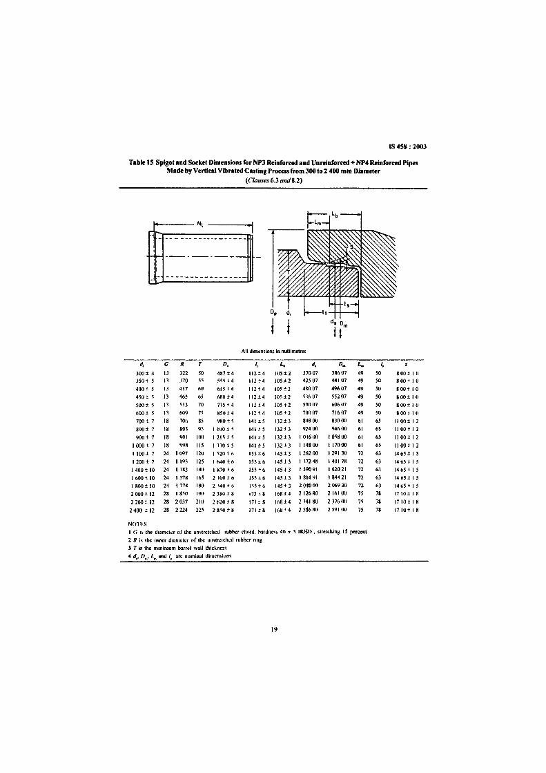
Table IS Spigotand SocketDimensions for NP3Reinforced and Unrelnforced+ NP4Reinforced PipesMade byVerticalVibratedCastingProcessfrom300to 2 400 mmDiameter
(C1au.,es6.3 and8.2)
t-----Nt
---. __._---
00 d,
! ! d. 0
t(All dimensions in miltimctres
d, G R T D. I, L. d, D. L. I,
300± 4 13 322 50 487±4 11214 105±2 37007 38607 49 50 8001 I 0350 j 5 13 .170 5~ 5~~ , 4 11214 IOS±2 42507 44107 49 50 800± I 0
400 t 5 13 417 60 61514 112 t4 105±2 48007 49607 49 50 800110
450 t ~ 13 465 65 6811 14 112±.4 105±2 ~1607 55207 49 50 800110
500± 5 n ~13 70 TIS' 4 11214 lOS! 2 59007 60607 49 SO 800±10
600 i 5 13 609 75 851114 11214 105±2 70007 71607 49 50 800 J 10
700 I 7 18 70(, 85 9801 ~ 14115 132±3 80800 8.1000 61 65 II OO± I 2
800± 7 18 803 95 I IUO j ~ 141 j 5 132 j 3 924 (10 94600 61 65 II OO±I 2
900± 7 18 901 100 121HS 141± 5 132±3 103600 I 0~8 00 61 65 II oo e : 2
100017 18 998 115 I H01 5 141± 5 132 ±3 I 14800 I 17000 61 65 1I00tl2
I 100± 7 24 , 097 120 I ~20 16 15516 145±3 126200 129130 72 63 1465 ± I 5
120017 24 1195 125 IM010 ISS1 6 14513 117248 140178 72 63 146S! I 5
1400110 24 , 183 140 1870 t 6 155±6 145±3 159091 162021 72 63 1465115
I bOO 1 10 24 1578 165 210016 155 i6 14513 181491 184421 72 63 1465.t I 5
1800110 24 1774 180 2 140 j (, 1'5i6 14513 2 04() 00 206930 72 63 1465± 15
2000i12 28 I 8~O 190 2380 ± 8 173 i a 168±4 212680 216100 75 78 1710118
2200±12 28 2037 210 2620 r 8 17118 168I4 214180 237600 7~ 78 1710 il 8
2400il2 28 2224 225 2 8~0 ± 8 171t8 168' 4 BS680 259100 75 78 1710± I 8
NOHSI G .. Ihe diameter of the unsiretchcd rubber chord. hardoes> 40 ;- ~ IRHD . stretching 15 percent
2 R iii Iht: Inner diameter of the unstretched rubber rmg
3 T is the mmimum barrel wall thickness
4 d•• 0... I,,, and I. arc nominal dimcn~iun"
19

IS 458: 2003
Table 16 Splaotand SocketDimensions for NP4Unrelnfon:edPipesMade byVibrated Castina Processfrom 300 to I SOO mm Diameter
(C/auses6.3 and8.2)
"I~--__ Nl
,,f- ---.-------I,o
00 d,
! ! d. 0
t(
AlldimenSIons ,n mllhmette'l
d, G R T D. I, t; d, D. L. I,
3OO~4 13 322 50 487±4 112~4 IOH2 37007 38607 49 50 800~IO
350~ 5 13 370 SS S5H4 IIh4 IOH2 42501 44107 49 50 800,010400,05 11 417 60 615,04 112~4 105<.2 48001 49607 49 50 800,010450~ 5 13 465 65 680H 112,04 IOH2 53607 55207 49 ~O 800,0 I (}500,0 5 13 513 10 73H4 IIh4 105H W007 60607 49 50 8oo~IO
600,05 13 609 15 850H 112H IOH2 70001 11607 49 50 800,010700~1 18 106 85 980,0 S 141,05 132,03 80800 83000 61 65 1100,012800,07 18 803 95 1100,05 141,05 13h3 92400 94600 61 65 1100,012900~7 18 901 100 121H5 141 ~ S 13h3 103600 105800 61 65 1I00~12
1000,01 18 998 lIS 1330,05 141 ±S 132*3 114800 111000 61 65 lloo~12
1100,01 24 1091 120 I 520H 15H6 1450,3 126200 129130 12 63 146H I 51200,01 24 I 195 125 1640%6 15H6 14H3 1312 48 140118 12 63 146S,oI~
1400 .. 10 24 1383 140 1870 .. 6 155.. 6 145.. 3 159091 162021 12 63 1465"151600,0 10 24 1518 165 2100*6 155*6 145*3 181491 184421 12 63 1465,0151800,0 10 24 1114 180 2300*6 ISS*6 145*3 204000 206930 12 63 1465,0 I 5
NOTESI G IS the diamelerof the unstretched rubberchord. hardness 40 ~ 5 lRHO. strelch,ns 15 percent:z R IS the Inner diameterof the un,tretched rubberrlnsJ T Is the minimum barrel wall th,ckness4 d••D•• L. ond I. are nominal dimensions
20

Tab
le17
Spig
otan
dSo
cket
Dim
ensi
ons
ofN
P3an
dN
P4C
lass
Pipe
sfr
om1
000
to2
600
mm
Dia
met
er(R
ubbe
rR
ing
Con
fine
dJo
int)
(Cla
uses
63
an
d8.
2)
RU
BB
ER
RIN
G

Tab
le17
(Con
clud
ed)
NO
TE
SI
Cor
eers
tobe
roun
ded
off.
2Th
edim
ensi
onsL
S.L
SP,1
$,T
.H.L
.ban
dKsh
allc
onfo
rmto
thev
alue
sgiv
enin
this
tabl
east
hese
arec
riti
cald
imen
sion
s.O
ther
dim
ensi
ons
aref
orgu
idan
ceon
ly.T
hefo
llow
ing
tole
ranc
essh
alla
pply
onth
ecri
tical
dim
ensi
ons.
(;j ... ~ ... s
.., ..,
D,m
enslt
;"u
LSa
ndL
SPT H
and
1SL b K
Tol
eran
ces
±7
mm
Sam
e:as
thaI
ofba
m:I
wal
lth
ickn
ess
give
nin
8.2
Hal
fth
eto
le..
..ce
onba
rrel
wal
lth
iclc
nc:s
sgiv
enin
8.1
±{l
.5m
m±
Im
mfo
r28
mm
and
±1.
5m
mfo
r3S
mm
±1.
75m
mfo
r20
nun
rubb
erri
ngch
ord
diam
eter
±l.
5m
mfo
r25
mm
rubb
erri
ngch
ord
diam
eter

Tab
le18
Spi
gota
ndSo
cket
Dim
ensi
ons
ofP2
Cla
ssPi
pes
(Rub
ber
Rin
gR
oll
onJo
int)
(Cla
uses
6.3
and
8.2)
N
RU
BB
ER
RIN
G« ~J
All
dim
ensi
onsin
mill
imct
res
'"Pi
peR
ubbe
rR
ing
Rub
ber
Rin
gT
TS
DS
0$
10
$1
DS
]R
LSD
KN
LT
HT
LS
PP
SH
XW
R.
....D
i.met
erC
kord
Inte
rnal
4IA
Dia
met
uD
iall
lde
r
(I)
(2)
(3)
(4)
m(6
)(7
)(8
)(9
)(1
0)(I
I)(1
2)(1
3)
(14)
(15)
(16)
(17)
(18)
(19)
(20)
(21)
(22)
80II
102
253
25
708
2834
35
56
595
8434
507
5.5
19
5I
I5.
510
0II
120
253
25
708
2834
35.
56
595
8434
507
55
19.5
II
5.5
150
II17
025
32.5
708
2834
35
56
595
8434
507
5.5
19.5
II
5.5
200
1123
030
3883
II38
345
6.5
6.5
113
9739
.550
75.
524
.5I
I5.
522
5II
255
3038
83II
3834
56.
56
511
397
39.5
507
5.5
24.5
1I
5.5
250
II27
530
3883
II38
345
6.5
6.5
113
9739
.5SO
75.
524
.5I
15.
530
012
340
4051
9012
4236
67
713
013
053
557.
56
341
I6
350
1240
045
5790
1242
366
77
135
145
5955
7.5
639
1I
640
012
450
5061
9012
4236
67
714
015
563
557.
56
441
I6
450
1250
050
6190
1242
366
77
140
155
6355
7.5
644
11
650
012
525
5567
9012
4236
67
714
517
069
557.
56
49I
I6
600
1664
065
7912
016
5648
810
9.5
185
185
8272
107.
557
.52
28
700
1674
070
8412
016
5648
810
9.5
190
195
8772
107.
562
.52
28
ril80
020
845
80%
150
2070
6010
1212
230
225
100
9012
.59
570
.52
210
... '"90
020
970
9010
815
020
7060
1012
1224
025
011
290
12.5
9.5
80.5
22
1000 ..
10
00
2110
6010
012
016
522
7766
II13
1326
526
512
499
1410
.58
95
22
II... ~

Tab
le18
(Con
clud
ed)
NO
TE
S
IC
om
ers
10be
rou
nd
edo
ff
1T
hedu
ncns
lOD
SO
Sl.
DS
3L
SP
TS
TIf
SJU
and
Ksh
allc
onfo
rmto
thev
alue
sgi
ven
Inth
ista
blea
sthe
sear
eCri
tical
dim
ensi
ons
Oth
erdi
men
sion
sare
forg
uida
nce
onI)
The
follo
win
gto
lera
nces
shal
lap
plyo
nth
ecnn
cald
lmen
sson
s
[I; ... Ul
QO ... §
.., ...
Dvn
enss
ons
Tan
dHT
TS
and
HO
Sl
OSJ
LSP
K&
S
Ch
ord
Dia
met
er
II 12 16 20 22
DS
l
±2
%2
±2
5±
3
±3
5
Tol
eran
ce..
Sam
eas
that
of
barr
el\..
allt
hick
ness
gJ..
en!D
8.2
Hal
fthe
tole
ranc
e:on
barr
elw
allt
hic
kn
ess
gree
nm
8.2
The
tole
ran
cem
mm
shal
lbe
asg
I...e
nbe
low
DS
3LS
PK
S
±3
±4
±1
25%
075
±3
±4
±I
25±
075
±3
5±
5±
200
±1
25
±4
±5
5±
225
±1
50
±4
5±
6±
275
±I
50

Tab
le19
Spi
got
and
Soc
ket
Dim
ensi
ons
ofP
3C
lass
Pipe
s(R
ub
ber
Rin
gR
oll
onJo
int)
(Cla
uses
6.3
and
8.2)
N
r:-I
--.......
........ x - - (/)
·~·"~I.
II-
LIE
FF
EC
TIV
EL
EN
GT
HI
All
dim
ensi
onsi
nm
illim
etre
s
NP
i.,.
Ru
bb
uR
ing
Rub
...r
Rin
gT
TS
OS
DS
lO
S1O
SJ
RlS
DK
NL
TH
TlS
PP
SH
XW
R,
v.
Dia
mtl
nC
'ord
In't
r•••
elf
Dia
met
erD
iam
eter
(I)
(2)
0)H
)(5
)(o
j(7
)(8
)(9
)(1
0)(1
0(1
21O
J)
(14)
(15)
(16)
(171
(l8J
(19
)(2
0)
(21
)(2
2)
80II
102
2532
.570
828
343
556.
595
8434
507
s519
.5I
I5.
5
100
II12
025
32.5
7U8
2834
35.
565
9584
3450
75.
519
.5I
I5.
5
150
II17
025
32.5
708
2834
35.
56.
595
8434
507
5.5
19.5
II
5.5
200
II23
035
4583
II38
345
5.5
6.5
120
115
46.5
507
5529
.5I
I5.
5
225
II25
535
4583
II38
345
5.5
6.5
120
115
46
550
75.
529
.5I
I5.
5
250
II27
535
4583
II38
345
5.5
6.5
120
115
46.5
507
552
95
II
5.5
300
1234
045
6090
1242
366
77
135
ISO
6255
7.5
639
I1
6
350
1240
055
7590
1242
366
77
145
190
7755
7.5
649
II
6
400
1245
0so
8090
1242
366
77
150
200
8255
7.5
654
II
6
450
1252
570
ss90
1242
360
77
160
240
9755
7.5
664
II
6
500
1257
075
100
9012
4236
67
710
525
010
255
75
669
II
6
600
1668
090
120
120
1656
488
109.
519
027
;12
372
1075
82.5
22
8r;;
700
1080
510
514
012
016
5648
810
9520
032
014
372
107.
59
75
22
8... !A ...
8(»'
20Q
1512
01<
>015
020
7000
1012
115
240
365
1MQ
U11
.5Q.
511
052
210
.. .... c c ...

Tab
le19
(Con
clud
ed)
NO
TE
S
IC
om
e"10
bero
unde
don
2T
heds
men
sron
sD
S]
DS
l[S
Pn
TH
SIf
fan
dA
shal
lcon
form
toth
e\al
ues
give
nIn
Ihl~
tabl
eas
thes
eare
cnn
cal
dim
ensr
ons
Oth
erdi
men
sion
sare
forg
uida
nce
cnlv
The
follo
wm
gto
lera
nces
shal
lapp
hon
the
cnnc
aldr
men
sron
,
Vi ... '"Cl
IO ... s to'
Dim
ensi
ons
Tan
dH
TT
San
dH
DS
2D
!>3
LSP
Ks.
S
Tot
eran
..es
Sam
eas
that
ofba
rrel
"all
thic
kn
ess
gJ.\
enm
8.2
Hal
fIhe
tole
ranc
eon
barr
el\\3
11th
ickn
ess
gnen
In8.
The
tole
ranc
eIJ
lm
msh
all
beas
gI'
enbe
low
..., '"
Ch
ord
Dia
met
erD
S}
DS
3L
SPK
11±
2",
3±
4±
I25
I~
",2
",3
±4
±1
:!5
16;1
:25
::t:
35±
5±
20
020
±3
",4
±5~
±2
25

IS 458: 2003
Table 20 Weight ofSpirals (Hard Drawn Steel) in Socket ofRlR Joint RCC Pipesof Different Classes (kg/Number)
(Clause 6.3)
In.rro •• Oi.mrttr NPl CI... NPl CI••• NP4 CI... PI CI... Pl CI... I'ln...or Pip••
ml11
(I) (2) (3) (4) (5) (6) (71SO O.OS O.OS O.OS O.OS O.OS O.OS
100 0.09 0.09 009 0.D9 0.09 OOl)150 0.12 0.12 0.12 012 0.12 o 15200 014 0.14 0.21 0.14 021 035225 0.15 IUS 0.26 0.15 0.26 1143250 0.\6 0.16 0.31 O.ln 0.31 0.51300 045 045 053 0.45 0.53 084350 (1.51 0.64 0.64 0.51 0.74 I 24400 OSb 071 071 0.56 O.QQ 16h
450 0.63 076 0.76 0.63 1.23 226500 O.(,S 0.87 1.08 0.68 1.57 28<600 0.81 1.00 212 1.52 2.88 474700 0'12 2.1(, 3.112 \.79 3.96 679SOO 1.14 2.87 4.67 2.04 6.2S '1l)lJ
900 1.50 4.06 603 2.63 S291000 191 3.33 1.29I 100 2",4 4.0SI 2(1(1 2.80 4.901400 J 811600 5.04I ROO 7252000 11.782200 12.88
NOTES
1 Longitudinal reinforcement 'ihall he propcrfiunul to the length of socket cage as given in Tubles 2 to JL
2 If mild ~tc(1 is used lor spiral reinforcement. the weight specified above shall be increased to 140/125.
9. \.2 The pipes shall be free from defects resultingfrom imperfect grading of the aggregate, mixing ormoulding.
9.1.3 Pipcs shall be free from local dents or bulgesgreater than 3.0 mm in depth and extending over alength in any direction greater than twice the barrelwall thickness.
9. \.4 Pipes may be repaired, if necessary, because ofaccidental injury during manufacture or handling andshall be accepted if in the opinion of the purchaser,the repairs are sound and appropriately finished andcured, and the repaired pipe conforms to therequirements of this specification.
9.2 Deviation from Straight
The deviation from straight in any pipe throughout itseffective length. tested by means of a rigid straightedge as described in IS 3597 shall not exceed, for alldiameters, 3 mm for every metre run.
10 TESTS
10.1 Test Specimens
All pipes for testing purposes shall be selected atrandom from the stock of the manufacturer and shall
27
be such as would not otherwise be rejected under thisstandard.
10.1.1 During manufacture, tests on compressivestrength of concrete cubes shall be done as describedin IS 516. For pressure pipes, splitting tensile strengthtests of concrete cylinders shall be carried out asdescribed in IS 5816. The manufacturer shall supply,when requ ired to do so by the purchaser or hisrepresentative, the results of compressive tests ofconcrete cubes (see 5.5.1) and split tensile tests ofconcrete cylinder (see 5.5.2) made from the concreteused for the pipes. The manufacturer shall supplycylinders or cubes for test purposes required by thepurchaser, and such cylinders or cubes shall withstandthe tests prescribed in 5,5.1 and 5.5.2. Every pressurepipe shall be tested by the manufacturer for thehydrostatic test pressure (fee 4.1). For non-pressurepipes, 2 percent of the pipes shall be tested forhydrostatic test pressure.
10.2 The specimens of pipes selected in accordancewith 10.1 shall be subjected to the following tests inaccordance with IS 3597:
a) Hydrostatic test,

IS4S8: 1003
Table 11 Design Requirements of Reinforced Conerete Collar for Pipes of Class NP1(Clauses 6 3 and 8.1)
Nomlo_lloloro_1 CoIl_r Dlmooolooo Rolofon:omoohPlamolor ......ofPipr Minimum Minimum Minimum'" Longitudmal, MildSteel or Spiral. Hard'"
( aulkmg Space Ihickness Length liard Drawn Steel Drawn Steel
rMlnlmum Welghi'number
onm nun mm mm kg/collar kg/collar(I) (2) (3) (4) (5) (6) (7)80 13 2S ISO 6 oOS 007
100 13 2S ISO 6 oOS OOSI~O 13 2S ISO 6 OOS 010200 13 25 ISO 6 oOS 01212S 13 2S ISO 6 oOS 0142~O 13 25 ISO 6 OOS 016300 16 30 ISO S 011 0221~{1 16 12 ISO S 011 02S400 16 32 ISO 8 011 0274~0 19 15 200 8 015 040~OO 19 15 200 8 o IS 060600 19 40 200 8 o 15 07070(1 19 40 200 8 023 I O~
800 19 4~ 200 S oZ3 ISS90(1 19 ~O ZOO 8 023 2 O~
1000 19 5S 200 8 033 Z2~
111I0 19 60 200 8 (J33 3091 20(1 19 65 ZOO 8 033 41114(1(J 19 7S ZOO 12 oSO 50816UO 19 SO ZOU IZor8+S 067 6 5~
I SOO 19 90 ZOO 120rS+8 U67 900Z eXIU 19 11I0 200 12 + 12 100 IZ IS220U 19 110 ZOO IZ + IZ 100 13 30
NOli \
I It rmtd stect rs uvcdtor vptral remtorccment. (he weight specified under (,,01 7 shall he increasedby a factor 140/125
1:sou grade mild steel wire may be used 8!lo remtorcernent tor collars 01 plpC!lo ot nommal mternal diameter up to 250 mm only. bymcreasmgtheweight b) d tac..lor 140/84 Whcrt~ onlyson grademildsteelwireIS w~ed lor ma"-mg collarcages.theweight01remtorcement...hall be total weight of col6 and 7 multiplied hy 140/84 I hi~ 11;allowedd' d process requirementJ internal diameter 01 ...ollar to !tUII the actual diameter ot pipes with muumum caullmg. space as given In col 2
b) Three-edge bearing test. andc) Permeability test,
10.1.1 The permeability test when conducted inaccordance with the method described in IS3597shallmeetthe requirementof final permeability,whichshallnot exceed 0.3 cm'.
NOIl - It I!l.recommended that uunal absorpuon should notexceed 2 0 em; and the duterence111 an)' two readings duringmitral ah,orpllOn should 110t be morc than 0 K ern'
II SAMPLING AND INSPECTION
11.1 Seale of Sampling
I \.1.1 LOI
In any consignment, all the pipes of same class. samesize and belonging to the same mix of concrete shallbe grouped together to constitute a lot.
11.1.2 For ascertaining the conformity of the material
28
to the requirementsofthis specification,samples"hallbe tested from each lot separately.
I \.\.3 The numberof pipesto be selected from the lotshalldependon thesizeof the lotandshallbeaccordingto Table 22.
11.1.3.1 These pipes shall be selected at random. Inorder to ensurethe randomness ofselecnon,proceduresgiven in IS 4905 may be followed.
11.2 Number of Tests and Criteria for Conformity
11.2.1 AIIthe pipes selectedaccording to 11.1.3 shallbe inspected for dimensional requirements (.ee 8),flmsh (see 9.1) and deviation from straight (see 9.1).A pipe failing to satisfy one or more of thesercquirementsshall be considered as defective.
11.2.\.1 The lot shall be declared as confonnmg tothese requirements if the number of defectives found

Table 22 Scale of Sampling and PermissibleNumber of Defectives
(Clauses I1.1J, 11.2.1.1 and 11.2.2)
IS 458: 2003
I \.2.2.1 The lot shall be declared as conforming tothe requirements of this specification if there is nofailure under 1\.2.2.
Sample PermissibleSize Numberof
Defectives(I) (2) (3) (4)
Up 10 50 8 0 25110100 13 I 310110300 20 2 530110500 32 3 750I andabove 50 5 10
in the sample does not exceed the number ofdefectivesgiven in col 3 of Table 22.
11.2.2 The lot having found satisfactory shall befurther subjected to the tests given under 10.2 exceptultimate load test. For this purpose, the number ofpipegiven in col 4 of Table 22 shall be selected from thelot. These pipes shall be selected from those that havesatisfied the requirements given in 11.2.1. For ultimateload test, the number of pipes to be checked shall beaccording to mutual agreement between the purchaserand the manufacturer. However, ultimate load test shallnot bedone for a lot size of 20 pipes or less.
No. of Pip••In the Lol
For Rfquiremtntlind er
CIRun"8 and 9
Simple. Size forTnt Under ('IIUlt
10.2 (Entudingllilimal. Load
T••l)
12 MARKING
12.1 The following information shall be clearly markedon each pipe:
a) Indication of the source of manufacture.
b) Class and size of pipe.
c) The words 'SPUN PIPE' or 'VIBRATEDCAST PIPE (UNREIN FORCED)' or'VIBRATED CAST PIPE (REINFORCED)'as may be applicable, and
d) Date of manufacture.
The above information shall be clearly marked onoutside only for pipes up to and including 350 mminternal diameter, and both outside and inside for pipesabove 350 mm internal diameter.
12.1.1 Each pipe may also be marked with the StandardMark.
12.1. t.l Tbe use of the Standard Mark is governed bythe provisions of the Bureau of Indian Standard Act.1986 and the Rules and Regulations made thereunderThe details of conditions under which the licence forthe use of the Standard Mark may be obtained fromthe Bureau of Indian Standards.
ANNEXA
(Clause 2)
LIST OF REFERRED INDIAN STANDARDS
IS No.
269: 1989
383: 1970
432
.{Part I): 1982
(Part 2): 1982
455: 1989
Title
Specification for 33 grade ordinaryPortland cement (fourth revision)Specification For coarse and fineaggregates from natural sources forconcrete (second revision)Specification for mild steel andmedium tensile steel bars and harddrawn steel wires for concretereinforcementMild steel and medium tensile steelbars (third revisionsHard-drawn steel wire (thirdrevision)Specification For Portland slagcement (fourth revision)
29
IS No.
456: 2000
516: 1959
1489
(Part I): 1991(Part 2) : 1991
1566: 1982
1785
(Part I): 1983
Title
Plain and reinforced concreteCode of practice (fourth revision)Method of test for strength ofconcreteSpecification for Portland pozzolanacementFly ash based (third revision)Calcined clay based (third revision)Specification for hard-drawn steetwire fabric for concrete reinforcement (second revision)Specification for plain hard-drawnsteel wire for prestressed concreteCold drawn stress relieved wire(second revision)

IS 458: 2003
IS No. Title ISNo. Title
(Part2) : 1983 As drawn wire (first revision) 5816: 1999 Splitting tensile strength of concrete
1786: 1985 Specification for high strength - Method of test (first revision)
deformed steel bars and wires for 7322: 1985 Specification for specials for stee I
concrete reinforcement (third cylinder reinforced concrete pipes
revision) (first revision)
2062: 1999 Steel for general structural purposes IlO4I : 1990 Specification for rapid hardening
- Specification (fifth revision) Portland cement (second revision)
3597: 1998 Methods of test for concrete pipes ll()43: 1991 Specification for hydrophobic
(second revision)Portland cement (second revision)
3812: 1981 Specification for fly ash for use as8112: 1989 Specification for 43 grade ordinary
pozzolana and admixture (firstPortland cement (first revision)
revision)9103: 1999 Concrete admixtures - Specifica-
4905: 1968 Methods for random samplingtion (first revision)
5382: 1985 Specification for rubber sealing rings12269: 1987 Specification for 53 grade ordinary
Portland cementfor gas mains, water mains and sewers 12330: 1988 Specification for sulphate resisting(first revision) Portland cement
30

Bureau 01Indian Standards .
BIS is a statutory institution established under the Bureau of Indian Standards Act. 1986 to promoteharmonious developmentof the activities of standardization, marking and quality certification of goodsandattending toconnected mailers in thecountry.
Copyright
BIS has the copyrightof all its publications. No part of these publications may be reproduced in any formwithout the prior permission in writing of BIS. This does not preclude the free use. in the course ofimplementing the standard, of necessary details, such as symbols and sizes, type or grade designations.Enquiries relating to copyright be addressed to theDirector (Publications), BIS.
Review 01Indian Standards
Amendments are issued to standards as the needariseson the basisof comments. Standards are alsoreviewedperiodically; a standard along withamendments is reaffirmed whensuchreview indicates that no changes areneeded; if the review indicates that changes are needed. it is taken up for revision. Usersof Indian Standardsshould ascertain thattheyare in possession of the latestamendments or editionby referring to the latestissueof'BISCatalogue' and 'Standards: Monthly Additions'.
ThisIndianStandard hasbeendeveloped from Doc : No. CEDS3 (6006).
AmendmentsIssuedSince Publication
Amend No. Dateof Issue
BUREAU OFINDIAN STANDARDS
TextAffected
Headquarters :
Manak Dhavan, 9 BahadurShahZafarMarg. NewDelhi 110002Telephones: 23230131,23233375.23239402
Telegrams : Manaksanstha(Common to alloffices)
Regional Offices;
Central ManakBhavan, 9 BahadurShahZafarMargNEWDELHI110002
C.l.T.Campus. IVCrossRoad,CHENNAI600 113
1/14C.l.T.Scheme VIIM.V. I. P.Road, KankurgachiKOLKATA 700054
SCO335-336, Sector34-A,CHANDIOARH 160022
Eastern
Northern
Southern
Western
Branches
Telephone
{2323 761723233841
{23378499,2337856123378626,23379120
{260 38432609285
{2254 1216.2254144222542519,22542315
ManakaJaya, E9 MIDC, Marol.Andheri (East) {2832 9295.28327858MUMBAI400093 28327891,28327892
AHMEDABAD. BANOALORE. BHOPAL. BHUBANESHWAR. COIMBATORE. FARlDABAD.OHAZIABAD. OUWAHATI. HYDERABAD. lAIPUR. KANPUR. LUCKNOW. NAOPUR.PARWANOO. PATNA. PUNE. RAIKOT. THIRUVANANTHAPURAM. VISAKHAPATNAM.