is 3121 (1981): rigging screws and stretching screws · 5.2 stretching screws of the double-ended...
TRANSCRIPT

Disclosure to Promote the Right To Information
Whereas the Parliament of India has set out to provide a practical regime of right to information for citizens to secure access to information under the control of public authorities, in order to promote transparency and accountability in the working of every public authority, and whereas the attached publication of the Bureau of Indian Standards is of particular interest to the public, particularly disadvantaged communities and those engaged in the pursuit of education and knowledge, the attached public safety standard is made available to promote the timely dissemination of this information in an accurate manner to the public.
इंटरनेट मानक
“!ान $ एक न' भारत का +नम-ण”Satyanarayan Gangaram Pitroda
“Invent a New India Using Knowledge”
“प0रा1 को छोड न' 5 तरफ”Jawaharlal Nehru
“Step Out From the Old to the New”
“जान1 का अ+धकार, जी1 का अ+धकार”Mazdoor Kisan Shakti Sangathan
“The Right to Information, The Right to Live”
“!ान एक ऐसा खजाना > जो कभी च0राया नहB जा सकता है”Bhartṛhari—Nītiśatakam
“Knowledge is such a treasure which cannot be stolen”
“Invent a New India Using Knowledge”
है”ह”ह
IS 3121 (1981): Rigging Screws and Stretching Screws [MED10: Mechanical Engineering]


AMENDMENT NO. 1 FEBRUARY 1986
TO
I S : 3 1 2 1 - 1 9 8 1 SPECIFICATION FOR RIGGING SCREWS AND STRETCHING SCREWS
(First Revision)
(Page 2, clause 6.4) - S u b s t i t u t e t h e fo l lowing for t h e e x i s t i n g c l a u s e :
'6.4 Galvanizing - Unless o therwise s p e c i f i e d , all components of t h e assembled s t r e t c h i n g screw and r i g g i n g screw s h a l l be ga lvanized as per I S : 14759-1979 'Hot -d ip z inc c o a t i n g s on s t r u c t u r a l s t e e l and o t h e r a l l i e d p roduc t s ( f i r s t revision)'. The t o l e r a n c e s s p e c i f i e d i n 3.3 s h a l l apply a f t e r g a l v a n i z i n g . A l l screw t h r e a d s s h a l l be 'brush ' or 'spun' ga lvan i zed . The purchaser s h a l l s t a t e c l e a r l y a t t h e t ime o f t h e enqu i ry and o rder whether he r e q u i r e s t h e z inc coa t ing to be t e s t e d , and t h e number of samples to be t e s t e d .
Note - I t is recommended t h a t not more than one sample of each s i z e of r i g g i n g screws per consignment should normal ly b e sub jec t ed t o t h i s t e s t . '
(EDC 32)
Reprography U n i t , I S I , New D e l h i , I n d i a

(Reaffirmed 2012)
SPECIFICATION FOR RIGGING SCREWS AND STRETCHING SCREWS
( First Revision )
1. Scope - Specifies materials, components, dimensions, finishing and tests for rigging screws and stretching screws (double-ended and single-ended), of the following nominal sizes:
a) Rigging screws: M12 to M90, and b) Stretching screws: M6 to M52.
2. Terminology — For the purpose of this standard, the following definitions shall apply. 2.1 Rigging Screw — A tubufar body threaded internally at each end in opposite hand and into which end fittings of optional form (for example, elongated eye, stud eye, screwed fork jaw) having screwed shanks are fitted.
2.2 Stretching Screw — An open body consisting of two reins connecting a box at each end, with a central hole threaded In opposite hand, into which fittings of optional form (for example, stud eye, elongated eye, screwed fork jaw ) having screwed shanks are fitted. 2.3 Single-Ended Stretching Screw — An open body with a swivel fitted at one end and screwed internally at the other.
2.4 Double-Ended Stretching Screw — An open body, the solid ends of which are Internally screwed, one right-hand and the other left-hand.
3. Shape and Dimensions
3.1 Rigging Screws
3.1.1 The shapes and dimensions of rigging screws, tubular body screwed eye, screwed fork and screwed stud eye shall be as shown in Tables 1, 2, 3, 4 and 5 respectively.
3.1.2 The dimensions oft he bolts and nuts shall comply with the requirements specified in IS : 1363-1967 'Specification for black hexagonal bolts, nuts and lock nuts (dia 6 to 39 mm ) and black hexagonal screws (dia 6 to 24 mm ) ( first revision )' in respect of sizes from 6 to 39 mm and with those specified in IS : 3133-1966 'Specification for hexagonal bolts and nuts ( M42 to M150 )' in respect of sizes beyond 39 mm. The bolt heads and nuts shall be of lock-nut thickness for sizes up to 39 mm. The bolts and nuts shall be fitted with a split cotter pin conforming to IS : 549-1974 'Specification for split pins (second revision)' positioned outside the nut. 3.2 Stretching Screws
3.2.1 The shapes and dimensions of open body, screw byes and swivel eyes shall be as shown in Table 6.
3.2.1.1 The dimensions given in Table 6 for the cross-section of the sides of the body are such that the combined cross-sectional area is about twice the area at the bottom of the thread of the screw eye shank. 3.3 Tolerances
3.3.1 The permissible variation from any of the dimensions given in Tables 1 to 6 shall not exceed ± 5 percent, except that steel tube used for tubular body shall have the tolerances as specified in IS : 1161-1979 'Specification for steel tubes for structural purposes (third revision )'.
3.3.2 The screw threads on the eye and fork ends in the tubular body and on the screw eyes shall (after galvanizing for screw eyes and other parts when so specified) conform to the coarse tolerance class specified in IS : 4218 (Part IV) -1976 'ISO metric screw threads : Part IV Toleranc-ing system' (Issued in six parts).
Adopted 26 November 1981 © September 1982, ISI Gr 5
INDIAN STANDARDS INSTITUTION MANAK BHAVAN, 9 BAHADUR SHAH ZAFAR MARG
NEW DELHI 110002
Indian Standard
Wir
e R
opes
and
Wir
e P
rodu
cts
Sec
tiona
l C
omm
ittee
, ED
C 3
2; S
teel
Wir
e R
opes
Sub
com
mitt
ee, E
DC
32
:2 [
Ref
: Doc
: ED
C 3
2 (
3215
])
UDC 621.382.2 IS : 3121 - 1981

IS : 3121 - 1981
4. Material 4.1 Rigging Screws
4.1.1 Tubular body — The tubular body shall be made from hot-finished steel tubing having a minimum tensile strength of 345 N/mm2.
4.1.1.1 Alternatively, the tubes may be either cold-drawn seamless, or electric resistance welded, having a minimum tensile strength of 315 N/mm2.
4.1.2 For tubular bodies, if machined from the solid, material shall conform to Designation C20 of IS : 1570-1961 'Schedules for wrought steels for general engineering purposes' .
4.1.3 Screwed eye, screwed fork and screwed stud eye — The screwed eye, screwed fork and screwed stud eye shall be weldless, and their material shall conform to Designation C20 of I S : 1570-1961. 4.2 Stretching Screw
4.2.1 The body, the screw eyes and swivel eyes shall be weldless, and shall be made of steel conforming to Designation C20 of IS : 1570-1961.
4.2.2 The screwed collar nut for the swivel eye may be made from hot-finished seamless steel tube. 4.3 Bolts and Nuts — Bolts and nuts fitted to secure the thimble in the fork shall be made from open-hearth steel complying with the requirements of either IS : 226 - 1975 'Specification for structural steel ( standard quality ) ( fifth revision )' or conforming to Designation C20 of IS : 1570-1961. In either case, the steel shall have a minimum tensile strength of 440 N/mm2 and a maximum strength of 520 N/mm2. 5. Construction 5.1 Rigging screws shall consist of a tubular body, with both ends screwed internally for the screwed shanks of the end fittings, one end being threaded right-hand and the other left-hand.
5.1.1 The assembly of the rigging screw ( see Table 1 ) shall be either of the following: a) A tubular body (see Table 2) fitted at each end with an elongated screw eye (see Table 3); or b) A tubular body, fitted at one end with an elongated screw eye, including a shackle with a
bolt, nut and split cotter pin; and at the other end with a fork (see Table 4), including a solid wire rope thimble secured by means of a bolt, nut and split cotter pin or a wire rope socket with a screwed stud eye ( see Table 5 ).
5.2 Stretching screws of the double-ended type shall consist of a central open body provided with an indentical short screw eye at each end, one screw eye being threaded right-hand and the other left-hand, as shown in the figure in Table 6. Stretching screws of the single-ended type shall consist of a central open body provided with a swivel eye at one end and a long right-hand screw at the other end, as shown in the figure in Table 6. 6. General Requirements 6.1 Thimbles used shall comply with the requirements for solid thimbles specified in IS : 2315-1978 'Specification for thimbles for wire ropes (first revision)' and sockets with IS : 2485-1979 'Specification for drop forged sockets for wire ropes for general engineering purposes (first revision)'. 6.2 Shackles shall be in accordance with IS : 6132-1971 'Specification for shackles' except that the heads and nuts shall be of lock-nut thickness, and the split cotter pin shall be positioned outside the lock-nut. 6.3 Heat Treatment — Tubular bodies, screw forks, screw stud eyes, screw eyes and swivel eyes shall be normalized after completion of all forging operations and before machining. A suitable normalizing treatment is to uniformly heat them in a furnace until the whole of the metal has attained a temperature between 880°C and 910°C. They are then withdrawn from the furnace and allowed to cool in still air. 6.4 Galvanizing — Unless specified, otherwise, all components of the assembled stretching screw and rigging screw shall be supplied galvanized. The galvanizing shall be carried out by the 'hot process' and shall consist of a continuous coating of zinc of a puritv not less than 985 percent The tolerances specified in 3.3 shall apply after galvanizing. All screw threads shall be 'b rush ' or ' s p u n ' galvanized. The purchaser shall state clearly at the time of the enquiry and order whether he requires the zinc coating to be tested, and the number of samples to be tested.
Note — It is recommended that not more than one sample of each size of rigging screw per consignment should normally be subjected to this test.
2

IS : 3121 - 1981
6.5 Workmanship 6.5.1 Rigging screw
6.5.1.1 Body — The tubular body shall be neatly and cleanly made and finished. The ends of the body shall be swaged hot externally to cylindrical form to permit a screw thread of full depth when tapping. When made from the thinnest tube listed in Table 2, the ends of the body shall be 'up-set' by a forging operation to increase thickness of the tubing to the required value so that the value of dimension F (see Table 2) is maintained after swaging down. Alternatively, the body may be machined from solid bar.
6.5.1.2 Screwed eye, screwed fork and screwed stud eye — The screwed eye, screwed fork and screwed stud eye shall be cleanly forged and finished; all fins or flashes produced in forging shall be dressed to a level surface. The length of the thread on the fork and eye shanks shall be such that the ends meet at the centre of the body when they are screwed home.
6.5.1.3 Fork and thimble — The thimble, when in place in the fork, shall be capable of free movement.
6.5.2 Stretching screw 6.5.2.1 Body — The body shall be a solid forging without weld, neatly and cleanly made and
finished. Flashes or fins produced in manufacture shall be dressed to a level surface. The faces of each boss of the body shall be machined.
6.5.2.2 Screw eye — The screw eye shall be a solid forging without weld, neatly made and finished. Flashes or fins produced in manufacture shall be dressed to a level surface. The length of the thread on the screwed shanks shall be such that the shank ends of the screw eyes, or screw eye and swivel, shall meet when screwed home.
6.5.2.3 Swivel eye — The swivel eye (see Table 6) shall be solid forging without weld neatly and cleanly made and finished Flashes or fins produced in manufacture shall be dressed to a level surface. The shanks shall be machined and screwed (fine thread ) and be provided with a tubular nut. The shoulder ( dimension F ) shall be machine-faced. The end of the screw shanks shall be riveted over the collar nut to form an effective head. The swivel eye shall swivel freely after assembly. 6.6 Each component of the completed rigging screw or stretching screw shall be free from any visible flaw or defect. 6.7 Certificate of Test — The manufacturer shall supply a certificate of test with every delivery of rigging screw or stretching screw in the form given in Appendix A. 7. Tests 7.1 Proof Testing— Each completed rigging screw or stretching screw shall be subjected to the appropriate proof load given in Table 1 or Table 6 which it shall withstand without any sign of defect. 7.2 Tests for Galvanizing — When specified otherwise by the purchaser, samples of each component of the completed rigging screw, including screw threads, shall be tested in accordance with IS : 2633-1972 'Methods of testing uniformity of coating on fine coated articles (first revision )' and IS : 6745-1972 ' Methods for determination of weight of zinc coating on zinc coated iron and steel articles'. 8. Enquiry and Order 8.1 This standard provides for alternative designs and the enquiry and order should state the type of screw required by reference to the figures. When an assembly different from that shown in the figures is called for, or when lock-nuts are required, it is incumbent upon the purchaser to give full details of such special requirements. 8.2 The rigging screws shall be supplied in galvanized condition in case nothing is stated in the enquiry and order about the surface coating of the rigging screws. 8.3 When lock-nuts are required, or if the stretching screws are required ungalvanized, this should be clearly stated in the enquiry and order. 9. Marking 9.1 Each rigging screw and stretching screw shall be permanently and legibly stamped with the safe working load given in Tables 1 and 6, and also with such marks and symbols as will allow identi-fication with the manufacturer's Certificate of Test (see Appendix A ). Care shall be taken that the stamps used have a concave surface where applicable and that the indentation is neither too sharp nor excessive in depth.
9.1.1 ISI Certification Marking — Details available with the Indian Standard Institution.
3

IS : 3121 - 1981
TABLE 1 DIMENSIONS FOR RIGGING SCREWS ( Clauses 3.1.1, 3.3.1, 5.1.1, 7.1 and 9.1 )
Assembly with Screwed Eyes at Both Ends
Assembly with Screwed Eye and Shackle at One End; Screwed Fork and Thimble at Other End
Assembly with Screwed Eye and Shackle at One End; Screwed Eye and Wire Rope Socket at Other End
Nominal S i z e
A
M12 M16 M20 M24 M27 M30 M33 M36
M39
M45
M52 M56 M60 M64 M68 M75
M80 M90
Dia of Rope
mm
8 10 12 14
16 18 20 22
25
29 32 35 38 41 44 48
51 54
Nominal Diaof
Bolt & Nut G
mm
M12 M14 M16
M20 M22 M27
M30 M30
M33
M39 M45 M52 M52
M58 M64 M70 M76
M85
H1
Closed Open mm
330 370 400
475 550 550
600
600
660
700
750 775 800
1 070 1 120 1 270
1 360
1 440
mm
525 550 570 700 825 825
875
875
960
960
1 000 1 025 1 050
1 450 1 590 1 700
1 760
1 860
H2
Closed Open
mm
330 370 400
475 550 550 600 610
660
700
750 760 780
1 050 1 100 1 240
1 330 1 400
mm
525 550 570
700 825 825
875
875
960
960
1 000 1000 1 025
1 420 1 500 1 660
1 730 1 820
Proof Load
kN
10.0 18.0 28.0
36.0 44.0 63.0
75.0
86.0
100.0
112.0
144.0
194.0 214.0
286.0 342.0 400.0
500.0
624.0
Safe Working
Load
kN
5.0 9.0
14.0
18.0 22.0 31.5
37.5
43.0
50.0
56.0
72.0 97.0
107.0
143.0 171.0 200.0
250.0
312.0
4
IS : 3121 - 1981
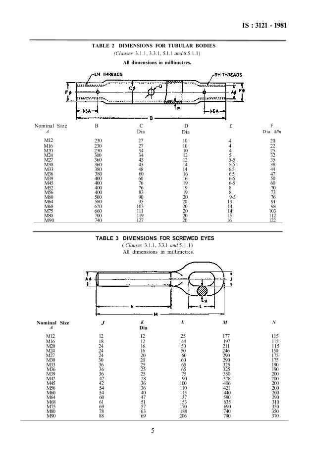
TABLE 2 DIMENSIONS FOR TUBULAR BODIES (Clauses 3.1.1, 3.3.1, 5.1.1 and 6.5.1.1)
All dimensions in millimetres.
( Clauses 3.1.1, 3.3.1 and 5.1.1) All dimensions in millimetres.
Nominal Size A
M12 M16 M20 M24 M27 M30 M33 M36 M39 M42 M45 M56 M60 M64 M68 M75 M80 M90
J
12 18 24 24 24 30 36 36 36 42 42 54 54 60 61 69 78 88
K Dia 12 12 16 16 20 20 25 25 25 28 36 36 40 47 51 57 63 69
L
25 44 50 50 60 60 65 65 75 90
100 110 115 137 153 170 188 206
M
177 197 211 246 290 290 325 325 350 378 406 421 440 580 635 690 740 790
N
115 115 115 150 175 175 190 190 200 200 200 200 200 290 310 330 350 370
5
Nominal Size A
M12 M16 M20 M24 M27 M30 M33 M36 M39 M45 M52 M56 M60 M64 M68 M75 M80 M90
B
230 230 230 300 360 360 380 380 400 400 400 400 500 580 620 660 700 740
C Dia
27 27 34 34 43 43 48 60 60 76 76 83 90 95
103 111 119 127
D Dia
10 10 10 12 12 14 14 16 16 19 19 19 20 20 20 20 20 20
£
4 4 4 5 5-5 5-5 65 65 6-5 6-5 8 8 9-5
13 14 14 15 16
F Dia Mln
20 22 25 32 35 38 44 47 50 60 70 73 76 91 98
103 112 122
TABLE 3 DIMENSIONS FOR SCREWED EYES
IS : 3121 - 1981
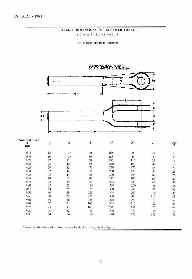
TABLE 4 DIMENSIONS FOR SCREWED FORKS ( Clauses 3.1.1, 3.3.1 and 5.1.1)
All dimensions in millimetres.
*Permissible alternative form shown by dash-dot line in the figure.
6
Nominal Size A
Dia
M12 M16 M20 M24 M27 M30 M33 M36 M39 M45 M52 M56 M60 M64 M68 M75 M80 M90
J
12 19 22 25 29 32 35 39 42 52 54 60 70 60 67 73 79 84
K
9.5 9.5
12 12 12 14 14 16 19 22 25 29 29 26 28 30 32 34
L
30 50 60 65 70 75 85 90
100 115 125 125 135 135 145 160 175 190
M
165 185 195 240 270 280 300 315 335 350 370 375 380 508 553 596 640 684
N
115 115 115 150 175 175 190 190 200 200 200 200 200 290 310 330 350 370
P
29 32 35 42 48 54 60 60 66 80 95
100 110 127 142 157 175 193
Q*
12 12 16 19 22 25 25 29 32 38 45 48 52 52 56 64 72 76

IS : 3121 - 1981
TABLE 5 DIMENSIONS FOR SCREWED STUD EYES
( Clauses 3.1.1, 3.3.1 and 5.1.1 )
All dimensions in millimetres.
7
Nominal Size A
Dia
M12 M16 M20 M24 M27 M30 M33 M36 M39 M45 M52 M56 M60 M64 M68 M75 M80 N90
J
12 16 20 24 25 30 33 36 39 40 47 52 56 60 66 71 77 89
K
17 22 25 25 25 36 36 40 40 50 57 66 73 80 89 96
105 118
M
165 185 195 230 270 270 300 300 325 350 370 385 400 533 584 633 677 721
N
115 115 115 150 175 175 190 190 200 200 200 200 200 289 310 330 350 370
P Dia
26 40 46 46 52 66 66 72 78 78 88
100 108 120 132 144 156 178
Pin Dia
12-5 19 22 22 25 32 32 35 38 38 43 49 52 58 64 70 76 87

TA
BL
E 6
DIM
EN
SIO
NS
FOR
ST
RE
TC
HIN
G S
CR
EW
S
(Cla
uses
3.2
.1,
3.2.
1.1,
3.3
.1,
5.2,
6.5
.2.3
, 7.
1 an
d 9.
1)
All
dim
ensi
ons
in m
illi
met
res.
Nom
inal
S
ize
A
M6
M8
M10
M
12
M14
M
16
M20
M
22
M24
M
30
M36
M
45
M52
Ass
emb
ly
and
Bod
y
B
C
D
E
F
L S
T
100
125
180
200
225
250
315
355
400
450
450
450
450
6 8 10
12
15
18
. 20
22
24
30
36
40
45
5 6 8 10
12
14
16
18
20
22
28
36
40
12
16
19
22
25
29
33
41
43
50
60
75
100
9 13
15
19
22
24
30
33
36
45
55
58
75
32
35
45
54
60
66
80
88
100
120
135
165
190
10
13
15
18
21
24
30
32
35
42
50
60
70
11
13
15
18
22
24
30
32
35
42
50
60
70
Scr
ew E
yes
and
Sw
ivel
E
yes
G
K
M
M1
M2
U
V
9 13
16
19
22
24
30
33
36
44
52
67
80
6 8 10
12
12
14
16
18
18
24
28
35
42
80
100
130
150
175
200
230
270
310
350
380
415
450
105
140
180
220
250
275
325
390
435
500
510
535
535
50
90
75
90
105
115
135
155
175
210
250
300
340
9 11
13
17
19
22
26
30
34
40
49
58
65
6 8 10
13
14
16
20
22
24
30
36
45
52
Pro
of
Saf
e W
orki
ng
Loa
d L
oad
kN
UN
2.0
1.0
3.0
1.5
6.0
3.0
9.0
4.5
12.0
6.
0 15
.2
7.6
22.4
11
.2
32.4
16
.2
40.0
20
.0
63.0
31
.5
90.0
45
.0
142
71
190
95
IS : 3121 - 1981
8

IS : 3121 - 1981
A P P E N D I X A ( Clauses 6.7 and 9.1 )
PRO FORMA FOR CERTIFICATE OF TEST
Its safe working load is kN.
Manufacturer.
Signature
Date
E X P L A N A T O R Y N O T E
This standard, originally published in 1965, has been revised to Introduce definitions of 'rigging screw' and 'stretching screw' and latest development in this field.
It is sometimes desirable to fit the threaded shanks of rigging screws and stretching screws with lock-nuts to prevent possible slacking back, for example, in the case of wire rope guys on derrick cranes. Where lock-nuts are required, this should be clearly specified in the enquiry or order.
The rigging screw assemblies specified are meant for normal conditions of use, but such assemblies may be varied, if desired, by fitting a fork at each end, or by fitting an ordinary thimble In place of solid thimble. It is incumbent upon the purchaser, however, to specify any such variations in the enquiry and order.
It is recommended that for normal conditions of service, the working load of the rigging screw or stretching screw should not exceed one-half the specified proof load. In all cases, however, where an assembly is made of various components, for example, screws, wire rope, shackles, etc, the safe working load of the assembly should be that of the weakest component in the assembly.
*Strike out what is not relevant.
Printed at New India Printing Press, Khurja, India
We hereby warrant that the supplied conform in all respects with
IS : 3121 -1981 and that each has been subjected to the proof load ( kN)
specified In Table of that standard, and was, after such test, duly examined by a competent person and found free from any visible defects.
9