is 1879 (2010): malleable cast iron pipe fittings ... · is 1879 : 2010 outside diameter of an...
TRANSCRIPT

Disclosure to Promote the Right To Information
Whereas the Parliament of India has set out to provide a practical regime of right to information for citizens to secure access to information under the control of public authorities, in order to promote transparency and accountability in the working of every public authority, and whereas the attached publication of the Bureau of Indian Standards is of particular interest to the public, particularly disadvantaged communities and those engaged in the pursuit of education and knowledge, the attached public safety standard is made available to promote the timely dissemination of this information in an accurate manner to the public.
इंटरनेट मानक
“!ान $ एक न' भारत का +नम-ण”Satyanarayan Gangaram Pitroda
“Invent a New India Using Knowledge”
“प0रा1 को छोड न' 5 तरफ”Jawaharlal Nehru
“Step Out From the Old to the New”
“जान1 का अ+धकार, जी1 का अ+धकार”Mazdoor Kisan Shakti Sangathan
“The Right to Information, The Right to Live”
“!ान एक ऐसा खजाना > जो कभी च0राया नहB जा सकता है”Bhartṛhari—Nītiśatakam
“Knowledge is such a treasure which cannot be stolen”
“Invent a New India Using Knowledge”
है”ह”ह
IS 1879 (2010): Malleable cast iron pipe fittings _Specification [MTD 6: Pig iron and Cast Iron]


© BIS 2010
B U R E A U O F I N D I A N S T A N D A R D SMANAK BHAVAN, 9 BAHADUR SHAH ZAFAR MARG
NEW DELHI 110002
March 2010 Price Group 10
IS 1879 : 2010
Hkkjrh; ekud
/kkro/;Z <yoka yksgk ikbi fQfVax — fof'kf"V( rhljk iqujh{k.k )
Indian Standard
MALLEABLE CAST IRON PIPE FITTINGS —SPECIFICATION
( Third Revision )
ICS 23.040.10; 23.040.40

Pig Iron and Cast Iron Sectional Committee, MTD 6
FOREWORD
This Indian Standard (Third Revision) was adopted by the Bureau of Indian Standards, after the draft finalized bythe Pig Iron and Cast Iron Sectional Committee had been approved by the Metallurgical Engineering DivisionCouncil.
This standard was first published in 1961 and subsequently revised in 1975 and 1987. While reviewing thestandard in the light of the experience gained during these years the Committee decided that the standard may befurther revised.
In this standard all amendments issued earlier have been incorporated.
For the purpose of deciding whether a particular requirement of this standard is complied with, the final value,observed or calculated, expressing the result of a test or analysis, shall be rounded off in accordance with IS 2 : 1960‘Rules for rounding off numerical values (revised)’. The number of significant places retained in the rounded offvalue should be the same as that of the specified value in this standard.
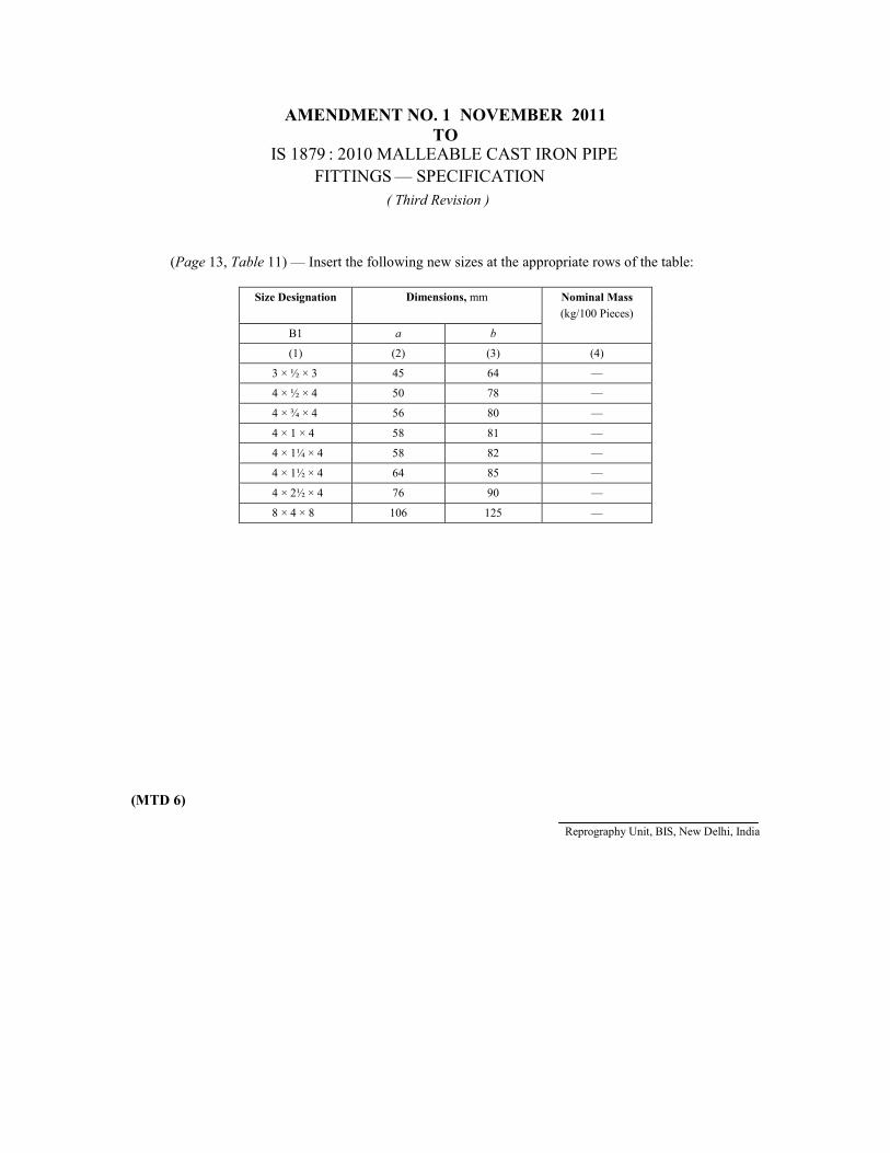
AMENDMENT NO. 1 NOVEMBER 2011TO
( Third Revision )
(Page 13, Table 11) — Insert the following new sizes at the appropriate rows of the table:
Size Designation Dimensions, mm Nominal Mass(kg/100 Pieces)
B1 a b
(1) (2) (3) (4)
3 × ½ × 3 45 64 —
4 × ½ × 4 50 78 —
4 × ¾ × 4 56 80 —
4 × 1 × 4 58 81 —
4 × 1¼ × 4 58 82 —
4 × 1½ × 4 64 85 —
4 × 2½ × 4 76 90 —
8 × 4 × 8 106 125 —
(MTD 6)
Reprography Unit, BIS, New Delhi, India
IS 1879 : 2010 MALLEABLE CAST IRON PIPEFITTINGS — SPECIFICATION

1
IS 1879 : 2010
1 SCOPE
1.1 This standard covers requirements for followingtypes of malleable cast iron pipe fittings threaded inaccordance with IS 554 for general purposes for thetransmission of fluid and gas up to the limit of pressureand temperature specified in 1.3. These are indicatedin following sections:
Section 1 GeneralSection 2 Elbows, including twin elbows,
union elbows and side outlet elbowsSection 3 Tees including pitcher tees and side
outlet teesSection 4 CrossesSection 5 Bends including long sweep bends
and return bendsSection 6 SocketsSection 7 Bushing and hexagon nipplesSection 8 BacknutsSection 9 Caps and plugs andSection 10 Unions
1.2 Dimensions which are not included in the standardare left to the discretion of the manufacturer dependingon the end use of the fittings.
1.3 These fittings shall be suitable for working pressureof up to 1.4 MPa in the case of water and up to 0.7 MPain the case of steam, air, gas and oil at a temperaturenot exceeding 100°C.
2 REFERENCES
The standards listed below contain provisions whichthrough reference in this text, constitute provisions ofthis standard. At the time of publication, the editionsindicated were valid. All standards are subject torevision and parties to agreements based on thisstandard are encouraged to investigate the possibilityof applying the most recent editions of the standardsindicated below:
IS No. Title
554 : 1999/ Pipe threads where pressure tightISO 7-1 : 1994 joints are made on the threads —
Dimensions, tolerances anddesignation (fourth revision)
Indian Standard
MALLEABLE CAST IRON PIPE FITTINGS —SPECIFICATION
( Third Revision )
IS No. Title
1387 : 1993 General requirements for the supplyof metallurgical materials (secondrevision)
4759 : 1996 Hot dip zinc coatings as structuralsteel and other allied products(third revision)
4905 : 1968 Methods for random sampling8999 : 2003/ Pipe threads where pressure-tight
ISO 7-2 : 2000 joints are made on the threads —Verification by means of limit gauges(first revision)
14329 : 1995 Malleable iron castings
3 TERMINOLOGY
For the purpose of this standard the followingdefinitions shall apply.
3.1 Fittings — The connecting pieces connecting oneor more parts.
3.1.1 Equal Fittings — Where all outlets are of thesame size.
3.1.2 Unequal Fittings — When two or more outletsare of different size irrespective of the number of outlets.
3.1.3 Male Fittings — Fittings having only malethreads.
3.1.4 Female Fittings — Fittings having female threadson the outlet.
3.1.5 Male-Female Fittings — Fittings having male andfemale threads at the outlets.
3.2 Size Designation — It denotes the size of threadsof the threaded outlet of the pipe fitting and isdetermined by the nominal size (in inch) of threads asspecified in IS 554.
NOTE — A relationship between nominal size (in inch) of thethread at the outlet of the fitting and the corresponding nominaldiameter DN, a numerical designation of size which is commonto all piping system other than the components designated byoutside diameter and corresponds approximately to the internaldiameter, in mm, is given in Annex A.
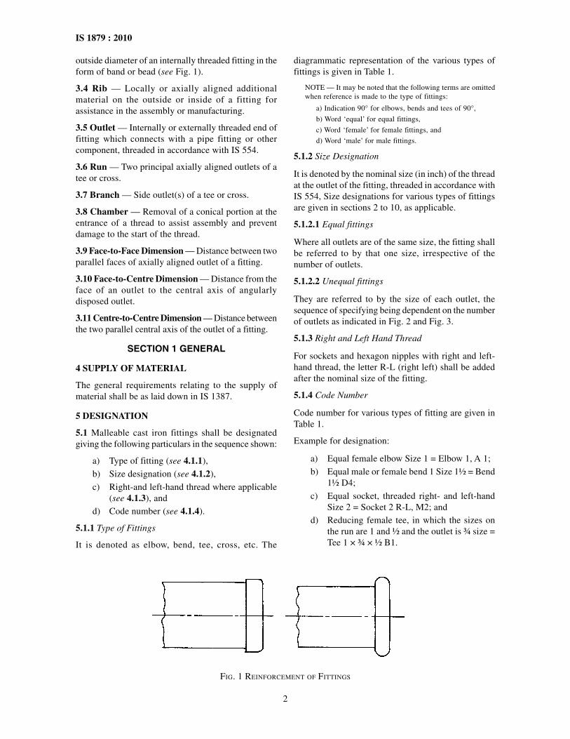
3.3 Reinforcement — An additional material at the
2
IS 1879 : 2010
outside diameter of an internally threaded fitting in theform of band or bead (see Fig. 1).
3.4 Rib — Locally or axially aligned additionalmaterial on the outside or inside of a fitting forassistance in the assembly or manufacturing.
3.5 Outlet — Internally or externally threaded end offitting which connects with a pipe fitting or othercomponent, threaded in accordance with IS 554.
3.6 Run — Two principal axially aligned outlets of atee or cross.
3.7 Branch — Side outlet(s) of a tee or cross.
3.8 Chamber — Removal of a conical portion at theentrance of a thread to assist assembly and preventdamage to the start of the thread.
3.9 Face-to-Face Dimension — Distance between twoparallel faces of axially aligned outlet of a fitting.
3.10 Face-to-Centre Dimension — Distance from theface of an outlet to the central axis of angularlydisposed outlet.
3.11 Centre-to-Centre Dimension — Distance betweenthe two parallel central axis of the outlet of a fitting.
SECTION 1 GENERAL
4 SUPPLY OF MATERIAL
The general requirements relating to the supply ofmaterial shall be as laid down in IS 1387.
5 DESIGNATION
5.1 Malleable cast iron fittings shall be designatedgiving the following particulars in the sequence shown:
a) Type of fitting (see 4.1.1),
b) Size designation (see 4.1.2),
c) Right-and left-hand thread where applicable(see 4.1.3), and
d) Code number (see 4.1.4).
5.1.1 Type of Fittings
It is denoted as elbow, bend, tee, cross, etc. The
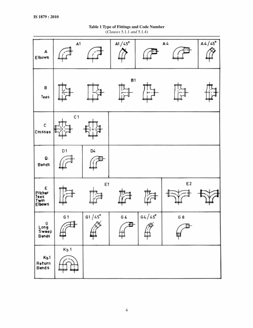
diagrammatic representation of the various types offittings is given in Table 1.
NOTE — It may be noted that the following terms are omittedwhen reference is made to the type of fittings:
a) Indication 90° for elbows, bends and tees of 90°,
b) Word ‘equal’ for equal fittings,
c) Word ‘female’ for female fittings, and
d) Word ‘male’ for male fittings.
5.1.2 Size Designation
It is denoted by the nominal size (in inch) of the threadat the outlet of the fitting, threaded in accordance withIS 554, Size designations for various types of fittingsare given in sections 2 to 10, as applicable.
5.1.2.1 Equal fittings
Where all outlets are of the same size, the fitting shallbe referred to by that one size, irrespective of thenumber of outlets.
5.1.2.2 Unequal fittings
They are referred to by the size of each outlet, thesequence of specifying being dependent on the numberof outlets as indicated in Fig. 2 and Fig. 3.
5.1.3 Right and Left Hand Thread
For sockets and hexagon nipples with right and left-hand thread, the letter R-L (right left) shall be addedafter the nominal size of the fitting.
5.1.4 Code Number
Code number for various types of fitting are given inTable 1.
Example for designation:
a) Equal female elbow Size 1 = Elbow 1, A 1;
b) Equal male or female bend 1 Size 1½ = Bend1½ D4;
c) Equal socket, threaded right- and left-handSize 2 = Socket 2 R-L, M2; and
d) Reducing female tee, in which the sizes onthe run are 1 and ½ and the outlet is ¾ size =Tee 1 × ¾ × ½ B1.
FIG. 1 REINFORCEMENT OF FITTINGS

3
IS 1879 : 2010
FIG. 2 METHODS FOR SPECIFYING OUTLETS OF UNEQUAL FITTINGS HAVING TWO OUTLETS
FIG. 3 METHODS FOR SPECIFYING OUTLETS OF UNEQUAL FITTINGS HAVING MORE THAN TWO OUTLETS
6 MATERIAL
6.1 The material used for the manufacture of malleablecast iron fittings shall conform to any of the gradespecified in IS 14329 as agreed to between themanufacturer and the purchaser.
6.2 Any other ferrous materials which give mechanicalproperties at least equivalent to those grades of malleablecast iron specified in 5.1 are allowed for fittings not largerthan size 3/8 of the straight type, but excluding unions.
7 DIMENSIONS AND DIMENSIONALTOLERANCES
7.1 Dimensions of various types of fittings shall be asspecified in Tables 2 to 28 in Sections 2 to 10, asapplicable.
NOTE — All the dimensions given in these sections enablethe fittings to be assembled with pipes threaded in accordancewith IS 554.
7.1.1 Fittings of sizes and dimensions other than thosespecified in Sections 2 to 10 may be supplied subjectto agreement between the purchaser and themanufacturer provided all other requirements asstipulated in this specification are fulfilled.
7.2 Wall thickness of fittings and tolerances on themshall be as given in Table 2.
7.3 In case of reducing fittings, the dimensions at eachoutlet shall be those appropriate to the nominal size ofthat outlet.
7.4 Where maximum or minimum dimensions are notspecified, the tolerances for centre-to-face, face-to-faceand centre-to-centre dimensions shall be as specifiedin Table 3.
7.5 Elbows, tees, crosses, sockets and caps may beeither plain or reinforced. Bends, pitcher, tees, twinelbows and long sweep fittings shall be reinforced. Theform of the reinforcement may be bend or bead andshall conform to the minimum dimensions given incol 5 and col 6 of Table 2.
7.6 The incorporation of a rib on any fitting is at theoption of the manufacturer but the projection of therib shall not exceed the projection of the reinforcement.
7.7 Two typical forms of female ends are shown inFig. 4. Either form may be used for code numbers D1,D4, E1, E2, G1, G1/45°, G4, G4/45° and Kb1.
FIG. 4 FORMS OF FEMALE ENDS
4
IS 1879 : 2010
Table 1 Type of Fittings and Code Number(Clauses 5.1.1 and 5.1.4)

5
IS 1879 : 2010
Table 1 (Concluded)

6
IS 1879 : 2010
Table 2 Details of Wall Thickness and Reinforcement of Fittings(Clauses 7.2 and 7.5)
Wall Thickness Reinforcement
Sl No. Size Designaion
Basic Size Tolerances1) Projection Width (1) (2) (3) (4) (5) (6)
i) ½ 2.0 –0.5 1.0 3.0 ii) ¼ 2.5 –0.5 1.3 3.6 iii) ? 2.5 –0.5 1.3 4.0 iv) ½ 2.5 –0.5 1.5 4.6 v) ¾ 3.0 –0.7 1.5 4.6
vi) 1 3.0 –0.7 1.8 5.1 vii) 1 ¼ 3.5 –0.7 1.8 5.1
viii) 1 ½ 3.5 –0.7 2.0 5.6 ix) 2 4.0 –1.7 2.3 6.1 x) 2 ½ 4.5 –1.0 2.5 6.1
xi) 3 5.0 –1.0 2.8 6.1 xii) 4 6.0 –1.0 3.3 7.1
xiii) 5 6.5 –1.0 4 8.1 xiv) 6 7.5 –1.0 4.6 8.9
1) No limit for plus tolerance.
Table 3 Tolerances(Clause 7.4)
Designations
Tolerances
Above Up to and Including
Sl No.
mm mm mm (1) (2) (3) (4)
i) — 30 ± 1.5 30 50 ± 2.0
ii) 50 75 ± 2.5 iii) 75 100 ± 3.0 iv) 100 150 ± 3.5 v) 150 200 ± 4.0
vi) 200 — ± 5.0
NOTES
1 Centre-to-face dimensions apply to elbows, bends, tees,crosses, etc.
2 Face-to-face dimensions apply to sockets nipples, etc.
3 Centre-to-centre dimensions apply to return bends.
8 THREADS
8.1 Outlets of fittings shall be threaded to dimensionsand the tolerances as specified in IS 554.
8.1.1 For checking conformity of threads, gaugingpractice in accordance with IS 8999 shall be followed.
8.2 Alignment of Threads
8.2.1 Tolerances for Alignment of Threads
The axes of the threads shall be coincident with thetheoretical axes of fitting within a tolerance of ± ½°on the run and on the branches.
8.3 Chamfering
The outlet of the fittings shall have a chamfer. The chamfershall preferably have an included angle of 90° ± 5° forinternal threads and 70 ± 10° for external threads. This,however, is for the purpose of guidance only.
8.3.1 Chamfering allowance should be provided whilechecking the threads with taper plug gauges. It shallbe minimum one pitch length.
9 FREEDOM FROM DEFECTS
On visual examination, the inside and outside surfacesof fittings shall be smooth and free from any defectssuch as cracks, injurious flaws, fin sand depth, etc.
10 GALVANIZING
Fittings shall be galvanized to meet the requirementsof IS 4759.
NOTE — For fittings supplied in other ferrous materials (see6.2) an alternate to zinc coating may be provided by agreementwith the purchaser.
11 PRESSURE TEST
11.1 The fittings before they leave the works, shall besubjected to either of the two following pressure tests,as mutually agreed between the purchaser and themanufacturer:
a) The application of an internal hydraulicpressure of not less than 2.1 MPa, or
b) The application of an internal air pressure of1.05 MPa whilst the fitting is completelyimmersed in water or light oil.
•

7
IS 1879 : 2010
11.1.1 The ends of fittings, when subjected to therequired pressure, the ends of fitting after having beenmade up wrench tight with the prior application oflubricant or sealant or by any other appropriate methodshall not show any leakage. The test shall be carriedout after the fittings have been screwed and before anyprotecting coating other than galvanizing has beenapplied.
11.1.2 The sample size an the acceptance criteria forthe pressure test shall be the same as for the repeatpressure test (see B-2.4 and Table 30).
11.2 Repeat Test
The purchaser or his representative shall have the rightto call for and be present at a repeat test at themanufacturer’s works. The sample size and acceptancecriteria for this test shall be as given in Annex B.
12 COMPRESSION TEST
12.1 This test shall be conducted to judge themalleability of the pipe fittings and shall be carriedout as follows:
A ring to the dimensions given below shall be cutfrom the end of the unfinished fittings after the heattreatment to form a test piece. The outside diameterof the test piece is measured over the points 45° offthe mould joints. The test piece shall be placed onthe equipment as shown in Fig. 5 (a hand vice maybe used in place), and shall be compressed graduallyat the rate of 17 to 20 mm/min until the amount ofcompression reaches 5 percent of the originaloutside diameter for fittings of size designation 2and below and 3 percent of the original diameterfor fittings above size designation 2. The test shallnot show any crack on any part of the test piece.
FIG. 5 EQUIPMENT FOR COMPRESSION TEST
Size designation ⅛ ¼ ⅜ ½ ¾ 1 1¼ 1½
Width of test 7 7 7 8 9 10 10 11piece, mm
Size designation 2 2½ 3 3½ 4 5 6
Width of test 12 13 15 16 17 18 20 piece, mm
12.1.1 Three samples of pie fitting for each of thefollowing categories of designation shall be taken forconducting compression test from each heat treatmentbatch:
a) Category 1, includes pipe fittings of sizedesignation upto 1;
b) Category 2, includes pipe fittings of sizedesignation from 1¼ to 2; and
c) Category 3, includes pipe fittings of sizedesignation over 2.
13 SAMPLING
The requirements for sampling and criteria forconformity shall be as given in Annex B.
14 MARKING
14.1 Each fitting shall be marked with themanufacturer’s name or trade-mark, and the sizedesignation.
14.2 Each packing containing fittings shall carry thefollowing, stamped or written in indelible ink:
a) Manufacturer’s name or trade-mark,b) Designation of fittings, andc) Lot number or any other mark for tracing the
manufacturing details.
14.3 BIS Certification Marking
Each fitting may also be marked with the Standard Mark.

8
IS 1879 : 2010
14.3.1 The use of Standard Mark is governed by theprovisions of the Bureau of Indian Standards Act, 1986 andthe Rules and Regulations made thereunder. The details of
conditions under which the licence for the use of StandardMark may be granted to manufacturers or producers maybe obtained from the Bureau of Indian Standards.
Za1
SECTION 2 ELBOWS
Table 4 Size Designation, Dimensions and Mass of Elbows A1, Male and Female Elbows A4,and Side Outlet Elbows Za1
(Clause 7.1)
Size Designation Dimensions Nominal Mass (kg/100 Pieces)
A1 A4 Za1 a b A1 A4 Zal (1) (2) (3) (4) (5) (6) (7) (8)
— 19 25 3.0 2.5 — ¼ ¼ — 21 28 4.5 4.0 — ? ? ? 25 32 6.1 5.9 — ½ ½ ½ 28 37 9.1 9.4 — ¾ ¾ ¾ 33 43 13.7 14.5 — 1 1 1 38 52 20.9 22.8 — 1¼ 1¼ 1¼ 45 60 33.2 35.8 — 1½ 1½ 1½ 50 65 42.7 46.3 — 2 2 2 58 74 65.2 70.7 — 2½ 2½ — 69 88 117.0 124.0 — 3 3 — 78 98 153.0 165.0 — 4 4 — 96 118 270.0 305.0 — 5 — — 115 — 480.0 — — 6 ½ — 131 — 660.0 — —
⅛
⅛ ⅜ ⅜ ⅜
9
IS 1879 : 2010
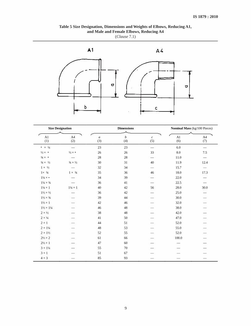
Table 5 Size Designation, Dimensions and Weights of Elbows, Reducing A1,and Male and Female Elbows, Reducing A4
(Clause 7.1)
Size Designation
Dimensions Nominal Mass (kg/100 Pieces)
A1 A4 a b c A1 A4 (1) (2) (3) (4) (5) (6) (7)
? × ¼ — 23 23 — 6.0 —
½ × ? ½ × ? 26 26 33 8.0 7.5
¾ × ? — 28 28 — 11.0 —
¾ × ½ ¾ × ½ 30 31 40 11.9 12.4
1 × ½ — 32 34 — 15.7 —
1× ¾ 1 × ¾ 35 36 46 18.0 17.3
1¼ × ? — 34 39 — 22.0 —
1¼ × ¾ — 36 41 — 22.5 —
1¼ × 1 1¼ × 1 40 42 56 28.0 30.0
1½ × ½ — 36 42 — 25.0 —
1½ × ¾ — 39 44 — 30.0 —
1½ × 1 — 42 46 — 32.0 —
1½ × 1¼ — 46 48 — 38.0 —
2 × ½ — 38 48 — 42.0 —
2 × ¼ — 41 50 — 47.0 —
2 × 1 — 44 51 — 52.0 —
2 × 1¼ — 48 53 — 55.0 —
2 × 1½ — 52 55 — 52.0 —
2½ × 2 — 61 66 — 100.0 —
2½ × 1 — 47 60 — — —
3 × 1¼ — 55 70 — — —
3 × 1 — 51 67 — — —
4 × 3 — 85 93 — — —
•
•
• • •

10
IS 1879 : 2010
Table 6 Size Designation, Dimensions and Mass of 45° Elbows A1/45° and 45°Male and Female Elbows A4/45°
(Clause 7.1)
Size Designation Dimensions Nominal Mass (kg/100 Pieces)
A1/45° A4/45° a b A1/45° A4/45°
(1) (2) (3) (4) (5) (6)
3/8 ? 20 25 5.3 5.4 ½ ½ 22 28 6.9 7.8 ¾ ¾ 25 32 11.5 12.2 1 1 28 37 15.5 18.0
1¼ 1¼ 33 43 26.0 29.0 1½ 1½ 36 46 34.0 35.0 2 2 43 55 48.0 50.0
Table 7 Size Designation, Dimensions and Weightsof Twin Elbows E2
(Clause 7.1)
Size Designation Dimensions Nominal Mass E2 a (kg/100 Pieces) mm
(1) (2) (3)
3/8 36 12.7 ½ 45 18.9 ¾ 50 27.3 1 63 41.0
1 ¼ 76 64.8 1 ½ 85 90.3 2 102 140.0
Table 8 Size Designation, Dimensions and Weightsof Twin Elbows, Reducing E2
(Clause 7.1)
Size Designation Dimensions
Nominal Mass (kg/100 Pieces)
E2 a b mm mm
(1) (2) (3) (4)
¾ × ½ × 1/3 47 48 19.2 1 × ½ × ½ 49 51 25.0 1 × ¾ × ¾ 53 54 33.8 1 ¼ × ¾ × ¾ 55 58 42.0 1¼ × 1 × 1 66 68 42.9 1½ × 1 × 1 66 71 68.0 1½ × 1¼ × 1¼ 77 79 84.4 2 × 1¼ × 1/3 80 85 101.0 2 × 1½ × 1½ 91 94 112.0
•
• •
•

11
IS 1879 : 2010
Table 9 Size Designation, Dimensions and Mass of Union Elbows, Flat Seat UA1,Male and Female Union Elbows, Flat Seat UA2, Union Elbows, Taper Seat UA11,
and Male and Female Union Elbows, Taper Seat UA12(Clause 7.1)
Size Designation Dimensions
Nominal Mass (kg/100 Pieces)
UA1 UA2 UA11 UA12 a b c UA1 UA2 UA11 UA12 mm mm mm
(1) (2) (3) (4) (5) (6) (7) (8) (9) (10) (11)
— — ¼ ¼ 48 61 21 — — 10.1 11.3 3/8 3/8 3/8 3/8 52 65 25 13.6 15.2 13.7 15.8 ½ ½ ½ ½ 58 76 28 22.6 25.2 23.3 26.5 3/4 3/4 3/4 3/4 62 82 33 35.0 39.2 36.5 40.4 1 1 1 1 72 94 38 48.6 55.0 49.7 53.5
1¼ 1¼ 1 ¼ 1¼ 82 107 45 78.7 88.4 82.0 92.6 1½ 1½ 1½ 1½ 90 115 50 97.0 109.0 100.0 115.0 2 2 2 2 100 128 58 150.0 167.0 155.0 172.0

12
IS 1879 : 2010
SECTION 3 TEES
Table 10 Size Designation, Dimensions and Mass of Tees B1, and Side Outlet Tees Za2(Clause 7.1)
Size Designation Dimensions Nominal Mass (kg/100 Pieces)
B1 Za2 a B1 Za2 mm
(1) (2) (3) (4) (5)
1/8 — 19 4.2 — ¼ — 21 6.5 —
3/8 3/8 25 8.5 10.4 ½ ½ 28 13.0 14.7 ¾ ¾ 33 18.7 23.4 1 1 38 28.2 32.6
1¼ 1¼ 45 43.5 51.3 1½ 1½ 50 57.0 66.0 2 2 58 88.0 99.0
2½ — 69 155.0 — 3 — 78 210.0 — 4 — 96 345.0 — 5 — 115 640.0 — 6 — 131 780.0 —
13
IS 1879 : 2010
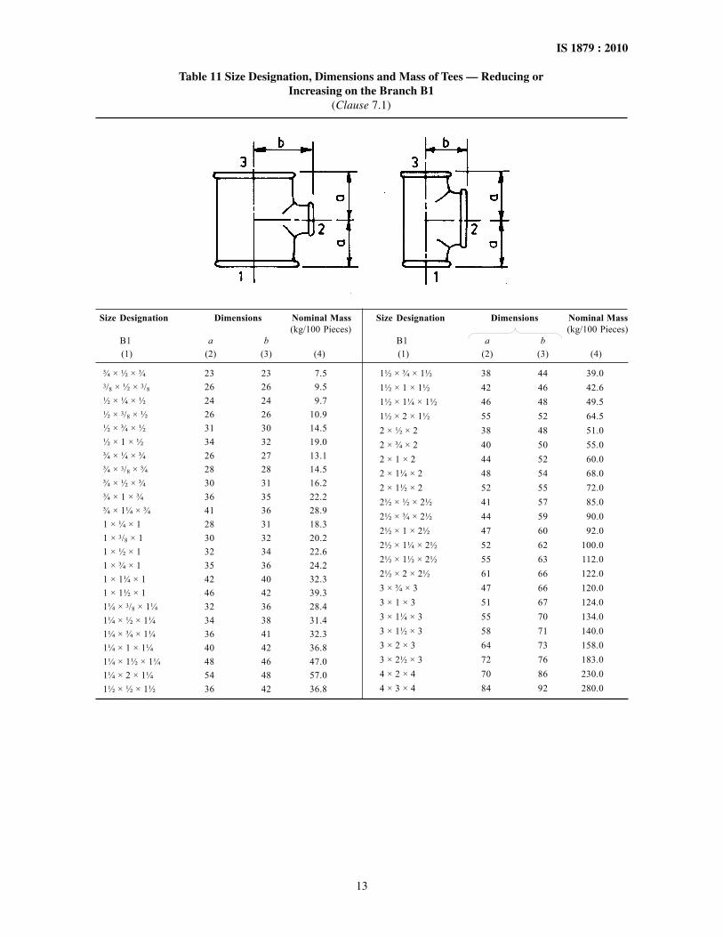
Table 11 Size Designation, Dimensions and Mass of Tees — Reducing orIncreasing on the Branch B1
(Clause 7.1)
Size Designation Dimensions Nominal Mass(kg/100 Pieces)
B1 a b (1) (2) (3) (4)
¾ × ½ × ¾ 23 23 7.53/8 × ½ × 3/8 26 26 9.5½ × ¼ × ½ 24 24 9.7½ × 3/8 × ½ 26 26 10.9½ × ¾ × ½ 31 30 14.5½ × 1 × ½ 34 32 19.0¾ × ¼ × ¾ 26 27 13.1¾ × 3/8 × ¾ 28 28 14.5¾ × ½ × ¾ 30 31 16.2¾ × 1 × ¾ 36 35 22.2¾ × 1¼ × ¾ 41 36 28.91 × ¼ × 1 28 31 18.31 × 3/8 × 1 30 32 20.21 × ½ × 1 32 34 22.61 × ¾ × 1 35 36 24.21 × 1¼ × 1 42 40 32.31 × 1½ × 1 46 42 39.31¼ × 3/8 × 1¼ 32 36 28.41¼ × ½ × 1¼ 34 38 31.41¼ × ¾ × 1¼ 36 41 32.31¼ × 1 × 1¼ 40 42 36.81¼ × 1½ × 1¼ 48 46 47.01¼ × 2 × 1¼ 54 48 57.01½ × ½ × 1½ 36 42 36.8
Size Designation Dimensions Nominal Mass(kg/100 Pieces)
B1 a b (1) (2) (3) (4)
1½ × ¾ × 1½ 38 44 39.01½ × 1 × 1½ 42 46 42.61½ × 1¼ × 1½ 46 48 49.51½ × 2 × 1½ 55 52 64.52 × ½ × 2 38 48 51.02 × ¾ × 2 40 50 55.02 × 1 × 2 44 52 60.02 × 1¼ × 2 48 54 68.02 × 1½ × 2 52 55 72.02½ × ½ × 2½ 41 57 85.02½ × ¾ × 2½ 44 59 90.02½ × 1 × 2½ 47 60 92.02½ × 1¼ × 2½ 52 62 100.02½ × 1½ × 2½ 55 63 112.02½ × 2 × 2½ 61 66 122.03 × ¾ × 3 47 66 120.03 × 1 × 3 51 67 124.03 × 1¼ × 3 55 70 134.03 × 1½ × 3 58 71 140.03 × 2 × 3 64 73 158.03 × 2½ × 3 72 76 183.04 × 2 × 4 70 86 230.04 × 3 × 4 84 92 280.0
14
IS 1879 : 2010
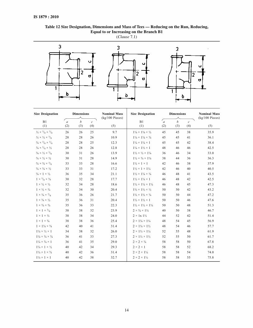
Table 12 Size Designation, Dimensions and Mass of Tees — Reducing on the Run, Reducing,Equal to or Increasing on the Branch B1
(Clause 7.1)
Size Designation Dimensions Nominal Mass(kg/100 Pieces)
B1 a b c(1) (2) (3) (4) (5)
½ × 3/8 × 3/8 26 26 25 9.7½ × ½ × 3/8 28 28 26 10.9¾ × 3/8 × 3/8 28 28 25 12.3¾ × 3/8 × ½ 28 28 26 12.8¾ × ½ × 3/8 30 31 26 13.9¾ × ½ × ½ 30 31 28 14.9¾ × ¾ × 3/8 33 33 28 16.6¾ × ¾ × ½ 33 33 31 17.2¾ × 1 × ½ 36 35 34 21.11 × 3/8 × ¾ 30 32 28 17.71 × ½ × ½ 32 34 28 18.61 × ½ × ¾ 32 34 30 20.41 × ¾ × 3/8 35 36 26 21.71 × ¾ × ½ 35 36 31 20.41 × ¾ × ¾ 35 36 33 22.31 × 1 × 3/8 38 38 32 23.91 × 1 × ½ 38 38 34 24.01 × 1 × ¾ 38 38 36 25.41 × 1¼ × ¾ 42 40 41 31.41¼ × ½ × 1 34 38 32 26.01¼ × ¾ × ¾ 36 41 33 27.31¼ × ¾ × 1 36 41 35 29.01¼ × 1 × ½ 40 42 34 29.31¼ × 1 × ¾ 40 42 36 31.41¼ × 1 × 1 40 42 38 32.7
Size Designation Dimensions Nominal Mass(kg/100 Pieces)
B1 a b c(1) (2) (3) (4) (5)
1¼ × 1¼ × ½ 45 45 38 35.91¼ × 1¼ × ¾ 45 45 41 36.11¼ × 1¼ × 1 45 45 42 38.41¼ × 1½ × 1 48 46 46 42.51½ × ½ × 1¼ 36 46 34 33.01½ × ¾ × 1¼ 38 44 36 36.31½ × 1 × 1 42 46 38 37.91½ × 1 × 1¼ 42 46 40 40.51½ × 1¼ × ¾ 46 48 41 43.51½ × 1¼ × 1 46 48 42 42.51½ × 1¼ × 1¼ 46 48 45 47.31½ × 1½ × ½ 50 50 42 43.21½ × 1½ × ¾ 50 50 44 47.21½ × 1½ × 1 50 50 46 47.61½ × 1½ × 1¼ 50 50 48 51.32 × ¾ × 1½ 40 50 38 46.72 × 1x 1½ 44 52 42 51.42 × 1¼ × 1¼ 48 54 45 56.92 × 1¼ × 1½ 48 54 46 57.72 × 1½ × 1¼ 52 55 48 61.92 × 1½ × 1½ 52 55 50 61.72 × 2 × ¾ 58 58 50 67.82 × 2 × 1 58 58 52 68.22 × 2 × 1¼ 58 58 54 74.02 × 2 × 1½ 58 58 55 75.8

15
IS 1879 : 2010
Table 13 Size Designation, Dimensions and Mass of Pitcher Tees E1(Clause 7.1)
Size Designation
Dimensions Nominal Mass (kg/100 Pieces)
E1 a c
mm mm (1) (2) (3) (4)
3/8 36 19 11.6
½ 45 24 17.8 ¾ 50 28 25.2
1 63 33 38.0
1¼ 76 40 60.7 1½ 85 43 83.4
2 102 53 129.0
Size Designation Dimensions Nominal MassE1 (kg/100 Pieces)
a b c(1) (2) (3) (4) (5)
1¼ × 1 × 1¼ 66 68 36 50.31¼ × 1¼ × 1 76 76 38 57.01½ × ¾ × 1½ 55 61 33 53.41½ × 1 × 1¼ 66 71 36 60.81½ × 1 × 1½ 66 71 36 60.01½ × 1¼ × 1 77 79 38 68.61½ × 1¼ × 1¼ 77 79 40 74.41½ × 1¼ × 1½ 77 79 41 75.12 × 1 × 2 70 77 40 82.12 × 1¼ × 1½ 80 85 41 86.82 × 1¼ × 2 80 85 45 94.92 × 1½ × 1¼ 91 94 43 95.02 × 1½ × 1½ 91 94 43 102.02 × 1½ × 2 91 94 48 104.0
Size Designation Dimensions Nominal MassE1 (kg/100 Pieces)
a b c(1) (2) (3) (4) (5)
¾ × ½ × ½ 47 48 24 19.6¾ × ½ × ¾ 47 48 25 21.1¾ × ¾ × ½ 50 50 27 24.21 × ½ × ¾ 49 51 25 26.61 × ½ × 1 49 51 28 27.91 × ¾ × ½ 53 54 27 30.71 × ¾ × ¾ 53 54 28 31.61 × ¾ × 1 53 54 30 32.41 × 1 × ¾ 63 63 31 40.01¼ × ½ × 1¼ 51 56 30 38.31¼ × ¾ × 1 55 58 30 41.71¼ × ¾ × 1¼ 55 58 33 44.91¼ × 1 × ¾ 66 68 31 47.21¼ × 1 × 1 66 68 33 45.5
Table 14 Size Designation, Dimensions and Mass of Pitcher Tees — Reducing on the Branch, Reducingon the Run and Reducing on Branch and Run E1
(Clause 7.1)
16
IS 1879 : 2010
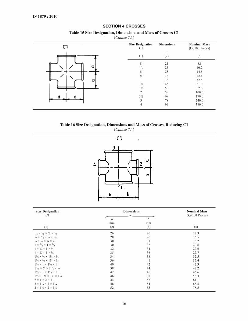
SECTION 4 CROSSES
Table 15 Size Designation, Dimensions and Mass of Crosses C1(Clause 7.1)
Table 16 Size Designation, Dimensions and Mass of Crosses, Reducing C1(Clause 7.1)
Size Designation Dimensions Nominal MassC1 (kg/100 Pieces)
a bmm mm
(1) (2) (3) (4)1/3 × 3/8 × ½ × 3/8 26 26 12.3¾ × 3/8 × ¾ × 3/8 28 26 16.5¾ × ½ × ¾ × ½ 30 31 18.21 × 3/8 × 1 × 3/8 30 32 20.61 × ½ × 1 × ½ 32 34 22.61 × ¾ × 1 × ¾ 35 36 27.71¼ × ½ × 1¼ × ½ 34 38 32.51¼ × ¾ × 1¼ × ¾ 36 41 35.41¼ × 1 × 1¼ × 1 40 42 42.311/3 × ¾ × 11/3 × ¾ 38 44 42.21½ × 1 × 1½ × 1 42 46 46.61½ × 1¼ × 1½ × 1¼ 46 38 55.32 × 1 × 2 × 1 44 52 64.12 × 1¼ × 2 × 1¼ 48 54 68.52 × 1½ × 2 × 1½ 52 55 78.5
Size Designation Dimensions Nominal MassC1 (kg/100 Pieces)
a(1) (2) (3)
¼ 21 8.83/8 25 10.2½ 28 14.5¾ 33 22.41 38 32.8
1¼ 45 51.01½ 50 62.02 58 100.0
2½ 69 170.03 78 240.04 96 380.0
17
IS 1879 : 2010
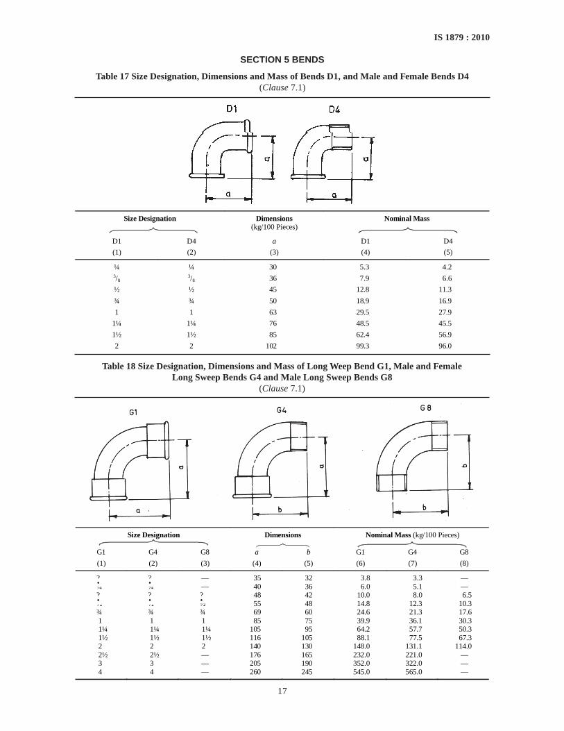
SECTION 5 BENDS
Table 17 Size Designation, Dimensions and Mass of Bends D1, and Male and Female Bends D4(Clause 7.1)
Size Designation
Dimensions (kg/100 Pieces)
Nominal Mass
D1 D4 a D1 D4
(1) (2) (3) (4) (5)
¼ ¼ 30 5.3 4.2 3/8
3/8 36 7.9 6.6
½ ½ 45 12.8 11.3
¾ ¾ 50 18.9 16.9
1 1 63 29.5 27.9
1¼ 1¼ 76 48.5 45.5
1½ 1½ 85 62.4 56.9
2 2 102 99.3 96.0
Table 18 Size Designation, Dimensions and Mass of Long Weep Bend G1, Male and FemaleLong Sweep Bends G4 and Male Long Sweep Bends G8
(Clause 7.1)
Size Designation Dimensions
Nominal Mass (kg/100 Pieces)
G1 G4 G8 a b G1 G4 G8
(1) (2) (3) (4) (5) (6) (7) (8)
? ? — 35 32 3.8 3.3 — ¼ ¼ — 40 36 6.0 5.1 — ? ? ? 48 42 10.0 8.0 6.5 ½ ½ ½ 55 48 14.8 12.3 10.3 ¾ ¾ ¾ 69 60 24.6 21.3 17.6 1 1 1 85 75 39.9 36.1 30.3 1¼ 1¼ 1¼ 105 95 64.2 57.7 50.3 1½ 1½ 1½ 116 105 88.1 77.5 67.3 2 2 2 140 130 148.0 131.1 114.0 2½ 2½ — 176 165 232.0 221.0 — 3 3 — 205 190 352.0 322.0 — 4 4 — 260 245 545.0 565.0 —
• • •
• •

18
IS 1879 : 2010
Table 19 Size Designation, Dimensions and Mass of 45° Long Sweep Bends G1/45° andMale and Female Long Weep Bends G4/45°
(Clause 7.1)
Size Designation Dimensions
Nominal Mass (kg/100 Pieces)
G1/45° G4/45° a b G1/45° G4/45°
(1) (2) (3) (4) (5) (6)
¼ ¼ 26 21 4.9 3.7 3/8
3/8 30 24 7.6 5.9 ½ ½ 36 30 11.7 9.2 ¾ ¾ 43 36 18.1 14.8 1 1 51 42 29.5 24.1 1¼ 1¼ 64 54 48.5 39.8 1½ 1½ 68 58 61.2 50.9 2 2 81 70 97.2 81.8 2? 2? 99 86 154.0 137.0 3 3 113 100 211.0 194.0
Table 20 Size Designation, Dimensions and Mass of Return Bends Kb1(Clause 7.1)
Size Designation Dimensions a
Nominal Mass (kg/100 Pieces)
mm (1) (2) (3)
½ 38 17.7 ¾ 50 26.6 1 64 42.1
1¼ 76 69.0 1½ 89 97.7 2 102 141.0
• •
19
IS 1879 : 2010
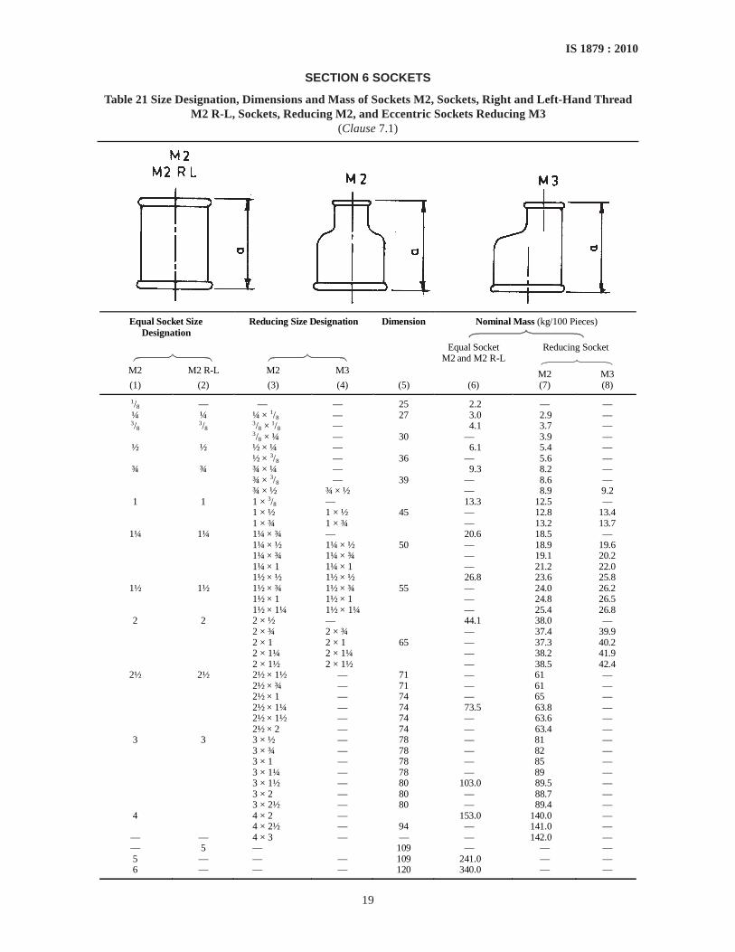
SECTION 6 SOCKETS
Table 21 Size Designation, Dimensions and Mass of Sockets M2, Sockets, Right and Left-Hand ThreadM2 R-L, Sockets, Reducing M2, and Eccentric Sockets Reducing M3
(Clause 7.1)
Equal Socket Size Designation
Reducing Size Designation Dimension Nominal Mass (kg/100 Pieces)
Reducing Socket
M2
M2 R-L
M2
M3
Equal Socket M2 and M2 R-L
M2 M3 (1) (2) (3) (4) (5) (6) (7) (8)
1/8 — — — 25 2.2 — — ¼ ¼ ¼ × 1/8 — 27 3.0 2.9 — 3/8 3/8 3/8 × 1/8 — 4.1 3.7 — 3/8 × ¼ — 30 — 3.9 —
½ ½ ½ × ¼ — 6.1 5.4 — ½ × 3/8 — 36 — 5.6 —
¾ ¾ ¾ × ¼ — 9.3 8.2 — ¾ × 3/8 — 39 — 8.6 — ¾ × ½ ¾ × ½ — 8.9 9.2 1 1 1 × 3/8 — 13.3 12.5 — 1 × ½ 1 × ½ 45 — 12.8 13.4 1 × ¾ 1 × ¾ — 13.2 13.7
1¼ 1¼ 1¼ × ¾ — 20.6 18.5 — 1¼ × ½ 1¼ × ½ 50 — 18.9 19.6 1¼ × ¾ 1¼ × ¾ — 19.1 20.2 1¼ × 1 1¼ × 1 — 21.2 22.0 1½ × ½ 1½ × ½ 26.8 23.6 25.8
1½ 1½ 1½ × ¾ 1½ × ¾ 55 — 24.0 26.2 1½ × 1 1½ × 1 — 24.8 26.5 1½ × 1¼ 1½ × 1¼ — 25.4 26.8 2 2 2 × ½ — 44.1 38.0 — 2 × ¾ 2 × ¾ — 37.4 39.9 2 × 1 2 × 1 65 — 37.3 40.2 2 × 1¼ 2 × 1¼ — 38.2 41.9 2 × 1½ 2 × 1½ — 38.5 42.4
2½ 2½ 2½ × 1½ — 71 — 61 — 2½ × ¾ — 71 — 61 — 2½ × 1 — 74 — 65 — 2½ × 1¼ — 74 73.5 63.8 — 2½ × 1½ — 74 — 63.6 — 2½ × 2 — 74 — 63.4 — 3 3 3 × ½ — 78 — 81 — 3 × ¾ — 78 — 82 — 3 × 1 — 78 — 85 — 3 × 1¼ — 78 — 89 — 3 × 1½ — 80 103.0 89.5 — 3 × 2 — 80 — 88.7 — 3 × 2½ — 80 — 89.4 — 4 4 × 2 — 153.0 140.0 — 4 × 2½ — 94 — 141.0 —
— — 4 × 3 — — — 142.0 — — 5 — 109 — — — 5 — — — 109 241.0 — — 6 — — — 120 340.0 — —
20
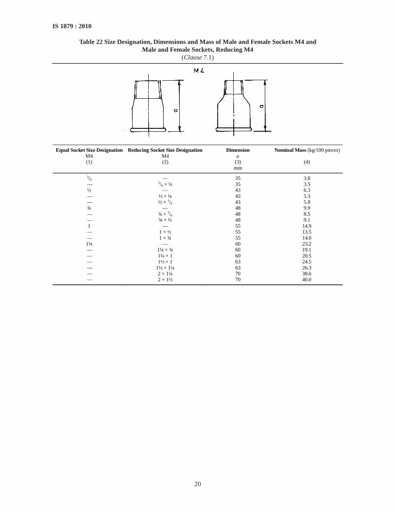
IS 1879 : 2010
Table 22 Size Designation, Dimensions and Mass of Male and Female Sockets M4 andMale and Female Sockets, Reducing M4
(Clause 7.1)
Equal Socket Size Designation M4
Reducing Socket Size Designation M4
Dimension a
Nominal Mass (kg/100 pieces)
(1) (2) (3) (4) mm
3/8 — 35 3.8 — 3/8 × ¼ 35 3.5 ½ — 43 6.3 — ½ × ¼ 43 5.3 — ½ × 3/8 43 5.8 ¾ — 48 9.9 — ¾ × 3/8 48 8.5 — ¾ × ½ 48 9.1 1 — 55 14.9
— 1 × ½ 55 13.5 — 1 × ¾ 55 14.0 1¼ — 60 23.2 — 1¼ × ¾ 60 19.1 — 1¼ × 1 60 20.5 — 1½ × 1 63 24.5 — 1½ × 1¼ 63 26.3 — 2 × 1¼ 70 38.6 — 2 × 1½ 70 40.0

21
IS 1879 : 2010
Size Designation Pattern Dimensions Nominal Mass(kg/100 Pieces)
N4 a bmm mm
(1) (2) (3) (4) (5)
¼ × 1/8 I 20 — 1.23/8 × 1/8 II 20 — 2.13/8 × ¼ I 20 — 1.4½ × 1/8 II 24 — 3.5½ × ¼ II 24 — 3.2½ × 3/8 I 24 — 2.4¾ × ¼ II 26 — 6.2¾ × 3/8 II 26 — 5.8¾ × ½ I 26 — 4.71 × ¼ II 29 — 10.61 × 3/8 II 29 — 10.51 × ½ II 29 — 9.41 × ¾ I 29 — 7.51¼ × 1/8 II 31 — 17.41¼ × ½ II 31 — 17.81¼ × ¾ II 31 — 16.01¼ × 1 I 31 — 12.01½ × 3/8 II 31 — 22.41½ × ½ II 31 — 24.61½ × ¾ II 31 — 22.01½ × 1 II 31 — 18.71½ × 1¼ I 31 — 10.52 × ½ III 35 48 34.82 × ¾ III 35 48 36.92 × 1 II 35 — 40.02 × 1¼ II 35 — 34.62 × 1½ II 35 — 27.32½ × 1 III 40 54 59.32½ × 1¼ III 40 54 59.52½ × 1½ II 40 — 61.02½ × 2 II 40 — 46.33 × 1 III 44 59 97.63 × 1¼ III 44 59 94.93 × 1½ III 44 59 90.33 × 2 II 44 59 88.33 × 2½ II 44 — 56.43½ × 3 II 46 — —4 × 2 III 51 69 164.04 × 2½ III 51 69 150.04 × 3 II 51 — 132.04 × 3½ II 51 — —
SECTION 7 BUSHING AND HEXAGON NIPPLES
Table 23 Size Designation, Dimensions and Mass of Bushing N4(Clasue 7.1)
22
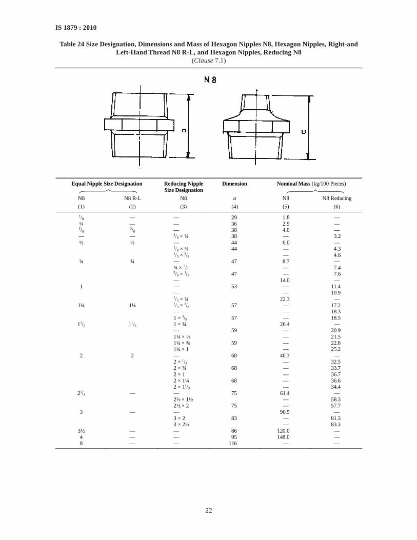
IS 1879 : 2010
Table 24 Size Designation, Dimensions and Mass of Hexagon Nipples N8, Hexagon Nipples, Right-andLeft-Hand Thread N8 R-L, and Hexagon Nipples, Reducing N8
(Clause 7.1)
Equal Nipple Size Designation Reducing Nipple Size Designation
Dimension Nominal Mass (kg/100 Pieces)
N8 N8 R-L N8 a N8 N8 Reducing
(1) (2) (3) (4) (5) (6)
1/8 — — 29 1.8 — ¼ — — 36 2.9 — 3/8
3/8 — 38 4.0 — — — 3/8 × ¼ 38 — 3.2 ½ ½ — 44 6.0 — 1/8 × ¼ 44 — 4.3 1/3 × 3/8 — 4.6
¾ ¾ — 47 8.7 — ¾ × 3/8 — 7.4 3/8 × 1/3 47 — 7.6 — 14.0 — 1 — 53 — 11.4 — — 10.9 1/3 × ¾ 22.3 —
1¼ 1¼ 1/3 × 3/8 57 — 17.2 — — 18.3 1 × 3/8 57 — 18.5
11/3 11/3 1 × ¾ 26.4 — — 59 — 20.9 1¼ × ½ — 21.5 1¼ × ¾ 59 — 22.8 1¼ × 1 — 25.2 2 2 — 68 40.3 — 2 × 1/3 — 32.5 2 × ¾ 68 — 33.7 2 × 1 — 36.7 2 × 1¼ 68 — 36.6 2 × 11/3 — 34.4
21/3 — — 75 61.4 — 2½ × 1½ — 58.3 2½ × 2 75 — 57.7 3 — — 90.5 — 3 × 2 83 — 81.3 3 × 2½ — 83.3
3½ — — 86 120.0 — 4 — — 95 148.0 — 8 — — 116 — —

23
IS 1879 : 2010
SECTION 8 BACKNUTS
Table 25 Size Designation, Dimensions and Mass of Backnuts P41)
Size Designation P4
Dimension a
Min
Nominal Mass (kg/100 Pieces)
mm (1) (2) (3)
¼ 6 1.3 3/8 7 2.0 1/3 8 3.4 ¾ 9 4.3 1 10 8.3
1¼ 11 11.9 1½ 12 13.2 2 13 22.6
2½ 16 41.8 3 19 53.0
1) Backnuts may be plain recessed, and one face may be machined.
SECTION 9 CAPS AND PLUGS
Table 26 Size Designation, Dimensions and Mass of Hexagon Caps T1; Round Caps T2;Plain Plugs T8; Beaded Plugs; T9, and Countersunk Plugs T11
(Clause 7.1)
Size Desingnation
Dimensions, Min Nominal, Max (kg/100 Pieces)
T1 T2 T8 T9 T11 a b c d T1 T2 T8 T9 T111) mm mm mm mm
(1) (2) (3) (4) (5) (6) (7) (8) (9) (10) (11) (12) (13) (14)
— 1/8 1/8 1/8 — 13 11 20 — — 1.4 — 1.2 — ¼ ¼ ¼ ¼ — 15 14 22 — 2.1 2.1 — 2.0 — 3/8
3/8 3/8
3/8 3/8 17 15 24 11 2.9 2.9 — 2.6 —
½ ½ ½ ½ ½ 19 18 26 15 4.3 4.3 — 3.8 — ¾ ¾ ¾ ¾ ¾ 22 20 32 16 7.0 7.0 — 7.2 — 1 1 1 1 1 24 23 36 19 10.2 10.2 — 10.6 —
1¼ 1¼ 1¼ 1¼ — 27 29 39 — 16.4 16.4 — 17.0 — 1½ 1½ 1½ 1½ — 27 30 41 — 21.3 21.3 — 21.2 — 2 2 2 2 — 32 36 48 — 32.0 32.0 — 34.3 —
2½ — 2½ 2½ — 35 39 54 — 53.5 — — 57.6 — 3 — 3 3 — 38 44 60 — 80.5 — — 77.6 — — — — 3½ — — — 67 — — — — 100.0 — 4 — 4 4 — 45 58 70 — 132.0 — — 124.0 —
NOTE — Plugs with size designation 1/8, ¼, 3/8 are supplied in solid type only. Plugs with size designation ½ and above may be eithersolid or hollow but manufacturers normally supply hollow unless otherwise specified.
1) The weight will be included later on.

24
IS 1879 : 2010
SECTION 10 UNIONS
Table 27 Size Designation, Dimensions and Mass of Unions, Flat Seat U1; Male and Female Unions, FlatSeat U2; Unions, Taper Seat U11 and Male and Female Unions Taper Seat U12
(Clause 7.1)
Size Designation
Dimensions
Nominal Mass (kg/100 Pieces)
U1 U2 U11 U12 a b U1 U2 U11 U12 mm mm
(1) (2) (3) (4) (5) (6) (7) (8) (9) (10) 1/8 — 1/8 — 38 — 6.2 — 6.8 — ¼ ¼ ¼ ¼ 42 55 8.1 8.3 8.4 9.4 3/8 3/8 3/8 3/8 45 58 11.4 11.9 12.1 12.1 ½ ½ ½ ½ 48 66 19.1 20.0 19.4 25.0 ¾ ¾ ¾ ¾ 52 72 26.7 30.3 27.1 31.0 1 1 1 1 58 80 34.8 40.1 35.1 40.0
1¼ 1¼ 1¼ 1¼ 65 90 58.2 67.7 60.1 70.5 1½ 1½ 1½ 1½ 70 95 73.3 85.5 73.5 89.0 2 2 2 2 78 106 109.0 126.0 115.0 128.0
2½ — 2½ 2½ 85 118 176.0 — 176.0 209.0 3 — 3 3 95 130 244.0 — 250.0 286.0 4 — 4 — 110 — 390.0 — 400 — 5 — — — 135 — 795.0 — — — 6 — — — 150 — 1 100.0 — — —

25
IS 1879 : 2010
Table 28 Gasket for Unions, Flat Set U1, U2, UA1 and UA2(Clause 7.1)
Fitness Sizes of Unions Diameters of Gasket, mm Thread Sizes or Union Nuts (for Guidance Only)
d D (1) (2) (3) (4)
? — — G ½ ¼ 13 20 G ½ 17 24 G ½
? 17 24 G ½ 19 27 G ½
½ 21 30 G 1 24 34 G 1½
¾ 27 38 G 1½ 1 32 44 G 1½
1¼ 42 55 G 2 1½ 46 62 G 2½ 2 60 78 G 2½
2½ 75 97 G 3½ 3 88 110 G 4 4 113 135 G 5 120 148 G 5½
NOTE — Material and thickness of gasket to be specified when ordering, depending on the application.
ANNEX A(Clause 3.2)
NOMINAL SIZES OF PIPE THREADS AND CORRESPONDING NOMINAL DIAMETER, DN
Nominal Size of Pipe Threads Corresponding Nominal Bore (Size Designation) mm
1/8 6¼ 83/8 10½ 15¾ 201 251¼ 321½ 402 502½ 653 804 1005 1256 150
1/8
3/8

26
IS 1879 : 2010
ANNEX B(Clauses 11.1.2, 11.2 and 13)
SAMPLING OF MALLEABLE CAST IRON PIPE FITTINGS
B-1 LOT
All the malleable cast iron pipe fittings of the sametype and manufactured from the same cast of metalshall be grouped together to form a lot.
B-2 SELECTION OF SAMPLES
B-2.1 Sample Size of Visual and DimensionalCharacteristics
Those cast iron fittings which are complicated in designshall be individually examined for visualcharacteristics, such as reinforcement, threads andfinish. For other cast iron fittings, the visualexamination shall be done on sample pieces. The visualexamination shall include verification for material,freedom from surface defects, finish ad spanner sizes(wherever applicable). After completing the visualexamination, the fittings shall be inspected fordimensions including tolerances, short dimensions andmass for 100 pieces. The sample sizes and criteria foracceptance of the lot for these characteristics are givenin Table 29.
B-2.2 Scale of Sampling for Repeat Pressure Tests
If the lot has been successfully tested for visual anddimensional characteristics, sample fittings form eachlot shall be selected at random for conducting repeatpressure test. The sample sizes and criteria for
acceptance of lot in respect of these characteristics aregiven in Table 30.
B-2.3 Whenever the sample tubes are selected fromlot, the selection shall be done by using a randomnumber table. For this purpose, guidance may be hadfrom IS 4905.
B-2.4 Criteria for Acceptance of the Lot
In respect of visual and dimensional characteristics,the number of defective fittings in the sample shall notexceed the corresponding acceptance number given incol 3 and 5 of Table 29, respectively. If the number ofdefective pieces exceeds the acceptance number, thelot shall be rejected and if agreed upon may beresubmitted after necessary reprocessing of thematerial. In respect of tests for repeat pressure, the lotshall be accepted if the number of defective fittings inthe first sample is less than or equal to acceptancenumber for the first stage and shall be rejected if thenumber of defective fittings is equal to or greater thanthe rejection number. If the number lies betweenacceptance and rejection number of the first sample, asecond sample shall be tested and the combined totalnumber of defectives in both the samples shall becompared with the acceptance number for the secondstage. The lot shall be accepted at the second sage, ifthe cumulative number of defectives does not exceedthe corresponding acceptance number.
Table 29 Scale of Sampling and Acceptance Criteria for Visual and Dimensional Characteristics(Clauses B-2.1 and B-2.4)
Visual Examination
Dimensional Test
Number of Fittings in the Lot
Sample Size Acceptance No. Sample Size Acceptance No. (1) (2) (3) (4) (5)
Up to 500 13 1 8 0 15 501-1 000 20 2 13 1 01 001-3 000 32 3 20 1 03 001-5 000 50 5 32 2 05 001-1 0000 80 7 50 3 10 001-1 5000 125 10 80 5 15 001 and above 200 14 125 7

27
IS 1879 : 2010
Table 30 Scale of Sampling and Acceptance Criteria for Repeat Pressure Test(Clause B-2.2)
Lot Size Stage Sample Size Cumulative Sample Size
Acceptance Number
Rejection Number
(1) (2) (3) (4) (5) (6)
Up to 1 000 First 13 13 0 2 Second 13 26 1 2 1 001-3 000 First 20 20 0 2 Second 20 40 1 2 3 001-5 000 First 32 32 0 3 Second 32 64 3 4 5 001-10 000 First 50 50 1 4 Second 50 100 4 5 10 001 and above First 80 80 2 5
Second 80 160 6 7

Bureau of Indian Standards
BIS is a statutory institution established under the Bureau of Indian Standards Act, 1986 to promoteharmonious development of the activities of standardization, marking and quality certification of goodsand attending to connected matters in the country.
Copyright
BIS has the copyright of all its publications. No part of these publications may be reproduced in any formwithout the prior permission in writing of BIS. This does not preclude the free use, in the course ofimplementing the standard, of necessary details, such as symbols and sizes, type or grade designations.Enquiries relating to copyright be addressed to the Director (Publications), BIS.
Review of Indian Standards
Amendments are issued to standards as the need arises on the basis of comments. Standards are also reviewedperiodically; a standard along with amendments is reaffirmed when such review indicates that no changes areneeded; if the review indicates that changes are needed, it is taken up for revision. Users of Indian Standardsshould ascertain that they are in possession of the latest amendments or edition by referring to the latest issue of‘BIS Catalogue’ and ‘Standards : Monthly Additions’.
This Indian Standard has been developed from Doc No.: MTD 6 (4832).
Amendments Issued Since Publication
Amend No. Date of Issue Text Affected
BUREAU OF INDIAN STANDARDSHeadquarters:
Manak Bhavan, 9 Bahadur Shah Zafar Marg, New Delhi 110002Telephones : 2323 0131, 2323 3375, 2323 9402 Website: www.bis.org.in
Regional Offices: Telephones
Central : Manak Bhavan, 9 Bahadur Shah Zafar Marg 2323 7617NEW DELHI 110002 2323 3841
Eastern : 1/14 C.I.T. Scheme VII M, V. I. P. Road, Kankurgachi 2337 8499, 2337 8561KOLKATA 700054 2337 8626, 2337 9120
Northern : SCO 335-336, Sector 34-A, CHANDIGARH 160022 60 384360 9285
Southern : C.I.T. Campus, IV Cross Road, CHENNAI 600113 2254 1216, 2254 14422254 2519, 2254 2315
Western : Manakalaya, E9 MIDC, Marol, Andheri (East) 2832 9295, 2832 7858MUMBAI 400093 2832 7891, 2832 7892
Branches: AHMEDABAD. BANGALORE. BHOPAL. BHUBANESHWAR. COIMBATORE. DEHRADUN.FARIDABAD. GHAZIABAD. GUWAHATI. HYDERABAD. JAIPUR. KANPUR. LUCKNOW.NAGPUR. PARWANOO. PATNA. PUNE. RAJKOT. THIRUVANANTHAPURAM.VISAKHAPATNAM.
{
{{
{{
Laser Typeset by Sunshine Graphics