is 1734-1 to 20 (1983): methods of test for plywood · shri a. k. kaderkutty the western india...
TRANSCRIPT

Disclosure to Promote the Right To Information
Whereas the Parliament of India has set out to provide a practical regime of right to information for citizens to secure access to information under the control of public authorities, in order to promote transparency and accountability in the working of every public authority, and whereas the attached publication of the Bureau of Indian Standards is of particular interest to the public, particularly disadvantaged communities and those engaged in the pursuit of education and knowledge, the attached public safety standard is made available to promote the timely dissemination of this information in an accurate manner to the public.
इंटरनेट मानक
“!ान $ एक न' भारत का +नम-ण”Satyanarayan Gangaram Pitroda
“Invent a New India Using Knowledge”
“प0रा1 को छोड न' 5 तरफ”Jawaharlal Nehru
“Step Out From the Old to the New”
“जान1 का अ+धकार, जी1 का अ+धकार”Mazdoor Kisan Shakti Sangathan
“The Right to Information, The Right to Live”
“!ान एक ऐसा खजाना > जो कभी च0राया नहB जा सकता है”Bhartṛhari—Nītiśatakam
“Knowledge is such a treasure which cannot be stolen”
“Invent a New India Using Knowledge”
है”ह”ह
IS 1734-1 to 20 (1983): Methods of test for plywood [CED20: Wood and other Lignocellulosic products]


© BIS 2005
B U R E A U O F I N D I A N S T A N D A R D SMANAK BHAVAN, 9 BAHADUR SHAH ZAFAR MARG
NEW DELHI 110002
IS : 1734 (Parts 1 to 20) - 1983(Reaffirmed 2003)
Price Group 13
Indian StandardMETHODS OF TEST FOR PLYWOOD
( Second Revision )
UDC 674-419.32

IS : 1734 (Parts 1 to 20) - 1983
© BIS 2005
BUREAU OF INDIAN STANDARDS
This publication is protected under the Indian Copyright Act (XIV of 1957) andreproduction in whole or in part by any means except with written permission of thepublisher shall be deemed to be an infringement of copyright under the said Act.
Indian StandardMETHODS OF TEST FOR PLYWOOD
( Second Revision )Wood Products Sectional Committee, BDC 20
Chairman
SHRI A. C. SEKHAR17-1-391/54, Subramanya Nagar,
Saidabad Colony, Hyderabad-500659
Members RepresentingDR ARJUN DAS Central Building Research Institute (CSIR), Roorkee
SHRI L. K. AGARWAL ( Alternate )SHRI P. R. CHANDRASEKHAR Directorate General of Civil Aviation, New DelhiCHIEF CONSERVATOR OF FORESTS Forest Department, Government of Assam, DispurDIRECTOR Indian Plywood Industries Research Institute,
BangaloreSHRI V. SIVANANDA ( Alternate )
SHRI L. N. DOKANIA Federation of Indian Plywood and Panel Industry,New Delhi
SHRI M. R. MOYAYED ( Alternate )SHRI D. P. GHOSH Ministry of Defence (DGI)
SHRI J. K. SINHA ( Alternate )JOINT DIRECTOR STANDARDS
(CARRIAGE) IRailway Board (Ministry of Railways)
RESEARCH DESIGNS AND STANDARDS ORGANIZATION, LUCKNOW ( Alternate )
SHRI A. K. KADERKUTTY The Western India Plywood Ltd, BaliapatamSHRI U. B. KANCHAN Ministry of Defence (R & D)
SHRI B. B. MEHTA ( Alternate )SHRI K. S. LAULY Indian Plywood Manufacturing Co Ltd, Bombay
LT-COL G. B. SINGH ( Alternate )SHRI J. S. MATHARU Directorate General of Technical Development,
New DelhiSHRI P. V. MEHTA ( Alternate )
SHRI M. R. MOYAYED Plywood Manufacturers’ Association of West Bengal,Calcutta
SHRI S. K. DUTTA ( Alternate )DR A. N. NAYER In personal capacity ( C-59 Inderpuri, New Delhi )DR A. PURUSHOTHAM Indian Academy of Wood Science, Dehra Dun
DR SATISH KUMAR ( Alternate )
( Continued on page 2 )

IS : 1734 (Parts 1 to 20) - 1983
(ii)
( Continued from page 1 )
Members RepresentingSHRI A. K. RAMACHANDRA The South Indian Plywood Manufacturers’
Association, TrivandrumSHRI S. PARMESWARAN ( Alternate )
DR R. S. RATRA National Buildings Organization, New DelhiSHRI P. R. RIJHSINGHANI Engineer-in-Chief’s Branch, Army Headquarters
SHRI D. R. KOHLI ( Alternate )SHRI S. K. SANGANARIA Assam Plywood Manufacturers’ Association,
MargheritaSHRI S. N. SANYAL Forest Research Institute & Colleges (Timber
Mechanics Branch), Dehra DunSECRETARY Indian Tea Association, CalcuttaSHRI SHARAN SINGH Directorate General of Supplies and Disposals,
New DelhiSUPERINTENDING SURVEYOR OF
WORKS (NZ)Central Public Works Department, New Delhi
SURVEYOR OF WORKS (NZ) ( Alternate )SHRI H. THOMSON Sitapur Plywood Manufacturers Ltd, SitapurSHRI G. RAMAN,
Director (Civ Engg)Director General, ISI ( Ex-officio Member )
SecretarySHRI VIJAY RAJ
Assistant Director (Civ Engg), ISI
Wood Products Testing Subcommittee, BDC 20 : 7Members
SHRI G. P. BOSE The Assam Railways and Trading Co Ltd, MargheritaSHRI D. R. TANDON ( Alternate )
DIRECTOR, DIRECTORATE OF NAVAL CONSTRUCTION
Naval Headquarters
WARSHIP PRODUCTION SUPER-INTENDENT, BOMBAY ( Alternate )
SENIOR OFFICER, WARSHIPOVERSEAING TEAM, CALCUTTA ( Alternate )
DIRECTOR Indian Plywood Industries Research Institute,Bangalore
SHRI V. SIVANANDA ( Alternate )DIRECTOR (TRACK) Railway Board (Ministry of Railways)
JOINT DIRECTOR, CE (T.M.) ( Alternate )DR R. N. KUMAR The Western India Plywood Ltd, Baliapatam
SHRI T. K. RAJAGOPAL ( Alternate )SHRI K. S. LAULY South Indian Plywood Manufacturers’ Association,
TrivandrumSHRI S. PARMESWARAN ( Alternate )
SHRI A. K. RAMACHANDRAN Mafatlal Plywood Industries Ltd, BangaloreSHRI S. K. RAMAMOORTHY ( Alternate )
DR R. S. RATRA National Buildings Organization, New DelhiSHRI T. R. BHATIA ( Alternate )
SHRI F. C. SHARMA Directorate General of Civil Aviation, New DelhiSHRI N. K. SHUKLA Forest Research Institute & Colleges (Timber
Mechanics Branch), Dehra DunSHRI V. K. GUPTA ( Alternate )
SHRI S. N. TRIPATHI Ministry of Defence (DGI)SHRI GULAM ALAM ( Alternate )

IS : 1734 (Parts 1 to 20) - 1983
(iii)
IS : 1734 Methods of test for plywood
Part 1 Determination of density and moisture content ( second revision )
Part 2 Determination of resistance to dry heat ( second revision )
Part 3 Determination of fire resistance ( second revision )
Part 4 Determination of glue shear strength ( second revision )
Part 5 Test for adhesion of plies ( second revision )
Part 6 Determination of water resistance ( second revision )
Part 7 Mycological test ( second revision )
Part 8 Determination of pH value ( second revision )
Part 9 Determination of tensile strength ( second revision )
Part 10 Determination of compressive strength ( second revision )
Part 11 Determination of static bending strength ( second revision )
Part 12 Determination of scarf joint strength ( second revision )
Part 13 Determination of panel shear strength ( second revision )
Part 14 Determination of plate shear strength ( second revision )
Part 15 Central loading of plate test ( second revision )
Part 16 Vibration of plywood plate test ( second revision )
Part 17 Long time loading test of plywood strips ( second revision )
Part 18 Impact resistance test ( second revision )
Part 19 Determination of nails and screw holding power ( second revision )
Part 20 Acidity and alkalinity resistance test ( second revision )

© BIS 2005
B U R E A U O F I N D I A N S T A N D A R D SMANAK BHAVAN, 9 BAHADUR SHAH ZAFAR MARG
NEW DELHI 110002
IS : 1734 (Parts 1 to 20) - 1983
Indian StandardMETHODS OF TEST FOR PLYWOOD
( Second Revision )0. F O R E W O R D
0.1 This Indian Standard (Parts 1 to 20) (Second Revision) wasadopted by the Indian Standards Institution on 28 November 1983,after the draft finalized by the Wood Products Sectional Committeehad been approved by the Civil Engineering Division Council.0.2 Methods of test for evaluating physical and mechanical propertiesof plywood, from the viewpoint of its use as an engineering material,were first published in 1960. These were revised in 1972, when, for thesake of convenience and as well as for keeping them up-to-date, thesewere published as separate parts of the standard. Besides, a few moremethods were included. As a result of the experience gained by theirusage, over a decade, it was considered necessary to update them. Assuch, the second revision has been prepared, wherein, while reviewingthese tests in general, major changes have been effected in tests fordensity and moisture content, glue shear strength, compressivestrength, and long time loading test.0.3 This edition incorporates Amendments issued to various parts,details of which are indicated in each part as well as in the last coverpage. Side bar indicates modification of the text as the result ofincorporation of these amendments.0.4 In reporting the results of a test or analysis made in accordancewith this standard, if the final value, observed or calculated, is to berounded off, it shall be done in accordance with IS : 2-1960*.
*Rules for rounding off numerical values ( revised ).
IS : 1734 (Part 1) - 1983
© BIS 1984B U R E A U O F I N D I A N S T A N D A R D SMANAK BHAVAN, 9 BAHADUR SHAH ZAFAR MARG
NEW DELHI 110002
Indian StandardMETHODS OF TEST FOR PLYWOODPART I DETERMINATION OF DENSITY AND
MOISTURE CONTENT
( Second Revision )UDC 674-419.32 : 531.754 + 543.812
1. SCOPE1.1 This standard (Part 1) covers the method of test for the determinationof density and moisture content of plywood by oven dry method.
2. OBJECT2.1 The object of this test is to determine the density of plywood whichis an indicator of the properties of timber species. The determination ofmoisture content is necessary since it has a bearing on severalimportant mechanical properties of plywood.
3. TEST SPECIMEN3.1 Each test specimen shall be of the full thickness of the materialand 75 mm wide and 150 mm long. Smaller specimens may be usedwhen deemed necessary. The dimensions of the test specimens shall bemeasured to an accuracy of not less than ± 0.3 percent.
4. APPARATUS4.1 Oven — An oven that can be maintained at a temperature of103 ± 2°C through the drying chamber for the time required to dry thespecimen to constant mass. It may require forced air circulation tomaintain uniform temperature. Oven shall be vented to allow theevaporated moisture to escape.4.2 Balance — A balance to weigh a specimen within ± 0.2 percent.The accuracy and sensitivity of the weighing balance shall be checkedfrequently.
5. PROCEDURE5.1 The test specimen shall be weighed. The specimen shall then bedried in an oven at a temperature of 103 ± 2°C until approximatelyconstant mass is obtained. The specimen shall be weighed to anaccuracy of not less than ± 0.2 percent.

IS : 1734 (Part 1) - 1983
2
6. CALCULATION
6.1 The density shall be calculated as follows:
Density, in g/cm3 =
where
6.2 Moisture Content — The moisture content shall be calculated asfollows:
Moisture content, percent = × 100
where
7. PRECAUTIONS
7.1 Care shall be taken to prevent any change in moisture contentbetween the cutting of the sample and first weighing and also betweenthe removal from the oven and subsequent weighings. The specimenmay be wrapped in an aluminium foil or polyethylene film to preventmoisture changes after cutting between consecutive weighings.
NOTE 1 — The moisture content and density, as determined by this method, are theaverage values for the entire specimen. In plywood made up of thin veneers, that is,less than 0.8 mm in thickness, the glue may constitute a significant part of the totalmass and as a result the calculated density and moisture content may varysubstantially from the true values for the veneers. In some instances, it may bedesirable to take this into account.
NOTE 2 — The density so obtained is based on the volume at test and mass whenoven-dry. If desired, the density may be obtained on an oven-dry mass and volumebasis. In each instance, the basis of the density value with respect to volume andmoisture conditions shall be stated.
8. REPORT
8.1 The density and moisture content of the specimen shall bereported.
Mo = oven dry mass of specimen in g,L = length of the specimen in cm,w = width of the specimen in cm, andt = thickness of the specimen in cm.
M1 = initial mass of specimen, andMo = oven-dry mass of specimen.
Mo
Lwt-----------
M1 Mo–
Mo----------------------

IS : 1734 (Part 2) - 1983
© BIS 1984B U R E A U O F I N D I A N S T A N D A R D SMANAK BHAVAN, 9 BAHADUR SHAH ZAFAR MARG
NEW DELHI 110002
Indian StandardMETHODS OF TEST FOR PLYWOODPART 2 DETERMINATION OF RESISTANCE TO
DRY HEAT
( Second Revision )UDC 674-419.32 : 620.193.5
1. SCOPE
1.1 This standard (Part 2) covers the method of test for thedetermination of resistance of plywood to dry heat.
2. OBJECT
2.1 This test is intended to evaluate the resistance of plywood todelemination in storage under dry heat conditions.
3. TEST SPECIMEN
3.1 Each test specimen shall be of the full thickness of the materialand approximately 225 × 100 mm.
4. PROCEDURE
4.1 The test specimens shall be dried in an oven maintained at atemperature of 103 ± 2°C for a period of 3 hours for boards up to 8 mmin thickness. Boards over 8 mm in thickness shall be dried foradditional half-an hour for every additional 1.5 mm thickness. The testspecimens shall then be allowed to cool to room temperature and thenexamined for signs of delamination at the edges of the veneers orformation of blisters. The test specimens shall also be tested byforcibly separating the veneers.
5. INTERPRETATION OF TEST RESULTS
5.1 The test specimens shall be considered to have failed if they showpositive signs of delamination, that is, delamination not less than6.5 mm in depth and not less than 50 mm in length or fail entirely in theglue line on forcible separation of the veneers. The test specimens shallalso be considered to have failed if blisters appear on the surface.
IS : 1734 (Part 3) - 1983Edition 3.2
(1999-01)
© BIS 2005B U R E A U O F I N D I A N S T A N D A R D SMANAK BHAVAN, 9 BAHADUR SHAH ZAFAR MARG
NEW DELHI 110002
Indian StandardMETHODS OF TEST FOR PLYWOOD
PART 3 DETERMINATION OF FIRE RESISTANCE
( Second Revision )(Incorporating Amendment Nos. 1 & 2)
UDC 674-419.32 : 620.193.5
1. SCOPE1.1 This standard (Part 3) covers the method of test for thedetermination of fire resistance of plywood.
2. OBJECT2.1 The following three fire resistance tests are intended to evaluatethe efficacy of the fire-proofing treatments accorded to plywood:
a) Flammability test,b) Flame penetration test, andc) Rate of burning test.
3. FLAMMABILITY TEST3.1 Test Specimen — Each test specimen shall be of the fullthickness of the material and approximately 125 × 125 mm. Thespecimen shall be preconditioned to a constant mass at a relativehumidity of 65 ± 5 percent and at a temperature of 27 ± 2°C.3.2 Procedure — The test specimens are held vertical 15 mm apart,one specimen being held 40 mm higher than the other ( see Fig. 1 ). Anordinary bunsen burner having 3 mm bore is fixed horizontally so thatthe flame plays against the lower end of the inner face of the lowerspecimen. The axis of the burner is centrally disposed 22 mm above thelower edge of the lower specimen, the end of the burner being 12 mmaway from the face of this specimen. Coal gas or LPG is fed to theburner resulting in a blue flame which when unobstructed is 50 mmlong. The flame ignites the face of the lower specimen which in turnignites the opposite face of the higher specimen. The time taken for the
IS : 1734 (Part 3) - 1983
2
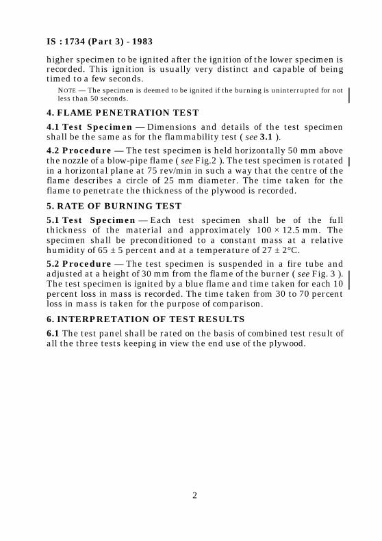
higher specimen to be ignited after the ignition of the lower specimen isrecorded. This ignition is usually very distinct and capable of beingtimed to a few seconds.
NOTE — The specimen is deemed to be ignited if the burning is uninterrupted for notless than 50 seconds.
4. FLAME PENETRATION TEST
4.1 Test Specimen — Dimensions and details of the test specimenshall be the same as for the flammability test ( see 3.1 ).
4.2 Procedure — The test specimen is held horizontally 50 mm abovethe nozzle of a blow-pipe flame ( see Fig.2 ). The test specimen is rotatedin a horizontal plane at 75 rev/min in such a way that the centre of theflame describes a circle of 25 mm diameter. The time taken for theflame to penetrate the thickness of the plywood is recorded.
5. RATE OF BURNING TEST
5.1 Test Specimen — Each test specimen shall be of the fullthickness of the material and approximately 100 × 12.5 mm. Thespecimen shall be preconditioned to a constant mass at a relativehumidity of 65 ± 5 percent and at a temperature of 27 ± 2°C.
5.2 Procedure — The test specimen is suspended in a fire tube andadjusted at a height of 30 mm from the flame of the burner ( see Fig. 3 ).The test specimen is ignited by a blue flame and time taken for each 10percent loss in mass is recorded. The time taken from 30 to 70 percentloss in mass is taken for the purpose of comparison.
6. INTERPRETATION OF TEST RESULTS
6.1 The test panel shall be rated on the basis of combined test result ofall the three tests keeping in view the end use of the plywood.

IS : 1734 (Part 3) - 1983
3
FIG. 1 SCHEMATIC DIAGRAM FOR FLAMMABILITY TEST

IS : 1734 (Part 3) - 1983
4
FIG. 2 SCHEMATIC DIAGRAM FOR FLAME PENETRATION TEST
FIG. 3 SCHEMATIC DIAGRAM FOR RATE OF BURNING TEST
IS : 1734 (Part 4) - 1983Edition 3.3
(2005-08)
© BIS 2005B U R E A U O F I N D I A N S T A N D A R D SMANAK BHAVAN, 9 BAHADUR SHAH ZAFAR MARG
NEW DELHI 110002
Indian StandardMETHODS OF TEST FOR PLYWOOD
PART 4 DETERMINATION OF GLUE SHEAR STRENGTH
( Second Revision )(Incorporating Amendment Nos. 1, 2 & 3)
UDC 674-419.32 : 668.3 : 620.176.2
1. SCOPE
1.1 This standard (Part 4) covers the method of test for the determina-tion of glue shear strength of plywood.
2. OBJECT
2.1 This test is intended to estimate the tenacity with which thebonding material holds the veneers together.
3. TEST SPECIMEN
3.1 At least six specimens for each pair of glue lines shall be cut fromthe panel from different locations.
3.2 The test pieces from 3-ply plywood shall be prepared by makingsaw cuts ( see Fig. 1 ). When the number of plies exceeds three,specimens shall be prepared to test all pairs of glue lines. Each testspecimen shall be cut so that the grain direction of the ply between theglue lines under test is perpendicular to the length of the testspecimen. Method of preparation of specimens for 7-ply plywood isshown in Fig. 1. The test specimens shall be prepared and saw cutsmade to allow the examination of each and every pair of glue lines inthe panel.

IS : 1734 (Part 4) - 1983
4
All dimensions in millimetres.
FIG. 1 TEST SPECIMEN FOR GLUE ADHESION TEST

IS : 1734 (Part 4) - 1983
3
4. PROCEDURE
4.1 Each test specimen shall be gripped symmetrically at two ends inthe jaws of a suitable testing machine, and shall be pulled apart. Thedistance between the notches on the test specimen and the end of thegripping jaws of the testing machine shall be between 10 mm and20 mm. The pull should be, as far as possible, in the centre line of thecentral veneer. The grain of the centre ply shall be perpendicular tothe direction of application of load. Measure the width of eachspecimen and distance between the notches to nearest 0.025 cm todetermine the shear area.
4.2 During the test, the load shall be applied to the test specimens asuniformly as possible, and so adjusted as to increase at a rate lying inthe range of 1 300 ± 500 N/min.
4.3 The maximum load at the time of complete failure of eachspecimen shall be recorded. Record shall also be made as to failurewhether in wood or in glue by visual examination of the area undershear. In case of wood failure the percentage wood failure shall also berecorded.
NOTE — In case of dispute, measurement of wood failure shall be done with the helpof a graphical mesh of area 25 × 25 mm printed on a transparent material placed onthe sheared surface, the wood failure may be objectively and quantitativelyestimated.
4.4 Clause deleted
5. REPORT
5.1 Failing load and percentage of wood failure of the tested specimensfor each pair of glue lines determined in accordance with 4 shall bestraight averaged and compare with values given in appropriateIndian Standard specification for plywood.
5.1.1 All the details shall be recorded under the following sub-heads:
a) Name of the manufacturer/source from whom the plywood isprocured,
b) Type and grade of plywood,
c) Construction of plywood in terms of the ratio of thickness ofindividual plies,
d) Species of individual plies,
e) Adhesive used,

IS : 1734 (Part 4) - 1983
4
f) End use of plywood,
g) Specimen No./Reference,
h) Area of cross section of bonding surface under shear,
j) Average load for each and every pair of glue lines, and
k) Average percentage of wood failure for each and every pair ofglue lines.

IS : 1734 (Part 5) - 1983
© BIS 1984B U R E A U O F I N D I A N S T A N D A R D SMANAK BHAVAN, 9 BAHADUR SHAH ZAFAR MARG
NEW DELHI 110002
Indian StandardMETHODS OF TEST FOR PLYWOOD
PART 5 TEST FOR ADHESION OF PLIES
( Second Revision )UDC 674-419.32 : 620.179.4
1. SCOPE
1.1 This standard (Part 5) covers test for adhesion of plies.
2. OBJECT
2.1 This test is intended to estimate the tenacity with which thebonding material holds the adjacent plies together.
3. TEST SPECIMEN
3.1 The test specimen shall be of the full thickness of the material andat least 250 × 250 mm. The specimen shall be preconditioned to acontant mass at a relative humidity of 65 ± 5 percent and at atemperature of 27 ± 2°C.
4. APPARATUS
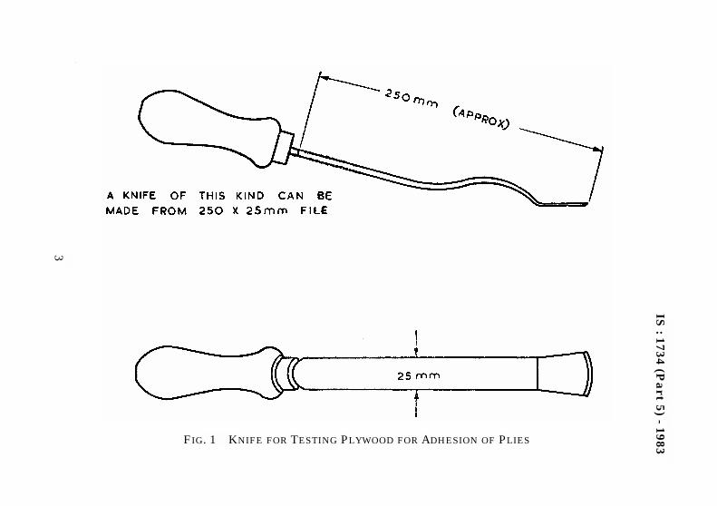
4.1 The type of knife required to be used in the test is given in Fig. 1. Itmay be made from a file. The cutting edge should be kept chiselsharp.
4.2 The test shall be carried out on a stout table to which is screwed awooden batten against which the edge of the test piece is placed asindicated in Fig. 2.
5. PROCEDURE
5.1 The knife is inserted with its cutting edge parallel to the grain of theouter veneer and worked into, or if possible, along a glue line and theveneer is prised upward. A hard and dense species of plywood requiresconsiderable force to effect entry and to prise the veneer. In a softtimber, the knife tends to follow an easy course through the wood in thiscase it is essential that the knife be firmly guided along the glue line.

IS : 1734 (Part 5) - 1983
2
5.2 Examples of cases when the bond just passes the requirements areindicated in Fig. 3 and this is judged by the relative amounts of woodfibre left on the core veneer, and the area prised off. The grading isassessed chiefly on the appearance of the break, but it is a concomitantrequirement that force shall be needed to effect separation.
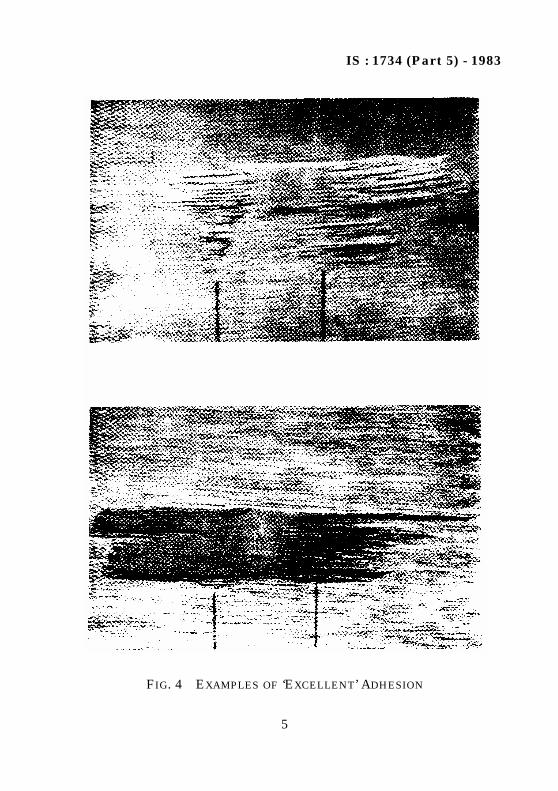
5.3 The bond is excellent, when it is difficult to find the glue line andimpossible to keep the tool within it for more than 3 to 6 mm withoutcutting into adjacent wood. On prising upwards, the veneer usuallybreaks off over a width only slightly greater than that of the tool.Examples of excellent bond are illustrated in Fig. 4.
5.4 The bond is poor, when the knife meets little opposition in the glueline and the prise results in the easy removal of almost all the veneersfrom one side of the test piece. The separated veneers are usually almostfree from adherent fibre. Examples of poor bond are illustrated in Fig. 5.
NOTE — Interpretation of knife test results requires experience which can beobtained with practice and a little help.
6. REPORTING OF TEST RESULTS
6.1 The results shall be reported as ‘minimum pass’, ‘excellent’, ‘poor’( see Fig. 3, 4 and 5 ). All the details shall be recorded under thefollowing sub-heads:
a) Name of the manufacturer/source from whom the plywood isprocured,
b) Type and grade of plywood,c) Construction of plywood in terms of the ratio of thickness of
individual plies,d) Species of individual plies,e) Adhesive used,f) End use of plywood,g) Specimen No./reference, andh) Result — minimum pass/excellent/poor.
IS:1734
(Pa
rt5)
-1983
3
.‘
FIG. 1 KNIFE FOR TESTING PLYWOOD FOR ADHESION OF PLIES

IS : 1734 (Part 5) - 1983
4
FIG. 2 METHOD OF TESTING FOR ADHESION
FIG. 3 EXAMPLE OF ‘MINIMUM PASS’ STANDARD
IS : 1734 (Part 5) - 1983
5
FIG. 4 EXAMPLES OF ‘EXCELLENT’ ADHESION

IS : 1734 (Part 5) - 1983
6
FIG. 5 EXAMPLES OF ‘POOR’ ADHESION

IS : 1734 (Part 6) - 1983Edition 3.2
(2005-01)
© BIS 2005B U R E A U O F I N D I A N S T A N D A R D SMANAK BHAVAN, 9 BAHADUR SHAH ZAFAR MARG
NEW DELHI 110002
Indian StandardMETHODS OF TEST FOR PLYWOOD
PART 6 DETERMINATION OF WATER RESISTANCE
( Second Revision )(Incorporating Amendment Nos. 1 & 2)
UDC 674-419.32 : 620.193.19
1. SCOPE
1.1 This standard (Part 6) covers the methods of test for the determi-nation of water resistance of plywood.
2. OBJECT
2.1 This test is primarily intended to determine the acceptability orotherwise of plywood panel where it is subjected to alternate dryingand wetting or high humidity.
3. SPECIMEN
3.1 Specimen for Glue Shear Strength
Dimensions and details of the test specimen shall be same as given in3 of IS : 1734 (Part 4)-1983
3.2 Specimen for Adhesion of Plies
From each board at least 4 test specimens each approximately250 mm × 250 mm shall be cut from different positions in the boardsuch that the grain of the face veneer is parallel to the length of thepiece.
4. PROCEDURE
4.1 Clause deleted.
4.2 For the boiling water immersion tests, these specimens shall bekept submerged in a pan of boiling water for a period as specified forthe particular grade of the plywood, for example, 72 hours for BWP

IS : 1734 (Part 6) - 1983
2
and 8 hours for BWR. However, for moisture resistance test(applicable to MR grade of plywood), the specimen shall be keptimmersed in warm water at 60 ± 2°C for a period of 3 hours. These testpieces shall then be removed from the water and cooled down to roomtemperature by plunging them in cold water. These wet pieces whilestill in wet condition shall be tested for ‘glue shear strength’ and/or‘adhesion of plies’ according to methods laid down in IS : 1734(Part 4)-1983* and IS : 1734 (Part 5)-1983† respectively.
5. REPORT
5.1 All the details shall be recorded and reported as required inIS : 1734 (Part 4)-1983* and/or IS : 1734 (Part 5)-1983†.
5.2 Visual examination shall also be made before carrying out ‘glueshear strength’ and/or ‘adhesion of plies’ for any delamination, blisterformation, etc.
5.3 The plywood when tested as above shall comply with the standardspecified for its end use.
*Methods of test for plywood: Part 4 Determination of glue shear strength ( secondrevision ).
†Methods of test for plywood: Part 5 Test for adhesion of plies ( second revision ).

IS : 1734 (Part 7) - 1983Edition 3.1
(2004-12)
© BIS 2005B U R E A U O F I N D I A N S T A N D A R D SMANAK BHAVAN, 9 BAHADUR SHAH ZAFAR MARG
NEW DELHI 110002
Indian StandardMETHODS OF TEST FOR PLYWOOD
PART 7 MYCOLOGICAL TEST
( Second Revision )(Incorporating Amendment No. 1)
UDC 674-419.32 : 620.193.811. SCOPE
1.1 This standard (Part 7) covers the mycological test for plywood.
2. OBJECT
2.1 This test is intended to evaluate the resistance of glue line(adhesive) to attack by micro-organisms. It is not a test of thedurability of the species from which the plywood is manufactured.
3. TEST SPECIMEN
3.1 Dimensions and details of the test specimen shall be the same asrequired under 3 of IS : 1734 (Part 4)-1983*.
4. PROCEDURE
4.1 A flat rectangular dish of enamelled iron, glass or porcelain (suchas a photographic developing dish), of a minimum depth of 50 mm,shall be filled to a depth of about 25 mm with a layer of sawdustobtained from the sapwood of a perishable timber, like semul ( Bombaxceiba ) in its natural condition. The sawdust shall have previously beenmoistened with water containing 15 g of sucrose (normally sugar maybe used; but if unavailable, 30 g of commercial malt extract may besubstituted) to a litre of water so that it is saturated with moisture,
*Methods of test for plywood: Part 4 Determination of glue shear strength ( secondrevision ).

IS : 1734 (Part 7) - 1983
2
but not so wet that free water is squeezed out of it by hand pressure.To attain this condition with dry sawdust, it is usually necessary toadd three times its mass of water.
4.2 The saw dust shall then be charged with the spores of thecommonly occurring mould fungi like Aspergillus niger (Black mould),Aspergillus sp. (Yellow mould), Pencillium sp. (Green or blue mould)and loosely compacted. The test specimens shall be pressed down intoit so that their upper surfaces are in level with the top of the sawdustlayer.
4.3 The dish shall then be covered with a sheet of glass and the edgesof the dish sealed against the glass with modelling clay or a similarsuitable material so that the atmosphere round the test specimensshall remain saturated with water vapour.
4.4 The dish and the contents shall be maintained at a temperature of27 ± 2°C for a period of three weeks, after which the test pieces shall beremoved, washed in water at room temperature, and whilst still water-soaked, shall be tested at room temperature for glue shear strength aslaid down in IS : 1734 (Part 4)-1983* for compliance to the minimumrequirement laid down in the relevant Indian Standard specificationfor plywood.
5. REPORT
5.1 All the details shall be recorded and reported as required inIS : 1734 (Part 4)-1983*.
*Methods of test for plywood: Part 4 Determination of glue shear strength ( secondrevision ).

IS : 1734 (Part 8) - 1983
© BIS 1984B U R E A U O F I N D I A N S T A N D A R D SMANAK BHAVAN, 9 BAHADUR SHAH ZAFAR MARG
NEW DELHI 110002
Indian StandardMETHODS OF TEST FOR PLYWOOD
PART 8 DETERMINATION OF pH VALUE
( Second Revision )UDC 674-419.32 : 543-257.1
1. SCOPE
1.1 This standard (Part 8) covers the method of test for thedetermination of pH value.
2. OBJECT
2.1 This test is intended to evaluate the resistance of plywood todeterioration upon normal ageing as the flexural, impact and shearstrength values of plywood may be affected by the pH value of the glueused in the panels.
3. PREPARATION OF SPECIMEN AND TEST PROCEDURE
3.1 A sufficient portion of the wood adjacent to the glue line of theplywood panel is ground in a mill to pass 425-µm IS Sieve. One gram ofthe powder, accurately weighed, shall be placed in a clean vial or a smallheat resistant flask and 5 ml of freshly boiled, cooled distilled watershall be added and thoroughly stirred. The glass container shall be keptstoppered throughout the test except when pH determinations are beingmade. The mixture shall be allowed to stand for 72 hours at 27 ± 2°Cafter which time the mixture shall be stirred and the pH valuedetermined by a suitable pH meter. The determination of pH value shallbe repeated at intervals of 24 hours until difference between theconsecutive readings is not more than 0.05 pH units; the last readingtaken shall be regarded as the equilibrium pH value for the specimen.
NOTE — Alternatively pH be measured by MpH value as wood exerts bufferingaction. This may be done by adding the wood powder to various solutions containingfree hydrogen ions and measuring the pH; where there is no pH change it is thecorrect value of the wood. One gram of wood adjacent to the glue line is ground to finesawdust and suspended in 5 ml of hydrochloric acid of pH 4. The same is done to theveneers where the pH of the plywood is lower than that of the veneers.

IS : 1734 (Part 8) - 1983
2
4 REPORT
4.1 The pH value determined shall be reported. All the details shall berecorded under the following sub-heads:
a) Name of the manufacturer/source from whom the plywood isprocured,
b) Type and grade of plywood,c) Construction of plywood in terms of the ratio of thickness of
individual plies,d) Species of individual plies,e) Adhesive used,f) End use of plywood,g) Specimen No./reference, andh) pH value.

IS : 1734 (Part 9) - 1983
© BIS 1984B U R E A U O F I N D I A N S T A N D A R D SMANAK BHAVAN, 9 BAHADUR SHAH ZAFAR MARG
NEW DELHI 110002
Indian StandardMETHODS OF TEST FOR PLYWOOD
PART 9 DETERMINATION OF TENSILE STRENGTH
( Second Revision )UDC 674-419.32 : 620.172
1. SCOPE
1.1 This standard (Part 9) covers the method of test for the determina-tion of tensile strength.
2. OBJECT
2.1 This test is intended to evaluate the ultimate tensile strength ofplywood.
3. TEST SPECIMEN
3.1 For the tensile strength test, specimens of Types A, B, C, D or E asillustrated in Fig. 1 are particularly recommended, but specimens ofany other types that give equally satisfactory results may be used. Thegrain direction of the face plies shall be parallel or perpendicular to thelength of the test specimen. The specimen shall be preconditioned to aconstant mass at a relative humidity of 65 ± 5 percent and at atemperature of 27 ± 2°C.
3.2 When the evaluation of elastic properties as well as ultimatetensile strength is required, the size and shape of the test specimenshall be selected from Types A, B and C. The basis for selection shallbe the grain angle and the thickness of the material. If the grain of theindividual plies makes an angle of other than 0° or 90°, with the lengthof the specimen, Type C shall be used regardless of the thickness of thematerial. For grain angles individual ply of 0° or 90°, Type A shall beused for material over 6 mm in thickness and Type B for material6 mm or less in thickness. The specimen shall have a thickness equalto that of the material and the thickness and the width of eachspecimen at the critical section shall also be measured to an accuracyof not less than ± 0.3 percent.

IS : 1734 (Part 9) - 1983
2
3.3 When the evaluation of the ultimate tensile strength only isrequired specimens of Types D and E may be used. Type D is designedfor specimens greater than 6 mm in thickness, and Type E forspecimens 6 mm or less in thickness. Measurements of each specimenshall be made to an accuracy of not less than ± 0.3 percent.
3.4 The test specimens shall be properly shaped, using a template inconjunction with a vertical-spindle woodworking shaper or any othermethod that will give equally satisfactory results.
4. PROCEDURE
4.1 The load shall be applied continuously throughout the test at arate of traverse of the movable head of 1 mm/min. The specimen shallbe held in wedge-type self-tightening and self-aligning grips.
4.2 Data for load-deformation curves may be taken to determine themodulus of elasticity and the tensile stress at proportional limit.Increments of load shall be chosen so that not less than 12 andpreferably 15 or more readings of load and deformation are taken tothe proportional limit. The deformation measuring apparatus shall beattached at the central portion of the length of the specimen at thecentral portion of constant cross section. Deformation readings shall betaken to the nearest 0.002 mm.
5. REPORT
5.1 Maximum tensile stress, the modulus of elasticity and the tensilestress at proportional limit, if required, shall be reported. Themoisture content of the specimen and its temperature at the time oftest shall be recorded.
5.1.1 The details shall be recorded under the following sub-heads:
a) Name of the manufacturer/source from whom the plywood isprocured;
b) Type and grade of plywood;c) Construction of plywood in terms of the ratio of thickness of
individual plies;d) Species of individual plies;e) Adhesive used;f) End use of plywood;g) Specimen No./reference and name of test;h) Area of cross section;

IS : 1734 (Part 9) - 1983
3
5.1.2 In addition, the following properties may also be recorded:
j) Gauge length;k) Rate of loading;m) Maximum load;n)Moisture content, percent; andp)Room temperature.
a) Load at proportional limit;b) Deformation (elongation) at proportional limit;c) Maximum tensile stress;d) Modulus of elasticity;e) Tensile stress at proportional limit; andf) Density at the above moisture content (if determined otherwise).
All dimensions in millimetres.
FIG. 1 DETAILS OF PLYWOOD TENSILE TEST SPECIMENS — Contd

IS : 1734 (Part 9) - 1983
4
All dimensions in millimetres.
FIG. 1 DETAILS OF PLYWOOD TENSILE TEST SPECIMENS
IS : 1734 (Part 10) - 1983
© BIS 1984B U R E A U O F I N D I A N S T A N D A R D SMANAK BHAVAN, 9 BAHADUR SHAH ZAFAR MARG
NEW DELHI 110002
Indian StandardMETHODS OF TEST FOR PLYWOOD
PART 10 DETERMINATION OF COMPRESSIVE STRENGTH
( Second Revision )UDC 674-419.32 : 620.173
1. SCOPE
1.1 This standard (Part 10) covers the method of test for the determi-nation of compressive strength.
2. OBJECT
2.1 This test is intended to evaluate the compressive strength atelastic limit as well as maximum compressive strength of plywood.
3. TEST SPECIMEN
3.1 The test specimen shall be rectangular. The thickness, width andlength of each specimen shall be measured to an accuracy of not lessthan ± 0.3 percent. The grain direction of the face plies may be parallelor perpendicular to the length of the test specimen. The specimen shallbe conditioned to a constant mass at a relative humidity of 65 ± 5 per-cent and at a temperature of 27 ± 2°C.
3.2 When tests to evaluate both elastic and maximum compressivestrength properties are required ( see 4.1.1 ), the size of the specimenshall be as follows:
a) For material over 6 mm in thickness, the specimen shall have athickness equal to the material and the width shall be aminimum of 25 mm but not less than the thickness. The lengthshall be not greater than seven times the least cross-sectionaldimension.
b) For material 6 mm or less in thickness, the specimen shall have athickness equal to that of the material and shall be 25 mm wide.The length shall be 10 cm. Such specimen shall be supportedlaterally throughout the test.

IS : 1734 (Part 10) - 1983
2
3.3 When tests to evaluate maximum compressive strength alone arerequired ( see 4.1.2 ) plywood specimens of 10 cm length shall be gluedtogether such that the total thickness is equal to the width and liesbetween 20 mm and 40 mm.
3.4 Care shall be taken in preparing the test specimen to make the endsurfaces smooth and parallel to each other and at right angles to thelength.
4. TYPES OF TEST
4.1 The two types of compressive strength tests are as follows:a) Method A, providing lateral support of the specimen when
needed. This shall be used when tests to evaluate both elastic andmaximum compressive strength properties are required; and
b) Method B may be used when tests to evaluate maximum com-pressive strength only are required.
4.1.1 Method A — for Evaluation of Both Maximum CompressiveStrength and Elastic Properties
4.1.1.1 Test specimens 6 mm or less in thickness intended for use inobtaining load deformation data shall be supported laterally to preventbuckling during the test, but undue pressure shall not be exertedagainst the sides of the specimen. This support shall not measurablyrestrain the normal compressive deformation under load.
4.1.1.2 Procedure — The load shall be applied through a sphericalbearing block preferably of the suspended, self-aligning type. The loadshall be applied with a continuous motion of the movable head to maxi-mum load at a rate of 0.003 cm/cm length of the specimen per minutewithin a permissible variation of ± 25 percent. Data for load-deforma-tion curves may be taken to determine the modulus of elasticity andthe proportional limit. Increments of load shall be chosen so that notless than 12, but preferably 15 or more, readings of load anddeformation are taken to the proportional limit. The deformation shallbe read to the nearest 0.002 mm. Compressometers shall be attachedover the central portion of the length of the specimen and the points ofattachment shall be not less than 18 mm from the specimen ends.
4.1.2 Method B — for Evaluation of Maximum Compressive StrengthOnly — Specimens shall be held together by suitable supports, and theload shall be applied through a spherical bearing block of self-aligningtype with a continuous rate of cross-head movement of 0.5 mm perminute till a failure is indicated. Maximum crushing stress shall becalculated and reported with reference to the grain of the face veneer.

IS : 1734 (Part 10) - 1983
3
5. REPORT
5.1 Maximum crushing stress, modulus of elasticity and crushingstress at elastic limit, if required, shall be reported with reference tothe grain of the face veneer. Moisture content and temperature at thetime of test shall also be reported.
5.1.1 The details shall be recorded under the following sub-heads:
5.1.2 In addition, the following properties may also be recorded:
a) Name of the manufacturer/source from whom the plywood isprocured;
b) Type and grade of plywood;c) Construction of plywood in terms of the ratio of thickness of
individual plies;d) Species of individual plies;e) Adhesive used;f) End use of plywood;g) Specimen No./reference;h) Area of cross section;j) Gauge length;
k) Rate of loading;m) Maximum load;n)Moisture content, percent; andp)Room temperature.
a) Load at proportional limit;b) Deformation (elongation) at proportional limit;c) Maximum compressive stress;d) Modulus of elasticity;e) Compressive stress at proportional limit; andf) Density at the above moisture content, if determined otherwise.

IS : 1734 (Part 11) - 1983
© BIS 1984B U R E A U O F I N D I A N S T A N D A R D SMANAK BHAVAN, 9 BAHADUR SHAH ZAFAR MARG
NEW DELHI 110002
Indian StandardMETHODS OF TEST FOR PLYWOOD
PART 11 DETERMINATION OF STATIC BENDING STRENGTH
( Second Revision )UDC 674-419.32 : 620.174
1. SCOPE
1.1 This standard (Part 11) covers the method of test for the determi-nation of static bending strength of plywood as determined by centralloading method and two-point load method.
2. CENTRAL LOADING METHOD
2.1 Object — This test is intended to determine the strength(modulus of rupture), stiffness (modulus of elasticity × moment ofinertia) and other properties related to flexural stress and is applicableto material that is uniform with respect to elastic and strengthproperties. Total deflection and modulus of elasticity computed from it,include a relatively constant component attributable to sheardeformation. It is well suited to investigations of many variables thatinfluence properties uniformly throughout the panel in controlledstudies and to test small, defect-free specimens cut from large panels.
2.2 Test Specimen — The test specimen for plywood shall be rectan-gular. The depth of the specimen shall be equal to the thickness ofmaterial and the width shall be 2.5 cm for depths less than 6 mm and 5cm for greater depths. When the grain direction of the face plies isparallel to the span, the length of the specimen shall be 48 times thedepth plus 5 cm; when the grain direction of the face is perpendicularto the span, the length of the specimen shall be 24 times the depth plus5 cm. The specimen shall be preconditioned to a constant mass at arelative humidity of 65 ± 5 percent and at a temperature of 27 ± 2°C.The width and depth of each specimen shall be measured to anaccuracy of not less than ± 0.3 percent.
IS : 1734 (Part 11) - 1983
2
2.3 Procedure
2.3.1 Span — The span shall be 48 times the nominal depth when thegrain direction of the face plies of the test specimen is parallel to thespan and 24 times the nominal depth when the grain direction of theface plies is perpendicular to the span.
2.3.2 The load shall be applied through an appropriate loading blockfor centre loading with a continuous motion of the movable headthroughout the test till a failure is indicated. The rate of application ofload shall be such that the unit rate of fibre strain is equal to 0.001 5cm/cm of outer fibre length per minute within a permissible variationof ± 25 percent. The rate of motion of moving head may be calculatedas follows:
where
2.4 Report — Data for load deflection curves may be taken to deter-mine the various characteristics using the formulae given below.Deflection readings shall be recorded to the nearest 0.02 mm.Increments of load shall be so chosen that not less than 12 andpreferably 15 or more readings of load and deflection are taken to theproportional limit. The moisture content of the specimen and thetemperature at the time of test shall be recorded:
N = rate of motion of moving head in cm/min,z = unit rate of fibre strain in cm/cm of outer fibre length per
minute = 0.001 5,L = span in cm, andd = depth of beam in cm.
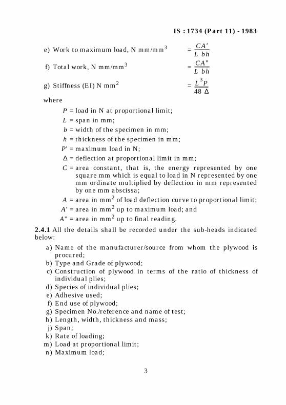
a) Fibre stress at proportional limit, N/mm2 =
b) Modulus of rupture, N/mm2 =
c) Modulus of elasticity, N/mm2 =
d) Work to proportional limit, N mm/mm3 =
N zL2
6d----------=
3PL
2 bh2---------------
3 P′L
2 bh2---------------
PL3
4 bh3∆-------------------
CAL bh------------- P ∆
2 Lbh-----------------=
IS : 1734 (Part 11) - 1983
3
where
2.4.1 All the details shall be recorded under the sub-heads indicatedbelow:
e) Work to maximum load, N mm/mm3 =
f) Total work, N mm/mm3 =
g) Stiffness (EI) N mm2 =
P = load in N at proportional limit;L = span in mm;b = width of the specimen in mm;h = thickness of the specimen in mm;P' = maximum load in N;∆ = deflection at proportional limit in mm;C = area constant, that is, the energy represented by one
square mm which is equal to load in N represented by onemm ordinate multiplied by deflection in mm representedby one mm abscissa;
A = area in mm2 of load deflection curve to proportional limit;A' = area in mm2 up to maximum load; andA'' = area in mm2 up to final reading.
a) Name of the manufacturer/source from whom the plywood isprocured;
b) Type and Grade of plywood;c) Construction of plywood in terms of the ratio of thickness of
individual plies;d) Species of individual plies;e) Adhesive used;f) End use of plywood;g) Specimen No./reference and name of test;h) Length, width, thickness and mass;j) Span;
k) Rate of loading;m) Load at proportional limit;n) Maximum load;
CA′L bh-------------
CA″L bh-------------
L3P48 ∆------------

IS : 1734 (Part 11) - 1983
4
3. TWO-POINT LOADING
3.1 Object — This method, like method described in 2, is suited to theinvestigations of factors that influence strength and elastic propertiesuniformly throughout the panel in controlled studies and testing smallclear and defect-free control specimens cut from large panels. This maybe used to determine the effects of finger joints, veneer joints and gapsand other features which can be placed entirely between the loadpoints and whose effects can be projected readily to full panel width.Deflection and modulus of elasticity obtained from this method arerelated to flexural stress only and do not contain a shear component.Significant errors in modulus of rupture can occur where nominalmoment is used.3.2 Test Specimen — The test specimen shall be rectangular incross-section. The length shall exceed by 5 cm the span ( see 3.2.2 ) onwhich it is to be tested. The depth of the specimen shall be equal to thethickness of the plywood, and the width shall be 25 mm for thicknessless than 6 mm and 50 mm for thickness 6 mm and above. Thespecimen shall be conditioned to a constant mass at a relativehumidity of 65 ± 5 percent and at a temperature of 27 ± 2°C. Thisspecimen thickness shall be measured at mid-span at two points neareach edge and the average recorded. Measurement shall be taken tothe nearest 0.02 mm or 0.3 percent. Width shall be measured atmid-span to the nearest 0.3 percent.3.2.1 When needed for interpretation of test results thickness of eachply shall be measured nearest to 0.02 mm at mid-span at each edgeand the average shall be recorded.3.2.2 Span — Span-depth ratio has relatively little influence on theresults of tests using two-point loading and the method measuringdeformation described for it in this standard. However, it is importantthat the distance between load point and adjacent support be sufficientto prevent rolling shear failures.
p) Deformation at proportional limit;q) Flexural stress at proportional limit;r) Modulus of rupture;s) Modulus of elasticity;t) Work to proportional limit;u) Work to maximum load;v) Total work;w) Moisture content, percent; andy) Density at the moisture content given in (w), if determined
otherwise.

IS : 1734 (Part 11) - 1983
5
3.2.2.1 Specimen tested for stiffness only shall have a span at least 48times the nominal thickness if face grain is parallel to span and 24times the nominal thickness if face grain is perpendicular to span.
3.2.2.2 It is recommended that two-point loading tests to failure bemade on a span at least equal to the spacing between load points plus48 times the specimen thickness or 24 times the specimen thicknessfor face grain parallel or perpendicular respectively. Material havinghigh rolling shear strength or having all its grain parallel to span mayuse closer spacing between loads and supports.
3.3 Procedure — The ends of a small flexure specimen shall besupported on special reaction bearings which, in turn, rest on the tableof a conventional testing machine. Two equal loads shall be applied tothe specimen equidistant from the supports by cylindrical surfaceshaving a radius of curvature of at least one-and-a-half times thespecimen thickness wherever it may contact the specimen. The axes ofthese surfaces shall remain parallel and at least one of them shall befree to turn about its axis or be loaded through rollers to prevent theapplication of friction forces to the surfaces of the specimen.Construction of a satisfactory loading head is shown in Fig. 1. Thepivot point which equalizes the two loads shall be located near theoriginal neutral axis of the specimen, thus subjecting the middle halfof the specimen to conditions of nearly pure movement.
Load point shall be spaced sufficiently to provide a deflection whichcan be adequately measured. A spacing of at least 24 and 12 timesspecimen thickness is recommended for specimen with face grainparallel and perpendicular to span respectively. The sum of two loadsshall be measured to an accuracy of at least 1 percent of indicatedvalue or 0.4 percent of full scale whichever is larger.
3.4 Speed of Test — Load shall be applied at a continuous rate ofmotion of the load points with respect to the supports within apermissible range of 25 percent of the rate determined by the followingformula:
where
N = rate of motion in cm/min,Z = unit rate of fibre strain in (cm/cm)/min,a = distance from support to adjacent load in cm,d = depth of beam in cm, andL = span in cm.
N Za3d------- 3 L 4a–( )=

IS : 1734 (Part 11) - 1983
6
3.5 Measurement and Deflection — Deflection on mid-span withrespect to a line between two points equidistant from mid-span andjust inside the two loading points shall be measured to an accuracy ofat least 1.5 percent of total deflection, if tested for stiffness only, or 1.5percent of deflection at approximate proportional limit. All the threepoints shall lie on the longitudinal axis of the specimen. Deflectionshall be measured with a dial gauge or transducer. A typicalequipment of the transducer type is illustrated in Fig. 1.
A dial gauge could replace the transducer for manual reading. Ifindividual gauge readings are taken, at least 12 and preferably 15 ormore load and deflection readings shall be taken below approximateproportional limit or for determining specimen stiffness.
3.6 Report and Calculation — Modulus of rupture and stiffnessshall be calculated by the following formula:
Notations other than those given below shall have the samemeaning as given in 2.4.
where
where
Modulus of rupture (M of R) =
=
L1 = span between load points in mm,
c = distance from neutral axis to extreme fibre in mm,
I = moment of inertia in mm4, and
P = maximum load in N.
Modulus of elasticity, N/mm2 =
Stiffness (EI) =
L2 = span between deflection measurement points in mm, andS = deflection of mid-span relative to ends of span L2 in mm.
3P L L1–( )
2 bh2---------------------------------------, or
P L L1–( ) c
4I-----------------------------------------
3P L L1–( ) L22
8 bh3 ∆----------------------------------------------------
L L1–( ) L22
32------------------------------------------ P
S----×

IS:1734
(Pa
rt11)
-1983
7
FIG. 1 TWO-POINT LOAD TEST FOR SMALL PLYWOOD FLEXURE SPECIMENS
IS : 1734 (Part 12) - 1983
© BIS 1984B U R E A U O F I N D I A N S T A N D A R D SMANAK BHAVAN, 9 BAHADUR SHAH ZAFAR MARG
NEW DELHI 110002
Indian StandardMETHODS OF TEST FOR PLYWOOD
PART 12 DETERMINATION OF SCARF JOINT STRENGTH
( Second Revision )UDC 674-419.32 : 674.028.11 : 620.17
1. SCOPE
1.1 This standard (Part 12) covers the method of test for thedetermination of scarf joint strength of plywood.
2. OBJECT
2.1 The two tests, namely, mandrel test and tensile strength test, areprescribed to evaluate the strength of a scarf joint.
3. MANDREL TEST (BENDING TEST FOR SCARF JOINT FOR PLYWOOD UP TO 3 mm IN THICKNESS)
3.1 Test Specimen — Each test specimen shall be approximately38 × 2.5 cm and shall be cut in a direction at right angles to the line ofthe scarf with the scarf approximately in the centre of the specimen.The test specimen shall be preconditioned to a constant mass at arelative humidity of 65 ± 5 percent and at a temperature of 27 ± 2°C.
3.2 Procedure — Test specimens are bent round a mandrel of adiameter 200 times the thickness of plywood, in such a way that thescarf is within the fully bent position and then examined for signs ofdelamination or damage at the scarf joint.
Test specimens are then broken on a mandrel of smaller diameterand distribution of adherent fibres examined and expressed as apercentage of the whole area. The test shall be repeated with aspecimen of the same dimension but without the scarf joint.
NOTE 1 — A number of mandrels of progressively smaller diameters are to be triedtill the specimen breaks.
NOTE 2 — For aircraft plywood the mandrel test is employed as a quality control test.In this case the diameter of the mandrel is only 100 times that of the thickness of

IS : 1734 (Part 12) - 1983
2
plywood and the test is employed up to 5 mm thickness. Breakages or fractures ofmore than 20 percent of all the specimens tested shall be considered as the cause forthe rejection of the whole lot.
3.3 Report — The percentage of wood failure for each test specimenshall be reported.
3.3.1 The ratio of percentages of wood failure in the case of two types oftest specimens, namely, one with scarf joint and the other withoutscarf joint shall also be reported.
4. TENSILE STRENGTH TEST OF THE SCARF JOINT (ALSO KNOWN AS LONGITUDINAL TEST) (FOR PLYWOOD ABOVE 3 mm IN THICKNESS)
4.1 Test Specimen — Dimensions and details of the test specimensshall be the same as for mandrel test ( see 3.1 ) except that the scarfjoint is exactly centrally disposed in a direction at right angles to thelength of the test specimen.
4.2 Procedure — The test specimens shall be tested in the samemanner as for the determination of tensile strength of plywood[ see IS : 1734 (Part 9)-1983* ]. The test shall be repeated with aspecimen of the same dimensions but without the scarf joint.
4.3 Report — The load taken by both the test specimens shall bereported separately together with the ratio of the loads of the piecewith the scarf joint to that without the scarf joint. The location of thefailure and the percentage of wood failure on the joints shall also bereported. All the details shall be recorded under the following sub-heads:
*Methods of test for plywood : Part 9 Determination of tensile strength ( secondrevision ).
a) Name of the manufacturer/source from whom the plywood isprocured;
b) Type and grade of plywood;c) Construction of plywood in terms of the ratio of thickness of
individual plies;d) Species of individual plies;e) Adhesive used;f ) End use of plywood;g) Specimen No./reference;h) Thickness of specimen;

IS : 1734 (Part 12) - 1983
3
j) Diameter of standard mandrel;k) Visual examination of the specimen when bent round the
standard mandrel;m) Diameter of the mandrel on which the specimen breaks;n) Percentage of wood failure:
1) with scarf joint,2) without scarf joint, and3) ratio of above; and
p) Load taken by the specimen:1) with scarf joint,2) without scarf joint, and3) ratio of above; and
q) Location of failure.

IS : 1734 (Part 13) - 1983
© BIS 1984B U R E A U O F I N D I A N S T A N D A R D SMANAK BHAVAN, 9 BAHADUR SHAH ZAFAR MARG
NEW DELHI 110002
Indian StandardMETHODS OF TEST FOR PLYWOOD
PART 13 DETERMINATION OF PANEL SHEAR STRENGTH
( Second Revision )UDC 674-419.32 : 620.176.2
1. SCOPE
1.1 This standard (Part 13) covers the method of test for the determi-nation of panel shear strength.
2. OBJECT
2.1 This test is intended to evaluate the panel shear strength of theplywood.
3. METHOD A
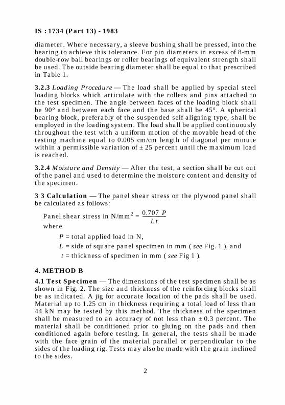
3.1 Test Specimen — The grain direction of the individual plies shallbe at an angle of 0° or 90° with the edges of the panel. The dimensionsof the test specimen ( see Fig. 1 ) shall conform to the sizes prescribedin Table 1 for the respective thickness of plywood used. The size andthickness of reinforcing wooden blocks shall also conform to the valuesprescribed in Table 1. The thickness, width and length of eachspecimen shall be measured to an accuracy of not less than ± 0.3percent. The specimen shall be preconditioned to a constant mass at arelative humidity of 65 ± 5 percent and at a temperature of 27 ± 2°C.
3.2 Procedure
3.2.1 Size and Location of Pins — The sizes and location of the pinsused to load the panel shall be as prescribed in Table 1. Care shall betaken in drilling the holes to make the surfaces smooth and the axesperpendicular to the plane of the plywood.
3.2.2 Pins and Rollers — The pins shall be of a quality equal to that ofsteel having a yield point of approximately 686 N/mm2 and anultimate tensile strength of approximately 862 N/mm2. The rollersshall be the ball or roller bearing type of standard bearing sizes withan inside diameter approximately 0.025 mm larger than the pin
IS : 1734 (Part 13) - 1983
2
diameter. Where necessary, a sleeve bushing shall be pressed, into thebearing to achieve this tolerance. For pin diameters in excess of 8-mmdouble-row ball bearings or roller bearings of equivalent strength shallbe used. The outside bearing diameter shall be equal to that prescribedin Table 1.
3.2.3 Loading Procedure — The load shall be applied by special steelloading blocks which articulate with the rollers and pins attached tothe test specimen. The angle between faces of the loading block shallbe 90° and between each face and the base shall be 45°. A sphericalbearing block, preferably of the suspended self-aligning type, shall beemployed in the loading system. The load shall be applied continuouslythroughout the test with a uniform motion of the movable head of thetesting machine equal to 0.005 cm/cm length of diagonal per minutewithin a permissible variation of ± 25 percent until the maximum loadis reached.
3.2.4 Moisture and Density — After the test, a section shall be cut outof the panel and used to determine the moisture content and density ofthe specimen.
3 3 Calculation — The panel shear stress on the plywood panel shallbe calculated as follows:
Panel shear stress in N/mm2 =where
4. METHOD B
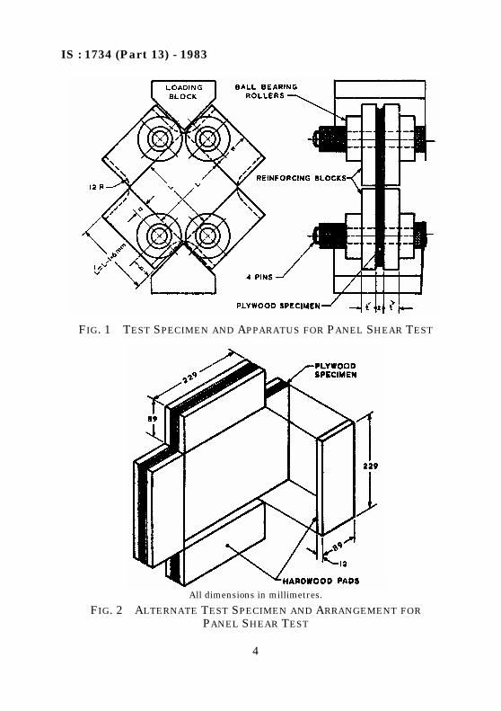
4.1 Test Specimen — The dimensions of the test specimen shall be asshown in Fig. 2. The size and thickness of the reinforcing blocks shallbe as indicated. A jig for accurate location of the pads shall be used.Material up to 1.25 cm in thickness requiring a total load of less than44 kN may be tested by this method. The thickness of the specimenshall be measured to an accuracy of not less than ± 0.3 percent. Thematerial shall be conditioned prior to gluing on the pads and thenconditioned again before testing. In general, the tests shall be madewith the face grain of the material parallel or perpendicular to thesides of the loading rig. Tests may also be made with the grain inclinedto the sides.
P = total applied load in N,L = side of square panel specimen in mm ( see Fig. 1 ), andt = thickness of specimen in mm ( see Fig 1 ).
0.707 PLt
---------------------

IS : 1734 (Part 13) - 1983
3
4.2 Procedure — The load shall be applied by compression across adiagonal. The movement of the cross-head of the testing machine shallbe continuous at the rate of 2.0 mm/min ± 25 percent. A suitable testapparatus is shown in Fig. 1. Shear stress calculations, moisturecontent and density determinations shall be made as described inMethod A (3).
4.3 Report — The panel shear stress, the moisture content anddensity of each specimen shall be reported. All the details shall berecorded under the following sub-heads:
a) Name of the manufacturer/source from whom the plywood isprocured;
b) Type and grade of plywood;c) Construction of plywood in terms of the ratio of the thickness of
individual plies;d) Species of individual plies;e) Adhesive used;f ) End use of plywood;g) Specimen No./reference;h) Size of the specimen:
1) Thickness, and
2) Average side of the square panel;j) Rate of loading;
k) Maximum load;m) Panel shear stress;n) Moisture content, percent; andp) Density.
IS : 1734 (Part 13) - 1983
4
FIG. 1 TEST SPECIMEN AND APPARATUS FOR PANEL SHEAR TEST
All dimensions in millimetres.
FIG. 2 ALTERNATE TEST SPECIMEN AND ARRANGEMENT FORPANEL SHEAR TEST

IS:1734
(Pa
rt13)
-1983
5
TABLE 1 DIMENSIONS OF PLYWOOD PANEL SHEAR SPECIMENS
( Clauses 3.1, 3.2.1, and 3.2.2, and Fig. 1 )
All dimensions in millimetres.
PLYWOOD THICKNESS
MAXIMUM ALLOWABLE PANEL SIZE (BETWEEN BLOCKS)
MINIMUM BLOCKWIDTH
W
MINIMUM BLOCK
THICKNESSt
DIAMETEROF PINS
d
DIAMETEROF PINHOLE
DIAMETEROF ROLLERS
D
INNER EDGEOF BLOCK
TO CENTRE LINE OF PIN
HOLEa
END OF BLOCK TO CENTRE LINE OF PIN
HOLEb
(1) (2) (3) (4) (5) (6) (7) (8) (9)
Group I Woods ( High Density Species )1.27 to 2.54 25.40 25.40 6.35 6.35 6.35 32 6.35 9.522.54 to 5.08 50.80 25.40 9.52 9.94 9.92 30 7.94 13.505.08 to 7.62 76.20 38.10 14.29 14.90 15.08 35 11.91 13.507.62 to 10.16 101.60 50.80 19.05 19.90 20.24 47 15.87 17.46
10.16 to 12.70 127.00 63.50 23.81 24.90 25.00 62 19.84 23.8112.70 to 15.24 152.40 76.20 28.57 30.00 30.16 72 23.81 27.00
Group II Woods ( Medium Density Species )1.27 to 2.54 25.40 25.40 4.76 6.35 6.35 22 6.35 9.522.54 to 5.08 25.40 25.40 7.94 9.94 9.92 30 7.94 13.505.08 to 7.62 76.20 31.75 14.29 13.20 13.49 35 11.91 3.507.62 to 10.16 101.60 44.45 17.46 19.90 20.24 47 15.87 17.46
10.16 to 12.70 127.00 57.15 22.22 22.22 22.62 62 19.84 23.8112.70 to 15.24 152.40 63.50 25.40 30.00 30.16 72 23.81 27.00
Group III Woods ( Low Density Species )1.27 to 2.54 25.40 19.05 4.76 6.35 6.35 22 6.35 9.522.54 to 5.08 50.80 25.40 7.94 7.94 7.92 26 7.94 10.325.08 to 7.62 76.20 31.75 11.11 11.11 11.11 32 11.91 11.917.62 to 10.16 101.60 38.10 14.29 14.29 15.08 35 15.87 12.70
10.16 to 12.70 127.00 50.80 17.46 17.46 20.24 47 19.84 13.5012.70 to 15.24 152.40 63.50 22.22 22.22 22.62 62 23.81 19.84

IS : 1734 (Part 14) - 1983
© BIS 1984B U R E A U O F I N D I A N S T A N D A R D SMANAK BHAVAN, 9 BAHADUR SHAH ZAFAR MARG
NEW DELHI 110002
Indian StandardMETHODS OF TEST FOR PLYWOOD
PART 14 DETERMINATION OF PLATE SHEAR STRENGTH
( Second Revision )UDC 674-419.32 : 620.176.2
1. SCOPE1.1 This standard (Part 14) covers the methods of tests for the determi-nation of plate shear strength.
2. OBJECT2.1 This test is intended to evaluate the shearing modulus of elasticityof plywood.
3. TEST SPECIMEN3.1 The grain direction of the individual plies shall be parallel orperpendicular to the edges of the test specimen ( see Note ). The testspecimen shall be square with the thickness equal to the thickness ofthe material and the length and width not less than 25 nor more than40 times the thickness. The specimen shall be preconditioned to a con-stant mass at relative humidity of 65 ± 5 percent and at a tempera-ture of 27 ± 2°C. The thickness, length and width of each specimenshall be measured to an accuracy of not less than ± 0.3 percent. Careshall be taken to avoid obtaining test specimens with initial curvature.
NOTE — This method of test is primarily designed for material in which the grain ofthe individual plies or laminations is parallel or perpendicular to the edge of thespecimen. It may be used, however, for specimens in which the grain is at 45° to thespecimen edges if a four-ply panel with the plies of the same thickness is used. Thecontrolling condition is that the value of EI (modulus of elasticity × moment ofinertia) along both diagonals shall be equal.
4. PROCEDURE
4.1 Loading — The test specimen shall be supported on roundedsupports having a radius of curvature not greater than 6 mm on theopposite ends of a plate diagonal, and loaded in a similar manner onthe opposite ends of the other diagonal. In order that the loads may be

IS : 1734 (Part 14) - 1983
2
applied at the corners, metal plates shall first be attached as shown inFig. 1. The loading and supporting frame shall be rigid. The load shallbe applied with a continuous and uniform motion of the movable headat a rate of 0.003 times the length of the plate in cm expressed incm/min within a permissible variation of ± 25 percent.
4.2 Deformation Measurements — The deformation shall bemeasured to the nearest 0.02 mm at two points on each diagonalequidistant from the centre of the plate. These measurements shallpreferably be made at the quarter points of the diagonals, and if pointsother than these are chosen, care shall be taken to avoid locations nearthe plate corners to avoid the load and reaction effects. The plate shallnot be stressed beyond its elastic range, and increments of load shallbe chosen so that not less than 12 and preferably 15 load deformationreadings are taken. To eliminate the effects of slight initial curvaturetwo sets of data shall be obtained, the second set with the panelrotated 90° about an axis through the centre of the plate andperpendicular to the plane of the plies. The two results shall beaveraged to obtain the shear modulus for the plate.
4.3 After the test, a section shall be cut out of the plate and used todetermine the moisture content and density of the specimen.
FIG. 1 METHOD OF MAKING PLATE SHEAR STRENGTH TEST

IS : 1734 (Part 14) - 1983
3
5. CALCULATIONS
5.1 The shearing modulus of elasticity shall be calculated as follows:
Shearing modulus, G, N/mm2
where
NOTE — The average value of P and w are generally taken from the slope of a plottedload-deflection curve.
6. REPORT
6.1 The shearing modulus of elasticity, the moisture content anddensity of each specimen shall be reported. All the details shall berecorded under the following sub-heads:
u =distance from the centre of the plate to the point wherethe deflection is measured in mm,
P =load applied to each corner in N,h =thickness of the plate in mm, andw =deflection relative to the centre in mm.
a) Name of the manufacturer/source from whom the plywood isprocured;
b) Type and grade of plywood;c) Construction of plywood in terms of the ratio of thickness of
individual plies;d) Species of individual plies;e) Adhesive used;f ) End use of plywood;g) Specimen No./reference;h) Size of the specimen;j) Rate of loading;
k) Average distance from the centre to the point where thedeflection is taken ( u );
m) Average value of load/deflection ( P/w ) taken from the slope ofthe load-deflection curve;
n) Shear modulus of elasticity;p) Moisture content, percent; andq) Density, if calculated otherwise.
3 u2 P
2 h3 w-------------------=

IS : 1734 (Part 15) - 1983
© BIS 1984B U R E A U O F I N D I A N S T A N D A R D SMANAK BHAVAN, 9 BAHADUR SHAH ZAFAR MARG
NEW DELHI 110002
Indian StandardMETHODS OF TEST FOR PLYWOODPART 15 CENTRAL LOADING OF PLATE TEST
( Second Revision )UDC 674-419.32 : 620.178.3
1. SCOPE
1.1 This standard (Part 15) covers central loading of plate test forplywood.
2. OBJECT
2.1 This test is intended to make a comparative estimate of flexuralrigidity (stiffness) of a plywood plate.
3. TEST SPECIMEN
3.1 The test specimen shall be of a square shape with side not less than25 times, and not more than 40 times the thickness. The grain directionof face ply shall be parallel to the edge. The thickness ( h ) and the sides( a ) shall be measured to an accuracy up to 0.1 mm. The test specimenshall be conditioned to a constant mass in a humidity chambermaintained at a relative humidity of 65 ± 5 percent and at a temperatureof 27 ± 2°C. The mass may be determined to an accuracy of 0.01 g.
4. PROCEDURE
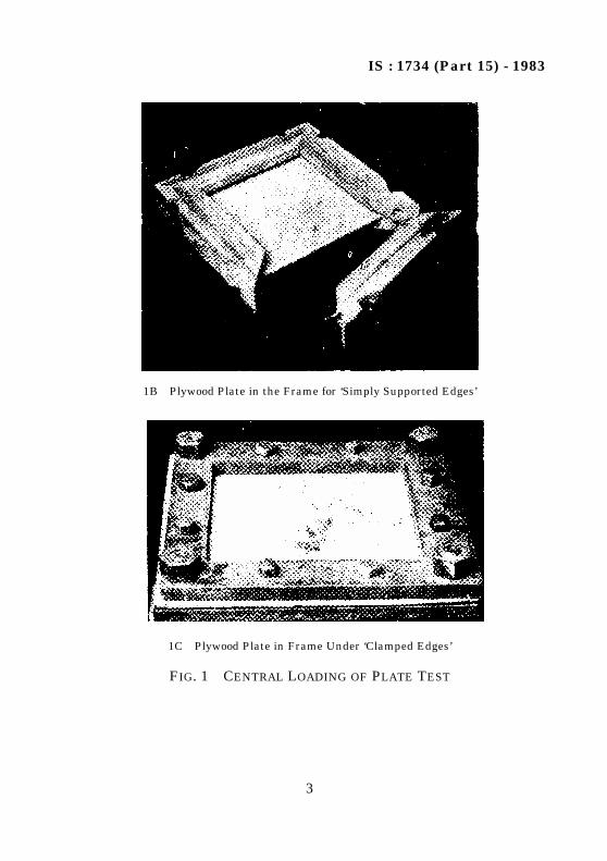
4.1 Loading — The specimen shall be held in a frame shown in Fig.1A and 1B. This frame shall then be supported horizontally on 4pillars at its corners. The load shall be applied vertically at the centreon the top of plywood plate by means of a hemispherical steel ball ofdiameter 10 times the thickness of plywood. Load shall be appliedcontinuously and uniformly at a rate of 0.003 times the length of theplate expressed in cm/min.4.2 Deflection Measurement — The deflection at the centre of theplate shall be taken to the nearrst 0.02 mm at equal increments of loadby means of a dial gauge or scale fixed at the moving head of themachine. The test shall be carried until maximum load is reached andfailure is indicated. The deflection shall be plotted against load, and

IS : 1734 (Part 15) - 1983
2
maximum load P; load P and deflection d at elastic limit shall berecorded.4.3 Clamped Edges Test — If the plywood plate is required to betested under central loading with clamped edges (all the four sidesclamped) the specimen as described above shall be clamped firmly in aframe shown in Fig. 1C and tested as mentioned in 4.1 and 4.2. In thiscase a is the internal distance from edge to edge.
5. REPORT
5.1 The estimate of stiffness shall be calculated from the formula
and reported for a particular type of the plywood.
5.2 All the details shall be recorded under the sub-heads indicatedbelow:
a) Name of the manufacturer/source from whom the plywood isprocured;
b) Type and grade of plywood;c) Construction of plywood in terms of the ratio of thickness of
individual plies;
1A Frame for Holding Plywood Plate with ‘Simply Supported Edges’
FIG. 1 CENTRAL LOADING OF PLATE TEST — Contd
Pa2
dh3----------
IS : 1734 (Part 15) - 1983
3
1B Plywood Plate in the Frame for ‘Simply Supported Edges’
1C Plywood Plate in Frame Under ‘Clamped Edges’
FIG. 1 CENTRAL LOADING OF PLATE TEST

IS : 1734 (Part 15) - 1983
4
d) Species of individual plies;e) Adhesive used;f ) End use of plywood;g) Specimen No./reference;h) Size of specimen;
1) Side,
2) Thickness;j) Mass of specimen at 65 ± 5 percent relative humidity and at a
temperature of 27 ± 2°C;k) Rate of loading;
m) Load at elastic limit P;n) Deflection at elastic limit d;p) Maximum load P; and
q) Stiffness factor simply supported/clamped edges.Pa2
dh3----------

IS : 1734 (Part 16) - 1983
© BIS 1984B U R E A U O F I N D I A N S T A N D A R D SMANAK BHAVAN, 9 BAHADUR SHAH ZAFAR MARG
NEW DELHI 110002
Indian StandardMETHODS OF TEST FOR PLYWOOD
PART 16 VIBRATION OF PLYWOOD PLATE TEST
( Second Revision )UDC 674-419.32 : 620.178.53
1. SCOPE
1.1 This standard (Part 16) covers vibration of plywood plate test.
2. OBJECT
2.1 This test provides a non-destructive method of estimating theresonant characteristics of the material and the stiffness of a plywoodplate under dynamic conditions.
3. METHOD A
3.1 Test Specimen — The test specimen shall be of a square shapewith side not less than 25 times, and not more than 40 times thethickness. The grain direction of face ply shall be parallel to the edge.The thickness ( h ) and the sides ( a ) shall be measured to an accuracyup to 0.1 mm. The test specimen shall be conditioned to a constantmass in a humidity chamber maintained at a relative humidity of65 ± 5 percent and at a temperature of 27 ± 2°C. The mass may bedetermined to an accuracy of 0.01 g.
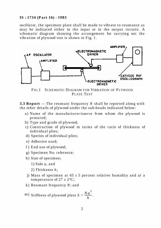
3.2 Procedure — A small thin soft iron piece shall be attached firmlyat the centre of the specimen plate by means of ordinary glue or lac.The specimen shall then be held in the frame which will be held rigidlyin any rig. An electromagnetic driver shall be placed just below thecentre of the sample under the soft iron piece fixed to the sample. Thedistance between soft iron piece and the electromagnet shall besuitably adjusted to get free vibrations. The electromagnet shall beenergized by a calibrated oscillator and the sample shall be made tovibrate. The vibrations shall be packed up by means of anelectromagnetic or piezoelectric pick-up and fed to a cathode rayoscillograph or ac millivoltmeter. By varying the frequency of the
IS : 1734 (Part 16) - 1983
2
oscillator, the specimen plate shall be made to vibrate to resonance asmay be indicated either in the input or in the output circuits. Aschematic diagram showing the arrangement for carrying out thevibration of plywood test is shown in Fig. 1.
3.3 Report — The resonant frequency N shall be reported along withthe other details of plywood under the sub-heads indicated below:
FIG.1 SCHEMATIC DIAGRAM FOR VIBRATION OF PLYWOODPLATE TEST
a) Name of the manufacturer/source from whom the plywood isprocured;
b) Type and grade of plywood;c) Construction of plywood in terms of the ratio of thickness of
individual plies;d) Species of individual plies;e) Adhesive used;f ) End use of plywood;g) Specimen No. reference;h) Size of specimen;
1) Side a, and
2) Thickness h;j) Mass of specimen at 65 ± 5 percent relative humidity and at a
temperature of 27 ± 2°C;k) Resonant frequency N; and
m) Stiffness of plywood plate S = .Na2
h-----------
IS : 1734 (Part 16) - 1983
3
4. METHOD B
4.1 Procedure — Rectangular test specimen of size 70 × 30 cm shallbe supported at two points located at a distance from each end equal to0.224 times its length with suitable end fixtures to simulate zerodisplacement conditions and these shall be excited to a knownfrequency through a variable frequency oscillator and a loudspeaker,placed below the specimen at the middle or at one end. A suitablepick-up shall be used above the surface or at the other end. Theresonant frequency shall be obtained using an oscilloscope, care shallbe taken to see that only the fundamental and not the higherharmonies are recorded.
4.2 Calculation — The Young’s modulus of the specimen (in the grain
direction) shall be determined from the observed values of thefundamental frequency by the following formula:
E =
where
E = dynamic modulus of elasticity in bending in N/mm2;ff = fundamental resonant frequency in cycles per second (Hz);
m = specimen mass in kg;l, b, d = length, width and the thickness of the specimen in mm;
andg = acceleration due to gravity.
2f f l3mg
1 036 bd3---------------------------

IS : 1734 (Part 17) - 1983
© BIS 1984B U R E A U O F I N D I A N S T A N D A R D SMANAK BHAVAN, 9 BAHADUR SHAH ZAFAR MARG
NEW DELHI 110002
Indian StandardMETHODS OF TEST FOR PLYWOOD
PART 17 LONG TIME LOADING TEST OF PLYWOODSTRIPS
( Second Revision )UDC 674-419.32 : 620.178.3
1. SCOPE
1.1 This standard (Part 17) covers long time loading test of plywoodstrips to determine the creep behaviour of plywood and coefficient ofsustained loading. By using standard specimen construction andconstant loading this method may also be used to evaluate creepbehaviour of adhesives for use in plywood.
2. LONG TIME LOADING TEST OF PLYWOOD STRIPS
2.1 Object — The object of this test is to study the creep behaviour ofplywood as well as adhesives used in plywood.
2.2 Test Specimen — The specimen shall be rectangular and itsthickness shall be the thickness of the plywood. The width shall be 2.5cm for thickness less than 6 mm and 5 cm for thickness 6 mm or more.The length shall be 48 times the thickness plus 5 cm, and the graindirection of the face plies shall be parallel to the length. The specimenshall be conditioned to a constant mass at 65 ± 5 percent relativehumidity and at a temperature of 27 ± 2°C. The dimensions shall bemeasured to an accuracy of 0.1 mm and mass shall be taken to anaccuracy of 0.01 g.
2.3 Procedure2.3.1 The test specimen shall be simply supported on horizontalparallel iron rollers having a radius of about 5 mm placed at a distancecentre-to-centre of 48 times the nominal thickness of the specimen.Loading shall be done at the centre of the span and along a lineparallel to the end either by means of suitable lever arrangement( see Fig. 1 ) or simply by means of an iron roller of about 5 mmdiameter and carrying a stirrup ( see Fig. 2 ). The total mass of the

IS : 1734 (Part 17) - 1983
2
roller and stirrup shall not be more than 250 g. The position assumedunder this initial load after a period of 30 seconds shall be treated asthe zero condition.2.3.2 When the test is to be conducted at an elevated temperature theapparatus including specimen (preferably wrapped in polyethylenesheet) shall be kept in the conditioning chamber maintained at thedesired temperature and humidity.
2.3.3 Additional weights such that the total load is equal to 30 percentof maximum load, calculated according to IS : 1734 (Part 11)-1983* ona similar type of specimen shall then be suspended from the stirrupdirectly or by means of lever arrangements and instantaneousdeflection at the mid-point of the span (preferably at the neutral axis)shall be noted by means of a cathetometer or dial gauge placedsuitably at the mid-point of the span. If the lever system shown inFig. 1 is used, the estimation of load is done as below:
where
Deflection shall be measured correct to 0.01 mm. If the creepbehaviour is required to be studied at different loads, these shall beexpressed as percentage of maximum load calculated according toIS : 1734 (Part 11)-1983*.
2.3.4 Deflection shall then be noted every 10 minutes for about2 hours, then every half an hour for another 3 hours, then hourly foranother 5 hours and then twice daily for about a week or till failurehas occurred. A curve between deflection and time t shall be plotted.Creep rate in millimetres per hour or millimetre per day shall becalculated for any portion of the curve (beyond initial deflection).
*Methods of test for plywood : Part 11 Determination of static bending strength( second revision ).
P = load applied to specimen;W = load, including mass of tray, applied at a distance M from
the pivot point;w = mass of lever arm;p = mass of loading plate and rod;B = distance from pivot point to centre of gravity of the
loading arm; andA = distance between pivot point and load point.
P WM + wBA
----------------------------- p+=

IS:1734
(Pa
rt17)
-1983
3
FIG. 1 DIAGRAM SHOWING ARRANGEMENT FOR LONG TIME LOADING TEST OF PLYWOOD STRIP(LEVER ARRANGEMENT)
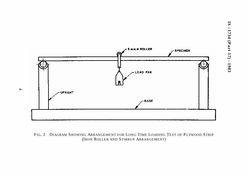
IS:1734 (P
art
17)-
1983
4
FIG. 2 DIAGRAM SHOWING ARRANGEMENT FOR LONG TIME LOADING TEST OF PLYWOOD STRIP(IRON ROLLER AND STIRRUP ARRANGEMENT)

IS : 1734 (Part 17) - 1983
5
For comparison, creep may be expressed as percentage of initialdeflection.
Creep percentage of instantaneous deflection =where
A plot of against time t also provides useful data.
2.3.5 If the creep data for longer periods is not required then the loadshall be removed after 24 hours and after the lapse of a further periodof 24 hours the residual deflection shall be noted.
2.4 Report — Creep rate or creep expressed as percentage of instant-
aneous deflection or curve between and t or deflection after
24 hours under load and residual deflection 24 hours after removal ofload shall be reported with other details as below:
dt = total deflection under constant load at time t, andd0 = initial static deflection under the same load and the same
temperature.
a) Name of the manufacturer/source from whom the plywood isprocured;
b) Type and grade of plywood;c) Construction of plywood in terms of the ratio of thickness of
individual plies;d) Species of individual plies;e) Adhesive used;f) End use of plywood;g) Specimen No./reference;h) Size of specimen;
1) Length,
2) Width, and
3) Thickness;j) Mass of specimen at 65 ± 5 percent relative humidity and at a
temperature of 27 ± 2°C;k) Span;
m) Temperature at which the test is done;n) Mass of stirrup with roller (if loaded by dead loads);
dt d0–
d0---------------------- 100×
dt d0–d0
----------------------
dt d0–d0
----------------------

IS : 1734 (Part 17) - 1983
6
*
3. DETERMINATION OF COEFFICIENT OF SUSTAINED LOADING3.1 Loading — Several percentages of the ultimate breaking load,called here as instantaneous breaking load, determined according toIS : 1734 (Part 10)-1983† shall be used as constant load values forcreep tests on a multiple testing fixture with several units as shown inFig. 1. At least 10 specimens shall be loaded in this fixturesimultaneously. This fixture shall be kept in a room where thetemperature and relative humidity do not fluctuate considerably overthe entire duration of the test for example, a basement room. Timeshall be measured from the instant of loading and the times taken forthe specimens to fail in creep under the action of the different constantloads shall be noted. These times to failure shall be plotted against therespective constant load values expressed as percentage of theinstantaneous breaking load. A curve which is known as the sustainedload shall be drawn through the points as shown in Fig. 3. Anasymptote to the sustained load curve intersects the load axis at avalue known as the limit of sustained loading.
The coefficient of sustained loading Ks is defined as the ratio of thelimit of sustained loading of plywood (σsust) to its instantaneousbreaking load (σbr)
The value of Ks shall be reported to the nearest second decimalplace.
p) Description of arrangement of lever (if loaded by means of lever);q) Load added [expressed in percent of maximum load evaluated
according to IS : 1734 (Part 11)-1983*];r) Deflection readings:
1) Immediately after placing the load,2) 24 hours after placing the load,3) Immediately after removal of load, and4) 24 hours after removal of load;
s) Creep (percent of instantaneous deflection) ....... at time .......;and
t) Observations on the curve between and t.
*Methods of test for plywood : Part 11 Determination of static bending strength( second revision ).
†Methods of test for plywood : Part 10 Determination of compressive strength( second revision ).
dt d0–d0
----------------------
Ksσsust
σbr-------------=

IS : 1734 (Part 17) - 1983
7
FIG. 3 SUSTAINED LOAD CURVE FOR PLYWOOD
IS : 1734 (Part 18) - 1983
© BIS 1984B U R E A U O F I N D I A N S T A N D A R D SMANAK BHAVAN, 9 BAHADUR SHAH ZAFAR MARG
NEW DELHI 110002
Indian StandardMETHODS OF TEST FOR PLYWOOD
PART 18 IMPACT RESISTANCE TEST
( Second Revision )UDC 674-419.32 : 620.178.7
1. SCOPE
1.1 This standard (Part 18) covers impact resistance test on thesurface of plywood, and panel impact resistance.
2. OBJECT
2.1 This test affords a good means of quality assessment of resistanceof the surface of plywood to impact and total panel to breakages bysudden blows.
3. IMPACT RESISTANCE ON SURFACE OF PLYWOOD
3.1 Equipment
3.1.1 Steel Ball — The ball required for dropping on the surface ofplywood shall be of 5 cm diameter and weighing 450 ± 25 g.
3.1.2 Dial Gauge — The dial gauge shall have least count of 0.01 mmand shall be suitably fixed on a plane surface so as to measuremaximum indentation, that is, depression perpendicular to the planeof the surface.
3.2 Test Specimen — The specimen of plywood shall be 20 × 20 cm insize and shall be preconditioned to a constant mass at a relativehumidity of 65 ± 5 percent and at a temperature of 27 ± 2°C.
3.3 Procedure — The specimen shall be placed horizontally on aplane smooth platform. The steelball shall be allowed to fall freely froma height of 100 cm at any 5 different points on the surface of plywood. Ifany indentation is noticed that shall be measured by the dial gauge.
3.4 Report — Maximum indentation shall be reported and anycracking, tearing, etc, shall also be noted.
IS : 1734 (Part 18) - 1983
2
4. PANEL IMPACT RESISTANCE TEST
4.1 Test Specimen — The specimen of plywood shall be 30 × 30 cmwith the face grain parallel and perpendicular to the sides. Thespecimen shall be preconditioned to a constant mass at a relativehumidity of 65 ± 5 percent and at a temperature of 27 ± 2°C.
4.2 Apparatus — The test apparatus shall be as shown in Fig. 1. Thecombined mass of the rod, cone and hemisphere shall be 5 kg. Thediameter of hemisphere shall be 5 cm.
4.3 Procedure — The panel shall be freely supported along all fouredges and the hemisphere shall be made to strike the centre of thepanel. The rod shall be dropped through heights increasing inincrements of 10 mm until fracture of the panel occurs. Fracture isindicated when the hemispherical end has penetrated the panel and isarrested by the flange of the cone.
4.4 The height of drop required to produce fracture shall be taken asthe panel impact strength.
4.5 In case, the specimen does not fail with 5 kg mass from height upto 1 000 mm, the mass shall be increased to 10 kg and the test berepeated from the height of 500 mm.
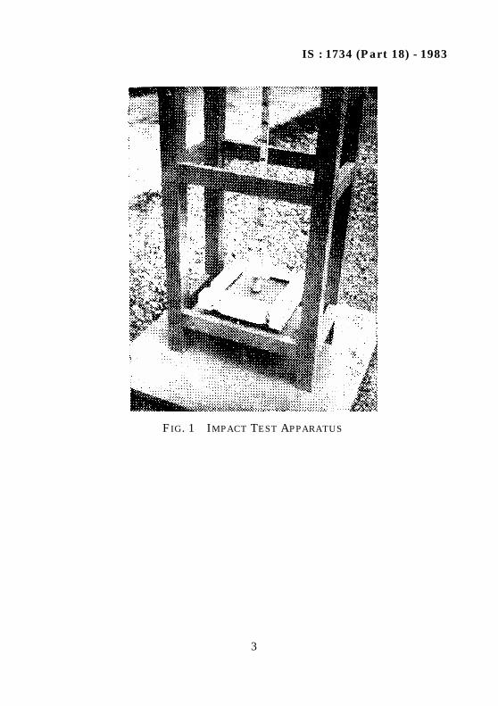
IS : 1734 (Part 18) - 1983
3
FIG. 1 IMPACT TEST APPARATUS

IS : 1734 (Part 19) - 1983
© BIS 1984B U R E A U O F I N D I A N S T A N D A R D SMANAK BHAVAN, 9 BAHADUR SHAH ZAFAR MARG
NEW DELHI 110002
Indian StandardMETHODS OF TEST FOR PLYWOOD
PART 19 DETERMINATION OF NAILS AND SCREW HOLDING POWER
( Second Revision )UDC 674-419.32 : 620.17 : 621.886.2 : 621.882.2
1. SCOPE
1.1 This standard (Part 19) covers the method of test for thedetermination of nails and screw holding power of plywood.
2. OBJECT
2.1 This test is intended to assess the nail and screw holding capacityof the plywood.
3. EQUIPMENT
3.1 The test shall be conducted on a suitable testing machine with anarrangement to pull the screw and nails so as to measure themaximum load required for complete withdrawal.
3.2 Nails shall be 50 mm long and 2.5 mm shank and shall be bright,galvanized, diamond pointed and shall have plain heads. These shallconform to IS : 723-1972*.
3.3 Screws shall be of 4 mm size and 5 cm in length and shall begalvanized gimlet pointed conforming to IS : 6761-1972†.
3.4 Each nail and screw shall be used only once.
4. TEST SPECIMEN
4.1 Plywood strips of 5 × 25 cm shall be glued one over the other as togive total thickness of more than 5 cm. Grain direction of the face plyshall be parallel to length. After conditioning the specimen to constantmass at a relative humidity of 65 ± 5 percent and at a temperature of27 ± 2°C, two nails and two screws mentioned in 3.2 and 3.3 shall be
*Specification for steel countersunk head wire nails ( second revision ).†Specification for countersunk head screws with hexagon socket.
IS : 1734 (Part 19) - 1983
2
driven to a total penetrative of 25 mm exactly at right angle to thesurface of the plywood specimen at a regular distance of 5 cm on themiddle line of the surface. In the case of screw a prebore of 2.5 mmdiameter shall be made.
5. PROCEDURE
5.1 The specimen shall be placed on the testing machine and the nailor screw shall be withdrawn one at a time at a uniform rate of2 mm/min until the nail or screw is pulled out completely. Maximumload for complete withdrawal of nail or screw shall be recorded.
6. REPORT
6.1 The average maximum load for withdrawal of nail or screw shall bereported for the particular type and grade of the plywood.
IS : 1734 (Part 20) - 1983
© BIS 1984B U R E A U O F I N D I A N S T A N D A R D SMANAK BHAVAN, 9 BAHADUR SHAH ZAFAR MARG
NEW DELHI 110002
Indian StandardMETHODS OF TEST FOR PLYWOOD
PART 20 ACIDITY AND ALKALINITY RESISTANCE TEST
( Second Revision )UDC 674-419.32 : 620.193.25/.26
1. SCOPE
1.1 This standard (Part 20) covers acidity and alkalinity resistancetest.
2. OBJECT
2.1 The object of this test is to assess the resistance of plywood surfaceagainst mild acidic or alkaline reaction of the material packed inplywood containers.
NOTE — For testing plywood for use in containers to hold acids or alkalis, strengthtests are necessary. While wood is fairly resistant to acid having pH more than orequal to 2, it is not so resistant to alkalis above pH of 11. So, if the containers aremade of the material for storing such chemicals then an appropriate protectivetreatment shall be given.
3. PREPARATION OF SOLUTIONS FOR TEST
3.1 Dissolve 5 g of chemically pure glacial acetic acid in 100 g distilledwater in a clean beaker stirring by a glass rod. This solution shall betermed as 5 percent acid solution.
3.2 Dissolve 1 g of pure sodium carbonate (anhydrous) in 100 gdistilled water in a clean beaker stirring by a glass rod. This solutionshall be termed as 1 percent alkaline solution.
4. TEST SPECIMEN
4.1 Four specimens of 7.5 cm square size shall be prepared from eachtype of the plywood sheet. These shall be preconditioned to a constantmass at a relative humidity of 65 ± 5 percent and at a temperature of27 ± 2°C.
IS : 1734 (Part 20) - 1983
2
5. PROCEDURE
5.1 All the 4 specimens shall be placed horizontally on separate tables.On the surface of two specimens about 2 ml of acid solution and on thesurface of other two specimens about 2 ml of alkaline solutionmentioned in 3 shall be dropped. The wet part of the specimens shallbe covered by a watch-glass for 6 hours. After the lapse of 6 hours thespecimen shall be washed with water and dried at a room temperaturefor 24 hours. Care shall be taken that the specimens are properlymarked for acidic and alkaline test. The affected surface shall beexamined under oblique light for any blister, delamination, crack,softening and for any remarkable change in colour or lustre.
6. REPORT
6.1 Any visible damage, that is, blister, delamination, crack, softeningor any remarkable change in colour or lustre shall be reportedseparately for acidic and alkaline tests.

Bureau of Indian StandardsBIS is a statutory institution established under the Bureau of Indian Standards Act, 1986 to promoteharmonious development of the activities of standardization, marking and quality certification ofgoods and attending to connected matters in the country.
CopyrightBIS has the copyright of all its publications. No part of these publications may be reproduced in anyform without the prior permission in writing of BIS. This does not preclude the free use, in the courseof implementing the standard, of necessary details, such as symbols and sizes, type or gradedesignations. Enquiries relating to copyright be addressed to the Director (Publications), BIS.
Review of Indian StandardsAmendments are issued to standards as the need arises on the basis of comments. Standards are alsoreviewed periodically; a standard along with amendments is reaffirmed when such review indicatesthat no changes are needed; if the review indicates that changes are needed, it is taken up forrevision. Users of Indian Standards should ascertain that they are in possession of the latestamendments or edition by referring to the latest issue of ‘BIS Catalogue’ and ‘Standards : MonthlyAdditions’.This Indian Standard has been developed by Technical Committee : BDC 20 and amended by CED 20
Amendments Issued Since Publication
Parts No. Amend No. Date of Issue
Part 3 Amd. No. 1 October 1987Part 3 Amd. No. 2 January 1999Part 4 Amd. No. 1 December 1998Part 4 Amd. No. 2 November 2002Part 4 Amd. No. 3 August 2005Part 6 Amd. No. 1 March 1992Part 6 Amd. No. 2 January 2005Part 7 Amd. No. 1 December 2004
BUREAU OF INDIAN STANDARDSHeadquarters:
Manak Bhavan, 9 Bahadur Shah Zafar Marg, New Delhi 110002.Telephones: 323 01 31, 323 33 75, 323 94 02
Telegrams: Manaksanstha(Common to all offices)
Regional Offices: Telephone
Central : Manak Bhavan, 9 Bahadur Shah Zafar MargNEW DELHI 110002
323 76 17323 38 41
Eastern : 1/14 C. I. T. Scheme VII M, V. I. P. Road, KankurgachiKOLKATA 700054
337 84 99, 337 85 61337 86 26, 337 91 20
Northern : SCO 335-336, Sector 34-A, CHANDIGARH 160022 60 38 4360 20 25
Southern : C. I. T. Campus, IV Cross Road, CHENNAI 600113 235 02 16, 235 04 42235 15 19, 235 23 15
Western : Manakalaya, E9 MIDC, Marol, Andheri (East)MUMBAI 400093
832 92 95, 832 78 58832 78 91, 832 78 92
Branches : AHMEDABAD. BANGALORE. BHOPAL. BHUBANESHWAR. COIMBATORE.FARIDABAD. GHAZIABAD. GUWAHATI. HYDERABAD. JAIPUR. KANPUR. LUCKNOW.NAGPUR. NALAGARH. PATNA. PUNE. RAJKOT. THIRUVANANTHAPURAM.VISHAKHAPATNAM