is 12223-2 (1989): data interchange on 6.30 mm wide ... · is 12223 (part 2) : 1989 is0...
TRANSCRIPT

Disclosure to Promote the Right To Information
Whereas the Parliament of India has set out to provide a practical regime of right to information for citizens to secure access to information under the control of public authorities, in order to promote transparency and accountability in the working of every public authority, and whereas the attached publication of the Bureau of Indian Standards is of particular interest to the public, particularly disadvantaged communities and those engaged in the pursuit of education and knowledge, the attached public safety standard is made available to promote the timely dissemination of this information in an accurate manner to the public.
इंटरनेट मानक
“!ान $ एक न' भारत का +नम-ण”Satyanarayan Gangaram Pitroda
“Invent a New India Using Knowledge”
“प0रा1 को छोड न' 5 तरफ”Jawaharlal Nehru
“Step Out From the Old to the New”
“जान1 का अ+धकार, जी1 का अ+धकार”Mazdoor Kisan Shakti Sangathan
“The Right to Information, The Right to Live”
“!ान एक ऐसा खजाना > जो कभी च0राया नहB जा सकता है”Bhartṛhari—Nītiśatakam
“Knowledge is such a treasure which cannot be stolen”
“Invent a New India Using Knowledge”
है”ह”ह
IS 12223-2 (1989): Data Interchange on 6.30 mm WideMagnetic Tape Cartridge Using IMFM Recording at 252 ftpmm,Part 2: Track Format and Method of Recording For DataInterchange in Start/Stop Mode [LITD 16: Computer Hardware,Peripherals and Identification Cards]


IS 12223 (Part 2) : 1989 IS0 806312: 1986
. Indian Standard SPECIFICATION FOR DATA INTERCHANGE
ON 6.30 mm WIDE MAGNETIC TAPE CARTRIDGE
USING IMFM RECORDING,‘AT 252 ftpmm PART 2 TRACK FORMAT AND METHOD OF RECORDING
FOR DATA INTERCHANGE IN START/STOP MODE
UDC 681.327.636:621.798.1 l-52
0 BE 1990
BUREAU OF INDIAN STANDARDS MANAK BHAVAN, 9 BAHADUR SHAH ZAFAR MARG
NEW DELHI 110002
August 1990 Price Group 3

IS 12223 (Part 2) : 1989 IS0 8063/if;,lS86
Indian Standard
SPECIFICATION FOR DATA INTERCHANGE
ON 6.30 mm WIDE MAGNETIC TAPE CARTRIDGE
USING IMFM.RECORDlNG AT 252 ftpmm
PART 2 TRACK FORMAT AND METHOD OF RECORDING
FOR DATA INTERCHANGE IN START/STOP MODE
NATIONAL FOREWORD
This Indian Standard (Part 2). which is identical with IS0 8063/2 : 1986 ‘Information processing-
Data interchange on 6.30 mm (0.25 in) wide magnetic tape cartridge using IMFM recording at
252 ftpmm (6400 ftpi) - Part 2: Track format and method of recording for data interchange in
start/stop mode’, issued by the International Organization for Standardization (ISO) was adopted by
the Bureau of Indian Standards on 15 December 1989 on the recommendation of the Computers,
Business Machines and Calculators Sectional Committee (LTDC 24) and approval of the Electronics
and Telecommunication Division Council.
ln the adopted standard certain terminology and conventions are not identical with those used in
Indian Standards; attention is specially drawn to the following:
a) Comma (,) has been used as a decimal marker while in Indian Standards the current
practice is to use a point (.) as the decimal marker.
b) wherever the words ‘International Standard’ appear, referring to this standard. they should
be read as ‘Indian Standard’.
For the, purpose of this Indian Standard, only metric dimensions are applicable.
CROSS REFERENCE.S
ln this Indian Standard. the following international standards are referred to. Read in their respective places, the following:
Indian Standard Degree of
Correspondence International Standard
IS0 646 Information processing- IS 10315 : 1982 7-bit coded Technically equivalent
IS0 7-bit coded character set for character set for information
information interchange interchange
IS0 2022 Information process-
ing-ISO 7-bit and 8-bit coded
character sets-Code extension
techniques
IS 12326 : 1987 7-bit and El-bit Identical
coded character sets-Code ext-
ension techniques
1

IS 12223 (Part 2) : 1989 IS0 8063/2 : 1986
.
international Standard Indian Standard Degree of
Correspondence
IS0 4341 . Information process- IS 12660 : 1989 Specification for Identical ing-Magnetic tape cassette and magnetic tape cassette and cart- cartridge labelling and file struc- ridge labelling and file structure ture for information interchange for information interchange
IS0 4873 information process- IS 10401 : 1982 8-bit coded Technically ing-IS0 8-bit code-Structure character set for informatlbiif equivalent and rules for implementation interchange.
2
IS 12223 (Part 2) : 1989 IS0 806312 : 1986 _
1 Scope and field of application
IS0 8063 specifies the characteristics of a tape cartridge using 6.30 mm (0.25 in) wide magnetic tape for data interchange be- tween data processing systems.
IS0 2022, Information processing - IS0 Fbit and B-bit coded character sets - Code extension techniques.
IS0 4341, Information processing - Magnetic tape cassette and cartridge labelling and.file structure for information inter- change.
IS0 806311 specifies the dimensional, physical and magnetic characteristics of the cartrid&, and the track layout. IS0 4873, Information processing - IS0 Bbit code - Struc-
ture and rules for implementation. This part of IS0 8063 specifies the quality of the recorded signals, and the track format to be used on a 630 mm (0.25 in) magnetic tape cartridge, recorded at 252 ftpmm I6 400 ftpi) using IMFM recording and the start/stop mode of operation.
4 Data representation
Together with the labelling scheme specified in IS0 4341, IS0 8063/l and IS0 @X3/2 provide for full data interchange between data processing systems.
Characters shall be represented by means of the IS0 ‘I-bit coded character set (see IS0 646) and, where required, by its 7-bit or 8-bit extensions (see IS0 2022) or by means of the IS0 8-bit coded character set (see IS0 4673).
NOTE - Numeric values in the SI and/or Imperial measurement system in this part of IS0 6063 may have been rounded off and therefore are consistent with, but noi exactly equal to, each other. Either system may be used, but the two should be neither intermixed nor reconverted. The original design was made using the Imperial measurement system.
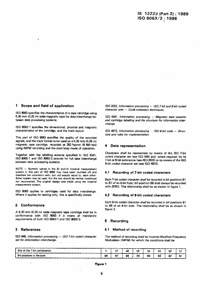
4.1 Recording of 7-bit coded characters
Each 7-bit coded character shall be recorded in bit positions 81 to 87 of an &bit byte; bit-position 138 shall always be recorded with ZERO. The relationship shall be as shown in figure 1.
IS0 8063 applies to cartridges used for data interchange. Where it applies for testing oniy, this is specifically stated.
2 Conformance
A 6.30 mm (0.25 in) wide magnetic tape cartridge shall be in conformance with IS0 8063 if it meets all mandatory requirements of both IS0 806311 and IS0 8063/2.
4.2 Recording of &bit coded characters
Each 8-bit coded character shall be recorded in bit positions 61 to I38 of an Sbit byte. The relationship shall be as shown in figure 2.
5 Recording
3 References 5.1 Method of recording
IS0 646, Information processing - IS0 7-bit coded character set for information interchange.
The method of recording shall be Inverted Modified Frequency Modulation (IMFM) for which the conditions shall be
Bii of the 7-bit combination
Bit-positions in the byte
0 b7 b6 b5 b4 b3 b2 bl
B6 87 B6 85 64 83’ 82 El
Figure 1

IS 12223 (Part 2) : 1989
IS0 806312 : 1986
.
Bits of the 8.bit combination
Bit-positions in the byte
b8 b7 b6 b5 b4 b3 b2 bl
88 B7 1 B6 85 84 83 j 82 1 Bl
Figure 2
1
Figure 3
a) a flux transition shall be written at the centre of a btt cell
containing a ZERO;
5.4 Flux transition spacing
b) a flux transition shall be written at the cell boundary
between consecutive bit cells containing ONES.
54.1 Effect of asymmetry
See figure 3.
At nominal recording density the average variation of spacing
between consecutive flux transitions, taken over 32 flux tran-
sition spacings, shall not be greater than 2 % (see figure 4).
5.2 Measurement 5.4.2 Effect of data patterns
All stgnal measurements shall be made at the point in the read
chain where the amplitude is proportional to the rate of change
of flux in the read head. The ratio of tape speed to the surface
speed of the belt capstan shall be assumed to be exactly 0,76.
In each of the two possible sequences of flux transitions de-
fined by bit pattern OG6OOCQ1ooooooO10 the spacing dt
between the two ZERO flux transitions preceding the ONE bit
cell shall not exceed the average of the four earlier flux tran-
sition spacings by more than 12 %.
5.3 Density of recording
53.1 The nominal recording density shall be 252 ftpmm
16 400 ftpi). The nominal bit cell length shall be 3.97 urn
(156 f.tin).
Similarly, the spacing d2 between the two ZERO flux transitions
following the ONE bit cell shall not exceed the average of the
four subsequent flux transition’spacings by more than 12 %
(see figure 5).
5.3.2 The long-term average bit cell length shall be the
average bit cell length measured over at least 506 OOB flux tran-
sitions. It shall be within f 3 % of the nominal bit cell length.
5.5 Signal amplitude of the interchanged
cartridge
5.51 The average peak-to-peak signal ampfitude at
252 ftpmm (6 400 ftpi) shall not deviate by more than +$ %
from SRA2s2.
5.3.3 The short-term average bit cell length, referred to a par-
ticular bit cell, shall be the average af the lengths of the
preceding four bit cells. It shall be within f 7 % of the long-
term average bit cell length and shall be within + 2 % of *he
average bit cell length of any string of 128 consecutive bit cells
containing the said particular bit cell.
Averaging shall be done over a minimum of 6 400 flux tran-
sitions, which may be segmented into blocks
5.52 No peak-to-peak signal amplitude at 126 ftpmm
(3 200 ftpi) shall be more than three times SRA,,.

; IS 12223 (Part 2) : 1989 IS0 8063/2 : 1986
2 jF3’ldi 7 di+ll < oo2
ii c di+di+l ’ i=l
Figure 4
Id, - 025 D,l < o ,2 > Ia; * 0.2ykl 0.25 D, ’ 0,25 D2
Figbe 5
5.6 Minimum signal amplitude
No cartridge, when interchanged,’ shall contain flux transitions the base-to-peak amplitudes of which are less than 35 % of half SRA,.
5.7 Erasure
After erasure, any signal amplitude shall be less than 5 % of the SRA=
5.6 Recording offset angle
On any track the angle that a flux transition across the track makes with a line perpendicular to Reference Plane B shall not exceed 9 minutes of arc.
6 Track format
The layout and positioning of tracks shalt be as specified in IS0 806311.
6.1 Use of tracks
Each track shall be a data track and shall be written serially in the direction from the BOT marker to the EOT marker. No data
for interchange shall be written between the BOT marker and the LP marker. Data for interchange shall be written after seni ing the LP marker and may continue to be mitten after sensing the EW marker.
6.2 Location of characters on the tracks
Each character shall be located in a byte of eight bit positions along the track numbered from 1 to 8 in order of recording.
6.3 Sequence of recording
The least-significant bit shall be record&d first. The information to ba interchanged shall be recorded serially by bit and by character.
Bit-positions: ..A321 187884321 18788432...
Forward tape motion :
Resuithg recording direction:
6.4 Data block
‘A data Mock shall consist of a preamble, a data portion, a CRC character and a postamble (see figure 61.

IS 12223 (Part 2) : 1989 IS0 8063/2 : 1986
PREAMBLE DATA CRC POSTAMBLE .
@IO.. 001 8-bit bytes
one 16 bit
byte
39 ZEROS minimum 12 bytes minimum 39 ZEROS minimum
47 ZEROS maximum 8 196 bytes maximum 47 ZEROS maximum
Figure 6
6.4.1 Preamble 6.5 Control block
The preamble, consisting of not less than 39 ZEROS Land not more than 47 ZEROS followed by a single ONE, shall be written
’
A control block shall consist of a preamble, two bytes of eight
ZEROS, and a postamble.
immediately preceding data in each data block.
6.4.2 Data portion
The data portion of a data block shall contain a minimum of 12 data bytes and a maximum of 8 192 data bvtes.
6.6 Gaps
6.6.1 Integrity of gaps
The gaps shall be erased.
6.4.3 Cyclic Redundancy Check (CRC) 6.6.2 Initial gap
The f6 bits following the data portion of a data block shall be a Cyclic Redundancy Check (CRC) character. This l&bit character shall be written in each data block following the data portion and immediately preceding the postamble, the least significant bit being recorded first. The polynomial generating the CRC shall be
l-16 + x15 + x2 + 1
The gap between the LP marker and the first data block shall be 152.4 mm min. 16 in min.) and 1.2 m max. (48 in max.).
6.6.3 Interblock gaps
The interblock gap shall have a minimum length of 31 mm (1.22 in) and a maximum length of 1.2 m 146 in). Any gap in excess of 1.2 m (46 in) shall be considered as the end of data on this track.
6.4.4 Poetemble
The postemble, consisting of a ONE followed by not less than 39 ZEROs and not more than 47 ZEROS. shall be written immediately following the CRC in each data L’. ok.
NOTE - The ability to start or stop within a gap of a given length is dependent on the tape speed selected from the range specified in IS0 8663/l sub-clause 7.5 and the acceleration and deceleration also specified in IS0 8%3/l sub-clause 7.7.
\

Bareno 01 Indian Standards .
BIS is a statutory institution established under the Bureau of Indian Standarde Act, 2986 to promote harmonious development of the atiivities of standardization, marking and quality certification of goods and attending to connected ahatters in the country.
Copyright
BIS has the copyright of all its publications. No part of these publications may be reproduced in any form without the prior permission in writing of BIS. This does not preclude the free use, in the course of implementing the standard, of necessary details, such as symbols and sizes, type or grade des,ignations. Enquiries relating to copyright be addressed to the Director ( Publications ), BIS.
Revision of Indian Standards
Indian Standards are reviewed periodically and revised, when nece’ssary and amendments, if any, are issued from time 10 time. Users of Indian Standards should ascertain that they are in possession of the latest amendments or edition. Comments on this Indian Standard may be sent to BIS giving the following reference :
Dot. Na. LTD 24 (1308)
Amendments Issoed Since Poblication
Amend No. Date of Issue Text Affected
Headquarters :
BUREAU OF INDIAN STANDARDS
Manak Bhavan, 9 Bahadur Shah Zafar Marg, New Delhi 110002 Telephones : 331 01 31, 331 13 75
Regional Offices :
Central : Manak Bhavan, 9 Bahadur Shah Zafar Marg NEW DELHI 110002
Eastern : l/14 C.I.T. Scheme VII M, V.I.P. Road, Maniktola CALCUTTA 700054
Northern : SC0 445-446, Sector 35-C, CHANDIGARH 160036
Telegrams :]Manaksanstha ( Common to all Of&es )
Telephone
-331 01 31 331 13 75
37 86 62
2 18 43
Southern : C.I.T. Campus, IV Cross Road, MADRAS 600113
Western : Manakalaya, E9 MIDC, Marol, Andheri ( East ) BOMBAY 400093
4129 16
6 32 92 95
Branches : AHMADABAD. BANGALORE. BHOPAL. BHUBANESHWAR. COIMBATORE, FARIDABAD, GHAZIABAD. GUWAHATI. HYDERABAD. JAIPUR. KANPUR. PATNA. TRIVANDRUM.
Printed at Kay Kay Printers 150-D Kamla Nagar Delhi - 110007 \
c