is 10462-1 (1983): fictitious calculation method for ...3.5 armour - the fictitious diameter over...
TRANSCRIPT

Disclosure to Promote the Right To Information
Whereas the Parliament of India has set out to provide a practical regime of right to information for citizens to secure access to information under the control of public authorities, in order to promote transparency and accountability in the working of every public authority, and whereas the attached publication of the Bureau of Indian Standards is of particular interest to the public, particularly disadvantaged communities and those engaged in the pursuit of education and knowledge, the attached public safety standard is made available to promote the timely dissemination of this information in an accurate manner to the public.
इंटरनेट मानक
“!ान $ एक न' भारत का +नम-ण”Satyanarayan Gangaram Pitroda
“Invent a New India Using Knowledge”
“प0रा1 को छोड न' 5 तरफ”Jawaharlal Nehru
“Step Out From the Old to the New”
“जान1 का अ+धकार, जी1 का अ+धकार”Mazdoor Kisan Shakti Sangathan
“The Right to Information, The Right to Live”
“!ान एक ऐसा खजाना > जो कभी च0राया नहB जा सकता है”Bhartṛhari—Nītiśatakam
“Knowledge is such a treasure which cannot be stolen”
“Invent a New India Using Knowledge”
है”ह”ह
IS 10462-1 (1983): Fictitious Calculation Method forDetermination of Dimensions of Protective Coverings ofCables, Part I: Elastomeric and Thermoplastic InsulatedCables [ETD 9: Power Cables]


IS : 10462 ( Part I ) - 1983
Indian Standard
FICTITIOUS CALCULATION METHOD FOR DETERMINATION OF DIMENSIONS OF PROTECTIVE COVERINGS OF CABLES
PART I ELASTOMERIC AND THERMOPLASTIC INSULATED CABLES
Power Cables Sectional Committee, ETDC 59
Chairnan
SHRI M. L. DONQRE
Members
Representing
Bombay Electric Supply & Transport Undertaking, Bombay
SHRI S. M. SAKHALKAR ( Alternate to Shri M. L. Dongre )
SKRI J. P. ANAL Bharat Heavy Electricals Ltd, Hyderabad SHRI B. P. RAI ( Alternate )
SHRI M. R. BHAT Tata Consulting Engineers, Bombay SHRI D. K. BASU ( Alternate )
CHIEF ENGINEER ( ELECTRICAL ) I Central Public Works Department, New Delhi S U~VEY on OF WORKS
( ELECT ) V ( Alternate ) DR K. DAS GUPTA Calcutta Electric Supply Corporation ( India ) Ltd,
Calcutta SH~I P. NEOOI ( Alternate )
DIRECTOR Central Power Research Institute, Bangalore SHRI M. C. RATRA ( Alternate )
DIRECTOR OB MINES SAFETY Directorate General of Mines Safety, Dhanbad (ELECT)(HQ)
DIRECTOR OF MINES SAFETY SHRI RA”,l;E,rDLT{terxafP )
Cable and Conductor Manufacturers’ .4ssociation of
SHRI K. G. WARRIER ( Alternate ) India, New Delhi
SHRI P. GHOSE Indian Cable Co Ltd, Jamshedpur SHRI S. BHATT~CHARYA ( Alternate )
Srrnr M. M. HONAVAR Cable Corporation of India Ltd, Bombay SHRI K. G. MATHEW ( Alternate )
SHRI K. S. JOSHI Bombay Suburban Electric Supply Ltd, Bombay SHRI R. K. S~HG_4~ ( Alternate )
( Continued on page 2 )
@ Copyright 1983 INDIAN STANDARDS INSTITUTION
This publication is protected under the Indian Copyright Act ( XIV of 1957 ) and reproduction in whole or in part by any means except with written permission of the publisher shall he deemed to he an infringement of copyright under the said Act.

IS : 10462 ( Part I ) - 1983
( Continued from page 1 )
Members Representing
SHRI S. L. KAKKAR Universal Cables Ltd, Satna SHRI R. C. AGRAWAL ( Allertrate )
SI~RI RAJ K. MITAL Delhi Electric Supply Undertaking, New Delhi S~ltr M. K. AHUJA ( Alternate )
LT-COL S. S. MOHANTY Controllerate of Inspection Electronics, Bangalore Smtr A. L. KHANNA ( Alternate )
SHRI B. K. MUNDHARA Oriental Power Cables Ltd, Kota SHRI A. K. JAIN ( Alternate )
SIIRI R. V. NanAYANAN Directorate General of Supplies & Disposals
SHRI D. R. CHANDRA ( Allernnle ) ( Inspection Wing ), New Delhi
SHRI H. M. PAI The Federation of Electricity Undertakings of India, Bombay
SMT C. BALIGA ( Alternate ) SHRI H. C. PANDE Directorate of Technical Development & Production
( Air ), New Delhi SHRI V. K. SHARMA ( Alternate )
SWRI S. N. PARWAL The Premier Cable Co Ltd. Ernakulam ( Kerala 1 SIIHI A. K. RAMAN Asian Cables Corporation Ltd, Bombay ’ SHRI L. K. SAN~I~I Fort Gloster Industries Ltd, Howrah
’
SHRI A. S. BHATTACHARJEE ( Alternate ) DR M. S. SUKHIJA Punjab Research Institute, Rajpura SHRI U. S. VERMA National Test House, Calcutta
SH~I R. RAMAKRISHNA ( Alternate ) SHKI S. P. S~CIIDEV, Director General, IS1 ( Ex-o#cio Member )
Director ( Elec tech )
Secretary
SHRI K. M. BHATIA Deputy Director ( Elec tech ), IS1
2

IS : 10462 ( Part I ) - 1983:
Indian Standard FICTITIOUS CALCULATION METHOD FOR
DETERMINATION OF DIMENSIONS OF PROTECTIVE COVERINGS OF CABLES :
PART I ELASTOMERIC AND THERMOPLASTIC INSULATED CABLES
0. FOREWORD
0.1 This Indian Standard ( Part I ) was adopted by the Indian Standards Institution on 24 February 1983, after the draft finalized by the Power Cables Sectional Committee had been approved by the Electrotechnical Division Council.
0.2 Indian Standards on cables specify some of the parameters such as inner and outer sheath thickness and armour size on the basis of calculated nominal cable diameters which are not necessarily the same as actual values achieved in production. In borderline cases, queries can arise if any of these parameters does not correspond to the actual diameter because calculated diameter may be slightly different.
0.3 To avoid variation in shaped conductor dimensions and method of calculation from manufacturer to manufacturer, the fictitious calculation method has been invented. The idea is to ignore the shape and degree of compactness of conductors and to calculate fictitious diameters from formulae based on the cross-sectional area of conductor, insulation thick- ness and number of cores. Various parameters which are independent of slight difference in manufacturing practices are then related to fictitious diameters by formulae or by tables. This method helps in standardizing cable designs, different parameters being pre-calculated and specified for each size of cables.
0.4 The fictitious calculation is used only to determine dimensions of sheaths and cable coverings. It is not a replacement for the calculation of normal diameters required for practical purposes, which should be calculated separately.
0.5 The details regarding fictitious calculations for paper insulated cables will be covered in Part II of the standard.
3
IS : 10462 ( Part I ) - 1983
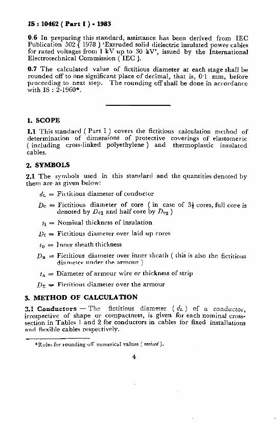
0.6 In preparing this standard, assistance has been derived from IEC Publication 502 ( 1978 ) ‘Extruded solid dielectric insulated power cables for rated voltages from 1 kV up to 30 kV’, issued by the International Electrotechnical Commission ( IEC ).
0.7 The calculated value of fictitious diameter at each stage shall be rounded off to one significant place of decimal, that is, 0.1 mm, before proceeding to next step. The rounding off shall be done in accordance with IS : 2-1960”.
1. SCOPE
1.1 This standard ( Part I ) covers the fictitious calculation method of determination of dimensions of protective coverings of elastomeric ( including cross-linked polyethylene ) and thermoplastic insulated cables.
2. SYMBOLS
2.1 The symbols used in this standard and the quantities denoted by them are as given below:
& = Fictitious diameter of conductor
DC = Fictitious diameter of core ( in case of 35 cores, full core is denoted by DC1 and half core by DC2 )
ti = Nominal thickness of insulation
DI = Fictitious diameter over laid up cores
tg = Inner sheath thickness
Da = Fictitious diameter over inner sheath ( this is also the fictitious
diameter under the armour )
tA = Diameter of armour wire or thickness of strip
Dx - Fictitious diameter over the armour
3. METHOD OF CALCULATION
3.1 Conductors - The fictitious diameter ( dL ) of a conductor, irrespective of shape or compactness, is given for each nominal cross- section in Tables 1 and 2 for conductors in cables for fixed installations and flexible cables respectively.
*Rules for rounding off numerical values ( mised ).
4

~-“---__- I__.__ ___
IS : 10462 ( Part I ) - 1983
TABLE 1 FICTITIOUS DIAMETER OF CONDUCTOR IN CABLES FOR FIXED INSTALLATIONS
( Clause 3.1 )
NOMINAL CROSS- & NOMINAL CROSS- SECTIONAL AREA SECTIONAL AREA
&
OF CONDUCTOR I
OFCONDUCTOR
(1) InIn2
1.5
2’5
4
6
10
16
25
35
50
70
(2) mm
1’4
l-8
2.3
2.8
3.6
4.5
5.6
6.7
8.0
9.4
(1) mm2
(2) mm
95 11.0
120 12.4 150 13.8 185 15.3
240 17.5
300 19-5
400 22.6 500 25.2 630 28-3 800 31.9
1000 35.7
TABLE 2 FICTITIOUS DIAMETER OF CONDUCTOR IN FLEXIBLE CABLES ( Clause 3.1 )
NOMINAL CROSS- SECTIO~JAL ARE? OF CONDUCTOR
(1)
mma
0.5
0.75
1
1’5
2.5
4
6
10
16
25
35
(2) mm
NOMINALCROSS- SECTIONAL AREA OF CONDUCTOR
(1)
mmz
(2) mm
0.9 50 10.3 1.1 70 12.4 1.3 95 145 l-6 120 16.0
2.0 150 18.0
2’6 185 20.0
3.6 240 23.0
46 300 26.0
5.7 400 30-o
7.1 500 33.3
8.5 630 37.0
&
5

IS : 10462 ( Part I ) - 1983
3.2 Cores - The fictitious diameter, DC, of any core is given by:
a) for unscreened cores:
De = dL -/-2trmm
b) for cables of rated voltage requiring screening, to allow for semi- conducting layers with and without metallic screen:
DC = dL + 2 tl + 3.0 mm
where t1 is the nominal thickness of insulation ( in mm ) as given in individual cable specification.
3.3 Diameter Over Laid-Up Cores - The fictitious diameter over laid-up cores, Df, is given by the following:
a) For cables having all cores of the same fictitious diameter:
Dr = kDe mm
where the coefficient k is as given in Table 3.
b) For 39 core cables:
Df = 2.42 ( 3 &I + D,z )
4 mm
where
DC1 = fictitious diameter of full ( main ) core, including metallic layer, if any; and
DC2 = fictitious diameter of half core ( core having reduced neutral conductor ).
c) For cables with cradle separator:
Df = k ( DC + 2.5 ) - 2.5 mm
where the coefficient k is as given in Table 3.
3.4 Inner Sheath - The fictitious diameter over the inner sheath, Do, is given by:
DB = Df + 2tg mm
where
tB = thickness of inner sheath ( in mm ) as specified in indivi- dual cable specification.
6

IS : 10462 ( Part I ) - 1983
TABLE 3 ASSEMBLY COEFFICIENT FOR CALCULATION OF FICTITIOUS DIAMETER OVER LAID-UP CORES
( Clause 3.3 )
N~JMBER OF ASSEMBLY CORES COEFFICIENT
k
(1) (2)
2 2.00
3 2.16 4 2.42
5 2.70’
6 3.00
7 3.00
7* 3.35
8 3.45
82 3.66 9 3.80
9’ 4.00
10 4.00
10” 4.40
11 4.00
12 4.16
12. 5.00
13 4.41
14 441
15 4.70 16 4.70
17 5.00
18 5.00
18* 7.00
19 5.00
20 5.33
21 5.33
22 5.67
23 5.67
24 6.00
‘Cores assembled in one layer.
NUMBER OF CORES
(1) 25
26
27
28
29
30
31
32 33
34
35
36
37
38
39
40
41
42
43
44
45
46
47
48
52
61
ASSEMBLY COEFFICIENT
k
(2)
6.00
6.00
6.15
6.41
6.41
6.41
6.70
6.70
6.70
7.00
7‘00
7.00
7.00
7-33
7.33
7.33
7-67
7-67
7.67
8.00
a.00
8.00
a.00 8.15
8.41
wll
7

IS : 10462 ( Part I ) - 1983
3.5 Armour - The fictitious diameter over the armour, &, is given by:
Dx= Dg i-2 tA mm
where
tA = diameter of the armour wire or thickness of strip ( in mm ) as specified in individual cable specification.
NOTE - In case of pliable wire armoured cables, tA refers to the diameter of stranded armour, which is taken to be equal to 3 times diameter of individual armour wire.
8