irvine, ca 92618 - edgecore networks · pdf file38 tesla irvine, ca 92618 phone: (949)...
TRANSCRIPT

38 TeslaIrvine, CA 92618Phone: (949) 679-8000
EZ ConnectTM g 108 Mbps Wireless AP User Guide
From SMC’s EZ line of low-cost workgroup LAN solutions
July 2005Revision #: R01, F1.0

CopyrightInformation furnished by SMC Networks, Inc. (SMC) is believed to be accurate and reliable. However, no responsibility is assumed by SMC for its use, nor for any infringements of patents or other rights of third parties which may result from its use. No license is granted by implication or otherwise under any patent or patent rights of SMC. SMC reserves the right to change specifications at any time without notice.
Copyright © 2005 bySMC Networks, Inc.
38 TeslaIrvine, CA 92618
All rights reserved.
Trademarks:SMC is a registered trademark; and EZ Connect is a trademark of SMC Networks, Inc. Other product and company names are trademarks or registered trademarks of their respective holders.
i
COMPLIANCES
Federal Communication Commission Interference StatementThis equipment has been tested and found to comply with the limits for a Class B digital device, pursuant to Part 15 of the FCC Rules. These limits are designed to provide reasonable protection against harmful interference in a residential installation. This equipment generates, uses and can radiate radio frequency energy and, if not installed and used in accordance with the instructions, may cause harmful interference to radio communications. However, there is no guarantee that interference will not occur in a particular installation. If this equipment does cause harmful interference to radio or television reception, which can be determined by turning the equipment off and on, the user is encouraged to try to correct the interference by one of the following measures:
• Reorient or relocate the receiving antenna• Increase the separation between the equipment and receiver• Connect the equipment into an outlet on a circuit different from that to which the
receiver is connected• Consult the dealer or an experienced radio/TV technician for help
This device complies with Part 15 of the FCC Rules. Operation is subject to the following two conditions: (1) This device may not cause harmful interference, and (2) this device must accept any interference received, including interference that may cause undesired operation.
FCC Caution: Any changes or modifications not expressly approved by the party responsible for compliance could void the user's authority to operate this equipment.
IMPORTANT NOTE:IEEE 802.11b or 802.11g operation of this product in the U.S.A. is firmware-limited to channels 1 through 11.
COMPLIANCES
ii
Industry Canada StatementOperation is subject to the following two conditions:
This device may not cause interference and this device must accept any interference, including interference that may cause undesired operation of the device
This device has been designed to operate with an antenna having a maximum gain of 1.5 dBi.
Antenna having a higher gain is strictly prohibited per regulations of Industry Canada. The required antenna impedance is 50 ohms.
To reduce potential radio interference to other users, the antenna type and its gain should be so chosen that the EIRP is not more than required for successful communication.
EC Declaration of Conformity
SMC contact for these products in Europe is:
SMC Networks Europe,Edificio Conata II,Calle Fructuos Gelabert 6-8, 2o, 4a,08970 - Sant Joan Despi,Barcelona, Spain.
Marking by the above symbol indicates compliance with the Essential Requirements of the R&TTE Directive of the European Union (1999/5/EC). This equipment meets the following conformance standards:
• EN 300 328-1 December 2001 V1.3.1• EN 300 328-2 December 2001 V1.2.1• EN 301 489-1 September 2001 V1.4.1• EN 301 489-17 September 2000 V1.2.1• EN 60950 January 2000
COMPLIANCES
iii
Countries of Operation & Conditions of Use in the European CommunityThis device is intended to be operated in all countries of the European Community. Requirements for indoor vs. outdoor operation, license requirements and allowed channels of operation apply in some countries as described below:
Note: The user must use the configuration utility provided with this product to ensure the channels of operation are in conformance with the spectrum usage rules for European Community countries as described below.
• This device requires that the user or installer properly enter the current country of operation in the command line interface as described in the user guide, before operating this device.
• This device will automatically limit the allowable channels determined by the current country of operation. Incorrectly entering the country of operation may result in illegal operation and may cause harmful interference to other system. The user is obligated to ensure the device is operating according to the channel limitations, indoor/outdoor restrictions and license requirements for each European Community country as described in this document.
• This device may be operated indoors or outdoors in all countries of the European Community using the 2.4 GHz band: Channels 1 - 13, except where noted below.
- In Italy the end-user must apply for a license from the national spectrum authority to operate this device outdoors.
- In Belgium outdoor operation is only permitted using the 2.46 - 2.4835 GHz band: Channel 13.
- In France outdoor operation is only permitted using the 2.457 - 2.472 GHz band: Channels 10 - 13.

COMPLIANCES
iv
Declaration of Conformity in Languages of the European Community
English Hereby, SMC Networks, declares that this Radio LAN device is in compliance with the essential requirements and other relevant provisions of Directive 1999/5/EC.
Finnish Valmistaja SMC Networks vakuuttaa täten että Radio LAN device tyyppinen laite on direktiivin 1999/5/EY oleellisten vaatimusten ja sitä koskevien direktiivin muiden ehtojen mukainen.
Dutch Hierbij verklaart SMC Networks dat het toestel Radio LAN device in overeenstemming is met de essentiële eisen en de andere relevante bepalingen van richtlijn 1999/5/EG
Bij deze SMC Networks dat deze Radio LAN device voldoet aan de essentiële eisen en aan de overige relevante bepalingen van Richtlijn 1999/5/EC.
French Par la présente SMC Networks déclare que l'appareil Radio LAN device est conforme aux exigences essentielles et aux autres dispositions pertinentes de la directive 1999/5/CE
Swedish Härmed intygar SMC Networks att denna Radio LAN device står I överensstämmelse med de väsentliga egenskapskrav och övriga relevanta bestämmelser som framgår av direktiv 1999/5/EG.
Danish Undertegnede SMC Networks erklærer herved, at følgende udstyr Radio LAN device overholder de væsentlige krav og øvrige relevante krav i direktiv 1999/5/EF
German Hiermit erklärt SMC Networks, dass sich dieser/diese/dieses Radio LAN device in Übereinstimmung mit den grundlegenden Anforderungen und den anderen relevanten Vorschriften der Richtlinie 1999/5/EG befindet". (BMWi)
Hiermit erklärt SMC Networks die Übereinstimmung des Gerätes Radio LAN device mit den grundlegenden Anforderungen und den anderen relevanten Festlegungen der Richtlinie 1999/5/EG. (Wien)
Greek
COMPLIANCES
v
Safety Compliance
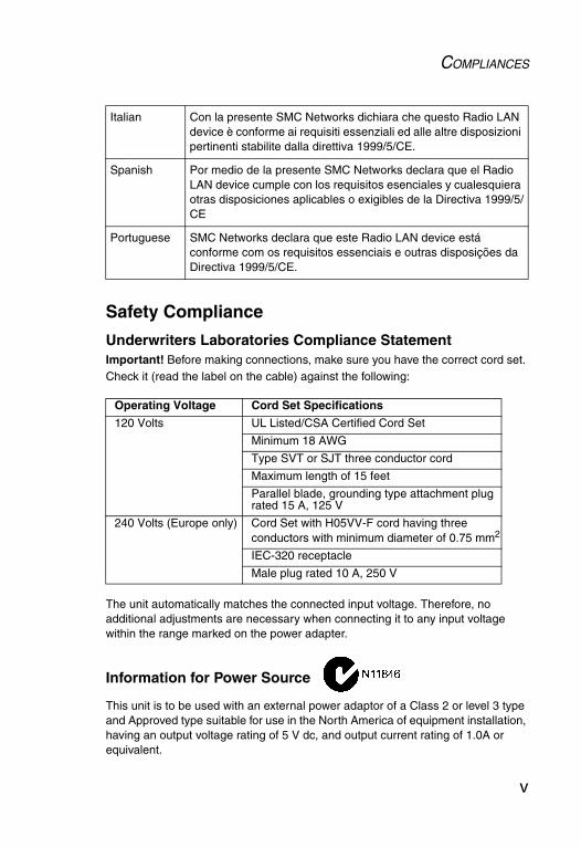
Underwriters Laboratories Compliance StatementImportant! Before making connections, make sure you have the correct cord set. Check it (read the label on the cable) against the following:
The unit automatically matches the connected input voltage. Therefore, no additional adjustments are necessary when connecting it to any input voltage within the range marked on the power adapter.
Information for Power Source
This unit is to be used with an external power adaptor of a Class 2 or level 3 type and Approved type suitable for use in the North America of equipment installation, having an output voltage rating of 5 V dc, and output current rating of 1.0A or equivalent.
Italian Con la presente SMC Networks dichiara che questo Radio LAN device è conforme ai requisiti essenziali ed alle altre disposizioni pertinenti stabilite dalla direttiva 1999/5/CE.
Spanish Por medio de la presente SMC Networks declara que el Radio LAN device cumple con los requisitos esenciales y cualesquiera otras disposiciones aplicables o exigibles de la Directiva 1999/5/CE
Portuguese SMC Networks declara que este Radio LAN device está conforme com os requisitos essenciais e outras disposições da Directiva 1999/5/CE.
Operating Voltage Cord Set Specifications
120 Volts UL Listed/CSA Certified Cord Set
Minimum 18 AWG
Type SVT or SJT three conductor cord
Maximum length of 15 feet
Parallel blade, grounding type attachment plug rated 15 A, 125 V
240 Volts (Europe only) Cord Set with H05VV-F cord having three conductors with minimum diameter of 0.75 mm2
IEC-320 receptacle
Male plug rated 10 A, 250 V
COMPLIANCES
vi
Wichtige Sicherheitshinweise (Germany)1. Bitte lesen Sie diese Hinweise sorgfältig durch.
2. Heben Sie diese Anleitung für den späteren Gebrauch auf.
3. Vor jedem Reinigen ist das Gerät vom Stromnetz zu trennen. Verwenden Sie keine Flüssigoder Aerosolreiniger. Am besten eignet sich ein angefeuchtetes Tuch zur Reinigung.
4. Die Netzanschlu ßsteckdose soll nahe dem Gerät angebracht und leicht zugänglich sein.
5. Das Gerät ist vor Feuchtigkeit zu schützen.
6. Bei der Aufstellung des Gerätes ist auf sicheren Stand zu achten. Ein Kippen oder Fallen könnte Beschädigungen hervorrufen.
7. Die Belüftungsöffnungen dienen der Luftzirkulation, die das Gerät vor Überhitzung schützt. Sorgen Sie dafür, daß diese Öffnungen nicht abgedeckt werden.
8. Beachten Sie beim Anschluß an das Stromnetz die Anschlußwerte.
9. Verlegen Sie die Netzanschlußleitung so, daß niemand darüber fallen kann. Es sollte auch nichts auf der Leitung abgestellt werden.
10. Alle Hinweise und Warnungen, die sich am Gerät befinden, sind zu beachten.
11. Wird das Gerät über einen längeren Zeitraum nicht benutzt, sollten Sie es vom Stromnetz trennen. Somit wird im Falle einer Überspannung eine Beschädigung vermieden.
12. Durch die Lüftungsöffnungen dürfen niemals Gegenstände oder Flüssigkeiten in das Gerät gelangen. Dies könnte einen Brand bzw. elektrischen Schlag auslösen.
13. Öffnen sie niemals das Gerät. Das Gerät darf aus Gründen der elektrischen Sicherheit nur von authorisiertem Servicepersonal geöffnet werden.
14. Wenn folgende Situationen auftreten ist das Gerät vom Stromnetz zu trennen und von einer qualifizierten Servicestelle zu überprüfen:
a.Netzkabel oder Netzstecker sind beschädigt.b. Flüssigkeit ist in das Gerät eingedrungen.c. Das Gerät war Feuchtigkeit ausgesetzt.d.Wenn das Gerät nicht der Bedienungsanleitung entsprechend funktioniert
oder Sie mit Hilfe dieser Anleitung keine Verbesserung erzielen.e.Das Gerät ist gefallen und/oder das Gehäuse ist beschädigt.f. Wenn das Gerät deutliche Anzeichen eines Defektes aufweist.
15. Stellen Sie sicher, daß die Stromversorgung dieses Gerätes nach der EN 60950 geprüft ist. Ausgangswerte der Stromversorgung sollten die Werte von AC 7,5-8 V, 50-60 Hz nicht über oder unterschreiten sowie den minimalen Strom von 1 A nicht unterschreiten.
Der arbeitsplatzbezogene Schalldruckpegel nach DIN 45 635 Teil 1000 beträgt 70 dB(A) oder weniger.

vii
TABLE OF CONTENTS
EZ Connect™ g 108 Mbps Wireless AP . . . . . . . . 1Introduction . . . . . . . . . . . . . . . . . . . . . . . . . . . . . . . . . . . . . 1Package Checklist . . . . . . . . . . . . . . . . . . . . . . . . . . . . . . . . 2
Hardware Description . . . . . . . . . . . . . . . . . . . . . . . 3Applications . . . . . . . . . . . . . . . . . . . . . . . . . . . . . . . . . . . . . 4LED Indicators . . . . . . . . . . . . . . . . . . . . . . . . . . . . . . . . . . . 5System Requirements . . . . . . . . . . . . . . . . . . . . . . . . . . . . . 6
Hardware Installation . . . . . . . . . . . . . . . . . . . . . . . 7
System Configuration . . . . . . . . . . . . . . . . . . . . . . . 8
EZ Installation Wizard . . . . . . . . . . . . . . . . . . . . . . . 9Using IPCONFIG . . . . . . . . . . . . . . . . . . . . . . . . . . . . . . . . 10
Configuring Your IP Address . . . . . . . . . . . . . . . . 11Windows 2000 . . . . . . . . . . . . . . . . . . . . . . . . . . . . . . . . . . 11Windows XP . . . . . . . . . . . . . . . . . . . . . . . . . . . . . . . . . . . . 13
Web Management . . . . . . . . . . . . . . . . . . . . . . . . . 16Browser Configuration . . . . . . . . . . . . . . . . . . . . . . . . . . . . 16
Disable Proxy Connection . . . . . . . . . . . . . . . . . . . . . . . 16Internet Explorer (5.5 or above) in Microsoft Windows . . 16Internet Explorer in Macintosh . . . . . . . . . . . . . . . . . . . . 16
Navigating the Web Browser Interface . . . . . . . . . . . . . . . . 17Making Configuration Changes . . . . . . . . . . . . . . . . . . . 17Login Screen . . . . . . . . . . . . . . . . . . . . . . . . . . . . . . . . . . 18
Setup Wizard . . . . . . . . . . . . . . . . . . . . . . . . . . . . . . . . . . . 19Getting Started . . . . . . . . . . . . . . . . . . . . . . . . . . . . . . . . 19Operating Mode . . . . . . . . . . . . . . . . . . . . . . . . . . . . . . . 20Wireless Settings . . . . . . . . . . . . . . . . . . . . . . . . . . . . . . 21Confirm Settings . . . . . . . . . . . . . . . . . . . . . . . . . . . . . . . 24
Home Network Settings . . . . . . . . . . . . . . . . . . . . . . . . . . . 25Status . . . . . . . . . . . . . . . . . . . . . . . . . . . . . . . . . . . . . . . 25
TABLE OF CONTENTS
viii
Network Settings . . . . . . . . . . . . . . . . . . . . . . . . . . . . . . 26Wireless . . . . . . . . . . . . . . . . . . . . . . . . . . . . . . . . . . . . . 27
Security . . . . . . . . . . . . . . . . . . . . . . . . . . . . . . . . . . . . . . . 32Wireless . . . . . . . . . . . . . . . . . . . . . . . . . . . . . . . . . . . . . 32
Advanced Settings . . . . . . . . . . . . . . . . . . . . . . . . . . . . . . 38Maintenance . . . . . . . . . . . . . . . . . . . . . . . . . . . . . . . . . . 38System . . . . . . . . . . . . . . . . . . . . . . . . . . . . . . . . . . . . . . 41
Network Configuration and Planning . . . . . . . . .42Network Topologies . . . . . . . . . . . . . . . . . . . . . . . . . . . . . . 42
Ad Hoc Wireless LAN . . . . . . . . . . . . . . . . . . . . . . . . . . . 42Infrastructure Wireless LAN . . . . . . . . . . . . . . . . . . . . . . 43Infrastructure Wireless LAN for Roaming Wireless PCs 44A Wireless LAN with Internet Access . . . . . . . . . . . . . . . 45
Troubleshooting . . . . . . . . . . . . . . . . . . . . . . . . . .46Maximum Distance Table . . . . . . . . . . . . . . . . . . . . . . . . . 47
Specifications . . . . . . . . . . . . . . . . . . . . . . . . . . . .48

1
EZ CONNECT™ G 108 MBPS
WIRELESS AP
Introduction
SMC’s EZ Connect g 108 Mbps Wireless AP (SMCWEBT-G) can function as:
• an Ethernet adapter, providing a wireless connection via an RJ-45 connection to devices such as Microsoft Xbox and Ethernet ready embedded devices
• a standard IEEE 802.11g access point
• a wireless repeater, allowing you to effectively extend the coverage of another SMCWEBT-G that is configured to operate in Access Point mode
This solution offers fast, reliable wireless connectivity with considerable cost savings over wired LANs (eliminates long-term maintenance overhead for cabling). Just install enough wireless access points to cover your network area, plug wireless cards into your notebooks or install wireless adapters into your desktops, and start networking.
Use this device in conjunction with SMC’s EZ Connect Wireless Cards to create an instant network that integrates seamlessly with Ethernet LANs. Moreover, moving or expanding your network is as easy as moving or installing additional access points – no wires!

EZ CONNECT™ G 108 MBPS WIRELESS AP
2
Package Checklist
The EZ Connect g 108 Mbps Wireless AP package includes:
• One EZ Connect g 108 Mbps Wireless AP (SMCWEBT-G)
• One 5 VDC power adapter
• Installation CD containing this User Guide, EZ Installation Wizard, and Utility program
• One RJ-45 cable
Please register this product and upgrade the product warranty on SMC’s web site at http://www.smc.com
Inform your dealer if there are any incorrect, missing, or damaged parts. If possible, retain the carton, including the original packing materials. Use them again to repack the product in case there is a need to return it.

3
HARDWARE DESCRIPTION
The Wireless AP provides up to 108 Mbps connections to Ethernet networks. This device is fully compliant with 2.4 GHz DSSS/OFDM wireless networking as defined in IEEE 802.11b/g. The Wireless AP is backward compatible with the existing 802.11b WLAN infrastructure. It also can be connected via an RJ-45 connection to devices such as Nintendo GameCube, Microsoft Xbox, Sony PlayStation II, and Ethernet ready embedded devices. It functions as an IEEE 802.11g Access Point or as a Repeater (see “Introduction” on page 1).
Figure 1. Rear Panel
Note: If you use the Reset button at the bottom of the device, the Wireless AP performs a power reset. If the button is depressed for over 8 seconds, all the LEDs will illuminate and the factory settings will be restored.
Item Description
Power Inlet Connect the included power adapter to this inlet.Warning: Using the wrong type of power adapter may damage your adapter.
LAN Port Fast Ethernet port (RJ-45). Connect device (such as a PC, hub or switch) on your network to this port.

HARDWARE DESCRIPTION
4
Applications
EZ Connect wireless products offer a fast, reliable, cost-effective solution for wireless Ethernet client access to the network in applications such as:
• Video Game SystemsProvides wireless Internet access for users of video game systems such as Nintendo GameCube, Microsoft Xbox and Sony PlayStation II
• Remote access to corporate network informationEmail, file transfer, and terminal emulation
• Difficult-to-wire environments Historical or old buildings, asbestos installations, and open areas where wiring is difficult to employ
• Frequently changing environmentsRetailers, manufacturers, and banks which frequently rearrange the workplace or change locations
• Temporary LANs for special projects or peak periodsTrade shows, exhibitions, and construction sites that need a temporary setup. Retailers, airline, and shipping companies that need additional workstations for peak periods. Auditors who require workgroups at customer sites
• Access to databases for mobile workersDoctors, nurses, retailers, or white-collar workers who need access to databases while being mobile in a hospital, retail store, in an office, or on a campus
• SOHO usersSOHO (Small Office and Home Office) users who need easy and quick installation of a small computer network

LED INDICATORS
5
LED Indicators
The Wireless AP includes three status LED indicators, as described in the following figure and table.
Figure 2. Front Panel
LED Status Description
TX/RX (wireless)
On (Blue) The device has established a valid wireless link.
Flashing (Blue) The device is transmitting or receiving data via wireless.
LINK/ACT (WAN)
On (Blue) The device has established a valid 100 Mbps Ethernet link.
Flashing The device is transmitting or receiving data on the Ethernet LAN.
PWR (power) On (Blue) Power is being supplied.

HARDWARE DESCRIPTION
6
System Requirements
Before you install the Wireless AP, be sure you have met the following requirements:
• An AC power outlet (100~240 V, 50~60 Hz)
• An available RJ-45 (UTP) port on an Ethernet hub or switch
• 802.11b/g compliant wireless Ethernet adapters with TCP/IP protocols installed
• TCP/IP network protocol installed on each PC that needs to access the Internet
• A web browser, such as Microsoft Internet Explorer 5.5 or above installed on one PC at your site for configuring the Wireless AP
7
HARDWARE INSTALLATION
1. Select the site – Choose a location for your Wireless AP. Usually, the best location is at the center of your wireless coverage area, if possible within line-of-sight of all wireless devices.
2. Place the Wireless AP in a position that gives it maximum coverage. Normally, the higher you place the antenna, the better the performance.
3. If used in Client Bridge mode, connect the Ethernet cable to the RJ-45 socket of the device that will communicate over a wireless connection with an access point.
4. If used in Access Point mode, connect the SMCWEBT-G to an Ethernet network device such as a hub or a switch using category 3, 4, or 5 UTP Ethernet cable and an RJ-45 connector.
5. Connect the power adapter cable to the 5 VDC power socket on the rear panel.
Warning: Use only the power adapter supplied with the SMCWEBT-G.
8
SYSTEM CONFIGURATION
The SMCWEBT-G is a Plug-and-Play device. This means that, in most cases, you will not need to configure it.
The latest firmware version may be downloaded from the SMC web site specified on the back cover of this manual.
The SMCWEBT-G can be configured by a web browser, specifically Internet Explorer 5.5 or above. Using the web management interface, you can configure the Wireless AP and view statistics to monitor network activity.
Before you attempt to log into the SMCWEBT-G’s web-based administration, please verify the following.
1. Your browser is configured properly (see below).
2. Disable any firewall or security software that may be running.
3. Confirm that you have a good link LED where your computer is plugged into the Wireless AP. If you don’t have a link light – then try another cable to get a good link.
4. To access the Internet through the Wireless AP, you must configure the network settings of the computers on your LAN to use the same IP subnet as the Wireless AP. The default network settings for the Wireless AP are:
SMCWEBT-G IP Address: 192.168.2.25Subnet Mask: 255.255.255.0

9
EZ INSTALLATION WIZARD
To configure your SMCWEBT-G, first verify that your computer has an IP address in the same subnet as the SMCWEBT-G. If you are not familiar with this procedure, see the “Using IPCONFIG” section below.
Note: The default IP address of the SMCWEBT-G is 192.168.2.25
1. Insert the SMC EZ Installation Wizard & Documentation CD into your CD-ROM drive.
2. The EZ Installation Wizard will appear. Click Configuration Utility to begin the utility installation and setup process.

EZ INSTALLATION WIZARD
10
Using IPCONFIG
1. Click the Start/Programs/Accessories/Command Prompt.
2. DOS command prompt will appear.
3. Type ipconfig and press Enter.
4. Verify that your IP address is 192.168.2.xxx. If so, you can now use the SMC EZ Installation Wizard to configure your SMCWEBT-G. If your IP subnet is different, please go to the “Configuring Your IP Address” on page 11.

11
CONFIGURING YOUR IPADDRESS
Windows 2000
1. Right-click the Network Places icon on your desktop and click Properties.
2. Right-click your Local Area Connection and click Properties.

CONFIGURING YOUR IP ADDRESS
12
3. Click Internet Protocol TCP/IP and click Properties. Select the Use the following IP Address option and insert 192.168.2.x (where x is 2~24, 26~254). Specify the default gateway and DNS server as indicated by your network administrator or Internet Service Provider.
4. Click OK and click Close to continue and save the changes.
WINDOWS XP
13
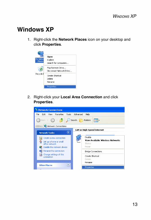
Windows XP
1. Right-click the Network Places icon on your desktop and click Properties.
2. Right-click your Local Area Connection and click Properties.

CONFIGURING YOUR IP ADDRESS
14
3. Click Internet Protocol TCP/IP and click Properties.

WINDOWS XP
15
4. Select the Use the following IP Address option and insert 192.168.2.x (where x is 2~24, 26~254) for the IP address. Specify the default gateway and DNS server as indicated by your network administrator or Internet Service Provider.
5. Click OK and click Close to continue and save the changes.

16
WEB MANAGEMENT
Browser Configuration
Confirm that your browser is configured for a direct connection to the Internet using the Ethernet cable that is installed in the computer.
Disable Proxy Connection
You will also need to verify that the HTTP Proxy feature of your web browser is disabled. This is so that your web browser will be able to view the SMCWEBT-G configuration screens. The following steps are for Internet Explorer. Determine which browser you use and follow the appropriate steps.
Internet Explorer (5.5 or above) in Microsoft Windows 1. Open Internet Explorer. Click Tools, and then select Internet
Options.
2. In the Internet Options window, click the Connections tab.
3. Click the LAN Settings button.
4. Clear all the check boxes and click OK to save these LAN settings changes.
5. Click OK again to close the Internet Options window.
Internet Explorer in Macintosh1. Open Internet Explorer. Click Explorer/Preferences.
2. In the Internet/Explorer/Preferences window, under Network, select Proxies.
3. Uncheck all check boxes and click OK.

NAVIGATING THE WEB BROWSER INTERFACE
17
Navigating the Web Browser Interface
The Wireless AP’s management interface consists of Setup Wizard, Home Network Settings, a Security section and Advanced Settings. Use the web management interface to define system parameters, manage and control the Wireless AP, or monitor network conditions. The following table outlines the selections available from this program.
Making Configuration Changes
Configurable parameters have a dialog box or a drop-down list. Once a configuration change has been made on a screen, be sure to click the SAVE SETTINGS button at the bottom of the screen to enable the new setting.
Menu DescriptionSetup Wizard Use the Setup Wizard for quick and easy configuration of your
Internet connection and basic LAN settings. Go to “Setup Wizard” on page 19 for detailed information.
Home Network Settings
Use the Home Network Settings section to configure your LAN, WAN and wireless settings. Go to “Home Network Settings” on page 25 for more information.
Status Displays WAN/LAN connection status, firmware and hardware version numbers, and security log information.
Network Settings
Sets the TCP/IP configuration of the Wireless AP’s LAN interface and DHCP setup.
Wireless Configures the network operation mode and the wireless channel.
Security Sets SSID, and security encryption for wireless communications.Controls access to your network clients based on the MAC (Media Access Control) address of the client machine.Go to “Security” on page 32.
Advanced Settings
Advanced Settings supports more advanced functions. Go to “Advanced Settings” on page 38.
Maintenance Contains options to backup and restore the current configuration, restore all configuration settings to the factory defaults, update system firmware, or reset the system
System Sets the password for administrator access
WEB MANAGEMENT
18
Note: To ensure proper screen refresh after a command entry, ensure that Internet Explorer 5.5 is configured as follows: Under the menu Tools/Internet Options/General/Temporary Internet Files/Settings, the setting for Check for newer versions of stored pages should be Every visit to the page.
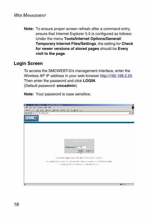
Login Screen
To access the SMCWEBT-G’s management interface, enter the Wireless AP IP address in your web browser http://192.168.2.25Then enter the password and click LOGIN. (Default password: smcadmin)
Note: Your password is case sensitive.

SETUP WIZARD
19
Setup Wizard
Getting StartedClick on the SETUP WIZARD button of the left-hand main menu. The first item in the Setup Wizard is Getting Started.
Simply click NEXT to proceed to the following screen and configure your wireless settings for your Wireless AP.
WEB MANAGEMENT
20
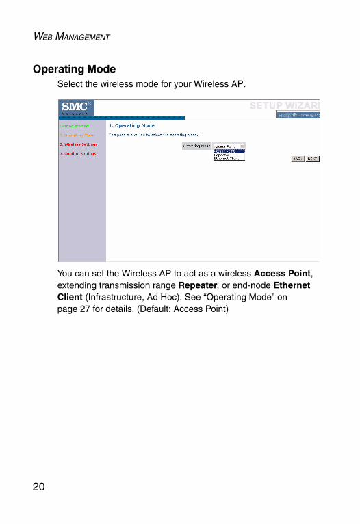
Operating ModeSelect the wireless mode for your Wireless AP.
You can set the Wireless AP to act as a wireless Access Point, extending transmission range Repeater, or end-node Ethernet Client (Infrastructure, Ad Hoc). See “Operating Mode” on page 27 for details. (Default: Access Point)
SETUP WIZARD
21
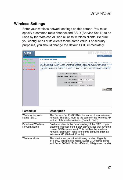
Wireless SettingsEnter your wireless network settings on this screen. You must specify a common radio channel and SSID (Service Set ID) to be used by the Wireless AP and all of its wireless clients. Be sure you configure all of its clients to the same value. For security purposes, you should change the default SSID immediately.
Parameter DescriptionWireless Network Name (SSID)
The Service Set ID (SSID) is the name of your wireless network. The SSID must be the same on the Wireless AP and all of its wireless clients. (Default: SMC)
Broadcast Wireless Network Name
Enable or disable the broadcasting of the SSID. If you disable broadcast of the SSID, only devices that have the correct SSID can connect. This nullifies the wireless network “discovery” feature of some products such as Windows XP. (Default: Enable)
Wireless Mode This device supports the following modes: 11g only, 11b only, 11b/g mixed mode, Super G-Dynamic Turbo and Super G-Static Turbo. (Default: 11b/g mixed mode)

WEB MANAGEMENT
22
Super G
Atheros’ Super G is a series of intelligent mechanisms that engage when additional bandwidth is available and/or needed. It increases the actual end user throughput of an 802.11a/b/g network. These features include bursting, compression, fast frames and Dynamic and Static Turbo. These features are described briefly below.
Super G Feature Summary
Wi-Fi Channel Number
The radio channel used by the Wireless AP and its clients to communicate with each other. This channel must be the same on the Wireless AP and all of its wireless clients.The Wireless AP will automatically assign itself a radio channel, or you may select one manually. (Default: 6)
Extend Range Increases the range of the Wireless AP. (Default: Disable)
Feature Characteristics BenefitBursting • More data frames per given
time period• Standards-based• Relevant to STA
• Increase throughput via overhead reduction
• 802.11e subset• Advantage applies to any AP
Compression • Real-time hardware data compression
• Standards-based Lempel-Ziv-Welch compression method
• Increased data throughput using compressed frames
• No impact on host processor
Fast Frames • Utilizes frame aggregation and timing modifications
• Increases throughput by transmitting more data per frame
Parameter Description
SETUP WIZARD
23
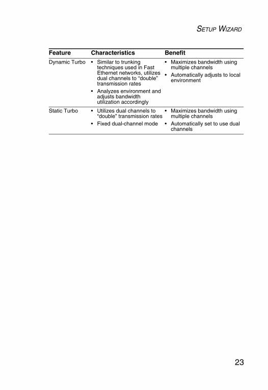
Dynamic Turbo • Similar to trunking techniques used in Fast Ethernet networks, utilizes dual channels to “double” transmission rates
• Analyzes environment and adjusts bandwidth utilization accordingly
• Maximizes bandwidth using multiple channels
• Automatically adjusts to local environment
Static Turbo • Utilizes dual channels to “double” transmission rates
• Fixed dual-channel mode
• Maximizes bandwidth using multiple channels
• Automatically set to use dual channels
Feature Characteristics Benefit
WEB MANAGEMENT
24
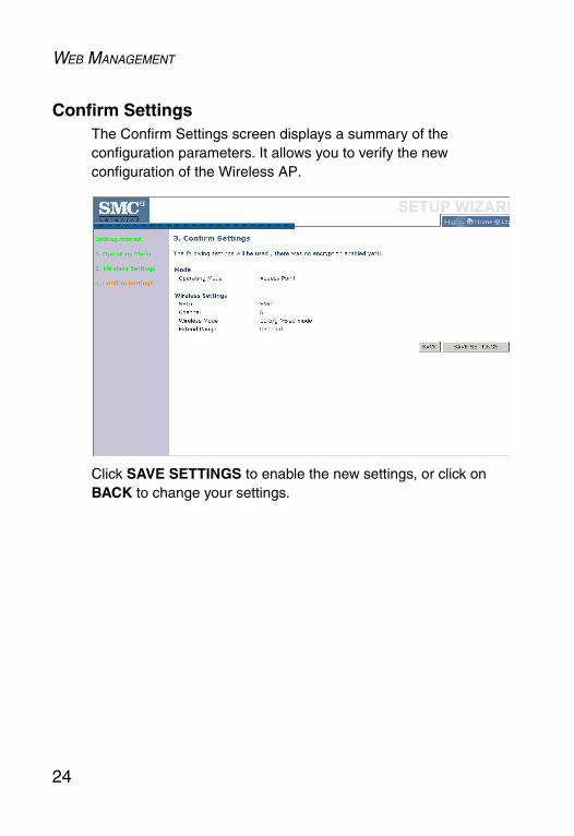
Confirm SettingsThe Confirm Settings screen displays a summary of the configuration parameters. It allows you to verify the new configuration of the Wireless AP.
Click SAVE SETTINGS to enable the new settings, or click on BACK to change your settings.

HOME NETWORK SETTINGS
25
Home Network Settings
Clicking the Home icon at any time, returns you to this home page. The Main Menu links are used to navigate to other menus that display configuration status and parameters.
Status
The Status screen shows LAN/wireless connection status, firmware, and hardware version numbers of the SMCWEBT-G.

WEB MANAGEMENT
26
Network Settings
The AP IP Address field allows you to configure the network IP address of the Wireless AP. The default network settings for the Wireless AP are:
IP Address: 192.168.2.25Subnet Mask: 255.255.255.0
If your Internet Service Provider has assigned a fixed IP address, enter the assigned IP address, subnet mask and gateway IP address for the SMCWEBT-G.
You may need a fixed address if you want to provide Internet services, such as a web server or FTP server.

HOME NETWORK SETTINGS
27
WirelessOperating Mode
This Wireless AP may be set to Access Point, Repeater, or Ethernet Client (Infrastructure, Ad Hoc). (Default: Access Point)
Notes: 1. After you choose the operation mode for the SMCWEBT-G, be sure to click the SAVE SETTINGS button to enable the new setting.
2. The Wireless AP will automatically reboot enabling your new settings.
These modes are described below:
• Access Point – If the SMCWEBT-G is in Access Point mode, you must specify a common radio channel and SSID (Service Set ID) to be used by the Wireless AP and all of your wireless clients. Be sure you configure all of your clients to the same values.

WEB MANAGEMENT
28
• Repeater – In Repeater mode, the radio channel and SSID (Service Set ID) of the SMCWEBT-G must be set to the same values as those of the access point with which the Wireless AP is associated.
• Ethernet Client (Infrastructure, Ad Hoc) – To configure the SMCWEBT-G as an Ethernet Client, all you need to do is click on the provided Scan button and the Activate check box to associate with the selected access point.
HOME NETWORK SETTINGS
29
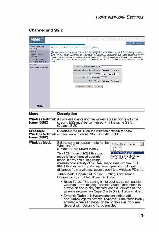
Channel and SSID
Menu DescriptionWireless Network Name (SSID)
All wireless clients and the wireles access points within a specific ESS must be configured with the same SSID. (Default: SMC)
Broadcast Wireless Network Name (SSID)
Broadcast the SSID on the wireless network for easy connection with client PCs. (Default: Enable)
Wireless Mode Set the communication mode for the Wireless AP. (Default: 11b/g Mixed Mode)The 802.11g and 802.11b mixed mode is an enhanced operation mode. It provides a long range wireless connectivity of 328 feet associated with the IEEE 802.11b standards by offering faster speeds and longer distances from a wireless access point to a wireless PC card.Turbo Mode: Capable of Packet Bursting, FastFrames, Compression, and Static/Dynamic Turbo.
• Static Turbo: This setting is not backwards compatible with non-Turbo (legacy) devices. Static Turbo mode is always on and is only enabled when all devices on the wireless network are SuperG with Static Turbo enabled.
• Dynamic Turbo: It is backwards compatible with non-Turbo (legacy) devices. Dynamic Turbo mode is only enabled when all devices on the wireless network are SuperG with Dynamic Turbo enabled.
WEB MANAGEMENT
30
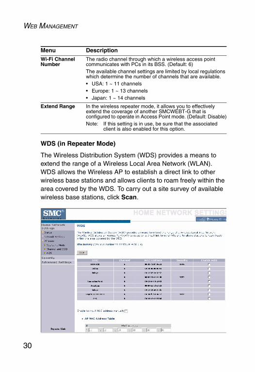
WDS (in Repeater Mode)
The Wireless Distribution System (WDS) provides a means to extend the range of a Wireless Local Area Network (WLAN). WDS allows the Wireless AP to establish a direct link to other wireless base stations and allows clients to roam freely within the area covered by the WDS. To carry out a site survey of available wireless base stations, click Scan.
Wi-Fi Channel Number
The radio channel through which a wireless access point communicates with PCs in its BSS. (Default: 6)The available channel settings are limited by local regulations which determine the number of channels that are available.• USA: 1 ~ 11 channels• Europe: 1 ~ 13 channels• Japan: 1 ~ 14 channels
Extend Range In the wireless repeater mode, it allows you to effectively extend the coverage of another SMCWEBT-G that is configured to operate in Access Point mode. (Default: Disable)Note: If this setting is in use, be sure that the associated
client is also enabled for this option.
Menu Description
HOME NETWORK SETTINGS
31
• Enable to input MAC address manually (Default: Disable) - Up to 4 WDS links can be set by specifying their wireless MAC addresses in the AP MAC Address Table.
Parameter DescriptionSSID The Service Set ID (SSID) is the name of your wireless
network. The SSID must be the same on the Wireless AP and all of its wireless clients.
Channel This device supports the following modes 11g only, 11b only, 11b/g mixed mode, Super G-Dynamic Turbo and Super G-Static Turbo.
MAC Address The media access control address (MAC address) is a unique identifier attached to each wireless base station.
Security Displays the security mechanism in use.
Enable WDS Enables the WDS feature. When enabled, up to 4 WDS links can be set by clicking on the check box. Make sure the same channel is in use on all devices. (Default: Disable)

WEB MANAGEMENT
32
SecurityWireless
Wireless Encryption
If you are transmitting sensitive data across wireless channels, you should enable Wi-Fi Protected Access (WPA/WPA2) or Wired Equivalent Privacy (WEP) encryption. Encryption security requires you to use the same protocol set (WPA/WPA2 or WEP) and encryption/decryption keys for the Wireless AP and all of your wireless clients.
For a more secure network, the Wireless AP can implement one of the following security mechanisms:
“WEP” on page 34
“WPA/WPA2” on page 36
SECURITY
33
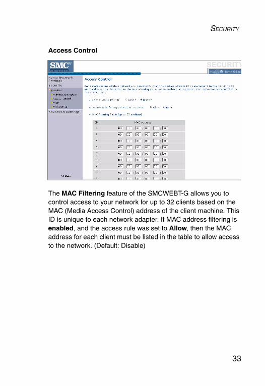
Access Control
The MAC Filtering feature of the SMCWEBT-G allows you to control access to your network for up to 32 clients based on the MAC (Media Access Control) address of the client machine. This ID is unique to each network adapter. If MAC address filtering is enabled, and the access rule was set to Allow, then the MAC address for each client must be listed in the table to allow access to the network. (Default: Disable)

WEB MANAGEMENT
34
WEP
If you are transmitting sensitive data across wireless channels, you should enable Wired Equivalent Privacy (WEP) encryption.
Encryption requires you to use the same set of encryption/decryption keys for a wireless access point and all of its wireless clients. The SMCWEBT-G supports shared key encryption with key lengths of the 64-bit standard and 128-bit industry standard.
WEP mode: You can choose 64-bit or 128-bit encryption.
Key Entry Method: Set your key entry to Hex or ASCII.

SECURITY
35
Encryption Keys
You may manually enter the keys or automatically generate encryption keys. To manually configure the keys, enter 10 digits for each 64-bit key, or enter 26 digits for the single 128-bit key. (A hexadecimal digit is a number or letter in the range 0-9 or A-F.) For automatic 64-bit security, check the box of Passphrase, enter a passphrase and click SAVE SETTINGS.
Four keys will be generated. Choose a key ID (1-4) from the drop-down list or accept the default key.
• 64-Bit Manual Entry
Key 1~4 - Each Key ID contains 10 HEX digits.
• 128-Bit Manual Entry
Key ID contains 26 HEX digits.
Note that Wired Equivalent Privacy (WEP) protects data transmitted between wireless nodes, but does not protect any transmissions over your wired network or over the Internet.
Note: The Wireless AP will automatically reboot enabling your new settings.

WEB MANAGEMENT
36
WPA/WPA2
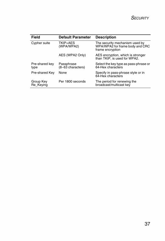
Wi-Fi Protected Access (WPA)/Wi-Fi Protected Access 2 (WPA2) combines Temporal Key Integrity Protocol (TKIP) and Advanced Encryption Standard (AES) mechanisms. It provides dynamic key encryption and mutual authentication service. With TKIP, WPA/WPA2 uses 48-bit initialization vectors, calculates an 8-byte message integrity code, and generates an encryption key periodically. For authentication, it allows you to use Pre-shared Key (PSK) authentication among users in a SOHO network.
Notes: 1. WPA2 is backwords-compatible with WPA.
2. The Wireless AP will automatically reboot enabling your new settings.
SECURITY
37
Field Default Parameter DescriptionCypher suite TKIP+AES
(WPA/WPA2)The security mechanism used by WPA/WPA2 for frame body and CRC frame encryption
AES (WPA2 Only) AES encryption, which is stronger than TKIP, is used for WPA2.
Pre-shared key type
Passphrase (8~63 characters)
Select the key type as pass-phrase or 64-Hex characters
Pre-shared Key None Specify in pass-phrase style or in 64-Hex characters
Group Key Re_Keying
Per 1800 seconds The period for renewing the broadcast/multicast key
WEB MANAGEMENT
38
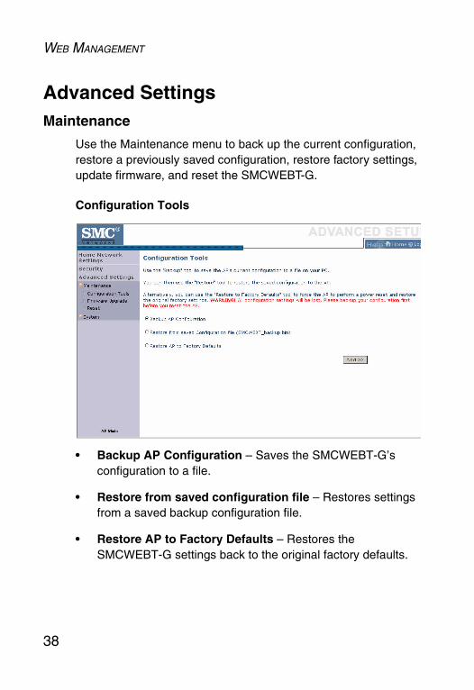
Advanced SettingsMaintenance
Use the Maintenance menu to back up the current configuration, restore a previously saved configuration, restore factory settings, update firmware, and reset the SMCWEBT-G.
Configuration Tools
• Backup AP Configuration – Saves the SMCWEBT-G’s configuration to a file.
• Restore from saved configuration file – Restores settings from a saved backup configuration file.
• Restore AP to Factory Defaults – Restores the SMCWEBT-G settings back to the original factory defaults.

ADVANCED SETTINGS
39
Firmware Upgrade
Use this screen to update the firmware to the latest version. Download the upgrade file from the web site and save it to your hard drive. Click Browse to look for the previously downloaded file. Click BEGIN UPGRADE.
Check the Status screen INFORMATION section to confirm that the upgrade process was successful.
WEB MANAGEMENT
40
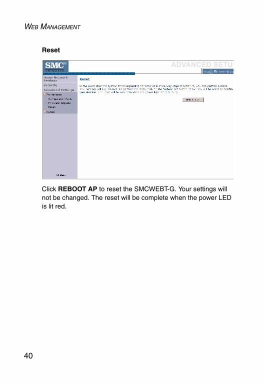
Reset
Click REBOOT AP to reset the SMCWEBT-G. Your settings will not be changed. The reset will be complete when the power LED is lit red.

ADVANCED SETTINGS
41
System
Password Settings
Use this menu to restrict access based on a password. (Default: smcadmin). For security reasons, you should change the default password before exposing the SMCWEBT-G to the Internet.
Passwords can contain from 3 to 12 alphanumeric characters and are case sensitive.
Enter a maximum Idle Time Out (in minutes) to define a maximum period of time for which the login session is maintained during inactivity. If the connection is inactive for longer than the maximum idle time, it will be logged out, and you have to log in to the web management system again. (Default: 10 minutes)

42
NETWORK CONFIGURATION
AND PLANNING
The Wireless Solution supports a stand-alone wireless network configuration, as well as an integrated configuration with 10 Mbps Ethernet LANs. For a list of the maximum distances between the AP/Bridge and wireless clients, refer to page 47.
The wireless network cards and adapters can be configured as:
• Ad hoc – for small departmental or SOHO LANs• Infrastructure – for enterprise LANs
Network Topologies
Ad Hoc Wireless LAN
An ad hoc wireless LAN consists of a group of computers, each equipped with a wireless adapter or SMCWEBT-G Ethernet Client, connected via radio signals as an independent wireless LAN. Computers in a specific ad hoc wireless LAN must be configured to the same radio channel.
An ad hoc wireless LAN can be used for a small branch office or SOHO operation.

NETWORK CONFIGURATION AND PLANNING
43
Infrastructure Wireless LAN
An integrated wired and wireless LAN is called an infrastructure configuration. A Basic Service Set (BSS) consists of a group of wireless PC users, and an access point that is directly connected to the wired LAN. Each wireless PC in this BSS can talk to any computer in its wireless group via a radio link, or access other computers or network resources in the wired LAN infrastructure via the access point.
The infrastructure configuration permits wireless clients to access the wired LAN and also increases the effective wireless transmission range for wireless clients as their signal can be passed through multiple access points.
A wireless infrastructure can be used for access to a central database, or for connection between mobile workers, as shown in the following figure.
NETWORK CONFIGURATION AND PLANNING
44
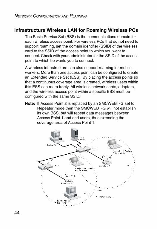
Infrastructure Wireless LAN for Roaming Wireless PCsThe Basic Service Set (BSS) is the communications domain for each wireless access point. For wireless PCs that do not need to support roaming, set the domain identifier (SSID) of the wireless card to the SSID of the access point to which you want to connect. Check with your administrator for the SSID of the access point to which he wants you to connect.
A wireless infrastructure can also support roaming for mobile workers. More than one access point can be configured to create an Extended Service Set (ESS). By placing the access points so that a continuous coverage area is created, wireless users within this ESS can roam freely. All wireless network cards, adapters, and the wireless access point within a specific ESS must be configured with the same SSID.
Note: If Access Point 2 is replaced by an SMCWEBT-G set to Repeater mode then the SMCWEBT-G will not establish its own BSS, but will repeat data messages between Access Point 1 and end users, thus extending the coverage area of Access Point 1.
NETWORK CONFIGURATION AND PLANNING
45
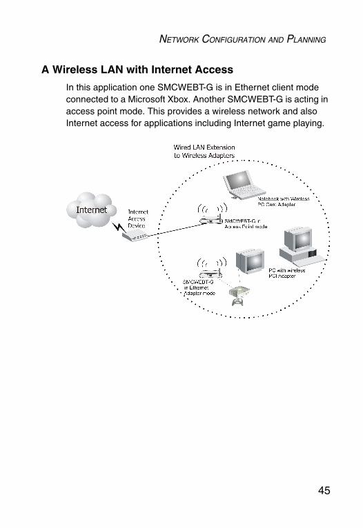
A Wireless LAN with Internet Access
In this application one SMCWEBT-G is in Ethernet client mode connected to a Microsoft Xbox. Another SMCWEBT-G is acting in access point mode. This provides a wireless network and also Internet access for applications including Internet game playing.

46
TROUBLESHOOTING
Check the following items before you contact technical support.
1. If mobile users do not have roaming access to the SMCWEBT-G:
Make sure that all the SMCWEBT-Gs and stations in the ESS in which the WLAN mobile users can roam are configured to the same WEP setting, SSID, and authentication algorithm.
2. If the management utility cannot connect to the SMCWEBT-G:
Check that your local IP address settings conform to the SMCWEBT-G settings.
3. If you forgot your password or your SMCWEBT-G has locked up, you can reset it to factory defaults by performing the following steps:
• Use a pin to push in the RELOAD button for over 8 seconds. This button is located on the bottom of the SMCWEBT-G.
• The SMCWEBT-G will begin to load the default settings.
• The SMCWEBT-G will restart with the factory default settings.

MAXIMUM DISTANCE TABLE
47
Maximum Distance Table
Important Notice
Maximum distances posted below are actual tested distance thresholds. However, there are many variables such as barrier composition and construction and local environmental interference that may impact your actual distances and cause you to experience distance thresholds far lower than those posted below.
Notes: 1. Outdoor Environment: A line-of-sight environment with no interference or obstruction between the Wireless AP and clients.
2. Indoor Environment: A typical office or home environment with floor to ceiling obstructions between the Wireless AP and clients.
802.11b Wireless Distance Table
Speed and Distance RangesEnvironment 11 Mbps 5.5 Mbps 2 Mbps 1 Mbps
Outdoors1 300 m 984 ft
465 m 1525 ft
500 m 1639 ft
515 m 1689 ft
Indoors2 60 m 197 ft
70 m 230 ft
83 m 272 ft
85 m 279 ft
802.11g Wireless Distance Table
Speed and Distance RangesEnvironment 54
Mbps48
Mbps36
Mbps24
Mbps18
Mbps12
Mbps11
Mbps9
Mbps6
Mbps5
Mbps2
Mbps1
Mbps
Outdoors1 82 m 269 ft
100 m 328 ft
300 m984 ft
330 m1082 ft
350 m1148 ft
450 m1475 ft
470 m 1541 ft
485 m 1590 ft
495 m 1623 ft
510 m 1672 ft
520 m 1705 ft
525 m 1722 ft
Indoors2 20 m66 ft
25 m82 ft
35 m115 ft
43 m141 ft
50 m164 ft
57 m187 ft
66 m216 ft
71 m233 ft
80 m262 ft
85 m279 ft
90 m295 ft
93 m305 ft

48
SPECIFICATIONS
StandardsIEEE 802.3 10BASE-T Ethernet IEEE 802.3u 100BASE-TX Fast EthernetIEEE 802.11bIEEE 802.11g
Data Rates1/2/5.5/6/9/11/12/18/24/36/48/54 Mbps
Frequency BandIEEE 802.11b/g Radio: 2.4 GHz
USA - FCC 2412~2462 MHz (Ch1~Ch11)Canada - IC2412~2462 MHz (Ch1~Ch11)Europe - ETSI 2412~2472 MHz (Ch1~Ch13)Japan - STD-T66/STD-332412~2484 MHz (Ch1~Ch14)
Modulation TypeOFDM, CCK Operating ChannelsIEEE 802.11b/g compliant
11 channels (US, Canada)13 channels (ETSI)14 channels (Japan)
AntennaOne detachable external antenna with RP-SMA connector:
1.5 dBi omni-directional dipole One internal 2 dBi dipole antenna

SPECIFICATIONS
49
Sensitivity Modulation Rate
Modulation Rate Receive Sensitivity Typical (dBm)
802.11b - 1 Mbps -90
802.11b - 2 Mbps -88
802.11b - 5.5 Mbps -85
802.11b- 11 Mbps -82
802.11g - 6 Mbps -88
802.11g - 9 Mbps -87
802.11g - 12 Mbps -84
802.11g - 18 Mbps -82
802.11g - 24 Mbps -79
802.11g - 36 Mbps -75
802.11g - 48 Mbps -68
802.11g - 54 Mbps -68
SPECIFICATIONS
50
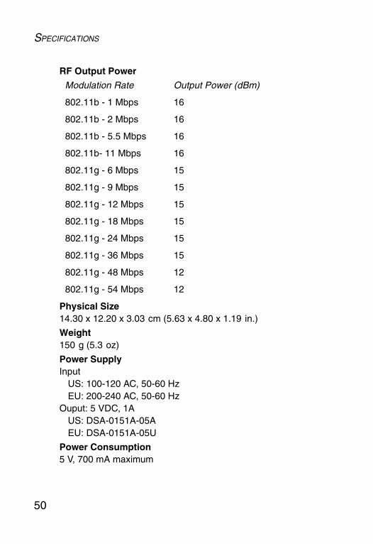
RF Output Power
Physical Size14.30 x 12.20 x 3.03 cm (5.63 x 4.80 x 1.19 in.)
Weight150 g (5.3 oz)
Power SupplyInput
US: 100-120 AC, 50-60 Hz EU: 200-240 AC, 50-60 Hz
Ouput: 5 VDC, 1AUS: DSA-0151A-05AEU: DSA-0151A-05U
Power Consumption5 V, 700 mA maximum
Modulation Rate Output Power (dBm)
802.11b - 1 Mbps 16
802.11b - 2 Mbps 16
802.11b - 5.5 Mbps 16
802.11b- 11 Mbps 16
802.11g - 6 Mbps 15
802.11g - 9 Mbps 15
802.11g - 12 Mbps 15
802.11g - 18 Mbps 15
802.11g - 24 Mbps 15
802.11g - 36 Mbps 15
802.11g - 48 Mbps 12
802.11g - 54 Mbps 12

SPECIFICATIONS
51
TemperatureOperating: 0 to 40 °C (32 to 104 °F)Storage: -40 to 70 °C (-40 to 158 °F)
Humidity5% to 95% (non-condensing)
LED IndicatorsPower, Ethernet Link/Activity,Wireless Activity (TX/RX)
Network ManagementWindows 98SE/Me/2000/XP SNMP Management Utility
Operating System CompatibilityWindows 98SE/Me/2000/XP
Supported ProtocolTCP/IP, IPX
Encryption64-bit/128-bit WEPWPA/WPA2
CompliancesCE MarkEN55022 Class BEN55024IEC 61000-42/3/4/6/11
EmissionsFCC Part 15 Class BETSI 300.328ARIB STD33 and T66

SPECIFICATIONS
52

