iris segmentation using geodesic active contours shahrossgaciris_tifs2009
DESCRIPTION
An iris recognition systemTRANSCRIPT

824 IEEE TRANSACTIONS ON INFORMATION FORENSICS AND SECURITY, VOL. 4, NO. 4, DECEMBER 2009
Iris Segmentation Using Geodesic Active ContoursSamir Shah and Arun Ross, Member, IEEE
Abstract—The richness and apparent stability of the iris texturemake it a robust biometric trait for personal authentication. Theperformance of an automated iris recognition system is affected bythe accuracy of the segmentation process used to localize the irisstructure. Most segmentation models in the literature assume thatthe pupillary, limbic, and eyelid boundaries are circular or ellip-tical in shape. Hence, they focus on determining model parame-ters that best fit these hypotheses. However, it is difficult to seg-ment iris images acquired under nonideal conditions using suchconic models. In this paper, we describe a novel iris segmentationscheme employing geodesic active contours (GACs) to extract theiris from the surrounding structures. Since active contours can 1)assume any shape and 2) segment multiple objects simultaneously,they mitigate some of the concerns associated with traditional irissegmentation models. The proposed scheme elicits the iris texturein an iterative fashion and is guided by both local and global prop-erties of the image. The matching accuracy of an iris recognitionsystem is observed to improve upon application of the proposedsegmentation algorithm. Experimental results on the CASIA v3.0and WVU nonideal iris databases indicate the efficacy of the pro-posed technique.
Index Terms—Geodesic active contours (GACs), iriscodes, irisrecognition, iris segmentation, level sets, snakes.
I. INTRODUCTION
T HE iris is an internal organ of the eye that is located justbehind the cornea and in front of the lens. Its function is to
control the size of the pupil, which in turn regulates the amountof light entering the pupil and impinging the retina. Flom andSafir [1] have postulated that “the basic, significant features ofthe iris remain extremely stable and do not change over a periodof many years” (this claim has been challenged in the recentliterature). They state that every iris is unique and no two indi-viduals have the same iris compositions. Indeed, the two iridesof an individual have been observed to be different in their intri-cate texture structure. Hence, the iris is considered to be a robustand unique biometric with a very low False Accept Rate (FAR).Large-scale authentication experiments have confirmed this no-tion further underscoring the relevance of this biometric trait indistinguishing individuals [2], [3].
Manuscript received June 29, 2008; revised July 11, 2009. First publishedSeptember 29, 2009. This work was supported in part by the Center for Identi-fication Technology Research (CITeR) at West Virginia University and in partby the NSF CAREER Award IIS 0642554. A preliminary version of this workwas presented at the 2006 Biometrics Symposium, Baltimore, MD, Sep. 2006.The associate editor coordinating the review of this manuscript and approvingit for publication was Dr. Tieniu Tan.
S. Shah is with the Iris Technology Division, LG Electronics USA Inc., Cran-bury, NJ 08512 USA (e-mail: [email protected]).
A. Ross is with West Virginia University, Morgantown, WV 26506 USA(e-mail: [email protected]).
Color versions of one or more of the figures in this paper are available onlineat http://ieeexplore.ieee.org.
Digital Object Identifier 10.1109/TIFS.2009.2033225
Fig. 1. Block diagram of an iris recognition system.
Fig. 2. Salient features in the anterior portion of the iris.
The function of an iris recognition system is to extract, rep-resent and compare the textural intricacy present on the surfaceof the iris. Such a system comprises of modules for iris segmen-tation, enhancement, feature extraction (encoding) and featurematching (Fig. 1). The first and, perhaps, the most importantstep in an iris recognition system is iris segmentation or local-ization. Segmentation involves detecting and isolating the irisstructure from an image of the eye. As seen in Fig. 2, the irisprojected onto a 2-D plane appears to be located in the vicinityof the sclera, pupil, and eyelids. Thus, the segmentation processhas to accurately detect boundaries separating the iris from thesecomponents. Apart from estimating the actual shape of the iris,the segmentation routine should detect occlusions due to eye-lashes that can confound the extracted features. Errors in seg-mentation may result in inferior recognition performance dueto inaccurate encoding of the textural content of the iris.
Several iris recognition algorithms have been proposed in theliterature. Daugman [4], [5] uses a texture-based method to en-code irides. Multiscale 2-D Gabor-Wavelet transform is used togenerate a 256-byte iriscode. Hamming distance is then usedas a measure to determine the proximity of two iriscodes. The
1556-6013/$26.00 © 2009 IEEE

SHAH AND ROSS: IRIS SEGMENTATION USING GEODESIC ACTIVE CONTOURS 825
TABLE IEXAMPLES OF A FEW IRIS SEGMENTATION, ENCODING AND MATCHING TECHNIQUES PROPOSED IN THE LITERATURE. OTHER EXAMPLES CAN BE FOUND IN [2]
integro-differential operator, which acts as a circular edge de-tector, is employed for determining the inner and outer bound-aries of the iris as well as the upper and lower eyelids. Wildes[6] uses Laplacian-of-a-Gaussian (LOG) filter to extract featuresfrom the iris image. A Hough transform-based method is usedto segment the iris. Also, the upper and lower boundaries ofthe eyelid are approximated using parabolic curves. Matchingis done using the normalized correlation between the test andtraining images. Masek and Kovesi [7] employ weighted gradi-ents using a combination of Kovesi’s modified canny edge de-tector and the circular Hough-transform to segment the iris. Sev-eral other segmentation schemes proposed in the literature arealso based on the Hough-transform (see, for example, [8]–[14]).Huang et al. [15] first coarsely segment the iris using edge de-tection filters and Hough transform before normalizing it. Thenoise due to eyelids is then localized by the edge informationbased on phase congruency. Abhyankar and Schuckers [16] usetraining based Active Shape Models to segment the iris fromthe sclera. The nonlinear shape of the iris is learned using a fewtraining images. More recently, Daugman [3] designed novelsegmentation and encoding schemes for processing nonidealirides. Hollingsworth [17] illustrated that every iriscode (iristemplate) has some fragile bits. A bit is fragile if it has a signif-icant probability of being a 0 for some images of the iris and 1for other images of the same iris. If the fragile bits were masked,the performance of the iris recognition system was observed toincrease. Table I summarizes the segmentation, encoding (i.e.,representation) and matching techniques of a few algorithms de-scribed in the literature.
Most segmentation models in the literature assume that thepupillary, the limbic, and the eyelid boundaries are circular orelliptical in shape. Hence, they focus on determining model pa-rameters that best fit these hypotheses ([4], [6], [10]). Only veryfew algorithms in the literature do not assume circular or ellip-tical boundaries (e.g., see Abhyankar and Schuckers [16] andDaugman [3]). In this paper, a novel geodesic active contour(GAC)-based scheme is employed to accurately determine theboundary of the iris thereby eliciting the shape of its boundary.As the boundary of the iris is not approximated using a circle
or an ellipse in the proposed scheme, the localized iris regionis expected to contain very few noniris pixels. Active Contourshave been extensively used in the field of medical image anal-ysis for segmenting various images like brain MRI images [23]and abdominal CT images [24]. They have also been used in thefield of machine vision [25]. In this paper, their significance inthe context of efficient iris segmentation is demonstrated.
The remainder of the paper is organized as follows. A base-line segmentation, encoding and matching method is describedin Section II. Section III provides an overview of the proposedsegmentation technique based on GACs. The matching per-formance due to this novel scheme is reported in Section IV.Section V concludes the paper.
II. BASELINE IRIS SEGMENTATION, ENCODING,AND MATCHING TECHNIQUE
In order to demonstrate the performance improvementobtained using the proposed algorithm, a baseline segmen-tation, encoding and matching algorithm is first defined.Integro-differential operators, which are a variation of theHough transform, act as circular edge detectors and havebeen previously used to determine the inner and the outerboundaries of the iris. They also have been used to deter-mine the elliptical boundaries of the lower and the uppereyelids. An integro-differential operator can be defined as
where is the image, is the radius of the pupil oriris, its center and is the Gaussian smoothingfunction with scale . Thus, the integro-differential operatorsearches for a circular boundary with radius and center
such that the change in radial pixel intensity across theboundary is maximum. The eyelids can be detected in a similarfashion by performing the integration on an elliptical boundaryrather than a circular one. The output of the segmentationprocess is a binary mask that indicates the iris and nonirispixels in the image.
Iris segmentation is followed by a normalization scheme togenerate a fixed dimension feature vector that lends itself tomatching. Each point in the domain is mapped to a pair

826 IEEE TRANSACTIONS ON INFORMATION FORENSICS AND SECURITY, VOL. 4, NO. 4, DECEMBER 2009
Fig. 3. Real part of 2-D Gabor wavelet filters.
of polar coordinates (like the rubber sheet model pro-posed by Daugman [4]). This results in a fixed size unwrappedrectangular iris image. Gabor filters are then used to extract thetextural information from the unwrapped iris (encoding). A 2-DGabor filter over an image domain is given by
wherespecifies the center of the Gaussian filter, and
are the width and length of the filter, specify themodulation with frequency and orientation
.1 The prominence of the iris texturechanges as one moves away from the pupil. Hence, a set ofthree Gabor filters with different scales and frequency but thesame orientation are applied to different regions of the“normalized” iris as shown in Fig. 3. The filtering results incomplex-valued phase information. This phase information isquantized into four quadrants in the complex plane resultingin two bits denoting the real and complex parts of the phasorresponse at a pixel. The resulting binary feature vector iscalled an iriscode. The difference between two such iriscodesis measured using the Hamming distance which is a measureof the number of different bits between the two iriscodes. TheHamming distance is a dissimilarity score and is calculatedusing the bits corresponding to the iris pixels by utilizing thebinary masks generated in the segmentation process. Let and
be the two iriscodes to be compared, and and be theirrespective masks. The Hamming distance (HD) is calculated asfollows:
where the XOR operator, , detects the disagreement betweenthe corresponding bits in the iriscodes, the AND operator, , en-sures that the Hamming distance is calculated using only thebits generated from the true iris region and the operatorcomputes the norm of the bit vector. Ideally, the Hamming dis-tance between two images of the same iris will be 0 (genuinescore) and that between two images of different irides will be(0.5) (impostor score).
III. IRIS SEGMENTATION USING GACS
The iris localization procedure can be broadly divided intotwo stages: (a) pupil segmentation and (b) iris segmentation.
1One could use a ��� Gabor filter instead of a ��� Gabor filter since thethe iris information does not change radially as much as it does angularly [26].
Fig. 4. Pupil binarization. (a) Image of an eye with dark eyelashes. (b) Thresh-olded binary iris image.
Fig. 5. Pupil Segmentation. (a) 2-D Median filtered binary iris image. (b)Traced boundaries of all the remaining objects in the binary image (shown ingray color). (c) Fitting circle on all potential regions where the pupil might bepresent (shown in gray).
A. Pupil Segmentation
To detect the pupillary boundary, the eye image is firstsmoothed using a 2-D median filter and the minimum pixelvalue is determined. The iris is then binarized using athreshold value . Fig. 4(b) shows an iris image afterbinarization. As expected, apart from the pupil, other darkregions of the eye (e.g., eyelashes) fall below this thresholdvalue. A 2-D median filter is then applied on the binary imageto discard the relatively smaller regions associated with theeyelashes. This reduces the number of candidate iris pixelsdetected as a consequence of thresholding as seen in Fig. 5(a).Based on the median-filtered binary image, the exterior bound-aries of all the remaining objects are traced as shown inFig. 5(b). Generally, the largest boundary of the remaining

SHAH AND ROSS: IRIS SEGMENTATION USING GEODESIC ACTIVE CONTOURS 827
Fig. 6. Pupil segmentation. (a) Image of an eye with dark eyelashes. (b) Seg-mented pupil (shown in blue).
regions of the eye corresponds to the pupil. However, whenthe pupil is constricted, it is very likely that the boundary ofthe detected region corresponding to the eyelashes is largerthan that of the pupil. So a circle-fitting procedure is executedon all detected regions. The equation of a circle is given by
where represent the co-ordinates of a point on the circle. The coordinates of the centercan be computed as and the radiusas . Let be
points traversed by the circle, and let
Then the equation of the circle may be written as .Thus, to estimate the radius and the center of the circle, the ex-pression needs to be solved. Since is not asquare matrix, its inverse is computed using the least squarescriterion.2 Fig. 5(c) demonstrates the circles fitted through allthe detected regions. Finally, the circle whose circumferencecontains the maximum number of black pixels is deemed to bethe detected pupil. Regions with diameters more than half theimage size are not considered. Fig. 6 shows an iris image con-taining dark eyelashes and the correctly segmented pupil usingthe aforementioned algorithm. Sometimes, specular reflectionscan occur near the boundary of the pupil that may confoundthe pupil segmentation procedure. For example, in Fig. 7, itis obvious that the pupil is under-segmented due to the pres-ence of the specular reflection near the pupil boundary. Hence,if specular reflection (bright spots in an image) is detected in thevicinity of the pupil, it is “inpainted” using the surrounding in-formation [27]. Inpainting is a process to fill in the missing por-tions of am image (in our case specular reflections) to improveits integrity [28]. Fig. 8(f) demonstrates that the pupil detectionprocedure is made more robust by inpainting those specular re-flections in the iris image that occur near the pupil boundary.Since the specular reflections are detected by a simple imagethresholding technique, other regions of the eye that are over-exposed to light may also be incorrectly detected. However, in-
2[Online]. Available: http://www.mathworks.com/moler/leastsquares.pdf
painting such regions with the surrounding information will bebeneficial.
Fig. 9 presents other results of the pupil segmentationprocess.
B. Iris Segmentation
To detect the limbic boundary of the iris, a novel schemebased on a level sets representation [29], [25] of the GAC modelis employed. This approach is based on the relation between ac-tive contours and the computation of geodesics (minimal lengthcurves) [30]. The technique is to evolve the contour from in-side the iris under the influence of geometric measures of theiris image. GACs combine the energy minimization approach ofthe classical “snakes” and the geometric active contours basedon curve evolution.
The proposed technique is significantly different from the oneproposed by Daugman [3]. In [3], the active contour is definedas a Fourier boundary approximated using the coefficients of theFourier series. The technique relies on the order of the Fourierseries to approximate the inner and outer boundaries of the iris.Further, the order of the two boundaries is likely to be different(as pointed out in the paper). Thus, selecting the order of theFourier series is an important task.
1) GACs: Let be the curve, that has to gravitate towardthe boundary of any object, at a particular time as shown inFig. 10. The time corresponds to the iteration number. Let bea function defined as a signed distance function from the curve
. Thus, distance of point to the curve .
if is on the curveif is inside the curveif is outside the curve
(1)
is of the same dimension as that of the image thatis to be segmented. The curve is a level set of the func-tion . Level sets are the set of all points in wheresome constant. Thus, is the zeroth level set, isthe first level set and so on. is the implicit representation ofthe curve and is called as the embedding function since itembeds the evolution of . The embedding function evolvesunder the influence of image gradients and regions characteris-tics so that the curve approaches the boundary of the ob-ject. Thus, instead of evolving the parametric curve (e.g.,the Lagrangian approach used in snakes), the embedding func-tion itself is evolved. In our algorithm, the initial curveis assumed to be a circle of radius just beyond the pupillaryboundary. Let the curve be the zeroth-level set of the em-bedding function. This implies that
By the chain rule
i.e.,

828 IEEE TRANSACTIONS ON INFORMATION FORENSICS AND SECURITY, VOL. 4, NO. 4, DECEMBER 2009
Fig. 7. Result of pupil segmentation when inpainting is not used to remove specular reflections. (a) Eye image. (b) Smoothed image. (c) Thresholded binaryimage. (d) 2-D Median filtered image. (e) Undersegmented pupil (shown using blue-colored contour).
Fig. 8. Result of pupil segmentation when inpainting is used to remove specular reflections in the vicinity of the pupil. (a) Eye image. (b) Smoothed image.(c) Inpainted specular reflection in the vicinity of the pupil. (d) Thresholded binary image. (e) 2-D Median filtered image. (f) Segmented pupil (shown usingblue-colored contour).
Fig. 9. Pupil segmentation. (a) Iris image. (b) Thresholded binary image. (c) 2-D Median filtered image. (d) Segmented pupil (shown using blue-colored contour).

SHAH AND ROSS: IRIS SEGMENTATION USING GEODESIC ACTIVE CONTOURS 829
Fig. 10. Curve � evolving towards the boundary of the object.
Splitting the in the normal and tangentialdirections,
Now, since is perpendicular to the tangent to
(2)
The normal component is given by
Substituting this in (2)
Let be a function of the curvature of the curve , stoppingfunction (to stop the evolution of the curve) and the inflationforce (to evolve the curve in the outward direction) such that,
Thus, the evolution equation for such that remains thezeroth level set is given by
(3)
where , the stopping term for the evolution, is an image de-pendant force and is used to decelerate the evolution near theboundaries; is the velocity of the evolution; indicates the de-gree of smoothness of the level sets; and is the curvature ofthe level sets computed as
where is the gradient of the image in the direction; isthe gradient in the direction; is the second-order gradientin the direction; is the second-order gradient in thedirection; and is the second-order gradient, first in thedirection and then in the direction. Equation (3) is the level setrepresentation of the GAC model. This means that the level-set
of is evolving according to
(4)
Fig. 11. Stopping function for the GACs. (a) Original iris image. (b) Stoppingfunction � . (c) Modified stopping function � .
where is the normal to the curve. The first term providesthe smoothing constraints on the level sets by reducing the totalcurvature of the level sets. The second term acts like a bal-loon force [31] and it pushes the curve outward towards the ob-ject boundary. The goal of the stopping function is to slow downthe evolution when it reaches the boundaries. However, the evo-lution of the curve will terminate only when , i.e., near anideal edge. In most images, the gradient values will be differentalong the edge, thus, necessitating different K values. In order tocircumvent this issue, the third geodesic term is nec-essary so that the curve is attracted toward the boundaries (points toward the middle of the boundary). This term makes itpossible to terminate the evolution process even if (a) the stop-ping function has different values along the edges, and (b) gapsare present in the stopping function.
The stopping term used for the evolution of level sets is givenby
(5)
where is the image to be segmented, and and areconstants. As can be seen, this term is not a function of.
2) Iris Segmentation Using GACs: Consider an iris image tobe segmented as shown in Fig. 11(a). The stopping function
obtained from this image is shown in Fig. 11(b) (Inour implementation, for WVU nonideal images, and
). As the pupil segmentation is done prior to segmentingthe iris, the stopping function is modified by deleting thecircular edges because of the pupillary boundary, resulting ina new stopping function . This ensures that the evolvinglevel set is not terminated by the edges of the pupillaryboundary [Fig. 11(c)].
A contour is first initialized near the pupil [Fig. 12(a)]. Theembedding function is initialized as a signed distance functionto which looks like a cone [Fig. 12(b)]. Discretizing

830 IEEE TRANSACTIONS ON INFORMATION FORENSICS AND SECURITY, VOL. 4, NO. 4, DECEMBER 2009
Fig. 12. Contour initialization for iris segmentation. (a) Zeroth level set (initialcontour). (b) Mesh plot of the signed distance function �.
(3) leads to the following equation:
(6)
where is the time step. In our implementation, is set to0.05. The first term on the right-hand side of theabove equation is the velocity term (advection term) and in thecase of iris segmentation, acts as an inflation force. This termcan lead to singularities and, hence, is discretized using upwindfinite differences [32]. The upwind scheme for approximating
is given by
where is the first-order backward difference of in thex-direction; is the first-order forward difference of inthe x-direction; is the first-order backward difference ofin the y-direction; and is the first-order forward differenceof in the y-direction. The second term isa curvature based smoothing term and can be discretized usingcentral differences. In our implementation, andfor all iris images. The third geodesic term isalso discretized using the central differences.
After evolving the embedding function according to (6),the curve starts to grow until it satisfies the stopping criterion de-fined by the stopping function . But at times, the contour con-tinues to evolve in a local region of the iris where the stoppingcriterion is not strong. This leads to overevolution of the con-tour. To avoid it, we minimize the Thin Plate Spline energy ofthe contours. Thin Plate Spline [33] is an interpolation methodthat finds the minimal “bending energy” to pass a smooth sur-face though a set of given points. The name “Thin Plate Splines”can be thought of as a simulation of how a thin metal plate wouldbend if it was forced through some fixed control points. Thus,the thin plate spline energy to pass a smooth surface thoughcoplanar points will be zero where as if the points are nonplanar,the thin plate spline energy will increase with the distance be-tween these points. In this work, Thin Plate Splines are usedfor minimizing the energy of the contour so as to prevent the
contour from evolving in a highly nonuniform manner. Here,the evolving contour can be thought of as the smooth surfacewhich needs to be fitted through the points on the iris boundary.Thus, if all points on the contour lie on a circle, then the thinplate spline energy will be zero; however, if the contour startsevolving nonuniformly, the thin plate spline energy to fit thecontour through these points will start increasing. By computingthe difference in energy between two successive contours, theevolution scheme can be regulated. If the difference betweenthe contours is less than a threshold (indicating that the contourevolution has stopped at most places), then the contour evolu-tion process is stopped. In our implementation, this threshold isset to 1. The evolution of the curve and the corresponding em-bedding functions are illustrated in Fig. 13.
If the Thin Plate Spline energy of the level sets is not mini-mized, the contour might continue evolving if the stopping func-tion does not have a high magnitude. In such cases, the contourwill incorrectly encompass some portion of the sclera inside thefinal contour as shown in Fig. 14(a). Minimizing the thin platespline energy of level sets yields a more precise contour of theiris boundary [Fig. 14(b)].
One important feature of GACs is their ability to handle“splitting and merging” boundaries. This is especially impor-tant in the case of iris segmentation since the radial fibers maybe thick in some portions of the iris, or the crypts present inthe ciliary region may be unusually dark, leading to prominentedges in the stopping function. If the segmentation techniqueis based on parametric curves (e.g., the snakes segmentationtechnique [34]), then the evolution of the curve might terminateat these local minima. However, GACs are able to split at suchlocal minima and merge again. Thus, they are able to effectivelydeal with the problems of local minima thereby ensuring thatthe final contour corresponds to the true iris boundary (Fig. 15).
Since, during the evolution process, the primary interest isonly in the zeroth level set of , the embedding function canbe evolved only in a narrow band around the zeroth level set[25]. This accelerates the evolution procedure dramatically and,hence, the whole localization and normalization process takesless than a second in a C environment. During the evolu-tion process, the contour is evolved around a small narrow bandaround the contour. The evolution process is not uniform acrossthe contour but can vary due to obstacles such as specular reflec-tions, eyelashes, etc. Thus, after a few iterations the embeddingfunction may not remain a signed distance function and will be-come “badly conditioned.” So after every few iterations the em-bedding function is reinitialized by recomputing the embeddingfunction as a signed distance function from the new contour.
The extracted contour is employed to create the binary maskthat is used during the matching of the iriscodes (II). To nor-malize the iris and convert it to a rectangular entity, its radiusand the corresponding center coordinates have to be estimated.If the occlusion due to the upper or lower eyelids is substantial,then a circle that fits all the points on the extracted contour willlie inside the actual boundary of the iris. Thus, only those pointson the contour lying on the boundary of the iris and sclera (asopposed to the iris and the eyelids) should be used to estimatethe radius and center of the iris. To ensure this, six points at

SHAH AND ROSS: IRIS SEGMENTATION USING GEODESIC ACTIVE CONTOURS 831
Fig. 13. Evolution of the GAC during iris segmentation. (a) Iris image withinitial contour. (b) Embedding function � (X and Y axis correspond to the sizeof the iris image and the Z axis represents different level sets). (c), (d), (e),(f) Contours after 600 and 1400 iterations, and their corresponding embeddingfunctions. (g), (h) Final contour after 1800 iterations and the corresponding em-bedding function (contours shown in white).
angles of with respect to thehorizontal axis are selected from the extracted contour and theirmean distance from the center of the pupil is computed. Thisvalue is used as the approximate radius of the iris . A circleis next fitted through all the points on the contour that are withina distance of pixels from the center of the pupil. Thecenter and radius of such a circle is the center and the
Fig. 14. Effect of minimizing the thin plate energy of the level sets on the evo-lution of the GAC. (a) Contour without minimizing the thin plate energy of thelevel sets. (b) Contour obtained by minimizing the thin plate energy of the levelsets (contours shown in white).
Fig. 15. Final contour segmenting the iris. (a) Geodesic contour splitting atvarious local minima. (b) Final contour (contours shown in white).
Fig. 16. Robust estimation of the radius and center of the iris using GAC. (a)and (b) Iris center and radius estimated using Masek’s algorithm. (c) and (d) Iriscenter and radius estimated using GACs (iris radius shown in white).
radius of the iris. Fig. 16 illustrates the radius of the iris de-tected by our approach along with the radius of the iris detectedusing the classical integro-differential operators.
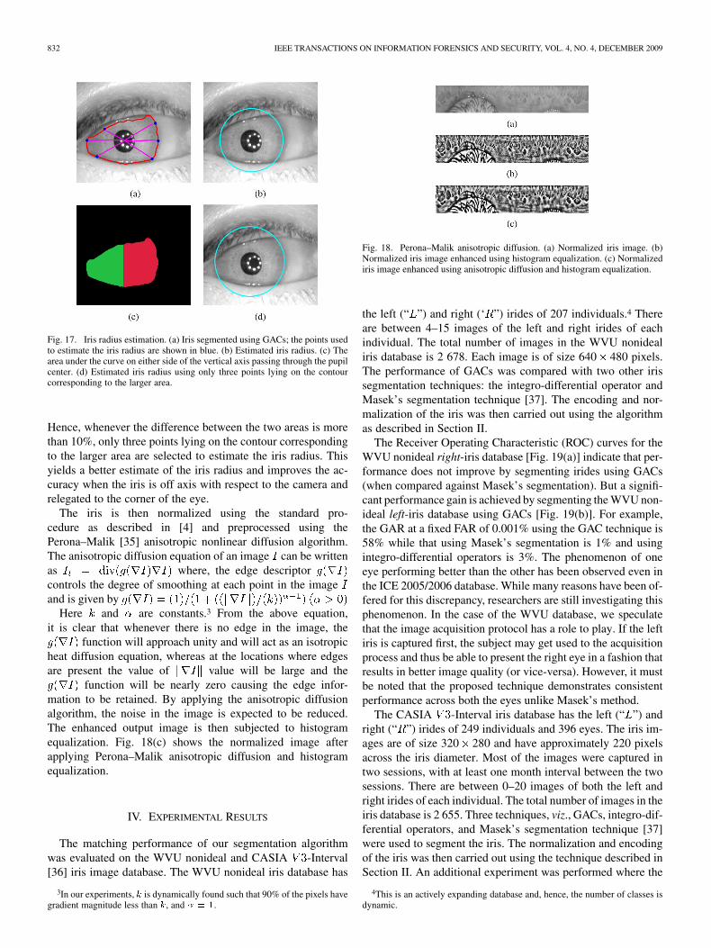
When the iris is detected in the corner of the eye, all six pointschosen to estimate the approximate iris radius may not lie on theiris boundary; instead some may lie on the eyelid. As the eyelidboundary is closer to the center of the pupil, the approximate irisradius is skewed and is smaller than the actual radius [as shownin Fig. 17(a) and (b)].
As can be seen from Fig. 17(c), the area under the segmentediris curve on either side of the vertical axis passing through thepupil is not equal. The region with smaller area corresponds tothe portion where the iris is heavily occluded by the eyelids.
832 IEEE TRANSACTIONS ON INFORMATION FORENSICS AND SECURITY, VOL. 4, NO. 4, DECEMBER 2009
Fig. 17. Iris radius estimation. (a) Iris segmented using GACs; the points usedto estimate the iris radius are shown in blue. (b) Estimated iris radius. (c) Thearea under the curve on either side of the vertical axis passing through the pupilcenter. (d) Estimated iris radius using only three points lying on the contourcorresponding to the larger area.
Hence, whenever the difference between the two areas is morethan 10%, only three points lying on the contour correspondingto the larger area are selected to estimate the iris radius. Thisyields a better estimate of the iris radius and improves the ac-curacy when the iris is off axis with respect to the camera andrelegated to the corner of the eye.
The iris is then normalized using the standard pro-cedure as described in [4] and preprocessed using thePerona–Malik [35] anisotropic nonlinear diffusion algorithm.The anisotropic diffusion equation of an image can be writtenas where, the edge descriptorcontrols the degree of smoothing at each point in the imageand is given by
Here and are constants.3 From the above equation,it is clear that whenever there is no edge in the image, the
function will approach unity and will act as an isotropicheat diffusion equation, whereas at the locations where edgesare present the value of value will be large and the
function will be nearly zero causing the edge infor-mation to be retained. By applying the anisotropic diffusionalgorithm, the noise in the image is expected to be reduced.The enhanced output image is then subjected to histogramequalization. Fig. 18(c) shows the normalized image afterapplying Perona–Malik anisotropic diffusion and histogramequalization.
IV. EXPERIMENTAL RESULTS
The matching performance of our segmentation algorithmwas evaluated on the WVU nonideal and CASIA -Interval[36] iris image database. The WVU nonideal iris database has
3In our experiments, � is dynamically found such that 90% of the pixels havegradient magnitude less than �, and � � �.
Fig. 18. Perona–Malik anisotropic diffusion. (a) Normalized iris image. (b)Normalized iris image enhanced using histogram equalization. (c) Normalizediris image enhanced using anisotropic diffusion and histogram equalization.
the left (“ ”) and right (‘ ”) irides of 207 individuals.4 Thereare between 4–15 images of the left and right irides of eachindividual. The total number of images in the WVU nonidealiris database is 2 678. Each image is of size 640 480 pixels.The performance of GACs was compared with two other irissegmentation techniques: the integro-differential operator andMasek’s segmentation technique [37]. The encoding and nor-malization of the iris was then carried out using the algorithmas described in Section II.
The Receiver Operating Characteristic (ROC) curves for theWVU nonideal right-iris database [Fig. 19(a)] indicate that per-formance does not improve by segmenting irides using GACs(when compared against Masek’s segmentation). But a signifi-cant performance gain is achieved by segmenting the WVU non-ideal left-iris database using GACs [Fig. 19(b)]. For example,the GAR at a fixed FAR of 0.001% using the GAC technique is58% while that using Masek’s segmentation is 1% and usingintegro-differential operators is 3%. The phenomenon of oneeye performing better than the other has been observed even inthe ICE 2005/2006 database. While many reasons have been of-fered for this discrepancy, researchers are still investigating thisphenomenon. In the case of the WVU database, we speculatethat the image acquisition protocol has a role to play. If the leftiris is captured first, the subject may get used to the acquisitionprocess and thus be able to present the right eye in a fashion thatresults in better image quality (or vice-versa). However, it mustbe noted that the proposed technique demonstrates consistentperformance across both the eyes unlike Masek’s method.
The CASIA -Interval iris database has the left (“ ”) andright (“ ”) irides of 249 individuals and 396 eyes. The iris im-ages are of size 320 280 and have approximately 220 pixelsacross the iris diameter. Most of the images were captured intwo sessions, with at least one month interval between the twosessions. There are between 0–20 images of both the left andright irides of each individual. The total number of images in theiris database is 2 655. Three techniques, viz., GACs, integro-dif-ferential operators, and Masek’s segmentation technique [37]were used to segment the iris. The normalization and encodingof the iris was then carried out using the technique described inSection II. An additional experiment was performed where the
4This is an actively expanding database and, hence, the number of classes isdynamic.

SHAH AND ROSS: IRIS SEGMENTATION USING GEODESIC ACTIVE CONTOURS 833
Fig. 19. Receiver Operating Characteristics of iris recognition on the WVUnonideal iris database. (a) Right iris. (b) Left iris.
pupil was segmented using integro-differential operators and theiris was segmented using the GAC.
The ROC curves for CASIA -Interval left and right irisdatabase [Fig. 20(a) and (b)] indicate that significant perfor-mance improvement is achieved at low FARs by segmenting theirides using GACs. The results are compared against integro-dif-ferential operators and Masek’s segmentation technique. For ex-ample, in the CASIA -Interval left iris database, the GAR ata FAR of 0.001% using GACs is 94% while that using Masek’ssegmentation is 69% and using integro-differential operators is65%. Also, for the CASIA -Interval right iris database, theGAR at a FAR of 0.001% using GACs is 93% while that usingMasek’s segmentation is 90% and using integro-differential op-erators is 77%. Note that the iris segmentation algorithm devel-oped by He et al. [38] results in a GAR of 98.5% at a FAR of0.001% on this database.
We notice that in the case of both databases, the performanceusing Masek’s segmentation is substantially different between
Fig. 20. Receiver Operating Characteristics of iris recognition on the CASIAV3 Interval iris database. (a) Right iris. (b) Left iris.
the left and right irides while the GAC scheme is relatively ro-bust and yields the best performance. We also note that (in thecase of CASIA -Interval database) the iris recognition per-formance was better when both the pupil and the iris were seg-mented using our technique (compared to when the pupil wassegmented using the integro-differential operators and iris seg-mentation was done using GAC). In our experiments, the per-formance of the integro-differential operators is poor comparedto Masek’s method and the GAC technique. Even though theDaugman implementation of integro-differential operators andactive contours is expected to perform much better, we do nothave access to these codes and hence could not compare themagainst our technique. The CASIA algorithm [38] seems to per-form better than the GAC. But since the purpose of this paperwas to propose a new iris segmentation scheme, we used a rela-tively simple encoding technique as described in Section II andthis may be one of the reasons for the difference between theperformances.

834 IEEE TRANSACTIONS ON INFORMATION FORENSICS AND SECURITY, VOL. 4, NO. 4, DECEMBER 2009
Fig. 21. Segmenting WVU off-angle irides using GAC.
Fig. 22. Segmenting UBIRIS irides using GAC.
The proposed pupil and iris segmentation algorithms werealso used to segment the irides present in other databases suchas the UBIRIS database [39] and the MMU1 iris database [40].The UBIRIS database (session one) was assembled in two sepa-rate sessions. A Nikon camera was used to capture RGBcolor images. Each image is of size 800 600 pixels. 241 sub-jects participated in the first session when 5 images per eye weretaken. Only 132 of the 241 subjects participated in the secondsession and again 5 images per eye were obtained. Thus, thedatabase consists of a total of 1 877 iris images. The MMU1 irisdatabase was captured using a LG IrisAccess®2200 camera. Itconsists of iris images of 45 subjects. 5 images each of the leftand the right eyes were taken for every individual resulting in atotal of 450 iris images corresponding to 90 classes. The dimen-sions of each image is 320 280 pixels.
All the images in the UBIRIS dataset (session one) were sub-jected to the GAC segmentation routine and the results werevisually evaluated to determine the accuracy of segmentation.The technique correctly segmented 56.6% of the images (682images), was slightly off on 7.6% of images (92 images) andcould not segment 35.8% of the images (431 images).5 The seg-mentation results on samples from the WVU off-angle, UBIRISand MMU1 databases can be seen in Figs. 21, 22 and 23, respec-tively.
V. SUMMARY AND FUTURE WORK
The process of segmenting the iris plays a crucial rolein iris recognition systems. Traditionally, iris systems haveemployed the integro-differential operator or its variants tolocalize the spatial extent of the iris. In this paper, a novelscheme using GAC for iris segmentation, has been discussed.The GAC scheme is an evolution procedure that attempts toelicit the limbic boundary of the iris as well as the contour
5UBIRIS.v2 (session 2) iris images were captured in the visible spectrum un-like irides in other databases which were captured in the near-infrared spectrum.We are still working to make the segmentation scheme suitable for iris imagescaptured in the visible spectrum.
Fig. 23. Segmenting MMU1 irides using GAC.
Fig. 24. Over segmented iris images using GAC.
of the eyelid in order to isolate the iris texture from its sur-roundings. Experimental results on the WVU nonideal andthe CASIA -Interval datasets indicate the benefits of theproposed algorithm. The algorithm also aids in accuratelyestimating the radius of the iris and its center. Since activecontours can assume any shape and can segment multipleobjects simultaneously, the proposed approach mitigates someof the concerns associated with the traditional models. In theliterature, the integro-differential operators (Hough transforms)are believed to be more robust for pupil segmentation. How-ever, it must be noted that the technique used in this paper forsegmenting the pupil is suitable for operating on the iris imagesof different databases (CASIA V3, WVU nonideal, UBIRIS,etc.). Integro-differential operators for pupil segmentation arealso inherently slower than the approach used in this paperdue to the need for fitting circles with varying radii and centercoordinates on the image.
The stopping criterion for the evolution of GACs is image in-dependent and does not take into account the amount of edge de-tails present in an image. Thus, if the iris edge details are weak,the contour evolution may not stop at the desired iris boundaryleading to an oversegmentation of the iris as shown in Fig. 24.Oversegmentation can be avoided by developing an adaptivestopping criterion for the evolution of the GACs.
In the future, the center of the iris and its radius can becoarsely estimated using a faster technique and the GAC maybe initialized near the estimated iris boundary to determinethe exact shape of the iris. This will make the current imple-mentation much faster and, therefore, suitable in operationalenvironments. The segmentation process can also be acceler-ated by using a multiresolution approach. The evolution processcan be first initiated on a low-resolution image and an approx-imate boundary determined. This boundary can be refined byusing higher resolution images. This will significantly increasethe segmentation speed and will be computationally efficient.

SHAH AND ROSS: IRIS SEGMENTATION USING GEODESIC ACTIVE CONTOURS 835
Currently, we are looking at ways to enhance recognition per-formance in the presence of noise. Specifically, the structure ofnoise in an iris image could be indicative of the reflective prop-erties of the various components of the iris. We hope to exploitthis property during the feature extraction and matching phasesof the iris recognition algorithm.
ACKNOWLEDGMENT
This work was performed while S. Shah was with West Vir-ginia University, Morgantown.
REFERENCES
[1] L. Flom and A. Safir, “Iris recognition system,” U.S. Patent 4641349,Feb. 03, 1987.
[2] K. Bowyer, K. Hollingsworth, and P. Flynn, “Image understanding foriris biometrics: A survey,” Comput. Vision Image Understand., vol.110, no. 2, pp. 281–307, 2008.
[3] J. Daugman, “New methods in iris recognition,” IEEE Trans. Syst.,Man, Cybern., vol. 37, no. 5, pt. B, pp. 1167–1175, 2007.
[4] J. G. Daugman, “High confidence visual recognition of persons by atest of statistical independence,” IEEE Trans. Pattern Anal. Mach. In-tell., vol. 15, no. 11, pp. 1148–1160, Nov. 1993.
[5] J. G. Daugman, “Demodulation by complex-valued wavelets for sto-chastic pattern recognition,” Int. J. Wavelets, MultiResol. Inf. Process.,vol. 1, no. 1, pp. 1–17, Jan. 2003.
[6] R. P. Wildes, “Iris recognition: An emerging biometric technology,”Proc. IEEE, vol. 85, no. 9, pp. 1348–1363, Sep. 1997.
[7] L. Masek, “Recognition of human iris patterns for biometric identifica-tion,” B.S. dissertation, The School of Computer Science and SoftwareEngineering, The University of Western Australia, Crawley WA, Perth,Australia, 2003.
[8] L. Ma, Y. Wang, and T. Tan, “Iris recognition using circular symmetricfilters,” in Proc. 16th Int. Conf. Pattern Recogn. (ICPR), Quebec City,Canada, Aug. 2002, vol. 2, pp. 805–808.
[9] S. Lim, K. Lee, O. Byeon, and T. Kim, “Efficient iris recognitionthrough improvement of feature vector and classifier,” J. Electron.Telecommun. Res. Inst., vol. 33, no. 2, pp. 61–70, Jun. 2001.
[10] L. Ma, T. Tan, and Y. Wang, “Efficient iris recognition by character-izing key local variations,” IEEE Trans. Image Process., vol. 13, no. 6,pp. 739–750, Jun. 2004.
[11] J. Huang, L. Ma, Y. Wang, and T. Tan, “Iris model based on localorientation description,” in Proc. Asian Conf. Comput. Vision, Korea,Apr. 2004, pp. 954–959.
[12] X. Yuan and P. Shi, “Iris feature extraction using 2-D phase congru-ency,” in Proc. Third Int. Conf. Inf. Technol. Appl. (ICITA), Sydney,Australia, Jul. 2005, vol. 33, pp. 437–441.
[13] V. Dorairaj and N. Schmid, “Performance evaluation of iris basedrecognition system implementing PCA and ICA techniques,” in Proc.SPIE Conf. Biometric Technol. Human Identif., Mar. 2005, pp. 51–58.
[14] J. Thornton, M. Savvides, and B. V. Kumar, “Robust iris recognitionusing advanced correlation techniques,” in Proc. Second Int. Conf.Image Anal. Recogn. (ICIAR), Toronto, Canada, Sep. 2005, vol. 3656,pp. 1098–1105, Springer Berlin/Heidelberg.
[15] J. Huang, Y. Wang, T. Tan, and J. Cui, “A new iris segmentationmethod for recognition,” in Proc. 17th Int. Conf. Pattern Recogn.(ICPR), Cambridge, U.K., Aug. 2004, vol. 3, pp. 23–26.
[16] A. Abhyankar and S. Schuckers, “Active shape models for effective irissegmentation,” in Proc. SPIE Conf. Biometric Technol. Human Identif.III, Orlando, FL, Apr. 2006, pp. 62020H.1–62020H.10.
[17] K. P. Hollingsworth, “Sources of error in iris biometrics,” Master’sthesis, Graduate School of Comput. Sci. Eng., Univ. Notre Dame,Notre Dame, IN, 2008.
[18] W. Boles and B. Boashash, “A human identification technique usingimages of the iris and wavelet transform,” IEEE Trans. Signal Process.,vol. 46, no. 4, pp. 1185–1188, Apr. 1998.
[19] K. Bae, S. Noh, and J. Kim, “Iris feature extraction using indepen-dent component analysis,” in Proc. 4th Int. Conf. Audio and VideoBased Biometric Person Authentic. (AVBPA), Guildford, U.K., 2003,pp. 838–844.
[20] V. Dorairaj, N. A. Schmid, and G. Fahmy, “Performance evaluationof iris based recognition system implementing PCA and ICA encodingtechniques,” in Proc. SPIE Conf. Biometric Technol. Human Identif.III, Orlando, FL, Apr. 2005.
[21] Z. He, Z. Sun, T. Tan, X. Qiu, C. Zhong, and W. Dong, “Boostingordinal features for accurate and fast iris recognition,” in Proc. IEEEComput. Soc. Workshop Biometrics at the Computer Vision PatternRecogn. Conf., 2008.
[22] Z. He, T. Tan, Z. Sun, and X. Qiu, “Toward accurate and fast iris seg-mentation for iris biometrics,” IEEE Trans. Pattern Anal. Mach. Intell.,vol. 31, no. 9, pp. 1670–1684, Jul. 2009.
[23] L. Zhukov, K. Museth, D. Breen, R. Whitaker, and A. Barr, “Level setmodeling and segmentation of DT-MRI brain data,” J. Electron. Imag.,vol. 12, no. 1, pp. 125–133, Jan. 2003.
[24] D. Magee, A. Buliptt, and E. Berry, “Level set methods for the 3-Dsegmentation of CT images of abdominal aortic aneurysms,” in Proc.Med. Image Understand. Anal., 2001, pp. 141–144.
[25] R. Malladi, J. A. Sethian, and B. C. Vemuri, “Shape modeling with frontpropagation: A level set approach,” IEEE Trans. Pattern Anal. Mach.Intell., vol. 17, no. 2, pp. 125–133, Feb. 1995.
[26] W. A. Barrett, Daugman’s Iris Scanning Algorithm Biometrics TestCenter, San Jose State Univ., Feb. 2000.
[27] M. Bertalmio, G. Sapiro, V. Caselles, and C. Ballester, “Image in-painting,” in Proc. 27th Ann. Conf. Comput. Graphics Interact. Tech.(SIGGRAPH 2000), New York, 2000, pp. 417–424.
[28] G. Emile-Male, The Restorers Handbook of Easel Painting.. NewYork: Van Nostrand Reinhold, 1976.
[29] J. A. Sethian, “A review of recent numerical algorithms for hypersur-faces moving with curvature dependent speed,” J. Different. Geometry,vol. 31, pp. 131–161, 1989.
[30] V. Caselles, R. Kimmel, and G. Sapiro, “Geodesic active contours,”Int. J. Comput. Vision, vol. 22, no. 1, pp. 61–79, Feb./Mar. 1997.
[31] L. D. Cohen, “On active contour models and balloons,” Comput. Vi-sion, Graph., Image Process.: Image Understand., vol. 53, no. 2, pp.211–218, 1991.
[32] J. Sethian and J. Strain, “Crystal growth and dendritic solidification,”J. Computat. Phys., vol. 98, pp. 231–253, 1992.
[33] F. L. Bookstein, “Principal warps: Thin-plate splines and the decompo-sition of deformations,” IEEE Trans. Pattern Anal. Mach. Intell., vol.11, no. 6, pp. 567–585, Jun. 1989.
[34] M. Kass, A. Witkin, and D. Terzopoulos, “Snakes: Active contourmodels,” Int. J. Comput. Vision, vol. 1, no. 4, pp. 321–331, 1987.
[35] P. Perona and J. Malik, “Scale-space and edge detection usinganisotropic diffusion,” IEEE Trans. Pattern Anal. Mach. Intell., vol.12, no. 7, pp. 629–639, Jul. 1990.
[36] The CASIA Iris Image Database [Online]. Available: http://www.sino-biometrics.com
[37] L. Masek and P. Kovesi, Matlab Source Code for Biometric Identi-fication System Based on Iris Patterns The School of Comput. Sci.Software Eng., The Univ. Western Australia, 2003 [Online]. Avail-able: http://www.csse.uwa.edu.au/~pk/studentprojects/libor/source-code.html
[38] Z. He, T. Tan, Z. Sun, and X. Qiu, “Robust eyelid, eyelash and shadowlocalization for iris recognition,” in Proc. ICIP, 2008, pp. 265–268.
[39] H. Proena and L. A. Alexandre, “UBIRIS: A noisy iris image data-base,” in Proc. Int. Conf. Image Anal. Process. (ICIAP), 2005, vol. 1,pp. 970–977 [Online]. Available: http://iris.di.ubi.pt
[40] The MMU1 Iris Image Database [Online]. Available: http://pesona.mmu.edu.my/~ccteo
[41] A. Ross and S. Shah, “Segmenting nonideal irises using Geodesic Ac-tive Contours,” in Proc. Biometrics Symp. (BSYM), Baltimore, MD,Sep. 2006.
Samir Shah received the B.E. degree in electronics engineering from the VIT,Pune, India, in 2002. He received the M.S. degree in electrical engineering fromWest Virginia University, Morgantown, in 2006. His thesis was on iris segmen-tation using Geodesic Active Contours.
After receiving the B.E. degree, he was with Siemens Information SystemsLtd., India, as a software engineer working on face recognition algorithms(2002–2003). He is now working as a Software Engineer with the IrisTechnology Division, LG Electronics USA Inc., Cranbury, NJ, developingiris recognition algorithms. His research interests include image processing,computer vision, biometrics, and financial markets.

836 IEEE TRANSACTIONS ON INFORMATION FORENSICS AND SECURITY, VOL. 4, NO. 4, DECEMBER 2009
Mr. Shah has served as a Reviewer on National Institute of Justice ResearchGrant Panels. He presented work on iris image quality at the NIST BiometricQuality Workshop in 2007. He has also served as one of the U.S. experts iniris recognition technology at the ISO/IEC JTC1 SC37 meeting for biometricstandards in 2008 and 2009.
Arun Ross (S’00–M’03) received the B.E. (Hons.) degree in computer sciencefrom the Birla Institute of Technology and Science, Pilani, India, in 1996, andthe M.S. and Ph.D. degrees in computer science and engineering from MichiganState University, East Lansing, in 1999 and 2003, respectively.
Between 1996 and 1997, he was with the Design and Development Groupof Tata Elxsi (India) Ltd., Bangalore, India. He also spent three summers
(2000–2002) with the Imaging and Visualization Group of Siemens CorporateResearch, Inc., Princeton, NJ, working on fingerprint recognition algorithms.He is currently an Associate Professor in the Lane Department of ComputerScience and Electrical Engineering, West Virginia University, Morgantown.His research interests include pattern recognition, classifier fusion, machinelearning, computer vision, and biometrics. He is actively involved in thedevelopment of biometrics and pattern recognition curricula at West VirginiaUniversity. He is the coauthor of the “Handbook of Multibiometrics” andcoeditor of the “Handbook of Biometrics.”
Dr. Ross is a recipient of NSF’s CAREER Award and was designated a KavliFrontier Fellow by the National Academy of Sciences in 2006. He is an Asso-ciate Editor of the IEEE TRANSACTIONS ON IMAGE PROCESSING and the IEEETRANSACTIONS ON INFORMATION FORENSICS AND SECURITY.