ipsec vpns feature guide for security devices - juniper networks
TRANSCRIPT
Junos®OS
IPsec VPNs Feature Guide for Security Devices
Release
12.1X45-D10
Published: 2014-08-25
Copyright © 2014, Juniper Networks, Inc.

Juniper Networks, Inc.1194 North Mathilda AvenueSunnyvale, California 94089USA408-745-2000www.juniper.net
Juniper Networks, Junos, Steel-Belted Radius, NetScreen, and ScreenOS are registered trademarks of Juniper Networks, Inc. in the UnitedStates and other countries. The Juniper Networks Logo, the Junos logo, and JunosE are trademarks of Juniper Networks, Inc. All othertrademarks, service marks, registered trademarks, or registered service marks are the property of their respective owners.
Juniper Networks assumes no responsibility for any inaccuracies in this document. Juniper Networks reserves the right to change, modify,transfer, or otherwise revise this publication without notice.
Junos®OS IPsec VPNs Feature Guide for Security Devices
12.1X45-D10Copyright © 2014, Juniper Networks, Inc.All rights reserved.
The information in this document is current as of the date on the title page.
YEAR 2000 NOTICE
Juniper Networks hardware and software products are Year 2000 compliant. Junos OS has no known time-related limitations through theyear 2038. However, the NTP application is known to have some difficulty in the year 2036.
ENDUSER LICENSE AGREEMENT
The Juniper Networks product that is the subject of this technical documentation consists of (or is intended for use with) Juniper Networkssoftware. Use of such software is subject to the terms and conditions of the End User License Agreement (“EULA”) posted athttp://www.juniper.net/support/eula.html. By downloading, installing or using such software, you agree to the terms and conditions ofthat EULA.
Copyright © 2014, Juniper Networks, Inc.ii

Table of Contents
About the Documentation . . . . . . . . . . . . . . . . . . . . . . . . . . . . . . . . . . . . . . . . . . . . xiii
Documentation and Release Notes . . . . . . . . . . . . . . . . . . . . . . . . . . . . . . . . . xiii
Supported Platforms . . . . . . . . . . . . . . . . . . . . . . . . . . . . . . . . . . . . . . . . . . . . xiii
Using the Examples in This Manual . . . . . . . . . . . . . . . . . . . . . . . . . . . . . . . . . xiii
Merging a Full Example . . . . . . . . . . . . . . . . . . . . . . . . . . . . . . . . . . . . . . . xiv
Merging a Snippet . . . . . . . . . . . . . . . . . . . . . . . . . . . . . . . . . . . . . . . . . . . xiv
Documentation Conventions . . . . . . . . . . . . . . . . . . . . . . . . . . . . . . . . . . . . . . xv
Documentation Feedback . . . . . . . . . . . . . . . . . . . . . . . . . . . . . . . . . . . . . . . . xvii
Requesting Technical Support . . . . . . . . . . . . . . . . . . . . . . . . . . . . . . . . . . . . xvii
Self-Help Online Tools and Resources . . . . . . . . . . . . . . . . . . . . . . . . . . xvii
Opening a Case with JTAC . . . . . . . . . . . . . . . . . . . . . . . . . . . . . . . . . . . . xviii
Part 1 Overview
Chapter 1 IP Security . . . . . . . . . . . . . . . . . . . . . . . . . . . . . . . . . . . . . . . . . . . . . . . . . . . . . . . . . 3
VPN Overview . . . . . . . . . . . . . . . . . . . . . . . . . . . . . . . . . . . . . . . . . . . . . . . . . . . . . . . 3
IPsec VPN Topologies . . . . . . . . . . . . . . . . . . . . . . . . . . . . . . . . . . . . . . . . . . . . . 4
Comparison of Policy-Based VPNs and Route-Based VPNs . . . . . . . . . . . . . . 4
Security Associations . . . . . . . . . . . . . . . . . . . . . . . . . . . . . . . . . . . . . . . . . . . . . 5
IPsec Key Management . . . . . . . . . . . . . . . . . . . . . . . . . . . . . . . . . . . . . . . . . . . 6
Manual Key . . . . . . . . . . . . . . . . . . . . . . . . . . . . . . . . . . . . . . . . . . . . . . . . . 6
AutoKey IKE . . . . . . . . . . . . . . . . . . . . . . . . . . . . . . . . . . . . . . . . . . . . . . . . . 7
Diffie-Hellman Exchange . . . . . . . . . . . . . . . . . . . . . . . . . . . . . . . . . . . . . . . 7
IPsec Security Protocols . . . . . . . . . . . . . . . . . . . . . . . . . . . . . . . . . . . . . . . . . . . 8
AH Protocol . . . . . . . . . . . . . . . . . . . . . . . . . . . . . . . . . . . . . . . . . . . . . . . . . 8
ESP Protocol . . . . . . . . . . . . . . . . . . . . . . . . . . . . . . . . . . . . . . . . . . . . . . . . 9
IPsec Tunnel Negotiation . . . . . . . . . . . . . . . . . . . . . . . . . . . . . . . . . . . . . . . . . . 9
Distributed VPNs in SRX Series Services Gateways . . . . . . . . . . . . . . . . . . . . . 10
VPN Support for Inserting Services Processing Cards . . . . . . . . . . . . . . . . . . . 10
Understanding IKE and IPsec Packet Processing . . . . . . . . . . . . . . . . . . . . . . . . . . . 11
Packet Processing in Tunnel Mode . . . . . . . . . . . . . . . . . . . . . . . . . . . . . . . . . . 12
IKE Packet Processing . . . . . . . . . . . . . . . . . . . . . . . . . . . . . . . . . . . . . . . . . . . . 13
IPsec Packet Processing . . . . . . . . . . . . . . . . . . . . . . . . . . . . . . . . . . . . . . . . . . 16
Understanding Phase 1 of IKE Tunnel Negotiation . . . . . . . . . . . . . . . . . . . . . . . . . 18
Main Mode . . . . . . . . . . . . . . . . . . . . . . . . . . . . . . . . . . . . . . . . . . . . . . . . . . . . . 19
Aggressive Mode . . . . . . . . . . . . . . . . . . . . . . . . . . . . . . . . . . . . . . . . . . . . . . . . 20
Understanding Phase 2 of IKE Tunnel Negotiation . . . . . . . . . . . . . . . . . . . . . . . . . 20
Proxy IDs . . . . . . . . . . . . . . . . . . . . . . . . . . . . . . . . . . . . . . . . . . . . . . . . . . . . . . . 21
Perfect Forward Secrecy . . . . . . . . . . . . . . . . . . . . . . . . . . . . . . . . . . . . . . . . . . 21
Replay Protection . . . . . . . . . . . . . . . . . . . . . . . . . . . . . . . . . . . . . . . . . . . . . . . . 21
Understanding Internet Key Exchange Version 2 . . . . . . . . . . . . . . . . . . . . . . . . . . 22
iiiCopyright © 2014, Juniper Networks, Inc.
Chapter 2 Route-Based VPN . . . . . . . . . . . . . . . . . . . . . . . . . . . . . . . . . . . . . . . . . . . . . . . . . 25
Understanding Route-Based IPsec VPNs . . . . . . . . . . . . . . . . . . . . . . . . . . . . . . . . 25
Understanding Virtual Router Limitations . . . . . . . . . . . . . . . . . . . . . . . . . . . . . . . 26
Understanding Virtual Router Support for Route-Based VPNs . . . . . . . . . . . . . . . 26
Chapter 3 Policy-Based VPN . . . . . . . . . . . . . . . . . . . . . . . . . . . . . . . . . . . . . . . . . . . . . . . . . 29
Understanding Policy-Based IPsec VPNs . . . . . . . . . . . . . . . . . . . . . . . . . . . . . . . . 29
Chapter 4 Hub-and-Spoke VPN . . . . . . . . . . . . . . . . . . . . . . . . . . . . . . . . . . . . . . . . . . . . . . . 31
Understanding Hub-and-Spoke VPNs . . . . . . . . . . . . . . . . . . . . . . . . . . . . . . . . . . . 31
Chapter 5 Loopback Interface for High Availability VPN . . . . . . . . . . . . . . . . . . . . . . . . . 33
Understanding Loopback Interface for a High Availability VPN . . . . . . . . . . . . . . . 33
Chapter 6 VPN Support for Inserting Services Processing Cards . . . . . . . . . . . . . . . . . . 35
Understanding VPN Support for Inserting Services Processing Cards . . . . . . . . . . 35
Chapter 7 IPv6 IPsec . . . . . . . . . . . . . . . . . . . . . . . . . . . . . . . . . . . . . . . . . . . . . . . . . . . . . . . . 37
Understanding IPv6 IKE and IPsec Packet Processing . . . . . . . . . . . . . . . . . . . . . . 37
Packet Processing in IPv6 6in6 Tunnel Mode . . . . . . . . . . . . . . . . . . . . . . . . . 37
IPv6 IKE Packet Processing . . . . . . . . . . . . . . . . . . . . . . . . . . . . . . . . . . . . . . . . 37
IPv6 IPsec Packet Processing . . . . . . . . . . . . . . . . . . . . . . . . . . . . . . . . . . . . . . 39
AH Protocol in IPv6 . . . . . . . . . . . . . . . . . . . . . . . . . . . . . . . . . . . . . . . . . . 39
ESP Protocol in IPv6 . . . . . . . . . . . . . . . . . . . . . . . . . . . . . . . . . . . . . . . . . 40
Integrity Check Value (ICV) Calculation in IPv6 . . . . . . . . . . . . . . . . . . . . 40
Header Construction in IPv6 Tunnel Mode . . . . . . . . . . . . . . . . . . . . . . . . 40
Chapter 8 VPN Alarms . . . . . . . . . . . . . . . . . . . . . . . . . . . . . . . . . . . . . . . . . . . . . . . . . . . . . . 43
Understanding VPN Alarms and Auditing . . . . . . . . . . . . . . . . . . . . . . . . . . . . . . . . 43
Chapter 9 Global SPI and VPN Monitoring . . . . . . . . . . . . . . . . . . . . . . . . . . . . . . . . . . . . . 45
Understanding Global SPI and VPN Monitoring Features . . . . . . . . . . . . . . . . . . . 45
Chapter 10 VPN Session Affinity . . . . . . . . . . . . . . . . . . . . . . . . . . . . . . . . . . . . . . . . . . . . . . . 47
Understanding VPN Session Affinity . . . . . . . . . . . . . . . . . . . . . . . . . . . . . . . . . . . . 47
Chapter 11 NAT Traversal . . . . . . . . . . . . . . . . . . . . . . . . . . . . . . . . . . . . . . . . . . . . . . . . . . . . 49
Understanding NAT-T . . . . . . . . . . . . . . . . . . . . . . . . . . . . . . . . . . . . . . . . . . . . . . . 49
Chapter 12 Suite B Cryptographic Suites . . . . . . . . . . . . . . . . . . . . . . . . . . . . . . . . . . . . . . . . 51
Understanding Suite B Cryptographic Suites . . . . . . . . . . . . . . . . . . . . . . . . . . . . . . 51
Part 2 Configuration
Chapter 13 IP Security . . . . . . . . . . . . . . . . . . . . . . . . . . . . . . . . . . . . . . . . . . . . . . . . . . . . . . . 55
IPsec VPN with Autokey IKE Configuration Overview . . . . . . . . . . . . . . . . . . . . . . . 55
IPsec VPN with Manual Keys Configuration Overview . . . . . . . . . . . . . . . . . . . . . . 56
Recommended Configuration Options for Site-to-Site VPN with Static IP
Addresses . . . . . . . . . . . . . . . . . . . . . . . . . . . . . . . . . . . . . . . . . . . . . . . . . . . . . 57
Recommended Configuration Options for Site-to-Site or Dialup VPNs with
Dynamic IP Addresses . . . . . . . . . . . . . . . . . . . . . . . . . . . . . . . . . . . . . . . . . . . 58
Configuring IPsec VPN Using the VPN Wizard . . . . . . . . . . . . . . . . . . . . . . . . . . . . 59
Copyright © 2014, Juniper Networks, Inc.iv
IPsec VPNs Feature Guide for Security Devices

Chapter 14 Route-Based VPN . . . . . . . . . . . . . . . . . . . . . . . . . . . . . . . . . . . . . . . . . . . . . . . . . 61
Example: Configuring a Route-Based VPN . . . . . . . . . . . . . . . . . . . . . . . . . . . . . . . 61
Example: Configuring a Route-Based VPN for IKEv2 . . . . . . . . . . . . . . . . . . . . . . . 79
Example: Configuring a Route-Based VPN with Only the Responder Behind a
NAT Device . . . . . . . . . . . . . . . . . . . . . . . . . . . . . . . . . . . . . . . . . . . . . . . . . . . . 95
Example: Configuring an st0 Interface in a Virtual Router . . . . . . . . . . . . . . . . . . 120
Chapter 15 Policy-Based VPN . . . . . . . . . . . . . . . . . . . . . . . . . . . . . . . . . . . . . . . . . . . . . . . . 125
Example: Configuring a Policy-Based VPN . . . . . . . . . . . . . . . . . . . . . . . . . . . . . . 125
Example: Configuring a Policy-Based VPN with Both an Initiator and a Responder
Behind a NAT Device . . . . . . . . . . . . . . . . . . . . . . . . . . . . . . . . . . . . . . . . . . . . 142
Chapter 16 Hub-and-Spoke VPN . . . . . . . . . . . . . . . . . . . . . . . . . . . . . . . . . . . . . . . . . . . . . . 171
Example: Configuring a Hub-and-Spoke VPN . . . . . . . . . . . . . . . . . . . . . . . . . . . . 171
Chapter 17 Loopback Interface for High Availability VPN . . . . . . . . . . . . . . . . . . . . . . . . 205
Example: Configuring Redundancy Groups for Loopback Interfaces . . . . . . . . . 205
Chapter 18 IPv6 IPsec . . . . . . . . . . . . . . . . . . . . . . . . . . . . . . . . . . . . . . . . . . . . . . . . . . . . . . . 213
IPv6 IPsec Configuration Overview . . . . . . . . . . . . . . . . . . . . . . . . . . . . . . . . . . . . 213
Example: Configuring an IPv6 IPsec Manual VPN . . . . . . . . . . . . . . . . . . . . . . . . . 214
Example: Configuring an IPv6 AutoKey IKE Policy-Based VPN . . . . . . . . . . . . . . 216
Chapter 19 VPN Alarms . . . . . . . . . . . . . . . . . . . . . . . . . . . . . . . . . . . . . . . . . . . . . . . . . . . . . 233
Example: Setting an Audible Alert as Notification of a Security Alarm . . . . . . . . 233
Example: Generating Security Alarms in Response to Potential Violations . . . . 234
Chapter 20 Global SPI and VPN Monitoring . . . . . . . . . . . . . . . . . . . . . . . . . . . . . . . . . . . . 237
Example: Configuring Global SPI and VPN Monitoring Features . . . . . . . . . . . . . 237
Chapter 21 VPN Session Affinity . . . . . . . . . . . . . . . . . . . . . . . . . . . . . . . . . . . . . . . . . . . . . 239
Enabling VPN Session Affinity . . . . . . . . . . . . . . . . . . . . . . . . . . . . . . . . . . . . . . . . 239
Chapter 22 IKE Configuration Statements . . . . . . . . . . . . . . . . . . . . . . . . . . . . . . . . . . . . . 243
[edit security ike] Hierarchy Level . . . . . . . . . . . . . . . . . . . . . . . . . . . . . . . . . . . . . 244
address (Security IKE Gateway) . . . . . . . . . . . . . . . . . . . . . . . . . . . . . . . . . . . . . . 246
always-send . . . . . . . . . . . . . . . . . . . . . . . . . . . . . . . . . . . . . . . . . . . . . . . . . . . . . . 246
authentication-algorithm (Security IKE) . . . . . . . . . . . . . . . . . . . . . . . . . . . . . . . . 247
authentication-method . . . . . . . . . . . . . . . . . . . . . . . . . . . . . . . . . . . . . . . . . . . . . 248
certificate . . . . . . . . . . . . . . . . . . . . . . . . . . . . . . . . . . . . . . . . . . . . . . . . . . . . . . . . 249
connections-limit . . . . . . . . . . . . . . . . . . . . . . . . . . . . . . . . . . . . . . . . . . . . . . . . . . 250
container . . . . . . . . . . . . . . . . . . . . . . . . . . . . . . . . . . . . . . . . . . . . . . . . . . . . . . . . . 251
dead-peer-detection . . . . . . . . . . . . . . . . . . . . . . . . . . . . . . . . . . . . . . . . . . . . . . . 252
dh-group (Security IKE) . . . . . . . . . . . . . . . . . . . . . . . . . . . . . . . . . . . . . . . . . . . . . 253
distinguished-name (Security) . . . . . . . . . . . . . . . . . . . . . . . . . . . . . . . . . . . . . . . 254
dynamic (Security) . . . . . . . . . . . . . . . . . . . . . . . . . . . . . . . . . . . . . . . . . . . . . . . . 255
encryption-algorithm (Security IKE) . . . . . . . . . . . . . . . . . . . . . . . . . . . . . . . . . . . 256
external-interface (Security IKE Gateway) . . . . . . . . . . . . . . . . . . . . . . . . . . . . . . 257
gateway (Security IKE) . . . . . . . . . . . . . . . . . . . . . . . . . . . . . . . . . . . . . . . . . . . . . 258
general-ikeid . . . . . . . . . . . . . . . . . . . . . . . . . . . . . . . . . . . . . . . . . . . . . . . . . . . . . . 259
hostname . . . . . . . . . . . . . . . . . . . . . . . . . . . . . . . . . . . . . . . . . . . . . . . . . . . . . . . . 259
ike (Security) . . . . . . . . . . . . . . . . . . . . . . . . . . . . . . . . . . . . . . . . . . . . . . . . . . . . . 260
vCopyright © 2014, Juniper Networks, Inc.
Table of Contents

ike (Security IPsec VPN) . . . . . . . . . . . . . . . . . . . . . . . . . . . . . . . . . . . . . . . . . . . . 262
ike-policy (Security Gateway) . . . . . . . . . . . . . . . . . . . . . . . . . . . . . . . . . . . . . . . . 263
ike-user-type . . . . . . . . . . . . . . . . . . . . . . . . . . . . . . . . . . . . . . . . . . . . . . . . . . . . . 264
inet (Security Dynamic Peer) . . . . . . . . . . . . . . . . . . . . . . . . . . . . . . . . . . . . . . . . 265
inet6 (Security IKE Gateway) . . . . . . . . . . . . . . . . . . . . . . . . . . . . . . . . . . . . . . . . 265
interval (Security IKE) . . . . . . . . . . . . . . . . . . . . . . . . . . . . . . . . . . . . . . . . . . . . . . 266
lifetime-seconds (Security IKE) . . . . . . . . . . . . . . . . . . . . . . . . . . . . . . . . . . . . . . 266
local-certificate (Security) . . . . . . . . . . . . . . . . . . . . . . . . . . . . . . . . . . . . . . . . . . . 267
local-identity . . . . . . . . . . . . . . . . . . . . . . . . . . . . . . . . . . . . . . . . . . . . . . . . . . . . . 268
mode (Security IKE Policy) . . . . . . . . . . . . . . . . . . . . . . . . . . . . . . . . . . . . . . . . . . 269
nat-keepalive . . . . . . . . . . . . . . . . . . . . . . . . . . . . . . . . . . . . . . . . . . . . . . . . . . . . . 270
no-nat-traversal . . . . . . . . . . . . . . . . . . . . . . . . . . . . . . . . . . . . . . . . . . . . . . . . . . . 270
peer-certificate-type . . . . . . . . . . . . . . . . . . . . . . . . . . . . . . . . . . . . . . . . . . . . . . . . 271
policy (Security IKE) . . . . . . . . . . . . . . . . . . . . . . . . . . . . . . . . . . . . . . . . . . . . . . . . 272
pre-shared-key (Security IKE Policy) . . . . . . . . . . . . . . . . . . . . . . . . . . . . . . . . . . . 273
proposal (Security IKE) . . . . . . . . . . . . . . . . . . . . . . . . . . . . . . . . . . . . . . . . . . . . . 274
proposal-set (Security IKE) . . . . . . . . . . . . . . . . . . . . . . . . . . . . . . . . . . . . . . . . . . 275
proposals (Security IKE) . . . . . . . . . . . . . . . . . . . . . . . . . . . . . . . . . . . . . . . . . . . . 276
remote-identity . . . . . . . . . . . . . . . . . . . . . . . . . . . . . . . . . . . . . . . . . . . . . . . . . . . . 277
respond-bad-spi . . . . . . . . . . . . . . . . . . . . . . . . . . . . . . . . . . . . . . . . . . . . . . . . . . 278
threshold (Security IKE Gateway) . . . . . . . . . . . . . . . . . . . . . . . . . . . . . . . . . . . . . 279
traceoptions (Security IKE) . . . . . . . . . . . . . . . . . . . . . . . . . . . . . . . . . . . . . . . . . . 280
trusted-ca (Security IKE Policy) . . . . . . . . . . . . . . . . . . . . . . . . . . . . . . . . . . . . . . 282
user-at-hostname . . . . . . . . . . . . . . . . . . . . . . . . . . . . . . . . . . . . . . . . . . . . . . . . . 283
version (Security IKE Gateway) . . . . . . . . . . . . . . . . . . . . . . . . . . . . . . . . . . . . . . . 283
wildcard . . . . . . . . . . . . . . . . . . . . . . . . . . . . . . . . . . . . . . . . . . . . . . . . . . . . . . . . . 284
xauth . . . . . . . . . . . . . . . . . . . . . . . . . . . . . . . . . . . . . . . . . . . . . . . . . . . . . . . . . . . . 285
Chapter 23 IPsec Configuration Statements . . . . . . . . . . . . . . . . . . . . . . . . . . . . . . . . . . . 287
[edit security ipsec] Hierarchy Level . . . . . . . . . . . . . . . . . . . . . . . . . . . . . . . . . . . 288
algorithm (Security) . . . . . . . . . . . . . . . . . . . . . . . . . . . . . . . . . . . . . . . . . . . . . . . 290
authentication (Security IPsec) . . . . . . . . . . . . . . . . . . . . . . . . . . . . . . . . . . . . . . . 291
authentication-algorithm (Security IPsec) . . . . . . . . . . . . . . . . . . . . . . . . . . . . . . 292
bind-interface . . . . . . . . . . . . . . . . . . . . . . . . . . . . . . . . . . . . . . . . . . . . . . . . . . . . . 293
destination-ip (Security IPsec) . . . . . . . . . . . . . . . . . . . . . . . . . . . . . . . . . . . . . . . 293
df-bit . . . . . . . . . . . . . . . . . . . . . . . . . . . . . . . . . . . . . . . . . . . . . . . . . . . . . . . . . . . 294
encryption (Security) . . . . . . . . . . . . . . . . . . . . . . . . . . . . . . . . . . . . . . . . . . . . . . . 295
encryption-algorithm (Security IPsec) . . . . . . . . . . . . . . . . . . . . . . . . . . . . . . . . . 296
establish-tunnels . . . . . . . . . . . . . . . . . . . . . . . . . . . . . . . . . . . . . . . . . . . . . . . . . . 297
external-interface (Security Manual SA) . . . . . . . . . . . . . . . . . . . . . . . . . . . . . . . 297
gateway (Security IPsec VPN) . . . . . . . . . . . . . . . . . . . . . . . . . . . . . . . . . . . . . . . 298
gateway (Security Manual SA) . . . . . . . . . . . . . . . . . . . . . . . . . . . . . . . . . . . . . . . 298
idle-time . . . . . . . . . . . . . . . . . . . . . . . . . . . . . . . . . . . . . . . . . . . . . . . . . . . . . . . . . 299
ike (Security IPsec VPN) . . . . . . . . . . . . . . . . . . . . . . . . . . . . . . . . . . . . . . . . . . . . 300
install-interval . . . . . . . . . . . . . . . . . . . . . . . . . . . . . . . . . . . . . . . . . . . . . . . . . . . . . 301
ipsec (Security) . . . . . . . . . . . . . . . . . . . . . . . . . . . . . . . . . . . . . . . . . . . . . . . . . . . 302
ipsec-policy (Security) . . . . . . . . . . . . . . . . . . . . . . . . . . . . . . . . . . . . . . . . . . . . . 303
ipsec-vpn (Security Flow) . . . . . . . . . . . . . . . . . . . . . . . . . . . . . . . . . . . . . . . . . . . 304
lifetime-kilobytes . . . . . . . . . . . . . . . . . . . . . . . . . . . . . . . . . . . . . . . . . . . . . . . . . . 304
Copyright © 2014, Juniper Networks, Inc.vi
IPsec VPNs Feature Guide for Security Devices

lifetime-seconds (Security IPsec) . . . . . . . . . . . . . . . . . . . . . . . . . . . . . . . . . . . . . 305
load-distribution . . . . . . . . . . . . . . . . . . . . . . . . . . . . . . . . . . . . . . . . . . . . . . . . . . 305
local (Security IPsec) . . . . . . . . . . . . . . . . . . . . . . . . . . . . . . . . . . . . . . . . . . . . . . 306
manual (Security IPsec) . . . . . . . . . . . . . . . . . . . . . . . . . . . . . . . . . . . . . . . . . . . . 307
no-anti-replay (Security) . . . . . . . . . . . . . . . . . . . . . . . . . . . . . . . . . . . . . . . . . . . 308
optimized . . . . . . . . . . . . . . . . . . . . . . . . . . . . . . . . . . . . . . . . . . . . . . . . . . . . . . . . 308
peer-certificate-type . . . . . . . . . . . . . . . . . . . . . . . . . . . . . . . . . . . . . . . . . . . . . . . 309
perfect-forward-secrecy (Security IPsec) . . . . . . . . . . . . . . . . . . . . . . . . . . . . . . . 310
policy (Security IPsec) . . . . . . . . . . . . . . . . . . . . . . . . . . . . . . . . . . . . . . . . . . . . . . . 311
pre-shared-key (Security IKE Policy) . . . . . . . . . . . . . . . . . . . . . . . . . . . . . . . . . . . 312
proposal (Security IPsec) . . . . . . . . . . . . . . . . . . . . . . . . . . . . . . . . . . . . . . . . . . . . 313
proposal-set (Security IPsec) . . . . . . . . . . . . . . . . . . . . . . . . . . . . . . . . . . . . . . . . 314
proposals (Security IPsec) . . . . . . . . . . . . . . . . . . . . . . . . . . . . . . . . . . . . . . . . . . . 315
protocol (Security IPsec) . . . . . . . . . . . . . . . . . . . . . . . . . . . . . . . . . . . . . . . . . . . . 316
protocol (Security IPsec Manual SA) . . . . . . . . . . . . . . . . . . . . . . . . . . . . . . . . . . . 317
proxy-identity . . . . . . . . . . . . . . . . . . . . . . . . . . . . . . . . . . . . . . . . . . . . . . . . . . . . . 318
remote (Security IPsec) . . . . . . . . . . . . . . . . . . . . . . . . . . . . . . . . . . . . . . . . . . . . . 319
service (Security IPsec) . . . . . . . . . . . . . . . . . . . . . . . . . . . . . . . . . . . . . . . . . . . . . 319
session-affinity . . . . . . . . . . . . . . . . . . . . . . . . . . . . . . . . . . . . . . . . . . . . . . . . . . . . 320
source-interface (Security) . . . . . . . . . . . . . . . . . . . . . . . . . . . . . . . . . . . . . . . . . . 320
spi (Security IPsec) . . . . . . . . . . . . . . . . . . . . . . . . . . . . . . . . . . . . . . . . . . . . . . . . . 321
traceoptions (Security IPsec) . . . . . . . . . . . . . . . . . . . . . . . . . . . . . . . . . . . . . . . . 322
trusted-ca (Security IKE Policy) . . . . . . . . . . . . . . . . . . . . . . . . . . . . . . . . . . . . . . 323
vpn (Security) . . . . . . . . . . . . . . . . . . . . . . . . . . . . . . . . . . . . . . . . . . . . . . . . . . . . . 324
vpn-monitor . . . . . . . . . . . . . . . . . . . . . . . . . . . . . . . . . . . . . . . . . . . . . . . . . . . . . . 325
vpn-monitor-options . . . . . . . . . . . . . . . . . . . . . . . . . . . . . . . . . . . . . . . . . . . . . . . 326
Chapter 24 VPN Alarms Configuration Statements . . . . . . . . . . . . . . . . . . . . . . . . . . . . . 327
[edit security alarms] Hierarchy Level . . . . . . . . . . . . . . . . . . . . . . . . . . . . . . . . . . 327
cryptographic-self-test . . . . . . . . . . . . . . . . . . . . . . . . . . . . . . . . . . . . . . . . . . . . . 329
decryption-failures . . . . . . . . . . . . . . . . . . . . . . . . . . . . . . . . . . . . . . . . . . . . . . . . 330
encryption-failures . . . . . . . . . . . . . . . . . . . . . . . . . . . . . . . . . . . . . . . . . . . . . . . . . 331
key-generation-self-test . . . . . . . . . . . . . . . . . . . . . . . . . . . . . . . . . . . . . . . . . . . . 332
ike-phase1-failures . . . . . . . . . . . . . . . . . . . . . . . . . . . . . . . . . . . . . . . . . . . . . . . . . 333
ike-phase2-failures . . . . . . . . . . . . . . . . . . . . . . . . . . . . . . . . . . . . . . . . . . . . . . . . 334
non-cryptographic-self-test . . . . . . . . . . . . . . . . . . . . . . . . . . . . . . . . . . . . . . . . . 335
replay-attacks . . . . . . . . . . . . . . . . . . . . . . . . . . . . . . . . . . . . . . . . . . . . . . . . . . . . 336
Part 3 Administration
Chapter 25 Operational Commands . . . . . . . . . . . . . . . . . . . . . . . . . . . . . . . . . . . . . . . . . . 339
clear security ike respond-bad-spi-count . . . . . . . . . . . . . . . . . . . . . . . . . . . . . . . 340
clear security ike security-associations . . . . . . . . . . . . . . . . . . . . . . . . . . . . . . . . . 341
clear security ipsec security-associations . . . . . . . . . . . . . . . . . . . . . . . . . . . . . . . 343
clear security ipsec statistics . . . . . . . . . . . . . . . . . . . . . . . . . . . . . . . . . . . . . . . . . 345
request security ike debug-disable . . . . . . . . . . . . . . . . . . . . . . . . . . . . . . . . . . . . 347
request security ike debug-enable . . . . . . . . . . . . . . . . . . . . . . . . . . . . . . . . . . . . 348
show security ike active-peer . . . . . . . . . . . . . . . . . . . . . . . . . . . . . . . . . . . . . . . . 349
show security ike debug-status . . . . . . . . . . . . . . . . . . . . . . . . . . . . . . . . . . . . . . . 350
show security ike pre-shared-key . . . . . . . . . . . . . . . . . . . . . . . . . . . . . . . . . . . . . . 351
viiCopyright © 2014, Juniper Networks, Inc.
Table of Contents

show security ike security-associations . . . . . . . . . . . . . . . . . . . . . . . . . . . . . . . . 352
show security ike tunnel-map . . . . . . . . . . . . . . . . . . . . . . . . . . . . . . . . . . . . . . . . 359
show security ipsec inactive-tunnels . . . . . . . . . . . . . . . . . . . . . . . . . . . . . . . . . . 360
show security ipsec next-hop-tunnels . . . . . . . . . . . . . . . . . . . . . . . . . . . . . . . . . 363
show security ipsec security-associations . . . . . . . . . . . . . . . . . . . . . . . . . . . . . . 364
show security ipsec statistics . . . . . . . . . . . . . . . . . . . . . . . . . . . . . . . . . . . . . . . . . 371
Part 4 Index
Index . . . . . . . . . . . . . . . . . . . . . . . . . . . . . . . . . . . . . . . . . . . . . . . . . . . . . . . . . 377
Copyright © 2014, Juniper Networks, Inc.viii
IPsec VPNs Feature Guide for Security Devices

List of Figures
Part 1 Overview
Chapter 1 IP Security . . . . . . . . . . . . . . . . . . . . . . . . . . . . . . . . . . . . . . . . . . . . . . . . . . . . . . . . . 3
Figure 1: Tunnel Mode . . . . . . . . . . . . . . . . . . . . . . . . . . . . . . . . . . . . . . . . . . . . . . . . 12
Figure 2: Site-to-Site VPN in Tunnel Mode . . . . . . . . . . . . . . . . . . . . . . . . . . . . . . . . 12
Figure 3: Dial-Up VPN in Tunnel Mode . . . . . . . . . . . . . . . . . . . . . . . . . . . . . . . . . . . 13
Figure 4: IKE Packet for Phases 1 and 2 . . . . . . . . . . . . . . . . . . . . . . . . . . . . . . . . . . 14
Figure 5: Generic ISAKMP Payload Header . . . . . . . . . . . . . . . . . . . . . . . . . . . . . . . 15
Figure 6: ISAKMP Header with Generic ISAKMP Payloads . . . . . . . . . . . . . . . . . . . 16
Figure 7: IPsec Packet—ESP in Tunnel Mode . . . . . . . . . . . . . . . . . . . . . . . . . . . . . . 16
Figure 8: Outer IP Header (IP2) and ESP Header . . . . . . . . . . . . . . . . . . . . . . . . . . . 17
Figure 9: Inner IP Header (IP1) and TCP Header . . . . . . . . . . . . . . . . . . . . . . . . . . . 18
Chapter 4 Hub-and-Spoke VPN . . . . . . . . . . . . . . . . . . . . . . . . . . . . . . . . . . . . . . . . . . . . . . . 31
Figure 10: Multiple Tunnels in a Hub-and-Spoke VPN Configuration . . . . . . . . . . . 31
Chapter 7 IPv6 IPsec . . . . . . . . . . . . . . . . . . . . . . . . . . . . . . . . . . . . . . . . . . . . . . . . . . . . . . . . 37
Figure 11: IPv6 AH Tunnel Mode . . . . . . . . . . . . . . . . . . . . . . . . . . . . . . . . . . . . . . . . 39
Figure 12: IPv6 ESP Tunnel Mode . . . . . . . . . . . . . . . . . . . . . . . . . . . . . . . . . . . . . . 40
Part 2 Configuration
Chapter 14 Route-Based VPN . . . . . . . . . . . . . . . . . . . . . . . . . . . . . . . . . . . . . . . . . . . . . . . . . 61
Figure 13: Route-Based VPN Topology . . . . . . . . . . . . . . . . . . . . . . . . . . . . . . . . . . 62
Figure 14: Route-Based VPN Topology with Only the Responder Behind a NAT
Device . . . . . . . . . . . . . . . . . . . . . . . . . . . . . . . . . . . . . . . . . . . . . . . . . . . . . . . . 97
Chapter 15 Policy-Based VPN . . . . . . . . . . . . . . . . . . . . . . . . . . . . . . . . . . . . . . . . . . . . . . . . 125
Figure 15: Policy-Based VPN Topology . . . . . . . . . . . . . . . . . . . . . . . . . . . . . . . . . . 126
Figure 16: Policy-Based VPN Topology with Both an Initiator and a Responder
Behind a NAT Device . . . . . . . . . . . . . . . . . . . . . . . . . . . . . . . . . . . . . . . . . . . . 144
Chapter 16 Hub-and-Spoke VPN . . . . . . . . . . . . . . . . . . . . . . . . . . . . . . . . . . . . . . . . . . . . . . 171
Figure 17: Hub-and-Spoke VPN Topology . . . . . . . . . . . . . . . . . . . . . . . . . . . . . . . . 172
Chapter 17 Loopback Interface for High Availability VPN . . . . . . . . . . . . . . . . . . . . . . . . 205
Figure 18: Loopback Interface for Chassis Cluster VPN . . . . . . . . . . . . . . . . . . . . 207
Chapter 18 IPv6 IPsec . . . . . . . . . . . . . . . . . . . . . . . . . . . . . . . . . . . . . . . . . . . . . . . . . . . . . . . 213
Figure 19: IPv6 IKE Policy-Based VPN Topology . . . . . . . . . . . . . . . . . . . . . . . . . . 217
ixCopyright © 2014, Juniper Networks, Inc.

Copyright © 2014, Juniper Networks, Inc.x
IPsec VPNs Feature Guide for Security Devices

List of Tables
About the Documentation . . . . . . . . . . . . . . . . . . . . . . . . . . . . . . . . . . . . . . . . . xiii
Table 1: Notice Icons . . . . . . . . . . . . . . . . . . . . . . . . . . . . . . . . . . . . . . . . . . . . . . . . . xv
Table 2: Text and Syntax Conventions . . . . . . . . . . . . . . . . . . . . . . . . . . . . . . . . . . xvi
Part 1 Overview
Chapter 1 IP Security . . . . . . . . . . . . . . . . . . . . . . . . . . . . . . . . . . . . . . . . . . . . . . . . . . . . . . . . . 3
Table 3: Comparison Between Policy-Based VPNs and Route-Based VPNs . . . . . 4
Chapter 7 IPv6 IPsec . . . . . . . . . . . . . . . . . . . . . . . . . . . . . . . . . . . . . . . . . . . . . . . . . . . . . . . . 37
Table 4: ISAKMP ID Types and Their Values . . . . . . . . . . . . . . . . . . . . . . . . . . . . . . 38
Table 5: Comparison Between Outer Headers and Inner Headers . . . . . . . . . . . . . 41
Part 2 Configuration
Chapter 13 IP Security . . . . . . . . . . . . . . . . . . . . . . . . . . . . . . . . . . . . . . . . . . . . . . . . . . . . . . . 55
Table 6: Recommended Configuration for Site-to-Site VPN with Static IP
Addresses . . . . . . . . . . . . . . . . . . . . . . . . . . . . . . . . . . . . . . . . . . . . . . . . . . . . . 57
Table 7: Recommended Configuration for Site-to-Site or Dialup VPNs with
Dynamic IP Addresses . . . . . . . . . . . . . . . . . . . . . . . . . . . . . . . . . . . . . . . . . . . 58
Chapter 14 Route-Based VPN . . . . . . . . . . . . . . . . . . . . . . . . . . . . . . . . . . . . . . . . . . . . . . . . . 61
Table 8: Interface, Static Route, Security Zone, and Address Book
Information . . . . . . . . . . . . . . . . . . . . . . . . . . . . . . . . . . . . . . . . . . . . . . . . . . . . 63
Table 9: IKE Phase 1 Configuration Parameters . . . . . . . . . . . . . . . . . . . . . . . . . . . 63
Table 10: IPsec Phase 2 Configuration Parameters . . . . . . . . . . . . . . . . . . . . . . . . 64
Table 11: Security Policy Configuration Parameters . . . . . . . . . . . . . . . . . . . . . . . . 64
Table 12: TCP-MSS Configuration Parameters . . . . . . . . . . . . . . . . . . . . . . . . . . . . 64
Table 13: Interface, Static Route, Security Zone, and Address Book
Information . . . . . . . . . . . . . . . . . . . . . . . . . . . . . . . . . . . . . . . . . . . . . . . . . . . . 79
Table 14: IKE Phase 1 Configuration Parameters . . . . . . . . . . . . . . . . . . . . . . . . . . . 80
Table 15: IPsec Phase 2 Configuration Parameters . . . . . . . . . . . . . . . . . . . . . . . . 80
Table 16: Security Policy Configuration Parameters . . . . . . . . . . . . . . . . . . . . . . . . 81
Table 17: TCP-MSS Configuration Parameters . . . . . . . . . . . . . . . . . . . . . . . . . . . . 81
Table 18: Interface, Routing Options, and Security Zones for the Initiator . . . . . . . 98
Table 19: IKE Phase 1 Configuration Parameters for the Initiator . . . . . . . . . . . . . . 98
Table 20: IPsec Phase 2 Configuration Parameters for the Initiator . . . . . . . . . . . 99
Table 21: Security Policy Configuration Parameters for the Initiator . . . . . . . . . . . 99
Table 22: Interface, Routing Options, and Security Zones for the Responder . . . . 99
Table 23: IKE Phase 1 Configuration Parameters for the Responder . . . . . . . . . . 100
Table 24: IPsec Phase 2 Configuration Parameters for the Responder . . . . . . . . 100
Table 25: Security Policy Configuration Parameters for the Responder . . . . . . . . 101
xiCopyright © 2014, Juniper Networks, Inc.

Chapter 15 Policy-Based VPN . . . . . . . . . . . . . . . . . . . . . . . . . . . . . . . . . . . . . . . . . . . . . . . . 125
Table 26: Interface, Security Zone, and Address Book Information . . . . . . . . . . . . 127
Table 27: IKE Phase 1 Configuration Parameters . . . . . . . . . . . . . . . . . . . . . . . . . . 127
Table 28: IPsec Phase 2 Configuration Parameters . . . . . . . . . . . . . . . . . . . . . . . . 128
Table 29: Security Policy Configuration Parameters . . . . . . . . . . . . . . . . . . . . . . . 128
Table 30: TCP-MSS Configuration Parameters . . . . . . . . . . . . . . . . . . . . . . . . . . . 129
Table 31: Interface, Routing Options, and Security Zones for the Initiator . . . . . . 145
Table 32: IKE Phase 1 Configuration Parameters for the Initiator . . . . . . . . . . . . . 145
Table 33: IPsec Phase 2 Configuration Parameters for the Initiator . . . . . . . . . . . 146
Table 34: Security Policy Configuration Parameters for the Initiator . . . . . . . . . . 146
Table 35: Interface, Routing Options, and Security Zones for the Responder . . . 146
Table 36: IKE Phase 1 Configuration Parameters for the Responder . . . . . . . . . . . 147
Table 37: IPsec Phase 2 Configuration Parameters for the Responder . . . . . . . . . 147
Table 38: Security Policy Configuration Parameters for the Responder . . . . . . . . 148
Chapter 16 Hub-and-Spoke VPN . . . . . . . . . . . . . . . . . . . . . . . . . . . . . . . . . . . . . . . . . . . . . . 171
Table 39: Interface, Security Zone, and Address Book Information . . . . . . . . . . . . 172
Table 40: IKE Phase 1 Configuration Parameters . . . . . . . . . . . . . . . . . . . . . . . . . . 174
Table 41: IPsec Phase 2 Configuration Parameters . . . . . . . . . . . . . . . . . . . . . . . . 175
Table 42: Security Policy Configuration Parameters . . . . . . . . . . . . . . . . . . . . . . . 176
Table 43: TCP-MSS Configuration Parameters . . . . . . . . . . . . . . . . . . . . . . . . . . . 177
Chapter 18 IPv6 IPsec . . . . . . . . . . . . . . . . . . . . . . . . . . . . . . . . . . . . . . . . . . . . . . . . . . . . . . . 213
Table 44: Interface, Security Zone, and Address Book Information . . . . . . . . . . . 218
Table 45: IPv6 IKE Phase 1 Configuration Parameters . . . . . . . . . . . . . . . . . . . . . . 218
Table 46: IPv6 IPsec Phase 2 Configuration Parameters . . . . . . . . . . . . . . . . . . . 219
Table 47: Security Policy Configuration Parameters . . . . . . . . . . . . . . . . . . . . . . . 219
Table 48: TCP-MSS Configuration Parameters . . . . . . . . . . . . . . . . . . . . . . . . . . 220
Part 3 Administration
Chapter 25 Operational Commands . . . . . . . . . . . . . . . . . . . . . . . . . . . . . . . . . . . . . . . . . . 339
Table 49: show security ike security-associations Output Fields . . . . . . . . . . . . . 353
Table 50: show security ipsec inactive-tunnels Output Fields . . . . . . . . . . . . . . . 361
Table 51: show security ipsec next-hop-tunnels Output Fields . . . . . . . . . . . . . . 363
Table 52: show security ipsec security-associations . . . . . . . . . . . . . . . . . . . . . . 365
Table 53: show security ipsec statistics Output Fields . . . . . . . . . . . . . . . . . . . . . 371
Copyright © 2014, Juniper Networks, Inc.xii
IPsec VPNs Feature Guide for Security Devices

About the Documentation
• Documentation and Release Notes on page xiii
• Supported Platforms on page xiii
• Using the Examples in This Manual on page xiii
• Documentation Conventions on page xv
• Documentation Feedback on page xvii
• Requesting Technical Support on page xvii
Documentation and Release Notes
To obtain the most current version of all Juniper Networks®
technical documentation,
see the product documentation page on the Juniper Networks website at
http://www.juniper.net/techpubs/.
If the information in the latest release notes differs from the information in the
documentation, follow the product Release Notes.
Juniper Networks Books publishes books by Juniper Networks engineers and subject
matter experts. These books go beyond the technical documentation to explore the
nuances of network architecture, deployment, and administration. The current list can
be viewed at http://www.juniper.net/books.
Supported Platforms
For the features described in this document, the following platforms are supported:
• J Series
• SRX Series
• LN Series
Using the Examples in This Manual
If you want to use the examples in this manual, you can use the loadmerge or the load
merge relative command. These commands cause the software to merge the incoming
configuration into the current candidate configuration. The example does not become
active until you commit the candidate configuration.
xiiiCopyright © 2014, Juniper Networks, Inc.
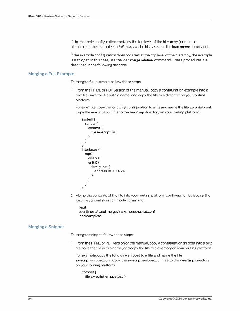
If the example configuration contains the top level of the hierarchy (or multiple
hierarchies), the example is a full example. In this case, use the loadmerge command.
If the example configuration does not start at the top level of the hierarchy, the example
is a snippet. In this case, use the loadmerge relative command. These procedures are
described in the following sections.
Merging a Full Example
To merge a full example, follow these steps:
1. From the HTML or PDF version of the manual, copy a configuration example into a
text file, save the file with a name, and copy the file to a directory on your routing
platform.
For example, copy the following configuration to a file and name the file ex-script.conf.
Copy the ex-script.conf file to the /var/tmp directory on your routing platform.
system {scripts {commit {file ex-script.xsl;
}}
}interfaces {fxp0 {disable;unit 0 {family inet {address 10.0.0.1/24;
}}
}}
2. Merge the contents of the file into your routing platform configuration by issuing the
loadmerge configuration mode command:
[edit]user@host# loadmerge /var/tmp/ex-script.confload complete
Merging a Snippet
To merge a snippet, follow these steps:
1. From the HTML or PDF version of the manual, copy a configuration snippet into a text
file, save the file with a name, and copy the file to a directory on your routing platform.
For example, copy the following snippet to a file and name the file
ex-script-snippet.conf. Copy the ex-script-snippet.conf file to the /var/tmp directory
on your routing platform.
commit {file ex-script-snippet.xsl; }
Copyright © 2014, Juniper Networks, Inc.xiv
IPsec VPNs Feature Guide for Security Devices

2. Move to the hierarchy level that is relevant for this snippet by issuing the following
configuration mode command:
[edit]user@host# edit system scripts[edit system scripts]
3. Merge the contents of the file into your routing platform configuration by issuing the
loadmerge relative configuration mode command:
[edit system scripts]user@host# loadmerge relative /var/tmp/ex-script-snippet.confload complete
For more information about the load command, see the CLI User Guide.
Documentation Conventions
Table 1 on page xv defines notice icons used in this guide.
Table 1: Notice Icons
DescriptionMeaningIcon
Indicates important features or instructions.Informational note
Indicates a situation that might result in loss of data or hardware damage.Caution
Alerts you to the risk of personal injury or death.Warning
Alerts you to the risk of personal injury from a laser.Laser warning
Indicates helpful information.Tip
Alerts you to a recommended use or implementation.Best practice
Table 2 on page xvi defines the text and syntax conventions used in this guide.
xvCopyright © 2014, Juniper Networks, Inc.
About the Documentation
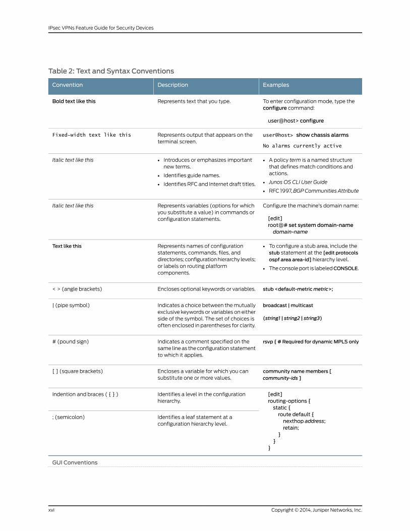
Table 2: Text and Syntax Conventions
ExamplesDescriptionConvention
To enter configuration mode, type theconfigure command:
user@host> configure
Represents text that you type.Bold text like this
user@host> show chassis alarms
No alarms currently active
Represents output that appears on theterminal screen.
Fixed-width text like this
• A policy term is a named structurethat defines match conditions andactions.
• Junos OS CLI User Guide
• RFC 1997,BGPCommunities Attribute
• Introduces or emphasizes importantnew terms.
• Identifies guide names.
• Identifies RFC and Internet draft titles.
Italic text like this
Configure the machine’s domain name:
[edit]root@# set system domain-namedomain-name
Represents variables (options for whichyou substitute a value) in commands orconfiguration statements.
Italic text like this
• To configure a stub area, include thestub statement at the [edit protocolsospf area area-id] hierarchy level.
• The console port is labeledCONSOLE.
Represents names of configurationstatements, commands, files, anddirectories; configuration hierarchy levels;or labels on routing platformcomponents.
Text like this
stub <default-metricmetric>;Encloses optional keywords or variables.< > (angle brackets)
broadcast | multicast
(string1 | string2 | string3)
Indicates a choice between the mutuallyexclusive keywords or variables on eitherside of the symbol. The set of choices isoften enclosed in parentheses for clarity.
| (pipe symbol)
rsvp { # Required for dynamicMPLS onlyIndicates a comment specified on thesame line as the configuration statementto which it applies.
# (pound sign)
community namemembers [community-ids ]
Encloses a variable for which you cansubstitute one or more values.
[ ] (square brackets)
[edit]routing-options {static {route default {nexthop address;retain;
}}
}
Identifies a level in the configurationhierarchy.
Indention and braces ( { } )
Identifies a leaf statement at aconfiguration hierarchy level.
; (semicolon)
GUI Conventions
Copyright © 2014, Juniper Networks, Inc.xvi
IPsec VPNs Feature Guide for Security Devices
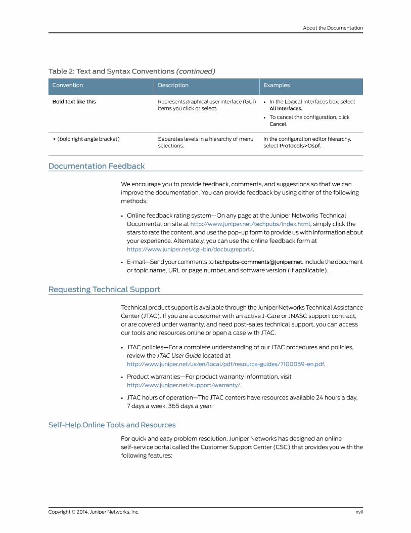
Table 2: Text and Syntax Conventions (continued)
ExamplesDescriptionConvention
• In the Logical Interfaces box, selectAll Interfaces.
• To cancel the configuration, clickCancel.
Represents graphical user interface (GUI)items you click or select.
Bold text like this
In the configuration editor hierarchy,select Protocols>Ospf.
Separates levels in a hierarchy of menuselections.
> (bold right angle bracket)
Documentation Feedback
We encourage you to provide feedback, comments, and suggestions so that we can
improve the documentation. You can provide feedback by using either of the following
methods:
• Online feedback rating system—On any page at the Juniper Networks Technical
Documentation site at http://www.juniper.net/techpubs/index.html, simply click the
stars to rate the content, and use the pop-up form to provide us with information about
your experience. Alternately, you can use the online feedback form at
https://www.juniper.net/cgi-bin/docbugreport/.
• E-mail—Send your comments to [email protected]. Include the document
or topic name, URL or page number, and software version (if applicable).
Requesting Technical Support
Technical product support is available through the Juniper Networks Technical Assistance
Center (JTAC). If you are a customer with an active J-Care or JNASC support contract,
or are covered under warranty, and need post-sales technical support, you can access
our tools and resources online or open a case with JTAC.
• JTAC policies—For a complete understanding of our JTAC procedures and policies,
review the JTAC User Guide located at
http://www.juniper.net/us/en/local/pdf/resource-guides/7100059-en.pdf.
• Product warranties—For product warranty information, visit
http://www.juniper.net/support/warranty/.
• JTAC hours of operation—The JTAC centers have resources available 24 hours a day,
7 days a week, 365 days a year.
Self-Help Online Tools and Resources
For quick and easy problem resolution, Juniper Networks has designed an online
self-service portal called the Customer Support Center (CSC) that provides you with the
following features:
xviiCopyright © 2014, Juniper Networks, Inc.
About the Documentation
• Find CSC offerings: http://www.juniper.net/customers/support/
• Search for known bugs: http://www2.juniper.net/kb/
• Find product documentation: http://www.juniper.net/techpubs/
• Find solutions and answer questions using our Knowledge Base: http://kb.juniper.net/
• Download the latest versions of software and review release notes:
http://www.juniper.net/customers/csc/software/
• Search technical bulletins for relevant hardware and software notifications:
http://kb.juniper.net/InfoCenter/
• Join and participate in the Juniper Networks Community Forum:
http://www.juniper.net/company/communities/
• Open a case online in the CSC Case Management tool: http://www.juniper.net/cm/
To verify service entitlement by product serial number, use our Serial Number Entitlement
(SNE) Tool: https://tools.juniper.net/SerialNumberEntitlementSearch/
Opening a Casewith JTAC
You can open a case with JTAC on the Web or by telephone.
• Use the Case Management tool in the CSC at http://www.juniper.net/cm/.
• Call 1-888-314-JTAC (1-888-314-5822 toll-free in the USA, Canada, and Mexico).
For international or direct-dial options in countries without toll-free numbers, see
http://www.juniper.net/support/requesting-support.html.
Copyright © 2014, Juniper Networks, Inc.xviii
IPsec VPNs Feature Guide for Security Devices

PART 1
Overview
• IP Security on page 3
• Route-Based VPN on page 25
• Policy-Based VPN on page 29
• Hub-and-Spoke VPN on page 31
• Loopback Interface for High Availability VPN on page 33
• VPN Support for Inserting Services Processing Cards on page 35
• IPv6 IPsec on page 37
• VPN Alarms on page 43
• Global SPI and VPN Monitoring on page 45
• VPN Session Affinity on page 47
• NAT Traversal on page 49
• Suite B Cryptographic Suites on page 51
1Copyright © 2014, Juniper Networks, Inc.

Copyright © 2014, Juniper Networks, Inc.2
IPsec VPNs Feature Guide for Security Devices

CHAPTER 1
IP Security
• VPN Overview on page 3
• Understanding IKE and IPsec Packet Processing on page 11
• Understanding Phase 1 of IKE Tunnel Negotiation on page 18
• Understanding Phase 2 of IKE Tunnel Negotiation on page 20
• Understanding Internet Key Exchange Version 2 on page 22
VPNOverview
Supported Platforms J Series, LN Series, SRX Series
A virtual private network (VPN) provides a means for securely communicating among
remote computers across a public WAN such as the Internet.
A VPN connection can link two LANs (site-to-site VPN) or a remote dial-up user and a
LAN. The traffic that flows between these two points passes through shared resources
such as routers, switches, and other network equipment that make up the public WAN.
To secure VPN communication while passing through the WAN, the two participants
create an IP Security (IPsec) tunnel.
NOTE: Theterm tunneldoesnotdenote tunnelmode(see“PacketProcessingin Tunnel Mode” on page 12). Instead, it refers to the IPsec connection.
IPsec is a suite of related protocols for cryptographically securing communications at
the IP Packet Layer. IPsec also provides methods for the manual and automatic
negotiation of security associations (SAs) and key distribution, all the attributes for which
are gathered in a domain of interpretation (DOI). The IPsec DOI is a document containing
definitions for all the security parameters required for the successful negotiation of a
VPN tunnel—essentially, all the attributes required for SA and IKE negotiations. See RFC
2407 and RFC 2408 for more information.
This topic includes the following sections:
• IPsec VPN Topologies on page 4
• Comparison of Policy-Based VPNs and Route-Based VPNs on page 4
• Security Associations on page 5
3Copyright © 2014, Juniper Networks, Inc.

• IPsec Key Management on page 6
• IPsec Security Protocols on page 8
• IPsec Tunnel Negotiation on page 9
• Distributed VPNs in SRX Series Services Gateways on page 10
• VPN Support for Inserting Services Processing Cards on page 10
IPsec VPN Topologies
The following are some of the IPsec VPN topologies that Junos operating system (OS)
supports:
• Site-to-site VPNs—Connects two sites in an organization together and allows secure
communications between the sites.
• Hub-and-spoke VPNs—Connects branch offices to the corporate office in an enterprise
network. You can also use this topology to connect spokes together by sending traffic
through the hub.
• Remote access VPNs—Allows users working at home or traveling to connect to the
corporate office and its resources. This topology is sometimes referred to as an
end-to-site tunnel.
Comparison of Policy-Based VPNs and Route-Based VPNs
Table 3 on page 4 summarizes the differences between policy-based VPNs and
route-based VPNs.
Table 3: Comparison Between Policy-Based VPNs and Route-Based VPNs
Route-Based VPNsPolicy-Based VPNs
In route-based VPNs, a policy does not specifically reference aVPN tunnel.
In policy-based VPNs, a tunnel is treated as an object that,together with source, destination, application, and action,constitutes a tunnel policy that permits VPN traffic.
A route determines which traffic is sent through the tunnel basedon a destination IP address.
A tunnel policy specifically references a VPN tunnel byname.
The number of route-based VPN tunnels that you create is limitedby the number of st0 interfaces (for point-to-point VPNs) or thenumber of tunnels that the device supports, whichever is lower.
The number of policy-based VPN tunnels that you cancreate is limited by the number of tunnels that the devicesupports.
Because the route, not the policy, determines which traffic goesthrough the tunnel, multiple policies can be supported with a singleSA or VPN.
With a policy-based VPN, although you can createnumerous tunnel policies referencing the same VPN tunnel,each tunnel policy pair creates an individual IPsec SA withthe remote peer. Each SA counts as an individual VPNtunnel.
In a route-based VPN, the regulation of traffic is not coupled to themeans of its delivery.
In a policy-based VPN, the action must be permit and mustinclude a tunnel.
Copyright © 2014, Juniper Networks, Inc.4
IPsec VPNs Feature Guide for Security Devices

Table 3: Comparison Between Policy-Based VPNs and Route-Based VPNs (continued)
Route-Based VPNsPolicy-Based VPNs
Route-based VPNs support the exchange of dynamic routinginformation through VPN tunnels. You can enable an instance ofa dynamic routing protocol, such as OSPF, on an st0 interface thatis bound to a VPN tunnel.
The exchange of dynamic routing information is notsupported in policy-based VPNs.
Route-based VPNs uses routes to specify the traffic sent to atunnel; a policy does not specifically reference a VPN tunnel.
If you need more granularity than a route can provide tospecify the traffic sent to a tunnel, using a policy-basedVPN with security policies is the best choice.
When the security device does a route lookup to find the interfacethrough which it must send traffic to reach an address, it finds aroute through a secure tunnel (st0) interface.
With a route-based VPN tunnel, you can consider a tunnel as ameans for delivering traffic, and can consider the policy as a methodfor either permitting or denying the delivery of that traffic.
With a policy-based VPN tunnel, you can consider a tunnelas an element in the construction of a policy.
Security Associations
A security association (SA) is a unidirectional agreement between the VPN participants
regarding the methods and parameters to use in securing a communication channel. Full
bidirectional communication requires at least two SAs, one for each direction. Through
the SA, an IPsec tunnel can provide the following security functions:
• Privacy (through encryption)
• Content integrity (through data authentication)
• Sender authentication and—if using certificates—nonrepudiation (through data origin
authentication)
The security functions you employ depend on your needs. If you need only to authenticate
the IP packet source and content integrity, you can authenticate the packet without
applying any encryption. On the other hand, if you are concerned only with preserving
privacy, you can encrypt the packet without applying any authentication mechanisms.
Optionally, you can both encrypt and authenticate the packet. Most network security
designers choose to encrypt, authenticate, and replay-protect their VPN traffic.
An IPsec tunnel consists of a pair of unidirectional SAs—one SA for each direction of the
tunnel—that specify the security parameter index (SPI), destination IP address, and
security protocol (Authentication Header [AH] or Encapsulating Security Payload [ESP]
employed. An SA groups together the following components for securing communications:
• Security algorithms and keys.
• Protocol mode, either transport or tunnel. Junos OS devices always use tunnel mode.
(See “Packet Processing in Tunnel Mode” on page 12.)
5Copyright © 2014, Juniper Networks, Inc.
Chapter 1: IP Security

• Key-management method, either manual key or AutoKey IKE. (See “IPsec Key
Management” on page 6.)
• SA lifetime.
For inbound traffic, Junos OS looks up the SA by using the following triplet:
• Destination IP address.
• Security protocol, either AH or ESP. (See “IPsec Security Protocols” on page 8.)
• Security parameter index (SPI) value.
For outbound VPN traffic, the policy invokes the SA associated with the VPN tunnel.
IPsec KeyManagement
The distribution and management of keys are critical to using VPNs successfully. Junos
OS supports IPsec technology for creating VPN tunnels with three kinds of key creation
mechanisms:
• Manual key
• AutoKey IKE with a preshared key or a certificate
You can choose your key creation mechanism—also called authentication method—during
Phase 1 and Phase 2 proposal configuration. See “IPsec Tunnel Negotiation” on page 9.
NOTE: Manual key creation and AutoKey IKE with certificates are notsupported with the dynamic VPN feature at this time.
This topic includes the following sections:
• Manual Key on page 6
• AutoKey IKE on page 7
• Diffie-Hellman Exchange on page 7
Manual Key
With manual keys, administrators at both ends of a tunnel configure all the security
parameters. This is a viable technique for small, static networks where the distribution,
maintenance, and tracking of keys are not difficult. However, safely distributing
manual-key configurations across great distances poses security issues. Aside from
passing the keys face-to-face, you cannot be completely sure that the keys have not
been compromised while in transit. Also, whenever you want to change the key, you are
faced with the same security issues as when you initially distributed it.
Copyright © 2014, Juniper Networks, Inc.6
IPsec VPNs Feature Guide for Security Devices

AutoKey IKE
When you need to create and manage numerous tunnels, you need a method that does
not require you to configure every element manually. IPsec supports the automated
generation and negotiation of keys and security associations using the Internet Key
Exchange (IKE) protocol. Junos OS refers to such automated tunnel negotiation as
AutoKey IKE and supports AutoKey IKE with preshared keys and AutoKey IKE with
certificates.
• AutoKey IKE with preshared keys—Using AutoKey IKE with preshared keys to
authenticate the participants in an IKE session, each side must configure and securely
exchange the preshared key in advance. In this regard, the issue of secure key distribution
is the same as that with manual keys. However, once distributed, an autokey, unlike a
manual key, can automatically change its keys at predetermined intervals using the
IKE protocol. Frequently changing keys greatly improves security, and automatically
doing so greatly reduces key-management responsibilities. However, changing keys
increases traffic overhead; therefore, changing keys too often can reduce data
transmission efficiency.
NOTE: A preshared key is a key for both encryption and decryption, whichboth participants must have before initiating communication.
• AutoKey IKE with certificates—When using certificates to authenticate the participants
during an AutoKey IKE negotiation, each side generates a public-private key pair and
acquires a certificate. As long as the issuing certificate authority (CA) is trusted by both
sides, the participants can retrieve the peer’s public key and verify the peer's signature.
There is no need to keep track of the keys and SAs; IKE does it automatically.
Diffie-Hellman Exchange
A Diffie-Hellman (DH) exchange allows participants to produce a shared secret value.
The strength of the technique is that it allows participants to create the secret value over
an unsecured medium without passing the secret value through the wire. There are five
DH groups; Junos OS supports groups 1, 2, 5, and 14. The size of the prime modulus used
in each group's calculation differs as follows:
• DH Group 1—768-bit modulus
• DH Group 2—1024-bit modulus
• DH Group 5—1536-bit modulus
• DH Group 14—2048-bit modulus
NOTE: The strength of DH Group 1 security has depreciated; therefore, wedo not recommend its use.
7Copyright © 2014, Juniper Networks, Inc.
Chapter 1: IP Security

The larger the modulus, the more secure the generated key is considered to be; however,
the larger the modulus, the longer the key-generation process takes. Because the modulus
for each DH group is a different size, the participants must agree to use the same group.
NOTE: If you configuremultiple (up to four) proposals for Phase 1negotiations, use the same DH group in all proposals. The same guidelineapplies tomultiple proposals for Phase 2 negotiations.
IPsec Security Protocols
IPsec uses two protocols to secure communications at the IP layer:
• Authentication Header (AH)—A security protocol for authenticating the source of an
IP packet and verifying the integrity of its content
• Encapsulating Security Payload (ESP)—A security protocol for encrypting the entire
IP packet (and authenticating its content)
You can choose your security protocols—also called authentication and encryption
algorithms—during Phase 2 proposal configuration. See “IPsec Tunnel Negotiation” on
page 9.
This topic includes the following sections:
• AH Protocol on page 8
• ESP Protocol on page 9
AHProtocol
The Authentication Header (AH) protocol provides a means to verify the authenticity
and integrity of the content and origin of a packet. You can authenticate the packet by
the checksum calculated through a Hash Message Authentication Code (HMAC) using
a secret key and either MD5 or SHA-1 hash functions.
• Message Digest 5 (MD5)—An algorithm that produces a 128-bit hash (also called a
digital signature or message digest) from a message of arbitrary length and a 16-byte
key. The resulting hash is used, like a fingerprint of the input, to verify content and
source authenticity and integrity.
• Secure Hash Algorithm (SHA-1)—An algorithm that produces a 160-bit hash from a
message of arbitrary length and a 20-byte key. It is generally regarded as more secure
than MD5 because of the larger hashes it produces. Because the computational
processing is done in the ASIC, the performance cost is negligible.
NOTE: For more information onMD5 hashing algorithms, see RFC 1321 andRFC 2403. For more information on SHA hashing algorithms, see RFC 2404.For more information on HMAC, see RFC 2104.
Copyright © 2014, Juniper Networks, Inc.8
IPsec VPNs Feature Guide for Security Devices
ESP Protocol
The Encapsulating Security Payload (ESP) protocol provides a means to ensure privacy
(encryption) and source authentication and content integrity (authentication). ESP in
tunnel mode encapsulates the entire IP packet (header and payload) and then appends
a new IP header to the now-encrypted packet. This new IP header contains the destination
address needed to route the protected data through the network. (See “Packet Processing
in Tunnel Mode” on page 12.)
With ESP, you can both encrypt and authenticate, encrypt only, or authenticate only. For
encryption, you can choose one of the following encryption algorithms:
• Data Encryption Standard (DES)—A cryptographic block algorithm with a 56-bit key.
• Triple DES (3DES)—A more powerful version of DES in which the original DES algorithm
is applied in three rounds, using a 168-bit key. DES provides significant performance
savings but is considered unacceptable for many classified or sensitive material
transfers.
• Advanced Encryption Standard (AES)—An emerging encryption standard which, when
adopted by Internet infrastructures worldwide, will offer greater interoperability with
other devices. Junos OS supports AES with 128-bit, 192-bit, and 256-bit keys.
For authentication, you can use either the MD5 or the SHA-1 algorithm.
NOTE: Even though it is possible to select NULL for encryption, it has been
demonstrated that IPsecmight be vulnerable to attack under suchcircumstances. Therefore, we suggest that you choose an encryptionalgorithm for maximum security.
IPsec Tunnel Negotiation
To establish an AutoKey IKE IPsec tunnel, two phases of negotiation are required:
• In Phase 1, the participants establish a secure channel in which to negotiate the IPsec
security associations (SAs).
• In Phase 2, the participants negotiate the IPsec SAs for encrypting and authenticating
the ensuing exchanges of user data.
For a manual key IPsec tunnel, because all the SA parameters have been previously
defined, there is no need to negotiate which SAs to use. In essence, the tunnel has already
been established. When traffic matches a policy using that manual key tunnel or when
a route involves the tunnel, the Juniper Networks device simply encrypts and authenticates
the data, as you determined, and forwards it to the destination gateway.
The remote IKE gateway address can be in any virtual routing (VR) instance. VR is
determined during IKE Phase 1 and Phase 2 negotiation. VR does not have to be configured
in the IKE proposals. If the IKE gateway interface is moved from one VR to another, the
9Copyright © 2014, Juniper Networks, Inc.
Chapter 1: IP Security

existing IKE Phase 1 and Phase 2 negotiations for the IKE gateway are cleared, and new
Phase 1 and Phase 2 negotiations are performed.
NOTE:
• OnSRXSeries devices,when you enable VPN, overlapping of IP addressesacross virtual routers is supported with the following limitations:
• An IKE external interface address cannot overlap with any other virtualrouter.
• An internal or trust interface address can overlap across virtual routers.
• An St0 interface address cannot overlap in route-based VPN in
point-to-multipoint tunnel such as NHTB.
• AnSt0 interfaceaddresscanoverlap in route-basedVPNinpoint-to-point
tunnel.
• The combinations of local IP addresses and remote gateway IP addressesof IP sec VPN tunnels configured across VRs have to be unique.
• When the loopback interface is used as the IKE gateway external interface,the physical interface for IKE negotiation should be in the same VR.
Distributed VPNs in SRX Series Services Gateways
In the SRX3000 and SRX5000 lines, the IKE provides tunnel management for IPsec and
authenticates end entities. The IKE performs a Diffie-Hellman (DH) key exchange to
generate an IPsec tunnel between network devices. The IPsec tunnels generated by IKE
are used to encrypt, decrypt, and authenticate user traffic between the network devices
at the IP layer.
The VPN is created by distributing the IKE and IPsec workload among the multiple Services
Processing Units (SPUs) of the platform. For site-to-site tunnels, least loaded SPC is
chosen as the anchor SPC. If multiple SPCs have the same smallest load, any of them
can be chosen as an anchor SPC. Here, load corresponds to the number of site-to-site
gateways or manual VPN tunnels anchored on an SPC. For dynamic tunnels, the newly
established dynamic tunnels will follow the round-robin algorithm.
In IPsec, the workload is distributed by the same algorithm that distributes the IKE. The
Phase 2 SA for a given VPN tunnel termination points pair is exclusively owned by a
particular SPU, and all IPsec packets belonging to this Phase 2 SA are forwarded to the
anchoring SPU of that SA for IPsec processing.
VPN Support for Inserting Services Processing Cards
The high-end SRX Series devices have a chassis-based distributed processor architecture.
The flow processing power is shared and is based on the number of Services Processing
Cards (SPCs). You can scale the processing power of the device by installing a new SPC.
Previously, whenever you installed a new SPC on a device either in standalone mode or
in chassis cluster mode, the distributed VPNs on the device were disrupted.
Copyright © 2014, Juniper Networks, Inc.10
IPsec VPNs Feature Guide for Security Devices

This feature enables you to insert an SPC on a device, in a chassis cluster, without
disrupting the traffic on the existing VPN tunnels created by the IKE and IPsec workload.
Now when you insert a new SPC in each chassis of the cluster, the existing tunnels are
not affected and traffic continues to flow over them without any disruption.
However, existing tunnels cannot use the processing power of the new SPC and
redistribute it to the new SPC. The newly inserted SPC can anchor the newly configured
site-to-site tunnels and dynamic tunnels. The newly configured tunnels are not guaranteed
to be anchored on the new SPC.
Site-to-site tunnels are anchored on different SPCs based on a load-balancing algorithm.
For site-to-site tunnels, the least loaded SPC is chosen as the anchor SPC. If multiple
SPCs have the same smallest load, then any of the SPCs can be chosen as the anchor
SPC. The newly configured site-to-site tunnels are guaranteed to be anchored on the
new SPC only if the load of the old SPCs are all greater than 0. The load corresponds to
the number of site-to-site gateways or manual VPN tunnels anchored on an SPC.
Dynamic tunnels are anchored on different SPCs based on a round-robin algorithm. The
newly configured dynamic tunnels are not guaranteed to be anchored on the new SPC.
RelatedDocumentation
IPsec VPNs Feature Guide for Security Devices•
• Example: Configuring a Policy-Based VPN on page 125
• Example: Configuring a Route-Based VPN on page 61
• Understanding IKE and IPsec Packet Processing on page 11
• Understanding Phase 1 of IKE Tunnel Negotiation on page 18
• Understanding Phase 2 of IKE Tunnel Negotiation on page 20
• Understanding Hub-and-Spoke VPNs on page 31
Understanding IKE and IPsec Packet Processing
Supported Platforms J Series, LN Series, SRX Series
An IPsec VPN tunnel consists of tunnel setup and applied security. During tunnel setup,
the peers establish security associations (SAs), which define the parameters for securing
traffic between themselves. (See “VPN Overview” on page 3.) After the tunnel is
established, IPsec protects the traffic sent between the two tunnel endpoints by applying
the security parameters defined by the SAs during tunnel setup. Within the Junos OS
implementation, IPsec is applied in tunnel mode, which supports the Encapsulating
Security Payload (ESP) and Authentication Header (AH) protocols.
This topic includes the following sections:
• Packet Processing in Tunnel Mode on page 12
• IKE Packet Processing on page 13
• IPsec Packet Processing on page 16
11Copyright © 2014, Juniper Networks, Inc.
Chapter 1: IP Security

Packet Processing in Tunnel Mode
IPsec operates in one of two modes—transport or tunnel. When both ends of the tunnel
are hosts, you can use either mode. When at least one of the endpoints of a tunnel is a
security gateway, such as a Junos OS router or firewall, you must use tunnel mode. Juniper
Networks devices always operate in tunnel mode for IPsec tunnels.
In tunnel mode, the entire original IP packet—payload and header—is encapsulated within
another IP payload, and a new header is appended to it, as shown in Figure 1 on page 12.
The entire original packet can be encrypted, authenticated, or both. With the
Authentication Header (AH) protocol, the AH and new headers are also authenticated.
With the Encapsulating Security Payload (ESP) protocol, the ESP header can also be
authenticated.
Figure 1: Tunnel Mode
In a site-to-site VPN, the source and destination addresses used in the new header are
the IP addresses of the outgoing interface. See Figure 2 on page 12.
Figure 2: Site-to-Site VPN in Tunnel Mode
Copyright © 2014, Juniper Networks, Inc.12
IPsec VPNs Feature Guide for Security Devices

In a dial-up VPN, there is no tunnel gateway on the VPN dial-up client end of the tunnel;
the tunnel extends directly to the client itself (see Figure 3 on page 13). In this case, on
packets sent from the dial-up client, both the new header and the encapsulated original
header have the same IP address: that of the client’s computer.
NOTE: Some VPN clients, such as the dynamic VPN client andNetscreen-Remote, use a virtual inner IP address (also called a “stickyaddress”). Netscreen-Remote enables you to define the virtual IP address.ThedynamicVPNclientuses thevirtual IPaddressassignedduring theXAuthconfiguration exchange. In such cases, the virtual inner IP address is thesource IP address in the original packet header of traffic originating from theclient, and the IP address that the ISP dynamically assigns the dial-up clientis the source IP address in the outer header.
Figure 3: Dial-Up VPN in Tunnel Mode
IKE Packet Processing
When a cleartext packet arrives on a Juniper Networks device that requires tunneling,
and no active Phase 2 SA exists for that tunnel, Junos OS begins IKE negotiations and
drops the packet. The source and destination addresses in the IP packet header are those
of the local and remote IKE gateways, respectively. In the IP packet payload, there is a
UDP segment encapsulating an ISAKMP (IKE) packet. The format for IKE packets is the
same for Phase 1 and Phase 2. See Figure 4 on page 14.
13Copyright © 2014, Juniper Networks, Inc.
Chapter 1: IP Security

Meanwhile, the source host has sent the dropped packet again. Typically, by the time
the second packet arrives, IKE negotiations are complete, and Junos OS protects the
packet and all subsequent packets in the session—with IPsec before forwarding it.
Figure 4: IKE Packet for Phases 1 and 2
The Next Payload field contains a number indicating one of the following payload types:
• 0002—SA Negotiation Payload contains a definition for a Phase 1 or Phase 2 SA.
• 0004—Proposal Payload can be a Phase 1 or Phase 2 proposal.
• 0008—Transform Payload gets encapsulated in a proposal payload that gets
encapsulated in an SA payload.
Copyright © 2014, Juniper Networks, Inc.14
IPsec VPNs Feature Guide for Security Devices

• 0010—Key Exchange (KE) Payload contains information necessary for performing a
key exchange, such as a DH public value.
• 0020—Identification (IDx) Payload.
• In Phase 1, IDii indicates the initiator ID, and IDir indicates the responder ID.
• In Phase 2, IDui indicates the user initiator, and IDur indicates the user responder.
The IDs are IKE ID types such as FQDN, U-FQDN, IP address, and ASN.1_DN.
• 0040—Certificate (CERT) Payload.
• 0080—Certificate Request (CERT_REQ) Payload.
• 0100—Hash (HASH) Payload contains the digest output of a particular hash function.
• 0200—Signature (SIG) Payload contains a digital signature.
• 0400—Nonce (Nx) Payload contains some pseudorandom information necessary for
the exchange).
• 0800—Notify Payload.
• 1000—ISAKMP Delete Payload.
• 2000—Vendor ID (VID) Payload can be included anywhere in Phase 1 negotiations.
Junos OS uses it to mark support for NAT-T.
Each ISAKMP payload begins with the same generic header, as shown in
Figure 5 on page 15.
Figure 5: Generic ISAKMPPayload Header
There can be multiple ISAKMP payloads chained together, with each subsequent payload
type indicated by the value in the Next Header field. A value of 0000 indicates the last
ISAKMP payload. See Figure 6 on page 16 for an example.
15Copyright © 2014, Juniper Networks, Inc.
Chapter 1: IP Security
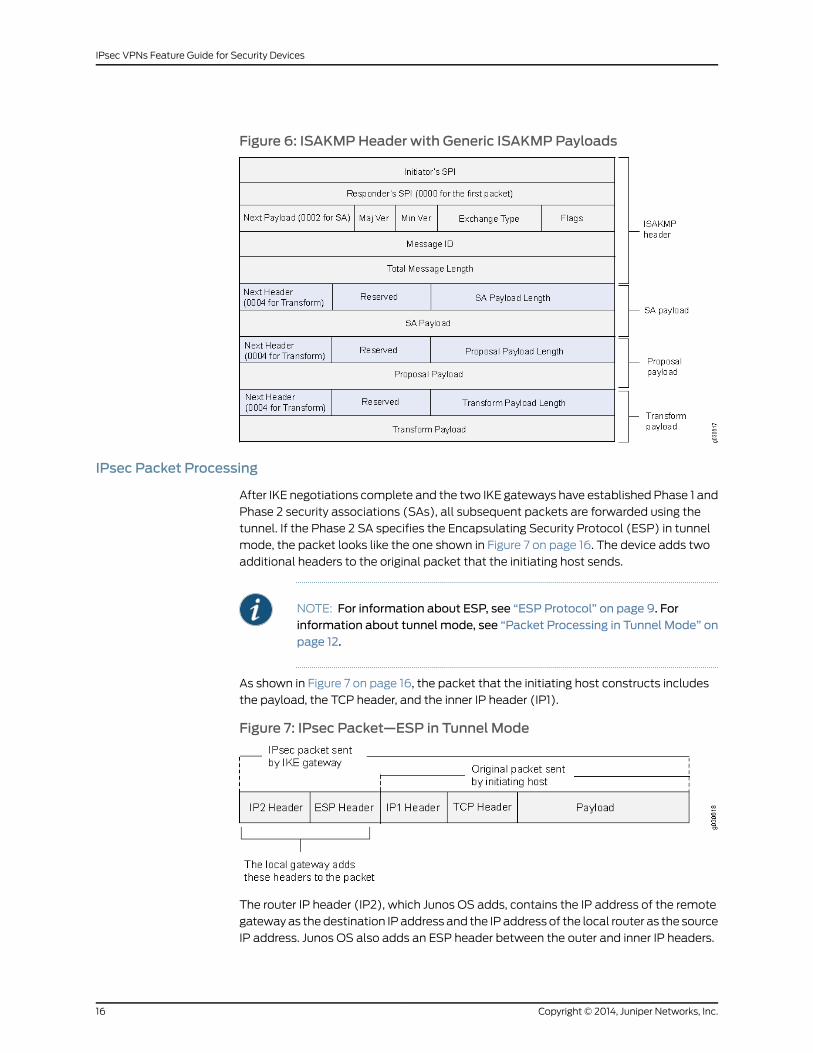
Figure 6: ISAKMPHeader with Generic ISAKMPPayloads
IPsec Packet Processing
After IKE negotiations complete and the two IKE gateways have established Phase 1 and
Phase 2 security associations (SAs), all subsequent packets are forwarded using the
tunnel. If the Phase 2 SA specifies the Encapsulating Security Protocol (ESP) in tunnel
mode, the packet looks like the one shown in Figure 7 on page 16. The device adds two
additional headers to the original packet that the initiating host sends.
NOTE: For information about ESP, see “ESP Protocol” on page 9. Forinformation about tunnel mode, see “Packet Processing in Tunnel Mode” onpage 12.
As shown in Figure 7 on page 16, the packet that the initiating host constructs includes
the payload, the TCP header, and the inner IP header (IP1).
Figure 7: IPsec Packet—ESP in Tunnel Mode
The router IP header (IP2), which Junos OS adds, contains the IP address of the remote
gateway as the destination IP address and the IP address of the local router as the source
IP address. Junos OS also adds an ESP header between the outer and inner IP headers.
Copyright © 2014, Juniper Networks, Inc.16
IPsec VPNs Feature Guide for Security Devices

The ESP header contains information that allows the remote peer to properly process
the packet when it receives it. This is shown in Figure 8 on page 17.
Figure 8: Outer IP Header (IP2) and ESPHeader
The Next Header field indicates the type of data in the payload field. In tunnel mode, this
value is 4, indicating an IP packet is contained within the payload. See Figure 9 on page 18.
17Copyright © 2014, Juniper Networks, Inc.
Chapter 1: IP Security
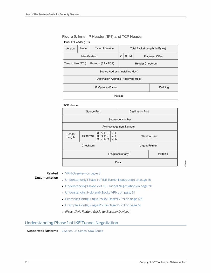
Figure 9: Inner IP Header (IP1) and TCPHeader
g030
688
Inner IP Header (IP1)
Version Header Type of Service
Identification O MD Fragment Offset
Header Checksum
Source Address (Installing Host)
Destination Address (Receiving Host)
IP Options (if any)
Payload
Padding
TCP Header
Time to Live (TTL) Protocol (6 for TCP)
Total Packet Length (in Bytes)
Source Port
Sequence Number
Acknowledgement Number
HeaderLength
Checksum
IP Options (if any)
Data
Padding
Destination Port
ReservedURG
ACK
RST
PSH
FIN
SYN
Window Size
Urgent Pointer
RelatedDocumentation
VPN Overview on page 3•
• Understanding Phase 1 of IKE Tunnel Negotiation on page 18
• Understanding Phase 2 of IKE Tunnel Negotiation on page 20
• Understanding Hub-and-Spoke VPNs on page 31
• Example: Configuring a Policy-Based VPN on page 125
• Example: Configuring a Route-Based VPN on page 61
• IPsec VPNs Feature Guide for Security Devices
Understanding Phase 1 of IKE Tunnel Negotiation
Supported Platforms J Series, LN Series, SRX Series
Copyright © 2014, Juniper Networks, Inc.18
IPsec VPNs Feature Guide for Security Devices

Phase 1 of an AutoKey Internet Key Exchange (IKE) tunnel negotiation consists of the
exchange of proposals for how to authenticate and secure the channel. The participants
exchange proposals for acceptable security services such as:
• Encryption algorithms—Data Encryption Standard (DES), triple Data Encryption
Standard (3DES), and Advanced Encryption Standard (AES). (See “IPsec Security
Protocols” on page 8.)
• Authentication algorithms—Message Digest 5 (MD5 ) and Secure Hash Algorithm
(SHA-1). (See “IPsec Security Protocols” on page 8.)
• Diffie-Hellman (DH) group. (See “Diffie-Hellman Exchange” on page 7.)
• Preshared key or RSA/DSA certificates. (See “IPsec Key Management” on page 6.)
A successful Phase 1 negotiation concludes when both ends of the tunnel agree to accept
at least one set of the Phase 1 security parameters proposed and then process them.
Juniper Networks devices support up to four proposals for Phase 1 negotiations, allowing
you to define how restrictive a range of security parameters for key negotiation you will
accept.
Junos OS provides the following predefined Phase 1 proposals:
• Standard—pre-g2-aes128-sha and pre-g2-3des-sha
• Compatible—pre-g2-3des-sha, pre-g2-3des-md5, pre-g2-des-sha, and pre-g2-des-md5
• Basic—pre-g1-des-sha and pre-g1-des-md5
You can also define custom Phase 1 proposals.
Phase 1 exchanges can take place in either main mode or aggressive mode. You can
choose your mode during IKE policy configuration.
This topic includes the following sections:
• Main Mode on page 19
• Aggressive Mode on page 20
MainMode
In main mode, the initiator and recipient send three two-way exchanges (six messages
total) to accomplish the following services:
• First exchange (messages 1 and 2)—Proposes and accepts the encryption and
authentication algorithms.
• Second exchange (messages 3 and 4)—Executes a DH exchange, and the initiator and
recipient each provide a pseudorandom number.
• Third exchange (messages 5 and 6)—Sends and verifies the identities of the initiator
and recipient.
19Copyright © 2014, Juniper Networks, Inc.
Chapter 1: IP Security
The information transmitted in the third exchange of messages is protected by the
encryption algorithm established in the first two exchanges. Thus, the participants’
identities are encrypted and therefore not transmitted “in the clear.”
Aggressive Mode
In aggressive mode, the initiator and recipient accomplish the same objectives as with
main mode, but in only two exchanges, with a total of three messages:
• First message—The initiator proposes the security association (SA), initiates a DH
exchange, and sends a pseudorandom number and its IKE identity.
• Second message—The recipient accepts the SA; authenticates the initiator; and sends
a pseudorandom number, its IKE identity, and, if using certificates, the recipient's
certificate.
• Third message—The initiator authenticates the recipient, confirms the exchange, and,
if using certificates, sends the initiator's certificate.
Because the participants’ identities are exchanged in the clear (in the first two messages),
aggressive mode does not provide identity protection.
NOTE: When a dial-up VPN user negotiates an AutoKey IKE tunnel with apreshared key, aggressivemodemust be used. Therefore, youmust alwaysuse aggressivemodewith the dynamic VPN feature. Note also that a dial-upVPN user can use an e-mail address, a fully qualified domain name (FQDN),or an IPaddressas its IKE ID.Adynamicpeer canuseeither ane-mail addressor an FQDN, but not an IP address.
RelatedDocumentation
VPN Overview on page 3•
• Understanding Phase 2 of IKE Tunnel Negotiation on page 20
• Example: Configuring a Policy-Based VPN on page 125
• Example: Configuring a Route-Based VPN on page 61
• IPsec VPNs Feature Guide for Security Devices
Understanding Phase 2 of IKE Tunnel Negotiation
Supported Platforms J Series, LN Series, SRX Series
After the participants have established a secure and authenticated channel, they proceed
through Phase 2, in which they negotiate security associations (SAs) to secure the data
to be transmitted through the IPsec tunnel.
Similar to the process for Phase 1, the participants exchange proposals to determine
which security parameters to employ in the SA. A Phase 2 proposal also includes a security
protocol—either Encapsulating Security Payload (ESP) or Authentication Header
Copyright © 2014, Juniper Networks, Inc.20
IPsec VPNs Feature Guide for Security Devices

(AH)—and selected encryption and authentication algorithms. The proposal can also
specify a Diffie-Hellman (DH) group, if Perfect Forward Secrecy (PFS) is desired.
Regardless of the mode used in Phase 1, Phase 2 always operates in quick mode and
involves the exchange of three messages.
Juniper Networks devices support up to four proposals for Phase 2 negotiations, allowing
you to define how restrictive a range of tunnel parameters you will accept. Junos OS
provides the following predefined Phase 2 proposals:
• Standard—g2-esp-3des-sha and g2-esp-aes128-sha
• Compatible—nopfs-esp-3des-sha, nopfs-esp-3des-md5, nopfs-esp-des-sha, and
nopfs-esp-des-md5
• Basic—nopfs-esp-des-sha and nopfs-esp-des-md5
You can also define custom Phase 2 proposals.
This topic includes the following sections:
• Proxy IDs on page 21
• Perfect Forward Secrecy on page 21
• Replay Protection on page 21
Proxy IDs
In Phase 2, the peers exchange proxy IDs. A proxy ID consists of a local and remote IP
address prefix. The proxy ID for both peers must match, which means that the local IP
address specified for one peer must be the same as the remote IP address specified for
the other peer.
Perfect Forward Secrecy
PFS is a method for deriving Phase 2 keys independent from and unrelated to the
preceding keys. Alternatively, the Phase 1 proposal creates the key (the SKEYID_d key)
from which all Phase 2 keys are derived. The SKEYID_d key can generate Phase 2 keys
with a minimum of CPU processing. Unfortunately, if an unauthorized party gains access
to the SKEYID_d key, all your encryption keys are compromised.
PFS addresses this security risk by forcing a new DH key exchange to occur for each
Phase 2 tunnel. Using PFS is thus more secure, although the rekeying procedure in Phase 2
might take slightly longer with PFS enabled.
Replay Protection
A replay attack occurs when an unauthorized person intercepts a series of packets and
uses them later either to flood the system, causing a denial of service (DoS), or to gain
entry to the trusted network. Junos OS provides a replay protection feature that enables
devices to check every IPsec packet to see if it has been received previously. If packets
arrive outside a specified sequence range, Junos OS rejects them. Use of this feature
does not require negotiation, because packets are always sent with sequence numbers.
You simply have the option of checking or not checking the sequence numbers.
21Copyright © 2014, Juniper Networks, Inc.
Chapter 1: IP Security

RelatedDocumentation
VPN Overview on page 3•
• Example: Configuring a Policy-Based VPN on page 125
• Example: Configuring a Route-Based VPN on page 61
• IPsec VPNs Feature Guide for Security Devices
Understanding Internet Key Exchange Version 2
Supported Platforms LN Series, SRX Series
Internet Key Exchange Version 2 (IKEv2) is the next generation standard for secure key
exchange between peer devices, defined in RFC 4306. IKEv2 is available in this release
for securing IPsec traffic.
The gateway configuration is used to distinguish between IKEv1 and IKEv2. A remote peer
is configured as either IKEv1 or IKEv2. When a peer is configured as IKEv2, it cannot fall
back to IKEv1 if the peer initiates IKEv1 negotiation. The default value for the version is
"v1-only". The version "v2-only" is supported from Junos OS Release 11.3 onward.
Use the version configuration statement at theeditsecurity ikegatewaygw-namehierarchy
level to configure IKEv2. To view the version information in the CLI, enter the following
commands:
• user@host>show security ike security-associations
• user@host>show security ipsec security-associations
The advantages of using version 2 over version 1 are as follows;
• Simplifies the existing IKEv1
• Single RFC, including NAT-T, EAP and remote address acquisition
• Replaces the 8 initial exchanges with a single 4 message exchange
• Reduces the latency for the IPSEC SA setup and increases connection establishment
speed.
• Increases robustness against DOS attack.
• Improves reliability through the use of sequence numbers, acknowledgements, and
error correction.
• Forward Compatibility
• Simple cryptographic mechanisms
• Traffic selector negotiation:
• IKEv1: Responder can just say yes/no
• IKEv2: Negotiation ability added
• Reliability
Copyright © 2014, Juniper Networks, Inc.22
IPsec VPNs Feature Guide for Security Devices

• All messages are request/response.
• Initiator is responsible for retransmission if it doesn’t receive a response.
IKEv2 includes support for:
• Route-based VPN
• Site-to-site VPN
• Dead peer detection (liveness check)
• Chassis cluster
• Certificate-based authentication
• Hardware offloading of the ModExp operations in a Diffie Hellman (DH) exchange
• Traffic selectors—An IKEv2 traffic selector is essentially the same as an IKEv1 Proxy-ID.
Traffic selectors and proxy-IDs are used the same way. IKEv2 specifies single traffic
selector in each direction.
• An IKEv2 child SA is known as a Phase 2 SA in IKEv1. The child SA differs in behavior
from the Phase 2 SA in the following ways:
• IKE and child SA rekeying—In IKEv2, a child security association (SA) cannot exist
without the underlying IKE SA. If a child SA is required, it will be rekeyed; however, if
the child SAs are currently active, the corresponding IKE SA will be rekeyed.
• Version 1 and version 2
RelatedDocumentation
• Example: Configuring a Route-Based VPN for IKEv2 on page 79
• IPsec VPNs Feature Guide for Security Devices
23Copyright © 2014, Juniper Networks, Inc.
Chapter 1: IP Security

Copyright © 2014, Juniper Networks, Inc.24
IPsec VPNs Feature Guide for Security Devices

CHAPTER 2
Route-Based VPN
• Understanding Route-Based IPsec VPNs on page 25
• Understanding Virtual Router Limitations on page 26
• Understanding Virtual Router Support for Route-Based VPNs on page 26
Understanding Route-Based IPsec VPNs
Supported Platforms J Series, LN Series, SRX Series
With route-based VPNs, you can configure dozens of security policies to regulate traffic
flowing through a single VPN tunnel between two sites, and there is just one set of IKE
and IPsec SAs at work. Unlike policy-based VPNs, for route-based VPNs, a policy refers
to a destination address, not a VPN tunnel. When Junos OS looks up a route to find the
interface to use to send traffic to the packet’s destination address, it finds a route through
a secure tunnel interface (st0.x). The tunnel interface is bound to a specific VPN tunnel,
and the traffic is routed to the tunnel if the policy action is permit.
Examples of where route-based VPNs can be used:
• There are overlapping subnets or IP addresses between the two LANs.
• A hub-and-spoke VPN topology is used in the network, and spoke-to-spoke traffic is
required.
• Primary and backup VPNs are required.
• A dynamic routing protocol (for example, OSPF, RIP, or BGP) is running across the
VPN.
NOTE: We recommend that you use route-based VPNwhen you want toconfigure VPN betweenmultiple remote sites. Route-based VPN allows forrouting between the spokes betweenmultiple remote sites; it is easier toconfigure, monitor, and troubleshoot.
Use policy-based VPNwhen your topology has a third-party device andrequires a separate SAs for each remote subnet.
25Copyright © 2014, Juniper Networks, Inc.
RelatedDocumentation
VPN Overview on page 3•
• Example: Configuring a Hub-and-Spoke VPN on page 171
• Example: Configuring a Policy-Based VPN on page 125
• IPsec VPNs Feature Guide for Security Devices
Understanding Virtual Router Limitations
Supported Platforms J Series, LN Series, SRX Series
The following features are not supported in this release for virtual router (VR):
• Dynamic endpoint VPN and remote access VPN inside VR
• Public key infrastructure (PKI) inside VR
• Chassis cluster active/active with VPN inside VR
RelatedDocumentation
Understanding Virtual Router Support for Route-Based VPNs on page 26•
• IPsec VPNs Feature Guide for Security Devices
Understanding Virtual Router Support for Route-Based VPNs
Supported Platforms J Series, LN Series, SRX Series
For route-based VPNs, you configure a unit of the secure tunnel (st0) interface and bind
it to the IPsec VPN tunnel. You can configure a unit of the st0 interface in different virtual
router instances. The following functions are supported for nondefault virtual router
instances:
• Manual key management
• Transit traffic
• Self-traffic
• VPN monitoring
• Hub-and-spoke VPNs
• Encapsulating Security Payload (ESP) protocol
• Authentication Header (AH) protocol
• Aggressive mode or main mode
• st0 anchored on the loopback (lo0) interface
• Maximum number of virtual routers (VRs) supported on an SRX Series device
• Applications such as Application Layer Gateway (ALG), Intrusion Detection and
Prevention (IDP), and Unified Threat Management (UTM)
• Dead peer detection (DPD)
Copyright © 2014, Juniper Networks, Inc.26
IPsec VPNs Feature Guide for Security Devices

• Chassis cluster active/backup
• Open Shortest Path First (OSPF) over st0
• Routing Information Protocol (RIP) over st0
• Policy-based VPN inside VR
RelatedDocumentation
• Understanding Virtual Router Limitations on page 26
• IPsec VPNs Feature Guide for Security Devices
27Copyright © 2014, Juniper Networks, Inc.
Chapter 2: Route-Based VPN

Copyright © 2014, Juniper Networks, Inc.28
IPsec VPNs Feature Guide for Security Devices

CHAPTER 3
Policy-Based VPN
• Understanding Policy-Based IPsec VPNs on page 29
Understanding Policy-Based IPsec VPNs
Supported Platforms J Series, LN Series, SRX Series
For policy-based IPsec VPNs, a security policy specifies as its action the VPN tunnel to
be used for transit traffic that meets the policy’s match criteria. A VPN is configured
independent of a policy statement. The policy statement refers to the VPN by name to
specify the traffic that is allowed access to the tunnel. For policy-based VPNs, each policy
creates an individual IPsec security association (SA) with the remote peer, each of which
counts as an individual VPN tunnel. For example, if a policy contains a group source
address and a group destination address, whenever one of the users belonging to the
address set attempts to communicate with any one of the hosts specified as the
destination address, a new tunnel is negotiated and established. Because each tunnel
requires its own negotiation process and separate pair of SAs, the use of policy-based
IPsec VPNs can be more resource-intensive than route-based VPNs.
Examples of where policy-based VPNs can be used:
• You are implementing a dial-up VPN.
• You require more granularity than a route can provide when determining which traffic
is sent to a tunnel (for example, you need to specify that traffic to a certain destination
goes through the tunnel only if the traffic originated from a particular source).
• The remote VPN device is a non-Juniper device that requires separate SAs for each
remote subnet.
NOTE: We recommend that you use route-based VPNwhen you want toconfigure VPN betweenmultiple remote sites. Route-based VPN allows forrouting between the spokes betweenmultiple remote sites; it is easier toconfigure, monitor, and troubleshoot.
Use policy-based VPNwhen your topology has a third-party device andrequires a separate SAs for each remote subnet.
29Copyright © 2014, Juniper Networks, Inc.
RelatedDocumentation
• VPN Overview on page 3
• Example: Configuring a Route-Based VPN on page 61
• Example: Configuring a Hub-and-Spoke VPN on page 171
• Example: Configuring a Policy-Based VPN on page 125
• IPsec VPNs Feature Guide for Security Devices
Copyright © 2014, Juniper Networks, Inc.30
IPsec VPNs Feature Guide for Security Devices

CHAPTER 4
Hub-and-Spoke VPN
• Understanding Hub-and-Spoke VPNs on page 31
Understanding Hub-and-Spoke VPNs
Supported Platforms J Series, LN Series, SRX Series
If you create two VPN tunnels that terminate at a device, you can set up a pair of routes
so that the device directs traffic exiting one tunnel to the other tunnel. You also need to
create a policy to permit the traffic to pass from one tunnel to the other. Such an
arrangement is known as hub-and-spoke VPN. (See Figure 10 on page 31.)
You can also configure multiple VPNs and route traffic between any two tunnels.
NOTE: SRX Series devices support only the route-based hub-and-spokefeature.
Figure 10: Multiple Tunnels in a Hub-and-Spoke VPN Configuration
RelatedDocumentation
• VPN Overview on page 3
• Example: Configuring a Hub-and-Spoke VPN on page 171
• IPsec VPNs Feature Guide for Security Devices
31Copyright © 2014, Juniper Networks, Inc.

Copyright © 2014, Juniper Networks, Inc.32
IPsec VPNs Feature Guide for Security Devices

CHAPTER 5
Loopback Interface for High AvailabilityVPN
• Understanding Loopback Interface for a High Availability VPN on page 33
Understanding Loopback Interface for a High Availability VPN
Supported Platforms LN Series, SRX Series
An Internet Key Exchange (IKE) gateway needs an external interface to communicate
with a peer device. In a high availability (HA) setup, the node on which the external
interface is active selects a Services Processing Unit (SPU) to support the VPN tunnel.
IKE and IPsec packets are processed on that SPU. Therefore, the active external interface
decides the anchor SPU.
In a HA setup, this external interface can be the reth interface or a standalone interface.
These interfaces can go down when the physical interfaces are down. Therefore, loopback
interfaces can be used to reach the peer gateway as they are alternate physical interfaces.
This feature allows the loopback interface to be configured for any redundancy group.
This redundancy group configuration is only checked for VPN packets, because only VPN
packets must find the anchor SPU through the active interface.
On branch SRX Series devices, the lo0 pseudointerface can be configured in any
redundancy group; for example, RG0, RG1, RG2, and so on. However, on high-end SRX
Series devices, the lo0 pseudointerface cannot be configured in RG0 when it is used as
an IKE gateway external interface. Because a VPN is only supported in an active-passive
HA environment on high-end SRX Series devices, the lo0 pseudointerface can be
configured in such a setup for RG1. In a HA setup, the node on which the external interface
is active selects an SPU to anchor the VPN tunnel. IKE and IPsec packets are processed
on that SPU. Thus an active external interface decides the anchor SPU.
RelatedDocumentation
• VPN Overview on page 3
33Copyright © 2014, Juniper Networks, Inc.

Copyright © 2014, Juniper Networks, Inc.34
IPsec VPNs Feature Guide for Security Devices
CHAPTER 6
VPN Support for Inserting ServicesProcessing Cards
• Understanding VPN Support for Inserting Services Processing Cards on page 35
Understanding VPN Support for Inserting Services Processing Cards
Supported Platforms LN Series, SRX3400, SRX3600, SRX5600, SRX5800
The high-end SRX Series devices have a chassis-based distributed processor architecture.
The flow processing power is shared and is based on the number of Services Processing
Cards (SPCs). You can scale the processing power of the device by installing a new SPC.
Previously, whenever you installed a new SPC on a device either in standalone mode or
in chassis cluster mode, the distributed VPNs on the device were disrupted.
This feature enables you to insert an SPC on a device, in a chassis cluster, without
disrupting the traffic on the existing VPN tunnels created by the IKE and IPsec workload.
Now when you insert a new SPC in each chassis of the cluster, the existing tunnels are
not affected and traffic continues to flow over them without any disruption.
However, existing tunnels cannot use the processing power of the new SPC and
redistribute it to the new SPC. The newly inserted SPC can anchor the newly configured
site-to-site tunnels and dynamic tunnels. The newly configured tunnels are not guaranteed
to be anchored on the new SPC.
Site-to-site tunnels are anchored on different SPCs based on a load-balancing algorithm.
For site-to-site tunnels, the least loaded SPC is chosen as the anchor SPC. If multiple
SPCs have the same smallest load, then any of the SPCs can be chosen as the anchor
SPC. The newly configured site-to-site tunnels are guaranteed to be anchored on the
new SPC only if the load of the old SPCs are all greater than 0. The load corresponds to
the number of site-to-site gateways or manual VPN tunnels anchored on an SPC.
Dynamic tunnels are anchored on different SPCs based on a round-robin algorithm. The
newly configured dynamic tunnels are not guaranteed to be anchored on the new SPC.
RelatedDocumentation
• VPN Overview on page 3
35Copyright © 2014, Juniper Networks, Inc.

Copyright © 2014, Juniper Networks, Inc.36
IPsec VPNs Feature Guide for Security Devices

CHAPTER 7
IPv6 IPsec
• Understanding IPv6 IKE and IPsec Packet Processing on page 37
Understanding IPv6 IKE and IPsec Packet Processing
Supported Platforms J Series, LN Series, SRX100, SRX210, SRX240, SRX650
An IPv6 IPsec VPN implementation involves the exchange of IPv6 packets within an IPv6
tunnel set up between two IPv6 tunnel endpoints. (See “VPN Overview” on page 3.)
This topic includes the following sections:
• Packet Processing in IPv6 6in6 Tunnel Mode on page 37
• IPv6 IKE Packet Processing on page 37
• IPv6 IPsec Packet Processing on page 39
Packet Processing in IPv6 6in6 Tunnel Mode
IPv6 VPN 6in6 tunneling is a technique for exchanging IPv6 packets within an IPv6 IPsec
tunnel between two site-to-site endpoints. In this mode, the original IPv6 packet is
encapsulated inside another IPv6 packet where both the outer and inner headers are
IPv6. The IPv6 addresses of the outer IPv6 header represent the tunnel endpoints, while
the IPv6 addresses of the inner IPv6 header represent the final source and destination
addresses. Unlike the transport mode, where the original IP header is retained, in the 6in6
tunneling mode, the entire original IPv6 packet (payload and header) is encapsulated
by appending a new outer IPv6 header, IPsec headers (AH or ESP), followed by the inner
IPv6 header, and the original IPv6 payload. The entire original IPv6 packet can be
encrypted, authenticated, or both. The Authentication Header (AH) protocol provides
authentication, while the Encapsulation Security Payload (ESP) protocol provides
encryption as well as authentication for the IPv6 packets.
IPv6 IKE Packet Processing
Internet Key Exchange (IKE) is part of the IPsec suite of protocols. It automatically enables
two tunnel endpoints to set up security associations (SAs) and negotiate secret keys
with each other. There is no need to manually configure the security parameters. IKE also
provides authentication for communicating peers.
IKE packet processing in IPv6 networks involves the following elements:
37Copyright © 2014, Juniper Networks, Inc.

• ISAKMP Identification Payload
Internet Security Association and Key Management Protocol (ISAKMP) identification
payload is used to identify and authenticate the communicating IPv6 peers. Two new
ID types—ID_IPV6_ADDR and ID_IPV6_ADDR_SUBNET—are enabled for IPv6. The ID
type indicates the type of identification to be used. The ID_IPV6_ADDR type specifies
a single 16-octet IPv6 address. This ID type represents an IPv6 address. The
ID_IPV6_ADDR_SUBNET type specifies a range of IPv6 addresses represented by two
16-octet values. This ID type represents an IPv6 network mask. Table 4 on page 38
lists the ID types and their assigned values in the identification payload.
Table 4: ISAKMP ID Types and Their Values
ValueID Type
0RESERVED
1ID_IPV4_ADDR
2ID_FQDN
3ID_USER_FQDN
4ID_IPV4_ADDR_SUBNET
5ID_IPV6_ADDR
6ID_IPV6_ADDR_SUBNET
7ID_IPV4_ADDR_RANGE
8ID_IPV6_ADDR_RANGE
9ID_DER_ASN1_DN
10ID_DER_ASN1_GN
11ID_KEY_ID
12ID_LIST
The ID_IPV6_ADDR_RANGE type specifies a range of IPv6 addresses represented by
two 16-octet values. The first octet value represents the starting IPv6 address and the
second octet value represents the ending IPv6 address in the range. All IPv6 addresses
falling between the first and last IPv6 addresses are considered to be part of the list.
NOTE: Two ID types in ISAKMP identificationpayload—ID_IPV6_ADDR_RANGE and ID_IPV4_ADDR_RANGE—are notsupported in this release.
Copyright © 2014, Juniper Networks, Inc.38
IPsec VPNs Feature Guide for Security Devices

• Proxy ID
A proxy ID is used during Phase 2 of IKE negotiation. It is generated before an IPsec
tunnel is established. A proxy ID identifies the SA to be used for the VPN. Two proxy
IDs are generated—local and remote. The local proxy ID refers to the local IPv6
address/network and subnet mask. The remote proxy ID refers to the remote IPv6
address/network and subnet mask.
• Security Association
An SA is an agreement between VPN participants to support secure communication.
SAs are differentiated based on three parameters—security parameter index (SPI),
destination IPv6 address, and security protocol (either AH or ESP). The SPI is a unique
value assigned to an SA to help identify an SA among multiple SAs. In an IPv6 packet,
the SA is identified from the destination address in the outer IPv6 header and the
security protocol is identified from either the AH or the ESP header.
IPv6 IPsec Packet Processing
After IKE negotiations are completed and the two IKE gateways have established Phase
1 and Phase 2 security associations (SAs), IPv6 IPsec employs authentication and
encryption technologies to secure the IPv6 packets.
This topic includes the following sections:
• AH Protocol in IPv6 on page 39
• ESP Protocol in IPv6 on page 40
• Integrity Check Value (ICV) Calculation in IPv6 on page 40
• Header Construction in IPv6 Tunnel Mode on page 40
AHProtocol in IPv6
The AH protocol provides data integrity and data authentication for IPv6 packets. IPv6
IPsec uses extension headers (for example, hop-by-hop and routing options) that must
be arranged in a particular way in the IPv6 datagram. In IPv6 AH tunnel mode, the AH
header immediately follows the new outer IPv6 header similar to that in IPv4 AH tunnel
mode. The extension headers are placed after the original inner IPv6 header. Therefore,
in IPv6 AH tunnel mode, the entire IPv6 packet is encapsulated by adding a new outer
IPv6 header, followed by an authentication header, an inner IPv6 header, extension
headers, and the rest of the original IPv6 datagram as shown in Figure 11 on page 39.
Figure 11: IPv6 AH Tunnel Mode
39Copyright © 2014, Juniper Networks, Inc.
Chapter 7: IPv6 IPsec

ESP Protocol in IPv6
ESP protocol provides both encryption and authentication for IPv6 packets. Because
IPv6 IPsec uses extension headers (for example, hop-by-hop and routing options) in the
IPv6 datagram, the most important difference between IPv6 ESP tunnel mode and IPv4
ESP tunnel mode is the placement of extension headers in the packet layout. In IPv6 ESP
tunnel mode, the ESP header immediately follows the new outer IPv6 header similar to
that in IPv4 ESP tunnel mode. Therefore, in IPv6 ESP tunnel mode, the entire IPv6 packet
is encapsulated by adding a new outer IPv6 header, followed by an ESP header, an inner
IPv6 header, extension headers, and the rest of the original IPv6 datagram as shown in
Figure 12 on page 40.
Figure 12: IPv6 ESP Tunnel Mode
Integrity Check Value (ICV) Calculation in IPv6
AH protocol verifies the integrity of the IPv6 packet by computing an Integrity Check
Value (ICV) on the packet contents. ICV is usually built over an authentication algorithm
such as MD5 or SHA-1. The IPv6 ICV calculations differ from that in IPv4 in terms of two
header fields—mutable header and optional extension header.
You can calculate the AH ICV over the IPv6 header fields that are either immutable in
transit or predictable in value upon arrival at the tunnel endpoints. You can also calculate
the AH ICV over the AH header and the upper level protocol data (considered to be
immutable in transit). You can calculate the ESP ICV over the entire IPv6 packet, excluding
the new outer IPv6 header and the optional extension headers.
NOTE: Unlike IPv4, IPv6 has amethod for tagging options asmutable intransit. IPv6 optional extension headers contain a flag that indicatesmutability. This flag determines the appropriate processing.
Header Construction in IPv6 Tunnel Mode
In IPv6 tunnel mode, the source and destination addresses of the outer IPv6 header
represent the tunnel endpoints, while the source and destination addresses of the inner
IPv6 header represent the final source and destination addresses. Table 5 on page 41
summarizes the differences between the outer IPv6 header and the inner IPv6 header.
Copyright © 2014, Juniper Networks, Inc.40
IPsec VPNs Feature Guide for Security Devices

Table 5: Comparison Between Outer Headers and Inner Headers
Inner HeaderOuter HeaderHeader Fields
No change.6version
No change.Copied from the inner header.DS field
Constructed.Copied from the inner header.ECN field
No change.Copied from the inner header.flow label
No change.Constructed.payload length
No change.AH, ESP, and routing header.next header
Decrement.64.hop limit
No change.Constructed.src address
No change.Constructed.dest address
No change.Never copied.extension headers
NOTE: This release supports IPv6 6in6 site-to-site VPN only. The IPv6 6in6site-to-site VPN uses IPv6 address as the IKE identity in this release.
RelatedDocumentation
• VPN Overview on page 3
• IPv6 IPsec Configuration Overview on page 213
• Example: Configuring an IPv6 IPsec Manual VPN on page 214
• Example: Configuring an IPv6 AutoKey IKE Policy-Based VPN on page 216
• IPsec VPNs Feature Guide for Security Devices
41Copyright © 2014, Juniper Networks, Inc.
Chapter 7: IPv6 IPsec

Copyright © 2014, Juniper Networks, Inc.42
IPsec VPNs Feature Guide for Security Devices
CHAPTER 8
VPN Alarms
• Understanding VPN Alarms and Auditing on page 43
Understanding VPNAlarms and Auditing
Supported Platforms LN Series, SRX100, SRX110, SRX210, SRX220, SRX240, SRX650
Configure the following command to enable security event logging during the initial set
up of the device.
set security log cache
The administrators (audit, cryptographic, IDS and security) cannot modify the security
event logging configuration if the above command is configured and each administrator
role is configured to have a distinct, unique set of privileges apart from all other
administrative roles.
Alarms are triggered by a VPN failure. A VPN alarm is generated when the system monitors
any of the following audited events:
• Authentication failures—You can configure the device to generate a system alarm when
the packet authentication failures reaches a specified number.
• Encryption and decryption failures—You can configure the device to generate a system
alarm when encryption or decryption failures exceed a specified number.
• IKE Phase 1 and IKEPhase 2 failures—Internet Key Exchange (IKE) Phase 1 negotiations
are used to establish IKE security associations (SAs). These SAs protect the IKE Phase
2 negotiations. You can configure the device to generate a system alarm when IKE
Phase 1 or IKE Phase 2 failures exceed a specified number.
• Self-test failures—Self tests are tests that a device runs upon power on or reboot to
verify whether security software is implemented correctly on your device.
Self-tests ensure the correctness of cryptographic algorithms. The JUNOS-FIPS image
performs self-tests automatically upon power-on, and continuously for key-pair
generation. In either domestic or FIPS images, self-tests may be configured to be
performed according to a defined schedule, upon demand or immediately after key
generation.
You can configure the device to generate a system alarm when a self-test failure occurs.
43Copyright © 2014, Juniper Networks, Inc.
• IDP flow policy attacks—An intrusion detection and prevention (IDP) policy allows you
to enforce various attack detection and prevention techniques on network traffic. You
can configure the device to generate a system alarm when IDP flow policy violations
occur.
• Replay attacks—A replay attack is a network attack in which a valid data transmission
is maliciously or fraudulently repeated or delayed. You can configure the device to
generate a system alarm when a replay attack occurs.
The syslog messages are included in the following cases:
• Failed symmetric key generation
• Failed asymmetric key generation
• Failed manual key distribution
• Failed automated key distribution
• Failed key destruction
• Failed key handling and storage
• Failed data encryption or decryption
• Failed signature
• Failed key agreement
• Failed cryptographic hashing
• IKE failure
• Failed authentication of the received packets
• Decryption error due to invalid padding content
• Mismatch in the length specified in the alternative subject field of the certificate received
from a remote VPN peer device.
Alarms are raised based on syslog messages. Every failure is logged, but an alarm is
generated only when a threshold is reached.
To view the alarm information, run the show security alarms command. The violation
count and the alarm do not persist across system reboots. After a reboot, the violation
count resets to zero, and the alarm is cleared from the alarm queue.
After appropriate actions have been taken, you can clear the alarm. The alarm remains
in the queue until you clear it (or until you reboot the device). To clear the alarm, run the
clear security alarms command.
RelatedDocumentation
• Example: Setting an Audible Alert as Notification of a Security Alarm on page 233
• Example: Generating Security Alarms in Response to Potential Violations on page 234
• IPsec VPNs Feature Guide for Security Devices
Copyright © 2014, Juniper Networks, Inc.44
IPsec VPNs Feature Guide for Security Devices
CHAPTER 9
Global SPI and VPNMonitoring
• Understanding Global SPI and VPN Monitoring Features on page 45
Understanding Global SPI and VPNMonitoring Features
Supported Platforms J Series, LN Series, SRX Series
You can monitor and maintain the efficient operation of your VPN using the following
global VPN features:
• SPI—Peers in a security association (SA) can become unsynchronized when one of
the peers fails. For example, if one of the peers reboots, it might send an incorrect
security parameter index (SPI). You can enable the device to detect such an event and
resynchronize the peers by configuring the bad SPI response feature.
• VPN monitoring—You can use the global VPN monitoring feature to periodically send
Internet Control Message Protocol (ICMP) requests to the peer to determine if the peer
is reachable.
RelatedDocumentation
• VPN Overview on page 3
• Example: Configuring Global SPI and VPN Monitoring Features on page 237
• IPsec VPNs Feature Guide for Security Devices
45Copyright © 2014, Juniper Networks, Inc.

Copyright © 2014, Juniper Networks, Inc.46
IPsec VPNs Feature Guide for Security Devices
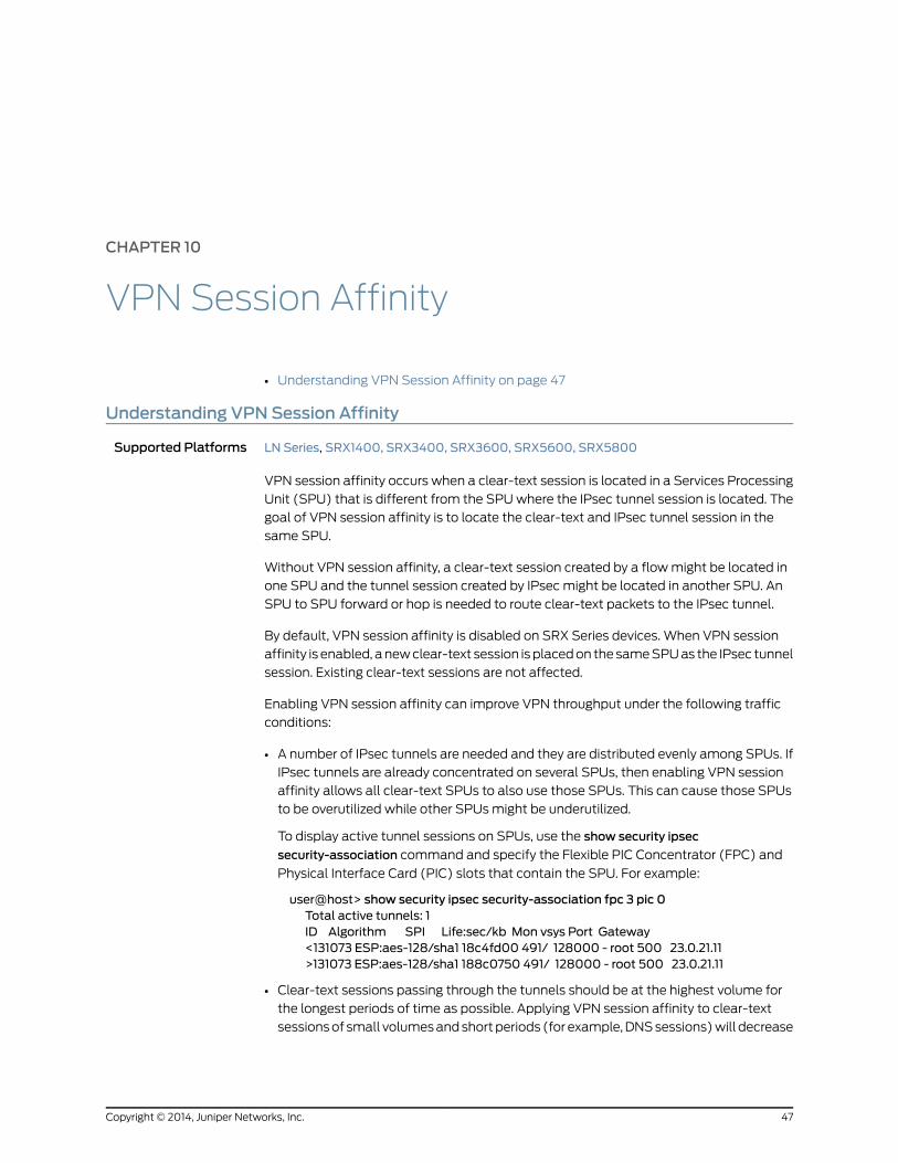
CHAPTER 10
VPN Session Affinity
• Understanding VPN Session Affinity on page 47
Understanding VPN Session Affinity
Supported Platforms LN Series, SRX1400, SRX3400, SRX3600, SRX5600, SRX5800
VPN session affinity occurs when a clear-text session is located in a Services Processing
Unit (SPU) that is different from the SPU where the IPsec tunnel session is located. The
goal of VPN session affinity is to locate the clear-text and IPsec tunnel session in the
same SPU.
Without VPN session affinity, a clear-text session created by a flow might be located in
one SPU and the tunnel session created by IPsec might be located in another SPU. An
SPU to SPU forward or hop is needed to route clear-text packets to the IPsec tunnel.
By default, VPN session affinity is disabled on SRX Series devices. When VPN session
affinity is enabled, a new clear-text session is placed on the same SPU as the IPsec tunnel
session. Existing clear-text sessions are not affected.
Enabling VPN session affinity can improve VPN throughput under the following traffic
conditions:
• A number of IPsec tunnels are needed and they are distributed evenly among SPUs. If
IPsec tunnels are already concentrated on several SPUs, then enabling VPN session
affinity allows all clear-text SPUs to also use those SPUs. This can cause those SPUs
to be overutilized while other SPUs might be underutilized.
To display active tunnel sessions on SPUs, use the show security ipsec
security-association command and specify the Flexible PIC Concentrator (FPC) and
Physical Interface Card (PIC) slots that contain the SPU. For example:
user@host> show security ipsec security-association fpc 3 pic 0Total active tunnels: 1ID Algorithm SPI Life:sec/kb Mon vsys Port Gateway<131073 ESP:aes-128/sha1 18c4fd00 491/ 128000 - root 500 23.0.21.11>131073 ESP:aes-128/sha1 188c0750 491/ 128000 - root 500 23.0.21.11
• Clear-text sessions passing through the tunnels should be at the highest volume for
the longest periods of time as possible. Applying VPN session affinity to clear-text
sessions of small volumes and short periods (for example, DNS sessions) will decrease
47Copyright © 2014, Juniper Networks, Inc.

the effect of session affinity and might even have a negative impact on VPN throughput
under certain conditions.
NOTE: You need to evaluate the tunnel distribution and traffic patterns inyour network to determine if VPN session affinity should be enabled.
The VPN session affinity limitations are as follows:
• Multicast traffic is not supported.
• Traffic across logical systems is not supported.
• If there is a route change, established clear-text sessions remain on an SPU and traffic
is rerouted if possible. Sessions created after the route change may be set up on a
different SPU.
• VPN session affinity only affects self traffic that terminates on the device (also known
as host-inbound traffic); self traffic that originates from the device (also known as
host-outbound traffic) is not affected.
• VPN session affinity can be enabled on an SRX1400 device; however, because the
device only has one SPU there is no affect on VPN throughput.
RelatedDocumentation
• Enabling VPN Session Affinity on page 239
• SRX1400, SRX3400, and SRX3600 Services Gateways Processing Overview
• SRX5600 and SRX5800 Services Gateways Processing Overview
• IPsec VPNs Feature Guide for Security Devices
Copyright © 2014, Juniper Networks, Inc.48
IPsec VPNs Feature Guide for Security Devices

CHAPTER 11
NAT Traversal
• Understanding NAT-T on page 49
Understanding NAT-T
Supported Platforms J Series, LN Series, SRX Series
Network Address Translation-Traversal (NAT-T) is a method for getting around IP address
translation issues encountered when data protected by IPsec passes through a NAT
device for address translation. Any changes to the IP addressing, which is the function
of NAT, causes IKE to discard packets. After detecting one or more NAT devices along
the data path during Phase 1 exchanges, NAT-T adds a layer of User Datagram Protocol
(UDP) encapsulation to IPsec packets so they are not discarded after address translation.
Junos OS implements NAT-T one-to-one IP addressing (static NAT) when a NAT device
is located along a VPN data path, such as in route-based, policy-based, and
hub-and-spoke topologies. The location of a NAT device can be such that:
• Only the initiator is behind a NAT device.
• Initiators connect through multiple NAT devices to the responder.
• Initiators are behind separate NAT devices.
• Only the responder is behind a NAT device.
• Both the initiator and the responder are behind a NAT device.
Configuration examples for NAT-T are provided for the topology in which only the
responder is behind a NAT device and the topology in which both the initiator and
responder are behind a NAT device. Site-to-site IKE gateway configuration for NAT-T is
supported on both the initiator and responder. A remote IKE ID is used to validate a peer’s
local IKE ID during Phase 1 of IKE tunnel negotiation. Both the initiator and responder
require a local-identity and a remote-identity setting.
All the VPN topologies use the following hardware:
• SRX Series Services Gateways
• J Series Services Routers
49Copyright © 2014, Juniper Networks, Inc.
NOTE: If SRX Series hardware is used as a responder, when you upgradeto the current JunosOS release, youmust upgrade the responder first, thenconfigure local-identity before upgrading the initiator. This approach is
required in caseof aDynamicEndPoint (DEP) scenario, inwhichan ID typeis used instead of an IP address. If the responder is not upgraded first, andaNATdevice is added in front of anSRXSeries responder, then the initiatorhardwaremust be configured such that remote-identity is the responder’s
private IP address.
RelatedDocumentation
• VPN Overview on page 3
• Example: Configuring a Route-Based VPN with Only the Responder Behind a NAT
Device on page 95
• Example: Configuring a Policy-Based VPN with Both an Initiator and a Responder
Behind a NAT Device on page 142
• IPsec VPNs Feature Guide for Security Devices
Copyright © 2014, Juniper Networks, Inc.50
IPsec VPNs Feature Guide for Security Devices

CHAPTER 12
Suite B Cryptographic Suites
• Understanding Suite B Cryptographic Suites on page 51
Understanding Suite B Cryptographic Suites
Supported Platforms LN Series, SRX110, SRX210, SRX220, SRX550, SRX5600, SRX5800, SRX650
Suite B is a set of cryptographic algorithms designated by the U.S. National Security
Agency to allow commercial products to protect traffic that is classified at secret or top
secret levels. Suite B protocols are defined in RFC 6379, Suite B Cryptographic Suites for
IPsec. The Suite B cryptographic suites provide Encapsulating Security Payload (ESP)
integrity and confidentiality and should be used when ESP integrity protection and
encryption are both required.
The following Suite B cryptographic suites are supported:
• Suite-B-GCM-128
• ESP: Advanced Encryption Standard (AES) encryption with 128-bit keys and 16-octet
integrity check value (ICV) in Galois Counter Mode (GCM).
• IKE: AES encryption with 128-bit keys in cipher block chaining (CBC) mode, integrity
using SHA-256 authentication, and key establishment using Diffie-Hellman (DH)
group 19 and authentication using Elliptic Curve Digital Signature Algorithm (ECDSA)
256-bit elliptic curve signatures.
• Suite-B-GCM-256
• ESP: AES encryption with 256-bit keys and 16-octet ICV in GCM for ESP.
• IKE: AES encryption with 256-bit keys in CBC mode, integrity using SHA-384
authentication, and key establishment using DH group 20 and authentication using
ECDSA 384-bit elliptic curve signatures.
IKEv1 and IKEv2 configuration is supported.
51Copyright © 2014, Juniper Networks, Inc.
NOTE: Suite B is not fully supported on SRX1400, SRX3400, and SRX3600devices,andonSRX5600andSRX5800devicesthatdonothavetheNG-SPCinstalled. You can configure IKE with Suite B options on these devices, butAES-GCMoptionsarenotsupported. If youconfigure IKEwithSuiteBoptionson these devices, VPN establishment is slower because the devices do nothave the hardware processors that can accelerate Suite B algorithmprocessing.
NOTE: Suite B is not supported with the group VPN feature.
CLI options support Suite B compliance in IKE and IPsec proposal configuration:
• For IKE proposals configured at the [edit security ikeproposalproposal-name] hierarchy
level:
• authentication-algorithm options include sha-256 and sha-384.
• authentication-method options include ecdsa-signatures-256 and
ecdsa-signatures-384.
• dh-group options include group19 and group20.
• For IPsec proposals configured at the [edit security ipsec proposal proposal-name]
hierarchy level, encryption-algorithm options include aes-128-gcm, aes-192-gcm, and
aes-256-gcm.
• For IPsec policies configured at the [edit security ipsec policy policy-name] hierarchy
level, the perfect-forward-secrecy keys options include group19 and group20.
• For convenience, predefined proposals that provide Suite B compliance—suiteb-gcm-128
and suiteb-gcm-256—are available at the [edit security ike policy policy-name] and
[edit security ipsec policy policy-name] hierarchy levels.
RelatedDocumentation
• VPN Overview on page 3
• [edit security ike] Hierarchy Level on page 244
• [edit security ipsec] Hierarchy Level on page 288
Copyright © 2014, Juniper Networks, Inc.52
IPsec VPNs Feature Guide for Security Devices
PART 2
Configuration
• IP Security on page 55
• Route-Based VPN on page 61
• Policy-Based VPN on page 125
• Hub-and-Spoke VPN on page 171
• Loopback Interface for High Availability VPN on page 205
• IPv6 IPsec on page 213
• VPN Alarms on page 233
• Global SPI and VPN Monitoring on page 237
• VPN Session Affinity on page 239
• IKE Configuration Statements on page 243
• IPsec Configuration Statements on page 287
• VPN Alarms Configuration Statements on page 327
53Copyright © 2014, Juniper Networks, Inc.

Copyright © 2014, Juniper Networks, Inc.54
IPsec VPNs Feature Guide for Security Devices

CHAPTER 13
IP Security
• IPsec VPN with Autokey IKE Configuration Overview on page 55
• IPsec VPN with Manual Keys Configuration Overview on page 56
• Recommended Configuration Options for Site-to-Site VPN with Static IP
Addresses on page 57
• Recommended Configuration Options for Site-to-Site or Dialup VPNs with Dynamic
IP Addresses on page 58
• Configuring IPsec VPN Using the VPN Wizard on page 59
IPsec VPNwith Autokey IKE Configuration Overview
Supported Platforms J Series, LN Series, SRX Series
IPsec VPN negotiation occurs in two phases. In Phase 1, participants establish a secure
channel in which to negotiate the IPsec security association (SA). In Phase 2, participants
negotiate the IPsec SA for authenticating traffic that will flow through the tunnel.
This overview describes the basic steps to configure a route-based or policy-based IPsec
VPN using autokey IKE (preshared keys or certificates).
To configure a route-based or policy-based IPsec VPN using autokey IKE:
1. Configure interfaces, security zones, and address book information.
(For route-based VPNs) Configure a secure tunnel st0.x interface. Configure routing
on the device.
2. Configure Phase 1 of the IPsec VPN tunnel.
a. (Optional) Configure a custom IKE Phase 1 proposal. This step is optional, as you
can use a predefined IKE Phase 1 proposal set (Standard, Compatible, or Basic).
b. Configure an IKE policy that references either your custom IKE Phase 1 proposal or
a predefined IKE Phase 1 proposal set. Specify autokey IKE preshared key or
certificate information. Specify the mode (main or aggressive) for the Phase 1
exchanges.
55Copyright © 2014, Juniper Networks, Inc.

c. Configure an IKE gateway that references the IKE policy. Specify the IKE IDs for the
local and remote devices. If the IP address of the remote gateway is not known,
specify how the remote gateway is to be identified.
3. Configure Phase 2 of the IPsec VPN tunnel.
a. (Optional) Configure a custom IPsec Phase 2 proposal. This step is optional, as
you can use a predefined IPsec Phase 2 proposal set (Standard, Compatible, or
Basic).
b. Configure an IPsec policy that references either your custom IPsec Phase 2 proposal
or a predefined IPsec Phase 2 proposal set. Specify perfect forward secrecy (PFS)
keys.
c. Configure an IPsec VPN tunnel that references both the IKE gateway and the IPsec
policy. Specify the proxy IDs to be used in Phase 2 negotiations.
(For route-based VPNs) Bind the secure tunnel interface st0.x to the IPsec VPN
tunnel.
4. Configure a security policy to permit traffic from the source zone to the destination
zone.
(For policy-based VPNs) Specify the security policy action tunnel ipsec-vpn with the
name of the IPsec VPN tunnel that you configured.
5. Update your global VPN settings. See “Example: Configuring Global SPI and VPN
Monitoring Features” on page 237.
RelatedDocumentation
Understanding Route-Based IPsec VPNs on page 25•
• Understanding Policy-Based IPsec VPNs on page 29
• Configuring IPsec VPN Using the VPN Wizard on page 59
• IPsec VPNs Feature Guide for Security Devices
IPsec VPNwithManual Keys Configuration Overview
Supported Platforms J Series, LN Series, SRX Series
This overview describes the basic steps to configure a route-based or policy-based IPsec
VPN using manual keys.
To configure a route-based or policy-based IPsec VPN using manual keys:
1. Configure interfaces, security zones, and address book information.
(For route-based VPNs) Configure routing. Configure a secure tunnel st0.x interface.
2. Configure an IPsec VPN tunnel by specifying the following parameters:
• Authentication algorithm and key
• Encryption algorithm and key
Copyright © 2014, Juniper Networks, Inc.56
IPsec VPNs Feature Guide for Security Devices
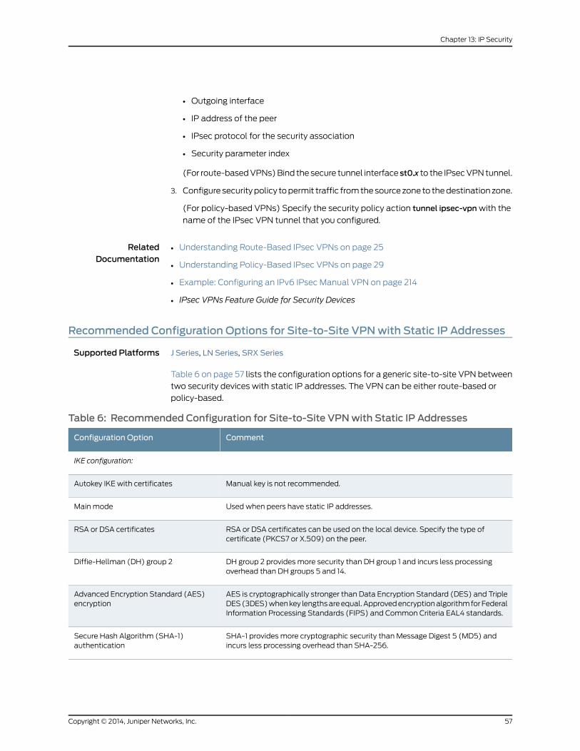
• Outgoing interface
• IP address of the peer
• IPsec protocol for the security association
• Security parameter index
(For route-based VPNs) Bind the secure tunnel interface st0.x to the IPsec VPN tunnel.
3. Configure security policy to permit traffic from the source zone to the destination zone.
(For policy-based VPNs) Specify the security policy action tunnel ipsec-vpn with the
name of the IPsec VPN tunnel that you configured.
RelatedDocumentation
Understanding Route-Based IPsec VPNs on page 25•
• Understanding Policy-Based IPsec VPNs on page 29
• Example: Configuring an IPv6 IPsec Manual VPN on page 214
• IPsec VPNs Feature Guide for Security Devices
Recommended Configuration Options for Site-to-Site VPNwith Static IP Addresses
Supported Platforms J Series, LN Series, SRX Series
Table 6 on page 57 lists the configuration options for a generic site-to-site VPN between
two security devices with static IP addresses. The VPN can be either route-based or
policy-based.
Table 6: Recommended Configuration for Site-to-Site VPNwith Static IP Addresses
CommentConfiguration Option
IKE configuration:
Manual key is not recommended.Autokey IKE with certificates
Used when peers have static IP addresses.Main mode
RSA or DSA certificates can be used on the local device. Specify the type ofcertificate (PKCS7 or X.509) on the peer.
RSA or DSA certificates
DH group 2 provides more security than DH group 1 and incurs less processingoverhead than DH groups 5 and 14.
Diffie-Hellman (DH) group 2
AES is cryptographically stronger than Data Encryption Standard (DES) and TripleDES (3DES) when key lengths are equal. Approved encryption algorithm for FederalInformation Processing Standards (FIPS) and Common Criteria EAL4 standards.
Advanced Encryption Standard (AES)encryption
SHA-1 provides more cryptographic security than Message Digest 5 (MD5) andincurs less processing overhead than SHA-256.
Secure Hash Algorithm (SHA-1)authentication
57Copyright © 2014, Juniper Networks, Inc.
Chapter 13: IP Security

Table6: RecommendedConfigurationforSite-to-SiteVPNwithStatic IPAddresses(continued)
CommentConfiguration Option
IP addresses are used by default if local and remote peers have static IP addresses.Specify the peer’s address. IP addresses can be used with a certificate if the IPaddress appears in the SubjectAltName field.
Local and remote IKE identifiers
IPsec configuration:
PFS DH group 2 provides increased security because the peers perform a secondDH exchange to produce the key used for IPsec encryption and decryption.
Perfect Forward Secrecy (PFS) DH group2
ESP provides both confidentiality through encryption and encapsulation of theoriginal IP packet and integrity through authentication.
Encapsulating Security Payload (ESP)protocol
AES is cryptographically stronger than DES and 3DES when key lengths are equal.Approved encryption algorithm for FIPS and Common Criteria EAL4 standards.
AES encryption
SHA-1 provides more cryptographic security than MD5.SHA-1 authentication
Enabled by default. Disabling this feature might resolve compatibility issues withthird-party peers.
Anti-replay protection
RelatedDocumentation
VPN Overview on page 3•
• IPsec VPNs Feature Guide for Security Devices
Recommended Configuration Options for Site-to-Site or Dialup VPNswith DynamicIP Addresses
Supported Platforms J Series, LN Series, SRX Series
Table 7 on page 58 lists the configuration options for a generic site-to-site or dialup VPN,
where the peer devices have dynamic IP addresses.
Table7:RecommendedConfigurationforSite-to-SiteorDialupVPNswithDynamic IPAddresses
CommentConfiguration Option
IKE configuration:
Manual key is not recommended.Autokey IKE with certificates
Required when the IP address of one or both of the IPsec peers is dynamicallyassigned.
Aggressive mode
RSA or DSA certificates can be used. Specify the certificate to be used on the localdevice. Specify the type of certificate (PKCS7 or X.509) on the peer.
1024-bit certificates
DH group 2 provides more security than DH group 1 and incurs less processingoverhead than DH groups 5 and 14.
Diffie-Hellman (DH) group 2
Copyright © 2014, Juniper Networks, Inc.58
IPsec VPNs Feature Guide for Security Devices
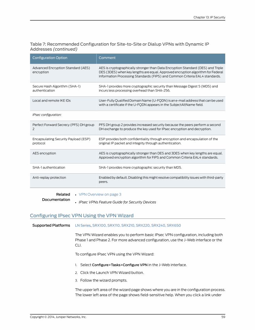
Table 7: Recommended Configuration for Site-to-Site or Dialup VPNswith Dynamic IPAddresses (continued)
CommentConfiguration Option
AES is cryptographically stronger than Data Encryption Standard (DES) and TripleDES (3DES) when key lengths are equal. Approved encryption algorithm for FederalInformation Processing Standards (FIPS) and Common Criteria EAL4 standards.
Advanced Encryption Standard (AES)encryption
SHA-1 provides more cryptographic security than Message Digest 5 (MD5) andincurs less processing overhead than SHA-256.
Secure Hash Algorithm (SHA-1)authentication
User-Fully Qualified Domain Name (U-FQDN) is an e-mail address that can be usedwith a certificate if the U-FQDN appears in the SubjectAltName field.
Local and remote IKE IDs
IPsec configuration:
PFS DH group 2 provides increased security because the peers perform a secondDH exchange to produce the key used for IPsec encryption and decryption.
Perfect Forward Secrecy (PFS) DH group2
ESP provides both confidentiality through encryption and encapsulation of theoriginal IP packet and integrity through authentication.
Encapsulating Security Payload (ESP)protocol
AES is cryptographically stronger than DES and 3DES when key lengths are equal.Approved encryption algorithm for FIPS and Common Criteria EAL4 standards.
AES encryption
SHA-1 provides more cryptographic security than MD5.SHA-1 authentication
Enabled by default. Disabling this might resolve compatibility issues with third-partypeers.
Anti-replay protection
RelatedDocumentation
VPN Overview on page 3•
• IPsec VPNs Feature Guide for Security Devices
Configuring IPsec VPNUsing the VPNWizard
Supported Platforms LN Series, SRX100, SRX110, SRX210, SRX220, SRX240, SRX650
The VPN Wizard enables you to perform basic IPsec VPN configuration, including both
Phase 1 and Phase 2. For more advanced configuration, use the J-Web interface or the
CLI.
To configure IPsec VPN using the VPN Wizard:
1. Select Configure>Tasks>Configure VPN in the J-Web interface.
2. Click the Launch VPN Wizard button.
3. Follow the wizard prompts.
The upper left area of the wizard page shows where you are in the configuration process.
The lower left area of the page shows field-sensitive help. When you click a link under
59Copyright © 2014, Juniper Networks, Inc.
Chapter 13: IP Security

the Resources heading, the document opens in your browser. If the document opens in
a new tab, be sure to close only the tab (not the browser window) when you close the
document.
RelatedDocumentation
• VPN Overview on page 3
• Understanding Phase 1 of IKE Tunnel Negotiation on page 18
• Understanding Phase 2 of IKE Tunnel Negotiation on page 20
Copyright © 2014, Juniper Networks, Inc.60
IPsec VPNs Feature Guide for Security Devices

CHAPTER 14
Route-Based VPN
• Example: Configuring a Route-Based VPN on page 61
• Example: Configuring a Route-Based VPN for IKEv2 on page 79
• Example: Configuring a Route-Based VPN with Only the Responder Behind a NAT
Device on page 95
• Example: Configuring an st0 Interface in a Virtual Router on page 120
Example: Configuring a Route-Based VPN
Supported Platforms J Series, LN Series, SRX Series
This example shows how to configure a route-based IPsec VPN to allow data to be
securely transferred between a branch office and the corporate office.
• Requirements on page 61
• Overview on page 61
• Configuration on page 65
• Verification on page 74
Requirements
This example uses the following hardware:
• SRX240 device
• SSG140 device
Before you begin, read “VPN Overview” on page 3.
Overview
In this example, you configure a route-based VPN for a branch office in Chicago, Illinois,
because you want to conserve tunnel resources but still get granular restrictions on VPN
traffic. Users in the Chicago office will use the VPN to connect to their corporate
headquarters in Sunnyvale, California.
Figure 13 on page 62 shows an example of a route-based VPN topology. In this topology,
the SRX Series device is located in Sunnyvale, and an SSG Series device (or a third-party
device) is located in Chicago.
61Copyright © 2014, Juniper Networks, Inc.

Figure 13: Route-Based VPN Topology
Trust zone
192.168.168.10/24
e0/02.2.2.2/30
e0/6192.168.168.1/24
Untrustzone
Internet
Trust zone
tunnel110.11.11.11/24VPN-chicago zone
SSG Series deviceChicago
ge-0/0/0.010.10.10.1/24
SRX Series device
Sunnyvale
10.10.10.10/24
st0.010.11.11.10/24VPN-chicago zone
ge-0/0/3.01.1.1.2/30
In this example, you configure interfaces, an IPv4 default route, security zones, and
address books. Then you configure IKE Phase 1, IPsec Phase 2, security policy, and
TCP-MSS parameters. See Table 8 on page 63 through Table 12 on page 64 for specific
configuration parameters used in this example.
Copyright © 2014, Juniper Networks, Inc.62
IPsec VPNs Feature Guide for Security Devices

Table 8: Interface, Static Route, Security Zone, and Address Book Information
Configuration ParametersNameFeature
10.10.10.1/24ge-0/0/0.0Interfaces
1.1.1.2/30ge-0/0/3.0
10.11.11.10/24st0.0 (tunnel interface)
The next hop is 1.1.1.1.0.0.0.0/0 (default route)Static routes
The next hop is st0.0.192.168.168.0/24
• All system services are allowed.
• The ge-0/0/0.0 interface is bound tothis zone.
trustSecurity zones
• IKE is the only allowed system service.
• The ge-0/0/3.0 interface is bound tothis zone.
untrust
The st0.0 interface is bound to this zone.vpn-chicago
• This address is an entry in the addressbookbook1, which is attached to a zonecalled trust.
• The address for this address book entryis 10.10.10.0/24.
sunnyvaleAddress book entries
• This address is an entry in the addressbookbook2, which is attached to a zonecalled vpn-chicago.
• The address for this address book entryis 192.168.168.0/24.
chicago
Table 9: IKE Phase 1 Configuration Parameters
Configuration ParametersNameFeature
• Authentication method: pre-shared-keys
• Diffie-Hellman group: group2
• Authentication algorithm: sha1
• Encryption algorithm: aes-128-cbc
ike-phase1-proposalProposal
• Mode: main
• Proposal reference: ike-phase1-proposal
• IKE Phase 1 policy authentication method: pre-shared-key ascii-text
ike-phase1-policyPolicy
• IKE policy reference: ike-phase1-policy
• External interface: ge-0/0/3.0
• Gateway address: 2.2.2.2
gw-chicagoGateway
63Copyright © 2014, Juniper Networks, Inc.
Chapter 14: Route-Based VPN

Table 10: IPsec Phase 2 Configuration Parameters
Configuration ParametersNameFeature
• Protocol: esp
• Authentication algorithm: hmac-sha1-96
• Encryption algorithm: aes-128-cbc
ipsec-phase2-proposalProposal
• Proposal reference: ipsec-phase2-proposal
• PFS: Diffie-Hellman group2
ipsec-phase2-policyPolicy
• IKE gateway reference: gw-chicago
• IPsec policy reference: ipsec-phase2-policy
• Bind to interface: st0.0
ike-vpn-chicagoVPN
Table 11: Security Policy Configuration Parameters
Configuration ParametersNamePurpose
• Match criteria:
• source-address sunnyvale
• destination-address chicago
• application any
• Action: permit
vpn-tr-chiThe security policy permits traffic from the trustzone to the vpn-chicago zone.
• Match criteria:
• source-address chicago
• destination-address sunnyvale
• application any
• Action: permit
vpn-chi-trThe security policy permits traffic from thevpn-chicago zone to the trust zone.
Table 12: TCP-MSS Configuration Parameters
Configuration ParametersPurpose
MSS value: 1350TCP-MSS is negotiated as part of the TCP three-way handshakeand limits the maximum size of a TCP segment to better fit theMTU limits on a network. For VPN traffic, the IPsec encapsulationoverhead, along with the IP and frame overhead, can cause theresulting ESP packet to exceed the MTU of the physical interface,which causes fragmentation. Fragmentation increases bandwidthand device resources.
NOTE: We recommend a value of 1350 as the starting point formost Ethernet-based networks with an MTU of 1500 or greater.You might need to experiment with different TCP-MSS values toobtain optimal performance. For example, you might need tochange the value if any device in the path has a lower MTU, or ifthere is any additional overhead such as PPP or Frame Relay.
Copyright © 2014, Juniper Networks, Inc.64
IPsec VPNs Feature Guide for Security Devices

Configuration
• Configuring Interface, Static Route, Security Zone, and Address Book
Information on page 65
• Configuring IKE on page 68
• Configuring IPsec on page 70
• Configuring Security Policies on page 71
• Configuring TCP-MSS on page 73
• Configuring the SSG Series Device on page 73
Configuring Interface,StaticRoute, SecurityZone, andAddressBook Information
CLI QuickConfiguration
To quickly configure this section of the example, copy the following commands, paste
them into a text file, remove any line breaks, change any details necessary to match your
network configuration, and then copy and paste the commands into the CLI at the [edit]
hierarchy level.
set interfaces ge-0/0/0 unit 0 family inet address 10.10.10.1/24set interfaces ge-0/0/3 unit 0 family inet address 1.1.1.2/30set interfaces st0 unit 0 family inet address 10.11.11.10/24set routing-options static route 0.0.0.0/0 next-hop 1.1.1.1set routing-options static route 192.168.168.0/24 next-hop st0.0set security zones security-zone untrust interfaces ge-0/0/3.0set security zones security-zone untrust host-inbound-traffic system-services ikeset security zones security-zone trust interfaces ge-0/0/0.0set security zones security-zone trust host-inbound-traffic system-services allset security zones security-zone vpn-chicago interfaces st0.0set security address-book book1 address sunnyvale 10.10.10.0/24set security address-book book1 attach zone trustset security address-book book2 address chicago 192.168.168.0/24set security address-book book2 attach zone vpn-chicago
Step-by-StepProcedure
The following example requires you to navigate various levels in the configuration
hierarchy. For instructions on how to do that, see Using the CLI Editor in Configuration
Mode.
To configure interface, static route, security zone, and address book information:
1. Configure Ethernet interface information.
[edit]user@host# set interfaces ge-0/0/0 unit 0 family inet address 10.10.10.1/24user@host# set interfaces ge-0/0/3 unit 0 family inet address 1.1.1.2/30user@host# set interfaces st0 unit 0 family inet address 10.11.11.10/24
2. Configure static route information.
[edit]user@host# set routing-options static route 0.0.0.0/0 next-hop 1.1.1.1user@host# set routing-options static route 192.168.168.0/24 next-hop st0.0
3. Configure the untrust security zone.
[edit ]
65Copyright © 2014, Juniper Networks, Inc.
Chapter 14: Route-Based VPN

user@host# edit security zones security-zone untrust
4. Assign an interface to the security zone.
[edit security zones security-zone untrust]user@host# set interfaces ge-0/0/3.0
5. Specify allowed system services for the security zone.
[edit security zones security-zone untrust]user@host# set host-inbound-traffic system-services ike
6. Configure the trust security zone.
[edit]user@host# edit security zones security-zone trust
7. Assign an interface to the trust security zone.
[edit security zones security-zone trust]user@host# set interfaces ge-0/0/0.0
8. Specify allowed system services for the trust security zone.
[edit security zones security-zone trust]user@host# set host-inbound-traffic system-services all
9. Configure an address book and attach a zone to it.
[edit security address-book book1]user@host# set address sunnyvale 10.10.10.0/24user@host# set attach zone trust
10. Configure the vpn-chicago security zone.
[edit]user@host# edit security zones security-zone vpn-chicago
11. Assign an interface to the security zone.
[edit security zones security-zone vpn-chicago]user@host# set interfaces st0.0
12. Configure another address book and attach a zone to it.
[edit security address-book book2]user@host# set address chicago 192.168.168.0/24user@host# set attach zone vpn-chicago
Results From configuration mode, confirm your configuration by entering the show interfaces,
show routing-options, show security zones, and show security address-book commands.
If the output does not display the intended configuration, repeat the configuration
instructions in this example to correct it.
[edit]user@host# show interfacesge-0/0/0 {unit 0 {family inet {address 10.10.10.1/24;
}}
Copyright © 2014, Juniper Networks, Inc.66
IPsec VPNs Feature Guide for Security Devices
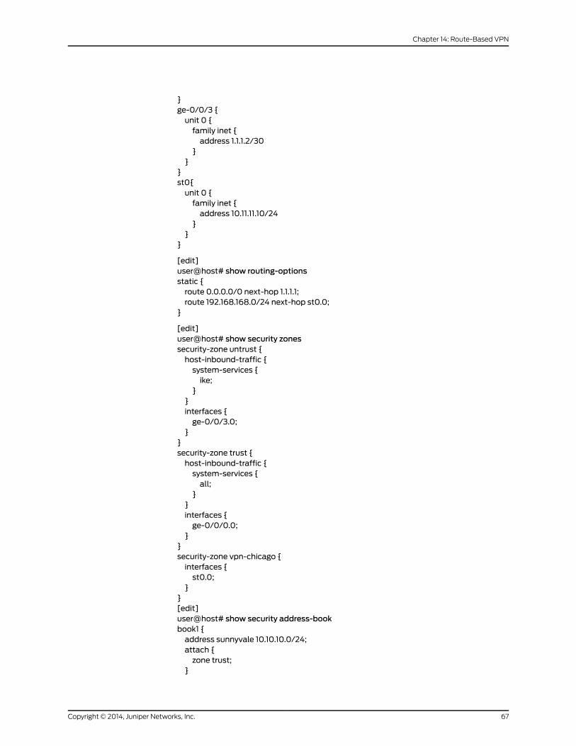
}ge-0/0/3 {unit 0 {family inet {address 1.1.1.2/30
}}
}st0{unit 0 {family inet {address 10.11.11.10/24
}}
}
[edit]user@host# show routing-optionsstatic {route 0.0.0.0/0 next-hop 1.1.1.1;route 192.168.168.0/24 next-hop st0.0;
}
[edit]user@host# show security zonessecurity-zone untrust {host-inbound-traffic {system-services {ike;
}}interfaces {ge-0/0/3.0;
}}security-zone trust {host-inbound-traffic {system-services {all;
}}interfaces {ge-0/0/0.0;
}}security-zone vpn-chicago {interfaces {st0.0;
}}[edit]user@host# show security address-bookbook1 {address sunnyvale 10.10.10.0/24;attach {zone trust;
}
67Copyright © 2014, Juniper Networks, Inc.
Chapter 14: Route-Based VPN

}book2 {address chicago 192.168.168.0/24;attach {zone vpn-chicago;
}}
If you are done configuring the device, enter commit from configuration mode.
Configuring IKE
CLI QuickConfiguration
To quickly configure this section of the example, copy the following commands, paste
them into a text file, remove any line breaks, change any details necessary to match your
network configuration, and then copy and paste the commands into the CLI at the [edit]
hierarchy level.
set security ike proposal ike-phase1-proposal authentication-method pre-shared-keysset security ike proposal ike-phase1-proposal dh-group group2set security ike proposal ike-phase1-proposal authentication-algorithm sha1set security ike proposal ike-phase1-proposal encryption-algorithm aes-128-cbcset security ike policy ike-phase1-policymodemainset security ike policy ike-phase1-policy proposals ike-phase1-proposalset security ike policy ike-phase1-policy pre-shared-key ascii-text 395psksecr3tset security ike gateway gw-chicago external-interface ge-0/0/3.0set security ike gateway gw-chicago ike-policy ike-phase1-policyset security ike gateway gw-chicago address 2.2.2.2
Step-by-StepProcedure
The following example requires you to navigate various levels in the configuration
hierarchy. For instructions on how to do that, see Using the CLI Editor in Configuration
Mode.
To configure IKE:
1. Create the IKE Phase 1 proposal.
[edit security ike]user@host# set proposal ike-phase1-proposal
2. Define the IKE proposal authentication method.
[edit security ike proposal ike-phase1-proposal]user@host# set authentication-method pre-shared-keys
3. Define the IKE proposal Diffie-Hellman group.
[edit security ike proposal ike-phase1-proposal]user@host# set dh-group group2
4. Define the IKE proposal authentication algorithm.
[edit security ike proposal ike-phase1-proposal]user@host# set authentication-algorithm sha1
5. Define the IKE proposal encryption algorithm.
[edit security ike proposal ike-phase1-proposal]user@host# set encryption-algorithm aes-128-cbc
Copyright © 2014, Juniper Networks, Inc.68
IPsec VPNs Feature Guide for Security Devices

6. Create an IKE Phase 1 policy.
[edit security ike]user@host# set policy ike-phase1-policy
7. Set the IKE Phase 1 policy mode.
[edit security ike policy ike-phase1-policy]user@host# setmodemain
8. Specify a reference to the IKE proposal.
[edit security ike policy ike-phase1-policy]user@host# set proposals ike-phase1-proposal
9. Define the IKE Phase 1 policy authentication method.
[edit security ike policy ike-phase1-policy]user@host# set pre-shared-key ascii-text 395psksecr3t
10. Create an IKE Phase 1 gateway and define its external interface.
[edit security ike]user@host# set gateway gw-chicago external-interface ge-0/0/3.0
11. Define the IKE Phase 1 policy reference.
[edit security ike gateway gw-chicago]user@host# set ike-policy ike-phase1-policy
12. Define the IKE Phase 1 gateway address.
[edit security ike gateway gw-chicago]user@host# set address 2.2.2.2
Results From configuration mode, confirm your configuration by entering the show security ike
command. If the output does not display the intended configuration, repeat the
configuration instructions in this example to correct it.
[edit]user@host# show security ikeproposal ike-phase1-proposal {authentication-method pre-shared-keys;dh-group group2;authentication-algorithm sha1;encryption-algorithm aes-128-cbc;
}policy ike-phase1-policy {modemain;proposals ike-phase1-proposal;pre-shared-key ascii-text "$9$9VMTp1RvWLdwYKMJDkmF3ylKM87Vb2oZjws5F"; ##SECRET-DATA
}gateway gw-chicago {ike-policy ike-phase1-policy;address 2.2.2.2;external-interface ge-0/0/3.0;
}
If you are done configuring the device, enter commit from configuration mode.
69Copyright © 2014, Juniper Networks, Inc.
Chapter 14: Route-Based VPN

Configuring IPsec
CLI QuickConfiguration
To quickly configure this section of the example, copy the following commands, paste
them into a text file, remove any line breaks, change any details necessary to match your
network configuration, and then copy and paste the commands into the CLI at the [edit]
hierarchy level.
set security ipsec proposal ipsec-phase2-proposal protocol espsetsecurity ipsecproposal ipsec-phase2-proposalauthentication-algorithmhmac-sha1-96set security ipsec proposal ipsec-phase2-proposal encryption-algorithm aes-128-cbcset security ipsec policy ipsec-phase2-policy proposals ipsec-phase2-proposalset security ipsec policy ipsec-phase2-policy perfect-forward-secrecy keys group2set security ipsec vpn ike-vpn-chicago ike gateway gw-chicagoset security ipsec vpn ike-vpn-chicago ike ipsec-policy ipsec-phase2-policyset security ipsec vpn ike-vpn-chicago bind-interface st0.0
Step-by-StepProcedure
The following example requires you to navigate various levels in the configuration
hierarchy. For instructions on how to do that, see Using the CLI Editor in Configuration
Mode.
To configure IPsec:
1. Create an IPsec Phase 2 proposal.
[edit]user@host# set security ipsec proposal ipsec-phase2-proposal
2. Specify the IPsec Phase 2 proposal protocol.
[edit security ipsec proposal ipsec-phase2-proposal]user@host# set protocol esp
3. Specify the IPsec Phase 2 proposal authentication algorithm.
[edit security ipsec proposal ipsec-phase2-proposal]user@host# set authentication-algorithm hmac-sha1-96
4. Specify the IPsec Phase 2 proposal encryption algorithm.
[edit security ipsec proposal ipsec-phase2-proposal]user@host# set encryption-algorithm aes-128-cbc
5. Create the IPsec Phase 2 policy.
[edit security ipsec]user@host# set policy ipsec-phase2-policy
6. Specify the IPsec Phase 2 proposal reference.
[edit security ipsec policy ipsec-phase2-policy]user@host# set proposals ipsec-phase2-proposal
7. Specify IPsec Phase 2 PFS to use Diffie-Hellman group 2.
[edit security ipsec policy ipsec-phase2-policy]user@host# set perfect-forward-secrecy keys group2
8. Specify the IKE gateway.
[edit security ipsec]
Copyright © 2014, Juniper Networks, Inc.70
IPsec VPNs Feature Guide for Security Devices

user@host# set vpn ike-vpn-chicago ike gateway gw-chicago
9. Specify the IPsec Phase 2 policy.
[edit security ipsec]user@host# set vpn ike-vpn-chicago ike ipsec-policy ipsec-phase2-policy
10. Specify the interface to bind.
[edit security ipsec]user@host# set vpn ike-vpn-chicago bind-interface st0.0
Results From configuration mode, confirm your configuration by entering the show security ipsec
command. If the output does not display the intended configuration, repeat the
configuration instructions in this example to correct it.
[edit]user@host# show security ipsecproposal ipsec-phase2-proposal {protocol esp;authentication-algorithm hmac-sha1-96;encryption-algorithm aes-128-cbc;
}policy ipsec-phase2-policy {perfect-forward-secrecy {keys group2;
}proposals ipsec-phase2-proposal;
}vpn ike-vpn-chicago {bind-interface st0.0;ike {gateway gw-chicago;ipsec-policy ipsec-phase2-policy;
}}
If you are done configuring the device, enter commit from configuration mode.
Configuring Security Policies
CLI QuickConfiguration
To quickly configure this section of the example, copy the following commands, paste
them into a text file, remove any line breaks, change any details necessary to match your
network configuration, and then copy and paste the commands into the CLI at the [edit]
hierarchy level.
set security policies from-zone trust to-zone vpn-chicago policy vpn-tr-chi matchsource-address sunnyvale
set security policies from-zone trust to-zone vpn-chicago policy vpn-tr-chi matchdestination-address chicago
set security policies from-zone trust to-zone vpn-chicago policy vpn-tr-chi matchapplication any
set security policies from-zone trust to-zone vpn-chicago policy vpn-tr-chi then permitset security policies from-zone vpn-chicago to-zone trust policy vpn-chi-tr matchsource-address chicago
71Copyright © 2014, Juniper Networks, Inc.
Chapter 14: Route-Based VPN

set security policies from-zone vpn-chicago to-zone trust policy vpn-chi-tr matchdestination-address sunnyvale
set security policies from-zone vpn-chicago to-zone trust policy vpn-chi-tr matchapplication any
set security policies from-zone vpn-chicago to-zone trust policy vpn-chi-tr then permit
Step-by-StepProcedure
The following example requires you to navigate various levels in the configuration
hierarchy. For instructions on how to do that, see Using the CLI Editor in Configuration
Mode.
To configure security policies:
1. Create the security policy to permit traffic from the trust zone to the vpn-chicago
zone.
[edit security policies from-zone trust to-zone vpn-chicago]user@host# set policy vpn-tr-chi match source-address sunnyvaleuser@host# set policy vpn-tr-chi match destination-address chicagouser@host# set policy vpn-tr-chi match application anyuser@host# set policy vpn-tr-chi then permit
2. Create the security policy to permit traffic from the vpn-chicago zone to the trust
zone.
[edit security policies from-zone vpn-chicago to-zone trust]user@host# set policy vpn-chi-tr match source-address sunnyvaleuser@host# set policy vpn-chi-tr match destination-address chicagouser@host# set policy vpn-chi-tr match application anyuser@host# set policy vpn-chi-tr then permit
Results From configuration mode, confirm your configuration by entering the showsecuritypolicies
command. If the output does not display the intended configuration, repeat the
configuration instructions in this example to correct it.
[edit]user@host# show security policiesfrom-zone trust to-zone vpn-chicago {policy vpn-tr-vpn {match {source-address sunnyvale;destination-address chicago;application any;
}then {permit;
}}
}from-zone vpn-chicago to-zone trust {policy vpn-tr-vpn {match {source-address chicago;destination-address sunnyvale;application any;
}
Copyright © 2014, Juniper Networks, Inc.72
IPsec VPNs Feature Guide for Security Devices

then {permit;
}}
}
If you are done configuring the device, enter commit from configuration mode.
Configuring TCP-MSS
CLI QuickConfiguration
To quickly configure this section of the example, copy the following command, paste it
into a text file, remove any line breaks, change any details necessary to match your
network configuration, and then copy and paste the command into the CLI at the [edit]
hierarchy level.
set security flow tcp-mss ipsec-vpnmss 1350
Step-by-StepProcedure
The following example requires you to navigate various levels in the configuration
hierarchy. For instructions on how to do that, see Using the CLI Editor in Configuration
Mode.
To configure TCP-MSS information:
1. Configure TCP-MSS information.
[edit]user@host# set security flow tcp-mss ipsec-vpnmss 1350
Results From configuration mode, confirm your configuration by entering the show security flow
command. If the output does not display the intended configuration, repeat the
configuration instructions in this example to correct it.
[edit]user@host# show security flowtcp-mss {ipsec-vpn {mss 1350;
}}
If you are done configuring the device, enter commit from configuration mode.
Configuring the SSG Series Device
CLI QuickConfiguration
For reference, the configuration for the SSG Series device is provided. For information
about configuring SSG Series devices, see theConceptsandExamplesScreenOSReference
Guide, which is located at http://www.juniper.net/techpubs .
To quickly configure this section of the example, copy the following commands, paste
them into a text file, remove any line breaks, change any details necessary to match your
network configuration, and then copy and paste the commands into the CLI.
set zone name vpn-chicagoset interface ethernet0/6 zone Trust
73Copyright © 2014, Juniper Networks, Inc.
Chapter 14: Route-Based VPN

set interface ethernet0/0 zone Untrustset interface tunnel.1 zone vpn-chicagoset interface ethernet0/6 ip 192.168.168.1/24set interface ethernet0/6 routeset interface ethernet0/0 ip 2.2.2.2/30set interface ethernet0/0 routeset interface tunnel.1 ip 10.11.11.11/24set flow tcp-mss 1350set address Trust “192.168.168-net” 192.168.168.0 255.255.255.0set address vpn-chicago "10.10.10-net" 10.10.10.0 255.255.255.0set ike gateway corp-ike address 1.1.1.2 Main outgoing-interface ethernet0/0 preshare395psksecr3t sec-level standard
set vpn corp-vpn gateway corp-ike replay tunnel idletime 0 sec-level standardset vpn corp-vpnmonitor optimized rekeyset vpn corp-vpn bind interface tunnel.1set policy from Trust to Untrust “ANY” “ANY” “ANY” nat src permitset policy from Trust to vpn-chicago “192.168.168-net” “10.10.10-net” “ANY” permitset policy from vpn-chicago to Trust “10.10.10-net” “192.168.168-net” “ANY” permitset route 10.10.10.0/24 interface tunnel.1set route 0.0.0.0/0 interface ethernet0/0 gateway 2.2.2.1
Verification
To confirm that the configuration is working properly, perform these tasks:
• Verifying the IKE Phase 1 Status on page 74
• Verifying the IPsec Phase 2 Status on page 76
• Reviewing Statistics and Errors for an IPsec Security Association on page 77
• Testing Traffic Flow Across the VPN on page 78
Verifying the IKE Phase 1 Status
Purpose Verify the IKE Phase 1 status.
Action NOTE: Before starting the verification process, you need to send traffic froma host in the 10.10.10/24 network to a host in the 192.168.168/24 network.For route-basedVPNs, trafficcanbe initiatedbytheSRXSeriesdevice throughthe tunnel. We recommend that when testing IPsec tunnels, test traffic besent from a separate device on one side of the VPN to a second device onthe other side of the VPN. For example, initiate a ping from 10.10.10.10 to192.168.168.10.
From operational mode, enter the showsecurity ikesecurity-associationscommand. After
obtaining an index number from the command, use the show security ike
security-associations index index_number detail command.
user@host> show security ike security-associationsIndex Remote Address State Initiator cookie Responder cookie Mode1 2.2.2.2 UP 744a594d957dd513 1e1307db82f58387 Main
Copyright © 2014, Juniper Networks, Inc.74
IPsec VPNs Feature Guide for Security Devices

user@host> show security ike security-associations index 1 detailIKE peer 2.2.2.2, Index 1, Role: Responder, State: UP Initiator cookie: 744a594d957dd513, Responder cookie: 1e1307db82f58387 Exchange type: Main, Authentication method: Pre-shared-keys Local: 1.1.1.2:500, Remote: 2.2.2.2:500 Lifetime: Expires in 28570 seconds Algorithms: Authentication : sha1 Encryption : aes-cbc (128 bits) Pseudo random function: hmac-sha1 Traffic statistics: Input bytes : 852 Output bytes : 940 Input packets : 5 Output packets : 5 Flags: Caller notification sent IPSec security associations: 1 created, 0 deleted Phase 2 negotiations in progress: 0
Meaning The show security ike security-associations command lists all active IKE Phase 1 SAs. If
no SAs are listed, there was a problem with Phase 1 establishment. Check the IKE policy
parameters and external interface settings in your configuration.
If SAs are listed, review the following information:
• Index—This value is unique for each IKE SA, which you can use in the show security ike
security-associations index detail command to get more information about the SA.
• Remote Address—Verify that the remote IP address is correct.
• State
• UP—The Phase 1 SA has been established.
• DOWN—There was a problem establishing the Phase 1 SA.
• Mode—Verify that the correct mode is being used.
Verify that the following are correct in your configuration:
• External interfaces (the interface must be the one that receives IKE packets)
• IKE policy parameters
• Preshared key information
• Phase 1 proposal parameters (must match on both peers)
The show security ike security-associations index 1 detail command lists additional
information about the security association with an index number of 1:
• Authentication and encryption algorithms used
• Phase 1 lifetime
• Traffic statistics (can be used to verify that traffic is flowing properly in both directions)
• Role information
75Copyright © 2014, Juniper Networks, Inc.
Chapter 14: Route-Based VPN

NOTE: Troubleshooting is best performedon the peer using the responderrole.
• Initiator and responder information
• Number of IPsec SAs created
• Number of Phase 2 negotiations in progress
Verifying the IPsec Phase 2 Status
Purpose Verify the IPsec Phase 2 status.
Action From operational mode, enter the show security ipsec security-associations command.
After obtaining an index number from the command, use the show security ipsec
security-associations index index_number detail command.
user@host> show security ipsec security-associations total configured sa: 2 ID Gateway Port Algorithm SPI Life:sec/kb Mon vsys
<16384 2.2.2.2 500 ESP:aes-128/sha1 76d64d1d 3363/ unlim - 0 >16384 2.2.2.2 500 ESP:aes-128/sha1 a1024ee2 3363/ unlim - 0
user@host> show security ipsec security-associations index 16384 detail Virtual-system: Root Local Gateway: 1.1.1.2, Remote Gateway: 2.2.2.2 Local Identity: ipv4_subnet(any:0,[0..7]=10.10.10.0/24) Remote Identity: ipv4_subnet(any:0,[0..7]=192.168.168.0/24) DF-bit: clear
Direction: inbound, SPI: 1993755933, AUX-SPI: 0 Hard lifetime: Expires in 3352 seconds Lifesize Remaining: Unlimited Soft lifetime: Expires in 2775 seconds Mode: tunnel, Type: dynamic, State: installed, VPN Monitoring: - Protocol: ESP, Authentication: hmac-sha1-96, Encryption: aes-cbc (128 bits)
Anti-replay service: enabled, Replay window size: 32
Direction: outbound, SPI: 2701283042, AUX-SPI: 0 Hard lifetime: Expires in 3352 seconds Lifesize Remaining: Unlimited Soft lifetime: Expires in 2775 seconds Mode: tunnel, Type: dynamic, State: installed, VPN Monitoring: - Protocol: ESP, Authentication: hmac-sha1-96, Encryption: aes-cbc (128 bits) Anti-replay service: enabled, Replay window size: 32
Meaning The output from the showsecurity ipsecsecurity-associationscommand lists the following
information:
Copyright © 2014, Juniper Networks, Inc.76
IPsec VPNs Feature Guide for Security Devices

• The ID number is 16384. Use this value with the showsecurity ipsecsecurity-associations
index command to get more information about this particular SA.
• There is one IPsec SA pair using port 500, which indicates that no NAT-traversal is
implemented. (NAT-traversal uses port 4500 or another random high-number port.)
• The SPIs, lifetime (in seconds), and usage limits (or lifesize in KB) are shown for both
directions. The 3363/ unlim value indicates that the Phase 2 lifetime expires in 3363
seconds, and that no lifesize has been specified, which indicates that it is unlimited.
Phase 2 lifetime can differ from Phase 1 lifetime, as Phase 2 is not dependent on Phase
1 after the VPN is up.
• VPN monitoring is not enabled for this SA, as indicated by a hyphen in the Mon column.
If VPN monitoring is enabled, U indicates that monitoring is up, and D indicates that
monitoring is down.
• The virtual system (vsys) is the root system, and it always lists 0.
The output from the showsecurity ipsecsecurity-associations index16384detailcommand
lists the following information:
• The local identity and remote identity make up the proxy ID for the SA.
A proxy ID mismatch is one of the most common causes for a Phase 2 failure. If no
IPsec SA is listed, confirm that Phase 2 proposals, including the proxy ID settings, are
correct for both peers. For route-based VPNs, the default proxy ID is local=0.0.0.0/0,
remote=0.0.0.0/0, and service=any. Issues can occur with multiple route-based VPNs
from the same peer IP. In this case, a unique proxy ID for each IPsec SA must be
specified. For some third-party vendors, the proxy ID must be manually entered to
match.
• Another common reason for Phase 2 failure is not specifying the ST interface binding.
If IPsec cannot complete, check the kmd log or set traceoptions.
Reviewing Statistics and Errors for an IPsec Security Association
Purpose Review ESP and authentication header counters and errors for an IPsec security
association.
Action From operational mode, enter the show security ipsec statistics index index_number
command, using the index number of the VPN for which you want to see statistics.
user@host> show security ipsec statistics index 16384ESP Statistics: Encrypted bytes: 920 Decrypted bytes: 6208 Encrypted packets: 5 Decrypted packets: 87AH Statistics: Input bytes: 0 Output bytes: 0 Input packets: 0 Output packets: 0Errors: AH authentication failures: 0, Replay errors: 0
77Copyright © 2014, Juniper Networks, Inc.
Chapter 14: Route-Based VPN
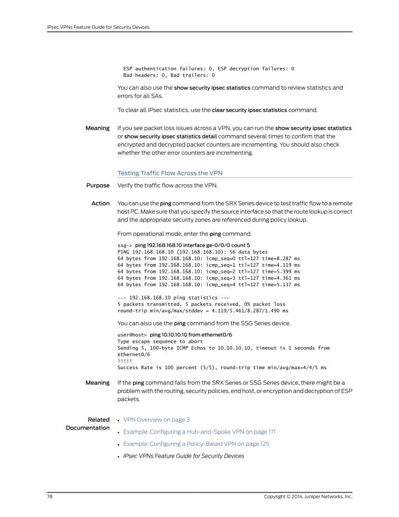
ESP authentication failures: 0, ESP decryption failures: 0 Bad headers: 0, Bad trailers: 0
You can also use the show security ipsec statistics command to review statistics and
errors for all SAs.
To clear all IPsec statistics, use the clear security ipsec statistics command.
Meaning If you see packet loss issues across a VPN, you can run the show security ipsec statistics
or show security ipsec statistics detail command several times to confirm that the
encrypted and decrypted packet counters are incrementing. You should also check
whether the other error counters are incrementing.
Testing Traffic Flow Across the VPN
Purpose Verify the traffic flow across the VPN.
Action You can use theping command from the SRX Series device to test traffic flow to a remote
host PC. Make sure that you specify the source interface so that the route lookup is correct
and the appropriate security zones are referenced during policy lookup.
From operational mode, enter the ping command.
ssg-> ping 192.168.168.10 interface ge-0/0/0 count 5PING 192.168.168.10 (192.168.168.10): 56 data bytes64 bytes from 192.168.168.10: icmp_seq=0 ttl=127 time=8.287 ms64 bytes from 192.168.168.10: icmp_seq=1 ttl=127 time=4.119 ms64 bytes from 192.168.168.10: icmp_seq=2 ttl=127 time=5.399 ms64 bytes from 192.168.168.10: icmp_seq=3 ttl=127 time=4.361 ms64 bytes from 192.168.168.10: icmp_seq=4 ttl=127 time=5.137 ms
--- 192.168.168.10 ping statistics ---5 packets transmitted, 5 packets received, 0% packet lossround-trip min/avg/max/stddev = 4.119/5.461/8.287/1.490 ms
You can also use the ping command from the SSG Series device.
user@host> ping 10.10.10.10 from ethernet0/6Type escape sequence to abortSending 5, 100-byte ICMP Echos to 10.10.10.10, timeout is 1 seconds from ethernet0/6!!!!!Success Rate is 100 percent (5/5), round-trip time min/avg/max=4/4/5 ms
Meaning If the ping command fails from the SRX Series or SSG Series device, there might be a
problem with the routing, security policies, end host, or encryption and decryption of ESP
packets.
RelatedDocumentation
VPN Overview on page 3•
• Example: Configuring a Hub-and-Spoke VPN on page 171
• Example: Configuring a Policy-Based VPN on page 125
• IPsec VPNs Feature Guide for Security Devices
Copyright © 2014, Juniper Networks, Inc.78
IPsec VPNs Feature Guide for Security Devices

Example: Configuring a Route-Based VPN for IKEv2
Supported Platforms LN Series, SRX Series
This example shows how to configure a route-based IPsec VPN to allow data to be
securely transferred between a branch office and a corporate office.
• Requirements on page 79
• Overview on page 79
• Configuration on page 81
• Verification on page 91
Requirements
This example uses the following hardware:
• SRX240 device
• SSG140 device
Before you begin, read “VPN Overview” on page 3.
Overview
In this example, you configure a route-based VPN for a branch office in Chicago, Illinois,
because you want to conserve tunnel resources but still get granular restrictions on VPN
traffic. Users in the Chicago office will use the VPN to connect to their corporate
headquarters in Sunnyvale, California.
In this example, you configure interfaces, an IPv4 default route, security zones, and
address books. Then you configure IKE Phase 1, IPsec Phase 2, a security policy, and
TCP-MSS parameters. See Table 13 on page 79 through Table 17 on page 81 for specific
configuration parameters used in this example.
Table 13: Interface, Static Route, Security Zone, and Address Book Information
Configuration ParametersNameFeature
10.10.10.1/24ge-0/0/0.0Interfaces
1.1.1.2/30ge-0/0/3.0
10.11.11.10/24st0.0 (tunnel interface)
The next hop is 1.1.1.1.0.0.0.0/0 (default route)Static routes
The next hop is st0.0.192.168.168.0/24
• All system services are allowed.
• The ge-0/0/0.0 interface is bound tothis zone.
trustSecurity zones
79Copyright © 2014, Juniper Networks, Inc.
Chapter 14: Route-Based VPN
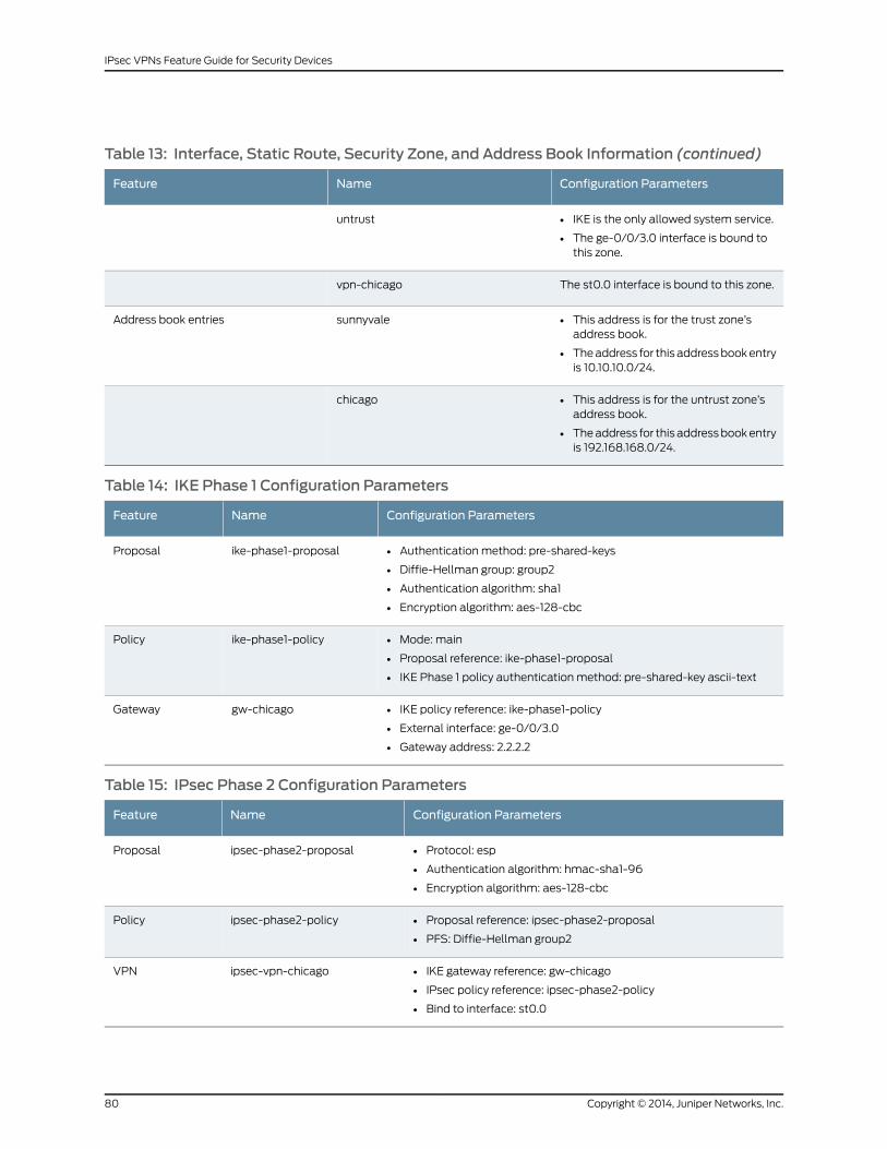
Table 13: Interface, Static Route, Security Zone, and Address Book Information (continued)
Configuration ParametersNameFeature
• IKE is the only allowed system service.
• The ge-0/0/3.0 interface is bound tothis zone.
untrust
The st0.0 interface is bound to this zone.vpn-chicago
• This address is for the trust zone’saddress book.
• The address for this address book entryis 10.10.10.0/24.
sunnyvaleAddress book entries
• This address is for the untrust zone’saddress book.
• The address for this address book entryis 192.168.168.0/24.
chicago
Table 14: IKE Phase 1 Configuration Parameters
Configuration ParametersNameFeature
• Authentication method: pre-shared-keys
• Diffie-Hellman group: group2
• Authentication algorithm: sha1
• Encryption algorithm: aes-128-cbc
ike-phase1-proposalProposal
• Mode: main
• Proposal reference: ike-phase1-proposal
• IKE Phase 1 policy authentication method: pre-shared-key ascii-text
ike-phase1-policyPolicy
• IKE policy reference: ike-phase1-policy
• External interface: ge-0/0/3.0
• Gateway address: 2.2.2.2
gw-chicagoGateway
Table 15: IPsec Phase 2 Configuration Parameters
Configuration ParametersNameFeature
• Protocol: esp
• Authentication algorithm: hmac-sha1-96
• Encryption algorithm: aes-128-cbc
ipsec-phase2-proposalProposal
• Proposal reference: ipsec-phase2-proposal
• PFS: Diffie-Hellman group2
ipsec-phase2-policyPolicy
• IKE gateway reference: gw-chicago
• IPsec policy reference: ipsec-phase2-policy
• Bind to interface: st0.0
ipsec-vpn-chicagoVPN
Copyright © 2014, Juniper Networks, Inc.80
IPsec VPNs Feature Guide for Security Devices
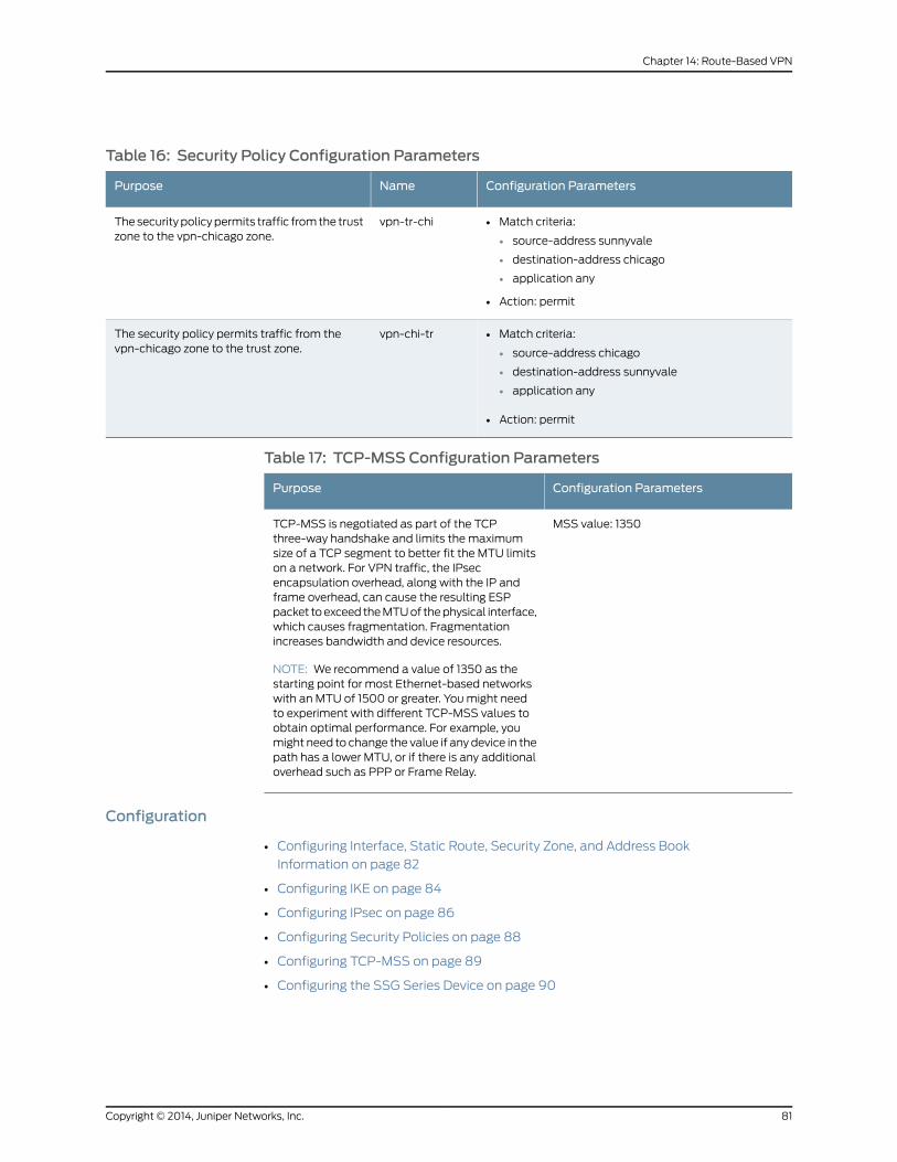
Table 16: Security Policy Configuration Parameters
Configuration ParametersNamePurpose
• Match criteria:
• source-address sunnyvale
• destination-address chicago
• application any
• Action: permit
vpn-tr-chiThe security policy permits traffic from the trustzone to the vpn-chicago zone.
• Match criteria:
• source-address chicago
• destination-address sunnyvale
• application any
• Action: permit
vpn-chi-trThe security policy permits traffic from thevpn-chicago zone to the trust zone.
Table 17: TCP-MSS Configuration Parameters
Configuration ParametersPurpose
MSS value: 1350TCP-MSS is negotiated as part of the TCPthree-way handshake and limits the maximumsize of a TCP segment to better fit the MTU limitson a network. For VPN traffic, the IPsecencapsulation overhead, along with the IP andframe overhead, can cause the resulting ESPpacket to exceed the MTU of the physical interface,which causes fragmentation. Fragmentationincreases bandwidth and device resources.
NOTE: We recommend a value of 1350 as thestarting point for most Ethernet-based networkswith an MTU of 1500 or greater. You might needto experiment with different TCP-MSS values toobtain optimal performance. For example, youmight need to change the value if any device in thepath has a lower MTU, or if there is any additionaloverhead such as PPP or Frame Relay.
Configuration
• Configuring Interface, Static Route, Security Zone, and Address Book
Information on page 82
• Configuring IKE on page 84
• Configuring IPsec on page 86
• Configuring Security Policies on page 88
• Configuring TCP-MSS on page 89
• Configuring the SSG Series Device on page 90
81Copyright © 2014, Juniper Networks, Inc.
Chapter 14: Route-Based VPN

Configuring Interface,StaticRoute, SecurityZone, andAddressBook Information
CLI QuickConfiguration
To quickly configure this section of the example, copy the following commands, paste
them into a text file, remove any line breaks, change any details necessary to match your
network configuration, and then copy and paste the commands into the CLI at the [edit]
hierarchy level.
set interfaces ge-0/0/0 unit 0 family inet address 10.10.10.1/24set interfaces ge-0/0/3 unit 0 family inet address 1.1.1.2/30set interfaces st0 unit 0 family inet address 10.11.11.10/24set routing-options static route 0.0.0.0/0 next-hop 1.1.1.1set routing-options static route 192.168.168.0/24 next-hop st0.0set security zones security-zone untrust interfaces ge-0/0/3.0set security zones security-zone untrust host-inbound-traffic system-services ikeset security zones security-zone trust interfaces ge-0/0/0.0set security zones security-zone trust host-inbound-traffic system-services allset security zones security-zone trust address-book address sunnyvale 10.10.10.0/24set security zones security-zone vpn-chicago interfaces st0.0set security zones security-zone vpn-chicago address-book address chicago192.168.168.0/24
Step-by-StepProcedure
The following example requires you to navigate various levels in the configuration
hierarchy. For instructions on how to do that, see Using the CLI Editor in Configuration
Mode.
To configure interface, static route, security zone, and address book information:
1. Configure Ethernet interface information.
[edit]user@host# set interfaces ge-0/0/0 unit 0 family inet address 10.10.10.1/24user@host# set interfaces ge-0/0/3 unit 0 family inet address 1.1.1.2/30user@host# set interfaces st0 unit 0 family inet address 10.11.11.10/24
2. Configure static route information.
[edit]user@host# set routing-options static route 0.0.0.0/0 next-hop 1.1.1.1user@host# set routing-options static route 192.168.168.0/24 next-hop st0.0
3. Configure the untrust security zone.
[edit ]user@host# edit security zones security-zone untrust
4. Assign an interface to the security zone.
[edit security zones security-zone untrust]user@host# set interfaces ge-0/0/3.0
5. Specify allowed system services for the security zone.
[edit security zones security-zone untrust]user@host# set host-inbound-traffic system-services ike
6. Configure the trust security zone.
[edit]user@host# edit security zones security-zone trust
Copyright © 2014, Juniper Networks, Inc.82
IPsec VPNs Feature Guide for Security Devices

7. Assign an interface to the trust security zone.
[edit security zones security-zone trust]user@host# set interfaces ge-0/0/0.0
8. Specify allowed system services for the trust security zone.
[edit security zones security-zone trust]user@host# set host-inbound-traffic system-services all
9. Configure the address book entry for the trust security zone.
[edit security zones security-zone trust]user@host# set address-book address sunnyvale 10.10.10.0/24
10. Configure the vpn-chicago security zone.
[edit]user@host# edit security zones security-zone vpn-chicago
11. Assign an interface to the security zone.
[edit security zones security-zone vpn-chicago]user@host# set interfaces st0.0
12. Configure the address book entry for the vpn-chicago zone.
[edit security zones security-zone vpn-chicago]user@host# set address-book address chicago 192.168.168.0/24
Results From configuration mode, confirm your configuration by entering the show interfaces,
show routing-options, and showsecurity zones commands. If the output does not display
the intended configuration, repeat the configuration instructions in this example to correct
it.
[edit]user@host# show interfacesge-0/0/0 {unit 0 {family inet {address 10.10.10.1/24;
}}
}ge-0/0/3 {unit 0 {family inet {address 1.1.1.2/30
}}
}st0{unit 0 {family inet {address 10.11.11.10/24
}}
}
83Copyright © 2014, Juniper Networks, Inc.
Chapter 14: Route-Based VPN

[edit]user@host# show routing-optionsstatic {route 0.0.0.0/0 next-hop 1.1.1.1;route 192.168.168.0/24 next-hop st0.0;
}
[edit]user@host# show security zonessecurity-zone untrust {host-inbound-traffic {system-services {ike;
}}interfaces {ge-0/0/3.0;
}}security-zone trust {address-book {address sunnyvale 10.10.10.0/24;
}host-inbound-traffic {system-services {all;
}}interfaces {ge-0/0/0.0;
}}security-zone vpn-chicago {host-inbound-traffic {address-book {address chicago 192.168.168.0/24;
}}interfaces {st0.0;
}}
If you are done configuring the device, enter commit from configuration mode.
Configuring IKE
CLI QuickConfiguration
To quickly configure this section of the example, copy the following commands, paste
them into a text file, remove any line breaks, change any details necessary to match your
network configuration, and then copy and paste the commands into the CLI at the [edit]
hierarchy level.
set security ike proposal ike-phase1-proposal authentication-method pre-shared-keysset security ike proposal ike-phase1-proposal dh-group group2set security ike proposal ike-phase1-proposal authentication-algorithm sha1set security ike proposal ike-phase1-proposal encryption-algorithm aes-128-cbc
Copyright © 2014, Juniper Networks, Inc.84
IPsec VPNs Feature Guide for Security Devices

set security ike policy ike-phase1-policy proposals ike-phase1-proposalset security ike policy ike-phase1-policy pre-shared-key ascii-text 395psksecr3tset security ike gateway gw-chicago external-interface ge-0/0/3.0set security ike gateway gw-chicago ike-policy ike-phase1-policyset security ike gateway gw-chicago address 2.2.2.2set security ike gateway gw-chicago version v2-only
Step-by-StepProcedure
The following example requires you to navigate various levels in the configuration
hierarchy. For instructions on how to do that, see Using the CLI Editor in Configuration
Mode.
To configure IKE:
1. Create the IKE Phase 1 proposal.
[edit security ike]user@host# set proposal ike-phase1-proposal
2. Define the IKE proposal authentication method.
[edit security ike proposal ike-phase1-proposal]user@host# set authentication-method pre-shared-keys
3. Define the IKE proposal Diffie-Hellman group.
[edit security ike proposal ike-phase1-proposal]user@host# set dh-group group2
4. Define the IKE proposal authentication algorithm.
[edit security ike proposal ike-phase1-proposal]user@host# set authentication-algorithm sha1
5. Define the IKE proposal encryption algorithm.
[edit security ike proposal ike-phase1-proposal]user@host# set encryption-algorithm aes-128-cbc
6. Create an IKE Phase 1 policy.
[edit security ike]user@host# set policy ike-phase1-policy
7. Specify a reference to the IKE proposal.
[edit security ike policy ike-phase1-policy]user@host# set proposals ike-phase1-proposal
8. Define the IKE Phase 1 policy authentication method.
[edit security ike policy ike-phase1-policy]user@host# set pre-shared-key ascii-text 395psksecr3t
9. Create an IKE Phase 1 gateway and define its external interface.
[edit security ike]user@host# set gateway gw-chicago external-interface ge-0/0/3.0
10. Define the IKE Phase 1 policy reference.
[edit security ike gateway gw-chicago]user@host# set ike-policy ike-phase1-policy
85Copyright © 2014, Juniper Networks, Inc.
Chapter 14: Route-Based VPN
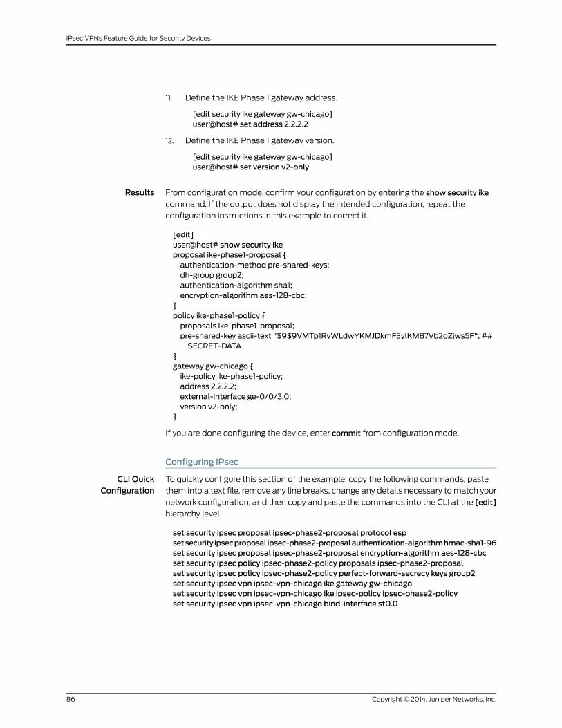
11. Define the IKE Phase 1 gateway address.
[edit security ike gateway gw-chicago]user@host# set address 2.2.2.2
12. Define the IKE Phase 1 gateway version.
[edit security ike gateway gw-chicago]user@host# set version v2-only
Results From configuration mode, confirm your configuration by entering the show security ike
command. If the output does not display the intended configuration, repeat the
configuration instructions in this example to correct it.
[edit]user@host# show security ikeproposal ike-phase1-proposal {authentication-method pre-shared-keys;dh-group group2;authentication-algorithm sha1;encryption-algorithm aes-128-cbc;
}policy ike-phase1-policy {proposals ike-phase1-proposal;pre-shared-key ascii-text "$9$9VMTp1RvWLdwYKMJDkmF3ylKM87Vb2oZjws5F"; ##SECRET-DATA
}gateway gw-chicago {ike-policy ike-phase1-policy;address 2.2.2.2;external-interface ge-0/0/3.0;version v2-only;
}
If you are done configuring the device, enter commit from configuration mode.
Configuring IPsec
CLI QuickConfiguration
To quickly configure this section of the example, copy the following commands, paste
them into a text file, remove any line breaks, change any details necessary to match your
network configuration, and then copy and paste the commands into the CLI at the [edit]
hierarchy level.
set security ipsec proposal ipsec-phase2-proposal protocol espsetsecurity ipsecproposal ipsec-phase2-proposalauthentication-algorithmhmac-sha1-96set security ipsec proposal ipsec-phase2-proposal encryption-algorithm aes-128-cbcset security ipsec policy ipsec-phase2-policy proposals ipsec-phase2-proposalset security ipsec policy ipsec-phase2-policy perfect-forward-secrecy keys group2set security ipsec vpn ipsec-vpn-chicago ike gateway gw-chicagoset security ipsec vpn ipsec-vpn-chicago ike ipsec-policy ipsec-phase2-policyset security ipsec vpn ipsec-vpn-chicago bind-interface st0.0
Copyright © 2014, Juniper Networks, Inc.86
IPsec VPNs Feature Guide for Security Devices

Step-by-StepProcedure
The following example requires you to navigate various levels in the configuration
hierarchy. For instructions on how to do that, see Using the CLI Editor in Configuration
Mode.
To configure IPsec:
1. Create an IPsec Phase 2 proposal.
[edit]user@host# set security ipsec proposal ipsec-phase2-proposal
2. Specify the IPsec Phase 2 proposal protocol.
[edit security ipsec proposal ipsec-phase2-proposal]user@host# set protocol esp
3. Specify the IPsec Phase 2 proposal authentication algorithm.
[edit security ipsec proposal ipsec-phase2-proposal]user@host# set authentication-algorithm hmac-sha1-96
4. Specify the IPsec Phase 2 proposal encryption algorithm.
[edit security ipsec proposal ipsec-phase2-proposal]user@host# set encryption-algorithm aes-128-cbc
5. Create the IPsec Phase 2 policy.
[edit security ipsec]user@host# set policy ipsec-phase2-policy
6. Specify the IPsec Phase 2 proposal reference.
[edit security ipsec policy ipsec-phase2-policy]user@host# set proposals ipsec-phase2-proposal
7. Specify IPsec Phase 2 PFS to use Diffie-Hellman group 2.
[edit security ipsec policy ipsec-phase2-policy]user@host# set perfect-forward-secrecy keys group2
8. Specify the IKE gateway.
[edit security ipsec]user@host# set vpn ipsec-vpn-chicago ike gateway gw-chicago
9. Specify the IPsec Phase 2 policy.
[edit security ipsec]user@host# set vpn ipsec-vpn-chicago ike ipsec-policy ipsec-phase2-policy
10. Specify the interface to bind.
[edit security ipsec]user@host# set vpn ipsec-vpn-chicago bind-interface st0.0
Results From configuration mode, confirm your configuration by entering the show security ipsec
command. If the output does not display the intended configuration, repeat the
configuration instructions in this example to correct it.
[edit]user@host# show security ipsec
87Copyright © 2014, Juniper Networks, Inc.
Chapter 14: Route-Based VPN

proposal ipsec-phase2-proposal {protocol esp;authentication-algorithm hmac-sha1-96;encryption-algorithm aes-128-cbc;
}policy ipsec-phase2-policy {perfect-forward-secrecy {keys group2;
}proposals ipsec-phase2-proposal;
}vpn ipsec-vpn-chicago {bind-interface st0.0;ike {gateway gw-chicago;ipsec-policy ipsec-phase2-policy;
}}
If you are done configuring the device, enter commit from configuration mode.
Configuring Security Policies
CLI QuickConfiguration
To quickly configure this section of the example, copy the following commands, paste
them into a text file, remove any line breaks, change any details necessary to match your
network configuration, and then copy and paste the commands into the CLI at the [edit]
hierarchy level.
set security policies from-zone trust to-zone vpn-chicago policy vpn-tr-chi matchsource-address sunnyvale
set security policies from-zone trust to-zone vpn-chicago policy vpn-tr-chi matchdestination-address chicago
set security policies from-zone trust to-zone vpn-chicago policy vpn-tr-chi matchapplication any
set security policies from-zone trust to-zone vpn-chicago policy vpn-tr-chi then permitset security policies from-zone vpn-chicago to-zone trust policy vpn-chi-tr matchsource-address chicago
set security policies from-zone vpn-chicago to-zone trust policy vpn-chi-tr matchdestination-address sunnyvale
set security policies from-zone vpn-chicago to-zone trust policy vpn-chi-tr matchapplication any
set security policies from-zone vpn-chicago to-zone trust policy vpn-chi-tr then permit
Step-by-StepProcedure
The following example requires you to navigate various levels in the configuration
hierarchy. For instructions on how to do that, see Using the CLI Editor in Configuration
Mode.
To configure security policies:
1. Create the security policy to permit traffic from the trust zone to the vpn-chicago
zone.
[edit security policies from-zone trust to-zone vpn-chicago]user@host# set policy vpn-tr-chi match source-address sunnyvaleuser@host# set policy vpn-tr-chi match destination-address chicago
Copyright © 2014, Juniper Networks, Inc.88
IPsec VPNs Feature Guide for Security Devices

user@host# set policy vpn-tr-chi match application anyuser@host# set policy vpn-tr-chi then permit
2. Create the security policy to permit traffic from the vpn-chicago zone to the trust
zone.
[edit security policies from-zone vpn-chicago to-zone trust]user@host# set policy vpn-chi-tr match source-address sunnyvaleuser@host# set policy vpn-chi-tr match destination-address chicagouser@host# set policy vpn-chi-tr match application anyuser@host# set policy vpn-chi-tr then permit
Results From configuration mode, confirm your configuration by entering the showsecuritypolicies
command. If the output does not display the intended configuration, repeat the
configuration instructions in this example to correct it.
[edit]user@host# show security policiesfrom-zone trust to-zone vpn-chicago {policy vpn-tr-vpn {match {source-address sunnyvale;destination-address chicago;application any;
}then {permit;
}}
}from-zone vpn-chicago to-zone trust {policy vpn-tr-vpn {match {source-address chicago;destination-address sunnyvale;application any;
}then {permit;
}}
}
If you are done configuring the device, enter commit from configuration mode.
Configuring TCP-MSS
CLI QuickConfiguration
To quickly configure this section of the example, copy the following command, paste it
into a text file, remove any line breaks, change any details necessary to match your
network configuration, and then copy and paste the command into the CLI at the [edit]
hierarchy level.
set security flow tcp-mss ipsec-vpnmss 1350
89Copyright © 2014, Juniper Networks, Inc.
Chapter 14: Route-Based VPN
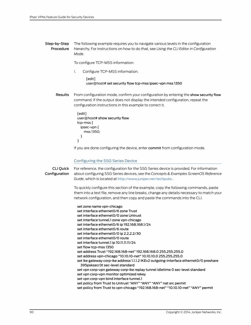
Step-by-StepProcedure
The following example requires you to navigate various levels in the configuration
hierarchy. For instructions on how to do that, see Using the CLI Editor in Configuration
Mode.
To configure TCP-MSS information:
1. Configure TCP-MSS information.
[edit]user@host# set security flow tcp-mss ipsec-vpnmss 1350
Results From configuration mode, confirm your configuration by entering the show security flow
command. If the output does not display the intended configuration, repeat the
configuration instructions in this example to correct it.
[edit]user@host# show security flowtcp-mss {ipsec-vpn {mss 1350;
}}
If you are done configuring the device, enter commit from configuration mode.
Configuring the SSG Series Device
CLI QuickConfiguration
For reference, the configuration for the SSG Series device is provided. For information
about configuring SSG Series devices, see theConcepts & Examples ScreenOSReference
Guide, which is located at http://www.juniper.net/techpubs .
To quickly configure this section of the example, copy the following commands, paste
them into a text file, remove any line breaks, change any details necessary to match your
network configuration, and then copy and paste the commands into the CLI.
set zone name vpn-chicagoset interface ethernet0/6 zone Trustset interface ethernet0/0 zone Untrustset interface tunnel.1 zone vpn-chicagoset interface ethernet0/6 ip 192.168.168.1/24set interface ethernet0/6 routeset interface ethernet0/0 ip 2.2.2.2/30set interface ethernet0/0 routeset interface tunnel.1 ip 10.11.11.11/24set flow tcp-mss 1350set address Trust “192.168.168-net” 192.168.168.0 255.255.255.0set address vpn-chicago "10.10.10-net" 10.10.10.0 255.255.255.0set ike gateway corp-ike address 1.1.1.2 IKEv2 outgoing-interface ethernet0/0 preshare395psksecr3t sec-level standard
set vpn corp-vpn gateway corp-ike replay tunnel idletime 0 sec-level standardset vpn corp-vpnmonitor optimized rekeyset vpn corp-vpn bind interface tunnel.1set policy from Trust to Untrust “ANY” “ANY” “ANY” nat src permitset policy from Trust to vpn-chicago “192.168.168-net” “10.10.10-net” “ANY” permit
Copyright © 2014, Juniper Networks, Inc.90
IPsec VPNs Feature Guide for Security Devices

set policy from vpn-chicago to Trust “10.10.10-net” “192.168.168-net” “ANY” permitset route 10.10.10.0/24 interface tunnel.1set route 0.0.0.0/0 interface ethernet0/0 gateway 2.2.2.1
Verification
To confirm that the configuration is working properly
• Verifying the IKE Phase 1 Status on page 91
• Verifying the IPsec Phase 2 Status on page 92
• Reviewing Statistics and Errors for an IPsec Security Association on page 94
• Testing Traffic Flow Across the VPN on page 94
Verifying the IKE Phase 1 Status
Purpose Verify the IKE Phase 1 status.
Action NOTE: Before starting the verification process, you need to send traffic froma host in the 10.10.10/24 network to a host in the 192.168.168/24 network.For route-basedVPNs, trafficcanbe initiatedbytheSRXSeriesdevice throughthe tunnel. We recommend that when testing IPsec tunnels, test traffic besent from a separate device on one side of the VPN to a second device onthe other side of the VPN. For example, initiate a ping from 10.10.10.10 to192.168.168.10.
From operational mode, enter the showsecurity ikesecurity-associationscommand. After
obtaining an index number from the command, use the show security ike
security-associations index index_number detail command.
user@host> show security ike security-associationsIndex Remote Address State Initiator cookie Responder cookie Mode1 2.2.2.2 UP 744a594d957dd513 1e1307db82f58387 IKEv2
user@host> show security ike security-associations index 1 detailIKE peer 2.2.2.2, Index 1, Role: Responder, State: UP Initiator cookie: 744a594d957dd513, Responder cookie: 1e1307db82f58387 Exchange type: IKEv2, Authentication method: Pre-shared-keys Local: 1.1.1.2:500, Remote: 2.2.2.2:500 Lifetime: Expires in 28570 seconds Algorithms: Authentication : sha1 Encryption : aes-cbc (128 bits) Pseudo random function: hmac-sha1 Traffic statistics: Input bytes : 852 Output bytes : 940 Input packets : 5 Output packets : 5 Flags: Caller notification sent IPSec security associations: 1 created, 0 deleted
91Copyright © 2014, Juniper Networks, Inc.
Chapter 14: Route-Based VPN

Meaning The show security ike security-associations command lists all active IKE Phase 1 SAs. If
no SAs are listed, there was a problem with Phase 1 establishment. Check the IKE policy
parameters and external interface settings in your configuration.
If SAs are listed, review the following information:
• Index—This value is unique for each IKE SA, which you can use in the show security ike
security-associations index detail command to get more information about the SA.
• Remote Address—Verify that the remote IP address is correct.
• State
• UP—The Phase 1 SA has been established.
• DOWN—There was a problem establishing the Phase 1 SA.
• Mode—Verify that the correct mode is being used.
Verify that the following are correct in your configuration:
• External interfaces (the interface must be the one that receives IKE packets).
• IKE policy parameters.
• Preshared key information.
• Phase 1 proposal parameters (must match on both peers).
The show security ike security-associations index 1 detail command lists additional
information about the SA with an index number of 1:
• Authentication and encryption algorithms used
• Phase 1 lifetime
• Traffic statistics (can be used to verify that traffic is flowing properly in both directions)
• Role information
NOTE: Troubleshooting is best performedon the peer using the responderrole.
• Initiator and responder information
• Number of IPsec SAs created
Verifying the IPsec Phase 2 Status
Purpose Verify the IPsec Phase 2 status.
Copyright © 2014, Juniper Networks, Inc.92
IPsec VPNs Feature Guide for Security Devices

Action From operational mode, enter the show security ipsec security-associations command.
After obtaining an index number from the command, use the show security ipsec
security-associations index index_number detail command.
user@host> show security ipsec security-associations total configured sa: 2 ID Gateway Port Algorithm SPI Life:sec/kb Mon vsys <16384 2.2.2.2 500 ESP:aes-128/sha1 76d64d1d 3363/ unlim - 0 >16384 2.2.2.2 500 ESP:aes-128/sha1 a1024ee2 3363/ unlim - 0
user@host> show security ipsec security-associations index 16384 detail Virtual-system: Root Local Gateway: 1.1.1.2, Remote Gateway: 2.2.2.2 Local Identity: ipv4_subnet(any:0,[0..7]=10.10.10.0/24) Remote Identity: ipv4_subnet(any:0,[0..7]=192.168.168.0/24) Version: IKEv2
DF-bit: clear
Direction: inbound, SPI: 1993755933, AUX-SPI: 0 Hard lifetime: Expires in 3352 seconds Lifesize Remaining: Unlimited Soft lifetime: Expires in 2775 seconds Mode: tunnel, Type: dynamic, State: installed, VPN Monitoring: - Protocol: ESP, Authentication: hmac-sha1-96, Encryption: aes-cbc (128 bits)
Anti-replay service: enabled, Replay window size: 32
Direction: outbound, SPI: 2701283042, AUX-SPI: 0 Hard lifetime: Expires in 3352 seconds Lifesize Remaining: Unlimited Soft lifetime: Expires in 2775 seconds Mode: tunnel, Type: dynamic, State: installed, VPN Monitoring: - Protocol: ESP, Authentication: hmac-sha1-96, Encryption: aes-cbc (128 bits) Anti-replay service: enabled, Replay window size: 32
Meaning The output from the showsecurity ipsecsecurity-associationscommand lists the following
information:
• The ID number is 16384. Use this value with the showsecurity ipsecsecurity-associations
index command to get more information about this particular SA.
• There is one IPsec SA pair using port 500.
• The SPIs, lifetime (in seconds), and usage limits (or lifesize in KB) are shown for both
directions. The 3363/ unlim value indicates that the Phase 2 lifetime expires in 3363
seconds, and that no lifesize has been specified, which indicates that it is unlimited.
Phase 2 lifetime can differ from Phase 1 lifetime, because Phase 2 is not dependent
on Phase 1 after the VPN is up.
• The vsys is the root system, and it is always listed as 0.
• The IKEv2 allows connections from a version 2 peer and will initiate a version 2
negotiation.
The output from the showsecurity ipsecsecurity-associations index16384detailcommand
lists the following information:
93Copyright © 2014, Juniper Networks, Inc.
Chapter 14: Route-Based VPN

• The local identity and remote identity make up the proxy ID for the SA.
A proxy ID mismatch is one of the most common causes for a Phase 2 failure. If no
IPsec SA is listed, confirm that Phase 2 proposals, including the proxy ID settings, are
correct for both peers. For route-based VPNs, the default proxy ID is local=0.0.0.0/0,
remote=0.0.0.0/0, and service=any. Issues can occur with multiple route-based VPNs
from the same peer IP. In this case, a unique proxy ID for each IPsec SA must be
specified. For some third-party vendors, the proxy ID must be manually entered to
match.
• Another common reason for Phase 2 failure is not specifying the ST interface binding.
If IPsec cannot complete, check the kmd log or set traceoptions.
Reviewing Statistics and Errors for an IPsec Security Association
Purpose Review ESP and authentication header counters and errors for an IPsec SA.
Action From operational mode, enter the show security ipsec statistics index index_number
command, using the index number of the VPN for which you want to see statistics.
user@host> show security ipsec statistics index 16384ESP Statistics: Encrypted bytes: 920 Decrypted bytes: 6208 Encrypted packets: 5 Decrypted packets: 87AH Statistics: Input bytes: 0 Output bytes: 0 Input packets: 0 Output packets: 0Errors: AH authentication failures: 0, Replay errors: 0 ESP authentication failures: 0, ESP decryption failures: 0 Bad headers: 0, Bad trailers: 0
You can also use the show security ipsec statistics command to review statistics and
errors for all SAs.
To clear all IPsec statistics, use the clear security ipsec statistics command.
Meaning If you see packet loss issues across a VPN, you can run the show security ipsec statistics
or show security ipsec statistics detail command several times to confirm that the
encrypted and decrypted packet counters are incrementing. You should also check that
the other error counters are incrementing.
Testing Traffic Flow Across the VPN
Purpose Verify the traffic flow across the VPN.
Action You can use theping command from the SRX Series device to test traffic flow to a remote
host PC. Make sure that you specify the source interface so that the route lookup is correct
and the appropriate security zones are referenced during policy lookup.
Copyright © 2014, Juniper Networks, Inc.94
IPsec VPNs Feature Guide for Security Devices

From operational mode, enter the ping command.
ssg-> ping 192.168.168.10 interface ge-0/0/0 count 5PING 192.168.168.10 (192.168.168.10): 56 data bytes64 bytes from 192.168.168.10: icmp_seq=0 ttl=127 time=8.287 ms64 bytes from 192.168.168.10: icmp_seq=1 ttl=127 time=4.119 ms64 bytes from 192.168.168.10: icmp_seq=2 ttl=127 time=5.399 ms64 bytes from 192.168.168.10: icmp_seq=3 ttl=127 time=4.361 ms64 bytes from 192.168.168.10: icmp_seq=4 ttl=127 time=5.137 ms
--- 192.168.168.10 ping statistics ---5 packets transmitted, 5 packets received, 0% packet lossround-trip min/avg/max/stddev = 4.119/5.461/8.287/1.490 ms
You can also use the ping command from the SSG Series device.
user@host> ping 10.10.10.10 from ethernet0/6Type escape sequence to abortSending 5, 100-byte ICMP Echos to 10.10.10.10, timeout is 1 seconds from ethernet0/6!!!!!Success Rate is 100 percent (5/5), round-trip time min/avg/max=4/4/5 ms
Meaning If the ping command fails from the SRX Series or SSG Series device, there might be a
problem with the routing, security policies, end host, or encryption and decryption of ESP
packets.
RelatedDocumentation
VPN Overview on page 3•
• Example: Configuring a Hub-and-Spoke VPN on page 171
• Example: Configuring a Policy-Based VPN on page 125
• Understanding Internet Key Exchange Version 2 on page 22
• IPsec VPNs Feature Guide for Security Devices
Example: Configuring a Route-Based VPNwith Only the Responder Behind a NATDevice
Supported Platforms J Series, LN Series, SRX Series
This example shows how to configure a route-based VPN with a responder behind a NAT
device to allow data to be securely transferred between a branch office and the corporate
office.
• Requirements on page 95
• Overview on page 96
• Configuration on page 101
• Verification on page 114
Requirements
Before you begin, read “VPN Overview” on page 3.
95Copyright © 2014, Juniper Networks, Inc.
Chapter 14: Route-Based VPN
Overview
In this example, you configure a route-based VPN for a branch office in Chicago, Illinois,
because you want to conserve tunnel resources but still get granular restrictions on VPN
traffic. Users in the Chicago office will use the VPN to connect to their corporate
headquarters in Sunnyvale, California.
Figure 14 on page 97 shows an example of a topology for route-based VPN with only the
responder behind a NAT device.
Copyright © 2014, Juniper Networks, Inc.96
IPsec VPNs Feature Guide for Security Devices

Figure 14: Route-Based VPN Topology with Only the Responder Behinda NAT Device
Trust zone
32.1.1.2
Untrustzone
Internet
Trust zone
ge-0/0/2.071.1.1.1/24
ge-0/0/3.032.1.1.1/24
st0.131.1.1.1/24
SRX Series device
Chicago(initiator)
33.1.1.2
ge-0/0/3.033.1.1.1/24SRX Series device
Sunnyvale(responder)
st0.131.1.1.2/24
ge-0/0/1.01.0.0.1/24
ge-0/0/2.071.1.1.2/24
ge-0/0/1.01.0.0.2/24
g034
203
97Copyright © 2014, Juniper Networks, Inc.
Chapter 14: Route-Based VPN

In this example, you configure interfaces, routing options, security zones, and security
policies for both an initiator in Chicago and a responder in Sunnyvale. Then you configure
IKE Phase 1 and IPsec Phase 2 parameters.
Packets sent from the initiator with a destination address 1.1.1.1/32 are translated to the
destination address 71.1.1.1/32 on the NAT device.
See Table 18 on page 98 through Table 21 on page 99 for specific configuration parameters
used for the initiator in the examples.
Table 18: Interface, Routing Options, and Security Zones for the Initiator
Configuration ParametersNameFeature
1.0.0.1/24ge-0/0/1Interfaces
33.1.1.1/24ge-0/0/3
31.1.1.2/24st0 (tunnel interface)
The next hop is 31.1.1.1.32.1.1.0/24 (default route)Static routes
The next hop is 1.0.0.2.1.1.1.1/32
• All system services are allowed.
• All protocols are allowed.
• The ge-0/0/1.0 and the st0.1 interfacesare bound to this zone.
untrustSecurity zones
• All system services are allowed.
• All protocols are allowed.
• The ge-0/0/3.0 interface is bound tothis zone.
trust
Table 19: IKE Phase 1 Configuration Parameters for the Initiator
Configuration ParametersNameFeature
• Authentication method: pre-shared-keys
• Diffie-Hellman group: group2
• Authentication algorithm: sha1
• Encryption algorithm: 3des-cbc
ike_propProposal
• Mode: main
• Proposal reference: ike_prop
• IKE Phase 1 policy authentication method: pre-shared-key ascii-text
ike_polPolicy
Copyright © 2014, Juniper Networks, Inc.98
IPsec VPNs Feature Guide for Security Devices
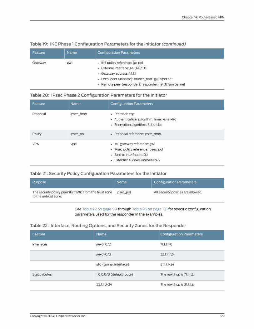
Table 19: IKE Phase 1 Configuration Parameters for the Initiator (continued)
Configuration ParametersNameFeature
• IKE policy reference: ike_pol
• External interface: ge-0/0/1.0
• Gateway address: 1.1.1.1
• Local peer (initiator): [email protected]
• Remote peer (responder): [email protected]
gw1Gateway
Table 20: IPsec Phase 2 Configuration Parameters for the Initiator
Configuration ParametersNameFeature
• Protocol: esp
• Authentication algorithm: hmac-sha1-96
• Encryption algorithm: 3des-cbc
ipsec_propProposal
• Proposal reference: ipsec_propipsec_polPolicy
• IKE gateway reference: gw1
• IPsec policy reference: ipsec_pol
• Bind to interface: st0.1
• Establish tunnels immediately
vpn1VPN
Table 21: Security Policy Configuration Parameters for the Initiator
Configuration ParametersNamePurpose
All security policies are allowed.ipsec_polThe security policy permits traffic from the trust zoneto the untrust zone.
See Table 22 on page 99 through Table 25 on page 101 for specific configuration
parameters used for the responder in the examples.
Table 22: Interface, Routing Options, and Security Zones for the Responder
Configuration ParametersNameFeature
71.1.1.1/8ge-0/0/2Interfaces
32.1.1.1/24ge-0/0/3
31.1.1.1/24st0 (tunnel interface)
The next hop is 71.1.1.2.1.0.0.0/8 (default route)Static routes
The next hop is 31.1.1.2.33.1.1.0/24
99Copyright © 2014, Juniper Networks, Inc.
Chapter 14: Route-Based VPN

Table 22: Interface, Routing Options, and Security Zones for the Responder (continued)
Configuration ParametersNameFeature
• All system services are allowed.
• All protocols are allowed.
• The ge-0/0/2.0 and the st0.1 interfacesare bound to this zone.
untrustSecurity zones
• All system services are allowed.
All protocols are allowed.
• The ge-0/0/3.0 interface is bound tothis zone.
trust
Table 23: IKE Phase 1 Configuration Parameters for the Responder
Configuration ParametersNameFeature
• Authentication method: pre-shared-keys
• Diffie-Hellman group: group2
• Authentication algorithm: sha1
• Encryption algorithm: 3des-cbc
ike_propProposal
• Mode: main
• Proposal reference: ike_prop
• IKE Phase 1 policy authentication method: pre-shared-key ascii-text
ike_polPolicy
• IKE policy reference: ike_pol
• External interface: ge-0/0/2.0
• Gateway address: 1.0.0.1
• Local peer (responder): [email protected]
• Remote peer (initiator): [email protected]
gw1Gateway
Table 24: IPsec Phase 2 Configuration Parameters for the Responder
Configuration ParametersNameFeature
• Protocol: esp
• Authentication algorithm: hmac-sha1-96
• Encryption algorithm: 3des-cbc
ipsec_propProposal
• Proposal reference: ipsec_propipsec_polPolicy
• IKE gateway reference: gw1
• IPsec policy reference: ipsec_pol
• Bind to interface: st0.1
• Establish tunnels immediately
vpn1VPN
Copyright © 2014, Juniper Networks, Inc.100
IPsec VPNs Feature Guide for Security Devices

Table 25: Security Policy Configuration Parameters for the Responder
Configuration ParametersNamePurpose
All security policies are allowed.ipsec_polThe security policy permits traffic from the trust zoneto the untrust zone.
Configuration
• Configuring Interface, Routing Options, Security Zones, and Security Policies for the
Initiator on page 101
• Configuring IKE for the Initiator on page 104
• Configuring IPsec for the Initiator on page 106
• Configuring Interfaces, Routing Options, Security Zones, and Security Policies for the
Responder on page 107
• Configuring IKE for the Responder on page 110
• Configuring IPsec for the Responder on page 112
Configuring Interface, Routing Options, Security Zones, and Security Policies forthe Initiator
CLI QuickConfiguration
To quickly configure this section of the example, copy the following commands, paste
them into a text file, remove any line breaks, change any details necessary to match your
network configuration, and then copy and paste the commands into the CLI at the [edit]
hierarchy level.
set interfaces ge-0/0/1 unit 0 family inet address 1.0.0.1/24set interfaces ge-0/0/3 unit 0 family inet address 33.1.1.1/24set interfaces st0 unit 1 family inet address 31.1.1.2/24set routing-options static route 32.1.1.0/24 next-hop 31.1.1.1set routing-options static route 1.1.1.1/32 next-hop 1.0.0.2set security zones security-zone untrust host-inbound-traffic system-services allset security zones security-zone untrust host-inbound-traffic protocols allset security zones security-zone untrust interfaces st0.1set security zones security-zone untrust interfaces ge-0/0/1.0set security zones security-zone trust host-inbound-traffic system-services allset security zones security-zone trust host-inbound-traffic protocols allset security zones security-zone trust interfaces ge-0/0/3.0set security policies default-policy permit-all
Step-by-StepProcedure
The following example requires you to navigate various levels in the configuration
hierarchy. For instructions on how to do that, see Using the CLI Editor in Configuration
Mode.
To configure interface, static route, security zone, and security policy information:
1. Configure Ethernet interface information.
[edit]user@host# set interfaces ge-0/0/1 unit 0 family inet address 1.0.0.1/24user@host# set interfaces ge-0/0/3 unit 0 family inet address 33.1.1.1/24
101Copyright © 2014, Juniper Networks, Inc.
Chapter 14: Route-Based VPN

user@host# set interfaces st0 unit 1 family inet address 31.1.1.2/24
2. Configure static route information.
[edit]user@host# set routing-options static route 32.1.1.0/24 next-hop 31.1.1.1user@host# set routing-options static route 1.1.1.1/32 next-hop 1.0.0.2
3. Configure the untrust security zone.
[edit ]user@host#set security zonessecurity-zoneuntrusthost-inbound-trafficprotocolsall
4. Assign interfaces to the untrust security zone.
[edit security zones security-zone untrust]user@host# set interfaces ge-0/0/1.0user@host# set interfaces st0.1
5. Specify allowed system services for the untrust security zone.
[edit security zones security-zone untrust]user@host# set host-inbound-traffic system-services all
6. Configure the trust security zone.
[edit]user@host# set security zones security-zone trust host-inbound-traffic protocolsall
7. Assign an interface to the trust security zone.
[edit security zones security-zone trust]user@host# set interfaces ge-0/0/3.0
8. Specify allowed system services for the trust security zone.
[edit security zones security-zone trust]user@host# set host-inbound-traffic system-services all
9. Specify security policies to permit site-to-site traffic.
[edit security policies]user@host# set default-policy permit-all
Results From configuration mode, confirm your configuration by entering the show interfaces,
show routing-options, show security zones, and show security policiescommands. If the
output does not display the intended configuration, repeat the instructions in this example
to correct the configuration.
[edit]user@host# show interfacesge-0/0/1 {unit 0 {family inet {address 1.0.0.1/24;
}}
}ge-0/0/3 {
Copyright © 2014, Juniper Networks, Inc.102
IPsec VPNs Feature Guide for Security Devices

unit 0 {family inet {address 33.1.1.1/24;
}}
}st0 {unit 1 {family inet {address 31.1.1.2/24
}}
}
[edit]user@host# show routing-optionsstatic {route 32.1.1.0/24 next-hop 31.1.1.1;route 1.1.1.1/32 next-hop 1.0.0.2;
}
[edit]user@host# show security zonessecurity-zone untrust {host-inbound-traffic {system-services {all;
}}interfaces {st0.1;ge-0/0/1.0;
}}security-zone trust {host-inbound-traffic {system-services {all;
}protocols {all;}
}interfaces {ge-0/0/3.0;}[edit]
user@host# show security policiesdefault policy {permit all;
}
If you are done configuring the device, enter commit from configuration mode.
103Copyright © 2014, Juniper Networks, Inc.
Chapter 14: Route-Based VPN

Configuring IKE for the Initiator
CLI QuickConfiguration
To quickly configure this section of the example, copy the following commands, paste
them into a text file, remove any line breaks, change any details necessary to match your
network configuration, and then copy and paste the commands into the CLI at the [edit]
hierarchy level.
set security ike proposal ike_prop authentication-method pre-shared-keysset security ike proposal ike_prop dh-group group2set security ike proposal ike_prop authentication-algorithm sha1set security ike proposal ike_prop encryption-algorithm 3des-cbcset security ike policy ike_pol modemainset security ike policy ike_pol proposals ike_propset security ike policy ike_pol pre-shared-key ascii-text “juniper”set security ike gateway gw1 ike-policy ike_polset security ike gateway gw1 address 1.1.1.1set security ike gateway gw1 local-identity user-at-hostname [email protected] security ike gateway gw1 remote-identity [email protected]
set security ike gateway gw1 external-interface ge-0/0/1.0
Step-by-StepProcedure
The following example requires you to navigate various levels in the configuration
hierarchy. For instructions on how to do that, see Using the CLI Editor in Configuration
Mode.
To configure IKE:
1. Create the IKE Phase 1 proposal.
[edit security ike]user@host# set proposal ike_prop
2. Define the IKE proposal authentication method.
[edit security ike proposal ike_prop]user@host# set authentication-method pre-shared-keys
3. Define the IKE proposal Diffie-Hellman group.
[edit security ike proposal ike_prop]user@host# set dh-group group2
4. Define the IKE proposal authentication algorithm.
[edit security ike proposal ike_prop]user@host# set authentication-algorithm sha1
5. Define the IKE proposal encryption algorithm.
[edit security ike proposal ike_prop]user@host# set encryption-algorithm 3des-cbc
6. Create an IKE Phase 1 policy.
[edit security ike]user@host# set policy ike_pol
7. Set the IKE Phase 1 policy mode.
Copyright © 2014, Juniper Networks, Inc.104
IPsec VPNs Feature Guide for Security Devices
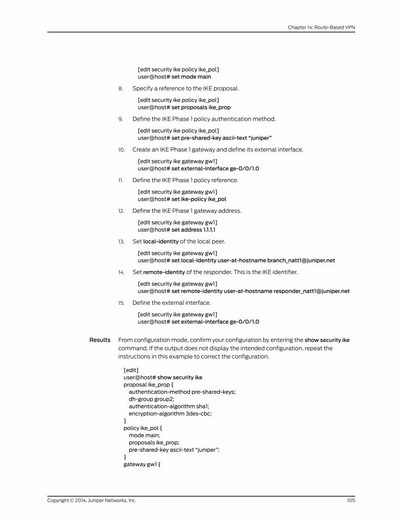
[edit security ike policy ike_pol]user@host# setmodemain
8. Specify a reference to the IKE proposal.
[edit security ike policy ike_pol]user@host# set proposals ike_prop
9. Define the IKE Phase 1 policy authentication method.
[edit security ike policy ike_pol]user@host# set pre-shared-key ascii-text “juniper”
10. Create an IKE Phase 1 gateway and define its external interface.
[edit security ike gateway gw1]user@host# set external-interface ge-0/0/1.0
11. Define the IKE Phase 1 policy reference.
[edit security ike gateway gw1]user@host# set ike-policy ike_pol
12. Define the IKE Phase 1 gateway address.
[edit security ike gateway gw1]user@host# set address 1.1.1.1
13. Set local-identity of the local peer.
[edit security ike gateway gw1]user@host# set local-identity user-at-hostname [email protected]
14. Set remote-identity of the responder. This is the IKE identifier.
[edit security ike gateway gw1]user@host# set remote-identity user-at-hostname [email protected]
15. Define the external interface.
[edit security ike gateway gw1]user@host# set external-interface ge-0/0/1.0
Results From configuration mode, confirm your configuration by entering the show security ike
command. If the output does not display the intended configuration, repeat the
instructions in this example to correct the configuration.
[edit]user@host# show security ikeproposal ike_prop {authentication-method pre-shared-keys;dh-group group2;authentication-algorithm sha1;encryption-algorithm 3des-cbc;
}policy ike_pol {modemain;proposals ike_prop;pre-shared-key ascii-text “juniper”;
}gateway gw1 {
105Copyright © 2014, Juniper Networks, Inc.
Chapter 14: Route-Based VPN
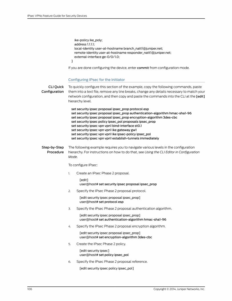
ike-policy ike_poly;address 1.1.1.1;local-identity user-at-hostname [email protected];remote-identity user-at-hostname [email protected];external-interface ge-0/0/1.0;
}
If you are done configuring the device, enter commit from configuration mode.
Configuring IPsec for the Initiator
CLI QuickConfiguration
To quickly configure this section of the example, copy the following commands, paste
them into a text file, remove any line breaks, change any details necessary to match your
network configuration, and then copy and paste the commands into the CLI at the [edit]
hierarchy level.
set security ipsec proposal ipsec_prop protocol espset security ipsec proposal ipsec_prop authentication-algorithm hmac-sha1-96set security ipsec proposal ipsec_prop encryption-algorithm 3des-cbcset security ipsec policy ipsec_pol proposals ipsec_propset security ipsec vpn vpn1 bind-interface st0.1set security ipsec vpn vpn1 ike gateway gw1set security ipsec vpn vpn1 ike ipsec-policy ipsec_polset security ipsec vpn vpn1 establish-tunnels immediately
Step-by-StepProcedure
The following example requires you to navigate various levels in the configuration
hierarchy. For instructions on how to do that, see Using the CLI Editor in Configuration
Mode.
To configure IPsec:
1. Create an IPsec Phase 2 proposal.
[edit]user@host# set security ipsec proposal ipsec_prop
2. Specify the IPsec Phase 2 proposal protocol.
[edit security ipsec proposal ipsec_prop]user@host# set protocol esp
3. Specify the IPsec Phase 2 proposal authentication algorithm.
[edit security ipsec proposal ipsec_prop]user@host# set authentication-algorithm hmac-sha1-96
4. Specify the IPsec Phase 2 proposal encryption algorithm.
[edit security ipsec proposal ipsec_prop]user@host# set encryption-algorithm 3des-cbc
5. Create the IPsec Phase 2 policy.
[edit security ipsec]user@host# set policy ipsec_pol
6. Specify the IPsec Phase 2 proposal reference.
[edit security ipsec policy ipsec_pol]
Copyright © 2014, Juniper Networks, Inc.106
IPsec VPNs Feature Guide for Security Devices

user@host# set proposals ipsec_prop
7. Specify the IKE gateway.
[edit security ipsec]user@host# set vpn vpn1 ike gateway gw1
8. Specify the IPsec Phase 2 policy.
[edit security ipsec]user@host# set vpn vpn1 ike ipsec-policy ipsec_pol
9. Specify the interface to bind.
[edit security ipsec]user@host# set vpn vpn1 bind-interface st0.1
10. Specify that the tunnel be brought up immediately without waiting for a verification
packet to be sent.
[edit security ipsec]user@host# set vpn vpn1 establish-tunnels immediately
Results From configuration mode, confirm your configuration by entering the show security ipsec
command. If the output does not display the intended configuration, repeat the
instructions in this example to correct the configuration.
[edit]user@host# show security ipsecproposal ipsec_prop {protocol esp;authentication-algorithm hmac-sha1-96;encryption-algorithm 3des-cbc;
}policy ipsec_pol {proposals ipsec_prop;}vpn vpn1 {bind-interface st0.1;ike {gateway gw1;ipsec-policy ipsec_pol;}
establish-tunnels immediately;}proposals ipsec_prop;}
}
If you are done configuring the device, enter commit from configuration mode.
Configuring Interfaces, RoutingOptions, Security Zones, andSecurity Policies forthe Responder
CLI QuickConfiguration
To quickly configure this section of the example, copy the following commands, paste
them into a text file, remove any line breaks, change any details necessary to match your
107Copyright © 2014, Juniper Networks, Inc.
Chapter 14: Route-Based VPN

network configuration, and then copy and paste the commands into the CLI at the [edit]
hierarchy level.
set interfaces ge-0/0/2 unit 0 family inet address 71.1.1.1/8set interfaces ge-0/0/3 unit 0 family inet address 32.1.1.1/24set interfaces st0 unit 1 family inet address 31.1.1.1/24set routing-options static route 1.0.0.0/8 next-hop 71.1.1.2set routing-options static route 33.1.1.0/24 next-hop 31.1.1.2set security zones security-zone untrust host-inbound-traffic system-services allset security zones security-zone untrust host-inbound-traffic protocols allset security zones security-zone untrust interfaces ge-0/0/2.0set security zones security-zone untrust interfaces st0.1set security zones security-zone trust host-inbound-traffic system-services allset security zones security-zone trust host-inbound-traffic protocols allset security zones security-zone trust interfaces ge-0/0/3.0set security policies default-policy permit-all
Step-by-StepProcedure
The following example requires you to navigate various levels in the configuration
hierarchy. For instructions on how to do that, see Using the CLI Editor in Configuration
Mode.
To configure interface, static route, security zones, policies and gateways:
1. Configure Ethernet interface information.
[edit]user@host# set interfaces ge-0/0/2 unit 0 family inet address 71.1.1.1/8user@host# set interfaces ge-0/0/3 unit 0 family inet address 32.1.1.1/24user@host# set interfaces st0 unit 1 family inet address 31.1.1.1/24
2. Configure static route information.
[edit]user@host# set routing-options static route 1.0.0.0/8 next-hop 71.1.1.2user@host# set routing-options static route 33.1.1.0/24 next-hop 31.1.1.2
3. Configure the untrust security zone.
[edit ]user@host#set security zonessecurity-zoneuntrusthost-inbound-trafficprotocolsall
4. Assign interfaces to the untrust security zone.
[edit security zones security-zone untrust]user@host# set security zones security-zone untrust interfaces ge-0/0/2.0user@host# set security zones security-zone untrust interfaces st0.1
5. Specify allowed system services for the untrust security zone.
[edit security zones security-zone untrust]user@host# set host-inbound-traffic system-services all
6. Configure the trust security zone.
[edit]user@host# set security zones security-zone trust host-inbound-traffic protocolsall
7. Assign an interface to the trust security zone.
Copyright © 2014, Juniper Networks, Inc.108
IPsec VPNs Feature Guide for Security Devices

[edit security zones security-zone trust]user@host# set interfaces ge-0/0/3.0
8. Specify allowed system services for the trust security zone.
[edit security zones security-zone trust]user@host# set host-inbound-traffic system-services all
9. Specify security policies to permit site-to-site traffic.
[edit security policies]user@host# set default-policy permit-all
Results From configuration mode, confirm your configuration by entering the show interfaces,
show routing-options, show security zones, and show security policies commands. If the
output does not display the intended configuration, repeat the instructions in this example
to correct the configuration.
[edit]user@host# show interfacesge-0/0/2 {unit 0 {family inet {address 71.1.1.1/8;
}}
}ge-0/0/3 {unit 0 {family inet {address 32.1.1.1/24;
}}
}st0 {unit 1 {family inet {address 31.1.1.1/24
}}
}
[edit]user@host# show routing-optionsstatic {route 1.0.0.0/8 next-hop 71.1.1.2;route 33.1.1.0/24 next-hop 31.1.1.2;
}
[edit]user@host# show security zonessecurity-zone untrust {host-inbound-traffic {system-services {all;protocols {all;
109Copyright © 2014, Juniper Networks, Inc.
Chapter 14: Route-Based VPN
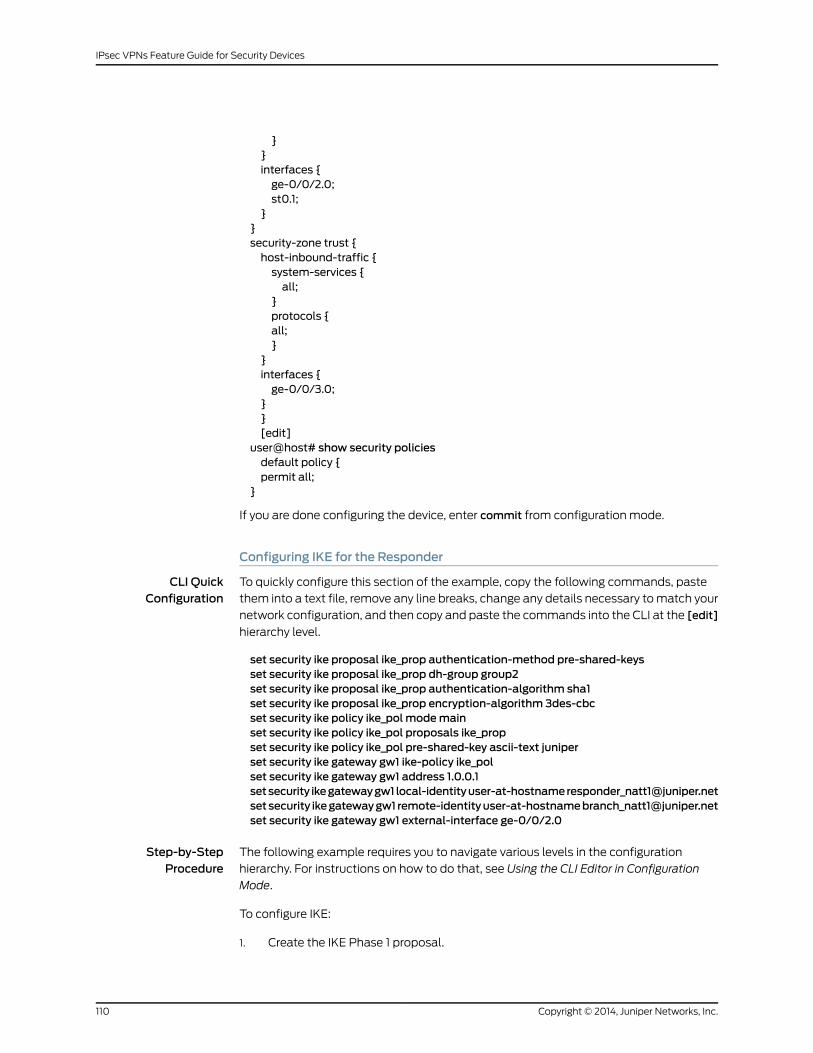
}}interfaces {ge-0/0/2.0;st0.1;
}}security-zone trust {host-inbound-traffic {system-services {all;
}protocols {all;}
}interfaces {ge-0/0/3.0;
}}[edit]
user@host# show security policiesdefault policy {permit all;
}
If you are done configuring the device, enter commit from configuration mode.
Configuring IKE for the Responder
CLI QuickConfiguration
To quickly configure this section of the example, copy the following commands, paste
them into a text file, remove any line breaks, change any details necessary to match your
network configuration, and then copy and paste the commands into the CLI at the [edit]
hierarchy level.
set security ike proposal ike_prop authentication-method pre-shared-keysset security ike proposal ike_prop dh-group group2set security ike proposal ike_prop authentication-algorithm sha1set security ike proposal ike_prop encryption-algorithm 3des-cbcset security ike policy ike_pol modemainset security ike policy ike_pol proposals ike_propset security ike policy ike_pol pre-shared-key ascii-text juniperset security ike gateway gw1 ike-policy ike_polset security ike gateway gw1 address 1.0.0.1setsecurity ikegatewaygw1 local-identityuser-at-hostnameresponder_natt1@juniper.netsetsecurity ikegatewaygw1 [email protected] security ike gateway gw1 external-interface ge-0/0/2.0
Step-by-StepProcedure
The following example requires you to navigate various levels in the configuration
hierarchy. For instructions on how to do that, see Using the CLI Editor in Configuration
Mode.
To configure IKE:
1. Create the IKE Phase 1 proposal.
Copyright © 2014, Juniper Networks, Inc.110
IPsec VPNs Feature Guide for Security Devices

[edit security ike]user@host# set proposal ike_prop
2. Define the IKE proposal authentication method.
[edit security ike proposal ike_prop]user@host# set authentication-method pre-shared-keys
3. Define the IKE proposal Diffie-Hellman group.
[edit security ike proposal ike_prop]user@host# set dh-group group2
4. Define the IKE proposal authentication algorithm.
[edit security ike proposal ike_prop]user@host# set authentication-algorithm sha1
5. Define the IKE proposal encryption algorithm.
[edit security ike proposal ike_prop]user@host# set encryption-algorithm 3des-cbc
6. Create an IKE Phase 1 policy
[edit security ike]user@host# set policy ike_pol
7. Set the IKE Phase 1 policy mode.
[edit security ike policy ike_pol]user@host# setmodemain
8. Specify a reference to the IKE proposal.
[edit security ike policy ike_pol]user@host# set proposals ike_prop
9. Define the IKE Phase 1 policy authentication method.
[edit security ike policy ike_pol]user@host# set pre-shared-key ascii-text “juniper”
10. Create an IKE Phase 1 gateway and define its external interface.
[edit security ike gateway gw1]user@host# set external-interface ge-0/0/2.0
11. Define the IKE Phase 1 policy reference.
[edit security ike gateway gw1]user@host# set ike-policy ike_pol
12. Define the IKE Phase 1 gateway address.
[edit security ike gateway gw1]user@host# set address 1.0.0.1
13. Set local-identity of the responder.
[edit security ike gateway gw1]user@host# set local-identity user-at-hostname [email protected]
14. Set remote-identity of the responder. This is the IKE identifier.
[edit security ike gateway gw1]
111Copyright © 2014, Juniper Networks, Inc.
Chapter 14: Route-Based VPN

user@host# set remote-identity user-at-hostname [email protected]
Results From configuration mode, confirm your configuration by entering the show security ike
command. If the output does not display the intended configuration, repeat the
instructions in this example to correct the configuration.
[edit]user@host# show security ikeproposal ike_prop {authentication-method pre-shared-keys;dh-group group2;authentication-algorithm sha1;encryption-algorithm 3des-cbc;
}policy ike_pol {modemain;proposals ike_prop;pre-shared-key ascii-text juniper;
}gateway gw1 {ike-policy ike_pol;address 1.0.0.1;local-identity user-at-hostname "[email protected]";remote-identity user-at-hostname "[email protected]";external-interface ge-0/0/2.0;
}
If you are done configuring the device, enter commit from configuration mode.
Configuring IPsec for the Responder
CLI QuickConfiguration
To quickly configure this section of the example, copy the following commands, paste
them into a text file, remove any line breaks, change any details necessary to match your
network configuration, and then copy and paste the commands into the CLI at the [edit]
hierarchy level.
set security ipsec proposal ipsec_prop protocol espset security ipsec proposal ipsec_prop authentication-algorithm hmac-sha1-96set security ipsec proposal ipsec_prop encryption-algorithm 3des-cbcset security ipsec policy ipsec_pol perfect-forward-secrecy keys group2set security ipsec policy ipsec_pol proposals ipsec_propset security ipsec vpn vpn1 bind-interface st0.1set security ipsec vpn vpn1 ike gateway gw1set security ipsec vpn vpn1 ike ipsec-policy ipsec_polset security ipsec vpn vpn1 establish-tunnels immediately
Step-by-StepProcedure
The following example requires you to navigate various levels in the configuration
hierarchy. For instructions on how to do that, see Using the CLI Editor in Configuration
Mode.
To configure IPsec:
1. Create an IPsec Phase 2 proposal.
Copyright © 2014, Juniper Networks, Inc.112
IPsec VPNs Feature Guide for Security Devices

[edit]user@host# set security ipsec proposal ipsec_prop
2. Specify the IPsec Phase 2 proposal protocol.
[edit security ipsec proposal ipsec_prop]user@host# set protocol esp
3. Specify the IPsec Phase 2 proposal authentication algorithm.
[edit security ipsec proposal ipsec_prop]user@host# set authentication-algorithm hmac-sha1-96
4. Specify the IPsec Phase 2 proposal encryption algorithm.
[edit security ipsec proposal ipsec_prop ]user@host# set encryption-algorithm 3des-cbc
5. Specify IPsec Phase 2 to use perfect forward secrecy (PFS).
[edit security ipsec policy ipsec_pol]user@host# set perfect-forward-secrecy keys group2
6. Create the IPsec Phase 2 policy.
[edit security ipsec]user@host# set policy ipsec_pol
7. Specify the IPsec Phase 2 proposal reference.
[edit security ipsec policy ipsec_pol]user@host# set proposals ipsec_prop
8. Specify the IKE gateway.
[edit security ipsec]user@host# set security ipsec vpn vpn1 ike gateway gw1
9. Specify the IPsec Phase 2 policy.
[edit security ipsec]user@host# set vpn vpn1 ike ipsec-policy ipsec_pol
10. Specify the interface to bind.
[edit security ipsec]user@host# set vpn vpn1 bind-interface st0.1
11. Specify that the tunnel be brought up immediately without waiting for a verification
packet to be sent.
[edit security ipsec]user@host# set vpn vpn1 establish-tunnels immediately
Results From configuration mode, confirm your configuration by entering the show security ipsec
command. If the output does not display the intended configuration, repeat the
instructions in this example to correct the configuration.
[edit]user@host# show security ipsecproposal ipsec_prop {protocol esp;
113Copyright © 2014, Juniper Networks, Inc.
Chapter 14: Route-Based VPN
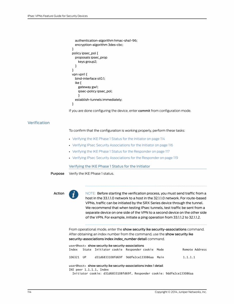
authentication-algorithm hmac-sha1-96;encryption-algorithm 3des-cbc;
}policy ipsec_pol {proposals ipsec_propkeys group2;
}}vpn vpn1 {bind-interface st0.1;ike {gateway gw1;ipsec-policy ipsec_pol;}
establish-tunnels immediately;}
If you are done configuring the device, enter commit from configuration mode.
Verification
To confirm that the configuration is working properly, perform these tasks:
• Verifying the IKE Phase 1 Status for the Initiator on page 114
• Verifying IPsec Security Associations for the Initiator on page 116
• Verifying the IKE Phase 1 Status for the Responder on page 117
• Verifying IPsec Security Associations for the Responder on page 119
Verifying the IKE Phase 1 Status for the Initiator
Purpose Verify the IKE Phase 1 status.
Action NOTE: Before starting the verification process, youmust send traffic from ahost in the 33.1.1.0 network to a host in the 32.1.1.0 network. For route-basedVPNs, traffic can be initiated by the SRX Series device through the tunnel.We recommend that when testing IPsec tunnels, test traffic be sent from aseparate device on one side of the VPN to a second device on the other sideof the VPN. For example, initiate a ping operation from 33.1.1.2 to 32.1.1.2.
From operational mode, enter the show security ike security-associations command.
After obtaining an index number from the command, use the show security ikesecurity-associations index index_number detail command.
user@host> show security ike security-associationsIndex State Initiator cookie Responder cookie Mode Remote Address
106321 UP d31d6833108fd69f 9ddfe2ce133086aa Main 1.1.1.1
user@host> show security ike security-associations index 1 detailIKE peer 1.1.1.1, Index Initiator cookie: d31d6833108fd69f, Responder cookie: 9ddfe2ce133086aa
Copyright © 2014, Juniper Networks, Inc.114
IPsec VPNs Feature Guide for Security Devices

Exchange type: Main, Authentication method: Pre-shared-keys Local: 1.0.0.1:4500, Remote: 1.1.1.1:4500 Lifetime: Expires in 28785 seconds Peer ike-id: [email protected] Xauth assigned IP: [email protected] Algorithms: Authentication : hmac-sha1-96 Encryption : 3des-cbc Pseudo random function: hmac-sha1 Traffic statistics: Input bytes : 0 Output bytes : 0 Input packets: 0 Output packets: 0 Flags: IKE SA is created IPSec security associations: 2 created, 0 deleted Phase 2 negotiations in progress: 0
Negotiation type: Quick mode, Role: Initiator, Message ID: 0 Local: 1.0.0.1:4500, Remote: 1.1.1.1:4500 Local identity: [email protected] Remote identity: [email protected] Flags: IKE SA is created
Meaning The show security ike security-associations command lists all active IKE Phase 1 SAs. If
no SAs are listed, there was a problem with Phase 1 establishment. Check the IKE policy
parameters and external interface settings in your configuration.
If SAs are listed, review the following information:
• Index—This value is unique for each IKE SA, which you can use in the show security ike
security-associations index detail command to get more information about the SA.
• Remote address—Verify that the remote IP address is correct and that port 4500 is
being used for peer-to-peer communication.
• Role initiator state
• Up—The Phase 1 SA has been established.
• Down—There was a problem establishing the Phase 1 SA.
• Both peers in the IPsec SA pair are using port 4500, which indicates that NAT-T is
implemented. (NAT-T uses port 4500 or another random high-numbered port.)
• Peer IKE ID—Verify the remote address is correct.
• Local identity and remote identity—Verify these are correct.
• Mode—Verify that the correct mode is being used.
Verify that the following are correct in your configuration:
• External interfaces (the interface must be the one that receives IKE packets)
• IKE policy parameters
• Preshared key information
• Phase 1 proposal parameters (must match on both peers)
115Copyright © 2014, Juniper Networks, Inc.
Chapter 14: Route-Based VPN

The show security ike security-associations command lists additional information about
security associations:
• Authentication and encryption algorithms used
• Phase 1 lifetime
• Traffic statistics (can be used to verify that traffic is flowing properly in both directions)
• Role information
NOTE: Troubleshooting is best performedon the peer using the responderrole.
• Initiator and responder information
• Number of IPsec SAs created
• Number of Phase 2 negotiations in progress
Verifying IPsec Security Associations for the Initiator
Purpose Verify the IPsec status.
Action From operational mode, enter the showsecurity ipsecsecurity-associations command.
After obtaining an index number from the command, use the show security ipsecsecurity-associations index index_number detail command.
user@host> show security ipsec security-associationsTotal active tunnels: 1 ID Algorithm SPI Life:sec/kb Mon vsys Port Gateway <131073 ESP:3des/sha1 ac23df79 2532/ unlim - root 4500 1.1.1.1 >131073 ESP:3des/sha1 cbc9281a 2532/ unlim - root 4500 1.1.1.1
user@host> show security ipsec security-associations detailVirtual-system: root Local Gateway: 1.0.0.1, Remote Gateway: 1.1.1.1 Local Identity: ipv4_subnet(any:0,[0..7]=0.0.0.0/0) Remote Identity: ipv4_subnet(any:0,[0..7]=0.0.0.0/0) Version: IKEv1 DF-bit: clear Direction: inbound, SPI: ac23df79, AUX-SPI: 0 , VPN Monitoring: - Hard lifetime: Expires in 3186 seconds Lifesize Remaining: Unlimited Soft lifetime: Expires in 2578 seconds Mode: Tunnel, Type: dynamic, State: installed Protocol: ESP, Authentication: hmac-sha1-96, Encryption: 3des-cbc Anti-replay service: counter-based enabled, Replay window size: 64
Direction: outbound, SPI: cbc9281a, AUX-SPI: 0 , VPN Monitoring: - Hard lifetime: Expires in 3186 seconds Lifesize Remaining: Unlimited Soft lifetime: Expires in 2578 seconds
Copyright © 2014, Juniper Networks, Inc.116
IPsec VPNs Feature Guide for Security Devices

Mode: Tunnel, Type: dynamic, State: installed Protocol: ESP, Authentication: hmac-sha1-96, Encryption: 3des-cbc Anti-replay service: counter-based enabled, Replay window size: 64
Meaning The output from the showsecurity ipsecsecurity-associationscommand lists the following
information:
• The remote gateway has a NAT address of 1.1.1.1.
• Both peers in the IPsec SA pair are using port 4500, which indicates that NAT-T is
implemented. (NAT-T uses port 4500 or another random high-numbered port.)
• The SPIs, lifetime (in seconds), and usage limits (or lifesize in KB) are shown for both
directions. The 2532/ unlim value indicates that the Phase 2 lifetime expires in 2532
seconds, and that no lifesize has been specified, which indicates that it is unlimited.
Phase 2 lifetime can differ from Phase 1 lifetime, as Phase 2 is not dependent on Phase
1 after the VPN is up.
• VPN monitoring is not enabled for this SA, as indicated by a hyphen in the Mon column.
If VPN monitoring is enabled, U indicates that monitoring is up, and D indicates that
monitoring is down.
• The virtual system (vsys) is the root system, and it always lists 0.
Verifying the IKE Phase 1 Status for the Responder
Purpose Verify the IKE Phase 1 status.
Action From operational mode, enter the show security ike security-associations command.
After obtaining an index number from the command, use the show security ikesecurity-associations index index_number detail command.
user@host> show security ike security-associationsIndex State Initiator cookie Responder cookie Mode Remote Address
5802591 UP d31d6833108fd69f 9ddfe2ce133086aa Main 1.0.0.1
user@host> show security ike security-associations index 1 detailIKE peer 1.0.0.1, Index 5802591, Role: Responder, State: UP Initiator cookie: d31d6833108fd69f, Responder cookie: 9ddfe2ce133086aa Exchange type: Main, Authentication method: Pre-shared-keys Local: 71.1.1.1:4500, Remote: 1.0.0.1:4500 Lifetime: Expires in 25704 seconds Peer ike-id: [email protected] Xauth assigned IP: 0.0.0.0 Algorithms: Authentication : hmac-sha1-96 Encryption : 3des-cbc Pseudo random function: hmac-sha1 Traffic statistics: Input bytes : 0 Output bytes : 0 Input packets: 0 Output packets: 0 Flags: IKE SA is created IPSec security associations: 8 created, 2 deleted
117Copyright © 2014, Juniper Networks, Inc.
Chapter 14: Route-Based VPN

Phase 2 negotiations in progress: 0
Negotiation type: Quick mode, Role: Responder, Message ID: 0 Local: 71.1.1.1:4500, Remote: 1.0.0.1:4500 Local identity: [email protected] Remote identity: [email protected] Flags: IKE SA is created
Meaning The show security ike security-associations command lists all active IKE Phase 1 SAs. If
no SAs are listed, there was a problem with Phase 1 establishment. Check the IKE policy
parameters and external interface settings in your configuration.
If SAs are listed, review the following information:
• Index—This value is unique for each IKE SA, which you can use in the show security ike
security-associations index detail command to get more information about the SA.
• Remote address—Verify that the remote IP address is correct and that port 4500 is
being used for peer-to-peer communication.
• Role responder state
• Up—The Phase 1 SA has been established.
• Down—There was a problem establishing the Phase 1 SA.
• Peer IKE ID—Verify the address is correct.
• Local identity and remote identity—Verify these addresses are correct.
• Mode—Verify that the correct mode is being used.
Verify that the following are correct in your configuration:
• External interfaces (the interface must be the one that receives IKE packets)
• IKE policy parameters
• Preshared key information
• Phase 1 proposal parameters (must match on both peers)
The show security ike security-associations command lists additional information about
security associations:
• Authentication and encryption algorithms used
• Phase 1 lifetime
• Traffic statistics (can be used to verify that traffic is flowing properly in both directions)
• Role information
NOTE: Troubleshooting is best performedon the peer using the responderrole.
Copyright © 2014, Juniper Networks, Inc.118
IPsec VPNs Feature Guide for Security Devices

• Initiator and responder information
• Number of IPsec SAs created
• Number of Phase 2 negotiations in progress
Verifying IPsec Security Associations for the Responder
Purpose Verify the IPsec status.
Action From operational mode, enter the showsecurity ipsecsecurity-associations command.
After obtaining an index number from the command, use the show security ipsecsecurity-associations index index_number detail command.
user@host> show security ipsec security-associationsTotal active tunnels: 1 ID Algorithm SPI Life:sec/kb Mon vsys Port Gateway <131073 ESP:3des/sha1 a5224cd9 3571/ unlim - root 4500 1.0.0.1 >131073 ESP:3des/sha1 82a86a07 3571/ unlim - root 4500 1.0.0.1
user@host> show security ipsec security-associations detailVirtual-system: root Local Gateway: 71.1.1.1, Remote Gateway: 1.0.0.1 Local Identity: ipv4_subnet(any:0,[0..7]=0.0.0.0/0) Remote Identity: ipv4_subnet(any:0,[0..7]=0.0.0.0/0) Version: IKEv1 DF-bit: clear Direction: inbound, SPI: a5224cd9, AUX-SPI: 0 , VPN Monitoring: - Hard lifetime: Expires in 3523 seconds Lifesize Remaining: Unlimited Soft lifetime: Expires in 2923 seconds Mode: Tunnel, Type: dynamic, State: installed Protocol: ESP, Authentication: hmac-sha1-96, Encryption: 3des-cbc Anti-replay service: counter-based enabled, Replay window size: 64
Direction: outbound, SPI: 82a86a07, AUX-SPI: 0 , VPN Monitoring: - Hard lifetime: Expires in 3523 seconds Lifesize Remaining: Unlimited Soft lifetime: Expires in 2923 seconds Mode: Tunnel, Type: dynamic, State: installed Protocol: ESP, Authentication: hmac-sha1-96, Encryption: 3des-cbc Anti-replay service: counter-based enabled, Replay window size: 64
Meaning The output from the showsecurity ipsecsecurity-associationscommand lists the following
information:
• The remote gateway has an ip address of 1.0.0.1.
• Both peers in the IPsec SA pair are using port 4500, which indicates that NAT-T is
implemented. (NAT-T uses port 4500 or another random high-numbered port.)
• The SPIs, lifetime (in seconds), and usage limits (or lifesize in KB) are shown for both
directions. The 3571/ unlim value indicates that the Phase 2 lifetime expires in 3571
seconds, and that no lifesize has been specified, which indicates that it is unlimited.
119Copyright © 2014, Juniper Networks, Inc.
Chapter 14: Route-Based VPN

Phase 2 lifetime can differ from Phase 1 lifetime, as Phase 2 is not dependent on Phase
1 after the VPN is up.
• VPN monitoring is not enabled for this SA, as indicated by a hyphen in the Mon column.
If VPN monitoring is enabled, U indicates that monitoring is up, and D indicates that
monitoring is down.
• The virtual system (vsys) is the root system, and it always lists 0.
The output from the show security ipsec security-associations index index_iddetail
command lists the following information:
• The local identity and remote identity make up the proxy ID for the SA.
A proxy ID mismatch is one of the most common causes for a Phase 2 failure. If no
IPsec SA is listed, confirm that Phase 2 proposals, including the proxy ID settings, are
correct for both peers. For route-based VPNs, the default proxy ID is local=0.0.0.0/0,
remote=0.0.0.0/0, and service=any. Issues can occur with multiple route-based VPNs
from the same peer IP. In this case, a unique proxy ID for each IPsec SA must be
specified. For some third-party vendors, the proxy ID must be manually entered to
match.
• Another common reason for Phase 2 failure is not specifying the ST interface binding.
If IPsec cannot complete, check the kmd log or set traceoptions.
RelatedDocumentation
VPN Overview on page 3•
• Understanding NAT-T on page 49
• Example: Configuring a Policy-Based VPN with Both an Initiator and a Responder
Behind a NAT Device on page 142
• IPsec VPNs Feature Guide for Security Devices
Example: Configuring an st0 Interface in a Virtual Router
Supported Platforms J Series, LN Series, SRX Series
This example shows how to configure an st0 interface in a virtual router.
• Requirements on page 120
• Overview on page 120
• Configuration on page 121
• Verification on page 124
Requirements
Before you begin, configure the interfaces and assign the interfaces to security zones.
See Security Zones and Interfaces Overview.
Overview
In this example, you perform the following operations:
Copyright © 2014, Juniper Networks, Inc.120
IPsec VPNs Feature Guide for Security Devices

• Configure the interfaces.
• Configure IKE Phase 1 proposals.
• Configure IKE policies, and reference the proposals.
• Configure an IKE gateway, and reference the policy.
• Configure Phase 2 proposals.
• Configure policies, and reference the proposals.
• Configure AutoKey IKE, and reference the policy and gateway.
• Configure the security policy.
• Configure the routing instance.
• Configure the VPN bind to tunnel interface.
• Configure the routing options.
Configuration
CLI QuickConfiguration
To quickly configure this example, copy the following commands, paste them into a text
file, remove any line breaks, change any details necessary to match your network
configuration, and then copy and paste the commands into the CLI at the [edit]hierarchy
level.
set interfaces ge-0/0/0 unit 0 family inet address 1.1.1.2/30set interfaces ge-0/0/1 unit 0 family inet address 2.2.2.2/30set interfaces st0 unit 0 family inet address 3.3.3.2/30set security ike proposal first_ikeprop authentication-method pre-shared-keysset security ike proposal first_ikeprop dh-group group2set security ike proposal first_ikeprop authentication-algorithmmd5set security ike proposal first_ikeprop encryption-algorithm 3des-cbcset security ike policy first_ikepol modemainset security ike policy first_ikepol proposals first_ikepropset security ike policy first_ikepol pre-shared-key ascii-text"$9$xFU-b2ZUH5Qn4aQn/CB17-V"
set security ike gateway first ike-policy first_ikepolset security ike gateway first address 4.4.4.2set security ike gateway first external-interface ge-0/0/0.0set security ipsec proposal first_ipsecprop protocol espset security ipsec proposal first_ipsecprop authentication-algorithm hmac-md5-96set security ipsec proposal first_ipsecprop encryption-algorithm 3des-cbcset security ipsec policy first_ipsecpol perfect-forward-secrecy keys group1set security ipsec policy first_ipsecpol proposals first_ipsecpropset security ipsec vpn first_vpn bind-interface st0.0set security ipsec vpn first_vpn ike gateway firstset security ipsec vpn first_vpn ike ipsec-policy first_ipsecpolset security ipsec vpn first_vpn establish-tunnels immediatelyset security policies default-policy permit-allset routing-instances VR1 instance-type virtual-routerset routing-instances VR1 interface ge-0/0/1.0set routing-instances VR1 interface st0.0set routing-instances VR1 routing-options static route 6.6.6.0/24 next-hop st0.0
121Copyright © 2014, Juniper Networks, Inc.
Chapter 14: Route-Based VPN

Step-by-StepProcedure
The following example requires you to navigate various levels in the configuration
hierarchy. For instructions on how to do that, see Using the CLI Editor in Configuration
Mode.
To configure an st0 in a VR:
1. Configure the interfaces.
[edit]user@host# set interfaces ge-0/0/0 unit 0 family inet address 1.1.1.2/30user@host# set interfaces ge-0/0/1 unit 0 family inet address 2.2.2.2/30user@host# set interfaces st0 unit 0 family inet address 3.3.3.2/30
2. Configure Phase 1 of the IPsec tunnel.
[edit security ike]user@host# set proposal first_ikeprop authentication-method pre-shared-keysuser@host# set proposal first_ikeprop dh-group group2user@host# set proposal first_ikeprop authentication-algorithmmd5user@host# set proposal first_ikeprop encryption-algorithm 3des-cbc
3. Configure the IKE policies, and reference the proposals.
[edit security ike]user@host# set policy first_ikepol modemainuser@host# set policy first_ikepol proposals first_ikepropuser@host# set policy first_ikepol pre-shared-key ascii-text"$9$xFU-b2ZUH5Qn4aQn/CB17-V"
4. Configure the IKE gateway, and reference the policy.
[edit security ike]user@host# set gateway first ike-policy first_ikepoluser@host# set gateway first address 4.4.4.2user@host# set gateway first external-interface ge-0/0/0.0
5. Configure Phase 2 of the IPsec tunnel.
[edit security ipsec]user@host# set proposal first_ipsecprop protocol espuser@host# set proposal first_ipsecprop authentication-algorithm hmac-md5-96user@host# set proposal first_ipsecprop encryption-algorithm 3des-cbc
6. Configure the policies, and reference the proposals.
[edit security ipsec]user@host# set policy first_ipsecpol perfect-forward-secrecy keys group1user@host# set policy first_ipsecpol proposals first_ipsecprop
7. Configure AutoKey IKE, and reference the policy and gateway.
[edit security ipsec]user@host# set vpn first_vpn ike gateway firstuser@host# set vpn first_vpn ike ipsec-policy first_ipsecpoluser@host# set vpn first_vpn establish-tunnels immediately
8. Configure the VPN bind to tunnel interface.
[edit security ipsec]user@host# set vpn first_vpn bind-interface st0.0
Copyright © 2014, Juniper Networks, Inc.122
IPsec VPNs Feature Guide for Security Devices

9. Configure the security policy.
[edit security policies]user@host# set default-policy permit-all
10. Configure the st0 in the routing instance.
[edit routing-instances]user@host# set VR1 instance-type virtual-routeruser@host# set VR1 interface ge-0/0/1.0user@host# set VR1 interface st0.0
11. Configure the routing options.
[edit routing-instances VR1 routing-options]user@host# set static route 6.6.6.0/24 next-hop st0.0
Results From configuration mode, confirm your configuration by entering the show security and
show routing-instances commands. If the output does not display the intended
configuration, repeat the configuration instructions in this example to correct it.
user@host# show securityike {proposal first_ikeprop {authentication-method pre-shared-keys;dh-group group2;authentication-algorithmmd5;encryption-algorithm 3des-cbc;
}policy first_ikepol {modemain;proposals first_ikeprop;pre-shared-key ascii-text "$9$xFU-b2ZUH5Qn4aQn/CB17-V"; ## SECRET-DATA
}gateway first {ike-policy first_ikepol;address 4.4.4.2;external-interface ge-0/0/0.0;
}}ipsec {proposal first_ipsecprop {protocol esp;authentication-algorithm hmac-md5-96;encryption-algorithm 3des-cbc;
}policy first_ipsecpol {perfect-forward-secrecy {keys group1;
}proposals first_ipsecprop;
}vpn first_vpn {bind-interface st0.0;ike {gateway first;ipsec-policy first_ipsecpol;
123Copyright © 2014, Juniper Networks, Inc.
Chapter 14: Route-Based VPN

}establish-tunnels immediately;
}}
policies {default-policy {permit-all;
}}user@host# show routing-instances
VR1 {instance-type virtual-router;interface ge-0/0/1.0;interface st0.0;routing-options {static {route 6.6.6.0/24 next-hop st0.0;
}}
}
If you are done configuring the device, enter commit from configuration mode.
Verification
To confirm that the configuration is working properly, perform this task:
• Verifying an st0 interface in the Virtual Router on page 124
Verifying an st0 interface in the Virtual Router
Purpose Verify the st0 interface in the virtual router.
Action From operational mode, enter the show interfaces st0.0 detail command. The number
listed for routing table corresponds to the order that the routing tables in the show route
all command.
RelatedDocumentation
• IPsec VPNs Feature Guide for Security Devices
Copyright © 2014, Juniper Networks, Inc.124
IPsec VPNs Feature Guide for Security Devices

CHAPTER 15
Policy-Based VPN
• Example: Configuring a Policy-Based VPN on page 125
• Example: Configuring a Policy-Based VPN with Both an Initiator and a Responder
Behind a NAT Device on page 142
Example: Configuring a Policy-Based VPN
Supported Platforms J Series, LN Series, SRX Series
This example shows how to configure a policy-based IPsec VPN to allow data to be
securely transferred between a branch office and the corporate office.
• Requirements on page 125
• Overview on page 125
• Configuration on page 129
• Verification on page 138
Requirements
This example uses the following hardware:
• SRX240 device
• SSG140 device
Before you begin, read “VPN Overview” on page 3.
Overview
In this example, you configure a policy-based VPN for a branch office in Chicago, Illinois,
because you do not need to conserve tunnel resources or configure many security policies
to filter traffic through the tunnel. Users in the Chicago office will use the VPN to connect
to their corporate headquarters in Sunnyvale, California.
Figure 15 on page 126 shows an example of a policy-based VPN topology. In this topology,
the SRX Series device is located in Sunnyvale, and an SSG Series device (or it can be
another third-party device) is located in Chicago.
125Copyright © 2014, Juniper Networks, Inc.

Figure 15: Policy-Based VPN Topology
Trust zone
192.168.168.10/24
e0/02.2.2.2/30
e0/6192.168.168.1/24
Untrustzone
Internet
Trust zone
SSG Series deviceChicago
ge-0/0/0.010.10.10.1/24
SRX Series device
Sunnyvale
10.10.10.10/24
ge-0/0/3.01.1.1.2/30
IKE IPsec tunnel negotiation occurs in two phases. In Phase 1, participants establish a
secure channel in which to negotiate the IPsec security association (SA). In Phase 2,
participants negotiate the IPsec SA for authenticating traffic that will flow through the
tunnel. Just as there are two phases to tunnel negotiation, there are two phases to tunnel
configuration.
Copyright © 2014, Juniper Networks, Inc.126
IPsec VPNs Feature Guide for Security Devices
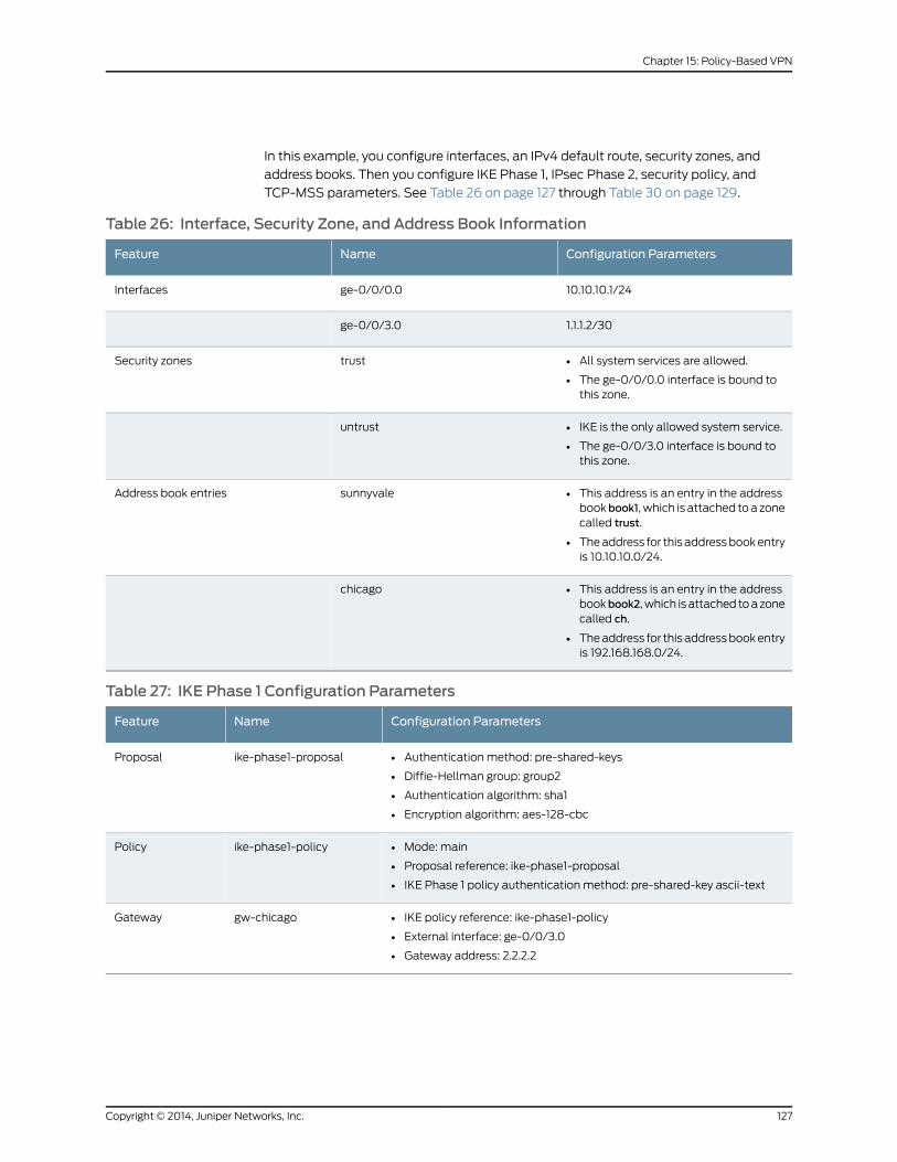
In this example, you configure interfaces, an IPv4 default route, security zones, and
address books. Then you configure IKE Phase 1, IPsec Phase 2, security policy, and
TCP-MSS parameters. See Table 26 on page 127 through Table 30 on page 129.
Table 26: Interface, Security Zone, and Address Book Information
Configuration ParametersNameFeature
10.10.10.1/24ge-0/0/0.0Interfaces
1.1.1.2/30ge-0/0/3.0
• All system services are allowed.
• The ge-0/0/0.0 interface is bound tothis zone.
trustSecurity zones
• IKE is the only allowed system service.
• The ge-0/0/3.0 interface is bound tothis zone.
untrust
• This address is an entry in the addressbookbook1, which is attached to a zonecalled trust.
• The address for this address book entryis 10.10.10.0/24.
sunnyvaleAddress book entries
• This address is an entry in the addressbookbook2, which is attached to a zonecalled ch.
• The address for this address book entryis 192.168.168.0/24.
chicago
Table 27: IKE Phase 1 Configuration Parameters
Configuration ParametersNameFeature
• Authentication method: pre-shared-keys
• Diffie-Hellman group: group2
• Authentication algorithm: sha1
• Encryption algorithm: aes-128-cbc
ike-phase1-proposalProposal
• Mode: main
• Proposal reference: ike-phase1-proposal
• IKE Phase 1 policy authentication method: pre-shared-key ascii-text
ike-phase1-policyPolicy
• IKE policy reference: ike-phase1-policy
• External interface: ge-0/0/3.0
• Gateway address: 2.2.2.2
gw-chicagoGateway
127Copyright © 2014, Juniper Networks, Inc.
Chapter 15: Policy-Based VPN

Table 28: IPsec Phase 2 Configuration Parameters
Configuration ParametersNameFeature
• Protocol: esp
• Authentication algorithm: hmac-sha1-96
• Encryption algorithm: aes-128-cbc
ipsec-phase2-proposalProposal
• Proposal reference: ipsec-phase2-proposal
• PFS: Diffie-Hellman group2
ipsec-phase2-policyPolicy
• IKE gateway reference: gw-chicago
• IPsec policy reference: ipsec-phase2-policy
ike-vpn-chicagoVPN
Table 29: Security Policy Configuration Parameters
Configuration ParametersNamePurpose
• Match criteria:
• source-address sunnyvale
• destination-address chicago
• application any
• Permit action: tunnel ipsec-vpn ike-vpn-chicago
• Permit action: tunnel pair-policy vpn-untr-tr
vpn-tr-untrThis security policy permits traffic from the trust zone tothe untrust zone.
• Match criteria:
• source-address chicago
• destination-address sunnyvale
• application any
• Permit action: tunnel ipsec-vpn ike-vpn-chicago
• Permit action: tunnel pair-policy vpn-tr-untr
vpn-untr-trThis security policy permits traffic from the untrust zoneto the trust zone.
• Match criteria:
• source-address any
• source-destination any
• application any
• Action: permit
permit-anyThis security policy permits all traffic from the trust zoneto the untrust zone.
NOTE: You must put the vpn-tr-untr policy before thepermit-any security policy. Junos OS performs a securitypolicy lookup starting at the top of the list. If thepermit-any policy comes before the vpn-tr-untr policy,all traffic from the trust zone will match the permit-anypolicy and be permitted. Thus, no traffic will ever matchthe vpn-tr-untr policy.
Copyright © 2014, Juniper Networks, Inc.128
IPsec VPNs Feature Guide for Security Devices

Table 30: TCP-MSS Configuration Parameters
ConfigurationParametersPurpose
MSS value: 1350TCP-MSS is negotiated as part of the TCP three-way handshake and limits the maximum size of a TCPsegment to better fit the maximum transmission unit (MTU) limits on a network. This is especiallyimportant for VPN traffic, as the IPsec encapsulation overhead, along with the IP and frame overhead,can cause the resulting Encapsulating Security Payload (ESP) packet to exceed the MTU of the physicalinterface, thus causing fragmentation. Fragmentation results in increased use of bandwidth and deviceresources.
NOTE: We recommend a value of 1350 as the starting point for most Ethernet-based networks withan MTU of 1500 or greater. You might need to experiment with different TCP-MSS values to obtainoptimal performance. For example, you might need to change the value if any device in the path has alower MTU, or if there is any additional overhead such as PPP or Frame Relay.
Configuration
Configuring Basic Network, Security Zone, and Address Book Information
CLI QuickConfiguration
To quickly configure this section of the example, copy the following commands, paste
them into a text file, remove any line breaks, change any details necessary to match your
network configuration, and then copy and paste the commands into the CLI at the [edit]
hierarchy level.
set interfaces ge-0/0/0 unit 0 family inet address 10.10.10.1/24set interfaces ge-0/0/3 unit 0 family inet address 1.1.1.2/30set routing-options static route 0.0.0.0/0 next-hop 1.1.1.1set security zones security-zone untrust interfaces ge-0/0/3.0set security zones security-zone untrust host-inbound-traffic system-services ikeset security zones security-zone trust interfaces ge-0/0/0.0set security zones security-zone trust host-inbound-traffic system-services allset security address-book book1 address sunnyvale 10.10.10.0/24set security address-book book1 attach zone trustset security address-book book2 address chicago 192.168.168.0/24set security address-book book2 attach zone untrust
Step-by-StepProcedure
The following example requires you to navigate various levels in the configuration
hierarchy. For instructions on how to do that, see Using the CLI Editor in Configuration
Mode.
To configure basic network, security zone, and address book information:
1. Configure Ethernet interface information.
[edit]user@host# set interfaces ge-0/0/0 unit 0 family inet address 10.10.10.1/24user@host# set interfaces ge-0/0/3 unit 0 family inet address 1.1.1.2/30
2. Configure static route information.
[edit]user@host# set routing-options static route 0.0.0.0/0 next-hop 1.1.1.1
3. Configure the untrust security zone.
129Copyright © 2014, Juniper Networks, Inc.
Chapter 15: Policy-Based VPN

[edit ]user@host# edit security zones security-zone untrust
4. Assign an interface to the security zone.
[edit security zones security-zone untrust]user@host# set interfaces ge-0/0/3.0
5. Specify allowed system services for the security zone.
[edit security zones security-zone untrust]user@host# set host-inbound-traffic system-services ike
6. Configure the trust security zone.
[edit]user@host# edit security zones security-zone trust
7. Assign an interface to the security zone.
[edit security zones security-zone trust]user@host# set interfaces ge-0/0/0.0
8. Specify allowed system services for the security zone.
[edit security zones security-zone trust]user@host# set host-inbound-traffic system-services all
9. Create an address book and attach it to a zone.
[edit security address-book book1]user@host# set address sunnyvale 10.10.10.0/24user@host# set attach zone trust
10. Create another address book and attach it to a zone.
[edit security address-book book2]user@host# set address chicago 192.168.168.0/24user@host# set attach zone untrust
Results From configuration mode, confirm your configuration by entering the show interfaces,
show routing-options, show security zones, and show security address-book commands.
If the output does not display the intended configuration, repeat the configuration
instructions in this example to correct it.
[edit]user@host# show interfacesge-0/0/0 {unit 0 {family inet {address 10.10.10.1/24;
}}
}ge-0/0/3 {unit 0 {family inet {address 1.1.1.2/30
}}
Copyright © 2014, Juniper Networks, Inc.130
IPsec VPNs Feature Guide for Security Devices
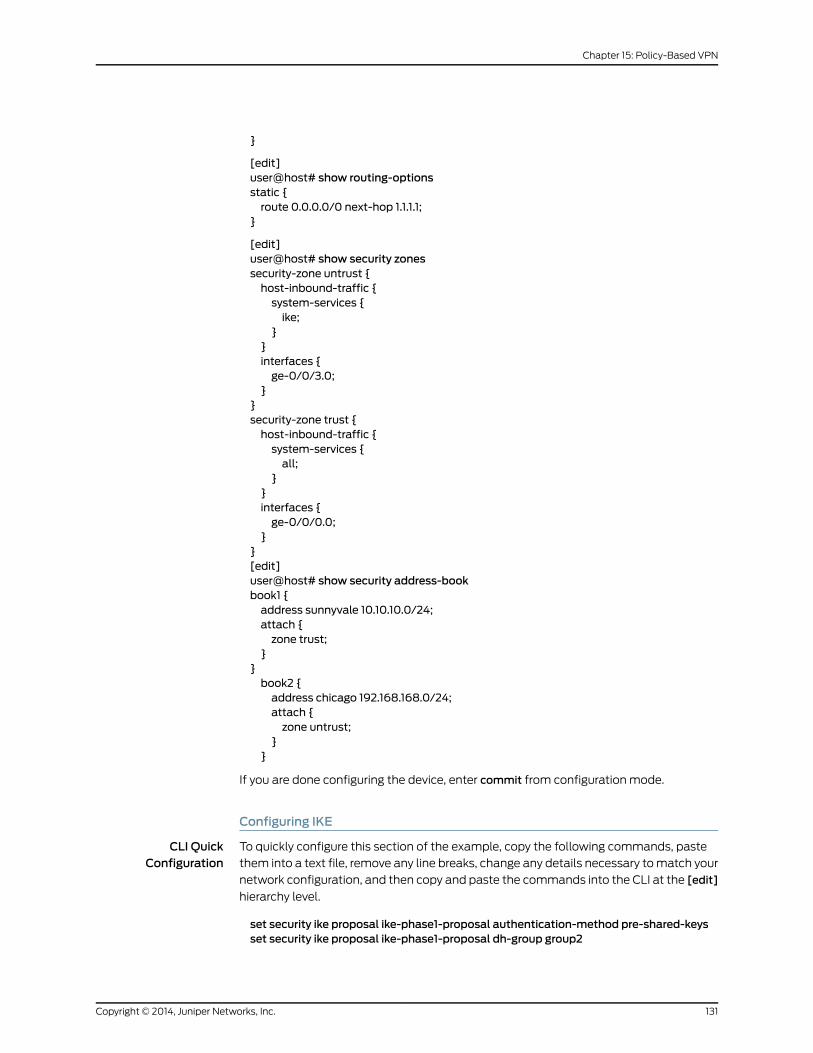
}
[edit]user@host# show routing-optionsstatic {route 0.0.0.0/0 next-hop 1.1.1.1;
}
[edit]user@host# show security zonessecurity-zone untrust {host-inbound-traffic {system-services {ike;
}}interfaces {ge-0/0/3.0;
}}security-zone trust {host-inbound-traffic {system-services {all;
}}interfaces {ge-0/0/0.0;
}}[edit]user@host# show security address-bookbook1 {address sunnyvale 10.10.10.0/24;attach {zone trust;
}}book2 {address chicago 192.168.168.0/24;attach {zone untrust;
}}
If you are done configuring the device, enter commit from configuration mode.
Configuring IKE
CLI QuickConfiguration
To quickly configure this section of the example, copy the following commands, paste
them into a text file, remove any line breaks, change any details necessary to match your
network configuration, and then copy and paste the commands into the CLI at the [edit]
hierarchy level.
set security ike proposal ike-phase1-proposal authentication-method pre-shared-keysset security ike proposal ike-phase1-proposal dh-group group2
131Copyright © 2014, Juniper Networks, Inc.
Chapter 15: Policy-Based VPN

set security ike proposal ike-phase1-proposal authentication-algorithm sha1set security ike proposal ike-phase1-proposal encryption-algorithm aes-128-cbcset security ike policy ike-phase1-policymodemainset security ike policy ike-phase1-policy proposals ike-phase1-proposalset security ike policy ike-phase1-policy pre-shared-key ascii-text 395psksecr3tset security ike gateway gw-chicago external-interface ge-0/0/3.0set security ike gateway gw-chicago ike-policy ike-phase1-policyset security ike gateway gw-chicago address 2.2.2.2
Step-by-StepProcedure
The following example requires you to navigate various levels in the configuration
hierarchy. For instructions on how to do that, see Using the CLI Editor in Configuration
Mode
To configure IKE:
1. Create the IKE Phase 1 proposal.
[edit security ike]user@host# set proposal ike-phase1-proposal
2. Define the IKE proposal authentication method.
[edit security ike proposal ike-phase1-proposal]user@host# set authentication-method pre-shared-keys
3. Define the IKE proposal Diffie-Hellman group.
[edit security ike proposal ike-phase1-proposal]user@host# set dh-group group2
4. Define the IKE proposal authentication algorithm.
[edit security ike proposal ike-phase1-proposal]user@host# set authentication-algorithm sha1
5. Define the IKE proposal encryption algorithm.
[edit security ike proposal ike-phase1-proposal]user@host# set encryption-algorithm aes-128-cbc
6. Create an IKE Phase 1 policy.
[edit security ike]user@host# set policy ike-phase1-policy
7. Set the IKE Phase 1 policy mode.
[edit security ike policy ike-phase1-policy]user@host# setmodemain
8. Specify a reference to the IKE proposal.
[edit security ike policy ike-phase1-policy]user@host# set proposals ike-phase1-proposal
9. Define the IKE Phase 1 policy authentication method.
[edit security ike policy ike-phase1-policy]user@host# set pre-shared-key ascii-text 395psksecr3t
10. Create an IKE Phase 1 gateway and define its external interface.
[edit security ike]
Copyright © 2014, Juniper Networks, Inc.132
IPsec VPNs Feature Guide for Security Devices

user@host# set gateway gw-chicago external-interface ge-0/0/3.0
11. Define the IKE Phase 1 policy reference.
[edit security ike gateway gw-chicago]user@host# set ike-policy ike-phase1-policy
12. Create an IKE Phase 1 gateway and define its external interface.
[edit security ike gateway gw-chicago]user@host# set gateway gw-chicago external-interface ge-0/0/3.0
13. Define the IKE Phase 1 policy reference.
[edit security ike gateway gw-chicago]user@host# set ike-policy ike-phase1-policy
Results From configuration mode, confirm your configuration by entering the show security ike
command. If the output does not display the intended configuration, repeat the
configuration instructions in this example to correct it.
[edit]user@host# show security ikeproposal ike-phase1-proposal {authentication-method pre-shared-keys;dh-group group2;authentication-algorithm sha1;encryption-algorithm aes-128-cbc;
}policy ike-phase1-policy {modemain;proposals ike-phase1-proposal;pre-shared-key ascii-text "$9$9VMTp1RvWLdwYKMJDkmF3ylKM87Vb2oZjws5F"; ##SECRET-DATA
}gateway gw-chicago {ike-policy ike-phase1-policy;address 2.2.2.2;external-interface ge-0/0/3.0;
}
If you are done configuring the device, enter commit from configuration mode.
Configuring IPsec
CLI QuickConfiguration
To quickly configure this section of the example, copy the following commands, paste
them into a text file, remove any line breaks, change any details necessary to match your
network configuration, and then copy and paste the commands into the CLI at the [edit]
hierarchy level.
set security ipsec proposal ipsec-phase2-proposal protocol espsetsecurity ipsecproposal ipsec-phase2-proposalauthentication-algorithmhmac-sha1-96set security ipsec proposal ipsec-phase2-proposal encryption-algorithm aes-128-cbcset security ipsec policy ipsec-phase2-policy proposals ipsec-phase2-proposalset security ipsec policy ipsec-phase2-policy perfect-forward-secrecy keys group2set security ipsec vpn ike-vpn-chicago ike gateway gw-chicagoset security ipsec vpn ike-vpn-chicago ike ipsec-policy ipsec-phase2-policy
133Copyright © 2014, Juniper Networks, Inc.
Chapter 15: Policy-Based VPN

Step-by-StepProcedure
The following example requires you to navigate various levels in the configuration
hierarchy. For instructions on how to do that, see Using the CLI Editor in Configuration
Mode.
To configure IPsec:
1. Create an IPsec Phase 2 proposal.
[edit]user@host# set security ipsec proposal ipsec-phase2-proposal
2. Specify the IPsec Phase 2 proposal protocol.
[edit security ipsec proposal ipsec-phase2-proposal]user@host# set protocol esp
3. Specify the IPsec Phase 2 proposal authentication algorithm.
[edit security ipsec proposal ipsec-phase2-proposal]user@host# set authentication-algorithm hmac-sha1-96
4. Specify the IPsec Phase 2 proposal encryption algorithm.
[edit security ipsec proposal ipsec-phase2-proposal]user@host# set encryption-algorithm aes-128-cbc
5. Create the IPsec Phase 2 policy.
[edit security ipsec]user@host# set policy ipsec-phase2-policy
6. Specify the IPsec Phase 2 proposal reference.
[edit security ipsec policy ipsec-phase2-policy]user@host# set proposals ipsec-phase2-proposal
7. Specify IPsec Phase 2 PFS to use Diffie-Hellman group 2.
[edit security ipsec policy ipsec-phase2-policy]user@host# set perfect-forward-secrecy keys group2
8. Specify the IKE gateway.
[edit security ipsec]user@host# set vpn ike-vpn-chicago ike gateway gw-chicago
9. Specify the IPsec Phase 2 policy.
[edit security ipsec]user@host# set vpn ike-vpn-chicago ike ipsec-policy ipsec-phase2-policy
Results From configuration mode, confirm your configuration by entering the show security ipsec
command. If the output does not display the intended configuration, repeat the
configuration instructions in this example to correct it.
[edit]user@host# show security ipsecproposal ipsec-phase2-proposal {protocol esp;authentication-algorithm hmac-sha1-96;encryption-algorithm aes-128-cbc;
Copyright © 2014, Juniper Networks, Inc.134
IPsec VPNs Feature Guide for Security Devices
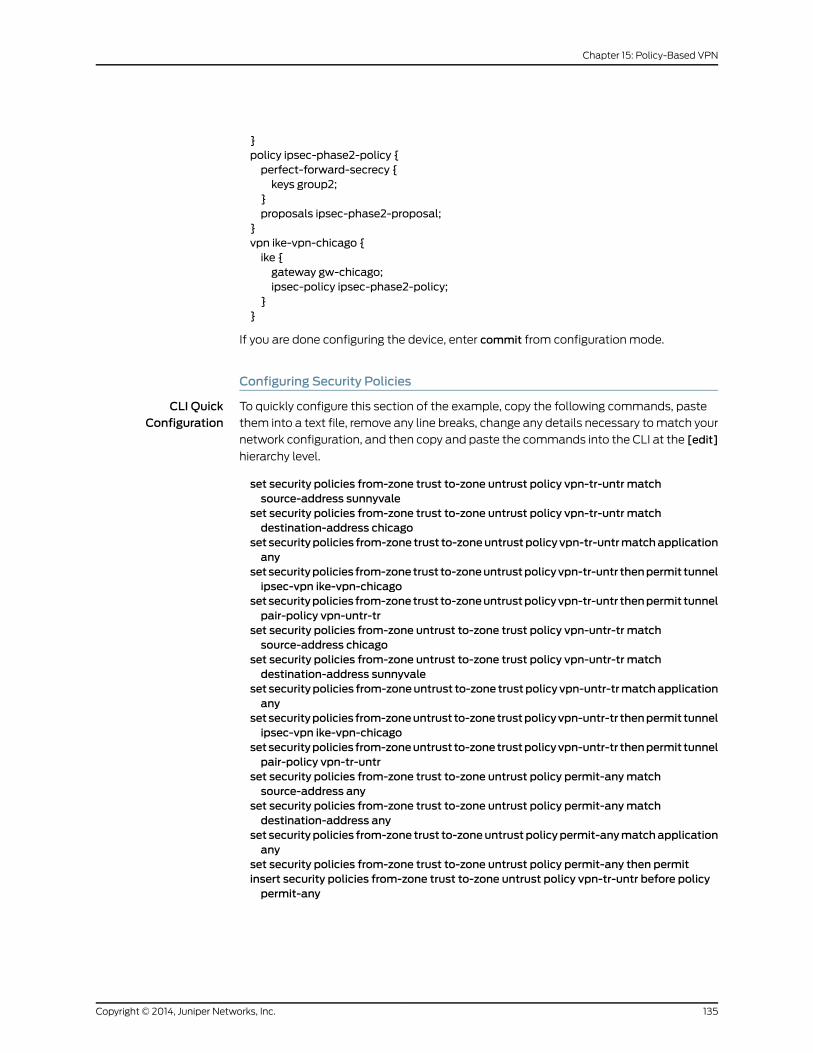
}policy ipsec-phase2-policy {perfect-forward-secrecy {keys group2;
}proposals ipsec-phase2-proposal;
}vpn ike-vpn-chicago {ike {gateway gw-chicago;ipsec-policy ipsec-phase2-policy;
}}
If you are done configuring the device, enter commit from configuration mode.
Configuring Security Policies
CLI QuickConfiguration
To quickly configure this section of the example, copy the following commands, paste
them into a text file, remove any line breaks, change any details necessary to match your
network configuration, and then copy and paste the commands into the CLI at the [edit]
hierarchy level.
set security policies from-zone trust to-zone untrust policy vpn-tr-untr matchsource-address sunnyvale
set security policies from-zone trust to-zone untrust policy vpn-tr-untr matchdestination-address chicago
set securitypolicies from-zone trust to-zoneuntrustpolicy vpn-tr-untrmatchapplicationany
setsecuritypolicies from-zonetrust to-zoneuntrustpolicyvpn-tr-untr thenpermit tunnelipsec-vpn ike-vpn-chicago
setsecuritypolicies from-zonetrust to-zoneuntrustpolicyvpn-tr-untr thenpermit tunnelpair-policy vpn-untr-tr
set security policies from-zone untrust to-zone trust policy vpn-untr-tr matchsource-address chicago
set security policies from-zone untrust to-zone trust policy vpn-untr-tr matchdestination-address sunnyvale
set securitypolicies from-zoneuntrust to-zone trustpolicy vpn-untr-trmatchapplicationany
setsecuritypolicies from-zoneuntrust to-zonetrustpolicyvpn-untr-tr thenpermit tunnelipsec-vpn ike-vpn-chicago
setsecuritypolicies from-zoneuntrust to-zonetrustpolicyvpn-untr-tr thenpermit tunnelpair-policy vpn-tr-untr
set security policies from-zone trust to-zone untrust policy permit-anymatchsource-address any
set security policies from-zone trust to-zone untrust policy permit-anymatchdestination-address any
set securitypolicies from-zone trust to-zoneuntrustpolicypermit-anymatchapplicationany
set security policies from-zone trust to-zone untrust policy permit-any then permitinsert security policies from-zone trust to-zone untrust policy vpn-tr-untr before policypermit-any
135Copyright © 2014, Juniper Networks, Inc.
Chapter 15: Policy-Based VPN

Step-by-StepProcedure
The following example requires you to navigate various levels in the configuration
hierarchy. For instructions on how to do that, see Using the CLI Editor in Configuration
Mode.
To configure security policies:
1. Create the security policy to permit traffic from the trust zone to the untrust zone.
[edit security policies from-zone trust to-zone untrust]user@host# set policy vpn-tr-untr match source-address sunnyvaleuser@host# set policy vpn-tr-untr match destination-address chicagouser@host# set policy vpn-tr-untr match application anyuser@host# set policy vpn-tr-untr then permit tunnel ipsec-vpn ike-vpn-chicagouser@host# set policy vpn-tr-untr then permit tunnel pair-policy vpn-untr-tr
2. Create the security policy to permit traffic from the untrust zone to the trust zone.
[edit security policies from-zone untrust to-zone trust]user@host# set policy vpn-untr-tr match source-address sunnyvaleuser@host# set policy vpn-untr-tr match destination-address chicagouser@host# set policy vpn-untr-tr match application anyuser@host# set policy vpn-untr-tr then permit tunnel ipsec-vpn ike-vpn-chicagouser@host# set policy vpn-untr-tr then permit tunnel pair-policy vpn-tr-untr
3. Create the security policy to permit traffic from the trust zone to the untrust zone.
[edit security policies from-zone trust to-zone untrust]user@host# set policy permit-anymatch source-address anyuser@host# set policy vpn-untr-tr match destination-address anyuser@host# set policy vpn-untr-tr match application anyuser@host# set policy vpn-untr-tr then permit
4. Reorder the security policies so that the vpn-tr-untr security policy is placed above
the permit-any security policy.
[edit security policies from-zone trust to-zone untrust]user@host# insert policy vpn-tr-untr before policy permit-any
Results From configuration mode, confirm your configuration by entering the showsecuritypolicies
command. If the output does not display the intended configuration, repeat the
configuration instructions in this example to correct it.
[edit]user@host# show security policiesfrom-zone trust to-zone untrust {policy vpn-tr-untr {match {source-address sunnyvale;destination-address chicago;application any;
}then {permit {tunnel {ipsec-vpn ike-vpn-chicago;pair-policy vpn-untr-tr;
}
Copyright © 2014, Juniper Networks, Inc.136
IPsec VPNs Feature Guide for Security Devices
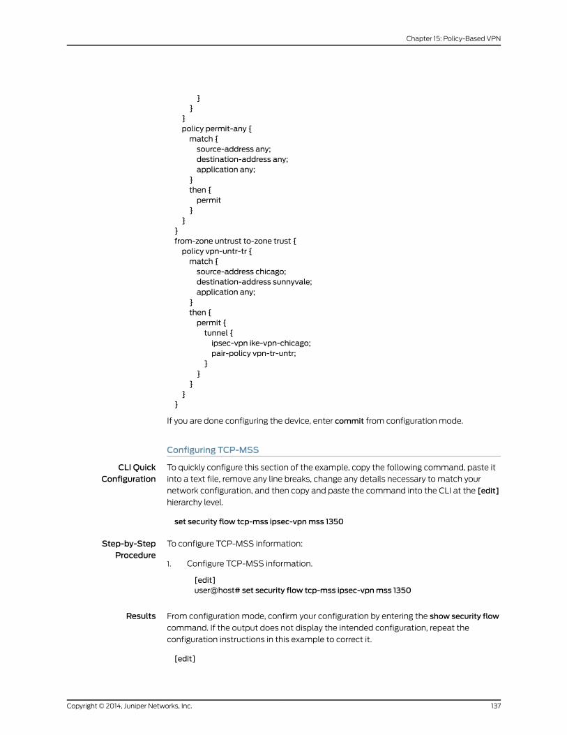
}}
}policy permit-any {match {source-address any;destination-address any;application any;
}then {permit
}}
}from-zone untrust to-zone trust {policy vpn-untr-tr {match {source-address chicago;destination-address sunnyvale;application any;
}then {permit {tunnel {ipsec-vpn ike-vpn-chicago;pair-policy vpn-tr-untr;
}}
}}
}
If you are done configuring the device, enter commit from configuration mode.
Configuring TCP-MSS
CLI QuickConfiguration
To quickly configure this section of the example, copy the following command, paste it
into a text file, remove any line breaks, change any details necessary to match your
network configuration, and then copy and paste the command into the CLI at the [edit]
hierarchy level.
set security flow tcp-mss ipsec-vpnmss 1350
Step-by-StepProcedure
To configure TCP-MSS information:
Configure TCP-MSS information.1.
[edit]user@host# set security flow tcp-mss ipsec-vpnmss 1350
Results From configuration mode, confirm your configuration by entering the show security flow
command. If the output does not display the intended configuration, repeat the
configuration instructions in this example to correct it.
[edit]
137Copyright © 2014, Juniper Networks, Inc.
Chapter 15: Policy-Based VPN
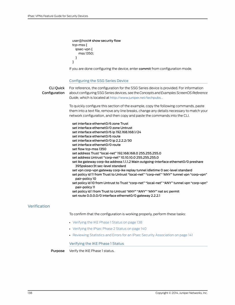
user@host# show security flowtcp-mss {ipsec-vpn {mss 1350;
}}
If you are done configuring the device, enter commit from configuration mode.
Configuring the SSG Series Device
CLI QuickConfiguration
For reference, the configuration for the SSG Series device is provided. For information
about configuring SSG Series devices, see theConceptsandExamplesScreenOSReference
Guide, which is located at http://www.juniper.net/techpubs .
To quickly configure this section of the example, copy the following commands, paste
them into a text file, remove any line breaks, change any details necessary to match your
network configuration, and then copy and paste the commands into the CLI.
set interface ethernet0/6 zone Trustset interface ethernet0/0 zone Untrustset interface ethernet0/6 ip 192.168.168.1/24set interface ethernet0/6 routeset interface ethernet0/0 ip 2.2.2.2/30set interface ethernet0/0 routeset flow tcp-mss 1350set address Trust “local-net” 192.168.168.0 255.255.255.0set address Untrust "corp-net" 10.10.10.0 255.255.255.0set ike gateway corp-ike address 1.1.1.2 Main outgoing-interface ethernet0/0 preshare395psksecr3t sec-level standard
set vpn corp-vpn gateway corp-ike replay tunnel idletime 0 sec-level standardset policy id 11 from Trust to Untrust “local-net” “corp-net” “ANY” tunnel vpn “corp-vpn”pair-policy 10
set policy id 10 fromUntrust to Trust “corp-net” “local-net” “ANY” tunnel vpn “corp-vpn”pair-policy 11
set policy id 1 from Trust to Untrust “ANY” “ANY” “ANY” nat src permitset route 0.0.0.0/0 interface ethernet0/0 gateway 2.2.2.1
Verification
To confirm that the configuration is working properly, perform these tasks:
• Verifying the IKE Phase 1 Status on page 138
• Verifying the IPsec Phase 2 Status on page 140
• Reviewing Statistics and Errors for an IPsec Security Association on page 141
Verifying the IKE Phase 1 Status
Purpose Verify the IKE Phase 1 status.
Copyright © 2014, Juniper Networks, Inc.138
IPsec VPNs Feature Guide for Security Devices

Action NOTE: Before starting the verification process, you need to send traffic froma host in the 10.10.10/24 network to a host in the 192.168.168/24 network.For policy-based VPNs, a separate host must generate the traffic; trafficinitiated from the SRX Series device will not match the VPN policy. Werecommend that the test traffic be froma separate device on one side of theVPN to a second device on the other side of the VPN. For example, initiateping from 10.10.10.10 to 192.168.168.10.
From operational mode, enter the showsecurity ikesecurity-associationscommand. After
obtaining an index number from the command, use the show security ike
security-associations index index_number detail command.
user@host> show security ike security-associationsIndex Remote Address State Initiator cookie Responder cookie Mode4 2.2.2.2 UP 5e1db3f9d50b0de6 e50865d9ebf134f8 Main
user@host> show security ike security-associations index 4 detailIKE peer 2.2.2.2, Index 4, Role: Responder, State: UP Initiator cookie: 5e1db3f9d50b0de6, Responder cookie: e50865d9ebf134f8 Exchange type: Main, Authentication method: Pre-shared-keys Local: 1.1.1.2:500, Remote: 2.2.2.2:500 Lifetime: Expires in 28770 seconds Algorithms: Authentication : sha1 Encryption : aes-128-cbc Pseudo random function: hmac-sha1 Traffic statistics: Input bytes : 852 Output bytes : 856 Input packets : 5 Output packets : 4 Flags: Caller notification sent IPSec security associations: 1 created, 0 deleted Phase 2 negotiations in progress: 0
Meaning The show security ike security-associations command lists all active IKE Phase 1 security
associations (SAs). If no SAs are listed, there was a problem with Phase 1 establishment.
Check the IKE policy parameters and external interface settings in your configuration.
If SAs are listed, review the following information:
• Index—This value is unique for each IKE SA, which you can use in the show security ike
security-associations index detail command to get more information about the SA.
• Remote Address—Verify that the remote IP address is correct.
• State
• UP—The Phase 1 SA has been established.
• DOWN—There was a problem establishing the Phase 1 SA.
• Mode—Verify that the correct mode is being used.
139Copyright © 2014, Juniper Networks, Inc.
Chapter 15: Policy-Based VPN

Verify that the following are correct in your configuration:
• External interfaces (the interface must be the one that receives IKE packets)
• IKE policy parameters
• Preshared key information
• Phase 1 proposal parameters (must match on both peers)
The show security ike security-associations index 1 detail command lists additional
information about the security association with an index number of 1:
• Authentication and encryption algorithms used
• Phase 1 lifetime
• Traffic statistics (can be used to verify that traffic is flowing properly in both directions)
• Initiator and responder role information
NOTE: Troubleshooting is best performedon the peer using the responderrole.
• Number of IPsec SAs created
• Number of Phase 2 negotiations in progress
Verifying the IPsec Phase 2 Status
Purpose Verify the IPsec Phase 2 status.
Action From operational mode, enter the show security ipsec security-associations command.
After obtaining an index number from the command, use the show security ipsec
security-associations index index_number detail command.
user@host> show security ipsec security-associations total configured sa: 2 ID Gateway Port Algorithm SPI Life:sec/kb Mon vsys <2 2.2.2.2 500 ESP:aes-128/sha1 a63eb26f 3565/ unlim - 0 >2 2.2.2.2 500 ESP:aes-128/sha1 a1024ed9 3565/ unlim - 0
user@host> show security ipsec security-associations index 2 detail Virtual-system: Root Local Gateway: 1.1.1.2, Remote Gateway: 2.2.2.2 Local Identity: ipv4_subnet(any:0,[0..7]=10.10.10.0/24) Remote Identity: ipv4_subnet(any:0,[0..7]=192.168.168.0/24) DF-bit: clear Policy-name: vpnpolicy-unt-tr
Direction: inbound, SPI: 2789126767, AUX-SPI: 0 Hard lifetime: Expires in 3558 seconds Lifesize Remaining: Unlimited Soft lifetime: Expires in 2986 seconds Mode: tunnel, Type: dynamic, State: installed, VPN Monitoring: -
Copyright © 2014, Juniper Networks, Inc.140
IPsec VPNs Feature Guide for Security Devices

Protocol: ESP, Authentication: hmac-sha1-96, Encryption: aes-cbc (128 bits)
Anti-replay service: enabled, Replay window size: 32
Direction: outbound, SPI: 2701283033,, AUX-SPI: 0 Hard lifetime: Expires in 3558 seconds Lifesize Remaining: Unlimited Soft lifetime: Expires in 2986 seconds Mode: tunnel, Type: dynamic, State: installed, VPN Monitoring: - Protocol: ESP, Authentication: hmac-sha1-96, Encryption: aes-cbc Anti-replay service: enabled, Replay window size: 32
Meaning The output from the showsecurity ipsecsecurity-associationscommand lists the following
information:
• The ID number is 2. Use this value with the show security ipsec security-associations
index command to get more information about this particular SA.
• There is one IPsec SA pair using port 500, which indicates that no NAT-traversal is
implemented. (NAT-traversal uses port 4500 or another random high-number port.)
• The SPIs, lifetime (in seconds), and usage limits (or lifesize in KB) are shown for both
directions. The 3565/ unlim value indicates that the Phase 2 lifetime expires in 3565
seconds, and that no lifesize has been specified, which indicates that it is unlimited.
Phase 2 lifetime can differ from Phase 1 lifetime, as Phase 2 is not dependent on Phase
1 after the VPN is up.
• VPN monitoring is not enabled for this SA, as indicated by a hyphen in the Mon column.
If VPN monitoring is enabled, U (up) or D (down) is listed.
• The virtual system (vsys) is the root system, and it always lists 0.
The output from the showsecurity ipsecsecurity-associations index16384detailcommand
lists the following information:
• The local identity and remote identity make up the proxy ID for the SA.
A proxy ID mismatch is one of the most common reasons for a Phase 2 failure. For
policy-based VPNs, the proxy ID is derived from the security policy. The local address
and remote address are derived from the address book entries, and the service is derived
from the application configured for the policy. If Phase 2 fails because of a proxy ID
mismatch, you can use the policy to confirm which address book entries are configured.
Verify that the addresses match the information being sent. Check the service to ensure
that the ports match the information being sent.
NOTE: Forsomethird-partyvendors, theproxy IDmustbemanuallyenteredtomatch.
Reviewing Statistics and Errors for an IPsec Security Association
Purpose Review ESP and authentication header counters and errors for an IPsec security
association.
141Copyright © 2014, Juniper Networks, Inc.
Chapter 15: Policy-Based VPN

Action From operational mode, enter the show security ipsec statistics index index_number
command, using the index number of the VPN for which you want to see statistics.
user@host> show security ipsec statistics index 2ESP Statistics: Encrypted bytes: 920 Decrypted bytes: 6208 Encrypted packets: 5 Decrypted packets: 87AH Statistics: Input bytes: 0 Output bytes: 0 Input packets: 0 Output packets: 0Errors: AH authentication failures: 0, Replay errors: 0 ESP authentication failures: 0, ESP decryption failures: 0 Bad headers: 0, Bad trailers: 0
You can also use the show security ipsec statistics command to review statistics and
errors for all SAs.
To clear all IPsec statistics, use the clear security ipsec statistics command.
Meaning If you see packet loss issues across a VPN, you can run the show security ipsec statistics
or show security ipsec statistics detail command several times to confirm that the
encrypted and decrypted packet counters are incrementing. You should also check if the
other error counters are incrementing.
RelatedDocumentation
VPN Overview on page 3•
• Example: Configuring a Route-Based VPN on page 61
• Example: Configuring a Hub-and-Spoke VPN on page 171
• IPsec VPNs Feature Guide for Security Devices
Example: Configuring a Policy-Based VPNwith Both an Initiator and a ResponderBehind a NAT Device
Supported Platforms J Series, LN Series, SRX Series
This example shows how to configure a policy-based VPN with both an initiator and a
responder behind a NAT device to allow data to be securely transferred between a branch
office and the corporate office.
• Requirements on page 143
• Overview on page 143
• Configuration on page 148
• Verification on page 163
Copyright © 2014, Juniper Networks, Inc.142
IPsec VPNs Feature Guide for Security Devices

Requirements
Before you begin, read “VPN Overview” on page 3.
Overview
In this example, you configure a policy-based VPN for a branch office in Chicago, Illinois,
because you want to conserve tunnel resources but still get granular restrictions on VPN
traffic. Users in the branch office will use the VPN to connect to their corporate
headquarters in Sunnyvale, California.
In this example, you configure interfaces, routing options, security zones, security policies
for both an initiator and a responder.
Figure 16 on page 144 shows an example of a topology for a VPN with both an initiator
and a responder behind a NAT device.
143Copyright © 2014, Juniper Networks, Inc.
Chapter 15: Policy-Based VPN
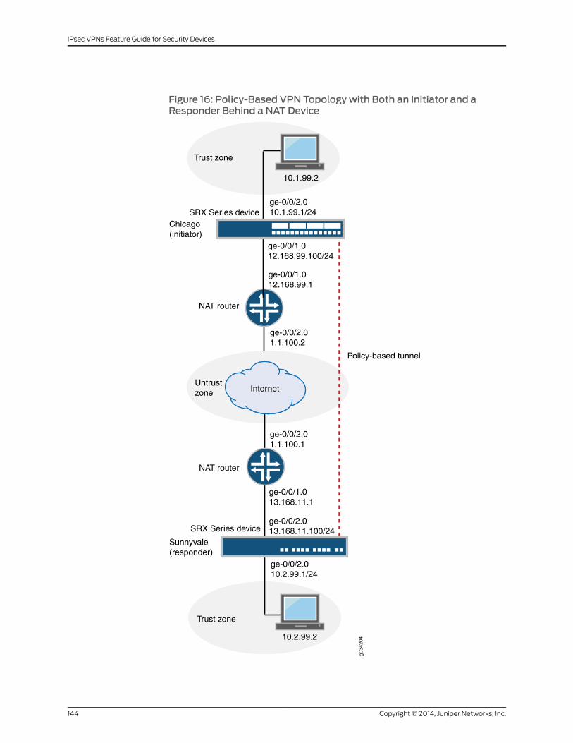
Figure 16: Policy-Based VPN Topology with Both an Initiator and aResponder Behind a NAT Device
Untrustzone
Trust zone
ge-0/0/2.013.168.11.100/24
ge-0/0/2.010.2.99.1/24
SRX Series device
Chicago(initiator)
ge-0/0/2.010.1.99.1/24SRX Series device
Sunnyvale(responder)
ge-0/0/1.012.168.99.100/24
ge-0/0/1.013.168.11.1
ge-0/0/2.01.1.100.1
NAT router
ge-0/0/1.012.168.99.1
ge-0/0/2.01.1.100.2
NAT router
Trust zone
Internet
10.2.99.2
10.1.99.2
g034
204
Policy-based tunnel
Copyright © 2014, Juniper Networks, Inc.144
IPsec VPNs Feature Guide for Security Devices
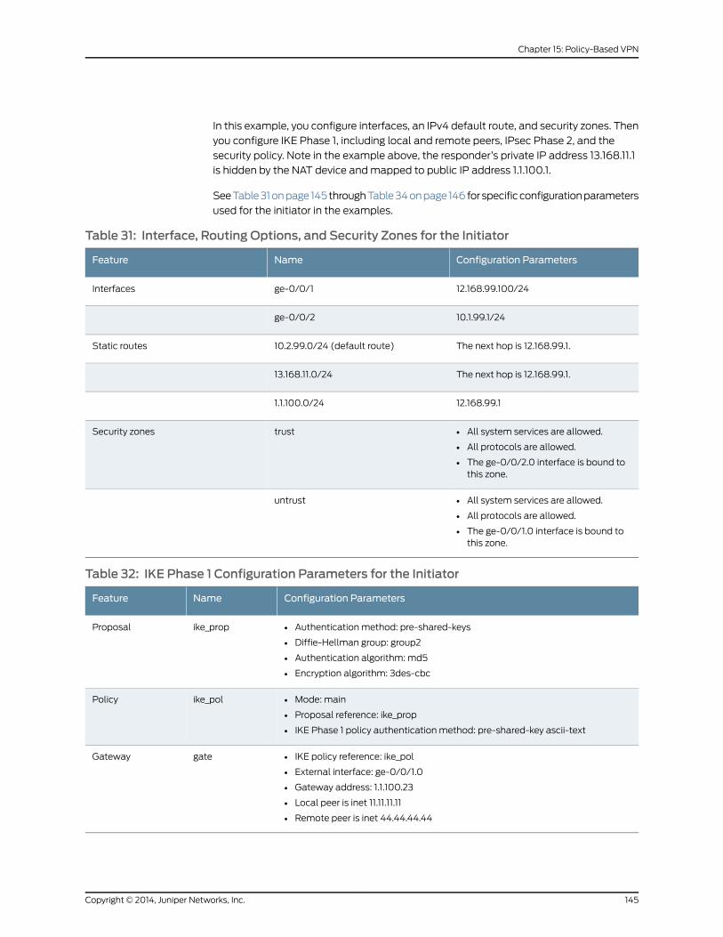
In this example, you configure interfaces, an IPv4 default route, and security zones. Then
you configure IKE Phase 1, including local and remote peers, IPsec Phase 2, and the
security policy. Note in the example above, the responder’s private IP address 13.168.11.1
is hidden by the NAT device and mapped to public IP address 1.1.100.1.
See Table 31 on page 145 through Table 34 on page 146 for specific configuration parameters
used for the initiator in the examples.
Table 31: Interface, Routing Options, and Security Zones for the Initiator
Configuration ParametersNameFeature
12.168.99.100/24ge-0/0/1Interfaces
10.1.99.1/24ge-0/0/2
The next hop is 12.168.99.1.10.2.99.0/24 (default route)Static routes
The next hop is 12.168.99.1.13.168.11.0/24
12.168.99.11.1.100.0/24
• All system services are allowed.
• All protocols are allowed.
• The ge-0/0/2.0 interface is bound tothis zone.
trustSecurity zones
• All system services are allowed.
• All protocols are allowed.
• The ge-0/0/1.0 interface is bound tothis zone.
untrust
Table 32: IKE Phase 1 Configuration Parameters for the Initiator
Configuration ParametersNameFeature
• Authentication method: pre-shared-keys
• Diffie-Hellman group: group2
• Authentication algorithm: md5
• Encryption algorithm: 3des-cbc
ike_propProposal
• Mode: main
• Proposal reference: ike_prop
• IKE Phase 1 policy authentication method: pre-shared-key ascii-text
ike_polPolicy
• IKE policy reference: ike_pol
• External interface: ge-0/0/1.0
• Gateway address: 1.1.100.23
• Local peer is inet 11.11.11.11
• Remote peer is inet 44.44.44.44
gateGateway
145Copyright © 2014, Juniper Networks, Inc.
Chapter 15: Policy-Based VPN

Table 33: IPsec Phase 2 Configuration Parameters for the Initiator
Configuration ParametersNameFeature
• Protocol: esp
• Authentication algorithm: hmac-md5-96
• Encryption algorithm: 3des-cbc
ipsec_propProposal
• Proposal reference: ipsec_prop
• Perfect forward secrecy (PFS): group1
ipsec_polPolicy
• IKE gateway reference: gate
• IPsec policy reference: ipsec_pol
first_vpnVPN
Table 34: Security Policy Configuration Parameters for the Initiator
Configuration ParametersNamePurpose
• Match criteria:
• source-address any
• destination-address any
• application any
• Action: permit tunnel ipsec-vpn first_vpn
pol1The security policy permits tunnel traffic fromthe trust zone to the untrust zone.
• Match criteria:
• source-address any
• destination-address any
• application any
• Action: permit tunnel ipsec-vpn first_vpn
pol1The security policy permits tunnel traffic fromthe untrust zone to the trust zone.
See Table 35 on page 146 through Table 38 on page 148 for specific configuration
parameters used for the responder in the examples.
Table 35: Interface, Routing Options, and Security Zones for the Responder
Configuration ParametersNameFeature
13.168.11.100/24ge-0/0/2Interfaces
10.2.99.1/24ge-0/0/3
The next hop is 13.168.11.1.10.1.99.0/24 (default route)Static routes
The next hop is 13.168.11.1.12.168.99.0/24
13.168.11.11.1.100.0/24
Copyright © 2014, Juniper Networks, Inc.146
IPsec VPNs Feature Guide for Security Devices
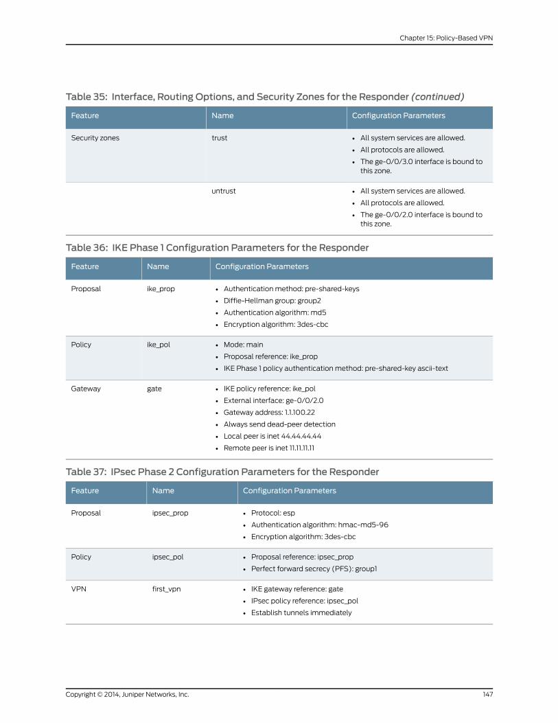
Table 35: Interface, Routing Options, and Security Zones for the Responder (continued)
Configuration ParametersNameFeature
• All system services are allowed.
• All protocols are allowed.
• The ge-0/0/3.0 interface is bound tothis zone.
trustSecurity zones
• All system services are allowed.
• All protocols are allowed.
• The ge-0/0/2.0 interface is bound tothis zone.
untrust
Table 36: IKE Phase 1 Configuration Parameters for the Responder
Configuration ParametersNameFeature
• Authentication method: pre-shared-keys
• Diffie-Hellman group: group2
• Authentication algorithm: md5
• Encryption algorithm: 3des-cbc
ike_propProposal
• Mode: main
• Proposal reference: ike_prop
• IKE Phase 1 policy authentication method: pre-shared-key ascii-text
ike_polPolicy
• IKE policy reference: ike_pol
• External interface: ge-0/0/2.0
• Gateway address: 1.1.100.22
• Always send dead-peer detection
• Local peer is inet 44.44.44.44
• Remote peer is inet 11.11.11.11
gateGateway
Table 37: IPsec Phase 2 Configuration Parameters for the Responder
Configuration ParametersNameFeature
• Protocol: esp
• Authentication algorithm: hmac-md5-96
• Encryption algorithm: 3des-cbc
ipsec_propProposal
• Proposal reference: ipsec_prop
• Perfect forward secrecy (PFS): group1
ipsec_polPolicy
• IKE gateway reference: gate
• IPsec policy reference: ipsec_pol
• Establish tunnels immediately
first_vpnVPN
147Copyright © 2014, Juniper Networks, Inc.
Chapter 15: Policy-Based VPN

Table 38: Security Policy Configuration Parameters for the Responder
Configuration ParametersNamePurpose
• Match criteria:
• source-address any
• destination-address any
• application any
• Action: permit tunnel ipsec-vpn first_vpn
pol1The security policy permits tunnel traffic fromthe trust zone to the untrust zone.
• Match criteria:
• source-address any
• destination-address any
• application any
• Action: permit tunnel ipsec-vpn first_vpn
pol1The security policy permits tunnel traffic fromthe untrust zone to the trust zone.
Configuration
• Configuring Interface, Routing Options, and Security Zones for the Initiator on page 148
• Configuring IKE for the Initiator on page 150
• Configuring IPsec for the Initiator on page 152
• Configuring Security Policies for the Initiator on page 154
• Configuring Interface, Routing Options, and Security Zones for the Responder on page 155
• Configuring IKE for the Responder on page 158
• Configuring IPsec for the Responder on page 160
• Configuring Security Policies for the Responder on page 162
Configuring Interface, Routing Options, and Security Zones for the Initiator
CLI QuickConfiguration
To quickly configure this section of the example, copy the following commands, paste
them into a text file, remove any line breaks, change any details necessary to match your
network configuration, and then copy and paste the commands into the CLI at the [edit]
hierarchy level.
[edit]set interfaces ge-0/0/1 unit 0 family inet address 12.168.99.100/24set interfaces ge-0/0/2 unit 0 family inet address 10.1.99.1/24set routing-options static route 10.2.99.0/24 next-hop 12.168.99.1set routing-options static route 13.168.11.0/24 next-hop 12.168.99.1set routing-options static route 1.1.100.0/24 next-hop 12.168.99.1set security zones security-zone trust host-inbound-traffic system-services allset security zones security-zone trust host-inbound-traffic protocols allset security zones security-zone trust interfaces ge-0/0/2.0set security zones security-zone untrust host-inbound-traffic system-services allset security zones security-zone untrust host-inbound-traffic protocols allset security zones security-zone untrust interfaces ge-0/0/1.0
Copyright © 2014, Juniper Networks, Inc.148
IPsec VPNs Feature Guide for Security Devices

Step-by-StepProcedure
The following example requires you to navigate various levels in the configuration
hierarchy. For instructions on how to do that, see Using the CLI Editor in Configuration
Mode.
To configure interfaces, static routes, and security zones:
1. Configure Ethernet interface information.
[edit]user@host# set interfaces ge-0/0/1 unit 0 family inet address 12.168.99.100/24user@host# set interfaces ge-0/0/2 unit 0 family inet address 10.1.99.1/24
2. Configure static route information.
[edit]user@host# set routing-options static route 10.2.99.0/24 next-hop 12.168.99.1user@host# set routing-options static route 13.168.11.0/24 next-hop 12.168.99.1
3. Configure the trust security zone.
[edit ]user@host# set security zones security-zone trust host-inbound-traffic protocolsall
4. Assign an interface to the trust security zone.
[edit security zones security-zone trust]user@host# set interfaces ge-0/0/2.0
5. Specify system services for the trust security zone.
[edit security zones security-zone trust]user@host# set host-inbound-traffic system-services all
6. Configure the untrust security zone.
[edit security zones security-zone untrust]user@host# set host-inbound-traffic protocols all
7. Assign an interface to the untrust security zone.
[edit security zones security-zone untrust]user@host# set interfaces ge-0/0/1.0
8. Specify system services for the untrust security zone.
[edit security zones security-zone untrust]user@host# set host-inbound-traffic system-services all
Results From configuration mode, confirm your configuration by entering the show interfaces,
show routing-options, and show security zones commands If the output does not display
the intended configuration, repeat the instructions in this example to correct the
configuration.
[edit]user@host# show interfacesge-0/0/1 {unit 0 {family inet {address 12.168.99.100/24;
149Copyright © 2014, Juniper Networks, Inc.
Chapter 15: Policy-Based VPN

}}
}ge-0/0/2 {unit 0 {family inet {address 10.1.99.1/24;
}}
}
[edit]user@host# show routing-optionsstatic {route 10.2.99.0/24 next-hop 12.168.99.1;route 13.168.11.0/24 next-hop 12.168.99.1;route 1.1.100.0/24 next-hop 12.168.99.1;
}
[edit]user@host# show security zonessecurity-zone untrust {host-inbound-traffic {system-services {all;
}protocols{all;}
}interfaces {ge-0/0/1.0.;
}}security-zone trust {host-inbound-traffic {system-services {all;
}protocols {all;}
}interfaces {ge-0/0/2.0;
}
If you are done configuring the device, enter commit from configuration mode.
Configuring IKE for the Initiator
CLI QuickConfiguration
To quickly configure this section of the example, copy the following commands, paste
them into a text file, remove any line breaks, change any details necessary to match your
network configuration, and then copy and paste the commands into the CLI at the [edit]
hierarchy level.
Copyright © 2014, Juniper Networks, Inc.150
IPsec VPNs Feature Guide for Security Devices
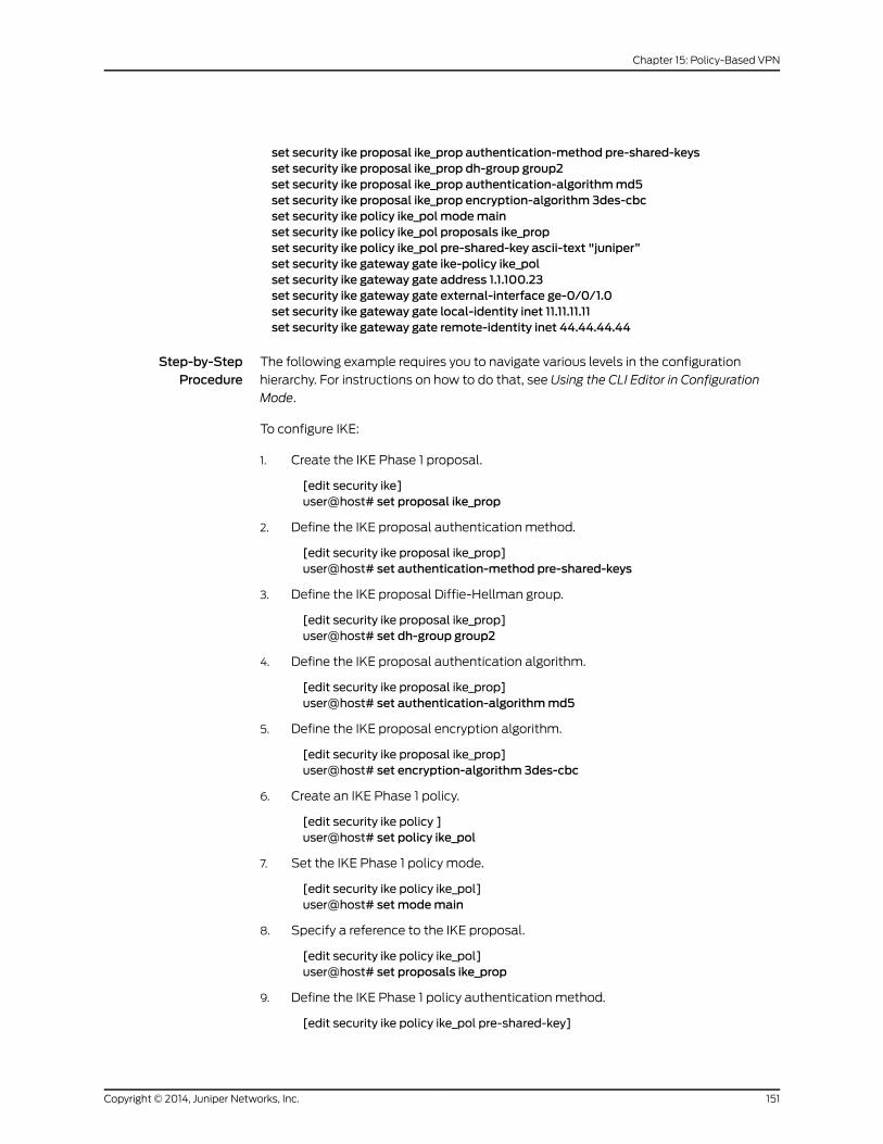
set security ike proposal ike_prop authentication-method pre-shared-keysset security ike proposal ike_prop dh-group group2set security ike proposal ike_prop authentication-algorithmmd5set security ike proposal ike_prop encryption-algorithm 3des-cbcset security ike policy ike_pol modemainset security ike policy ike_pol proposals ike_propset security ike policy ike_pol pre-shared-key ascii-text "juniper”set security ike gateway gate ike-policy ike_polset security ike gateway gate address 1.1.100.23set security ike gateway gate external-interface ge-0/0/1.0set security ike gateway gate local-identity inet 11.11.11.11set security ike gateway gate remote-identity inet 44.44.44.44
Step-by-StepProcedure
The following example requires you to navigate various levels in the configuration
hierarchy. For instructions on how to do that, see Using the CLI Editor in Configuration
Mode.
To configure IKE:
1. Create the IKE Phase 1 proposal.
[edit security ike]user@host# set proposal ike_prop
2. Define the IKE proposal authentication method.
[edit security ike proposal ike_prop]user@host# set authentication-method pre-shared-keys
3. Define the IKE proposal Diffie-Hellman group.
[edit security ike proposal ike_prop]user@host# set dh-group group2
4. Define the IKE proposal authentication algorithm.
[edit security ike proposal ike_prop]user@host# set authentication-algorithmmd5
5. Define the IKE proposal encryption algorithm.
[edit security ike proposal ike_prop]user@host# set encryption-algorithm 3des-cbc
6. Create an IKE Phase 1 policy.
[edit security ike policy ]user@host# set policy ike_pol
7. Set the IKE Phase 1 policy mode.
[edit security ike policy ike_pol]user@host# setmodemain
8. Specify a reference to the IKE proposal.
[edit security ike policy ike_pol]user@host# set proposals ike_prop
9. Define the IKE Phase 1 policy authentication method.
[edit security ike policy ike_pol pre-shared-key]
151Copyright © 2014, Juniper Networks, Inc.
Chapter 15: Policy-Based VPN

user@host# set ascii-text "juniper”
10. Create an IKE Phase 1 gateway and define its external interface.
[edit security ike ]user@host# set gateway gate external-interface ge-0/0/1.0
11. Create an IKE Phase 1 gateway address.
[edit security ike gateway]set gate address 1.1.100.23
12. Define the IKE Phase 1 policy reference.
[edit security ike gateway]set gate ike-policy ike_pol
13. Set local-identity for the local peer.
[edit security ike gateway gate]user@host# set local-identity inet 11.11.11.11
14. Set remote-identity for the responder. This is the responder’s local identity.
[edit security ike gateway gate ]user@host# set remote-identity inet 44.44.44.44
Results From configuration mode, confirm your configuration by entering the show security ike
command. If the output does not display the intended configuration, repeat the
instructions in this example to correct the configuration.
[edit]user@host# show security ikeproposal ike_prop {authentication-method pre-shared-keys;dh-group group2;authentication-algorithmmd5;encryption-algorithm 3des-cbc;
}policy ike_pol {modemain;proposals ike_prop;pre-shared-key ascii-text “juniper”;
}gateway gate {ike-policy ike_pol;address 1.1.100.23;local-identity 11.11.11.11;remote-identity 44.44.44.44;external-interface ge-0/0/1.0;
}
If you are done configuring the device, enter commit from configuration mode.
Configuring IPsec for the Initiator
CLI QuickConfiguration
To quickly configure this section of the example, copy the following commands, paste
them into a text file, remove any line breaks, change any details necessary to match your
Copyright © 2014, Juniper Networks, Inc.152
IPsec VPNs Feature Guide for Security Devices

network configuration, and then copy and paste the commands into the CLI at the [edit]
hierarchy level.
set security ipsec proposal ipsec_prop protocol espset security ipsec proposal ipsec_prop authentication-algorithm hmac-md5-96set security ipsec proposal ipsec_prop encryption-algorithm 3des-cbcset security ipsec policy ipsec_pol perfect-forward-secrecy keys group1set security ipsec policy ipsec_pol proposals ipsec_propset security ipsec vpn first_vpn ike gateway gateset security ipsec vpn first_vpn ike ipsec-policy ipsec_pol
Step-by-StepProcedure
The following example requires you to navigate various levels in the configuration
hierarchy. For instructions on how to do that, see Using the CLI Editor in Configuration
Mode.
To configure IPsec:
1. Create an IPsec Phase 2 proposal.
[edit]user@host# set security ipsec proposal ipsec_prop
2. Specify the IPsec Phase 2 proposal protocol.
[edit security ipsec proposal ipsec_prop]user@host# set protocol esp
3. Specify the IPsec Phase 2 proposal authentication algorithm.
[edit security ipsec proposal ipsec_prop]user@host# set authentication-algorithm hmac-md5-96
4. Specify the IPsec Phase 2 proposal encryption algorithm.
[edit security ipsec proposal ipsec_prop]user@host# set encryption-algorithm 3des-cbc
5. Specify the IPsec Phase 2 proposal reference.
[edit security ipsec policy ipsec_pol]user@host# set proposals ipsec_prop
6. Specify IPsec Phase 2 to use perfect forward secrecy (PFS) group1.
[edit security ipsec policy ipsec_pol ]user@host# set perfect-forward-secrecy keys group1
7. Specify the IKE gateway.
[edit security ipsec]user@host# set vpn first_vpn ike gateway gate
8. Specify the IPsec Phase 2 policy.
[edit security ipsec]user@host# set vpn first_vpn ike ipsec-policy ipsec_pol
Results From configuration mode, confirm your configuration by entering the show security ipsec
command. If the output does not display the intended configuration, repeat the
instructions in this example to correct the configuration.
153Copyright © 2014, Juniper Networks, Inc.
Chapter 15: Policy-Based VPN

[edit]user@host# show security ipsecproposal ipsec_prop {protocol esp;authentication-algorithm hmac-md5-96;encryption-algorithm 3des-cbc;
}policy ipsec_pol {perfect-forward-secrecy {keys group1;proposals ipsec_prop;
}vpn first_vpn {ike {gateway gate;ipsec-policy ipsec_pol;
}}
}
If you are done configuring the device, enter commit from configuration mode.
Configuring Security Policies for the Initiator
CLI QuickConfiguration
To quickly configure this section of the example, copy the following commands, paste
them into a text file, remove any line breaks, change any details necessary to match your
network configuration, and then copy and paste the commands into the CLI at the [edit]
hierarchy level.
set security policies from-zone trust to-zone untrust policy pol1 match source-addressany
setsecuritypolicies from-zonetrust to-zoneuntrustpolicypol1matchdestination-addressany
set security policies from-zone trust to-zone untrust policy pol1 match application anyset security policies from-zone trust to-zone untrust policy pol1 then permit tunnelipsec-vpn first_vpn
set security policies from-zone untrust to-zone trust policy pol1 match source-addressany
setsecuritypolicies from-zoneuntrust to-zonetrustpolicypol1matchdestination-addressany
set security policies from-zone untrust to-zone trust policy pol1 match application anyset security policies from-zone untrust to-zone trust policy pol1 then permit tunnelipsec-vpn first_vpn
Step-by-StepProcedure
The following example requires you to navigate various levels in the configuration
hierarchy. For instructions on how to do that, see Using the CLI Editor in Configuration
Mode.
To configure security policies:
1. Create the security policy to permit traffic from the trust zone to the untrust zone.
[edit security policies from-zone trust to-zone untrust]user@host# set policy pol1 match source-address anyuser@host# set policy pol1 match destination-address any
Copyright © 2014, Juniper Networks, Inc.154
IPsec VPNs Feature Guide for Security Devices
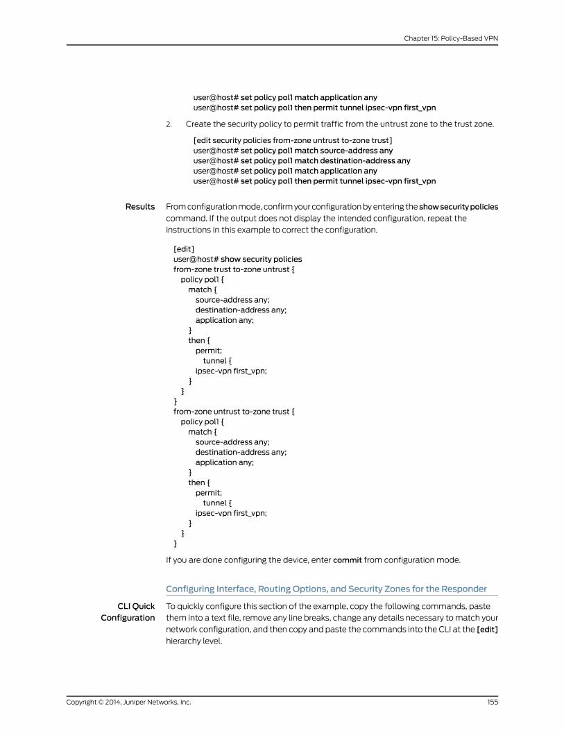
user@host# set policy pol1 match application anyuser@host# set policy pol1 then permit tunnel ipsec-vpn first_vpn
2. Create the security policy to permit traffic from the untrust zone to the trust zone.
[edit security policies from-zone untrust to-zone trust]user@host# set policy pol1 match source-address anyuser@host# set policy pol1 match destination-address anyuser@host# set policy pol1 match application anyuser@host# set policy pol1 then permit tunnel ipsec-vpn first_vpn
Results From configuration mode, confirm your configuration by entering the showsecuritypolicies
command. If the output does not display the intended configuration, repeat the
instructions in this example to correct the configuration.
[edit]user@host# show security policiesfrom-zone trust to-zone untrust {policy pol1 {match {source-address any;destination-address any;application any;
}then {permit;tunnel {
ipsec-vpn first_vpn;}
}}from-zone untrust to-zone trust {policy pol1 {match {source-address any;destination-address any;application any;
}then {permit;tunnel {
ipsec-vpn first_vpn;}
}}
If you are done configuring the device, enter commit from configuration mode.
Configuring Interface, Routing Options, and Security Zones for the Responder
CLI QuickConfiguration
To quickly configure this section of the example, copy the following commands, paste
them into a text file, remove any line breaks, change any details necessary to match your
network configuration, and then copy and paste the commands into the CLI at the [edit]
hierarchy level.
155Copyright © 2014, Juniper Networks, Inc.
Chapter 15: Policy-Based VPN

set interfaces ge-0/0/2 unit 0 family inet address 13.168.11.100/24set interfaces ge-0/0/3 unit 0 family inet address 10.2.99.1/24set routing-options static route 10.1.99.0/24 next-hop 13.168.11.1set routing-options static route 12.168.99.0/24 next-hop 13.168.11.1set routing-options static route 1.1.100.0/24 next-hop 13.168.11.1set security zones security-zone untrust host-inbound-traffic system-services allset security zones security-zone untrust host-inbound-traffic protocols allset security zones security-zone untrust interfaces ge-0/0/2.0set security zones security-zone trust host-inbound-traffic system-services allset security zones security-zone trust host-inbound-traffic protocols allset security zones security-zone trust interfaces ge-0/0/3.0
Step-by-StepProcedure
The following example requires you to navigate various levels in the configuration
hierarchy. For instructions on how to do that, see Using the CLI Editor in Configuration
Mode.
To configure interfaces, static routes, security zones, and security policies:
1. Configure Ethernet interface information.
[edit]user@host# set interfaces ge-0/0/2 unit 0 family inet address 13.168.11.100/24user@host# set interfaces ge-0/0/3 unit 0 family inet address 10.2.99.1/24
2. Configure static route information.
[edit]user@host# set routing-options static route 10.1.99.0/24 next-hop 13.168.11.1user@host# set routing-options static route 12.168.99.0/24 next-hop 13.168.11.1user@host# set routing-options static route 1.1.100.0/24 next-hop 13.168.11.1
3. Configure the untrust security zone.
[edit ]user@host#set security zonessecurity-zoneuntrusthost-inbound-trafficprotocolsall
4. Assign an interface to the untrust security zone.
[edit security zones security-zone untrust]user@host# set interfaces ge-0/0/2.0
5. Specify allowed system services for the untrust security zone.
[edit security zones security-zone untrust]user@host# set host-inbound-traffic system-services all
6. Configure the trust security zone.
[edit]user@host# set security zones security-zone trust host-inbound-traffic protocolsall
7. Assign an interface to the trust security zone.
[edit security zones security-zone trust]user@host# set interfaces ge-0/0/3.0
8. Specify allowed system services for the trust security zone.
[edit security zones security-zone trust]
Copyright © 2014, Juniper Networks, Inc.156
IPsec VPNs Feature Guide for Security Devices
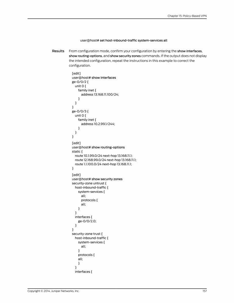
user@host# set host-inbound-traffic system-services all
Results From configuration mode, confirm your configuration by entering the show interfaces,
show routing-options, and showsecurity zones commands. If the output does not display
the intended configuration, repeat the instructions in this example to correct the
configuration.
[edit]user@host# show interfacesge-0/0/2 {unit 0 {family inet {address 13.168.11.100/24;
}}
}ge-0/0/3 {unit 0 {family inet {address 10.2.99.1/244;
}}
}
[edit]user@host# show routing-optionsstatic {route 10.1.99.0/24 next-hop 13.168.11.1;route 12.168.99.0/24 next-hop 13.168.11.1;route 1.1.100.0/24 next-hop 13.168.11.1;
}
[edit]user@host# show security zonessecurity-zone untrust {host-inbound-traffic {system-services {all;protocols {all;
}}interfaces {ge-0/0/2.0;
}}security-zone trust {host-inbound-traffic {system-services {all;
}protocols {all;}
}interfaces {
157Copyright © 2014, Juniper Networks, Inc.
Chapter 15: Policy-Based VPN

ge-0/0/3.0;}
}
If you are done configuring the device, enter commit from configuration mode.
Configuring IKE for the Responder
CLI QuickConfiguration
To quickly configure this section of the example, copy the following commands, paste
them into a text file, remove any line breaks, change any details necessary to match your
network configuration, and then copy and paste the commands into the CLI at the [edit]
hierarchy level.
set security ike proposal ike_prop authentication-method pre-shared-keysset security ike proposal ike_prop dh-group group2set security ike proposal ike_prop authentication-algorithmmd5set security ike proposal ike_prop encryption-algorithm 3des-cbcset security ike policy ike_pol modemainset security ike policy ike_pol proposals ike_propset security ike policy ike_pol pre-shared-key ascii-text "juniper"set security ike gateway gate ike-policy ike_polset security ike gateway gate address 1.1.100.22set security ike gateway gate dead-peer-detection always-sendset security ike gateway gate external-interface ge-0/0/2.0set security ike gateway gate local-identity inet 44.44.44.44set security ike gateway gate remote-identity inet 11.11.11.11
Step-by-StepProcedure
The following example requires you to navigate various levels in the configuration
hierarchy. For instructions on how to do that, see Using the CLI Editor in Configuration
Mode.
To configure IKE:
1. Create the IKE Phase 1 proposal.
[edit security ike]user@host# set proposal ike-phase1-proposal
2. Define the IKE proposal authentication method.
[edit security ike proposal ike_prop]user@host# set authentication-method pre-shared-key
3. Define the IKE proposal Diffie-Hellman group.
[edit security ike proposal ike_prop]user@host# set dh-group group2
4. Define the IKE proposal authentication algorithm.
[edit security ike proposal ike_prop]user@host# set authentication-algorithmmd5
5. Define the IKE proposal encryption algorithm.
[edit security ike proposal ike_prop]user@host# set encryption-algorithm 3des-cbc
6. Create an IKE Phase 1 policy.
Copyright © 2014, Juniper Networks, Inc.158
IPsec VPNs Feature Guide for Security Devices

[edit security ike]user@host# set policy ike_pol
7. Set the IKE Phase 1 policy mode.
[edit security ike policy ike_pol]user@host# setmodemain
8. Specify a reference to the IKE proposal.
[edit security ike policy ike_pol]user@host# set proposals ike_prop
9. Define the IKE Phase 1 policy authentication method.
[edit security ike policy ike_pol proposals ike_prop set security ike policy ike_polpre-shared-key]
user@host# set ascii-text "juniper"
10. Create an IKE Phase 1 gateway and define its external interface.
[edit security ike]user@host# set security ike gateway gate external-interface ge-0/0/2.0
11. Define the IKE Phase 1 policy reference.
[edit security ike gateway]user@host# set gate ike-policy ike_pol
12. Create an IKE Phase 1 gateway address.
[edit security ike gateway]user@host# set gate address 1.1.100.22
13. Set local-identity for the local peer (initiator).
[edit security ike gateway gate]user@host# set local-identity inet 44.44.44.44
14. Set remote-identity for the responder. This is the responder’s local identity.
[edit security ike gateway gate]user@host# set remote-identity inet 11.11.11.11
15. Set dead peer detection to detect whether the peer is up or down.
[edit security ike gateway gate]user@host# set dead-peer-detection always-send
Results From configuration mode, confirm your configuration by entering the show security ike
command. If the output does not display the intended configuration, repeat the
instructions in this example to correct the configuration.
[edit]user@host# show security ikeproposal ike_prop {authentication-method pre-shared-keys;dh-group group2;authentication-algorithmmd5;encryption-algorithm 3des-cbc;
}policy ike_pol {
159Copyright © 2014, Juniper Networks, Inc.
Chapter 15: Policy-Based VPN

modemain;proposals ike_prop;pre-shared-key ascii-text "juniper";
}gateway gate {ike-policy ike_pol;address 1.1.100.22;dead-peer-detection always-send;external-interface ge-0/0/2.0;local-identity inet 44.44.44.44;remote-identity inet 11.11.11.11;
}
If you are done configuring the device, enter commit from configuration mode.
Configuring IPsec for the Responder
CLI QuickConfiguration
To quickly configure this section of the example, copy the following commands, paste
them into a text file, remove any line breaks, change any details necessary to match your
network configuration, and then copy and paste the commands into the CLI at the [edit]
hierarchy level.
set security ipsec proposal ipsec_prop protocol espset security ipsec proposal ipsec_prop authentication-algorithm hmac-md5-96set security ipsec proposal ipsec_prop encryption-algorithm 3des-cbcset security ipsec policy ipsec_pol perfect-forward-secrecy keys group1set security ipsec policy ipsec_pol proposals ipsec_propset security ipsec vpn first_vpn ike gateway gateset security ipsec vpn first_vpn ike ipsec-policy ipsec_polset security ipsec vpn first_vpn establish-tunnels immediately
Step-by-StepProcedure
The following example requires you to navigate various levels in the configuration
hierarchy. For instructions on how to do that, see Using the CLI Editor in Configuration
Mode.
To configure IPsec:
1. Create an IPsec Phase 2 proposal.
[edit]user@host# set security ipsec proposal ipsec_prop
2. Specify the IPsec Phase 2 proposal protocol.
[edit security security ipsec proposal ipsec_prop]user@host# set protocol esp
3. Specify the IPsec Phase 2 proposal authentication algorithm.
[edit security ipsec proposal ipsec_prop]user@host# set authentication-algorithm hmac-md5-96
4. Specify the IPsec Phase 2 proposal encryption algorithm.
[edit security ipsec proposal ipsec_prop]user@host# set encryption-algorithm 3des-cbc
5. Set IPsec Phase 2 to use perfect forward secrecy (PFS) group1.
Copyright © 2014, Juniper Networks, Inc.160
IPsec VPNs Feature Guide for Security Devices

[edit security ipsec policy ipsec_pol]user@host# set perfect-forward-secrecy keys group1
6. Create the IPsec Phase 2 policy.
[edit security ipsec]user@host# set policy ipsec_pol
7. Specify the IPsec Phase 2 proposal reference.
[edit security ipsec policy ipsec_pol]user@host# set proposals ipsec_prop
8. Specify the IKE gateway.
[edit security ipsec]user@host# set vpn first_vpn ike gateway gate
9. Specify the IPsec Phase 2 policy.
[edit security ipsec]user@host# set vpn first_vpn ike ipsec-policy ipsec_pol
10. Specify that the tunnel be brought up immediately without a verification packet.
[edit security ipsec]user@host# set security ipsec vpn first_vpn establish-tunnels immediately
Results From configuration mode, confirm your configuration by entering the show security ipsec
command. If the output does not display the intended configuration, repeat the
instructions in this example to correct the configuration.
[edit]user@host# show security ipsecproposal ipsec_prop {protocol esp;authentication-algorithm hmac-md5-96;encryption-algorithm 3des-cbc;
}policy ipsec_pol {perfect-forward-secrecy {keys group1;
}proposals ipsec_prop;
}vpn first_vpn {ike {gateway gate;ipsec-policy ipsec_pol;establish-tunnels immediately;
}}
If you are done configuring the device, enter commit from configuration mode.
161Copyright © 2014, Juniper Networks, Inc.
Chapter 15: Policy-Based VPN

Configuring Security Policies for the Responder
CLI QuickConfiguration
To quickly configure this section of the example, copy the following commands, paste
them into a text file, remove any line breaks, change any details necessary to match your
network configuration, and then copy and paste the commands into the CLI at the [edit]
hierarchy level.
set security policies from-zone trust to-zone untrust policy pol1 match source-addressany
setsecuritypolicies from-zonetrust to-zoneuntrustpolicypol1matchdestination-addressany
set security policies from-zone trust to-zone untrust policy pol1 match application anyset security policies from-zone trust to-zone untrust policy pol1 then permit tunnelipsec-vpn first_vpn
set security policies from-zone untrust to-zone trust policy pol1 match source-addressany
setsecuritypolicies from-zoneuntrust to-zonetrustpolicypol1matchdestination-addressany
set security policies from-zone untrust to-zone trust policy pol1 match application anyset security policies from-zone untrust to-zone trust policy pol1 then permit tunnelipsec-vpn first_vpn
Step-by-StepProcedure
The following example requires you to navigate various levels in the configuration
hierarchy. For instructions on how to do that, see Using the CLI Editor in Configuration
Mode.
To configure security policies:
1. Create the security policy to permit traffic from the trust zone to the untrust zone.
[edit security policies from-zone trust to-zone untrust]user@host# set policy pol1 match source-address anyuser@host# set policy pol1 match destination-address anyuser@host# set policy pol1 match application anyuser@host# set policy pol1 then permit tunnel ipsec-vpn first_vpn
2. Create the security policy to permit traffic from the untrust zone to the trust zone.
[edit security policies from-zone untrust to-zone trust]user@host# set policy pol1 match source-address anyuser@host# set policy pol1 match destination-address anyuser@host# set policy pol1 match application anyuser@host# set policy pol1 then permit tunnel ipsec-vpn first_vpn
Results From configuration mode, confirm your configuration by entering the showsecuritypolicies
command. If the output does not display the intended configuration, repeat the
instructions in this example to correct the configuration.
[edit]user@host# show security policiesfrom-zone trust to-zone untrust {policy pol1 {match {source-address any;destination-address any;
Copyright © 2014, Juniper Networks, Inc.162
IPsec VPNs Feature Guide for Security Devices

application any;}then {permit;tunnel {
ipsec-vpn first_vpn;}
}}from-zone untrust to-zone trust {policy pol1 {match {source-address any;destination-address any;application any;
}then {permit;tunnel {
ipsec-vpn first_vpn;}
}}
If you are done configuring the device, enter commit from configuration mode.
Verification
To confirm that the configuration is working properly, perform these tasks:
• Verifying the IKE Phase 1 Status for the Initiator on page 163
• Verifying IPsec Security Associations for the Initiator on page 165
• Verifying the IKE Phase 1 Status for the Responder on page 166
• Verifying IPsec Security Associations for the Responder on page 168
Verifying the IKE Phase 1 Status for the Initiator
Purpose Verify the IKE Phase 1 status.
Action NOTE: Before starting the verification process, youmust send traffic from ahost in the 10.1.99.0 network to a host in the 10.2.99.0 network. Forroute-based VPNs, traffic can be initiated by the SRX Series device throughthe tunnel. We recommend that when testing IPsec tunnels, test traffic besent from a separate device on one side of the VPN to a second device ontheother sideof theVPN.Forexample, initiateapingoperation from10.1.99.2to 10.2.99.2.
163Copyright © 2014, Juniper Networks, Inc.
Chapter 15: Policy-Based VPN
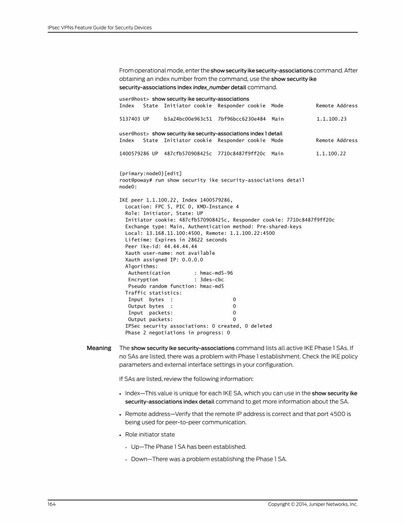
From operational mode, enter the showsecurity ikesecurity-associationscommand. After
obtaining an index number from the command, use the show security ike
security-associations index index_number detail command.
user@host> show security ike security-associationsIndex State Initiator cookie Responder cookie Mode Remote Address
5137403 UP b3a24bc00e963c51 7bf96bcc6230e484 Main 1.1.100.23
user@host> show security ike security-associations index 1 detailIndex State Initiator cookie Responder cookie Mode Remote Address
1400579286 UP 487cfb570908425c 7710c8487f9ff20c Main 1.1.100.22
{primary:node0}[edit]root@poway# run show security ike security-associations detail node0:
IKE peer 1.1.100.22, Index 1400579286, Location: FPC 5, PIC 0, KMD-Instance 4 Role: Initiator, State: UP Initiator cookie: 487cfb570908425c, Responder cookie: 7710c8487f9ff20c Exchange type: Main, Authentication method: Pre-shared-keys Local: 13.168.11.100:4500, Remote: 1.1.100.22:4500 Lifetime: Expires in 28622 seconds Peer ike-id: 44.44.44.44 Xauth user-name: not available Xauth assigned IP: 0.0.0.0 Algorithms: Authentication : hmac-md5-96 Encryption : 3des-cbc Pseudo random function: hmac-md5 Traffic statistics: Input bytes : 0 Output bytes : 0 Input packets: 0 Output packets: 0 IPSec security associations: 0 created, 0 deleted Phase 2 negotiations in progress: 0
Meaning The show security ike security-associations command lists all active IKE Phase 1 SAs. If
no SAs are listed, there was a problem with Phase 1 establishment. Check the IKE policy
parameters and external interface settings in your configuration.
If SAs are listed, review the following information:
• Index—This value is unique for each IKE SA, which you can use in the show security ike
security-associations index detail command to get more information about the SA.
• Remote address—Verify that the remote IP address is correct and that port 4500 is
being used for peer-to-peer communication.
• Role initiator state
• Up—The Phase 1 SA has been established.
• Down—There was a problem establishing the Phase 1 SA.
Copyright © 2014, Juniper Networks, Inc.164
IPsec VPNs Feature Guide for Security Devices
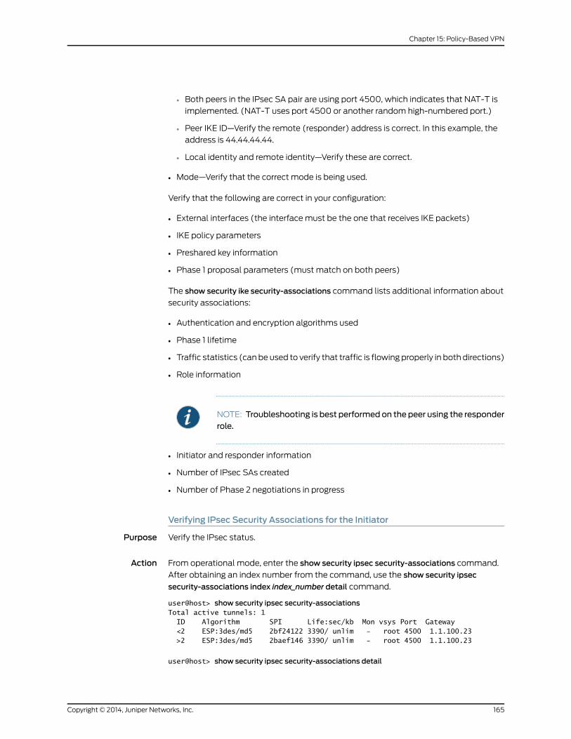
• Both peers in the IPsec SA pair are using port 4500, which indicates that NAT-T is
implemented. (NAT-T uses port 4500 or another random high-numbered port.)
• Peer IKE ID—Verify the remote (responder) address is correct. In this example, the
address is 44.44.44.44.
• Local identity and remote identity—Verify these are correct.
• Mode—Verify that the correct mode is being used.
Verify that the following are correct in your configuration:
• External interfaces (the interface must be the one that receives IKE packets)
• IKE policy parameters
• Preshared key information
• Phase 1 proposal parameters (must match on both peers)
The show security ike security-associations command lists additional information about
security associations:
• Authentication and encryption algorithms used
• Phase 1 lifetime
• Traffic statistics (can be used to verify that traffic is flowing properly in both directions)
• Role information
NOTE: Troubleshooting is best performedon the peer using the responderrole.
• Initiator and responder information
• Number of IPsec SAs created
• Number of Phase 2 negotiations in progress
Verifying IPsec Security Associations for the Initiator
Purpose Verify the IPsec status.
Action From operational mode, enter the show security ipsec security-associations command.
After obtaining an index number from the command, use the show security ipsec
security-associations index index_number detail command.
user@host> show security ipsec security-associationsTotal active tunnels: 1 ID Algorithm SPI Life:sec/kb Mon vsys Port Gateway <2 ESP:3des/md5 2bf24122 3390/ unlim - root 4500 1.1.100.23 >2 ESP:3des/md5 2baef146 3390/ unlim - root 4500 1.1.100.23
user@host> show security ipsec security-associations detail
165Copyright © 2014, Juniper Networks, Inc.
Chapter 15: Policy-Based VPN

Local Gateway: 12.168.99.100, Remote Gateway: 1.1.100.23 Local Identity: ipv4_subnet(any:0,[0..7]=0.0.0.0/0) Remote Identity: ipv4_subnet(any:0,[0..7]=0.0.0.0/0) Version: IKEv1 DF-bit: clear Policy-name: pol1
Location: FPC 5, PIC 0, KMD-Instance 4 Direction: inbound, SPI: 2bf24122, AUX-SPI: 0 , VPN Monitoring: - Hard lifetime: Expires in 3388 seconds Lifesize Remaining: Unlimited Soft lifetime: Expires in 2801 seconds Mode: Tunnel, Type: dynamic, State: installed Protocol: ESP, Authentication: hmac-md5-96, Encryption: 3des-cbc Anti-replay service: counter-based enabled, Replay window size: 64
Location: FPC 5, PIC 0, KMD-Instance 4 Direction: outbound, SPI: 2baef146, AUX-SPI: 0 , VPN Monitoring: - Hard lifetime: Expires in 3388 seconds Lifesize Remaining: Unlimited Soft lifetime: Expires in 2801 seconds Mode: Tunnel, Type: dynamic, State: installed Protocol: ESP, Authentication: hmac-md5-96, Encryption: 3des-cbc Anti-replay service: counter-based enabled, Replay window size: 64
Meaning The output from the showsecurity ipsecsecurity-associationscommand lists the following
information:
• The remote gateway has a NAT address of 1.1.100.23.
• Both peers in the IPsec SA pair are using port 4500, which indicates that NAT-T is
implemented. (NAT-T uses port 4500 or another random high-numbered port.).
• The SPIs, lifetime (in seconds), and usage limits (or lifesize in KB) are shown for both
directions. The 3390/ unlimited value indicates that the Phase 2 lifetime expires in
3390 seconds, and that no lifesize has been specified, which indicates that it is
unlimited. Phase 2 lifetime can differ from Phase 1 lifetime, as Phase 2 is not dependent
on Phase 1 after the VPN is up.
• VPN monitoring is not enabled for this SA, as indicated by a hyphen in the Mon column.
If VPN monitoring is enabled, U indicates that monitoring is up, and D indicates that
monitoring is down.
• The virtual system (vsys) is the root system, and it always lists 0.
Verifying the IKE Phase 1 Status for the Responder
Purpose Verify the IKE Phase 1 status.
Action From operational mode, enter the showsecurity ikesecurity-associationscommand. After
obtaining an index number from the command, use the show security ike
security-associations index index_number detail command.
user@host> show security ike security-associations
Copyright © 2014, Juniper Networks, Inc.166
IPsec VPNs Feature Guide for Security Devices

Index State Initiator cookie Responder cookie Mode Remote Address
5802591 UP d31d6833108fd69f 9ddfe2ce133086aa Main 1.0.0.1
user@host> show security ike security-associations index 1 detailIKE peer 1.1.100.23, Index 1400579287, Location: FPC 5, PIC 0, KMD-Instance 4 Role: Responder, State: UP Initiator cookie: 487cfb570908425c, Responder cookie: 7710c8487f9ff20c Exchange type: Main, Authentication method: Pre-shared-keys Local: 12.168.99.100:4500, Remote: 1.1.100.23:4500 Lifetime: Expires in 28587 seconds Peer ike-id: 11.11.11.11 Xauth user-name: not available Xauth assigned IP: 0.0.0.0 Algorithms: Authentication : hmac-md5-96 Encryption : 3des-cbc Pseudo random function: hmac-md5 Traffic statistics: Input bytes : 0 Output bytes : 0 Input packets: 0 Output packets: 0 IPSec security associations: 0 created, 0 deleted Phase 2 negotiations in progress: 0
Negotiation type: Quick mode, Role: Responder, Message ID: 0 Local: 71.1.1.1:4500, Remote: 1.0.0.1:4500 Local identity: [email protected] Remote identity: [email protected] Flags: IKE SA is created
Meaning The show security ike security-associations command lists all active IKE Phase 1 SAs. If
no SAs are listed, there was a problem with Phase 1 establishment. Check the IKE policy
parameters and external interface settings in your configuration.
If SAs are listed, review the following information:
• Index—This value is unique for each IKE SA, which you can use in the show security ike
security-associations index detail command to get more information about the SA.
• Remote address—Verify that the remote IP address is correct and that port 4500 is
being used for peer-to-peer communication.
• Role responder state
• Up—The Phase 1 SA has been established.
• Down—There was a problem establishing the Phase 1 SA.
• Peer IKE ID—Verify the local (initiator) address for the peer is correct. In this example,
the address is 11.11.11.11.
• Local identity and remote identity—Verify these are correct.
• Mode—Verify that the correct mode is being used.
Verify that the following are correct in your configuration:
167Copyright © 2014, Juniper Networks, Inc.
Chapter 15: Policy-Based VPN
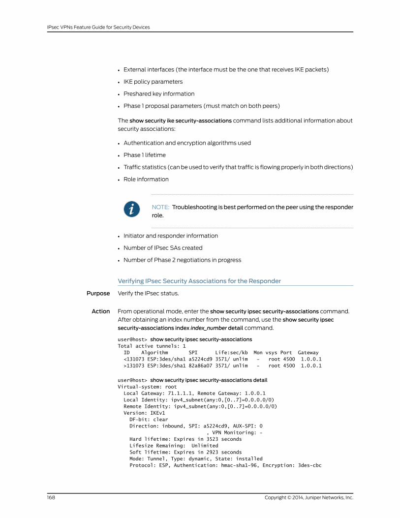
• External interfaces (the interface must be the one that receives IKE packets)
• IKE policy parameters
• Preshared key information
• Phase 1 proposal parameters (must match on both peers)
The show security ike security-associations command lists additional information about
security associations:
• Authentication and encryption algorithms used
• Phase 1 lifetime
• Traffic statistics (can be used to verify that traffic is flowing properly in both directions)
• Role information
NOTE: Troubleshooting is best performedon the peer using the responderrole.
• Initiator and responder information
• Number of IPsec SAs created
• Number of Phase 2 negotiations in progress
Verifying IPsec Security Associations for the Responder
Purpose Verify the IPsec status.
Action From operational mode, enter the show security ipsec security-associations command.
After obtaining an index number from the command, use the show security ipsec
security-associations index index_number detail command.
user@host> show security ipsec security-associationsTotal active tunnels: 1 ID Algorithm SPI Life:sec/kb Mon vsys Port Gateway <131073 ESP:3des/sha1 a5224cd9 3571/ unlim - root 4500 1.0.0.1 >131073 ESP:3des/sha1 82a86a07 3571/ unlim - root 4500 1.0.0.1
user@host> show security ipsec security-associations detailVirtual-system: root Local Gateway: 71.1.1.1, Remote Gateway: 1.0.0.1 Local Identity: ipv4_subnet(any:0,[0..7]=0.0.0.0/0) Remote Identity: ipv4_subnet(any:0,[0..7]=0.0.0.0/0) Version: IKEv1 DF-bit: clear Direction: inbound, SPI: a5224cd9, AUX-SPI: 0 , VPN Monitoring: - Hard lifetime: Expires in 3523 seconds Lifesize Remaining: Unlimited Soft lifetime: Expires in 2923 seconds Mode: Tunnel, Type: dynamic, State: installed Protocol: ESP, Authentication: hmac-sha1-96, Encryption: 3des-cbc
Copyright © 2014, Juniper Networks, Inc.168
IPsec VPNs Feature Guide for Security Devices

Anti-replay service: counter-based enabled, Replay window size: 64
Direction: outbound, SPI: 82a86a07, AUX-SPI: 0 , VPN Monitoring: - Hard lifetime: Expires in 3523 seconds Lifesize Remaining: Unlimited Soft lifetime: Expires in 2923 seconds Mode: Tunnel, Type: dynamic, State: installed Protocol: ESP, Authentication: hmac-sha1-96, Encryption: 3des-cbc Anti-replay service: counter-based enabled, Replay window size: 64
Meaning The output from the showsecurity ipsecsecurity-associationscommand lists the following
information:
• The remote gateway has a NAT address of 1.0.0.1.
• Both peers in the IPsec SA pair are using port 4500, which indicates that NAT-T is
implemented. (NAT-T uses port 4500 or another random high-numbered port.)
• The SPIs, lifetime (in seconds), and usage limits (or lifesize in KB) are shown for both
directions. The 3571/ unlim value indicates that the Phase 2 lifetime expires in 3571
seconds, and that no lifesize has been specified, which indicates that it is unlimited.
Phase 2 lifetime can differ from Phase 1 lifetime, as Phase 2 is not dependent on Phase
1 after the VPN is up.
• VPN monitoring is not enabled for this SA, as indicated by a hyphen in the Mon column.
If VPN monitoring is enabled, U indicates that monitoring is up, and D indicates that
monitoring is down.
• The virtual system (vsys) is the root system, and it always lists 0.
RelatedDocumentation
• VPN Overview on page 3
• Understanding NAT-T on page 49
• Example: Configuring a Route-Based VPN with Only the Responder Behind a NAT
Device on page 95
• IPsec VPNs Feature Guide for Security Devices
169Copyright © 2014, Juniper Networks, Inc.
Chapter 15: Policy-Based VPN

Copyright © 2014, Juniper Networks, Inc.170
IPsec VPNs Feature Guide for Security Devices
CHAPTER 16
Hub-and-Spoke VPN
• Example: Configuring a Hub-and-Spoke VPN on page 171
Example: Configuring a Hub-and-Spoke VPN
Supported Platforms J Series, LN Series, SRX Series
This example shows how to configure a hub-and-spoke IPsec VPN for an enterprise-class
deployment.
• Requirements on page 171
• Overview on page 171
• Configuration on page 177
• Verification on page 197
Requirements
This example uses the following hardware:
• SRX240 device
• SRX5800 device
• SSG140 device
Before you begin, read “VPN Overview” on page 3.
Overview
This example describes how to configure a hub-and-spoke VPN typically found in branch
deployments. The hub is the corporate office, and there are two spokes—a branch office
in Sunnyvale, California, and a branch office in Westford, Massachusetts. Users in the
branch offices will use the VPN to securely transfer data with the corporate office.
Figure 17 on page 172 shows an example of a hub-and-spoke VPN topology. In this topology,
an SRX5800 device is located at the corporate office. An SRX240 device is located at
the Westford branch, and an SSG140 device is located at the Sunnyvale branch.
171Copyright © 2014, Juniper Networks, Inc.
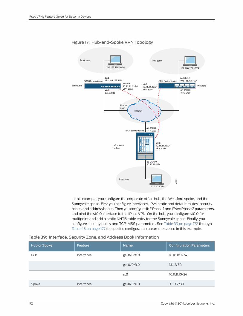
Figure 17: Hub-and-Spoke VPN Topology
Untrustzone
Internet
Trust zone
192.168.178.10/24
ge-0/0/3.0192.168.178.1/24
Trust zone
192.168.168.10/24
e0/6192.168.168.1/24
ge-0/0/0.03.3.3.2/30
e0/02.2.2.2/30
Trust zone
tunnel110.11.11.11/24VPN zone
st0.010.11.11.12/24VPN zone
SSG Series device SRX Series device
Westford
ge-0/0/0.010.10.10.1/24
SRX Series device
Corporateoffice
10.10.10.10/24
st0.010.11.11.10/24VPN zone
ge-0/0/3.01.1.1.2/30
Sunnyvale
g030
681
In this example, you configure the corporate office hub, the Westford spoke, and the
Sunnyvale spoke. First you configure interfaces, IPv4 static and default routes, security
zones, and address books. Then you configure IKE Phase 1 and IPsec Phase 2 parameters,
and bind the st0.0 interface to the IPsec VPN. On the hub, you configure st0.0 for
multipoint and add a static NHTB table entry for the Sunnyvale spoke. Finally, you
configure security policy and TCP-MSS parameters. See Table 39 on page 172 through
Table 43 on page 177 for specific configuration parameters used in this example.
Table 39: Interface, Security Zone, and Address Book Information
Configuration ParametersNameFeatureHub or Spoke
10.10.10.1/24ge-0/0/0.0InterfacesHub
1.1.1.2/30ge-0/0/3.0
10.11.11.10/24st0
3.3.3.2/30ge-0/0/0.0InterfacesSpoke
Copyright © 2014, Juniper Networks, Inc.172
IPsec VPNs Feature Guide for Security Devices

Table 39: Interface, Security Zone, and Address Book Information (continued)
Configuration ParametersNameFeatureHub or Spoke
192.168.178.1/24ge-0/0/3.0
10.11.11.12/24st0
• All system services areallowed.
• The ge-0/0/0.0 interface isbound to this zone.
trustSecurity zonesHub
• IKE is the only allowedsystem service.
• The ge-0/0/3.0 interface isbound to this zone.
untrust
The st0.0 interface is bound tothis zone.
vpn
• All system services areallowed.
• The ge-0/0/3.0 interface isbound to this zone.
trustSecurity zonesSpoke
• IKE is the only allowedsystem service.
• The ge-0/0/0.0 interface isbound to this zone.
untrust
The st0.0 interface is bound tothis zone.
vpn
• This address is for the trustzone’s address book.
• The address for this addressbook entry is 10.10.10.0/24.
local-netAddress book entriesHub
• This address book is for thevpn zone’s address book.
• The address for this addressbook entry is192.168.168.0/24.
sunnyvale-net
• This address is for the vpnzone’s address book.
• The address for this addressbook entry is192.168.178.0/24.
westford-net
173Copyright © 2014, Juniper Networks, Inc.
Chapter 16: Hub-and-Spoke VPN

Table 39: Interface, Security Zone, and Address Book Information (continued)
Configuration ParametersNameFeatureHub or Spoke
• This address is for the trustzone’s address book.
• The address for this addressbook entry is192.168.168.178.0/24.
local-netAddress book entriesSpoke
• This address is for the vpnzone’s address book.
• The address for this addressbook entry is 10.10.10.0/24.
corp-net
• This address is for the vpnzone’s address book.
• The address for this addressbook entry is192.168.168.0/24.
sunnyvale-net
Table 40: IKE Phase 1 Configuration Parameters
Configuration ParametersNameFeatureHub or Spoke
• Authentication method:pre-shared-keys
• Diffie-Hellman group:group2
• Authentication algorithm:sha1
• Encryption algorithm:aes-128-cbc
ike-phase1-proposalProposalHub
• Mode: main
• Proposal reference:ike-phase1-proposal
• IKE Phase 1 policyauthentication method:pre-shared-key ascii-text
ike-phase1-policyPolicy
• IKE policy reference:ike-phase1-policy
• External interface:ge-0/0/3.0
• Gateway address: 3.3.3.2
gw-westfordGateway
• IKE policy reference:ike-phase1-policy
• External interface:ge-0/0/3.0
• Gateway address: 2.2.2.2
gw-sunnyvale
Copyright © 2014, Juniper Networks, Inc.174
IPsec VPNs Feature Guide for Security Devices

Table 40: IKE Phase 1 Configuration Parameters (continued)
Configuration ParametersNameFeatureHub or Spoke
• Authentication method:pre-shared-keys
• Diffie-Hellman group:group2
• Authentication algorithm:sha1
• Encryption algorithm:aes-128-cbc
ike-phase1-proposalProposalSpoke
• Mode: main
• Proposal reference:ike-phase1-proposal
• IKE Phase 1 policyauthentication method:pre-shared-key ascii-text
ike-phase1-policyPolicy
• IKE policy reference:ike-phase1-policy
• External interface:ge-0/0/0.0
• Gateway address: 1.1.1.2
gw-corporateGateway
Table 41: IPsec Phase 2 Configuration Parameters
Configuration ParametersNameFeatureHub orSpoke
• Protocol: esp
• Authentication algorithm: hmac-sha1-96
• Encryption algorithm: aes-128-cbc
ipsec-phase2-proposalProposalHub
• Proposal reference: ipsec-phase2-proposal
• PFS: Diffie-Hellman group2
ipsec-phase2-policyPolicy
• IKE gateway reference: gw-sunnyvale
• IPsec policy reference: ipsec-phase2-policy
• Bind to interface: st0.0
vpn-sunnyvaleVPN
• IKE gateway reference: gw-westford
• IPsec policy reference: ipsec-phase2-policy
• Bind to interface: st0.0
vpn-westford
• Protocol: esp
• Authentication algorithm: hmac-sha1-96
• Encryption algorithm: aes-128-cbc
ipsec-phase2-proposalProposalSpoke
• Proposal reference: ipsec-phase2-proposal
• PFS: Diffie-Hellman group2
ipsec-phase2-policyPolicy
175Copyright © 2014, Juniper Networks, Inc.
Chapter 16: Hub-and-Spoke VPN

Table 41: IPsec Phase 2 Configuration Parameters (continued)
Configuration ParametersNameFeatureHub orSpoke
• IKE gateway reference: gw-corporate
• IPsec policy reference: ipsec-phase2-policy
• Bind to interface: st0.0
vpn-corporateVPN
Table 42: Security Policy Configuration Parameters
Configuration ParametersNamePurposeHub orSpoke
• Match criteria:
• source-address local-net
• destination-address sunnyvale-net
• destination-address westford-net
• application any
local-to-spokesThe security policy permits trafficfrom the trust zone to the vpn zone.
Hub
Match criteria:
• source-address sunnyvale-net
• source-address westford-net
• destination-address local-net
• application any
spokes-to-localThe security policy permits trafficfrom the vpn zone to the trust zone.
Match criteria:
• source-address any
• destination-address any
• application any
spoke-to-spokeThe security policy permits intrazonetraffic.
• Match criteria:
• source-address local-net
• destination-address corp-net
• destination-address sunnyvale-net
• application any
to-corpThe security policy permits trafficfrom the trust zone to the vpn zone.
Spoke
Match criteria:
• source-address corp-net
• source-address sunnyvale-net
• destination-address local-net
• application any
from-corpThe security policy permits trafficfrom the vpn zone to the trust zone.
Copyright © 2014, Juniper Networks, Inc.176
IPsec VPNs Feature Guide for Security Devices
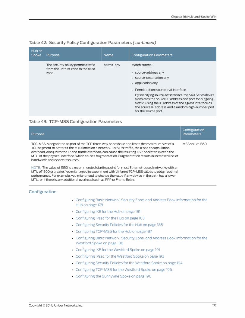
Table 42: Security Policy Configuration Parameters (continued)
Configuration ParametersNamePurposeHub orSpoke
Match criteria:
• source-address any
• source-destination any
• application any
• Permit action: source-nat interface
By specifying source-nat interface, the SRX Series devicetranslates the source IP address and port for outgoingtraffic, using the IP address of the egress interface asthe source IP address and a random high-number portfor the source port.
permit-anyThe security policy permits trafficfrom the untrust zone to the trustzone.
Table 43: TCP-MSS Configuration Parameters
ConfigurationParametersPurpose
MSS value: 1350TCC-MSS is negotiated as part of the TCP three-way handshake and limits the maximum size of aTCP segment to better fit the MTU limits on a network. For VPN traffic, the IPsec encapsulationoverhead, along with the IP and frame overhead, can cause the resulting ESP packet to exceed theMTU of the physical interface, which causes fragmentation. Fragmentation results in increased use ofbandwidth and device resources.
NOTE: The value of 1350 is a recommended starting point for most Ethernet-based networks with anMTU of 1500 or greater. You might need to experiment with different TCP-MSS values to obtain optimalperformance. For example, you might need to change the value if any device in the path has a lowerMTU, or if there is any additional overhead such as PPP or Frame Relay.
Configuration
• Configuring Basic Network, Security Zone, and Address Book Information for the
Hub on page 178
• Configuring IKE for the Hub on page 181
• Configuring IPsec for the Hub on page 183
• Configuring Security Policies for the Hub on page 185
• Configuring TCP-MSS for the Hub on page 187
• Configuring Basic Network, Security Zone, and Address Book Information for the
Westford Spoke on page 188
• Configuring IKE for the Westford Spoke on page 191
• Configuring IPsec for the Westford Spoke on page 193
• Configuring Security Policies for the Westford Spoke on page 194
• Configuring TCP-MSS for the Westford Spoke on page 196
• Configuring the Sunnyvale Spoke on page 196
177Copyright © 2014, Juniper Networks, Inc.
Chapter 16: Hub-and-Spoke VPN

Configuring Basic Network, Security Zone, and Address Book Information for theHub
CLI QuickConfiguration
To quickly configure this section of the example, copy the following commands, paste
them into a text file, remove any line breaks, change any details necessary to match your
network configuration, and then copy and paste the commands into the CLI at the [edit]
hierarchy level.
set interfaces ge-0/0/0 unit 0 family inet address 10.10.10.1/24set interfaces ge-0/0/3 unit 0 family inet address 1.1.1.2/30set interfaces st0 unit 0 family inet address 10.11.11.10/24set routing-options static route 0.0.0.0/0 next-hop 1.1.1.1set routing-options static route 192.168.168.0/24 next-hop 10.11.11.11set routing-options static route 192.168.178.0/24 next-hop 10.11.11.12set security zones security-zone untrust interfaces ge-0/0/3.0set security zones security-zone untrust host-inbound-traffic system-services ikeset security zones security-zone trust interfaces ge-0/0/0.0set security zones security-zone trust host-inbound-traffic system-services allset security zones security-zone vpn interfaces st0.0set security address-book book1 address local-net 10.10.10.0/24set security address-book book1 attach zone trustset security address-book book2 address sunnyvale-net 192.168.168.0/24set security address-book book2 address westford-net 192.168.178.0/24set security address-book book2 attach zone vpn
Step-by-StepProcedure
The following example requires you to navigate various levels in the configuration
hierarchy. For instructions on how to do that, see Using the CLI Editor in Configuration
Mode.
To configure basic network, security zone, and address book information for the hub:
1. Configure Ethernet interface information.
[edit]user@hub# set interfaces ge-0/0/0 unit 0 family inet address 10.10.10.1/24user@hub# set interfaces ge-0/0/3 unit 0 family inet address 1.1.1.2/30user@hub# set interfaces st0 unit 0 family inet address 10.11.11.10/24
2. Configure static route information.
[edit]user@hub# set routing-options static route 0.0.0.0/0 next-hop 1.1.1.1user@hub# set routing-options static route 192.168.168.0/24 next-hop 10.11.11.11user@hub# set routing-options static route 192.168.178.0/24 next-hop 10.11.11.12
3. Configure the untrust security zone.
[edit ]user@hub# set security zones security-zone untrust
4. Assign an interface to the untrust security zone.
[edit security zones security-zone untrust]user@hub# set interfaces ge-0/0/3.0
5. Specify allowed system services for the untrust security zone.
[edit security zones security-zone untrust]
Copyright © 2014, Juniper Networks, Inc.178
IPsec VPNs Feature Guide for Security Devices
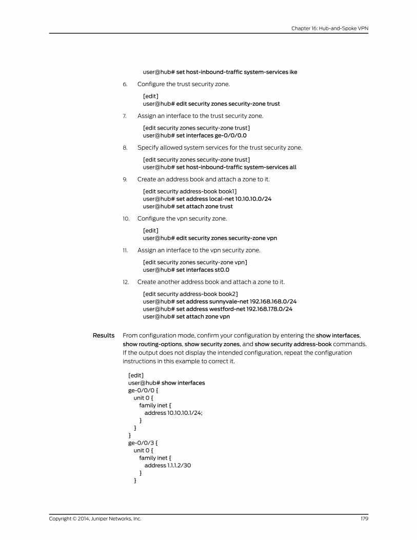
user@hub# set host-inbound-traffic system-services ike
6. Configure the trust security zone.
[edit]user@hub# edit security zones security-zone trust
7. Assign an interface to the trust security zone.
[edit security zones security-zone trust]user@hub# set interfaces ge-0/0/0.0
8. Specify allowed system services for the trust security zone.
[edit security zones security-zone trust]user@hub# set host-inbound-traffic system-services all
9. Create an address book and attach a zone to it.
[edit security address-book book1]user@hub# set address local-net 10.10.10.0/24user@hub# set attach zone trust
10. Configure the vpn security zone.
[edit]user@hub# edit security zones security-zone vpn
11. Assign an interface to the vpn security zone.
[edit security zones security-zone vpn]user@hub# set interfaces st0.0
12. Create another address book and attach a zone to it.
[edit security address-book book2]user@hub# set address sunnyvale-net 192.168.168.0/24user@hub# set address westford-net 192.168.178.0/24user@hub# set attach zone vpn
Results From configuration mode, confirm your configuration by entering the show interfaces,
show routing-options, show security zones, and show security address-book commands.
If the output does not display the intended configuration, repeat the configuration
instructions in this example to correct it.
[edit]user@hub# show interfacesge-0/0/0 {unit 0 {family inet {address 10.10.10.1/24;
}}
}ge-0/0/3 {unit 0 {family inet {address 1.1.1.2/30
}}
179Copyright © 2014, Juniper Networks, Inc.
Chapter 16: Hub-and-Spoke VPN
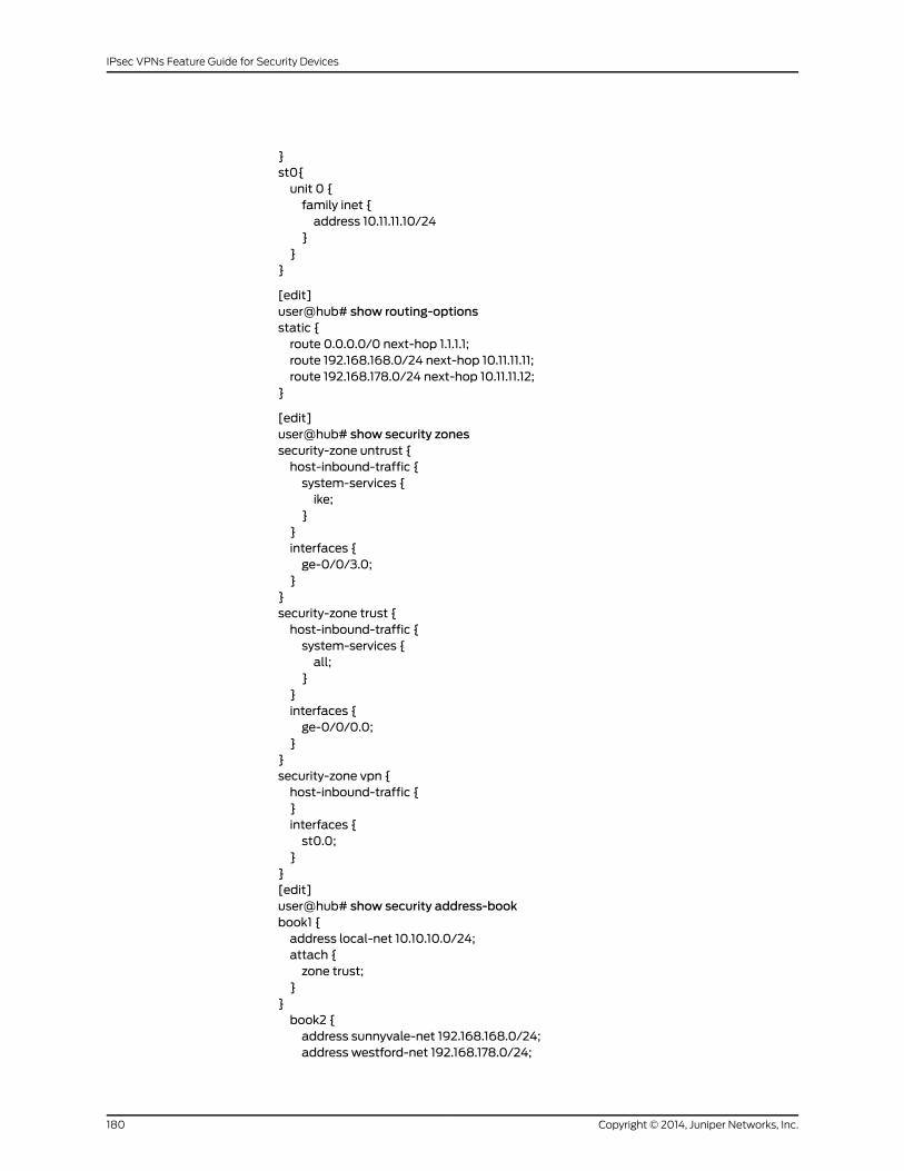
}st0{unit 0 {family inet {address 10.11.11.10/24
}}
}
[edit]user@hub# show routing-optionsstatic {route 0.0.0.0/0 next-hop 1.1.1.1;route 192.168.168.0/24 next-hop 10.11.11.11;route 192.168.178.0/24 next-hop 10.11.11.12;
}
[edit]user@hub# show security zonessecurity-zone untrust {host-inbound-traffic {system-services {ike;
}}interfaces {ge-0/0/3.0;
}}security-zone trust {host-inbound-traffic {system-services {all;
}}interfaces {ge-0/0/0.0;
}}security-zone vpn {host-inbound-traffic {}interfaces {st0.0;
}}[edit]user@hub# show security address-bookbook1 {address local-net 10.10.10.0/24;attach {zone trust;
}}book2 {address sunnyvale-net 192.168.168.0/24;address westford-net 192.168.178.0/24;
Copyright © 2014, Juniper Networks, Inc.180
IPsec VPNs Feature Guide for Security Devices

attach {zone vpn;
}}
If you are done configuring the device, enter commit from configuration mode.
Configuring IKE for the Hub
CLI QuickConfiguration
To quickly configure this section of the example, copy the following commands, paste
them into a text file, remove any line breaks, change any details necessary to match your
network configuration, and then copy and paste the commands into the CLI at the [edit]
hierarchy level.
set security ike proposal ike-phase1-proposal authentication-method pre-shared-keysset security ike proposal ike-phase1-proposal dh-group group2set security ike proposal ike-phase1-proposal authentication-algorithm sha1set security ike proposal ike-phase1-proposal encryption-algorithm aes-128-cbcset security ike policy ike-phase1-policymodemainset security ike policy ike-phase1-policy proposals ike-phase1-proposalset security ike policy ike-phase1-policy pre-shared-key ascii-text 395psksecr3tset security ike gateway gw-westford external-interface ge-0/0/3.0set security ike gateway gw-westford ike-policy ike-phase1-policyset security ike gateway gw-westford address 3.3.3.2set security ike gateway gw-sunnyvale external-interface ge-0/0/3.0set security ike gateway gw-sunnyvale ike-policy ike-phase1-policyset security ike gateway gw-sunnyvale address 2.2.2.2
Step-by-StepProcedure
The following example requires you to navigate various levels in the configuration
hierarchy. For instructions on how to do that, see Using the CLI Editor in Configuration
Mode.
To configure IKE for the hub:
1. Create the IKE Phase 1 proposal.
[edit security ike]user@hub# set proposal ike-phase1-proposal
2. Define the IKE proposal authentication method.
[edit security ike proposal ike-phase1-proposal]user@hub# set authentication-method pre-shared-keys
3. Define the IKE proposal Diffie-Hellman group.
[edit security ike proposal ike-phase1-proposal]user@hub# set dh-group group2
4. Define the IKE proposal authentication algorithm.
[edit security ike proposal ike-phase1-proposal]user@hub# set authentication-algorithm sha1
5. Define the IKE proposal encryption algorithm.
[edit security ike proposal ike-phase1-proposal]user@hub# set encryption-algorithm aes-128-cbc
181Copyright © 2014, Juniper Networks, Inc.
Chapter 16: Hub-and-Spoke VPN

6. Create an IKE Phase 1 policy.
[edit security ike]user@hub# set policy ike-phase1-policy
7. Set the IKE Phase 1 policy mode.
[edit security ike policy ike-phase1-policy]user@hub# setmodemain
8. Specify a reference to the IKE proposal.
[edit security ike policy ike-phase1-policy]user@hub# set proposals ike-phase1-proposal
9. Define the IKE Phase 1 policy authentication method.
[edit security ike policy ike-phase1-policy]user@hub# set pre-shared-key ascii-text 395psksecr3t
10. Create an IKE Phase 1 gateway and define its external interface.
[edit security ike]user@hub# set gateway gw-westford external-interface ge-0/0/3.0
11. Define the IKE Phase 1 policy reference.
[edit security ike]user@hub# set gateway gw-westford ike-policy ike-phase1-policy
12. Define the IKE Phase 1 gateway address.
[edit security ike]user@hub# set gateway gw-westford address 3.3.3.2
13. Create an IKE Phase 1 gateway and define its external interface.
[edit security ike]user@hub# set gateway gw-sunnyvale external-interface ge-0/0/3.0
14. Define the IKE Phase 1 policy reference.
[edit security ike gateway]user@hub# set gateway gw-sunnyvale ike-policy ike-phase1-policy
15. Define the IKE Phase 1 gateway address.
[edit security ike gateway]user@hub# set gateway gw-sunnyvale address 2.2.2.2
Results From configuration mode, confirm your configuration by entering the show security ike
command. If the output does not display the intended configuration, repeat the
configuration instructions in this example to correct it.
[edit]user@hub# show security ikeproposal ike-phase1-proposal {authentication-method pre-shared-keys;dh-group group2;authentication-algorithm sha1;encryption-algorithm aes-128-cbc;
}
Copyright © 2014, Juniper Networks, Inc.182
IPsec VPNs Feature Guide for Security Devices

policy ike-phase1-policy {modemain;proposals ike-phase1-proposal;pre-shared-key ascii-text "$9$9VMTp1RvWLdwYKMJDkmF3ylKM87Vb2oZjws5F"; ##SECRET-DATA
}gateway gw-sunnyvale {ike-policy ike-phase1-policy;address 2.2.2.2;external-interface ge-0/0/3.0;
}gateway gw-westford {ike-policy ike-phase1-policy;address 3.3.3.2;external-interface ge-0/0/3.0;
}
If you are done configuring the device, enter commit from configuration mode.
Configuring IPsec for the Hub
CLI QuickConfiguration
To quickly configure this section of the example, copy the following commands, paste
them into a text file, remove any line breaks, change any details necessary to match your
network configuration, and then copy and paste the commands into the CLI at the [edit]
hierarchy level.
set security ipsec proposal ipsec-phase2-proposal protocol espsetsecurity ipsecproposal ipsec-phase2-proposalauthentication-algorithmhmac-sha1-96set security ipsec proposal ipsec-phase2-proposal encryption-algorithm aes-128-cbcset security ipsec policy ipsec-phase2-policy proposals ipsec-phase2-proposalset security ipsec policy ipsec-phase2-policy perfect-forward-secrecy keys group2set security ipsec vpn vpn-westford ike gateway gw-westfordset security ipsec vpn vpn-westford ike ipsec-policy ipsec-phase2-policyset security ipsec vpn vpn-westford bind-interface st0.0set security ipsec vpn vpn-sunnyvale ike gateway gw-sunnyvaleset security ipsec vpn vpn-sunnyvale ike ipsec-policy ipsec-phase2-policyset security ipsec vpn vpn-sunnyvale bind-interface st0.0set interfaces st0 unit 0multipointset interfaces st0 unit 0 family inet next-hop-tunnel 10.11.11.11 ipsec-vpn vpn-sunnyvale
Step-by-StepProcedure
The following example requires you to navigate various levels in the configuration
hierarchy. For instructions on how to do that, see Using the CLI Editor in Configuration
Mode.
To configure IPsec for the hub:
1. Create an IPsec Phase 2 proposal.
[edit]user@hub# set security ipsec proposal ipsec-phase2-proposal
2. Specify the IPsec Phase 2 proposal protocol.
[edit security ipsec proposal ipsec-phase2-proposal]user@hub# set protocol esp
183Copyright © 2014, Juniper Networks, Inc.
Chapter 16: Hub-and-Spoke VPN

3. Specify the IPsec Phase 2 proposal authentication algorithm.
[edit security ipsec proposal ipsec-phase2-proposal]user@hub# set authentication-algorithm hmac-sha1-96
4. Specify the IPsec Phase 2 proposal encryption algorithm.
[edit security ipsec proposal ipsec-phase2-proposal]user@hub# set encryption-algorithm aes-128-cbc
5. Create the IPsec Phase 2 policy.
[edit security ipsec]user@hub# set policy ipsec-phase2-policy
6. Specify the IPsec Phase 2 proposal reference.
[edit security ipsec policy ipsec-phase2-policy]user@hub# set proposals ipsec-phase2-proposal
7. Specify IPsec Phase 2 PFS to use Diffie-Hellman group 2.
[edit security ipsec policy ipsec-phase2-policy]user@host# set perfect-forward-secrecy keys group2
8. Specify the IKE gateways.
[edit security ipsec]user@hub# set vpn vpn-westford ike gateway gw-westforduser@hub# set vpn vpn-sunnyvale ike gateway gw-sunnyvale
9. Specify the IPsec Phase 2 policies.
[edit security ipsec]user@hub# set vpn vpn-westford ike ipsec-policy ipsec-phase2-policyuser@hub# set vpn vpn-sunnyvale ike ipsec-policy ipsec-phase2-policy
10. Specify the interface to bind.
[edit security ipsec]user@hub# set vpn vpn-westford bind-interface st0.0user@hub# set vpn vpn-sunnyvale bind-interface st0.0
11. Configure the st0 interface as multipoint.
[edit]user@hub# set interfaces st0 unit 0multipoint
12. Add static NHTB table entries for the Sunnyvale and Westford offices.
[edit]user@hub# set interfaces st0unit 0 family inet next-hop-tunnel 10.11.11.11 ipsec-vpnvpn-sunnyvale
user@hub# set interfacesst0unit0 family inetnext-hop-tunnel 10.11.11.12 ipsec-vpnvpn-westford
Results From configuration mode, confirm your configuration by entering the show security ipsec
command. If the output does not display the intended configuration, repeat the
configuration instructions in this example to correct it.
[edit]user@hub# show security ipsec
Copyright © 2014, Juniper Networks, Inc.184
IPsec VPNs Feature Guide for Security Devices
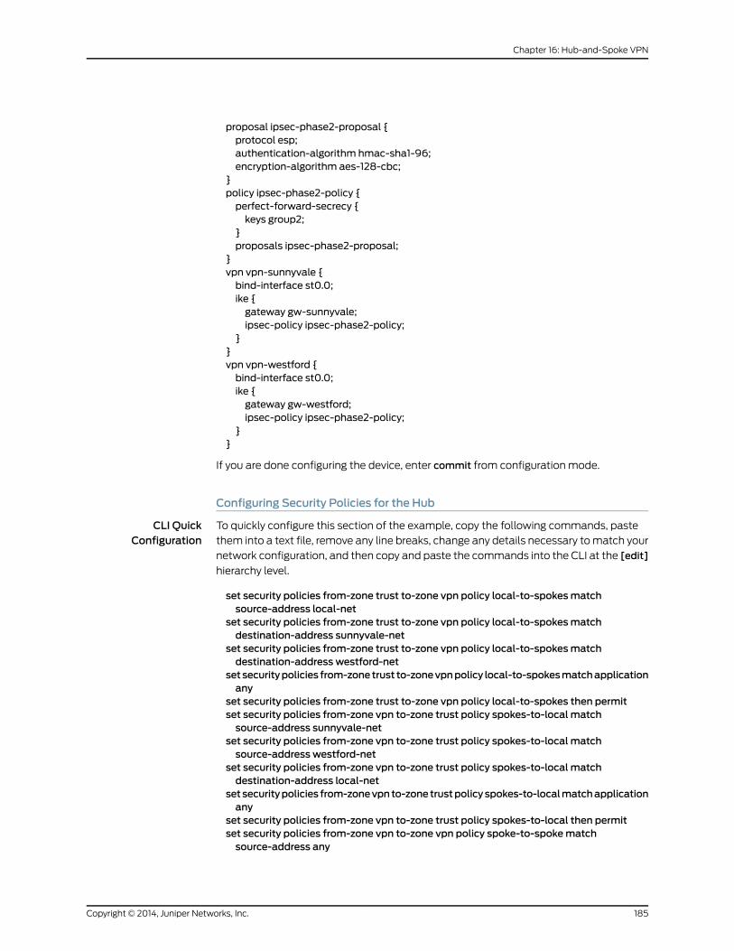
proposal ipsec-phase2-proposal {protocol esp;authentication-algorithm hmac-sha1-96;encryption-algorithm aes-128-cbc;
}policy ipsec-phase2-policy {perfect-forward-secrecy {keys group2;
}proposals ipsec-phase2-proposal;
}vpn vpn-sunnyvale {bind-interface st0.0;ike {gateway gw-sunnyvale;ipsec-policy ipsec-phase2-policy;
}}vpn vpn-westford {bind-interface st0.0;ike {gateway gw-westford;ipsec-policy ipsec-phase2-policy;
}}
If you are done configuring the device, enter commit from configuration mode.
Configuring Security Policies for the Hub
CLI QuickConfiguration
To quickly configure this section of the example, copy the following commands, paste
them into a text file, remove any line breaks, change any details necessary to match your
network configuration, and then copy and paste the commands into the CLI at the [edit]
hierarchy level.
set security policies from-zone trust to-zone vpn policy local-to-spokesmatchsource-address local-net
set security policies from-zone trust to-zone vpn policy local-to-spokesmatchdestination-address sunnyvale-net
set security policies from-zone trust to-zone vpn policy local-to-spokesmatchdestination-address westford-net
setsecuritypolicies from-zonetrust to-zonevpnpolicy local-to-spokesmatchapplicationany
set security policies from-zone trust to-zone vpn policy local-to-spokes then permitset security policies from-zone vpn to-zone trust policy spokes-to-local matchsource-address sunnyvale-net
set security policies from-zone vpn to-zone trust policy spokes-to-local matchsource-address westford-net
set security policies from-zone vpn to-zone trust policy spokes-to-local matchdestination-address local-net
setsecuritypolicies from-zonevpnto-zonetrustpolicyspokes-to-localmatchapplicationany
set security policies from-zone vpn to-zone trust policy spokes-to-local then permitset security policies from-zone vpn to-zone vpn policy spoke-to-spokematchsource-address any
185Copyright © 2014, Juniper Networks, Inc.
Chapter 16: Hub-and-Spoke VPN
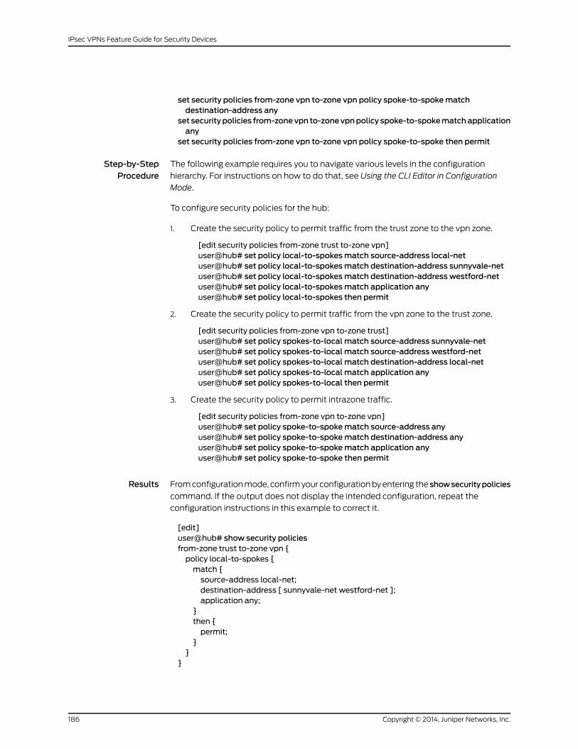
set security policies from-zone vpn to-zone vpn policy spoke-to-spokematchdestination-address any
set securitypolicies from-zonevpn to-zonevpnpolicy spoke-to-spokematchapplicationany
set security policies from-zone vpn to-zone vpn policy spoke-to-spoke then permit
Step-by-StepProcedure
The following example requires you to navigate various levels in the configuration
hierarchy. For instructions on how to do that, see Using the CLI Editor in Configuration
Mode.
To configure security policies for the hub:
1. Create the security policy to permit traffic from the trust zone to the vpn zone.
[edit security policies from-zone trust to-zone vpn]user@hub# set policy local-to-spokesmatch source-address local-netuser@hub# set policy local-to-spokesmatch destination-address sunnyvale-netuser@hub# set policy local-to-spokesmatch destination-address westford-netuser@hub# set policy local-to-spokesmatch application anyuser@hub# set policy local-to-spokes then permit
2. Create the security policy to permit traffic from the vpn zone to the trust zone.
[edit security policies from-zone vpn to-zone trust]user@hub# set policy spokes-to-local match source-address sunnyvale-netuser@hub# set policy spokes-to-local match source-address westford-netuser@hub# set policy spokes-to-local match destination-address local-netuser@hub# set policy spokes-to-local match application anyuser@hub# set policy spokes-to-local then permit
3. Create the security policy to permit intrazone traffic.
[edit security policies from-zone vpn to-zone vpn]user@hub# set policy spoke-to-spokematch source-address anyuser@hub# set policy spoke-to-spokematch destination-address anyuser@hub# set policy spoke-to-spokematch application anyuser@hub# set policy spoke-to-spoke then permit
Results From configuration mode, confirm your configuration by entering the showsecuritypolicies
command. If the output does not display the intended configuration, repeat the
configuration instructions in this example to correct it.
[edit]user@hub# show security policiesfrom-zone trust to-zone vpn {policy local-to-spokes {match {source-address local-net;destination-address [ sunnyvale-net westford-net ];application any;
}then {permit;
}}
}
Copyright © 2014, Juniper Networks, Inc.186
IPsec VPNs Feature Guide for Security Devices

from-zone vpn to-zone trust {policy spokes-to-local {match {source-address [ sunnyvale-net westford-net ];destination-address local-net;application any;
}then {permit;
}}
}from-zone vpn to-zone vpn {policy spoke-to-spoke {match {source-address any;destination-address any;application any;
}then {permit;
}}
}
If you are done configuring the device, enter commit from configuration mode.
Configuring TCP-MSS for the Hub
CLI QuickConfiguration
To quickly configure this section of the example, copy the following command, paste it
into a text file, remove any line breaks, change any details necessary to match your
network configuration, and then copy and paste the command into the CLI at the [edit]
hierarchy level.
set security flow tcp-mss ipsec-vpnmss 1350
Step-by-StepProcedure
To configure TCP-MSS information for the hub:
Configure TCP-MSS information.1.
[edit]user@hub# set security flow tcp-mss ipsec-vpnmss 1350
Results From configuration mode, confirm your configuration by entering the show security flow
command. If the output does not display the intended configuration, repeat the
configuration instructions in this example to correct it.
[edit]user@hub# show security flowtcp-mss {ipsec-vpn {mss 1350;
}}
187Copyright © 2014, Juniper Networks, Inc.
Chapter 16: Hub-and-Spoke VPN

If you are done configuring the device, enter commit from configuration mode.
Configuring Basic Network, Security Zone, and Address Book Information for theWestford Spoke
CLI QuickConfiguration
To quickly configure this section of the example, copy the following commands, paste
them into a text file, remove any line breaks, change any details necessary to match your
network configuration, and then copy and paste the commands into the CLI at the [edit]
hierarchy level.
set interfaces ge-0/0/0 unit 0 family inet address 3.3.3.2/30set interfaces ge-0/0/3 unit 0 family inet address 192.168.178.1/24set interfaces st0 unit 0 family inet address 10.11.11.12/24set routing-options static route 0.0.0.0/0 next-hop 3.1.1.1set routing-options static route 10.10.10.0/24 next-hop 10.11.11.10set routing-options static route 192.168.168.0/24 next-hop 10.11.11.10set security zones security-zone untrust interfaces ge-0/0/0.0set security zones security-zone untrust host-inbound-traffic system-services ikeset security zones security-zone trust interfaces ge-0/0/3.0set security zones security-zone trust host-inbound-traffic system-services allset security zones security-zone vpn interfaces st0.0set security address-book book1 address local-net 192.168.178.0/24set security address-book book1 attach zone trustset security address-book book2 address corp-net 10.10.10.0/24set security address-book book2 address sunnyvale-net 192.168.168.0/24set security address-book book2 attach zone vpn
Step-by-StepProcedure
The following example requires you to navigate various levels in the configuration
hierarchy. For instructions on how to do that, see Using the CLI Editor in Configuration
Mode.
To configure basic network, security zone, and address book information for the Westford
spoke:
1. Configure Ethernet interface information.
[edit]user@spoke# set interfaces ge-0/0/0 unit 0 family inet address 3.3.3.2/30user@spoke# set interfaces ge-0/0/3 unit 0 family inet address 192.168.178.1/24user@spoke# set interfaces st0 unit 0 family inet address 10.11.11.12/24
2. Configure static route information.
[edit]user@spoke# set routing-options static route 0.0.0.0/0 next-hop 3.1.1.1user@spoke# set routing-options static route 10.10.10.0/24 next-hop 10.11.11.10user@spoke# set routing-options static route 192.168.168.0/24 next-hop 10.11.11.10
3. Configure the untrust security zone.
[edit]user@spoke# set security zones security-zone untrust
4. Assign an interface to the security zone.
[edit security zones security-zone untrust]user@spoke# set interfaces ge-0/0/0.0
Copyright © 2014, Juniper Networks, Inc.188
IPsec VPNs Feature Guide for Security Devices
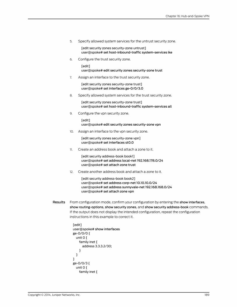
5. Specify allowed system services for the untrust security zone.
[edit security zones security-zone untrust]user@spoke# set host-inbound-traffic system-services ike
6. Configure the trust security zone.
[edit]user@spoke# edit security zones security-zone trust
7. Assign an interface to the trust security zone.
[edit security zones security-zone trust]user@spoke# set interfaces ge-0/0/3.0
8. Specify allowed system services for the trust security zone.
[edit security zones security-zone trust]user@spoke# set host-inbound-traffic system-services all
9. Configure the vpn security zone.
[edit]user@spoke# edit security zones security-zone vpn
10. Assign an interface to the vpn security zone.
[edit security zones security-zone vpn]user@spoke# set interfaces st0.0
11. Create an address book and attach a zone to it.
[edit security address-book book1]user@spoke# set address local-net 192.168.178.0/24user@spoke# set attach zone trust
12. Create another address book and attach a zone to it.
[edit security address-book book2]user@spoke# set address corp-net 10.10.10.0/24user@spoke# set address sunnyvale-net 192.168.168.0/24user@spoke# set attach zone vpn
Results From configuration mode, confirm your configuration by entering the show interfaces,
show routing-options, show security zones, and show security address-book commands.
If the output does not display the intended configuration, repeat the configuration
instructions in this example to correct it.
[edit]user@spoke# show interfacesge-0/0/0 {unit 0 {family inet {address 3.3.3.2/30;
}}
}ge-0/0/3 {unit 0 {family inet {
189Copyright © 2014, Juniper Networks, Inc.
Chapter 16: Hub-and-Spoke VPN
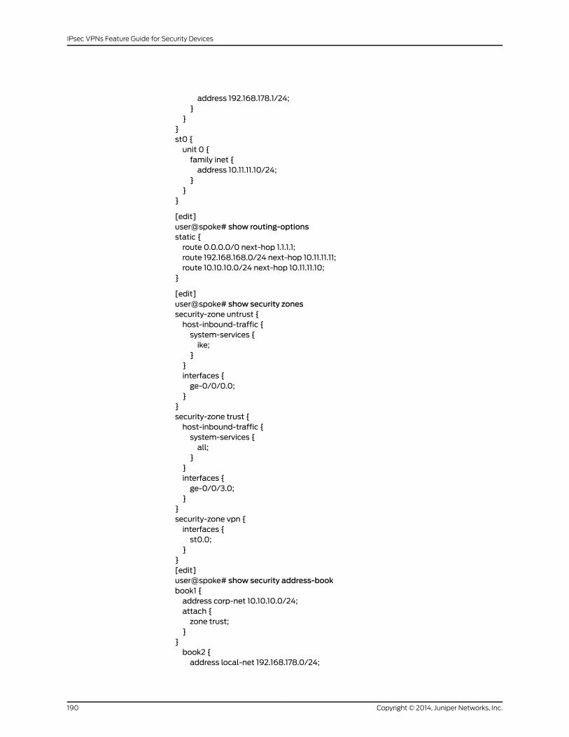
address 192.168.178.1/24;}
}}st0 {unit 0 {family inet {address 10.11.11.10/24;
}}
}
[edit]user@spoke# show routing-optionsstatic {route 0.0.0.0/0 next-hop 1.1.1.1;route 192.168.168.0/24 next-hop 10.11.11.11;route 10.10.10.0/24 next-hop 10.11.11.10;
}
[edit]user@spoke# show security zonessecurity-zone untrust {host-inbound-traffic {system-services {ike;
}}interfaces {ge-0/0/0.0;
}}security-zone trust {host-inbound-traffic {system-services {all;
}}interfaces {ge-0/0/3.0;
}}security-zone vpn {interfaces {st0.0;
}}[edit]user@spoke# show security address-bookbook1 {address corp-net 10.10.10.0/24;attach {zone trust;
}}book2 {address local-net 192.168.178.0/24;
Copyright © 2014, Juniper Networks, Inc.190
IPsec VPNs Feature Guide for Security Devices

address sunnyvale-net 192.168.168.0/24;attach {zone vpn;
}}
If you are done configuring the device, enter commit from configuration mode.
Configuring IKE for theWestford Spoke
CLI QuickConfiguration
To quickly configure this section of the example, copy the following commands, paste
them into a text file, remove any line breaks, change any details necessary to match your
network configuration, and then copy and paste the commands into the CLI at the [edit]
hierarchy level.
set security ike proposal ike-phase1-proposal authentication-method pre-shared-keysset security ike proposal ike-phase1-proposal dh-group group2set security ike proposal ike-phase1-proposal authentication-algorithm sha1set security ike proposal ike-phase1-proposal encryption-algorithm aes-128-cbcset security ike policy ike-phase1-policymodemainset security ike policy ike-phase1-policy proposals ike-phase1-proposalset security ike policy ike-phase1-policy pre-shared-key ascii-text 395psksecr3tset security ike gateway gw-corporate external-interface ge-0/0/0.0set security ike gateway gw-corporate ike-policy ike-phase1-policyset security ike gateway gw-corporate address 1.1.1.2
Step-by-StepProcedure
The following example requires you to navigate various levels in the configuration
hierarchy. For instructions on how to do that, see Using the CLI Editor in Configuration
Mode.
To configure IKE for the Westford spoke:
1. Create the IKE Phase 1 proposal.
[edit security ike]user@spoke# set proposal ike-phase1-proposal
2. Define the IKE proposal authentication method.
[edit security ike proposal ike-phase1-proposal]user@spoke# set authentication-method pre-shared-keys
3. Define the IKE proposal Diffie-Hellman group.
[edit security ike proposal ike-phase1-proposal]user@spoke# set dh-group group2
4. Define the IKE proposal authentication algorithm.
[edit security ike proposal ike-phase1-proposal]user@spoke# set authentication-algorithm sha1
5. Define the IKE proposal encryption algorithm.
[edit security ike proposal ike-phase1-proposal]user@spoke# set encryption-algorithm aes-128-cbc
6. Create an IKE Phase 1 policy.
191Copyright © 2014, Juniper Networks, Inc.
Chapter 16: Hub-and-Spoke VPN
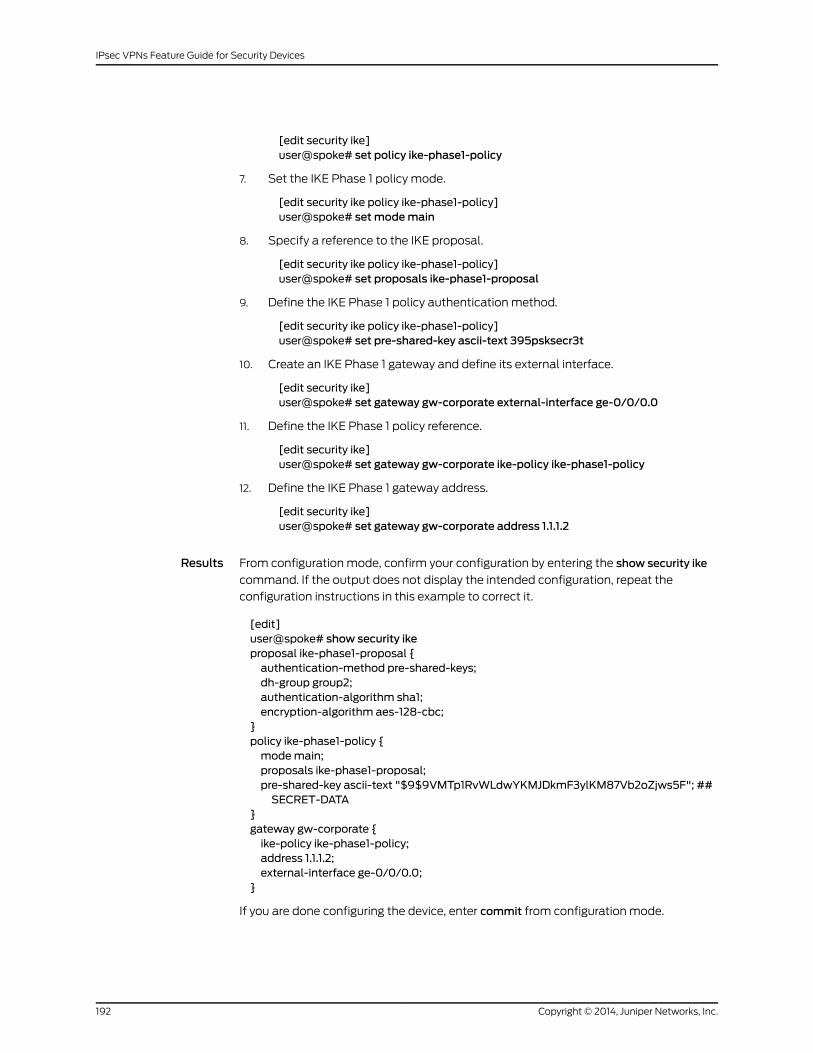
[edit security ike]user@spoke# set policy ike-phase1-policy
7. Set the IKE Phase 1 policy mode.
[edit security ike policy ike-phase1-policy]user@spoke# setmodemain
8. Specify a reference to the IKE proposal.
[edit security ike policy ike-phase1-policy]user@spoke# set proposals ike-phase1-proposal
9. Define the IKE Phase 1 policy authentication method.
[edit security ike policy ike-phase1-policy]user@spoke# set pre-shared-key ascii-text 395psksecr3t
10. Create an IKE Phase 1 gateway and define its external interface.
[edit security ike]user@spoke# set gateway gw-corporate external-interface ge-0/0/0.0
11. Define the IKE Phase 1 policy reference.
[edit security ike]user@spoke# set gateway gw-corporate ike-policy ike-phase1-policy
12. Define the IKE Phase 1 gateway address.
[edit security ike]user@spoke# set gateway gw-corporate address 1.1.1.2
Results From configuration mode, confirm your configuration by entering the show security ike
command. If the output does not display the intended configuration, repeat the
configuration instructions in this example to correct it.
[edit]user@spoke# show security ikeproposal ike-phase1-proposal {authentication-method pre-shared-keys;dh-group group2;authentication-algorithm sha1;encryption-algorithm aes-128-cbc;
}policy ike-phase1-policy {modemain;proposals ike-phase1-proposal;pre-shared-key ascii-text "$9$9VMTp1RvWLdwYKMJDkmF3ylKM87Vb2oZjws5F"; ##SECRET-DATA
}gateway gw-corporate {ike-policy ike-phase1-policy;address 1.1.1.2;external-interface ge-0/0/0.0;
}
If you are done configuring the device, enter commit from configuration mode.
Copyright © 2014, Juniper Networks, Inc.192
IPsec VPNs Feature Guide for Security Devices
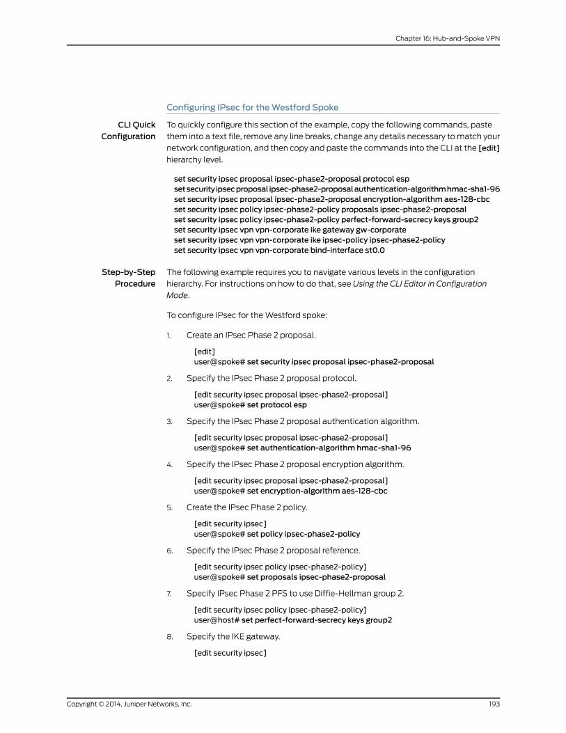
Configuring IPsec for theWestford Spoke
CLI QuickConfiguration
To quickly configure this section of the example, copy the following commands, paste
them into a text file, remove any line breaks, change any details necessary to match your
network configuration, and then copy and paste the commands into the CLI at the [edit]
hierarchy level.
set security ipsec proposal ipsec-phase2-proposal protocol espsetsecurity ipsecproposal ipsec-phase2-proposalauthentication-algorithmhmac-sha1-96set security ipsec proposal ipsec-phase2-proposal encryption-algorithm aes-128-cbcset security ipsec policy ipsec-phase2-policy proposals ipsec-phase2-proposalset security ipsec policy ipsec-phase2-policy perfect-forward-secrecy keys group2set security ipsec vpn vpn-corporate ike gateway gw-corporateset security ipsec vpn vpn-corporate ike ipsec-policy ipsec-phase2-policyset security ipsec vpn vpn-corporate bind-interface st0.0
Step-by-StepProcedure
The following example requires you to navigate various levels in the configuration
hierarchy. For instructions on how to do that, see Using the CLI Editor in Configuration
Mode.
To configure IPsec for the Westford spoke:
1. Create an IPsec Phase 2 proposal.
[edit]user@spoke# set security ipsec proposal ipsec-phase2-proposal
2. Specify the IPsec Phase 2 proposal protocol.
[edit security ipsec proposal ipsec-phase2-proposal]user@spoke# set protocol esp
3. Specify the IPsec Phase 2 proposal authentication algorithm.
[edit security ipsec proposal ipsec-phase2-proposal]user@spoke# set authentication-algorithm hmac-sha1-96
4. Specify the IPsec Phase 2 proposal encryption algorithm.
[edit security ipsec proposal ipsec-phase2-proposal]user@spoke# set encryption-algorithm aes-128-cbc
5. Create the IPsec Phase 2 policy.
[edit security ipsec]user@spoke# set policy ipsec-phase2-policy
6. Specify the IPsec Phase 2 proposal reference.
[edit security ipsec policy ipsec-phase2-policy]user@spoke# set proposals ipsec-phase2-proposal
7. Specify IPsec Phase 2 PFS to use Diffie-Hellman group 2.
[edit security ipsec policy ipsec-phase2-policy]user@host# set perfect-forward-secrecy keys group2
8. Specify the IKE gateway.
[edit security ipsec]
193Copyright © 2014, Juniper Networks, Inc.
Chapter 16: Hub-and-Spoke VPN

user@spoke# set vpn vpn-corporate ike gateway gw-corporate
9. Specify the IPsec Phase 2 policy.
[edit security ipsec]user@spoke# set vpn vpn-corporate ike ipsec-policy ipsec-phase2-policy
10. Specify the interface to bind.
[edit security ipsec]user@spoke# set vpn vpn-corporate bind-interface st0.0
Results From configuration mode, confirm your configuration by entering the show security ipsec
command. If the output does not display the intended configuration, repeat the
configuration instructions in this example to correct it.
[edit]user@spoke# show security ipsecproposal ipsec-phase2-proposal {protocol esp;authentication-algorithm hmac-sha1-96;encryption-algorithm aes-128-cbc;
}policy ipsec-phase2-policy {perfect-forward-secrecy {keys group2;
}proposals ipsec-phase2-proposal;
}vpn vpn-corporate {bind-interface st0.0;ike {gateway gw-corporate;ipsec-policy ipsec-phase2-policy;
}}
If you are done configuring the device, enter commit from configuration mode.
Configuring Security Policies for theWestford Spoke
CLI QuickConfiguration
To quickly configure this section of the example, copy the following commands, paste
them into a text file, remove any line breaks, change any details necessary to match your
network configuration, and then copy and paste the commands into the CLI at the [edit]
hierarchy level.
setsecuritypolicies from-zonetrust to-zonevpnpolicy to-corporatematchsource-addresslocal-net
set security policies from-zone trust to-zone vpn policy to-corporatematchdestination-address corp-net
set security policies from-zone trust to-zone vpn policy to-corporatematchdestination-address sunnyvale-net
set security policies from-zone trust to-zone vpn policy to-corporate application anyset security policies from-zone trust to-zone vpn policy to-corporate then permitset security policies from-zone vpn to-zone trust policy from-corporatematchsource-address corp-net
Copyright © 2014, Juniper Networks, Inc.194
IPsec VPNs Feature Guide for Security Devices

set security policies from-zone vpn to-zone trust policy from-corporatematchsource-address sunnyvale-net
set security policies from-zone vpn to-zone trust policy from-corporatematchdestination-address local-net
set security policies from-zone vpn to-zone trust policy from-corporate application anyset security policies from-zone vpn to-zone trust policy from-corporate then permit
Step-by-StepProcedure
The following example requires you to navigate various levels in the configuration
hierarchy. For instructions on how to do that, see Using the CLI Editor in Configuration
Mode.
To configure security policies for the Westford spoke:
1. Create the security policy to permit traffic from the trust zone to the vpn zone.
[edit security policies from-zone trust to-zone vpn]user@spoke# set policy to-corpmatch source-address local-netuser@spoke# set policy to-corpmatch destination-address corp-netuser@spoke# set policy to-corpmatch destination-address sunnyvale-netuser@spoke# set policy to-corpmatch application anyuser@spoke# set policy to-corp then permit
2. Create the security policy to permit traffic from the vpn zone to the trust zone.
[edit security policies from-zone vpn to-zone trust]user@spoke# set policy spokes-to-local match source-address corp-netuser@spoke# set policy spokes-to-local match source-address sunnyvale-netuser@spoke# set policy spokes-to-local match destination-address local-netuser@spoke# set policy spokes-to-local match application anyuser@spoke# set policy spokes-to-local then permit
Results From configuration mode, confirm your configuration by entering the showsecuritypolicies
command. If the output does not display the intended configuration, repeat the
configuration instructions in this example to correct it.
[edit]user@spoke# show security policiesfrom-zone trust to-zone vpn {policy to-corp {match {source-address local-net;destination-address [ sunnyvale-net westford-net ];application any;
}then {permit;
}}
}from-zone vpn to-zone trust {policy spokes-to-local {match {source-address [ sunnyvale-net westford-net ];destination-address local-net;application any;
}
195Copyright © 2014, Juniper Networks, Inc.
Chapter 16: Hub-and-Spoke VPN
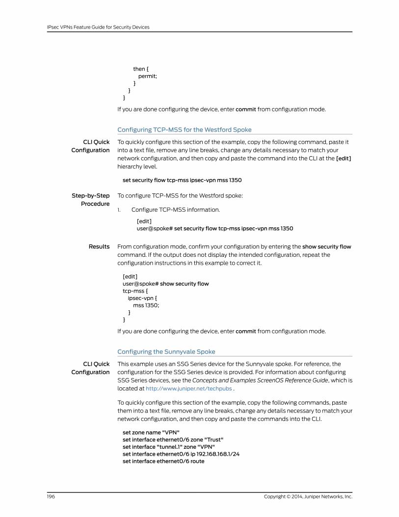
then {permit;
}}
}
If you are done configuring the device, enter commit from configuration mode.
Configuring TCP-MSS for theWestford Spoke
CLI QuickConfiguration
To quickly configure this section of the example, copy the following command, paste it
into a text file, remove any line breaks, change any details necessary to match your
network configuration, and then copy and paste the command into the CLI at the [edit]
hierarchy level.
set security flow tcp-mss ipsec-vpnmss 1350
Step-by-StepProcedure
To configure TCP-MSS for the Westford spoke:
Configure TCP-MSS information.1.
[edit]user@spoke# set security flow tcp-mss ipsec-vpnmss 1350
Results From configuration mode, confirm your configuration by entering the show security flow
command. If the output does not display the intended configuration, repeat the
configuration instructions in this example to correct it.
[edit]user@spoke# show security flowtcp-mss {ipsec-vpn {mss 1350;
}}
If you are done configuring the device, enter commit from configuration mode.
Configuring the Sunnyvale Spoke
CLI QuickConfiguration
This example uses an SSG Series device for the Sunnyvale spoke. For reference, the
configuration for the SSG Series device is provided. For information about configuring
SSG Series devices, see the Concepts and Examples ScreenOS Reference Guide, which is
located at http://www.juniper.net/techpubs .
To quickly configure this section of the example, copy the following commands, paste
them into a text file, remove any line breaks, change any details necessary to match your
network configuration, and then copy and paste the commands into the CLI.
set zone name "VPN"set interface ethernet0/6 zone "Trust"set interface "tunnel.1" zone "VPN"set interface ethernet0/6 ip 192.168.168.1/24set interface ethernet0/6 route
Copyright © 2014, Juniper Networks, Inc.196
IPsec VPNs Feature Guide for Security Devices

set interface ethernet0/0 ip 2.2.2.2/30set interface ethernet0/0 routeset interface tunnel.1 ip 10.11.11.11/24set flow tcp-mss 1350set address "Trust" "sunnyvale-net" 192.168.168.0 255.255.255.0set address "VPN" "corp-net" 10.10.10.0 255.255.255.0set address "VPN" "westford-net" 192.168.178.0 255.255.255.0set ike gateway "corp-ike" address 1.1.1.2 Main outgoing-interface ethernet0/0 preshare"395psksecr3t" sec-level standard
set vpn corp-vpnmonitor optimized rekeyset vpn "corp-vpn" bind interface tunnel.1set vpn "corp-vpn" gateway "corp-ike" replay tunnel idletime 0 sec-level standardset policy id 1 from "Trust" to "Untrust" "ANY" "ANY" "ANY" nat src permitset policy id 2 from "Trust" to "VPN" "sunnyvale-net" "corp-net" "ANY" permitset policy id 2exitset dst-address "westford-net"exitset policy id 3 from "VPN" to "Trust" "corp-net" "sunnyvale-net" "ANY" permitset policy id 3set src-address "westford-net"exitset route 10.10.10.0/24 interface tunnel.1set route 192.168.178.0/24 interface tunnel.1set route 0.0.0.0/0 interface ethernet0/0 gateway 2.2.2.1
Verification
To confirm that the configuration is working properly, perform these tasks:
• Verifying the IKE Phase 1 Status on page 197
• Verifying the IPsec Phase 2 Status on page 199
• Verifying Next-Hop Tunnel Bindings on page 200
• Verifying Static Routes for Remote Peer Local LANs on page 201
• Reviewing Statistics and Errors for an IPsec Security Association on page 201
• Testing Traffic Flow Across the VPN on page 202
Verifying the IKE Phase 1 Status
Purpose Verify the IKE Phase 1 status.
Action NOTE: Before starting the verification process, you need to send traffic froma host in the 10.10.10/24 network to a host in the 192.168.168/24 and192.168.178/24 networks to bring the tunnels up. For route-based VPNs, youcan send traffic initiated from the SRX Series device through the tunnel. Werecommend that when testing IPsec tunnels, you send test traffic from aseparate device on one side of the VPN to a second device on the other sideof the VPN. For example, initiate a ping from 10.10.10.10 to 192.168.168.10.
197Copyright © 2014, Juniper Networks, Inc.
Chapter 16: Hub-and-Spoke VPN
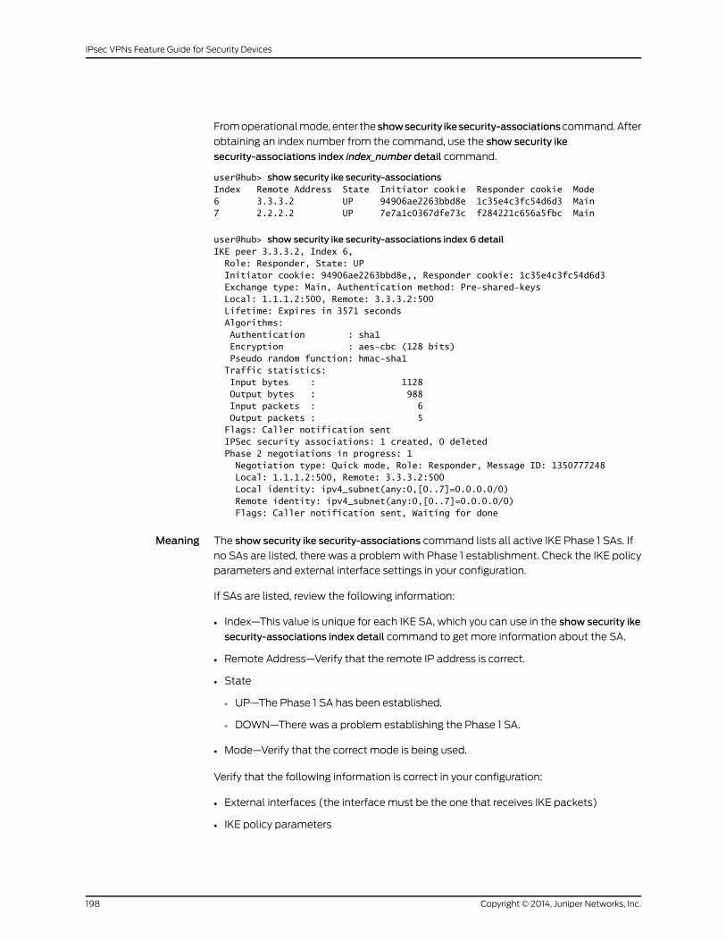
From operational mode, enter the showsecurity ikesecurity-associationscommand. After
obtaining an index number from the command, use the show security ike
security-associations index index_number detail command.
user@hub> show security ike security-associationsIndex Remote Address State Initiator cookie Responder cookie Mode6 3.3.3.2 UP 94906ae2263bbd8e 1c35e4c3fc54d6d3 Main7 2.2.2.2 UP 7e7a1c0367dfe73c f284221c656a5fbc Main
user@hub> show security ike security-associations index 6 detailIKE peer 3.3.3.2, Index 6, Role: Responder, State: UP Initiator cookie: 94906ae2263bbd8e,, Responder cookie: 1c35e4c3fc54d6d3 Exchange type: Main, Authentication method: Pre-shared-keys Local: 1.1.1.2:500, Remote: 3.3.3.2:500 Lifetime: Expires in 3571 seconds Algorithms: Authentication : sha1 Encryption : aes-cbc (128 bits) Pseudo random function: hmac-sha1 Traffic statistics: Input bytes : 1128 Output bytes : 988 Input packets : 6 Output packets : 5 Flags: Caller notification sent IPSec security associations: 1 created, 0 deleted Phase 2 negotiations in progress: 1 Negotiation type: Quick mode, Role: Responder, Message ID: 1350777248 Local: 1.1.1.2:500, Remote: 3.3.3.2:500 Local identity: ipv4_subnet(any:0,[0..7]=0.0.0.0/0) Remote identity: ipv4_subnet(any:0,[0..7]=0.0.0.0/0) Flags: Caller notification sent, Waiting for done
Meaning The show security ike security-associations command lists all active IKE Phase 1 SAs. If
no SAs are listed, there was a problem with Phase 1 establishment. Check the IKE policy
parameters and external interface settings in your configuration.
If SAs are listed, review the following information:
• Index—This value is unique for each IKE SA, which you can use in the show security ike
security-associations index detail command to get more information about the SA.
• Remote Address—Verify that the remote IP address is correct.
• State
• UP—The Phase 1 SA has been established.
• DOWN—There was a problem establishing the Phase 1 SA.
• Mode—Verify that the correct mode is being used.
Verify that the following information is correct in your configuration:
• External interfaces (the interface must be the one that receives IKE packets)
• IKE policy parameters
Copyright © 2014, Juniper Networks, Inc.198
IPsec VPNs Feature Guide for Security Devices
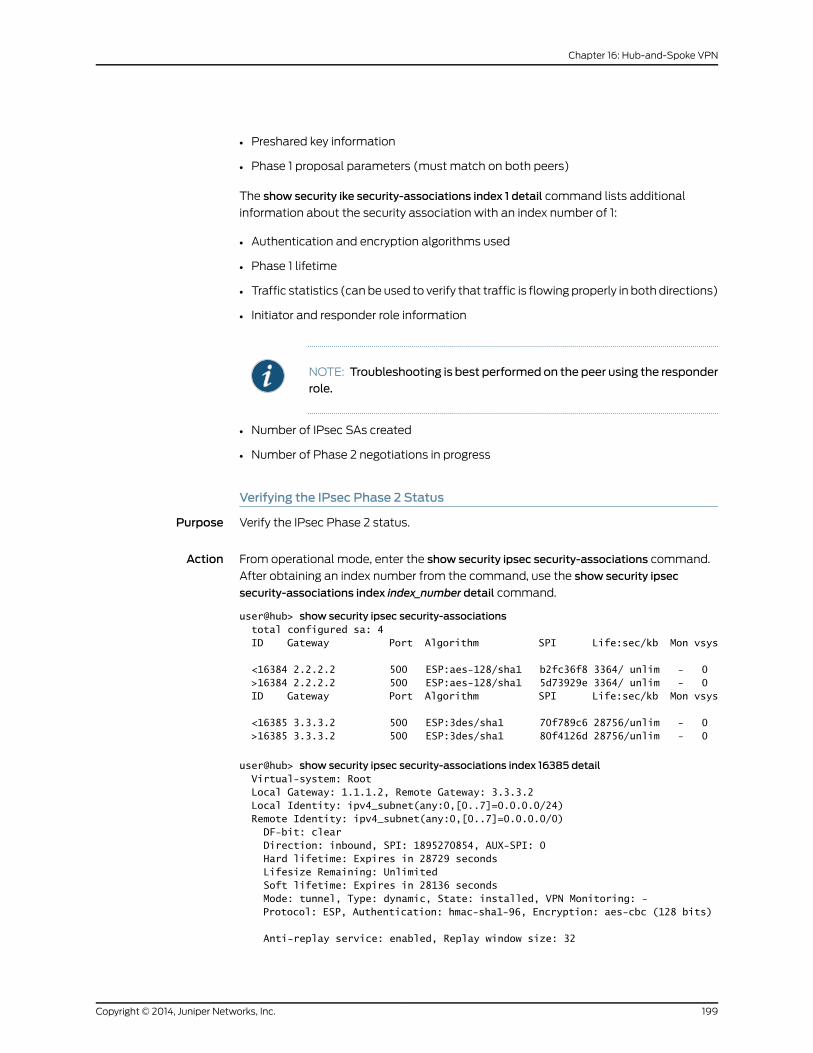
• Preshared key information
• Phase 1 proposal parameters (must match on both peers)
The show security ike security-associations index 1 detail command lists additional
information about the security association with an index number of 1:
• Authentication and encryption algorithms used
• Phase 1 lifetime
• Traffic statistics (can be used to verify that traffic is flowing properly in both directions)
• Initiator and responder role information
NOTE: Troubleshooting is best performedon the peer using the responderrole.
• Number of IPsec SAs created
• Number of Phase 2 negotiations in progress
Verifying the IPsec Phase 2 Status
Purpose Verify the IPsec Phase 2 status.
Action From operational mode, enter the show security ipsec security-associations command.
After obtaining an index number from the command, use the show security ipsec
security-associations index index_number detail command.
user@hub> show security ipsec security-associations total configured sa: 4 ID Gateway Port Algorithm SPI Life:sec/kb Mon vsys
<16384 2.2.2.2 500 ESP:aes-128/sha1 b2fc36f8 3364/ unlim - 0 >16384 2.2.2.2 500 ESP:aes-128/sha1 5d73929e 3364/ unlim - 0 ID Gateway Port Algorithm SPI Life:sec/kb Mon vsys
<16385 3.3.3.2 500 ESP:3des/sha1 70f789c6 28756/unlim - 0 >16385 3.3.3.2 500 ESP:3des/sha1 80f4126d 28756/unlim - 0
user@hub> show security ipsec security-associations index 16385 detail Virtual-system: Root Local Gateway: 1.1.1.2, Remote Gateway: 3.3.3.2 Local Identity: ipv4_subnet(any:0,[0..7]=0.0.0.0/24) Remote Identity: ipv4_subnet(any:0,[0..7]=0.0.0.0/0) DF-bit: clear Direction: inbound, SPI: 1895270854, AUX-SPI: 0 Hard lifetime: Expires in 28729 seconds Lifesize Remaining: Unlimited Soft lifetime: Expires in 28136 seconds Mode: tunnel, Type: dynamic, State: installed, VPN Monitoring: - Protocol: ESP, Authentication: hmac-sha1-96, Encryption: aes-cbc (128 bits)
Anti-replay service: enabled, Replay window size: 32
199Copyright © 2014, Juniper Networks, Inc.
Chapter 16: Hub-and-Spoke VPN
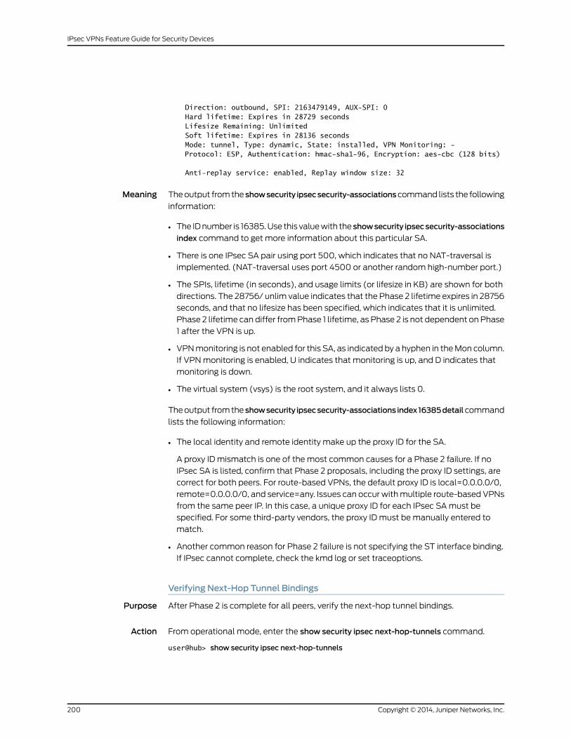
Direction: outbound, SPI: 2163479149, AUX-SPI: 0 Hard lifetime: Expires in 28729 seconds Lifesize Remaining: Unlimited Soft lifetime: Expires in 28136 seconds Mode: tunnel, Type: dynamic, State: installed, VPN Monitoring: - Protocol: ESP, Authentication: hmac-sha1-96, Encryption: aes-cbc (128 bits)
Anti-replay service: enabled, Replay window size: 32
Meaning The output from the showsecurity ipsecsecurity-associationscommand lists the following
information:
• The ID number is 16385. Use this value with the showsecurity ipsecsecurity-associations
index command to get more information about this particular SA.
• There is one IPsec SA pair using port 500, which indicates that no NAT-traversal is
implemented. (NAT-traversal uses port 4500 or another random high-number port.)
• The SPIs, lifetime (in seconds), and usage limits (or lifesize in KB) are shown for both
directions. The 28756/ unlim value indicates that the Phase 2 lifetime expires in 28756
seconds, and that no lifesize has been specified, which indicates that it is unlimited.
Phase 2 lifetime can differ from Phase 1 lifetime, as Phase 2 is not dependent on Phase
1 after the VPN is up.
• VPN monitoring is not enabled for this SA, as indicated by a hyphen in the Mon column.
If VPN monitoring is enabled, U indicates that monitoring is up, and D indicates that
monitoring is down.
• The virtual system (vsys) is the root system, and it always lists 0.
The output from the showsecurity ipsecsecurity-associations index16385detailcommand
lists the following information:
• The local identity and remote identity make up the proxy ID for the SA.
A proxy ID mismatch is one of the most common causes for a Phase 2 failure. If no
IPsec SA is listed, confirm that Phase 2 proposals, including the proxy ID settings, are
correct for both peers. For route-based VPNs, the default proxy ID is local=0.0.0.0/0,
remote=0.0.0.0/0, and service=any. Issues can occur with multiple route-based VPNs
from the same peer IP. In this case, a unique proxy ID for each IPsec SA must be
specified. For some third-party vendors, the proxy ID must be manually entered to
match.
• Another common reason for Phase 2 failure is not specifying the ST interface binding.
If IPsec cannot complete, check the kmd log or set traceoptions.
Verifying Next-Hop Tunnel Bindings
Purpose After Phase 2 is complete for all peers, verify the next-hop tunnel bindings.
Action From operational mode, enter the show security ipsec next-hop-tunnels command.
user@hub> show security ipsec next-hop-tunnels
Copyright © 2014, Juniper Networks, Inc.200
IPsec VPNs Feature Guide for Security Devices

Next-hop gateway interface IPSec VPN name Flag10.11.11.11 st0.0 sunnyvale-vpn Static10.11.11.12 st0.0 westford-vpn Auto
Meaning The next-hop gateways are the IP addresses for the st0 interfaces of all remote spoke
peers. The next hop should be associated with the correct IPsec VPN name. If no NHTB
entry exists, there is no way for the hub device to differentiate which IPsec VPN is
associated with which next hop.
The Flag field has one of the following values:
• Static— NHTB was manually configured in the st0.0 interface configurations, which is
required if the peer is not an SRX Series device.
• Auto— NHTB was not configured, but the entry was automatically populated into the
NHTB table during Phase 2 negotiations between two SRX Series devices
There is no NHTB table for any of the spoke sites in this example. From the spoke
perspective, the st0 interface is still a point-to-point link with only one IPsec VPN binding.
Verifying Static Routes for Remote Peer Local LANs
Purpose Verify that the static route references the spoke peer’s st0 IP address.
Action From operational mode, enter the show route command.
user@hub> show route 192.168.168.10inet.0: 9 destinations, 9 routes (9 active, 0 holddown, 0 hidden)+ = Active Route, - = Last Active, * = Both
192.168.168.0/24 *[Static/5] 00:08:33 > to 10.11.11.11 via st0.0
user@hub> show route 192.168.178.10inet.0: 9 destinations, 9 routes (9 active, 0 holddown, 0 hidden)+ = Active Route, - = Last Active, * = Both
192.168.178.0/24 *[Static/5] 00:04:04 > to 10.11.11.12 via st0.0
The next hop is the remote peer’s st0 IP address, and both routes point to st0.0 as the
outgoing interface.
Reviewing Statistics and Errors for an IPsec Security Association
Purpose Review ESP and authentication header counters and errors for an IPsec security
association.
Action From operational mode, enter the show security ipsec statistics index command.
user@hub> show security ipsec statistics index 16385ESP Statistics: Encrypted bytes: 920 Decrypted bytes: 6208 Encrypted packets: 5
201Copyright © 2014, Juniper Networks, Inc.
Chapter 16: Hub-and-Spoke VPN

Decrypted packets: 87AH Statistics: Input bytes: 0 Output bytes: 0 Input packets: 0 Output packets: 0Errors: AH authentication failures: 0, Replay errors: 0 ESP authentication failures: 0, ESP decryption failures: 0 Bad headers: 0, Bad trailers: 0
You can also use the show security ipsec statistics command to review statistics and
errors for all SAs.
To clear all IPsec statistics, use the clear security ipsec statistics command.
Meaning If you see packet loss issues across a VPN, you can run the show security ipsec statistics
or show security ipsec statistics detail command several times to confirm that the
encrypted and decrypted packet counters are incrementing. You should also check
whether the other error counters are incrementing.
Testing Traffic Flow Across the VPN
Purpose Verify the traffic flow across the VPN.
Action You can use theping command from the SRX Series device to test traffic flow to a remote
host PC. Make sure that you specify the source interface so that the route lookup is correct
and the appropriate security zones are referenced during policy lookup.
From operational mode, enter the ping command.
user@hub> ping 192.168.168.10 interface ge-0/0/0 count 5PING 192.168.168.10 (192.168.168.10): 56 data bytes64 bytes from 192.168.168.10: icmp_seq=0 ttl=127 time=8.287 ms64 bytes from 192.168.168.10: icmp_seq=1 ttl=127 time=4.119 ms64 bytes from 192.168.168.10: icmp_seq=2 ttl=127 time=5.399 ms64 bytes from 192.168.168.10: icmp_seq=3 ttl=127 time=4.361 ms64 bytes from 192.168.168.10: icmp_seq=4 ttl=127 time=5.137 ms
--- 192.168.168.10 ping statistics ---5 packets transmitted, 5 packets received, 0% packet lossround-trip min/avg/max/stddev = 4.119/5.461/8.287/1.490 ms
You can also use the ping command from the SSG Series device.
user@hub> ping 10.10.10.10 from ethernet0/6Type escape sequence to abortSending 5, 100-byte ICMP Echos to 10.10.10.10, timeout is 1 seconds from ethernet0/6!!!!!Success Rate is 100 percent (5/5), round-trip time min/avg/max=4/4/5 ms
ssg-> ping 192.168.178.10 from ethernet0/6Type escape sequence to abortSending 5, 100-byte ICMP Echos to 192.168.178.10, timeout is 1 seconds fromethernet0/6
Copyright © 2014, Juniper Networks, Inc.202
IPsec VPNs Feature Guide for Security Devices

!!!!!Success Rate is 100 percent (5/5), round-trip time min/avg/max=8/8/10 ms
Meaning If the ping command fails from the SRX Series or SSG Series device, there might be a
problem with the routing, security policies, end host, or encryption and decryption of ESP
packets.
RelatedDocumentation
• Understanding Hub-and-Spoke VPNs on page 31
• Example: Configuring a Route-Based VPN on page 61
• Example: Configuring a Policy-Based VPN on page 125
• IPsec VPNs Feature Guide for Security Devices
203Copyright © 2014, Juniper Networks, Inc.
Chapter 16: Hub-and-Spoke VPN

Copyright © 2014, Juniper Networks, Inc.204
IPsec VPNs Feature Guide for Security Devices

CHAPTER 17
Loopback Interface for High AvailabilityVPN
• Example: Configuring Redundancy Groups for Loopback Interfaces on page 205
Example: Configuring Redundancy Groups for Loopback Interfaces
Supported Platforms LN Series, SRX Series
This example shows how to configure a redundancy group (RG) for a loopback interface
in order to prevent VPN failure. Redundancy groups are used to bundle interfaces into a
group for failover purpose in a chassis cluster setup.
• Requirements on page 205
• Overview on page 205
• Configuration on page 207
• Verification on page 210
Requirements
This example uses the following hardware and software:
• A pair of supported chassis cluster SRX Series devices
• An SSG140 device or equivalent
• Two switches
• Junos OS Release 12.1x44-D10 for SRX Series Services Gateways
Before you begin:
Understand chassis cluster redundant Ethernet interfaces. See Understanding Chassis
Cluster Redundant Ethernet Interfaces.
Overview
An Internet Key Exchange (IKE) gateway needs an external interface to communicate
with a peer device. In a chassis cluster setup, the node on which the external interface is
active selects a Services Processing Unit (SPU) to support the VPN tunnel. IKE and IPsec
205Copyright © 2014, Juniper Networks, Inc.
packets are processed on that SPU. Therefore, the active external interface decides the
anchor SPU.
In a chassis cluster setup, this external interface can be the reth interface or a standalone
interface. These interfaces can go down when the physical interfaces are down. Therefore,
you can configure loopback interfaces to reach the peer gateway as they are alternate
physical interfaces. Loopback interfaces can be configured on any redundancy group.
This redundancy group configuration is only checked for VPN packets, because only VPN
packets must find the anchor SPU through the active interface.
NOTE: Youmust configure lo0.x in customer virtual router, since lo0.0 is indefault virtual router andonlyone loopback interface is allowed inonevirtualrouter.
Figure 18 on page 207 shows an example of a loopback chassis cluster VPN topology. In
this topology, the SRX Series chassis cluster device is located in Sunnyvale, California.
The SRX Series chassis cluster device works as a single gateway in this setup. The SSG
Series device (or a third-party device) is located in Chicago, Illinois. This device acts as
a peer device to the SRX chassis cluster and it helps to build a VPN tunnel.
Copyright © 2014, Juniper Networks, Inc.206
IPsec VPNs Feature Guide for Security Devices

Figure 18: Loopback Interface for Chassis Cluster VPN
Configuration
CLI QuickConfiguration
To quickly configure this example, copy the following commands, paste them into a text
file, remove any line breaks, change any details necessary to match your network
207Copyright © 2014, Juniper Networks, Inc.
Chapter 17: Loopback Interface for High Availability VPN
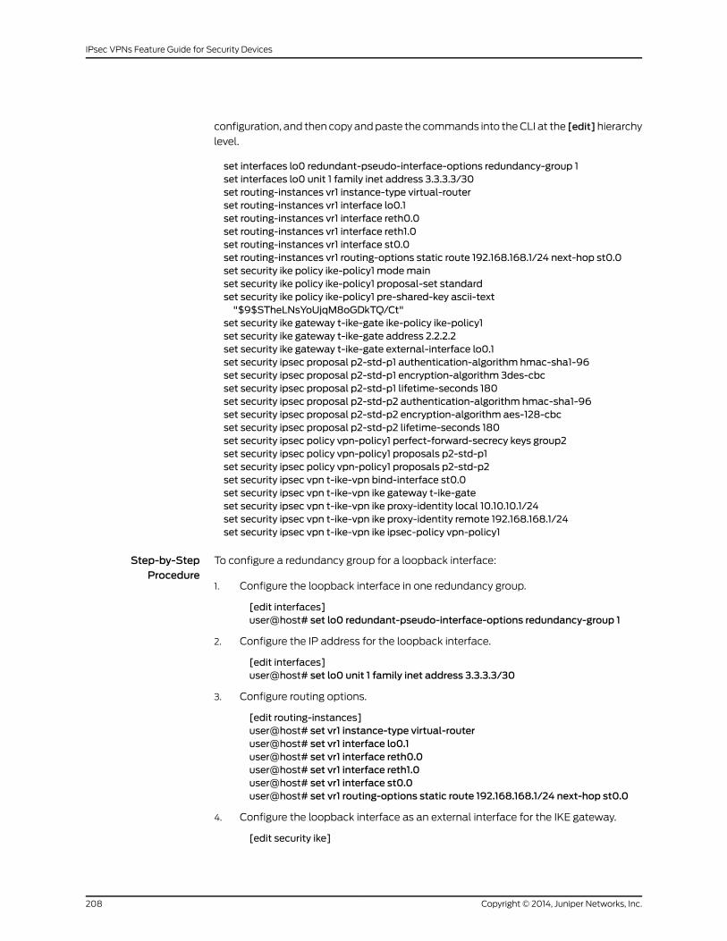
configuration, and then copy and paste the commands into the CLI at the [edit]hierarchy
level.
set interfaces lo0 redundant-pseudo-interface-options redundancy-group 1set interfaces lo0 unit 1 family inet address 3.3.3.3/30set routing-instances vr1 instance-type virtual-routerset routing-instances vr1 interface lo0.1set routing-instances vr1 interface reth0.0set routing-instances vr1 interface reth1.0set routing-instances vr1 interface st0.0set routing-instances vr1 routing-options static route 192.168.168.1/24 next-hop st0.0set security ike policy ike-policy1 modemainset security ike policy ike-policy1 proposal-set standardset security ike policy ike-policy1 pre-shared-key ascii-text"$9$STheLNsYoUjqM8oGDkTQ/Ct"
set security ike gateway t-ike-gate ike-policy ike-policy1set security ike gateway t-ike-gate address 2.2.2.2set security ike gateway t-ike-gate external-interface lo0.1set security ipsec proposal p2-std-p1 authentication-algorithm hmac-sha1-96set security ipsec proposal p2-std-p1 encryption-algorithm 3des-cbcset security ipsec proposal p2-std-p1 lifetime-seconds 180set security ipsec proposal p2-std-p2 authentication-algorithm hmac-sha1-96set security ipsec proposal p2-std-p2 encryption-algorithm aes-128-cbcset security ipsec proposal p2-std-p2 lifetime-seconds 180set security ipsec policy vpn-policy1 perfect-forward-secrecy keys group2set security ipsec policy vpn-policy1 proposals p2-std-p1set security ipsec policy vpn-policy1 proposals p2-std-p2set security ipsec vpn t-ike-vpn bind-interface st0.0set security ipsec vpn t-ike-vpn ike gateway t-ike-gateset security ipsec vpn t-ike-vpn ike proxy-identity local 10.10.10.1/24set security ipsec vpn t-ike-vpn ike proxy-identity remote 192.168.168.1/24set security ipsec vpn t-ike-vpn ike ipsec-policy vpn-policy1
Step-by-StepProcedure
To configure a redundancy group for a loopback interface:
Configure the loopback interface in one redundancy group.1.
[edit interfaces]user@host# set lo0 redundant-pseudo-interface-options redundancy-group 1
2. Configure the IP address for the loopback interface.
[edit interfaces]user@host# set lo0 unit 1 family inet address 3.3.3.3/30
3. Configure routing options.
[edit routing-instances]user@host# set vr1 instance-type virtual-routeruser@host# set vr1 interface lo0.1user@host# set vr1 interface reth0.0user@host# set vr1 interface reth1.0user@host# set vr1 interface st0.0user@host# set vr1 routing-options static route 192.168.168.1/24 next-hop st0.0
4. Configure the loopback interface as an external interface for the IKE gateway.
[edit security ike]
Copyright © 2014, Juniper Networks, Inc.208
IPsec VPNs Feature Guide for Security Devices
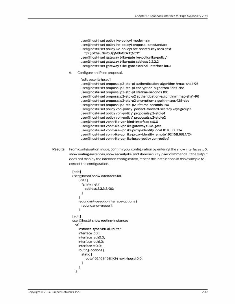
user@host# set policy ike-policy1 modemainuser@host# set policy ike-policy1 proposal-set standarduser@host# set policy ike-policy1 pre-shared-key ascii-text"$9$STheLNsYoUjqM8oGDkTQ/Ct"
user@host# set gateway t-ike-gate ike-policy ike-policy1user@host# set gateway t-ike-gate address 2.2.2.2user@host# set gateway t-ike-gate external-interface lo0.1
5. Configure an IPsec proposal.
[edit security ipsec]user@host# set proposal p2-std-p1 authentication-algorithm hmac-sha1-96user@host# set proposal p2-std-p1 encryption-algorithm 3des-cbcuser@host# set proposal p2-std-p1 lifetime-seconds 180user@host# set proposal p2-std-p2 authentication-algorithm hmac-sha1-96user@host# set proposal p2-std-p2 encryption-algorithm aes-128-cbcuser@host# set proposal p2-std-p2 lifetime-seconds 180user@host# set policy vpn-policy1 perfect-forward-secrecy keys group2user@host# set policy vpn-policy1 proposals p2-std-p1user@host# set policy vpn-policy1 proposals p2-std-p2user@host# set vpn t-ike-vpn bind-interface st0.0user@host# set vpn t-ike-vpn ike gateway t-ike-gateuser@host# set vpn t-ike-vpn ike proxy-identity local 10.10.10.1/24user@host# set vpn t-ike-vpn ike proxy-identity remote 192.168.168.1/24user@host# set vpn t-ike-vpn ike ipsec-policy vpn-policy1
Results From configuration mode, confirm your configuration by entering the show interfaces lo0,
showrouting-instances, showsecurity ike, and showsecurity ipseccommands. If the output
does not display the intended configuration, repeat the instructions in this example to
correct the configuration.
[edit]user@host# show interfaces lo0
unit 1 {family inet {address 3.3.3.3/30;
}}redundant-pseudo-interface-options {redundancy-group 1;
}
[edit]user@host# show routing-instancesvr1 {instance-type virtual-router;interface lo0.1;interface reth0.0;interface reth1.0;interface st0.0;routing-options {static {route 192.168.168.1/24 next-hop st0.0;
}}
}
209Copyright © 2014, Juniper Networks, Inc.
Chapter 17: Loopback Interface for High Availability VPN
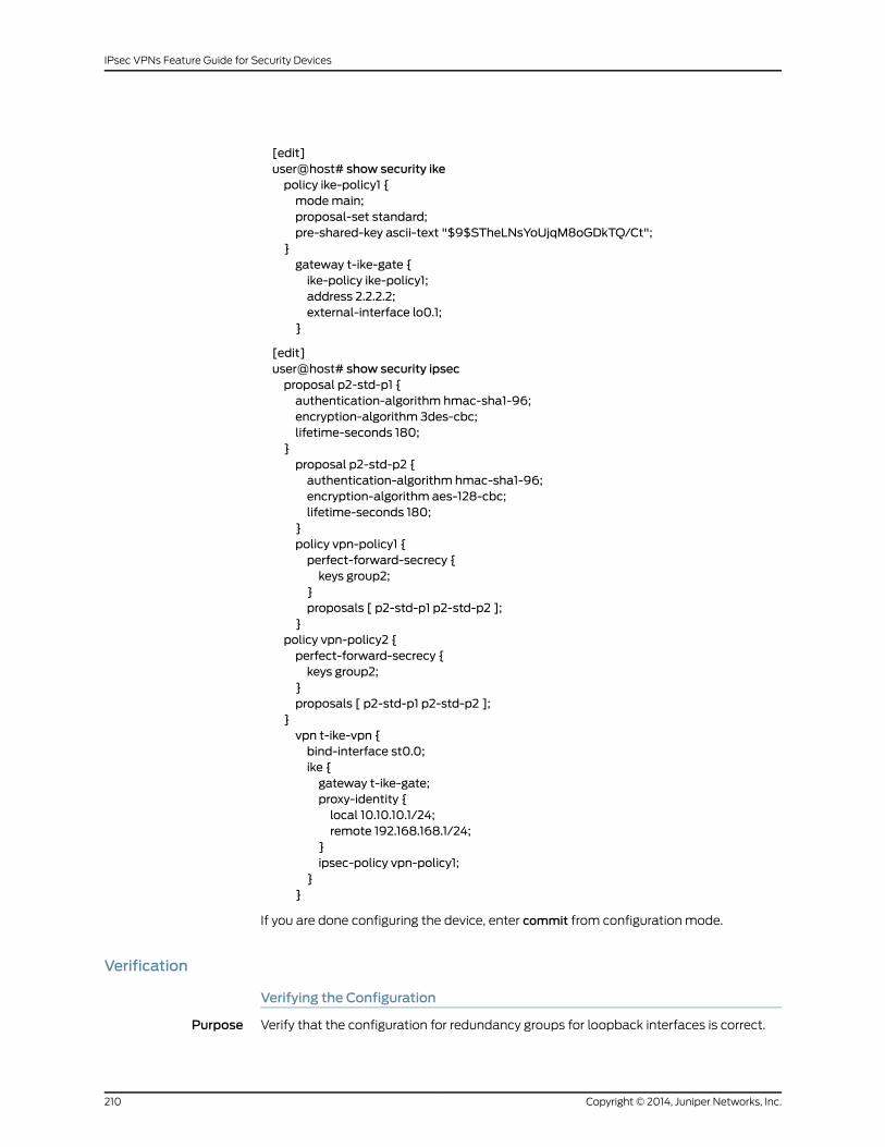
[edit]user@host# show security ikepolicy ike-policy1 {modemain;proposal-set standard;pre-shared-key ascii-text "$9$STheLNsYoUjqM8oGDkTQ/Ct";
}gateway t-ike-gate {ike-policy ike-policy1;address 2.2.2.2;external-interface lo0.1;
}
[edit]user@host# show security ipsecproposal p2-std-p1 {authentication-algorithm hmac-sha1-96;encryption-algorithm 3des-cbc;lifetime-seconds 180;
}proposal p2-std-p2 {authentication-algorithm hmac-sha1-96;encryption-algorithm aes-128-cbc;lifetime-seconds 180;
}policy vpn-policy1 {perfect-forward-secrecy {keys group2;
}proposals [ p2-std-p1 p2-std-p2 ];
}policy vpn-policy2 {perfect-forward-secrecy {keys group2;
}proposals [ p2-std-p1 p2-std-p2 ];
}vpn t-ike-vpn {bind-interface st0.0;ike {gateway t-ike-gate;proxy-identity {local 10.10.10.1/24;remote 192.168.168.1/24;
}ipsec-policy vpn-policy1;
}}
If you are done configuring the device, enter commit from configuration mode.
Verification
Verifying the Configuration
Purpose Verify that the configuration for redundancy groups for loopback interfaces is correct.
Copyright © 2014, Juniper Networks, Inc.210
IPsec VPNs Feature Guide for Security Devices

Action From operational mode, enter the show chassis cluster interfaces command.
user@host> show chassis cluster interfacesControl link status: UpControl interfaces:Index Interface Status0 em0Up1 em1 DownFabric link status: UpFabric interfaces:Name Child-interface Statusfab0 ge-0/0/7 Up / Upfab0fab1 ge-13/0/7 Up / Upfab1Redundant-ethernet Information:Name Status Redundancy-groupreth0 Up 1reth1 Up 1reth2 Up 1reth3 Down Not configuredreth4 Down Not configuredRedundant-pseudo-interface Information:Name Status Redundancy-grouplo0 Up 1
Meaning The show chassis cluster interfaces command displays the chassis cluster interfaces
information. If the status of the Redundant-pseudo-interface Information field shows
the lo0 interface as Up and the status of the Redundant-ethernet Information field shows
reth0, reth1, and reth2 fields as Up then your configuration is correct.
RelatedDocumentation
• Understanding Loopback Interface for a High Availability VPN on page 33
211Copyright © 2014, Juniper Networks, Inc.
Chapter 17: Loopback Interface for High Availability VPN

Copyright © 2014, Juniper Networks, Inc.212
IPsec VPNs Feature Guide for Security Devices
CHAPTER 18
IPv6 IPsec
• IPv6 IPsec Configuration Overview on page 213
• Example: Configuring an IPv6 IPsec Manual VPN on page 214
• Example: Configuring an IPv6 AutoKey IKE Policy-Based VPN on page 216
IPv6 IPsec Configuration Overview
Supported Platforms J Series, LN Series, SRX100, SRX210, SRX240, SRX650
Juniper Networks supports two types of IPv6 IPsec VPN configurations—Manual and
AutoKey IKE with preshared keys.
• Manual VPN—In a Manual VPN configuration, the secret keys and security associations
(SAs) are manually configured on the tunnel endpoints using the Manual key
mechanism. To create an IPv6 IPsec Manual VPN, see “Example: Configuring an IPv6
IPsec Manual VPN” on page 214.
• AutoKey IKE VPN—In an AutoKey IKE VPN configuration, the secret keys and SAs are
automatically created using the AutoKey IKE mechanism. To set up an IPv6 AutoKey
IKE VPN, two phases of negotiations are required—Phase 1 and Phase 2.
• Phase 1—In this phase, the participants establish a secure channel for negotiating
the IPsec SAs. For more information on Phase 1 negotiations, see “Understanding
Phase 1 of IKE Tunnel Negotiation” on page 18.
• Phase 2—In this phase, the participants negotiate the IPsec SAs for authenticating
and encrypting the IPv6 data packets. For more information on Phase 2 negotiations,
see “Understanding Phase 2 of IKE Tunnel Negotiation” on page 20.
To create an IPv6 AutoKey IKE policy-based VPN, see “Example: Configuring an IPv6
AutoKey IKE Policy-Based VPN” on page 216.
RelatedDocumentation
Understanding IPv6 IKE and IPsec Packet Processing on page 37•
• Example: Configuring an IPv6 IPsec Manual VPN on page 214
• Example: Configuring an IPv6 AutoKey IKE Policy-Based VPN on page 216
• IPsec VPNs Feature Guide for Security Devices
213Copyright © 2014, Juniper Networks, Inc.

Example: Configuring an IPv6 IPsecManual VPN
Supported Platforms J Series, LN Series, SRX100, SRX210, SRX240, SRX650
This example shows how to configure an IPv6 IPsec Manual VPN.
• Requirements on page 214
• Overview on page 214
• Configuration on page 214
• Verification on page 216
Requirements
Before you begin:
• Understand how VPNs work. See “VPN Overview” on page 3.
• Understand IPv6 IPsec packet processing. See “Understanding IPv6 IKE and IPsec
Packet Processing” on page 37.
Overview
In a Manual VPN configuration, the secret keys are manually configured on the two IPsec
endpoints.
In this example, you:
• Configure the authentication parameters for a VPN named vpn-sunnyvale.
• Configure the encryption parameters for vpn-sunnyvale.
• Specify the outgoing interface for the SA.
• Specify the IPv6 address of the peer.
• Define the IPsec protocol. Select the ESP protocol because the configuration includes
both authentication and encryption.
• Configure a security parameter index (SPI).
Configuration
CLI QuickConfiguration
To quickly configure this example, copy the following commands, paste them into a text
file, remove any line breaks, change any details necessary to match your network
configuration, and then copy and paste the commands into the CLI at the [edit]hierarchy
level.
set security ipsec vpn vpn-sunnyvalemanual authentication algorithm hmac-md5–96key ascii-text 1111111111111111
setsecurity ipsecvpnvpn-sunnyvalemanualencryptionalgorithm3des-cbckeyascii-text111111111111111111111111
set security ipsec vpn vpn-sunnyvalemanual external-interface ge-0/0/14.0set security ipsec vpn vpn-sunnyvalemanual gateway 1212::1112set security ipsec vpn vpn-sunnyvalemanual protocol esp
Copyright © 2014, Juniper Networks, Inc.214
IPsec VPNs Feature Guide for Security Devices
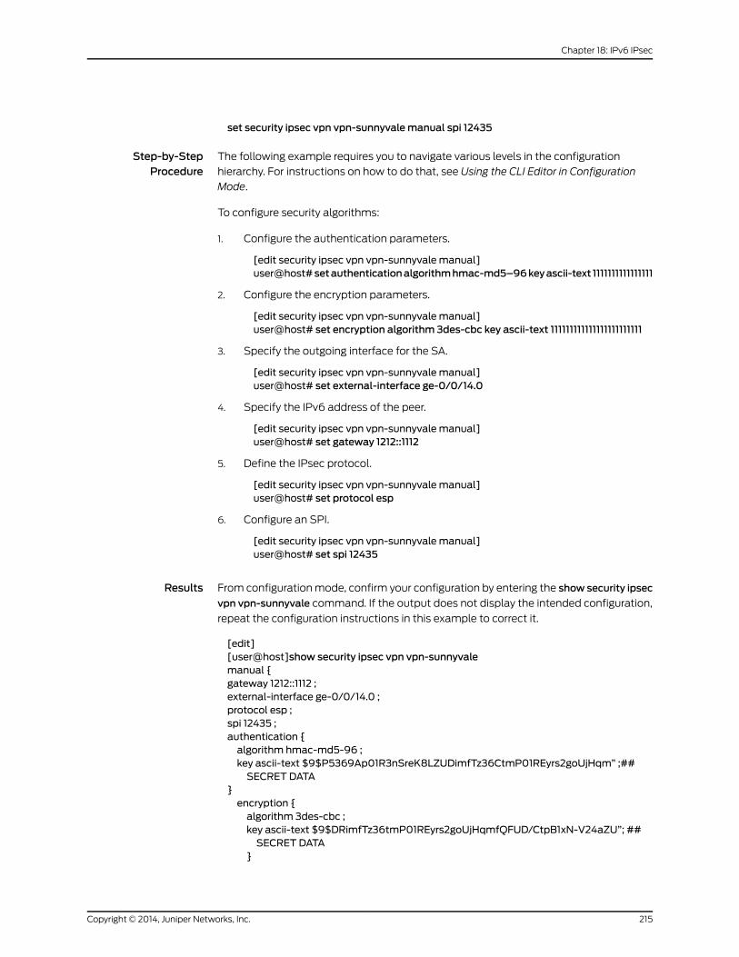
set security ipsec vpn vpn-sunnyvalemanual spi 12435
Step-by-StepProcedure
The following example requires you to navigate various levels in the configuration
hierarchy. For instructions on how to do that, see Using the CLI Editor in Configuration
Mode.
To configure security algorithms:
1. Configure the authentication parameters.
[edit security ipsec vpn vpn-sunnyvale manual]user@host#setauthenticationalgorithmhmac-md5–96keyascii-text 1111111111111111
2. Configure the encryption parameters.
[edit security ipsec vpn vpn-sunnyvale manual]user@host# set encryption algorithm 3des-cbc key ascii-text 111111111111111111111111
3. Specify the outgoing interface for the SA.
[edit security ipsec vpn vpn-sunnyvale manual]user@host# set external-interface ge-0/0/14.0
4. Specify the IPv6 address of the peer.
[edit security ipsec vpn vpn-sunnyvale manual]user@host# set gateway 1212::1112
5. Define the IPsec protocol.
[edit security ipsec vpn vpn-sunnyvale manual]user@host# set protocol esp
6. Configure an SPI.
[edit security ipsec vpn vpn-sunnyvale manual]user@host# set spi 12435
Results From configuration mode, confirm your configuration by entering the show security ipsec
vpn vpn-sunnyvale command. If the output does not display the intended configuration,
repeat the configuration instructions in this example to correct it.
[edit][user@host]show security ipsec vpn vpn-sunnyvalemanual {gateway 1212::1112 ;external-interface ge-0/0/14.0 ;protocol esp ;spi 12435 ;authentication {algorithm hmac-md5-96 ;key ascii-text $9$P5369Ap01R3nSreK8LZUDimfTz36CtmP01REyrs2goUjHqm” ;##SECRET DATA
}encryption {algorithm 3des-cbc ;key ascii-text $9$DRimfTz36tmP01REyrs2goUjHqmfQFUD/CtpB1xN-V24aZU”; ##SECRET DATA
}
215Copyright © 2014, Juniper Networks, Inc.
Chapter 18: IPv6 IPsec

}
Verification
To confirm that the configuration is working properly, perform this task:
• Verifying Security Algorithms on page 216
Verifying Security Algorithms
Purpose Determine if security algorithms are applied or not.
Action From operational mode, enter the show security ipsec security-associations command.
RelatedDocumentation
Understanding IPv6 IKE and IPsec Packet Processing on page 37•
• IPv6 IPsec Configuration Overview on page 213
• Example: Configuring an IPv6 AutoKey IKE Policy-Based VPN on page 216
• IPsec VPNs Feature Guide for Security Devices
Example: Configuring an IPv6 AutoKey IKE Policy-Based VPN
Supported Platforms J Series, LN Series, SRX100, SRX210, SRX240, SRX650
This example shows how to configure a policy-based IPv6 AutoKey IKE VPN to allow
IPv6 data to be securely transferred between the branch office and the corporate office.
• Requirements on page 216
• Overview on page 216
• Configuration on page 220
• Verification on page 229
Requirements
This example uses the following hardware:
• SRX240 device
Before you begin:
• Understand how VPNs work. See “VPN Overview” on page 3.
• Understand IPv6 IKE and IPsec packet processing. See “Understanding IPv6 IKE and
IPsec Packet Processing” on page 37.
Overview
In this example, you configure an IPv6 IKE policy-based VPN for a branch office in Chicago,
Illinois, because you do not need to conserve tunnel resources or configure many security
Copyright © 2014, Juniper Networks, Inc.216
IPsec VPNs Feature Guide for Security Devices

policies to filter traffic through the tunnel. Users in the Chicago office will use the VPN
to connect to their corporate headquarters in Sunnyvale, California.
Figure 19 on page 217 shows an example of an IPv6 IKE policy-based VPN topology. In
this topology, one SRX Series device is located in Sunnyvale, and another SRX Series
device (this can be a second SRX Series device or a third-party device) is located in
Chicago.
Figure 19: IPv6 IKE Policy-Based VPN Topology
Trust zone
1111::abcd/128
e0/01111::1112/64
e0/61111::1212/128
Untrustzone
Internet
Trust zone
Chicago
ge-0/0/14.01212::1111/64
SRX Series device
SRX Series device
Sunnyvale
1212::abcd/64
ge-0/0/15.01111::1111/64
217Copyright © 2014, Juniper Networks, Inc.
Chapter 18: IPv6 IPsec

In this example, you configure interfaces, an IPv6 default route, security zones, and
address books. Then you configure IKE Phase 1, IPsec Phase 2, a security policy, and
TCP-MSS parameters. See Table 44 on page 218 through Table 48 on page 220.
Table 44: Interface, Security Zone, and Address Book Information
Configuration ParametersNameFeature
1212::1111/64ge-0/0/14.0Interfaces
1111::1111/64ge-0/0/15.0
• All system services are allowed.
• The ge-0/0/14.0 interface is bound tothis zone.
trustSecurity zones
• IKE is the only allowed system service.
• The ge-0/0/15.0 interface is bound tothis zone.
untrust
• This address is for the trust zone’saddress book.
• The address for this address book entryis 1212::abcd/64.
sunnyvaleAddress book entries
• This address is for the untrust zone’saddress book.
• The address for this address book entryis 1111::abcd/128.
chicago
Table 45: IPv6 IKE Phase 1 Configuration Parameters
Configuration ParametersNameFeature
• Authentication method: pre-shared-keys
• Diffie-Hellman group: group2
• Authentication algorithm: sha1
• Encryption algorithm: aes-128-cbc
ipv6-ike-phase1-proposalProposal
• Mode: Aggressive
• Proposal reference: ipv6-ike-phase1-proposal
• IKE Phase 1 policy authentication method: pre-shared-key ascii-text
ipv6-ike-phase1-policyPolicy
• IKE policy reference: ipv6-ike-phase1-policy
• External interface: ge-0/0/15.0
• Gateway address: 1111::1112/64
gw-chicagoGateway
Copyright © 2014, Juniper Networks, Inc.218
IPsec VPNs Feature Guide for Security Devices

Table 46: IPv6 IPsec Phase 2 Configuration Parameters
Configuration ParametersNameFeature
• Protocol: esp
• Authentication algorithm: hmac-sha1-96
• Encryption algorithm: aes-128-cbc
ipv6-ipsec-phase2-proposalProposal
• Proposal reference: ipv6-ipsec-phase2-proposal
• PFS: Diffie-Hellman group2
ipv6-ipsec-phase2-policyPolicy
• IKE gateway reference: gw-chicago
• IPsec policy reference: ipv6-ipsec-phase2-policy
ipv6-ike-vpn-chicagoVPN
Table 47: Security Policy Configuration Parameters
Configuration ParametersNamePurpose
• Match criteria:
• source-address sunnyvale
• destination-address chicago
• application any
• Permit action: tunnel ipsec-vpnipv6-ike-vpn-chicago
• Permit action: tunnel pair-policyipv6-vpn-untr-tr
ipv6-vpn-tr-untrThis security policy permits traffic from the trust zoneto the untrust zone.
• Match criteria:
• source-address chicago
• destination-address sunnyvale
• application any
• Permit action: tunnel ipsec-vpnipv6-ike-vpn-chicago
• Permit action: tunnel pair-policyipv6-vpn-tr-untr
ipv6-vpn-untr-trThis security policy permits traffic from the untrust zoneto the trust zone.
• Match criteria:
• source-address any
• source-destination any
• application any
• Action: permit
permit-anyThis security policy permits all traffic from the trustzone to the untrust zone.
NOTE: You must put the ipv6-vpn-tr-untr policy beforethe permit-any security policy. Junos OS performs asecurity policy lookup starting at the top of the list. Ifthe permit-any policy comes before theipv6-vpn-tr-untr policy, all traffic from the trust zonewill match the permit-any policy and be permitted.Thus, no traffic will ever match the ipv6-vpn-tr-untrpolicy.
219Copyright © 2014, Juniper Networks, Inc.
Chapter 18: IPv6 IPsec

Table 48: TCP-MSS Configuration Parameters
ConfigurationParametersPurpose
MSS value: 1350TCP-MSS is negotiated as part of the TCP three-way handshake and limits the maximum size of aTCP segment to better fit the MTU limits on a network. This is especially important for VPN traffic, asthe IPsec encapsulation overhead, along with the IP and frame overhead, can cause the resulting ESPpacket to exceed the MTU of the physical interface, thus causing fragmentation. Fragmentation resultsin increased use of bandwidth and device resources.
NOTE: We recommend a value of 1350 as the starting point for most Ethernet-based networks withan MTU of 1500 or greater. You might need to experiment with different TCP-MSS values to obtainoptimal performance. For example, you might need to change the value if any device in the path hasa lower MTU, or if there is any additional overhead such as PPP or Frame Relay.
Configuration
Configuring Basic Network, Security Zone, and Address Book Information
CLI QuickConfiguration
To quickly configure this section of the example, copy the following commands, paste
them into a text file, remove any line breaks, change any details necessary to match your
network configuration, and then copy and paste the commands into the CLI at the [edit]
hierarchy level.
set interfaces ge-0/0/14 unit 0 family inet6 address 1212::1111/64set interfaces ge-0/0/15 unit 0 family inet6 address 1111::1111/64set routing-options static route 0.0.0.0/0 next-hop 1.1.1.1set security zones security-zone untrust interfaces ge-0/0/15.0set security zones security-zone untrust host-inbound-traffic system-services ikeset security zones security-zone trust interfaces ge-0/0/14.0set security zones security-zone trust host-inbound-traffic system-services allset security address-book book1 address sunnyvale 1212::abcd/64set security address-book book1 attach zone trustset security address-book book2 address chicago 1111::abcd/64set security address-book book2 attach zone untrust
Step-by-StepProcedure
The following example requires you to navigate various levels in the configuration
hierarchy. For instructions on how to do that, see Using the CLI Editor in Configuration
Mode.
To configure basic network, security zone, and address book information:
1. Configure Ethernet interface information.
[edit]user@host# set interfaces ge-0/0/14 unit 0 family inet6 address 1212::1111/64user@host# set interfaces ge-0/0/15 unit 0 family inet6 address 1111::1111/64
2. Configure static route information.
[edit]user@host# set routing-options static route 0.0.0.0/0 next-hop 1.1.1.1
3. Configure the untrust security zone.
[edit]user@host# edit security zones security-zone untrust
Copyright © 2014, Juniper Networks, Inc.220
IPsec VPNs Feature Guide for Security Devices

4. Assign an interface to the untrust security zone.
[edit security zones security-zone untrust]user@host# set interfaces ge-0/0/15.0
5. Specify allowed system services for the untrust security zone.
[edit security zones security-zone untrust]user@host# set host-inbound-traffic system-services ike
6. Configure the trust security zone.
[edit]user@host# edit security zones security-zone trust
7. Assign an interface to the trust security zone.
[edit security zones security-zone trust]user@host# set interfaces ge-0/0/14.0
8. Specify allowed system services for the trust security zone.
[edit security zones security-zone trust]user@host# set host-inbound-traffic system-services all
9. Create an address book and attach a zone to it.
[edit security address-book book1]user@host# set address sunnyvale 1212::abcd/64user@host# set attach zone trust
10. Create another address book and attach a zone to it.
[edit security address-book book2]user@host# set address chicago 1111::abcd/64user@host# set attach zone untrust
Results From configuration mode, confirm your configuration by entering the show interfaces,
show routing-options, show security zones, and show security address-book commands.
If the output does not display the intended configuration, repeat the configuration
instructions in this example to correct it.
[edit]user@host# show interfacesge-0/0/14 {unit 0 {family inet6 {address 1212::1111/64;
}}
}ge-0/0/15 {unit 0 {family inet6 {address 1111::1111/64;
}}
}
[edit]
221Copyright © 2014, Juniper Networks, Inc.
Chapter 18: IPv6 IPsec

user@host# show routing-optionsstatic {route 0.0.0.0/0 next-hop 1.1.1.1;
}
[edit]user@host# show security zonessecurity-zone untrust {host-inbound-traffic {system-services {ike;
}}interfaces {ge-0/0/15.0;
}}security-zone trust {host-inbound-traffic {system-services {all;
}}interfaces {ge-0/0/14.0;
}}[edit]user@host# show security address-bookbook1 {address sunnyvale 1212::abcd/64;attach {zone trust;
}}book2 {address chicago 1111::abcd/64;attach {zone untrust;
}}
If you are done configuring the device, enter commit from configuration mode.
Configuring IKE
CLI QuickConfiguration
To quickly configure this section of the example, copy the following commands, paste
them into a text file, remove any line breaks, change any details necessary to match your
network configuration, and then copy and paste the commands into the CLI at the [edit]
hierarchy level.
setsecurity ikeproposal ipv6-ike-phase1-proposalauthentication-methodpre-shared-keysset security ike proposal ipv6-ike-phase1-proposal dh-group group2set security ike proposal ipv6-ike-phase1-proposal authentication-algorithm sha1set security ike proposal ipv6-ike-phase1-proposal encryption-algorithm aes-128-cbcset security ike policy ipv6-ike-phase1-policymode aggressive
Copyright © 2014, Juniper Networks, Inc.222
IPsec VPNs Feature Guide for Security Devices
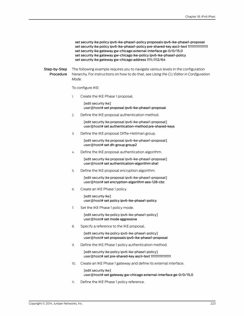
set security ike policy ipv6-ike-phase1-policy proposals ipv6-ike-phase1-proposalset security ike policy ipv6-ike-phase1-policy pre-shared-key ascii-text 1111111111111111set security ike gateway gw-chicago external-interface ge-0/0/15.0set security ike gateway gw-chicago ike-policy ipv6-ike-phase1-policyset security ike gateway gw-chicago address 1111::1112/64
Step-by-StepProcedure
The following example requires you to navigate various levels in the configuration
hierarchy. For instructions on how to do that, see Using the CLI Editor in Configuration
Mode.
To configure IKE:
1. Create the IKE Phase 1 proposal.
[edit security ike]user@host# set proposal ipv6-ike-phase1-proposal
2. Define the IKE proposal authentication method.
[edit security ike proposal ipv6-ike-phase1-proposal]user@host# set authentication-method pre-shared-keys
3. Define the IKE proposal Diffie-Hellman group.
[edit security ike proposal ipv6-ike-phase1-proposal]user@host# set dh-group group2
4. Define the IKE proposal authentication algorithm.
[edit security ike proposal ipv6-ike-phase1-proposal]user@host# set authentication-algorithm sha1
5. Define the IKE proposal encryption algorithm.
[edit security ike proposal ipv6-ike-phase1-proposal]user@host# set encryption-algorithm aes-128-cbc
6. Create an IKE Phase 1 policy.
[edit security ike]user@host# set policy ipv6-ike-phase1-policy
7. Set the IKE Phase 1 policy mode.
[edit security ike policy ipv6-ike-phase1-policy]user@host# setmode aggressive
8. Specify a reference to the IKE proposal.
[edit security ike policy ipv6-ike-phase1-policy]user@host# set proposals ipv6-ike-phase1-proposal
9. Define the IKE Phase 1 policy authentication method.
[edit security ike policy ipv6-ike-phase1-policy]user@host# set pre-shared-key ascii-text 1111111111111111
10. Create an IKE Phase 1 gateway and define its external interface.
[edit security ike]user@host# set gateway gw-chicago external-interface ge-0/0/15.0
11. Define the IKE Phase 1 policy reference.
223Copyright © 2014, Juniper Networks, Inc.
Chapter 18: IPv6 IPsec
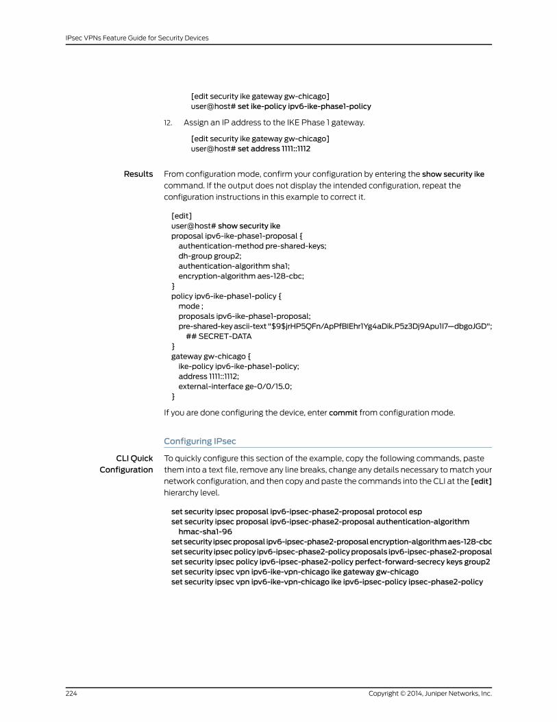
[edit security ike gateway gw-chicago]user@host# set ike-policy ipv6-ike-phase1-policy
12. Assign an IP address to the IKE Phase 1 gateway.
[edit security ike gateway gw-chicago]user@host# set address 1111::1112
Results From configuration mode, confirm your configuration by entering the show security ike
command. If the output does not display the intended configuration, repeat the
configuration instructions in this example to correct it.
[edit]user@host# show security ikeproposal ipv6-ike-phase1-proposal {authentication-method pre-shared-keys;dh-group group2;authentication-algorithm sha1;encryption-algorithm aes-128-cbc;
}policy ipv6-ike-phase1-policy {mode ;proposals ipv6-ike-phase1-proposal;pre-shared-keyascii-text"$9$jrHP5QFn/ApPfBIEhr1Yg4aDik.P5z3Dj9Apu1I7—dbgoJGD";## SECRET-DATA
}gateway gw-chicago {ike-policy ipv6-ike-phase1-policy;address 1111::1112;external-interface ge-0/0/15.0;
}
If you are done configuring the device, enter commit from configuration mode.
Configuring IPsec
CLI QuickConfiguration
To quickly configure this section of the example, copy the following commands, paste
them into a text file, remove any line breaks, change any details necessary to match your
network configuration, and then copy and paste the commands into the CLI at the [edit]
hierarchy level.
set security ipsec proposal ipv6-ipsec-phase2-proposal protocol espset security ipsec proposal ipv6-ipsec-phase2-proposal authentication-algorithmhmac-sha1-96
setsecurity ipsecproposal ipv6-ipsec-phase2-proposalencryption-algorithmaes-128-cbcsetsecurity ipsecpolicy ipv6-ipsec-phase2-policyproposals ipv6-ipsec-phase2-proposalset security ipsec policy ipv6-ipsec-phase2-policy perfect-forward-secrecy keys group2set security ipsec vpn ipv6-ike-vpn-chicago ike gateway gw-chicagoset security ipsec vpn ipv6-ike-vpn-chicago ike ipv6-ipsec-policy ipsec-phase2-policy
Copyright © 2014, Juniper Networks, Inc.224
IPsec VPNs Feature Guide for Security Devices

Step-by-StepProcedure
The following example requires you to navigate various levels in the configuration
hierarchy. For instructions on how to do that, see Using the CLI Editor in Configuration
Mode.
To configure IPsec:
1. Create an IPsec Phase 2 proposal.
[edit]user@host# set security ipsec proposal ipv6-ipsec-phase2-proposal
2. Specify the IPsec Phase 2 proposal protocol.
[edit security ipsec proposal ipv6- ipsec-phase2-proposal]user@host# set protocol esp
3. Specify the IPsec Phase 2 proposal authentication algorithm.
[edit security ipsec proposal ipv6-ipsec-phase2-proposal]user@host# set authentication-algorithm hmac-sha1-96
4. Specify the IPsec Phase 2 proposal encryption algorithm.
[edit security ipsec proposal ipv6-ipsec-phase2-proposal]user@host# set encryption-algorithm aes-128-cbc
5. Create the IPsec Phase 2 policy.
[edit security ipsec]user@host# set policy ipv6-ipsec-phase2-policy
6. Specify the IPsec Phase 2 proposal reference.
[edit security ipsec policy ipv6-ipsec-phase2-policy]user@host# set proposals ipv6-ipsec-phase2-proposal
7. Specify IPsec Phase 2 PFS to use Diffie-Hellman group 2.
[edit security ipsec policy ipv6-ipsec-phase2-policy]user@host# set perfect-forward-secrecy keys group2
8. Specify the IKE gateway.
[edit security ipsec]user@host# set vpn ipv6-ike-vpn-chicago ike gateway gw-chicago
9. Specify the IPsec Phase 2 policy.
[edit security ipsec]user@host#setvpn ipv6-ike-vpn-chicago ike ipsec-policy ipv6-ipsec-phase2-policy
Results From configuration mode, confirm your configuration by entering the show security ipsec
command. If the output does not display the intended configuration, repeat the
configuration instructions in this example to correct it.
[edit]user@host# show security ipsecproposal ipv6-ipsec-phase2-proposal {protocol esp;authentication-algorithm hmac-sha1-96;encryption-algorithm aes-128-cbc;
225Copyright © 2014, Juniper Networks, Inc.
Chapter 18: IPv6 IPsec

}policy ipv6-ipsec-phase2-policy {perfect-forward-secrecy {keys group2;
}proposals ipv6-ipsec-phase2-proposal;
}vpn ipv6-ike-vpn-chicago {ike {gateway gw-chicago;ipsec-policy ipv6-ipsec-phase2-policy;
}}
If you are done configuring the device, enter commit from configuration mode.
Configuring Security Policies
CLI QuickConfiguration
To quickly configure this section of the example, copy the following commands, paste
them into a text file, remove any line breaks, change any details necessary to match your
network configuration, and then copy and paste the commands into the CLI at the [edit]
hierarchy level.
set security policies from-zone trust to-zone untrust policy ipv6-vpn-tr-untr matchsource-address sunnyvale
set security policies from-zone trust to-zone untrust policy ipv6-vpn-tr-untr matchdestination-address chicago
set security policies from-zone trust to-zone untrust policy ipv6-vpn-tr-untr matchapplication any
set security policies from-zone trust to-zone untrust policy ipv6-vpn-tr-untr then permittunnel ipsec-vpn ipv6-ike-vpn-chicago
set security policies from-zone trust to-zone untrust policy ipv6-vpn-tr-untr then permittunnel pair-policy ipv6-vpn-untr-tr
set security policies from-zone untrust to-zone trust policy ipv6-vpn-untr-tr matchsource-address chicago
set security policies from-zone untrust to-zone trust policy ipv6-vpn-untr-tr matchdestination-address sunnyvale
set security policies from-zone untrust to-zone trust policy ipv6-vpn-untr-tr matchapplication any
set security policies from-zone untrust to-zone trust policy ipv6-vpn-untr-tr then permittunnel ipsec-vpn ipv6-ike-vpn-chicago
set security policies from-zone untrust to-zone trust policy ipv6-vpn-untr-tr then permittunnel pair-policy ipv6-vpn-tr-untr
set security policies from-zone trust to-zone untrust policy permit-anymatchsource-address any
set security policies from-zone trust to-zone untrust policy permit-anymatchdestination-address any
set securitypolicies from-zone trust to-zoneuntrustpolicypermit-anymatchapplicationany
set security policies from-zone trust to-zone untrust policy permit-any then permitinsert security policies from-zone trust to-zone untrust policy ipv6-vpn-tr-untr beforepolicy permit-any
Copyright © 2014, Juniper Networks, Inc.226
IPsec VPNs Feature Guide for Security Devices
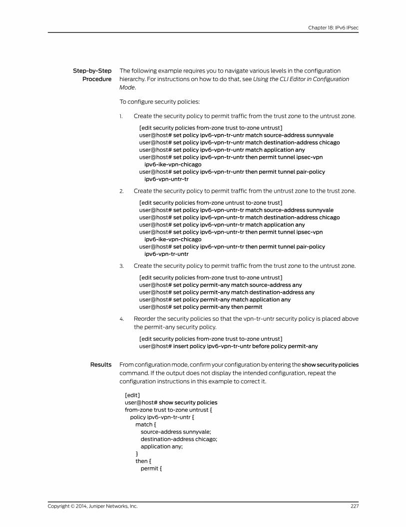
Step-by-StepProcedure
The following example requires you to navigate various levels in the configuration
hierarchy. For instructions on how to do that, see Using the CLI Editor in Configuration
Mode.
To configure security policies:
1. Create the security policy to permit traffic from the trust zone to the untrust zone.
[edit security policies from-zone trust to-zone untrust]user@host# set policy ipv6-vpn-tr-untr match source-address sunnyvaleuser@host# set policy ipv6-vpn-tr-untr match destination-address chicagouser@host# set policy ipv6-vpn-tr-untr match application anyuser@host# set policy ipv6-vpn-tr-untr then permit tunnel ipsec-vpnipv6-ike-vpn-chicago
user@host# set policy ipv6-vpn-tr-untr then permit tunnel pair-policyipv6-vpn-untr-tr
2. Create the security policy to permit traffic from the untrust zone to the trust zone.
[edit security policies from-zone untrust to-zone trust]user@host# set policy ipv6-vpn-untr-tr match source-address sunnyvaleuser@host# set policy ipv6-vpn-untr-tr match destination-address chicagouser@host# set policy ipv6-vpn-untr-tr match application anyuser@host# set policy ipv6-vpn-untr-tr then permit tunnel ipsec-vpnipv6-ike-vpn-chicago
user@host# set policy ipv6-vpn-untr-tr then permit tunnel pair-policyipv6-vpn-tr-untr
3. Create the security policy to permit traffic from the trust zone to the untrust zone.
[edit security policies from-zone trust to-zone untrust]user@host# set policy permit-anymatch source-address anyuser@host# set policy permit-anymatch destination-address anyuser@host# set policy permit-anymatch application anyuser@host# set policy permit-any then permit
4. Reorder the security policies so that the vpn-tr-untr security policy is placed above
the permit-any security policy.
[edit security policies from-zone trust to-zone untrust]user@host# insert policy ipv6-vpn-tr-untr before policy permit-any
Results From configuration mode, confirm your configuration by entering the showsecuritypolicies
command. If the output does not display the intended configuration, repeat the
configuration instructions in this example to correct it.
[edit]user@host# show security policiesfrom-zone trust to-zone untrust {policy ipv6-vpn-tr-untr {match {source-address sunnyvale;destination-address chicago;application any;
}then {permit {
227Copyright © 2014, Juniper Networks, Inc.
Chapter 18: IPv6 IPsec
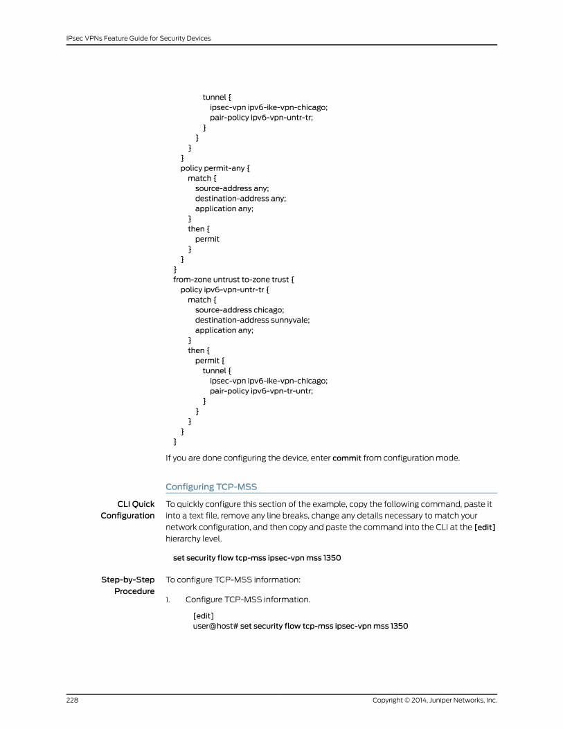
tunnel {ipsec-vpn ipv6-ike-vpn-chicago;pair-policy ipv6-vpn-untr-tr;
}}
}}policy permit-any {match {source-address any;destination-address any;application any;
}then {permit
}}
}from-zone untrust to-zone trust {policy ipv6-vpn-untr-tr {match {source-address chicago;destination-address sunnyvale;application any;
}then {permit {tunnel {ipsec-vpn ipv6-ike-vpn-chicago;pair-policy ipv6-vpn-tr-untr;
}}
}}
}
If you are done configuring the device, enter commit from configuration mode.
Configuring TCP-MSS
CLI QuickConfiguration
To quickly configure this section of the example, copy the following command, paste it
into a text file, remove any line breaks, change any details necessary to match your
network configuration, and then copy and paste the command into the CLI at the [edit]
hierarchy level.
set security flow tcp-mss ipsec-vpnmss 1350
Step-by-StepProcedure
To configure TCP-MSS information:
Configure TCP-MSS information.1.
[edit]user@host# set security flow tcp-mss ipsec-vpnmss 1350
Copyright © 2014, Juniper Networks, Inc.228
IPsec VPNs Feature Guide for Security Devices

Results From configuration mode, confirm your configuration by entering the show security flow
command. If the output does not display the intended configuration, repeat the
configuration instructions in this example to correct it.
[edit]user@host# show security flowtcp-mss {ipsec-vpn {mss 1350;
}}
If you are done configuring the device, enter commit from configuration mode.
Verification
To confirm that the configuration is working properly, perform these tasks:
• Verifying the IKE Phase 1 Status on page 229
• Verifying the IPsec Phase 2 Status on page 231
Verifying the IKE Phase 1 Status
Purpose Verify the IKE Phase 1 status.
Action NOTE: Before starting the verification process, you need to send traffic froma host in Sunnyvale to a host in Chicago. For policy-based VPNs, a separatehost must generate the traffic; traffic initiated from the SRX Series devicewill not match the VPN policy. We recommend that the test traffic be fromaseparatedeviceonone sideof theVPN toa seconddeviceon theother sideof the VPN. For example, initiate ping from 1212::abcd/64 to 1111::abcd/128.
From operational mode, enter the showsecurity ikesecurity-associationscommand. After
obtaining an index number from the command, use the show security ike
security-associations index index_number detail command.
user@host> show security ike security-associationsIndex Remote Address State Initiator cookie Responder cookie Mode5 1111::1112 UP e48efd6a444853cf 0d09c59aafb720be Aggressive
user@host> show security ike security-associations index 5 detailIKE peer 1111::1112, Index 5, Role: Initiator, State: UP Initiator cookie: e48efd6a444853cf, Responder cookie: 0d09c59aafb720be Exchange type: Aggressive, Authentication method: Pre-shared-keys Local: 1111::1111:500, Remote: 1111::1112:500 Lifetime: Expires in 19518 seconds Peer ike-id: not valid Xauth assigned IP: 0.0.0.0 Algorithms: Authentication : sha1
229Copyright © 2014, Juniper Networks, Inc.
Chapter 18: IPv6 IPsec
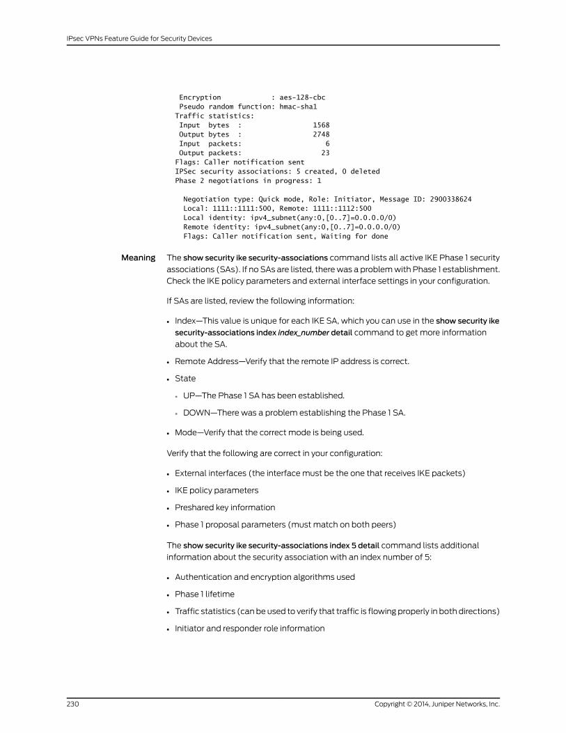
Encryption : aes-128-cbc Pseudo random function: hmac-sha1 Traffic statistics: Input bytes : 1568 Output bytes : 2748 Input packets: 6 Output packets: 23 Flags: Caller notification sent IPSec security associations: 5 created, 0 deleted Phase 2 negotiations in progress: 1
Negotiation type: Quick mode, Role: Initiator, Message ID: 2900338624 Local: 1111::1111:500, Remote: 1111::1112:500 Local identity: ipv4_subnet(any:0,[0..7]=0.0.0.0/0) Remote identity: ipv4_subnet(any:0,[0..7]=0.0.0.0/0) Flags: Caller notification sent, Waiting for done
Meaning The show security ike security-associations command lists all active IKE Phase 1 security
associations (SAs). If no SAs are listed, there was a problem with Phase 1 establishment.
Check the IKE policy parameters and external interface settings in your configuration.
If SAs are listed, review the following information:
• Index—This value is unique for each IKE SA, which you can use in the show security ike
security-associations index index_number detail command to get more information
about the SA.
• Remote Address—Verify that the remote IP address is correct.
• State
• UP—The Phase 1 SA has been established.
• DOWN—There was a problem establishing the Phase 1 SA.
• Mode—Verify that the correct mode is being used.
Verify that the following are correct in your configuration:
• External interfaces (the interface must be the one that receives IKE packets)
• IKE policy parameters
• Preshared key information
• Phase 1 proposal parameters (must match on both peers)
The show security ike security-associations index 5 detail command lists additional
information about the security association with an index number of 5:
• Authentication and encryption algorithms used
• Phase 1 lifetime
• Traffic statistics (can be used to verify that traffic is flowing properly in both directions)
• Initiator and responder role information
Copyright © 2014, Juniper Networks, Inc.230
IPsec VPNs Feature Guide for Security Devices

NOTE: Troubleshooting is best performedon the peer using the responderrole.
• Number of IPsec SAs created
• Number of Phase 2 negotiations in progress
Verifying the IPsec Phase 2 Status
Purpose Verify the IPsec Phase 2 status.
Action From operational mode, enter the show security ipsec security-associations command.
After obtaining an index number from the command, use the show security ipsec
security-associations index index_number detail command.
user@host> show security ipsec security-associations total configured sa: 2 ID Algorithm SPI Life:sec/kb Mon vsys Port Gateway 2 ESP:aes-128/sha1 14caf1d9 3597/ unlim - root 500 1111::1112 2 ESP:aes-128/sha1 9a4db486 3597/ unlim - root 500 1111::1112
user@host> show security ipsec security-associations index 2 detail Virtual-system: Root Local Gateway: 111::1111, Remote Gateway: 1111::1112 Local Identity: ipv4_subnet(any:0,[0..7]=0.0.0.0/0) Remote Identity: ipv4_subnet(any:0,[0..7]=0.0.0.0/0) DF-bit: clear Direction: inbound, SPI: 14caf1d9, AUX-SPI: 0 , VPN Monitoring: - Hard lifetime: Expires in 3440 seconds Lifesize Remaining: Unlimited Soft lifetime: Expires in 2813 seconds Mode: tunnel, Type: dynamic, State: installed Protocol: ESP, Authentication: hmac-sha1-96, Encryption: aes-cbc (128 bits) Anti-replay service: counter-based enabled, Replay window size: 64
Direction: outbound, SPI: 9a4db486, AUX-SPI: 0 , VPN Monitoring: - Hard lifetime: Expires in 3440 seconds Lifesize Remaining: Unlimited Soft lifetime: Expires in 2813 seconds Mode: tunnel, Type: dynamic, State: installed Protocol: ESP, Authentication: hmac-sha1-96, Encryption: aes-cbc (128 bits) Anti-replay service: counter-based enabled, Replay window size: 64
Meaning The output from the showsecurity ipsecsecurity-associationscommand lists the following
information:
• The ID number is 2. Use this value with the show security ipsec security-associations
index command to get more information about this particular SA.
• There is one IPsec SA pair using port 500, which indicates that no NAT-traversal is
implemented. (NAT-traversal uses port 4500 or another random high-number port.)
231Copyright © 2014, Juniper Networks, Inc.
Chapter 18: IPv6 IPsec

• The SPIs, lifetime (in seconds), and usage limits (or lifesize in KB) are shown for both
directions. The 3597/unlim value indicates that the Phase 2 lifetime expires in 3597
seconds, and that no lifesize has been specified, which indicates that the lifetime is
unlimited. Phase 2 lifetime can differ from Phase 1 lifetime, as Phase 2 is not dependent
on Phase 1 after the VPN is up.
• VPN monitoring is not enabled for this SA, as indicated by a hyphen in the Mon column.
If VPN monitoring is enabled, U (up) or D (down) is listed.
• The virtual system (vsys) is the root system, and it always lists 0.
The output from the show security ipsec security-associations index 2 detail command
lists the following information:
• The local and remote identities make up the proxy ID for the SA.
A proxy ID mismatch is one of the most common reasons for a Phase 2 failure. For
policy-based VPNs, the proxy ID is derived from the security policy. The local and remote
addresses are derived from the address book entries, and the service is derived from
the application configured for the policy. If Phase 2 fails because of a proxy ID mismatch,
you can use the policy to confirm which address book entries are configured. Verify
that the addresses match the information being sent. Check the service to ensure that
the ports match the information being sent.
NOTE: Forsomethird-partyvendors, theproxy IDmustbemanuallyenteredtomatch.
RelatedDocumentation
• Understanding IPv6 IKE and IPsec Packet Processing on page 37
• IPv6 IPsec Configuration Overview on page 213
• Example: Configuring an IPv6 IPsec Manual VPN on page 214
• IPsec VPNs Feature Guide for Security Devices
Copyright © 2014, Juniper Networks, Inc.232
IPsec VPNs Feature Guide for Security Devices

CHAPTER 19
VPN Alarms
• Example: Setting an Audible Alert as Notification of a Security Alarm on page 233
• Example: Generating Security Alarms in Response to Potential Violations on page 234
Example: Setting an Audible Alert as Notification of a Security Alarm
Supported Platforms LN Series, SRX100, SRX110, SRX210, SRX220, SRX240, SRX650
This example shows how to configure a device to generate a system alert beep when a
new security event occurs. By default, alarms are not audible.
• Requirements on page 233
• Overview on page 233
• Configuration on page 233
• Verification on page 234
Requirements
No special configuration beyond device initialization is required before configuring this
feature.
Overview
In this example, you set an audible beep to be generated in response to a security alarm.
Configuration
Step-by-StepProcedure
To set an audible alarm:
Enable security alarms.1.
[edit]user@host# edit security alarms
2. Specify that you want to be notified of security alarms with an audible beep.
[edit security alarms]user@host# set audible
3. If you are done configuring the device, commit the configuration.
[edit security alarms]user@host# commit
233Copyright © 2014, Juniper Networks, Inc.
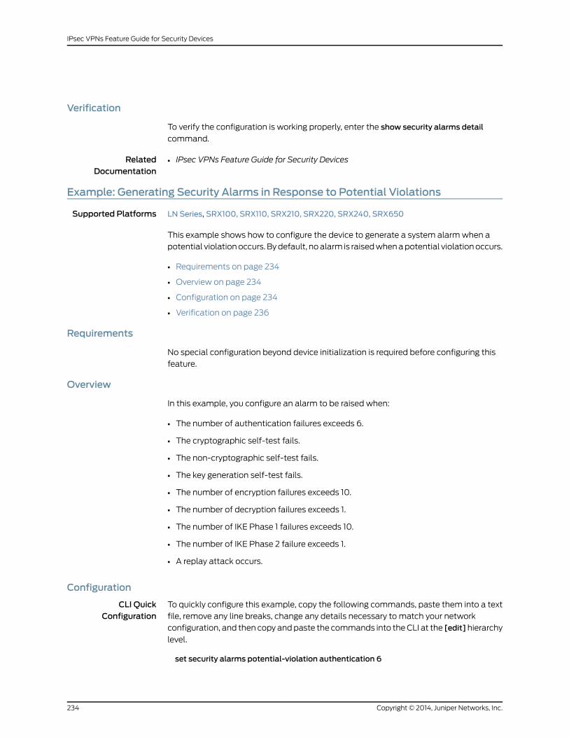
Verification
To verify the configuration is working properly, enter the show security alarms detail
command.
RelatedDocumentation
IPsec VPNs Feature Guide for Security Devices•
Example: Generating Security Alarms in Response to Potential Violations
Supported Platforms LN Series, SRX100, SRX110, SRX210, SRX220, SRX240, SRX650
This example shows how to configure the device to generate a system alarm when a
potential violation occurs. By default, no alarm is raised when a potential violation occurs.
• Requirements on page 234
• Overview on page 234
• Configuration on page 234
• Verification on page 236
Requirements
No special configuration beyond device initialization is required before configuring this
feature.
Overview
In this example, you configure an alarm to be raised when:
• The number of authentication failures exceeds 6.
• The cryptographic self-test fails.
• The non-cryptographic self-test fails.
• The key generation self-test fails.
• The number of encryption failures exceeds 10.
• The number of decryption failures exceeds 1.
• The number of IKE Phase 1 failures exceeds 10.
• The number of IKE Phase 2 failure exceeds 1.
• A replay attack occurs.
Configuration
CLI QuickConfiguration
To quickly configure this example, copy the following commands, paste them into a text
file, remove any line breaks, change any details necessary to match your network
configuration, and then copy and paste the commands into the CLI at the [edit]hierarchy
level.
set security alarms potential-violation authentication 6
Copyright © 2014, Juniper Networks, Inc.234
IPsec VPNs Feature Guide for Security Devices

set security alarms potential-violation cryptographic-self-testset security alarms potential-violation non-cryptographic-self-testset security alarms potential-violation key-generation-self-testset security alarms potential-violation encryption-failures threshold 10set security alarms potential-violation decryption-failures threshold 1set security alarms potential-violation ike-phase1-failures threshold 10set security alarms potential-violation ike-phase2-failures threshold 1set security alarms potential-violation replay-attacks
Step-by-StepProcedure
The following example requires you to navigate various levels in the configuration
hierarchy. For instructions on how to do that, see Using the CLI Editor in Configuration
Mode.
To configure alarms in response to potential violations:
1. Enable security alarms.
[edit]user@host# edit security alarms
2. Specify that an alarm should be raised when an authentication failure occurs.
[edit security alarms potential-violation]user@host# set authentication 6
3. Specify that an alarm should be raised when a cryptographic self-test failure occurs.
[edit security alarms potential-violation]user@host# set cryptographic-self-test
4. Specify that an alarm should be raised when a non-cryptographic self-test failure
occurs.
[edit security alarms potential-violation]user@host# set non-cryptographic-self-test
5. Specify that an alarm should be raised when a key generation self-test failure occurs.
[edit security alarms potential-violation]user@host# set key-generation-self-test
6. Specify that an alarm should be raised when an encryption failure occurs.
[edit security alarms potential-violation]user@host# set encryption-failures threshold 10
7. Specify that an alarm should be raised when a decryption failure occurs.
[edit security alarms potential-violation]user@host# set decryption-failures threshold 1
8. Specify that an alarm should be raised when an IKE Phase 1 failure occurs.
[edit security alarms potential-violation]user@host# set ike-phase1-failures threshold 10
9. Specify that an alarm should be raised when an IKE Phase 2 failure occurs.
[edit security alarms potential-violation]user@host# set ike-phase2-failures threshold 1
10. Specify that an alarm should be raised when a replay attack occurs.
235Copyright © 2014, Juniper Networks, Inc.
Chapter 19: VPN Alarms
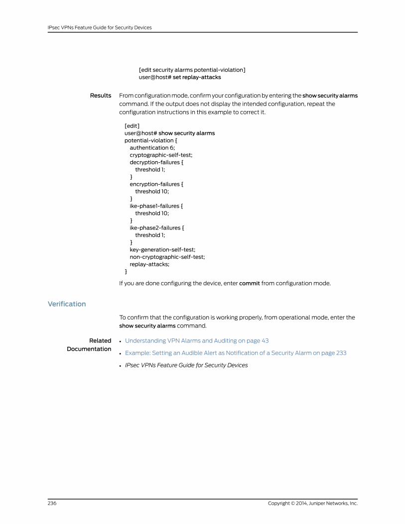
[edit security alarms potential-violation]user@host# set replay-attacks
Results From configuration mode, confirm your configuration by entering the showsecurityalarms
command. If the output does not display the intended configuration, repeat the
configuration instructions in this example to correct it.
[edit]user@host# show security alarmspotential-violation {authentication 6;cryptographic-self-test;decryption-failures {threshold 1;
}encryption-failures {threshold 10;
}ike-phase1-failures {threshold 10;
}ike-phase2-failures {threshold 1;
}key-generation-self-test;non-cryptographic-self-test;replay-attacks;
}
If you are done configuring the device, enter commit from configuration mode.
Verification
To confirm that the configuration is working properly, from operational mode, enter the
show security alarms command.
RelatedDocumentation
• Understanding VPN Alarms and Auditing on page 43
• Example: Setting an Audible Alert as Notification of a Security Alarm on page 233
• IPsec VPNs Feature Guide for Security Devices
Copyright © 2014, Juniper Networks, Inc.236
IPsec VPNs Feature Guide for Security Devices
CHAPTER 20
Global SPI and VPNMonitoring
• Example: Configuring Global SPI and VPN Monitoring Features on page 237
Example: Configuring Global SPI and VPNMonitoring Features
Supported Platforms J Series, LN Series, SRX Series
• Requirements on page 237
• Overview on page 237
• Configuration on page 237
Requirements
Before you begin, understand global SPI and VPN monitoring features. See “Understanding
Global SPI and VPN Monitoring Features” on page 45.
Overview
In this example, you configure the device to detect and respond five times to a bad IPsec
SPI before deleting the SA and initiating a new one. You also configure the device to
monitor the VPN by sending ICMP requests to the peer every 15 seconds, and to declare
the peer unreachable after 15 unsuccessful pings.
Configuration
Step-by-StepProcedure
To configure global VPN settings in the CLI editor:
Specify global VPN settings.
[edit]
1.
user@host# set security ike respond-bad-spi 5user@host# set security ipsec vpn-monitor-options interval 15 threshold 15
RelatedDocumentation
• Example: Configuring a Policy-Based VPN on page 125
• Example: Configuring a Route-Based VPN on page 61
• IPsec VPNs Feature Guide for Security Devices
237Copyright © 2014, Juniper Networks, Inc.

Copyright © 2014, Juniper Networks, Inc.238
IPsec VPNs Feature Guide for Security Devices
CHAPTER 21
VPN Session Affinity
• Enabling VPN Session Affinity on page 239
Enabling VPN Session Affinity
Supported Platforms LN Series, SRX1400, SRX3400, SRX3600, SRX5600, SRX5800
By default, VPN session affinity is disabled on SRX Series devices. Enabling VPN session
affinity can improve VPN throughput under certain conditions. This section describes
how to use the CLI to enable VPN session affinity.
Determine if clear-text sessions are being forwarded to IPsec tunnel sessions on a different
SPU. Use the show security flow session command to display session information about
clear-text sessions.
user@host> show security flow sessionFlow Sessions on FPC3 PIC0:
Session ID: 60000001, Policy name: N/A, Timeout: N/A, ValidIn: 23.0.21.11/6204 --> 23.0.21.6/41264;esp, If: ge-0/0/2.0, Pkts: 0, Bytes: 0
Session ID: 60000002, Policy name: N/A, Timeout: N/A, ValidIn: 23.0.21.11/0 --> 23.0.21.6/0;esp, If: ge-0/0/2.0, Pkts: 0, Bytes: 0
Session ID: 60000003, Policy name: self-traffic-policy/1, Timeout: 58, ValidIn: 23.0.21.6/500 --> 23.0.21.11/500;udp, If: .local..0, Pkts: 105386, Bytes: 12026528Out: 23.0.21.11/500 --> 23.0.21.6/500;udp, If: ge-0/0/2.0, Pkts: 106462, Bytes: 12105912
Session ID: 60017354, Policy name: N/A, Timeout: 1784, ValidIn: 0.0.0.0/0 --> 0.0.0.0/0;0, If: N/A, Pkts: 0, Bytes: 0Out: 26.0.20.156/23 --> 22.0.20.155/53051;tcp, If: N/A, Pkts: 0, Bytes: 0Total sessions: 4
Flow Sessions on FPC6 PIC0:
Session ID: 120000001, Policy name: N/A, Timeout: N/A, ValidIn: 23.0.21.11/0 --> 23.0.21.6/0;esp, If: ge-0/0/2.0, Pkts: 0, Bytes: 0
Session ID: 120000002, Policy name: N/A, Timeout: N/A, ValidIn: 23.0.21.11/0 --> 23.0.21.6/0;esp, If: ge-0/0/2.0, Pkts: 0, Bytes: 0
Session ID: 120031730, Policy name: default-policy-00/2, Timeout: 1764, Valid
239Copyright © 2014, Juniper Networks, Inc.

In: 22.0.20.155/53051 --> 26.0.20.156/23;tcp, If: ge-0/0/1.0, Pkts: 44, Bytes: 2399Out: 26.0.20.156/23 --> 22.0.20.155/53051;tcp, If: st0.0, Pkts: 35, Bytes: 2449Total sessions: 3
In the example, there is a tunnel session on FPC 3, PIC 0 and a clear-text session on FPC
6, PIC 0. A forwarding session (session ID 60017354) is set up on FPC 3, PIC 0.
To enable VPN session affinity:
1. In configuration mode, use the set command to enable VPN session affinity.
[edit]user@host# set security flow load-distribution session-affinity ipsec
2. Check your changes to the configuration before committing.
[edit]user@host# commit check
3. Commit the configuration.
[edit]user@host# commit
After enabling VPN session affinity, use the show security flow session command to
display session information about clear-text sessions.
user@host> show security flow sessionFlow Sessions on FPC3 PIC0:
Session ID: 60000001, Policy name: N/A, Timeout: N/A, ValidIn: 23.0.21.11/6352 --> 23.0.21.6/7927;esp, If: ge-0/0/2.0, Pkts: 0, Bytes: 0
Session ID: 60000002, Policy name: N/A, Timeout: N/A, ValidIn: 23.0.21.11/0 --> 23.0.21.6/0;esp, If: ge-0/0/2.0, Pkts: 0, Bytes: 0
Session ID: 60000003, Policy name: self-traffic-policy/1, Timeout: 56, ValidIn: 23.0.21.6/500 --> 23.0.21.11/500;udp, If: .local..0, Pkts: 105425, Bytes: 12031144Out: 23.0.21.11/500-->23.0.21.6/500;udp, If: ge-0/0/2.0,Pkts: 106503,Bytes: 12110680
Session ID: 60017387, Policy name: default-policy-00/2, Timeout: 1796, ValidIn: 22.0.20.155/53053 --> 26.0.20.156/23;tcp, If: ge-0/0/1.0, Pkts: 10, Bytes: 610Out: 26.0.20.156/23 --> 22.0.20.155/53053;tcp, If: st0.0, Pkts: 9, Bytes: 602Total sessions: 4
Flow Sessions on FPC6 PIC0:
Session ID: 120000001, Policy name: N/A, Timeout: N/A, ValidIn: 23.0.21.11/0 --> 23.0.21.6/0;esp, If: ge-0/0/2.0, Pkts: 0, Bytes: 0
Session ID: 120000002, Policy name: N/A, Timeout: N/A, ValidIn: 23.0.21.11/0 --> 23.0.21.6/0;esp, If: ge-0/0/2.0, Pkts: 0, Bytes: 0Total sessions: 2
After VPN session affinity is enabled, the clear-text session is always located on FPC 3,
PIC 0.
Copyright © 2014, Juniper Networks, Inc.240
IPsec VPNs Feature Guide for Security Devices

RelatedDocumentation
• Understanding VPN Session Affinity on page 47
• IPsec VPNs Feature Guide for Security Devices
241Copyright © 2014, Juniper Networks, Inc.
Chapter 21: VPN Session Affinity

Copyright © 2014, Juniper Networks, Inc.242
IPsec VPNs Feature Guide for Security Devices

CHAPTER 22
IKE Configuration Statements
• [edit security ike] Hierarchy Level on page 244
• address (Security IKE Gateway) on page 246
• always-send on page 246
• authentication-algorithm (Security IKE) on page 247
• authentication-method on page 248
• certificate on page 249
• connections-limit on page 250
• container on page 251
• dead-peer-detection on page 252
• dh-group (Security IKE) on page 253
• distinguished-name (Security) on page 254
• dynamic (Security) on page 255
• encryption-algorithm (Security IKE) on page 256
• external-interface (Security IKE Gateway) on page 257
• gateway (Security IKE) on page 258
• general-ikeid on page 259
• hostname on page 259
• ike (Security) on page 260
• ike (Security IPsec VPN) on page 262
• ike-policy (Security Gateway) on page 263
• ike-user-type on page 264
• inet (Security Dynamic Peer) on page 265
• inet6 (Security IKE Gateway) on page 265
• interval (Security IKE) on page 266
• lifetime-seconds (Security IKE) on page 266
• local-certificate (Security) on page 267
• local-identity on page 268
• mode (Security IKE Policy) on page 269
243Copyright © 2014, Juniper Networks, Inc.
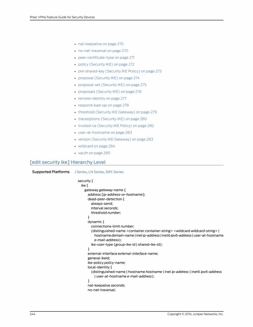
• nat-keepalive on page 270
• no-nat-traversal on page 270
• peer-certificate-type on page 271
• policy (Security IKE) on page 272
• pre-shared-key (Security IKE Policy) on page 273
• proposal (Security IKE) on page 274
• proposal-set (Security IKE) on page 275
• proposals (Security IKE) on page 276
• remote-identity on page 277
• respond-bad-spi on page 278
• threshold (Security IKE Gateway) on page 279
• traceoptions (Security IKE) on page 280
• trusted-ca (Security IKE Policy) on page 282
• user-at-hostname on page 283
• version (Security IKE Gateway) on page 283
• wildcard on page 284
• xauth on page 285
[edit security ike] Hierarchy Level
Supported Platforms J Series, LN Series, SRX Series
security {ike {gateway gateway-name {address [ip-address-or-hostname];dead-peer-detection {always-send;interval seconds;threshold number;
}dynamic {connections-limit number;(distinguished-name <container container-string> <wildcardwildcard-string> |hostnamedomain-name | inet ip-address | inet6 ipv6-address | user-at-hostnamee-mail-address);
ike-user-type (group-ike-id | shared-ike-id);}external-interface external-interface-name;general-ikeid;ike-policy policy-name;local-identity {(distinguished-name | hostname hostname | inet ip-address | inet6 ipv6-address| user-at-hostname e-mail-address);
}nat-keepalive seconds;no-nat-traversal;
Copyright © 2014, Juniper Networks, Inc.244
IPsec VPNs Feature Guide for Security Devices
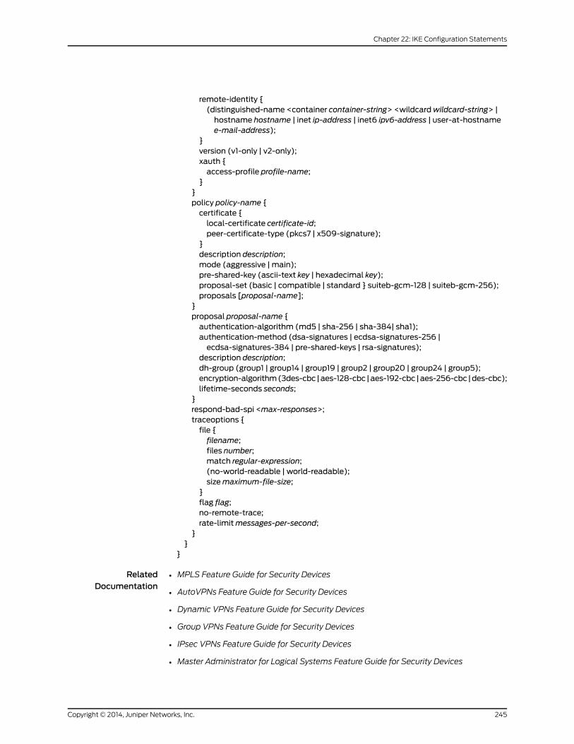
remote-identity {(distinguished-name <container container-string> <wildcardwildcard-string> |hostname hostname | inet ip-address | inet6 ipv6-address | user-at-hostnamee-mail-address);
}version (v1-only | v2-only);xauth {access-profile profile-name;
}}policy policy-name {certificate {local-certificate certificate-id;peer-certificate-type (pkcs7 | x509-signature);
}description description;mode (aggressive | main);pre-shared-key (ascii-text key | hexadecimal key);proposal-set (basic | compatible | standard } suiteb-gcm-128 | suiteb-gcm-256);proposals [proposal-name];
}proposal proposal-name {authentication-algorithm (md5 | sha-256 | sha-384| sha1);authentication-method (dsa-signatures | ecdsa-signatures-256 |ecdsa-signatures-384 | pre-shared-keys | rsa-signatures);
description description;dh-group (group1 | group14 | group19 | group2 | group20 | group24 | group5);encryption-algorithm(3des-cbc |aes-128-cbc |aes-192-cbc |aes-256-cbc |des-cbc);lifetime-seconds seconds;
}respond-bad-spi <max-responses>;traceoptions {file {filename;files number;match regular-expression;(no-world-readable | world-readable);sizemaximum-file-size;
}flag flag;no-remote-trace;rate-limitmessages-per-second;
}}
}
RelatedDocumentation
MPLS Feature Guide for Security Devices•
• AutoVPNs Feature Guide for Security Devices
• Dynamic VPNs Feature Guide for Security Devices
• Group VPNs Feature Guide for Security Devices
• IPsec VPNs Feature Guide for Security Devices
• Master Administrator for Logical Systems Feature Guide for Security Devices
245Copyright © 2014, Juniper Networks, Inc.
Chapter 22: IKE Configuration Statements
address (Security IKE Gateway)
Supported Platforms J Series, LN Series, SRX Series
Syntax address [ip-address-or-hostname];
Hierarchy Level [edit security group-vpnmember ike gateway gateway-name][edit security ike gateway gateway-name]
Release Information Statement introduced in Junos OS Release 8.5. Support for group-vpn hierarchies added
in Junos OS Release 10.2. Support for IPv6 addresses added in Junos OS Release 11.1.
Description Specify the IPv4 or IPv6 address or the hostname of the primary Internet Key Exchange
(IKE) gateway and up to four backup gateways.
Options ip-address-or-hostname—IPv4 or IPv6 address or hostname of an IKE gateway.
Required PrivilegeLevel
security—To view this statement in the configuration.
security-control—To add this statement to the configuration.
RelatedDocumentation
• AutoVPNs Feature Guide for Security Devices
always-send
Supported Platforms J Series, LN Series, SRX Series
Syntax always-send;
Hierarchy Level [edit security ike gateway gateway-name dead-peer-detection]
Release Information Statement introduced in Junos OS Release 8.5.
Description Instructs the device to send dead peer detection (DPD) requests regardless of whether
there is outgoing IPsec traffic to the peer.
Required PrivilegeLevel
security—To view this statement in the configuration.
security-control—To add this statement to the configuration.
RelatedDocumentation
• Dynamic VPNs Feature Guide for Security Devices
• Group VPNs Feature Guide for Security Devices
• IPsec VPNs Feature Guide for Security Devices
Copyright © 2014, Juniper Networks, Inc.246
IPsec VPNs Feature Guide for Security Devices
authentication-algorithm (Security IKE)
Supported Platforms J Series, LN Series, SRX Series
Syntax authentication-algorithm (md5 | sha-256 | sha-384 | sha1);
Hierarchy Level [edit security ike proposal proposal-name]
Release Information Statement introduced in Junos OS Release 8.5. Support for the sha-384 option added
in Junos OS Release 12.1X45-D10.
Description Configure the Internet Key Exchange (IKE) authentication algorithm.
NOTE: The device does not delete existing IPsec SAs when you update theauthentication-algorithmconfiguration in the IKEproposal. Thedevicedeletes
existing IPsecSAswhenyouupdatetheauthentication-algorithmconfiguration
in the IPsec proposal.
Options authentication-algorithm—Hash algorithm that authenticates packet data. It can be one
of the following algorithms:
• md5—Produces a 128-bit digest.
• sha-256—Produces a 256-bit digest. This option is not supported on group VPNs.
• sha-384—Produces a 384-bit digest. This option is not supported on group VPNs.
• sha1—Produces a 160-bit digest.
Required PrivilegeLevel
security—To view this statement in the configuration.
security-control—To add this statement to the configuration.
RelatedDocumentation
• AutoVPNs Feature Guide for Security Devices
• Dynamic VPNs Feature Guide for Security Devices
• IPsec VPNs Feature Guide for Security Devices
247Copyright © 2014, Juniper Networks, Inc.
Chapter 22: IKE Configuration Statements
authentication-method
Supported Platforms J Series, LN Series, SRX Series
Syntax authentication-method (dsa-signatures | ecdsa-signatures-256 | ecdsa-signatures-384 |pre-shared-keys | rsa-signatures);
Hierarchy Level [edit security ike proposal proposal-name]
Release Information Statement introduced in Junos OS Release 8.5. Support for ecdsa-signatures-256 and
ecdsa-signatures-384 options added in Junos OS Release 12.1X45-D10.
Description Specify the method the device uses to authenticate the source of Internet Key Exchange
(IKE) messages. The pre-shared-keys option refers to a preshared key, which is a key for
encryption and decryption that both participants must have before beginning tunnel
negotiations. The other options refer to types of digital signatures, which are certificates
that confirm the identity of the certificate holder.
NOTE: The device does not delete existing IPsec SAs when you update theauthentication-method configuration in the IKE proposal.
Options • dsa-signatures—Specify that the Digital Signature Algorithm (DSA) is used. This option
is not supported on dynamic VPNs.
• ecdsa-signatures-256—Specify that the Elliptic Curve DSA (ECDSA) using the 256-bit
elliptic curve secp256r1, as specified in the Federal Information Processing Standard
(FIPS) Digital Signature Standard (DSS) 186-3, is used. This option is not supported on
group VPNs.
• ecdsa-signatures-384—Specify that the ECDSA using the 384-bit elliptic curve
secp384r1, as specified in the FIPS DSS 186-3, is used. This option is not supported on
group VPNs.
• pre-shared-keys—Specify that a preshared key, which is a secret key shared between
the two peers, is used during authentication to identify the peers to each other. The
same key must be configured for each peer. This is the default method.
• rsa-signatures—Specify that a public key algorithm, which supports encryption and
digital signatures, is used. This option is not supported on dynamic VPNs.
Required PrivilegeLevel
security—To view this statement in the configuration.
security-control—To add this statement to the configuration.
RelatedDocumentation
• AutoVPNs Feature Guide for Security Devices
• Dynamic VPNs Feature Guide for Security Devices
• IPsec VPNs Feature Guide for Security Devices
Copyright © 2014, Juniper Networks, Inc.248
IPsec VPNs Feature Guide for Security Devices

certificate
Supported Platforms J Series, LN Series, SRX Series
Syntax certificate {local-certificate certificate-id;peer-certificate-type (pkcs7 | x509-signature);
}
Hierarchy Level [edit security group-vpnmember ike policy policy-name][edit security group-vpn server ike policy policy-name][edit security ike policy policy-name]
Release Information Statement introduced in Junos OS Release 8.5. Support for group-vpn hierarchies added
in Junos OS Release 10.2.
Description Specify usage of a digital certificate to authenticate the virtual private network (VPN)
initiator and recipient. (This statement is not supported on dynamic VPN
implementations.)
Options The remaining statements are explained separately.
Required PrivilegeLevel
security—To view this statement in the configuration.
security-control—To add this statement to the configuration.
RelatedDocumentation
• AutoVPNs Feature Guide for Security Devices
• Group VPNs Feature Guide for Security Devices
• IPsec VPNs Feature Guide for Security Devices
249Copyright © 2014, Juniper Networks, Inc.
Chapter 22: IKE Configuration Statements
connections-limit
Supported Platforms J Series, LN Series, SRX Series
Syntax connections-limit number;
Hierarchy Level [edit security ike gateway gateway-name dynamic]
Release Information Statement introduced in Junos OS Release 8.5.
Description Configure the number of concurrent connections that the group profile supports. When
the maximum number of connections is reached, no more dynamic virtual private network
(VPN) endpoints dialup users attempting to access an IPsec VPN are allowed to begin
Internet Key Exchange (IKE) negotiations.
Options number—Maximum number of concurrent connections allowed.
Required PrivilegeLevel
security—To view this statement in the configuration.
security-control—To add this statement to the configuration.
RelatedDocumentation
• IPsec VPNs Feature Guide for Security Devices
• Network Monitoring and Troubleshooting Guide for Security Devices
• System Log Monitoring and Troubleshooting Guide for Security Devices
Copyright © 2014, Juniper Networks, Inc.250
IPsec VPNs Feature Guide for Security Devices
container
Supported Platforms J Series, LN Series, SRX Series
Syntax container container-string;
Hierarchy Level [edit security group-vpn server ike gateway gateway-name dynamic distinguished-name][edit security ike gateway gateway-name dynamic distinguished-name]
Release Information Statement introduced in Junos OS Release 8.5. Support for group-vpn server hierarchy
added in Junos OS Release 10.2.
Description Specify that the value in the identity fields of a dynamic virtual private network (VPN)
endpoint user's distinguished name exactly match the values in the group IKE user's
distinguished name. The order of the identity fields in the fields of the distinguished name
strings must be identical when matching. (This statement is not supported on dynamic
VPN implementations.)
Options container-string—Distinguished name identity value to be matched. For example,
cn=admin, ou=eng, o=juniper, dc=net.
NOTE: Addaspacebetweeneach container string. For example, edit security
ike gateway jsr_gateway dynamic distinguished-name container o=juniper,
ou=eng;
Required PrivilegeLevel
security—To view this statement in the configuration.
security-control—To add this statement to the configuration.
RelatedDocumentation
• AutoVPNs Feature Guide for Security Devices
• Group VPNs Feature Guide for Security Devices
• IPsec VPNs Feature Guide for Security Devices
• Network Monitoring and Troubleshooting Guide for Security Devices
• System Log Monitoring and Troubleshooting Guide for Security Devices
251Copyright © 2014, Juniper Networks, Inc.
Chapter 22: IKE Configuration Statements
dead-peer-detection
Supported Platforms J Series, LN Series, SRX Series
Syntax dead-peer-detection {always-send;interval seconds;threshold number;
}
Hierarchy Level [edit security ike gateway gateway-name]
Release Information Statement introduced in Junos OS Release 8.5.
Description Enable the device to use dead peer detection (DPD). DPD is a method used by devices
to verify the current existence and availability of IPsec peer devices. A device performs
this verification by sending encrypted IKE Phase 1 notification payloads (R-U-THERE) to
peers and waiting for DPD acknowledgements (R-U-THERE-ACK).
Options The remaining statements are explained separately.
Required PrivilegeLevel
security—To view this statement in the configuration.
security-control—To add this statement to the configuration.
RelatedDocumentation
• AutoVPNs Feature Guide for Security Devices
• Dynamic VPNs Feature Guide for Security Devices
• Group VPNs Feature Guide for Security Devices
• IPsec VPNs Feature Guide for Security Devices
Copyright © 2014, Juniper Networks, Inc.252
IPsec VPNs Feature Guide for Security Devices

dh-group (Security IKE)
Supported Platforms J Series, LN Series, SRX Series
Syntax dh-group (group1 | group14 | group19 | group2 | group20 | group24| group5);
Hierarchy Level [edit security ike proposal proposal-name]
Release Information Statement introduced in Junos OS Release 8.5. Support for the group14 option added in
Junos OS Release 11.1. Support for group19, group20, and group24 options added in Junos
OS Release 12.1X45-D10.
Description Specify the IKE Diffie-Hellman group.
NOTE: The device does not delete existing IPsec SAs when you update thedh-group configuration in the IKE proposal.
Options dh-group—Diffie-Hellman group for key establishment.
• group1—768-bit Modular Exponential (MODP) algorithm.
• group14—2048-bit MODP group. This option is not supported on dynamic VPN
implementations.
• group19—256-bit random Elliptic Curve Groups modulo a Prime (ECP groups) algorithm.
This option is not supported on group VPN implementations.
• group2—1024-bit MODP algorithm.
• group20—384-bit random ECP groups algorithm. This option is not supported on group
VPN implementations.
• group24—2048-bit MODP Group with 256-bit prime order subgroup. This option is not
supported on group VPN implementations.
• group5—1536-bit MODP algorithm.
Required PrivilegeLevel
security—To view this statement in the configuration.
security-control—To add this statement to the configuration.
RelatedDocumentation
• AutoVPNs Feature Guide for Security Devices
• Dynamic VPNs Feature Guide for Security Devices
• IPsec VPNs Feature Guide for Security Devices
253Copyright © 2014, Juniper Networks, Inc.
Chapter 22: IKE Configuration Statements

distinguished-name (Security)
Supported Platforms J Series, LN Series, SRX Series
Syntax distinguished-name <container container-string> <wildcardwildcard-string>
Hierarchy Level [edit security group-vpn server ike gateway gateway-name][edit security ike gateway gateway-name dynamic]
Release Information Statement introduced in Junos OS Release 8.5. Support for group-vpn server hierarchy
added in Junos OS Release 10.2.
Description Specify a distinguished name as the identifier for the remote gateway with a dynamic IP
address. (This statement is not supported on dynamic VPN implementations.)
Options The remaining statements are explained separately.
Required PrivilegeLevel
security—To view this statement in the configuration.
security-control—To add this statement to the configuration.
RelatedDocumentation
• AutoVPNs Feature Guide for Security Devices
• Group VPNs Feature Guide for Security Devices
• IPsec VPNs Feature Guide for Security Devices
Copyright © 2014, Juniper Networks, Inc.254
IPsec VPNs Feature Guide for Security Devices

dynamic (Security)
Supported Platforms J Series, LN Series, SRX Series
Syntax dynamic {connections-limit number;(distinguished-name <container container-string> <wildcardwildcard-string> | hostnamedomain-name | inet ip-address | inet6 ipv6-address | user-at-hostname e-mail-address);
ike-user-type (group-ike-id | shared-ike-id);}
Hierarchy Level [edit security ike gateway gateway-name]
Release Information Statement modified in Junos OS Release 8.5. Support for the inet6option added in Junos
OS Release 11.1.
Description Specify the identifier for the remote gateway with a dynamic IPv4 or IPv6 address. Use
this statement to set up a VPN with a gateway that has an unspecified IPv4 or IPv6
address.
Options The remaining statements are explained separately.
Required PrivilegeLevel
security—To view this statement in the configuration.
security-control—To add this statement to the configuration.
RelatedDocumentation
• AutoVPNs Feature Guide for Security Devices
• Dynamic VPNs Feature Guide for Security Devices
• IPsec VPNs Feature Guide for Security Devices
255Copyright © 2014, Juniper Networks, Inc.
Chapter 22: IKE Configuration Statements

encryption-algorithm (Security IKE)
Supported Platforms J Series, LN Series, SRX Series
Syntax encryption-algorithm (3des-cbc | aes-128-cbc | aes-192-cbc | aes-256-cbc | des-cbc);
Hierarchy Level [edit security group-vpnmember ike proposal proposal-name][edit security group-vpn server ike proposal proposal-name][edit security ike proposal proposal-name]
Release Information Statement introduced in Junos OS Release 8.5. Support for group-vpn hierarchies added
in Junos OS Release 10.2.
Description Configure an encryption algorithm for an IKE proposal.
NOTE: The device does not delete existing IPsec SAs when you update theencryption-algorithm configuration in the IKE proposal.
Options • 3des-cbc—Has a block size of 24 bytes; the key size is 192 bits long.
• aes-128-cbc—Advanced Encryption Standard (AES) 128-bit encryption algorithm.
• aes-192-cbc—AES 192-bit encryption algorithm.
• aes-256-cbc—AES 256-bit encryption algorithm.
• des-cbc—Has a block size of 8 bytes; the key size is 48 bits long.
Required PrivilegeLevel
security—To view this statement in the configuration.
security-control—To add this statement to the configuration.
RelatedDocumentation
• AutoVPNs Feature Guide for Security Devices
• Dynamic VPNs Feature Guide for Security Devices
• Group VPNs Feature Guide for Security Devices
• IPsec VPNs Feature Guide for Security Devices
• Network Monitoring and Troubleshooting Guide for Security Devices
• System Log Monitoring and Troubleshooting Guide for Security Devices
Copyright © 2014, Juniper Networks, Inc.256
IPsec VPNs Feature Guide for Security Devices

external-interface (Security IKE Gateway)
Supported Platforms J Series, LN Series, SRX Series
Syntax external-interface external-interface-name;
Hierarchy Level [edit security ike gateway gateway-name]
Release Information Statement introduced in Junos OS Release 8.5.
Description Specify the outgoing interface for IKE SAs. This interface is associated with a zone that
acts as its carrier, providing firewall security for it.
Options external-interface-name —Name of the interface to be used to send traffic to the IPsec
VPN.
Required PrivilegeLevel
security—To view this statement in the configuration.
security-control—To add this statement to the configuration.
RelatedDocumentation
• AutoVPNs Feature Guide for Security Devices
• Dynamic VPNs Feature Guide for Security Devices
• IPsec VPNs Feature Guide for Security Devices
257Copyright © 2014, Juniper Networks, Inc.
Chapter 22: IKE Configuration Statements

gateway (Security IKE)
Supported Platforms J Series, LN Series, SRX Series
Syntax gateway gateway-name {address [ip-address-or-hostname];dead-peer-detection {always-send;interval seconds;threshold number;
}dynamic {connections-limit number;(distinguished-name<containercontainer-string><wildcardwildcard-string>|hostnamedomain-name | inet ip-address | inet6 ipv6-address | user-at-hostnamee-mail-address);
ike-user-type (group-ike-id | shared-ike-id);}external-interface external-interface-name;general-ikeid;ike-policy policy-name;local-identity {(distinguished-name | hostname hostname | inet ip-address | inet6 ipv6-address |user-at-hostname e-mail-address);
}nat-keepalive seconds;no-nat-traversal;remote-identity {(distinguished-name<containercontainer-string><wildcardwildcard-string>|hostnamehostname | inet ip-address | inet6 ipv6-address | user-at-hostname e-mail-address);
}version (v1-only | v2-only);xauth {access-profile profile-name;
}}
Hierarchy Level [edit security ike]
Release Information Statement introduced in Junos OS Release 8.5. Support for IPv6 addresses added in
Junos OS Release 11.1. The inet6 option added in Junos OS Release 11.1.
Description Configure an IKE gateway.
Options gateway-name —Name of the gateway.
The remaining statements are explained separately.
Required PrivilegeLevel
security—To view this statement in the configuration.
security-control—To add this statement to the configuration.
RelatedDocumentation
AutoVPNs Feature Guide for Security Devices•
• Dynamic VPNs Feature Guide for Security Devices
Copyright © 2014, Juniper Networks, Inc.258
IPsec VPNs Feature Guide for Security Devices

• IPsec VPNs Feature Guide for Security Devices
general-ikeid
Supported Platforms J Series, LN Series, SRX Series
Syntax general-ikeid;
Hierarchy Level [edit security ike gateway gateway-name]
Release Information Statement introduced in Junos OS Release 10.4.
Description Accept general peer IKE ID.
Required PrivilegeLevel
security—To view this statement in the configuration.
security-control—To add this statement to the configuration.
RelatedDocumentation
• IPsec VPNs Feature Guide for Security Devices
hostname
Supported Platforms J Series, LN Series, SRX Series
Syntax hostname domain-name;
Hierarchy Level [edit security group-vpn server ike gateway gateway-name dynamic][edit security ike gateway gateway-name dynamic]
Release Information Statement introduced in Junos OS Release 8.5. Support for group-vpn server hierarchy
added in Junos OS Release 10.2.
Description Unique name by which a network-attached device is known on a network.
Options domain-name—A fully qualified domain name (FQDN).
Required PrivilegeLevel
security—To view this statement in the configuration.
security-control—To add this statement to the configuration.
RelatedDocumentation
• AutoVPNs Feature Guide for Security Devices
• Dynamic VPNs Feature Guide for Security Devices
• Group VPNs Feature Guide for Security Devices
• IPsec VPNs Feature Guide for Security Devices
259Copyright © 2014, Juniper Networks, Inc.
Chapter 22: IKE Configuration Statements
ike (Security)
Supported Platforms J Series, LN Series, SRX Series
Syntax ike {gateway gateway-name {address [ip-address-or-hostname];dead-peer-detection {always-send;interval seconds;threshold number;
}dynamic {connections-limit number;(distinguished-name <container container-string> <wildcardwildcard-string> |hostname domain-name | inet ip-address | inet6 ipv6-address | user-at-hostnamee-mail-address);
ike-user-type (group-ike-id | shared-ike-id);}external-interface external-interface-name;general-ikeid;ike-policy policy-name;local-identity {(distinguished-name | hostname hostname | inet ip-address | inet6 ipv6-address |user-at-hostname e-mail-address);
}nat-keepalive seconds;no-nat-traversal;remote-identity {(distinguished-name <container container-string> <wildcardwildcard-string> |hostname hostname | inet ip-address | inet6 ipv6-address | user-at-hostnamee-mail-address);
}version (v1-only | v2-only);xauth {access-profile profile-name;
}}policy policy-name {certificate {local-certificate certificate-id;peer-certificate-type (pkcs7 | x509-signature);
}description description;mode (aggressive | main);pre-shared-key (ascii-text key | hexadecimal key);proposal-set (basic | compatible | standard } suiteb-gcm-128 | suiteb-gcm-256);proposals [proposal-name];
}proposal proposal-name {authentication-algorithm (md5 | sha-256 | sha-384| sha1);authentication-method(dsa-signatures |ecdsa-signatures-256 |ecdsa-signatures-384| pre-shared-keys | rsa-signatures);
description description;dh-group (group1 | group14 | group19 | group2 | group20 | group24 | group5);
Copyright © 2014, Juniper Networks, Inc.260
IPsec VPNs Feature Guide for Security Devices
encryption-algorithm (3des-cbc | aes-128-cbc | aes-192-cbc | aes-256-cbc | des-cbc);lifetime-seconds seconds;
}respond-bad-spi <max-responses>;traceoptions {file {filename;files number;match regular-expression;sizemaximum-file-size;(world-readable | no-world-readable);
}flag flag;no-remote-trace;rate-limitmessages-per-second;
}}
Hierarchy Level [edit security]
Release Information Statement modified in Junos OS Release 8.5. Support for IPv6 addresses added in Junos
OS Release 11.1. The inet6 option added in Junos OS Release 11.1.
Description Define Internet Key Exchange (IKE) configuration.
Options The remaining statements are explained separately.
Required PrivilegeLevel
security—To view this statement in the configuration.
security-control—To add this statement to the configuration.
RelatedDocumentation
• IKE and ESP ALG Feature Guide for Security Devices
• AutoVPNs Feature Guide for Security Devices
• Dynamic VPNs Feature Guide for Security Devices
• IPsec VPNs Feature Guide for Security Devices
• Master Administrator for Logical Systems Feature Guide for Security Devices
261Copyright © 2014, Juniper Networks, Inc.
Chapter 22: IKE Configuration Statements
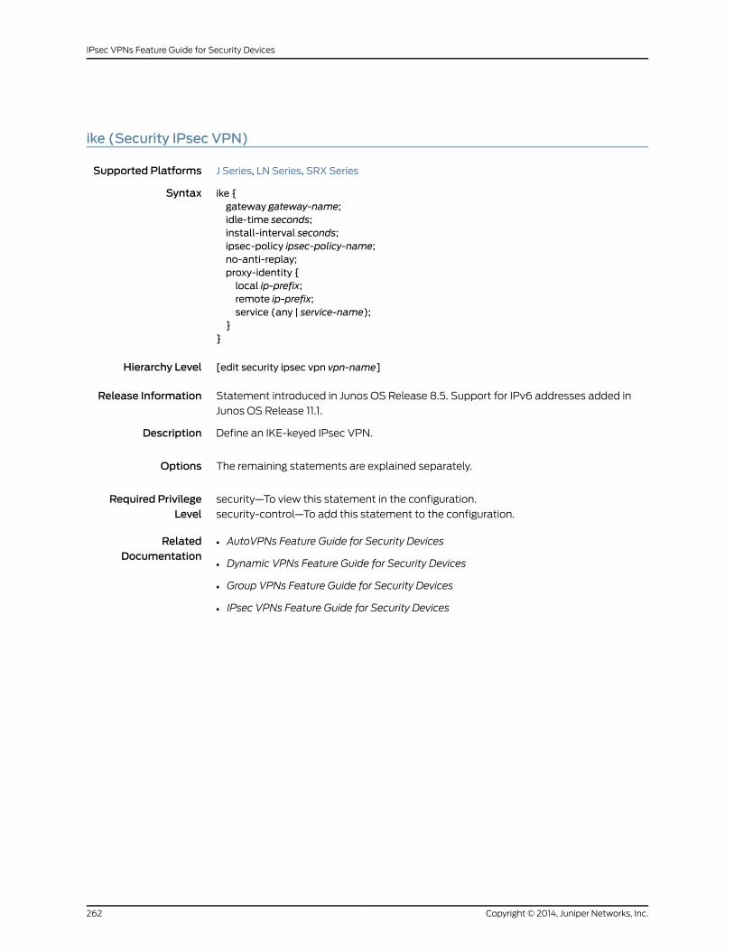
ike (Security IPsec VPN)
Supported Platforms J Series, LN Series, SRX Series
Syntax ike {gateway gateway-name;idle-time seconds;install-interval seconds;ipsec-policy ipsec-policy-name;no-anti-replay;proxy-identity {local ip-prefix;remote ip-prefix;service (any | service-name);
}}
Hierarchy Level [edit security ipsec vpn vpn-name]
Release Information Statement introduced in Junos OS Release 8.5. Support for IPv6 addresses added in
Junos OS Release 11.1.
Description Define an IKE-keyed IPsec VPN.
Options The remaining statements are explained separately.
Required PrivilegeLevel
security—To view this statement in the configuration.
security-control—To add this statement to the configuration.
RelatedDocumentation
• AutoVPNs Feature Guide for Security Devices
• Dynamic VPNs Feature Guide for Security Devices
• Group VPNs Feature Guide for Security Devices
• IPsec VPNs Feature Guide for Security Devices
Copyright © 2014, Juniper Networks, Inc.262
IPsec VPNs Feature Guide for Security Devices

ike-policy (Security Gateway)
Supported Platforms J Series, LN Series, SRX Series
Syntax ike-policy policy-name;
Hierarchy Level [edit security group-vpnmember ike gateway gateway-name][edit security group-vpn server ike gateway gateway-name][edit security ike gateway gateway-name]
Release Information Statement introduced in Junos OS Release 8.5. Support for group-vpn hierarchies added
in Junos OS Release 10.2.
Description Specify the IKE policy to be used for the gateway.
Options policy-name —IKE policy name.
Required PrivilegeLevel
security—To view this statement in the configuration.
security-control—To add this statement to the configuration.
RelatedDocumentation
• AutoVPNs Feature Guide for Security Devices
• Dynamic VPNs Feature Guide for Security Devices
• Group VPNs Feature Guide for Security Devices
• IPsec VPNs Feature Guide for Security Devices
263Copyright © 2014, Juniper Networks, Inc.
Chapter 22: IKE Configuration Statements

ike-user-type
Supported Platforms J Series, LN Series, SRX Series
Syntax ike-user-type (group-ike-id | shared-ike-id);
Hierarchy Level [edit security ike gateway gateway-name dynamic]
Release Information Statement introduced in Junos OS Release 8.5.
Description Configure the type of IKE user for a remote access connection.
Options • group-ike-id—E-mail address or fully qualified domain name (FQDN) shared for a group
of remote access users so that each one does not need a separate IKE profile configured.
• shared-ike-id—E-mail address shared for a large number of remote access users so
that each one does not need a separate IKE profile configured.
Required PrivilegeLevel
security—To view this statement in the configuration.
security-control—To add this statement to the configuration.
RelatedDocumentation
• AutoVPNs Feature Guide for Security Devices
• Dynamic VPNs Feature Guide for Security Devices
• Group VPNs Feature Guide for Security Devices
• IPsec VPNs Feature Guide for Security Devices
Copyright © 2014, Juniper Networks, Inc.264
IPsec VPNs Feature Guide for Security Devices
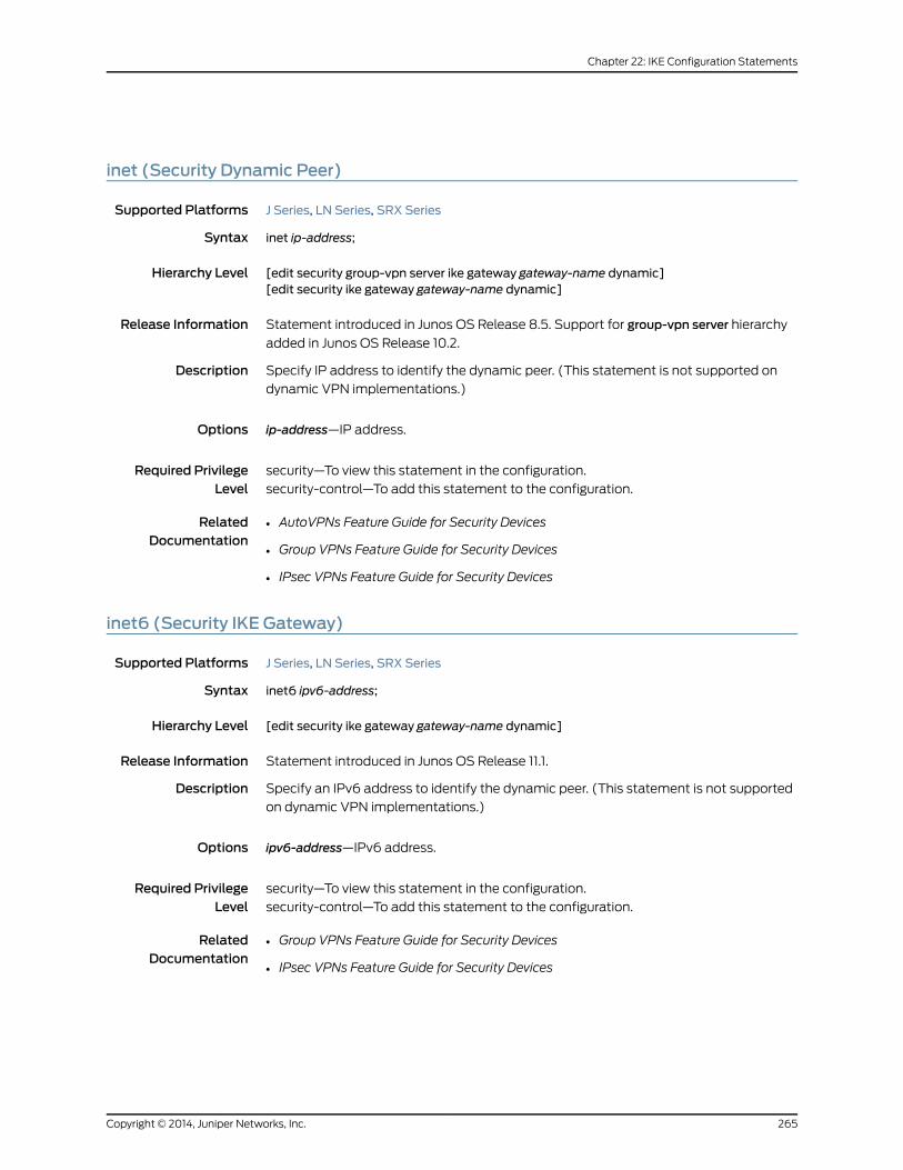
inet (Security Dynamic Peer)
Supported Platforms J Series, LN Series, SRX Series
Syntax inet ip-address;
Hierarchy Level [edit security group-vpn server ike gateway gateway-name dynamic][edit security ike gateway gateway-name dynamic]
Release Information Statement introduced in Junos OS Release 8.5. Support for group-vpn server hierarchy
added in Junos OS Release 10.2.
Description Specify IP address to identify the dynamic peer. (This statement is not supported on
dynamic VPN implementations.)
Options ip-address—IP address.
Required PrivilegeLevel
security—To view this statement in the configuration.
security-control—To add this statement to the configuration.
RelatedDocumentation
• AutoVPNs Feature Guide for Security Devices
• Group VPNs Feature Guide for Security Devices
• IPsec VPNs Feature Guide for Security Devices
inet6 (Security IKE Gateway)
Supported Platforms J Series, LN Series, SRX Series
Syntax inet6 ipv6-address;
Hierarchy Level [edit security ike gateway gateway-name dynamic]
Release Information Statement introduced in Junos OS Release 11.1.
Description Specify an IPv6 address to identify the dynamic peer. (This statement is not supported
on dynamic VPN implementations.)
Options ipv6-address—IPv6 address.
Required PrivilegeLevel
security—To view this statement in the configuration.
security-control—To add this statement to the configuration.
RelatedDocumentation
• Group VPNs Feature Guide for Security Devices
• IPsec VPNs Feature Guide for Security Devices
265Copyright © 2014, Juniper Networks, Inc.
Chapter 22: IKE Configuration Statements

interval (Security IKE)
Supported Platforms J Series, LN Series, SRX Series
Syntax interval seconds;
Hierarchy Level [edit security ike gateway gateway-name dead-peer-detection]
Release Information Statement introduced in Junos OS Release 8.5.
Description Specify the amount of time that the peer waits for traffic from its destination peer before
sending a dead-peer-detection (DPD) request packet.
Options seconds —Number of seconds that the peer waits before sending a DPD request packet.
Range: 0 through 60 seconds
Default: 10 seconds
Required PrivilegeLevel
security—To view this statement in the configuration.
security-control—To add this statement to the configuration.
RelatedDocumentation
• IPsec VPNs Feature Guide for Security Devices
lifetime-seconds (Security IKE)
Supported Platforms J Series, LN Series, SRX Series
Syntax lifetime-seconds seconds;
Hierarchy Level [edit security ike proposal proposal-name]
Release Information Statement introduced in Junos OS Release 8.5. Default value modified in Junos OS
Release 10.2.
Description Specify the lifetime (in seconds) of an IKE security association (SA). When the SA expires,
it is replaced by a new SA and security parameter index (SPI) or terminated.
Options seconds—Lifetime of the IKE SA.
Range: 180 through 86,400 seconds
Default: 28,800 seconds
Required PrivilegeLevel
security—To view this statement in the configuration.
security-control—To add this statement to the configuration.
RelatedDocumentation
• IPsec VPNs Feature Guide for Security Devices
• Infranet Authentication Feature Guide for Security Devices
Copyright © 2014, Juniper Networks, Inc.266
IPsec VPNs Feature Guide for Security Devices

local-certificate (Security)
Supported Platforms J Series, LN Series, SRX Series
Syntax local-certificate certificate-id;
Hierarchy Level [edit security group-vpnmember ike policy policy-name certificate][edit security group-vpn server ike policy policy-name certificate][edit security ike policy policy-name certificate]
Release Information Statement modified in Junos OS Release 8.5. Support for group-vpn hierarchies added
in Junos OS Release 10.2.
Description Specify a particular certificate when the local device has multiple loaded certificates.
(This statement is not supported on dynamic VPN implementations.)
NOTE: The device deletes existing IKE and IPsec SAs when you update thelocal-certificate configuration in the IKE policy.
Options certificate-id —Name of the specific certificate to be used.
Required PrivilegeLevel
security—To view this statement in the configuration.
security-control—To add this statement to the configuration.
RelatedDocumentation
• AutoVPNs Feature Guide for Security Devices
• Group VPNs Feature Guide for Security Devices
• IPsec VPNs Feature Guide for Security Devices
267Copyright © 2014, Juniper Networks, Inc.
Chapter 22: IKE Configuration Statements
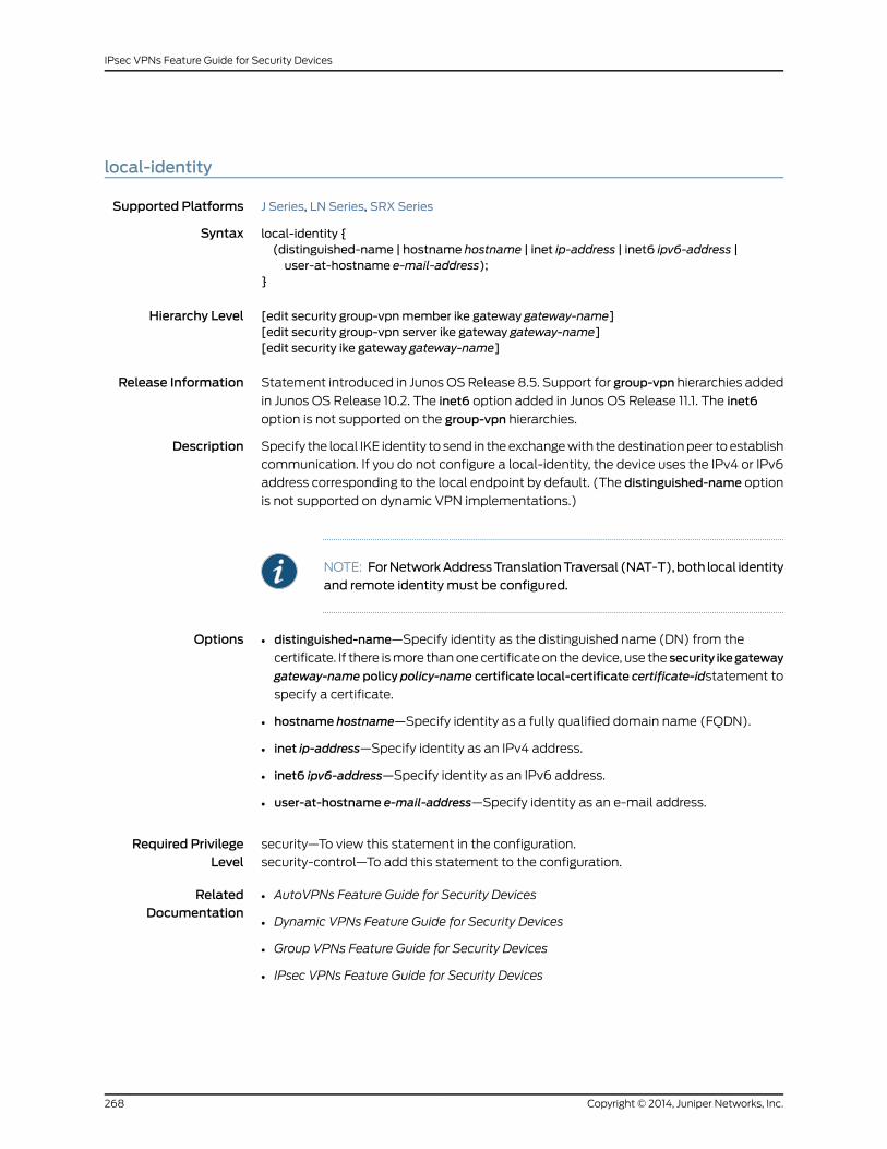
local-identity
Supported Platforms J Series, LN Series, SRX Series
Syntax local-identity {(distinguished-name | hostname hostname | inet ip-address | inet6 ipv6-address |user-at-hostname e-mail-address);
}
Hierarchy Level [edit security group-vpnmember ike gateway gateway-name][edit security group-vpn server ike gateway gateway-name][edit security ike gateway gateway-name]
Release Information Statement introduced in Junos OS Release 8.5. Support for group-vpn hierarchies added
in Junos OS Release 10.2. The inet6 option added in Junos OS Release 11.1. The inet6
option is not supported on the group-vpn hierarchies.
Description Specify the local IKE identity to send in the exchange with the destination peer to establish
communication. If you do not configure a local-identity, the device uses the IPv4 or IPv6
address corresponding to the local endpoint by default. (The distinguished-name option
is not supported on dynamic VPN implementations.)
NOTE: ForNetworkAddressTranslationTraversal (NAT-T),both local identityand remote identity must be configured.
Options • distinguished-name—Specify identity as the distinguished name (DN) from the
certificate. If there is more than one certificate on the device, use the security ikegateway
gateway-name policy policy-name certificate local-certificate certificate-idstatement to
specify a certificate.
• hostname hostname—Specify identity as a fully qualified domain name (FQDN).
• inet ip-address—Specify identity as an IPv4 address.
• inet6 ipv6-address—Specify identity as an IPv6 address.
• user-at-hostname e-mail-address—Specify identity as an e-mail address.
Required PrivilegeLevel
security—To view this statement in the configuration.
security-control—To add this statement to the configuration.
RelatedDocumentation
• AutoVPNs Feature Guide for Security Devices
• Dynamic VPNs Feature Guide for Security Devices
• Group VPNs Feature Guide for Security Devices
• IPsec VPNs Feature Guide for Security Devices
Copyright © 2014, Juniper Networks, Inc.268
IPsec VPNs Feature Guide for Security Devices

mode (Security IKE Policy)
Supported Platforms J Series, LN Series, SRX Series
Syntax mode (aggressive | main);
Hierarchy Level [edit security group-vpnmember ike policy policy-name][edit security group-vpn server ike policy policy-name][edit security ike policy policy-name]
Release Information Statement introduced in Junos OS Release 8.5. Support for group-vpn hierarchies added
in Junos OS Release 10.2.
Description Define the mode used for Internet Key Exchange (IKE) Phase 1 negotiations. Use aggressive
mode only when you need to initiate an IKE key exchange without ID protection, as when
a peer unit has a dynamically assigned IP address. (The main option is not supported on
dynamic VPN implementations.)
NOTE:
• IKEv2 protocol does not negotiate usingmode configuration.
• The device deletes existing IKE and IPsec SAs when you update themode
configuration in the IKE policy.
Options • aggressive—Aggressive mode.
• main—Main mode. Main mode is the recommended key-exchange method because it
conceals the identities of the parties during the key exchange.
Required PrivilegeLevel
security—To view this statement in the configuration.
security-control—To add this statement to the configuration.
RelatedDocumentation
• AutoVPNs Feature Guide for Security Devices
• Dynamic VPNs Feature Guide for Security Devices
• Group VPNs Feature Guide for Security Devices
• IPsec VPNs Feature Guide for Security Devices
269Copyright © 2014, Juniper Networks, Inc.
Chapter 22: IKE Configuration Statements

nat-keepalive
Supported Platforms J Series, LN Series, SRX Series
Syntax nat-keepalive seconds;
Hierarchy Level [edit security ike gateway gateway-name]
Release Information Statement introduced in Junos OS Release 8.5.
Description Specify the interval at which NAT keepalive packets can be sent so that NAT translation
continues.
Options seconds —Maximum interval in seconds at which NAT keepalive packets can be sent.
Range: 1 through 300 seconds
Default: 5 seconds
Required PrivilegeLevel
security—To view this statement in the configuration.
security-control—To add this statement to the configuration.
RelatedDocumentation
• IPsec VPNs Feature Guide for Security Devices
no-nat-traversal
Supported Platforms J Series, LN Series, SRX Series
Syntax no-nat-traversal;
Hierarchy Level [edit security ike gateway gateway-name]
Release Information Statement introduced in Junos OS Release 8.5.
Description Disables UDP encapsulation of IPsec Encapsulating Security Payload (ESP) packets,
otherwise known as Network Address Translation Traversal (NAT-T). NAT-T is enabled
by default.
Required PrivilegeLevel
security—To view this statement in the configuration.
security-control—To add this statement to the configuration.
RelatedDocumentation
• IPsec VPNs Feature Guide for Security Devices
Copyright © 2014, Juniper Networks, Inc.270
IPsec VPNs Feature Guide for Security Devices
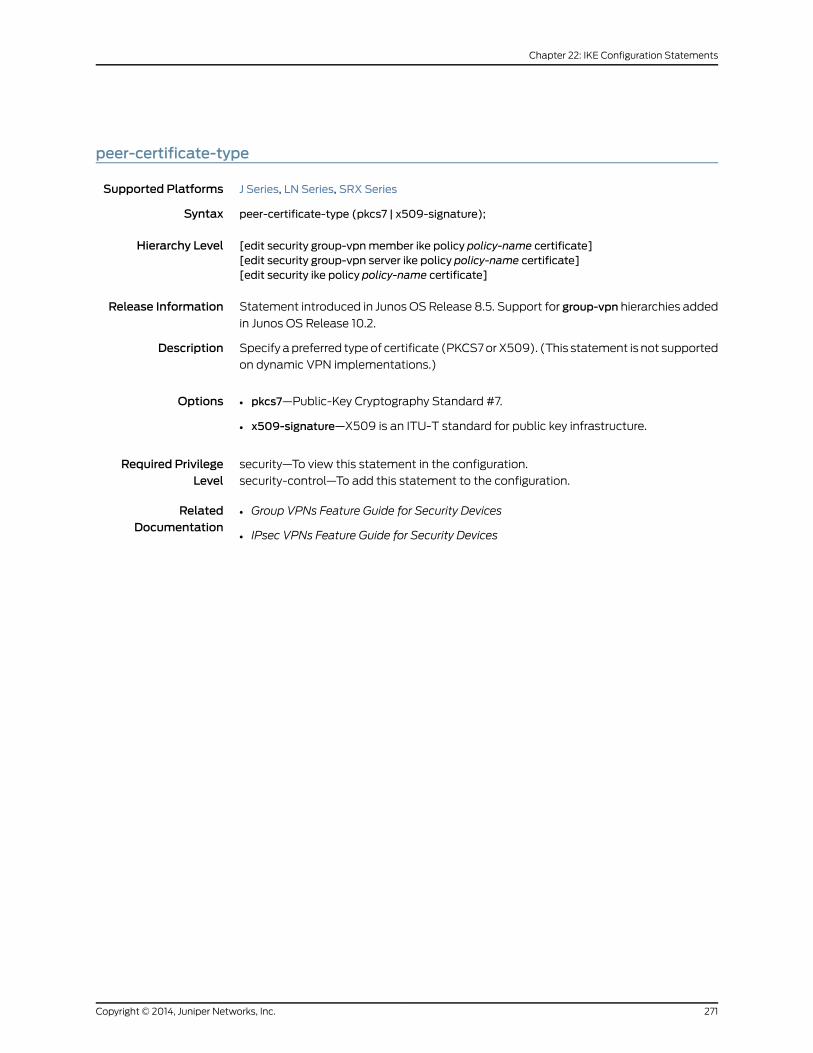
peer-certificate-type
Supported Platforms J Series, LN Series, SRX Series
Syntax peer-certificate-type (pkcs7 | x509-signature);
Hierarchy Level [edit security group-vpnmember ike policy policy-name certificate][edit security group-vpn server ike policy policy-name certificate][edit security ike policy policy-name certificate]
Release Information Statement introduced in Junos OS Release 8.5. Support for group-vpn hierarchies added
in Junos OS Release 10.2.
Description Specify a preferred type of certificate (PKCS7 or X509). (This statement is not supported
on dynamic VPN implementations.)
Options • pkcs7—Public-Key Cryptography Standard #7.
• x509-signature—X509 is an ITU-T standard for public key infrastructure.
Required PrivilegeLevel
security—To view this statement in the configuration.
security-control—To add this statement to the configuration.
RelatedDocumentation
• Group VPNs Feature Guide for Security Devices
• IPsec VPNs Feature Guide for Security Devices
271Copyright © 2014, Juniper Networks, Inc.
Chapter 22: IKE Configuration Statements

policy (Security IKE)
Supported Platforms J Series, LN Series, SRX Series
Syntax policy policy-name {certificate {local-certificate certificate-id;peer-certificate-type (pkcs7 | x509-signature);
}description description;mode (aggressive | main);pre-shared-key (ascii-text key | hexadecimal key);proposal-set (basic | compatible | standard } suiteb-gcm-128 | suiteb-gcm-256);proposals [proposal-name];
}
Hierarchy Level [edit security ike]
Release Information Statement modified in Junos OS Release 8.5. Support for suiteb-gcm-128 and
suiteb-gcm-256 options added in Junos OS Release 12.1X45-D10.
Description Configure an IKE policy.
Options policy-name—Name of the IKE policy. The policy name can be up to 32 alphanumeric
characters long.
The remaining statements are explained separately.
Required PrivilegeLevel
security—To view this statement in the configuration.
security-control—To add this statement to the configuration.
RelatedDocumentation
• AutoVPNs Feature Guide for Security Devices
• Dynamic VPNs Feature Guide for Security Devices
• IPsec VPNs Feature Guide for Security Devices
Copyright © 2014, Juniper Networks, Inc.272
IPsec VPNs Feature Guide for Security Devices
pre-shared-key (Security IKE Policy)
Supported Platforms J Series, LN Series, SRX Series
Syntax pre-shared-key (ascii-text key | hexadecimal key);
Hierarchy Level [edit security group-vpnmember ike policy policy-name][edit security group-vpn server ike policy policy-name][edit security ike policy policy-name]
Release Information Statement modified in Junos OS Release 8.5. Support for group-vpn hierarchies added
in Junos OS Release 10.2.
Description Define a preshared key for an IKE policy.
NOTE: The device deletes existing IKE and IPsec SAs when you update thepre-shared-key configuration in the IKE policy.
Options • ascii-text key—ASCII text key.
• hexadecimal key—Hexadecimal key.
Required PrivilegeLevel
security—To view this statement in the configuration.
security-control—To add this statement to the configuration.
RelatedDocumentation
• Group VPNs Feature Guide for Security Devices
• IPsec VPNs Feature Guide for Security Devices
273Copyright © 2014, Juniper Networks, Inc.
Chapter 22: IKE Configuration Statements

proposal (Security IKE)
Supported Platforms J Series, LN Series, SRX Series
Syntax proposal proposal-name {authentication-algorithm (md5 | sha-256 | sha-384| sha1);authentication-method (dsa-signatures | ecdsa-signatures-256 | ecdsa-signatures-384| pre-shared-keys | rsa-signatures);
description description;dh-group (group1 | group14 | group19 | group2 | group20 | group24 | group5);encryption-algorithm (3des-cbc | aes-128-cbc | aes-192-cbc | aes-256-cbc | des-cbc);lifetime-seconds seconds;
}
Hierarchy Level [edit security ike]
Release Information Statement modified in Junos OS Release 8.5. Support for dh-group group 14 and
dsa-signaturesadded in Junos OS Release 11.1. Support for sha-384, ecdsa-signatures-256,
ecdsa-signatures-384,group19,group20, andgroup24options added in Junos OS Release
12.1X45-D10.
Description Define an IKE proposal.
Options proposal-name—Name of the IKE proposal. The proposal name can be up to 32
alphanumeric characters long.
The remaining statements are explained separately.
Required PrivilegeLevel
security—To view this statement in the configuration.
security-control—To add this statement to the configuration.
RelatedDocumentation
• AutoVPNs Feature Guide for Security Devices
• Dynamic VPNs Feature Guide for Security Devices
• IPsec VPNs Feature Guide for Security Devices
Copyright © 2014, Juniper Networks, Inc.274
IPsec VPNs Feature Guide for Security Devices
proposal-set (Security IKE)
Supported Platforms J Series, LN Series, SRX Series
Syntax proposal-set (basic | compatible | standard | suiteb-gcm-128 | suiteb-gcm-256);
Hierarchy Level [edit security ike policy policy-name]
Release Information Statement introduced in Junos OS Release 8.5. Support for suiteb-gcm-128 and
suiteb-gcm-256 options added in Junos OS Release 12.1X45-D10.
Description Specify a set of default Internet Key Exchange (IKE) proposals.
Options basic—Basic set of two IKE proposals:•
• Proposal 1—Preshared key, Data Encryption Standard (DES) encryption, and
Diffie-Hellman (DH) group 1 and Secure Hash Algorithm 1 (SHA-1) authentication.
• Proposal 2—Preshared key, DES encryption, and DH group 1 and Message Digest 5
(MD5) authentication.
• compatible—Set of four commonly used IKE proposals:
• Proposal 1—Preshared key, triple DES (3DES) encryption, and Gnutella2 (G2) and
SHA-1 authentication.
• Proposal 2—Preshared key, 3DES encryption, and DH group 2 and MD5 authentication.
• Proposal 3—Preshared key, DES encryption, and DH group 2 and SHA-1 authentication.
• Proposal 4—Preshared key, DES encryption, and DH group 2 and MD5 authentication.
• standard—Standard set of two IKE proposals:
• Proposal 1— Preshared key, 3DES encryption, and DH group 2 and SHA-1
authentication.
• Proposal 2—Preshared key, Advanced Encryption Standard (AES) 128-bit encryption,
and DH group 2 and SHA-1 authentication.
• suiteb-gcm-128—Provides the following Suite B proposal (this option is not supported
on group VPNs):
• Authentication method—Elliptic Curve Digital Signal Algorithm (ECDSA) 256-bit
signatures
• Diffie-Hellman Group—19
• Encryption algorithm—Advanced Encryption Standard (AES) 128-bit cipher block
chaining (CBC)
NOTE: CBCmode is used instead of Galois/Counter Mode (GCM).
275Copyright © 2014, Juniper Networks, Inc.
Chapter 22: IKE Configuration Statements
• Authentication algorithm—SHA-256
• suiteb-gcm-256—Provides the following Suite B proposal (this option is not supported
on group VPNs):
• Authentication method—ECDSA 384-bit signatures
• Diffie-Hellman Group—20
• Encryption algorithm—AES 256-bit CBC
NOTE: CBCmode is used instead of GCM.
• Authentication algorithm—SHA-384
Required PrivilegeLevel
security—To view this statement in the configuration.
security-control—To add this statement to the configuration.
RelatedDocumentation
• AutoVPNs Feature Guide for Security Devices
• Dynamic VPNs Feature Guide for Security Devices
• IPsec VPNs Feature Guide for Security Devices
proposals (Security IKE)
Supported Platforms J Series, LN Series, SRX Series
Syntax proposals [proposal-name];
Hierarchy Level [edit security group-vpnmember ike policy policy-name][edit security group-vpn server ike policy policy-name][edit security ike policy policy-name]
Release Information Statement modified in Junos OS Release 8.5. Support for group-vpn hierarchies added
in Junos OS Release 10.2.
Description Specify up to four Phase 1 proposals for an IKE policy. If you include multiple proposals,
use the same Diffie-Hellman group in all of the proposals.
Options proposal-name—Names of up to four configured Phase 1 proposals.
Required PrivilegeLevel
security—To view this statement in the configuration.
security-control—To add this statement to the configuration.
RelatedDocumentation
• AutoVPNs Feature Guide for Security Devices
• Dynamic VPNs Feature Guide for Security Devices
• Group VPNs Feature Guide for Security Devices
• IPsec VPNs Feature Guide for Security Devices
Copyright © 2014, Juniper Networks, Inc.276
IPsec VPNs Feature Guide for Security Devices
remote-identity
Supported Platforms J Series, LN Series, SRX Series
Syntax remote-identity {(distinguished-name <container container-string> <wildcardwildcard-string> | hostnamehostname | inet ip-address | inet6 ipv6-address | user-at-hostname e-mail-address);
}
Hierarchy Level [edit security ike gateway gateway-name]
Release Information Statement introduced in Junos OS Release 11.4.
Description Specify the remote IKE identity to exchange with the destination peer to establish
communication. If you do not configure a remote-identity, the device uses the IPv4 or
IPv6 address corresponding to the remote endpoint by default. (The distinguished-name
option is not supported on dynamic VPN implementations.)
NOTE: For Network Address Translation Traversal (NAT-T), both remoteidentity and local identity must be configured.
Options • distinguished-name—Specify identity as the distinguished name (DN) from the
certificate. If there is more than one certificate on the device, use the security ike
gateway gateway-name policy policy-name certificate local-certificate certificate-id.
Optional container and wildcard strings may be specified:
• container container-string—Specify a string for the container.
• wildcardwildcard-string—Specify a string for the wildcard.
• hostname hostname—Specify identity as a fully qualified domain name (FQDN).
• inet ip-address—Specify identity as an IPv4 address.
• inet6 ipv6-address—Specify identity as an IPv6 address.
• user-at-hostname e-mail-address—Specify identity as an e-mail address.
Required PrivilegeLevel
security—To view this statement in the configuration.
security-control—To add this statement to the configuration.
RelatedDocumentation
• AutoVPNs Feature Guide for Security Devices
• Dynamic VPNs Feature Guide for Security Devices
• Group VPNs Feature Guide for Security Devices
• IPsec VPNs Feature Guide for Security Devices
277Copyright © 2014, Juniper Networks, Inc.
Chapter 22: IKE Configuration Statements

respond-bad-spi
Supported Platforms J Series, LN Series, SRX Series
Syntax respond-bad-spi <max-responses>;
Hierarchy Level [edit security ike]
Release Information Statement introduced in Junos OS Release 8.5.
Description Enable response to invalid IPsec Security Parameter Index (SPI) values. If the security
associations (SAs) between two peers of an IPsec VPN become unsynchronized, the
device resets the state of a peer so that the two peers are synchronized.
Options max-responses—Number of times to respond to invalid SPI values per gateway.
Range: 1 through 30
Default: 5
Required PrivilegeLevel
security—To view this statement in the configuration.
security-control—To add this statement to the configuration.
RelatedDocumentation
• AutoVPNs Feature Guide for Security Devices
• Dynamic VPNs Feature Guide for Security Devices
• Group VPNs Feature Guide for Security Devices
• IPsec VPNs Feature Guide for Security Devices
Copyright © 2014, Juniper Networks, Inc.278
IPsec VPNs Feature Guide for Security Devices

threshold (Security IKE Gateway)
Supported Platforms J Series, LN Series, SRX Series
Syntax threshold number;
Hierarchy Level [edit security ike gateway gateway-name dead-peer-detection]
Release Information Statement introduced in Junos OS Release 8.5.
Description Specify the maximum number of unsuccessful dead peer detection (DPD) requests to
be sent before the peer is considered unavailable. (This statement is not supported on
dynamic VPN implementations.)
Options number —Maximum number of unsuccessful DPD requests to be sent.
Range: 1 through 5
Output: 5
NOTE: The threshold number for the IKEv2 protocol is predefined as 5.
Required PrivilegeLevel
security—To view this statement in the configuration.
security-control—To add this statement to the configuration.
RelatedDocumentation
• AutoVPNs Feature Guide for Security Devices
• Group VPNs Feature Guide for Security Devices
• IPsec VPNs Feature Guide for Security Devices
279Copyright © 2014, Juniper Networks, Inc.
Chapter 22: IKE Configuration Statements
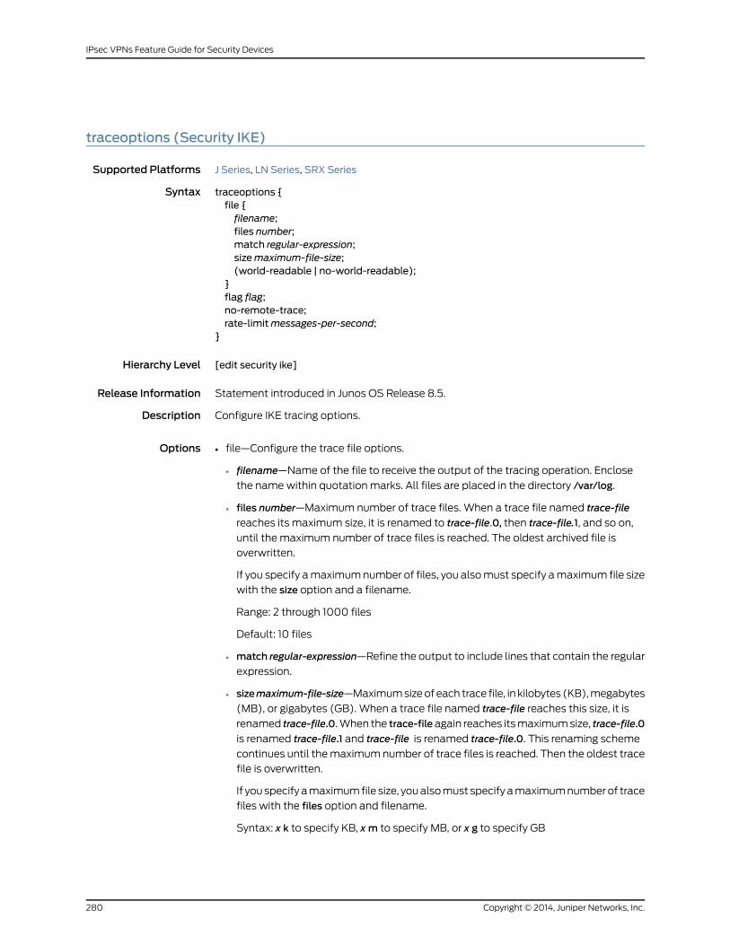
traceoptions (Security IKE)
Supported Platforms J Series, LN Series, SRX Series
Syntax traceoptions {file {filename;files number;match regular-expression;sizemaximum-file-size;(world-readable | no-world-readable);
}flag flag;no-remote-trace;rate-limitmessages-per-second;
}
Hierarchy Level [edit security ike]
Release Information Statement introduced in Junos OS Release 8.5.
Description Configure IKE tracing options.
Options file—Configure the trace file options.•
• filename—Name of the file to receive the output of the tracing operation. Enclose
the name within quotation marks. All files are placed in the directory /var/log.
• files number—Maximum number of trace files. When a trace file named trace-file
reaches its maximum size, it is renamed to trace-file.0, then trace-file.1, and so on,
until the maximum number of trace files is reached. The oldest archived file is
overwritten.
If you specify a maximum number of files, you also must specify a maximum file size
with the size option and a filename.
Range: 2 through 1000 files
Default: 10 files
• match regular-expression—Refine the output to include lines that contain the regular
expression.
• sizemaximum-file-size—Maximum size of each trace file, in kilobytes (KB), megabytes
(MB), or gigabytes (GB). When a trace file named trace-file reaches this size, it is
renamed trace-file.0. When the trace-fileagain reaches its maximum size, trace-file.0
is renamed trace-file.1 and trace-file is renamed trace-file.0. This renaming scheme
continues until the maximum number of trace files is reached. Then the oldest trace
file is overwritten.
If you specify a maximum file size, you also must specify a maximum number of trace
files with the files option and filename.
Syntax: x k to specify KB, xm to specify MB, or x g to specify GB
Copyright © 2014, Juniper Networks, Inc.280
IPsec VPNs Feature Guide for Security Devices

Range: 10 KB through 1 GB
Default: 128 KB
• world-readable | no-world-readable—By default, log files can be accessed only by
the user who configures the tracing operation. The world-readable option enables
any user to read the file. To explicitly set the default behavior, use the
no-world-readable option.
• flag—Trace operation to perform. To specify more than one trace operation, include
multiple flag statements.
• all—Trace all iked process modules activity
• certificates—Trace certificate-related activity
• config—Trace configuration download processing
• database—Trace VPN-related database activity
• general—Trace general activity
• high-availability—Trace high-availability operations
• ike—Trace IKE protocol activity
• next-hop-tunnels—Trace next-hop tunnels operations
• parse—Trace VPN parsing activity
• policy-manager—Trace iked callback activity
• routing-socket—Trace routing socket activity
• thread—Trace thread processing
• timer—Trace timer activity
• no-remote-trace—Set remote tracing as disabled.
• rate-limitmessages-per-second—Configure the incoming rate of trace messages.
Range: 0 through 4,294,967,295
Required PrivilegeLevel
trace—To view this statement in the configuration.
trace-control—To add this statement to the configuration.
RelatedDocumentation
• AutoVPNs Feature Guide for Security Devices
• Dynamic VPNs Feature Guide for Security Devices
• Group VPNs Feature Guide for Security Devices
• IPsec VPNs Feature Guide for Security Devices
281Copyright © 2014, Juniper Networks, Inc.
Chapter 22: IKE Configuration Statements

trusted-ca (Security IKE Policy)
Supported Platforms LN Series
Syntax trusted-ca (ca-index | use-all);
Hierarchy Level [edit security group-vpnmember ike policy policy-name certificate][edit security group-vpn server ike policy policy-name certificate][edit security ike policy policy-name certificate]
Release Information Statement introduced in Junos OS Release 8.5. Support for group-vpn hierarchies added
in Junos OS Release 10.2.
Description Specify the preferred certificate authority (CA) to use when requesting a certificate from
the peer. If no value is specified, then no certificate request is sent (although incoming
certificates are still accepted). (This statement is not supported on dynamic VPN
implementations.)
Options • ca-index—Preferred certificate authority ID for the device to use.
• use-all—Device uses all configured certificate authorities.
Required PrivilegeLevel
security—To view this statement in the configuration.
security-control—To add this statement to the configuration.
RelatedDocumentation
• Group VPNs Feature Guide for Security Devices
• IPsec VPNs Feature Guide for Security Devices
Copyright © 2014, Juniper Networks, Inc.282
IPsec VPNs Feature Guide for Security Devices

user-at-hostname
Supported Platforms J Series, LN Series, SRX Series
Syntax user-at-hostname e-mail-address;
Hierarchy Level [edit security group-vpn server ike gateway gateway-name dynamic][edit security ike gateway gateway-name dynamic]
Release Information Statement introduced in Junos OS Release 8.5. Support for group-vpn server hierarchy
added in Junos OS Release 10.2.
Description Configure an e-mail address. (This statement is not supported on dynamic VPN
implementations.)
Options e-mail-address —Valid e-mail address.
Required PrivilegeLevel
security—To view this statement in the configuration.
security-control—To add this statement to the configuration.
RelatedDocumentation
• AutoVPNs Feature Guide for Security Devices
• Group VPNs Feature Guide for Security Devices
• IPsec VPNs Feature Guide for Security Devices
version (Security IKE Gateway)
Supported Platforms J Series, LN Series, SRX Series
Syntax version (v1-only | v2-only);
Hierarchy Level [edit security ike gateway gateway-name]
Release Information Statement introduced in Junos OS Release 11.3.
Description Specify the IKE version to use to initiate the connection.
Options v1-only—The connection must be initiated using IKE version 1. This is the default.
v2-only—The connection must be initiated using IKE version 2.
Required PrivilegeLevel
security—To view this statement in the configuration.
security-control—To add this statement to the configuration.
RelatedDocumentation
• Dynamic VPNs Feature Guide for Security Devices
• Group VPNs Feature Guide for Security Devices
• IPsec VPNs Feature Guide for Security Devices
283Copyright © 2014, Juniper Networks, Inc.
Chapter 22: IKE Configuration Statements
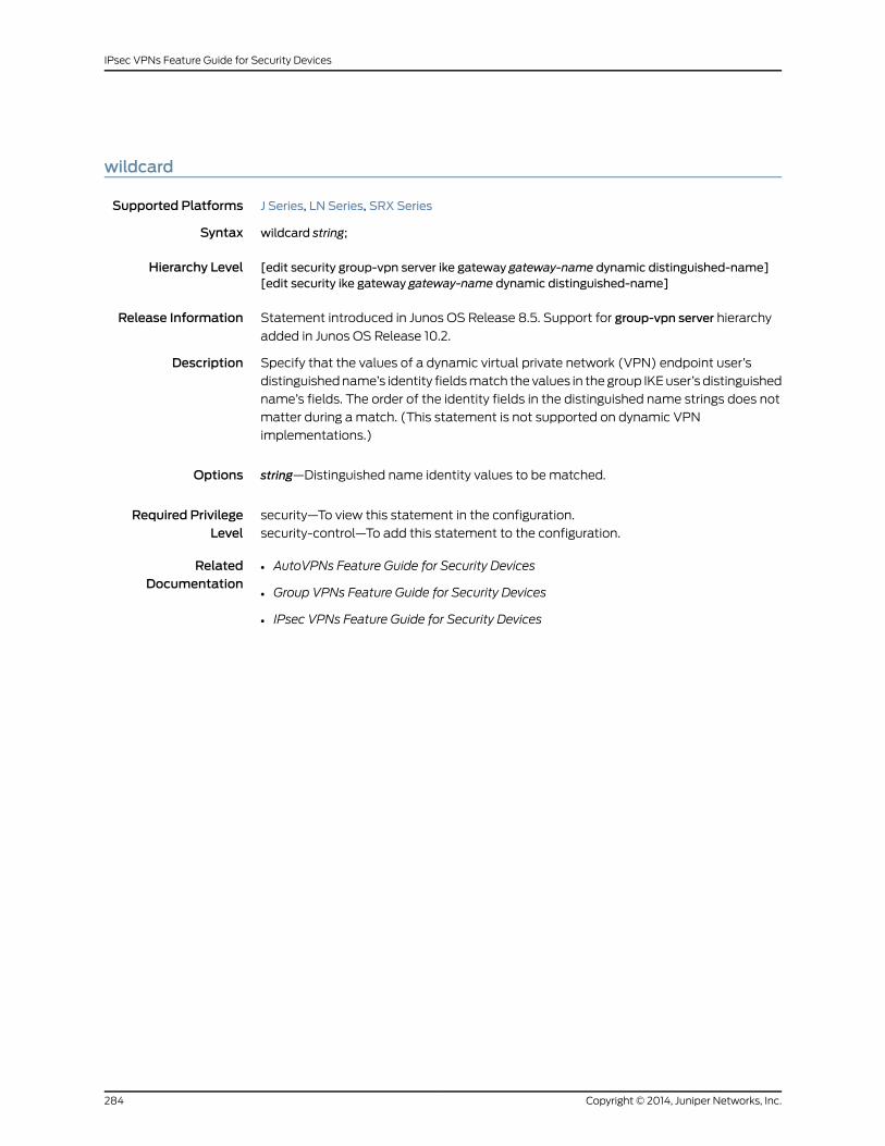
wildcard
Supported Platforms J Series, LN Series, SRX Series
Syntax wildcard string;
Hierarchy Level [edit security group-vpn server ike gateway gateway-name dynamic distinguished-name][edit security ike gateway gateway-name dynamic distinguished-name]
Release Information Statement introduced in Junos OS Release 8.5. Support for group-vpn server hierarchy
added in Junos OS Release 10.2.
Description Specify that the values of a dynamic virtual private network (VPN) endpoint user’s
distinguished name’s identity fields match the values in the group IKE user’s distinguished
name’s fields. The order of the identity fields in the distinguished name strings does not
matter during a match. (This statement is not supported on dynamic VPN
implementations.)
Options string—Distinguished name identity values to be matched.
Required PrivilegeLevel
security—To view this statement in the configuration.
security-control—To add this statement to the configuration.
RelatedDocumentation
• AutoVPNs Feature Guide for Security Devices
• Group VPNs Feature Guide for Security Devices
• IPsec VPNs Feature Guide for Security Devices
Copyright © 2014, Juniper Networks, Inc.284
IPsec VPNs Feature Guide for Security Devices

xauth
Supported Platforms J Series, LN Series, SRX Series
Syntax xauth {access-profile profile-name;
}
Hierarchy Level [edit security ike gateway gateway-name]
Release Information Statement introduced in Junos OS Release 8.5.
Description Specify that Extended authentication (XAuth) is performed in addition to IKE
authentication for remote users trying to access a VPN tunnel. Include a previously created
access profile, created with the edit accessprofile statement, to specify the access profile
to be used for authentication information.
Options access-profile profile-name—Name of previously created access profile to reference for
authentication information.
Required PrivilegeLevel
security—To view this statement in the configuration.
security-control—To add this statement to the configuration.
RelatedDocumentation
• Dynamic VPNs Feature Guide for Security Devices
• Group VPNs Feature Guide for Security Devices
• IPsec VPNs Feature Guide for Security Devices
285Copyright © 2014, Juniper Networks, Inc.
Chapter 22: IKE Configuration Statements

Copyright © 2014, Juniper Networks, Inc.286
IPsec VPNs Feature Guide for Security Devices
CHAPTER 23
IPsec Configuration Statements
• [edit security ipsec] Hierarchy Level on page 288
• algorithm (Security) on page 290
• authentication (Security IPsec) on page 291
• authentication-algorithm (Security IPsec) on page 292
• bind-interface on page 293
• destination-ip (Security IPsec) on page 293
• df-bit on page 294
• encryption (Security) on page 295
• encryption-algorithm (Security IPsec) on page 296
• establish-tunnels on page 297
• external-interface (Security Manual SA) on page 297
• gateway (Security IPsec VPN) on page 298
• gateway (Security Manual SA) on page 298
• idle-time on page 299
• ike (Security IPsec VPN) on page 300
• install-interval on page 301
• ipsec (Security) on page 302
• ipsec-policy (Security) on page 303
• ipsec-vpn (Security Flow) on page 304
• lifetime-kilobytes on page 304
• lifetime-seconds (Security IPsec) on page 305
• load-distribution on page 305
• local (Security IPsec) on page 306
• manual (Security IPsec) on page 307
• no-anti-replay (Security) on page 308
• optimized on page 308
• peer-certificate-type on page 309
• perfect-forward-secrecy (Security IPsec) on page 310
287Copyright © 2014, Juniper Networks, Inc.

• policy (Security IPsec) on page 311
• pre-shared-key (Security IKE Policy) on page 312
• proposal (Security IPsec) on page 313
• proposal-set (Security IPsec) on page 314
• proposals (Security IPsec) on page 315
• protocol (Security IPsec) on page 316
• protocol (Security IPsec Manual SA) on page 317
• proxy-identity on page 318
• remote (Security IPsec) on page 319
• service (Security IPsec) on page 319
• session-affinity on page 320
• source-interface (Security) on page 320
• spi (Security IPsec) on page 321
• traceoptions (Security IPsec) on page 322
• trusted-ca (Security IKE Policy) on page 323
• vpn (Security) on page 324
• vpn-monitor on page 325
• vpn-monitor-options on page 326
[edit security ipsec] Hierarchy Level
Supported Platforms J Series, LN Series, SRX Series
security {ipsec {internal {security-association {manual encryption {algorithm 3des-cbc;key ascii-text key;}
}}policy policy-name {description description;perfect-forward-secrecykeys (group1 | group14 |group19 |group2 |group20 |group24| group5);
proposal-set (basic | compatible | standard | suiteb-gcm-128 | suiteb-gcm-256);proposals [proposal-name];
}proposal proposal-name {authentication-algorithm (hmac-md5-96 | hmac-sha-256-128 | hmac-sha-256-96| hmac-sha1-96);
description description;encryption-algorithm (3des-cbc | aes-128-cbc | aes-128-gcm | aes-192-cbc |aes-192-gcm | aes-256-cbc | aes-256-gcm | des-cbc);
lifetime-kilobytes kilobytes;
Copyright © 2014, Juniper Networks, Inc.288
IPsec VPNs Feature Guide for Security Devices
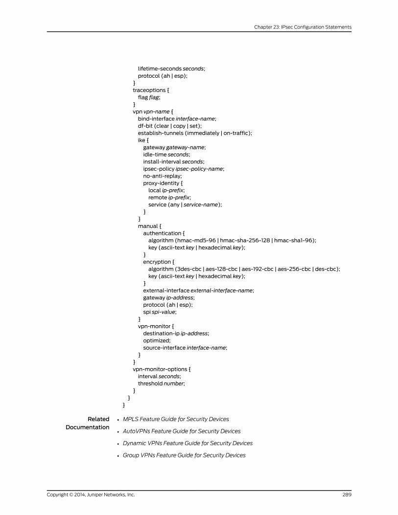
lifetime-seconds seconds;protocol (ah | esp);
}traceoptions {flag flag;
}vpn vpn-name {bind-interface interface-name;df-bit (clear | copy | set);establish-tunnels (immediately | on-traffic);ike {gateway gateway-name;idle-time seconds;install-interval seconds;ipsec-policy ipsec-policy-name;no-anti-replay;proxy-identity {local ip-prefix;remote ip-prefix;service (any | service-name);
}}manual {authentication {algorithm (hmac-md5-96 | hmac-sha-256-128 | hmac-sha1-96);key (ascii-text key | hexadecimal key);
}encryption {algorithm (3des-cbc | aes-128-cbc | aes-192-cbc | aes-256-cbc | des-cbc);key (ascii-text key | hexadecimal key);
}external-interface external-interface-name;gateway ip-address;protocol (ah | esp);spi spi-value;
}vpn-monitor {destination-ip ip-address;optimized;source-interface interface-name;
}}vpn-monitor-options {interval seconds;threshold number;
}}
}
RelatedDocumentation
MPLS Feature Guide for Security Devices•
• AutoVPNs Feature Guide for Security Devices
• Dynamic VPNs Feature Guide for Security Devices
• Group VPNs Feature Guide for Security Devices
289Copyright © 2014, Juniper Networks, Inc.
Chapter 23: IPsec Configuration Statements
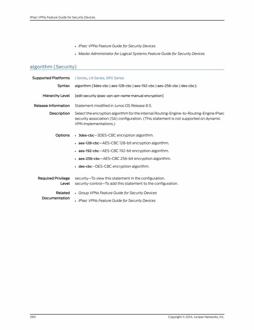
• IPsec VPNs Feature Guide for Security Devices
• Master Administrator for Logical Systems Feature Guide for Security Devices
algorithm (Security)
Supported Platforms J Series, LN Series, SRX Series
Syntax algorithm (3des-cbc | aes-128-cbc | aes-192-cbc | aes-256-cbc | des-cbc);
Hierarchy Level [edit security ipsec vpn vpn-namemanual encryption]
Release Information Statement modified in Junos OS Release 8.5.
Description Select the encryption algorithm for the internal Routing-Engine-to-Routing-Engine IPsec
security association (SA) configuration. (This statement is not supported on dynamic
VPN implementations.)
Options • 3des-cbc—3DES-CBC encryption algorithm.
• aes-128-cbc—AES-CBC 128-bit encryption algorithm.
• aes-192-cbc—AES-CBC 192-bit encryption algorithm.
• aes-256-cbc—AES-CBC 256-bit encryption algorithm.
• des-cbc—DES-CBC encryption algorithm.
Required PrivilegeLevel
security—To view this statement in the configuration.
security-control—To add this statement to the configuration.
RelatedDocumentation
• Group VPNs Feature Guide for Security Devices
• IPsec VPNs Feature Guide for Security Devices
Copyright © 2014, Juniper Networks, Inc.290
IPsec VPNs Feature Guide for Security Devices
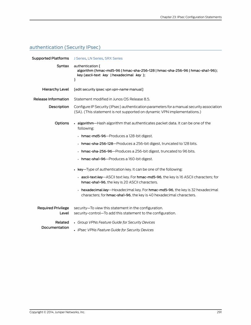
authentication (Security IPsec)
Supported Platforms J Series, LN Series, SRX Series
Syntax authentication {algorithm (hmac-md5-96 | hmac-sha-256-128 | hmac-sha-256-96 | hmac-sha1-96);key (ascii-text key | hexadecimal key );
}
Hierarchy Level [edit security ipsec vpn vpn-namemanual]
Release Information Statement modified in Junos OS Release 8.5.
Description Configure IP Security (IPsec) authentication parameters for a manual security association
(SA). (This statement is not supported on dynamic VPN implementations.)
Options • algorithm—Hash algorithm that authenticates packet data. It can be one of the
following:
• hmac-md5-96—Produces a 128-bit digest.
• hmac-sha-256-128—Produces a 256-bit digest, truncated to 128 bits.
• hmac-sha-256-96—Produces a 256-bit digest, truncated to 96 bits.
• hmac-sha1-96—Produces a 160-bit digest.
• key—Type of authentication key. It can be one of the following:
• ascii-text key—ASCII text key. For hmac-md5-96, the key is 16 ASCII characters; for
hmac-sha1-96, the key is 20 ASCII characters.
• hexadecimal key—Hexadecimal key. For hmac-md5-96, the key is 32 hexadecimal
characters; for hmac-sha1-96, the key is 40 hexadecimal characters.
Required PrivilegeLevel
security—To view this statement in the configuration.
security-control—To add this statement to the configuration.
RelatedDocumentation
• Group VPNs Feature Guide for Security Devices
• IPsec VPNs Feature Guide for Security Devices
291Copyright © 2014, Juniper Networks, Inc.
Chapter 23: IPsec Configuration Statements
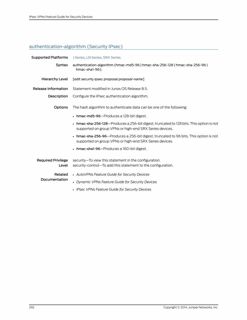
authentication-algorithm (Security IPsec)
Supported Platforms J Series, LN Series, SRX Series
Syntax authentication-algorithm (hmac-md5-96 | hmac-sha-256-128 | hmac-sha-256-96 |hmac-sha1-96);
Hierarchy Level [edit security ipsec proposal proposal-name]
Release Information Statement modified in Junos OS Release 8.5.
Description Configure the IPsec authentication algorithm.
Options The hash algorithm to authenticate data can be one of the following:
• hmac-md5-96—Produces a 128-bit digest.
• hmac-sha-256-128—Produces a 256-bit digest, truncated to 128 bits. This option is not
supported on group VPNs or high-end SRX Series devices.
• hmac-sha-256-96—Produces a 256-bit digest, truncated to 96 bits. This option is not
supported on group VPNs or high-end SRX Series devices.
• hmac-sha1-96—Produces a 160-bit digest.
Required PrivilegeLevel
security—To view this statement in the configuration.
security-control—To add this statement to the configuration.
RelatedDocumentation
• AutoVPNs Feature Guide for Security Devices
• Dynamic VPNs Feature Guide for Security Devices
• IPsec VPNs Feature Guide for Security Devices
Copyright © 2014, Juniper Networks, Inc.292
IPsec VPNs Feature Guide for Security Devices

bind-interface
Supported Platforms J Series, LN Series, SRX Series
Syntax bind-interface interface-name;
Hierarchy Level [edit security ipsec vpn vpn-name]
Release Information Statement modified in Junos OS Release 8.5.
Description Configure the tunnel interface to which the route-based virtual private network (VPN)
is bound.
Options interface-name —Tunnel interface.
Required PrivilegeLevel
security—To view this statement in the configuration.
security-control—To add this statement to the configuration.
RelatedDocumentation
• AutoVPNs Feature Guide for Security Devices
• Dynamic VPNs Feature Guide for Security Devices
• IPsec VPNs Feature Guide for Security Devices
destination-ip (Security IPsec)
Supported Platforms J Series, LN Series, SRX Series
Syntax destination-ip ip-address;
Hierarchy Level [edit security ipsec vpn vpn-name vpn-monitor]
Release Information Statement introduced in Junos OS Release 8.5.
Description Specify the destination of the Internet Control Message Protocol (ICMP) pings. If this
statement is used, the device uses the peer's gateway address by default. (This statement
is not supported on dynamic VPN implementations.)
Options ip-address—Destination IP address.
Required PrivilegeLevel
security—To view this statement in the configuration.
security-control—To add this statement to the configuration.
RelatedDocumentation
• AutoVPNs Feature Guide for Security Devices
• Group VPNs Feature Guide for Security Devices
• IPsec VPNs Feature Guide for Security Devices
293Copyright © 2014, Juniper Networks, Inc.
Chapter 23: IPsec Configuration Statements

df-bit
Supported Platforms J Series, LN Series, SRX Series
Syntax df-bit (clear | copy | set);
Hierarchy Level [edit security ipsec vpn vpn-name]
Release Information Statement introduced in Junos OS Release 8.5.
Description Specify how the device handles the Don't Fragment (DF) bit in the outer header.
Options • clear—Clear (disable) the DF bit from the outer header. This is the default.
• copy—Copy the DF bit to the outer header.
• set—Set (enable) the DF bit in the outer header.
Required PrivilegeLevel
security—To view this statement in the configuration.
security-control—To add this statement to the configuration.
RelatedDocumentation
• AutoVPNs Feature Guide for Security Devices
• Dynamic VPNs Feature Guide for Security Devices
• Group VPNs Feature Guide for Security Devices
• IPsec VPNs Feature Guide for Security Devices
Copyright © 2014, Juniper Networks, Inc.294
IPsec VPNs Feature Guide for Security Devices

encryption (Security)
Supported Platforms J Series, LN Series, SRX Series
Syntax encryption {algorithm (3des-cbc | aes-128-cbc | aes-192-cbc | aes-256-cbc | des-cbc);key (ascii-text key | hexadecimal key) ;
}
Hierarchy Level [edit security ipsec vpn vpn-namemanual]
Release Information Statement modified in Junos OS Release 8.5.
Description Configure an encryption algorithm and key for a manual Security Association (SA). (This
statement is not supported on dynamic VPN implementations.)
Options • algorithm—Type of encryption algorithm. It can be one of the following:
• des-cbc—Has a block size of 8 bytes (64 bits); its key size is 48 bits long.
• 3des-cbc—Has block size of 8 bytes (64 bits); its key size is 192 bits long
NOTE: For 3des-cbc, we recommend that the first 8 bytes be different
from the second 8 bytes, and the second 8 bytes be the same as thethird 8 bytes.
• aes-128-cbc—Advanced Encryption Standard (AES) 128-bit encryption algorithm.
• aes-192-cbc—Advanced Encryption Standard (AES) 192-bit encryption algorithm.
• aes-256-cbc—Advanced Encryption Standard (AES) 256-bit encryption algorithm.
• key—Type of encryption key. It can be one of the following:
• ascii-text key—ASCII text key. For the des-cbc option, the key contains 8 ASCII
characters; for 3des-cbc, the key contains 24 ASCII characters.
• hexadecimal key—Hexadecimal key. For the des-cbc option, the key contains 16
hexadecimal characters; for the 3des-cbc option, the key contains 48 hexadecimal
characters.
Required PrivilegeLevel
security—To view this statement in the configuration.
security-control—To add this statement to the configuration.
RelatedDocumentation
• Group VPNs Feature Guide for Security Devices
• IPsec VPNs Feature Guide for Security Devices
• Network Monitoring and Troubleshooting Guide for Security Devices
• System Log Monitoring and Troubleshooting Guide for Security Devices
295Copyright © 2014, Juniper Networks, Inc.
Chapter 23: IPsec Configuration Statements

encryption-algorithm (Security IPsec)
Supported Platforms J Series, LN Series, SRX Series
Syntax encryption-algorithm (3des-cbc | aes-128-cbc | aes-128-gcm | aes-192-cbc | aes-192-gcm |aes-256-cbc | aes-256-gcm | des-cbc);
Hierarchy Level [edit security ipsec proposal proposal-name]
Release Information Statement introduced in Junos OS Release 8.5. Support for aes-128-gcm, aes-192-gcm,
and aes-256-gcm options added in Junos OS Release 12.1X45-D10.
Description Configure an encryption algorithm.
NOTE: The device deletes existing IPsec SAs when you update theencryption-algorithm configuration in the IPsec proposal.
Options • 3des-cbc—Has a block size of 24 bytes; the key size is 192 bits long.
• aes-128-cbc—Advanced Encryption Standard (AES) 128-bit encryption algorithm.
• aes-128-gcm—AES Galois/Counter Mode (GCM) 128-bit encryption algorithm. This
option is for IPsec proposals only. This option is not supported on group VPNs.
• aes-192-cbc—AES 192-bit encryption algorithm.
• aes-192-gcm—AES GCM 192-bit encryption algorithm. This option is for IPsec proposals
only. This option is not supported on group VPNs.
• aes-256-cbc—AES 256-bit encryption algorithm.
• aes-256-gcm—AES GCM 256-bit encryption algorithm. This option is for IPsec proposals
only. This option is not supported on group VPNs.
• des-cbc—Has a block size of 8 bytes; the key size is 48 bits long.
Required PrivilegeLevel
security—To view this statement in the configuration.
security-control—To add this statement to the configuration.
RelatedDocumentation
• AutoVPNs Feature Guide for Security Devices
• Dynamic VPNs Feature Guide for Security Devices
• IPsec VPNs Feature Guide for Security Devices
• Network Monitoring and Troubleshooting Guide for Security Devices
• System Log Monitoring and Troubleshooting Guide for Security Devices
Copyright © 2014, Juniper Networks, Inc.296
IPsec VPNs Feature Guide for Security Devices

establish-tunnels
Supported Platforms J Series, LN Series, SRX Series
Syntax establish-tunnels (immediately | on-traffic);
Hierarchy Level [edit security ipsec vpn vpn-name]
Release Information Statement introduced in Junos OS Release 8.5.
Description Specify when IKE is activated: immediately after VPN information is configured and
configuration changes are committed, or only when data traffic flows. In the second case,
IKE needs to be negotiated with the peer gateway.
Options • immediately—IKE is activated immediately after VPN configuration and configuration
changes are committed.
• on-traffic—IKE is activated only when data traffic flows and must to be negotiated.
Required PrivilegeLevel
security—To view this statement in the configuration.
security-control—To add this statement to the configuration.
RelatedDocumentation
• AutoVPNs Feature Guide for Security Devices
• Dynamic VPNs Feature Guide for Security Devices
• Group VPNs Feature Guide for Security Devices
• IPsec VPNs Feature Guide for Security Devices
external-interface (Security Manual SA)
Supported Platforms J Series, LN Series, SRX Series
Syntax external-interface external-interface-name;
Hierarchy Level [edit security ipsec vpn vpn-namemanual]
Release Information Statement introduced in Junos OS Release 8.5.
Description Specify the outgoing interface for the manual SA. (This statement is not supported on
dynamic VPN implementations.)
Options external-interface-name —Name of the outgoing interface.
Required PrivilegeLevel
security—To view this statement in the configuration.
security-control—To add this statement to the configuration.
RelatedDocumentation
• Group VPNs Feature Guide for Security Devices
• IPsec VPNs Feature Guide for Security Devices
297Copyright © 2014, Juniper Networks, Inc.
Chapter 23: IPsec Configuration Statements

gateway (Security IPsec VPN)
Supported Platforms J Series, LN Series, SRX Series
Syntax gateway ip-address;
Hierarchy Level [edit security ipsec vpn vpn-name ike]
Release Information Statement introduced in Junos OS Release 8.5.
Description Specify the IP address of the peer.
Options ip-address—IP address of the peer.
Required PrivilegeLevel
security—To view this statement in the configuration.
security-control—To add this statement to the configuration.
RelatedDocumentation
• AutoVPNs Feature Guide for Security Devices
• Dynamic VPNs Feature Guide for Security Devices
• IPsec VPNs Feature Guide for Security Devices
gateway (Security Manual SA)
Supported Platforms J Series, LN Series, SRX Series
Syntax gateway ip-address;
Hierarchy Level [edit security ipsec vpn vpn-namemanual]
Release Information Statement introduced in Junos OS Release 8.5. Support for IPv6 addresses added in
Junos OS Release 11.1.
Description For a manual security association, specify the IPv4 or IPv6 address of the peer. (This
statement is not supported on dynamic VPN implementations.)
Options ip-address —IPv4 or IPv6 address of the peer.
Required PrivilegeLevel
security—To view this statement in the configuration.
security-control—To add this statement to the configuration.
RelatedDocumentation
• Group VPNs Feature Guide for Security Devices
• IPsec VPNs Feature Guide for Security Devices
Copyright © 2014, Juniper Networks, Inc.298
IPsec VPNs Feature Guide for Security Devices

idle-time
Supported Platforms J Series, LN Series, SRX Series
Syntax idle-time seconds;
Hierarchy Level [edit security ipsec vpn vpn-name ike]
Release Information Statement introduced in Junos OS Release 8.5.
Description Specify the maximum amount of idle time to delete a security association (SA).
Options seconds —Maximum amount of idle time.
Range: 60 through 999999 seconds
Default: To be disabled
Required PrivilegeLevel
security—To view this statement in the configuration.
security-control—To add this statement to the configuration.
RelatedDocumentation
• AutoVPNs Feature Guide for Security Devices
• Dynamic VPNs Feature Guide for Security Devices
• Group VPNs Feature Guide for Security Devices
• IPsec VPNs Feature Guide for Security Devices
299Copyright © 2014, Juniper Networks, Inc.
Chapter 23: IPsec Configuration Statements

ike (Security IPsec VPN)
Supported Platforms J Series, LN Series, SRX Series
Syntax ike {gateway gateway-name;idle-time seconds;install-interval seconds;ipsec-policy ipsec-policy-name;no-anti-replay;proxy-identity {local ip-prefix;remote ip-prefix;service (any | service-name);
}}
Hierarchy Level [edit security ipsec vpn vpn-name]
Release Information Statement introduced in Junos OS Release 8.5. Support for IPv6 addresses added in
Junos OS Release 11.1.
Description Define an IKE-keyed IPsec VPN.
Options The remaining statements are explained separately.
Required PrivilegeLevel
security—To view this statement in the configuration.
security-control—To add this statement to the configuration.
RelatedDocumentation
• AutoVPNs Feature Guide for Security Devices
• Dynamic VPNs Feature Guide for Security Devices
• Group VPNs Feature Guide for Security Devices
• IPsec VPNs Feature Guide for Security Devices
Copyright © 2014, Juniper Networks, Inc.300
IPsec VPNs Feature Guide for Security Devices

install-interval
Supported Platforms J Series, LN Series, SRX Series
Syntax install-interval seconds;
Hierarchy Level [edit security ipsec vpn vpn-name ike]
Release Information Statement introduced in Junos OS Release 8.5.
Description Specify the maximum number of seconds to allow for the installation of a rekeyed
outbound security association (SA) on the device.
Options seconds —Maximum amount of idle time.
Range: 0 through 10 seconds
Required PrivilegeLevel
security—To view this statement in the configuration.
security-control—To add this statement to the configuration.
RelatedDocumentation
• Group VPNs Feature Guide for Security Devices
• IPsec VPNs Feature Guide for Security Devices
301Copyright © 2014, Juniper Networks, Inc.
Chapter 23: IPsec Configuration Statements
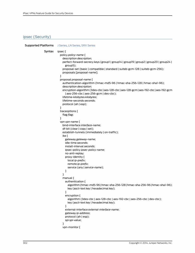
ipsec (Security)
Supported Platforms J Series, LN Series, SRX Series
Syntax ipsec {policy policy-name {description description;perfect-forward-secrecy keys (group1 | group14 | group19 | group2 | group20 | group24 |group5);
proposal-set (basic | compatible | standard | suiteb-gcm-128 | suiteb-gcm-256);proposals [proposal-name];
}proposal proposal-name {authentication-algorithm (hmac-md5-96 | hmac-sha-256-128 | hmac-sha1-96);description description;encryption-algorithm(3des-cbc |aes-128-cbc |aes-128-gcm|aes-192-cbc |aes-192-gcm| aes-256-cbc | aes-256-gcm | des-cbc);
lifetime-kilobytes kilobytes;lifetime-seconds seconds;protocol (ah | esp);
}traceoptions {flag flag;
}vpn vpn-name {bind-interface interface-name;df-bit (clear | copy | set);establish-tunnels (immediately | on-traffic);ike {gateway gateway-name;idle-time seconds;install-interval seconds;ipsec-policy ipsec-policy-name;no-anti-replay;proxy-identity {local ip-prefix;remote ip-prefix;service (any | service-name);
}}manual {authentication {algorithm(hmac-md5-96|hmac-sha-256-128|hmac-sha-256-96|hmac-sha1-96);key (ascii-text key | hexadecimal key);
}encryption {algorithm (3des-cbc | aes-128-cbc | aes-192-cbc | aes-256-cbc | des-cbc);key (ascii-text key | hexadecimal key);
}external-interface external-interface-name;gateway ip-address;protocol (ah | esp);spi spi-value;
}vpn-monitor {
Copyright © 2014, Juniper Networks, Inc.302
IPsec VPNs Feature Guide for Security Devices

destination-ip ip-address;optimized;source-interface interface-name;
}}vpn-monitor-options {interval seconds;threshold number;
}}
Hierarchy Level [edit security]
Release Information Statement modified in Junos OS Release 8.5.
Description Define IP Security (IPsec) configuration.
Options The remaining statements are explained separately.
Required PrivilegeLevel
security—To view this statement in the configuration.
security-control—To add this statement to the configuration.
RelatedDocumentation
• AutoVPNs Feature Guide for Security Devices
• Dynamic VPNs Feature Guide for Security Devices
• IPsec VPNs Feature Guide for Security Devices
• Master Administrator for Logical Systems Feature Guide for Security Devices
ipsec-policy (Security)
Supported Platforms J Series, LN Series, SRX Series
Syntax ipsec-policy ipsec-policy-name;
Hierarchy Level [edit security ipsec vpn vpn-name ike]
Release Information Statement introduced in Junos OS Release 8.5.
Description Specify the IPsec policy name.
Options ipsec-policy-name —Name of the IPsec policy.
Required PrivilegeLevel
security—To view this statement in the configuration.
security-control—To add this statement to the configuration.
RelatedDocumentation
• AutoVPNs Feature Guide for Security Devices
• Dynamic VPNs Feature Guide for Security Devices
• Group VPNs Feature Guide for Security Devices
• IPsec VPNs Feature Guide for Security Devices
303Copyright © 2014, Juniper Networks, Inc.
Chapter 23: IPsec Configuration Statements

ipsec-vpn (Security Flow)
Supported Platforms J Series, LN Series, SRX Series
Syntax ipsec-vpn {mss value;
}
Hierarchy Level [edit security flow tcp-mss]
Release Information Statement introduced in Junos OS Release 8.5.
Description Specify the TCP maximum segment size (TCP MSS) for the TCP packets that are about
to go into an IPsec VPN tunnel. This value overrides the value specified in the all-tcp-mss
statement.
Options mss value—TCP MSS value for TCP packets entering an IPsec VPN tunnel. Value is
optional.
Range: 64 through 65,535 bytes
Default: 1320 bytes
Required PrivilegeLevel
security—To view this statement in the configuration.
security-control—To add this statement to the configuration.
RelatedDocumentation
• IPsec VPNs Feature Guide for Security Devices
lifetime-kilobytes
Supported Platforms J Series, LN Series, SRX Series
Syntax lifetime-kilobytes kilobytes;
Hierarchy Level [edit security ipsec proposal proposal-name]
Release Information Statement introduced in Junos OS Release 8.5.
Description Specify the lifetime (in kilobytes) of an IPsec security association (SA).
Options kilobytes —Lifetime of the IPsec security association (SA).
Range: 64 through 1048576 kilobytes
Required PrivilegeLevel
security—To view this statement in the configuration.
security-control—To add this statement to the configuration.
RelatedDocumentation
• IPsec VPNs Feature Guide for Security Devices
Copyright © 2014, Juniper Networks, Inc.304
IPsec VPNs Feature Guide for Security Devices

lifetime-seconds (Security IPsec)
Supported Platforms J Series, LN Series, SRX Series
Syntax lifetime-seconds seconds ;
Hierarchy Level [edit security ipsec proposal proposal-name ]
Release Information Statement introduced in Junos OS Release 8.5. Default value modified in Junos OS
Release 10.2.
Description Specify the lifetime (in seconds) of an IPsec security association (SA). When the SA
expires, it is replaced by a new SA and security parameter index (SPI) or terminated.
Options seconds—Lifetime of the IPsec SA.
Range: 180 through 86,400 seconds
Default: 3600 seconds
Required PrivilegeLevel
security—To view this statement in the configuration.
security-control—To add this statement to the configuration.
RelatedDocumentation
• AutoVPNs Feature Guide for Security Devices
• Dynamic VPNs Feature Guide for Security Devices
• Group VPNs Feature Guide for Security Devices
• IPsec VPNs Feature Guide for Security Devices
load-distribution
Supported Platforms LN Series, SRX1400, SRX3400, SRX3600, SRX5600, SRX5800
Syntax load distribution {session-affinity ipsec;
}
Hierarchy Level [edit security flow]
Release Information Statement introduced in Junos OS Release 11.4R5.
Description Enable load distribution for a data flow.
Options The remaining statements are explained separately.
Required PrivilegeLevel
security—To view this statement in the configuration.
security-control—To add this statement to the configuration.
RelatedDocumentation
• IPsec VPNs Feature Guide for Security Devices
305Copyright © 2014, Juniper Networks, Inc.
Chapter 23: IPsec Configuration Statements

local (Security IPsec)
Supported Platforms J Series, LN Series, SRX Series
Syntax local ip-prefix;
Hierarchy Level [edit security ipsec vpn vpn-name ike proxy-identity]
Release Information Statement modified in Junos OS Release 8.5. Support for IPv6 addresses added in Junos
OS Release 11.1.
Description Specify the local IPv4 or IPv6 address and subnet mask for the proxy identity.
Options ip-prefix —IPv4 or IPv6 address and subnet mask.
Required PrivilegeLevel
security—To view this statement in the configuration.
security-control—To add this statement to the configuration.
RelatedDocumentation
• IPsec VPNs Feature Guide for Security Devices
Copyright © 2014, Juniper Networks, Inc.306
IPsec VPNs Feature Guide for Security Devices
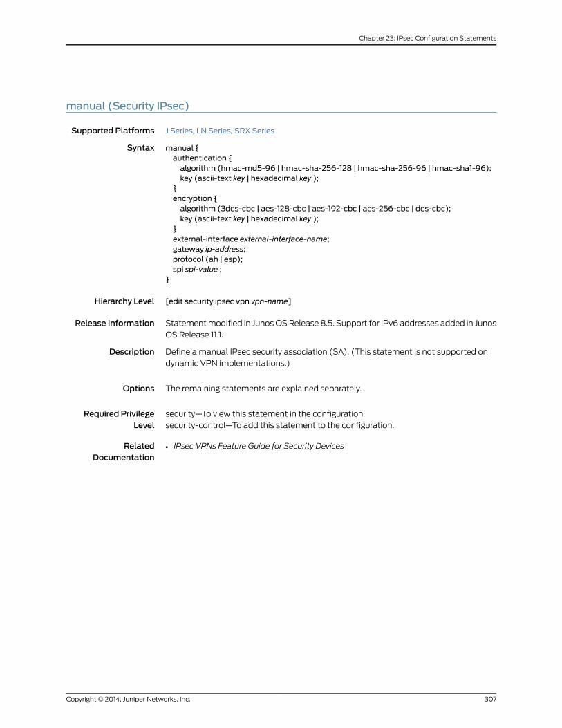
manual (Security IPsec)
Supported Platforms J Series, LN Series, SRX Series
Syntax manual {authentication {algorithm (hmac-md5-96 | hmac-sha-256-128 | hmac-sha-256-96 | hmac-sha1-96);key (ascii-text key | hexadecimal key );
}encryption {algorithm (3des-cbc | aes-128-cbc | aes-192-cbc | aes-256-cbc | des-cbc);key (ascii-text key | hexadecimal key );
}external-interface external-interface-name;gateway ip-address;protocol (ah | esp);spi spi-value ;
}
Hierarchy Level [edit security ipsec vpn vpn-name]
Release Information Statement modified in Junos OS Release 8.5. Support for IPv6 addresses added in Junos
OS Release 11.1.
Description Define a manual IPsec security association (SA). (This statement is not supported on
dynamic VPN implementations.)
Options The remaining statements are explained separately.
Required PrivilegeLevel
security—To view this statement in the configuration.
security-control—To add this statement to the configuration.
RelatedDocumentation
• IPsec VPNs Feature Guide for Security Devices
307Copyright © 2014, Juniper Networks, Inc.
Chapter 23: IPsec Configuration Statements
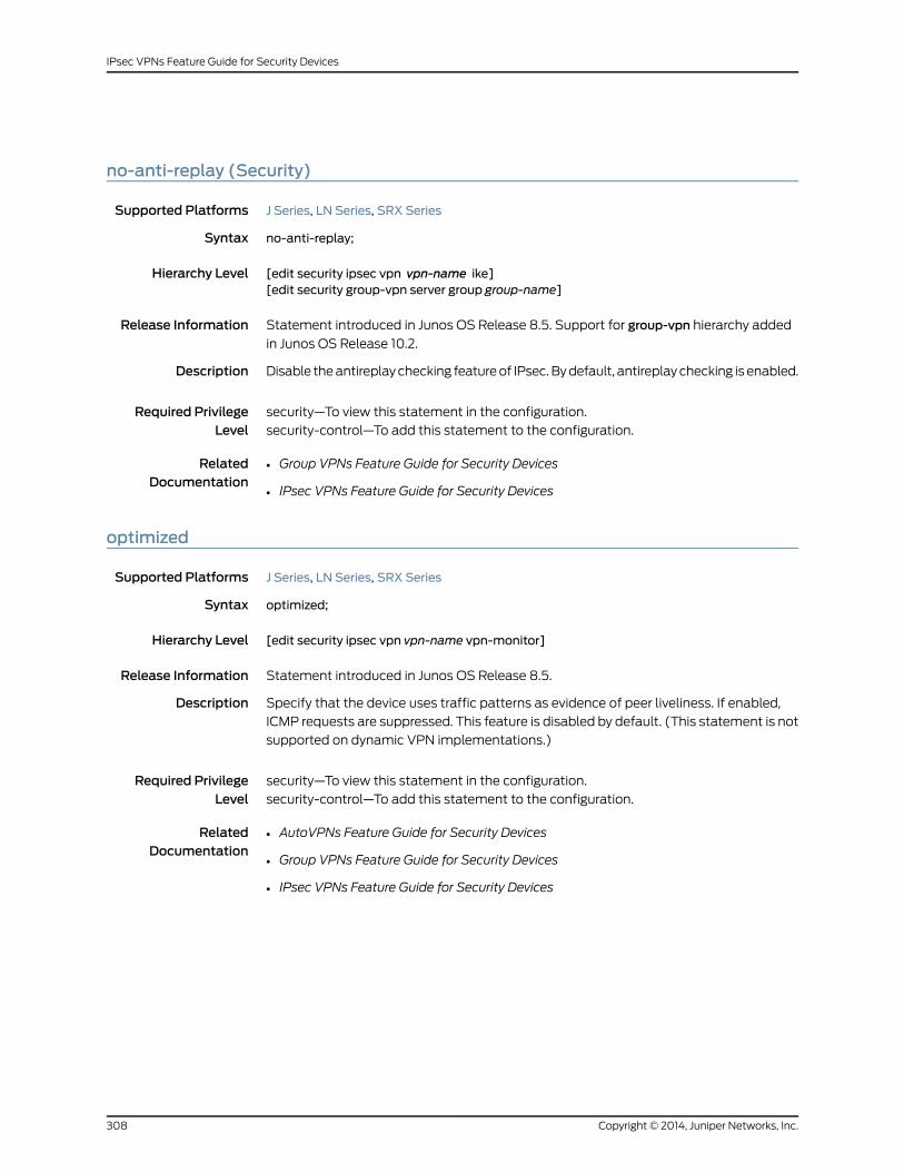
no-anti-replay (Security)
Supported Platforms J Series, LN Series, SRX Series
Syntax no-anti-replay;
Hierarchy Level [edit security ipsec vpn vpn-name ike][edit security group-vpn server group group-name]
Release Information Statement introduced in Junos OS Release 8.5. Support for group-vpn hierarchy added
in Junos OS Release 10.2.
Description Disable the antireplay checking feature of IPsec. By default, antireplay checking is enabled.
Required PrivilegeLevel
security—To view this statement in the configuration.
security-control—To add this statement to the configuration.
RelatedDocumentation
• Group VPNs Feature Guide for Security Devices
• IPsec VPNs Feature Guide for Security Devices
optimized
Supported Platforms J Series, LN Series, SRX Series
Syntax optimized;
Hierarchy Level [edit security ipsec vpn vpn-name vpn-monitor]
Release Information Statement introduced in Junos OS Release 8.5.
Description Specify that the device uses traffic patterns as evidence of peer liveliness. If enabled,
ICMP requests are suppressed. This feature is disabled by default. (This statement is not
supported on dynamic VPN implementations.)
Required PrivilegeLevel
security—To view this statement in the configuration.
security-control—To add this statement to the configuration.
RelatedDocumentation
• AutoVPNs Feature Guide for Security Devices
• Group VPNs Feature Guide for Security Devices
• IPsec VPNs Feature Guide for Security Devices
Copyright © 2014, Juniper Networks, Inc.308
IPsec VPNs Feature Guide for Security Devices

peer-certificate-type
Supported Platforms J Series, LN Series, SRX Series
Syntax peer-certificate-type (pkcs7 | x509-signature);
Hierarchy Level [edit security group-vpnmember ike policy policy-name certificate][edit security group-vpn server ike policy policy-name certificate][edit security ike policy policy-name certificate]
Release Information Statement introduced in Junos OS Release 8.5. Support for group-vpn hierarchies added
in Junos OS Release 10.2.
Description Specify a preferred type of certificate (PKCS7 or X509). (This statement is not supported
on dynamic VPN implementations.)
Options • pkcs7—Public-Key Cryptography Standard #7.
• x509-signature—X509 is an ITU-T standard for public key infrastructure.
Required PrivilegeLevel
security—To view this statement in the configuration.
security-control—To add this statement to the configuration.
RelatedDocumentation
• Group VPNs Feature Guide for Security Devices
• IPsec VPNs Feature Guide for Security Devices
309Copyright © 2014, Juniper Networks, Inc.
Chapter 23: IPsec Configuration Statements

perfect-forward-secrecy (Security IPsec)
Supported Platforms J Series, LN Series, SRX Series
Syntax perfect-forward-secrecy keys (group1 | group14 | group19 | group2 | group20 | group24 |group5);
Hierarchy Level [edit security ipsec policy policy-name]
Release Information Statement introduced in Junos OS Release 8.5. Support for group14 options added in
Junos OS Release 11.1. Support for group19, group20, and group24 options added in Junos
OS Release 12.1X45-D10.
Description Specify Perfect Forward Secrecy (PFS) as the method that the device uses to generate
the encryption key. PFS generates each new encryption key independently from the
previous key.
NOTE: The device deletes existing IPsec SAs when you update theperfect-forward-secrecy configuration in the IPsec policy.
Options • group1—Diffie-Hellman Group 1.
• group14—Diffie-Hellman Group 14. This option is not supported on dynamic VPNs.
• group19—Diffie-Hellman Group 19. This option is not supported on group VPNs.
• group2—Diffie-Hellman Group 2.
• group20—Diffie-Hellman Group 20. This option is not supported on group VPNs.
• group24—Diffie-Hellman Group 24. This option is not supported on group VPNs.
• group5—Diffie-Hellman Group 5.
Required PrivilegeLevel
security—To view this statement in the configuration.
security-control—To add this statement to the configuration.
RelatedDocumentation
• AutoVPNs Feature Guide for Security Devices
• Dynamic VPNs Feature Guide for Security Devices
• Group VPNs Feature Guide for Security Devices
• IPsec VPNs Feature Guide for Security Devices
Copyright © 2014, Juniper Networks, Inc.310
IPsec VPNs Feature Guide for Security Devices

policy (Security IPsec)
Supported Platforms J Series, LN Series, SRX Series
Syntax policy policy-name {description description;perfect-forward-secrecy keys (group1 | group14 | group19 | group2 | group20 | group24 |group5);
proposal-set (basic | compatible | standard | suiteb-gcm-128 | suiteb-gcm-256);proposals [proposal-name];
}
Hierarchy Level [edit security ipsec]
Release Information Statement modified in Junos OS Release 8.5. Support for group 14 is added in Junos OS
Release 11.1.
Description Define an IPsec policy.
Options policy-name —Name of the IPsec policy.
The remaining statements are explained separately.
Required PrivilegeLevel
security—To view this statement in the configuration.
security-control—To add this statement to the configuration.
RelatedDocumentation
• AutoVPNs Feature Guide for Security Devices
• Dynamic VPNs Feature Guide for Security Devices
• Group VPNs Feature Guide for Security Devices
• IPsec VPNs Feature Guide for Security Devices
311Copyright © 2014, Juniper Networks, Inc.
Chapter 23: IPsec Configuration Statements

pre-shared-key (Security IKE Policy)
Supported Platforms J Series, LN Series, SRX Series
Syntax pre-shared-key (ascii-text key | hexadecimal key);
Hierarchy Level [edit security group-vpnmember ike policy policy-name][edit security group-vpn server ike policy policy-name][edit security ike policy policy-name]
Release Information Statement modified in Junos OS Release 8.5. Support for group-vpn hierarchies added
in Junos OS Release 10.2.
Description Define a preshared key for an IKE policy.
NOTE: The device deletes existing IKE and IPsec SAs when you update thepre-shared-key configuration in the IKE policy.
Options • ascii-text key—ASCII text key.
• hexadecimal key—Hexadecimal key.
Required PrivilegeLevel
security—To view this statement in the configuration.
security-control—To add this statement to the configuration.
RelatedDocumentation
• Group VPNs Feature Guide for Security Devices
• IPsec VPNs Feature Guide for Security Devices
Copyright © 2014, Juniper Networks, Inc.312
IPsec VPNs Feature Guide for Security Devices
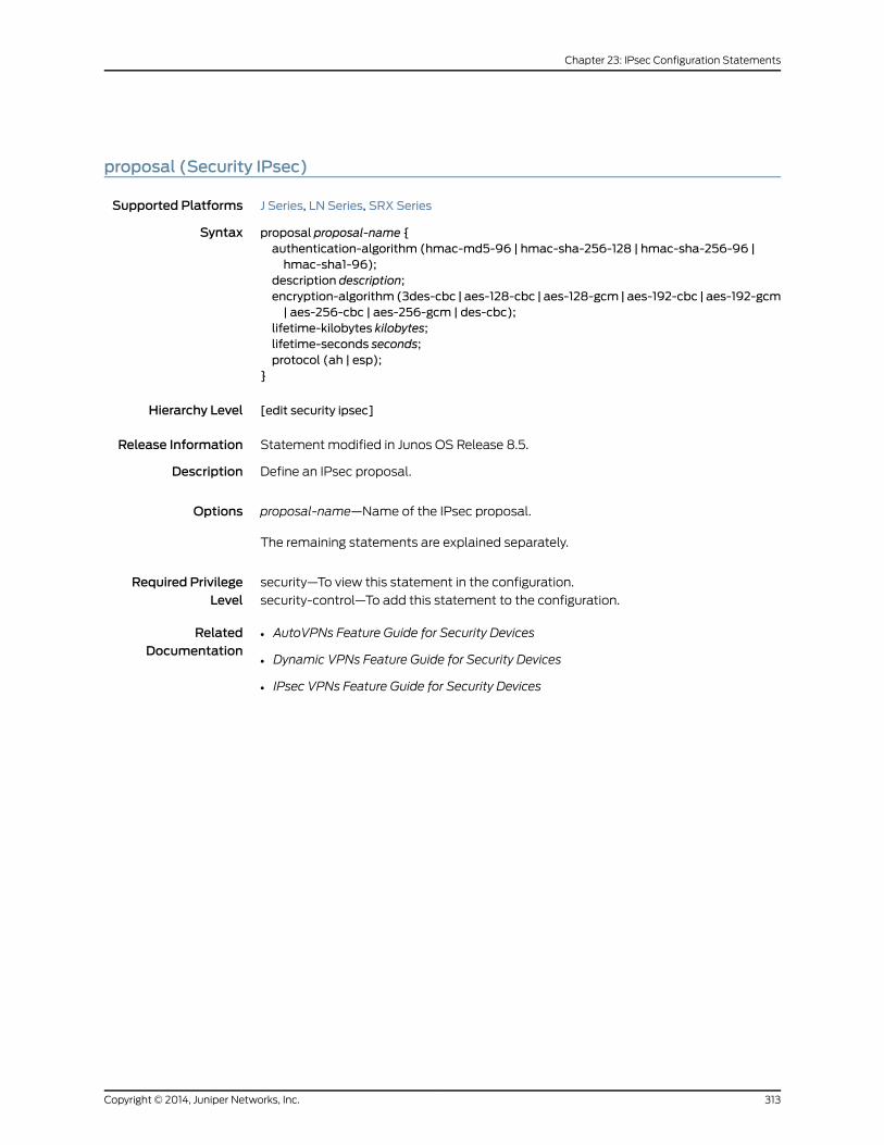
proposal (Security IPsec)
Supported Platforms J Series, LN Series, SRX Series
Syntax proposal proposal-name {authentication-algorithm (hmac-md5-96 | hmac-sha-256-128 | hmac-sha-256-96 |hmac-sha1-96);
description description;encryption-algorithm (3des-cbc | aes-128-cbc | aes-128-gcm | aes-192-cbc | aes-192-gcm| aes-256-cbc | aes-256-gcm | des-cbc);
lifetime-kilobytes kilobytes;lifetime-seconds seconds;protocol (ah | esp);
}
Hierarchy Level [edit security ipsec]
Release Information Statement modified in Junos OS Release 8.5.
Description Define an IPsec proposal.
Options proposal-name—Name of the IPsec proposal.
The remaining statements are explained separately.
Required PrivilegeLevel
security—To view this statement in the configuration.
security-control—To add this statement to the configuration.
RelatedDocumentation
• AutoVPNs Feature Guide for Security Devices
• Dynamic VPNs Feature Guide for Security Devices
• IPsec VPNs Feature Guide for Security Devices
313Copyright © 2014, Juniper Networks, Inc.
Chapter 23: IPsec Configuration Statements

proposal-set (Security IPsec)
Supported Platforms J Series, LN Series, SRX Series
Syntax proposal-set (basic | compatible | standard | suiteb-gcm-128 | suiteb-gcm-256);
Hierarchy Level [edit security ipsec policy policy-name]
Release Information Statement introduced in Junos OS Release 10.4. Support for suiteb-gcm-128 and
suiteb-gcm-256 options added in Junos OS Release 12.1X45-D10.
Description Define a set of default IPsec proposals.
Options basic —nopfs-esp-des-sha and nopfs-esp-des-md5•
• compatible—nopfs-esp-3des-sha, nopfs-esp-3des-md5, nopfs-esp-des-sha, and
nopfs-esp-des-md5
• standard—g2-esp-3des-sha and g2-esp-aes128-sha
• suiteb-gcm-128—Provides the following Suite B proposal:
• Encapsulating Security Payload (ESP) protocol
• Encryption algorithm—Advanced Encryption Standard Galois/Counter mode
(AES-GCM)128-bit
• Authentication algorithm—None (AES-GCM provides both encryption and
authentication)
NOTE: This option is not supported on group VPNs.
• suiteb-gcm-256—Provides the following Suite B proposal:
• ESP protocol
• Encryption algorithm—AES-GCM 256-bit
• Authentication algorithm—None (AES-GCM provides both encryption and
authentication)
NOTE: This option is not supported on group VPNs.
NOTE: Perfect Forward Secrecy setting in IPsec policy will override thesettings in proposal-sets in Release 10.4 and later.
Copyright © 2014, Juniper Networks, Inc.314
IPsec VPNs Feature Guide for Security Devices
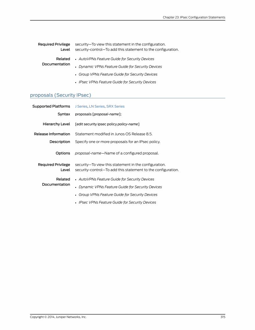
Required PrivilegeLevel
security—To view this statement in the configuration.
security-control—To add this statement to the configuration.
RelatedDocumentation
• AutoVPNs Feature Guide for Security Devices
• Dynamic VPNs Feature Guide for Security Devices
• Group VPNs Feature Guide for Security Devices
• IPsec VPNs Feature Guide for Security Devices
proposals (Security IPsec)
Supported Platforms J Series, LN Series, SRX Series
Syntax proposals [proposal-name];
Hierarchy Level [edit security ipsec policy policy-name]
Release Information Statement modified in Junos OS Release 8.5.
Description Specify one or more proposals for an IPsec policy.
Options proposal-name—Name of a configured proposal.
Required PrivilegeLevel
security—To view this statement in the configuration.
security-control—To add this statement to the configuration.
RelatedDocumentation
• AutoVPNs Feature Guide for Security Devices
• Dynamic VPNs Feature Guide for Security Devices
• Group VPNs Feature Guide for Security Devices
• IPsec VPNs Feature Guide for Security Devices
315Copyright © 2014, Juniper Networks, Inc.
Chapter 23: IPsec Configuration Statements
protocol (Security IPsec)
Supported Platforms J Series, LN Series, SRX Series
Syntax protocol (ah | esp);
Hierarchy Level [edit security ipsec proposal proposal-name ]
Release Information Statement modified in Junos OS Release 8.5.
Description Define the IPsec protocol for a manual or dynamic security association (SA).
NOTE: The device deletes existing IPsec SAs when you update theencryption-algorithm configuration in the IPsec proposal.
Options • ah—Authentication Header protocol.
• esp—Encapsulating Security Payload (ESP) protocol.
Required PrivilegeLevel
security—To view this statement in the configuration.
security-control—To add this statement to the configuration.
RelatedDocumentation
• AutoVPNs Feature Guide for Security Devices
• Dynamic VPNs Feature Guide for Security Devices
• IPsec VPNs Feature Guide for Security Devices
Copyright © 2014, Juniper Networks, Inc.316
IPsec VPNs Feature Guide for Security Devices

protocol (Security IPsecManual SA)
Supported Platforms J Series, LN Series, SRX Series
Syntax protocol (ah | esp)
Hierarchy Level [edit security ipsec vpn vpn-namemanual]
Release Information Statement modified in Junos OS Release 8.5.
Description Define the IPsec protocol for the manual security association. (This statement is not
supported on dynamic VPN implementations.)
Options • ah—Authentication Header protocol.
• esp—ESP protocol (To use the ESP protocol, you must also use the tunnel statement
at the [edit security ipsec security-association sa-name mode] hierarchy level.)
Required PrivilegeLevel
security—To view this statement in the configuration.
security-control—To add this statement to the configuration.
RelatedDocumentation
• Group VPNs Feature Guide for Security Devices
• IPsec VPNs Feature Guide for Security Devices
317Copyright © 2014, Juniper Networks, Inc.
Chapter 23: IPsec Configuration Statements

proxy-identity
Supported Platforms J Series, LN Series, SRX Series
Syntax proxy-identity {local ip-prefix;remote ip-prefix;service (all | service-name);
}
Hierarchy Level [edit security ipsec vpn vpn-name ike]
Release Information Statement introduced in Junos OS Release 8.5.
Description Optionally specify the IPsec proxy ID to use in negotiations. The default behavior is to
use the identities taken from the firewall policies.
Options The remaining statements are explained separately.
Required PrivilegeLevel
security—To view this statement in the configuration.
security-control—To add this statement to the configuration.
RelatedDocumentation
• AutoVPNs Feature Guide for Security Devices
• Dynamic VPNs Feature Guide for Security Devices
• Group VPNs Feature Guide for Security Devices
• IPsec VPNs Feature Guide for Security Devices
Copyright © 2014, Juniper Networks, Inc.318
IPsec VPNs Feature Guide for Security Devices
remote (Security IPsec)
Supported Platforms J Series, LN Series, SRX Series
Syntax remote ip-prefix;
Hierarchy Level [edit security ipsec vpn vpn-name ike proxy-identity]
Release Information Statement introduced in Junos OS Release 8.5. Support for IPv6 addresses added in
Junos OS Release 11.1.
Description Specify the remote IPv4 or IPv6 address and subnet mask for the proxy identity.
Options ip-prefix —IPv4 or IPv6 address and subnet mask.
Required PrivilegeLevel
security—To view this statement in the configuration.
security-control—To add this statement to the configuration.
RelatedDocumentation
• AutoVPNs Feature Guide for Security Devices
• Dynamic VPNs Feature Guide for Security Devices
• Group VPNs Feature Guide for Security Devices
• IPsec VPNs Feature Guide for Security Devices
service (Security IPsec)
Supported Platforms J Series, LN Series, SRX Series
Syntax service (all | service-name);
Hierarchy Level [edit security ipsec vpn vpn-name ike proxy-identity]
Release Information Statement introduced in Junos OS Release 8.5.
Description Specify the service (port and protocol combination) to protect.
Options service-name —Name of the service, as defined with system-services (Interface
Host-Inbound Traffic) and system-services (Zone Host-Inbound Traffic).
Required PrivilegeLevel
security—To view this statement in the configuration.
security-control—To add this statement to the configuration.
RelatedDocumentation
• AutoVPNs Feature Guide for Security Devices
• Dynamic VPNs Feature Guide for Security Devices
• Group VPNs Feature Guide for Security Devices
• IPsec VPNs Feature Guide for Security Devices
319Copyright © 2014, Juniper Networks, Inc.
Chapter 23: IPsec Configuration Statements

session-affinity
Supported Platforms LN Series, SRX1400, SRX3400, SRX3600, SRX5600, SRX5800
Syntax session-affinity ipsec
Hierarchy Level [edit security flow load-distribution]
Release Information Statement introduced in Junos OS Release 11.4R5.
Description Enable VPN session affinity.
Required PrivilegeLevel
security—To view this statement in the configuration.
security-control—To add this statement to the configuration.
RelatedDocumentation
• IPsec VPNs Feature Guide for Security Devices
source-interface (Security)
Supported Platforms J Series, LN Series, SRX Series
Syntax source-interface interface-name ;
Hierarchy Level [edit security ipsec vpn vpn-name vpn-monitor]
Release Information Statement introduced in Junos OS Release 8.5.
Description Specify the source interface for ICMP requests (VPN monitoring “hellos” ). If no source
interface is specified, the device automatically uses the local tunnel endpoint interface.
(This statement is not supported on dynamic VPN implementations.)
Options interface-name —Name of the interface for the ICMP requests.
Required PrivilegeLevel
security—To view this statement in the configuration.
security-control—To add this statement to the configuration.
RelatedDocumentation
• AutoVPNs Feature Guide for Security Devices
• Group VPNs Feature Guide for Security Devices
• IPsec VPNs Feature Guide for Security Devices
Copyright © 2014, Juniper Networks, Inc.320
IPsec VPNs Feature Guide for Security Devices
spi (Security IPsec)
Supported Platforms J Series, LN Series, SRX Series
Syntax spi spi-value;
Hierarchy Level [edit security ipsec vpn vpn-namemanual]
Release Information Statement modified in Junos OS Release 8.5.
Description Configure a security parameter index (SPI) for a security association (SA). (This statement
is not supported on dynamic VPN implementations.)
Options spi-value —An arbitrary value that uniquely identifies which security association (SA) to
use at the receiving host (the destination address in the packet).
Range: 256 through 16639
Required PrivilegeLevel
security—To view this statement in the configuration.
security-control—To add this statement to the configuration.
RelatedDocumentation
• Group VPNs Feature Guide for Security Devices
• IPsec VPNs Feature Guide for Security Devices
321Copyright © 2014, Juniper Networks, Inc.
Chapter 23: IPsec Configuration Statements
traceoptions (Security IPsec)
Supported Platforms J Series, LN Series, SRX Series
Syntax traceoptions {flag flag;
}
Hierarchy Level [edit security ipsec]
Release Information Statement introduced in Junos OS Release 8.5.
Description Configure IPsec tracing options.
Options • flag—To specify more than one trace operation, include multiple flag statements.
• all—Trace with all flags enabled
• next-hop-tunnel-binding—Trace next-hop tunnel binding events
• packet-drops—Trace packet drop activity
• packet-processing—Trace data packet processing events
• security-associations—Trace security association (SA) management events
Required PrivilegeLevel
trace—To view this statement in the configuration.
trace-control—To add this statement to the configuration.
RelatedDocumentation
• AutoVPNs Feature Guide for Security Devices
• Dynamic VPNs Feature Guide for Security Devices
• Group VPNs Feature Guide for Security Devices
• IPsec VPNs Feature Guide for Security Devices
Copyright © 2014, Juniper Networks, Inc.322
IPsec VPNs Feature Guide for Security Devices

trusted-ca (Security IKE Policy)
Supported Platforms LN Series
Syntax trusted-ca (ca-index | use-all);
Hierarchy Level [edit security group-vpnmember ike policy policy-name certificate][edit security group-vpn server ike policy policy-name certificate][edit security ike policy policy-name certificate]
Release Information Statement introduced in Junos OS Release 8.5. Support for group-vpn hierarchies added
in Junos OS Release 10.2.
Description Specify the preferred certificate authority (CA) to use when requesting a certificate from
the peer. If no value is specified, then no certificate request is sent (although incoming
certificates are still accepted). (This statement is not supported on dynamic VPN
implementations.)
Options • ca-index—Preferred certificate authority ID for the device to use.
• use-all—Device uses all configured certificate authorities.
Required PrivilegeLevel
security—To view this statement in the configuration.
security-control—To add this statement to the configuration.
RelatedDocumentation
• Group VPNs Feature Guide for Security Devices
• IPsec VPNs Feature Guide for Security Devices
323Copyright © 2014, Juniper Networks, Inc.
Chapter 23: IPsec Configuration Statements
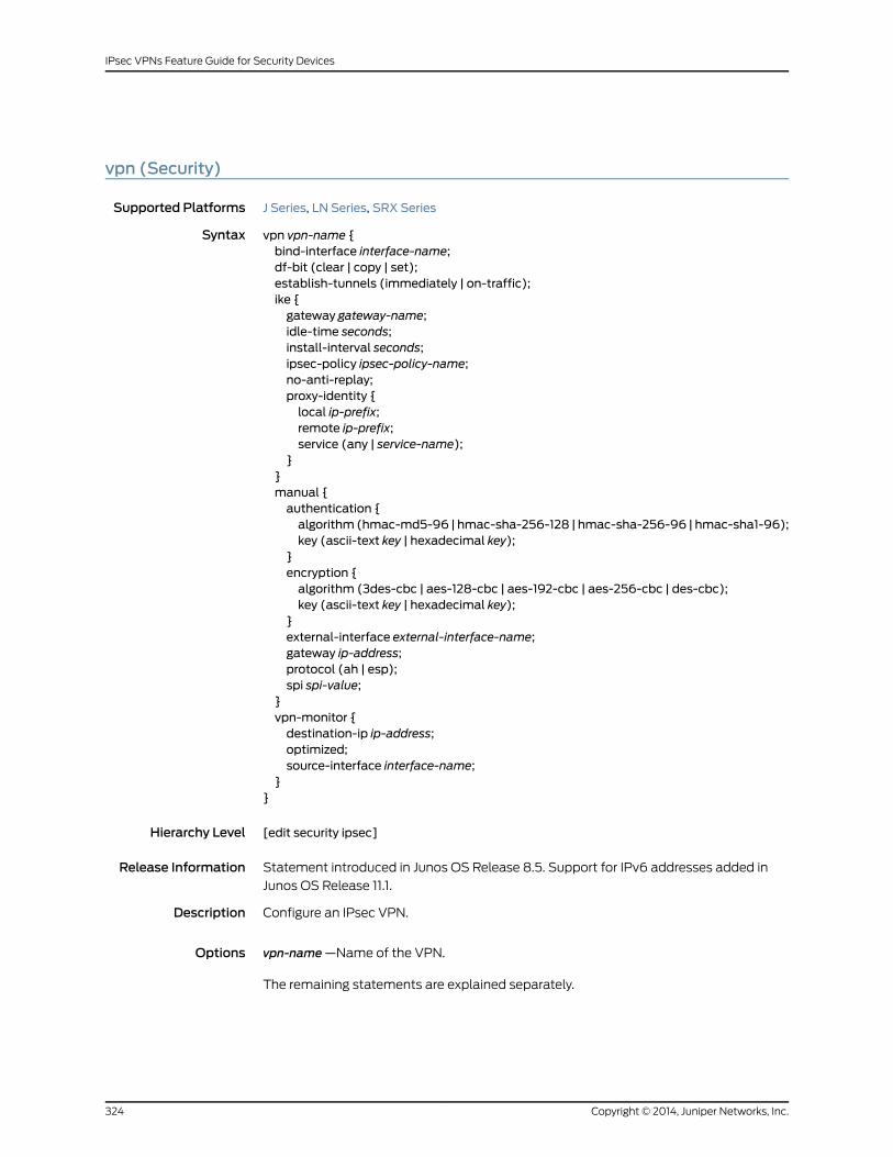
vpn (Security)
Supported Platforms J Series, LN Series, SRX Series
Syntax vpn vpn-name {bind-interface interface-name;df-bit (clear | copy | set);establish-tunnels (immediately | on-traffic);ike {gateway gateway-name;idle-time seconds;install-interval seconds;ipsec-policy ipsec-policy-name;no-anti-replay;proxy-identity {local ip-prefix;remote ip-prefix;service (any | service-name);
}}manual {authentication {algorithm (hmac-md5-96 | hmac-sha-256-128 | hmac-sha-256-96 | hmac-sha1-96);key (ascii-text key | hexadecimal key);
}encryption {algorithm (3des-cbc | aes-128-cbc | aes-192-cbc | aes-256-cbc | des-cbc);key (ascii-text key | hexadecimal key);
}external-interface external-interface-name;gateway ip-address;protocol (ah | esp);spi spi-value;
}vpn-monitor {destination-ip ip-address;optimized;source-interface interface-name;
}}
Hierarchy Level [edit security ipsec]
Release Information Statement introduced in Junos OS Release 8.5. Support for IPv6 addresses added in
Junos OS Release 11.1.
Description Configure an IPsec VPN.
Options vpn-name —Name of the VPN.
The remaining statements are explained separately.
Copyright © 2014, Juniper Networks, Inc.324
IPsec VPNs Feature Guide for Security Devices
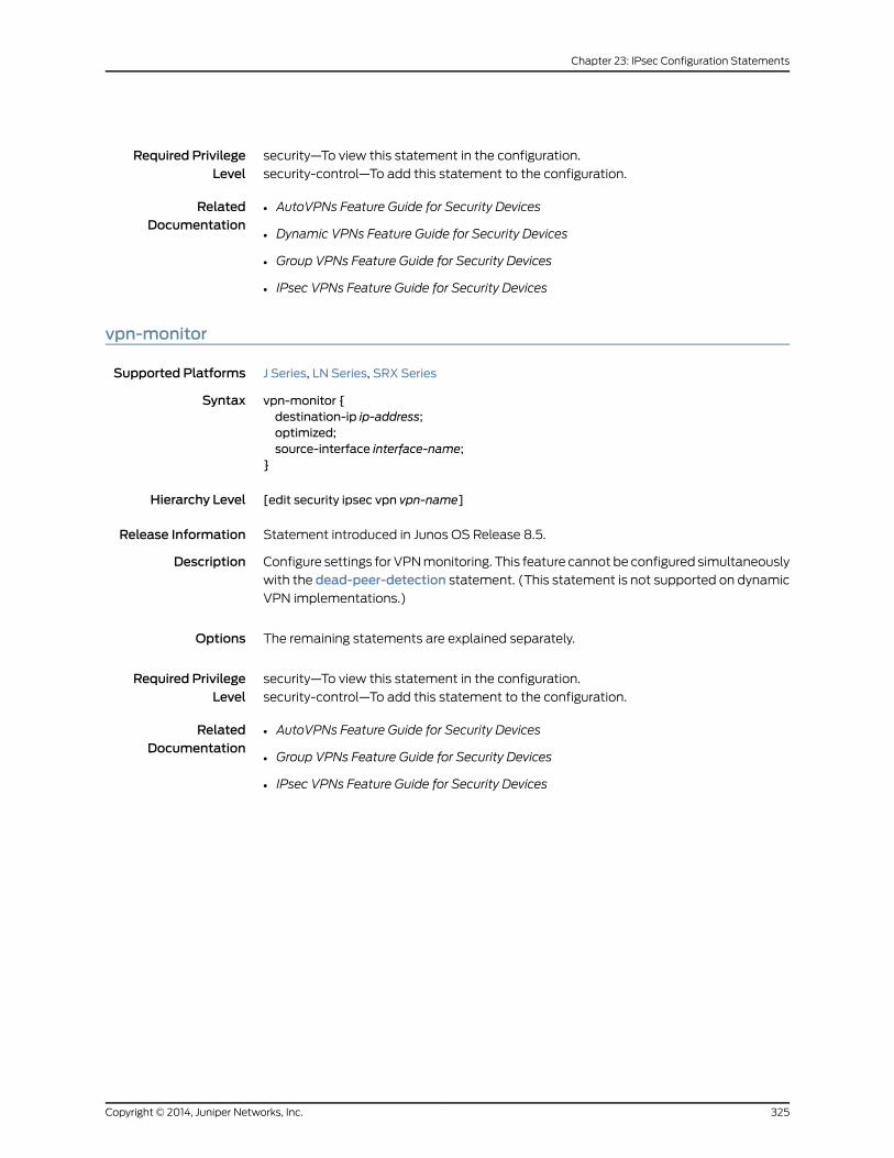
Required PrivilegeLevel
security—To view this statement in the configuration.
security-control—To add this statement to the configuration.
RelatedDocumentation
• AutoVPNs Feature Guide for Security Devices
• Dynamic VPNs Feature Guide for Security Devices
• Group VPNs Feature Guide for Security Devices
• IPsec VPNs Feature Guide for Security Devices
vpn-monitor
Supported Platforms J Series, LN Series, SRX Series
Syntax vpn-monitor {destination-ip ip-address;optimized;source-interface interface-name;
}
Hierarchy Level [edit security ipsec vpn vpn-name]
Release Information Statement introduced in Junos OS Release 8.5.
Description Configure settings for VPN monitoring. This feature cannot be configured simultaneously
with the dead-peer-detection statement. (This statement is not supported on dynamic
VPN implementations.)
Options The remaining statements are explained separately.
Required PrivilegeLevel
security—To view this statement in the configuration.
security-control—To add this statement to the configuration.
RelatedDocumentation
• AutoVPNs Feature Guide for Security Devices
• Group VPNs Feature Guide for Security Devices
• IPsec VPNs Feature Guide for Security Devices
325Copyright © 2014, Juniper Networks, Inc.
Chapter 23: IPsec Configuration Statements

vpn-monitor-options
Supported Platforms J Series, LN Series, SRX Series
Syntax vpn-monitor-options {interval seconds;threshold number;
}
Hierarchy Level [edit security ipsec]
Release Information Statement introduced in Junos OS Release 8.5.
Description Configure VPN monitoring options. (This statement is not supported on dynamic VPN
implementations.)
Options • interval seconds —Interval at which to send ICMP requests to the peer.
Range: 2 through 3600 seconds
Default: 10 seconds
• threshold number —Number of consecutive unsuccessful pings before the peer is
declared unreachable.
Range: 1 through 65536 pings
Default: 10 pings
Required PrivilegeLevel
security—To view this statement in the configuration.
security-control—To add this statement to the configuration.
RelatedDocumentation
• AutoVPNs Feature Guide for Security Devices
• Group VPNs Feature Guide for Security Devices
• IPsec VPNs Feature Guide for Security Devices
Copyright © 2014, Juniper Networks, Inc.326
IPsec VPNs Feature Guide for Security Devices
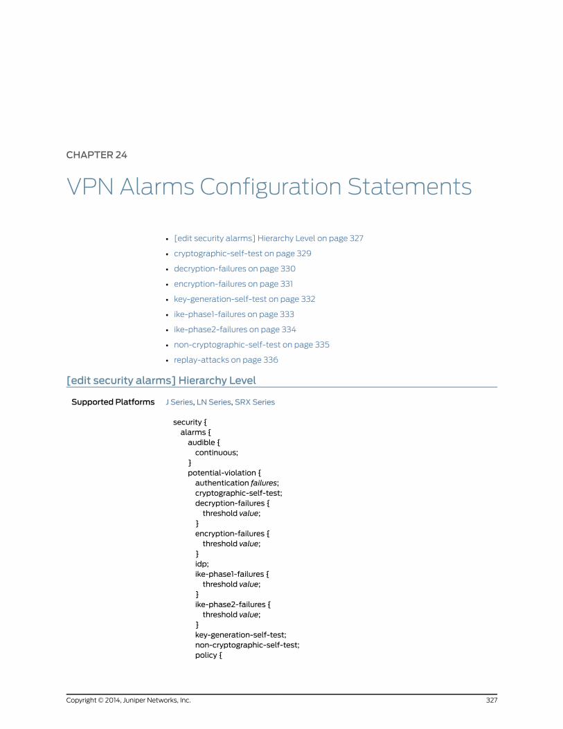
CHAPTER 24
VPN Alarms Configuration Statements
• [edit security alarms] Hierarchy Level on page 327
• cryptographic-self-test on page 329
• decryption-failures on page 330
• encryption-failures on page 331
• key-generation-self-test on page 332
• ike-phase1-failures on page 333
• ike-phase2-failures on page 334
• non-cryptographic-self-test on page 335
• replay-attacks on page 336
[edit security alarms] Hierarchy Level
Supported Platforms J Series, LN Series, SRX Series
security {alarms {audible {continuous;
}potential-violation {authentication failures;cryptographic-self-test;decryption-failures {threshold value;
}encryption-failures {threshold value;
}idp;ike-phase1-failures {threshold value;
}ike-phase2-failures {threshold value;
}key-generation-self-test;non-cryptographic-self-test;policy {
327Copyright © 2014, Juniper Networks, Inc.

application {duration interval;size count;threshold value;
}destination-ip {duration interval;size count;threshold value;
}policy match {duration interval;size count;threshold value;
}source-ip {duration interval;size count;threshold value;
}}replay-attacks {threshold value;
}security-log-percent-full percentage;
}}
}
RelatedDocumentation
IPsec VPNs Feature Guide for Security Devices•
• IDP Policies Feature Guide for Security Devices
Copyright © 2014, Juniper Networks, Inc.328
IPsec VPNs Feature Guide for Security Devices

cryptographic-self-test
Supported Platforms LN Series, SRX Series
Syntax cryptographic-self-test;
Hierarchy Level [edit security alarms potential-violation ]
Release Information Statement introduced in Junos OS Release 11.2.
Description Raise a security alarm when the device or switch detects a cryptographic self-test failure.
Cryptographic self-tests are a set of preoperational tests that are performed after the
device or switch is powered on. The self-test run without operator intervention.
Default No alarm is raised upon failure of a cryptographic self-test.
Required PrivilegeLevel
security—To view this statement in the configuration.
security-control—To add this statement to the configuration.
RelatedDocumentation
• Dynamic VPNs Feature Guide for Security Devices
• Group VPNs Feature Guide for Security Devices
• IPsec VPNs Feature Guide for Security Devices
329Copyright © 2014, Juniper Networks, Inc.
Chapter 24: VPN Alarms Configuration Statements

decryption-failures
Supported Platforms LN Series, SRX100, SRX110, SRX210, SRX220, SRX240, SRX550, SRX650
Syntax decryption-failures {threshold value;
}
Hierarchy Level [edit security alarms potential-violation]
Release Information Statement introduced in Junos OS Release 11.2.
Description Raise a security alarm after exceeding a specified number of decryption failures.
Default Multiple decryption failures do not cause an alarm to be raised.
Options failures—Number of decryption failures up to which an alarm is not raised. When the
configured number is exceeded, an alarm is raised.
Range: 0 through 1 through 1,000,000,000.
Default: 1000
Required PrivilegeLevel
security—To view this statement in the configuration.
security-control—To add this statement to the configuration.
RelatedDocumentation
• Dynamic VPNs Feature Guide for Security Devices
• Group VPNs Feature Guide for Security Devices
• IPsec VPNs Feature Guide for Security Devices
Copyright © 2014, Juniper Networks, Inc.330
IPsec VPNs Feature Guide for Security Devices
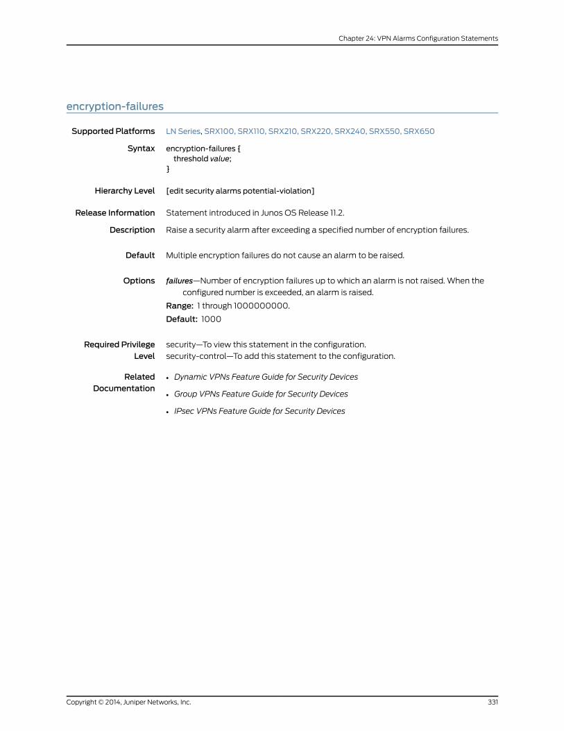
encryption-failures
Supported Platforms LN Series, SRX100, SRX110, SRX210, SRX220, SRX240, SRX550, SRX650
Syntax encryption-failures {threshold value;
}
Hierarchy Level [edit security alarms potential-violation]
Release Information Statement introduced in Junos OS Release 11.2.
Description Raise a security alarm after exceeding a specified number of encryption failures.
Default Multiple encryption failures do not cause an alarm to be raised.
Options failures—Number of encryption failures up to which an alarm is not raised. When the
configured number is exceeded, an alarm is raised.
Range: 1 through 1000000000.
Default: 1000
Required PrivilegeLevel
security—To view this statement in the configuration.
security-control—To add this statement to the configuration.
RelatedDocumentation
• Dynamic VPNs Feature Guide for Security Devices
• Group VPNs Feature Guide for Security Devices
• IPsec VPNs Feature Guide for Security Devices
331Copyright © 2014, Juniper Networks, Inc.
Chapter 24: VPN Alarms Configuration Statements
key-generation-self-test
Supported Platforms LN Series, SRX Series
Syntax key-generation-self-test;
Hierarchy Level [edit security alarms potential-violation]
Release Information Statement introduced in Junos OS Release 11.2.
Description Raise a security alarm when the device or switch detects a key generation self-test failure.
Key generation is the process of generating keys for cryptography. A key is used to encrypt
and decrypt data. The self-tests run without operator intervention.
Default No alarm is raised upon failure of a key generation self-test.
Required PrivilegeLevel
security—To view this statement in the configuration.
security-control—To add this statement to the configuration.
RelatedDocumentation
• Dynamic VPNs Feature Guide for Security Devices
• Group VPNs Feature Guide for Security Devices
• IPsec VPNs Feature Guide for Security Devices
Copyright © 2014, Juniper Networks, Inc.332
IPsec VPNs Feature Guide for Security Devices

ike-phase1-failures
Supported Platforms LN Series, SRX100, SRX110, SRX210, SRX220, SRX240, SRX550, SRX650
Syntax ike-phase1-failures {threshold value;
}
Hierarchy Level [edit security alarms potential-violation]
Release Information Statement introduced in Junos OS Release 11.2.
Description Raise a security alarm after exceeding a specified number of Internet Key Exchange (IKE)
Phase 1 failures.
Default Multiple IKE phase 1 failures do not cause an alarm to be raised.
Options failures—Number of IKE phase 1 failures up to which an alarm is not raised. When the
configured number is exceeded, an alarm is raised.
Range: 1 through 1000000000.
Default: 20
Required PrivilegeLevel
security—To view this statement in the configuration.
security-control—To add this statement to the configuration.
RelatedDocumentation
• Dynamic VPNs Feature Guide for Security Devices
• Group VPNs Feature Guide for Security Devices
• IPsec VPNs Feature Guide for Security Devices
333Copyright © 2014, Juniper Networks, Inc.
Chapter 24: VPN Alarms Configuration Statements
ike-phase2-failures
Supported Platforms LN Series, SRX100, SRX110, SRX210, SRX220, SRX240, SRX550, SRX650
Syntax ike-phase2-failures {threshold value;
}
Hierarchy Level [edit security alarms potential-violation]
Release Information Statement introduced in Junos OS Release 11.2.
Description Raise a security alarm after exceeding a specified number of Internet Key Exchange (IKE)
phase 2 failures.
Default Multiple IKE phase 2 failures do not cause an alarm to be raised.
Options failures—Number of IKE phase 2 failures up to which an alarm is not raised. When the
configured number is exceeded, an alarm is raised.
Range: 1 through 1000000000.
Default: 20
Required PrivilegeLevel
security—To view this statement in the configuration.
security-control—To add this statement to the configuration.
RelatedDocumentation
• Dynamic VPNs Feature Guide for Security Devices
• Group VPNs Feature Guide for Security Devices
• IPsec VPNs Feature Guide for Security Devices
Copyright © 2014, Juniper Networks, Inc.334
IPsec VPNs Feature Guide for Security Devices

non-cryptographic-self-test
Supported Platforms LN Series, SRX Series
Syntax non-cryptographic-self-test;
Hierarchy Level [edit security alarms potential-violation]
Release Information Statement introduced in Junos OS Release 11.2.
Description Raise a security alarm when the device or switch detects a noncryptographic self-test
failure. The self-tests run without operator intervention.
Default No alarm is raised upon failure of a noncryptographic self-test.
Required PrivilegeLevel
security—To view this statement in the configuration.
security-control—To add this statement to the configuration.
RelatedDocumentation
• Dynamic VPNs Feature Guide for Security Devices
• Group VPNs Feature Guide for Security Devices
• IPsec VPNs Feature Guide for Security Devices
335Copyright © 2014, Juniper Networks, Inc.
Chapter 24: VPN Alarms Configuration Statements
replay-attacks
Supported Platforms LN Series, SRX Series
Syntax replay-attacks {threshold value;
}
Hierarchy Level [edit security alarms potential-violation]
Release Information Statement introduced in Junos OS Release 11.2.
Description Raise a security alarm when the device detects a replay attack. A replay attack is a form
of network attack in which a valid data transmission is maliciously or fraudulently repeated
or delayed.
Default Replay attacks do not raise security alarms.
Options • threshold value—Number of reply attacks up to which an alarm is not raised. When the
configured number is exceeded, an alarm is raised.
Range: Range: 0 through 100,00,00,000.
Required PrivilegeLevel
security—To view this statement in the configuration.
security-control—To add this statement to the configuration.
RelatedDocumentation
• Dynamic VPNs Feature Guide for Security Devices
• Group VPNs Feature Guide for Security Devices
• IPsec VPNs Feature Guide for Security Devices
Copyright © 2014, Juniper Networks, Inc.336
IPsec VPNs Feature Guide for Security Devices

PART 3
Administration
• Operational Commands on page 339
337Copyright © 2014, Juniper Networks, Inc.

Copyright © 2014, Juniper Networks, Inc.338
IPsec VPNs Feature Guide for Security Devices
CHAPTER 25
Operational Commands
• clear security ike respond-bad-spi-count
• clear security ike security-associations
• clear security ipsec security-associations
• clear security ipsec statistics
• request security ike debug-disable
• request security ike debug-enable
• show security ike active-peer
• show security ike debug-status
• show security ike pre-shared-key
• show security ike security-associations
• show security ike tunnel-map
• show security ipsec inactive-tunnels
• show security ipsec next-hop-tunnels
• show security ipsec security-associations
• show security ipsec statistics
339Copyright © 2014, Juniper Networks, Inc.
clear security ike respond-bad-spi-count
Supported Platforms J Series, LN Series, SRX Series
Syntax clear security ike respond-bad-spi-count< gateway-name >
Release Information Command introduced in Junos OS Release 8.5.
Description Clear information about invalid Internet Key Exchange (IKE) security parameter index
(SPI) counters.
Options none—Clear all invalid SPI counters.•
• gateway-name —(Optional) Clear the invalid SPI counters for the given gateway.
Required PrivilegeLevel
clear
RelatedDocumentation
respond-bad-spi on page 278•
List of Sample Output clear security ike respond-bad-spi-count on page 340clear security ike respond-bad-spi-count gateway-name1 on page 340
Output Fields This command produces no output.
Sample Output
clear security ike respond-bad-spi-count
user@host> clear security ike respond-bad-spi-count
Sample Output
clear security ike respond-bad-spi-count gateway-name1
user@host> clear security ike respond-bad-spi-count gateway-name1
Copyright © 2014, Juniper Networks, Inc.340
IPsec VPNs Feature Guide for Security Devices

clear security ike security-associations
Supported Platforms J Series, LN Series, SRX Series
Syntax clear security ike security-associations< peer-address >< port ><fpc slot-number><index SA-index-number><kmd-instance (all | kmd-instance-name)><pic slot-number>port<family (inet | inet6)>
Release Information Command introduced in Junos OS Release 8.5. The fpc, pic, and kmd-instance options
added in Junos OS Release 9.3. The port option added in Junos OS Release 10.0. The
family option added in Junos OS Release 11.1.
Description Clear information about the current Internet Key Exchange security associations (IKE
SAs). For IKEv2, the device clears the information about the IKE SAs and the associated
IPSec SA.
Options • none—Clear all IKE SAs.
• peer-address —(Optional) Clear IKE SAs for the destination peer at this IP address.
• fpc slot-number —Specific to SRX Series devices. Clear information about existing IKE
SAs in this Flexible PIC Concentrator (FPC) slot.
• index SA-index-number —(Optional) Clear the IKE SA with this index number.
• port—(Optional) Port number of SA (1 through 65,535).
• kmd-instance—Specific to SRX Series devices. Clear information about existing IKE
SAs in the key management process (the daemon, which in this case is KMD) identified
by FPC slot-number and PIC slot-number.
• all—All KMD instances running on the Services Processing Unit (SPU).
• kmd-instance-name—Name of the KMD instance running on the SPU.
• pic slot-number —Specific to SRX Series devices. Clear information about existing IKE
SAs in this PIC slot.
• family—(Optional) Clear IKE SAs by family.
• inet—IPv4 address family.
• inet6—IPv6 address family.
Required PrivilegeLevel
clear
341Copyright © 2014, Juniper Networks, Inc.
Chapter 25: Operational Commands

RelatedDocumentation
show security ike security-associations on page 352•
List of Sample Output clear security ike security-associations on page 342clear security ike security-associations 1.1.1.2 port 19405 on page 342clear security ike security-associations index 8 on page 342clear security ike security-associations family inet6 on page 342clear security ike security-associations fpc 5 pic 0 kmd-instance all (SRX SeriesDevices) on page 342
Output Fields This command produces no output.
Sample Output
clear security ike security-associations
user@host> clear security ike security-associations
Sample Output
clear security ike security-associations 1.1.1.2 port 19405
user@host> clear security ike security-associations 1.1.1.2 port 19405
Sample Output
clear security ike security-associations index 8
user@host> clear security ike security-associations index 8
Sample Output
clear security ike security-associations family inet6
user@host> clear security ike security-associations family inet6
Sample Output
clear security ike security-associations fpc 5 pic 0 kmd-instance all (SRX Series Devices)
user@host> clear security ike security-associations fpc 5 pic 0 kmd-instance all
Copyright © 2014, Juniper Networks, Inc.342
IPsec VPNs Feature Guide for Security Devices

clear security ipsec security-associations
Supported Platforms J Series, LN Series, SRX Series
Syntax clear security ipsec security-associationsfpc slot-number<index SA-index-number>kmd-instance (all | kmd-instance-name )pic slot-number<family (inet | inet6)>
Release Information Command introduced in Junos OS Release 8.5. The fpc, pic, and kmd-instance options
added in Junos OS Release 9.3. The family option added in Junos OS Release 11.1.
Description Clear information about IPsec security associations (SAs).
Options • none—Clear all IPsec SAs.
• fpc slot-number —Specific to SRX Series devices. Clear information about existing
IPsec SAs in this Flexible PIC Concentrator (FPC) slot.
• index SA-index-number —(Optional) Clear the IPsec SA with this index number.
• kmd-instance—Specific to SRX Series devices. Clear information about existing IPsec
SAs in the key management process (the daemon, which in this case is KMD) identified
by FPC slot-number and PIC slot-number .
• all—All KMD instances running on the Services Processing Unit (SPU).
• kmd-instance-name—Name of the KMD instance running on the SPU.
pic slot-number —Specific to SRX Series devices. Clear information about existing IPsec
SAs in this PIC slot.
family—(Optional) Clear SAs by family.
• inet—IPv4 address family.
• inet6—IPv6 address family.
Required PrivilegeLevel
clear
RelatedDocumentation
show security ipsec security-associations on page 364•
List of Sample Output clear security ipsec security-associations on page 344clear security ipsec security-associations index 8 on page 344clear security ipsec security-associations family inet6 on page 344
Output Fields This command produces no output.
343Copyright © 2014, Juniper Networks, Inc.
Chapter 25: Operational Commands
Sample Output
clear security ipsec security-associations
user@host> clear security ipsec security-associations
Sample Output
clear security ipsec security-associations index 8
user@host> clear security ipsec security-associations index 8
Sample Output
clear security ipsec security-associations family inet6
user@host> clear security ipsec security-associations family inet6
Copyright © 2014, Juniper Networks, Inc.344
IPsec VPNs Feature Guide for Security Devices

clear security ipsec statistics
Supported Platforms J Series, LN Series, SRX Series
Syntax clear security ike statistics<fpc slot-number><index SA-index-number><kmd-instance (all | kmd-instance-name )><pic slot-number>
Release Information Command introduced in Junos OS Release 8.5. fpc and pic options added in Junos OS
Release 9.3. kmd-instance option added in Junos OS Release 10.4.
Description Clear IPsec statistics on the device.
Options • none—Clear all IPsec statistics.
• fpc slot-number —Specific to SRX Series devices. Clear statistics about existing IPsec
security associations (SAs) in this Flexible PIC Concentrator (FPC) slot.
• index SA-index-number—(Optional) Clear the IPsec statistics for the SA with this index
number.
• kmd-instance—Specific to SRX Series devices. Clear information about existing IKE
SAs in the key management process (the daemon, which in this case is KMD) identified
by FPC slot-number and PIC slot-number .
• all—All KMD instances running on the Services Processing Unit (SPU).
• kmd-instance-name—Name of the KMD instance running on the SPU.
• pic slot-number —Specific to SRX Series devices. Clear statistics about existing IPsec
SAs in this PIC slot.
Required PrivilegeLevel
clear
RelatedDocumentation
show security ipsec statistics on page 371•
List of Sample Output clear security ipsec statistics on page 345clear security ipsec statistics index 1 on page 346clear security ipsec statistics fpc 5 pic 0 (SRX Series devices) on page 346
Output Fields This command produces no output.
Sample Output
clear security ipsec statistics
user@host> clear security ipsec statistics
345Copyright © 2014, Juniper Networks, Inc.
Chapter 25: Operational Commands

Sample Output
clear security ipsec statistics index 1
user@host> clear security ipsec statistics index 1
Sample Output
clear security ipsec statistics fpc 5 pic 0 (SRX Series devices)
user@host> clear security ipsec statistics fpc 5 pic 0
Copyright © 2014, Juniper Networks, Inc.346
IPsec VPNs Feature Guide for Security Devices

request security ike debug-disable
Supported Platforms LN Series, SRX100, SRX1400, SRX210, SRX220, SRX240, SRX3400, SRX3600, SRX550,
SRX5600, SRX5800, SRX650
Syntax request security ike debug-disable
Release Information Command introduced in Release Junos OS 11.4R3.
Description Disable IKE debugging.
Required PrivilegeLevel
maintenance
RelatedDocumentation
request security ike debug-enable on page 348•
• show security ike debug-status on page 350
List of Sample Output request security ike debug-disable on page 347
Output Fields This command produces no output.
Sample Output
request security ike debug-disable
user@host> request security ike debug-disable
347Copyright © 2014, Juniper Networks, Inc.
Chapter 25: Operational Commands
request security ike debug-enable
Supported Platforms LN Series, SRX100, SRX1400, SRX210, SRX220, SRX240, SRX3400, SRX3600, SRX550,
SRX5600, SRX5800, SRX650
Syntax request security ike debug-enable local local-ip-address remote remote-ip-address
Release Information Command introduced in Junos OS Release 11.4R3.
Description Enable IKE debugging.
Options local local-ip-address—The address of the local peer.•
• remote remote-ip-address—The address of the remote peer.
Required PrivilegeLevel
maintenance
RelatedDocumentation
request security ike debug-disable on page 347•
• show security ike debug-status on page 350
List of Sample Output request security ike debug-enable local 1.1.1.1 remote 2.2.2.2 on page 348
Output Fields This command produces no output.
Sample Output
request security ike debug-enable local 1.1.1.1 remote 2.2.2.2
user@host> request security ike debug-enable local 1.1.1.1 remote 2.2.2.2
Copyright © 2014, Juniper Networks, Inc.348
IPsec VPNs Feature Guide for Security Devices

show security ike active-peer
Supported Platforms J Series, LN Series, SRX Series
Syntax show security ike active-peer
Release Information Command introduced in Junos OS Release 10.4.
Description This command is used to display the list of connected active users with details about
the peer addresses and ports they are using.
Required PrivilegeLevel
view
RelatedDocumentation
show security ike security-associations on page 352•
• show security ipsec security-associations on page 364
• Junos OS VPN Library for Security Devices
List of Sample Output show security ike active-peer on page 349
Sample Output
show security ike active-peer
user@host> show security ike active-peer
Remote Address Port Peer IKE-ID XAUTH username Assigned IP172.27.6.136 8034 tleungjtac@650a tleung 10.123.80.225
349Copyright © 2014, Juniper Networks, Inc.
Chapter 25: Operational Commands

show security ike debug-status
Supported Platforms LN Series, SRX100, SRX1400, SRX210, SRX220, SRX240, SRX3400, SRX3600, SRX550,
SRX5600, SRX5800, SRX650
Syntax show security ike debug-status
Release Information Command introduced in Junos OS Release 11.4R3.
Description Display debug information for currently enabled Internet Key Exchange (IKE).
Required PrivilegeLevel
view
RelatedDocumentation
request security ike debug-disable on page 347•
• request security ike debug-enable on page 348
List of Sample Output show security ike debug-status on page 350
Sample Output
show security ike debug-status
user@host> show security ike debug-statusEnabledflag: alllevel: 15
Copyright © 2014, Juniper Networks, Inc.350
IPsec VPNs Feature Guide for Security Devices
show security ike pre-shared-key
Supported Platforms J Series, LN Series, SRX Series
Syntax show security ike pre-shared key<master-key master-key ><user-id user-id >
Release Information Command introduced in Junos OS Release 8.5.
Description Display the Internet Key Exchange (IKE) preshared key used by the Virtual Private network
(VPN) gateway to authenticate the remote access user.
Options master-key master-key —(Optional) Master preshared key.•
• user-id user-id —(Optional) IKE user ID value.
Required PrivilegeLevel
view
RelatedDocumentation
pre-shared-key (Security IKE Policy) on page 273•
List of Sample Output show security ike pre-shared-key on page 351
Sample Output
show security ike pre-shared-key
user@host> show security ike pre-shared-key user-id [email protected] juniperPreshared Key:3b33ec3631a561ec5a710f5d02f208033b108bb4
351Copyright © 2014, Juniper Networks, Inc.
Chapter 25: Operational Commands

show security ike security-associations
Supported Platforms J Series, LN Series, SRX Series
Syntax show security ike security-associationspeer-addressbrief | detailfpc slot-numberindex SA-index-numberkmd-instance (all | kmd-instance-name)pic slot-numberfamily (inet | inet6)
Release Information Command introduced in Junos OS Release 8.5 . The fpc, pic, and kmd-instance options
added in Junos OS Release 9.3. The family option added in Junos OS Release 11.1.
Description Display information about Internet Key Exchange security associations (IKE SAs).
Options • none—Display standard information about existing IKE SAs, including index numbers.
• peer-address—(Optional) Display details about a particular SA based on the IPv4 or
IPv6 address of the destination peer. This option and index provide the same level of
output.
• brief—(Optional) Display standard information about all existing IKE SAs. (Default)
• detail—(Optional) Display detailed information about all existing IKE SAs.
• fpc slot-number—(Optional) Specific to SRX Series devices. Display information about
existing IKE SAs in this Flexible PIC Concentrator (FPC) slot. This option is used to filter
the output.
• index SA-index-number—(Optional) Display information for a particular SA based on
the index number of the SA. For a particular SA, display the list of existing SAs by using
the command with no options. This option and peer-address provide the same level of
output.
• kmd-instance—(Optional) Specific to SRX Series devices. Display information about
existing IKE SAs in the key management process (in this case, it is KMD) identified by
FPC slot-number and PIC slot-number. This option is used to filter the output.
• all—All KMD instances running on the Services Processing Unit (SPU).
• kmd-instance-name—Name of the KMD instance running on the SPU.
• pic slot-number—(Optional) Specific to SRX Series devices. Display information about
existing IKE SAs in this PIC slot. This option is used to filter the output.
• family—(Optional) Display IKE SAs by family. This option is used to filter the output.
• inet—IPv4 address family.
• inet6—IPv6 address family.
Copyright © 2014, Juniper Networks, Inc.352
IPsec VPNs Feature Guide for Security Devices

Required PrivilegeLevel
view
RelatedDocumentation
clear security ike security-associations on page 341•
• Junos OS VPN Library for Security Devices
• Master Administrator for Logical Systems Feature Guide for Security Devices
List of Sample Output show security ike security-associations (IPv4) on page 355show security ike security-associations (IPv6) on page 355showsecurity ikesecurity-associationsdetail (BranchSRXSeriesDevices)onpage356show security ike security-associations detail (For High-End SRX SeriesDevices) on page 356show security ike security-associations family inet6 on page 357show security ike security-associations index 8 detail on page 357show security ike security-associations 1.1.1.2 on page 358show security ike security-associations fpc 6 pic 1 kmd-instance all (SRX SeriesDevices) on page 358
Output Fields Table 49 on page 353 lists the output fields for the showsecurity ike security-associations
command. Output fields are listed in the approximate order in which they appear.
Table 49: show security ike security-associations Output Fields
Field DescriptionField Name
IP address of the destination peer with which the local peer communicates.IKE Peer or Remote Address
Index number of an SA. This number is an internally generated number you can use todisplay information about a single SA.
Index
Name of the IKE gateway.Gateway Name
• FPC—Flexible PIC Concentrator (FPC) slot number.
• PIC—PIC slot number.
• KMD-Instance—The name of the KMD instance running on the SPU, identified by FPCslot-number and PIC slot-number. Currently, 4 KMD instances are running on eachSPU, and any particular IKE negotiation is carried out by a single KMD instance.
Location
Part played in the IKE session. The device triggering the IKE negotiation is the initiator,and the device accepting the first IKE exchange packets is the responder.
Role
State of the IKE SAs:
• DOWN—SA has not been negotiated with the peer.
• UP—SA has been negotiated with the peer.
State
Random number, called a cookie, which is sent to the remote node when the IKEnegotiation is triggered.
Initiator cookie
353Copyright © 2014, Juniper Networks, Inc.
Chapter 25: Operational Commands
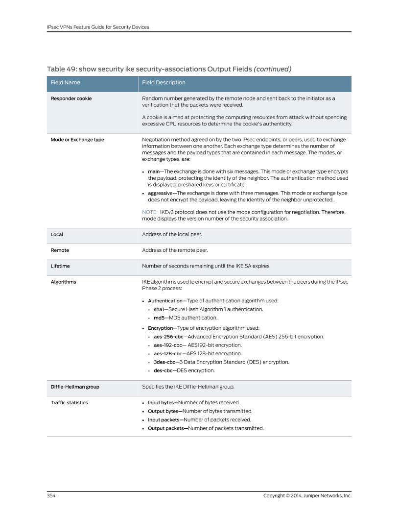
Table 49: show security ike security-associations Output Fields (continued)
Field DescriptionField Name
Random number generated by the remote node and sent back to the initiator as averification that the packets were received.
A cookie is aimed at protecting the computing resources from attack without spendingexcessive CPU resources to determine the cookie's authenticity.
Responder cookie
Negotiation method agreed on by the two IPsec endpoints, or peers, used to exchangeinformation between one another. Each exchange type determines the number ofmessages and the payload types that are contained in each message. The modes, orexchange types, are:
• main—The exchange is done with six messages. This mode or exchange type encryptsthe payload, protecting the identity of the neighbor. The authentication method usedis displayed: preshared keys or certificate.
• aggressive—The exchange is done with three messages. This mode or exchange typedoes not encrypt the payload, leaving the identity of the neighbor unprotected.
NOTE: IKEv2 protocol does not use the mode configuration for negotiation. Therefore,mode displays the version number of the security association.
Mode or Exchange type
Address of the local peer.Local
Address of the remote peer.Remote
Number of seconds remaining until the IKE SA expires.Lifetime
IKE algorithms used to encrypt and secure exchanges between the peers during the IPsecPhase 2 process:
• Authentication—Type of authentication algorithm used:
• sha1—Secure Hash Algorithm 1 authentication.
• md5—MD5 authentication.
• Encryption—Type of encryption algorithm used:
• aes-256-cbc—Advanced Encryption Standard (AES) 256-bit encryption.
• aes-192-cbc— AES192-bit encryption.
• aes-128-cbc—AES 128-bit encryption.
• 3des-cbc—3 Data Encryption Standard (DES) encryption.
• des-cbc—DES encryption.
Algorithms
Specifies the IKE Diffie-Hellman group.Diffie-Hellman group
• Input bytes—Number of bytes received.
• Output bytes—Number of bytes transmitted.
• Input packets—Number of packets received.
• Output packets—Number of packets transmitted.
Traffic statistics
Copyright © 2014, Juniper Networks, Inc.354
IPsec VPNs Feature Guide for Security Devices

Table 49: show security ike security-associations Output Fields (continued)
Field DescriptionField Name
Notification to the key management process of the status of the IKE negotiation:
• caller notification sent—Caller program notified about the completion of the IKEnegotiation.
• waiting for done—Negotiation is done. The library is waiting for the remote endretransmission timers to expire.
• waiting for remove—Negotiation has failed. The library is waiting for the remote endretransmission timers to expire before removing this negotiation.
• waiting for policymanager—Negotiation is waiting for a response from the policymanager.
Flags
• number created: The number of SAs created.
• number deleted: The number of SAs deleted.
IPSec security associations
Number of Phase 2 IKE negotiations in progress and status information:
• Negotiation type—Type of Phase 2 negotiation. Junos OS currently supports quickmode.
• Message ID—Unique identifier for a Phase 2 negotiation.
• Local identity—Identity of the local Phase 2 negotiation. The format is id-type-name(proto-name:port-number,[0..id-data-len] = iddata-presentation).
• Remote identity—Identity of the remote Phase 2 negotiation. The format is id-type-name(proto-name:port-number,[0..id-data-len] = iddata-presentation).
• Flags—Notification to the key management process of the status of the IKE negotiation:
• caller notification sent—Caller program notified about the completion of the IKEnegotiation.
• waiting for done—Negotiation is done. The library is waiting for the remote endretransmission timers to expire.
• waiting for remove—Negotiation has failed. The library is waiting for the remote endretransmission timers to expire before removing this negotiation.
• waiting for policymanager—Negotiation is waiting for a response from the policymanager.
Phase 2 negotiations in progress
Sample Output
show security ike security-associations (IPv4)
user@host> show security ike security-associationsIndex Remote Address State Initiator cookie Responder cookie Mode8 1.1.1.2 UP 3a895f8a9f620198 9040753e66d700bb MainIndex Remote Address State Initiator cookie Responder cookie Mode9 1.2.1.3 UP 5ba96hfa9f65067 1 70890755b65b80b d Main
Sample Output
show security ike security-associations (IPv6)
user@host> show security ike security-associationsIndex State Initiator cookie Responder cookie Mode Remote Address
5 UP e48efd6a444853cf 0d09c59aafb720be Aggressive 1212::1112
355Copyright © 2014, Juniper Networks, Inc.
Chapter 25: Operational Commands
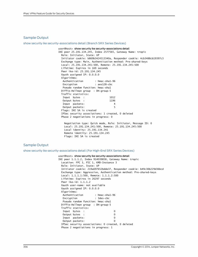
Sample Output
show security ike security-associations detail (Branch SRX Series Devices)
user@host> show security ike security-associations detailIKE peer 25.191.134.245, Index 2577565, Gateway Name: tropic Role: Initiator, State: UP Initiator cookie: b869b3424513340a, Responder cookie: 4cb3488cb19397c3 Exchange type: Main, Authentication method: Pre-shared-keys Local: 25.191.134.241:500, Remote: 25.191.134.245:500 Lifetime: Expires in 169 seconds Peer ike-id: 25.191.134.245 Xauth assigned IP: 0.0.0.0 Algorithms: Authentication : hmac-sha1-96 Encryption : aes128-cbc Pseudo random function: hmac-sha1 Diffie-Hellman group : DH-group-5 Traffic statistics: Input bytes : 1012 Output bytes : 1196 Input packets: 4 Output packets: 5 Flags: IKE SA is created IPSec security associations: 1 created, 0 deleted Phase 2 negotiations in progress: 0
Negotiation type: Quick mode, Role: Initiator, Message ID: 0 Local: 25.191.134.241:500, Remote: 25.191.134.245:500 Local identity: 25.191.134.241 Remote identity: 25.191.134.245 Flags: IKE SA is created
Sample Output
show security ike security-associations detail (For High-End SRX Series Devices)
user@host> show security ike security-associations detailIKE peer 1.1.1.2, Index 914039858, Gateway Name: tropic Location: FPC 3, PIC 1, KMD-Instance 3 Role: Initiator, State: UP Initiator cookie: 219a697652bdde37, Responder cookie: b49c30b229d36bcd Exchange type: Aggressive, Authentication method: Pre-shared-keys Local: 1.1.1.1:500, Remote: 1.1.1.2:500 Lifetime: Expires in 26297 seconds Peer ike-id: 1.1.1.2 Xauth user-name: not available Xauth assigned IP: 0.0.0.0 Algorithms: Authentication : hmac-sha1-96 Encryption : 3des-cbc Pseudo random function: hmac-sha1 Diffie-Hellman group : DH-group-5 Traffic statistics: Input bytes : 0 Output bytes : 0 Input packets: 0 Output packets: 0 IPSec security associations: 0 created, 0 deleted Phase 2 negotiations in progress: 1
Copyright © 2014, Juniper Networks, Inc.356
IPsec VPNs Feature Guide for Security Devices
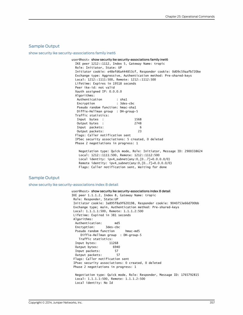
Sample Output
show security ike security-associations family inet6
user@host> show security ike security-associations family inet6 IKE peer 1212::1112, Index 5, Gateway Name: tropic Role: Initiator, State: UP Initiator cookie: e48efd6a444853cf, Responder cookie: 0d09c59aafb720be Exchange type: Aggressive, Authentication method: Pre-shared-keys Local: 1212::1111:500, Remote: 1212::1112:500 Lifetime: Expires in 19518 seconds Peer ike-id: not valid Xauth assigned IP: 0.0.0.0 Algorithms: Authentication : sha1 Encryption : 3des-cbc Pseudo random function: hmac-sha1 Diffie-Hellman group : DH-group-5 Traffic statistics: Input bytes : 1568 Output bytes : 2748 Input packets: 6 Output packets: 23 Flags: Caller notification sent IPSec security associations: 5 created, 0 deleted Phase 2 negotiations in progress: 1
Negotiation type: Quick mode, Role: Initiator, Message ID: 2900338624 Local: 1212::1111:500, Remote: 1212::1112:500 Local identity: ipv4_subnet(any:0,[0..7]=0.0.0.0/0) Remote identity: ipv4_subnet(any:0,[0..7]=0.0.0.0/0) Flags: Caller notification sent, Waiting for done
Sample Output
show security ike security-associations index 8 detail
user@host> show security ike security-associations index 8 detailIKE peer 1.1.1.2, Index 8, Gateway Name: tropic Role: Responder, State:UP Initiator cookie: 3a895f8a9f620198, Responder cookie: 9040753e66d700bb Exchange type; main, Authentication method: Pre-shared-keys Local: 1.1.1.1:500, Remote: 1.1.1.2:500 Lifetime: Expired in 381 seconds Algorithms: Authentication: md5 Encryption: 3des-cbc Pseudo random function hmac-md5 Diffie-Hellman group : DH-group-5 Traffic statistics: Input bytes: 11268 Output bytes: 6940 Input packets: 57 Output packets: 57 Flags: Caller notification sent IPsec security associations: 0 created, 0 deleted Phase 2 negotiations in progress: 1
Negotiation type: Quick mode, Role: Responder, Message ID: 1765792815 Local: 1.1.1.1:500, Remote: 1.1.1.2:500 Local identity: No Id
357Copyright © 2014, Juniper Networks, Inc.
Chapter 25: Operational Commands

Remote identity: No Id Flags: Caller notification sent, Waiting for remove
Sample Output
show security ike security-associations 1.1.1.2
user@host> show security ike security-associations 1.1.1.2Index State Initiator cookie Responder cookie Mode Remote Address 8 UP 3a895f8a9f620198 9040753e66d700bb Main 1.1.1.2
Sample Output
show security ike security-associations fpc 6 pic 1 kmd-instance all (SRX Series Devices)
user@host> show security ike security-associations fpc 6 pic 1 kmd-instance allIndex Remote Address State Initiator cookie Responder cookie Mode
1728053250 1.1.1.2 UP fc959afd1070d10b bdeb7e8c1ea99483 Main
Copyright © 2014, Juniper Networks, Inc.358
IPsec VPNs Feature Guide for Security Devices
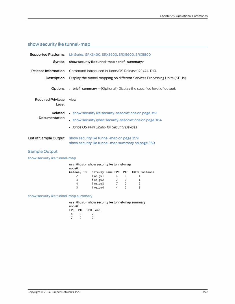
show security ike tunnel-map
Supported Platforms LN Series, SRX3400, SRX3600, SRX5600, SRX5800
Syntax show security ike tunnel-map <brief | summary>
Release Information Command introduced in Junos OS Release 12.1x44-D10.
Description Display the tunnel mapping on different Services Processing Units (SPUs).
Options • brief | summary —(Optional) Display the specified level of output.
Required PrivilegeLevel
view
RelatedDocumentation
show security ike security-associations on page 352•
• show security ipsec security-associations on page 364
• Junos OS VPN Library for Security Devices
List of Sample Output show security ike tunnel-map on page 359show security ike tunnel-map summary on page 359
Sample Output
show security ike tunnel-map
user@host> show security ike tunnel-mapnode0:Gateway ID Gateway Name FPC PIC IKED Instance 2 ike_gw1 4 0 1 3 ike_gw2 7 0 1 4 ike_gw3 7 0 2 5 ike_gw4 4 0 2
show security ike tunnel-map summary
user@host> show security ike tunnel-map summarynode0:FPC PIC SPU Load 4 0 2 7 0 2
359Copyright © 2014, Juniper Networks, Inc.
Chapter 25: Operational Commands
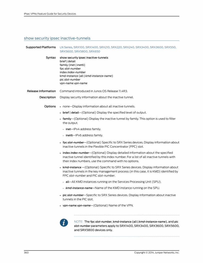
show security ipsec inactive-tunnels
Supported Platforms LN Series, SRX100, SRX1400, SRX210, SRX220, SRX240, SRX3400, SRX3600, SRX550,
SRX5600, SRX5800, SRX650
Syntax show security ipsec inactive-tunnelsbrief | detailfamily (inet | inet6)fpc slot-numberindex index-numberkmd-instance (all | kmd-instance-name)pic slot-numbervpn-name vpn-name
Release Information Command introduced in Junos OS Release 11.4R3.
Description Display security information about the inactive tunnel.
Options • none—Display information about all inactive tunnels.
• brief | detail—(Optional) Display the specified level of output.
• family—(Optional) Display the inactive tunnel by family. This option is used to filter
the output.
• inet—IPv4 address family.
• inet6—IPv6 address family.
• fpc slot-number—(Optional) Specific to SRX Series devices. Display information about
inactive tunnels in the Flexible PIC Concentrator (FPC) slot.
• index index-number—(Optional) Display detailed information about the specified
inactive tunnel identified by this index number. For a list of all inactive tunnels with
their index numbers, use the command with no options.
• kmd-instance—(Optional) Specific to SRX Series devices. Display information about
inactive tunnels in the key management process (in this case, it is KMD) identified by
FPC slot-number and PIC slot-number.
• all—All KMD instances running on the Services Processing Unit (SPU).
• kmd-instance-name—Name of the KMD instance running on the SPU.
• pic slot-number—Specific to SRX Series devices. Display information about inactive
tunnels in the PIC slot.
• vpn-name vpn-name—(Optional) Name of the VPN.
NOTE: The fpc slot-number, kmd-instance (all | kmd-instance-name), and pic
slot-number parameters apply to SRX1400, SRX3400, SRX3600, SRX5600,
and SRX5800 devices only.
Copyright © 2014, Juniper Networks, Inc.360
IPsec VPNs Feature Guide for Security Devices
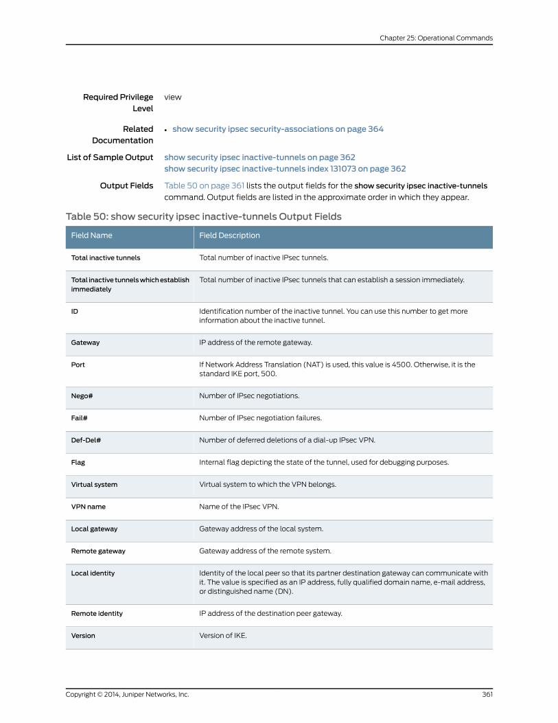
Required PrivilegeLevel
view
RelatedDocumentation
show security ipsec security-associations on page 364•
List of Sample Output show security ipsec inactive-tunnels on page 362show security ipsec inactive-tunnels index 131073 on page 362
Output Fields Table 50 on page 361 lists the output fields for the show security ipsec inactive-tunnels
command. Output fields are listed in the approximate order in which they appear.
Table 50: show security ipsec inactive-tunnels Output Fields
Field DescriptionField Name
Total number of inactive IPsec tunnels.Total inactive tunnels
Total number of inactive IPsec tunnels that can establish a session immediately.Total inactive tunnelswhichestablishimmediately
Identification number of the inactive tunnel. You can use this number to get moreinformation about the inactive tunnel.
ID
IP address of the remote gateway.Gateway
If Network Address Translation (NAT) is used, this value is 4500. Otherwise, it is thestandard IKE port, 500.
Port
Number of IPsec negotiations.Nego#
Number of IPsec negotiation failures.Fail#
Number of deferred deletions of a dial-up IPsec VPN.Def-Del#
Internal flag depicting the state of the tunnel, used for debugging purposes.Flag
Virtual system to which the VPN belongs.Virtual system
Name of the IPsec VPN.VPN name
Gateway address of the local system.Local gateway
Gateway address of the remote system.Remote gateway
Identity of the local peer so that its partner destination gateway can communicate withit. The value is specified as an IP address, fully qualified domain name, e-mail address,or distinguished name (DN).
Local identity
IP address of the destination peer gateway.Remote identity
Version of IKE.Version
361Copyright © 2014, Juniper Networks, Inc.
Chapter 25: Operational Commands

Table 50: show security ipsec inactive-tunnels Output Fields (continued)
Field DescriptionField Name
State of the don't fragment bit: set or clear.DF-bit
The tunnel interface to which the route-based VPN is bound.Bind-interface
Name of the applicable policy.Policy-name
Reason for which the tunnel is inactive.Tunnel Down Reason
Sample Output
show security ipsec inactive-tunnels
user@host> show security ipsec inactive-tunnelsTotal inactive tunnels: 5 Total inactive tunnels with establish immediately: 1 ID Port Nego# Fail# Flag Gateway Tunnel Down Reason 2 500 0 0 604829 SA not initiated 3 500 0 0 600829 12.2.3.110 SA not initiated 131073 500 419 0 600a29 12.2.2.110 P1 SA deleted 131074 500 0 0 600a29 12.2.2.110 SA not initiated 131075 500 0 0 600a29 12.2.4.110 SA not initiated
Sample Output
show security ipsec inactive-tunnels index 131073
user@host> show security ipsec inactive-tunnels index 131073ID: 131073 Virtual-system: root, VPN Name: tropic Local Gateway: 12.2.2.109, Remote Gateway: 12.2.2.110 Local Identity: ipv4_subnet(any:0,[0..7]=0.0.0.0/0) Remote Identity: ipv4_subnet(any:0,[0..7]=30.1.1.0/24) Version: IKEv1 DF-bit: clear Bind-interface: st0.3
Port: 500, Nego#: 0, Fail#: 0, Def-Del#: 0 Flag: 600a29 Tunnel Down Reason: SA not initiated
Copyright © 2014, Juniper Networks, Inc.362
IPsec VPNs Feature Guide for Security Devices

show security ipsec next-hop-tunnels
Supported Platforms J Series, LN Series, SRX Series
Syntax show security ipsec next-hop-tunnels< interface-name interface-name >
Release Information Command introduced in Junos OS Release 8.5.
Description Display security information about the secure tunnel interface.
Options none—Display information about all secure tunnel interface.•
• interface-name interface-name—(Optional) Name of the secure tunnel logical interface.
Required PrivilegeLevel
view
RelatedDocumentation
show security ipsec security-associations on page 364•
• Junos OS VPN Library for Security Devices
List of Sample Output show security ipsec next-hop-tunnels on page 363
Output Fields Table 51 on page 363 lists the output fields for the show security ipsec next-hop-tunnels
command. Output fields are listed in the approximate order in which they appear.
Table 51: show security ipsec next-hop-tunnels Output Fields
Field DescriptionField Name
IP address of the next gateway.Next-hop gateway
Name of the secure tunnel logical interface.Interface
Name of the IPsec VPN tunnel.IPsec VPN name
• Static—IP address manually configured.
• Auto—IP address obtained from the remote peer automatically.
Flag
Sample Output
show security ipsec next-hop-tunnels
user@host> show security ipsec next-hop-tunnelsNext-hop gateway interface IPsec VPN name Flag11.1.1.2 st0.0 autokey Static11.1.1.3 st0.0 pbd-4-6 Auto
363Copyright © 2014, Juniper Networks, Inc.
Chapter 25: Operational Commands

show security ipsec security-associations
Supported Platforms J Series, LN Series, SRX Series
Syntax show security ipsec security-associationsbrief | detailfpc slot-numberindex SA-index-numberkmd-instance (all | kmd-instance-name)pic slot-number>family (inet | inet6)vpn-name vpn-name
Release Information Command introduced in Junos OS Release 8.5. The fpc, pic, and kmd-instance options
added in Junos OS Release 9.3. The family option added in Junos OS Release 11.1. The
vpn-name option added in Junos OS Release 11.4R3.
Description Display information about the IPsec security associations (SAs).
Options • none—Display information about all SAs.
• brief | detail—(Optional) Display the specified level of output.
• fpc slot-number—(Optional) Specific to SRX Series devices. Display information about
existing IPsec SAs in this Flexible PIC Concentrator (FPC) slot. This option is used to
filter the output.
• index SA-index-number—(Optional) Display detailed information about the specified
SA identified by this index number. To obtain a list of all SAs that includes their index
numbers, use the command with no options.
• kmd-instance—(Optional) Specific to SRX Series devices. Display information about
existing IPsec SAs in the key management process (in this case, it is KMD) identified
by the FPC slot-number and PIC slot-number. This option is used to filter the output.
• all—All KMD instances running on the Services Processing Unit (SPU).
• kmd-instance-name—Name of the KMD instance running on the SPU.
• pic slot-number—(Optional) Specific to SRX Series devices. Display information about
existing IPsec SAs in this PIC slot. This option is used to filter the output.
• family—(Optional) Display SAs by family. This option is used to filter the output.
• inet—IPv4 address family.
• inet6—IPv6 address family.
• vpn-name vpn-name—Name of the VPN.
Required PrivilegeLevel
view
Copyright © 2014, Juniper Networks, Inc.364
IPsec VPNs Feature Guide for Security Devices

RelatedDocumentation
MPLS Feature Guide for Security Devices•
• clear security ipsec security-associations on page 343
• Junos OS VPN Library for Security Devices
• Master Administrator for Logical Systems Feature Guide for Security Devices
List of Sample Output show security ipsec security-associations (IPv4) on page 368show security ipsec security-associations (IPv6) on page 368show security ipsec security-associations index 5 on page 368show security ipsec security-associations brief on page 369show security ipsec security-associations detail on page 369show security ipsec security-associations detail (SRX Series Devices) on page 369show security ipsec security-associations family inet6 on page 370show security ipsec security-associations fpc 6 pic 1 kmd-instance all (SRX SeriesDevices) on page 370
Output Fields Table 52 on page 365 lists the output fields for the showsecurity ipsecsecurity-associations
command. Output fields are listed in the approximate order in which they appear.
Table 52: show security ipsec security-associations
Field DescriptionField Name
Total number of active IPsec tunnels.Total active tunnels
Index number of the SA. You can use this number to get additional information aboutthe SA.
ID
IPsec name for VPN.VPN name
IP address of the remote gateway.Gateway
If Network Address Translation (NAT) is used, this value is 4500. Otherwise, it is thestandard IKE port, 500.
Port
Cryptography used to secure exchanges between peers during the IKE Phase 2negotiations includes:
• An authentication algorithm used to authenticate exchanges between the peers.Options are hmac-md5-95, hmac-sha1-96, or ESP.
• An encryption algorithm used to encrypt data traffic. Options are3des-cbc, aes-128-cbc,aes-192-cbc, aes-256-cbc, or des-cbc.
Algorithm
Security parameter index (SPI) identifier. An SA is uniquely identified by an SPI. Eachentry includes the name of the VPN, the remote gateway address, the SPIs for eachdirection, the encryption and authentication algorithms, and keys. The peer gatewayseach have two SAs, one resulting from each of the two phases of negotiation: Phase 1and Phase 2.
SPI
The lifetime of the SA, after which it expires, expressed either in seconds or kilobytes.Life: sec/kb
365Copyright © 2014, Juniper Networks, Inc.
Chapter 25: Operational Commands

Table 52: show security ipsec security-associations (continued)
Field DescriptionField Name
State has two options, Installed and Not Installed.
• Installed—The SA is installed in the SA database.
• Not Installed—The SA is not installed in the SA database.
For transport mode, the value of State is always Installed.
Sta
The Mon field refers to VPN monitoring status. If VPN monitoring is enabled, then thisfield displays U (up) or D (down). A hyphen (-) means VPN monitoring is not enabledfor this SA.
Mon
The root system.vsys or Virtual-system
Numeric identifier of the specific IPsec tunnel for the SA.Tunnel index
Gateway address of the local system.Local gateway
Gateway address of the remote system.Remote gateway
Identity of the local peer so that its partner destination gateway can communicate withit. The value is specified as an IP address, fully qualified domain name, e-mail address,or distinguished name (DN).
Local identity
IP address of the destination peer gateway.Remote identity
State of the don't fragment bit: set or cleared.DF-bit
The tunnel interface to which VPN is bound.Bind interface
Name of the applicable policy.Policy-name
FPC—Flexible PIC Concentrator (FPC) slot number.
PIC—PIC slot number.
KMD-Instance—The name of the KMD instance running on the SPU, identified by FPCslot-number and PIC slot-number. Currently, 4 KMD instances running on each SPU, andany particular IPsec negotiation is carried out by a single KMD instance.
Location
Direction of the SA; it can be inbound or outbound.Direction
Value of the auxiliary security parameter index(SPI).
• When the value is AH or ESP, AUX-SPI is always 0.
• When the value is AH+ESP, AUX-SPI is always a positive integer.
AUX-SPI
Mode of the SA:
• transport—Protects host-to-host connections.
• tunnel—Protects connections between security gateways.
Mode
Copyright © 2014, Juniper Networks, Inc.366
IPsec VPNs Feature Guide for Security Devices

Table 52: show security ipsec security-associations (continued)
Field DescriptionField Name
Type of the SA:
• manual—Security parameters require no negotiation. They are static and are configuredby the user.
• dynamic—Security parameters are negotiated by the IKE protocol. Dynamic SAs arenot supported in transport mode.
Type
State of the SA:
• Installed—The SA is installed in the SA database.
• Not Installed—The SA is not installed in the SA database.
For transport mode, the value of State is always Installed.
State
Protocol supported.
• Transport mode supports Encapsulation Security Protocol (ESP) and AuthenticationHeader (AH).
• Tunnel mode supports ESP and AH.
• Authentication—Type of authentication used.
• Encryption—Type of encryption used.
Protocol
The soft lifetime informs the IPsec key management system that the SA is about toexpire.
Each lifetime of an SA has two display options, hard and soft, one of which must bepresent for a dynamic SA. This allows the key management system to negotiate a newSA before the hard lifetime expires.
• Expires in seconds—Number of seconds left until the SA expires.
Soft lifetime
The hard lifetime specifies the lifetime of the SA.
• Expires in seconds—Number of seconds left until the SA expires.
Hard lifetime
The lifesize remaining specifies the usage limits in kilobytes. If there is no lifesize specified,it shows unlimited.
• Expires in kilobytes—Number of kilobytes left until the SA expires.
Lifesize Remaining
State of the service that prevents packets from being replayed. It can be Enabled orDisabled.
Anti-replay service
Configured size of the antireplay service window. It can be 32 or 64 packets. If the replaywindow size is 0, the antireplay service is disabled.
The antireplay window size protects the receiver against replay attacks by rejecting oldor duplicate packets.
Replay window size
The tunnel interface to which the route-based VPN is bound.Bind-interface
367Copyright © 2014, Juniper Networks, Inc.
Chapter 25: Operational Commands

Sample Output
show security ipsec security-associations (IPv4)
user@host> show security ipsec security-associationsTotal active tunnels: 1ID Gateway Port Algorithm SPI Life:sec/kb Mon vsys 131075 11.0.28.241 500 ESP:3des/sha1 86758ff0 6918/ unlim - 0 131075 11.0.28.241 500 ESP:3des/sha1 3183ff26 6918/ unlim - 0
Sample Output
show security ipsec security-associations (IPv6)
user@host> show security ipsec security-associationsTotal active tunnels: 1ID Algorithm SPI Life:sec/kb Mon vsys Port Gateway 131074 ESP:3des/sha1 14caf1d9 3597/ unlim - root 500 1212::1112 131074 ESP:3des/sha1 9a4db486 3597/ unlim - root 500 1212::1112
Sample Output
show security ipsec security-associations index 5
user@host> show security ipsec security-associations index 5ID: 131073 Virtual-system: root, VPN Name: tropicLocal gateway: 1.1.1.1, Remote gateway: 1.1.1.2Local identity: ipv4_subnet(any:0,[0..7]=0.0.0.0/0)Remote identity: ipv4_subnet(any:0,[0...7]=0.0.0.0/0)Version: IKEv2DF-bit: clearBind-interface: st0.3Policy-name: my-policy
Direction: inbound, SPI: 494001027, AUX-SPI: 0Mode: tunnel, Type: dynamic, State: InstalledProtocol: ESP, Authentication: hmac-sha1-96, Encryption: 3des-cbcSoft lifetime: ExpiredHard lifetime: Expired in 130 secondsLifesize Remaining: UnlimitedAnti-replay service: Enabled, Replay window size: 64
Direction: inbound, SPI: 1498711950, AUX-SPI: 0Mode: tunnel, Type: dynamic, State: InstalledProtocol: ESP, Authentication: hmac-sha1-96, Encryption: 3des-cbcSoft lifetime: Expires in 40 secondsHard lifetime: Expires in 175 secondsLifesize Remaining: UnlimitedAnti-replay service: Enabled, Replay window size: 64
Direction: outbound, SPI: 4038397695, AUX-SPI: 0Mode: tunnel, Type: dynamic, State: InstalledProtocol: ESP, Authentication: hmac-sha1-96, Encryption: 3des-cbcSoft lifetime: Expires in 40 secondsHard lifetime: Expires in 175 secondsLifesize Remaining: UnlimitedAnti-replay service: Enabled, Replay window size: 64
Copyright © 2014, Juniper Networks, Inc.368
IPsec VPNs Feature Guide for Security Devices

Sample Output
show security ipsec security-associations brief
user@host> show security ipsec security-associations briefTotal active tunnels: 2ID Gateway Port Algorithm SPI Life:sec/kb Mon vsys<16384 1.1.1.1 500 ESP:3des/sha1 af88baa 28795/unlim D 0 >16384 1.1.1.1 500 ESP:3des/sha1 f4e3e5f4 28795/unlim D 0
Sample Output
show security ipsec security-associations detail
user@host> show security ipsec security-associations detailID: 131073 Virtual-system: root, VPN Name: tropicLocal Gateway: 1.1.1.2, Remote Gateway: 1.1.1.1Local Identity: ipv4_subnet(any:0,[0..7]=0.0.0.0/0)Remote Identity: ipv4_subnet(any:0,[0..7]=0.0.0.0/0)Version: IKEv2DF-bit: clearBind-interface: st0.3Direction: inbound, SPI: 184060842, AUX-SPI: 0Hard lifetime: Expires in 28785 secondsLifesize Remaining: UnlimitedSoft lifetime: ExpiredMode: tunnel, Type: dynamic, State: installed, VPN Monitoring: DOWNProtocol: ESP, Authentication: hmac-sha1-96, Encryption: 3des-cbcAnti-replay service: enabled, Replay window size: 32
Direction: outbound, SPI: 4108576244, AUX-SPI: 0Hard lifetime: Expires in 28785 secondsLifesize Remaining: UnlimitedSoft lifetime: ExpiredMode: tunnel, Type: dynamic, State: installed, VPN Monitoring: DOWNProtocol: ESP, Authentication: hmac-sha1-96, Encryption: 3des-cbcAnti-replay service: enabled, Replay window size: 32
Sample Output
show security ipsec security-associations detail (SRX Series Devices)
user@host> show security ipsec security-associations detailID: 131073 Virtual-system: root, VPN Name: tropic Local Gateway: 20.0.0.4, Remote Gateway: 30.0.0.2 Local Identity: ipv4_subnet(any:0,[0..7]=0.0.0.0/0) Remote Identity: ipv4(any:0,[0..3]=20.0.0.4) Version: IKEv2 DF-bit: clear Policy-name: p1 Bind-interface: st0.3 Location: FPC 1, PIC 2, KMD-Instance 3 Direction: inbound, SPI: 3727011331, AUX-SPI: 0 Hard lifetime: Expires in 3570 seconds Lifesize Remaining: Unlimited Soft lifetime: Expires in 3525 seconds Mode: tunnel, Type: dynamic, State: installed, VPN Monitoring: - Protocol: ESP, Authentication: hmac-sha1-96, Encryption: aes-cbc (128 bits) Anti-replay service: enabled, Replay window size: 32
Location: FPC 1, PIC 2, KMD-Instance 3
369Copyright © 2014, Juniper Networks, Inc.
Chapter 25: Operational Commands

Direction: outbound, SPI: 4212479378, AUX-SPI: 0 Hard lifetime: Expires in 3570 seconds Lifesize Remaining: Unlimited Soft lifetime: Expires in 3525 seconds Mode: tunnel, Type: dynamic, State: installed, VPN Monitoring: - Protocol: ESP, Authentication: hmac-sha1-96, Encryption: aes-cbc (128 bits) Anti-replay service: enabled, Replay window size: 32
Sample Output
show security ipsec security-associations family inet6
user@host> show security ipsec security-associations family inet6 Virtual-system: root Local Gateway: 1212::1111, Remote Gateway: 1212::1112 Local Identity: ipv4_subnet(any:0,[0..7]=0.0.0.0/0) Remote Identity: ipv4_subnet(any:0,[0..7]=0.0.0.0/0) DF-bit: clear Direction: inbound, SPI: 14caf1d9, AUX-SPI: 0 , VPN Monitoring: - Hard lifetime: Expires in 3440 seconds Lifesize Remaining: Unlimited Soft lifetime: Expires in 2813 seconds Mode: tunnel, Type: dynamic, State: installed Protocol: ESP, Authentication: hmac-sha1-96, Encryption: 3des-cbc Anti-replay service: counter-based enabled, Replay window size: 64
Direction: outbound, SPI: 9a4db486, AUX-SPI: 0 , VPN Monitoring: - Hard lifetime: Expires in 3440 seconds Lifesize Remaining: Unlimited Soft lifetime: Expires in 2813 seconds Mode: tunnel, Type: dynamic, State: installed Protocol: ESP, Authentication: hmac-sha1-96, Encryption: 3des-cbc Anti-replay service: counter-based enabled, Replay window size: 64
Sample Output
show security ipsec security-associations fpc 6 pic 1 kmd-instance all (SRX Series Devices)
user@host> show security ipsec security-associations fpc 6 pic 1 kmd-instance all Total active tunnels: 1
ID Gateway Port Algorithm SPI Life:sec/kb Mon vsys
<2 1.1.1.2 500 ESP:3des/sha1 67a7d25d 28280/unlim - 0
>2 1.1.1.2 500 ESP:3des/sha1 a23cbcdc 28280/unlim - 0
Copyright © 2014, Juniper Networks, Inc.370
IPsec VPNs Feature Guide for Security Devices

show security ipsec statistics
Supported Platforms J Series, LN Series, SRX Series
Syntax show security ipsec statistics<fpc slot-number ><index SA-index-number ><kmd-instance kmd-instance-name >pic slot-number
Release Information Command introduced in Junos OS Release 8.5. fpc and pic options added in Junos OS
Release 9.3. kmd-instance option added in Junos OS Release 10.4.
Description Display standard IPsec statistics.
Options none—Display statistics about all IPsec security associations (SAs).•
• fpc slot-number—Specific to SRX Series devices. Display statistics about existing IPsec
SAs in this Flexible PIC Concentrator (FPC) slot. This option is used to filter the output.
• index SA-index-number—(Optional) Display statistics for the SA with this index number.
• kmd-instance kmd-instance-name—Specific to SRX Series devices. Display information
about existing IKE SAs in the key management process (the daemon, which in this
case is KMD) identified by FPC slot-number and PIC slot-number. This option is used
to filter the output.
• all—All KMD instances running on the Services Processing Unit (SPU).
• kmd-instance-name—Name of the KMD instance running on the SPU.
• pic slot-number—Specific to SRX Series devices. Display statistics about existing IPsec
SAs in this PIC slot. This option is used to filter the output.
Required PrivilegeLevel
view
RelatedDocumentation
MPLS Feature Guide for Security Devices•
• clear security ipsec statistics on page 345
List of Sample Output show security ipsec statistics on page 372show security ipsec statistics index 5 on page 373show security ipsec statistics fpc 6 pic 1 (SRX Series devices) on page 373
Output Fields Table 53 on page 371 lists the output fields for the showsecurity ipsecstatisticscommand.
Output fields are listed in the approximate order in which they appear.
Table 53: show security ipsec statistics Output Fields
Field DescriptionField Name
The root system.Virtual-system
371Copyright © 2014, Juniper Networks, Inc.
Chapter 25: Operational Commands

Table 53: show security ipsec statistics Output Fields (continued)
Field DescriptionField Name
• Encrypted bytes—Total number of bytes encrypted by the local system across theIPsec tunnel.
• Decrypted bytes—Total number of bytes decrypted by the local system across theIPsec tunnel.
• Encrypted packets—Total number of packets encrypted by the local system acrossthe IPsec tunnel.
• Decrypted packets—Total number of packets decrypted by the local system acrossthe IPsec tunnel.
ESP Statistics
• Input bytes—Total number of bytes received by the local system across the IPsectunnel.
• Output bytes—Total number of bytes transmitted by the local system across the IPsectunnel.
• Input packets—Total number of packets received by the local system across the IPsectunnel.
• Output packets—Total number of packets transmitted by the local system across theIPsec tunnel.
AH Statistics
• AH authentication failures—Total number of authentication header (AH) failures. AnAH failure occurs when there is a mismatch of the authentication header in a packettransmitted across an IPsec tunnel.
• Replay errors—Total number of replay errors. A replay error is generated when aduplicate packet is received within the replay window.
• ESP authentication failures—Total number of Encapsulation Security Payload (ESP)failures. An ESP failure occurs when there is an authentication mismatch in ESPpackets.
• ESP decryption failures—total number of ESP decryption errors.
• Bad headers—Total number of invalid headers detected.
• Bad trailers—Total number of invalid trailers detected.
Errors
Sample Output
show security ipsec statistics
user@host> show security ipsec statisticsVirtual-system: RootESP Statistics: Encrypted bytes: 0 Decrypted bytes: 0 Encrypted packets: 0 Decrypted packets: 0AH Statistics: Input bytes: 0 Output bytes: 0 Input packets: 0 Output packets: 0Errors: AH authentication failures: 0, Replay errors: 0 ESP authentication failures: 0, ESP decryption failures: 0 Bad headers: 0, Bad trailers: 0
Copyright © 2014, Juniper Networks, Inc.372
IPsec VPNs Feature Guide for Security Devices
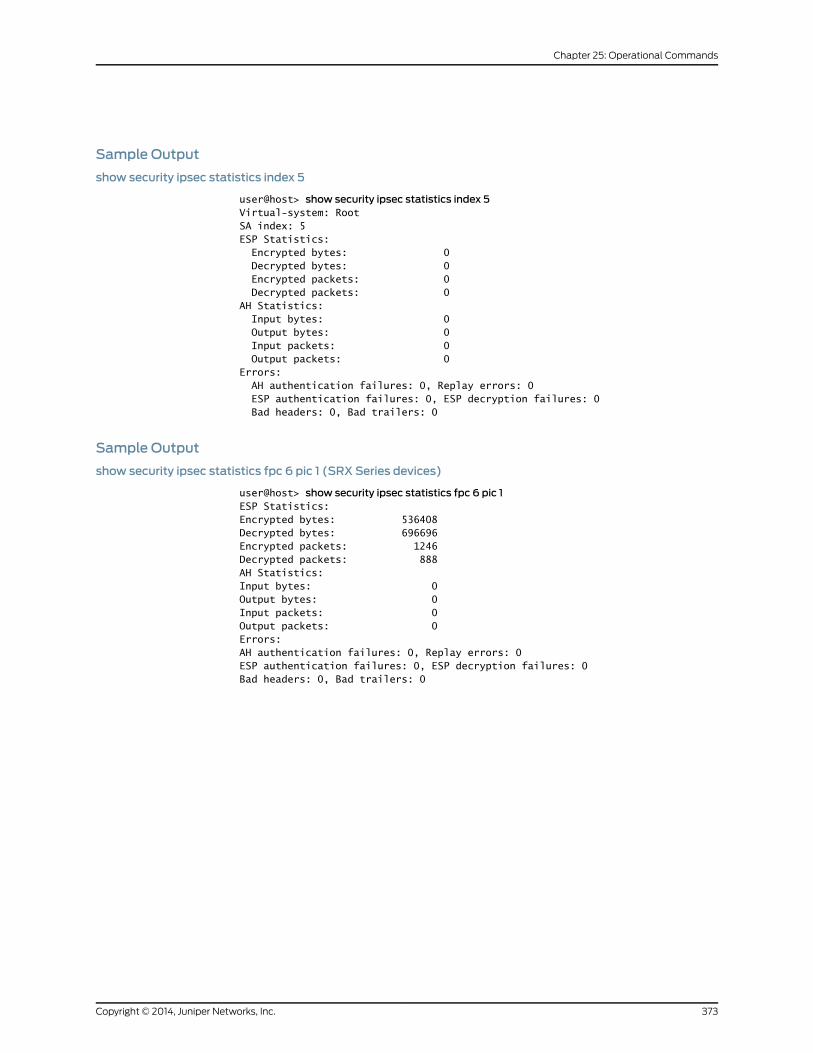
Sample Output
show security ipsec statistics index 5
user@host> show security ipsec statistics index 5Virtual-system: RootSA index: 5ESP Statistics: Encrypted bytes: 0 Decrypted bytes: 0 Encrypted packets: 0 Decrypted packets: 0AH Statistics: Input bytes: 0 Output bytes: 0 Input packets: 0 Output packets: 0Errors: AH authentication failures: 0, Replay errors: 0 ESP authentication failures: 0, ESP decryption failures: 0 Bad headers: 0, Bad trailers: 0
Sample Output
show security ipsec statistics fpc 6 pic 1 (SRX Series devices)
user@host> show security ipsec statistics fpc 6 pic 1ESP Statistics:Encrypted bytes: 536408Decrypted bytes: 696696Encrypted packets: 1246Decrypted packets: 888AH Statistics:Input bytes: 0Output bytes: 0Input packets: 0Output packets: 0Errors:AH authentication failures: 0, Replay errors: 0ESP authentication failures: 0, ESP decryption failures: 0Bad headers: 0, Bad trailers: 0
373Copyright © 2014, Juniper Networks, Inc.
Chapter 25: Operational Commands

Copyright © 2014, Juniper Networks, Inc.374
IPsec VPNs Feature Guide for Security Devices

PART 4
Index
• Index on page 377
375Copyright © 2014, Juniper Networks, Inc.

Copyright © 2014, Juniper Networks, Inc.376
IPsec VPNs Feature Guide for Security Devices
Index
Symbols#, comments in configuration statements...................xvi
( ), in syntax descriptions....................................................xvi
3DES...............................................................................................9
< >, in syntax descriptions...................................................xvi
[ ], in configuration statements.........................................xvi
{ }, in configuration statements........................................xvi
| (pipe), in syntax descriptions..........................................xvi
Aaddress statement
(IKE Gateway)..............................................................246
Advanced Encryption Standard (AES).............................9
AES.................................................................................................9
aggressive mode.....................................................................20
algorithm statement..........................................................290
always-send statement....................................................246
attacks
replay...................................................................................21
audible-alarm........................................................................233
authentication
algorithms...........................................................................8
authentication statement..................................................291
authentication-algorithm statement..................247, 292
authentication-method statement..............................248
AutoKey IKE VPN.......................................................................7
management......................................................................7
Bbind-interface statement..................................................293
braces, in configuration statements................................xvi
brackets
angle, in syntax descriptions.....................................xvi
square, in configuration statements.......................xvi
Ccertificate statement..........................................................249
certificates....................................................................................7
clear security ike respond-bad-spi-count
command...........................................................................340
clear security ike security-associations
command............................................................................341
clear security ipsec security-associations
command...........................................................................343
clear security ipsec statistics command.....................345
comments, in configuration statements.......................xvi
connections-limit statement..........................................250
container statement............................................................251
conventions
text and syntax................................................................xv
cryptographic-self-test statement...............................329
curly braces, in configuration statements.....................xvi
customer support..................................................................xvii
contacting JTAC.............................................................xvii
DData Encryption Standard (DES).......................................9
dead-peer-detection statement....................................252
decryption-failures statement........................................330
DES.................................................................................................9
destination-ip statement..................................................293
df-bit statement...................................................................294
dh-group statement............................................................253
Diffie-Hellman............................................................................7
distinguished-name statement......................................254
documentation
comments on.................................................................xvii
dynamic statement.............................................................255
Eencryption algorithms.............................................................9
encryption statement.........................................................295
encryption-algorithm statement.........................256, 296
encryption-failures statement.........................................331
ESP.............................................................................................8, 9
establish-tunnels statement...........................................297
external-interface statement
(IKE Gateway).....................................................257, 283
(Manual Security Association)...............................297
Ffirewall filters
statistics
clearing ..................................................................352
font conventions......................................................................xv
377Copyright © 2014, Juniper Networks, Inc.
Ggateway statement.............................................................298
(IKE).................................................................................258
(Manual Security Association)..............................298
Hhash-based message authentication code....................8
HMAC.............................................................................................8
hostname statement..........................................................259
hub-and-spoke.........................................................................31
Iidle-time statement............................................................299
IKE....................................................................................................7
Phase 1 proposals
predefined.................................................................18
Phase 2 proposals
predefined...............................................................20
proxy IDs............................................................................20
ike statement
(IPsec VPN)........................................................262, 300
(Security).......................................................................260
ike-phase1-failures statement.........................................333
ike-phase2-failures statement.......................................334
ike-policy statement...........................................................263
ike-user-type statement...................................................264
inet statement.......................................................................265
inet6 (IKE Gateway) statement.....................................265
install-interval statement..................................................301
interval statement
(IKE).................................................................................266
IPsec
SAs.............................................................................3, 9, 20
security protocols
Authentication Header (AH)...............................8
Encapsulating Security Protocol (ESP)..........8
tunnel....................................................................................3
tunnel mode......................................................................12
tunnel negotiation............................................................9
ipsec statement....................................................................302
ipsec-policy statement......................................................303
ipsec-vpn statement
(Security Flow)............................................................304
Kkey-generation-self-test statement.............................332
Llifetime-kilobytes statement...........................................304
lifetime-seconds statement
IKE.....................................................................................266
IPsec.................................................................................305
load-distribution statement............................................305
local statement....................................................................306
local-certificate statement...............................................267
local-identity statement...................................................268
Mmain mode.................................................................................19
manual key management
overview...............................................................................6
manual statement...............................................................307
manuals
comments on.................................................................xvii
MD5................................................................................................8
Message Digest version 5 (MD5)........................................8
mode statement
(Policy)............................................................................269
modes
aggressive.........................................................................20
main.....................................................................................19
tunnel...................................................................................12
modulus.........................................................................................7
NNAT
traversal.............................................................................49
nat-keepalive statement...................................................270
NAT-T..........................................................................................49
no-anti-replay statement.................................................308
no-nat-traversal statement.............................................270
non-cryptographic-self-test statement......................335
Ooptimized statement..........................................................308
Pparentheses, in syntax descriptions................................xvi
peer-certificate-type statement...........................271, 309
Perfect Forward Secrecy See PFS
perfect-forward-secrecy statement..............................310
PFS................................................................................................21
Phase 1.........................................................................................18
proposals...........................................................................18
proposals, predefined...................................................18
Phase 2.......................................................................................20
proposals..........................................................................20
proposals, predefined..................................................20
Copyright © 2014, Juniper Networks, Inc.378
IPsec VPNs Feature Guide for Security Devices

policy statement
(IKE)..................................................................................272
policy-based VPN...................................................................29
policy-based VPN configuration example...................125
policy-based VPN with both initiator and responder
behind NAT configuration example...........................142
potential-violation...............................................................234
authentication..............................................................234
decryption......................................................................234
encryption......................................................................234
ikephase1.........................................................................234
ikephase2........................................................................234
replayattack...................................................................234
self-test...........................................................................234
pre-shared-key statement.......................................273, 312
preshared key..............................................................................7
proposal statement....................................................274, 313
proposal-set statement
(IKE)..................................................................................275
(IPsec)..............................................................................314
proposals
Phase 1................................................................................18
Phase 2..............................................................................20
proposals statement..................................................276, 315
protocol statement
(IPsec)..............................................................................316
(Manual Security Association)................................317
proxy IDs.....................................................................................20
proxy-identity statement...................................................318
Rremote statement.................................................................319
remote-identity statement................................................277
replay protection......................................................................21
replay-attacks statement.................................................336
request security ike debug-disable command..........347
request security ike debug-enable command..........348
respond-bad-spi statement.............................................278
route-based VPN....................................................................25
route-based VPN configuration example...............61, 79
route-based VPN with only responder behind NAT
configuration example.....................................................95
SSA parameters............................................................................9
SAs...............................................................................................20
Secure Hash Algorithm-1........................................................8
security
alarms....................................................................329, 333
service statement
(Security IPsec)............................................................319
session affinity
VPN............................................................................47, 239
session-affinity statement...............................................320
SHA-1.............................................................................................8
show security ike active-peer command....................349
show security ike debug-status command...............350
show security ike pre-shared-key command.............351
show security ike security-associations
command............................................................................352
show security ike tunnel-map.........................................359
show security ipsec inactive-tunnels
command...........................................................................360
show security ipsec next-hop-tunnels
command...........................................................................363
show security ipsec security-associations
command...........................................................................364
show security ipsec statistics command.....................371
source-interface statement.............................................320
spi statement..........................................................................321
SPUs
VPN session affinity.............................................47, 239
support, technical See technical support
syntax conventions.................................................................xv
Ttechnical support
contacting JTAC.............................................................xvii
threshold statement............................................................279
traceoptions statement
(IKE).................................................................................280
(IPsec)..............................................................................322
transport mode.........................................................................12
Triple DES.....................................................................................9
trusted-ca statement................................................282, 323
tunnel mode
overview..............................................................................12
Uuser-at-hostname statement.........................................283
Vvirtual router....................................................................26, 120
configure st0 interface...............................................120
support in route-based VPNs....................................26
vpn statement.......................................................................324
vpn-monitor statement.....................................................325
vpn-monitor-options statement....................................326
379Copyright © 2014, Juniper Networks, Inc.
Index

VPNs
aggressive mode............................................................20
AutoKey IKE.........................................................................7
Diffie-Hellman exchange...............................................7
Diffie-Hellman groups....................................................7
enabling session affinity...........................................239
hub-and-spoke configuration example................171
main mode........................................................................19
Phase 1................................................................................18
Phase 2..............................................................................20
policy-based....................................................................29
policy-based configuration example....................125
policy-based initiator responder and behind
NAT configuration example.................................142
replay protection.............................................................21
route-based......................................................................25
route-based configuration example.................61, 79
route-based responder behind NAT
configuration example............................................95
session affinity.................................................................47
Wwildcard statement.............................................................284
Xxauth statement...................................................................285
Copyright © 2014, Juniper Networks, Inc.380
IPsec VPNs Feature Guide for Security Devices