ipmi cim mapping guideline-v0 60 - intel · ipmi cim mapping guideline iii 49 authors’ grant of...
TRANSCRIPT

2/6/2005
- IPMI -
IPMI CIM Mapping Guideline Document Revision 0.60
2/6/2006
Intel Hewlett-Packard Dell Avocent

IPMI CIM Mapping Guideline
ii
Intellectual Property Agreement and Disclaimers 1 The information contained in this IPMI CIM Mapping Guideline (“Mapping Guideline”) represents the current view 2 of Intel Corporation (“Intel”), Dell Incorporated (“Dell”), Avocent Corporation (“Avocent”) and Hewlett 3 Packard Company (“Hewlett Packard”) on issues discussed as of the date of publication. Because Intel, Dell, 4 Avocent and Hewlett Packard must respond to changing market conditions, it should not be interpreted to be a 5 commitment on the part of Intel, Dell, Avocent and Hewlett Packard, and Intel, Dell, Avocent and Hewlett Packard 6 cannot guarantee the accuracy of any information presented. This Mapping Guideline is for informational purposes 7 only. 8 Intel, Dell, Avocent and Hewlett Packard (collectively referred to herein as the “Authors”) provide this Mapping 9 Guideline under the following licensing terms. This Agreement to Royalty Free Licensing Terms for IPMI CIM 10 Mapping Guidelines Agreement and the corresponding Intellectual Property Agreement and Disclaimers for the 11 Mapping Guideline makes reference to the IPMI CIM Mapping Guideline. This Agreement to Royalty Free 12 Licensing Terms for IPMI CIM Mapping Guidelines Agreement and the corresponding Intellectual Property 13 Agreement and Disclaimers does not replace or supersede any of the Promoter, Contributor, or Adopter agreements, 14 Intellectual Property agreements, or disclaimers for any IPMI specifications, including, but not limited to, the 15 agreements for the Intelligent Platform Management Interface Specifications and the Intelligent Platform 16 Management Interface Second Generation Specifications. 17 THE MAPPING GUIDELINE IS PROVIDED “AS-IS” AND THE AUTHORS DO NOT MAKE ANY 18 REPRESENTATION OR WARRANTY REGARDING THE MAPPING GUIDELINE OR ANY PRODUCT OR 19 ITEM DEVELOPED BASED ON THE MAPPING GUIDELINE. THE AUTHORS DISCLAIM ALL EXPRESS 20 AND IMPLIED WARRANTIES, INCLUDING BUT NOT LIMITED TO THE IMPLIED WARRANTIES OF 21 MERCHANTABILITY, FITNESS FOR A PARTICULAR PURPOSE, AND FREEDOM FROM 22 INFRINGEMENT. WITHOUT LIMITING THE GENERALITY OF THE FOREGOING, THE AUTHORS DO 23 NOT MAKE ANY WARRANTY OF ANY KIND THAT ANY ITEM DEVELOPED BASED ON THE MAPPING 24 GUIDELINE, OR ANY PORTION OF THEREOF, WILL NOT INFRINGE ANY COPYRIGHT, PATENT, 25 TRADE SECRET, OR OTHER INTELLECTUAL PROPERTY RIGHT OF ANY PERSON OR ENTITY IN ANY 26 COUNTRY EXCEPT AS PROVIDED FOR BELOW. IT IS YOUR RESPONSIBILITY TO SEEK LICENSES 27 FOR SUCH INTELLECTUAL PROPERTY RIGHTS WHERE APPROPRIATE. 28 THE AUTHORS SHALL NOT BE LIABLE FOR ANY DAMAGES ARISING OUT OF OR IN CONNECTION 29 WITH THE USE OF THE MAPPING GUIDELINE, INCLUDING LIABILITY FOR LOST PROFIT, BUSINESS 30 INTERRUPTION, OR ANY OTHER DAMAGES WHATSOEVER. 31 Mapping Guideline Definitions. “Necessary Claims” shall mean those claims of all patents and patent applications 32 throughout the world, excluding any claims to enabling technologies that may be necessary to make or use any 33 implementation of the Mapping Guideline but are not themselves expressly set forth in the Mapping Guideline (e.g., 34 semiconductor manufacturing technology, basic operating system technology, etc.), which a party has the right to 35 grant licenses of the scope granted herein without such grant or the exercise of rights thereunder resulting in 36 payment of royalties or other consideration to third parties (except payment to affiliates) and which are necessarily 37 infringed by an implementation of this Mapping Guideline pursuant to the preceding and following sections of this 38 Intellectual Property Agreement, where such infringement could not have been avoided by another technically 39 reasonable non-infringing implementation of the Mapping Guideline. 40 41 Grants of Licenses. Each Author hereby grants, to each of the other Authors and all implementers of the Mapping 42 Guideline, a nonexclusive, perpetual, royalty-free, nontransferable, nonsublicenseable (except as part of transfer of 43 an end user product), worldwide license under its Necessary Claims to make, have made, use, import, offer to sell 44 and sell and otherwise distribute the portions of products, whether hardware, software, or combination of hardware 45 and software, which implement all or part of the Mapping Guideline for the sole purpose of mapping the IPMI 1.5 46 Specification into a DMTF CIM specification. No license is granted hereunder to any person or entity to implement 47 either IPMI or DMTF specifications. 48

IPMI CIM Mapping Guideline
iii
Authors’ grant of the above license to each implementer is subject to the implementer’s agreement to grant, upon 49 request, a nonexclusive, perpetual, royalty-free, nontransferable, nonsublicenseable (except as part of transfer of an 50 end user product), worldwide license to the Authors, under such implementer’s Necessary Claims to make, have 51 made, use, import, offer to sell and sell and otherwise distribute the portions of products, whether hardware, 52 software, or combination of hardware and software, which implement all or part of the same version of the 53 Mapping Guideline for the sole purpose of mapping the IPMI 1.5 Specification into a DMTF CIM specification. 54 Document Feedback and Contributions. Any feedback or other contribution by any person or entity in any 55 country that may be incorporated into this document can only be provided if the contributor agrees in writing to the 56 IPMI CIM Mapping Feedback Agreement. The IPMI CIM Mapping Feedback Agreement can be obtained by 57 contacting one of the Authors. 58 Representation and warranties. Each Author represents and warrants that to the actual knowledge of the Author’s 59 named representative (1) the Author has full rights to make the contributions made by the Author to the Mapping 60 Guideline, (2) no other party has provided feedback or contributed to the Mapping Guideline through the Author and 61 that any party doing so in the future must have agreed to do so as a Contributing Party by executing the IPMI CIM 62 Mapping Feedback, and (3) the exercise of the licenses granted hereunder by the Author with regard to the Author’s 63 contributions will not, to the knowledge of the Author, violate any third party copyright or trade secrets. 64 Copyright. The Authors hereby grant a nonexclusive, perpetual, irrevocable, non-transferable, worldwide royalty 65 free copyright license, to make copies, distribute, publish and display the Mapping Guideline so long as the below 66 copyright notice is retained with each copy of the Mapping Guideline. 67 68 © 2004–2005 Intel Corporation, Dell Incorporated, Avocent Corporation and Hewlett Packard Company. All rights 69 reserved. 70 This document is not for sale. 71 72 To obtain additional copies of this this document, please download the source files from the web sites at 73 http://www.intel.com/design/servers/ipmi 74 DMTF is a not-for-profit association of industry members dedicated to promoting enterprise and systems management and interoperability. Members and non-members may reproduce DMTF specifications and documents for uses consistent with this purpose, provided that correct attribution is given. As DMTF specifications may be revised from time to time, the particular version and release date should always be noted. Implementation of certain elements of DMTF standards or proposed standards may be subject to third party patent rights, including provisional patent rights (herein “patent rights”). DMTF makes no representations to users of the standard as to the existence of such rights, and is not responsible to recognize, disclose, or identify any or all such third party patent right, owners or claimants, nor for any incomplete or inaccurate identification or disclosure of such rights, owners or claimants. DMTF shall have no liability to any party, in any manner or circumstance, under any legal theory whatsoever, for failure to recognize, disclose, or identify any such third party patent rights, or for such party’s reliance on the standard or incorporation thereof in its product, protocols or testing procedures. DMTF shall have no liability to any party implementing such standard, whether such implementation is foreseeable or not, nor to any patent owner or claimant, and shall have no liability or responsibility for costs or losses incurred if a standard is withdrawn or modified after publication, and shall be indemnified and held harmless by any party implementing the standard from any and all claims of infringement by a patent owner for such implementations. For information about patents held by third-parties which have notified the DMTF that, in their opinion, such patent may relate to or impact implementations of DMTF standards, visit http://www.dmtf.org/about/policies/disclosures.php. 75

IPMI CIM Mapping Guideline
iv
Abstract The Common Information Model (CIM)1 is an object-oriented information model defined by the 76 Distributed Management Task Force (DMTF), which provides a conceptual framework for 77 describing management data. 78
This document defines CIM mappings for specific areas of server management. This includes 79 the behavioral conventions required for interoperability. This is intended to be a consistent, 80 cross-vendor mapping of the Intelligent Platform Management Interface (IPMI)2 to CIM. 81
Referenced Standards 82 Cross-references to standards being published or developed by DMTF (or other organizations), 83 or reproduction of information from published standards, are for the purpose of interoperability 84 with those standards and for defining functionality needed for interoperability. Such cross-85 references are not for the purpose of using copyrighted material from those standards. All such 86 referenced content remains outside of the scope of this document. See Reference Documents for 87 additional information. 88
Change History 89 Version Date Editor Description
0.60 February 06, 2006
Jon R. Hass, Dell Inc.
Added the following major sections:
- IPMI Entity Mapping
- IPMI Watchdog Mapping
- IPMI Software Identity Mapping
Updated Section 2 – Common Steps for Mapping Process.
Changes to Sensor property mappings.
Changes to Log property mappings.
Changes to User ID Management mappings.
Changes to BMC mappings.
Changes to Versioning mapping behavior.
Open Issues 90 91
1 Common Information Model (CIM) Specification, V2.2, June 14, 1999,
http://www.dmtf.org/standards/standard_cim.php 2 Intelligent Platform Management Interface Specification, V1.5, February 20, 2002,
http://www.intel.com/design/servers/ipmi
IPMI CIM Mapping Guideline
v
Outline Table of Contents 92
Document Revision 0.60 2/6/2006......................................................................................................... i 93 Intellectual Property Agreement and Disclaimers ................................................................................... ii 94 Abstract ........................................................................................................................................................ iv 95 1 Introduction ............................................................................................................................................ 1 96 2 Common Steps for Mapping Process ..................................................................................................... 7 97 3 IPMI Sensor Mapping .......................................................................................................................... 20 98 4 IPMI Log Mapping............................................................................................................................... 40 99 5 IPMI Commands Mapping ................................................................................................................... 52 100 6 IPMI Power Control Mapping.............................................................................................................. 55 101 7 IPMI User ID Management Mapping................................................................................................... 61 102 8 IPMI BMC Mapping ............................................................................................................................ 69 103 9 IPMI Versioning Mapping.................................................................................................................... 79 104 10 IPMI Entity Mapping ........................................................................................................................... 83 105 11 IPMI Watchdog Mapping ................................................................................................................... 126 106 12 IPMI Software Identity Mapping ....................................................................................................... 136 107 13 Acknowledgments .............................................................................................................................. 140 108
109
Table of Contents 110
Abstract ........................................................................................................................................................ iv 111 Change History ............................................................................................................................................ iv 112 Open Issues .................................................................................................................................................. iv 113 1 Introduction ............................................................................................................................................ 1 114
1.1 Target Audience ............................................................................................................................ 1 115 1.2 Conventions................................................................................................................................... 1 116 1.3 Reference Documents ................................................................................................................... 1 117 1.4 Terminology .................................................................................................................................. 2 118 1.5 Acronyms and Abbreviations........................................................................................................ 2 119 1.6 Editorial Conventions.................................................................................................................... 3 120 1.7 Notational Conventions................................................................................................................. 4 121 1.8 Referenced Standards .................................................................................................................... 5 122
2 Common Steps for Mapping Process ..................................................................................................... 7 123 2.1 Discovering IPMI Interfaces ......................................................................................................... 7 124
2.1.1 System Interfaces ................................................................................................................ 7 125 2.1.2 Remote Interfaces ............................................................................................................... 7 126
2.2 Internal Interfaces.......................................................................................................................... 9 127 2.3 Discovery and Enumeration of IPMI Entity, Sensor, and FRU Information and 128
Associations .................................................................................................................................. 9 129 2.3.1 Recommendations on the access and use of SDR Info....................................................... 9 130
2.4 Entity Discovery.......................................................................................................................... 10 131
IPMI CIM Mapping Guideline
vi
2.4.1 Entity presence rules ......................................................................................................... 10 132 2.4.1.1 Explicit by Entity Association ................................................................................ 11 133 2.4.1.2 Explicit by Sensor SDR or Event SDR................................................................... 11 134 2.4.1.3 Explicit by FRU Device Locator Record................................................................ 11 135 2.4.1.4 Implicit by Sensor Type.......................................................................................... 12 136 2.4.1.5 Implicit by FRU Data ............................................................................................. 12 137
2.5 Sensor Discovery......................................................................................................................... 13 138 2.5.1 Sensor Presence Rules ...................................................................................................... 13 139
2.6 FRU Device Discovery ............................................................................................................... 14 140 2.6.1 By BMC Primary FRU Device ......................................................................................... 14 141 2.6.2 By Management Controller Device Locator Record ........................................................ 14 142 2.6.3 By FRU Device Locator Record....................................................................................... 15 143
2.7 Discovering Sensor, Entity, & FRU Associations....................................................................... 15 144 2.8 Instantiating CIM Objects ........................................................................................................... 17 145
2.8.1 Sensor Instantiation : ........................................................................................................ 17 146 2.8.1.1 Sensor state/reading rules ....................................................................................... 18 147
2.8.2 Entity Instantiation............................................................................................................ 18 148 2.8.3 FRU instantiation.............................................................................................................. 18 149
3 IPMI Sensor Mapping .......................................................................................................................... 20 150 3.1 Introduction ................................................................................................................................. 20 151 3.2 Instance Examples....................................................................................................................... 21 152 3.3 Mapping Requirements ............................................................................................................... 21 153
3.3.1 Handling Sensor Specific Offsets ..................................................................................... 21 154 3.4 CIM_Sensor Mapping ................................................................................................................. 22 155
3.4.1 CIM_Sensor Methods ....................................................................................................... 22 156 3.4.1.1 Method: Reset() ...................................................................................................... 22 157 3.4.1.2 Method: RequestStateChange................................................................................. 23 158
3.4.2 CIM_Sensor Properties..................................................................................................... 23 159 3.4.2.1 CIM_Sensor.SystemCreationClassName ............................................................... 24 160 3.4.2.2 CIM_Sensor.SystemName...................................................................................... 24 161 3.4.2.3 CIM_Sensor.CreationClassName ........................................................................... 25 162 3.4.2.4 CIM_Sensor.DeviceID ........................................................................................... 25 163 3.4.2.5 CIM_Sensor.ElementName and CIM_Sensor.Name ............................................. 26 164 3.4.2.6 CIM_Sensor.SensorType and CIM_Sensor.OtherSensorTypeDescription ............ 27 165 3.4.2.7 CIM_Sensor.PossibleStates .................................................................................... 32 166 3.4.2.8 CIM_Sensor.CurrentState....................................................................................... 33 167 3.4.2.9 CIM_Sensor.Caption .............................................................................................. 33 168 3.4.2.10 CIM_Sensor.Description ...................................................................................... 34 169 3.4.2.11 CIM_Sensor.PollingInterval ................................................................................. 34 170 3.4.2.12 CIM_Sensor.HealthState ...................................................................................... 34 171 3.4.2.13 CIM_Sensor.OperationalStatus ............................................................................ 34 172
3.5 CIM_NumericSensor Mapping ................................................................................................... 34 173 3.5.1 CIM_NumericSensor.Properties....................................................................................... 35 174
3.5.1.1 NumericSensor.CurrentReading ............................................................................. 36 175 3.5.1.2 NumericSensor.UnitModifier, BaseUnits, And RateUnits ..................................... 36 176 3.5.1.3 NumericSensor.NominalReading ........................................................................... 37 177 3.5.1.4 NumericSensor.NormalMax ................................................................................... 37 178 3.5.1.5 NumericSensor.NormalMin.................................................................................... 37 179 3.5.1.6 NumericSensor.MaxReadable ................................................................................ 37 180 3.5.1.7 NumericSensor.MinReadable ................................................................................. 37 181 3.5.1.8 NumericSensor.Resolution ..................................................................................... 37 182 3.5.1.9 NumericSensor.Accuracy ....................................................................................... 38 183
IPMI CIM Mapping Guideline
vii
3.5.1.10 NumericSensor.IsLinear ....................................................................................... 38 184 3.5.1.11 NumericSensor.Hysteresis.................................................................................... 38 185 3.5.1.12 NumericSensor.SupportedThresholds .................................................................. 38 186 3.5.1.13 NumericSensor.EnableThresholds........................................................................ 38 187 3.5.1.14 NumericSensor.SettableThresholds...................................................................... 38 188 3.5.1.15 NumericSensor.LowerThresholdNonCritical ....................................................... 38 189 3.5.1.16 NumericSensor.UpperThresholdNonCritical........................................................ 39 190 3.5.1.17 NumericSensor.LowerThresholdCritical .............................................................. 39 191 3.5.1.18 NumericSensor.UpperThresholdCritical .............................................................. 39 192 3.5.1.19 NumericSensor.LowerThresholdFatal .................................................................. 39 193 3.5.1.20 NumericSensor.UpperThresholdFatal .................................................................. 39 194
4 IPMI Log Mapping............................................................................................................................... 40 195 4.1 Introduction ................................................................................................................................. 40 196 4.2 Instance Diagrams ....................................................................................................................... 41 197 4.3 Mapping Requirements ............................................................................................................... 41 198
4.3.1 Associating SEL with SDR............................................................................................... 41 199 4.4 CIM_RecordLog Mapping.......................................................................................................... 42 200
4.4.1 CIM_RecordLog.Methods ................................................................................................ 42 201 4.4.1.1 Method: ClearLog................................................................................................... 42 202 4.4.1.2 Method: RequestStateChange................................................................................. 43 203
4.4.2 CIM_RecordLog.Properties.............................................................................................. 43 204 4.4.2.1 CIM_RecordLog.InstanceID .................................................................................. 44 205 4.4.2.2 CIM_RecordLog.Name .......................................................................................... 44 206 4.4.2.3 CIM_RecordLog.MaxNumberOfRecords .............................................................. 44 207 4.4.2.4 CIM_RecordLog. CurrentNumberOfRecords ........................................................ 45 208 4.4.2.5 CIM_RecordLog.EnabledState............................................................................... 45 209 4.4.2.6 CIM_RecordLog.HealthState ................................................................................. 45 210 4.4.2.7 CIM_RecordLog.OperationalStatus ....................................................................... 45 211 4.4.2.8 CIM_RecordLog. Caption ...................................................................................... 45 212 4.4.2.9 CIM_RecordLog. Description ................................................................................ 45 213 4.4.2.10 CIM_RecordLog. ElementName .......................................................................... 45 214
4.5 CIM_LogRecord Mapping.......................................................................................................... 45 215 4.5.1 CIM_LogRecord Methods................................................................................................ 45 216 4.5.2 CIM_LogRecord Properties.............................................................................................. 46 217
4.5.2.1 CIM_LogRecord.LogCreationClassName.............................................................. 46 218 4.5.2.2 CIM_LogRecord.LogName.................................................................................... 46 219 4.5.2.3 CIM_LogRecord.CreationClassName.................................................................... 46 220 4.5.2.4 CIM_LogRecord.RecordID .................................................................................... 47 221 4.5.2.5 CIM_LogRecord. MessageTimestamp................................................................... 47 222 4.5.2.6 CIM_LogRecord.RecordFormat............................................................................. 47 223 4.5.2.7 CIM_LogRecord. RecordData................................................................................ 48 224 4.5.2.8 CIM_LogRecord.Caption ....................................................................................... 48 225 4.5.2.9 CIM_LogRecord.Description ................................................................................. 51 226
5 IPMI Commands Mapping ................................................................................................................... 52 227 5.1 Introduction ................................................................................................................................. 52 228 5.2 Mapping Requirements ............................................................................................................... 52 229
5.2.1 IPMI Commands Limitations ........................................................................................... 52 230 5.3 CIM_CommandService Mapping ............................................................................................... 52 231
5.3.1 CIM_CommandService.Methods ..................................................................................... 52 232 5.3.1.1 Method: ExecuteOEMCommand ........................................................................... 52 233
5.3.2 CIM_CommandService.Properties ................................................................................... 53 234

IPMI CIM Mapping Guideline
viii
5.3.2.1 CIM_ CommandService.SystemCreationClassName............................................. 54 235 5.3.2.2 CIM_ CommandService.SystemName................................................................... 54 236 5.3.2.3 CIM_CommandService.CreationClassName ......................................................... 54 237 5.3.2.4 CIM_ CommandService.Name............................................................................... 54 238 5.3.2.5 CIM_ CommandService.IANA .............................................................................. 54 239 5.3.2.6 CIM_ CommandService. Caption........................................................................... 54 240 5.3.2.7 CIM_ CommandService. Description..................................................................... 54 241
6 IPMI Power Control Mapping.............................................................................................................. 55 242 6.1 Introduction ................................................................................................................................. 55 243 6.2 Instance Diagrams ....................................................................................................................... 55 244 6.3 Mapping Requirements ............................................................................................................... 56 245 6.4 CIM_PowerManagementService Mapping................................................................................. 56 246
6.4.1 CIM_PowerManagementService Methods....................................................................... 56 247 6.4.1.1 Method: PowerManagementService.SetPowerState( ) ........................................... 56 248 6.4.1.2 Method: PowerManagementService.StartService()................................................ 57 249 6.4.1.3 Method: PowerManagementServce.StopServce() .................................................. 57 250 6.4.1.4 Method: PowerManagementService.RequestStateChange() .................................. 57 251
6.4.2 CIM_PowerManagementService.Properties..................................................................... 57 252 6.4.2.1 CIM_PowerManagementService.CreationClassName........................................... 58 253 6.4.2.2 CIM_PowerManagementService.Name ................................................................. 58 254
6.5 CIM_PowerManagementCapabilities Mapping.......................................................................... 58 255 6.5.1 CIM_PowerManagementCapabilities Methods................................................................ 58 256 6.5.2 CIM_PowerManagementCapabilities Properties.............................................................. 58 257
6.5.2.1 CIM_PowerManagementCapabilities.PowerCapabilities ...................................... 59 258 6.6 CIM_AssociatedPowerManagementService Mapping ............................................................... 59 259
6.6.1 CIM_AssociatedPowerManagementService Methods ..................................................... 59 260 6.6.2 CIM_AssociatedPowerManagementService Properties ................................................... 59 261
6.6.2.1 CIM_AssociatedPowerManagementService.PowerState ....................................... 60 262 6.6.2.2 CIM_AssociatedPowerManagementService.OtherPowerState .............................. 60 263 6.6.2.3 CIM_AssociatedPowerManagementService.PowerOnTime.................................. 60 264
7 IPMI User ID Management Mapping................................................................................................... 61 265 7.1 Introduction ................................................................................................................................. 61 266 7.2 Instance Diagrams ....................................................................................................................... 61 267 7.3 Mapping Requirements ............................................................................................................... 62 268
7.3.1 Mapping IPMI User ID’s .................................................................................................. 62 269 7.3.2 Mapping IPMI Access Privileges ..................................................................................... 62 270 7.3.3 Modeling CIM_AuthorizedPrivilege ................................................................................ 63 271
7.4 CIM_Account Mapping .............................................................................................................. 63 272 7.4.1 CIM_Account Methods .................................................................................................... 63 273 7.4.2 CIM_Account Properties .................................................................................................. 63 274
7.4.2.1 CIM_Account.SystemCreationClassName............................................................. 64 275 7.4.2.2 CIM_Account.SystemName................................................................................... 64 276 7.4.2.3 CIM_Account.CreationClassName ........................................................................ 65 277 7.4.2.4 CIM_Account.Name............................................................................................... 65 278 7.4.2.5 CIM_Account.UserID............................................................................................. 65 279 7.4.2.6 CIM_Account.UserPassword ................................................................................. 65 280 7.4.2.7 CIM_Account.OperationalStatus............................................................................ 65 281 7.4.2.8 CIM_Account.StatusDescriptions .......................................................................... 66 282
7.5 CIM_Group Mapping.................................................................................................................. 66 283 7.5.1 CIM_Group Methods........................................................................................................ 66 284 7.5.2 CIM_Group Properties ..................................................................................................... 66 285

IPMI CIM Mapping Guideline
ix
7.5.2.1 CIM_Group.CreationClassName............................................................................ 66 286 7.5.2.2 CIM_Group.Name .................................................................................................. 66 287
7.6 CIM_AuthorizedPrivilege Mapping............................................................................................ 67 288 7.6.1 CIM_AuthorizedPrivilege Methods.................................................................................. 67 289 7.6.2 CIM_AuthorizedPrivilege Properties ............................................................................... 67 290
7.6.2.1 CIM_AuthorizedPrivilege.InstanceID.................................................................... 67 291 7.6.2.2 CIM_AuthorizedPrvilege.PrivilegeGranted ........................................................... 68 292 7.6.2.3 CIM_AuthorizedPrivilege.Activities ...................................................................... 68 293 7.6.2.4 CIM_AuthorizedPrivilege.ElementName............................................................... 68 294
8 IPMI BMC Mapping ............................................................................................................................ 69 295 8.1 Introduction ................................................................................................................................. 69 296 8.2 Instance Diagrams ....................................................................................................................... 69 297 8.3 Mapping Requirements ............................................................................................................... 70 298 8.4 CIM_AdminDomain Mapping .................................................................................................... 71 299
8.4.1 CIM_AdminDomain Methods .......................................................................................... 71 300 8.4.1.1 Method: AdminDomain.RequestStateChange() ..................................................... 71 301
8.4.2 CIM_AdminDomain.Properties........................................................................................ 71 302 8.4.2.1 CIM_AdminDomain.CreationClassName.............................................................. 72 303 8.4.2.2 CIM_AdminDomain.Name .................................................................................... 72 304
8.5 CIM_ComputerSystem Mapping ................................................................................................ 72 305 8.5.1 CIM_ComputerSystem Methods ...................................................................................... 72 306
8.5.1.1 Method: ComputerSystem.RequestStateChange() ................................................. 72 307 8.5.2 CIM_ComputerSystem Properties .................................................................................... 73 308
8.5.2.1 CIM_ComputerSystem.Name................................................................................. 74 309 8.5.2.2 CIM_ComputerSystem.CreationClassName .......................................................... 75 310 8.5.2.3 CIM_ComputerSystem.Dedicated.......................................................................... 75 311 8.5.2.4 CIM_ComputerSystem.Roles ................................................................................. 75 312 8.5.2.5 CIM_ComputerSystem.EnabledState ..................................................................... 76 313 8.5.2.6 CIM_ComputerSystem.HealthState ....................................................................... 76 314 8.5.2.7 CIM_ComputerSystem.OperationalStatus.............................................................. 76 315 8.5.2.8 CIM_ComputerSystem.NameFormat ..................................................................... 76 316 8.5.2.9 CIM_ComputerSystem.ElementName ................................................................... 76 317 8.5.2.10 CIM_ComputerSystem.IdentifyingDescriptions .................................................. 77 318 8.5.2.11 CIM_ComputerSystem.OtherIdentifyingInfo....................................................... 77 319 8.5.2.12 CIM_ComputerSystem.Caption ........................................................................... 77 320 8.5.2.13 CIM_ComputerSystem.Description ..................................................................... 77 321
9 IPMI Versioning Mapping.................................................................................................................... 79 322 9.1 Introduction ................................................................................................................................. 79 323 9.2 Instance Diagrams ....................................................................................................................... 79 324 9.3 Mapping Requirements ............................................................................................................... 80 325 9.4 CIM_RegisteredProfile Mapping ................................................................................................ 80 326
9.4.1 CIM_RegisteredProfile Methods ...................................................................................... 80 327 9.4.2 CIM_RegisteredProfile Properties.................................................................................... 80 328
9.4.2.1 CIM_RegisteredProfile.InstanceID ........................................................................ 81 329 9.4.2.2 CIM_RegisteredProfile.RegisteredOrganization .................................................... 81 330 9.4.2.3 CIM_RegisteredProfile.OtherRegisteredOrganization ........................................... 81 331 9.4.2.4 CIM_RegisteredProfile.RegisteredName ............................................................... 81 332 9.4.2.5 CIM_RegisteredProfile.RegisteredVersion ............................................................ 81 333
10 IPMI Entity Mapping ........................................................................................................................... 83 334 10.1 Introduction ................................................................................................................................. 83 335 10.2 Instance Diagrams ....................................................................................................................... 84 336
IPMI CIM Mapping Guideline
x
10.2.1 Example: System Board as Physical Parent...................................................................... 84 337 10.2.2 Example: Chassis as Physical Parent ................................................................................ 85 338
10.3 Mapping Requirements ............................................................................................................... 86 339 10.3.1 Mapping Entity ID’s to CIM Classes................................................................................ 86 340 10.3.2 Entity Instantiation Algorithm .......................................................................................... 88 341 10.3.3 Entity Instance Correlation ............................................................................................... 95 342
10.4 CIM_PhysicalPackage Mapping ................................................................................................. 95 343 10.4.1 CIM_PhysicalPackage Methods ....................................................................................... 95 344 10.4.2 CIM_PhysicalPackage Properties ..................................................................................... 95 345
10.4.2.1 CIM_PhysicalPackage.Tag................................................................................... 96 346 10.4.2.2 CIM_PhysicalPackage.CreationClassName ......................................................... 96 347 10.4.2.3 CIM_PhysicalPackage.PackageType ................................................................... 97 348 10.4.2.4 CIM_PhysicalPackage.Manufacturer ................................................................... 99 349 10.4.2.5 CIM_PhysicalPackage.Model............................................................................... 99 350 10.4.2.6 CIM_PhysicalPackage.PartNumber ..................................................................... 99 351 10.4.2.7 CIM_PhysicalPackage.SerialNumber................................................................... 99 352 10.4.2.8 CIM_PhysicalPackage.Name ............................................................................... 99 353 10.4.2.9 CIM_PhysicalPackage.HealthState .................................................................... 100 354 10.4.2.10 CIM_PhysicalPackage.OperationalStatus ........................................................ 100 355 10.4.2.11 CIM_PhysicalPackage.Description .................................................................. 100 356 10.4.2.12 CIM_PhysicalPackage.ElementName .............................................................. 100 357
10.5 CIM_Card Mapping .................................................................................................................. 100 358 10.5.1 CIM_Card Methods ........................................................................................................ 100 359 10.5.2 CIM_Card Properties ...................................................................................................... 100 360
10.5.2.1 CIM_Card.Tag.................................................................................................... 102 361 10.5.2.2 CIM_Card.CreationClassName .......................................................................... 102 362 10.5.2.3 CIM_Card.HostingBoard.................................................................................... 102 363 10.5.2.4 CIM_Card.PackageType..................................................................................... 102 364 10.5.2.5 CIM_Card.Manufacturer .................................................................................... 104 365 10.5.2.6 CIM_ Card.ManufacturerDate............................................................................ 104 366 10.5.2.7 CIM_ Card.PartNumber...................................................................................... 104 367 10.5.2.8 CIM_ Card.SerialNumber................................................................................... 104 368 10.5.2.9 CIM_ Card.Name ............................................................................................... 104 369 10.5.2.10 CIM_Card.HealthState ..................................................................................... 105 370 10.5.2.11 CIM_Card.OperationalStatus ........................................................................... 105 371 10.5.2.12 CIM_Card.Description ..................................................................................... 105 372 10.5.2.13 CIM_Card.ElementName ................................................................................. 105 373
10.6 CIM_Chip Mapping .................................................................................................................. 105 374 10.6.1 CIM_Chip Methods ........................................................................................................ 105 375 10.6.2 CIM_Chip Properties ...................................................................................................... 105 376
10.6.2.1 CIM_Chip.Tag.................................................................................................... 106 377 10.6.2.2 CIM_Chip.CreationClassName .......................................................................... 107 378 10.6.2.3 CIM_Chip.HealthState ....................................................................................... 107 379 10.6.2.4 CIM_Chip.OperationalStatus ............................................................................. 107 380 10.6.2.5 CIM_Chip.Description ....................................................................................... 107 381 10.6.2.6 CIM_Chip.ElementName ................................................................................... 107 382
10.7 CIM_Chassis Mapping.............................................................................................................. 107 383 10.7.1 CIM_Chassis Methods.................................................................................................... 107 384 10.7.2 CIM_Chassis Properties ................................................................................................. 107 385
10.7.2.1 CIM_Chassis.Tag ............................................................................................... 109 386 10.7.2.2 CIM_Chassis.CreationClassName...................................................................... 109 387 10.7.2.3 CIM_Chassis.ChassisPackageType.................................................................... 109 388
IPMI CIM Mapping Guideline
xi
10.7.2.4 CIM_ Chassis.PartNumber ................................................................................. 110 389 10.7.2.5 CIM_ Chassis.SerialNumber .............................................................................. 110 390 10.7.2.6 CIM_Chassis.HealthState ................................................................................... 110 391 10.7.2.7 CIM_Chassis.OperationalStatus ......................................................................... 110 392 10.7.2.8 CIM_Chassis.Description ................................................................................... 110 393 10.7.2.9 CIM_Chassis.ElementName............................................................................... 110 394
10.8 CIM_Processor Mapping .......................................................................................................... 110 395 10.8.1 CIM_Processor Methods ................................................................................................ 110 396 10.8.2 CIM_Processor Properties .............................................................................................. 110 397
10.8.2.1 CIM_Processor.SystemCreationClassName....................................................... 112 398 10.8.2.2 CIM_Processor.CreationClassName .................................................................. 112 399 10.8.2.3 CIM_Processor.SystemName ............................................................................. 112 400 10.8.2.4 CIM_Processor.DeviceID................................................................................... 112 401 10.8.2.5 CIM_Processor.UniqueID .................................................................................. 112 402 10.8.2.6 CIM_Processor.EnabledState ............................................................................. 112 403 10.8.2.7 CIM_Processor.Description................................................................................ 113 404 10.8.2.8 CIM_Processor.ElementName ........................................................................... 113 405 10.8.2.9 CIM_Processor.HealthState................................................................................ 113 406 10.8.2.10 CIM_Processor.OperationalStatus.................................................................... 113 407
10.9 CIM_Fan Mapping.................................................................................................................... 113 408 10.9.1 CIM_Fan Methods.......................................................................................................... 113 409 10.9.2 CIM_Fan Properties........................................................................................................ 113 410
10.9.2.1 CIM_Fan.SystemCreationClassName ................................................................ 114 411 10.9.2.2 CIM_Fan.CreationClassName............................................................................ 114 412 10.9.2.3 CIM_Fan.SystemName....................................................................................... 115 413 10.9.2.4 CIM_Fan.DeviceID ............................................................................................ 115 414 10.9.2.5 CIM_Fan.Description ......................................................................................... 115 415 10.9.2.6 CIM_Fan.ElementName ..................................................................................... 115 416 10.9.2.7 CIM_Fan.HealthState ......................................................................................... 115 417 10.9.2.8 CIM_Fan.OperationalStatus ............................................................................... 115 418
10.10 CIM_PowerSupply Mapping .................................................................................................... 115 419 10.10.1 CIM_PowerSupply Methods.................................................................................. 115 420 10.10.2 CIM_PowerSupply Properties ............................................................................... 116 421
10.10.2.1 CIM_PowerSupply.SystemCreationClassName............................................... 116 422 10.10.2.2 <”CIM_ComputerSystem” or the name of the subclass created> 423 CIM_PowerSupply.CreationClassName.............................................................................. 116 424 10.10.2.3 CIM_PowerSupply.SystemName ..................................................................... 116 425 10.10.2.4 CIM_PowerSupply.DeviceID........................................................................... 117 426 10.10.2.5 CIM_PowerSupply.Description........................................................................ 117 427 10.10.2.6 CIM_PowerSupply.ElementName ................................................................... 117 428 10.10.2.7 CIM_PowerSupply.HealthState........................................................................ 117 429 10.10.2.8 CIM_PowerSupply.OperationalStatus.............................................................. 117 430
10.11 CIM_Memory Mapping ............................................................................................................ 117 431 10.11.1 CIM_Memory Methods ......................................................................................... 117 432 10.11.2 CIM_Memory Properties ....................................................................................... 117 433
10.11.2.1 CIM_Memory.SystemCreationClassName ...................................................... 119 434 10.11.2.2 CIM_Memory.CreationClassName .................................................................. 119 435 10.11.2.3 CIM_Memory.SystemName............................................................................. 119 436 10.11.2.4 CIM_Memory.DeviceID................................................................................... 119 437 10.11.2.5 CIM_Memory.Description ............................................................................... 120 438 10.11.2.6 CIM_Memory.ElementName ........................................................................... 120 439 10.11.2.7 CIM_Memory.HealthState ............................................................................... 120 440

IPMI CIM Mapping Guideline
xii
10.11.2.8 CIM_Memory.OperationalStatus ..................................................................... 120 441 10.12 CIM_Battery Mapping .............................................................................................................. 120 442
10.12.1 CIM_Battery Methods ........................................................................................... 120 443 10.12.2 CIM_Battery Properties ......................................................................................... 120 444
10.12.2.1 CIM_Battery.SystemCreationClassName ........................................................ 122 445 10.12.2.2 CIM_Battery.CreationClassName .................................................................... 122 446 10.12.2.3 CIM_Battery.SystemName............................................................................... 122 447 10.12.2.4 CIM_Battery.DeviceID..................................................................................... 122 448 10.12.2.5 CIM_Battery.BatteryStatus............................................................................... 122 449 10.12.2.6 CIM_Battery.Description ................................................................................. 122 450 10.12.2.7 CIM_Battery.ElementName ............................................................................. 123 451 10.12.2.8 CIM_Battery.HealthState ................................................................................. 123 452 10.12.2.9 CIM_Battery.OperationalStatus ....................................................................... 123 453
10.13 CIM_DiskDrive Mapping ......................................................................................................... 123 454 10.13.1 CIM_DiskDrive Methods....................................................................................... 123 455 10.13.2 CIM_DiskDrive Properties .................................................................................... 123 456
10.13.2.1 CIM_DiskDrive.SystemCreationClassName.................................................... 124 457 10.13.2.2 CIM_DiskDrive.CreationClassName ............................................................... 125 458 10.13.2.3 CIM_DiskDrive.SystemName.......................................................................... 125 459 10.13.2.4 CIM_DiskDrive.DeviceID................................................................................ 125 460 10.13.2.5 CIM_DiskDrive.Description............................................................................. 125 461 10.13.2.6 CIM_DiskDrive.ElementName ........................................................................ 125 462 10.13.2.7 CIM_DiskDrive.HealthState............................................................................. 125 463 10.13.2.8 CIM_DiskDrive.OperationalStatus................................................................... 125 464
11 IPMI Watchdog Mapping ................................................................................................................... 126 465 11.1 Introduction ............................................................................................................................... 126 466 11.2 Instance Diagrams ..................................................................................................................... 126 467 11.3 Mapping Requirements ............................................................................................................. 127 468 11.4 CIM_Watchdog Mapping ......................................................................................................... 127 469
11.4.1 CIM_Watchdog Methods ............................................................................................... 127 470 11.4.1.1 Method: Reset() .................................................................................................. 127 471 11.4.1.2 Method: RequestStateChange............................................................................. 128 472 11.4.1.3 Method: KeepAlive ............................................................................................ 128 473
11.4.2 CIM_Watchdog Properties ............................................................................................. 129 474 11.4.2.1 CIM_Watchdog.SystemCreationClassName...................................................... 130 475 11.4.2.2 CIM_Watchdog.SystemName ............................................................................ 131 476 11.4.2.3 CIM_Watchdog.CreationClassName ................................................................. 131 477 11.4.2.4 CIM_Watchdog.DeviceID.................................................................................. 131 478 11.4.2.5 CIM_Watchdog.MonitoredEntity....................................................................... 131 479 11.4.2.6 CIM_Watchdog.MonitoredEntityDecription...................................................... 132 480 11.4.2.7 CIM_Watchdog.TimeoutInterval ....................................................................... 132 481 11.4.2.8 CIM_Watchdog.TimerResolution ...................................................................... 132 482 11.4.2.9 CIM_Watchdog.TimeOfLastExpiration ............................................................. 132 483 11.4.2.10 CIM_Watchdog.MonitoredEntityOnLastExpiration ........................................ 132 484 11.4.2.11 CIM_Watchdog.ActionOnExpiration............................................................... 133 485 11.4.2.12 CIM_Watchdog.EnabledState .......................................................................... 133 486 11.4.2.13 CIM_Watchdog.DefaultState ........................................................................... 133 487 11.4.2.14 CIM_Watchdog.RequestedState....................................................................... 134 488 11.4.2.15 CIM_Watchdog.Name...................................................................................... 134 489 11.4.2.16 CIM_Watchdog.OperationalStatus................................................................... 134 490 11.4.2.17 CIM_Watchdog.HealthState............................................................................. 134 491 11.4.2.18 CIM_Watchdog.LogState ................................................................................. 135 492

IPMI CIM Mapping Guideline
xiii
11.4.2.19 CIM_Watchdog.ActionOnPretimeoutInterval.................................................. 135 493 11.4.2.20 CIM_Watchdog.PretimeoutInterval ................................................................. 135 494
12 IPMI Software Identity Mapping ....................................................................................................... 136 495 12.1 Introduction ............................................................................................................................... 136 496 12.2 Instance Diagrams ..................................................................................................................... 136 497 12.3 Mapping Requirements ............................................................................................................. 137 498 12.4 CIM_SoftwareIdentity Mapping ............................................................................................... 137 499
12.4.1 CIM_SoftwareIdentity Methods ..................................................................................... 137 500 12.4.2 CIM_SoftwareIdentity Properties ................................................................................... 137 501
12.4.2.1 CIM_SoftwareIdentity.InstanceID ..................................................................... 138 502 12.4.2.2 CIM_SoftwareIdentity.RevisionNumber............................................................ 139 503 12.4.2.3 CIM_SoftwareIdentity.VersionString................................................................. 139 504 12.4.2.4 CIM_SoftwareIdentity.Manufacturer ................................................................. 139 505 12.4.2.5 CIM_SoftwareIdentity.Name ............................................................................. 139 506 12.4.2.6 CIM_SoftwareIdentity.OperationalStatus .......................................................... 139 507 12.4.2.7 CIM_SoftwareIdentity.HealthState .................................................................... 139 508
13 Acknowledgments .............................................................................................................................. 140 509 End of Document................................................................................................................................ 140 510
511
List of Figures 512
Figure 1 ....... Class Diagram – IPMI Sensor Profile Mapping.................................................................. 20 513 Figure 2 ....... Instance Diagram – IPMI Sensor Profile Mapping ............................................................. 21 514 Figure 3 ....... Class Diagram - IPMI Log .................................................................................................. 40 515 Figure 4 ....... Instance Diagram – IPMI Log............................................................................................. 41 516 Figure 5 ....... Class Diagram – IPMI Computer System Power Management .......................................... 55 517 Figure 6 ....... Instance Diagram – IPMI Computer System Power Management...................................... 56 518 Figure 7 ....... Class Diagram – IPMI User ID Management ..................................................................... 61 519 Figure 8 ....... Instance Diagram – IPMI User ID Management................................................................. 62 520 Figure 9 ....... Class Diagram – IPMI BMC MAP Management................................................................ 69 521 Figure 10 ..... Instance Diagram – IPMI BMC MAP Management ........................................................... 70 522 Figure 11 ..... Class Diagram – IPMI Versioning ...................................................................................... 79 523 Figure 12 ..... Instance Diagram – IPMI Versioning.................................................................................. 80 524 Figure 13 ..... Class Diagram – IPMI Physical Entities ............................................................................. 83 525 Figure 14 ..... Class Diagram – IPMI Physical Associations ..................................................................... 84 526 Figure 15 ..... Instance Diagram – IPMI Entities (System Board Parent).................................................. 85 527 Figure 16 ..... Instance Diagram – IPMI Entities (Chassis Parent) ............................................................ 86 528 Figure 17 ..... “Present” and “Absent” Entity Association Hierarchies .................................................... 89 529 Figure 18 ..... Class Diagram – IPMI Watchdog...................................................................................... 126 530 Figure 19 ..... Instance Diagram – IPMI Watchdog ................................................................................. 127 531 Figure 20 ..... Class Diagram – Software Identity.................................................................................... 136 532 Figure 21 ..... Instance Diagram – Software Identity ............................................................................... 137 533 534
IPMI CIM Mapping Guideline
xiv
List of Tables 535
Table 1 ........ CIM_Sensor Class Properties.............................................................................................. 23 536 Table 2 ........ CIM_NumericSensor Class Properties................................................................................ 35 537 Table 3 ........ CIM_RecordLog Class Properties....................................................................................... 43 538 Table 4 ........ CIM_LogRecord Class Properties....................................................................................... 46 539 Table 5 ........ CIM_CommandService Class Properties ............................................................................ 53 540 Table 6 ........ CIM_PowerManagementService Class Properties.............................................................. 58 541 Table 7 ........ CIM_PowerManagementCapabilities Class Properties....................................................... 59 542 Table 8 ........ CIM_AssociatedPowerManagementService Class Properties ............................................ 59 543 Table 9 ........ CIM_Account Class Properties ........................................................................................... 64 544 Table 10 ....... CIM_Group Class Properties .............................................................................................. 66 545 Table 11 ....... CIM_AuthorizedPrivilege Class Properties ........................................................................ 67 546 Table 12 ....... CIM_AdminDomain Class Properties................................................................................. 71 547 Table 13 ....... CIM_ComputerSystem Class Properties ............................................................................. 73 548 Table 14 ....... CIM_RegisteredProfile Class Properties............................................................................. 81 549 Table 15 ....... IPMI Entity ID to CIM Class Mapping ............................................................................... 88 550 Table 16 ....... “Physical” Sensor Types to Entity Mapping ....................................................................... 92 551 Table 17 ....... FRU - Entity Instantiation ................................................................................................... 92 552 Table 18 ....... CIM_PhysicalPackage Class Properties.............................................................................. 95 553 Table 19 ....... CIM_Card Class Properties ............................................................................................... 101 554 Table 20 ....... CIM_Chip Class Properties ............................................................................................... 106 555 Table 21 ....... CIM_Chassis Class Properties .......................................................................................... 108 556 Table 22 ....... CIM_Processor Class Properties ....................................................................................... 111 557 Table 23 ....... CIM_Fan Class Properties................................................................................................. 114 558 Table 24 ....... CIM_PowerSupply Class Properties ................................................................................. 116 559 Table 25 ....... CIM_Memory Class Properties ......................................................................................... 118 560 Table 26 ....... CIM_Battery Class Properties ........................................................................................... 121 561 Table 27 ....... CIM_DiskDrive Class Properties ...................................................................................... 123 562 Table 28 ....... CIM_Watchdog Class Properties ...................................................................................... 130 563 Table 29 ....... CIM_SoftwareIdentity Class Properties............................................................................ 138 564 565

IPMI CIM Mapping Guideline
1
1 Introduction 566 Note on providing feedback: Feedback or comments on this IPMI CIM Mapping Guideline 567 should be sent to: [email protected], [email protected], [email protected], and 568 [email protected]. Any feedback provided must be done on a royalty free 569 licensing basis. For feedback to be considered and incorporated into this IPMI CIM Mapping 570 Guideline, the submitter must agree in writing to the IPMI CIM Mapping Feedback Agreement. 571 See the directions in the Copyright/IP Disclaimer above. 572
The purpose of the IPMI-CIM Mapping Guideline is to ensure interoperability in the usage of 573 CIM classes for (primarily) server management. Additionally, the IPMI-CIM Mapping 574 Guideline defines a consistent way to connect service processors (SPs) that implement IPMI 575 compliant control interfaces to CIM based control interfaces. Such service processors (SPs) are 576 often called baseboard management controllers (BMCs). 577
1.1 Target Audience 578 The IPMI CIM Mapping Guideline is intended for use by developers of IPMI-to-CIM 579 translation/mapping logic. 580
1.2 Conventions 581 The key phrases and words MUST, MUST NOT, REQUIRED, SHALL, SHALL NOT, 582 SHOULD, SHOULD NOT, RECOMMENDED, MAY, and OPTIONAL in this document are to 583 be interpreted as in RFC 2119. 584
1.3 Reference Documents 585 [1] Common Information Model (CIM) Specification, V2.2, June 14, 1999 - Downloadable from 586 http://www.dmtf.org/spec/cims.html 587
[2] Unified Modeling Language (UML) from the Open Management Group (OMG) - 588 Downloadable from http://www.omg.org/uml/> 589
[3] Intelligent Platform Management Interface (IPMI) Specification, February 20, 2002 - 590 Downloadable from http://www.intel.com/design/servers/ipmi/ 591
[IPMI 1.5] Refers to the Intelligent Platform Management Interface Specification v1.5, revision 1.1, 592 February 20, 2002. Copyright © 2002 Intel Corporation, NEC Corporation, Dell 593 Computer Corporation, and Hewlett-Packard Company, plus the corresponding errata and 594 addenda document [IPMI Errata], referenced below. 595
596 [IPMI 2.0] Refers to the combination of two documents: Intelligent Platform Management 597
Interface Specification - Second Generation, v2.0, revision 1.0, February 2, 2004. 598 Copyright © 2004 Intel Corporation, Hewlett-Packard Company, NEC 599 Corporation, Dell Computer Corporation. Plus: [IPMI Errata] Available from 600 http://www.intel.com/design/servers/ipmi 601
IPMI CIM Mapping Guideline
2
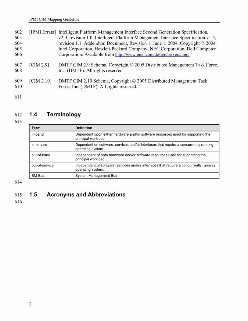
[IPMI Errata] Intelligent Platform Management Interface Second Generation Specification, 602 v2.0, revision 1.0, Intelligent Platform Management Interface Specification v1.5, 603 revision 1.1, Addendum Document, Revision 1, June 1, 2004. Copyright © 2004 604 Intel Corporation, Hewlett-Packard Company, NEC Corporation, Dell Computer 605 Corporation. Available from http://www.intel.com/design/servers/ipmi 606
[CIM 2.9] DMTF CIM 2.9 Schema, Copyright © 2005 Distributed Management Task Force, 607 Inc. (DMTF). All rights reserved. 608
[CIM 2.10] DMTF CIM 2.10 Schema, Copyright © 2005 Distributed Management Task 609 Force, Inc. (DMTF). All rights reserved. 610
611
1.4 Terminology 612 613
Term Definition
in-band Dependent upon either hardware and/or software resources used for supporting the principal workload.
in-service Dependent on software, services and/or interfaces that require a concurrently running operating system.
out-of-band Independent of both hardware and/or software resources used for supporting the principal workload.
out-of-service Independent of software, services and/or interfaces that require a concurrently running operating system.
SM-Bus System Management Bus
614
1.5 Acronyms and Abbreviations 615 616
IPMI CIM Mapping Guideline
3
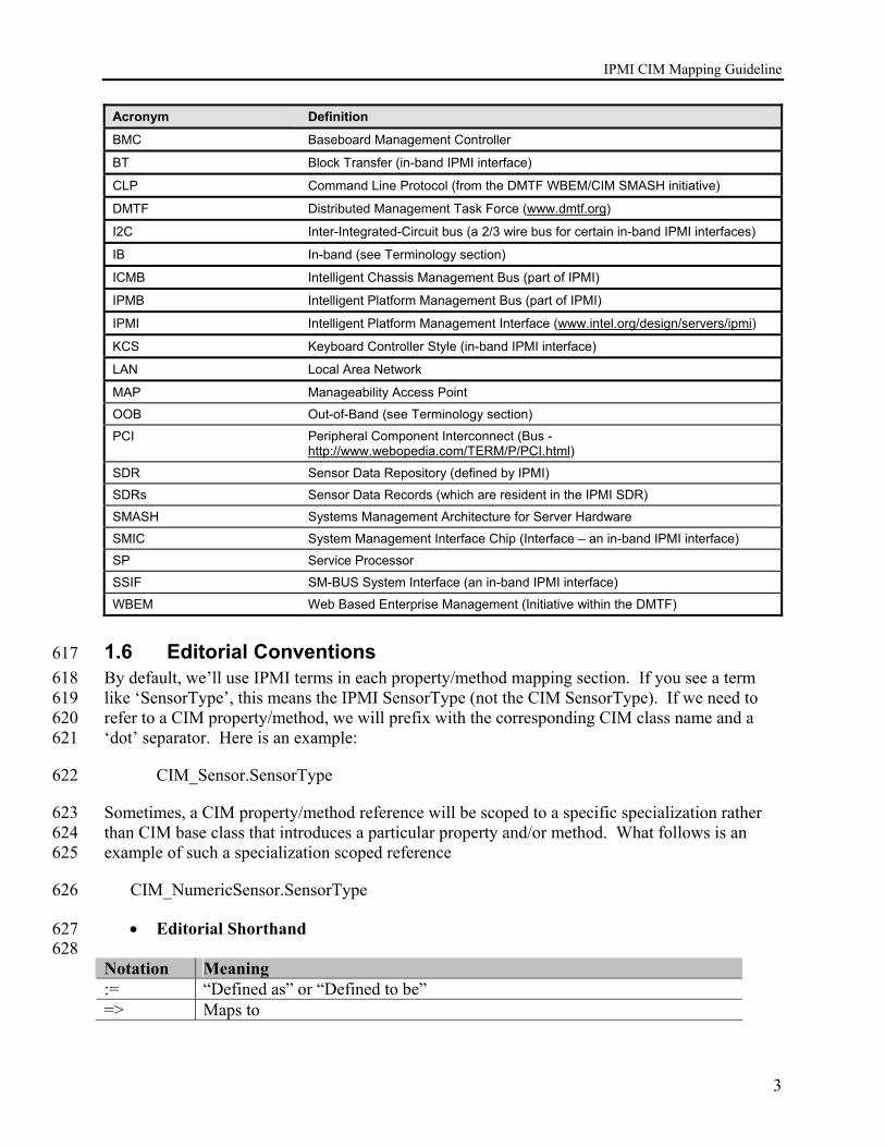
Acronym Definition
BMC Baseboard Management Controller
BT Block Transfer (in-band IPMI interface)
CLP Command Line Protocol (from the DMTF WBEM/CIM SMASH initiative)
DMTF Distributed Management Task Force (www.dmtf.org)
I2C Inter-Integrated-Circuit bus (a 2/3 wire bus for certain in-band IPMI interfaces)
IB In-band (see Terminology section)
ICMB Intelligent Chassis Management Bus (part of IPMI)
IPMB Intelligent Platform Management Bus (part of IPMI)
IPMI Intelligent Platform Management Interface (www.intel.org/design/servers/ipmi)
KCS Keyboard Controller Style (in-band IPMI interface)
LAN Local Area Network
MAP Manageability Access Point
OOB Out-of-Band (see Terminology section)
PCI Peripheral Component Interconnect (Bus - http://www.webopedia.com/TERM/P/PCI.html)
SDR Sensor Data Repository (defined by IPMI)
SDRs Sensor Data Records (which are resident in the IPMI SDR)
SMASH Systems Management Architecture for Server Hardware
SMIC System Management Interface Chip (Interface – an in-band IPMI interface)
SP Service Processor
SSIF SM-BUS System Interface (an in-band IPMI interface)
WBEM Web Based Enterprise Management (Initiative within the DMTF)
1.6 Editorial Conventions 617 By default, we’ll use IPMI terms in each property/method mapping section. If you see a term 618 like ‘SensorType’, this means the IPMI SensorType (not the CIM SensorType). If we need to 619 refer to a CIM property/method, we will prefix with the corresponding CIM class name and a 620 ‘dot’ separator. Here is an example: 621
CIM_Sensor.SensorType 622
Sometimes, a CIM property/method reference will be scoped to a specific specialization rather 623 than CIM base class that introduces a particular property and/or method. What follows is an 624 example of such a specialization scoped reference 625
CIM_NumericSensor.SensorType 626
• Editorial Shorthand 627 628
Notation Meaning := “Defined as” or “Defined to be” => Maps to

IPMI CIM Mapping Guideline
4
1.7 Notational Conventions 629
• Operators 630 631 Operator Example Description <> <SDR Type 1 bytes 49+>
<CIM_Sensor.Name> These brackets are a substitution macro. The <…> bracket enclosed text references something whose corresponding value should be substituted. For example, Table 37-1 in the IPMI v1.5 specification describes bytes 49+ in the Type 1 IPMI Sensor Data Record (SDR) as being the sensor’s ID string bytes. Reuse and the Define Once Discipline: The <CIM_Sensor.Name> example references the elsewhere defined mapping for the CIM_Sensor class’s Name property. In the <CIM_Sensor.Name> example, the previously defined mapping is being referenced and re-used (rather than defined in more than one place). We especially encourage such reuse when references cross documents and/or chapter divisions.
(<type>) (Boolean) (String)
Cast/convert to the given fundamental type. For example, a binary value [0,1] might be casted/converted to a CIM boolean value [“true”,”false”]. We often use the cast operator to emphasize the types of the values involved. These redundant/unnecessary casts (of say a string value to a string value) are simply of way of making the mapping specification more self-documenting.
EStr() EStr(SensorType) Maps a value to an associated description string. This is the “explain” string macro/function. It amounts to mapping an enumeration’s value to an associated enumeration’s symbolic value. This also covers any other similar sort of associative array based mapping-to-string. For example, IPMI v1.5 Sensor Type (hex defined) numeric value is defined in Table 36-3. Each value is associated in Table 36-3 with a corresponding description string.
TruncAt( <integer>, string)
TruncAt(5, ”Hereisabigstring”) == “Herei”
Truncates a sequence at a specified number of entries. Often used to truncate a string (a sequence of characters) to a given length. If the string is shorter than the given length, TruncAt indicates no change to the input string (i.e. a no-op).
Relops (=,>,<,etc.) LogicalOps (&&, ||)
SensorType=02h Relational operators represent filtering/scoping predicates. For example, SensorType=[01h-04h] means SensorType values limited to the range 01h to 04h. Notice that this mixes the equivalence operator and a regular expression. The same example could be denoted as follows: SensorType>=01h && SensorType<=04h Or SensorType>00h && SensorType<05h

IPMI CIM Mapping Guideline
5
|| “foo” || “bar” => “foobar”
String concatenation. The ‘||’ operator is a logical ‘OR’ if it’s operands are relational expressions. It is string concatentation otherwise (and it requires string type operand context to function as string concatenation).
632 633
• Regular expressions 634 Some common regular expression syntax may be intermingled in the mapping 635 definitions. 636
If we eventually need both a rigorously defined and an advanced regular expression 637 syntax, our direction is to conform the Python “re” module regular expression syntax 638 (see Programming Python, 2nd Edition, Lutz, Mark, O’Reilly & Associates, Inc, 639 Sebastopol, California, 2001, ISBN 0-596-00085, p1041+). The Python regular 640 expression syntax deliberately subsumes the Perl regular expression syntax. 641
• Python style pseudo-code (when and if necessary) 642 Since Python was designed to be a C/C++ style pseudo-code, we’ll adopt the Python 643 language conventions for any procedural mapping specifications. We do not intend to 644 write executable Python code. We do not imply anything about Python nor Python’s 645 suitability for any given purpose. Our interest in Python is only as a means to express 646 any necessary IPMI-to-CIM procedural mapping logic (fragments). We adopt Python’s 647 widely familiar, C/C++ style, syntax . This is just an expedient choice of procedural 648 specification languages. 649
650
When, and if, we need to resort to procedural mapping specifications, we’ll introduce 651 the corresponding Python fragments with a “Procedure” heading. The Python-like 652 pseudo-code will indulge in some non-Python notation where the possibility for 653 confusion is low and where the notation reinforces connections to either IPMI 654 terminology/notation and/or CIM terminology/notation. For example, IPMI constant 655 notation like “03h” might be used rather than Python’s “0x3”. We also use compact 656 self-assignment forms from C/C++ (like ||= for concentration assignment). This is just 657 more concise and often more convenient. 658
• In-line comments 659
In-line (pseudo-code) comment syntax follows the Python conventions. 660
# This is a comment until end of current line. Multi-line comments 661
# much use a ‘#’ character to introduce each comment line. 662
1.8 Referenced Standards 663
Standard/Specification Version Source Citation CIM Infrastructure Specification
2.3 DMTF DSP 0004, www.dmtf.org/standards/cim
CIM Schema 2.10 DMTF www.dmtf.org/standards/cim
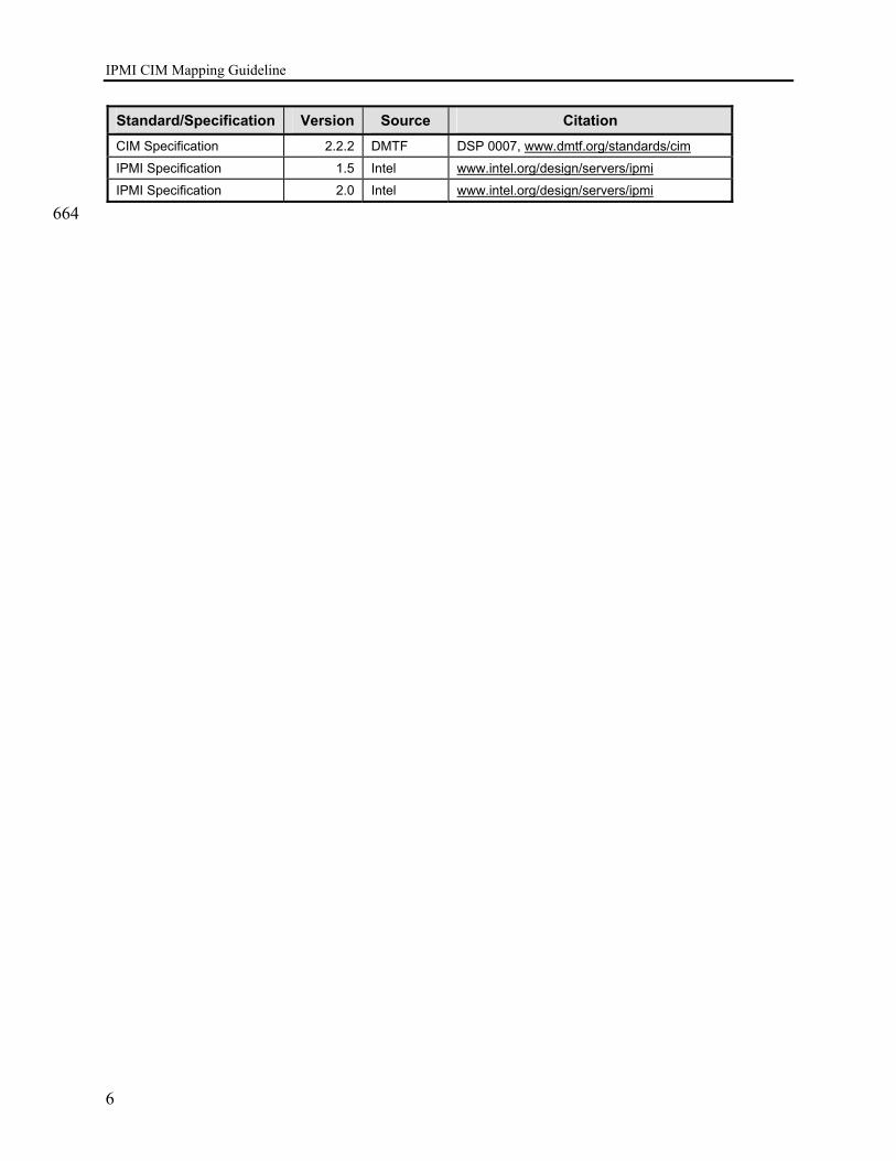
IPMI CIM Mapping Guideline
6
Standard/Specification Version Source Citation CIM Specification 2.2.2 DMTF DSP 0007, www.dmtf.org/standards/cim
IPMI Specification 1.5 Intel www.intel.org/design/servers/ipmi
IPMI Specification 2.0 Intel www.intel.org/design/servers/ipmi
664

IPMI CIM Mapping Guideline
7
2 Common Steps for Mapping Process 665 This section presents the general process that instrumentation provider software would use for 666 accessing an IPMI-based platform management subsystem, discovering its available 667 management capabilities, and mapping those capabilities to CIM objects described in this 668 document. These steps are presented as a guide to software design and to applying the IPMI 669 specifications. These steps are summarized as follows: 670
1. Discover and connect to the IPMI interface for the particular managed system. 671
2. Discover and enumerate the IPMI Entities, Sensors, and FRU information creating a 672 logical ‘list’ of IPMI capabilities. 673
3. Take this logical listing and use it to instantiate and populate CIM objects and 674 associations according to the discovered capabilities on the given system. 675
2.1 Discovering IPMI Interfaces 676 Instrumentation that maps from IPMI to CIM must first discover and connect to the IPMI 677 platform management subsystem via one of the IPMI interfaces. The IPMI interfaces may be 678 classified into three types: System, Remote, and Internal. 679
2.1.1 System Interfaces 680 The System Interface is a set of registers that software running on the managed system uses to 681 directly access the IPMI subsystem. There are three types of system interface defined in [IPMI 682 1.5]: the KCS (keyboard controller style) interface, the BT (block transfer) interface, and the 683 SMIC (server management interface chip) interface. Of these, the KCS interface is by far the 684 most widely deployed, followed by the BT interface. The SMIC interface is an older interface 685 that is not recommended for new designs. [IPMI 2.0] introduced a fourth system interface, called 686 SSIF (SMBus System Interface) that is used with low cost IPMI BMCs (baseboard management 687 controllers). 688
Local instrumentation software must decide which types of System Interface it will support. It is 689 highly recommended that the KCS interface be supported. Other interfaces should be considered 690 based on the target systems for the software. The IPMI Web Site, 691 http://www.intel.com/design/servers/ipmi, has reference drivers and sample code that can assist 692 with the development of software for a number of the system interfaces. 693
Section 6 of the IPMI specifications describes the System Interfaces and their operation. In this 694 section, there is a subsection titled “System Interface Discovery and Multiple Interfaces”. This 695 subsection describes the steps that software should use to discover the type of system interface 696 used on a given platform, its location, and how to handle the situation if multiple system 697 interfaces are present. 698
2.1.2 Remote Interfaces 699 The IPMI platform management subsystem on a given system may also be accessible remotely 700 via IPMI remote interfaces. The remote interfaces include serial/modem and LAN (Ethernet). 701

IPMI CIM Mapping Guideline
8
The IPMI remote interfaces incorporate their own media-specific protocols for delivering IPMI 702 messages to the platform management subsystem. However, the IPMI messages themselves are 703 the same regardless of the interface over which they’re delivered. Thus, in general, the same 704 IPMI management capabilities that can be accessed locally can also be accessed via the remote 705 interfaces3. This means that the same general process of mapping IPMI capabilities to CIM 706 locally (via the system interface) can also be used for mapping IPMI to CIM via the remote 707 interfaces. This enables the possibility of creating ‘proxy’ software to provide a CIM-based 708 interface to remote IPMI-based systems. 709
Because the interfaces provide remote access, the serial/modem and LAN interfaces incorporate 710 options for securing the interfaces and restricting access to specific users that are have been 711 configured and enabled for IPMI access to a particular BMC. Thus, a remote application must 712 not only support the protocol requirements for deliver IPMI messages over the interface, but also 713 include support for ‘logging in’ to the remote system as a user that has the necessary privilege 714 level to support IPMI-to-CIM mapping. 715
Unless otherwise indicated, the full set of capabilities enabled by IPMI-to-CIM mapping can be 716 accomplished by a user that has “Operator” privilege. Refer to Appendix G in the IPMI 717 specifications for a listing of the privilege levels for the IPMI commands. 718
IPMI over Serial/Modem has several different access protocols that can be used. These are 719 referred to as “Basic Mode”, “Terminal Mode”, and “PPP Mode”. Basic Mode support is 720 mandatory for IPMI over Serial/Modem, the other modes are optional. An application can 721 therefore rely on Basic Mode as being common across platforms that support IPMI over 722 Serial/Modem. 723
The approach to handling user logins varies between the serial access protocols. However, all 724 authenticated interfaces share the same association of user names and privilege levels. The PPP 725 interface also incorporates the option for an additional layer of “link” security where the serial 726 communication connection itself must first be authenticated, and then IPMI users are 727 authenticated on top of that. An application that supports IPMI over PPP should also support the 728 options for link-level security. 729
IPMI over LAN includes support for enabling applications to discover IPMI-based systems on 730 the network. The serial/modem interfaces presume that the application has a-priori knowledge of 731 the phone number necessary to connect to the managed system, or that there is a direct 732 connection available between the managing (console) system and the IPMI serial interface. 733 However, once the serial connection is established, the interfaces include mechanisms that allow 734 the availability of IPMI to be confirmed. 735
It should be noted that the serial interfaces may also be used with a capability called “Serial Port 736 Sharing” where access to the system’s serial controller can be shared with IPMI access. This 737 guideline does not cover CIM-based instrumentation access to the system serial connection via 738 IPMI Serial Port Sharing. A remote application should be aware, however, that it will need to 739 take additional steps to switch the serial connection to the BMC if Serial Port Sharing is in effect. 740
3 Typically, only certain interface-specific IPMI commands will not be available on other interfaces. For example,
commands related to LAN discovery and session setup are not available over other interfaces.
IPMI CIM Mapping Guideline
9
2.2 Internal Interfaces 741 IPMI also defines interfaces that can be used to enable other management controllers, add-in 742 cards, and other devices to access IPMI ‘inside the box’. These internal interfaces include the 743 IPMB (Intelligent Platform Management Bus), the PCI SMBus, and an inter-chassis bus referred 744 to as the ICMB4 (Intelligent Chassis Management Bus). (While the ICMB bus extends between 745 chassis, it is more characteristic of an internal interface because it is considered to be a 746 ‘physically secure’ and therefore does not include ‘user logins’ for controlling user access. 747
As with the remote interfaces, the same IPMI management capabilities that can be accessed via 748 the System Interface can also be accessed via the internal interfaces. This means that the same 749 general process of mapping IPMI capabilities to CIM can be used, creating the possibility of an 750 add-in card that incorporates the IPMI-to-CIM mapping to provide a CIM-based remote interface 751 for the managed system. 752
2.3 Discovery and Enumeration of IPMI Entity, Sensor, and FRU 753 Information and Associations 754
Once software is able to access IPMI, the next major step of the mapping process is for software 755 to discover and enumerate the particular platform’s IPMI capabilities so they can be mapped into 756 CIM. This includes discovering the control capabilities, sensors, FRU (field replaceable unit) 757 information, and the associations between sensors and FRU information for the entities that are 758 monitored and managed through IPMI. 759
This discovery and enumeration process can be thought of as creating a logical ‘list’ of the IPMI 760 capabilities for a given platform. Once this logical listing is created, it can be used to drive the 761 instantiation of CIM objects for accessing those capabilities. 762
2.3.1 Recommendations on the access and use of SDR Info 763 The IPMI Sensor Data Records (SDRs) are a key element to the enumeration and discovery of 764 IPMI sensors, FRU information, and the entities they are associated with. In most cases, it will 765 be faster and more efficient for software to read out the entire set of sensor data records in bulk 766 into a local file or system RAM and work with the copy of the SDRs rather than to access SDRs 767 and process them one at a time. 768
In addition, if an application is responsible for monitoring multiple systems, it is useful to cache 769 information about the managed systems rather than accessing it anew each time the managed 770 system is accessed. IPMI provides timestamps on the SDR Repository (accessed using the Get 771 SEL Info command) that software can use to tell if the SDR contents have changed since the last 772 time the info was accessed. 773
4 There is a separate document that describes the ICMB and its operation. Refer to the reference to [ICMB] in the
IPMI specifications.

IPMI CIM Mapping Guideline
10
2.4 Entity Discovery 774 IPMI supports a type of SDR called “Entity Association Records”. These records allow physical 775 or logical Entities to grouped together under a common ‘container’ Entity. The container Entity 776 may itself be a ‘contained’ Entity in another Entity Association. Thus, Entity Associations can 777 form a ‘tree’ hierarchy expressing relationships between Entities and/or groups of Entities. 778
There can be an interdependency between IPMI Sensors and Entities. If the container Entity at 779 the top of a given Entity Association or Entity Association Hierarchy is absent (as indicated by a 780 Presence sensor or by presence bit associated with a sensor for the Entity) then all ‘contained’ 781 Entities under that hierarchy are considered to be absent. Consequently, any Sensors associated 782 with those contained Entities are also considered absent. 783
Because multiple sensors can be associated with a single Entity, and because the presence of 784 multiple Entities can be determined by a the presence of an Entity Association or Entity 785 Association Hierarchy, it is generally more efficient to determine the presence of Entities first, 786 then Sensors. 787
Whether an Entity Association is ‘present’, or ‘absent’ is based on whether the container Entity 788 for the Association has sensors associated with it, and if so, what the state of those sensors is, as 789 follows: 790
• If the container Entity does not have any sensors associated with it, then the association 791 is assumed to be ‘present’. 792
• If the container Entity has one or more sensors associated with it, but all sensors are 793 ‘scanning disabled’ or are inaccessible, then the association should be considered 794 ‘absent’ and should be ignored. I.e. software should act as if that association was not 795 even listed in the SDRs. 796
• If the container Entity has one or more ‘scanning enabled’ associated with it, and none 797 of those sensors are a presence sensor or presence bit that indicates that the container 798 Entity is absent, then the association is assumed to be ‘present’ (valid). 799
• If the container Entity has a presence sensor or bit associated with it that indicates the 800 container Entity is absent, then the overall association is said to be ‘explicitly absent’ 801 and the container Entity and any contained Entities and lower level associations should 802 not be instantiated because of being listed under that association. (Note that the same 803 Entities may still become instantiated because they’re listed under a different Entity 804 association or association hierarchy that is present.) 805
2.4.1 Entity presence rules 806 The following is an brief overview of the different ways Entity presence can be determined in 807 IPMI. This is described in more detail in 10.3.2 Entity Instantiation Algorithm. In this section, 808 the words “the Entity” shall be used as a shorthand for “The particular instance and type of 809 Entity”. 810

IPMI CIM Mapping Guideline
11
2.4.1.1 Explicit by Entity Association 811 The Entity listed under an “Entity Association” that is defined by one or more Entity Association 812 Records and is present 813
AND 814
None of the Entity Associations that are higher up in the Entity hierarchy are explicitly absent. 815
AND 816
The Entity is not listed in the Entity ID/Entity Instance fields of the SDR for a Presence sensor, 817 nor a sensor that includes a presence bit that indicates the Entity is ‘not present’ or ‘not installed’ 818 (see note below). 819
2.4.1.2 Explicit by Sensor SDR or Event SDR 820 The Entity is not listed under any present or explicitly absent Entity Association Hierarchy, but is 821 listed in the Entity ID/Entity Instance fields of one or more “sensor” or “event only” SDRs 822 (Type 01h, 02h, or 03h). 823
AND 824
The Entity is not listed in the Entity ID/Entity Instance fields of the SDR for a Presence sensor, 825 nor a sensor that includes a presence bit that indicates the Entity is ‘not present’ or ‘not 826 installed’(see note below). 827
AND 828
At least one sensor associated with then Entity is enabled (See 2.5, Sensor Discovery, for the 829 definition of an ‘enabled’ sensor). 830
2.4.1.3 Explicit by FRU Device Locator Record 831 The Entity is not listed under any Entity Association Hierarchy (regardless of whether the 832 hierarchy is present or absent), but is listed in the Entity ID/Entity Instance fields of one or more 833 FRU Device Locator SDRs (Type 11h). 834
AND 835
There are no sensors associated with the Entity, or at least one sensor associated with then Entity 836 is enabled (See 2.5, Sensor Discovery, for the definition of an ‘enabled’ sensor). 837
AND 838
The Entity is not listed in the Entity ID/Entity Instance fields of the SDR for a Presence sensor, 839 nor a sensor that includes a presence bit that indicates the Entity is ‘not present’ or ‘not installed’ 840 (see note below). 841
AND 842

IPMI CIM Mapping Guideline
12
The FRU Device for associated with the Entity is accessible by software. 843
2.4.1.4 Implicit by Sensor Type 844 The existence of an Entity can also be inferred by the Sensor Type. For example, if a Fan sensor 845 is present, then it implies the existence of a Fan. This is done only when the Sensor Type and the 846 Entity ID do not match, and only for certain Sensor Types, listed in a table in Section 10.3.1, 847 Mapping Entity ID’s to CIM Classes. An Entity that has its presence inferred this way is not 848 explicitly identified by IPMI Entity ID/Entity Instance numbers. Therefore, for instance 849 identification purposes, some unique ID must be synthesized. In this specification, a combination 850 of the Sensor Number, Owner ID, and other information, is used to synthesize a CIM 851 Sensor.DeviceID value that is used as the instance identifier.(see note below). Thus, Entity can 852 be inferred to exist if: 853
The Entity the is explicitly associated with the sensor (the Entity identified by the Entity ID and 854 Entity Instance fields in the SDR) is present by one of the two preceding explicit presence 855 mechanisms. 856
AND 857
The Sensor Type in the Sensor Data Record is of a type that implies the existence of a physical 858 Entity, per Table 16 “Physical” Sensor Types to Entity Mapping . 859
AND 860
The Entity ID implied by the Sensor Type in the Sensor Data Record for the sensor does not 861 match the explicit type given by the Entity ID in the Sensor Data Record. 862
AND 863
At least one sensor associated with then Entity is enabled (See 2.5, Sensor Discovery, for the 864 definition of an ‘enabled’ sensor). 865
2.4.1.5 Implicit by FRU Data 866 The existence of an Entity can also be inferred by IPMI FRU data. For example, if there is 867 Chassis information in a FRU Device, it implies the existence of a physical chassis. This 868 mechanism is used when there is not a FRU Device Locator record for the FRU Device that calls 869 out a particular Entity ID and Entity Instance for an Entity to be associated with the FRU data. 870 As with Entities whose existence is “Implicit by Sensor Type” it is necessary to synthesize an 871 instance identifier in lieu of having explicit Entity ID and Entity Instance information. 872
FRU Information Type: 873
• Chassis Info Area, implies existence of a Chassis Entity. 874
• Board Info Area, implies existence of a board or module. 875 876
IPMI CIM Mapping Guideline
13
Refer to the steps outlined in Section 10, IPMI Entity Mapping, and Table 16 “Physical” 877 Sensor Types to Entity Mapping. 878
Note: 879
The two presence mechanisms (Presence sensor or presence bit) should not be used 880 simultaneously in an implementation. However, if an implementation does utilize both 881 mechanisms with a given Entity, the following interpretation rule applies 882
• the Entity should be considered to be 'not present' (absent) if either mechanism reports 883 'not present'. 884
• the Entity should be considered to be 'present' if both mechanisms report present 885
• if scanning is disabled for the sensor for either explicit mechanism, the remaining 886 mechanism is utilized as if the other didn't exist. 887
• if scanning is disabled for both mechanisms, the rules for the Entity Presence Sensor 888 apply - meaning that ALL sensors associated with that Entity should be ignored. 889
890
Refer to the IPMI Specifications to find out which sensor types include sensor-specific offset bits 891 that serve as presence bits for associated Entities. 892
2.5 Sensor Discovery 893 This step consists of the discovery of ‘enabled’ sensors or ‘event only’ sensors where the Entity 894 associated with the sensor is part of an Entity Association or Entity Association Hierarchy that is 895 present, or the Entity is not covered by an Entity Association or Entity Association Hierarchy. 896
An ‘enabled’ sensor is a sensor that responds to a Get Sensor Reading, Get Sensor Event Enable, 897 or Get Sensor Event Status that returns bit [6] as 1b, indicating ‘sensor scanning enabled’. An 898 ‘event only’ sensor is a sensor that is listed using the ‘type 03h’ Event Only SDR. 899
The Entity that is associated with a sensor is identified by the Entity ID and Entity Instance fields 900 in the SDR for the sensor. 901
If a sensor is not listed in the SDRs it should be ignored. I.e. should be considered ‘non-existent’ 902 with respect to this Sensor Discovery step. 903
2.5.1 Sensor Presence Rules 904 Thus, as sensor should be considered to be present (and a candidate for CIM instantiaton) if: 905 906
The sensor is listed in the SDRs 907 AND 908 The sensor is ‘scanning enabled’ 909 AND 910
IPMI CIM Mapping Guideline
14
The Entity associated with the sensor is not part of an Entity Association or Entity 911 Association Hierachy 912 913
OR 914 915 The sensor is listed in the SDRs 916 AND 917 The sensor is ‘scanning enabled’ 918 AND 919 The Entity associated with the sensor is part of an Entity Association or Entity 920 Association Hierarchy that is present (refer to 2.4.1, Entity presence rules, above). 921
2.6 FRU Device Discovery 922 IPMI FRU Devices hold FRU (Field Replaceable Unit) information for different replaceable 923 Entities in the system. This can include information such as serial number, model, manufacturer, 924 part number, etc. FRU Devices are accessed by software either as ‘logical’ or ‘physical’ FRU 925 Devices. Logical FRU Devices are accessed by sending Read- and Write FRU Data IPMI 926 command to the management controller that provides access to the device. 927
Physical FRU Devices (also referred to as ‘non-intelligent’ FRU Devices) are accessed as 928 separate SEEPROM (Serial Electrically Erasable Programmable Read-Only Memory) devices on 929 a physical I2C or SMBus segment. Thus, physical FRU devices are often used provide FRU 930 information on add-in cards, since only a simple SEEPROM is required to provide the 931 information, rather than a management controller that can handle IPMI commands. To access 932 physical FRU devices, software uses the IPMI Master Write-Read command to generate 933 SEEPROM access transactions on the target I2C or SMBus behind a management controller. 934
Logical and Physical FRU Device access is described in more detail in the IPMI Specification. In 935 particular, refer to the chapter 38, Accessing FRU Devices, and the documentation on the Read- 936 and the Master Write-Read command. 937
FRU Devices are discovered by the following mechanisms: 938
2.6.1 By BMC Primary FRU Device 939 Since IPMI requires a BMC to be present, the BMC is not required to have a Management 940 Controller Device Locator record in the Sensor Data Records. The BMC has a “Primary FRU 941 Device” which is accessed as logical FRU Device 0 on LUN 00b of the BMC using the Read- 942 and Write FRU Data IPMI commands. 943
2.6.2 By Management Controller Device Locator Record 944 Management Controllers other than the BMC are listed using individual Management Controller 945 Device Locator (Type records in the Sensor Data Records. A “Device Capabilities” field in the 946 record includes a bit that indicates whether or not the management controller supports a “Primary 947 FRU Inventory Device”. I.e. has FRU information that is accessible as logical FRU Device 0 on 948 LUN 00b of the management controller using the Read- and Write FRU Data IPMI commands. 949
IPMI CIM Mapping Guideline
15
2.6.3 By FRU Device Locator Record 950 FRU Devices that are not Primary FRU Devices are listed using individual FRU Device Locator 951 records in the Sensor Data Records. The record provides information on whether the device is 952 accessed as a Physical or Logical FRU Device.\ 953
2.7 Discovering Sensor, Entity, & FRU Associations 954 The following figures graphically represent some common inter-relationships between sensors 955 and Entities and how they relate to sensor and entity presence. In general, software uses the 956 following information sources to determine and generate CIM associations between sensors, 957 Entities, and FRU information: 958
• Entity ID Information in sensor SDRs: Each sensor is associated with a single Entity, 959 and there can be a multiple sensors associated with a given Entity. Software uses the 960 Entity ID and Entity Instance information to identify the Entity that the sensor is 961 associated with. 962
• Entity Association records: Entities can be associated with one another in a 963 container/contained relationship via Entity Association records. Entity Association 964 Records can be nested to form an “Entity Association Hierarchy”. 965
• FRU- and Management Controller Device Locator records: FRU Information is 966 associated to Entities and management controllers via the Entity ID and Entity Instance 967 fields in FRU Device Locator records and Management Controller Device Locator 968 records. 969
• BMC Primary FRU Device information: When an Management Controller Device 970 locator record is not present (as is typical for the BMC) the FRU information in the 971 Primary FRU Device is assumed to be associated with the FRU that the BMC itself is 972 associated with. For example, if there’s board information in the BMC Primary FRU, it 973 is assumed that the information is for the board that the BMC is mounted on. 974
975
• Chassis Info Area is FRU data associated with the overall chassis for the system. 976 There should be only one set of Chassis Info Area data in the IPMI subsystem. 977
• Board Info Area, implies existence of a board or module or other FRU. The name 978 ‘Board Info Area’ is somewhat a misnomer, because the usage is not restricted to 979 just circuit boards. This area is also typically used to provide FRU information for 980 any replaceable entities, boards, andor sub-assemblies that are not sold as 981 standalone products separately from other components. For example, individual 982 boards from a board set, or a sub-chassis or backplane that’s part of a larger 983 chassis. If an explicit Entity ID and Entity Instance is not associated with the FRU 984 Device, it is assumed that the information is for the main system board. 985
• Product Info Area, if not associated with an explicit Entity via an Entity ID and 986 Entity Instance, is assumed to be for the overall product. I.e. associated with the 987 computer system. 988
989
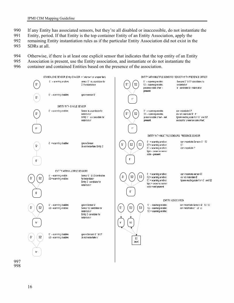
IPMI CIM Mapping Guideline
16
If any Entity has associated sensors, but they’re all disabled or inaccessible, do not instantiate the 990 Entity, period. If that Entity is the top container Entity of an Entity Association, apply the 991 remaining Entity instantiation rules as if the particular Entity Association did not exist in the 992 SDRs at all. 993
Otherwise, if there is at least one explicit sensor that indicates that the top entity of an Entity 994 Association is present, use the Entity association, and instantiate or do not instantiate the 995 container and contained Entities based on the presence of the association. 996
997 998
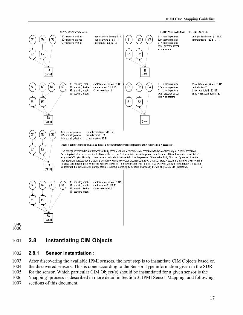
IPMI CIM Mapping Guideline
17
999 1000
2.8 Instantiating CIM Objects 1001
2.8.1 Sensor Instantiation : 1002 After discovering the available IPMI sensors, the next step is to instantiate CIM Objects based on 1003 the discovered sensors. This is done according to the Sensor Type information given in the SDR 1004 for the sensor. Which particular CIM Object(s) should be instantiated for a given sensor is the 1005 ‘mapping’ process is described in more detail in Section 3, IPMI Sensor Mapping, and following 1006 sections of this document. 1007

IPMI CIM Mapping Guideline
18
2.8.1.1 Sensor state/reading rules 1008 When populating attributes in CIM Objects that return state or reading information from a 1009 sensor, it is necessary to know when the IPMI sensor is returning valid information. This can 1010 generally be determined according to the following rules. 1011
4. ignore sensor state/reading if the reading/state unavailable bit for the sensor is set. 1012
5. if the sensor includes a 'presence' bit, ignore reading/state information for the sensor 1013 that requires the associated Entity to be present. 1014
6. if a sensor that includes a 'presence' bit is associated with the container Entity of an 1015 Entity-Association AND the sensor state = "not present", ignore the reading/state 1016 information for the sensor that requires the associated Entity to be present, and ignore 1017 the reading/state of any sensors for contained Entities in the Entity association. 1018
7. if an Entity Presence sensor is associated with the container Entity of an entity-1019 association AND the sensor state = "not present", ignore the reading/state of any 1020 contained sensors in the Entity association. 1021
Note: 1022
Because IPMI specifies that disabled sensors (sensors that are set to ‘sensor scanning disabled’) 1023 should be ignored by software, it is recommended that instrumentation provider software does 1024 not disable sensors once they’ve been instantiated, since if the software was terminated, the 1025 sensors would remain disabled and a subsequent load of the software would ignore them. 1026
Instrumentation software should not assume that the initial disabled state of a sensor (e.g. 1027 scanning enabled or disabled) will remain the same across restarts of the operating system, since 1028 it’s possible that a hardware change could have occurred between OS restarts that would cause 1029 the management controller to disable a sensor that had been previously enabled. 1030
Refer to Section 3.4.1.2, Method: RequestStateChange for additional information. 1031
2.8.2 Entity Instantiation 1032 Once the IPMI Entities have been discovered, a CIM Objects should be instantiated according to 1033 the Entity ID for the Entity according to the steps described in Section 10, IPMI Entity Mapping. 1034 In addition to instantiating CIM Objects based on the Entities, CIM associations are created that 1035 relate those objects to one another, and to a ComputerSystemPackage association under the host 1036 Computer System. 1037
2.8.3 FRU instantiation 1038 IPMI FRU information is used as part of the Entity Instantiation process described in Section 10, 1039 IPMI Entity Mapping. In general, the instrumentation provider software should apply discovered 1040 FRU information as follows: 1041
• Instantiate any FRU information associated with an instantiated Entity. 1042

IPMI CIM Mapping Guideline
19
• Instantiate any FRU information associated with the BMC and any present satellite 1043 management controllers. 1044
• Instantiate any FRU information for FRU devices listed in the SDRs and associated with an 1045 Entity that is otherwise unreferenced in the SDRs. 1046
• It is possible that FRU information could be available for an Entity that is instantiated but 1047 not present (this is because FRU information can be kept in separate devices from the 1048 Entity). Software should check for this possibility and should assume that if the Entity is not 1049 present, FRU Information for the Entity is not valid and should be ignored. 1050
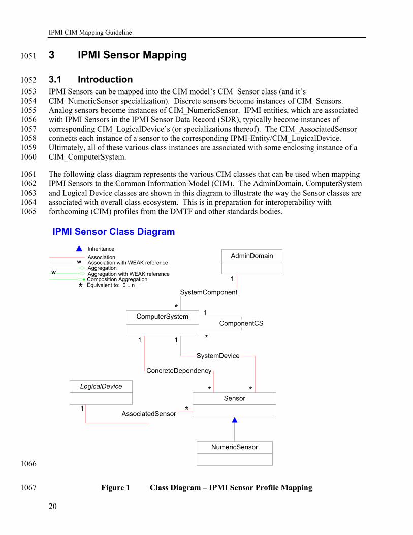
IPMI CIM Mapping Guideline
20
3 IPMI Sensor Mapping 1051
3.1 Introduction 1052 IPMI Sensors can be mapped into the CIM model’s CIM_Sensor class (and it’s 1053 CIM_NumericSensor specialization). Discrete sensors become instances of CIM_Sensors. 1054 Analog sensors become instances of CIM_NumericSensor. IPMI entities, which are associated 1055 with IPMI Sensors in the IPMI Sensor Data Record (SDR), typically become instances of 1056 corresponding CIM_LogicalDevice’s (or specializations thereof). The CIM_AssociatedSensor 1057 connects each instance of a sensor to the corresponding IPMI-Entity/CIM_LogicalDevice. 1058 Ultimately, all of these various class instances are associated with some enclosing instance of a 1059 CIM_ComputerSystem. 1060
The following class diagram represents the various CIM classes that can be used when mapping 1061 IPMI Sensors to the Common Information Model (CIM). The AdminDomain, ComputerSystem 1062 and Logical Device classes are shown in this diagram to illustrate the way the Sensor classes are 1063 associated with overall class ecosystem. This is in preparation for interoperability with 1064 forthcoming (CIM) profiles from the DMTF and other standards bodies. 1065
IPMI Sensor Class Diagram
Association
AggregationAssociation with WEAK reference
Inheritance
Aggregation with WEAK reference
w
w
* Equivalent to: 0 .. nComposition Aggregation
ComputerSystem
AdminDomain
ComponentCS
NumericSensor
ConcreteDependency
LogicalDevice
Sensor
SystemDevice
SystemComponent
AssociatedSensor
1
1
1
1
1 *
* *
*
*
1066
Figure 1 Class Diagram – IPMI Sensor Profile Mapping 1067
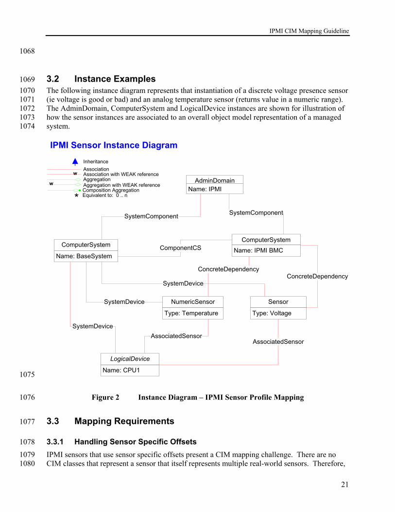
IPMI CIM Mapping Guideline
21
1068
3.2 Instance Examples 1069 The following instance diagram represents that instantiation of a discrete voltage presence sensor 1070 (ie voltage is good or bad) and an analog temperature sensor (returns value in a numeric range). 1071 The AdminDomain, ComputerSystem and LogicalDevice instances are shown for illustration of 1072 how the sensor instances are associated to an overall object model representation of a managed 1073 system. 1074
IPMI Sensor Instance Diagram
Name: BaseSystem
ComputerSystem
Association
AggregationAssociation with WEAK reference
Inheritance
Aggregation with WEAK reference
w
w
* Equivalent to: 0 .. nComposition Aggregation
ComputerSystem
Name: IPMI BMC
Name: IPMIAdminDomain
SystemComponent
ComponentCS
NumericSensor
Type: Temperature
SystemDevice
Name: CPU1
LogicalDevice
Sensor
Type: Voltage
SystemDevice
AssociatedSensor
SystemComponent
AssociatedSensorSystemDevice
ConcreteDependencyConcreteDependency
1075
Figure 2 Instance Diagram – IPMI Sensor Profile Mapping 1076
3.3 Mapping Requirements 1077
3.3.1 Handling Sensor Specific Offsets 1078 IPMI sensors that use sensor specific offsets present a CIM mapping challenge. There are no 1079 CIM classes that represent a sensor that itself represents multiple real-world sensors. Therefore, 1080

IPMI CIM Mapping Guideline
22
mapping IPMI sensors with Sensor-specific Offsets must involve the generation an instance of 1081 CIM_Sensor that asserts each Sensor-specific offset. Technically, this is necessary only for 1082 those Sensor-specific Offsets which are enabled. The IPMI SDR Readable Mask, Assert Mask, 1083 or Deassert Mask describe just which Sensor-specific Offsets are enabled. 1084
Instances of CIM_Sensor representing sensor specific offsets shall have a SensorType of “Other” 1085 and an OtherSensorTypeDescription set to a corresponding Event string value. The properly 1086 corresponding Event string values should be drawn, verbatim, from Table 36-3 of the IPMI 1.5 1087 Specification. 1088
The PossibleStates string array property shall be set to the following 2 strings: 1089
1. <Event string value from Table 36-3> || “Assert” 1090
2. <Event string value from Table 36-3> || “Deassert” 1091 1092
The CurrentState property shall have one of the 2 values of PossibleStates. 1093
3.4 CIM_Sensor Mapping 1094
3.4.1 CIM_Sensor Methods 1095
3.4.1.1 Method: Reset() 1096
uint32 Reset() 1097 1098 Per the DMTF definition: The return value should be 0 if the request was successfully executed, 1099 1 if the request is not supported and some other value if an error occurred. For the IPMI 1100 mapping this method would cause the Re-arm Sensor Events Command to be invoked for the 1101 sensor. 1102 Byte 2, bit 7 of the request data for the Rearm_Sensor_Events command should be set to 0 to 1103 rearm all events. Bytes 3-6 are not required to be sent. 1104
Return value: 1105 0 – Completed with no error 1106 1 – Not Supported 1107 2 – Unspecified Error 1108 3 – Timeout 1109 4 – Failed 1110 5 – Invalid Parameter 1111 6..0x0FFF – DMTF_Reserved 1112 0x1000..0x7FFF – Method_Reserved 1113 0x8000.. – Vendor_Reserved 1114
1115
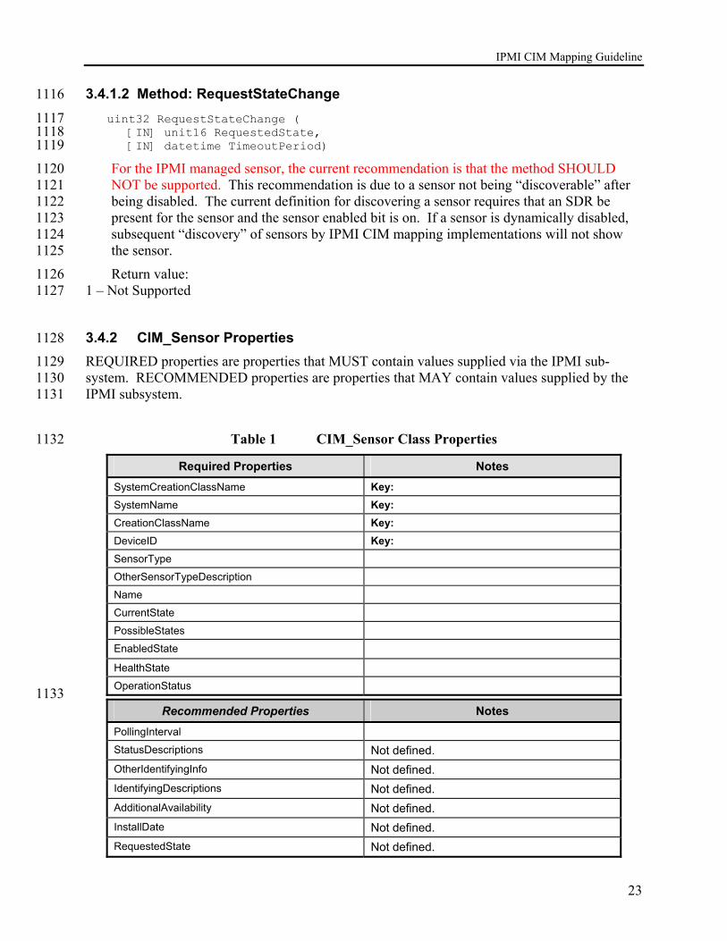
IPMI CIM Mapping Guideline
23
3.4.1.2 Method: RequestStateChange 1116
uint32 RequestStateChange ( 1117 [IN] unit16 RequestedState, 1118 [IN] datetime TimeoutPeriod) 1119
For the IPMI managed sensor, the current recommendation is that the method SHOULD 1120 NOT be supported. This recommendation is due to a sensor not being “discoverable” after 1121 being disabled. The current definition for discovering a sensor requires that an SDR be 1122 present for the sensor and the sensor enabled bit is on. If a sensor is dynamically disabled, 1123 subsequent “discovery” of sensors by IPMI CIM mapping implementations will not show 1124 the sensor. 1125
Return value: 1126 1 – Not Supported 1127
3.4.2 CIM_Sensor Properties 1128 REQUIRED properties are properties that MUST contain values supplied via the IPMI sub-1129 system. RECOMMENDED properties are properties that MAY contain values supplied by the 1130 IPMI subsystem. 1131
Table 1 CIM_Sensor Class Properties 1132
Required Properties Notes SystemCreationClassName Key: SystemName Key: CreationClassName Key: DeviceID Key: SensorType
OtherSensorTypeDescription
Name
CurrentState
PossibleStates
EnabledState HealthState
OperationStatus 1133
Recommended Properties Notes PollingInterval
StatusDescriptions Not defined. OtherIdentifyingInfo Not defined. IdentifyingDescriptions Not defined. AdditionalAvailability Not defined. InstallDate Not defined. RequestedState Not defined.
IPMI CIM Mapping Guideline
24
Recommended Properties Notes TimeOfLastStateChange Not defined. OtherEnabledState Not defined. RequestedState Not defined. EnabledState Not defined. Caption
Description
ElementName
3.4.2.1 CIM_Sensor.SystemCreationClassName 1134 Per the DMTF definition of the class property: The scoping System's CreationClassName. In all 1135 cases this will be the class “CIM_ComputerSystem”. 1136
Formulate as a string: 1137
<”CIM_ComputerSystem”> 1138
3.4.2.2 CIM_Sensor.SystemName 1139 Formulate as a string: 1140
“ComputerSystem.Name, of the ComputerSystem instance, across the SystemDevice 1141 association> 1142
The CIM_ComputerSystem instance supplying the CIM_ComputerSystemName property value 1143 is the CIM_ComputerSystem instance the ‘supervises’ (or ‘owns’) the given CIM_Sensor 1144 instance. Typically, this CIM_ComputerSystem instance represents the management controller 1145 associated with the given sensor. This string value must be found and then copied in to the 1146 CIM_Sensor.SystemName property. Since there is but one instance of a management controller 1147 for most IPMI-compliant devices/systems, this is often quite easy to do. 1148
Some modular systems may support an entire hierarchy of IPMI management controllers. For 1149 instance, the Advanced Telecommunications Architecture (ATCA – also known as PICMG 3.x), 1150 can support shelf management controllers (ShMCs). These are sometimes called Chassis 1151 Management Modules (CMMs – especially for bladed systems). Whatever the nomenclature, 1152 master management controllers often talk to some set of ‘line’ card or ‘blade’ card. Each such 1153 line/blade card can have its own embedded management controller. In turn, these (carrier) cards 1154 might support mezzanine cards (e.g. the ATCA mezzanine card standard). Once again, the 1155 mezzanine cards themselves might support IPMI management controllers (using names like the 1156 integrated platform management controller - IPMC). IPMI was designed to handle such 1157 hierarchical configurations of management controllers (and ‘IPMI message bridging’ amongst 1158 them). 1159
In the presence of a management controller hierarchy, the CIM_Sensor.SystemName value 1160 comes from the particular instance of a CIM_ComputerSystem (representing a management 1161 controller) that has a direct CIM_SystemDevice association with the sensor in question. 1162
IPMI CIM Mapping Guideline
25
3.4.2.3 CIM_Sensor.CreationClassName 1163 As per the DMTF definition of this class property: The name of the class or the subclass used in 1164 the creation of an instance. This will typically be “CIM_Sensor” or “CIM_Numeric_Sensor”. 1165 However, some CIM implementations may include one or more proprietary subclasses of 1166 CIM_Sensor. In these cases the CIM_Sensor.CreationClassName value will be the name 1167 identifying such a subclass. 1168
Formulate as a string: 1169
”CIM_Sensor” or the name of the subclass created 1170
3.4.2.4 CIM_Sensor.DeviceID 1171 If SDR Record Type >= 01h and SDR Record Type <= 02h 1172
The DeviceID is generated from the concatenation of the following fields separated by 1173 periods (".") 1174
SDR Type (1|2) 1175
Sensor Number (SDR type 1|2 table byte 8) 1176
Owner LUN (SDR type 1|2 table byte 7) 1177
Owner ID (SDR type 1|2 table byte 6) 1178
Event/Reading Type Code (hex to string) 1179
Sensor Specific Offset or "99" if none (hex to decimal to string) 1180
Formulate as a string: 1181
(string)(SensorNumber) || “.” || (string)(OwnerLUN) || “.” || (string)(OwnerID) || 1182
(string) (Event/Reading Type Code> || ”.” || 1183
(string) (Sensor Specific Offset or 99 if none) 1184
Examples: 1185
Discrete sensor, Full Record Typ 1, for Processor Sensor 6, LUN 0, Owner ID 1, Offset 1186 07 (Presence Detected). 1187
1.6.0.1.6F.7 1188
Temperature sensor, Compact record Type 2, for Fan Sensor 8, LUN 0, Owner ID 2, no 1189 offset 1190
2.8.0.2.01.99 1191

IPMI CIM Mapping Guideline
26
else if SDR Record Type == C0h 1192
The DeviceID is generated from the concatenation of the following fields separated by 1193 periods (".") 1194
SDR Type (12) 1195
SDR Record ID(SDR table byte 1 and 2) 1196
Formulate as a string: 1197
(string) 12 || (string) (SDR Record ID(SDR Table byte 1 and 2)) 1198
Example: 1199
OEM SDR with Record ID 0102h 1200
12.258 1201
3.4.2.5 CIM_Sensor.ElementName and CIM_Sensor.Name 1202 if SDR Record Type >= 01h and SDR Record Type <= 02h 1203
Formulate as a string: 1204
(string)<IPMI v1.5 SDR Record Type 01h or 02h, SDR entry bytes 49+, see IPMI v1.5 1205 Table 37-1> || “(” || (string)(SensorNumber) || “.” || (string)(OwnerLUN) || “.” || 1206 string)(OwnerID) || “)” 1207
Examples: 1208
GeneralChassis1Intrusion(8.0.2) 1209
DriveBay3Intrusion(7.0.1) 1210
Processor4ThermalTrip(4.0.6) 1211
LAN2Leash(8.0.8) 1212
PUnit1OutputVoltage(6.0.1) 1213
CPU1T(13.1.3) 1214
else if SDR Record Type == C0h 1215
Formulate as a string: 1216
“OEM Record” || ”(“ || (string)(ManufacturerID) || “)” 1217
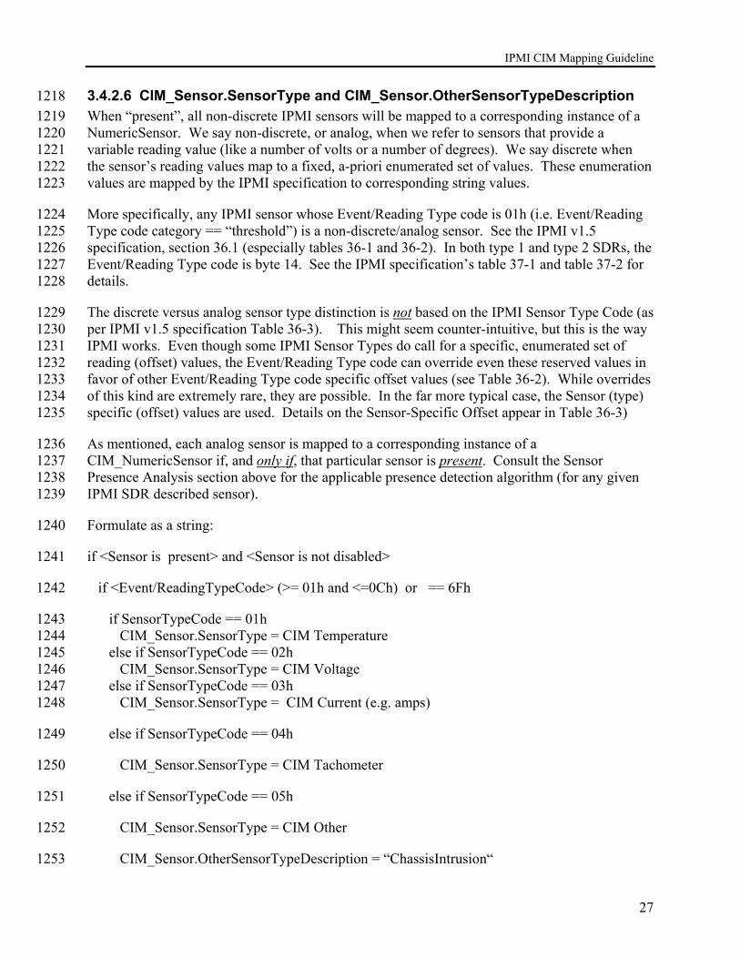
IPMI CIM Mapping Guideline
27
3.4.2.6 CIM_Sensor.SensorType and CIM_Sensor.OtherSensorTypeDescription 1218 When “present”, all non-discrete IPMI sensors will be mapped to a corresponding instance of a 1219 NumericSensor. We say non-discrete, or analog, when we refer to sensors that provide a 1220 variable reading value (like a number of volts or a number of degrees). We say discrete when 1221 the sensor’s reading values map to a fixed, a-priori enumerated set of values. These enumeration 1222 values are mapped by the IPMI specification to corresponding string values. 1223
More specifically, any IPMI sensor whose Event/Reading Type code is 01h (i.e. Event/Reading 1224 Type code category == “threshold”) is a non-discrete/analog sensor. See the IPMI v1.5 1225 specification, section 36.1 (especially tables 36-1 and 36-2). In both type 1 and type 2 SDRs, the 1226 Event/Reading Type code is byte 14. See the IPMI specification’s table 37-1 and table 37-2 for 1227 details. 1228
The discrete versus analog sensor type distinction is not based on the IPMI Sensor Type Code (as 1229 per IPMI v1.5 specification Table 36-3). This might seem counter-intuitive, but this is the way 1230 IPMI works. Even though some IPMI Sensor Types do call for a specific, enumerated set of 1231 reading (offset) values, the Event/Reading Type code can override even these reserved values in 1232 favor of other Event/Reading Type code specific offset values (see Table 36-2). While overrides 1233 of this kind are extremely rare, they are possible. In the far more typical case, the Sensor (type) 1234 specific (offset) values are used. Details on the Sensor-Specific Offset appear in Table 36-3) 1235
As mentioned, each analog sensor is mapped to a corresponding instance of a 1236 CIM_NumericSensor if, and only if, that particular sensor is present. Consult the Sensor 1237 Presence Analysis section above for the applicable presence detection algorithm (for any given 1238 IPMI SDR described sensor). 1239
Formulate as a string: 1240
if <Sensor is present> and <Sensor is not disabled> 1241
if <Event/ReadingTypeCode> (>= 01h and <=0Ch) or == 6Fh 1242
if SensorTypeCode == 01h 1243 CIM_Sensor.SensorType = CIM Temperature 1244 else if SensorTypeCode == 02h 1245 CIM_Sensor.SensorType = CIM Voltage 1246 else if SensorTypeCode == 03h 1247 CIM_Sensor.SensorType = CIM Current (e.g. amps) 1248
else if SensorTypeCode == 04h 1249
CIM_Sensor.SensorType = CIM Tachometer 1250
else if SensorTypeCode == 05h 1251
CIM_Sensor.SensorType = CIM Other 1252
CIM_Sensor.OtherSensorTypeDescription = “ChassisIntrusion“ 1253
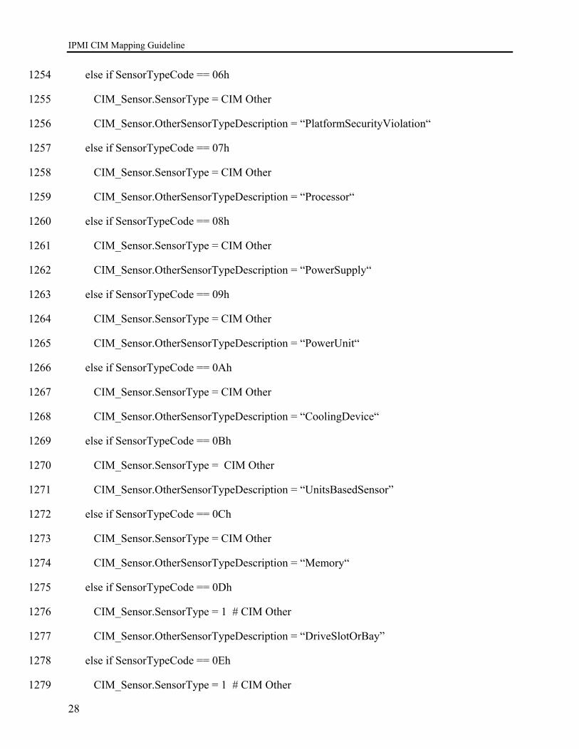
IPMI CIM Mapping Guideline
28
else if SensorTypeCode == 06h 1254
CIM_Sensor.SensorType = CIM Other 1255
CIM_Sensor.OtherSensorTypeDescription = “PlatformSecurityViolation“ 1256
else if SensorTypeCode == 07h 1257
CIM_Sensor.SensorType = CIM Other 1258
CIM_Sensor.OtherSensorTypeDescription = “Processor“ 1259
else if SensorTypeCode == 08h 1260
CIM_Sensor.SensorType = CIM Other 1261
CIM_Sensor.OtherSensorTypeDescription = “PowerSupply“ 1262
else if SensorTypeCode == 09h 1263
CIM_Sensor.SensorType = CIM Other 1264
CIM_Sensor.OtherSensorTypeDescription = “PowerUnit“ 1265
else if SensorTypeCode == 0Ah 1266
CIM_Sensor.SensorType = CIM Other 1267
CIM_Sensor.OtherSensorTypeDescription = “CoolingDevice“ 1268
else if SensorTypeCode == 0Bh 1269
CIM_Sensor.SensorType = CIM Other 1270
CIM_Sensor.OtherSensorTypeDescription = “UnitsBasedSensor” 1271
else if SensorTypeCode == 0Ch 1272
CIM_Sensor.SensorType = CIM Other 1273
CIM_Sensor.OtherSensorTypeDescription = “Memory“ 1274
else if SensorTypeCode == 0Dh 1275
CIM_Sensor.SensorType = 1 # CIM Other 1276
CIM_Sensor.OtherSensorTypeDescription = “DriveSlotOrBay” 1277
else if SensorTypeCode == 0Eh 1278
CIM_Sensor.SensorType = 1 # CIM Other 1279
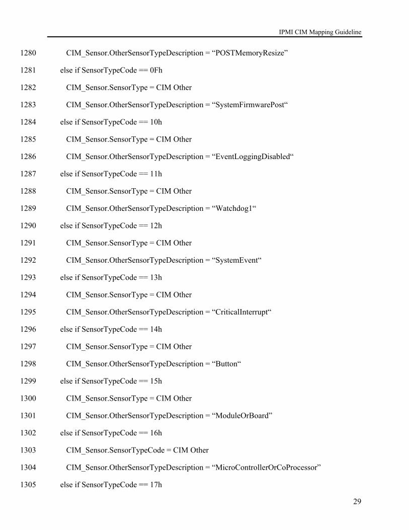
IPMI CIM Mapping Guideline
29
CIM_Sensor.OtherSensorTypeDescription = “POSTMemoryResize” 1280
else if SensorTypeCode == 0Fh 1281
CIM_Sensor.SensorType = CIM Other 1282
CIM_Sensor.OtherSensorTypeDescription = “SystemFirmwarePost“ 1283
else if SensorTypeCode == 10h 1284
CIM_Sensor.SensorType = CIM Other 1285
CIM_Sensor.OtherSensorTypeDescription = “EventLoggingDisabled“ 1286
else if SensorTypeCode == 11h 1287
CIM_Sensor.SensorType = CIM Other 1288
CIM_Sensor.OtherSensorTypeDescription = “Watchdog1“ 1289
else if SensorTypeCode == 12h 1290
CIM_Sensor.SensorType = CIM Other 1291
CIM_Sensor.OtherSensorTypeDescription = “SystemEvent“ 1292
else if SensorTypeCode == 13h 1293
CIM_Sensor.SensorType = CIM Other 1294
CIM_Sensor.OtherSensorTypeDescription = “CriticalInterrupt“ 1295
else if SensorTypeCode == 14h 1296
CIM_Sensor.SensorType = CIM Other 1297
CIM_Sensor.OtherSensorTypeDescription = “Button“ 1298
else if SensorTypeCode == 15h 1299
CIM_Sensor.SensorType = CIM Other 1300
CIM_Sensor.OtherSensorTypeDescription = “ModuleOrBoard” 1301
else if SensorTypeCode == 16h 1302
CIM_Sensor.SensorTypeCode = CIM Other 1303
CIM_Sensor.OtherSensorTypeDescription = “MicroControllerOrCoProcessor” 1304
else if SensorTypeCode == 17h 1305
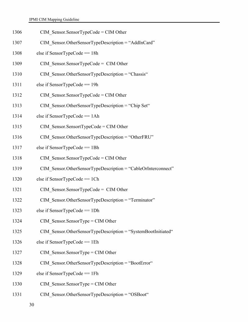
IPMI CIM Mapping Guideline
30
CIM_Sensor.SensorTypeCode = CIM Other 1306
CIM_Sensor.OtherSensorTypeDescription = “AddInCard” 1307
else if SensorTypeCode == 18h 1308
CIM_Sensor.SensorTypeCode = CIM Other 1309
CIM_Sensor.OtherSensorTypeDescription = “Chassis“ 1310
else if SensorTypeCode == 19h 1311
CIM_Sensor.SensorTypeCode = CIM Other 1312
CIM_Sensor.OtherSensorTypeDescription = “Chip Set“ 1313
else if SensorTypeCode == 1Ah 1314
CIM_Sensor.SensortTypeCode = CIM Other 1315
CIM_Sensor.OtherSensorTypeDescription = “OtherFRU” 1316
else if SensorTypeCode == 1Bh 1317
CIM_Sensor.SensorTypeCode = CIM Other 1318
CIM_Sensor.OtherSensorTypeDescription = “CableOrInterconnect” 1319
else if SensorTypeCode == 1Ch 1320
CIM_Sensor.SensorTypeCode = CIM Other 1321
CIM_Sensor.OtherSensorTypeDescription = “Terminator” 1322
else if SensorTypeCode == 1Dh 1323
CIM_Sensor.SensorType = CIM Other 1324
CIM_Sensor.OtherSensorTypeDescription = “SystemBootInitiated“ 1325
else if SensorTypeCode == 1Eh 1326
CIM_Sensor.SensorType = CIM Other 1327
CIM_Sensor.OtherSensorTypeDescription = “BootError“ 1328
else if SensorTypeCode == 1Fh 1329
CIM_Sensor.SensorType = CIM Other 1330
CIM_Sensor.OtherSensorTypeDescription = “OSBoot“ 1331
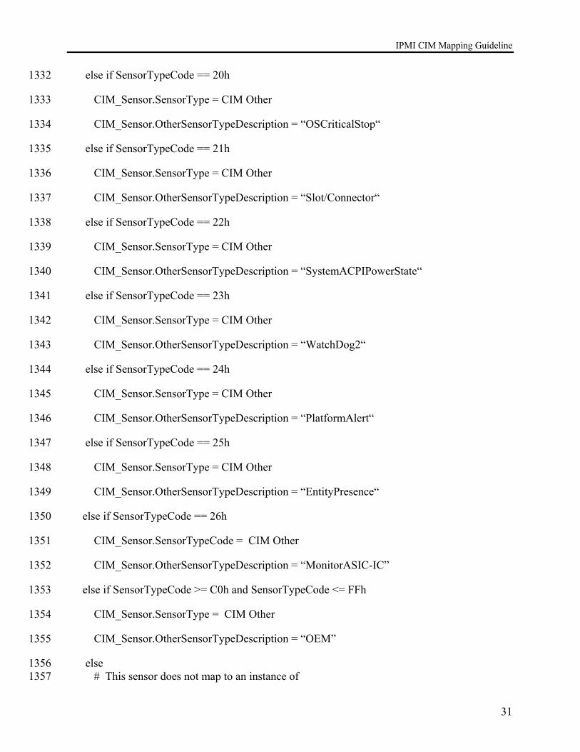
IPMI CIM Mapping Guideline
31
else if SensorTypeCode == 20h 1332
CIM_Sensor.SensorType = CIM Other 1333
CIM_Sensor.OtherSensorTypeDescription = “OSCriticalStop“ 1334
else if SensorTypeCode == 21h 1335
CIM_Sensor.SensorType = CIM Other 1336
CIM_Sensor.OtherSensorTypeDescription = “Slot/Connector“ 1337
else if SensorTypeCode == 22h 1338
CIM_Sensor.SensorType = CIM Other 1339
CIM_Sensor.OtherSensorTypeDescription = “SystemACPIPowerState“ 1340
else if SensorTypeCode == 23h 1341
CIM_Sensor.SensorType = CIM Other 1342
CIM_Sensor.OtherSensorTypeDescription = “WatchDog2“ 1343
else if SensorTypeCode == 24h 1344
CIM_Sensor.SensorType = CIM Other 1345
CIM_Sensor.OtherSensorTypeDescription = “PlatformAlert“ 1346
else if SensorTypeCode == 25h 1347
CIM_Sensor.SensorType = CIM Other 1348
CIM_Sensor.OtherSensorTypeDescription = “EntityPresence“ 1349
else if SensorTypeCode == 26h 1350
CIM_Sensor.SensorTypeCode = CIM Other 1351
CIM_Sensor.OtherSensorTypeDescription = “MonitorASIC-IC” 1352
else if SensorTypeCode >= C0h and SensorTypeCode <= FFh 1353
CIM_Sensor.SensorType = CIM Other 1354
CIM_Sensor.OtherSensorTypeDescription = “OEM” 1355
else 1356 # This sensor does not map to an instance of 1357
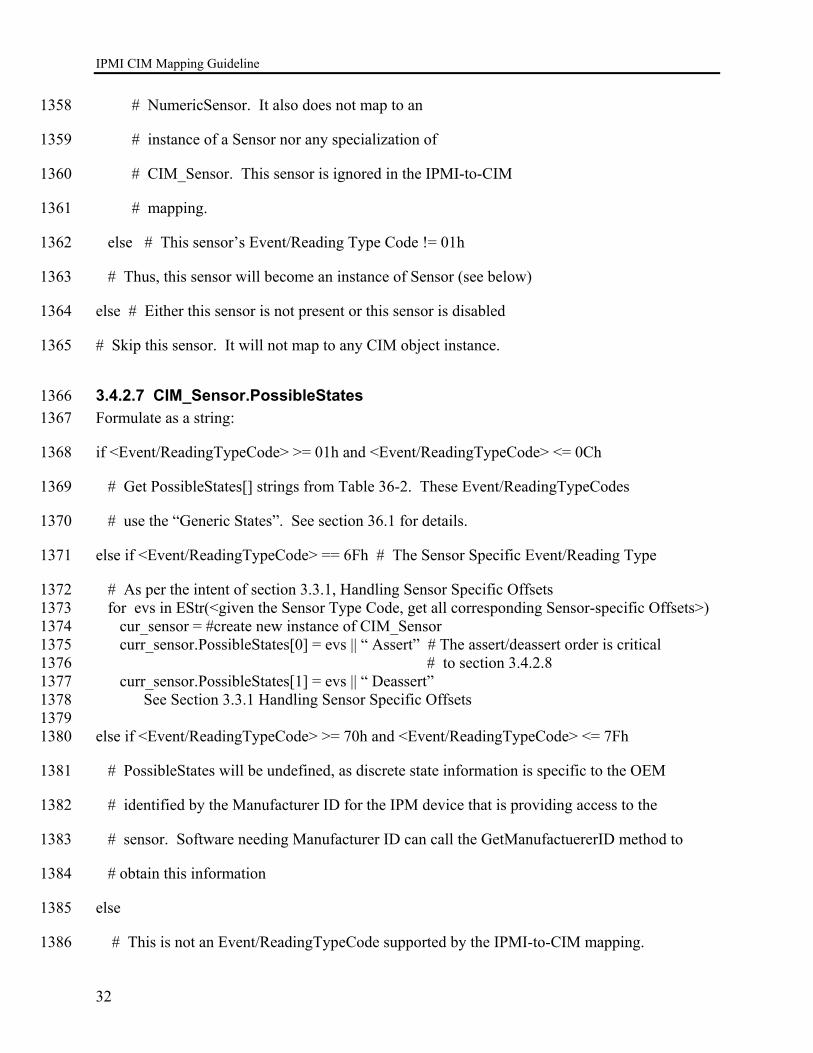
IPMI CIM Mapping Guideline
32
# NumericSensor. It also does not map to an 1358
# instance of a Sensor nor any specialization of 1359
# CIM_Sensor. This sensor is ignored in the IPMI-to-CIM 1360
# mapping. 1361
else # This sensor’s Event/Reading Type Code != 01h 1362
# Thus, this sensor will become an instance of Sensor (see below) 1363
else # Either this sensor is not present or this sensor is disabled 1364
# Skip this sensor. It will not map to any CIM object instance. 1365
3.4.2.7 CIM_Sensor.PossibleStates 1366 Formulate as a string: 1367
if <Event/ReadingTypeCode> >= 01h and <Event/ReadingTypeCode> <= 0Ch 1368
# Get PossibleStates[] strings from Table 36-2. These Event/ReadingTypeCodes 1369
# use the “Generic States”. See section 36.1 for details. 1370
else if <Event/ReadingTypeCode> == 6Fh # The Sensor Specific Event/Reading Type 1371
# As per the intent of section 3.3.1, Handling Sensor Specific Offsets 1372 for evs in EStr(<given the Sensor Type Code, get all corresponding Sensor-specific Offsets>) 1373 cur_sensor = #create new instance of CIM_Sensor 1374 curr_sensor.PossibleStates[0] = evs || “ Assert” # The assert/deassert order is critical 1375 # to section 3.4.2.8 1376 curr_sensor.PossibleStates[1] = evs || “ Deassert” 1377
See Section 3.3.1 Handling Sensor Specific Offsets 1378 1379
else if <Event/ReadingTypeCode> >= 70h and <Event/ReadingTypeCode> <= 7Fh 1380
# PossibleStates will be undefined, as discrete state information is specific to the OEM 1381
# identified by the Manufacturer ID for the IPM device that is providing access to the 1382
# sensor. Software needing Manufacturer ID can call the GetManufactuererID method to 1383
# obtain this information 1384
else 1385
# This is not an Event/ReadingTypeCode supported by the IPMI-to-CIM mapping. 1386

IPMI CIM Mapping Guideline
33
# Skip this sensor. It will not map to a CIM object instance. 1387
3.4.2.8 CIM_Sensor.CurrentState 1388 If the IPMI GetSensorReading command returns a byte 4, then map the bit 1389
# fields of byte 4 to one of the CIM_NumericSensor.PossibleStates above. 1390
# If not, then the CurrentState is “OK”. 1391
# If multiple bits are set in byte 4, See Section 3.3.1 Handling Sensor Specific Offsets. 1392
# Given the IPMI sensor identifier, 1393 # and the Get Sensor Reading Command byte 4/5 response, 1394 # reverse map to find the corresponding instances (plural) of CIM_Sensor. 1395 # Remember that a single IPMI sensor with Sensor Specific Offsets 1396 # can turn into a collection of CIM_Sensor instances – one for asserting 1397 # each sensor specific offset. I’ll call the associated CIM_Sensor instances 1398 # related CIM Sensors. 1399 # 1400 States_Asserted[] = <byte 4 [7:0] from Get Sensor Reading Command & 1401 Byte 5 [6:0] from Get Sensor Reading Command> 1402 Related_Sensors[] = sort-by-IPMI-offset<related_CIM_Sensors> 1403 i=0; 1404 for current_sensor in <Related_Sensors> 1405 if Sates_Asserted[i] 1406 current_sensor.CurrentState = current_sensor.PossibleState[0] # Assert 1407 else 1408 current_sensor.CurrentState = current_sensor.PossibleState[1] # Deassert 1409
1410
3.4.2.9 CIM_Sensor.Caption 1411 if SDR Record Type >= 01h and SDR Record Type <= 02h 1412
Formulate as a string: 1413
(string)TruncAt(64, EStr(CIM_Sensor.SensorType)) || “(” || (string)(SensorNumber) || “.” 1414 || (string)(OwnerLUN) || “.” || (string)(OwnerID) || “)” ) 1415
Example: 1416
Voltage(6.0.1) 1417
Temperature(13.1.3) 1418
else if SDR Record Type == C0h 1419
Formulate as a string: 1420
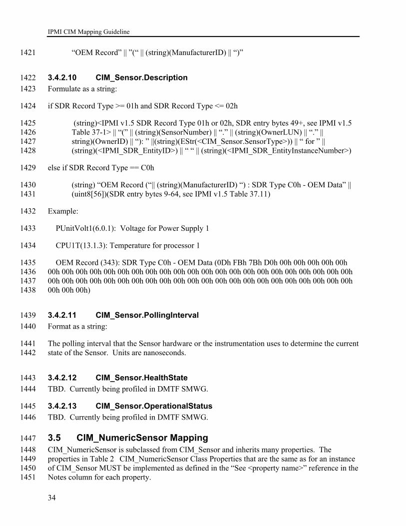
IPMI CIM Mapping Guideline
34
“OEM Record” || ”(“ || (string)(ManufacturerID) || “)” 1421
3.4.2.10 CIM_Sensor.Description 1422 Formulate as a string: 1423
if SDR Record Type >= 01h and SDR Record Type <= 02h 1424
(string)<IPMI v1.5 SDR Record Type 01h or 02h, SDR entry bytes 49+, see IPMI v1.5 1425 Table 37-1> || “(” || (string)(SensorNumber) || “.” || (string)(OwnerLUN) || “.” || 1426 string)(OwnerID) || “): ” ||(string)(EStr(<CIM_Sensor.SensorType>)) || “ for ” || 1427 (string)(<IPMI_SDR_EntityID>) || “ “ || (string)(<IPMI_SDR_EntityInstanceNumber>) 1428
else if SDR Record Type == C0h 1429
(string) “OEM Record (“|| (string)(ManufacturerID) “) : SDR Type C0h - OEM Data” || 1430 (uint8[56])(SDR entry bytes 9-64, see IPMI v1.5 Table 37.11) 1431
Example: 1432
PUnitVolt1(6.0.1): Voltage for Power Supply 1 1433
CPU1T(13.1.3): Temperature for processor 1 1434
OEM Record (343): SDR Type C0h - OEM Data (0Dh FBh 7Bh D0h 00h 00h 00h 00h 00h 1435 00h 00h 00h 00h 00h 00h 00h 00h 00h 00h 00h 00h 00h 00h 00h 00h 00h 00h 00h 00h 00h 00h 1436 00h 00h 00h 00h 00h 00h 00h 00h 00h 00h 00h 00h 00h 00h 00h 00h 00h 00h 00h 00h 00h 00h 1437 00h 00h 00h) 1438
3.4.2.11 CIM_Sensor.PollingInterval 1439 Format as a string: 1440
The polling interval that the Sensor hardware or the instrumentation uses to determine the current 1441 state of the Sensor. Units are nanoseconds. 1442
3.4.2.12 CIM_Sensor.HealthState 1443 TBD. Currently being profiled in DMTF SMWG. 1444
3.4.2.13 CIM_Sensor.OperationalStatus 1445 TBD. Currently being profiled in DMTF SMWG. 1446
3.5 CIM_NumericSensor Mapping 1447 CIM_NumericSensor is subclassed from CIM_Sensor and inherits many properties. The 1448 properties in Table 2 CIM_NumericSensor Class Properties that are the same as for an instance 1449 of CIM_Sensor MUST be implemented as defined in the “See <property name>” reference in the 1450 Notes column for each property. 1451

IPMI CIM Mapping Guideline
35
3.5.1 CIM_NumericSensor.Properties 1452 REQUIRED properties are properties that MUST be present. RECOMMENDED properties are 1453 properties that MAY be present. For example, there may be properties that are only filled out in 1454 special configurations of the CIM Schema. 1455
Properties that listed in the Required section in Table 2 below MUST be implemented as defined 1456 in the subsection following this table unless the Notes column for each property specifies the 1457 defining reference. 1458
Table 2 CIM_NumericSensor Class Properties 1459
Required Properties Notes SystemCreationClassName Key: See CIM_Sensor.SystemCreationClassName
mapping
SystemName Key: See CIM_Sensor.SystemName Mapping
CreationClassName Key: See CIM_Sensor.CreationClassName mapping
DeviceID Key: See CIM_Sensor.DeviceID mapping
SensorType See CIM_Sensor.SensorType mapping
OtherSensorTypeDescription See CIM_Sensor.OtherSensorTypeDescription mapping
Name See CIM_Sensor.SystemCreationClassName mapping
HealthState See CIM_Sensor.HealthStatus mapping
OperationStatus See CIM_Sensor.OperationStatus mapping
CurrentReading
BaseUnits
UnitModifier
RateUnits 1460
Recommended Properties Notes NominalReading
NormalMax
NormalMin
MaxReadable
MinReadable
Resolution
Accuracy
IsLinear Hysterisis
SupportedThresholds
EnableThresholds
SettableThresholds
PollingInterval See CIM_Sensor.PollingInterval
PossibleStates See CIM_Sensor.PossibleStates mapping

IPMI CIM Mapping Guideline
36
Recommended Properties Notes CurrentState See CIM_Sensor.CurrentState mapping
Caption See CIM_Sensor.Caption mapping
Description See CIM_Sensor.Description mapping
ElementName See CIM_Sensor.ElementName mapping
StatusDescriptions Not defined.
LowerThresholdNonCritical UpperThresholdNonCritical LowerThresholdCritical UpperThresholdCritical LowerThresholdFatal UpperThresholdFatal RequestedState Not defined. EnabledState Not defined. TimeOfLastStateChange Not defined. OtherEnabledState Not defined.
1461
3.5.1.1 NumericSensor.CurrentReading 1462 The current value indicated by the Numeric Sensor. 1463
3.5.1.2 NumericSensor.UnitModifier, BaseUnits, And RateUnits 1464 We must do more than just map IPMI sensor’s with an obviously matching IPMI Sensor Unit 1465 Type Code. An obvious match would be IPMI ‘seconds’ matching to CIM_Sensor.BaseUnits == 1466 ‘seconds’. Scaling issues are less obvious. For example, IPMI ‘milliseconds’ must map to 1467 CIM_Sensor.BaseUnits = ‘seconds’ with a corresponding CIM_Sensor.UnitModfier = -3. The 1468 scaling required might sometimes be a bit less trivial. Still, all IPMI “BaseUnits” must be 1469 mapped to corresponding CIM “BaseUnits”. 1470
CIM represents floating point values as signed integers (sint32) that are scaled. IPMI tends to 1471 use floating point numeric representations (e.g. IEEE 754/854). To map these into signed 1472 integers, we’ll just assume a default “precision” value of “-2” (for the CIM member 1473 “UnitModifier”). We’ll round the IPMI floating point value appropriately and then convert it to 1474 integer required. Recall that a CIM UnitModifer of -2 means that the CIM CurrentReading will 1475 be will multiplied by 0.01 (10-2). So a CurrentReading of 333, where the CIM BaseUnits is 1476 “Voltage”, means that the true current reading is 3.33v. 1477
The RateUnits from the IPMI SDR match one-to-one with the enumerated 1478 CIM_Sensor.RateUnits. The last three CIM_Sensor.RateUnits are not used by IPMI (e.g. “per 1479 week”, “per month”, “per year”). 1480
Examples: BaseUnits 1481
EStr(5) == “Volts” 1482
IPMI CIM Mapping Guideline
37
EStr(3) == “Degrees F” 1483
Examples: RateUnits 1484
EStr(0) == “None” 1485
EStr(1) == “Per Microsecond” 1486
EStr(2) == “Per Millisecond 1487
EStr(3) == “Per Second” 1488
EStr(4) == “Per Minute” 1489
EStr(5) == “Per Hour” 1490
EStr(6) == “Per Day” 1491
3.5.1.3 NumericSensor.NominalReading 1492 NominalReading indicates the 'normal' or expected value for the NumericSensor. 1493
3.5.1.4 NumericSensor.NormalMax 1494 NormalMax provides guidance for the user as to the normal maximum range for the 1495 NumericSensor 1496
3.5.1.5 NumericSensor.NormalMin 1497 NormalMin provides guidance for the user as to the normal minimum range for the 1498 NumericSensor. 1499
3.5.1.6 NumericSensor.MaxReadable 1500 MaxReadable indicates the largest value of the measured property that can be read by the 1501 NumericSensor. 1502
3.5.1.7 NumericSensor.MinReadable 1503 MinReadable indicates the smallest value of the measured property that can be read by the 1504 NumericSensor. 1505
3.5.1.8 NumericSensor.Resolution 1506 Resolution indicates the ability of the Sensor to resolve differences in the measured property. 1507 The units for this measurement are determined by "BaseUnit*UnitModifier/RateUnit. 1508
IPMI CIM Mapping Guideline
38
3.5.1.9 NumericSensor.Accuracy 1509 Indicates the accuracy of the Sensor for the measured property. Its value is recorded as 1510 plus/minus hundredths of a percent. Accuracy, along with Resolution, is used to calculate the 1511 actual value of the measured physical property. Accuracy may vary depending on whether the 1512 Device is linear over its dynamic range. 1513
Example value: 0 1514
3.5.1.10 NumericSensor.IsLinear 1515 Indicates that the Sensor is linear over its dynamic range. 1516
Example value: TRUE 1517
3.5.1.11 NumericSensor.Hysteresis 1518 Indicates the margin built around the thresholds. This margin prevents unnecessary state changes 1519 when the Sensor reading may fluctuate very close to its thresholds. This could be due to the 1520 Sensor's tolerance/accuracy/resolution or due to environmental factors. Once a threshold is 1521 crossed, the state of the Sensor should change. However, the state should not fluctuate between 1522 the old and new states unless the Sensor's change in the reading exceeds the hysteresis value. The 1523 units for this measurement are determined by BaseUnit*UnitModifier/RateUnit. 1524
Fixed value of: 0 1525
3.5.1.12 NumericSensor.SupportedThresholds 1526 If supported by BMC (from SDR). 1527
3.5.1.13 NumericSensor.EnableThresholds 1528 If supported by BMC (from SDR). 1529
3.5.1.14 NumericSensor.SettableThresholds 1530 If supported by BMC (from SDR). 1531
3.5.1.15 NumericSensor.LowerThresholdNonCritical 1532 The Sensor's threshold values specify the ranges (min and max values) for determining whether 1533 the Sensor is operating under Normal, NonCritical, Critical or Fatal conditions. If Current 1534 Reading is between LowerThresholdNonCritical and Upper ThresholdNonCritical, then the 1535 Sensor is reporting a normal value. If CurrentReading is between LowerThresholdNonCritical 1536 and LowerThresholdCritical, then the CurrentState is NonCritical. 1537
Example value: 50 1538
IPMI CIM Mapping Guideline
39
3.5.1.16 NumericSensor.UpperThresholdNonCritical 1539 The Sensor's threshold values specify the ranges (min and max values) for determining whether 1540 the Sensor is operating under Normal, NonCritical, Critical or Fatal conditions. If the 1541 CurrentReading is between LowerThresholdNonCritical and UpperThresholdNonCritical, then 1542 the Sensor is reporting a normal value. If the CurrentReading is between UpperThreshold 1543 NonCritical and UpperThresholdCritical, then the CurrentState is NonCritical. 1544 Example value: 500 1545
3.5.1.17 NumericSensor.LowerThresholdCritical 1546 The Sensor's threshold values specify the ranges (min and max values) for determining whether 1547 the Sensor is operating under Normal, NonCritical, Critical or Fatal conditions. If the 1548 CurrentReading is between LowerThresholdCritical and Lower ThresholdFatal, then the 1549 CurrentState is Critical. 1550
Example value: -1200 1551
3.5.1.18 NumericSensor.UpperThresholdCritical 1552 The Sensor's threshold values specify the ranges (min and max values) for determining whether 1553 the Sensor is operating under Normal, NonCritical, Critical or Fatal conditions. If the 1554 CurrentReading is between UpperThresholdCritical and Upper ThresholdFatal, then the 1555 CurrentState is Critical. 1556
Example value: 550 1557
3.5.1.19 NumericSensor.LowerThresholdFatal 1558 The Sensor's threshold values specify the ranges (min and max values) for determining whether 1559 the Sensor is operating under Normal, NonCritical, Critical or Fatal conditions. If the 1560 CurrentReading is below LowerThresholdFatal, then the Current State is Fatal. 1561
Example value: -1279 1562
3.5.1.20 NumericSensor.UpperThresholdFatal 1563 The Sensor's threshold values specify the ranges (min and max values) for determining whether 1564 the Sensor is operating under Normal, NonCritical, Critical or Fatal conditions. If the 1565 CurrentReading is above UpperThresholdFatal, then the Current State is Fatal. 1566
Example value: 1270 1567
1568
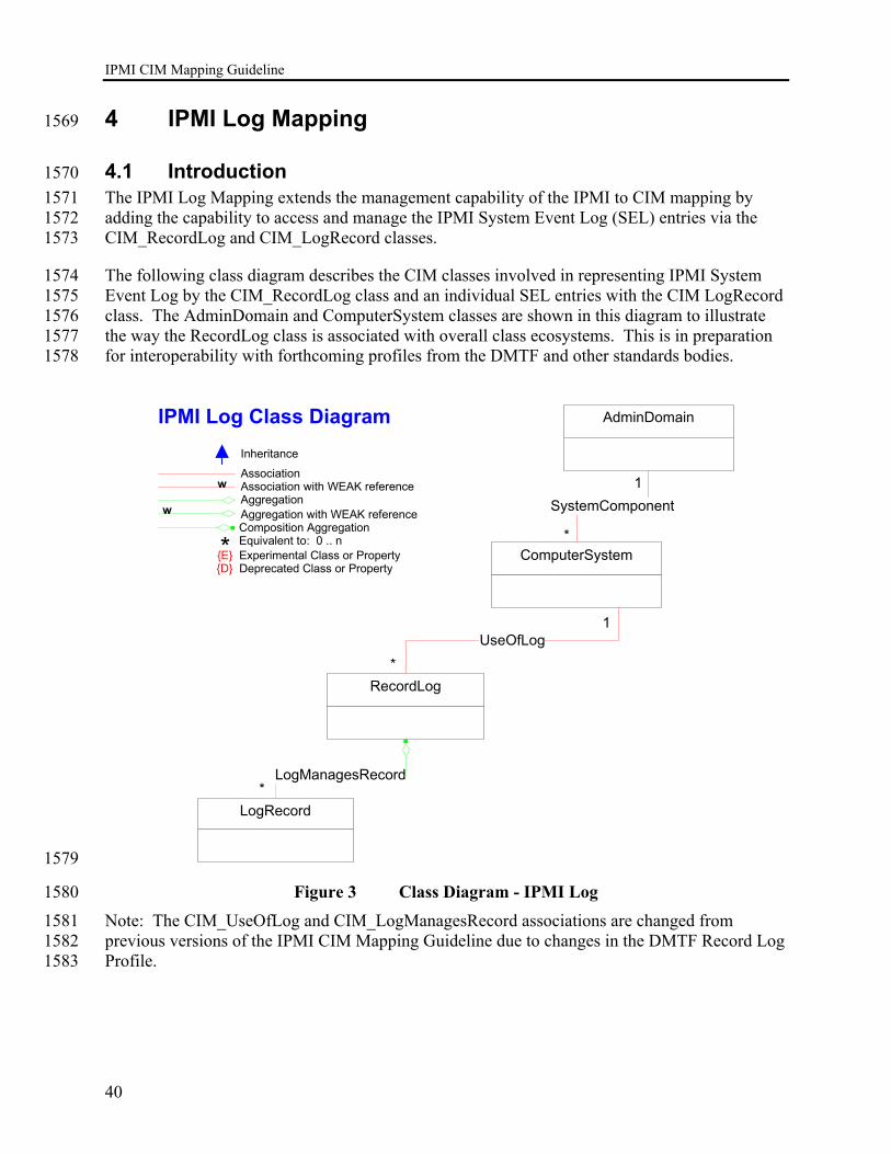
IPMI CIM Mapping Guideline
40
4 IPMI Log Mapping 1569
4.1 Introduction 1570 The IPMI Log Mapping extends the management capability of the IPMI to CIM mapping by 1571 adding the capability to access and manage the IPMI System Event Log (SEL) entries via the 1572 CIM_RecordLog and CIM_LogRecord classes. 1573
The following class diagram describes the CIM classes involved in representing IPMI System 1574 Event Log by the CIM_RecordLog class and an individual SEL entries with the CIM LogRecord 1575 class. The AdminDomain and ComputerSystem classes are shown in this diagram to illustrate 1576 the way the RecordLog class is associated with overall class ecosystems. This is in preparation 1577 for interoperability with forthcoming profiles from the DMTF and other standards bodies. 1578
ComputerSystem
LogManagesRecord
LogRecord
UseOfLog
Association
AggregationAssociation with WEAK reference
Inheritance
Aggregation with WEAK reference
w
w
* Equivalent to: 0 .. nComposition Aggregation
{E} Experimental Class or Property{D} Deprecated Class or Property
IPMI Log Class Diagram
RecordLog
AdminDomain
SystemComponent
*
*
*
1
1
1579
Figure 3 Class Diagram - IPMI Log 1580 Note: The CIM_UseOfLog and CIM_LogManagesRecord associations are changed from 1581 previous versions of the IPMI CIM Mapping Guideline due to changes in the DMTF Record Log 1582 Profile. 1583
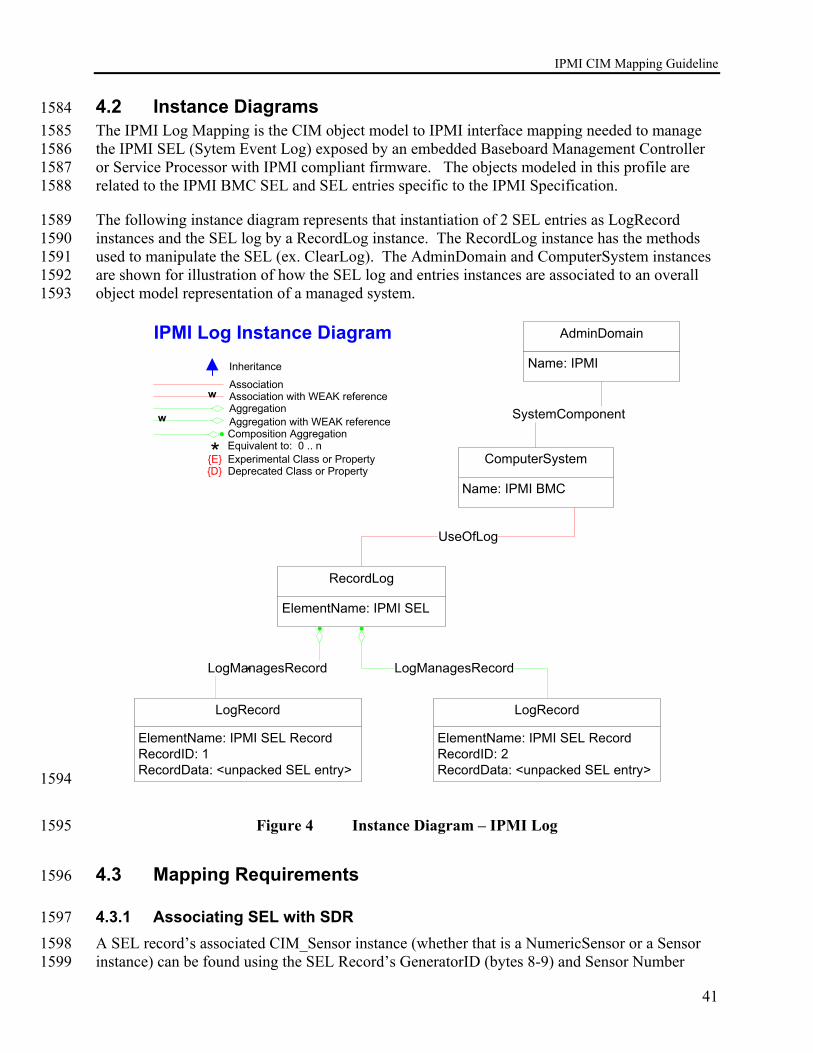
IPMI CIM Mapping Guideline
41
4.2 Instance Diagrams 1584 The IPMI Log Mapping is the CIM object model to IPMI interface mapping needed to manage 1585 the IPMI SEL (Sytem Event Log) exposed by an embedded Baseboard Management Controller 1586 or Service Processor with IPMI compliant firmware. The objects modeled in this profile are 1587 related to the IPMI BMC SEL and SEL entries specific to the IPMI Specification. 1588
The following instance diagram represents that instantiation of 2 SEL entries as LogRecord 1589 instances and the SEL log by a RecordLog instance. The RecordLog instance has the methods 1590 used to manipulate the SEL (ex. ClearLog). The AdminDomain and ComputerSystem instances 1591 are shown for illustration of how the SEL log and entries instances are associated to an overall 1592 object model representation of a managed system. 1593
ComputerSystem
Name: IPMI BMC
LogManagesRecord
ElementName: IPMI SEL RecordRecordID: 1RecordData: <unpacked SEL entry>
LogRecord
UseOfLog
Association
AggregationAssociation with WEAK reference
Inheritance
Aggregation with WEAK reference
w
w
* Equivalent to: 0 .. nComposition Aggregation
{E} Experimental Class or Property{D} Deprecated Class or Property
IPMI Log Instance Diagram
ElementName: IPMI SEL
RecordLog
AdminDomain
Name: IPMI
SystemComponent
*
ElementName: IPMI SEL RecordRecordID: 2RecordData: <unpacked SEL entry>
LogRecord
LogManagesRecord
1594
Figure 4 Instance Diagram – IPMI Log 1595
4.3 Mapping Requirements 1596
4.3.1 Associating SEL with SDR 1597 A SEL record’s associated CIM_Sensor instance (whether that is a NumericSensor or a Sensor 1598 instance) can be found using the SEL Record’s GeneratorID (bytes 8-9) and Sensor Number 1599

IPMI CIM Mapping Guideline
42
(byte 12). See Table 26-1 for details. This SEL data maps to the CIM_Sensor.DeviceID key 1600 value (as defined in the IPMI-to-CIM sensor mapping document). Once this Sensor key string is 1601 extracted from the SEL entry in question, the corresponding CIM_Sensor instance can be found. 1602
Behind the scenes, the corresponding CIM_Sensor maps to a corresponding IPMI SDR record 1603 (or either type 1 or type 2). This indirectly corresponding SDR record must also be found in 1604 order to extract the IPMI_SDR_EntityID and IPMI_SDR_EntityInstanceNumber mentioned 1605 above. 1606
We refer to the CIM_Sensor instance above because CIM_Sensor is a common base class for 1607 both NumericSensor and Sensor (as “trivially derived” for this IPMI-to-CIM mapping). 1608
4.4 CIM_RecordLog Mapping 1609
4.4.1 CIM_RecordLog.Methods 1610
4.4.1.1 Method: ClearLog 1611
uint32 ClearLog() 1612
MUST delete all SEL records: 1613
An application clearing the SEL should utilize the recommended algorithm described below: 1614
a) first check to see if SEL is empty by checking the number of records using "Get SEL 1615 Info" 1616
b) if already empty, you're done 1617
c) if SEL not empty, use "Clear SEL" to see if erase is already in progress (in case Get 1618 SEL Info doesn't return correct status) 1619
d) if erase already in progress then wait (and potentially time out) and exit 1620
e) otherwise (if SEL is not empty) issue the Clear SEL command, then wait (and 1621 potentially time out) and exit 1622
Note: Originally, the ClearLog method on the MessageLog class would issue an IPMI 1623 request to clear the log and return success. But the log may not have actually have cleared 1624 by the time success is returned. The change made was to issue the clear request and spin for 1625 sometime checking if the operation was still in progress. After some period, the operation 1626 will timeout and a timeout error is returned to the client. This means the client needs to call 1627 ClearLog again (and also spin). This scenario is addressed by having the application utilize 1628 the algorithm described above. 1629
Return value: 1630 0 – Completed with no error 1631 1 – Not Supported 1632 2 – Unspecified Error 1633 3 – Timeout 1634 4 – Failed 1635 5 – Invalid Parameter 1636

IPMI CIM Mapping Guideline
43
6..0x0FFF – DMTF_Reserved 1637 0x1000..0x7FFF – Method_Reserved 1638 0x8000.. – Vendor_Reserved 1639
4.4.1.2 Method: RequestStateChange 1640
uint32 RequestStateChange ( 1641 [IN] unit16 RequestedState, 1642 [IN] datetime TimeoutPeriod) 1643
For the IPMI SEL log, the action this method takes on the log is to freeze or stop the log if 1644 the log from accepting further input if the RequestedState parameter is “Disabled”. If the 1645 RequestedState parameter is “Enabled”, the IPMI SEL log is unfrozen or will continue to 1646 accept log entries in the normal fashion. Not all IPMI implementations support the freezing 1647 of the IPMI SEL log and these implementation will need to return “Not Supported” if the 1648 RequestStateChange method is invoked. 1649
Return value: 1650
0 – Completed with no error 1651 1 – Not Supported 1652 2 – Unspecified Error 1653 3 – Timeout 1654 4 – Failed 1655 5 – Invalid Parameter 1656 6..0x0FFF – DMTF_Reserved 1657 0x1000..0x7FFF – Method_Reserved 1658 0x8000.. – Vendor_Reserved 1659
4.4.2 CIM_RecordLog.Properties 1660 REQUIRED properties are properties that MUST be present. RECOMMENDED properties are 1661 properties that MAY be present. For example, there may be properties that are only filled out in 1662 special configurations of the CIM Schema. 1663
Properties that listed in the Required section in Table 2 below MUST be implemented as defined 1664 in the subsections following this table unless the Notes column for each property specifies the 1665 defining reference. 1666
Table 3 CIM_RecordLog Class Properties 1667
Required Properties Notes InstanceID Key:
Name MaxNumberOfRecords
CurrentNumberOfRecords
EnabledState
OperationalStatus
HealthState

IPMI CIM Mapping Guideline
44
1668 Recommended Properties Notes
OtherEnabledState Not defined. RequestedState Not defined. EnabledDefault Not defined. TimeOfLastStateChange Not defined. InstallDate Not defined. StatusDescriptions Not defined. Caption
Description
ElementName
1669
The following subsections describe procedures for generating values for various properties of 1670 CIM classes required in this profile. 1671
4.4.2.1 CIM_RecordLog.InstanceID 1672 Per the DMTF definition: In order to ensure uniqueness within the NameSpace, the value of 1673 InstanceID SHOULD be constructed using the following ’ preferred ’ algorithm: < OrgID > : < 1674 LocalID > Where < OrgID > and < LocalID > are separated by a colon ’ : ’. 1675
Formulate as a string: 1676
<”IPMI” || “:” || < ComputerSystem.Name of the ComputerSystem instance of the one 1677 associated BMC > || “ SEL Log”> 1678
If there are several BMC's in the same namespace, unique names for the BMC’s need to be 1679 generated in order to distinguish between the different instantiations of RecordLog. The name of 1680 the BMC can be formulated by instrumentation using unique identifying values obtained from 1681 the BMC or derived from intrumentation access deviations. 1682
4.4.2.2 CIM_RecordLog.Name 1683 Fixed value of “IPMI SEL” 1684
4.4.2.3 CIM_RecordLog.MaxNumberOfRecords 1685 Calculated by instrumentation using the following approach: 1686
The maximum number of SEL records can be computed by issuing the Get_Sel_Allocation 1687 command and using the response data. Dividing the number of free allocation units (bytes 4,5) 1688 by the maximum record size in allocation units (byte 10) will provide the maximum number of 1689 records. In the event that Get_Sel_Allocation command is not supported, the value should be set 1690 to 0. 1691
IPMI CIM Mapping Guideline
45
4.4.2.4 CIM_RecordLog. CurrentNumberOfRecords 1692 Calculated by instrumentation using the following approach:. 1693
The current number of log records can be determined by issuing a Get_Sel_Info command and 1694 examining the number of log entries (bytes 3,4) in the response data 1695
4.4.2.5 CIM_RecordLog.EnabledState 1696 Per definition in CIM mof: EnabledState is an integer enumeration that indicates the 1697 enabled/disabled states of an element. For the IPMI mapping, the value for EnabledState can 1698 only be “Enabled” and “Disabled”. Enabled indicates the SEL is active and accepting new 1699 entries. Disabled indicates the log is “frozen” or full. Frozen is when the SEL is 1700 programmatically suspended to not accept further entries and is available in some IPMI 1701 implementations (See the RequestStateChange method definition). 1702
Formulate as an integer: 1703
2 – Enabled 1704
3 - Disabled 1705
4.4.2.6 CIM_RecordLog.HealthState 1706 TBD. Currently being profiled in DMTF SMWG. 1707
4.4.2.7 CIM_RecordLog.OperationalStatus 1708 TBD. Currently being profiled in DMTF SMWG. 1709
4.4.2.8 CIM_RecordLog. Caption 1710 Fixed value of “IPMI SEL” 1711
4.4.2.9 CIM_RecordLog. Description 1712 Fixed value of “IPMI SEL” 1713
4.4.2.10 CIM_RecordLog. ElementName 1714 Fixed value of “IPMI SEL” 1715
4.5 CIM_LogRecord Mapping 1716
4.5.1 CIM_LogRecord Methods 1717 None Defined. 1718
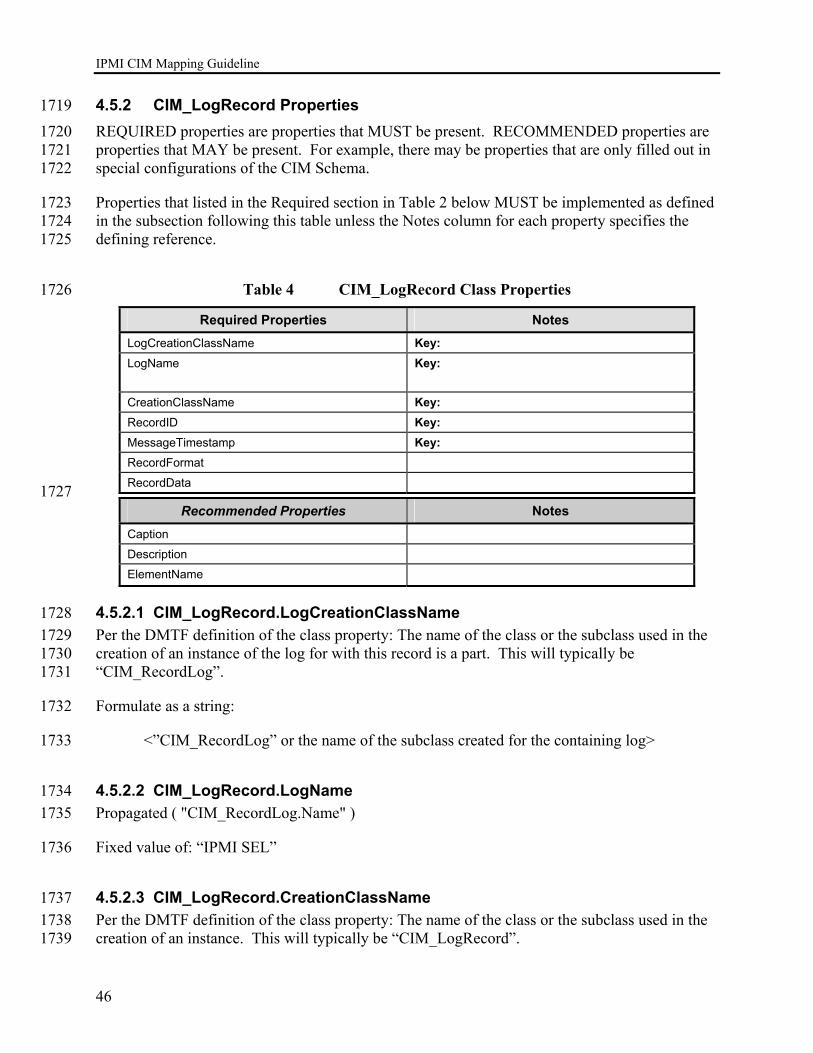
IPMI CIM Mapping Guideline
46
4.5.2 CIM_LogRecord Properties 1719 REQUIRED properties are properties that MUST be present. RECOMMENDED properties are 1720 properties that MAY be present. For example, there may be properties that are only filled out in 1721 special configurations of the CIM Schema. 1722
Properties that listed in the Required section in Table 2 below MUST be implemented as defined 1723 in the subsection following this table unless the Notes column for each property specifies the 1724 defining reference. 1725
Table 4 CIM_LogRecord Class Properties 1726
Required Properties Notes LogCreationClassName Key: LogName Key:
CreationClassName Key: RecordID Key: MessageTimestamp Key: RecordFormat
RecordData 1727
Recommended Properties Notes Caption
Description
ElementName
4.5.2.1 CIM_LogRecord.LogCreationClassName 1728 Per the DMTF definition of the class property: The name of the class or the subclass used in the 1729 creation of an instance of the log for with this record is a part. This will typically be 1730 “CIM_RecordLog”. 1731
Formulate as a string: 1732
<”CIM_RecordLog” or the name of the subclass created for the containing log> 1733
4.5.2.2 CIM_LogRecord.LogName 1734 Propagated ( "CIM_RecordLog.Name" ) 1735
Fixed value of: “IPMI SEL” 1736
4.5.2.3 CIM_LogRecord.CreationClassName 1737 Per the DMTF definition of the class property: The name of the class or the subclass used in the 1738 creation of an instance. This will typically be “CIM_LogRecord”. 1739

IPMI CIM Mapping Guideline
47
Formulate as a string: 1740
<”CIM_LogRecord”> 1741
4.5.2.4 CIM_LogRecord.RecordID 1742 RecordID is a Key and must not be Null. The value will be populated with the IPMI SEL 1743 Record ID. Used in conjunction with the MessageTimestamp, must uniquely identify an 1744 instance of LogRecord that is associated via RecordInLog to the containing instance of 1745 RecordLog representing the SEL. 1746
Formulate as a string: 1747
<SEL Record ID as passed by the Get_SEL_Entry IPMI command> 1748
4.5.2.5 CIM_LogRecord. MessageTimestamp 1749 This value is the timestamp of the SEL entry plus an offset to GMT. There is an assumption that 1750 the BMC time will be set by the system management software running “in-band” in the managed 1751 system that the BMC resides. In band instrumentation will generate the GMT offset required by 1752 this data type by discerning the timezone that the managed system is in and producing the 1753 necessary offset. Out-of-band instrumentation doing CIM mapping will need to determine the 1754 difference with the BMC time and add that difference to the offset for the timezone the out-of-1755 band client is in. 1756
Formulate as a string using the datetime data type as defined by the DMTF: 1757
Example value: “20040924152230.000000+480” 1758
For non-timestamped OEM SEL, this property is set to ”Unknown” as defined by the DMTF: 1759
Value = “99990101000000.000000+000” 1760
This definition requires that the BMC time MUST be set by in-band instrumentation to the time 1761 of the owning managed system. This is typically done today and is a Best Practice. 1762
4.5.2.6 CIM_LogRecord.RecordFormat 1763 A free-form string describing the LogRecord's data structure. To describe the data structure of 1764 RecordData, the RecordFormat string should be constructed as follows: The first character is a 1765 delimiter character and is used to parse the remainder of the string into sub-strings. Each sub-1766 string is separated by the delimiter character and should be in the form of a CIM property 1767 declaration (i.e., datatype and property name). This set of declarations may be used to interpret 1768 the similarly delimited RecordData property 1769
For system events, value of: 1770 "*string IPMI_SensorNumber.IPMI_OwnerLUN.IPMI_OwnerID*uint8[2] 1771 IPMI_RecordID*uint8 IPMI_RecordType*uint8[4] IPMI_Timestamp*uint8[2] 1772 IPMI_GeneratorID*uint8 IPMI_EvMRev*uint8 IPMI_SensorType*uint8 1773

IPMI CIM Mapping Guideline
48
IPMI_SensorNumber*boolean IPMI_AssertionEvent*uint8 IPMI_EventType*uint8 1774 IPMI_EventData1*uint8 IPMI_EventData2*uint8 IPMI_EventData3*uint32 IANA*" 1775
For timestamped OEM events, value of: 1776 "*uint8[2] IPMI_RecordID*uint8 IPMI_RecordType*uint8[4] IPMI_Timestamp*uint8[3] 1777 IPMI_ManufacturerID*uint8[6] IPMI_OEMDefinedData*uint32 IANA*" 1778
For non-timestamped OEM events, value of: 1779 "*uint8[2] IPMI_RecordID*uint8 IPMI_RecordType*uint8[13] IPMI_OEMDefinedData*" 1780
If the SEL timestamp has a value of 0xFFFFFFFF (which indicates an invalid or unspecified 1781 time value) or 0x00000000 through 0x20000000 (which indicates a time value that is relative 1782 BMC power-up and NOT 1970), a value of 0 should be set for CIM_LogRecord. 1783 MessageTimestamp. 1784
4.5.2.7 CIM_LogRecord. RecordData 1785 The following are examples of the Record.Data value. 1786
System events: 1787 for normal events, values like: 1788 “*10.0.32*16 0*2*182 59 84 65*32 0*4*1*10*true*1*87*99*90*1*” 1789 for shutdown events, values like: 1790 "*0.0.65*48 0*2*182 99 84 65*65 0*4*32*0*true*111*3*255*255*1*" 1791 for BSOD events, values like: 1792 "*0.0.65*96 0*2*182 5 85 65*65 0*4*32*0*true*111*2*255*255*1*" 1793
Timestamped OEM events, values like: 1794 "*128 0*192*56 87 84 65*94 43 0*4 128 0 0 0 0*1*" 1795
Non-Timestamped OEM events, values like: 1796 "*256 0*253*56 87 84 65 0 1 0 4 128 0 0 0 0*" 1797
While ordinary users of the CIM interface may not understand the specific data encoded into a 1798 RecordData property, a few users and OEM instrumentation and IPMI aware applications might 1799 know enough about IPMI to find this data useful. This is what the CIM model intends for this 1800 deliberately free-form (RecordData) property. See the IPMI specification, table 26-1, bytes 8-16 1801 for details on what we expose in RecordData. 1802
Aside from IPMI details, we also expose the CIM_Sensor.DeviceID key. This key value 1803 uniquely identifies the instance of CIM_Sensor (i.e. either NumericSensor or Sensor) that is 1804 associated with this particular SEL record. 1805
4.5.2.8 CIM_LogRecord.Caption 1806 EStr(<SEL Sensor.Type)>) || EStr(<SEL Generic or Sensor-Specific State Code>) 1807
Procedure for EStr(<SEL Generic or Sensor Specific State Code>) 1808
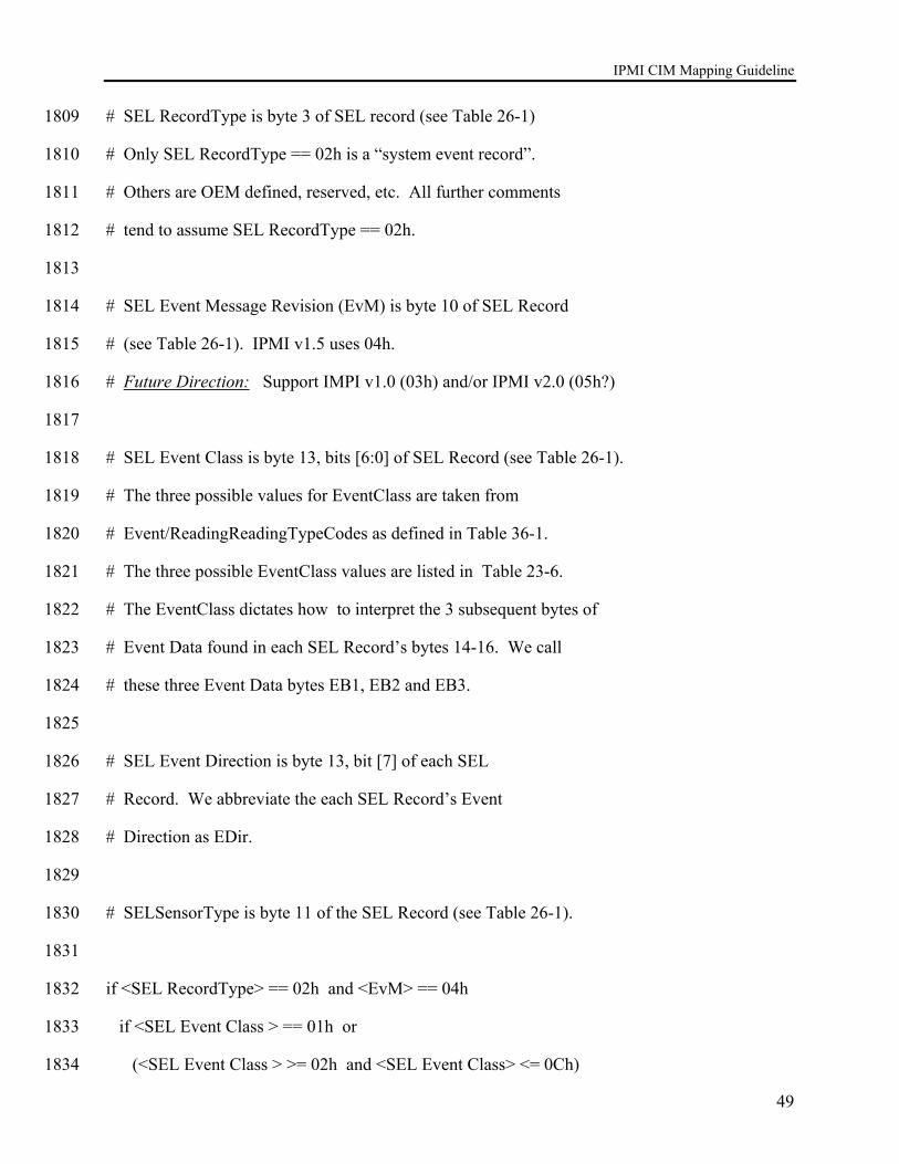
IPMI CIM Mapping Guideline
49
# SEL RecordType is byte 3 of SEL record (see Table 26-1) 1809
# Only SEL RecordType == 02h is a “system event record”. 1810
# Others are OEM defined, reserved, etc. All further comments 1811
# tend to assume SEL RecordType == 02h. 1812
1813
# SEL Event Message Revision (EvM) is byte 10 of SEL Record 1814
# (see Table 26-1). IPMI v1.5 uses 04h. 1815
# Future Direction: Support IMPI v1.0 (03h) and/or IPMI v2.0 (05h?) 1816
1817
# SEL Event Class is byte 13, bits [6:0] of SEL Record (see Table 26-1). 1818
# The three possible values for EventClass are taken from 1819
# Event/ReadingReadingTypeCodes as defined in Table 36-1. 1820
# The three possible EventClass values are listed in Table 23-6. 1821
# The EventClass dictates how to interpret the 3 subsequent bytes of 1822
# Event Data found in each SEL Record’s bytes 14-16. We call 1823
# these three Event Data bytes EB1, EB2 and EB3. 1824
1825
# SEL Event Direction is byte 13, bit [7] of each SEL 1826
# Record. We abbreviate the each SEL Record’s Event 1827
# Direction as EDir. 1828
1829
# SELSensorType is byte 11 of the SEL Record (see Table 26-1). 1830
1831
if <SEL RecordType> == 02h and <EvM> == 04h 1832
if <SEL Event Class > == 01h or 1833
(<SEL Event Class > >= 02h and <SEL Event Class> <= 0Ch) 1834

IPMI CIM Mapping Guideline
50
if <SEL EDir> == 1b 1835
strEDir = “Assert: ” 1836
else # <SEL EDir> == 0b 1837
strEDir = “Deassert: “ 1838
if <SEL EB1 [7:6]> == 11b 1839
# Use SEL SensorType and EB2 value to index into Table 36-3 1840
# to find a Sensor Specific Offset/State description string. EB2 1841
# is the Sensor-Specific Offset/State value.. 1842
strOffsetOrStateDesc = strEDir + <EStr(<EB2 into Table36-3>)> 1843
return strOffsetOrStateDesc 1844
else if <SEL EB1 [6:5]> == 11b 1845
# Use SEL SensorType and EB3 to index into Table 36-3 to find 1846
# a Sensor Specific Offset/State description string. EB3 1847
# is the Sensor-Specific Offset/State value. 1848
strOffsetOrStateDesc = strEDir + <EStr(<EB3 into Table36-3>)> 1849
return strOffsetOrStateDesc 1850
else # We’ll have to use the Generic Offset/State description strings 1851
# Use SEL EB1 [3:0] bits as a Generic Offset/State value. Use 1852
# this value, and the Event/ReadingTypeCode , to index into 1853
# Table 36-1 to find a Generic Offset/State description string. 1854
strOffsetOrStateDesc = strEDir + <EStr(<EB1[3:0] into Table36-1>)> 1855
return strOffsetOrStateDesc 1856
else # This isn’t a SEL Reading Type code that the IPMI-to-CIM 1857
# mapping supports. Skip this SEL record. It will not 1858
# be mapped to an instance of the LogRecord class. In other 1859
# words, the IPMI-to-CIM mapping ignores OEM type SEL 1860

IPMI CIM Mapping Guideline
51
# Records. 1861
4.5.2.9 CIM_LogRecord.Description 1862 (string)(<CIM_Sensor.Name>) || “: ” || (string)(EStr(CIM_Sensor.SensorType)) || “ for ” || 1863 EStr(<IPMI_SDR_EntityID>) || “ “ || (string)(<IPMI_SDR_EntityInstanceNumber>) || “; ” 1864 EStr(<SEL Generic or Sensor-Specific State Code>) 1865
See the procedure under CIM_LogRecord.Caption for a procedural description of the following 1866 term: 1867
EStr(<SEL Generic or Sensor-Specific State Code>). 1868
A SEL record’s associated CIM_Sensor instance (whether that is a NumericSensor or a Sensor 1869 instance) can be found using the SEL Record’s GeneratorID (bytes 8-9) and Sensor Number 1870 (byte 12). See Table 26-1 for details. This SEL data maps to the CIM_Sensor.DeviceID key 1871 value (as defined in the IPMI-to-CIM sensor mapping document). Once this Sensor key string is 1872 extracted from the SEL entry in question, the corresponding CIM_Sensor instance can be found. 1873
Behind the scenes, the corresponding CIM_Sensor maps to a corresponding IPMI SDR record 1874 (or either type 1 or type 2). This indirectly corresponding SDR record must also be found in 1875 order to extract the IPMI_SDR_EntityID and IPMI_SDR_EntityInstanceNumber mentioned 1876 above. 1877
We refer to the CIM_Sensor instance above because CIM_Sensor is a common base class for 1878 both NumericSensor and Sensor (as “trivially derived” for this IPMI-to-CIM mapping). 1879

IPMI CIM Mapping Guideline
52
5 IPMI Commands Mapping 1880
5.1 Introduction 1881 The IPMI Commands Mapping allows the execution of a controlled subset of available IPMI 1882 commands using a CIM_CommandService class derived from CIM_Service. 1883
5.2 Mapping Requirements 1884
5.2.1 IPMI Commands Limitations 1885 The IPMI Commands Mapping is the CIM object model to the IPMI interface mapping needed 1886 to issue and receive OEM “raw” messages to and from an embedded Baseboard Management 1887 Controller or Service Processor with IPMI compliant firmware. The class modeled in this 1888 profile is related to the IPMI BMC Messages as detailed in the IPMI Specification. 1889
This model is only intended to map the execution of IPMI OEM commands. Execution of 1890 standard IPMI commands is NOT supported by this class. Standard commands are handled 1891 internally by the Sensor and Log Mapping implementations described in this document. 1892
Also note that one instance of the CIM_CommandService class MUST be created for each IPMI 1893 capable microcontroller, in order to ensure that IPMI OEM commands destined for satellite 1894 controllers are routed correctly 1895
5.3 CIM_CommandService Mapping 1896
5.3.1 CIM_CommandService.Methods 1897
5.3.1.1 Method: ExecuteOEMCommand 1898
uint32 ExecuteOEMCommand( 1899 [IN] uint8 NetFN, 1900 [IN] uint8 CommandIdentifier, 1901 [IN] uint8 RequestPayload[], 1902 [IN ( false ), OUT] uint8 ResponseNetFN, 1903 [IN ( false ), OUT] uint8 ResponseCommandIdentifier, 1904 [IN ( false ), OUT] uint8 CompletionCode, 1905 [IN ( false ), OUT] uint8 ResponsePayload[]) 1906
MUST check for valid range of command request, as only OEM IPMI commands are 1907 supported by this method. The request is issued to the BMC only if successfully verified. 1908 Valid input parameter ranges for OEM commands are as follows: 1909
1. NetFN in range 30h through 3Fh, as described in IPMI v1.5 specification, section 5.1, 1910 table 5.1 1911
2. CommandIdentifier in range 00h through FDh., as described in IPMI v1.5 1912 specification, section 5.0 1913

IPMI CIM Mapping Guideline
53
3. When RequestPayload is assembled with NetFN, CommandIdentifier, and other 1914 request message fields, the total message length must conform to limits specified in 1915 IPMI V1.5 specification, Sections 6.13 and Appendix D. 1916
The appropriate message bytes in the resulting response are assigned to the ResponseNetFN, 1917 ResponseCommandIdentifier, CompletionCode, and ResponsePayload[] output parameters . 1918 Note that message CompletionCode output parameter MUST support all valid values 1919 described in IPMI v1.5 specification, section 5.2, table 5.2, including device-specific OEM 1920 completion codes ranges 01h – 7eh. 1921
Return value: 1922 0 – Completed with no error 1923 1 – Not Supported 1924 2 – Unspecified Error 1925 3 – Timeout 1926 4 – Failed 1927 5 – Invalid Parameter 1928 6 – NetFN Out Of Range 1929 7 – CommandIdentifier Out Of Range 1930 8 – RequestPayload too long 1931
1932
5.3.2 CIM_CommandService.Properties 1933 REQUIRED properties are properties that MUST be present. RECOMMENDED properties are 1934 properties that MAY be present. For example, there may be properties that are only filled out in 1935 special configurations of the CIM Schema. 1936
Properties that listed in the Required section in Table 5 below MUST be implemented as defined 1937 in the subsection following this table unless the Notes column for each property specifies the 1938 defining reference. 1939
Table 5 CIM_CommandService Class Properties 1940
Required Properties Notes CreationClassName Key: Name Key: SystemCreationClassName Key: SystemName Key: IANA Key:
1941 Recommended Properties Notes
Caption
Description
Started Not Defined.
StartMode Not Defined.
Status Not Defined.
InstallDate Not defined.

IPMI CIM Mapping Guideline
54
Recommended Properties Notes I
1942
The following subsections describe procedures for generating values for various properties of 1943 CIM classes required in this profile. 1944
5.3.2.1 CIM_ CommandService.SystemCreationClassName 1945 Formulate as a string: 1946
<ComputerSystem.Name of ComputerSystem instance of the one associated BMC> 1947
This is the scoping system’s CreationClassName. 1948
5.3.2.2 CIM_ CommandService.SystemName 1949 Name of the system that is hosting the CommandService 1950
5.3.2.3 CIM_CommandService.CreationClassName 1951 Fixed value of “CommandService” 1952
5.3.2.4 CIM_ CommandService.Name 1953 Name of IPMI controller to which commands will be routed, such as “Primary BMC”, “OEM 1954 satellite controller 1”, “OEM satellite controller 2”, etc. 1955
5.3.2.5 CIM_ CommandService.IANA 1956 IANA ID for microcontroller 1957
5.3.2.6 CIM_ CommandService. Caption 1958 Fixed value of “IPMI Command Service” 1959
5.3.2.7 CIM_ CommandService. Description 1960 Fixed value of “IPMI Command Service” 1961
1962

IPMI CIM Mapping Guideline
55
6 IPMI Power Control Mapping 1963
6.1 Introduction 1964 The IPMI Power Control Mapping extends the management capability of the IPMI to CIM 1965 mapping by adding the capability to manage the power state of the managed system and the 1966 BMC via IPMI represented as a CIM_PowerManagementService class. 1967
The following class diagram describes the CIM classes involved in representing IPMI power 1968 control by the CIM_PowerManagementService class. The ComputerSystem classes are shown 1969 in this diagram to illustrate the way the CIM_PowerManagementService class is associated with 1970 overall class ecosystems. This is in preparation for interoperability with forthcoming profiles 1971 from the DMTF and other standards bodies. 1972
P o w e r C o n tro lC la s s D ia g ra m
P o w e rM a n a g e m e n tS e rv ic e
E le m e n tC a p a b ilit ie s
1
1
A s s o c ia te d P o w e rM a n a g e m e n tS e rv ic e
*
1
C o m p u te rS y s te m
H o s te d S e rv ic e
P o w e rM a n a g e m e n tC a p a b ilit ie s
1
C o m p u te rS y s te m
1
*
1973
Figure 5 Class Diagram – IPMI Computer System Power Management 1974
6.2 Instance Diagrams 1975 The IPMI Computer System Power Management Mapping is the CIM object model to IPMI 1976 interface mapping needed to manage the managed or host system and the BMC power state. 1977

IPMI CIM Mapping Guideline
56
The following instance diagram represents that instantiation of 2 1978 CIM_PowerManagementService classes each responsible for representing the power control 1979 interface for either the BMC or the host system that the BMC is embedded in. The BMC and the 1980 host system are represented by instance of the CIM_ComputerSystem class. 1981
ComputerSystem
UFiT: system1
ElementCapabilities
PowerManagementCapabilities
Power Control Instance Diagram:
Monolithic Serverwith Service Processor
ComputerSystem
UFiT: sp1
PowerManagementService
AssociatedPowerManagementService
HostedService
ElementCapabilities
PowerManagementCapabilities
PowerManagementService
HostedService
AssociatedPowerManagementService
1982
Figure 6 Instance Diagram – IPMI Computer System Power Management 1983
6.3 Mapping Requirements 1984
6.4 CIM_PowerManagementService Mapping 1985
6.4.1 CIM_PowerManagementService Methods 1986
6.4.1.1 Method: PowerManagementService.SetPowerState( ) 1987
uint32 SetPowerState( uint16 PowerState, 1988 CIM_ManagedElement REF ManagedElement, 1989 datetime Time 1990 ); 1991
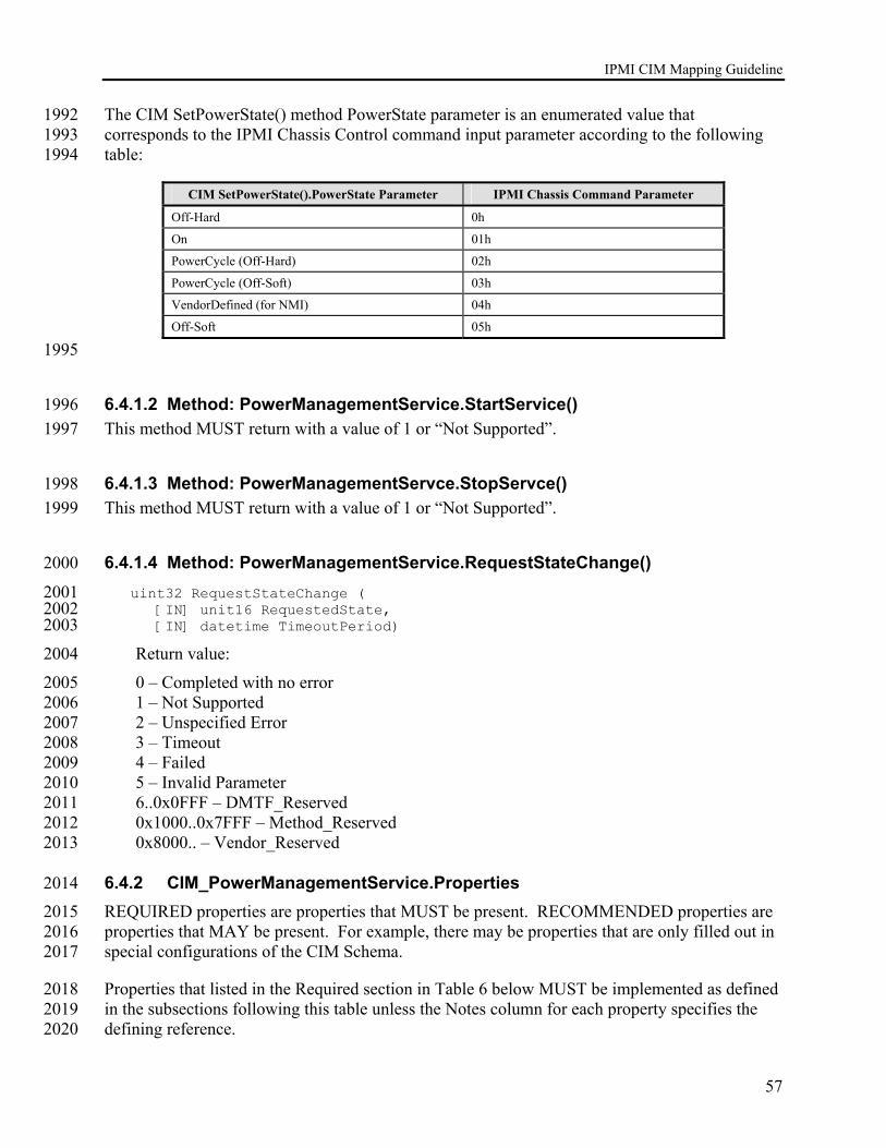
IPMI CIM Mapping Guideline
57
The CIM SetPowerState() method PowerState parameter is an enumerated value that 1992 corresponds to the IPMI Chassis Control command input parameter according to the following 1993 table: 1994
CIM SetPowerState().PowerState Parameter IPMI Chassis Command Parameter
Off-Hard 0h
On 01h
PowerCycle (Off-Hard) 02h
PowerCycle (Off-Soft) 03h
VendorDefined (for NMI) 04h
Off-Soft 05h
1995
6.4.1.2 Method: PowerManagementService.StartService() 1996 This method MUST return with a value of 1 or “Not Supported”. 1997
6.4.1.3 Method: PowerManagementServce.StopServce() 1998 This method MUST return with a value of 1 or “Not Supported”. 1999
6.4.1.4 Method: PowerManagementService.RequestStateChange() 2000
uint32 RequestStateChange ( 2001 [IN] unit16 RequestedState, 2002 [IN] datetime TimeoutPeriod) 2003
Return value: 2004
0 – Completed with no error 2005 1 – Not Supported 2006 2 – Unspecified Error 2007 3 – Timeout 2008 4 – Failed 2009 5 – Invalid Parameter 2010 6..0x0FFF – DMTF_Reserved 2011 0x1000..0x7FFF – Method_Reserved 2012 0x8000.. – Vendor_Reserved 2013
6.4.2 CIM_PowerManagementService.Properties 2014 REQUIRED properties are properties that MUST be present. RECOMMENDED properties are 2015 properties that MAY be present. For example, there may be properties that are only filled out in 2016 special configurations of the CIM Schema. 2017
Properties that listed in the Required section in Table 6 below MUST be implemented as defined 2018 in the subsections following this table unless the Notes column for each property specifies the 2019 defining reference. 2020

IPMI CIM Mapping Guideline
58
Table 6 CIM_PowerManagementService Class Properties 2021
Required Properties Notes
CreationClassName Key Name Key
2022 Recommended Properties Notes
InstallDate StatusDescriptions Caption Description ElementName
2023
The following subsections describe procedures for generating values for various properties of 2024 CIM classes required in this profile. 2025
6.4.2.1 CIM_PowerManagementService.CreationClassName 2026 Per the DMTF definition of the class property: The name of the class or the subclass used in the 2027 creation of an instance of the log for with this record is a part. This will typically be 2028 “CIM_PowerManagemetnService”. 2029
Formulate as a string: 2030
<”CIM_PowerManagementService” or the name of the subclass created> 2031
6.4.2.2 CIM_PowerManagementService.Name 2032 Fixed value of “IPMI Power Service” 2033
6.5 CIM_PowerManagementCapabilities Mapping 2034
6.5.1 CIM_PowerManagementCapabilities Methods 2035 None Defined. 2036
6.5.2 CIM_PowerManagementCapabilities Properties 2037 REQUIRED properties are properties that MUST be present. RECOMMENDED properties are 2038 properties that MAY be present according to t he guiding DMTF profiles. 2039
Properties that listed in the Required section in Table 7 below MUST be implemented as defined 2040 in the subsection following this table unless the Notes column for each property specifies the 2041 defining reference. 2042

IPMI CIM Mapping Guideline
59
Table 7 CIM_PowerManagementCapabilities Class Properties 2043
Required Properties Notes
PowerCapabilities 2044
Recommended Properties Notes
Caption Description ElementName OtherPowerCapabilitiesDescriptions
6.5.2.1 CIM_PowerManagementCapabilities.PowerCapabilities 2045 Fixed value of 3 (for the enumeration “Power State Settable”). 2046
6.6 CIM_AssociatedPowerManagementService Mapping 2047
6.6.1 CIM_AssociatedPowerManagementService Methods 2048 None Defined. 2049
6.6.2 CIM_AssociatedPowerManagementService Properties 2050 REQUIRED properties are properties that MUST be present. RECOMMENDED properties are 2051 properties that MAY be present. For example, there may be properties that are only filled out in 2052 special configurations of the CIM Schema. 2053
Properties that are listed in the Required section in Table 8 below MUST be implemented as 2054 defined in the subsections following this table unless the Notes column for each property 2055 specifies the defining reference. 2056
Table 8 CIM_AssociatedPowerManagementService Class Properties 2057
Required Properties Notes ServiceProvided REF CIM_PowerManagementService {key, *}
UserOfService REF ManagedElement {key, *}
PowerState Values { "Other", "On", "Sleep - Light", "Sleep -Deep","Off - Hard", "Hibernate (Off - Soft)", "Off - Soft", "DMTF Reserved","Vendor Specific" },
OtherPowerState
PowerOnTime
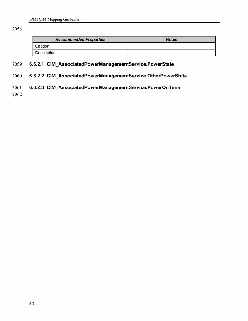
IPMI CIM Mapping Guideline
60
2058
Recommended Properties Notes Caption Description
6.6.2.1 CIM_AssociatedPowerManagementService.PowerState 2059
6.6.2.2 CIM_AssociatedPowerManagementService.OtherPowerState 2060
6.6.2.3 CIM_AssociatedPowerManagementService.PowerOnTime 2061 2062

IPMI CIM Mapping Guideline
61
7 IPMI User ID Management Mapping 2063
7.1 Introduction 2064 The IPMI User ID Management Mapping extends the management capability of the IPMI to 2065 CIM mapping by adding the capability to manage the User ID, passwords, and privileges of the 2066 BMC. 2067
The following class diagram describes the CIM classes involved in representing IPMI User ID’s, 2068 passwords, and privileges. The AdminDomain and ComputerSystem classes are shown in this 2069 diagram to illustrate the way the various classes involved in user id management are associated 2070 with overall class ecosystems. This is in preparation for interoperability with forthcoming 2071 profiles from the DMTF and other standards bodies. 2072
ComputerSystem
IPMI User IDClass Diagram
Group
OwningCollectionElement
AdminDomain
Account
MemberOfCollection
AccountOnSystem
SystemComponent AuthorizedPriviledge
AuthorizedTarget
AuthorizedTargetAuthorizedSubject
2073
Figure 7 Class Diagram – IPMI User ID Management 2074
7.2 Instance Diagrams 2075 The IPMI User ID Management Mapping is the CIM object model to IPMI interface mapping 2076 needed to manage the BMC User ID’s. The BMC and the host system are represented by 2077 instance of the CIM_ComputerSystem class. 2078
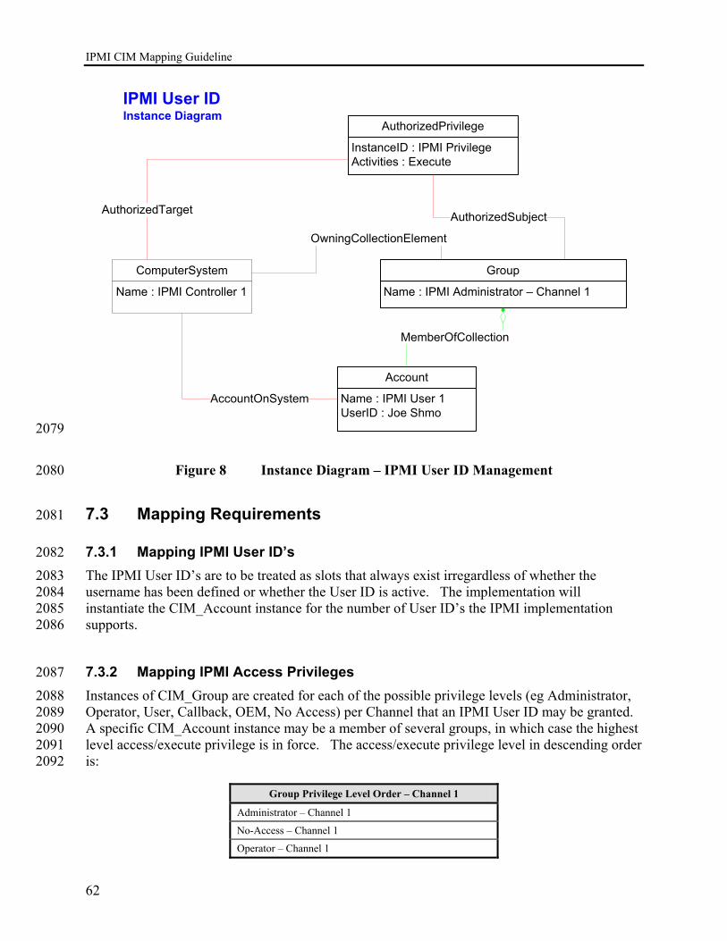
IPMI CIM Mapping Guideline
62
ComputerSystem
Name : IPMI Controller 1
IPMI User IDInstance Diagram
Group
Name : IPMI Administrator – Channel 1
OwningCollectionElement
Account
Name : IPMI User 1UserID : Joe Shmo
MemberOfCollection
AccountOnSystem
AuthorizedPrivilege
InstanceID : IPMI PrivilegeActivities : Execute
AuthorizedTarget AuthorizedSubject
2079
Figure 8 Instance Diagram – IPMI User ID Management 2080
7.3 Mapping Requirements 2081
7.3.1 Mapping IPMI User ID’s 2082 The IPMI User ID’s are to be treated as slots that always exist irregardless of whether the 2083 username has been defined or whether the User ID is active. The implementation will 2084 instantiate the CIM_Account instance for the number of User ID’s the IPMI implementation 2085 supports. 2086
7.3.2 Mapping IPMI Access Privileges 2087 Instances of CIM_Group are created for each of the possible privilege levels (eg Administrator, 2088 Operator, User, Callback, OEM, No Access) per Channel that an IPMI User ID may be granted. 2089 A specific CIM_Account instance may be a member of several groups, in which case the highest 2090 level access/execute privilege is in force. The access/execute privilege level in descending order 2091 is: 2092
Group Privilege Level Order – Channel 1
Administrator – Channel 1
No-Access – Channel 1
Operator – Channel 1

IPMI CIM Mapping Guideline
63
Group Privilege Level Order – Channel 1
User – Channel 1
Call-Back – Channel 1
OEM – Channel 1
2093
For every channel available in the implementation, a set of instances of CIM_Group 2094 corresponding to the possible proviledge levels for that channel will need to be instantiated. 2095
Example for an implementation with 2 channels: The following 12 instances of CIM_Group are 2096 required: 2097
Groups for Channel 1 Groups for Channel2
Administrator – Channel 1 Administrator – Channel 2
No-Access – Channel 1 No-Access – Channel 2
Operator – Channel 1 Operator – Channel 2
User – Channel 1 User – Channel 2
Call-Back – Channel 1 Call-Back – Channel 2
OEM – Channel 1 OEM – Channel 2
7.3.3 Modeling CIM_AuthorizedPrivilege 2098 The CIM_AuthorizedPrivilege is modeled as granting “execute” authorization to the various 2099 group it is assocated with. The implementation MUST instantiate one instance of 2100 CIM_AuthorizedPriviledge and associate each IPMI group with it. 2101
7.4 CIM_Account Mapping 2102
7.4.1 CIM_Account Methods 2103 None Defined. 2104
7.4.2 CIM_Account Properties 2105 REQUIRED properties are properties that MUST be present. RECOMMENDED properties are 2106 properties that MAY be present. For example, there may be properties that are only filled out in 2107 special configurations of the CIM Schema. 2108
Properties that listed in the Required section in Table 9 below MUST be implemented as defined 2109 in the subsections following this table unless the Notes column for each property specifies the 2110 defining reference. 2111

IPMI CIM Mapping Guideline
64
Table 9 CIM_Account Class Properties 2112
Required Properties Notes SystemCreationClassName Key SystemName Key CreationClassName Key Name Key UserID UserPassword OperationalStatus StatusDescriptions
2113
Recommended Properties Notes ObjectClass Descriptions Host LocalityName OrganizationalName OU SeeAlso UserCertificate InstallDate HealthState Caption Description ElementName
2114
The following subsections describe procedures for generating values for various properties of 2115 CIM classes required in this profile. 2116
7.4.2.1 CIM_Account.SystemCreationClassName 2117 Per the DMTF definition of the class property: The scoping System's CreationClassName. In all 2118 cases this will be the class “CIM_ComputerSystem”. 2119
Formulate as a string: 2120
<”CIM_ComputerSystem”> 2121
7.4.2.2 CIM_Account.SystemName 2122 Formulate as a string: 2123

IPMI CIM Mapping Guideline
65
<ComputerSystem.Name of ComputerSystem instance of the one associated BMC> 2124
The System instance that represents the associated management controller has a Name property. 2125 This be found and then copied in here. Since there is but one instance of a management 2126 controller for most IPMI-compliant devices/systems, this is often quite easy to do. 2127
7.4.2.3 CIM_Account.CreationClassName 2128 Per the DMTF definition of the class property: The name of the class or the subclass used in the 2129 creation of an instance of the log for with this record is a part. This will typically be 2130 “CIM_Account”. 2131
Formulate as a string: 2132
<”CIM_Account” or the name of the subclass created> 2133
7.4.2.4 CIM_Account.Name 2134 IPMI User ID slot number. 2135
Formulate as a string: 2136
”IPMI User” || <IPMI User ID> 2137
Where the IPMI User ID is a number from 1 to N where N is the number of User ID’s supported 2138 by the IPMI implementation. An instance of CIM_Account MUST be instantiated for every 2139 possible used, including those cases where the UserName is Null. 2140
7.4.2.5 CIM_Account.UserID 2141 IPMI User Name. 2142
Formulate as a string: 2143
<IPMI User Name> 2144
The IPMI User Name is retrieved from the IPMI command GetUsername(). 2145
7.4.2.6 CIM_Account.UserPassword 2146 IPMI Password. 2147
This is always Null for read operations. 2148
7.4.2.7 CIM_Account.OperationalStatus 2149 2150

IPMI CIM Mapping Guideline
66
7.4.2.8 CIM_Account.StatusDescriptions 2151
7.5 CIM_Group Mapping 2152
7.5.1 CIM_Group Methods 2153 None Defined. 2154
7.5.2 CIM_Group Properties 2155 REQUIRED properties are properties that MUST be present. RECOMMENDED properties are 2156 properties that MAY be present according to t he guiding DMTF profiles. 2157
Properties that listed in the Required section in Table 10 below MUST be implemented as 2158 defined in the subsection following this table unless the Notes column for each property specifies 2159 the defining reference. 2160
Table 10 CIM_Group Class Properties 2161
Required Properties Notes CreationClassName Key Name Key
2162
Recommended Properties Notes BusinessCategory CommonName Caption Description ElementName
7.5.2.1 CIM_Group.CreationClassName 2163 Per the DMTF definition of the class property: The name of the class or the subclass used in the 2164 creation of an instance of the log for with this record is a part. This will typically be 2165 “CIM_Group”. 2166
Formulate as a string: 2167
<”CIM_Group” or the name of the subclass created> 2168
7.5.2.2 CIM_Group.Name 2169 Instances of CIM_Group MUST be created for each of the following IPMI user level privileges. 2170
Formulate as a string the following IPMI user level privileges: 2171
IPMI Administrator 2172

IPMI CIM Mapping Guideline
67
IPMI Operator 2173
IPMI User 2174
IPMI Callback 2175
IPMI OEM 2176
IPMI No Access 2177
7.6 CIM_AuthorizedPrivilege Mapping 2178
7.6.1 CIM_AuthorizedPrivilege Methods 2179 None Defined. 2180
7.6.2 CIM_AuthorizedPrivilege Properties 2181 REQUIRED properties are properties that MUST be present. RECOMMENDED properties are 2182 properties that MAY be present. For example, there may be properties that are only filled out in 2183 special configurations of the CIM Schema. 2184
Properties that listed in the Required section in Table 11 below MUST be implemented as 2185 defined in the subsections following this table unless the Notes column for each property 2186 specifies the defining reference. 2187
Table 11 CIM_AuthorizedPrivilege Class Properties 2188
Required Properties Notes
InstanceID Key PrivilegeGranted Boolean Activities ElementName
2189 Recommended Properties Notes
ActivityQualifiers QualifierFormats Caption Description
7.6.2.1 CIM_AuthorizedPrivilege.InstanceID 2190 Formulate as a string: 2191
“IPMI Privilege” 2192

IPMI CIM Mapping Guideline
68
7.6.2.2 CIM_AuthorizedPrvilege.PrivilegeGranted 2193 Formulate as a Boolean: 2194
Yes 2195
7.6.2.3 CIM_AuthorizedPrivilege.Activities 2196 Formulate as an integer enumeration: 2197
7 (Enumeration = “Execute”) 2198
7.6.2.4 CIM_AuthorizedPrivilege.ElementName 2199 Formulate as a string: 2200
“IPMI Execute Privilege” 2201
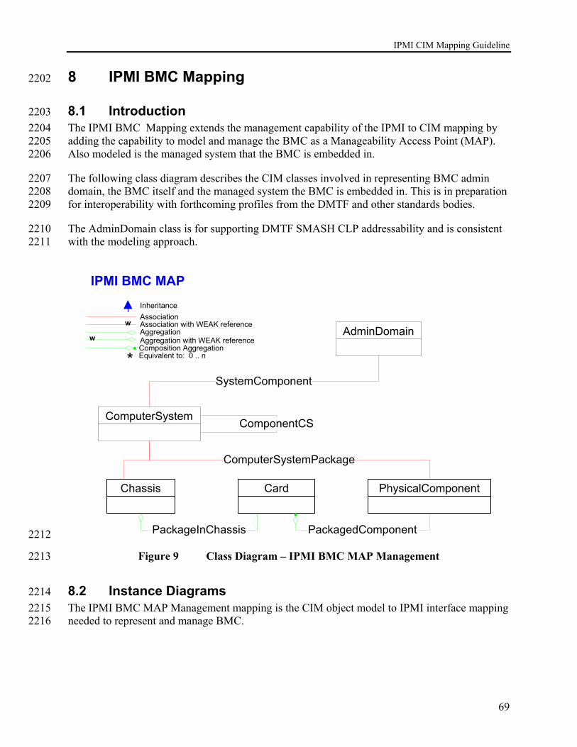
IPMI CIM Mapping Guideline
69
8 IPMI BMC Mapping 2202
8.1 Introduction 2203 The IPMI BMC Mapping extends the management capability of the IPMI to CIM mapping by 2204 adding the capability to model and manage the BMC as a Manageability Access Point (MAP). 2205 Also modeled is the managed system that the BMC is embedded in. 2206
The following class diagram describes the CIM classes involved in representing BMC admin 2207 domain, the BMC itself and the managed system the BMC is embedded in. This is in preparation 2208 for interoperability with forthcoming profiles from the DMTF and other standards bodies. 2209
The AdminDomain class is for supporting DMTF SMASH CLP addressability and is consistent 2210 with the modeling approach. 2211
IPMI BMC MAP
ComputerSystem
Association
AggregationAssociation with WEAK reference
Inheritance
Aggregation with WEAK reference
w
w
* Equivalent to: 0 .. nComposition Aggregation
Chassis
PackageInChassis
ComputerSystemPackage
Card
PackagedComponent
AdminDomain
SystemComponent
ComponentCS
PhysicalComponent
2212
Figure 9 Class Diagram – IPMI BMC MAP Management 2213
8.2 Instance Diagrams 2214 The IPMI BMC MAP Management mapping is the CIM object model to IPMI interface mapping 2215 needed to represent and manage BMC. 2216

IPMI CIM Mapping Guideline
70
IPMI BMC MAP Instance
Name : Host SystemRole : Managed System
ComputerSystem
Association
AggregationAssociation with WEAK reference
Inheritance
Aggregation with WEAK reference
w
w
* Equivalent to: 0 .. nComposition Aggregation
ComputerSystem
Name : IPMI Controller 1Role : HW Management Controller
Tag : Host System ChassisChassisPackageType : Main System Chassis
ChassisTag : IPMI BMC
Physical Component
ComputerSystemPackage
PackageInChassis
ComputerSystemPackage
Tag : MotherboardPackageType : Module/Card
Card PackagedComponent
Name : MAPRole : MAP Addressing Root
AdminDomain
SystemComponent
ComponentCS
2217
Figure 10 Instance Diagram – IPMI BMC MAP Management 2218
8.3 Mapping Requirements 2219 The implementation MUST instantiate a single instance of CIM_AdminDomain in the 2220 implementation namespace and MUST instantiate two (2) instances of CIM_ComputerSystem. 2221 The first instance of CIM_ComputerSystem is to represent the BMC and the second instance is 2222 to represent the host or managed system. 2223 2224 Physical classes such as CIM_Chassis and CIM_Card SHOULD be instantiated if the 2225 implementation has FRU and/or other host system inventory data, including the host system 2226 name. 2227

IPMI CIM Mapping Guideline
71
8.4 CIM_AdminDomain Mapping 2228
8.4.1 CIM_AdminDomain Methods 2229
8.4.1.1 Method: AdminDomain.RequestStateChange() 2230
uint32 RequestStateChange ( 2231 [IN] unit16 RequestedState, 2232 [IN] datetime TimeoutPeriod) 2233
Return value: 2234
0 – Completed with no error 2235 1 – Not Supported 2236 2 – Unspecified Error 2237 3 – Timeout 2238 4 – Failed 2239 5 – Invalid Parameter 2240 6..0x0FFF – DMTF_Reserved 2241 0x1000..0x7FFF – Method_Reserved 2242 0x8000.. – Vendor_Reserved 2243
8.4.2 CIM_AdminDomain.Properties 2244 REQUIRED properties are properties that MUST be present. RECOMMENDED properties are 2245 properties that MAY be present. For example, there may be properties that are only filled out in 2246 special configurations of the CIM Schema. 2247
Properties that are listed in the Required section in Table 6 below MUST be implemented as 2248 defined in the subsections following this table unless the Notes column for each property 2249 specifies the defining reference. 2250
Table 12 CIM_AdminDomain Class Properties 2251
Required Properties Notes
CreationClassName Key Name Key
2252 Recommended Properties Notes
NameFormat PrimaryOwnerName PrimaryOwnerContact Roles EnabledState OtherEnabledState RequestedState EnabledDefault
IPMI CIM Mapping Guideline
72
Recommended Properties Notes
TimeOfLastStateChange InstallDate OperationalStatus StatusDescriptions HealthState Caption Description ElementName
2253
The following subsections describe procedures for generating values for various properties of 2254 CIM classes required in this profile. 2255
8.4.2.1 CIM_AdminDomain.CreationClassName 2256 Per the DMTF definition of the class property: The name of the class or the subclass used in the 2257 creation of an instance of the log for with this record is a part. This will typically be 2258 “CIM_AdminDomain”. 2259
Formulate as a string: 2260
<”CIM_AdminDomain” or the name of the subclass created> 2261
8.4.2.2 CIM_AdminDomain.Name 2262 Fixed value of “MAP” 2263
8.5 CIM_ComputerSystem Mapping 2264
8.5.1 CIM_ComputerSystem Methods 2265
8.5.1.1 Method: ComputerSystem.RequestStateChange() 2266
uint32 RequestStateChange ( 2267 [IN] unit16 RequestedState, 2268 [IN] datetime TimeoutPeriod) 2269
Return value: 2270
0 – Completed with no error 2271 1 – Not Supported 2272 2 – Unspecified Error 2273 3 – Timeout 2274 4 – Failed 2275 5 – Invalid Parameter 2276

IPMI CIM Mapping Guideline
73
6..0x0FFF – DMTF_Reserved 2277 0x1000..0x7FFF – Method_Reserved 2278 0x8000.. – Vendor_Reserved 2279
8.5.2 CIM_ComputerSystem Properties 2280 REQUIRED properties are properties that MUST be present. RECOMMENDED properties are 2281 properties that MAY be present according to t he guiding DMTF profiles. 2282
Properties that listed in the Required section in Table 7 below MUST be implemented as defined 2283 in the subsection following this table unless the Notes column for each property specifies the 2284 defining reference. 2285
Table 13 CIM_ComputerSystem Class Properties 2286
Required Properties Notes
Name KEY
CreationClassName KEY
Dedicated
Roles
EnabledState
HealthState
OperationalStatus 2287
Recommended Properties Notes
NameFormat OtherIdentifyingInfo IdentifyingDescriptions OtherDedcatedDescriptions ResetCapability PrimaryOwnerName PrimaryOwnerContact
RequestedState
OtherEnabledState EnabledDefault TimeOfLastStateChange InstallDate StatusDescriptions Caption Description ElementName
2288

IPMI CIM Mapping Guideline
74
The following sections may describe the values for two instances of CIM_ComputerSystem. 2289 The values for the instance of CIM_ComputerSystem that represent the BMC are labeled with a 2290 “BMC:” and the value definitions for the instance that represent the managed system are labeled 2291 “Host:”. 2292
8.5.2.1 CIM_ComputerSystem.Name 2293 BMC: 2294
Concatenation of “IPMI Controller” and BMC device ID (Get Device ID response byte 2) 2295
Formulate as a string: 2296
<”IPMI Controller” || string (Get Device ID response byte 2)> 2297
Example Value: “IPMI Controller 32” 2298
Host: 2299
The goal for the value of the Name property for the instance of CIM_ComputerSystem 2300 representing the IPMI host or managed system is to provide a correlatable identifier that can be 2301 used by applications to correlate representations from different manageability access points. At 2302 present, due to various versions of IPMI being available in the field and a general lack of 2303 consensus in the industry as to what correlatable identifier should be predominant, the value 2304 formulation presented here is an attempt to define a formulation that can be generated across 2305 various situations. 2306
The general format of the Name property shall be: 2307
< (NameValue) || “:” || 2308
string (GUID as retrieved from Get System GUID IPMI Command)> 2309
Where NameValue is generated in the following fashion: 2310
IF the implementation resides in-band in the OS resident on the system containing the BMC, the 2311 implementation should use the value of the Name property in the instance of 2312 CIM_ComputerSystem generated by OS instrumentation and representing the managed system 2313 for NameValue. 2314
Else IF the MultiRecord Area is available in the system FRU and the Management Access 2315 Record (Type 0x03) Sub-Record Type (0x02) System Name string is populated, use this value 2316 for NameValue. 2317
Else IF the IPMI interface supports the IPMI 2.0 command Get System Info, use the value 2318 returned in the System Name parameter for NameValue. 2319
Else use the following value for NameValue: 2320
< “Unknown” || “.” || “IPMI BMC Device ID” || “.” || 2321
IPMI CIM Mapping Guideline
75
string (Device ID as retrieved from the Get Device ID IPMI command)> 2322
8.5.2.2 CIM_ComputerSystem.CreationClassName 2323 Per the DMTF definition of the class property: The name of the class or the subclass used in the 2324 creation of an instance of the log for with this record is a part. This will typically be 2325 “CIM_ComputerSystem”. 2326
Formulate as a string: 2327
<”CIM_ComputerSystem” or the name of the subclass created> 2328
8.5.2.3 CIM_ComputerSystem.Dedicated 2329 BMC: 2330
For the instance of CIM_ComputerSystem representing the IPMI BMC: 2331
This is a fixed value: 14 (enumerated as “Management Controller”) 2332
Host: 2333
The value of the Dedicated property for the managed system is left up to the implementation to 2334 select the appropriate value from the enumeration value/value maps defined in the 2335 CIM_ComputerSystem MOF. However, the when implementation is representing a general 2336 purpose server it should use the value of: 2337
0 (enumerated as “Not Dedicated”) 2338
8.5.2.4 CIM_ComputerSystem.Roles 2339 This property is writeable and may be changed by the user/application. 2340
BMC: 2341
For the instance of CIM_ComputerSystem representing the IPMI BMC: 2342
The initial value: “Hardware Management Controller” 2343
Host: 2344
For the instance of CIM_ComputerSystem representing the managed system: 2345
The initial value: “Managed System” 2346

IPMI CIM Mapping Guideline
76
8.5.2.5 CIM_ComputerSystem.EnabledState 2347
8.5.2.6 CIM_ComputerSystem.HealthState 2348
8.5.2.7 CIM_ComputerSystem.OperationalStatus 2349
8.5.2.8 CIM_ComputerSystem.NameFormat 2350 Format of the Name string generated by this mapping: 2351
This is a fixed value of “Other” 2352
8.5.2.9 CIM_ComputerSystem.ElementName 2353 BMC: 2354
Concatenation of “IPMI Controller” and BMC device ID (Get Device ID response byte 2) 2355
Formulate as a string: 2356
<”IPMI Controller” || string (Get Device ID response byte 2)> 2357
Example Value: “IPMI Controller 32” 2358
Host: 2359
The goal for the value of the Name property for the instance of CIM_ComputerSystem 2360 representing the IPMI host or managed system is to provide a correlatable identifier that can be 2361 used by applications to correlate representations from different manageability access points. At 2362 present, due to various versions of IPMI being available in the field and a general lack of 2363 consensus in the industry as to what correlatable identifier should be predominant, the value 2364 formulation presented here is an attempt to define a formulation that can be generated across 2365 various situations. 2366
The general format of the Name property shall be: 2367
< (NameValue) || “:” || 2368
string (GUID as retrieved from Get System GUID IPMI Command)> 2369
Where NameValue is generated in the following fashion: 2370
IF the implementation resides in-band in the OS resident on the system containing the BMC, the 2371 implementation should use the value of the Name property in the instance of 2372 CIM_ComputerSystem generated by OS instrumentation and representing the managed system 2373 for NameValue. 2374
Else IF the MultiRecord Area is available in the system FRU and the Management Access 2375 Record (Type 0x03) Sub-Record Type (0x02) System Name string is populated, use this value 2376 for NameValue. 2377
IPMI CIM Mapping Guideline
77
Else IF the IPMI interface supports the IPMI 2.0 command Get System Info, use the value 2378 returned in the System Name parameter for NameValue. 2379
Else use the following value for NameValue: 2380
< “Unknown” || “.” || “IPMI BMC Device ID” || “.” || 2381
string (Device ID as retrieved from the Get Device ID IPMI command)> 2382
8.5.2.10 CIM_ComputerSystem.IdentifyingDescriptions 2383 2384
Fixed value as: “Manufacturer ID-Product ID” 2385
8.5.2.11 CIM_ComputerSystem.OtherIdentifyingInfo 2386 Concatenation of BMC Manufacturer ID (Get Device ID response byte 8-10) and BMC Product 2387 ID(Get Device ID response byte 11-12) 2388
Formulate as a string: 2389
< string (Get Device ID response byte 8-10) || 2390
string (Get Device ID response byte 11-12) > 2391
Example: 2392
11102-12345 2393
8.5.2.12 CIM_ComputerSystem.Caption 2394 Concatenation of “BMC ” and its device ID (Get Device ID response byte 2) 2395
Formulate as a string: 2396
< “BMC “ || string (Get Device ID response byte 2) > 2397
Example: 2398
“BMC 32” 2399
8.5.2.13 CIM_ComputerSystem.Description 2400 Concatenation of BMC device ID (Get Device ID response byte 2), IPMI version (Get Device ID 2401 response byte 6), BMC firmware revision (Get Device ID response byte 4-5), BMC auxiliary 2402 firmware revision (Get Device ID response byte 13-16) 2403
Formulate as a string: 2404
IPMI CIM Mapping Guideline
78
< “BMC “ || string (Get Device ID response byte 2) || “ – IPMI v” || 2405
string (Get Device ID response byte 6) || “ – fw v” || 2406
string (Get Device ID response byte 4-5) || “.” || 2407
string (Get Device ID response byte 13-16) > 2408
Exmaple: 2409
“BMC 32 - IPMI v1.5 - fw v0.30.0.0.0.0” 2410

IPMI CIM Mapping Guideline
79
9 IPMI Versioning Mapping 2411
9.1 Introduction 2412 The IPMI Versioning Mapping extends the management capability of the IPMI to CIM mapping 2413 by adding the capability to model the version of the mapping being implemented 2414
The following class diagram describes the CIM classes involved in representing the IPMI to CIM 2415 mapping version being implemented. The use of the CIM_RegisteredProfile class to represent 2416 the version of the IPMI to CIM “Mapping” is not completely aligned with the description of the 2417 class. However, due to the lack of another class suitable for representing the Mapping version 2418 information, the mapping will reuse the CIM_RegisteredProfile class. The implementation 2419 should instantiate the instance of CIM_RegisteredProfile in the implementation namespace so as 2420 to avoid having to support cross namespace associations. 2421
AdminDomain
RegisteredProfile
Association
AggregationAssociation with WEAK reference
Inheritance
Aggregation with WEAK reference
w
w
* Equivalent to: 0 .. nComposition Aggregation
{E} Experimental Class or Property{D} Deprecated Class or Property
IPMI Versioning Class Diagram
ComputerSystem
ElementConformsToProfile
ElementConformsToProfile
2422
Figure 11 Class Diagram – IPMI Versioning 2423
9.2 Instance Diagrams 2424 The IPMI Versioning mapping is the CIM object model representation of the version of the IPMI 2425 to CIM mapping implemented. 2426
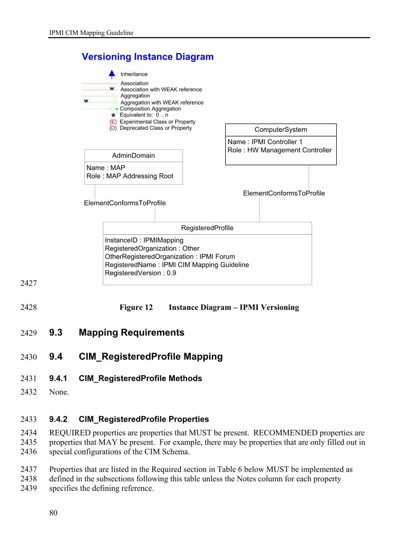
IPMI CIM Mapping Guideline
80
AdminDomain
Name : MAPRole : MAP Addressing Root
InstanceID : IPMIMappingRegisteredOrganization : OtherOtherRegisteredOrganization : IPMI Forum RegisteredName : IPMI CIM Mapping GuidelineRegisteredVersion : 0.9
RegisteredProfile
Association
AggregationAssociation with WEAK reference
Inheritance
Aggregation with WEAK reference
w
w
* Equivalent to: 0 .. nComposition Aggregation
{E} Experimental Class or Property{D} Deprecated Class or Property
Versioning Instance Diagram
ComputerSystem
Name : IPMI Controller 1Role : HW Management Controller
ElementConformsToProfileElementConformsToProfile
2427
Figure 12 Instance Diagram – IPMI Versioning 2428
9.3 Mapping Requirements 2429
9.4 CIM_RegisteredProfile Mapping 2430
9.4.1 CIM_RegisteredProfile Methods 2431 None. 2432
9.4.2 CIM_RegisteredProfile Properties 2433 REQUIRED properties are properties that MUST be present. RECOMMENDED properties are 2434 properties that MAY be present. For example, there may be properties that are only filled out in 2435 special configurations of the CIM Schema. 2436
Properties that are listed in the Required section in Table 6 below MUST be implemented as 2437 defined in the subsections following this table unless the Notes column for each property 2438 specifies the defining reference. 2439
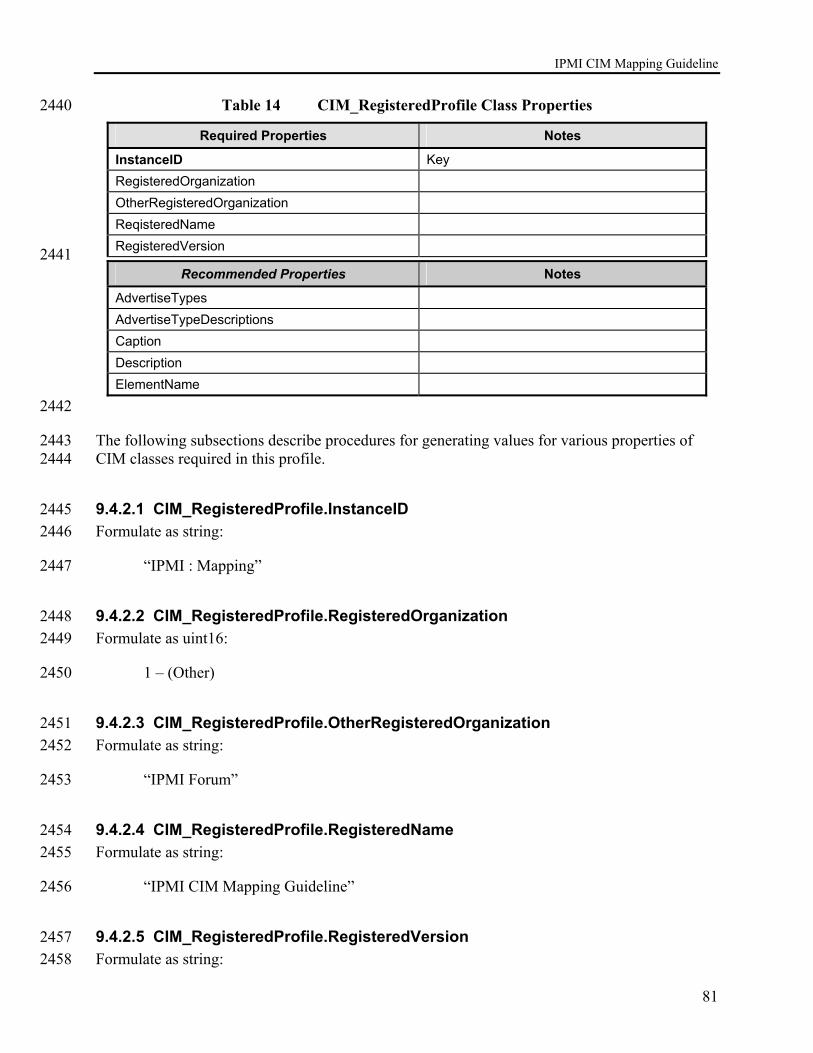
IPMI CIM Mapping Guideline
81
Table 14 CIM_RegisteredProfile Class Properties 2440
Required Properties Notes
InstanceID Key RegisteredOrganization OtherRegisteredOrganization ReqisteredName RegisteredVersion
2441 Recommended Properties Notes
AdvertiseTypes AdvertiseTypeDescriptions Caption Description ElementName
2442
The following subsections describe procedures for generating values for various properties of 2443 CIM classes required in this profile. 2444
9.4.2.1 CIM_RegisteredProfile.InstanceID 2445 Formulate as string: 2446
“IPMI : Mapping” 2447
9.4.2.2 CIM_RegisteredProfile.RegisteredOrganization 2448 Formulate as uint16: 2449
1 – (Other) 2450
9.4.2.3 CIM_RegisteredProfile.OtherRegisteredOrganization 2451 Formulate as string: 2452
“IPMI Forum” 2453
9.4.2.4 CIM_RegisteredProfile.RegisteredName 2454 Formulate as string: 2455
“IPMI CIM Mapping Guideline” 2456
9.4.2.5 CIM_RegisteredProfile.RegisteredVersion 2457 Formulate as string: 2458

IPMI CIM Mapping Guideline
82
“Version” || <version of this IPMI CIM Mapping Guideline> 2459
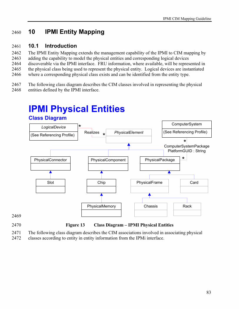
IPMI CIM Mapping Guideline
83
10 IPMI Entity Mapping 2460
10.1 Introduction 2461 The IPMI Entity Mapping extends the management capability of the IPMI to CIM mapping by 2462 adding the capability to model the physical entities and corresponding logical devices 2463 discoverable via the IPMI interface. FRU information, where available, will be represented in 2464 the physical class being used to represent the physical entity. Logical devices are instantiated 2465 where a corresponding physical class exists and can be identified from the entity type. 2466
The following class diagram describes the CIM classes involved in representing the physical 2467 entities defined by the IPMI interface. 2468
IPMI Physical EntitiesClass Diagram
PhysicalPackage
Realizes
ComputerSystem
(See Referencing Profile)LogicalDevice
(See Referencing Profile)
ComputerSystemPackagePlatformGUID : String
*
**
*
CardPhysicalFrame
Chassis Rack
Chip
PhysicalComponent
PhysicalElement
PhysicalMemory
PhysicalConnector
Slot
2469
Figure 13 Class Diagram – IPMI Physical Entities 2470 The following class diagram describes the CIM associations involved in associating physical 2471 classes according to entity in entity information from the IPMi interface. 2472
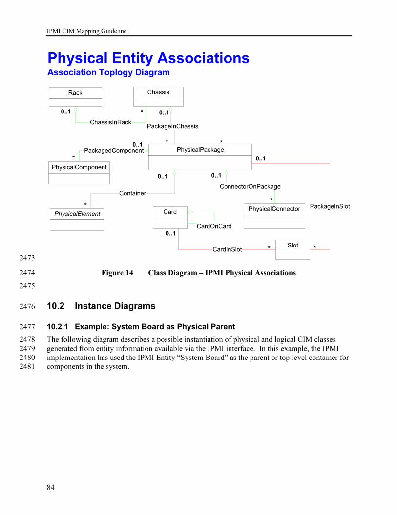
IPMI CIM Mapping Guideline
84
Chassis
ChassisInRack
0..1 *
Rack
PhysicalPackage
0..1
*
PackageInChassis
PhysicalConnector
ConnectorOnPackage
0..1
*
PhysicalComponent
PackagedComponent0..1
*
0..1
PhysicalElement
Container
*Card
CardOnCard
CardInSlot
0..1
* Slot
PackageInSlot
0..1
*
*
Physical Entity AssociationsAssociation Toplogy Diagram
2473
Figure 14 Class Diagram – IPMI Physical Associations 2474 2475
10.2 Instance Diagrams 2476
10.2.1 Example: System Board as Physical Parent 2477 The following diagram describes a possible instantiation of physical and logical CIM classes 2478 generated from entity information available via the IPMI interface. In this example, the IPMI 2479 implementation has used the IPMI Entity “System Board” as the parent or top level container for 2480 components in the system. 2481
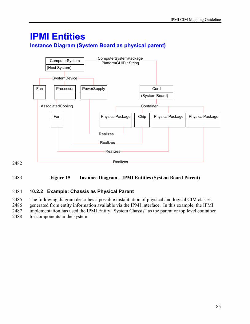
IPMI CIM Mapping Guideline
85
IPMI EntitiesInstance Diagram (System Board as physical parent)
PhysicalPackage
ComputerSystem
(Host System)
ComputerSystemPackagePlatformGUID : String
Card
(System Board)
Chip
ProcessorFan PowerSupply
SystemDevice
Fan
AssociatedCooling
Realizes
PhysicalPackage PhysicalPackage
Container
Realizes
Realizes
Realizes 2482
Figure 15 Instance Diagram – IPMI Entities (System Board Parent) 2483
10.2.2 Example: Chassis as Physical Parent 2484 The following diagram describes a possible instantiation of physical and logical CIM classes 2485 generated from entity information available via the IPMI interface. In this example, the IPMI 2486 implementation has used the IPMI Entity “System Chassis” as the parent or top level container 2487 for components in the system. 2488

IPMI CIM Mapping Guideline
86
IPMI EntitiesInstance Diagram (Chassis as physical parent)
PhysicalPackage
ComputerSystem
(See Referencing Profile)
ComputerSystemPackagePlatformGUID : String
Card
Chassis
Chip
ProcessorFan PowerSupply
SystemDevice
Fan
AssociatedCooling Realizes
PhysicalPackage
PhysicalPackage
Container
Realizes
Realizes
Realizes
PackageInChassis
2489
Figure 16 Instance Diagram – IPMI Entities (Chassis Parent) 2490 2491
10.3 Mapping Requirements 2492 Mapping IPMI entities and containers to CIM classes involves instantiating physical CIM classes 2493 to model hierarchical relationships and to provide data structures for FRU information. In many 2494 cases, CIM logical device classes also need to be instantiated to provide actual manageability of 2495 the components being modeled in addition to providing representations that are meaningful to 2496 consumers. Examples are the modeling of a Fan entity using both CIM_PhysicalPackage and 2497 CIM_Fan classes for the case where both physical and logical are instantiated and the modeling 2498 of a Disk Drive Bay where only the CIM_PhysicalPackage physical class is used. 2499 2500
10.3.1 Mapping Entity ID’s to CIM Classes 2501 The following table defines the mapping from the IPMI Entity IDs (Table 37.13 IPMI 1.5 2502 Specification) to physical and logical CIM classes. Note that some entity ID types do not have 2503 corresponding logical device types in CIM. Additionally, the IPMI entity id’s representing 2504 software are mapped to CIM_SoftwareIdentity, which is not a physical class. 2505 2506
IPMI Entity CIM Physical Class CIM Logical Device
Processor (03h) CIM_Chip CIM_Processor

IPMI CIM Mapping Guideline
87
IPMI Entity CIM Physical Class CIM Logical Device
Disk or disk bay (04h) CIM_PhysicalPackage CIM_DiskDrive
Peripheral bay (05h) CIM_PhysicalPackage
System management module (06h) CIM_PhysicalPackage CIM_ComputerSystem (BMC)
System board (07h) CIM_Card CIM_ComputerSystem (Main System)
Memory module (08h) CIM_PhysicalPackage CIM_Memory
Processor module (09h) CIM_PhysicalPackage CIM_Processor
Powey supply (0Ah) CIM_PhysicalPackage CIM_PowerSupply
Add-in card (0Bh) CIM_Card CIM_ComputerSystem
Front panel board (0Ch) CIM_Card
Back panel board (0Dh) CIM_Card
Power system board (0Eh) CIM_Card CIM_PowerSupply
Drive backplane (0Fh) CIM_Card
System internal expansion board (10h) CIM_Card CIM_ComputerSystem
Other system board (11h) CIM_Card
Processor board (12h) CIM_Card CIM_Processor
Power unit/power domain (13h) CIM_PhysicalPackage CIM_PowerSupply
Power module/DC-to-DC converter (14h)
CIM_PhysicalPackage CIM_PowerSupply
Power management/power distribution board (15h)
CIM_Card CIM_PowerSupply
Chassis back panel board (16h) CIM_Card
System chassis (17h) CIM_Chassis CIM_ComputerSystem (Managed System)
Sub-chassis (18h) CIM_Chassis
Other chassis board (19h) CIM_Card
Disk drive bay (1Ah) CIM_PhysicalPackage
Peripheral bay (1BH) CIM_PhysicalPackage
Device bay (1Ch) CIM_PhysicalPackage
Fan/cooling unit (1Eh) CIM_PhysicalPackage CIM_Fan
Cable/interconnect (1Fh) CIM_PhysicalPackage
Memory device (20h) CIM_PhysicalPackage CIM_Memory
System management software (21h) CIM_SoftwareIdentity
System firmware (22h) CIM_SoftwareIdentity
Operating system (23h) CIM_SoftwareIdentity
System bus (24h) CIM_PhysicalPackage
Group (25h)
Remote management card (26h) CIM_Card CIM_ComputerSystem
External environment (27h)
Battery (28h) CIM_PhysicalPackage CIM_Battery
Processing blade (29h) CIM_PhysicalPackage CIM_ComputerSystem
Connectivity switch (2Ah) CIM_PhysicalPackage CIM_ComputerSystem
Processor/memory module (2Bh) CIM_PhysicalPackage CIM_ComputerSystem
I/O module (2Ch) CIM_PhysicalPackage CIM_ComputerSystem
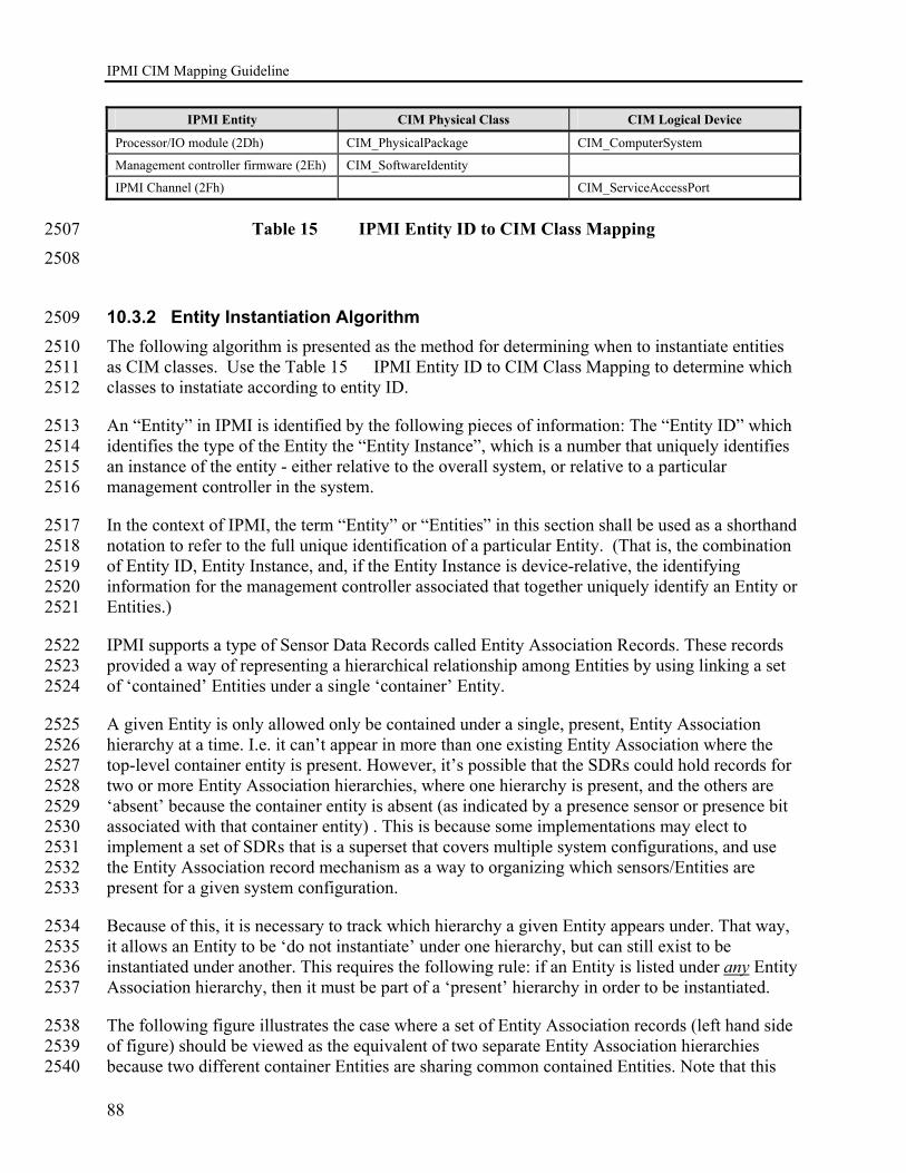
IPMI CIM Mapping Guideline
88
IPMI Entity CIM Physical Class CIM Logical Device
Processor/IO module (2Dh) CIM_PhysicalPackage CIM_ComputerSystem
Management controller firmware (2Eh) CIM_SoftwareIdentity
IPMI Channel (2Fh) CIM_ServiceAccessPort
Table 15 IPMI Entity ID to CIM Class Mapping 2507 2508
10.3.2 Entity Instantiation Algorithm 2509 The following algorithm is presented as the method for determining when to instantiate entities 2510 as CIM classes. Use the Table 15 IPMI Entity ID to CIM Class Mapping to determine which 2511 classes to instatiate according to entity ID. 2512
An “Entity” in IPMI is identified by the following pieces of information: The “Entity ID” which 2513 identifies the type of the Entity the “Entity Instance”, which is a number that uniquely identifies 2514 an instance of the entity - either relative to the overall system, or relative to a particular 2515 management controller in the system. 2516
In the context of IPMI, the term “Entity” or “Entities” in this section shall be used as a shorthand 2517 notation to refer to the full unique identification of a particular Entity. (That is, the combination 2518 of Entity ID, Entity Instance, and, if the Entity Instance is device-relative, the identifying 2519 information for the management controller associated that together uniquely identify an Entity or 2520 Entities.) 2521
IPMI supports a type of Sensor Data Records called Entity Association Records. These records 2522 provided a way of representing a hierarchical relationship among Entities by using linking a set 2523 of ‘contained’ Entities under a single ‘container’ Entity. 2524
A given Entity is only allowed only be contained under a single, present, Entity Association 2525 hierarchy at a time. I.e. it can’t appear in more than one existing Entity Association where the 2526 top-level container entity is present. However, it’s possible that the SDRs could hold records for 2527 two or more Entity Association hierarchies, where one hierarchy is present, and the others are 2528 ‘absent’ because the container entity is absent (as indicated by a presence sensor or presence bit 2529 associated with that container entity) . This is because some implementations may elect to 2530 implement a set of SDRs that is a superset that covers multiple system configurations, and use 2531 the Entity Association record mechanism as a way to organizing which sensors/Entities are 2532 present for a given system configuration. 2533
Because of this, it is necessary to track which hierarchy a given Entity appears under. That way, 2534 it allows an Entity to be ‘do not instantiate’ under one hierarchy, but can still exist to be 2535 instantiated under another. This requires the following rule: if an Entity is listed under any Entity 2536 Association hierarchy, then it must be part of a ‘present’ hierarchy in order to be instantiated. 2537
The following figure illustrates the case where a set of Entity Association records (left hand side 2538 of figure) should be viewed as the equivalent of two separate Entity Association hierarchies 2539 because two different container Entities are sharing common contained Entities. Note that this 2540
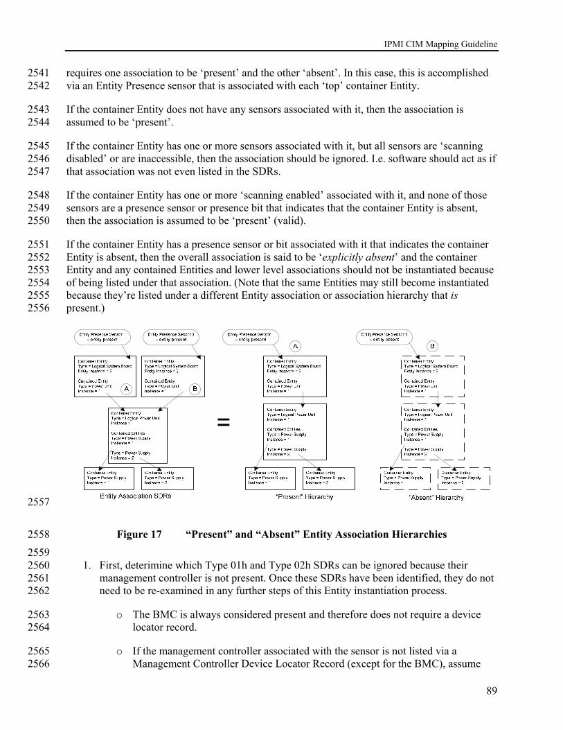
IPMI CIM Mapping Guideline
89
requires one association to be ‘present’ and the other ‘absent’. In this case, this is accomplished 2541 via an Entity Presence sensor that is associated with each ‘top’ container Entity. 2542
If the container Entity does not have any sensors associated with it, then the association is 2543 assumed to be ‘present’. 2544
If the container Entity has one or more sensors associated with it, but all sensors are ‘scanning 2545 disabled’ or are inaccessible, then the association should be ignored. I.e. software should act as if 2546 that association was not even listed in the SDRs. 2547
If the container Entity has one or more ‘scanning enabled’ associated with it, and none of those 2548 sensors are a presence sensor or presence bit that indicates that the container Entity is absent, 2549 then the association is assumed to be ‘present’ (valid). 2550
If the container Entity has a presence sensor or bit associated with it that indicates the container 2551 Entity is absent, then the overall association is said to be ‘explicitly absent’ and the container 2552 Entity and any contained Entities and lower level associations should not be instantiated because 2553 of being listed under that association. (Note that the same Entities may still become instantiated 2554 because they’re listed under a different Entity association or association hierarchy that is 2555 present.) 2556
2557
Figure 17 “Present” and “Absent” Entity Association Hierarchies 2558 2559
1. First, deterimine which Type 01h and Type 02h SDRs can be ignored because their 2560 management controller is not present. Once these SDRs have been identified, they do not 2561 need to be re-examined in any further steps of this Entity instantiation process. 2562
o The BMC is always considered present and therefore does not require a device 2563 locator record. 2564
o If the management controller associated with the sensor is not listed via a 2565 Management Controller Device Locator Record (except for the BMC), assume 2566
IPMI CIM Mapping Guideline
90
any sensors associated with that controller are not present. This relationship can 2567 be identified by examining the fields for Device Slave Address and Channel 2568 Number listed in the Management Controller Device Locator record. These same 2569 values are used in the Type 01h and Type 02h sensor data records. 2570
o For each management controller listed, issue a Get Device ID command to verify 2571 that the controller is accessible. If the controller is not accessible, ignore any Type 2572 01h and Type 02h SDRs associated with sensors for that controller. 2573
2. Next, create a list of Entities that exist under Entity Associations, tagging each entry in 2574 the list with which association the Entity was found under. An Entity could possibly 2575 appear more than once in the list. 2576
o Start by finding the topmost ‘root’ container Entities. These are Entities that are 2577 not themselves listed as being contained Entities in any other Entity Association 2578 record. (The top of every Entity hierarchy must have a unique container Entity. 2579 Thus, the id information for the container Entity can be used as a way to identify a 2580 particular hierarchy) 2581
o Next, for each hiearchy, add the contained Entities to the list under that hierarchy, 2582 and then see if any of the contained Entities are container entities for any other 2583 entity association records. If so, add their contained entities to the list under the 2584 hierarchy and repeat the process until no more container entities are found under 2585 the hierarchy. 2586
o You now should have a list of the different Entity hierarchies (Entity 2587 Associations) and the Entities contained in each hierarchy. Note that at this point, 2588 a given Entity could appear in more than one hierarchy. 2589
3. Next, identify which Entities in the list should not be instantiated because they are 2590 contained under the hierarchy of a Device-relative Entity Association record where the 2591 management controller associated with the top of that heirarchy is not present. 2592
o For each Device-related Entity Association record, check to see whether the 2593 management controller for the record is present and accessible. If the management 2594 controller is not present and accessible, mark the contained Entities in the list as 2595 ‘do not instantiate’. 2596
o Check to see if any of the ‘do not instantiate’ Entities from the previous step are 2597 themselves container entities for either a Device-relative or regular (type 08h) 2598 Entity Association record under the hierarchy. If so, mark any subsequent 2599 contained Entities in that hierarchy as ‘do not instantiate’. Repeat until no more 2600 container entities are found that are listed in the ‘do not instantiate’ list. 2601
4. Next, identify which Entities should not be instantiated because they are contained under 2602 an Entity Assocation (either Device-related or regular [type 08h] ) where the container 2603 Entity is ‘not present’ because an Entity Presence sensorindicates that the container 2604 Entity is not present. 2605
IPMI CIM Mapping Guideline
91
o Check the Type 01h and Type 02h records and see if there is an ‘Entity Presence’ 2606 sensor associated with the container Entity. If so, access the sensor to see if the 2607 status indicates ‘Entity Absent’. If it does, mark the entity as ‘do not instantiate’ 2608 under the hierarchy. 2609
o If the Entity Presence sensor is disabled (not scanning) or inaccessible, assume 2610 the Entity is not present and also mark the entity as ‘do not instantiate’ under the 2611 hierarchy. 2612
At this point, any Entities in the hierarchy lists that are not marked as ‘do not instantiate’ 2613 are available to be instantiated. So you should go through the hierarchies and create two 2614 lists of Entities: a ‘available for instantiation’ list of all the Entities the are are part of a 2615 ‘present’ hierachy, and a ‘do not instantiate’ list, which is the list Entities that were found 2616 in an Entity Association hierarchy and are not on the ‘avaiable for instantiation’ list. 2617
5. Identify whether additional Entities should be instantiated because they’re listed in Type 2618 01h, 02h, or 03h SDRs. 2619
o For each Type 01h, Type 02h, or Type 03h SDR (that isn’t to be ignored because 2620 of step ‘1’) see if the Entity associated with the sensor is on the ‘do not 2621 instantiate’ list. If so, go on to the next SDR. 2622
o Otherwise, check to see if the sensor is of a type that includes a “Presence” bit 2623 that indicates whether the Entity associated with the sensor is present or not. (This 2624 only applies to Type 01h or Type 02h SDRs that support readable sensors). If the 2625 bit indicates the Entity is absent, add that Entity to the ‘do not instantiate’ list and 2626 remove it from ‘available from instantiation’ list if it’s there . Otherwise, add the 2627 Entity to the ‘available for instantiation’ list. 2628
6. Certain types of sensors imply an Entity that can be instantiated under CIM. For example, 2629 Fan and Processor sensors imply the existence of Fan and Processor entities. Identify 2630 Entities that should be instantiated based on the sensor type. 2631
o For each Type 01h, Type 02h, or Type 03h SDR (that isn’t to be ignored because 2632 of step ‘1’) see if the Entity associated with the sensor is on the ‘do not 2633 instantiate’ list. If so, go on to the next SDR. 2634
o If the Sensor Type (Sensor/Event Type) in the SDR does not match the Entity ID 2635 given in the SDR, then a separate Entity based on the sensor type should be added 2636 to the ‘available for instantiation’ list, provided that the Sensor/Event Type is one 2637 of the types in the following table. Since there is not an explicit Entity Instance 2638 number available in this case, an Entity Instance number must be synthesized. The 2639 Entity Instance number should recored as the combination of Sensor Number 2640 (SDR type 1|2 table byte 8), Owner LUN (SDR type 1|2 table byte 7), Owner ID 2641 (SDR type 1|2 table byte 6) so that the instance ID can ultimately be formulated as 2642 a CIM_Sensor.DeviceID [See section 3.4.2.4, CIM_Sensor.DeviceID]. 2643
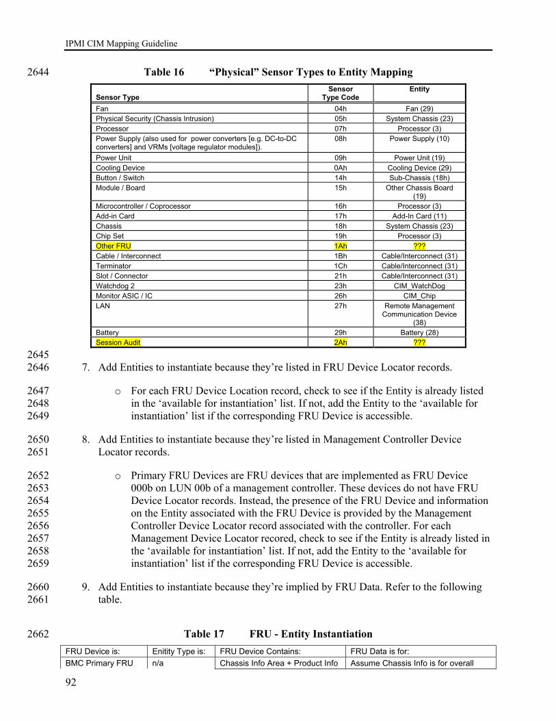
IPMI CIM Mapping Guideline
92
Table 16 “Physical” Sensor Types to Entity Mapping 2644 Sensor Type
Sensor Type Code
Entity
Fan 04h Fan (29) Physical Security (Chassis Intrusion) 05h System Chassis (23) Processor 07h Processor (3)
08h Power Supply (10) Power Supply (also used for power converters [e.g. DC-to-DC converters] and VRMs [voltage regulator modules]). Power Unit 09h Power Unit (19) Cooling Device 0Ah Cooling Device (29) Button / Switch 14h Sub-Chassis (18h) Module / Board 15h Other Chassis Board
(19) Microcontroller / Coprocessor 16h Processor (3) Add-in Card 17h Add-In Card (11) Chassis 18h System Chassis (23) Chip Set 19h Processor (3) Other FRU 1Ah ??? Cable / Interconnect 1Bh Cable/Interconnect (31) Terminator 1Ch Cable/Interconnect (31) Slot / Connector 21h Cable/Interconnect (31) Watchdog 2 23h CIM_WatchDog Monitor ASIC / IC 26h CIM_Chip LAN 27h Remote Management
Communication Device (38)
Battery 29h Battery (28) Session Audit 2Ah ???
2645 7. Add Entities to instantiate because they’re listed in FRU Device Locator records. 2646
o For each FRU Device Location record, check to see if the Entity is already listed 2647 in the ‘available for instantiation’ list. If not, add the Entity to the ‘available for 2648 instantiation’ list if the corresponding FRU Device is accessible. 2649
8. Add Entities to instantiate because they’re listed in Management Controller Device 2650 Locator records. 2651
o Primary FRU Devices are FRU devices that are implemented as FRU Device 2652 000b on LUN 00b of a management controller. These devices do not have FRU 2653 Device Locator records. Instead, the presence of the FRU Device and information 2654 on the Entity associated with the FRU Device is provided by the Management 2655 Controller Device Locator record associated with the controller. For each 2656 Management Device Locator recored, check to see if the Entity is already listed in 2657 the ‘available for instantiation’ list. If not, add the Entity to the ‘available for 2658 instantiation’ list if the corresponding FRU Device is accessible. 2659
9. Add Entities to instantiate because they’re implied by FRU Data. Refer to the following 2660 table. 2661
Table 17 FRU - Entity Instantiation 2662 FRU Device is: Enitity Type is: FRU Device Contains: FRU Data is for: BMC Primary FRU n/a Chassis Info Area + Product Info Assume Chassis Info is for overall
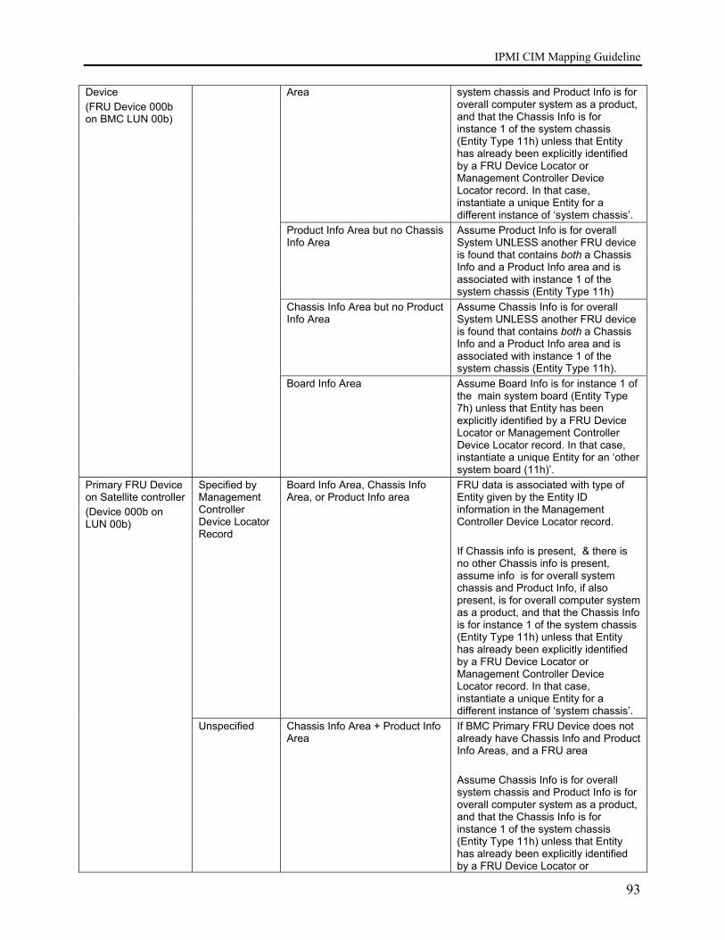
IPMI CIM Mapping Guideline
93
Device (FRU Device 000b on BMC LUN 00b)
Area system chassis and Product Info is for overall computer system as a product, and that the Chassis Info is for instance 1 of the system chassis (Entity Type 11h) unless that Entity has already been explicitly identified by a FRU Device Locator or Management Controller Device Locator record. In that case, instantiate a unique Entity for a different instance of ‘system chassis’.
Product Info Area but no Chassis Info Area
Assume Product Info is for overall System UNLESS another FRU device is found that contains both a Chassis Info and a Product Info area and is associated with instance 1 of the system chassis (Entity Type 11h)
Chassis Info Area but no Product Info Area
Assume Chassis Info is for overall System UNLESS another FRU device is found that contains both a Chassis Info and a Product Info area and is associated with instance 1 of the system chassis (Entity Type 11h).
Board Info Area Assume Board Info is for instance 1 of the main system board (Entity Type 7h) unless that Entity has been explicitly identified by a FRU Device Locator or Management Controller Device Locator record. In that case, instantiate a unique Entity for an ‘other system board (11h)’.
Board Info Area, Chassis Info Area, or Product Info area
Specified by Management Controller Device Locator Record
FRU data is associated with type of Entity given by the Entity ID information in the Management Controller Device Locator record. If Chassis info is present, & there is no other Chassis info is present, assume info is for overall system chassis and Product Info, if also present, is for overall computer system as a product, and that the Chassis Info is for instance 1 of the system chassis (Entity Type 11h) unless that Entity has already been explicitly identified by a FRU Device Locator or Management Controller Device Locator record. In that case, instantiate a unique Entity for a different instance of ‘system chassis’.
Primary FRU Device on Satellite controller (Device 000b on LUN 00b)
Unspecified Chassis Info Area + Product Info Area
If BMC Primary FRU Device does not already have Chassis Info and Product Info Areas, and a FRU area Assume Chassis Info is for overall system chassis and Product Info is for overall computer system as a product, and that the Chassis Info is for instance 1 of the system chassis (Entity Type 11h) unless that Entity has already been explicitly identified by a FRU Device Locator or

IPMI CIM Mapping Guideline
94
Management Controller Device Locator record. Otherwise, instantiate a unique Entity for a different instance of ‘system chassis’ associated with the management controller.
Product Info Area but no Chassis Info Area
Assume Product Info is for overall System UNLESS there is Product Info in the BMC Primary FRU Device, or another FRU device is found that contains both a Chassis Info and a Product Info area and is associated with instance 1 of the system chassis (Entity Type 11h)
Chassis Info Area but no Product Info Area
Assume Chassis Info is for overall System UNLESS there is Chassis Info in the BMC Primary FRU Device, or another FRU device is found that contains both a Chassis Info and a Product Info area and is associated with instance 1 of the system chassis (Entity Type 11h)
Board Info Area Assume Board Info is for instance 1 of the main system board (Entity Type 7h) unless that Entity has been explicitly identified by a FRU Device Locator or Management Controller Device Locator record. In that case, instantiate a unique Entity for an ‘other system board (11h)’.
Specified by FRU Device Locator Record
Board Info Area, Chassis Info Area, or Product Info area
FRU data is associated with type of Entity given by the Entity ID information in the FRU Device Locator record. Any combination of Product, Chassis, and Board Info areas may be present. Appropriate CIM “Package” classes should be instantiated for each type of record. The Entity itself should be added to the ‘available for instantiation’ if not already present.
Chassis Info Area + Product Info Area
If Chassis Info area is present, and a Chassis Info area is not provided in the Primary FRU Device of the BMC, assume Chassis Info is for overall system chassis and Product Info is for overall computer system as a product. Assume Chassis Info is for instance 1 of the system chassis (Entity Type 11h) unless that Entity has already been explicitly identified by a FRU Device Locator or Management Controller Device Locator record. In that case, instantiate a unique Entity for a different instance of ‘system chassis’.
Product Info Area but no Chassis Info Area
Assume Product Info is for overall System UNLESS another FRU device is found that contains both a Chassis Info and a Product Info area.
Identified by FRU Device Locator Record
Unspecified
Chassis Info Area but no Product Info Area
Assume Chassis Info is for overall System UNLESS another FRU device is found that contains both a Chassis Info and a Product Info area and is

IPMI CIM Mapping Guideline
95
either associated with instance 1 of the system chassis (Entity Type 11h), or is in the Primary FRU Device of the BMC.
Board Info Area Board Info is for FRU that the management controller is located on.
10.3.3 Entity Instance Correlation 2663 Instrumentation MUST keep track of the IPMI Entity Instance identifiers and correlate during 2664 SDR discovery so as to only produce one set of CIM instances representing a particular IPMI 2665 entity. 2666
10.4 CIM_PhysicalPackage Mapping 2667
10.4.1 CIM_PhysicalPackage Methods 2668 None. 2669
10.4.2 CIM_PhysicalPackage Properties 2670 REQUIRED properties are properties that MUST be present. RECOMMENDED properties are 2671 properties that MAY be present. For example, there may be properties that are only filled out in 2672 special configurations of the CIM Schema. 2673
Several property vales are dependent on the availability of associated FRU information. The 2674 Product Info Area as defined in Platform Management FRU Information Storage Definition v1.1 2675 is mapped for this class. 2676
Properties that are listed in the Required section in the following table MUST be implemented as 2677 defined in the subsections following this table unless the Notes column for each property 2678 specifies the defining reference. 2679
Table 18 CIM_PhysicalPackage Class Properties 2680
Required Properties Notes Tag Key CreationClassName Key PackageType VendorEquipmentType HealthState OperationalStatus Description ElementName
2681 Recommended Properties Notes
VendorCompatibilityString(E)

IPMI CIM Mapping Guideline
96
Recommended Properties Notes PoweredOn CanBeFRUed Manufacturer If FRU available See 10.4.2.4 Model If FRU available See 10.4.2.5 SKU OtherPackageType RemovalConditions ManufactureDate ActiveCooling Version SerialNumber If FRU available See 10.4.2.7 PartNumber If FRU available See 10.4.2.6 Height Depth Width Weight IdentifyingDescriptions OtherIdentifyingInfo UserTracking StatusDescriptions InstallDate Name If FRU available See 10.4.2.4 Caption
2682
The following subsections describe procedures for generating values for various properties of 2683 CIM classes required in this profile. 2684
10.4.2.1 CIM_PhysicalPackage.Tag 2685 An arbitrary string that uniquely identifies the Physical Element and serves as the Element ’ s 2686 key. 2687
Formulate as string: 2688
(string)<Entity ID from SDR> || (string)<Entity Instance from SDR> 2689
|| (string)<Sensor Number from SDR> 2690
10.4.2.2 CIM_PhysicalPackage.CreationClassName 2691 Per the DMTF definition of the class property: The name of the class or the subclass used in the 2692 creation of an instance. This will typically be “CIM_PhysicalPackage”. 2693

IPMI CIM Mapping Guideline
97
Formulate as a string: 2694
<”CIM_PhysicalPackage” or the name of the subclass created> 2695
10.4.2.3 CIM_PhysicalPackage.PackageType 2696 Values for CIM_PhysicalPackage.PackageType are mapped to values of Entity ID from the 2697 SDR. 2698
Formulate as integer: 2699
if Entity ID = 04h (disk or disk bay) 2700
CIM_PhysicalPackage.PackageType = 15 (Storage Media Package) 2701
elseif EntityID = 05h (peripherial bay) 2702
CIM_PhysicalPackage.PackageType = 5 (Container/Frame Slot) 2703
elseif EntityID = 06h (system management module) 2704
CIM_PhysicalPackage.PackageType = 1 (Other) 2705
CIM_PhysicalPackage.OtherPackageType = “System Management Module” 2706
elseif EntityID = 08h (memory module) 2707
CIM_PhysicalPackage.PackageType = 13 (Memory) 2708
elseif EntityID = 09h (processor module) 2709
CIM_PhysicalPackage.PackageType = 12 (Processor) 2710
elseif EntityID = 0Ah (power supply) 2711
CIM_PhysicalPackage.PackageType = 6 (Power Supply) 2712
elseif EntityID = 13h (power unit/power domain) 2713
CIM_PhysicalPackage.PackageType = 1 (Other) 2714
CIM_PhysicalPackage.OtherPackageType = “Power unit/Power domain” 2715
elseif EntityID = 14h (power module/DC-to-DC converter) 2716
CIM_PhysicalPackage.PackageType = 1 (Other) 2717
CIM_PhysicalPackage.OtherPackageType = “Power module/DC-to-DC converter” 2718
elseif EntityID = 1Ah (disk drive bay) 2719

IPMI CIM Mapping Guideline
98
CIM_PhysicalPackage.PackageType = 1 (Other) 2720
CIM_PhysicalPackage.OtherPackageType = “Disk drive bay” 2721
elseif EntityID = 1Bh (peripheral bay) 2722
CIM_PhysicalPackage.PackageType = 1 (Other) 2723
CIM_PhysicalPackage.OtherPackageType = “Peripheral bay” 2724
elseif EntityID = 1Ch (device bay) 2725
CIM_PhysicalPackage.PackageType = 1 (Other) 2726
CIM_PhysicalPackage.OtherPackageType = “Device bay” 2727
elseif EntityID = 1Eh (fan/cooling unit) 2728
CIM_PhysicalPackage.PackageType = 7 (Fan) 2729
elseif EntityID = 1Fh (cable/interconnect) 2730
CIM_PhysicalPackage.PackageType = 1 (Other) 2731
CIM_PhysicalPackage.OtherPackageType = “Cable/Interconnect” 2732
Elseif EntityID = 20h (memory device) 2733
CIM_PhysicalPackage.PackageType = 13 (Memory) 2734
Elseif EntityID = 24h (system bus) 2735
CIM_PhysicalPackage.PackageType = 4 (Cross Connect/Backplane) 2736
elseif EntityID = 28h (battery) 2737
CIM_PhysicalPackage.PackageType = 1 (Other) 2738
CIM_PhysicalPackage.OtherPackageType = “Battery” 2739
elseif EntityID = 29h (processing blade) 2740
CIM_PhysicalPackage.PackageType = 1 (Other) 2741
CIM_PhysicalPackage.OtherPackageType = “Processing Blade” 2742
elseif EntityID = 2Ah (connectivity switch) 2743
CIM_PhysicalPackage.PackageType = 1 (Other) 2744
CIM_PhysicalPackage.OtherPackageType = “Connectivty Switch” 2745

IPMI CIM Mapping Guideline
99
elseif EntityID = 2Bh (processor/memory module) 2746
CIM_PhysicalPackage.PackageType = 1 (Other) 2747
CIM_PhysicalPackage.OtherPackageType = “Processor/Memory Module” 2748
elseif EntityID = 2Ch (I/O module) 2749
CIM_PhysicalPackage.PackageType = 1 (Other) 2750
CIM_PhysicalPackage.OtherPackageType = “I/O Module” 2751
elseif EntityID = 2Dh (processor/IO module) 2752
CIM_PhysicalPackage.PackageType = 1 (Other) 2753
CIM_PhysicalPackage.OtherPackageType = “Processor/IO Module” 2754
10.4.2.4 CIM_PhysicalPackage.Manufacturer 2755 Formulate as a string: 2756
(string) associated FRU 1.1 Product Info Area – Manufacturer Name field 2757
10.4.2.5 CIM_PhysicalPackage.Model 2758 Formulate as a string: 2759
(string) associated FRU 1.1 Product Info Area – Product Part/Model Number field 2760
10.4.2.6 CIM_PhysicalPackage.PartNumber 2761 Formulate as a string: 2762
(string) associated FRU 1.1 Product Info Area – Product Part/Model Number field 2763
10.4.2.7 CIM_PhysicalPackage.SerialNumber 2764 Formulate as a string: 2765
(string) associated FRU 1.1 Product Info Area – Product Serial Number field 2766
10.4.2.8 CIM_PhysicalPackage.Name 2767 Formulate as a string: 2768
(string) associated FRU 1.1 Product Info Area – Product Name field 2769

IPMI CIM Mapping Guideline
100
10.4.2.9 CIM_PhysicalPackage.HealthState 2770
10.4.2.10 CIM_PhysicalPackage.OperationalStatus 2771
10.4.2.11 CIM_PhysicalPackage.Description 2772 Formulate as string: 2773
(string)< CIM_PhysicalPackage.PackageType or 2774 CIM_PhysicalPackage.OtherPackageType > || “(” || (string)<Entity ID from SDR> || “:” || 2775 (string)<Entity Instance from SDR> 2776
10.4.2.12 CIM_PhysicalPackage.ElementName 2777 Formulate as string: 2778
(string)< CIM_PhysicalPackage.PackageType or 2779 CIM_PhysicalPackage.OtherPackageType > || “(” || (string)<Entity ID from SDR> || “:” || 2780 (string)<Entity Instance from SDR> 2781
10.5 CIM_Card Mapping 2782
10.5.1 CIM_Card Methods 2783 None. 2784
10.5.2 CIM_Card Properties 2785 REQUIRED properties are properties that MUST be present. RECOMMENDED properties are 2786 properties that MAY be present. For example, there may be properties that are only filled out in 2787 special configurations of the CIM Schema. 2788
Several property vales are dependent on the availability of associated FRU information. The 2789 Board Info Area as defined in Platform Management FRU Information Storage Definition v1.1 is 2790 mapped for this class. 2791
Properties that are listed in the Required section in the following table MUST be implemented as 2792 defined in the subsections following this table unless the Notes column for each property 2793 specifies the defining reference. 2794

IPMI CIM Mapping Guideline
101
Table 19 CIM_Card Class Properties 2795
Required Properties Notes Tag Key CreationClassName Key HostingBoard PackageType OtherPackageType HealthState OperationalStatus Description ElementName
2796 Recommended Properties Notes
Manufacturer If FRU available See 10.5.2.5 Model SKU VendorEquipmentType VendorCompatibilityString(E) PoweredOn CanBeFRUed SlotLayout RequiresDaughterBoard SpecialRequirements RequirementsDescription OperatingVoltages RemovalConditions ManufactureDate If FRU available See 10.5.2.6 ActiveCooling Version SerialNumber If FRU available See 10.5.2.8 PartNumber If FRU available See 10.5.2.7 Height Depth Width Weight IdentifyingDescriptions OtherIdentifyingInfo UserTracking StatusDescriptions InstallDate Name If FRU available See 10.5.2.9
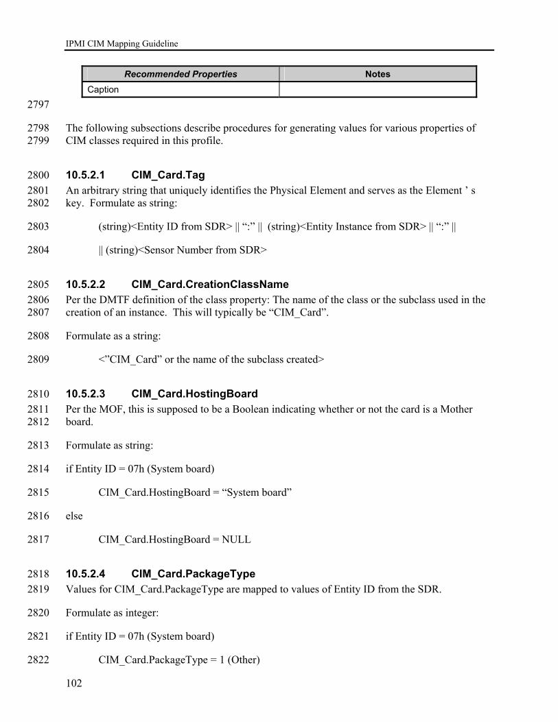
IPMI CIM Mapping Guideline
102
Recommended Properties Notes Caption
2797
The following subsections describe procedures for generating values for various properties of 2798 CIM classes required in this profile. 2799
10.5.2.1 CIM_Card.Tag 2800 An arbitrary string that uniquely identifies the Physical Element and serves as the Element ’ s 2801 key. Formulate as string: 2802
(string)<Entity ID from SDR> || “:” || (string)<Entity Instance from SDR> || “:” || 2803
|| (string)<Sensor Number from SDR> 2804
10.5.2.2 CIM_Card.CreationClassName 2805 Per the DMTF definition of the class property: The name of the class or the subclass used in the 2806 creation of an instance. This will typically be “CIM_Card”. 2807
Formulate as a string: 2808
<”CIM_Card” or the name of the subclass created> 2809
10.5.2.3 CIM_Card.HostingBoard 2810 Per the MOF, this is supposed to be a Boolean indicating whether or not the card is a Mother 2811 board. 2812
Formulate as string: 2813
if Entity ID = 07h (System board) 2814
CIM_Card.HostingBoard = “System board” 2815
else 2816
CIM_Card.HostingBoard = NULL 2817
10.5.2.4 CIM_Card.PackageType 2818 Values for CIM_Card.PackageType are mapped to values of Entity ID from the SDR. 2819
Formulate as integer: 2820
if Entity ID = 07h (System board) 2821
CIM_Card.PackageType = 1 (Other) 2822
IPMI CIM Mapping Guideline
103
CIM_Card.OtherPackageType = “System board” 2823
elseif EntityID = 0Bh (Add-in card) 2824
CIM_Card.PackageType = 1 (Other) 2825
CIM_Card.OtherPackageType = “Add-in card” 2826
elseif EntityID = 0Ch (Front panel board) 2827
CIM_Card.PackageType = 1 (Other) 2828
CIM_Card.OtherPackageType = “Front panel board” 2829
elseif EntityID = 0Dh (Back panel board) 2830
CIM_Card.PackageType = 1 (Other) 2831
CIM_Card.OtherPackageType = “Back panel board” 2832
elseif EntityID = 0Eh (Power system board) 2833
CIM_Card.PackageType = 1 (Other) 2834
CIM_Card.OtherPackageType = “Power system board” 2835
elseif EntityID = 0Fh (Drive backplane) 2836
CIM_Card.PackageType = 1 (Other) 2837
CIM_Card.OtherPackageType = “Drive backplane” 2838
elseif EntityID = 10h (System internal expansion backplane) 2839
CIM_Card.PackageType = 1 (Other) 2840
CIM_Card.OtherPackageType = “System internal expansion backplane” 2841
elseif EntityID = 11h (Other system board) 2842
CIM_Card.PackageType = 1 (Other) 2843
CIM_Card.OtherPackageType = “Other system board” 2844
elseif EntityID = 12h (Processor board) 2845
CIM_Card.PackageType = 1 (Other) 2846
CIM_Card.OtherPackageType = “Processor board” 2847
elseif EntityID = 15h (Power management/power distribution board) 2848
IPMI CIM Mapping Guideline
104
CIM_Card.PackageType = 1 (Other) 2849
CIM_Card.OtherPackageType = “Power management/power distribution board” 2850
elseif EntityID = 16h (Chassis back panel board) 2851
CIM_Card.PackageType = 1 (Other) 2852
CIM_Card.OtherPackageType = “Chassis back panel board” 2853
elseif EntityID = 19h (Other chassis board) 2854
CIM_Card.PackageType = 1 (Other) 2855
CIM_Card.OtherPackageType = “Other chassis board” 2856
elseif EntityID = 26h (Remote management card) 2857
CIM_Card.PackageType = 1 (Other) 2858
CIM_Card.OtherPackageType = “Remote management card” 2859
10.5.2.5 CIM_Card.Manufacturer 2860 Formulate as a string: 2861
(string) associated FRU 1.1 Board Info Area – Board Manufacturer Name field 2862
10.5.2.6 CIM_ Card.ManufacturerDate 2863 Formulate as a string: 2864
(CIM datetime data type) associated FRU 1.1 Board Info Area – Mfg. Date/Time field 2865
10.5.2.7 CIM_ Card.PartNumber 2866 Formulate as a string: 2867
(string) associated FRU 1.1 Board Info Area – Board Part/Model Number field 2868
10.5.2.8 CIM_ Card.SerialNumber 2869 Formulate as a string: 2870
(string) associated FRU 1.1 Board Info Area – Board Serial Number field 2871
10.5.2.9 CIM_ Card.Name 2872 Formulate as a string: 2873
IPMI CIM Mapping Guideline
105
(string) associated FRU 1.1 Board Info Area – Board Product Name field 2874
10.5.2.10 CIM_Card.HealthState 2875
10.5.2.11 CIM_Card.OperationalStatus 2876
10.5.2.12 CIM_Card.Description 2877 Formulate as string: 2878
(string)< CIM_Card.PackageType or CIM_Card.OtherPackageType > || “(” || 2879 (string)(SensorNumber) || “.” || (string)(OwnerLUN) || “.” || string)(OwnerID) || “): ” 2880 ||(string)(EStr(<CIM_Sensor.SensorType>)) || “ for ” || (string)(<IPMI_SDR_EntityID>) 2881 || “ “ || (string)(<IPMI_SDR_EntityInstanceNumber>) 2882
10.5.2.13 CIM_Card.ElementName 2883 Formulate as string: 2884
(string)< )< CIM_Card.PackageType or CIM_Card.OtherPackageType > || “(” || 2885 (string)<Entity ID from SDR> || “:” || (string)<Entity Instance from SDR> || “)” 2886
10.6 CIM_Chip Mapping 2887
10.6.1 CIM_Chip Methods 2888 None. 2889
10.6.2 CIM_Chip Properties 2890 REQUIRED properties are properties that MUST be present. RECOMMENDED properties are 2891 properties that MAY be present. For example, there may be properties that are only filled out in 2892 special configurations of the CIM Schema. 2893
Properties that are are listed in the Required section in the following table MUST be 2894 implemented as defined in the subsections following this table unless the Notes column for each 2895 property specifies the defining reference. 2896

IPMI CIM Mapping Guideline
106
Table 20 CIM_Chip Class Properties 2897
Required Properties Notes Tag Key CreationClassName Key HealthState OperationalStatus Description ElementName
2898 Recommended Properties Notes
Manufacturer Model Version VendorEquipmentType PoweredOn CanBeFRUed SKU RemovalConditions ManufactureDate Removable Replaceable HotSwappable UserTracking Version SerialNumber PartNumber FormFactor StatusDescriptions InstallDate Name Caption
2899
The following subsections describe procedures for generating values for various properties of 2900 CIM classes required in this profile. 2901
10.6.2.1 CIM_Chip.Tag 2902 An arbitrary string that uniquely identifies the Physical Element and serves as the Element ’ s 2903 key. Formulate as string: 2904
(string)<Entity ID from SDR> || “:” || (string)<Entity Instance from SDR> || “:” || 2905

IPMI CIM Mapping Guideline
107
|| (string)<Sensor Number from SDR> 2906
10.6.2.2 CIM_Chip.CreationClassName 2907 Per the DMTF definition of the class property: The name of the class or the subclass used in the 2908 creation of an instance. This will typically be “CIM_Chip”. 2909
Formulate as a string: 2910
<”CIM_Chip” or the name of the subclass created> 2911
10.6.2.3 CIM_Chip.HealthState 2912
10.6.2.4 CIM_Chip.OperationalStatus 2913
10.6.2.5 CIM_Chip.Description 2914 Formulate as string: 2915
(string)< SDR entry bytes 49+, see IPMI v1.5 Table 37-1> || “(” || 2916 (string)(SensorNumber) || “.” || (string)(OwnerLUN) || “.” || string)(OwnerID) || “): ” 2917 ||(string)(EStr(<CIM_Sensor.SensorType>)) || “ for ” || (string)(<IPMI_SDR_EntityID>) 2918 || “ “ || (string)(<IPMI_SDR_EntityInstanceNumber>) 2919
10.6.2.6 CIM_Chip.ElementName 2920 Formulate as string: 2921
(string)< SDR entry bytes 49+, see IPMI v1.5 Table 37-1> || “(” || (string)<Entity ID from SDR> 2922 || “:” || (string)<Entity Instance from SDR> || “)” 2923
10.7 CIM_Chassis Mapping 2924
10.7.1 CIM_Chassis Methods 2925 None Defined. 2926
10.7.2 CIM_Chassis Properties 2927 REQUIRED properties are properties that MUST be present. RECOMMENDED properties are 2928 properties that MAY be present. For example, there may be properties that are only filled out in 2929 special configurations of the CIM Schema. 2930
Several property vales are dependent on the availability of associated FRU information. The 2931 Chassis Info Area as defined in Platform Management FRU Information Storage Definition v1.1 2932 is mapped for this class. 2933

IPMI CIM Mapping Guideline
108
Properties that are listed in the Required section in the following table MUST be implemented as 2934 defined in the subsections following this table unless the Notes column for each property 2935 specifies the defining reference. 2936
Table 21 CIM_Chassis Class Properties 2937
Required Properties Notes Tag Key CreationClassName Key ChassisPackageType HealthState OperationalStatus Description ElementName
2938 Recommended Properties Notes
Manufacturer Model SKU VendorEquipmentType VendorCompatibilityString(E) PoweredOn CanBeFRUed LockPresent NumberOfPowerCords CurrentRequiredOrProduced HeatGeneration ChassisTypeDescription MultipleSystemSupport RackMountable CableManagementStrategy ServicePhilosophy ServiceDescriptions AudibleAlarm VisibleAlarm SecurityBreach BreachDescription IsLocked OtherPackageType RemovalConditions ManufactureDate ActiveCooling
IPMI CIM Mapping Guideline
109
Recommended Properties Notes Version SerialNumber If FRU available See Section 10.7.2.5 PartNumber If FRU available See Section 10.7.2.4 Height Depth Width Weight IdentifyingDescriptions OtherIdentifyingInfo UserTracking StatusDescriptions InstallDate Name Caption
10.7.2.1 CIM_Chassis.Tag 2939 An arbitrary string that uniquely identifies the Physical Element and serves as the Element ’ s 2940 key. Formulate as a string: 2941 2942
(string)<Entity ID from SDR> || “:” || (string)<Entity Instance from SDR> || “:” || 2943
|| (string)<Sensor Number from SDR> 2944
10.7.2.2 CIM_Chassis.CreationClassName 2945 Per the DMTF definition of the class property: The name of the class or the subclass used in the 2946 creation of an instance. This will typically be “CIM_Chassis”. 2947
Formulate as a string: 2948
<”CIM_Chassis” or the name of the subclass created> 2949
2950
10.7.2.3 CIM_Chassis.ChassisPackageType 2951 Values for CIM_Chassis.ChassisPackageType are mapped to values of Entity ID from the SDR. 2952
Formulate as integer: 2953
if Entity ID = 17h (System chassis) 2954
CIM_Chassis.ChassisPackageType = 17 (Main System Chassis) 2955
elseif EntityID = 18h (Sub-chassis) 2956

IPMI CIM Mapping Guideline
110
CIM_Chassis.ChassisPackageType = 19 (SubChassis) 2957
10.7.2.4 CIM_ Chassis.PartNumber 2958 Formulate as a string: 2959
(string) associated FRU 1.1 Chassis Info Area – Chassis Part Number field 2960
10.7.2.5 CIM_ Chassis.SerialNumber 2961 Formulate as a string: 2962
(string) associated FRU 1.1 Chassis Info Area – Chassis Serial Number field 2963
10.7.2.6 CIM_Chassis.HealthState 2964
10.7.2.7 CIM_Chassis.OperationalStatus 2965
10.7.2.8 CIM_Chassis.Description 2966 Formulate as string: 2967
(string)< CIM_Chassis.ChassisPackageType > || “(” || (string)(SensorNumber) || “.” || 2968 (string)(OwnerLUN) || “.” || string)(OwnerID) || “): ” 2969 ||(string)(EStr(<CIM_Sensor.SensorType>)) || “ for ” || (string)(<IPMI_SDR_EntityID>) 2970 || “ “ || (string)(<IPMI_SDR_EntityInstanceNumber>) 2971
10.7.2.9 CIM_Chassis.ElementName 2972 Formulate as string: 2973
(string)<CIM_Chassis.ChassisPackageType> || “(” || (string)<Entity ID from SDR> || “:” 2974 || (string)<Entity Instance from SDR> || “)” 2975
2976
10.8 CIM_Processor Mapping 2977
10.8.1 CIM_Processor Methods 2978 No Mapping Defined. 2979
10.8.2 CIM_Processor Properties 2980 REQUIRED properties are properties that MUST be present. RECOMMENDED properties are 2981 properties that MAY be present. For example, there may be properties that are only filled out in 2982 special configurations of the CIM Schema. 2983
IPMI CIM Mapping Guideline
111
Properties that are listed in the Required section in the following table MUST be implemented as 2984 defined in the subsections following this table unless the Notes column for each property 2985 specifies the defining reference. 2986
Table 22 CIM_Processor Class Properties 2987
Required Properties Notes SystemCreationClassName Key SystemName Key CreationClassName Key DeviceID Key UniqueID EnabledState HealthState OperationalStatus Description ElementName
2988 Recommended Properties Notes
Family CurrentClockSpeed MaxClockSpeed ExternalClockSpeed Role OtherFamilyDescription DataWidth AddressWidth Stepping CPUStatus OtherEnabledState StatusDescriptions Name Caption Description UpgradeMethod LoadPercentage IdentifyingDescriptions AdditionalAvailablity OtherIdentifyingInfo TimeOfLastChange InstallDate

IPMI CIM Mapping Guideline
112
Recommended Properties Notes ElementName
10.8.2.1 CIM_Processor.SystemCreationClassName 2989 The name of the class or the subclass used in the creation of an instance of the containing 2990 system. This will typically be “CIM_ComputerSystem”. 2991
Formulate as a string: 2992
<”CIM_ComputerSystem” or the name of the subclass created> 2993
2994
10.8.2.2 CIM_Processor.CreationClassName 2995 Per the DMTF definition of the class property: The name of the class or the subclass used in the 2996 creation of an instance. This will typically be “CIM_Processor”. 2997
Formulate as a string: 2998
<”CIM_Processor” or the name of the subclass created> 2999
10.8.2.3 CIM_Processor.SystemName 3000 The host name of the containing system. Derived from the CIM_ComputerSystem.Name 3001 property of the instance representing the containing system. 3002
Formulate as a string: 3003
<CIM_ComputerSystem.Name> 3004
10.8.2.4 CIM_Processor.DeviceID 3005 Formulate as string: 3006
(string)<Entity ID from SDR> || “:” || (string)<Entity Instance from SDR> || “:” || 3007
|| (string)<Sensor Number from SDR> || “:” || <”Processor”> 3008
10.8.2.5 CIM_Processor.UniqueID 3009
10.8.2.6 CIM_Processor.EnabledState 3010 Formulate as string: 3011 3012 If Sensor offset 08h (Processor Disabled) = 1b 3013 <”Disabled”> 3014 Else 3015 <”Enabled” 3016

IPMI CIM Mapping Guideline
113
10.8.2.7 CIM_Processor.Description 3017 Formulate as string: 3018
(string) “Processor” || “(” || (string)(SensorNumber) || “.” || (string)(OwnerLUN) || “.” || 3019 string)(OwnerID) || “)” || “ for ” || (string)(<IPMI_SDR_EntityID>) || “ “ || 3020 (string)(<IPMI_SDR_EntityInstanceNumber>) 3021
10.8.2.8 CIM_Processor.ElementName 3022 Formulate as string: 3023
(string)< SDR entry bytes 49+, see IPMI v1.5 Table 37-1> || “(” || (string)<Entity ID from SDR> 3024 || “:” || (string)<Entity Instance from SDR> || “)” 3025
3026
10.8.2.9 CIM_Processor.HealthState 3027
10.8.2.10 CIM_Processor.OperationalStatus 3028
10.9 CIM_Fan Mapping 3029
10.9.1 CIM_Fan Methods 3030 No Mapping Defined. 3031
10.9.2 CIM_Fan Properties 3032 REQUIRED properties are properties that MUST be present. RECOMMENDED properties are 3033 properties that MAY be present. For example, there may be properties that are only filled out in 3034 special configurations of the CIM Schema. 3035
Properties that are listed in the Required section in the following table MUST be implemented as 3036 defined in the subsections following this table unless the Notes column for each property 3037 specifies the defining reference. 3038
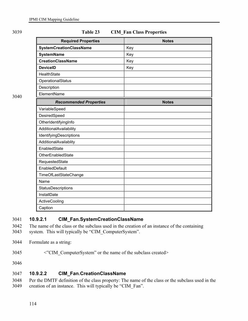
IPMI CIM Mapping Guideline
114
Table 23 CIM_Fan Class Properties 3039
Required Properties Notes SystemCreationClassName Key SystemName Key CreationClassName Key DeviceID Key HealthState OperationalStatus Description ElementName
3040 Recommended Properties Notes
VariableSpeed DesiredSpeed OtherIdentifyingInfo AdditionalAvailability IdentifyingDescriptions AdditionalAvailablity EnabledState OtherEnabledState RequestedState EnabledDefault TimeOfLastStateChange Name StatusDescriptions InstallDate ActiveCooling Caption
10.9.2.1 CIM_Fan.SystemCreationClassName 3041 The name of the class or the subclass used in the creation of an instance of the containing 3042 system. This will typically be “CIM_ComputerSystem”. 3043
Formulate as a string: 3044
<”CIM_ComputerSystem” or the name of the subclass created> 3045
3046
10.9.2.2 CIM_Fan.CreationClassName 3047 Per the DMTF definition of the class property: The name of the class or the subclass used in the 3048 creation of an instance. This will typically be “CIM_Fan”. 3049

IPMI CIM Mapping Guideline
115
Formulate as a string: 3050
<”CIM_Fan” or the name of the subclass created> 3051
10.9.2.3 CIM_Fan.SystemName 3052 The host name of the containing system. Derived from the CIM_ComputerSystem.Name 3053 property of the instance representing the containing system. 3054
Formulate as a string: 3055
<CIM_ComputerSystem.Name> 3056
10.9.2.4 CIM_Fan.DeviceID 3057 Formulate as string: 3058
(string)<Entity ID from SDR> || “:” || (string)<Entity Instance from SDR> || “:” || 3059
|| (string)<Sensor Number from SDR> || “:” || <”Fan”> 3060
3061
10.9.2.5 CIM_Fan.Description 3062 Formulate as string: 3063
“Fan” || “(” || (string)(SensorNumber) || “.” || (string)(OwnerLUN) || “.” || 3064 string)(OwnerID) || “) ” || “ for ” || (string)(<IPMI_SDR_EntityID>) || “ “ || 3065 (string)(<IPMI_SDR_EntityInstanceNumber>) 3066
10.9.2.6 CIM_Fan.ElementName 3067 Formulate as string: 3068
(string)< SDR entry bytes 49+, see IPMI v1.5 Table 37-1> || “(” || (string)<Entity ID from 3069 SDR> || “:” || (string)<Entity Instance from SDR> || “)” 3070
10.9.2.7 CIM_Fan.HealthState 3071
10.9.2.8 CIM_Fan.OperationalStatus 3072
10.10 CIM_PowerSupply Mapping 3073
10.10.1 CIM_PowerSupply Methods 3074 No Mapping Defined. 3075
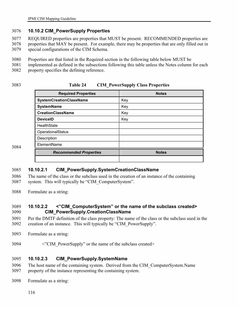
IPMI CIM Mapping Guideline
116
10.10.2 CIM_PowerSupply Properties 3076 REQUIRED properties are properties that MUST be present. RECOMMENDED properties are 3077 properties that MAY be present. For example, there may be properties that are only filled out in 3078 special configurations of the CIM Schema. 3079
Properties are that listed in the Required section in the following table below MUST be 3080 implemented as defined in the subsections following this table unless the Notes column for each 3081 property specifies the defining reference. 3082
Table 24 CIM_PowerSupply Class Properties 3083
Required Properties Notes SystemCreationClassName Key SystemName Key CreationClassName Key DeviceID Key HealthState OperationalStatus Description ElementName
3084 Recommended Properties Notes
10.10.2.1 CIM_PowerSupply.SystemCreationClassName 3085 The name of the class or the subclass used in the creation of an instance of the containing 3086 system. This will typically be “CIM_ComputerSystem”. 3087
Formulate as a string: 3088
10.10.2.2 <”CIM_ComputerSystem” or the name of the subclass created> 3089 CIM_PowerSupply.CreationClassName 3090
Per the DMTF definition of the class property: The name of the class or the subclass used in the 3091 creation of an instance. This will typically be “CIM_PowerSupply”. 3092
Formulate as a string: 3093
<”CIM_PowerSupply” or the name of the subclass created> 3094
10.10.2.3 CIM_PowerSupply.SystemName 3095 The host name of the containing system. Derived from the CIM_ComputerSystem.Name 3096 property of the instance representing the containing system. 3097
Formulate as a string: 3098

IPMI CIM Mapping Guideline
117
<CIM_ComputerSystem.Name> 3099
10.10.2.4 CIM_PowerSupply.DeviceID 3100 Formulate as string: 3101
(string)<Entity ID from SDR> || “:” || (string)<Entity Instance from SDR> || “:” || 3102
|| (string)<Sensor Number from SDR> || “:” || <”Power Supply”> 3103
10.10.2.5 CIM_PowerSupply.Description 3104 Formulate as string: 3105
“Power Supply” || “(” || (string)(SensorNumber) || “.” || (string)(OwnerLUN) || “.” || 3106 string)(OwnerID) || “) ” || “ for ” || (string)(<IPMI_SDR_EntityID>) || “ “ || 3107 (string)(<IPMI_SDR_EntityInstanceNumber>) 3108
10.10.2.6 CIM_PowerSupply.ElementName 3109 Formulate as string: 3110
(string)< SDR entry bytes 49+, see IPMI v1.5 Table 37-1> || “(” || (string)<Entity ID 3111 from SDR> || “:” || (string)<Entity Instance from SDR> || “)” 3112
10.10.2.7 CIM_PowerSupply.HealthState 3113
10.10.2.8 CIM_PowerSupply.OperationalStatus 3114
10.11 CIM_Memory Mapping 3115
10.11.1 CIM_Memory Methods 3116 No Mapping Defined. 3117
10.11.2 CIM_Memory Properties 3118 REQUIRED properties are properties that MUST be present. RECOMMENDED properties are 3119 properties that MAY be present. For example, there may be properties that are only filled out in 3120 special configurations of the CIM Schema. 3121
Properties that are listed in the Required section in the following table MUST be implemented as 3122 defined in the subsections following this table unless the Notes column for each property 3123 specifies the defining reference. 3124
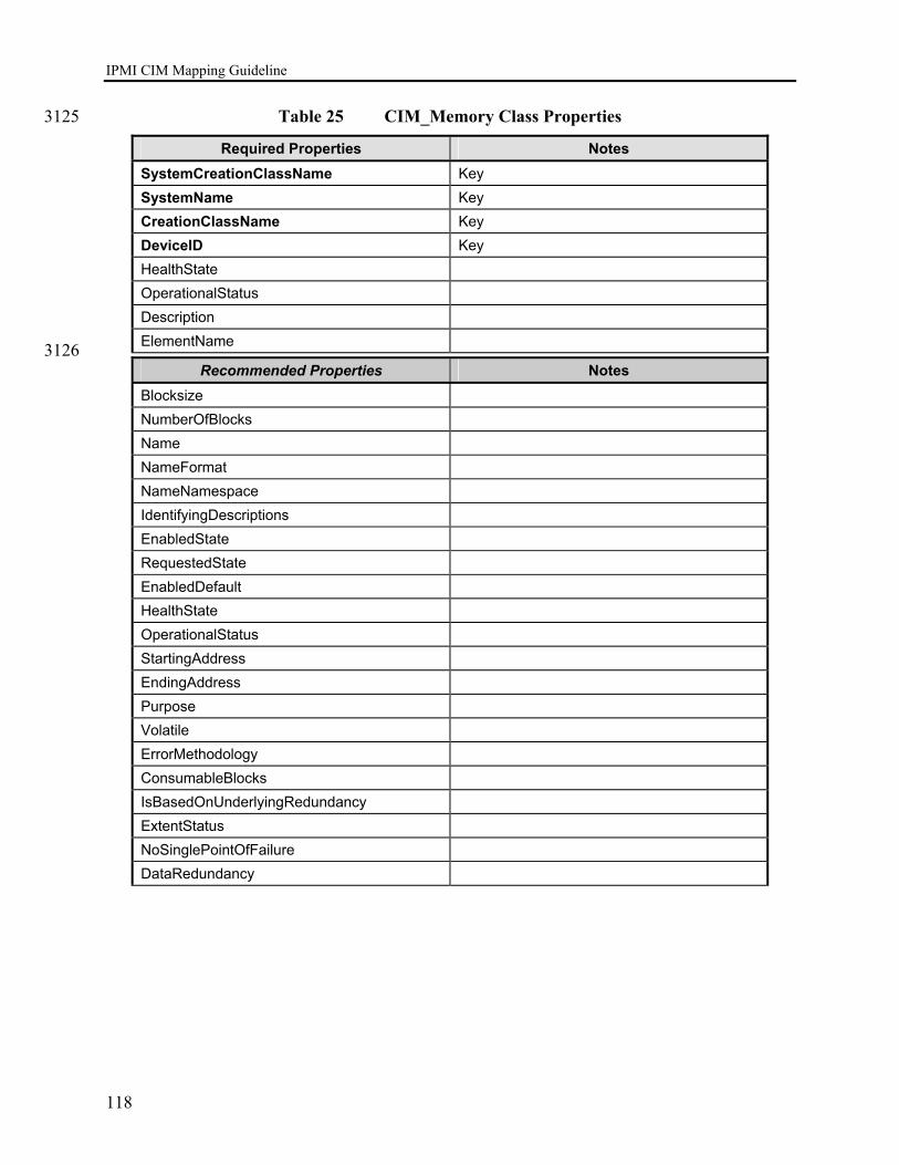
IPMI CIM Mapping Guideline
118
Table 25 CIM_Memory Class Properties 3125
Required Properties Notes SystemCreationClassName Key SystemName Key CreationClassName Key DeviceID Key HealthState OperationalStatus Description ElementName
3126 Recommended Properties Notes
Blocksize NumberOfBlocks Name NameFormat NameNamespace IdentifyingDescriptions EnabledState RequestedState EnabledDefault HealthState OperationalStatus StartingAddress EndingAddress Purpose Volatile ErrorMethodology ConsumableBlocks IsBasedOnUnderlyingRedundancy ExtentStatus NoSinglePointOfFailure DataRedundancy
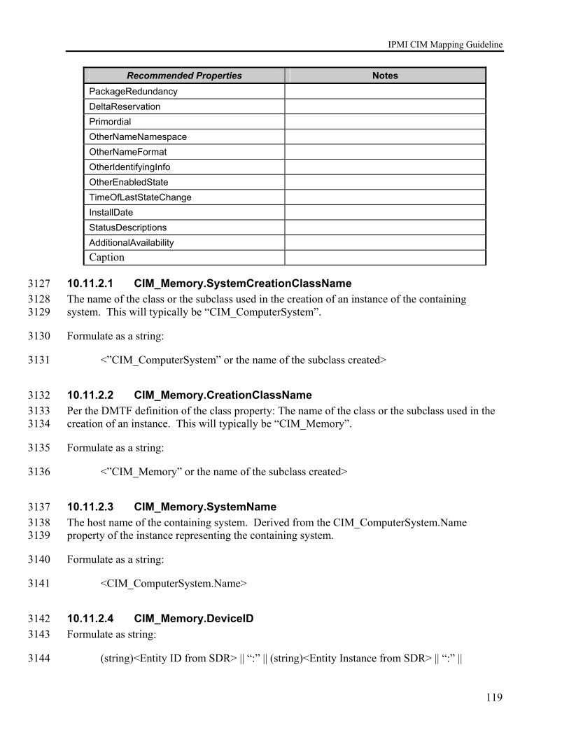
IPMI CIM Mapping Guideline
119
Recommended Properties Notes PackageRedundancy DeltaReservation Primordial OtherNameNamespace OtherNameFormat OtherIdentifyingInfo OtherEnabledState TimeOfLastStateChange InstallDate StatusDescriptions AdditionalAvailability Caption
10.11.2.1 CIM_Memory.SystemCreationClassName 3127 The name of the class or the subclass used in the creation of an instance of the containing 3128 system. This will typically be “CIM_ComputerSystem”. 3129
Formulate as a string: 3130
<”CIM_ComputerSystem” or the name of the subclass created> 3131
10.11.2.2 CIM_Memory.CreationClassName 3132 Per the DMTF definition of the class property: The name of the class or the subclass used in the 3133 creation of an instance. This will typically be “CIM_Memory”. 3134
Formulate as a string: 3135
<”CIM_Memory” or the name of the subclass created> 3136
10.11.2.3 CIM_Memory.SystemName 3137 The host name of the containing system. Derived from the CIM_ComputerSystem.Name 3138 property of the instance representing the containing system. 3139
Formulate as a string: 3140
<CIM_ComputerSystem.Name> 3141
10.11.2.4 CIM_Memory.DeviceID 3142 Formulate as string: 3143
(string)<Entity ID from SDR> || “:” || (string)<Entity Instance from SDR> || “:” || 3144

IPMI CIM Mapping Guideline
120
|| (string)<Sensor Number from SDR> || “:” || <”Memory”> 3145
10.11.2.5 CIM_Memory.Description 3146 Formulate as string: 3147
“Memory” || “(” || (string)(SensorNumber) || “.” || (string)(OwnerLUN) || “.” || 3148 string)(OwnerID) || “) ” || “ for ” || (string)(<IPMI_SDR_EntityID>) || “ “ || 3149 (string)(<IPMI_SDR_EntityInstanceNumber>) 3150
10.11.2.6 CIM_Memory.ElementName 3151 Formulate as string: 3152
(string)< SDR entry bytes 49+, see IPMI v1.5 Table 37-1> || “(” || (string)<Entity ID 3153 from SDR> || “:” || (string)<Entity Instance from SDR> || “)” 3154
3155
10.11.2.7 CIM_Memory.HealthState 3156
10.11.2.8 CIM_Memory.OperationalStatus 3157
10.12 CIM_Battery Mapping 3158
10.12.1 CIM_Battery Methods 3159 No Mapping Defined. 3160
10.12.2 CIM_Battery Properties 3161 REQUIRED properties are properties that MUST be present. RECOMMENDED properties are 3162 properties that MAY be present. For example, there may be properties that are only filled out in 3163 special configurations of the CIM Schema. 3164
Properties that are listed in the Required section in the following table MUST be implemented as 3165 defined in the subsections following this table unless the Notes column for each property 3166 specifies the defining reference. 3167
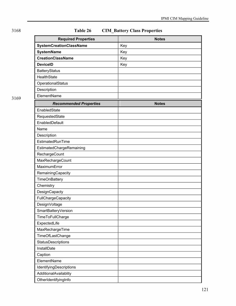
IPMI CIM Mapping Guideline
121
Table 26 CIM_Battery Class Properties 3168
Required Properties Notes SystemCreationClassName Key SystemName Key CreationClassName Key DeviceID Key BatteryStatus HealthState OperationalStatus Description ElementName
3169 Recommended Properties Notes
EnabledState RequestedState EnabledDefault Name Description EstimatedRunTime EstimatedChargeRemaining RechargeCount MaxRechargeCount MaximumError RemainingCapacity TimeOnBattery Chemistry DesignCapacty FullChargeCapacity DesignVoltage SmartBatteryVersion TimeToFullCharge ExpectedLife MaxRechargeTime TimeOfLastChange StatusDescriptions InstallDate Caption ElementName IdentifyingDescriptions AdditionalAvailablity OtherIdentifyingInfo

IPMI CIM Mapping Guideline
122
Recommended Properties Notes OtherEnabledState
10.12.2.1 CIM_Battery.SystemCreationClassName 3170 The name of the class or the subclass used in the creation of an instance of the containing 3171 system. This will typically be “CIM_ComputerSystem”. 3172
Formulate as a string: 3173
<”CIM_ComputerSystem” or the name of the subclass created> 3174
3175
10.12.2.2 CIM_Battery.CreationClassName 3176 Per the DMTF definition of the class property: The name of the class or the subclass used in the 3177 creation of an instance. This will typically be “CIM_Battery”. 3178
Formulate as a string: 3179
<”CIM_Battery” or the name of the subclass created> 3180
10.12.2.3 CIM_Battery.SystemName 3181 The host name of the containing system. Derived from the CIM_ComputerSystem.Name 3182 property of the instance representing the containing system. 3183
Formulate as a string: 3184
<CIM_ComputerSystem.Name> 3185
10.12.2.4 CIM_Battery.DeviceID 3186 Formulate as string: 3187
(string)<Entity ID from SDR> || “:” || (string)<Entity Instance from SDR> || “:” || 3188
|| (string)<Sensor Number from SDR> || “:” || <”Battery”> 3189
10.12.2.5 CIM_Battery.BatteryStatus 3190
10.12.2.6 CIM_Battery.Description 3191 Formulate as string: 3192
“Battery” || “(” || (string)(SensorNumber) || “.” || (string)(OwnerLUN) || “.” || 3193 string)(OwnerID) || “) ” || “ for ” || (string)(<IPMI_SDR_EntityID>) || “ “ || 3194 (string)(<IPMI_SDR_EntityInstanceNumber>) 3195
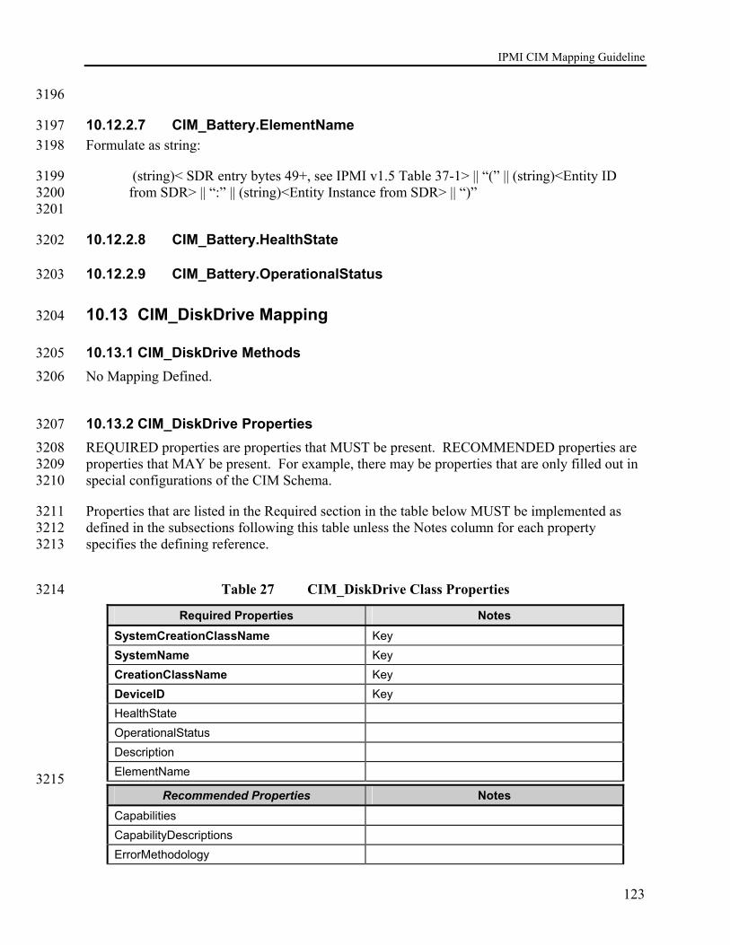
IPMI CIM Mapping Guideline
123
3196
10.12.2.7 CIM_Battery.ElementName 3197 Formulate as string: 3198
(string)< SDR entry bytes 49+, see IPMI v1.5 Table 37-1> || “(” || (string)<Entity ID 3199 from SDR> || “:” || (string)<Entity Instance from SDR> || “)” 3200
3201
10.12.2.8 CIM_Battery.HealthState 3202
10.12.2.9 CIM_Battery.OperationalStatus 3203
10.13 CIM_DiskDrive Mapping 3204
10.13.1 CIM_DiskDrive Methods 3205 No Mapping Defined. 3206
10.13.2 CIM_DiskDrive Properties 3207 REQUIRED properties are properties that MUST be present. RECOMMENDED properties are 3208 properties that MAY be present. For example, there may be properties that are only filled out in 3209 special configurations of the CIM Schema. 3210
Properties that are listed in the Required section in the table below MUST be implemented as 3211 defined in the subsections following this table unless the Notes column for each property 3212 specifies the defining reference. 3213
Table 27 CIM_DiskDrive Class Properties 3214
Required Properties Notes SystemCreationClassName Key SystemName Key CreationClassName Key DeviceID Key HealthState OperationalStatus Description ElementName
3215 Recommended Properties Notes
Capabilities CapabilityDescriptions ErrorMethodology
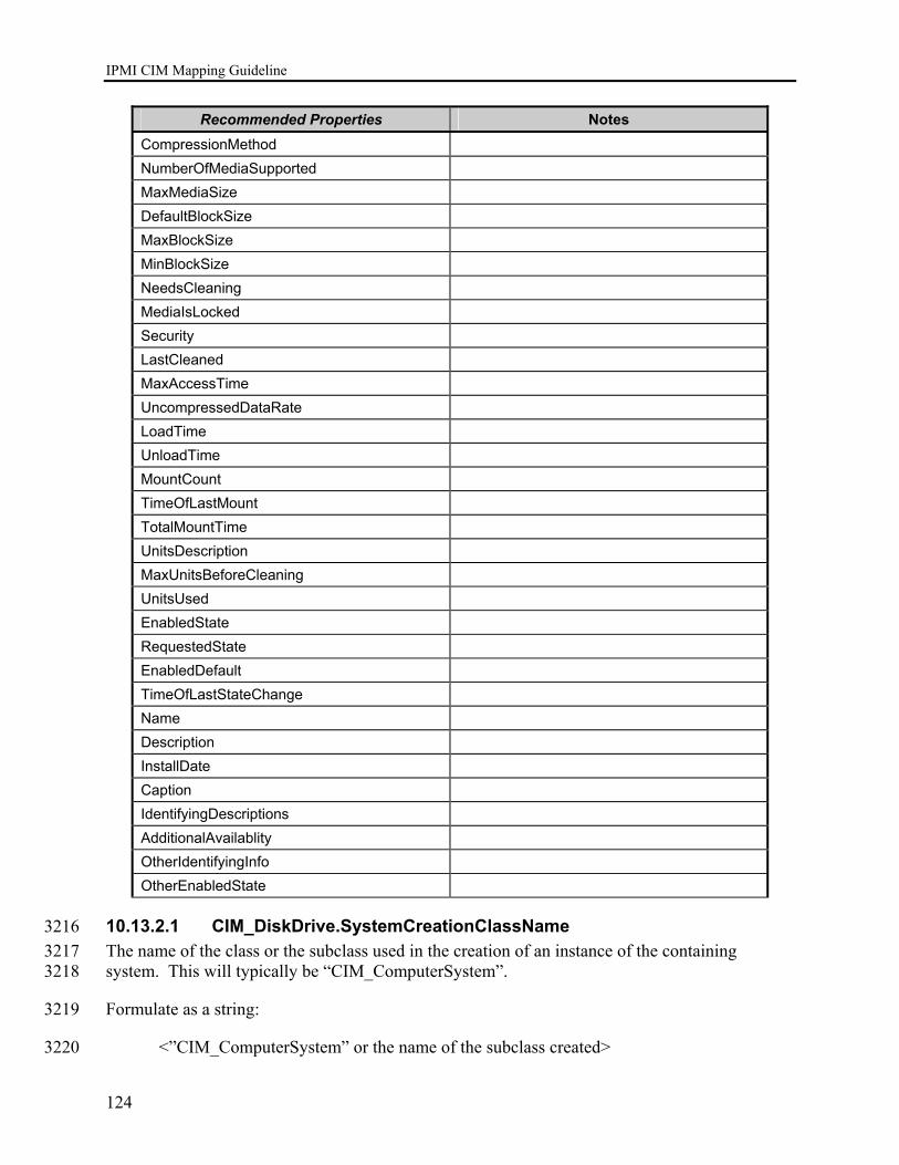
IPMI CIM Mapping Guideline
124
Recommended Properties Notes CompressionMethod NumberOfMediaSupported MaxMediaSize DefaultBlockSize MaxBlockSize MinBlockSize NeedsCleaning MediaIsLocked Security LastCleaned MaxAccessTime UncompressedDataRate LoadTime UnloadTime MountCount TimeOfLastMount TotalMountTime UnitsDescription MaxUnitsBeforeCleaning UnitsUsed EnabledState RequestedState EnabledDefault TimeOfLastStateChange Name Description InstallDate Caption IdentifyingDescriptions AdditionalAvailablity OtherIdentifyingInfo OtherEnabledState
10.13.2.1 CIM_DiskDrive.SystemCreationClassName 3216 The name of the class or the subclass used in the creation of an instance of the containing 3217 system. This will typically be “CIM_ComputerSystem”. 3218
Formulate as a string: 3219
<”CIM_ComputerSystem” or the name of the subclass created> 3220
IPMI CIM Mapping Guideline
125
3221
10.13.2.2 CIM_DiskDrive.CreationClassName 3222 Per the DMTF definition of the class property: The name of the class or the subclass used in the 3223 creation of an instance. This will typically be “CIM_DiskDrive”. 3224
Formulate as a string: 3225
<”CIM_DiskDrive” or the name of the subclass created> 3226
10.13.2.3 CIM_DiskDrive.SystemName 3227 The host name of the containing system. Derived from the CIM_ComputerSystem.Name 3228 property of the instance representing the containing system. 3229
Formulate as a string: 3230
<CIM_ComputerSystem.Name> 3231
10.13.2.4 CIM_DiskDrive.DeviceID 3232 Formulate as string: 3233
(string)<Entity ID from SDR> || “:” || (string)<Entity Instance from SDR> || “:” || 3234
|| (string)<Sensor Number from SDR> || “:” || <”DiskDrive”> 3235
10.13.2.5 CIM_DiskDrive.Description 3236 Formulate as string: 3237
“DiskDrive” || “(” || (string)(SensorNumber) || “.” || (string)(OwnerLUN) || “.” || 3238 string)(OwnerID) || “) ” || “ for ” || (string)(<IPMI_SDR_EntityID>) || “ “ || 3239 (string)(<IPMI_SDR_EntityInstanceNumber>) 3240
10.13.2.6 CIM_DiskDrive.ElementName 3241 Formulate as string: 3242
(string)< SDR entry bytes 49+, see IPMI v1.5 Table 37-1> || “(” || (string)<Entity ID from SDR> 3243 || “:” || (string)<Entity Instance from SDR> || “)” 3244
10.13.2.7 CIM_DiskDrive.HealthState 3245
10.13.2.8 CIM_DiskDrive.OperationalStatus 3246 3247

IPMI CIM Mapping Guideline
126
11 IPMI Watchdog Mapping 3248
11.1 Introduction 3249 The IPMI Watchdog Mapping extends the management capability of the IPMI to CIM mapping 3250 by adding the capability to manage the IPMI Watchdog 3251
The following class diagram describes the CIM classes involved in representing the IPMI 3252 watchdog. 3253
ComputerSystem
IPMI WatchdogClass Diagram
Watchdog
SystemDevice 3254
Figure 18 Class Diagram – IPMI Watchdog 3255
11.2 Instance Diagrams 3256 The following instance diagram describes an instance of CIM_Watchdog associated with the 3257 instance of CIM_ComputerSystem representing the BMC. 3258
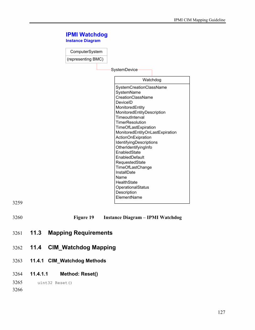
IPMI CIM Mapping Guideline
127
ComputerSystem
(representing BMC)
IPMI WatchdogInstance Diagram
Watchdog
SystemCreationClassNameSystemNameCreationClassNameDeviceIDMonitoredEntityMonitoredEntityDescriptionTimeoutIntervalTimerResolutionTimeOfLastExpirationMonitoredEntityOnLastExpirationActionOnExiprationIdentifyingDescriptionsOtherIdentifyingInfoEnabledStateEnabledDefaultRequestedStateTimeOfLastChangeInstallDateNameHealthStateOperationalStatusDescriptionElementName
SystemDevice
3259
Figure 19 Instance Diagram – IPMI Watchdog 3260
11.3 Mapping Requirements 3261
11.4 CIM_Watchdog Mapping 3262
11.4.1 CIM_Watchdog Methods 3263
11.4.1.1 Method: Reset() 3264
uint32 Reset() 3265 3266
IPMI CIM Mapping Guideline
128
Per the DMTF definition: The return value should be 0 if the request was successfully executed, 3267 1 if the request is not supported and some other value if an error occurred. This method should 3268 map to the IPMI Reset Watchdog Timer command. 3269 3270 A return value of 4 – Failed would indicate a Reset Watchdog Timer Command response data 3271 completion code of 80h meaning “Attempt to start an uninitialized watchdog” as indicated in 3272 IPMI v1.5 specification table 21-2. 3273
Return value: 3274 0 – Completed with no error 3275 1 – Not Supported 3276 2 – Unspecified Error 3277 3 – Timeout 3278 4 – Failed 3279 5 – Invalid Parameter 3280 6..0x0FFF – DMTF_Reserved 3281 0x1000..0x7FFF – Method_Reserved 3282 0x8000.. – Vendor_Reserved 3283
3284
11.4.1.2 Method: RequestStateChange 3285
uint32 RequestStateChange ( 3286 [IN] unit16 RequestedState, 3287 [IN] datetime TimeoutPeriod) 3288 3289
TimeoutPeriod maps to the Initial Countdown Value bytes for the Set Watchdog Timer 3290 command. RequestedState is not used; state changes can be performed by writing appropriate 3291 properties in the CIM_Watchdog class instance. 3292
Return value: 3293
0 – Completed with no error 3294 1 – Not Supported 3295 2 – Unspecified Error 3296 3 – Timeout 3297 4 – Failed 3298 5 – Invalid Parameter 3299 6..0x0FFF – DMTF_Reserved 3300 0x1000..0x7FFF – Method_Reserved 3301 0x8000.. – Vendor_Reserved 3302
3303
11.4.1.3 Method: KeepAlive 3304
uint32 KeepAlive() 3305 3306

IPMI CIM Mapping Guideline
129
A method to re-arm the timer. This method is only used if the MonitoredEntity is "Application". 3307 It returns 0 if successful, 1 if unsupported, and any other value if an error occurred. In an IPMI 3308 CIM mapping this will always return 1 – Not Supported. 3309
Return value: 3310
0 – Completed with no error 3311 1 – Not Supported 3312
11.4.2 CIM_Watchdog Properties 3313 REQUIRED properties are properties that MUST be present. RECOMMENDED properties are 3314 properties that MAY be present. For example, there may be properties that are only filled out in 3315 special configurations of the CIM Schema. 3316
Properties that are listed in the Required section in Table 6 below MUST be implemented as 3317 defined in the subsections following this table unless the Notes column for each property 3318 specifies the defining reference. 3319

IPMI CIM Mapping Guideline
130
Table 28 CIM_Watchdog Class Properties 3320
Required Properties Notes
SystemCreationClassName Key SystemName Key CreationClassName Key DeviceID Key MonitoredEntity MonitoredEntityDescription TimeoutInterval TimerResolution TimeOfLastExpiration MonitoredEntityOnLastExpiration ActionOnExpiration EnabledState DefaultState RequestedState Name OperationsStatus HealthState LogState Pending CR Approval in the DMTF ActionOnPretimeoutInterval Pending CR Approval in the DMTF PretimeoutInterval Pending CR Approval in the DMTF
3321 Recommended Properties Notes
OtherIndentifyingInfo IdentifyingDescriptions AdditionalAvailality OtherEnabledState TimeOfLastStateChange InstallDate Caption Description ElementName
3322
The following subsections describe procedures for generating values for various properties of 3323 CIM classes required in this profile. 3324
11.4.2.1 CIM_Watchdog.SystemCreationClassName 3325 The name of the class or the subclass used in the creation of an instance of the containing 3326 system. This will typically be “CIM_ComputerSystem”. 3327
IPMI CIM Mapping Guideline
131
Formulate as a string: 3328
<”CIM_ComputerSystem” or the name of the subclass created> 3329
11.4.2.2 CIM_Watchdog.SystemName 3330 The host name of the containing system. Derived from the CIM_ComputerSystem.Name 3331 property of the instance representing the containing system. 3332
Formulate as a string: 3333
<CIM_ComputerSystem.Name> 3334
11.4.2.3 CIM_Watchdog.CreationClassName 3335 Per the DMTF definition of the class property: The name of the class or the subclass used in the 3336 creation of an instance. This will typically be “CIM_Watchdog”. 3337
Formulate as a string: 3338
<”CIM_WatchDog” or the name of the subclass created> 3339
11.4.2.4 CIM_Watchdog.DeviceID 3340 Formulate as a string: 3341
An address or other identifying information to uniquely name the LogicalDevice. 3342
11.4.2.5 CIM_Watchdog.MonitoredEntity 3343 3344
Values { "Unknown" , "Other" , "Operating System" , "Operating System Boot Process" , 3345 "Operating System Shutdown Process" , "Firmware Boot Process" , "BIOS Boot Process" , 3346 "Application" , "Service Processor" } 3347
ValueMap { "0" , "1" , "2" , "3" , "4" , "5" , "6" , "7" , "8" } 3348
The entity that is currently being monitored by the WatchDog. This property is used to identify 3349 the module that is responsible for or whose information is used to re-arm the watchdog at 3350 periodic intervals. 3351
IPMI supported entities map to MonitoredEntity values as follows: 3352
001b BIOS FRB2 “6” "BIOS Boot Process" 010b BIOS POST “5” “Firmware Boot Process” 011b OS Load “3” “Operating System Boot Process” 100b SMS/OS “2” “Operating System” 101b OEM “1” “Other”

IPMI CIM Mapping Guideline
132
3353
MonitoredEntity values not listed above are not supported in this mapping. 3354
11.4.2.6 CIM_Watchdog.MonitoredEntityDecription 3355 Formulate as string: 3356
A string describing more textual information about the monitored entity: 3357
“BIOS FRB2”, “BIOS POST”, “OS Load”, “SMS/OS”, “OEM” 3358
11.4.2.7 CIM_Watchdog.TimeoutInterval 3359 3360 Units ( "MicroSeconds" ) 3361 3362 The timeout interval used by the watchdog, in MicroSeconds. 3363
11.4.2.8 CIM_Watchdog.TimerResolution 3364 3365 Units ( "MicroSeconds" ) 3366 3367 Resolution of the timer. For example, if this value is 100, then the timer can expire anytime 3368 between (TimeoutInterval- 100) microseconds or (TimeoutInterval+100) microseconds. 3369 3370 IPMI v1.5 Watchdog resolution is one count/100 milliseconds, or 100000 microseconds. The 3371 TimerResolution value will always map to 100000. 3372
11.4.2.9 CIM_Watchdog.TimeOfLastExpiration 3373 Datetime 3374 3375 The time of the last timer expiry. 3376
11.4.2.10 CIM_Watchdog.MonitoredEntityOnLastExpiration 3377 3378 Values { "Unknown" , "Other" , "Operating System" , "Operating System Boot Process" , 3379 "Operating System Shutdown Process" , "Firmware Boot Process" , "BIOS Boot Process" , 3380 "Application" , "Service Processor" } 3381 3382 ValueMap { "0" , "1" , "2" , "3" , "4" , "5" , "6" , "7" , "8" } 3383 3384 Monitored entity at the time of last timer expiry. 3385
IPMI supported entities map to MonitoredEntityOnLastExpiration values as follows: 3386
001b BIOS FRB2 “6” "BIOS Boot Process" 010b BIOS POST “5” “Firmware Boot Process”

IPMI CIM Mapping Guideline
133
011b OS Load “3” “Operating System Boot Process” 100b SMS/OS “2” “Operating System” 101b OEM “1” “Other” 3387
MonitoredEntityOnLastExpiration values not listed above are not supported in this mapping. 3388
11.4.2.11 CIM_Watchdog.ActionOnExpiration 3389 3390 Values { "None - Status Only" , "System Reset" , "System Power Off" , "System Power Off, then 3391 On" , "Generate System NonMaskableInterrupt (NMI)" , "Generate System Management 3392 Interrupt (SMI)" } 3393 3394 ValueMap { "0" , "1" , "2" , "3" , "4" , "5" } 3395 3396 The action that should happen upon the expiry of the watchdog. IPMI supports timeout actions 3397 as defined for bits [2:0] of the Set Watchdog Timer/Get Watchdog Timer commands’ Timer 3398 Action byte. These map directly to ActionOnExpiration values as follows: 3399 3400 000b No Action “0” “None – Status Only” 001b Hard Reset “1” “ System Reset” 010b Power Down “2” “System Power Off” 011b Power Cycle “3” “System Power Off, then On” 3401
Values “4” and “5” are not supported in this mapping. 3402
11.4.2.12 CIM_Watchdog.EnabledState 3403 3404 Values { "Unknown" , "Other" , "Enabled" , "Disabled" , "Shutting Down" , "Not Applicable" , 3405 "Enabled but Offline" , "In Test" , "Deferred" , "Quiesce" , "Starting" , "DMTF Reserved" , 3406 "Vendor Reserved" } 3407 3408 ModelCorrespondence { "CIM_EnabledLogicalElement.OtherEnabledState" } 3409 3410 ValueMap { "0" , "1" , "2" , "3" , "4" , "5" , "6" , "7" , "8" , "9" , "10" , "11..32767" , 3411 "32768..65535" } 3412 3413 EnabledState = 5 - Not Applicable (5) indicates the element doesn't support being 3414 enabled/disabled. 3415 3416
11.4.2.13 CIM_Watchdog.DefaultState 3417 Formulate as string: 3418
“” 3419
IPMI CIM Mapping Guideline
134
11.4.2.14 CIM_Watchdog.RequestedState 3420 3421 Values { "Enabled" , "Disabled" , "Shut Down" , "No Change" , "Offline" , "Test" , "Deferred" , 3422 "Quiesce" , "Reboot" , "Reset" , "Not Applicable" , "DMTF Reserved" , "Vendor Reserved" } 3423 3424 ModelCorrespondence { "CIM_EnabledLogicalElement.EnabledState" } 3425 3426 ValueMap { "2" , "3" , "4" , "5" , "6" , "7" , "8" , "9" , "10" , "11" , "12" , ".." , "32768..65535" } 3427 3428 RequestedState = 12 - Not supported 3429 3430 3431
11.4.2.15 CIM_Watchdog.Name 3432 Per the DMTF definition, the Name property defines the label by which the object is known. 3433 When subclassed, the Name property can be overridden to be a Key property. 3434
Formulate as string: 3435
“IPMI_WatchDog” 3436
11.4.2.16 CIM_Watchdog.OperationalStatus 3437 3438 Values { "Unknown" , "Other" , "OK" , "Degraded" , "Stressed" , "Predictive Failure" , "Error" , 3439 "Non-Recoverable Error" , "Starting" , "Stopping" , "Stopped" , "In Service" , "No Contact" , 3440 "Lost Communication" , "Aborted" , "Dormant" , "Supporting Entity in Error" , "Completed" , 3441 "Power Mode" , "DMTF Reserved" , "Vendor Reserved" } 3442 ModelCorrespondence { "CIM_ManagedSystemElement.StatusDescriptions" } 3443 ValueMap { "0" , "1" , "2" , "3" , "4" , "5" , "6" , "7" , "8" , "9" , "10" , "11" , "12" , "13" , "14" , 3444 "15" , "16" , "17" , "18" , ".." , "0x8000.." } 3445 ArrayType ( "Indexed" ) 3446 3447 Only the first element of OperationalStatus array is used in this mapping. OperationalStatus 3448 Values map to return states from the IPMI v1.5 Get Watchdog Timer command as follows: 3449 3450 Timer Use bit [6] = 1b “timer is started (running)” “2”, “OK” Timer Use bit [6] = 0b “timer is stopped” “10”, “Stopped” Error completion code from Get Watchdog Timer command “6”, “Error” No response from any Get Watchdog Timer command “12”, “No Contact” No response from most recent Get Watchdog Timer command
“13”, “Lost Communication”
3451
11.4.2.17 CIM_Watchdog.HealthState 3452 3453 Values { "Unknown" , "OK" , "Degraded/Warning" , "Minor failure" , "Major failure" , "Critical 3454

IPMI CIM Mapping Guideline
135
failure" , "Non-recoverable error" , "DMTF Reserved" } 3455 ValueMap { "0" , "5" , "10" , "15" , "20" , "25" , "30" , ".." } 3456 3457 “0” – Not supported 3458 3459
11.4.2.18 CIM_Watchdog.LogState 3460 3461 Values { "Unknown" , "Log" , "Do Not Log”} 3462 ValueMap { "0" , "1" , "2" } 3463 3464 Maps to Timer Use bit [7] indicating logging status for the watchdog 3465 3466
11.4.2.19 CIM_Watchdog.ActionOnPretimeoutInterval 3467 3468 Values { "None - Status Only" , "Generate System Management Interrupt (SMI)" , "Generate 3469 System NonMaskableInterrupt (NMI)" , "Messaging Interrupt" } 3470 3471 ValueMap { "0" , "1" , "2" , "3" } 3472 3473 The action that should happen when the pretimeout interval for the watchdog timer is passed. 3474 IPMI supports timeout actions as defined for bits [2:0] of the Set Watchdog Timer/Get Watchdog 3475 Timer commands’ Timer Action byte. These map to ActionOnPretimeoutInterval values as 3476 follows: 3477 3478 000b No Action “0” “None – Status Only” 001b SMI “1”, "Generate System Management Interrupt (SMI)" 010b NMI/Diagnostic Interrupt “2” “Generate System NonMaskableInterrupt (NMI)” 011b Messaging Interrupt “3” “Messaging Interrupt” 3479 3480
11.4.2.20 CIM_Watchdog.PretimeoutInterval 3481 3482 Units ( "Seconds" ) 3483 3484 The pretimeout interval used by the IPMI watchdog, in Seconds. 3485 3486
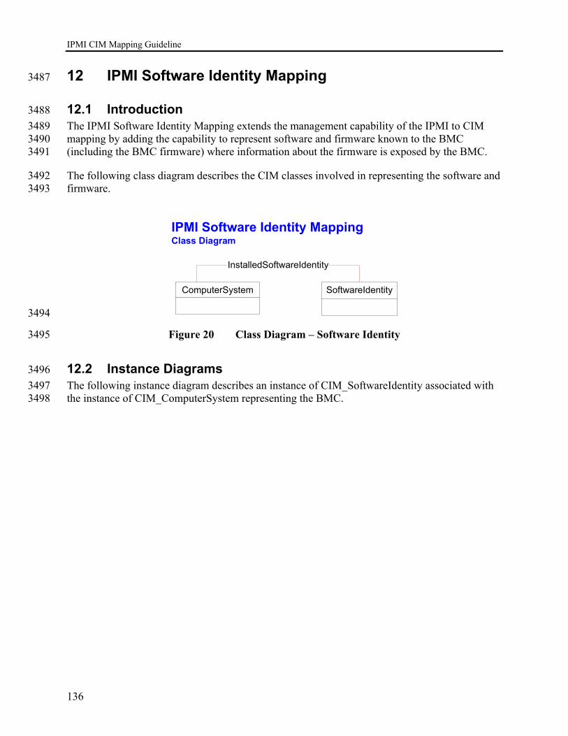
IPMI CIM Mapping Guideline
136
12 IPMI Software Identity Mapping 3487
12.1 Introduction 3488 The IPMI Software Identity Mapping extends the management capability of the IPMI to CIM 3489 mapping by adding the capability to represent software and firmware known to the BMC 3490 (including the BMC firmware) where information about the firmware is exposed by the BMC. 3491
The following class diagram describes the CIM classes involved in representing the software and 3492 firmware. 3493
IPMI Software Identity MappingClass Diagram
ComputerSystem
InstalledSoftwareIdentity
SoftwareIdentity
3494
Figure 20 Class Diagram – Software Identity 3495
12.2 Instance Diagrams 3496 The following instance diagram describes an instance of CIM_SoftwareIdentity associated with 3497 the instance of CIM_ComputerSystem representing the BMC. 3498
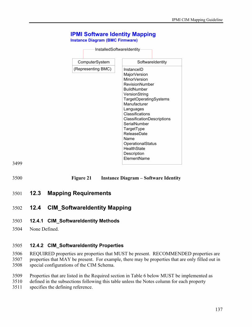
IPMI CIM Mapping Guideline
137
IPMI Software Identity Mapping Instance Diagram (BMC Firmware)
ComputerSystem
(Representing BMC)
InstalledSoftwareIdentity
SoftwareIdentity
InstanceIDMajorVersionMinorVersionRevisionNumberBuildNumberVersionStringTargetOperatingSystemsManufacturerLanguagesClassificationsClassificationDescriptionsSerialNumberTargetTypeReleaseDateNameOperationalStatusHealthStateDescriptionElementName
3499
Figure 21 Instance Diagram – Software Identity 3500
12.3 Mapping Requirements 3501
12.4 CIM_SoftwareIdentity Mapping 3502
12.4.1 CIM_SoftwareIdentity Methods 3503 None Defined. 3504
12.4.2 CIM_SoftwareIdentity Properties 3505 REQUIRED properties are properties that MUST be present. RECOMMENDED properties are 3506 properties that MAY be present. For example, there may be properties that are only filled out in 3507 special configurations of the CIM Schema. 3508
Properties that are listed in the Required section in Table 6 below MUST be implemented as 3509 defined in the subsections following this table unless the Notes column for each property 3510 specifies the defining reference. 3511
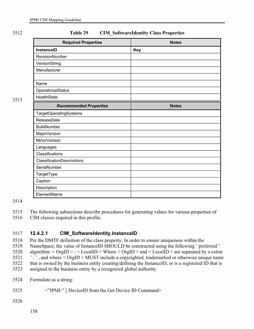
IPMI CIM Mapping Guideline
138
Table 29 CIM_SoftwareIdentity Class Properties 3512
Required Properties Notes
InstanceID Key RevisionNumber VersionString Manufacturer Name OperationalStatus HealthState
3513 Recommended Properties Notes
TargetOperatingSystems ReleaseDate BuildNumber MajorVersion MinorVersion Languages Classifications ClassificationDescriotions SerialNumber TargetType Caption Description ElementName
3514
The following subsections describe procedures for generating values for various properties of 3515 CIM classes required in this profile. 3516
12.4.2.1 CIM_SoftwareIdentity.InstanceID 3517 Per the DMTF definition of the class property: In order to ensure uniqueness within the 3518 NameSpace, the value of InstanceID SHOULD be constructed using the following ’ preferred ’ 3519 algorithm: < OrgID > : < LocalID > Where < OrgID > and < LocalID > are separated by a colon 3520 ’ : ’ , and where < OrgID > MUST include a copyrighted, trademarked or otherwise unique name 3521 that is owned by the business entity creating/defining the InstanceID, or is a registered ID that is 3522 assigned to the business entity by a recognized global authority. 3523
Formulate as a string: 3524
<”IPMI:” || DeviceID from the Get Device ID Command> 3525
3526

IPMI CIM Mapping Guideline
139
12.4.2.2 CIM_SoftwareIdentity.RevisionNumber 3527 Per the DMTF definition of the class property: This property is defined as a numeric value to 3528 allow the determination of ’ newer ’ vs. ’ older ’ releases. A ’ newer ’ revision is indicated by a 3529 larger numeric value. 3530
Formulate as a string: 3531
<Firmware Revision 1 from the Get Device ID Command || “.” 3532
|| Firmware Revision 2 from the Get Device ID Command> 3533
12.4.2.3 CIM_SoftwareIdentity.VersionString 3534 Per the DMTF definition of the class property: A string representing the complete software 3535 version information. 3536
Formulate as a string: 3537
<<Firmware Revision 1 from the Get Device ID Command || “.” 3538
|| Firmware Revision 2 from the Get Device ID Command || “.” 3539
|| Auxillary Firmware Revision Information from the Get Device ID Command> 3540
12.4.2.4 CIM_SoftwareIdentity.Manufacturer 3541 Per the DMTF definition of the class property: Manufacturer of this software. 3542
Formulate as a string: 3543
<<Manufacturer ID from the Get Device ID Command> 3544
12.4.2.5 CIM_SoftwareIdentity.Name 3545 Formulate as a string: 3546
< “IPMI BMC Firmware “ || 3547
|| Firmware Revision 1 from the Get Device ID Command || “.” 3548
|| Firmware Revision 2 from the Get Device ID Command> 3549
12.4.2.6 CIM_SoftwareIdentity.OperationalStatus 3550
12.4.2.7 CIM_SoftwareIdentity.HealthState 3551 3552 3553

IPMI CIM Mapping Guideline
140
13 Acknowledgments 3554 Editor 3555
Jon Hass - Dell Inc. for the IPMI CIM Subcommittee of the IPMI Forum 3556
3557
Contributors 3558
Jon Hass - Dell Inc. 3559
Steffen C. Hulegaard - OSA Inc. 3560
Frank Li – OSA Inc. 3561
Arvind Kumar – Intel Corporation 3562
Tom Slaight - Intel Corporation 3563
Wayne Weilnau – Dell Inc. 3564
Chandra Mugunda – Dell Inc. 3565
Phil Chidester - Dell Inc. 3566
Steve Lyle – Hewlett-Packard Company 3567
Kevin Howard – Hewlett-Packard Company 3568
3569
End of Document 3570