ipmcs as eaps: how to start experimenting with them · connecting with other materials can also be...
TRANSCRIPT
IPMCs as EAPs: How to Start Experimentingwith Them
Kinji Asaka, Karl Kruusam€ae, Kwang Kim, Viljar Palmre, andKam K. Leang
Contents1 Fabrication of IPMC . . . . . . . . . . . . . . . . . . . . . . . . . . . . . . . . . . . . . . . . . . . . . . . . . . . . . . . . . . . . . . . . . . . . . . . . . . 2
1.1 Ionic Polymer . . . . . . . . . . . . . . . . . . . . . . . . . . . . . . . . . . . . . . . . . . . . . . . . . . . . . . . . . . . . . . . . . . . . . . . . . . . 21.2 Electrode Plating . . . . . . . . . . . . . . . . . . . . . . . . . . . . . . . . . . . . . . . . . . . . . . . . . . . . . . . . . . . . . . . . . . . . . . . . 31.3 Fabrication of Actuator Devices . . . . . . . . . . . . . . . . . . . . . . . . . . . . . . . . . . . . . . . . . . . . . . . . . . . . . . . 4
2 Electromechanical Characterization of IPMCs . . . . . . . . . . . . . . . . . . . . . . . . . . . . . . . . . . . . . . . . . . . . . . 52.1 Considerations for the Experimental Setup . . . . . . . . . . . . . . . . . . . . . . . . . . . . . . . . . . . . . . . . . . . . 52.2 Representing Experimental Results . . . . . . . . . . . . . . . . . . . . . . . . . . . . . . . . . . . . . . . . . . . . . . . . . . . . 82.3 Reporting the Electromechanical Response . . . . . . . . . . . . . . . . . . . . . . . . . . . . . . . . . . . . . . . . . . . 10
3 Implementation and Control of IPMCs . . . . . . . . . . . . . . . . . . . . . . . . . . . . . . . . . . . . . . . . . . . . . . . . . . . . . . 103.1 IPMC Actuators for Creating Complex Deformations . . . . . . . . . . . . . . . . . . . . . . . . . . . . . . . . 123.2 Feedforward and Feedback Control for Mitigating IPMC Back Relaxation . . . . . . . . . . 13
4 Conclusion . . . . . . . . . . . . . . . . . . . . . . . . . . . . . . . . . . . . . . . . . . . . . . . . . . . . . . . . . . . . . . . . . . . . . . . . . . . . . . . . . . . . 17References . . . . . . . . . . . . . . . . . . . . . . . . . . . . . . . . . . . . . . . . . . . . . . . . . . . . . . . . . . . . . . . . . . . . . . . . . . . . . . . . . . . . . . . . 18
K. Asaka (*)Inorganic Functional Material Research Institute, National Institute of Advanced Industrial Scienceand Technology (AIST), Ikeda, Osaka, Japane-mail: [email protected]
K. Kruusam€aeDepartment of Mechanical Engineering, University of Texas at Austin, Austin, USAe-mail: [email protected]
K. Kim • V. PalmreDepartment of Mechanical Engineering, University of Nevada, Las Vegas, NV, USAe-mail: [email protected]; [email protected]
K.K. LeangDepartment of Mechanical Engineering, University of Utah, Salt Lake City, UT, USAe-mail: [email protected]
# Springer International Publishing Switzerland 2016F. Carpi (ed.), Electromechanically Active Polymers, Polymers and PolymericComposites: A Reference Series, DOI 10.1007/978-3-319-31767-0_10-1
1
AbstractThis chapter describes how to start experiments with ionic polymer–metalcomposite (IPMC) actuators. In the first part, a fabrication of IPMC actuatorelement is summarized. In the next part, how to setup a measurement system ofIPMC actuator and test the actuator performance is described. In the last part, acontrol method of IPMC actuator is discussed. From the information in thischapter, experiments with IPMC actuators can be started.
KeywordsIonic polymer-metal composite (IPMC) • Ionic polymer • Electroplating • Elec-tromechanical characterization • Control method
1 Introduction
In this chapter, how to start experiments with IPMC actuators in order to apply themto various applications as shown in the previous chapters are described. In order forthat, how to fabricate IPMC actuator elements, how to set up a measurement systemof IPMC actuator and test the actuator performance, and a control method of IPMCactuator are described in this chapter.
2 Fabrication of IPMC
As shown in the previous chapters, an ionic polymer–metal composite (IPMC) iscomposed of an ionic polymer plated with metal electrodes. By deforming the ionicpolymer and patterning the plated electrodes, soft actuator devices that are capable ofmoving in multiple degrees of freedom can be fabricated.
In the first part of this section of starting experiments with IPMC actuator, basicsof ionic polymer used for IPMC, electroplating method, and fabrication of IPMC
-(CF2-CF2)n-(CF-CF2)- -(CF2-CF2)n-(CF-CF2)-
O
CF2 CF2
(CF2)2 (CF2)3
COO-M+SO3-M+
O O
O
CF-CF3 CF-CF3
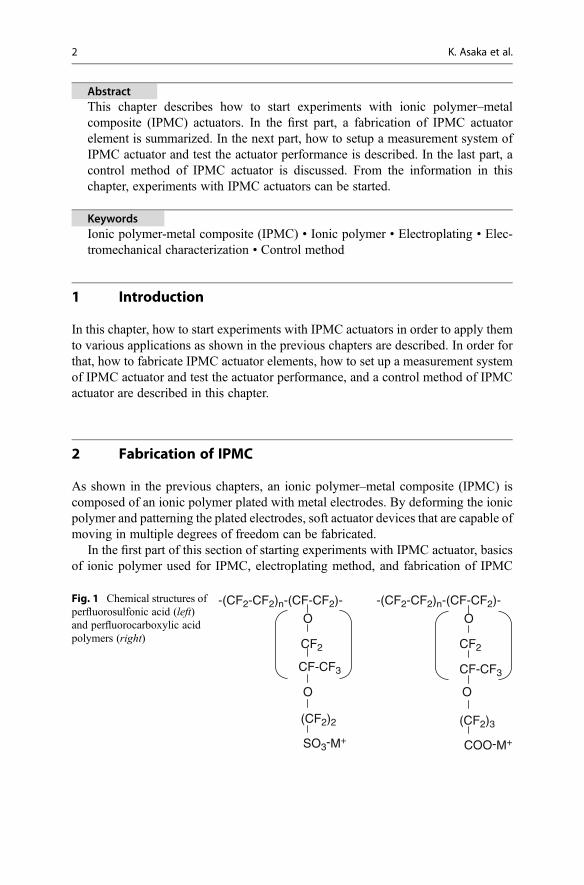
Fig. 1 Chemical structures ofperfluorosulfonic acid (left)and perfluorocarboxylic acidpolymers (right)
2 K. Asaka et al.

device including deforming ionic polymer and patterning electrode are described.Since details of ionic polymers and plating methods are described in the precedingchapters, this part describes only a summary of them.
2.1 Ionic Polymer
For IPMCs, their performances critically depend on ionic polymer used. Ionicpolymers usually used for the IPMC are perfluorosulfonic acid or perfluoro-carboxylic acid polymers, of which the typical chemical structures are shown inFig. 1. One can obtain various types of thin films made from perfluorosulfonic acidfrom E. I. du Pont de Nemours and Company as commercial products (Nafion).Other several companies supply similar compounds. Asahi Glass Co., Ltd. producesperfluorocarboxylic acid type polymer films (Flemion).
Hydration of the perfluorinated ionic polymers (PIPs) depends on the ionicform and ion-exchange capacity (Asaka et al. 2001). In the case of the Nafionmembrane, the water content decreases with the increase in the hydrophobicityof the counter cation. The ionic conductivity also depends on the ionic size, thehydration, the charge density of the ionic polymer, etc. For instance, the alkalication-form and alkaline earth cation-form PIPs have larger conductivity thanalkyl ammonium cation-form PIPs. Increasing the size of the alkyl ammoniumcation decreases the conductivity. These results are closely related on theion-cluster structure of the PIP.
It is well-known that the PIP swelled with water has a hydrophilic channel-linked ion-cluster structure surrounding with hydrophobic perfluoro-backbonepolymer network (Yeo and Yeager 1985). Counterions and water transfer throughhydrophilic narrow channel-linked ion cluster. If hydrophilic small cations suchas Li+, Na+, K+, etc. transfer through the channel, large mobility (high ionicconductivity) and little water drag take place, which result in higher response andsmaller displacement of the actuation of the IPMC. The opposite is true in thecase of hydrophobic large cations such as TEA+ and TBA+ (Onishi et al. 2001a).In other words, the actuation performance of the IPMC can be controlled bychanging counter cation species in the PIP, which can be easily changed byimmersing the IPMC in electrolyte solution for more than one night. The detailsof the behavior of the IPMC actuation response of various ionic forms can bedescribed by recent improvement in multi-physical modeling (Yamaueet al. 2005; Zhu et al. 2013a, b) of IPMC actuation based on ion-cluster structureof ionic polymer.
The perfluorinated ionic polymers are still the best ionic polymers for the IPMC.However, these polymers have some limitations, especially their high cost forapplications. Therefore, recently, various hydrocarbon-based ionic polymers forthe IPMC have been developed (Jo et al. 2013).
IPMCs as EAPs: How to Start Experimenting with Them 3

2.2 Electrode Plating
An established method of the electroplating on the ionic polymers is a chemicalplating method using platinum or gold electrodes. Details are described in thepreceding chapters.
After roughening the surface of the ionic polymer by dry blasting or emery paper,the ionic polymer is immersed in the aqueous solution of a metal complex salt. Then,the metal complex adsorbed in the ionic polymer is reduced by the reducing agent.The sequential plating technique has been developed for optimizing the electrodestructure, which has large electrochemical area and soft mechanical property (Onihsiet al. 2001b). Figure 2 shows the photograph of the gold-plated IPMC.
Recently, the electroplating methods of nanoparticles of other metals, metaloxides, or carbons including several physical technologies such as their printing orpressing were developed (Akle et al. 2006; Palmre et al. 2009).
2.3 Fabrication of Actuator Devices
In order to fabricate the IPMC actuator device, forming the ionic polymer andpatterning the plating electrodes are often needed. Forming the fluorinatedion-exchange polymer can be easily done by casting the dispersing solution andevaporating the solvent or hot molding the thermoplastic resin and activating theionic polymer by hydrolysis. Preparing the ionic polymer of various shapes andconnecting with other materials can also be done by the same method (Asaka andOguro 2009).
In order to make an IPMC device that can move in multiple degrees of freedom,the plating electrodes need to be patterned. In the laboratory, the plating electrode
Fig. 2 Photograph of a gold-plated Nafion IPMC
4 K. Asaka et al.
can be patterned by cutting the plating electrode by PC-controlled mechanical oroptical (laser) cutting machine (Asaka and Oguro 2009). The details on the fabrica-tion of IPMC actuator devices including forming and patterning electrodes forcomplex motions will be described in the Sect. 10.3.
As mentioned previously, the actuation performances such as response speed,displacement amplitude, back relaxation, etc. can be controlled by changing countercations. In order for this to happen, an IPMC element is immersed in the concen-trated electrolyte solution (more than 0.1 mol/l) of the desired dopant cation.
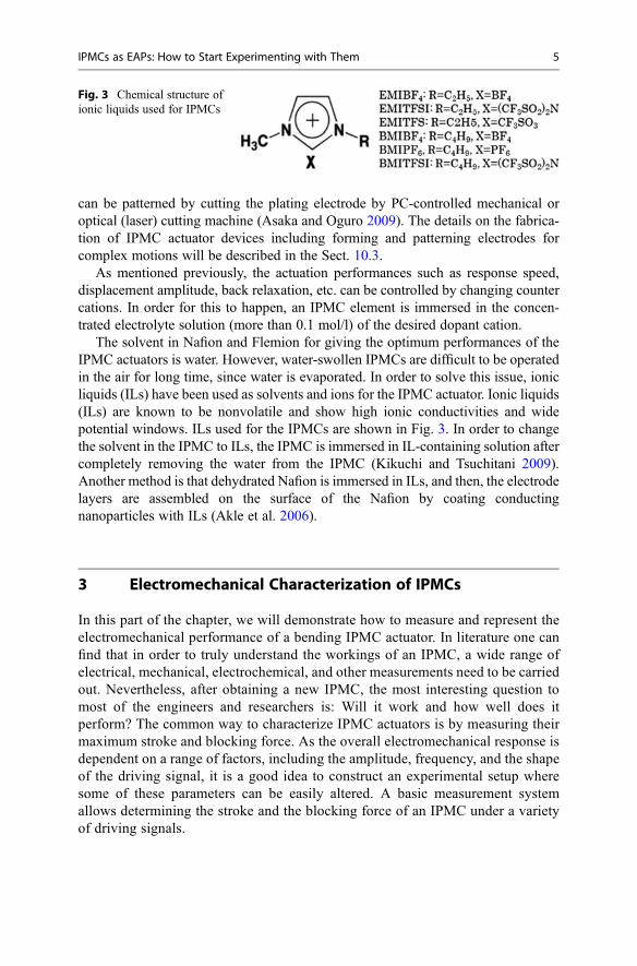
The solvent in Nafion and Flemion for giving the optimum performances of theIPMC actuators is water. However, water-swollen IPMCs are difficult to be operatedin the air for long time, since water is evaporated. In order to solve this issue, ionicliquids (ILs) have been used as solvents and ions for the IPMC actuator. Ionic liquids(ILs) are known to be nonvolatile and show high ionic conductivities and widepotential windows. ILs used for the IPMCs are shown in Fig. 3. In order to changethe solvent in the IPMC to ILs, the IPMC is immersed in IL-containing solution aftercompletely removing the water from the IPMC (Kikuchi and Tsuchitani 2009).Another method is that dehydrated Nafion is immersed in ILs, and then, the electrodelayers are assembled on the surface of the Nafion by coating conductingnanoparticles with ILs (Akle et al. 2006).
3 Electromechanical Characterization of IPMCs
In this part of the chapter, we will demonstrate how to measure and represent theelectromechanical performance of a bending IPMC actuator. In literature one canfind that in order to truly understand the workings of an IPMC, a wide range ofelectrical, mechanical, electrochemical, and other measurements need to be carriedout. Nevertheless, after obtaining a new IPMC, the most interesting question tomost of the engineers and researchers is: Will it work and how well does itperform? The common way to characterize IPMC actuators is by measuring theirmaximum stroke and blocking force. As the overall electromechanical response isdependent on a range of factors, including the amplitude, frequency, and the shapeof the driving signal, it is a good idea to construct an experimental setup wheresome of these parameters can be easily altered. A basic measurement systemallows determining the stroke and the blocking force of an IPMC under a varietyof driving signals.
Fig. 3 Chemical structure ofionic liquids used for IPMCs
IPMCs as EAPs: How to Start Experimenting with Them 5
3.1 Considerations for the Experimental Setup
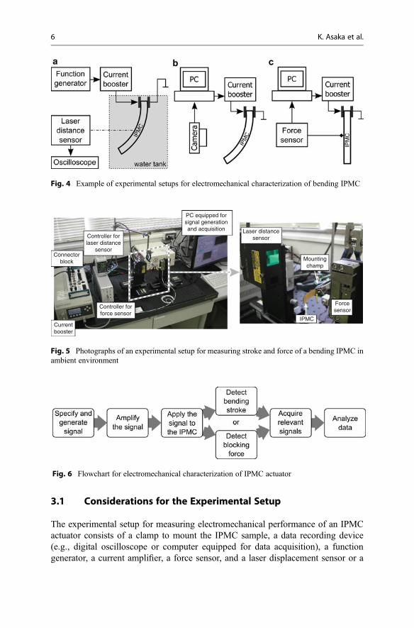
The experimental setup for measuring electromechanical performance of an IPMCactuator consists of a clamp to mount the IPMC sample, a data recording device(e.g., digital oscilloscope or computer equipped for data acquisition), a functiongenerator, a current amplifier, a force sensor, and a laser displacement sensor or a
Fig. 4 Example of experimental setups for electromechanical characterization of bending IPMC
PC equipped forsignal generationand acquisition
Controller forlaser distance
sensorConnector
block
Controller forforce sensor
Currentbooster
Laser distancesensor
Mountingchamp
IPMC
Forcesensor
Fig. 5 Photographs of an experimental setup for measuring stroke and force of a bending IPMC inambient environment
Fig. 6 Flowchart for electromechanical characterization of IPMC actuator
6 K. Asaka et al.
video camera (Figs. 4 and 5). The process diagram of electromechanical character-ization is given in Fig. 6.
The role of the mounting clamp is to position the actuator in a cantileverconfiguration while also acting as an outlet for driving voltage. Because IPMCscontain solvent such as water or ionic liquid that may leak out, it is better to use noblemetal (such as gold) for electric contacts to avoid oxidation or any other kind ofdeterioration of conductivity. The pressure of clamping has been reported to influ-ence the performance of IPMC (Moeinkhah et al. 2013); thus, it is recommended tohave some control over it. Moreover, for minimizing the influence of gravitationalforce on the performance of the actuator, it is practical to position the IPMC so thatthe bending occurs in the horizontal plane (e.g., Fig. 5).
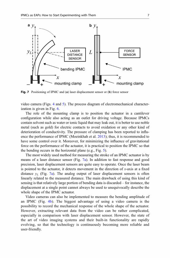
The most widely used method for measuring the stroke of an IPMC actuator is bymeans of a laser distance sensor (Fig. 7a). In addition to fast response and goodprecision, laser displacement sensors are quite easy to operate. Once the laser beamis pointed to the actuator, it detects movement in the direction of x-axis at a fixeddistance yL (Fig. 7a). The analog output of laser displacement sensors is oftenlinearly related to the measured distance. The main drawback of using this kind ofsensing is that relatively large portion of bending data is discarded – for instance, thedisplacement at a single point cannot always be used to unequivocally describe thewhole shape of the IPMC actuator.
Video cameras can also be implemented to measure the bending amplitude ofan IPMC (Fig. 4b). The biggest advantage of using a video camera is thepossibility to record the mechanical response of the whole shape of the actuator.However, extracting relevant data from the video can be rather complicated,especially in comparison with laser displacement sensor. However, the state ofthe art of video imaging systems and their built-in functionality are rapidlyevolving, so that the technology is continuously becoming more reliable anduser-friendly.
Fig. 7 Positioning of IPMC and (a) laser displacement sensor or (b) force sensor
IPMCs as EAPs: How to Start Experimenting with Them 7
Since many IPMCs operate best in water, it may be necessary to submerge theIPMC sample in a tank of deionized water during the electromechanical measure-ments (Fig. 4a). As cameras and displacement sensors remain outside the tank,parallelepiped water tank is recommended to minimize uncertainty due to opticaldistortions.
Blocking force of an IPMC can be determined by using a load cell with suitableoperating range. As the measured forces are typically in the range of millinewtons,even the slightest vibrations can affect the experimental results.
The driving signals are usually specified and created by using a dedicatedfunction generator or a PC with appropriate software and hardware (e.g., NationalInstruments LabVIEW with a suitable interface device). For amplifying the driv-ing signal, a potentiostat or a custom-made conditioning circuit can be used. Thepeak current consumption of an IPMC is dependent on the material properties aswell as the dimensions of the actuator sample. For instance, a water-based IPMCwith Na+ cations and dimensions of 50 � 10 � 0.2 mm can show peak currentconsumption over 1 A under rectangular input signal with amplitude of 2 V(Anton et al. 2008). There is no convention about which type of driving signalto prefer when characterizing IPMC actuators, but rectangular and sinusoidal areused most often.
The input voltage must take into account the electrochemical window of thesolvent used in a particular IPMC. Typically 1–2 V is sufficient to observenoteworthy actuation response without any decomposition. Even though thresholdvoltage for water electrolysis is about 1.23 V, higher input voltages can be appliedto a water-based IPMC as the potential between the electrode layers of an IPMCremains below that level. It is quite challenging to precisely determine the upperlimits for input voltage but closely observing the behavior of current can help toidentify the presence of undesired electrochemical processes. For experimentscarried out inside a water tank, the use of too high input voltage can result in the
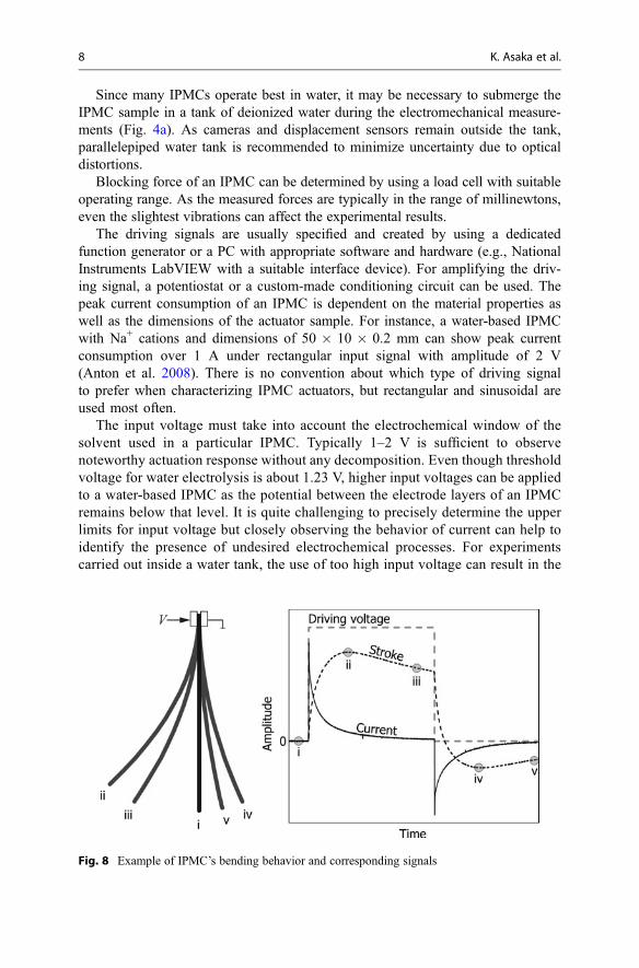
Fig. 8 Example of IPMC’s bending behavior and corresponding signals
8 K. Asaka et al.

production of oxyhydrogen which in turn can lead to a catastrophic failure of thesystem.
3.2 Representing Experimental Results
Figure 8 depicts an example of signals acquired when characterizing an IPMCactuator.
In Fig. 8 the stroke of a cantilever actuator is given in terms of the displacementx at a constant distance yL (Fig. 7a). Whereas this kind of time domain plots is highlyinformative, in order to manage large quantities of data, one might select a singlenumber, such as the maximum displacement value (xmax), to describe the perfor-mance of the actuator under a particular input signal. However, in addition to theproperties of the actuator and parameters of the input signal, the (maximum)displacement value is dependent on the geometry of the experimental setup, espe-cially on the distance yL.
One way to overcome the dependency to geometry is to assume uniform (i.e.,circular) curvature of the actuator during its work cycle. In this case, the actuation isexpressed as the curvature κ or bend radius r = κ�1 of the sample. If the curvature isobtained using a video camera or a laser profilometer, it can provide an accuratedescription for the overall shape of the actuator. However, if the curvature iscalculated from the displacement x using the well-known geometrical relationsgiven in Eq. 1, the results may be biased. Since an IPMC can be regarded to behavelike a transmission line, its curvature is often larger at smaller values of yL (Punninget al. 2009; Vunder et al. 2012; Kruusam€ae et al. 2014):
κ ¼ 2x
yL2 þ x2
)x�rκ � 2x
y2L(1)
In the cases of actuator exhibiting a complex behavior of bending or its initial shapecannot be accurately described by a circular curve, a more general approach thatdivides the length of an actuator into vectors of equal length has been proposed(Punning et al. 2009; Vunder et al. 2012). Each vector is described by its angle
Fig. 9 Vector-based representation of a bending actuator
IPMCs as EAPs: How to Start Experimenting with Them 9
relative to the previous vector (Fig. 9), thus allowing representations of a largevariety of shapes. The accuracy of such representation is determined by the numberof vectors used to describe the IPMC.
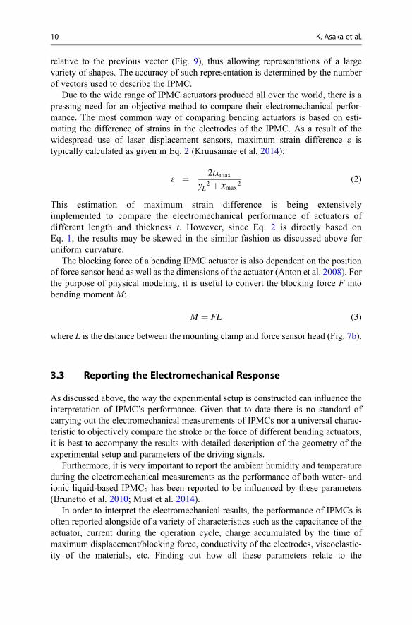
Due to the wide range of IPMC actuators produced all over the world, there is apressing need for an objective method to compare their electromechanical perfor-mance. The most common way of comparing bending actuators is based on esti-mating the difference of strains in the electrodes of the IPMC. As a result of thewidespread use of laser displacement sensors, maximum strain difference e istypically calculated as given in Eq. 2 (Kruusam€ae et al. 2014):
e ¼ 2txmax
yL2 þ xmax
2(2)
This estimation of maximum strain difference is being extensivelyimplemented to compare the electromechanical performance of actuators ofdifferent length and thickness t. However, since Eq. 2 is directly based onEq. 1, the results may be skewed in the similar fashion as discussed above foruniform curvature.
The blocking force of a bending IPMC actuator is also dependent on the positionof force sensor head as well as the dimensions of the actuator (Anton et al. 2008). Forthe purpose of physical modeling, it is useful to convert the blocking force F intobending moment M:
M ¼ FL (3)
where L is the distance between the mounting clamp and force sensor head (Fig. 7b).
3.3 Reporting the Electromechanical Response
As discussed above, the way the experimental setup is constructed can influence theinterpretation of IPMC’s performance. Given that to date there is no standard ofcarrying out the electromechanical measurements of IPMCs nor a universal charac-teristic to objectively compare the stroke or the force of different bending actuators,it is best to accompany the results with detailed description of the geometry of theexperimental setup and parameters of the driving signals.
Furthermore, it is very important to report the ambient humidity and temperatureduring the electromechanical measurements as the performance of both water- andionic liquid-based IPMCs has been reported to be influenced by these parameters(Brunetto et al. 2010; Must et al. 2014).
In order to interpret the electromechanical results, the performance of IPMCs isoften reported alongside of a variety of characteristics such as the capacitance of theactuator, current during the operation cycle, charge accumulated by the time ofmaximum displacement/blocking force, conductivity of the electrodes, viscoelastic-ity of the materials, etc. Finding out how all these parameters relate to the
10 K. Asaka et al.

electromechanical response of IPMCs is a subject of ongoing research in the field ofelectroactive polymers.
4 Implementation and Control of IPMCs
While the previous sections of this chapter concern the experimental testing andcharacterization of IPMCs, the following section describes how to implement andcontrol the IPMC actuators in specific robotic designs and applications. IPMCs arehighly regarded for biomimetic underwater systems, such as autonomous oceanmapping and surveillance robots that move through their environment by imitatingthe swimming motion of aquatic animals. However, in order to emulate the behaviorof even the simplest of these organisms, the robotic control surfaces must enablemultiple degrees of freedom motion. This section describes how to utilize andcontrol the IPMC actuators to create complex deformations such as bending, twist-ing, flapping, and other bioinspired motion for robotic applications. The approachesdiscussed include patterning the surface electrodes and selectively activating thespecific sectors or, alternatively, incorporating IPMC actuators into a soft bootmaterial for creating a control surface. In addition, the feedforward and feedbackcontrol method for mitigating the back relaxation of IPMC by controlled activationof sectored electrodes is presented.
4.1 IPMC Actuators for Creating Complex Deformations
IPMC strip actuators are conventionally used in the cantilever configuration togenerate a bending motion for propulsion of underwater robotic systems. However,this approach creates a simple 1D bending motion and performance is rather limited.To enable more complex multiple degrees of freedom motion, such as twisting,IPMCs with patterned (sectored) electrodes have been designed (Hubbardet al. 2014). Patterning of IPMC electrodes can be done after plating process usinga computer-controlled milling machine equipped with a microsurface routing endmill (Kim et al. 2011). The end mill, rotating ~3000 rev/min, is programmed tofollow a predefined trajectory that defines the electrode pattern. The end millremoves the necessary metal down to a membrane surface, creating a monolithicIPMC with isolated electrodes, as shown in Fig. 10. Figure 10a shows the typicalexperimental setup with two laser displacement sensors to measure the bending andtwisting motion of patterned IPMC.
For the monolithic IPMC with four isolated electrode pads (Fig. 10), the twistingmotion is produced by phase shifting the input signal between the left and rightsectors. In the case of 180� phase shifting, the patterned IPMC can achieve themaximum twist angle of 8.46� at 4 V DC input. The twist angle increases signifi-cantly with increasing input voltage as well as decreasing actuation frequency(sinusoidal input). These trends are shown in Fig. 11, demonstrating the ability ofmonolithic IPMC to generate practical twisting motion.
IPMCs as EAPs: How to Start Experimenting with Them 11

Fig. 10 (a) Experimental setup for measuring bending/twisting response for (b) an examplepatterned IPMC (units in mm) (# 2014 IEEE. Reprinted, with permission, from Hubbardet al. (2014) Monolithic IPMC fins for propulsion and maneuvering in bioinspired underwaterrobotics. IEEE J Ocean Eng 39(3):540–551)
Fig. 11 (a) Twist angle of IPMC versus amplitude of DC input voltage and (b) twist angle versusinput signal frequency (sinusoidal input) (# 2014 IEEE. Reprinted, with permission, from Hubbardet al. (2014) Monolithic IPMC fins for propulsion and maneuvering in bioinspired underwaterrobotics. IEEE J Ocean Eng 39(3):540–551)
12 K. Asaka et al.

An alternative approach for producing complex bioinspired motion involvesintegrating IPMC actuators into a soft silicone material to create an active controlsurface, called a “fin” (see Fig. 12) (Palmre et al. 2013). The fin can be used toachieve complex deformation depending on the placement and orientation of theactuator strips. In contrast to the monolithic IPMCs with patterned electrodesdescribed earlier, this design approach does not require (1) the expensive processof electroless plating platinum all throughout the actuator surface and (2) specially
Fig. 13 Two views showing the maximum twist angle achieved at 4 V square-wave input. Bottom:the input voltage and the time of maximum deflection noted by the red dotted line (Palmreet al. 2013) (# IOP Publishing. Reproduced with permission from IOP Publishing. All rightsreserved)
Fig. 12 (a) IPMCs integrated into soft boot structure illustrating bending and twisting motion byselectively activating electrodes and (b) example soft bioinspired robotic platform with embeddedIPMC actuators (Palmre et al. 2013) (# IOP Publishing. Reproduced with permission from IOPPublishing. All rights reserved)
IPMCs as EAPs: How to Start Experimenting with Them 13
machining (patterning) the electrodes. Therefore, conventional IPMC actuators suchas those with rectangular shapes can be used. The unique advantage of this structuraldesign is that custom shaped fins and control surfaces can be easily fabricatedwithout special materials processing. The molding process of silicone rubber isrelatively inexpensive and does not require functionalizing or “activating” the bootmaterial as in case of preparing IPMCs.
Figure 13 shows three IPMC actuator strips embedded in a soft silicone structure.The twisting motion is produced by phase shifting the same input signal by 180�
between the outer two IPMCs. The center IPMC is not actuated in order to notobstruct the movement of either adjacent IPMCs. A square-wave signal of 4 V at50 mHz was applied to drive the boot-IPMC. As shown in Fig. 13, the maximumtwist angle measured at this input is approximately 12�. Photographs indicate thatdue to the flexible boot structure, a complex shape is produced so that the anglevaries both along the length and height of the control surface.
4.2 Feedforward and Feedback Control for Mitigating IPMC BackRelaxation
In some applications, the attractive qualities of IPMC actuators can be overshadowedby undesired dynamic effects and nonlinearities, the most obvious of which is “backrelaxation” that can lead to significant positioning error (Fleming et al. 2012). When
a
b
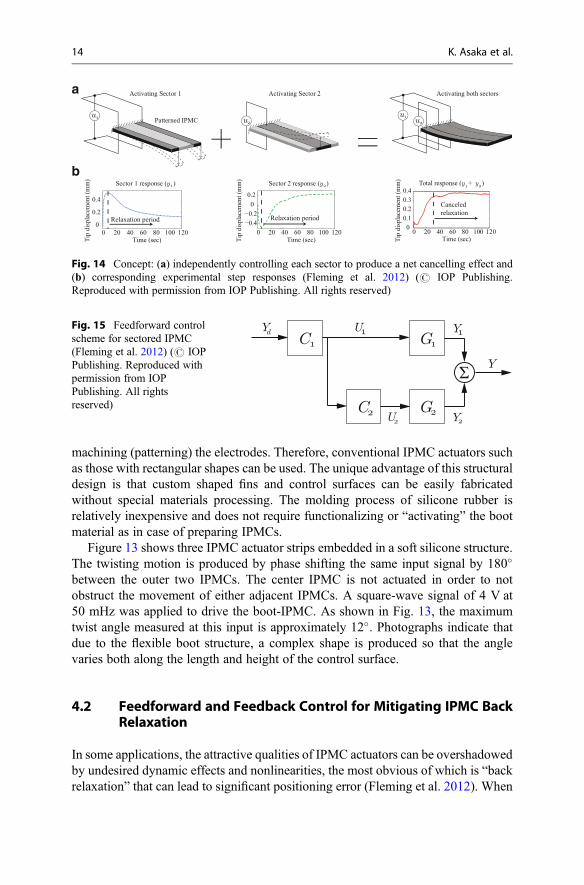
Fig. 14 Concept: (a) independently controlling each sector to produce a net cancelling effect and(b) corresponding experimental step responses (Fleming et al. 2012) (# IOP Publishing.Reproduced with permission from IOP Publishing. All rights reserved)
Fig. 15 Feedforward controlscheme for sectored IPMC(Fleming et al. 2012) (# IOPPublishing. Reproduced withpermission from IOPPublishing. All rightsreserved)
14 K. Asaka et al.

subjected to a DC voltage, a Nafion-based IPMC in the traditional cantileverconfiguration undergoes a relatively fast deflection toward the anode, followed bya slow relaxation in the opposite direction, i.e., toward the cathode (Nemat-Nasser2002). It is commonly accepted that the so-called back relaxation effect is due todiffusion forces acting on the solvent within the ionomer membrane. This effect cancause significant positioning error and compromise the use of IPMCs in static andlow-frequency applications.
Fleming et al. developed a control method to mitigate back relaxation, utilizingsectored IPMCs (Fleming et al. 2012). This method involves driving different sectorsof the IPMC in opposing directions, thereby canceling out the back relaxation. Thebasic concept is illustrated in Fig. 14, showing the relaxation experienced by eachsector when activated by opposing inputs (u1 and u2) and the net cancelling effect.
In this configuration, the outer portions of IPMC serve as one sector (Sector 1)and are driven by input u1(t), while the middle portion serves as a second sector(Sector 2) and is driven by input u2(t). Thus, the IPMC comprises two controllablesectors. To control the performance of the sectored IPMC, the feedforward architec-ture in Fig. 15 can be used. In this diagram, C1(s) and C2(s) are the controllers andG1(s) and G2(s) are their respective transfer functions associated with Sector 1 andSector 2, respectively. Yd(s) is the desired trajectory. This structure represents anopen loop version of the master–slave control system. The advantage of the openloop feedforward control method is that the sensor feedback is not required, therebysimplifying the implementation. However, feedback control can be integrated tofurther improve performance, where feedback can come from laser sensors or strain-based sensors (Leang et al. 2012). In this configuration, the input generated by C1(s)(the master controller) is fed into C2(s) (the slave controller).
The slave controller, C2(s), serves to counteract the back relaxation of Sector 1 byinducing back relaxation in the reverse direction for Sector 2. With the inputsaccordingly weighted, the back relaxation of each sector roughly cancels out.Then, C2(s) is responsible for setting U2(s) in appropriate proportion to U1(s), suchthat the IPMC sectors relax the same amount.
To account for nonlinearity, disturbances, and other undesirable effects notcaptured in the model, a feedback controller (C0(s)) can be integrated with thefeedforward controller. As shown in Fig. 16, the feedback loop is arranged suchthat the feedforward and feedback inputs (Uff(s) and Ufb(s), respectively) are addedto produce U1(s).
Fig. 16 Integrated feedforward/feedback control scheme for sectored IPMC (Fleming et al. 2012)(# IOP Publishing. Reproduced with permission from IOP Publishing. All rights reserved)
IPMCs as EAPs: How to Start Experimenting with Them 15
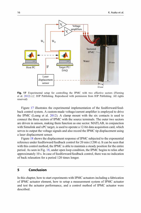
Figure 17 illustrates the experimental implementation of the feedforward/feed-back control system. A custom-made voltage/current amplifier is employed to drivethe IPMC (Leang et al. 2012). A clamp mount with the six contacts is used toconnect the three sectors of IPMC with the source terminals. The outer two sectorsare driven in unison, making them function as one sector. MATLAB, in conjunctionwith Simulink and xPC target, is used to operate a 12-bit data acquisition card, whichserves to output the voltage signals and also record the IPMC tip displacement usinga laser displacement sensor.
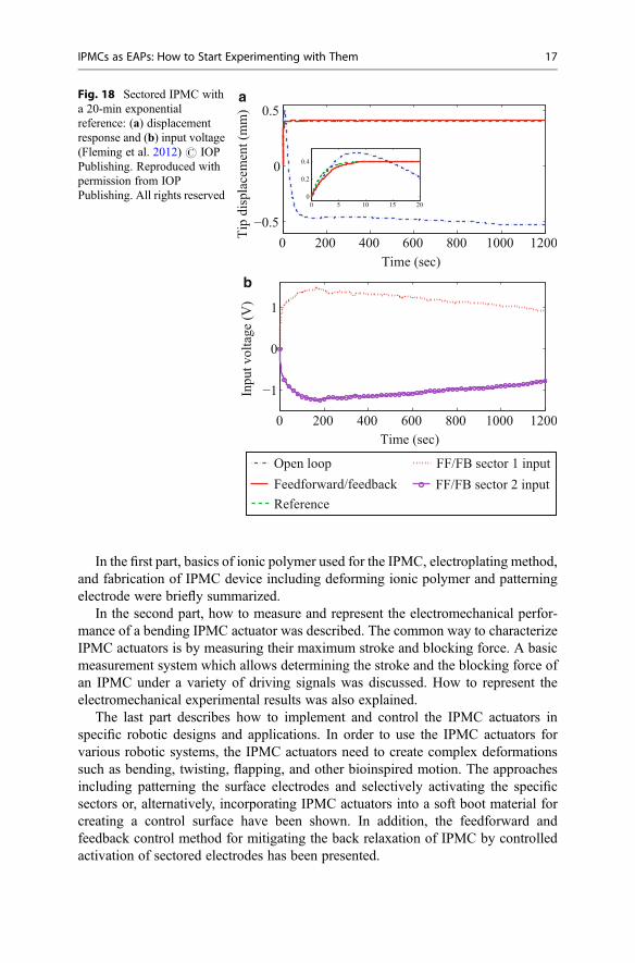
Figure 18 shows the displacement response of IPMC subjected to the exponentialreference under feedforward/feedback control for 20 min (1200 s). It can be seen thatwith this control method, the IPMC is able to maintain a steady position for the entireperiod. As seen in Fig. 18, under open loop condition, the IPMC begins to relax afterapproximately 10 s. In case of feedforward/feedback control, there was no indicationof back relaxation for a period 120 times longer.
5 Conclusion
In this chapter, how to start experiments with IPMC actuators including a fabricationof IPMC actuator element, how to setup a measurement system of IPMC actuatorand test the actuator performance, and a control method of IPMC actuator weredescribed.
Fig. 17 Experimental setup for controlling the IPMC with two effective sectors (Fleminget al. 2012) (# IOP Publishing. Reproduced with permission from IOP Publishing. All rightsreserved)
16 K. Asaka et al.
In the first part, basics of ionic polymer used for the IPMC, electroplating method,and fabrication of IPMC device including deforming ionic polymer and patterningelectrode were briefly summarized.
In the second part, how to measure and represent the electromechanical perfor-mance of a bending IPMC actuator was described. The common way to characterizeIPMC actuators is by measuring their maximum stroke and blocking force. A basicmeasurement system which allows determining the stroke and the blocking force ofan IPMC under a variety of driving signals was discussed. How to represent theelectromechanical experimental results was also explained.
The last part describes how to implement and control the IPMC actuators inspecific robotic designs and applications. In order to use the IPMC actuators forvarious robotic systems, the IPMC actuators need to create complex deformationssuch as bending, twisting, flapping, and other bioinspired motion. The approachesincluding patterning the surface electrodes and selectively activating the specificsectors or, alternatively, incorporating IPMC actuators into a soft boot material forcreating a control surface have been shown. In addition, the feedforward andfeedback control method for mitigating the back relaxation of IPMC by controlledactivation of sectored electrodes has been presented.
b
aFig. 18 Sectored IPMC witha 20-min exponentialreference: (a) displacementresponse and (b) input voltage(Fleming et al. 2012) # IOPPublishing. Reproduced withpermission from IOPPublishing. All rights reserved
IPMCs as EAPs: How to Start Experimenting with Them 17
Overall, we hope that this chapter provides useful indications on how to startexperiments with IPMC actuators. Interested readers can start the research of IPMCactuators by referring to the state-of-the-art research of IPMC, which are describedmore in detail in the preceding chapters.
References
Akle BJ, Bennett MD, Leo DJ (2006) High-strain ionomeric-ionic liquid electroactive actuators.Sens Actuators A126:173–181
Anton M, Aabloo A, Punning A, Kruusmaa M (2008) A mechanical model of a non-uniformionomeric polymer metal composite actuator. Smart Mater Struct 17(2):25001–25004
Asaka K, Oguro K (2009) Active microcatheter and biomedical soft devices based on IPMCactuators. In: Carpi F, Smela E (eds) Biomedical applications of electroactive polymer actuators.Wiley, Chichester, pp 121–136
Asaka K, Fujiwara N, Oguro K et al (2001) State of water and ionic conductivity of solid polymerelectrolyte membranes in relation to polymer actuators. J Electroanal Chem 505:24–32
Brunetto P, Fortuna L, Giannone P et al (2010) Static and dynamic characterization of thetemperature and humidity influence on IPMC actuators. IEEE Trans Instr Meas 59(4):893–908
Fleming MJ, Kim KJ, Leang KK (2012) Mitigating IPMC back relaxation through feedforward andfeedback control of patterned electrodes. Smart Mater Struct 21, 085002
Hubbard JJ, Fleming M, Palmre V et al (2014) Monolithic IPMC fins for propulsion and maneu-vering in bioinspired underwater robotics. IEEE J Ocean Eng 39(3):540–551
Jo C, Pugal D, Oh I-K et al (2013) Recent advances in ionic polymer–metal composite actuators andtheir modeling and applications. Prog Polym Sci 38:1037–1066
Kikuchi K, Tsuchitani S (2009) Nafion®-based polymer actuators with ionic liquids as solventincorporated at room temperature. J Appl Phys 106, 053519
Kim KJ, Pugal D, Leang KK (2011) A twistable ionic polymer–metal composite artificial musclefor marine applications. Mar Technol Soc J 45:83–98
Kruusam€ae K, Mukai K, Sugino T, Asaka K (2014) Mechanical behaviour of bending bucky-gelactuators and its representation. Smart Mater Struct 23(2), 025031
Leang KK, Shan Y, Song S, Kim KJ (2012) Integrated sensing for IPMC actuators using straingages for underwater applications. IEEE/ASME Trans Mechatronics 17:345–355
Moeinkhah H, Jung J-Y, Jeon J-H et al (2013) How does clamping pressure influence actuationperformance of soft ionic polymer–metal composites? Smart Mater Struct 22(2), 025014
Must I, Vunder V, Kaasik F et al (2014) Ionic liquid-based actuators working in air: the effect ofambient humidity. Sens Actuators B Chem 202:114–122
Nemat-Nasser S (2002) Micromechanics of actuation of ionic polymer–metal composites. J ApplPhys 92:2899–2915
Onishi K, Sewa S, Asaka K et al (2001a) The effects of counter ions on characterization andperformance of a solid polymer electrolyte actuator. Electrochim Acta 46:1233–1241
Onishi K, Sewa S, Asaka K et al (2001b) Morphology of electrodes and bending response of thepolymer electrolyte actuator. Electrochim Acta 46:737–743
Palmre V, Brandell D, Maeorg U et al (2009) Nanoporous carbon-based electrodes for high strainionomeric bending actuators. Smart Mater Struct 18, 095028
Palmre V, Hubbard JJ, Fleming M et al (2013) An IPMC-enabled bio-inspired bending/twisting finfor underwater applications. Smart Mater Struct 22, 014003
Punning A, Johanson U, Anton M et al (2009) A distributed model of ionomeric polymer metalcomposite. J Intell Mater Syst Struct 20(14):1711–1724
Vunder V, Punning A, Aabloo A (2012) Mechanical interpretation of back-relaxation of ionicelectroactive polymer actuators. Smart Mater Struct 21(11):115023
18 K. Asaka et al.

Yamaue T, Mukai H, Asaka K, Doi M (2005) Electrostress diffusion coupling model for polyelec-trolyte gels. Macromolecules 38:1349–1356
Yeo RS, Yeager HL (1985) Structural and transport properties of perfluorinated ion-exchangemembranes. Modern Aspect of Electrochem 16:437–505
Zhu Z, Asaka K, Chang L et al (2013a) Multiphysics of ionic polymer–metal composite actuator. JAppl Phys 114, 084902
Zhu Z, Asaka K, Chang L et al (2013b) Physical interpretation of deformation evolvement withwater content of ionic polymer-metal composite actuator. J Appl Phys 114:184902
IPMCs as EAPs: How to Start Experimenting with Them 19