ip routing: protocol-independent configuration guide, cisco ios … · ip routing:...
TRANSCRIPT
IP Routing: Protocol-Independent Configuration Guide, Cisco IOS XERelease 3S
Americas HeadquartersCisco Systems, Inc.170 West Tasman DriveSan Jose, CA 95134-1706USAhttp://www.cisco.comTel: 408 526-4000 800 553-NETS (6387)Fax: 408 527-0883

THE SPECIFICATIONS AND INFORMATION REGARDING THE PRODUCTS IN THIS MANUAL ARE SUBJECT TO CHANGE WITHOUT NOTICE. ALL STATEMENTS,INFORMATION, AND RECOMMENDATIONS IN THIS MANUAL ARE BELIEVED TO BE ACCURATE BUT ARE PRESENTED WITHOUT WARRANTY OF ANY KIND,EXPRESS OR IMPLIED. USERS MUST TAKE FULL RESPONSIBILITY FOR THEIR APPLICATION OF ANY PRODUCTS.
THE SOFTWARE LICENSE AND LIMITEDWARRANTY FOR THE ACCOMPANYING PRODUCT ARE SET FORTH IN THE INFORMATION PACKET THAT SHIPPED WITHTHE PRODUCT AND ARE INCORPORATED HEREIN BY THIS REFERENCE. IF YOU ARE UNABLE TO LOCATE THE SOFTWARE LICENSE OR LIMITED WARRANTY,CONTACT YOUR CISCO REPRESENTATIVE FOR A COPY.
The Cisco implementation of TCP header compression is an adaptation of a program developed by the University of California, Berkeley (UCB) as part of UCB's public domain versionof the UNIX operating system. All rights reserved. Copyright © 1981, Regents of the University of California.
NOTWITHSTANDINGANYOTHERWARRANTYHEREIN, ALL DOCUMENT FILES AND SOFTWARE OF THESE SUPPLIERS ARE PROVIDED “AS IS"WITH ALL FAULTS.CISCO AND THE ABOVE-NAMED SUPPLIERS DISCLAIM ALL WARRANTIES, EXPRESSED OR IMPLIED, INCLUDING, WITHOUT LIMITATION, THOSE OFMERCHANTABILITY, FITNESS FORA PARTICULAR PURPOSEANDNONINFRINGEMENTORARISING FROMACOURSEOFDEALING, USAGE, OR TRADE PRACTICE.
IN NO EVENT SHALL CISCO OR ITS SUPPLIERS BE LIABLE FOR ANY INDIRECT, SPECIAL, CONSEQUENTIAL, OR INCIDENTAL DAMAGES, INCLUDING, WITHOUTLIMITATION, LOST PROFITS OR LOSS OR DAMAGE TO DATA ARISING OUT OF THE USE OR INABILITY TO USE THIS MANUAL, EVEN IF CISCO OR ITS SUPPLIERSHAVE BEEN ADVISED OF THE POSSIBILITY OF SUCH DAMAGES.
Any Internet Protocol (IP) addresses and phone numbers used in this document are not intended to be actual addresses and phone numbers. Any examples, command display output, networktopology diagrams, and other figures included in the document are shown for illustrative purposes only. Any use of actual IP addresses or phone numbers in illustrative content is unintentionaland coincidental.
Cisco and the Cisco logo are trademarks or registered trademarks of Cisco and/or its affiliates in the U.S. and other countries. To view a list of Cisco trademarks, go to this URL: http://www.cisco.com/go/trademarks. Third-party trademarks mentioned are the property of their respective owners. The use of the word partner does not imply a partnershiprelationship between Cisco and any other company. (1110R)
© 2015 Cisco Systems, Inc. All rights reserved.

C O N T E N T S
C H A P T E R 1 Basic IP Routing 1
Finding Feature Information 1
Information About Basic IP Routing 1
Variable-Length Subnet Masks 1
Static Routes 2
Default Routes 3
Default Network 4
Gateway of Last Resort 4
Maximum Number of Paths 5
Multi-Interface Load Splitting 5
Routing Information Redistribution 5
Supported Metric Translations 6
Protocol Differences in Implementing the no redistribute Command 6
Sources of Routing Information Filtering 7
Authentication Key Management and Supported Protocols 7
How to Configure Basic IP Routing 8
Redistributing Routing Information 8
Defining Conditions for Redistributing Routes 8
Redistributing Routes from One Routing Domain to Another 11
Removing Options for Redistribution Routes 12
Configuring Routing Information Filtering 13
Controlling the Advertising of Routes in Routing Updates 13
Controlling the Processing of Routing Updates 14
Filtering Sources of Routing Information 14
Managing Authentication Keys 14
Monitoring and Maintaining the IP Network 15
Clearing Routes from the IP Routing Table 15
Displaying System and Network Statistics 16
IP Routing: Protocol-Independent Configuration Guide, Cisco IOS XE Release 3S iii
Configuration Examples for Basic IP Routing 16
Example: Variable-Length Subnet Mask 16
Example: Overriding Static Routes with Dynamic Protocols 17
Example: IP Default Gateway as a Static IP Next Hop When IP Routing Is Disabled 17
Examples: Administrative Distances 18
Example: Static Routing Redistribution 18
Examples: EIGRP Redistribution 19
Example: Mutual Redistribution Between EIGRP and RIP 19
Example: Mutual Redistribution Between EIGRP and BGP 20
Examples: OSPF Routing and Route Redistribution 21
Examples: Basic OSPF Configuration 21
Example: Internal Device ABR and ASBRs Configuration 23
Example: Complex OSPF Configuration 25
Example: Default Metric Values Redistribution 27
Examples: Redistribution With and Without Route Maps 27
Examples: Key Management 29
Additional References 30
Feature Information for Basic IP Routing 30
C H A P T E R 2 IPv6 Routing: Static Routing 33
Finding Feature Information 33
Prerequisites for IPv6 Routing: Static Routing 33
Restrictions for IPv6 Routing: Static Routing 34
Information About IPv6 Routing: Static Routing 34
Static Routes 34
Directly Attached Static Routes 34
Recursive Static Routes 35
Fully Specified Static Routes 35
Floating Static Routes 36
How to Configure IPv6 Static Routing 36
Configuring a Static IPv6 Route 36
Configuring a Recursive IPv6 Static Route to Use a Default IPv6 Static Route 37
Configuring a Floating Static IPv6 Route 38
Verifying Static IPv6 Route Configuration and Operation 39
Configuration Examples for IPv6 Static Routing 40
IP Routing: Protocol-Independent Configuration Guide, Cisco IOS XE Release 3Siv
Contents

Example Configuring Manual Summarization 40
Example: Configuring Traffic Discard 41
Example: Configuring a Fixed Default Route 41
Example: Configuring a Floating Static Route 42
Additional References 42
Feature Information for IPv6 Routing: Static Routing 43
C H A P T E R 3 IPv4 Loop-Free Alternate Fast Reroute 45
Finding Feature Information 45
Prerequisites for IPv4 Loop-Free Alternate Fast Reroute 46
Restrictions for IPv4 Loop-Free Alternate Fast Reroute 46
Information About IPv4 Loop-Free Alternate Fast Reroute 47
IS-IS and IP FRR 47
Repair Paths 47
LFA Overview 47
LFA Calculation 48
Interaction Between RIB and Routing Protocols 48
How to Configure IPv4 Loop-Free Alternate Fast Reroute 49
Configuring Fast Reroute Support 49
Configuration Examples for IPv4 Loop-Free Alternate Fast Reroute 52
Example: Configuring IPv4 Loop-Free Alternate Fast Reroute Support 52
Additional References 53
Feature Information for Configuring IPv4 Loop-Free Alternate Fast Reroute 54
C H A P T E R 4 IP Event Dampening 55
Finding Feature Information 55
Restrictions for IP Event Dampening 56
Information About IP Event Dampening 56
IP Event Dampening Overview 56
Interface State Change Events 56
Suppress Threshold 57
Half-Life Period 57
Reuse Threshold 57
Maximum Suppress Time 57
Affected Components 57
IP Routing: Protocol-Independent Configuration Guide, Cisco IOS XE Release 3S v
Contents
Route Types 57
Supported Protocols 58
Network Deployments 59
Benefits of IP Event Dampening 59
How to Configure IP Event Dampening 60
Enabling IP Event Dampening 60
Verifying IP Event Dampening 61
Configuration Examples for IP Event Dampening 62
Configuring IP Event Dampening Example 62
Verifying IP Event Dampening Example 62
Additional References 62
Feature Information for IP Event Dampening 64
Glossary 65
C H A P T E R 5 PBR Recursive Next Hop 67
Finding Feature Information 67
Restrictions for PBR Recursive Next Hop 67
Information About PBR Recursive Next-Hop 68
PBR Recursive Next Hop Overview 68
How to Configure PBR Recursive Next Hop 68
Setting the Recursive Next-Hop IP Address 68
Verifying the Recursive Next-Hop Configuration 71
Configuration Examples for PBR Recursive Next Hop 72
Example: Recursive Next-Hop IP Address 72
Additional References for PBR Recursive Next Hop 73
Feature Information for PBR Recursive Next Hop 74
C H A P T E R 6 PBR Support for Multiple Tracking Options 75
Finding Feature Information 75
Information About PBR Support for Multiple Tracking Options 75
Object Tracking 75
PBR Support for Multiple Tracking Options Feature Design 76
How to Configure PBR Support for Multiple Tracking Options 76
Cisco IOS Release 12.3(11)T 12.2(25)S and Earlier 76
Configuring PBR Support for Multiple Tracking Options 79
IP Routing: Protocol-Independent Configuration Guide, Cisco IOS XE Release 3Svi
Contents
Configuration Examples for PBR Support for Multiple Tracking Options 83
Cisco IOS Release 12.3(11)T 12.2(25)S and Earlier 83
Example: Configuring PBR Support for Multiple Tracking Options 84
Additional References 85
Command Reference 85
Feature Information for PBR Support for Multiple Tracking Options 86
C H A P T E R 7 PBR Match Track Object 87
Finding Feature Information 87
Restrictions for PBR Match Track Object 87
Information About PBR Match Track Object 88
PBR Match Track Object Overview 88
How to Configure PBR Match Track Object 89
Configuring PBR Match Track Object 89
Verifying PBR Match Track Object 90
Configuration Examples for PBR Match Track Object 90
Example: PBR Match Track Object Configuration 90
Example: Verifying PBR Match Track Object 90
Additional References for PBR Match Track Object 91
Feature Information for PBR Match Track Object 91
C H A P T E R 8 IPv6 Policy-Based Routing 93
Finding Feature Information 93
Information About IPv6 Policy-Based Routing 93
Policy-Based Routing Overview 93
How Policy-Based Routing Works 94
Packet Matching 94
Packet Forwarding Using Set Statements 95
When to Use Policy-Based Routing 96
How to Enable IPv6 Policy-Based Routing 96
Enabling IPv6 PBR on an Interface 96
Enabling Local PBR for IPv6 99
Verifying the Configuration and Operation of PBR for IPv6 100
Troubleshooting PBR for IPv6 101
Configuration Examples for IPv6 Policy-Based Routing 102
IP Routing: Protocol-Independent Configuration Guide, Cisco IOS XE Release 3S vii
Contents

Example: Enabling PBR on an Interface 102
Example: Enabling Local PBR for IPv6 102
Example: show ipv6 policy Command Output 102
Example: Verifying Route-Map Information 102
Additional References for IPv6 Policy-Based Routing 103
Feature Information for IPv6 Policy-Based Routing 103
C H A P T E R 9 Multi-VRF Selection Using Policy-Based Routing 105
Finding Feature Information 105
Prerequisites for Multi-VRF Selection Using Policy-Based Routing 106
Restrictions for Multi-VRF Selection Using Policy-Based Routing 106
Information About Multi-VRF Selection Using Policy-Based Routing 106
Policy Routing of VPN Traffic Based on Match Criteria 106
Policy-Based Routing set Commands 107
Policy-routing Packets for VRF Instances 107
Change of Normal Routing and Forwarding Behavior 108
Support of Inherit-VRF Inter-VRF and VRF-to-Global Routing 109
How to Configure Multi-VRF Selection Using Policy-Based Routing 110
Defining the Match Criteria for Multi-VRF Selection Using Policy-Based Routing 110
ConfiguringMulti-VRFSelectionUsing Policy-BasedRoutingwith a StandardAccess
List 110
ConfiguringMulti-VRF SelectionUsing Policy-BasedRoutingwith a Named Extended
Access List 111
Configuring Multi-VRF Selection in a Route Map 112
ConfiguringMulti-VRF Selection Using Policy-Based Routing and IP VRF Receive on the
Interface 115
Verifying the Configuration of Multi-VRF Selection Using Policy-Based Routing 116
Configuration Examples for Multi-VRF Selection Using Policy-Based Routing 118
Example: Defining the Match Criteria for Multi-VRF Selection Using Policy-Based
Routing 118
Example: Configuring Multi-VRF Selection in a Route Map 119
Additional References 119
Feature Information for Multi-VRF Selection Using Policy-Based Routing 120
Glossary 122
IP Routing: Protocol-Independent Configuration Guide, Cisco IOS XE Release 3Sviii
Contents

C H A P T E R 1 0 Multi-VRF Support 123
Finding Feature Information 123
Prerequisites for Multi-VRF Support 123
Restrictions for Multi-VRF Support 124
Information About Multi-VRF Support 124
How the Multi-VRF Support Feature Works 124
How Packets Are Forwarded in a Network Using the Multi-VRF Support Feature 125
Considerations When Configuring the Multi-VRF Support Feature 126
How to Configure Multi-VRF Support 126
Configuring VRFs 126
Configuring BGP as the Routing Protocol 129
Configuring PE-to-CE MPLS Forwarding and Signaling with BGP 131
Configuring a Routing Protocol Other than BGP 133
Configuring PE-to-CE MPLS Forwarding and Signaling with LDP 134
Configuration Examples for Multi-VRF Support 135
Example: Configuring Multi-VRF Support on the PE Device 136
Example: Configuring Multi-VRF Support on the CE Device 137
Additional References 138
Feature Information for Multi-VRF Support 139
C H A P T E R 1 1 Default Passive Interfaces 141
Finding Feature Information 141
Information About Default Passive Interfaces 142
Default Passive Interfaces 142
Preventing Routing Updates Through an Interface 142
How to Configure Default Passive Interfaces 143
Configuring Default Passive Interfaces 143
Configuration Examples for Default Passive Interfaces 144
Examples: Passive Interfaces Configuration for OSPF 144
Example: Default Passive Interfaces Configuration for OSPF 145
Additional References 146
Feature Information for Default Passive Interfaces 146
C H A P T E R 1 2 Policy-Based Routing 149
IP Routing: Protocol-Independent Configuration Guide, Cisco IOS XE Release 3S ix
Contents

Finding Feature Information 149
Prerequisites for Policy-Based Routing 149
Information About Policy-Based Routing 150
Policy-Based Routing 150
How to Configure Policy-Based Routing 151
Configuring Policy-Based Routing 151
Configuration Examples for Policy-Based Routing 153
Additional References 153
Feature Information for Policy-Based Routing 154
C H A P T E R 1 3 SGT Based PBR 155
Finding Feature Information 155
Restrictions for SGT Based PBR 155
Information About SGT Based PBR 156
Cisco TrustSec 156
SGT Based PBR 156
How to Configure SGT Based PBR 156
Configuring Match Security Group Tag 156
Assigning Route-Map to an Interface 158
Displaying and Verifying SGT Based PBR Configuration 158
Configuration Examples for SGT Based PBR 160
Example: SGT Based PBR 160
Additional References for SGT Based PBR 160
Feature Information for SGT Based PBR 161
C H A P T E R 1 4 SGT Based QoS 163
Finding Feature Information 163
Prerequisites for SGT Based QoS 163
Restrictions for SGT Based QoS 164
Information About SGT Based QoS 164
SGT Based QoS 164
How to Configure SGT Based QoS 164
Configuring User Group, Device, or Role Based QoS Policies 164
Configuring and Assigning Policy-Map to an Interface 165
Displaying and Verifying SGT Based QoS Configuration 167
IP Routing: Protocol-Independent Configuration Guide, Cisco IOS XE Release 3Sx
Contents

Configuration Examples for SGT Based QoS 167
Example: Configuring User Group, Device, or Role Based QoS Policies 167
Additional References for SGT Based QoS 168
Feature Information for SGT Based QoS 168
C H A P T E R 1 5 Policy-Based Routing Default Next-Hop Routes 171
Finding Feature Information 171
Information About Policy-Based Routing Default Next-Hop Routes 172
Policy-Based Routing 172
Precedence Setting in the IP Header 172
How to Configure Policy-Based Routing Default Next-Hop Routes 173
Configuring Precedence for Policy-Based Routing Default Next-Hop Routes 173
Configuration Examples for Policy-Based Routing Default Next-Hop Routes 175
Example: Policy-Based Routing 175
Additional References 176
Feature Information for Policy-Based Routing Default Next-Hop Routes 176
C H A P T E R 1 6 PBR Next-Hop Verify Availability for VRF 179
Finding Feature Information 179
Information About PBR Next-Hop Verify Availability for VRF 179
PBR Next-Hop Verify Availability for VRF Overview 179
How to Configure PBR Next-Hop Verify Availability for VRF 180
Configuring PBR Next-Hop Verify Availability for Inherited IP VRF 180
Configuring PBR Next-Hop Verify Availability for Inherited IPv6 VRF 184
Configuring PBR Next-Hop Verify Availability for Inter VRF 188
Configuration Examples for PBR Next-Hop Verify Availability for VRF 191
Example: Configuring PBR Next-Hop Verify Availability for Inherited IP VRF 191
Example: Configuring PBR Next-Hop Verify Availability for Inherited IPv6 VRF 191
Example: Configuring PBR Next-Hop Verify Availability for Inter VRF 192
Additional References for PBR Next-Hop Verify Availability for VRF 193
Feature Information for PBR Next-Hop Verify Availability for VRF 193
C H A P T E R 1 7 QoS Policy Propagation via BGP 195
Finding Feature Information 195
Prerequisites for QoS Policy Propagation via BGP 195
IP Routing: Protocol-Independent Configuration Guide, Cisco IOS XE Release 3S xi
Contents
Information About QoS Policy Propagation via BGP 196
Benefits of QoS Policy Propagation via BGP 196
How to Configure QoS Policy Propagation via BGP 196
Configuring QoS Policy Propagation via BGP Based on Community Lists 196
Configuring QoS Policy Propagation via BGP Based on the Autonomous System Path
Attribute 199
Configuring QoS Policy Propagation via BGP Based on an Access List 201
Monitoring QoS Policy Propagation via BGP 203
Configuration Examples for QoS Policy Propagation via BGP 203
Example: Configuring QoS Policy Propagation via BGP 203
Additional References 206
Feature Information for QoS Policy Propagation via BGP 207
C H A P T E R 1 8 NetFlow Policy Routing 209
Finding Feature Information 209
Prerequisites for NetFlow Policy Routing 209
Restrictions for NetFlow Policy Routing 210
Information About NetFlow Policy Routing 210
NetFlow Policy Routing 210
Next-Hop Reachability 211
Additional References 211
Feature Information for NetFlow Policy Routing 212
C H A P T E R 1 9 Recursive Static Route 213
Finding Feature Information 213
Restrictions for Recursive Static Route 213
Information About Recursive Static Route 214
How to Install Recursive Static Route 214
Installing Recursive Static Routes in a VRF 214
Installing Recursive Static Routes Using a Route Map 216
Configuration Examples for Recursive Static Route 218
Example: Installing Recursive Static Routes in a VRF 218
Example: Installing Recursive Static Routes using a Route Map 218
Additional References for Recursive Static Route 219
Feature Information for Recursive Static Routes 219
IP Routing: Protocol-Independent Configuration Guide, Cisco IOS XE Release 3Sxii
Contents
C H A P T E R 1Basic IP Routing
This module describes how to configure basic IP routing. The Internet Protocol (IP) is a network layer (Layer3) protocol that contains addressing information and some control information that enables packets to berouted. IP is documented in RFC 791 and is the primary network layer protocol in the Internet protocol suite.
• Finding Feature Information, page 1
• Information About Basic IP Routing, page 1
• How to Configure Basic IP Routing, page 8
• Configuration Examples for Basic IP Routing, page 16
• Additional References, page 30
• Feature Information for Basic IP Routing, page 30
Finding Feature InformationYour software release may not support all the features documented in this module. For the latest caveats andfeature information, see Bug Search Tool and the release notes for your platform and software release. Tofind information about the features documented in this module, and to see a list of the releases in which eachfeature is supported, see the feature information table.
Use Cisco Feature Navigator to find information about platform support and Cisco software image support.To access Cisco Feature Navigator, go to www.cisco.com/go/cfn. An account on Cisco.com is not required.
Information About Basic IP Routing
Variable-Length Subnet MasksEnhanced Interior Gateway Routing Protocol (EIGRP), Intermediate System-to-Intermediate System (IS-IS),Open Shortest Path First (OSPF), Routing Information Protocol (RIP) Version 2, and static routes supportvariable-length subnet masks (VLSMs). With VLSMs, you can use different masks for the same networknumber on different interfaces, which allows you to conserve IP addresses and more efficiently use available
IP Routing: Protocol-Independent Configuration Guide, Cisco IOS XE Release 3S 1
address space. However, using VLSMs also presents address assignment challenges for the networkadministrator and ongoing administrative challenges.
Refer to RFC 1219 for detailed information about VLSMs and how to correctly assign addresses.
Consider your decision to use VLSMs carefully. You can easily make mistakes in address assignmentsand you will generally find that the network is more difficult to monitor using VLSMs.
Note
The best way to implement VLSMs is to keep your existing addressing plan in place and gradually migratesome networks to VLSMs to recover address space.
Static RoutesStatic routes are user-defined routes that cause packets moving between a source and a destination to take aspecified path. Static routes can be important if the device cannot build a route to a particular destination.They are also useful for specifying a gateway of last resort to which all unroutable packets will be sent.
To configure a static route, use the ip route prefix mask {ip-address | interface-type interface-number[ip-address]} [distance] [name] [permanent | track number] [tag tag] global configuration command.
Static routes remains in the device configuration until you remove them (using the no ip route globalconfiguration command). However, you can override static routes with dynamic routing information throughprudent assignment of administrative distance values. An administrative distance is a rating of thetrustworthiness of a routing information source, such as an individual router or a group of routers. Numerically,an administrative distance is an integer from 0 to 255. In general, the higher the value, the lower the trustrating. An administrative distance of 255 means the routing information source cannot be trusted at all andshould be ignored.
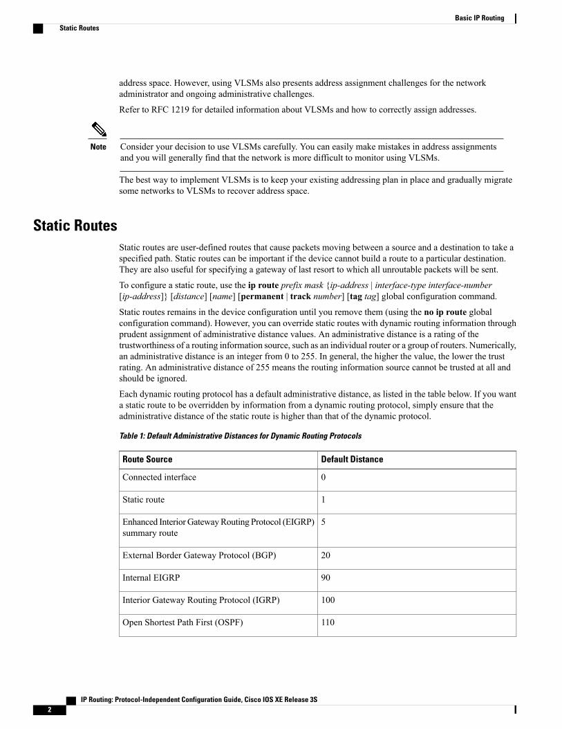
Each dynamic routing protocol has a default administrative distance, as listed in the table below. If you wanta static route to be overridden by information from a dynamic routing protocol, simply ensure that theadministrative distance of the static route is higher than that of the dynamic protocol.
Table 1: Default Administrative Distances for Dynamic Routing Protocols
Default DistanceRoute Source
0Connected interface
1Static route
5Enhanced InteriorGatewayRouting Protocol (EIGRP)summary route
20External Border Gateway Protocol (BGP)
90Internal EIGRP
100Interior Gateway Routing Protocol (IGRP)
110Open Shortest Path First (OSPF)
IP Routing: Protocol-Independent Configuration Guide, Cisco IOS XE Release 3S2
Basic IP RoutingStatic Routes

Default DistanceRoute Source
115intermediate System to Intermediate System (IS-IS)
120Routing Information Protocol (RIP)
140Exterior Gateway Routing Protocol (EGP)
160On Demand Routing (ODR)
170External EIGRP
200Internal BGP
255Unknown
Static routes that point to an interface are advertised via RIP, EIGRP, and other dynamic routing protocols,regardless of whether redistribute static router configuration commands are specified for those routingprotocols. These static routes are advertised because static routes that point to an interface are considered inthe routing table to be connected and hence lose their static nature. However, if you define a static route toan interface that is not one of the networks defined in a network command, no dynamic routing protocolswill advertise the route unless a redistribute static command is specified for these protocols.
When an interface goes down, all static routes through that interface are removed from the IP routing table.Also, when the software can no longer find a valid next hop for the address specified as the address of theforwarding device in a static route, the static route is removed from the IP routing table.
A packet with an E-class source address (240.0.0.0/4) gets dropped on Cisco ASR 1000 Series AggregationServices Routers, although RFC 1812 (Requirements for IP Version 4 Routers) defines this behavior onlyfor destination addresses and not specifically for source addresses.
Note
Default RoutesDefault routes, also known as gateways of last resort, are used to route packets that are addressed to networksnot explicitly listed in the routing table. A device might not be able to determine routes to all networks. Toprovide complete routing capability, network administrators use some devices as smart devices and give theremaining devices default routes to the smart device. (Smart devices have routing table information for theentire internetwork.) Default routes can be either passed along dynamically or configured manually intoindividual devices.
Most dynamic interior routing protocols include a mechanism for causing a smart device to generate dynamicdefault information, which is then passed along to other devices.
You can configure a default route by using the following commands:
• ip default-gateway
• ip default-network
IP Routing: Protocol-Independent Configuration Guide, Cisco IOS XE Release 3S 3
Basic IP RoutingDefault Routes
• ip route 0.0.0.0 0.0.0.0
You can use the ip default-gateway global configuration command to define a default gateway when IProuting is disabled on a device. For instance, if a device is a host, you can use this command to define a defaultgateway for the device. You can also use this command to transfer a Cisco software image to a device whenthe device is in boot mode. In boot mode, IP routing is not enabled on the device.
Unlike the ip default-gateway command, the ip default-network command can be used when IP routing isenabled on a device. When you specify a network by using the ip default-network command, the deviceconsiders routes to that network for installation as the gateway of last resort on the device.
Gateways of last resort configured by using the ip default-network command are propagated differentlydepending on which routing protocol is propagating the default route. For Interior Gateway Routing Protocol(IGRP) and Enhanced Interior Gateway Routing Protocol (EIGRP) to propagate the default route, the networkspecified by the ip default-network command must be known to IGRP or EIGRP. The network must be anIGRP- or EIGRP-derived network in the routing table, or the static route used to generate the route to thenetwork must be redistributed into IGRP or EIGRP or advertised into these protocols by using the networkcommand. The Routing Information Protocol (RIP) advertises a route to network 0.0.0.0 if a gateway of lastresort is configured by using the ip default-network command. The network specified in the ipdefault-network command need not be explicitly advertised under RIP.
Creating a static route to network 0.0.0.0 0.0.0.0 by using the ip route 0.0.0.0 0.0.0.0 command is anotherway to set the gateway of last resort on a device. As with the ip default-network command, using the staticroute to 0.0.0.0 is not dependent on any routing protocols. However, IP routing must be enabled on the device.IGRP does not recognize a route to network 0.0.0.0. Therefore, it cannot propagate default routes created byusing the ip route 0.0.0.0 0.0.0.0 command. Use the ip default-network command to have IGRP propagatea default route.
EIGRP propagates a route to network 0.0.0.0, but the static route must be redistributed into the routing protocol.
Depending on your release of the Cisco software, the default route created by using the ip route 0.0.0.0 0.0.0.0command is automatically advertised by RIP devices. In some releases, RIP does not advertise the defaultroute if the route is not learned via RIP. You might have to redistribute the route into RIP by using theredistribute command.
Default routes created using the ip route 0.0.0.0 0.0.0.0 command are not propagated by Open Shortest PathFirst (OSPF) and Intermediate System to Intermediate System (IS-IS). Additionally, these default routescannot be redistributed into OSPF or IS-IS by using the redistribute command. Use the default-informationoriginate command to generate a default route into an OSPF or IS-IS routing domain.
Default NetworkDefault networks are used to route packets to destinations not established in the routing table. You can usethe ip default-network network-number global configuration command to configure a default network whenIP routing is enabled on the device. When you configure a default network, the device considers routes to thatnetwork for installation as the gateway of last resort on the device.
Gateway of Last ResortWhen default information is being passed along through a dynamic routing protocol, no further configurationis required. The system periodically scans its routing table to choose the optimal default network as its defaultroute. In the case of the Routing Information Protocol (RIP), there is only one choice, network 0.0.0.0. In thecase of Enhanced Interior Gateway Routing Protocol (EIGRP), there might be several networks that can becandidates for the system default. Cisco software uses both administrative distance and metric information to
IP Routing: Protocol-Independent Configuration Guide, Cisco IOS XE Release 3S4
Basic IP RoutingDefault Routes

determine the default route (gateway of last resort). The selected default route appears in the gateway of lastresort display of the show ip route privileged EXEC command.
If dynamic default information is not being passed to the software, candidates for the default route are specifiedwith the ip default-network global configuration command. In this usage, the ip default-network commandtakes an unconnected network as an argument. If this network appears in the routing table from any source(dynamic or static), it is flagged as a candidate default route and is a possible choice as the default route.
If the device has no interface on the default network, but does have a route to it, it considers this network asa candidate default path. The route candidates are examined and the best one is chosen, based on administrativedistance and metric. The gateway to the best default path becomes the gateway of last resort.
Maximum Number of PathsBy default, most IP routing protocols install a maximum of four parallel routes in a routing table. Static routesalways install six routes. The exception is Border Gateway Protocol (BGP), which by default allows only onepath (the best path) to a destination. However, BGP can be configured to use equal and unequal cost multipathload sharing.
The number of parallel routes that you can configure to be installed in the routing table is dependent on theinstalled version of Cisco software. To change the maximum number of parallel paths allowed, use themaximum-paths number-paths command in router configuration mode.
Multi-Interface Load SplittingMulti-interface load splitting allows you to efficiently control traffic that travels across multiple interfaces tothe same destination. The traffic-share min router configuration command specifies that if multiple pathsare available to the same destination, only paths with the minimummetric will be installed in the routing table.The number of paths allowed is never more than six. For dynamic routing protocols, the number of paths iscontrolled by themaximum-paths router configuration command. The static route source can install sixpaths. If more paths are available, the extra paths are discarded. If some installed paths are removed from therouting table, pending routes are added automatically.
Routing Information RedistributionIn addition to running multiple routing protocols simultaneously, Cisco software can be configured toredistribute information from one routing protocol to another. For example, you can configure a device toreadvertise Enhanced Interior GatewayRouting Protocol (EIGRP)-derived routes using the Routing InformationProtocol (RIP), or to readvertise static routes using the EIGRP protocol. Redistribution from one routingprotocol to another can be configured in all of the IP-based routing protocols.
You also can conditionally control the redistribution of routes between routing domains by configuring routemaps between the two domains. A route map is a route/packet filter that is configured with permit and denystatements, match and set clauses, and sequence numbers.
Although redistribution is a protocol-independent feature, some of thematch and set commands are specificto a particular protocol.
One or morematch commands and one or more set commands are configured in route map configurationmode. If there are no match commands, then everything matches. If there are no set commands, then no setaction is performed.
IP Routing: Protocol-Independent Configuration Guide, Cisco IOS XE Release 3S 5
Basic IP RoutingMaximum Number of Paths

To define a route map for redistribution, use the route-map map-tag [permit | deny] [sequence-number]global configuration command.
The metrics of one routing protocol do not necessarily translate into the metrics of another. For example, theRIP metric is a hop count and the EIGRP metric is a combination of five metric values. In such situations, adynamicmetric is assigned to the redistributed route. Redistribution in these cases should be applied consistentlyand carefully with inbound filtering to avoid routing loops.
Removing options that you have configured for the redistribute command requires careful use of the noredistribute command to ensure that you obtain the result that you are expecting.
Supported Metric TranslationsThis section describes supported automatic metric translations between the routing protocols. The followingdescriptions assume that you have not defined a default redistribution metric that replaces metric conversions:
• The Routing Information Protocol (RIP) can automatically redistribute static routes. It assigns staticroutes a metric of 1 (directly connected).
• The Border Gateway Protocol (BGP) does not normally send metrics in its routing updates.
• The Enhanced Interior Gateway Routing Protocol (EIGRP) can automatically redistribute static routesfrom other EIGRP-routed autonomous systems as long as the static route and any associated interfacesare covered by an EIGRP network statement. EIGRP assigns static routes a metric that identifies themas directly connected. EIGRP does not change the metrics of routes derived from EIGRP updates fromother autonomous systems.
Note that any protocol can redistribute routes from other routing protocols as long as a default metric isconfigured.
Note
Protocol Differences in Implementing the no redistribute Command
Removing options that you have configured for the redistribute command requires careful use of the noredistribute command to ensure that you obtain the result that you are expecting. In most cases, changingor disabling any keyword will not affect the state of other keywords.
Caution
Different protocols implement the no redistribute command differently as follows:
• In Border Gateway Protocol (BGP), Open Shortest Path First (OSPF), and Routing Information Protocol(RIP) configurations, the no redistribute command removes only the specified keywords from theredistribute commands in the running configuration. They use the subtractive keyword method whenredistributing from other protocols. For example, in the case of BGP, if you configure no redistributestatic route-map interior, only the route map is removed from the redistribution, leaving redistributestatic in place with no filter.
• The no redistribute isis command removes the Intermediate System to Intermediate System (IS-IS)redistribution from the running configuration. IS-IS removes the entire command, regardless of whetherIS-IS is the redistributed or redistributing protocol.
IP Routing: Protocol-Independent Configuration Guide, Cisco IOS XE Release 3S6
Basic IP RoutingRouting Information Redistribution

• The Enhanced Interior Gateway Routing Protocol (EIGRP) used the subtractive keyword method priorto EIGRP component version rel5. Starting with EIGRP component version rel5, the no redistributecommand removes the entire redistribute command when redistributing from any other protocol.
Sources of Routing Information FilteringFiltering sources of routing information prioritizes routing information from different sources because somepieces of routing information might be more accurate than others. An administrative distance is a rating ofthe trustworthiness of a routing information source, such as an individual device or a group of devices. In alarge network, some routing protocols and some devices can be more reliable than others as sources of routinginformation. Also, when multiple routing processes are running in the same device for IP, the same routecould be advertised by more than one routing process. By specifying administrative distance values, youenable the device to intelligently discriminate between sources of routing information. The device alwayspicks the route whose routing protocol has the lowest administrative distance.
There are no general guidelines for assigning administrative distances because each network has its ownrequirements. You must determine a reasonable matrix of administrative distances for the network as a whole.
For example, consider a device using the Enhanced Interior Gateway Routing Protocol (EIGRP) and theRouting Information Protocol (RIP). Suppose you trust the EIGRP-derived routing information more than theRIP-derived routing information. In this example, because the default EIGRP administrative distance is lowerthan the default RIP administrative distance, the device uses the EIGRP-derived information and ignores theRIP-derived information. However, if you lose the source of the EIGRP-derived information (because of apower shutdown at the source network, for example), the device uses the RIP-derived information until theEIGRP-derived information reappears.
You can also use administrative distance to rate the routing information from devices that are running thesame routing protocol. This application is generally discouraged if you are unfamiliar with this particularuse of administrative distance because it can result in inconsistent routing information, including forwardingloops.
Note
The weight of a route can no longer be set with the distance command. To set the weight for a route, usea route map.
Note
Authentication Key Management and Supported ProtocolsKeymanagement is a method of controlling the authentication keys used by routing protocols. Not all protocolssupport key management. Authentication keys are available for Director Response Protocol (DRP) Agent,Enhanced Interior Gateway Routing Protocol (EIGRP), and Routing Information Protocol (RIP) Version 2.
You can manage authentication keys by defining key chains, identifying the keys that belong to the key chain,and specifying how long each key is valid. Each key has its own key identifier (specified using the key chainconfiguration command), which is stored locally. The combination of the key identifier and the interfaceassociated with the message uniquely identifies the authentication algorithm and the message digest algorithm5 (MD5) authentication key in use.
IP Routing: Protocol-Independent Configuration Guide, Cisco IOS XE Release 3S 7
Basic IP RoutingSources of Routing Information Filtering

You can configure multiple keys with lifetimes. Only one authentication packet is sent, regardless of howmany valid keys exist. The software examines the key numbers in ascending order and uses the first valid keyit encounters. The lifetimes allow for overlap during key changes.
How to Configure Basic IP Routing
Redistributing Routing InformationYou can redistribute routes from one routing domain into another, with or without controlling the redistributionwith a route map. To control which routes are redistributed, configure a route map and reference the routemap from the redistribute command.
The tasks in this section describe how to define the conditions for redistributing routes (a route map), how toredistribute routes, and how to remove options for redistributing routes, depending on the protocol being used.
Defining Conditions for Redistributing RoutesRoute maps can be used to control route redistribution (or to implement policy-based routing). To defineconditions for redistributing routes from one routing protocol into another, configure the route-map command.Then use at least onematch command in route map configuration mode, as needed. At least onematchcommand is used in this task because the purpose of the task is to illustrate how to define one or more conditionson which to base redistribution.
A route map is not required to havematch commands; it can have only set commands. If there are nomatch commands, everything matches the route map.
Note
IP Routing: Protocol-Independent Configuration Guide, Cisco IOS XE Release 3S8
Basic IP RoutingHow to Configure Basic IP Routing

There are many morematch commands not shown in this table. For additionalmatch commands, see theCisco IOS Master Command List.
Note
PurposeCommand or Action
Matches a BGP autonomous system path accesslist.match as-path path-list-number
Matches a BGP community.match community {standard-list-number |expanded-list-number | community-list-name matchcommunity[exact]}
Matches routes that have a destination networkaddress that is permitted to policy route packets oris permitted by a standard access list, an extendedaccess list, or a prefix list.
match ip address {access-list-number[access-list-number... | access-list-name...] |access-list-name [access-list-number...|access-list-name] | prefix-list prefix-list-name[prefix-list-name...]}
Matches routes with the specified metric.match metric metric-value
Matches a next-hop device address passed by oneof the specified access lists.match ip next-hop {access-list-number |
access-list-name} [access-list-number |access-list-name]
Matches the specified tag value.match tag tag-value [tag-value]
Matches routes that use the specified interface asthe next hop.match interface type number [type number]
Matches the address specified by the advertisedaccess lists.match ip route-source {access-list-number |
access-list-name} [access-list-number |access-list-name]
Matches the specified route type.match route-type {local | internal | external[type-1 | type-2] | level-1 | level-2}
To optionally specify the routing actions for the system to perform if the match criteria are met (for routesthat are being redistributed by the route map), use one or more set commands in route map configurationmode, as needed.
A route map is not required to have set commands; it can have onlymatch commands.Note
IP Routing: Protocol-Independent Configuration Guide, Cisco IOS XE Release 3S 9
Basic IP RoutingRedistributing Routing Information

There are more set commands not shown in this table. For additional set commands, see the Cisco IOSMaster Command List.
Note
PurposeCommand or Action
Sets the community attribute (for BGP).set community {community-number [additive][well-known]| none}
Sets route dampening parameters (for BGP).set dampening halflife reuse suppressmax-suppress-time
Assigns a local preference value to a path (forBGP).set local-preference number-value
Sets the route origin code.set origin {igp | egp as-number | incomplete}
Modifies the autonomous system path (for BGP).set as-path{tag | prepend as-path-string }
Specifies the address of the next hop.set next-hop next-hop
Enables automatic computation of the tag table.set automatic-tag
Specifies the areas to import routes.set level {level-1 | level-2 | level-1-2 | stub-area| backbone}
Sets the metric value for redistributed routes (forany protocol, except EIGRP).set metric metric-value
Sets the metric value for redistributed routes (forEIGRP only).set metric bandwidth delay reliability load mtu
Sets the metric type for redistributed routes.set metric-type {internal | external | type-1 |type-2}
Sets theMulti Exit Discriminator (MED) value onprefixes advertised to the external BGP neighborto match the Interior Gateway Protocol (IGP)metric of the next hop.
set metric-type internal
Sets a tag value to be applied to redistributedroutes.set tag tag-value
IP Routing: Protocol-Independent Configuration Guide, Cisco IOS XE Release 3S10
Basic IP RoutingRedistributing Routing Information

Redistributing Routes from One Routing Domain to AnotherPerform this task to redistribute routes from one routing domain into another and to control route redistribution.This task shows how to redistribute OSPF routes into a BGP domain.
SUMMARY STEPS
1. enable2. configure terminal3. router bgp autonomous-system4. redistribute protocol process-id5. default-metric number6. end
DETAILED STEPS
PurposeCommand or Action
Enables privileged EXEC mode.enableStep 1
Example:Device> enable
• Enter your password if prompted.
Enters global configuration mode.configure terminal
Example:
Device# configure terminal
Step 2
Enables a BGP routing process and enters router configurationmode.
router bgp autonomous-system
Example:
Device(config)# router bgp 109
Step 3
Redistributes routes from the specified routing domain intoanother routing domain.
redistribute protocol process-id
Example:Device(config-router)# redistribute ospf 21
Step 4
Sets the default metric value for redistributed routes.default-metric numberStep 5
Example:Device(config-router)# default-metric 10
The metric value specified in the redistributecommand supersedes the metric value specified usingthe default-metric command.
Note
Exits router configurationmode and returns to privileged EXECmode.
end
Example:Device(config-router)# end
Step 6
IP Routing: Protocol-Independent Configuration Guide, Cisco IOS XE Release 3S 11
Basic IP RoutingRedistributing Routing Information
Removing Options for Redistribution Routes
Removing options that you have configured for the redistribute command requires careful use of the noredistribute command to ensure that you obtain the result that you are expecting.
Caution
Different protocols implement the no redistribute command differently as follows:
• In BGP, OSPF, and RIP configurations, the no redistribute command removes only the specifiedkeywords from the redistribute commands in the running configuration. They use the subtractivekeyword method when redistributing from other protocols. For example, in the case of BGP, if youconfigure no redistribute static route-map interior, only the route map is removed from theredistribution, leaving redistribute static in place with no filter.
• The no redistribute isis command removes the IS-IS redistribution from the running configuration.IS-IS removes the entire command, regardless of whether IS-IS is the redistributed or redistributingprotocol.
• EIGRP used the subtractive keyword method prior to EIGRP component version rel5. Starting withEIGRP component version rel5, the no redistribute command removes the entire redistribute commandwhen redistributing from any other protocol.
• For the no redistribute connected command, the behavior is subtractive if the redistribute commandis configured under the router bgp or the router ospf command. The behavior is complete removal ofthe command if it is configured under the router isis or the router eigrp command.
IP Routing: Protocol-Independent Configuration Guide, Cisco IOS XE Release 3S12
Basic IP RoutingRedistributing Routing Information

The following OSPF commands illustrate how various options are removed from the redistribution in routerconfiguration mode.
PurposeCommand or Action
Removes the configuredmetric value of 1000 and theconfigured subnets and retainsthe redistribute connectedcommand in theconfiguration.
no redistribute connected metric 1000 subnets
Removes the configuredmetric value of 1000 andretains the redistributeconnected subnets commandin the configuration.
no redistribute connected metric 1000
Removes the configuredsubnets and retains theredistribute connectedmetric metric-valuecommand in theconfiguration.
no redistribute connected subnets
Removes the redistributeconnected command and anyof the options that wereconfigured for the command.
no redistribute connected
Configuring Routing Information Filtering
When routes are redistributed between Open Shortest Path First (OSPF) processes, no OSPF metrics arepreserved.
Note
Controlling the Advertising of Routes in Routing UpdatesTo prevent other devices from learning one or more routes, you can suppress routes from being advertised inrouting updates. To suppress routes from being advertised in routing updates, use the distribute-list{access-list-number | access-list-name} out [interface-name | routing-process | as-number] command in routerconfiguration mode.
You cannot specify an interface name in Open Shortest Path First (OSPF). When used for OSPF, this featureapplies only to external routes.
IP Routing: Protocol-Independent Configuration Guide, Cisco IOS XE Release 3S 13
Basic IP RoutingConfiguring Routing Information Filtering
Controlling the Processing of Routing UpdatesYou might want to avoid processing certain routes that are listed in incoming updates (this does not apply toOpen Shortest Path First [OSPF] or Intermediate System to Intermediate System [IS-IS]). To suppress routesin incoming updates, use the distribute-list {access-list-number | access-list-name} in [interface-typeinterface-number] command in router configuration mode.
Filtering Sources of Routing InformationTo filter sources of routing information, use the distance ip-address wildcard- mask [ip-standard-acl |ip-extended-acl | access-list-name] command in router configuration mode.
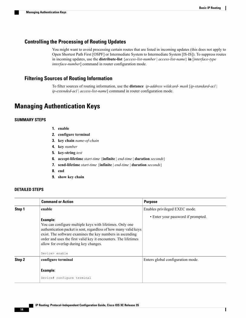
Managing Authentication Keys
SUMMARY STEPS
1. enable2. configure terminal3. key chain name-of-chain4. key number5. key-string text6. accept-lifetime start-time {infinite | end-time | duration seconds}7. send-lifetime start-time {infinite | end-time | duration seconds}8. end9. show key chain
DETAILED STEPS
PurposeCommand or Action
Enables privileged EXEC mode.enableStep 1
Example:• Enter your password if prompted.
You can configure multiple keys with lifetimes. Only oneauthentication packet is sent, regardless of howmany valid keysexist. The software examines the key numbers in ascendingorder and uses the first valid key it encounters. The lifetimesallow for overlap during key changes.
Device> enable
Enters global configuration mode.configure terminal
Example:
Device# configure terminal
Step 2
IP Routing: Protocol-Independent Configuration Guide, Cisco IOS XE Release 3S14
Basic IP RoutingManaging Authentication Keys
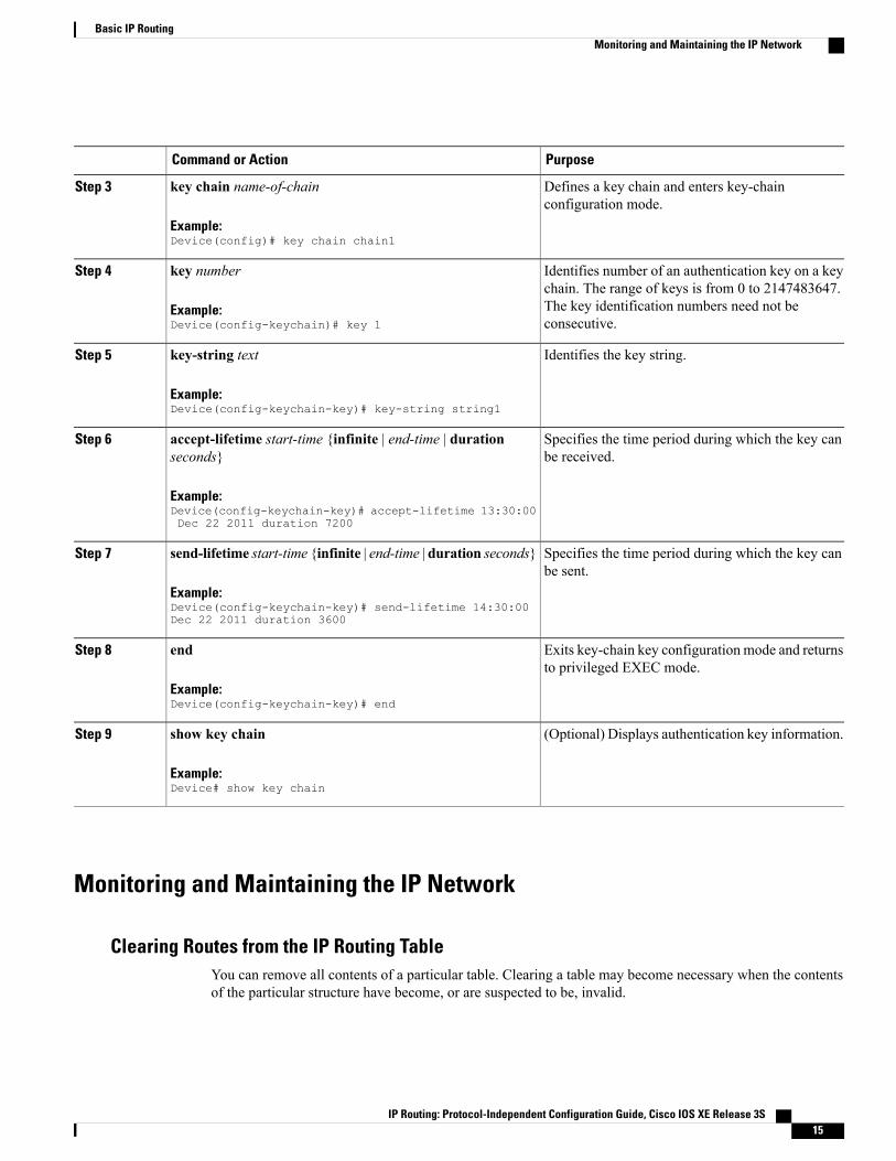
PurposeCommand or Action
Defines a key chain and enters key-chainconfiguration mode.
key chain name-of-chain
Example:Device(config)# key chain chain1
Step 3
Identifies number of an authentication key on a keychain. The range of keys is from 0 to 2147483647.
key number
Example:Device(config-keychain)# key 1
Step 4
The key identification numbers need not beconsecutive.
Identifies the key string.key-string text
Example:Device(config-keychain-key)# key-string string1
Step 5
Specifies the time period during which the key canbe received.
accept-lifetime start-time {infinite | end-time | durationseconds}
Example:Device(config-keychain-key)# accept-lifetime 13:30:00Dec 22 2011 duration 7200
Step 6
Specifies the time period during which the key canbe sent.
send-lifetime start-time {infinite | end-time | duration seconds}
Example:Device(config-keychain-key)# send-lifetime 14:30:00Dec 22 2011 duration 3600
Step 7
Exits key-chain key configuration mode and returnsto privileged EXEC mode.
end
Example:Device(config-keychain-key)# end
Step 8
(Optional) Displays authentication key information.show key chain
Example:Device# show key chain
Step 9
Monitoring and Maintaining the IP Network
Clearing Routes from the IP Routing TableYou can remove all contents of a particular table. Clearing a table may become necessary when the contentsof the particular structure have become, or are suspected to be, invalid.
IP Routing: Protocol-Independent Configuration Guide, Cisco IOS XE Release 3S 15
Basic IP RoutingMonitoring and Maintaining the IP Network
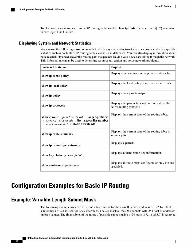
To clear one or more routes from the IP routing table, use the clear ip route {network [mask] | *} commandin privileged EXEC mode.
Displaying System and Network StatisticsYou can use the following show commands to display system and network statistics. You can display specificstatistics such as contents of IP routing tables, caches, and databases. You can also display information aboutnode reachability and discover the routing path that packets leaving your device are taking through the network.This information can an be used to determine resource utilization and solve network problems.
PurposeCommand or Action
Displays cache entries in the policy route cache.show ip cache policy
Displays the local policy route map if one exists.show ip local policy
Displays policy route maps.show ip policy
Displays the parameters and current state of theactive routing protocols.show ip protocols
Displays the current state of the routing table.show ip route [ip-address [mask] [longer-prefixes]| protocol [process-id] | list {access-list-number| access-list-name} | static download]
Displays the current state of the routing table insummary form.show ip route summary
Displays supernets.show ip route supernets-only
Displays authentication key information.show key chain [name-of-chain]
Displays all route maps configured or only the onespecified.show route-map [map-name]
Configuration Examples for Basic IP Routing
Example: Variable-Length Subnet MaskThe following example uses two different subnet masks for the class B network address of 172.16.0.0. Asubnet mask of /24 is used for LAN interfaces. The /24 mask allows 265 subnets with 254 host IP addresseson each subnet. The final subnet of the range of possible subnets using a /24 mask (172.16.255.0) is reserved
IP Routing: Protocol-Independent Configuration Guide, Cisco IOS XE Release 3S16
Basic IP RoutingConfiguration Examples for Basic IP Routing
for use on point-to-point interfaces and assigned a longer mask of /30. The use of a /30 mask on 172.16.255.0creates 64 subnets (172.16.255.0 to 172.16.255.252) with 2 host addresses on each subnet.
Caution: To ensure unambiguous routing, you must not assign 172.16.255.0/24 to a LAN interface in yournetwork.
Device(config)# interface GigabitEthernet 0/0/0Device(config-if)# ip address 172.16.1.1 255.255.255.0Device(config-if)# ! 8 bits of host address space reserved for GigabitEthernet interfacesDevice(config-if)# exitDevice(config)# interface Serial 0/0/0Device(config-if)# ip address 172.16.255.5 255.255.255.252Device(config-if)# ! 2 bits of address space reserved for point-to-point serial interfacesDevice(config-if)# exitDevice(config)# router ripDevice(config-router)# network 172.16.0.0Device(config-router)# ! Specifies the network directly connected to the device
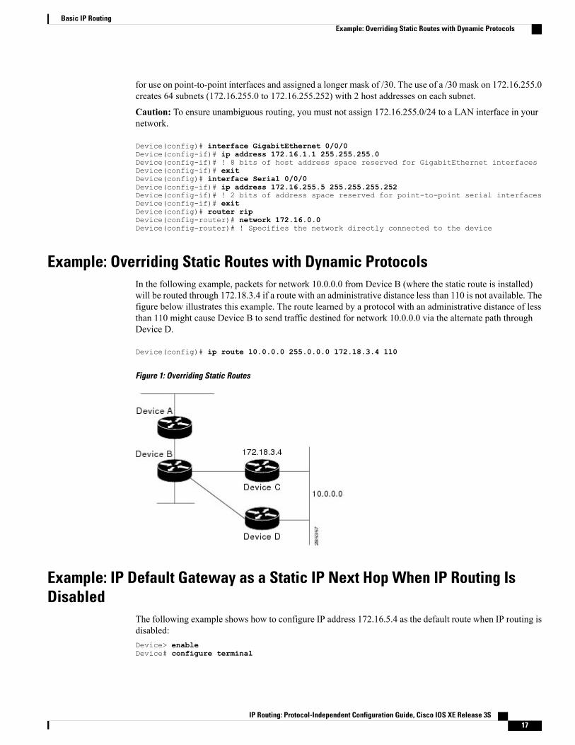
Example: Overriding Static Routes with Dynamic ProtocolsIn the following example, packets for network 10.0.0.0 from Device B (where the static route is installed)will be routed through 172.18.3.4 if a route with an administrative distance less than 110 is not available. Thefigure below illustrates this example. The route learned by a protocol with an administrative distance of lessthan 110 might cause Device B to send traffic destined for network 10.0.0.0 via the alternate path throughDevice D.
Device(config)# ip route 10.0.0.0 255.0.0.0 172.18.3.4 110
Figure 1: Overriding Static Routes
Example: IP Default Gateway as a Static IP Next Hop When IP Routing IsDisabled
The following example shows how to configure IP address 172.16.5.4 as the default route when IP routing isdisabled:Device> enableDevice# configure terminal
IP Routing: Protocol-Independent Configuration Guide, Cisco IOS XE Release 3S 17
Basic IP RoutingExample: Overriding Static Routes with Dynamic Protocols
Device(conf)# no ip routingDevice(conf)# ip default-gateway 172.16.15.4
Examples: Administrative DistancesIn the following example, the router eigrp global configuration command configures Enhanced InteriorGateway Routing Protocol (EIGRP) routing in autonomous system 1. The network command configurationspecifies EIGRP routing on networks 192.168.7.0 and 172.16.0.0. The first distance router configurationcommand sets the default administrative distance to 255, which instructs the device to ignore all routingupdates from devices for which an explicit distance has not been set. The second distance command sets theadministrative distance to 80 for internal EIGRP routes and to 100 for external EIGRP routes. The thirddistance command sets the administrative distance to 120 for the device with the address 172.16.1.3.
Device(config)# router eigrp 1Device(config-router)# network 192.168.7.0Device(config-router)# network 172.16.0.0Device(config-router)# distance 255Device(config-router)# distance eigrp 80 100Device(config-router)# distance 120 172.16.1.3 0.0.0.0
The distance eigrp command must be used to set the administrative distance for EIGRP-derived routes.Note
The following example assigns the device with the address 192.168.7.18 an administrative distance of 100and all other devices on subnet 192.168.7.0 an administrative distance of 200:
Device(config-router)# distance 100 192.168.7.18 0.0.0.0Device(config-router)# distance 200 192.168.7.0 0.0.0.255However, if you reverse the order of these two commands, all devices on subnet 192.168.7.0 are assigned anadministrative distance of 200, including the device at address 192.168.7.18:
Device(config-router)# distance 200 192.168.7.0 0.0.0.255Device(config-router)# distance 100 192.168.7.18 0.0.0.0
Assigning administrative distances can be used to solve unique problems. However, administrative distancesshould be applied carefully and consistently to avoid the creation of routing loops or other network failures.
Note
In the following example, the distance value for IP routes learned is 90. Preference is given to these IP routesrather than routes with the default administrative distance value of 110.
Device(config)# router isisDevice(config-router)# distance 90 ip
Example: Static Routing RedistributionIn the example that follows, three static routes are specified, two of which are to be advertised. The staticroutes are created by specifying the redistribute static router configuration command and then specifyingan access list that allows only those two networks to be passed to the Enhanced Interior Gateway RoutingProtocol (EIGRP) process. Any redistributed static routes should be sourced by a single device to minimizethe likelihood of creating a routing loop.
Device(config)# ip route 192.168.2.0 255.255.255.0 192.168.7.65
IP Routing: Protocol-Independent Configuration Guide, Cisco IOS XE Release 3S18
Basic IP RoutingExamples: Administrative Distances
Device(config)# ip route 192.168.5.0 255.255.255.0 192.168.7.65Device(config)# ip route 10.10.10.0 255.255.255.0 10.20.1.2Device(config)# !Device(config)# access-list 3 permit 192.168.2.0 0.0.255.255Device(config)# access-list 3 permit 192.168.5.0 0.0.255.255Device(config)# access-list 3 permit 10.10.10.0 0.0.0.255Device(config)# !Device(config)# router eigrp 1Device(config-router)# network 192.168.0.0Device(config-router)# network 10.10.10.0Device(config-router)# redistribute static metric 10000 100 255 1 1500Device(config-router)# distribute-list 3 out static
Examples: EIGRP RedistributionEach Enhanced Interior Gateway Routing Protocol (EIGRP) routing process provides routing information toonly one autonomous system. The Cisco software must run a separate EIGRP process and maintain a separaterouting database for each autonomous system that it services. However, you can transfer routing informationbetween these routing databases.
In the following configuration, network 10.0.0.0 is configured under EIGRP autonomous system 1 and network192.168.7.0 is configured under EIGRP autonomous system 101:
Device(config)# router eigrp 1Device(config-router)# network 10.0.0.0Device(config-router)# exitDevice(config)# router eigrp 101Device(config-router)# network 192.168.7.0In the following example, routes from the 192.168.7.0 network are redistributed into autonomous system 1(without passing any other routing information from autonomous system 101):
Device(config)# access-list 3 permit 192.168.7.0Device(config)# !Device(config)# route-map 101-to-1 permit 10Device(config-route-map)# match ip address 3Device(config-route-map)# set metric 10000 100 1 255 1500Device(config-route-map)# exitDevice(config)# router eigrp 1Device(config-router)# redistribute eigrp 101 route-map 101-to-1Device(config-router)#!The following example is an alternative way to redistribute routes from the 192.168.7.0 network intoautonomous system 1. Unlike the previous configuration, this method does not allow you to set the metric forredistributed routes.
Device(config)# access-list 3 permit 192.168.7.0Device(config)# !Device(config)# router eigrp 1Device(config-router)# redistribute eigrp 101Device(config-router)# distribute-list 3 out eigrp 101Device(config-router)# !
Example: Mutual Redistribution Between EIGRP and RIPConsider a WAN at a university that uses the Routing Information Protocol (RIP) as an interior routingprotocol. Assume that the university wants to connect its WAN to regional network 172.16.0.0, which usesthe Enhanced Interior Gateway Routing Protocol (EIGRP) as the routing protocol. The goal in this case is toadvertise the networks in the university network to devices in the regional network.
IP Routing: Protocol-Independent Configuration Guide, Cisco IOS XE Release 3S 19
Basic IP RoutingExamples: EIGRP Redistribution

Mutual redistribution is configured between EIGRP and RIP in the following example:
Device(config)# access-list 10 permit 172.16.0.0Device(config)# !Device(config)# router eigrp 1Device(config-router)# network 172.16.0.0Device(config-router)# redistribute rip metric 10000 100 255 1 1500Device(config-router)# default-metric 10Device(config-router)# distribute-list 10 out ripDevice(config-router)# exitDevice(config)# router ripDevice(config-router)# redistribute eigrp 1Device(config-router)# !In this example, an EIGRP routing process is started. The network router configuration command specifiesthat network 172.16.0.0 (the regional network) is to send and receive EIGRP routing information. Theredistribute router configuration command specifies that RIP-derived routing information be advertised inrouting updates. The default-metric router configuration command assigns an EIGRPmetric to all RIP-derivedroutes. The distribute-list router configuration command instructs the Cisco software to use access list 10(not defined in this example) to limit the entries in each outgoing update. The access list prevents unauthorizedadvertising of university routes to the regional network.
Example: Mutual Redistribution Between EIGRP and BGPIn the following example, mutual redistribution is configured between the Enhanced Interior Gateway RoutingProtocol (EIGRP) and the Border Gateway Protocol (BGP).
Routes fromEIGRP routing process 101 are injected into BGP autonomous system 50000. A filter is configuredto ensure that the correct routes are advertised, in this case, three networks. Routes from BGP autonomoussystem 50000 are injected into EIGRP routing process 101. The same filter is used.
Device(config)# ! All networks that should be advertised from R1 are controlled with ACLs:
Device(config)# access-list 1 permit 172.18.0.0 0.0.255.255Device(config)# access-list 1 permit 172.16.0.0 0.0.255.255Device(config)# access-list 1 permit 172.25.0.0 0.0.255.255Device(config)# ! Configuration for router R1:Device(config)# router bgp 50000Device(config-router)# network 172.18.0.0Device(config-router)# network 172.16.0.0Device(config-router)# neighbor 192.168.10.1 remote-as 2Device(config-router)# neighbor 192.168.10.15 remote-as 1Device(config-router)# neighbor 192.168.10.24 remote-as 3Device(config-router)# redistribute eigrp 101Device(config-router)# distribute-list 1 out eigrp 101Device(config-router)# exitDevice(config)# router eigrp 101Device(config-router)# network 172.25.0.0Device(config-router)# redistribute bgp 50000Device(config-router)# distribute-list 1 out bgp 50000Device(config-router)# !
BGP should be redistributed into an Interior Gateway Protocol (IGP) when there are no other suitableoptions. Redistribution from BGP into any IGP should be applied with proper filtering by using distributelists, IP prefix lists, and route map statements to limit the number of prefixes.
Caution
IP Routing: Protocol-Independent Configuration Guide, Cisco IOS XE Release 3S20
Basic IP RoutingExample: Mutual Redistribution Between EIGRP and BGP
Examples: OSPF Routing and Route RedistributionOSPF typically requires coordination among many internal devices, area border routers (ABRs), andAutonomous System Boundary Routers (ASBRs). At a minimum, OSPF-based devices can be configuredwith all default parameter values, with no authentication, and with interfaces assigned to areas.
This section provides the following configuration examples:
• The first example shows simple configurations illustrating basic OSPF commands.
• The second example shows configurations for an internal device, ABR, and ASBR within a single,arbitrarily assigned OSPF autonomous system.
• The third example illustrates a more complex configuration and the application of various tools availablefor controlling OSPF-based routing environments.
Examples: Basic OSPF ConfigurationThe following example illustrates a simple OSPF configuration that enables OSPF routing process 1, attachesGigabit Ethernet interface 0/0/0 to area 0.0.0.0, and redistributes RIP into OSPF and OSPF into RIP:
Device(config)# interface GigabitEthernet 0/0/0Device(config-if)# ip address 172.16.1.1 255.255.255.0Device(config-if)# ip ospf cost 1Device(config-if)# exitDevice(config)# interface GigabitEthernet 1/0/0Device(config-if)# ip address 172.17.1.1 255.255.255.0Device(config-if)# exitDevice(config)# router ospf 1Device(config-router)# network 172.18.0.0 0.0.255.255 area 0.0.0.0Device(config-router)# redistribute rip metric 1 subnetsDevice(config-router)# exitDevice(config)# router ripDevice(config-router)# network 172.17.0.0Device(config-router)# redistribute ospf 1Device(config-router)# default-metric 1Device(config-router)# !The following example illustrates the assignment of four area IDs to four IP address ranges. In the example,OSPF routing process 1 is initialized, and four OSPF areas are defined: 10.9.50.0, 2, 3, and 0. Areas 10.9.50.0,2, and 3 mask specific address ranges, whereas area 0 enables OSPF for all other networks.
Device(config)# router ospf 1Device(config-router)# network 172.18.20.0 0.0.0.255 area 10.9.50.0Device(config-router)# network 172.18.0.0 0.0.255.255 area 2Device(config-router)# network 172.19.10.0 0.0.0.255 area 3Device(config-router)# network 0.0.0.0 255.255.255.255 area 0Device(config-router)# exitDevice(config)# ! GigabitEthernet interface 0/0/0 is in area 10.9.50.0:Device(config)# interface GigabitEthernet 0/0/0Device(config-if)# ip address 172.18.20.5 255.255.255.0Device(config-if)# exitDevice(config)# ! GigabitEthernet interface 1/0/0 is in area 2:Device(config)# interface GigabitEthernet 1/0/0Device(config-if)# ip address 172.18.1.5 255.255.255.0Device(config-if)# exitDevice(config)# ! GigabitEthernet interface 2/0/0 is in area 2:Device(config)# interface GigabitEthernet 2/0/0Device(config-if)# ip address 172.18.2.5 255.255.255.0Device(config-if)# exitDevice(config)# ! GigabitEthernet interface 3/0/0 is in area 3:
IP Routing: Protocol-Independent Configuration Guide, Cisco IOS XE Release 3S 21
Basic IP RoutingExamples: OSPF Routing and Route Redistribution
Device(config)# interface GigabitEthernet 3/0/0Device(config-if)# ip address 172.19.10.5 255.255.255.0Device(config-if)# exitDevice(config)# ! GigabitEthernet interface 4/0/0 is in area 0:Device(config)# interface GigabitEthernet 4/0/0Device(config-if)# ip address 172.19.1.1 255.255.255.0Device(config-if)# exitDevice(config)# ! GigabitEthernet interface 5/0/0 is in area 0:Device(config)# interface GigabitEthernet 5/0/0Device(config-if)# ip address 10.1.0.1 255.255.0.0Device(config-if)# !Each network router configuration command is evaluated sequentially, so the specific order of these commandsin the configuration is important. The Cisco software sequentially evaluates the address/wildcard-mask pairfor each interface. See the IP Routing Protocols Command Reference for more information.
Consider the first network command. Area ID 10.9.50.0 is configured for the interface on which subnet172.18.20.0 is located. Assume that a match is determined for Gigabit Ethernet interface 0/0/0. Gigabit Ethernetinterface 0/0/0 is attached to Area 10.9.50.0 only.
The second network command is evaluated next. For Area 2, the same process is then applied to all interfaces(except Gigabit Ethernet interface 0/0/0). Assume that a match is determined for Gigabit Ethernet interface1/0/0. OSPF is then enabled for that interface, and Gigabit Ethernet 1/0/0 is attached to Area 2.
This process of attaching interfaces to OSPF areas continues for all network commands. Note that the lastnetwork command in this example is a special case.With this command, all available interfaces (not explicitlyattached to another area) are attached to Area 0.
IP Routing: Protocol-Independent Configuration Guide, Cisco IOS XE Release 3S22
Basic IP RoutingExamples: OSPF Routing and Route Redistribution

Example: Internal Device ABR and ASBRs ConfigurationThe figure below provides a general network map that illustrates a sample configuration for several deviceswithin a single OSPF autonomous system.
Figure 2: Example OSPF Autonomous System Network Map
In this configuration, five devices are configured in OSPF autonomous system 1:
• Device A and Device B are both internal devices within area 1.
• Device C is an OSPF ABR. Note that for Device C, area 1 is assigned to E3 and Area 0 is assigned toS0.
IP Routing: Protocol-Independent Configuration Guide, Cisco IOS XE Release 3S 23
Basic IP RoutingExamples: OSPF Routing and Route Redistribution
• Device D is an internal device in area 0 (backbone area). In this case, both network router configurationcommands specify the same area (area 0, or the backbone area).
• Device E is an OSPF ASBR. Note that the Border Gateway Protocol (BGP) routes are redistributed intoOSPF and that these routes are advertised by OSPF.
Definitions of all areas in an OSPF autonomous system need not be included in the configuration of alldevices in the autonomous system. You must define only the directly connected areas. In the example thatfollows, routes in Area 0 are learned by the devices in area 1 (Device A and Device B) when the ABR(Device C) injects summary link state advertisements (LSAs) into area 1.
Note
Autonomous system 60000 is connected to the outside world via the BGP link to the external peer at IP address172.16.1.6.
Following is the sample configuration for the general network map shown in the figure above.
Device A Configuration--Internal Device
Device(config)# interface GigabitEthernet 1/0/0Device(config-if)# ip address 192.168.1.1 255.255.255.0Device(config-if)# exitDevice(config)# router ospf 1Device(config-router)# network 192.168.1.0 0.0.0.255 area 1Device(config-router)# exit
Device B Configuration--Internal Device
Device(config)# interface GigabitEthernet 2/0/0Device(config-if)# ip address 192.168.1.2 255.255.255.0Device(config-if)# exitDevice(config)# router ospf 1Device(config-router)# network 192.168.1.0 0.0.0.255 area 1Device(config-router)# exit
Device C Configuration--ABR
Device(config)# interface GigabitEthernet 3/0/0Device(config-if)# ip address 192.168.1.3 255.255.255.0Device(config-if)# exitDevice(config)# interface Serial 0/0/0Device(config-if)# ip address 192.168.2.3 255.255.255.0Device(config-if)# exitDevice(config)# router ospf 1Device(config-router)# network 192.168.1.0 0.0.0.255 area 1Device(config-router)# network 192.168.2.0 0.0.0.255 area 0Device(config-router)# exit
Device D Configuration--Internal Device
Device(config)# interface GigabitEthernet 4/0/0Device(config-if)# ip address 10.0.0.4 255.0.0.0Device(config-if)# exitDevice(config)# interface Serial 1/0/0Device(config-if)# ip address 192.168.2.4 255.255.255.0Device(config-if)# exitDevice(config)# router ospf 1Device(config-router)# network 192.168.2.0 0.0.0.255 area 0
IP Routing: Protocol-Independent Configuration Guide, Cisco IOS XE Release 3S24
Basic IP RoutingExamples: OSPF Routing and Route Redistribution
Device(config-router)# network 10.0.0.0 0.255.255.255 area 0Device(config-router)# exit
Device E Configuration--ASBR
Device(config)# interface GigabitEthernet 5/0/0Device(config-if)# ip address 10.0.0.5 255.0.0.0Device(config-if)# exitDevice(config)# interface Serial 2/0/0Device(config-if)# ip address 172.16.1.5 255.255.255.0Device(config-if)# exitDevice(config)# router ospf 1Device(config-router)# network 10.0.0.0 0.255.255.255 area 0Device(config-router)# redistribute bgp 50000 metric 1 metric-type 1Device(config-router)# exitDevice(config)# router bgp 50000Device(config-router)# network 192.168.0.0Device(config-router)# network 10.0.0.0Device(config-router)# neighbor 172.16.1.6 remote-as 60000
Example: Complex OSPF ConfigurationThe following sample configuration accomplishes several tasks in setting up an ABR. These tasks can be splitinto two general categories:
• Basic OSPF configuration
• Route redistribution
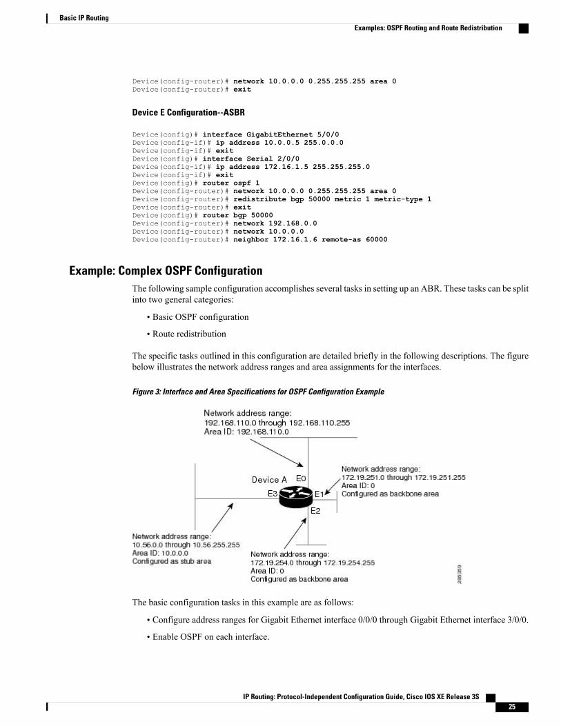
The specific tasks outlined in this configuration are detailed briefly in the following descriptions. The figurebelow illustrates the network address ranges and area assignments for the interfaces.
Figure 3: Interface and Area Specifications for OSPF Configuration Example
The basic configuration tasks in this example are as follows:
• Configure address ranges for Gigabit Ethernet interface 0/0/0 through Gigabit Ethernet interface 3/0/0.
• Enable OSPF on each interface.
IP Routing: Protocol-Independent Configuration Guide, Cisco IOS XE Release 3S 25
Basic IP RoutingExamples: OSPF Routing and Route Redistribution
• Set up an OSPF authentication password for each area and network.
• Assign link-state metrics and other OSPF interface configuration options.
• Create a stub area with area ID 10.0.0.0. (Note that the authentication and stub options of the arearouter configuration command are specified with separate area command entries, but they can be mergedinto a single area command.)
• Specify the backbone area (area 0).
Configuration tasks associated with redistribution are as follows:
• Redistribute the Enhanced Interior Gateway Routing Protocol (EIGRP) and the Routing InformationProtocol (RIP) into OSPF with various options set (including metric-type, metric, tag, and subnet).
• Redistribute EIGRP and OSPF into RIP.
The following is an example OSPF configuration:
Device(config)# interface GigabitEthernet 0/0/0Device(config-if)# ip address 192.168.110.201 255.255.255.0Device(config-if)# ip ospf authentication-key abcdefghDevice(config-if)# ip ospf cost 10Device(config-if)# exitDevice(config)# interface GigabitEthernet 1/0/0Device(config-if)# ip address 172.19.251.201 255.255.255.0Device(config-if)# ip ospf authentication-key ijklmnopDevice(config-if)# ip ospf cost 20Device(config-if)# ip ospf retransmit-interval 10Device(config-if)# ip ospf transmit-delay 2Device(config-if)# ip ospf priority 4Device(config-if)# exitDevice(config)# interface GigabitEthernet 2/0/0Device(config-if)# ip address 172.19.254.201 255.255.255.0Device(config-if)# ip ospf authentication-key abcdefghDevice(config-if)# ip ospf cost 10Device(config-if)# exitDevice(config)# interface GigabitEthernet 3/0/0Device(config-if)# ip address 10.56.0.201 255.255.0.0Device(config-if)# ip ospf authentication-key ijklmnopDevice(config-if)# ip ospf cost 20Device(config-if)# ip ospf dead-interval 80Device(config-if)# exitIn the following configuration, OSPF is on network 172.19.0.0:
Device(config)# router ospf 1Device(config-router)# network 10.0.0.0 0.255.255.255 area 10.0.0.0Device(config-router)# network 192.168.110.0 0.0.0.255 area 192.168.110.0Device(config-router)# network 172.19.0.0 0.0.255.255 area 0Device(config-router)# area 0 authenticationDevice(config-router)# area 10.0.0.0 stubDevice(config-router)# area 10.0.0.0 authenticationDevice(config-router)# area 10.0.0.0 default-cost 20Device(config-router)# area 192.168.110.0 authenticationDevice(config-router)# area 10.0.0.0 range 10.0.0.0 255.0.0.0Device(config-router)# area 192.168.110.0 range 192.168.110.0 255.255.255.0Device(config-router)# area 0 range 172.19.251.0 255.255.255.0Device(config-router)# area 0 range 172.19.254.0 255.255.255.0Device(config-router)# redistribute eigrp 200 metric-type 2 metric 1 tag 200 subnetsDevice(config-router)# redistribute rip metric-type 2 metric 1 tag 200Device(config-router)# exitIn the following configuration, EIGRP autonomous system 1 is on 172.19.0.0:
Device(config)# router eigrp 1
IP Routing: Protocol-Independent Configuration Guide, Cisco IOS XE Release 3S26
Basic IP RoutingExamples: OSPF Routing and Route Redistribution

Device(config-router)# network 172.19.0.0Device(config-router)# exitDevice(config)# ! RIP for 192.168.110.0:Device(config)# router ripDevice(config-router)# network 192.168.110.0Device(config-router)# redistribute eigrp 1 metric 1Device(config-router)# redistribute ospf 201 metric 1Device(config-router)# exit
Example: Default Metric Values RedistributionThe following example shows a device in autonomous system 1 that is configured to run both the RoutingInformation Protocol (RIP) and the Enhanced Interior Gateway Routing Protocol (EIGRP). The exampleadvertises EIGRP-derived routes using RIP and assigns the EIGRP-derived routes a RIP metric of 10.
Device(config)# router ripDevice(config-router)# redistribute eigrp 1Device(config-router)# default-metric 10Device(config-router)# exit
Examples: Redistribution With and Without Route MapsThe examples in this section illustrate the use of redistribution, with and without route maps. Examples fromboth the IP and Connectionless Network Service (CLNS) routing protocols are given. The following exampleredistributes all Open Shortest Path First (OSPF) routes into the Enhanced Interior Gateway Routing Protocol(EIGRP):
Device(config)# router eigrp 1Device(config-router)# redistribute ospf 101Device(config-router)# exitThe following example redistributes Routing Information Protocol (RIP) routes with a hop count equal to 1into OSPF. These routes will be redistributed into OSPF as external link state advertisements (LSAs) with ametric of 5, metric a type of type 1, and a tag equal to 1.
Device(config)# router ospf 1Device(config-router)# redistribute rip route-map rip-to-ospfDevice(config-router)# exitDevice(config)# route-map rip-to-ospf permitDevice(config-route-map)# match metric 1Device(config-route-map)# set metric 5Device(config-route-map)# set metric-type type 1Device(config-route-map)# set tag 1Device(config-route-map)# exitThe following example redistributes OSPF learned routes with tag 7 as a RIP metric of 15:
Device(config)# router ripDevice(config-router)# redistribute ospf 1 route-map 5Device(config-router)# exitDevice(config)# route-map 5 permitDevice(config-route-map)# match tag 7Device(config-route-map)# set metric 15The following example redistributes OSPF intra-area and interarea routes with next hop devices on serialinterface 0/0/0 into the Border Gateway Protocol (BGP) with an INTER_AS metric of 5:
Device(config)# router bgp 50000Device(config-router)# redistribute ospf 1 route-map 10Device(config-router)# exitDevice(config)# route-map 10 permit
IP Routing: Protocol-Independent Configuration Guide, Cisco IOS XE Release 3S 27
Basic IP RoutingExample: Default Metric Values Redistribution

Device(config-route-map)# match route-type internalDevice(config-route-map)# match interface serial 0/0/0Device(config-route-map)# set metric 5The following example redistributes two types of routes into the integrated IS-IS routing table (supportingboth IP and CLNS). The first type is OSPF external IP routes with tag 5; these routes are inserted into Level2 IS-IS link-state packets (LSPs) with a metric of 5. The second type is ISO-IGRP derived CLNS prefix routesthat match CLNS access list 2000; these routes will be redistributed into IS-IS as Level 2 LSPs with a metricof 30.
Device(config)# router isisDevice(config-router)# redistribute ospf 1 route-map 2Device(config-router)# redistribute iso-igrp nsfnet route-map 3
Device(config-router)# exitDevice(config)# route-map 2 permitDevice(config-route-map)# match route-type externalDevice(config-route-map)# match tag 5Device(config-route-map)# set metric 5Device(config-route-map)# set level level-2Device(config-route-map)# exitDevice(config)# route-map 3 permitDevice(config-route-map)# match address 2000Device(config-route-map)# set metric 30Device(config-route-map)# exitWith the following configuration, OSPF external routes with tags 1, 2, 3, and 5 are redistributed into RIP withmetrics of 1, 1, 5, and 5, respectively. The OSPF routes with a tag of 4 are not redistributed.
Device(config)# router ripDevice(config-router)# redistribute ospf 101 route-map 1Device(config-router)# exitDevice(config)# route-map 1 permitDevice(config-route-map)# match tag 1 2Device(config-route-map)# set metric 1Device(config-route-map)# exitDevice(config)# route-map 1 permitDevice(config-route-map)# match tag 3Device(config-route-map)# set metric 5Device(config-route-map)# exitDevice(config)# route-map 1 denyDevice(config-route-map)# match tag 4Device(config-route-map)# exitDevice(config)# route map 1 permitDevice(config-route-map)# match tag 5Device(config-route-map)# set metric 5Device(config-route-map)# exitGiven the following configuration, a RIP learned route for network 172.18.0.0 and an ISO-IGRP learned routewith prefix 49.0001.0002 will be redistributed into an IS-IS Level 2 LSP with a metric of 5:
Device(config)# router isisDevice(config-router)# redistribute rip route-map 1Device(config-router)# redistribute iso-igrp remote route-map 1Device(config-router)# exitDevice(config)# route-map 1 permitDevice(config-route-map)# match ip address 1Device(config-route-map)# match clns address 2Device(config-route-map)# set metric 5Device(config-route-map)# set level level-2Device(config-route-map)# exitDevice(config)# access-list 1 permit 172.18.0.0 0.0.255.255Device(config)# clns filter-set 2 permit 49.0001.0002...
IP Routing: Protocol-Independent Configuration Guide, Cisco IOS XE Release 3S28
Basic IP RoutingExamples: Redistribution With and Without Route Maps

The following configuration example illustrates how a route map is referenced by the default-informationrouter configuration command. This type of reference is called conditional default origination. OSPF willoriginate the default route (network 0.0.0.0) with a type 2 metric of 5 if 172.20.0.0 is in the routing table.
Device(config)# route-map ospf-default permitDevice(config-route-map)# match ip address 1Device(config-route-map)# set metric 5Device(config-route-map)# set metric-type type-2Device(config-route-map)# exitDevice(config)# access-list 1 172.20.0.0 0.0.255.255Device(config)# router ospf 101Device(config-router)# default-information originate route-map ospf-default
Examples: Key ManagementThe following example configures a key chain named chain1. In this example, the software always acceptsand sends key1 as a valid key. The key key2 is accepted from 1:30 p.m. to 3:30 p.m. and is sent from 2:00p.m. to 3:00 p.m. The overlap allows for migration of keys or discrepancy in the set time of the device.Likewise, the key key3 immediately follows key2, and there is 30-minutes on each side to handle time-of-daydifferences.
Device(config)# interface GigabitEthernet 0/0/0Device(config-if)# ip rip authentication key-chain chain1Device(config-if)# ip rip authentication mode md5Device(config-if)# exitDevice(config)# router ripDevice(config-router)# network 172.19.0.0Device(config-router)# version 2Device(config-router)# exitDevice(config)# key chain chain1Device(config-keychain)# key 1Device(config-keychain-key)# key-string key1Device(config-keychain-key)# exitDevice(config-keychain)# key 2Device(config-keychain-key)# key-string key2Device(config-keychain-key)# accept-lifetime 13:30:00 Jan 25 2005 duration 7200Device(config-keychain-key)# send-lifetime 14:00:00 Jan 25 2005 duration 3600Device(config-keychain-key)# exitDevice(config-keychain)# key 3Device(config-keychain-key)# key-string key3Device(config-keychain-key)# accept-lifetime 14:30:00 Jan 25 2005 duration 7200Device(config-keychain-key)# send-lifetime 15:00:00 Jan 25 2005 duration 3600Device(config-keychain-key)# endThe following example configures a key chain named chain1:
Device(config)# key chain chain1Device(config-keychain)# key 1Device(config-keychain-key)# key-string key1Device(config-keychain-key)# exitDevice(config-keychain)# key 2Device(config-keychain-key)# key-string key2Device(config-keychain-key)# accept-lifetime 00:00:00 Dec 5 2004 23:59:59 Dec 5 2005Device(config-keychain-key)# send-lifetime 06:00:00 Dec 5 2004 18:00:00 Dec 5 2005Device(config-keychain-key)# exitDevice(config-keychain)# exitDevice(config)# interface GigabitEthernet 0/0/0Device(config-if)# ip address 172.19.104.75 255.255.255.0 secondary 172.19.232.147255.255.255.240Device(config-if)# ip rip authentication key-chain chain1Device(config-if)# media-type 10BaseTDevice(config-if)# exitDevice(config)# interface GigabitEthernet 1/0/0Device(config-if)# no ip address
IP Routing: Protocol-Independent Configuration Guide, Cisco IOS XE Release 3S 29
Basic IP RoutingExamples: Key Management

Device(config-if)# shutdownDevice(config-if)# media-type 10BaseTDevice(config-if)# exitDevice(config)# interface Fddi 0Device(config-if)# ip address 10.1.1.1 255.255.255.0Device(config-if)# no keepaliveDevice(config-if)# exitDevice(config)# interface Fddi 1/0/0Device(config-if)# ip address 172.16.1.1 255.255.255.0Device(config-if)# ip rip send version 1Device(config-if)# ip rip receive version 1Device(config-if)# no keepaliveDevice(config-if)# exitDevice(config)# router ripDevice(config-router)# version 2Device(config-router)# network 172.19.0.0Device(config-router)# network 10.0.0.0Device(config-router)# network 172.16.0.0
Additional ReferencesRelated Documents
Document TitleRelated Topic
Cisco IOS Master Command List, All ReleasesCisco IOS commands
Cisco IOS IP Routing: Protocol-IndependentCommand Reference
IP routing protocol-independent commands
Technical Assistance
LinkDescription
http://www.cisco.com/cisco/web/support/index.htmlThe Cisco Support and Documentation websiteprovides online resources to download documentation,software, and tools. Use these resources to install andconfigure the software and to troubleshoot and resolvetechnical issues with Cisco products and technologies.Access to most tools on the Cisco Support andDocumentation website requires a Cisco.com user IDand password.
Feature Information for Basic IP RoutingThe following table provides release information about the feature or features described in this module. Thistable lists only the software release that introduced support for a given feature in a given software releasetrain. Unless noted otherwise, subsequent releases of that software release train also support that feature.
Use Cisco Feature Navigator to find information about platform support and Cisco software image support.To access Cisco Feature Navigator, go to . An account on Cisco.com is not required.
IP Routing: Protocol-Independent Configuration Guide, Cisco IOS XE Release 3S30
Basic IP RoutingAdditional References

Table 2: Feature Information for Basic IP Routing
Feature InformationReleasesFeature Name
The IP Routing feature introducedbasic IP routing features that aredocumented throughout thismodule and also in other IPRouting Protocol modules.
IP Routing
IP Routing: Protocol-Independent Configuration Guide, Cisco IOS XE Release 3S 31
Basic IP RoutingFeature Information for Basic IP Routing

IP Routing: Protocol-Independent Configuration Guide, Cisco IOS XE Release 3S32
Basic IP RoutingFeature Information for Basic IP Routing

C H A P T E R 2IPv6 Routing: Static Routing
This feature provides static routing for IPv6. Static routes are manually configured and define an explicitpath between two networking devices.
• Finding Feature Information, page 33
• Prerequisites for IPv6 Routing: Static Routing, page 33
• Restrictions for IPv6 Routing: Static Routing, page 34
• Information About IPv6 Routing: Static Routing, page 34
• How to Configure IPv6 Static Routing, page 36
• Configuration Examples for IPv6 Static Routing, page 40
• Additional References, page 42
• Feature Information for IPv6 Routing: Static Routing, page 43
Finding Feature InformationYour software release may not support all the features documented in this module. For the latest caveats andfeature information, see Bug Search Tool and the release notes for your platform and software release. Tofind information about the features documented in this module, and to see a list of the releases in which eachfeature is supported, see the feature information table.
Use Cisco Feature Navigator to find information about platform support and Cisco software image support.To access Cisco Feature Navigator, go to www.cisco.com/go/cfn. An account on Cisco.com is not required.
Prerequisites for IPv6 Routing: Static RoutingBefore configuring the device with a static IPv6 route, you must enable the forwarding of IPv6 packets usingthe ipv6 unicast-routing global configuration command, enable IPv6 on at least one interface, and configurean IPv6 address on that interface.
IP Routing: Protocol-Independent Configuration Guide, Cisco IOS XE Release 3S 33
Restrictions for IPv6 Routing: Static Routing• IPv6 static routes do not support the tag and permanent keywords of the IPv4 ip route command.
• IPv6 does not support inserting static routes into virtual routing and forwarding (VRF) tables.
• You should not configure static configurations over dynamic interfaces, because static configurationswill be lost during reboot or when the user disconnects and reconnects the device.
Information About IPv6 Routing: Static Routing
Static RoutesNetworking devices forward packets using route information that is either manually configured or dynamicallylearned using a routing protocol. Static routes are manually configured and define an explicit path betweentwo networking devices. Unlike a dynamic routing protocol, static routes are not automatically updated andmust be manually reconfigured if the network topology changes. The benefits of using static routes includesecurity and resource efficiency. Static routes use less bandwidth than dynamic routing protocols and no CPUcycles are used to calculate and communicate routes. The main disadvantage to using static routes is the lackof automatic reconfiguration if the network topology changes.
Static routes can be redistributed into dynamic routing protocols but routes generated by dynamic routingprotocols cannot be redistributed into the static routing table. No algorithm exists to prevent the configurationof routing loops that use static routes.
Static routes are useful for smaller networks with only one path to an outside network and to provide securityfor a larger network for certain types of traffic or links to other networks that need more control. In general,most networks use dynamic routing protocols to communicate between networking devices but may have oneor two static routes configured for special cases.
Directly Attached Static RoutesIn directly attached static routes, only the output interface is specified. The destination is assumed to be directlyattached to this interface, so the packet destination is used as the next-hop address. This example shows sucha definition:
ipv6 route 2001:DB8::/32 gigabitethernet1/0/0The example specifies that all destinations with address prefix 2001:DB8::/32 are directly reachable throughinterface GigabitEthernet1/0/0.
Directly attached static routes are candidates for insertion in the IPv6 routing table only if they refer to a validIPv6 interface; that is, an interface that is both up and has IPv6 enabled on it.
IP Routing: Protocol-Independent Configuration Guide, Cisco IOS XE Release 3S34
IPv6 Routing: Static RoutingRestrictions for IPv6 Routing: Static Routing
Recursive Static RoutesIn a recursive static route, only the next hop is specified. The output interface is derived from the next hop.This example shows such a definition:
ipv6 route 2001:DB8::/32 2001:DB8:3000:1This example specifies that all destinations with address prefix 2001:DB8::/32 are reachable via the host withaddress 2001:DB8:3000:1.
A recursive static route is valid (that is, it is a candidate for insertion in the IPv6 routing table) only when thespecified next hop resolves, either directly or indirectly, to a valid IPv6 output interface, provided the routedoes not self-recurse, and the recursion depth does not exceed the maximum IPv6 forwarding recursion depth.
A route self-recurses if it is itself used to resolve its own next hop. For example, suppose we have the followingroutes in the IPv6 routing table:
IPv6 Routing Table - 9 entriesCodes: C - Connected, L - Local, S - Static, R - RIP, B - BGP
U - Per-user Static routeI1 - ISIS L1, I2 - ISIS L2, IA - ISIS interareaO - OSPF intra, OI - OSPF inter, OE1 - OSPF ext 1, OE2 - OSPF ext 2
R 2001:DB8::/32 [130/0]via ::, Serial2/0
B 2001:DB8:3000:0/16 [200/45]Via 2001:DB8::0104
The following examples defines a recursive IPv6 static route:
ipv6 route2001:DB8::/32 2001:0BD8:3000:1This static route will not be inserted into the IPv6 routing table because it is self-recursive. The next hop ofthe static route, 2001:DB8:3000:1, resolves via the BGP route 2001:DB8:3000:0/16, which is itself a recursiveroute (that is, it only specifies a next hop). The next hop of the BGP route, 2001:DB8::0104, resolves via thestatic route. Therefore, the static route would be used to resolve its own next hop.
It is not normally useful to manually configure a self-recursive static route, although it is not prohibited.However, a recursive static route that has been inserted in the IPv6 routing table may become self-recursiveas a result of some transient change in the network learned through a dynamic routing protocol. If this occurs,the fact that the static route has become self-recursive will be detected and it will be removed from the IPv6routing table, although not from the configuration. A subsequent network change may cause the static routeto no longer be self-recursive, in which case it will be reinserted in the IPv6 routing table.
Fully Specified Static RoutesIn a fully specified static route, both the output interface and the next hop are specified. This form of staticroute is used when the output interface is a multi-access one and it is necessary to explicitly identify the nexthop. The next hop must be directly attached to the specified output interface. The following example showsa definition of a fully specified static route:
ipv6 route 2001:DB8:/32 gigabitethernet1/0/0 2001:DB8:3000:1A fully specified route is valid (that is, a candidate for insertion into the IPv6 routing table) when the specifiedIPv6 interface is IPv6-enabled and up.
IP Routing: Protocol-Independent Configuration Guide, Cisco IOS XE Release 3S 35
IPv6 Routing: Static RoutingRecursive Static Routes
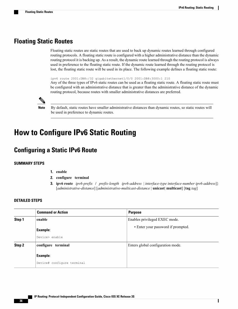
Floating Static RoutesFloating static routes are static routes that are used to back up dynamic routes learned through configuredrouting protocols. A floating static route is configured with a higher administrative distance than the dynamicrouting protocol it is backing up. As a result, the dynamic route learned through the routing protocol is alwaysused in preference to the floating static route. If the dynamic route learned through the routing protocol islost, the floating static route will be used in its place. The following example defines a floating static route:
ipv6 route 2001:DB8:/32 gigabitethernet1/0/0 2001:DB8:3000:1 210Any of the three types of IPv6 static routes can be used as a floating static route. A floating static route mustbe configured with an administrative distance that is greater than the administrative distance of the dynamicrouting protocol, because routes with smaller administrative distances are preferred.
By default, static routes have smaller administrative distances than dynamic routes, so static routes willbe used in preference to dynamic routes.
Note
How to Configure IPv6 Static Routing
Configuring a Static IPv6 Route
SUMMARY STEPS
1. enable2. configure terminal3. ipv6 route ipv6-prefix / prefix-length ipv6-address | interface-type interface-number ipv6-address]}
[administrative-distance] [administrative-multicast-distance | unicast|multicast] [tag tag]
DETAILED STEPS
PurposeCommand or Action
Enables privileged EXEC mode.enableStep 1
Example:
Device> enable
• Enter your password if prompted.
Enters global configuration mode.configure terminal
Example:
Device# configure terminal
Step 2
IP Routing: Protocol-Independent Configuration Guide, Cisco IOS XE Release 3S36
IPv6 Routing: Static RoutingFloating Static Routes
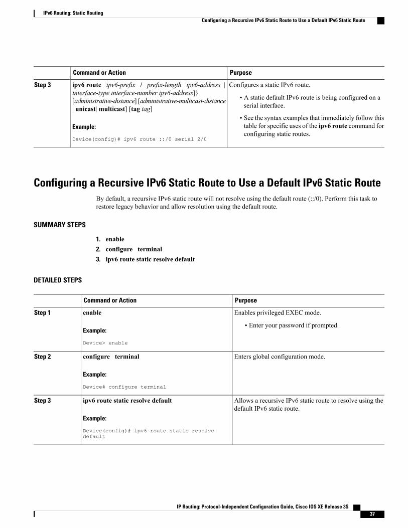
PurposeCommand or Action
Configures a static IPv6 route.ipv6 route ipv6-prefix / prefix-length ipv6-address |interface-type interface-number ipv6-address]}
Step 3
• A static default IPv6 route is being configured on aserial interface.
[administrative-distance] [administrative-multicast-distance| unicast|multicast] [tag tag]
Example:
Device(config)# ipv6 route ::/0 serial 2/0
• See the syntax examples that immediately follow thistable for specific uses of the ipv6 route command forconfiguring static routes.
Configuring a Recursive IPv6 Static Route to Use a Default IPv6 Static RouteBy default, a recursive IPv6 static route will not resolve using the default route (::/0). Perform this task torestore legacy behavior and allow resolution using the default route.
SUMMARY STEPS
1. enable2. configure terminal3. ipv6 route static resolve default
DETAILED STEPS
PurposeCommand or Action
Enables privileged EXEC mode.enableStep 1
Example:
Device> enable
• Enter your password if prompted.
Enters global configuration mode.configure terminal
Example:
Device# configure terminal
Step 2
Allows a recursive IPv6 static route to resolve using thedefault IPv6 static route.
ipv6 route static resolve default
Example:
Device(config)# ipv6 route static resolvedefault
Step 3
IP Routing: Protocol-Independent Configuration Guide, Cisco IOS XE Release 3S 37
IPv6 Routing: Static RoutingConfiguring a Recursive IPv6 Static Route to Use a Default IPv6 Static Route

Configuring a Floating Static IPv6 Route
SUMMARY STEPS
1. enable2. configure terminal3. ipv6 route ipv6-prefix / prefix-length {ipv6-address | interface-type interface-number ipv6-address]}
[administrative-distance] [administrative-multicast-distance | unicast |multicast] [tag tag]
DETAILED STEPS
PurposeCommand or Action
Enables privileged EXEC mode.enableStep 1
Example:
Device> enable
• Enter your password if prompted.
Enters global configuration mode.configure terminal
Example:
Device# configure terminal
Step 2
Configures a static IPv6 route.ipv6 route ipv6-prefix / prefix-length{ipv6-address | interface-type interface-number
Step 3
• In this example, a floating static IPv6 route is being configured.ipv6-address]} [administrative-distance][administrative-multicast-distance | unicast |multicast] [tag tag]
• Default administrative distances are as follows:
• Connected interface--0
Example:
Device(config)# ipv6 route 2001:DB8::/32serial 2/0 201
• Static route--1
• Enhanced Interior Gateway Routing Protocol (EIGRP)summary route--5
• External Border Gateway Protocol (eBGP)--20
• Internal Enhanced IGRP--90
• IGRP--100
• Open Shortest Path First--110
• Intermediate System-to-Intermediate System (IS-IS)--115
• Routing Information Protocol (RIP)--120
• Exterior Gateway Protocol (EGP)--140
• EIGRP external route--170
• Internal BGP--200
IP Routing: Protocol-Independent Configuration Guide, Cisco IOS XE Release 3S38
IPv6 Routing: Static RoutingConfiguring a Floating Static IPv6 Route

PurposeCommand or Action
• Unknown--255
Verifying Static IPv6 Route Configuration and Operation
SUMMARY STEPS
1. enable2. Do one of the following:
• show ipv6 static [ipv6-address | ipv6-prefix / prefix-length][interface interface-typeinterface-number] [recursive] [detail]
• show ipv6 route [ipv6-address | ipv6-prefix / prefix-length | protocol | interface-typeinterface-number]
3. debug ipv6 routing
DETAILED STEPS
PurposeCommand or Action
Enables privileged EXEC mode.enableStep 1
Example:
Device> enable
• Enter your password if prompted.
Displays the current contents of the IPv6 routing table.Do one of the following:Step 2
• show ipv6 static [ipv6-address | ipv6-prefix /prefix-length][interface interface-type interface-number][recursive] [detail]
• These examples show two different ways ofdisplaying IPv6 static routes.
• show ipv6 route [ipv6-address | ipv6-prefix / prefix-length| protocol | interface-type interface-number]
Example:
Device# show ipv6 static
Example:
Device# show ipv6 route static
IP Routing: Protocol-Independent Configuration Guide, Cisco IOS XE Release 3S 39
IPv6 Routing: Static RoutingVerifying Static IPv6 Route Configuration and Operation

PurposeCommand or Action
Displays debugging messages for IPv6 routing tableupdates and route cache updates.
debug ipv6 routing
Example:
Device# debug ipv6 routing
Step 3
Configuration Examples for IPv6 Static RoutingStatic routes may be used for a variety of purposes. Common usages include the following:
• Manual summarization
• Traffic discard
• Fixed default route
• Backup route
In many cases, alternative mechanisms exist within Cisco software to achieve the same objective. Whetherto use static routes or one of the alternative mechanisms depends on local circumstances.
Example Configuring Manual SummarizationThe following example shows a static route being used to summarize local interface prefixes advertised intoRIP. The static route also serves as a discard route, discarding any packets received by the router to a2001:DB8:1::/48 destination not covered by a more specific interface prefix.
Router> enableRouter# configure terminalEnter configuration commands, one per line. End with CNTL/Z.Router(config)# interface gigabitethernet0/0/0Router(config-if)# ipv6 address 2001:DB8:2:1234/64Router(config-if)# exitRouter(config)#Router(config)# interface gigabitethernet1/0/0Router(config-if)# ipv6 address 2001:DB8:3:1234/64Router(config-if)# exitRouter(config)#Router(config)# interface gigabitethernet2/0/0Router(config-if)# ipv6 address 2001:DB8:4:1234/64Router(config-if)# exitRouter(config)#Router(config)# interface gigabitethernet3/0/0Router(config-if)# ipv6 address 2001:DB8::1234/64Router(config-if)# ipv6 rip one enableRouter(config-if)# exitRouter(config)#Router(config)# ipv6 router rip oneRouter(config-rtr)# redistribute staticRouter(config-rtr)# exitRouter(config)#Router(config)# ipv6 route 2001:DB8:1:1/48 null0
IP Routing: Protocol-Independent Configuration Guide, Cisco IOS XE Release 3S40
IPv6 Routing: Static RoutingConfiguration Examples for IPv6 Static Routing

Router(config)# endRouter#00:01:30: %SYS-5-CONFIG_I: Configured from console by consoleRouter# show ipv6 route static
IPv6 Routing Table - 3 entriesCodes: C - Connected, L - Local, S - Static, R - RIP, B - BGP
U - Per-user Static routeI1 - ISIS L1, I2 - ISIS L2, IA - ISIS interarea, IS - ISIS summaryO - OSPF intra, OI - OSPF inter, OE1 - OSPF ext 1, OE2 - OSPF ext 2ON1 - OSPF NSSA ext 1, ON2 - OSPF NSSA ext 2
S 2001:DB8:1::/48 [1/0]via ::, Null0
Example: Configuring Traffic DiscardConfiguring a static route to point at interface null0 may be used for discarding traffic to a particular prefix.For example, if it is required to discard all traffic to prefix 2001:DB8:42:1/64, the following static route wouldbe defined:
Device> enableDevice# configureterminalEnter configuration commands, one per line. End with CNTL/Z.Device(config)# ipv6 route 2001:DB8:42:1::/64 null0Device(config)# end
Example: Configuring a Fixed Default RouteA default static route is often used in simple router topologies. In the following example, a router is connectedto its local site via GigabitEthernet 0/0/0 and to the main corporate network via Serial 2/0/0 and Serial 3/0/0.All nonlocal traffic will be routed over the two serial interfaces.
Router(config)# interface gigabitethernet0/0/0Router(config-if)# ipv6 address 2001:DB8:17:1234/64Router(config-if)# exitRouter(config)# interface Serial2/0/0Router(config-if)# ipv6 address 2001:DB8:1:1234/64Router(config-if)# exitRouter(config)# interface Serial3/0/0Router(config-if)# ipv6 address 2001:DB8:2:124/64Router(config-if)# exitRouter(config)# ipv6 route ::/0 Serial2/0Router(config)# ipv6 route ::/0 Serial3/0Router(config)# endRouter#00:06:30: %SYS-5-CONFIG_I: Configured from console by consoleRouter# show ipv6 route staticIPv6 Routing Table - 7 entriesCodes: C - Connected, L - Local, S - Static, R - RIP, B - BGP
U - Per-user Static routeI1 - ISIS L1, I2 - ISIS L2, IA - ISIS interarea, IS - ISIS summaryO - OSPF intra, OI - OSPF inter, OE1 - OSPF ext 1, OE2 - OSPF ext 2ON1 - OSPF NSSA ext 1, ON2 - OSPF NSSA ext 2
S ::/0 [1/0]via ::, Serial2/0via ::, Serial3/0
IP Routing: Protocol-Independent Configuration Guide, Cisco IOS XE Release 3S 41
IPv6 Routing: Static RoutingExample: Configuring Traffic Discard

Example: Configuring a Floating Static RouteA floating static route often is used to provide a backup path in the event of connectivity failure. In thefollowing example, the router has connectivity to the network core via GigabitEthernet0/0/0 and learns theroute 2001:DB8:1:1/32 via IS-IS. If the GigabitEthernet0/0/0 interface fails, or if route 2001:DB8:1:1/32 isno longer learned via IS-IS (indicating loss of connectivity elsewhere in the network), traffic is routed via thebackup ISDN interface.
Router> enableRouter# configureterminalEnter configuration commands, one per line. End with CNTL/Z.Router(config)# interface gigabitethernet0/0/0Router(config-if)# ipv6 address 2001:DB8:17:1234/64Router(config-if)# exitRouter(config)# interface gigabitethernet0/0/0Router(config-if)# ipv6 address 2001:DB8:1:1234/64Router(config-if)# ipv6routerisisRouter(config-if)# exitRouter(config)# router isisRouter(config-router)# net 42.0000.0000.0000.0001.00Router(config-router)# exitRouter(config)# interface BRI1/0Router(config-if)# encapsulation pppRouter(config-if)# ipv6 enableRouter(config-if)# isdn switch-type basic-net3Router(config-if)# ppp authentication chap optionalRouter(config-if)# ppp multilinkRouter(config-if)# exitRouter(config)# dialer-list 1 protocol ipv6 permitRouter(config)# ipv6 route 2001:DB8:1::/32 BRI1/0 200Router(config)# endRouter#00:03:07: %SYS-5-CONFIG_I: Configured from console by console
Additional ReferencesRelated Documents
Document TitleRelated Topic
IPv6 Configuration GuideIPv6 addressing and connectivity
Cisco IOSMaster Commands List,All Releases
Cisco IOS commands
Cisco IOS IPv6 CommandReference
IPv6 commands
Cisco IOS IPv6 Feature MappingCisco IOS IPv6 features
IP Routing: Protocol-Independent Configuration Guide, Cisco IOS XE Release 3S42
IPv6 Routing: Static RoutingExample: Configuring a Floating Static Route

Standards and RFCs
TitleStandard/RFC
IPv6 RFCsRFCs for IPv6
MIBs
MIBs LinkMIB
To locate and downloadMIBs for selected platforms,Cisco IOS releases, and feature sets, use Cisco MIBLocator found at the following URL:
http://www.cisco.com/go/mibs
Technical Assistance
LinkDescription
http://www.cisco.com/cisco/web/support/index.htmlThe Cisco Support and Documentation websiteprovides online resources to download documentation,software, and tools. Use these resources to install andconfigure the software and to troubleshoot and resolvetechnical issues with Cisco products and technologies.Access to most tools on the Cisco Support andDocumentation website requires a Cisco.com user IDand password.
Feature Information for IPv6 Routing: Static RoutingThe following table provides release information about the feature or features described in this module. Thistable lists only the software release that introduced support for a given feature in a given software releasetrain. Unless noted otherwise, subsequent releases of that software release train also support that feature.
Use Cisco Feature Navigator to find information about platform support and Cisco software image support.To access Cisco Feature Navigator, go to . An account on Cisco.com is not required.
IP Routing: Protocol-Independent Configuration Guide, Cisco IOS XE Release 3S 43
IPv6 Routing: Static RoutingFeature Information for IPv6 Routing: Static Routing

Table 3: Feature Information for IPv6 Routing: Static Routing
Feature InformationReleasesFeature Name
Static routes are manuallyconfigured and define an explicitpath between two networkingdevices.
The following commands wereintroduced ormodified: ipv6 route,ipv6 route static resolve default,show ipv6 route, show ipv6 static.
12.0(22)S
12.2(2)T
12.2(14)S
12.2(17a)SX1
12.2(25)SG
12.2(28)SB
12.2(33)SRA
Cisco IOS XE Release 2.1
IPv6 Routing: Static Routing
IP Routing: Protocol-Independent Configuration Guide, Cisco IOS XE Release 3S44
IPv6 Routing: Static RoutingFeature Information for IPv6 Routing: Static Routing

C H A P T E R 3IPv4 Loop-Free Alternate Fast Reroute
When a link or a router fails, distributed routing algorithms compute new routes that take into account thefailure. The time taken for computation is called routing transition. Until the transition is complete and allrouters are converged on a common view of the network, the connectivity between the source and destinationpairs is interrupted. You can use the IPv4 Loop-Free Alternate Fast Reroute feature to reduce the routingtransition time to less than 50 milliseconds using a precomputed alternate next hop. When a router is notifiedof a link failure, the router immediately switches over to the repair path to reduce traffic loss.
IPv4 Loop-Free Alternate Fast Reroute supports the precomputation of repair paths. The repair pathcomputation is done by the Intermediate System-to-Intermediate System (IS-IS) routing protocol, and theresulting repair paths are sent to the Routing Information Base (RIB). The repair path installation is done byCisco Express Forwarding (formerly known as CEF) and Open Shortest Path First (OSPF).
• Finding Feature Information, page 45
• Prerequisites for IPv4 Loop-Free Alternate Fast Reroute, page 46
• Restrictions for IPv4 Loop-Free Alternate Fast Reroute, page 46
• Information About IPv4 Loop-Free Alternate Fast Reroute, page 47
• How to Configure IPv4 Loop-Free Alternate Fast Reroute, page 49
• Configuration Examples for IPv4 Loop-Free Alternate Fast Reroute, page 52
• Additional References, page 53
• Feature Information for Configuring IPv4 Loop-Free Alternate Fast Reroute, page 54
Finding Feature InformationYour software release may not support all the features documented in this module. For the latest caveats andfeature information, see Bug Search Tool and the release notes for your platform and software release. Tofind information about the features documented in this module, and to see a list of the releases in which eachfeature is supported, see the feature information table.
Use Cisco Feature Navigator to find information about platform support and Cisco software image support.To access Cisco Feature Navigator, go to www.cisco.com/go/cfn. An account on Cisco.com is not required.
IP Routing: Protocol-Independent Configuration Guide, Cisco IOS XE Release 3S 45
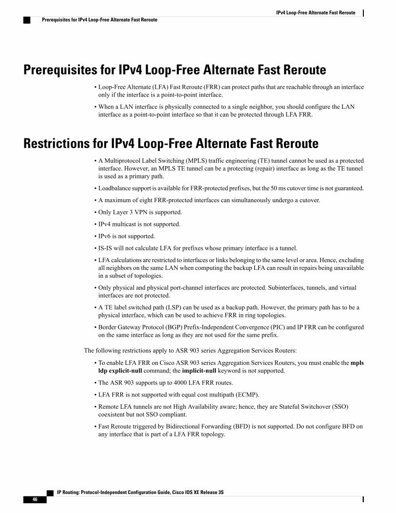
Prerequisites for IPv4 Loop-Free Alternate Fast Reroute• Loop-Free Alternate (LFA) Fast Reroute (FRR) can protect paths that are reachable through an interfaceonly if the interface is a point-to-point interface.
• When a LAN interface is physically connected to a single neighbor, you should configure the LANinterface as a point-to-point interface so that it can be protected through LFA FRR.
Restrictions for IPv4 Loop-Free Alternate Fast Reroute• AMultiprotocol Label Switching (MPLS) traffic engineering (TE) tunnel cannot be used as a protectedinterface. However, an MPLS TE tunnel can be a protecting (repair) interface as long as the TE tunnelis used as a primary path.
• Loadbalance support is available for FRR-protected prefixes, but the 50ms cutover time is not guaranteed.
• A maximum of eight FRR-protected interfaces can simultaneously undergo a cutover.
• Only Layer 3 VPN is supported.
• IPv4 multicast is not supported.
• IPv6 is not supported.
• IS-IS will not calculate LFA for prefixes whose primary interface is a tunnel.
• LFA calculations are restricted to interfaces or links belonging to the same level or area. Hence, excludingall neighbors on the same LAN when computing the backup LFA can result in repairs being unavailablein a subset of topologies.
• Only physical and physical port-channel interfaces are protected. Subinterfaces, tunnels, and virtualinterfaces are not protected.
• A TE label switched path (LSP) can be used as a backup path. However, the primary path has to be aphysical interface, which can be used to achieve FRR in ring topologies.
• Border Gateway Protocol (BGP) Prefix-Independent Convergence (PIC) and IP FRR can be configuredon the same interface as long as they are not used for the same prefix.
The following restrictions apply to ASR 903 series Aggregation Services Routers:
• To enable LFA FRR on Cisco ASR 903 series Aggregation Services Routers, you must enable themplsldp explicit-null command; the implicit-null keyword is not supported.
• The ASR 903 supports up to 4000 LFA FRR routes.
• LFA FRR is not supported with equal cost multipath (ECMP).
• Remote LFA tunnels are not High Availability aware; hence, they are Stateful Switchover (SSO)coexistent but not SSO compliant.
• Fast Reroute triggered by Bidirectional Forwarding (BFD) is not supported. Do not configure BFD onany interface that is part of a LFA FRR topology.
IP Routing: Protocol-Independent Configuration Guide, Cisco IOS XE Release 3S46
IPv4 Loop-Free Alternate Fast ReroutePrerequisites for IPv4 Loop-Free Alternate Fast Reroute

Information About IPv4 Loop-Free Alternate Fast Reroute
IS-IS and IP FRRWhen a local link fails in a network, IS-IS recomputes new primary next-hop routes for all affected prefixes.These prefixes are updated in the RIB and the Forwarding Information Base (FIB). Until the primary prefixesare updated in the forwarding plane, traffic directed towards the affected prefixes are discarded. This processcan take hundreds of milliseconds.
In IP FRR, IS-IS computes LFA next-hop routes for the forwarding plane to use in case of primary pathfailures. LFA is computed per prefix.
When there are multiple LFAs for a given primary path, IS-IS uses a tiebreaking rule to pick a single LFAfor a primary path. In case of a primary path with multiple LFA paths, prefixes are distributed equally amongLFA paths.
Repair PathsRepair paths forward traffic during a routing transition. When a link or a router fails, due to the loss of aphysical layer signal, initially, only the neighboring routers are aware of the failure. All other routers in thenetwork are unaware of the nature and location of this failure until information about this failure is propagatedthrough a routing protocol, which may take several hundred milliseconds. It is, therefore, necessary to arrangefor packets affected by the network failure to be steered to their destinations.
A router adjacent to the failed link employs a set of repair paths for packets that would have used the failedlink. These repair paths are used from the time the router detects the failure until the routing transition iscomplete. By the time the routing transition is complete, all routers in the network revise their forwardingdata and the failed link is eliminated from the routing computation.
Repair paths are precomputed in anticipation of failures so that they can be activated the moment a failure isdetected.
The IPv4 LFA FRR feature uses the following repair paths:
• Equal Cost Multipath (ECMP) uses a link as a member of an equal cost path-split set for a destination.The other members of the set can provide an alternative path when the link fails.
• LFA is a next-hop route that delivers a packet to its destination without looping back. Downstream pathsare a subset of LFAs.
LFA OverviewLFA is a node other than the primary neighbor. Traffic is redirected to an LFA after a network failure. AnLFA makes the forwarding decision without any knowledge of the failure.
An LFA must neither use a failed element nor use a protecting node to forward traffic. An LFA must notcause loops. By default, LFA is enabled on all supported interfaces as long as the interface can be used as aprimary path.
Advantages of using per-prefix LFAs are as follows:
IP Routing: Protocol-Independent Configuration Guide, Cisco IOS XE Release 3S 47
IPv4 Loop-Free Alternate Fast RerouteInformation About IPv4 Loop-Free Alternate Fast Reroute

• The repair path forwards traffic during transition when the primary path link is down.
• All destinations having a per-prefix LFA are protected. This leaves only a subset (a node at the far sideof the failure) unprotected.
LFA CalculationThe general algorithms to compute per-prefix LFAs can be found in RFC 5286. IS-IS implements RFC 5286with a small change to reduce memory usage. Instead of performing a Shortest Path First (SPF) calculationfor all neighbors before examining prefixes for protection, IS-IS examines prefixes after SPF calculation isperformed for each neighbor. Because IS-IS examines prefixes after SPF calculation is performed, IS-ISretains the best repair path after SPF calculation is performed for each neighbor. IS-IS does not have to saveSPF results for all neighbors.
Interaction Between RIB and Routing ProtocolsA routing protocol computes repair paths for prefixes by implementing tiebreaking algorithms. The end resultof the computation is a set of prefixes with primary paths, where some primary paths are associated with repairpaths.
A tiebreaking algorithm considers LFAs that satisfy certain conditions or have certain attributes. When thereis more than one LFA, configure the fast-reroute per-prefix command with the tie-break keyword. If a ruleeliminates all candidate LFAs, then the rule is skipped.
A primary path can have multiple LFAs. A routing protocol is required to implement default tiebreaking rulesand to allow you to modify these rules. The objective of the tiebreaking algorithm is to eliminate multiplecandidate LFAs, select one LFA per primary path per prefix, and distribute the traffic over multiple candidateLFAs when the primary path fails.
Tiebreaking rules cannot eliminate all candidates.
The following attributes are used for tiebreaking:
• Downstream—Eliminates candidates whose metric to the protected destination is lower than the metricof the protecting node to the destination.
• Linecard-disjoint—Eliminates candidates sharing the same linecard with the protected path.
• Shared Risk Link Group (SRLG)—Eliminates candidates that belong to one of the protected path SRLGs.
• Load-sharing—Distributes remaining candidates among prefixes sharing the protected path.
• Lowest-repair-path-metric—Eliminates candidates whose metric to the protected prefix is higher.
• Node protecting—Eliminates candidates that are not node protected.
• Primary-path—Eliminates candidates that are not ECMPs.
• Secondary-path—Eliminates candidates that are ECMPs.
IP Routing: Protocol-Independent Configuration Guide, Cisco IOS XE Release 3S48
IPv4 Loop-Free Alternate Fast RerouteLFA Calculation

How to Configure IPv4 Loop-Free Alternate Fast Reroute
Configuring Fast Reroute Support
LFA computations are enabled for all routes, and FRR is enabled on all supported interfaces.Note
SUMMARY STEPS
1. enable2. configure terminal3. interface type number4. ip address ip-address mask5. ip router isis area-tag6. isis tag tag-number7. exit8. interface type number9. ip address ip-address mask10. ip router isis area-tag11. isis tag tag-number12. exit13. router isis area-tag14. net net15. fast-reroute per-prefix {level-1 | level-2} {all | route-map route-map-name}16. end
DETAILED STEPS
PurposeCommand or Action
Enables privileged EXEC mode.enable
Example:Device> enable
Step 1
• Enter your password if prompted.
Enters global configuration mode.configure terminal
Example:Device# configure terminal
Step 2
IP Routing: Protocol-Independent Configuration Guide, Cisco IOS XE Release 3S 49
IPv4 Loop-Free Alternate Fast RerouteHow to Configure IPv4 Loop-Free Alternate Fast Reroute
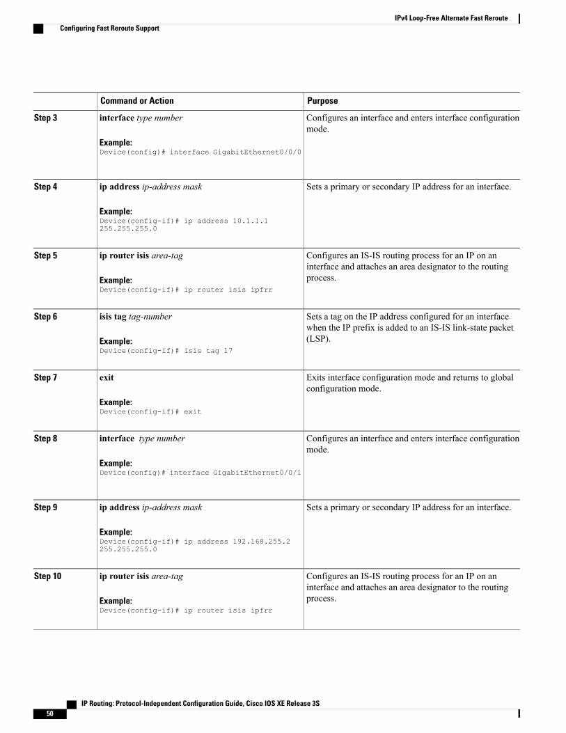
PurposeCommand or Action
Configures an interface and enters interface configurationmode.
interface type number
Example:Device(config)# interface GigabitEthernet0/0/0
Step 3
Sets a primary or secondary IP address for an interface.ip address ip-address mask
Example:Device(config-if)# ip address 10.1.1.1255.255.255.0
Step 4
Configures an IS-IS routing process for an IP on aninterface and attaches an area designator to the routingprocess.
ip router isis area-tag
Example:Device(config-if)# ip router isis ipfrr
Step 5
Sets a tag on the IP address configured for an interfacewhen the IP prefix is added to an IS-IS link-state packet(LSP).
isis tag tag-number
Example:Device(config-if)# isis tag 17
Step 6
Exits interface configuration mode and returns to globalconfiguration mode.
exit
Example:Device(config-if)# exit
Step 7
Configures an interface and enters interface configurationmode.
interface type number
Example:Device(config)# interface GigabitEthernet0/0/1
Step 8
Sets a primary or secondary IP address for an interface.ip address ip-address mask
Example:Device(config-if)# ip address 192.168.255.2255.255.255.0
Step 9
Configures an IS-IS routing process for an IP on aninterface and attaches an area designator to the routingprocess.
ip router isis area-tag
Example:Device(config-if)# ip router isis ipfrr
Step 10
IP Routing: Protocol-Independent Configuration Guide, Cisco IOS XE Release 3S50
IPv4 Loop-Free Alternate Fast RerouteConfiguring Fast Reroute Support
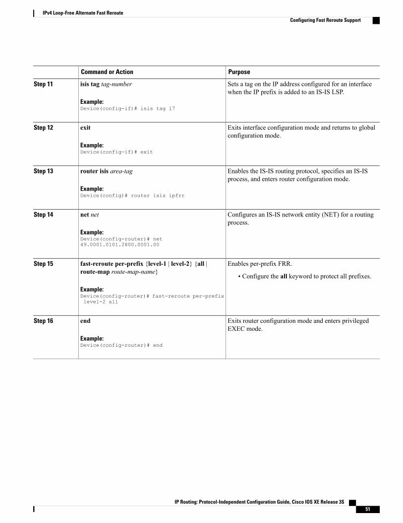
PurposeCommand or Action
Sets a tag on the IP address configured for an interfacewhen the IP prefix is added to an IS-IS LSP.
isis tag tag-number
Example:Device(config-if)# isis tag 17
Step 11
Exits interface configuration mode and returns to globalconfiguration mode.
exit
Example:Device(config-if)# exit
Step 12
Enables the IS-IS routing protocol, specifies an IS-ISprocess, and enters router configuration mode.
router isis area-tag
Example:Device(config)# router isis ipfrr
Step 13
Configures an IS-IS network entity (NET) for a routingprocess.
net net
Example:Device(config-router)# net49.0001.0101.2800.0001.00
Step 14
Enables per-prefix FRR.fast-reroute per-prefix {level-1 | level-2} {all |route-map route-map-name}
Step 15
• Configure the all keyword to protect all prefixes.
Example:Device(config-router)# fast-reroute per-prefixlevel-2 all
Exits router configuration mode and enters privilegedEXEC mode.
end
Example:Device(config-router)# end
Step 16
IP Routing: Protocol-Independent Configuration Guide, Cisco IOS XE Release 3S 51
IPv4 Loop-Free Alternate Fast RerouteConfiguring Fast Reroute Support

Configuration Examples for IPv4 Loop-Free Alternate FastReroute
Example: Configuring IPv4 Loop-Free Alternate Fast Reroute SupportThe figure below shows IPv4 LFA FRR protecting BGP next hops by using interface tags.
Figure 4: Sample IPv4 LFA FRR Configuration
The following example shows how to configure IPv4 LFA FRR on Router A as shown in the above figure.Router A will advertise prefixes 10.0.0.0/24 and 192.168.255.0/24 along with the tag 17.Device# configure terminalDevice(config)# interface GigabitEthernet0/0/0Device(config-if)# ip address 10.1.1.1 255.255.255.0Device(config-if)# ip router isis ipfrrDevice(config-if)# isis tag 17Device(config-if)# exitDevice(config)# interface GigabitEthernet0/0/1Device(config-if)# ip address 192.168.255.2 255.255.255.0Device(config-if)# ip router isis ipfrrDevice(config-if)# isis tag 17Device(config-if)# exitDevice(config)# router isis ipfrrDevice(config-router)# net 49.0001.0001.0001.0001.00Device(config-router)# fast-reroute per-prefix level-2
The following example shows how to configure IPv4 LFA FRR on other routers as shown in the above figure.Other routers can use tag 17 to calculate repair paths for the two prefixes configured in Router A.Device(config)# router isisDevice(config-router)# net 47.0004.004d.0001.0001.c11.1111.00Device(config-router)# fast-reroute per-prefix level-2 route-map ipfrr-includeDevice(config-router)# exitDevice(config)# route-map ipfrr-includeDevice(config-router)# match tag 17
IP Routing: Protocol-Independent Configuration Guide, Cisco IOS XE Release 3S52
IPv4 Loop-Free Alternate Fast RerouteConfiguration Examples for IPv4 Loop-Free Alternate Fast Reroute

Additional ReferencesRelated Documents
Document TitleRelated Topic
Master Commands List, AllReleases
Cisco IOS commands
Multiprotocol Label SwitchingCommand Reference
MPLS commands
IP Routing: Protocol-IndependentCommand Reference
IP Routing: Protocol Independent commands
IP Routing: ISIS CommandReference
IS-IS commands
MIBs
MIBs LinkMIB
To locate and downloadMIBs for selected platforms,Cisco software releases, and feature sets, use CiscoMIB Locator found at the following URL:
http://www.cisco.com/go/mibs
None
Technical Assistance
LinkDescription
http://www.cisco.com/cisco/web/support/index.htmlThe Cisco Support and Documentation websiteprovides online resources to download documentation,software, and tools. Use these resources to install andconfigure the software and to troubleshoot and resolvetechnical issues with Cisco products and technologies.Access to most tools on the Cisco Support andDocumentation website requires a Cisco.com user IDand password.
IP Routing: Protocol-Independent Configuration Guide, Cisco IOS XE Release 3S 53
IPv4 Loop-Free Alternate Fast RerouteAdditional References
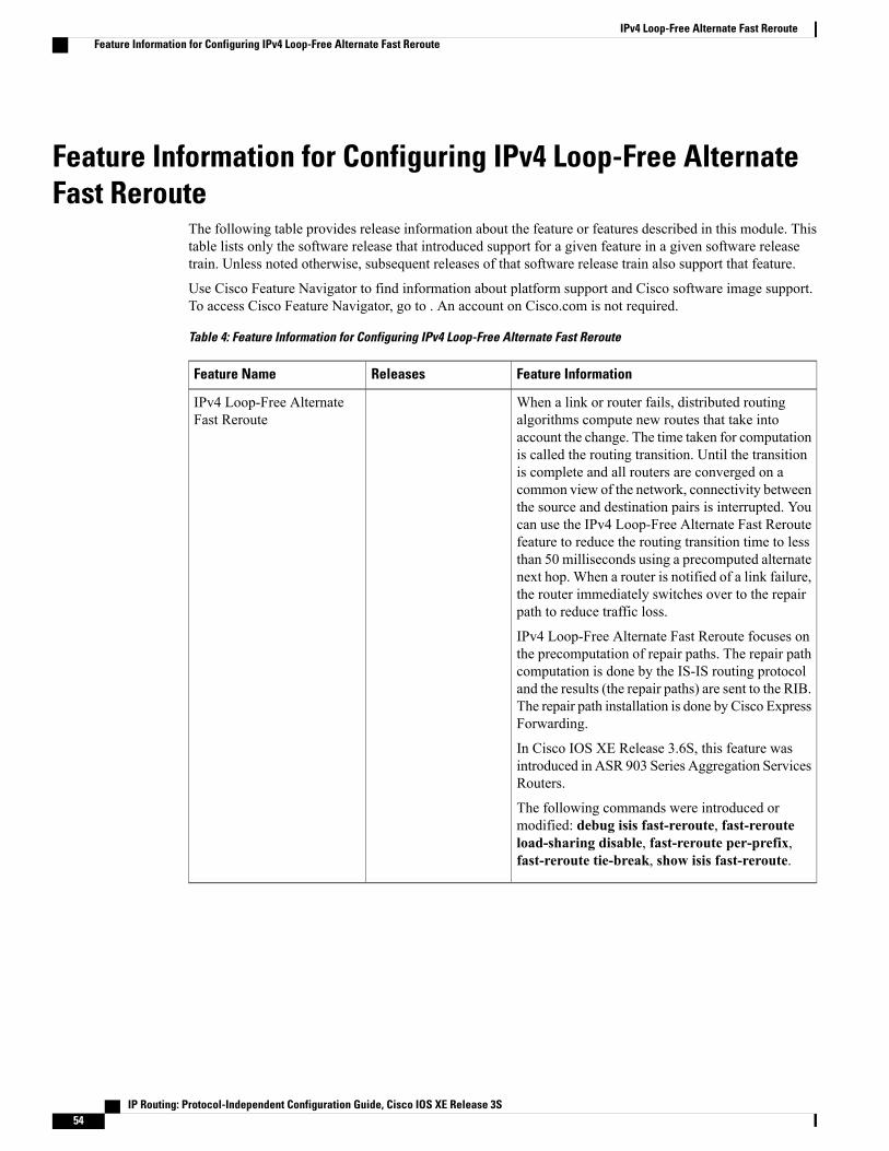
Feature Information for Configuring IPv4 Loop-Free AlternateFast Reroute
The following table provides release information about the feature or features described in this module. Thistable lists only the software release that introduced support for a given feature in a given software releasetrain. Unless noted otherwise, subsequent releases of that software release train also support that feature.
Use Cisco Feature Navigator to find information about platform support and Cisco software image support.To access Cisco Feature Navigator, go to . An account on Cisco.com is not required.
Table 4: Feature Information for Configuring IPv4 Loop-Free Alternate Fast Reroute
Feature InformationReleasesFeature Name
When a link or router fails, distributed routingalgorithms compute new routes that take intoaccount the change. The time taken for computationis called the routing transition. Until the transitionis complete and all routers are converged on acommon view of the network, connectivity betweenthe source and destination pairs is interrupted. Youcan use the IPv4 Loop-Free Alternate Fast Reroutefeature to reduce the routing transition time to lessthan 50 milliseconds using a precomputed alternatenext hop. When a router is notified of a link failure,the router immediately switches over to the repairpath to reduce traffic loss.
IPv4 Loop-Free Alternate Fast Reroute focuses onthe precomputation of repair paths. The repair pathcomputation is done by the IS-IS routing protocoland the results (the repair paths) are sent to the RIB.The repair path installation is done by Cisco ExpressForwarding.
In Cisco IOS XE Release 3.6S, this feature wasintroduced in ASR 903 Series Aggregation ServicesRouters.
The following commands were introduced ormodified: debug isis fast-reroute, fast-rerouteload-sharing disable, fast-reroute per-prefix,fast-reroute tie-break, show isis fast-reroute.
IPv4 Loop-Free AlternateFast Reroute
IP Routing: Protocol-Independent Configuration Guide, Cisco IOS XE Release 3S54
IPv4 Loop-Free Alternate Fast RerouteFeature Information for Configuring IPv4 Loop-Free Alternate Fast Reroute

C H A P T E R 4IP Event Dampening
The IP Event Dampening feature introduces a configurable exponential decay mechanism to suppress theeffects of excessive interface flapping events on routing protocols and routing tables in the network. Thisfeature allows the network operator to configure a router to automatically identify and selectively dampena local interface that is flapping.
• Finding Feature Information, page 55
• Restrictions for IP Event Dampening, page 56
• Information About IP Event Dampening, page 56
• How to Configure IP Event Dampening, page 60
• Configuration Examples for IP Event Dampening, page 62
• Additional References, page 62
• Feature Information for IP Event Dampening, page 64
• Glossary, page 65
Finding Feature InformationYour software release may not support all the features documented in this module. For the latest caveats andfeature information, see Bug Search Tool and the release notes for your platform and software release. Tofind information about the features documented in this module, and to see a list of the releases in which eachfeature is supported, see the feature information table.
Use Cisco Feature Navigator to find information about platform support and Cisco software image support.To access Cisco Feature Navigator, go to www.cisco.com/go/cfn. An account on Cisco.com is not required.
IP Routing: Protocol-Independent Configuration Guide, Cisco IOS XE Release 3S 55
Restrictions for IP Event DampeningSubinterface Restrictions
Only primary interfaces can be configured with this feature. The primary interface configuration is appliedto all subinterfaces by default. IP Event Dampening does not track the flapping of individual subinterfaceson an interface.
Virtual Templates Not Supported
Copying a dampening configuration from virtual templates to virtual access interfaces is not supported becausedampening has limited usefulness to existing applications that use virtual templates. Virtual access interfacesare released when an interface flaps, and new connections and virtual access interfaces are acquired when theinterface comes up and is made available to the network. Since dampening states are attached to the interface,the dampening states would not survive an interface flap.
IPX Routing Protocols Not Supported
Internetwork Packet Exchange (IPX) protocols are not supported by the IP Event Dampening feature. However,IPX variants of these protocols will still receive up and down state event information when this feature isenabled. This should not create any problems or routing issues.
Information About IP Event Dampening
IP Event Dampening OverviewInterface state changes occur when interfaces are administratively brought up or down or if an interfacechanges state. When an interface changes state or flaps, routing protocols are notified of the status of theroutes that are affected by the change in state. Every interface state change requires all affected devices in thenetwork to recalculate best paths, install or remove routes from the routing tables, and then advertise validroutes to peer routers. An unstable interface that flaps excessively can cause other devices in the network toconsume substantial amounts of system processing resources and cause routing protocols to lose synchronizationwith the state of the flapping interface.
The IP Event Dampening feature introduces a configurable exponential decay mechanism to suppress theeffects of excessive interface flapping events on routing protocols and routing tables in the network. Thisfeature allows the network operator to configure a router to automatically identify and selectively dampen alocal interface that is flapping. Dampening an interface removes the interface from the network until theinterface stops flapping and becomes stable. Configuring the IP Event Dampening feature improves convergencetimes and stability throughout the network by isolating failures so that disturbances are not propagated. This,in turn, reduces the utilization of system processing resources by other devices in the network and improvesoverall network stability.
Interface State Change EventsThis section describes the interface state change events of the IP Event Dampening features. This featureemploys a configurable exponential decay mechanism that is used to suppress the effects of excessive interface
IP Routing: Protocol-Independent Configuration Guide, Cisco IOS XE Release 3S56
IP Event DampeningRestrictions for IP Event Dampening

flapping or state changes.When the IP Event Dampening feature is enabled, flapping interfaces are dampenedfrom the perspective of the routing protocol by filtering excessive route updates. Flapping interfaces areidentified, assigned penalties, suppressed if the necessary, andmade available to the network when the interfacestabilizes.
Suppress ThresholdThe suppress threshold is the value of the accumulated penalty that triggers the router to dampen a flappinginterface. The flapping interface is identified by the router and assigned a penalty for each up and down statechange, but the interface is not automatically dampened. The router tracks the penalties that a flapping interfaceaccumulates. When the accumulated penalty reaches the default or preconfigured suppress threshold, theinterface is placed in a dampened state.
Half-Life PeriodThe half-life period determines how fast the accumulated penalty can decay exponentially. When an interfaceis placed in a dampened state, the router monitors the interface for additional up and down state changes. Ifthe interface continues to accumulate penalties and the interface remains in the suppress threshold range, theinterface will remain dampened. If the interface stabilizes and stops flapping, the penalty is reduced by halfafter each half-life period expires. The accumulated penalty will be reduced until the penalty drops to thereuse threshold. The configurable range of the half-life period timer is from 1 to 30 seconds. The defaulthalf-life period timer is 5 seconds.
Reuse ThresholdWhen the accumulated penalty decreases until the penalty drops to the reuse threshold, the route is unsuppressedand made available to the other devices on the network. The range of the reuse value is from 1 to 20,000penalties. The default value is 1000 penalties.
Maximum Suppress TimeThe maximum suppress time represents the maximum amount of time an interface can remain dampenedwhen a penalty is assigned to an interface. The maximum suppress time can be configured from 1 to 20,000seconds. The default of the maximum penalty timer is 20 seconds or four times the default half-life period (5seconds). The maximum value of the accumulated penalty is calculated, based on the maximum suppresstime, reuse threshold, and half-life period.
Affected ComponentsWhen an interface is not configured with dampening, or when an interface is configured with dampening butis not suppressed, the routing protocol behavior as a result of interface state transitions is not changed by theIP Event Dampening feature. However, if an interface is suppressed, the routing protocols and routing tablesare immune to any further state transitions of the interface until it is unsuppressed.
Route TypesThe following interfaces are affected by the configuration of this feature:
IP Routing: Protocol-Independent Configuration Guide, Cisco IOS XE Release 3S 57
IP Event DampeningAffected Components
• Connected routes:
• The connected routes of dampened interfaces are not installed into the routing table.
• When a dampened interface is unsuppressed, the connected routes will be installed into the routingtable if the interface is up.
• Static routes:
• Static routes assigned to a dampened interface are not installed into the routing table.
• When a dampened interface is unsuppressed, the static route will be installed into the routing tableif the interface is up.
Only the primary interface can be configured with this feature, and all subinterfaces are subject to thesame dampening configuration as the primary interface. IP Event Dampening does not track the flappingof individual subinterfaces on an interface.
Note
Supported ProtocolsThe IP Event Dampening feature supports Routing Information Protocol (RIP), Open Shortest Path First(OSPF), Enhanced Interior Gateway Routing Protocol (EIGRP), Intermediate System-to-Intermediate System(IS-IS), Border Gateway Protocol (BGP), Connectionless Network Services (CLNS), and Hot Standby RoutingProtocol (HSRP). The following list provides some general information about the operation of this featurewith these protocols.
• RIP, OSPF, EIGRP, IS-IS, and BGP:
• When an interface is dampened, the interface is considered to be down by the routing protocol.The routing protocol will not hold any adjacencies with this peer router over the dampened interfaceor generate advertisements of any routes related to this interface to other peer routers.
• When the interface is unsuppressed and made available to the network, the interface will beconsidered by the routing protocols to be up. The routing protocols will be notified that the interfaceis in an up state and routing conditions will return to normal.
• HSRP:
• When an interface is dampened, it is considered to be down by HSRP. HSRP will not generateHSRPmessages out of the dampened interface or respond to anymessage received by the dampenedinterface. When the interface is unsuppressed and made available to the network, HSRP will benotified of the up state and will return to normal operations.
• CLNS:
• When an interface is dampened, the interface is dampened to both IP and CLNS routing equally.The interface is dampened to both IP and CLNS because integrated routing protocols like IS-IS,IP, and CLNS routing are closely interconnected, so it is impossible to apply dampening separately.
IP Routing: Protocol-Independent Configuration Guide, Cisco IOS XE Release 3S58
IP Event DampeningAffected Components

The IP Event Dampening feature has no effect on any routing protocols if it is not enabled or an interfaceis not dampened.
Note
Network DeploymentsIn real network deployments, some routers may not be configured with interface dampening, and all routersmay not even support this feature. No major routing issues are expected, even if the router at the other end ofa point-to-point interface or routers of the same multicast LAN do not have interface dampening turned onor do not have this feature implemented. On the router, where the interface is dampened, routes associatedwith the interface will not be used. No packets will be sent out of this interface, and no routing protocol activitywill be initiated with routers on the other side of the interface. However, routers on the other side can stillinstall some routes, in their routing tables, that are associated with this subnet because the routers recognizethat their own interfaces are up and can start forwarding packets to the dampened interface. In such situations,the router with the dampened interface will start forwarding these packets, depending on the routes in itsrouting table.
The IP Event Dampening feature does not introduce new information into the network. In fact, the effect ofdampening is to subtract a subset of routing information from the network. Therefore, looping should notoccur as a result of dampening.
Benefits of IP Event Dampening
Reduced Processing Load
The IP Event Dampening Feature employs a configurable exponential decaymechanism to suppress the effectsof excessive interface flapping events on routing protocols. Excessive interface up and down state changesthat are received in a short period of time are not processed and do not consume system resources. Otherrouters in the network need not waste system resources because of a flapping route.
Faster Convergence
The IP Event Dampening feature improves convergence times and stability throughout the network by isolatingfailures so that disturbances are not propagated. Routers that are not experiencing link flap reach convergencesooner, because routing tables are not rebuilt each time the offending router leaves and enters the service
Improved Network Stability
The IP Event Dampening feature provides increased network stability. A router with a flapping interfaceremoves the flapping interface from the network until the interface stabilizes, so other routers simply redirecttraffic around the affected router until the interface becomes stable, which ensures that the router loses nodata packets.
IP Routing: Protocol-Independent Configuration Guide, Cisco IOS XE Release 3S 59
IP Event DampeningNetwork Deployments

How to Configure IP Event Dampening
Enabling IP Event DampeningThe dampening command is entered in interface configuration mode to enable the IP Event Dampeningfeature. If this command is applied to an interface that already has dampening configured, all dampeningstates are reset and the accumulated penalty will be set to 0. If the interface has been dampened, the accumulatedpenalty will fall into the reuse threshold range, and the dampened interface will be made available to thenetwork. The flap counts, however, are retained.
SUMMARY STEPS
1. enable2. configure terminal3. interface type number4. dampening [half-life-period reuse-threshold] [suppress-threshold max-suppress [restart-penalty]]5. end
DETAILED STEPS
PurposeCommand or Action
Enables privileged EXEC mode.enableStep 1
Example:
Router> enable
• Enter your password if prompted.
Enters global configuration mode.configure terminal
Example:
Router# configure terminal
Step 2
Enters interface configuration mode and configures the specifiedinterface.
interface type number
Example:
Router(config)# interface type number
Step 3
Enables interface dampening.dampening [half-life-period reuse-threshold][suppress-thresholdmax-suppress [restart-penalty]]
Step 4
• Entering the dampening command without any argumentsenables interface dampening with the default configurationparameters.Example:
Router(config-if)# dampening
IP Routing: Protocol-Independent Configuration Guide, Cisco IOS XE Release 3S60
IP Event DampeningHow to Configure IP Event Dampening

PurposeCommand or Action
• Whenmanually configuring the timer for the restart-penaltyargument, the values must be manually entered for allarguments.
Exits interface configuration mode and enters privileged EXECmode.
end
Example:
Router(config-if)# end
Step 5
Verifying IP Event DampeningUse the show dampening interface or show interface dampening commands to verify the configuration ofthe IP Event Dampening feature.
The clear counters command may be used to clear the flap count and reset it to zero. All other parametersand status, including dampening states and accumulated penalties, are not affected by this command.
SUMMARY STEPS
1. enable2. show dampening interface3. show interface dampening
DETAILED STEPS
PurposeCommand or Action
Enables privileged EXEC mode.enableStep 1
Example:
Router> enable
• Enter your password if prompted.
Displays dampened interfaces.show dampening interface
Example:
Router# show dampening interface
Step 2
Displays dampened interfaces on the local router.show interface dampening
Example:
Router# show interface dampening
Step 3
IP Routing: Protocol-Independent Configuration Guide, Cisco IOS XE Release 3S 61
IP Event DampeningVerifying IP Event Dampening

Configuration Examples for IP Event Dampening
Configuring IP Event Dampening ExampleThe following example configures interface dampening on Gigabit Ethernet interface 0/0/0 and sets the halflife to 30 seconds, the reuse threshold to 1500, the suppress threshold to 10000, and the maximum suppresstime to 120 seconds:
interface GigabitEthernet 0/0/0dampening 30 1500 10000 120The following example configures interface dampening on ATM interface 2/0/0 and uses the default interfacedampening values:
interface atm 2/0/0dampeningThe following example configures the router to apply a penalty of 500 on Gigabit Ethernet interface 0/0/0when the interface comes up for the first time after the router is reloaded:
interface GigabitEthernet 0/0/0dampening 5 500 1000 20 500
Verifying IP Event Dampening ExampleThe output of the show dampening interfacecommand displays a summary of interface dampening.
Router# show dampening interface3 interfaces are configured with dampening.No interface is being suppressed.Features that are using interface dampening:IP Routing
The output of the show interface dampening command displays the summary of the dampening parametersand the status of interfaces on the local router. The following is sample output from the show interfacedampening command.
Router# show interface dampeningGigabitEthernet0/0/0Flaps Penalty Supp ReuseTm HalfL ReuseV SuppV MaxSTm MaxP Restart
0 0 FALSE 0 5 1000 2000 20 16000 0ATM2/0/0Flaps Penalty Supp ReuseTm HalfL ReuseV SuppV MaxSTm MaxP Restart
0 0 FALSE 0 5 1000 2000 20 16000 0POS2/0/0Flaps Penalty Supp ReuseTm HalfL ReuseV SuppV MaxSTm MaxP Restart
0 0 FALSE 0 5 1000 2000 20 16000 0
Additional ReferencesThe following sections provide references related to the IP Event Dampening feature.
IP Routing: Protocol-Independent Configuration Guide, Cisco IOS XE Release 3S62
IP Event DampeningConfiguration Examples for IP Event Dampening

Related Documents
Document TitleRelated Topic
Cisco IOS IP Routing: Protocol-IndependentCommand Reference
IP Routing Protocol-Independent commands
Cisco IOS Master Command List, All ReleasesCisco IOS master command list, all releases
Standards
TitleStandard
--No new or modified standards are supported by thisfeature, and support for existing standards has notbeen modified by this feature.
MIBs
MIBs LinkMIB
To locate and downloadMIBs for selected platforms,Cisco IOSXE software releases, and feature sets, useCisco MIB Locator found at the following URL:
http://www.cisco.com/go/mibs
No new or modified MIBs are supported by thisfeature, and support for existing MIBs has not beenmodified by this feature.
RFCs
TitleRFC
--No new or modified RFCs are supported by thisfeature, and support for existing standards has notbeen modified by this feature.
IP Routing: Protocol-Independent Configuration Guide, Cisco IOS XE Release 3S 63
IP Event DampeningAdditional References

Technical Assistance
LinkDescription
http://www.cisco.com/techsupportThe Cisco Support website provides extensive onlineresources, including documentation and tools fortroubleshooting and resolving technical issues withCisco products and technologies.
To receive security and technical information aboutyour products, you can subscribe to various services,such as the Product Alert Tool (accessed from FieldNotices), the Cisco Technical Services Newsletter,and Really Simple Syndication (RSS) Feeds.
Access to most tools on the Cisco Support websiterequires a Cisco.com user ID and password.
Feature Information for IP Event DampeningThe following table provides release information about the feature or features described in this module. Thistable lists only the software release that introduced support for a given feature in a given software releasetrain. Unless noted otherwise, subsequent releases of that software release train also support that feature.
Use Cisco Feature Navigator to find information about platform support and Cisco software image support.To access Cisco Feature Navigator, go to . An account on Cisco.com is not required.
Table 5: Feature Information for IP Event Dampening
Feature InformationReleasesFeature Name
The IP Event Dampening featureintroduces a configurableexponential decay mechanism tosuppress the effects of excessiveinterface flapping events on routingprotocols and routing tables in thenetwork. This feature allows thenetwork operator to configure arouter to automatically identify andselectively dampen a local interfacethat is flapping.
This feature was introduced on theCisco ASR 1000 SeriesAggregation Services Routers.
The following commands wereintroduced by this feature:dampening, debug dampening,show dampening interface, showinterface dampening.
Cisco IOS XE Release 2.1IP Event Dampening
IP Routing: Protocol-Independent Configuration Guide, Cisco IOS XE Release 3S64
IP Event DampeningFeature Information for IP Event Dampening

Glossaryevent dampening --The process in which a router dampens a flapping interface from the perspective of therouting tables and routing protocols of IP by filtering the excessive route adjust message because of theinterface state change.
Flap --Rapid interface state changes from up to down and down to up within a short period of time.
half life --The rate of the exponential decay of the accumulated penalty is determined by this value.
maximum penalty --The maximum value beyond which the penalty assigned does not increase. It is derivedfrom the maximum suppress time.
maximum suppress time --The maximum amount of time the interface can stay suppressed at the time apenalty is assigned.
penalty --A value assigned to an interface when it flaps. This value increases with each flap and decreasesover time. The rate at which it decreases depends on the half life.
reuse threshold --The threshold value after which the interface will be unsuppressed and can be used again.
suppress threshold --Value of the accumulated penalty that triggers the router to dampen a flapping interface.When the accumulated penalty exceeds this value, the interface state is considered to be down from theperspective of the routing protocol.
suppressed --Suppressing an interface removes an interface from the network from the perspective of therouting protocol. An interface enters the suppressed state when it has flapped frequently enough for the penaltyassigned to it to cross a threshold limit.
IP Routing: Protocol-Independent Configuration Guide, Cisco IOS XE Release 3S 65
IP Event DampeningGlossary

IP Routing: Protocol-Independent Configuration Guide, Cisco IOS XE Release 3S66
IP Event DampeningGlossary
C H A P T E R 5PBR Recursive Next Hop
The PBR Recursive Next Hop feature enhances route maps to enable configuration of a recursive next-hopIP address that is used by policy-based routing (PBR). The recursive next-hop IP address is installed in therouting table and can be a subnet that is not directly connected. If the recursive next-hop IP address is notavailable, packets are routed using a default route.
Because Cisco Express Forwarding (CEF) or process switching provides the infrastructure, the benefit ofthis feature is the CEF loadsharing.
• Finding Feature Information, page 67
• Restrictions for PBR Recursive Next Hop, page 67
• Information About PBR Recursive Next-Hop, page 68
• How to Configure PBR Recursive Next Hop, page 68
• Configuration Examples for PBR Recursive Next Hop, page 72
• Additional References for PBR Recursive Next Hop , page 73
• Feature Information for PBR Recursive Next Hop, page 74
Finding Feature InformationYour software release may not support all the features documented in this module. For the latest caveats andfeature information, see Bug Search Tool and the release notes for your platform and software release. Tofind information about the features documented in this module, and to see a list of the releases in which eachfeature is supported, see the feature information table.
Use Cisco Feature Navigator to find information about platform support and Cisco software image support.To access Cisco Feature Navigator, go to www.cisco.com/go/cfn. An account on Cisco.com is not required.
Restrictions for PBR Recursive Next HopIf there are multiple equal-cost routes to the subnet that have been configured by the set next-hop recursivecommand, load balancing will occur only if all the adjacencies to the routes are resolved. If any of theadjacencies have not been resolved, load balancing will not occur and only one of the routes whose adjacency
IP Routing: Protocol-Independent Configuration Guide, Cisco IOS XE Release 3S 67

is resolved will be used. If none of the adjacencies are resolved, then the packets will be processed, resultingin the resolution of at least one of the adjacencies, leading to the programming of the adjacency in the hardware.Policy based routing relies on routing protocols or other means to resolve all adjacencies and as a result, loadbalancing occurs.
PBR Recursive Next Hope for IPv6 does not support load sharing.
Information About PBR Recursive Next-Hop
PBR Recursive Next Hop OverviewThe PBR Recursive Next Hop feature enhances route maps to enable configuration of a recursive next-hopIP address that is used by policy-based routing (PBR). The recursive next-hop IP address is installed in therouting table and can be a subnet that is not directly connected. If the recursive next-hop IP address is notavailable, packets are routed using a default route.
PBR Recursive Next Hop for IPv6 also supports non-directly connected next hop. The recursive next hopspecified can be a host address or a subnet address. The routing table is looked up to get the next hop basedon the longest match of addresses. Only one such recursive next hop is supported per route map entry.
How to Configure PBR Recursive Next Hop
Setting the Recursive Next-Hop IP AddressThe infrastructure provided by CEF or process switching performs the recursion to the next-hop IP address.The configuration sequence, which affects routing, is as follows:
1 Next-hop
2 Next-hop recursive
3 Interface
4 Default next-hop
5 Default interface
If both a next-hop address and a recursive next-hop IP address are present in the same route-map entry, thenext hop is used. If the next hop is not available, the recursive next hop is used. If the recursive next hop isnot available and no other IP address is present, the packet is routed using the default routing table; it is notdropped. If the packet is supposed to be dropped, use the set ip next-hopcommandwith the recursive keyword,followed by a set interface null0 configuration.
Perform this task to set the IP address for the recursive next-hop router.
Before You Begin
If loadsharing is required, CEF loadsharing should be configured for per-packet or per-destination loadsharing.Loadbalancing should be done over all equal-cost routes to the subnet that has been configured by the set ipnext-hop recursivecommand.
IP Routing: Protocol-Independent Configuration Guide, Cisco IOS XE Release 3S68
PBR Recursive Next HopInformation About PBR Recursive Next-Hop
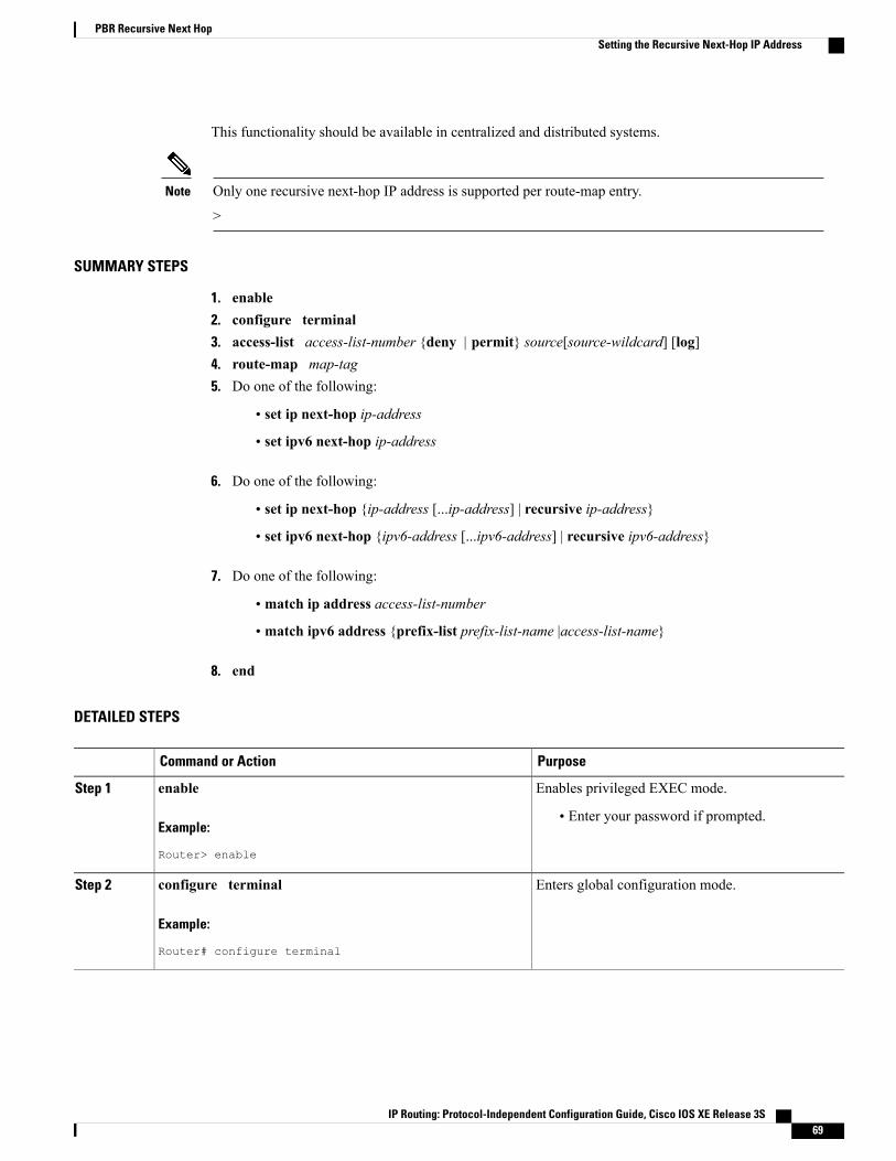
This functionality should be available in centralized and distributed systems.
Only one recursive next-hop IP address is supported per route-map entry.
>
Note
SUMMARY STEPS
1. enable2. configure terminal3. access-list access-list-number {deny | permit} source[source-wildcard] [log]4. route-map map-tag5. Do one of the following:
• set ip next-hop ip-address
• set ipv6 next-hop ip-address
6. Do one of the following:
• set ip next-hop {ip-address [...ip-address] | recursive ip-address}
• set ipv6 next-hop {ipv6-address [...ipv6-address] | recursive ipv6-address}
7. Do one of the following:
• match ip address access-list-number
• match ipv6 address {prefix-list prefix-list-name |access-list-name}
8. end
DETAILED STEPS
PurposeCommand or Action
Enables privileged EXEC mode.enableStep 1
Example:
Router> enable
• Enter your password if prompted.
Enters global configuration mode.configure terminal
Example:
Router# configure terminal
Step 2
IP Routing: Protocol-Independent Configuration Guide, Cisco IOS XE Release 3S 69
PBR Recursive Next HopSetting the Recursive Next-Hop IP Address
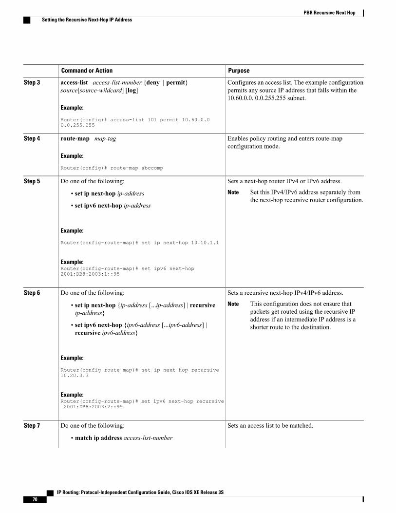
PurposeCommand or Action
Configures an access list. The example configurationpermits any source IP address that falls within the10.60.0.0. 0.0.255.255 subnet.
access-list access-list-number {deny | permit}source[source-wildcard] [log]
Example:
Router(config)# access-list 101 permit 10.60.0.00.0.255.255
Step 3
Enables policy routing and enters route-mapconfiguration mode.
route-map map-tag
Example:
Router(config)# route-map abccomp
Step 4
Sets a next-hop router IPv4 or IPv6 address.Do one of the following:Step 5
Set this IPv4/IPv6 address separately fromthe next-hop recursive router configuration.
Note• set ip next-hop ip-address
• set ipv6 next-hop ip-address
Example:
Router(config-route-map)# set ip next-hop 10.10.1.1
Example:Router(config-route-map)# set ipv6 next-hop2001:DB8:2003:1::95
Sets a recursive next-hop IPv4/IPv6 address.Do one of the following:Step 6
This configuration does not ensure thatpackets get routed using the recursive IPaddress if an intermediate IP address is ashorter route to the destination.
Note• set ip next-hop {ip-address [...ip-address] | recursiveip-address}
• set ipv6 next-hop {ipv6-address [...ipv6-address] |recursive ipv6-address}
Example:
Router(config-route-map)# set ip next-hop recursive10.20.3.3
Example:Router(config-route-map)# set ipv6 next-hop recursive2001:DB8:2003:2::95
Sets an access list to be matched.Do one of the following:Step 7
• match ip address access-list-number
IP Routing: Protocol-Independent Configuration Guide, Cisco IOS XE Release 3S70
PBR Recursive Next HopSetting the Recursive Next-Hop IP Address

PurposeCommand or Action
• match ipv6 address {prefix-list prefix-list-name|access-list-name}
Example:
Router(config-route-map)# match ip address 101
Example:Router(config-route-map)# match ipv6 address kmd
Exits route-map configuration mode and returns toprivileged EXEC mode.
end
Example:
Router(config-route-map)# end
Step 8
Verifying the Recursive Next-Hop ConfigurationTo verify the recursive next-hop configuration, perform the following steps.
SUMMARY STEPS
1. show running-config | begin abccomp2. show route-map map-name
DETAILED STEPS
Step 1 show running-config | begin abccompUse this command to verify the IPv4/IPv6 addresses for a next-hop and recursive next-hop IPv4/IPv6 address as listedin the following examples:
Example:
Router# show running-config | begin abccomproute-map abccomp permit 10match ip address 101 ! Defines the match criteria for an access list.set ip next-hop recursive 10.3.3.3 ! If the match criteria are met, the recursive IP address isset.set ip next-hop 10.1.1.1 10.2.2.2 10.4.4.4
Router# show running-config | begin abccomproute-map abccomp permit 10match ip address kmd! Defines the match criteria for an access list.set ipv6 next-hop recursive 2001:DB8:3000:1 ! If the match criteria are met, the recursive IPv6
IP Routing: Protocol-Independent Configuration Guide, Cisco IOS XE Release 3S 71
PBR Recursive Next HopVerifying the Recursive Next-Hop Configuration

address is set.set ipv6 next-hop 2001:DB8:3000:1 2001:DB8:4000:1 2001:DB8:5000:1
Step 2 show route-map map-nameUse this command to display the route maps, for example:
Example:
Router# show route-map abccomproute-map abccomp, permit, sequence 10Match clauses:ip address (access-lists): 101Set clauses:ip next-hop recursive 10.3.3.3ip next-hop 10.1.1.1 10.2.2.2 10.4.4.4Policy routing matches: 0 packets, 0 bytes
Router# show route-map abccomproute-map abccomp, permit, sequence 10Match clauses:ipv6 address (access-lists): kmdSet clauses:ipv6 next-hop recursive 2001:DB8:3000:1ipv6 next-hop 2001:DB8:3000:1 2001:DB8:4000:1 2001:DB8:5000:1Policy routing matches: 0 packets, 0 bytes
Configuration Examples for PBR Recursive Next Hop
Example: Recursive Next-Hop IP AddressThe following example shows the configuration of IP address 10.3.3.3 as the recursive next-hop router:
route-map abccompset ip next-hop 10.1.1.1set ip next-hop 10.2.2.2set ip next-hop recursive 10.3.3.3set ip next-hop 10.4.4.4The following example shows the configuration of IPv6 address 2001:DB8:2003:1::95 as the recursive next-hoprouter:
route-map abccompset ipv6 next-hop 2001:DB8:2003:1::95set ipv6 next-hop 2001:DB8:2004:3::96set ipv6 next-hop recursive 2001:DB8:2005:2::95set ipv6 next-hop 2001:DB8:2006:1::95
IP Routing: Protocol-Independent Configuration Guide, Cisco IOS XE Release 3S72
PBR Recursive Next HopConfiguration Examples for PBR Recursive Next Hop
Additional References for PBR Recursive Next HopRelated Documents
Document TitleRelated Topic
Cisco IOS Master Command List, All ReleasesCisco IOS master command list, all releases
Cisco IOS IP Routing: Protocol-IndependentCommand Reference
IP routing protocol-independent commands: completecommand syntax, command mode, defaults, usageguidelines, and examples
Basic System Management Configuration GuidePerforming basic system management
"BGP Multipath Load Sharing for Both eBGP andiBGP in an MPLS-VPN" module in the BGPConfiguration Guide
Changing the maximum number of paths
"Connecting to a Service Provider Using ExternalBGP" module in the BGP Configuration Guide
BGP route map configuration tasks and configurationexamples.
"BGP Cost Community" module in the BGPConfiguration Guide
BGP communities and route maps.
"IPv6 Policy-Based Routing " module in the IPRouting: Protocol-Independent ConfigurationGuide
IPv6 Policy-Based Routing
RFCs
TitleRFC
Internet ProtocolRFC 791
Variable-Length Subnet MasksRFC 1219
IP Routing: Protocol-Independent Configuration Guide, Cisco IOS XE Release 3S 73
PBR Recursive Next HopAdditional References for PBR Recursive Next Hop
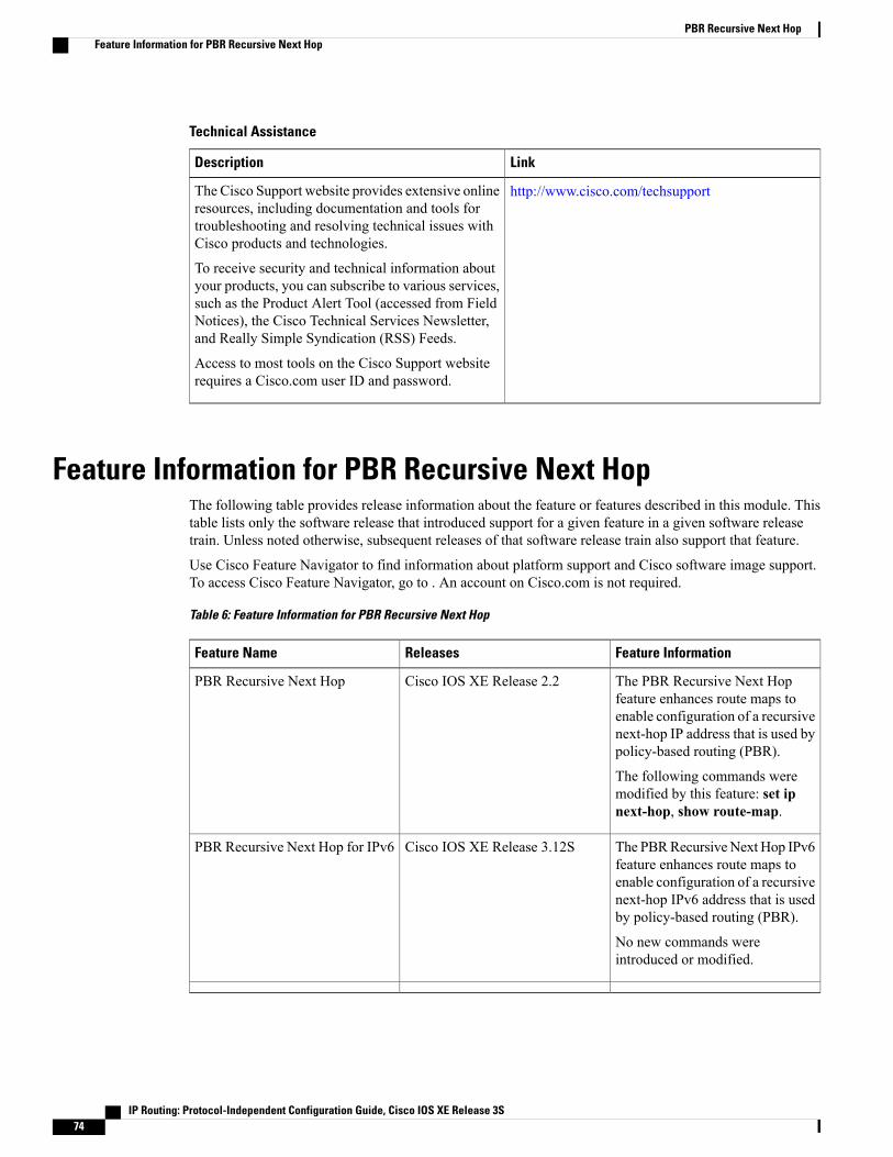
Technical Assistance
LinkDescription
http://www.cisco.com/techsupportThe Cisco Support website provides extensive onlineresources, including documentation and tools fortroubleshooting and resolving technical issues withCisco products and technologies.
To receive security and technical information aboutyour products, you can subscribe to various services,such as the Product Alert Tool (accessed from FieldNotices), the Cisco Technical Services Newsletter,and Really Simple Syndication (RSS) Feeds.
Access to most tools on the Cisco Support websiterequires a Cisco.com user ID and password.
Feature Information for PBR Recursive Next HopThe following table provides release information about the feature or features described in this module. Thistable lists only the software release that introduced support for a given feature in a given software releasetrain. Unless noted otherwise, subsequent releases of that software release train also support that feature.
Use Cisco Feature Navigator to find information about platform support and Cisco software image support.To access Cisco Feature Navigator, go to . An account on Cisco.com is not required.
Table 6: Feature Information for PBR Recursive Next Hop
Feature InformationReleasesFeature Name
The PBR Recursive Next Hopfeature enhances route maps toenable configuration of a recursivenext-hop IP address that is used bypolicy-based routing (PBR).
The following commands weremodified by this feature: set ipnext-hop, show route-map.
Cisco IOS XE Release 2.2PBR Recursive Next Hop
The PBRRecursiveNext Hop IPv6feature enhances route maps toenable configuration of a recursivenext-hop IPv6 address that is usedby policy-based routing (PBR).
No new commands wereintroduced or modified.
Cisco IOS XE Release 3.12SPBR Recursive Next Hop for IPv6
IP Routing: Protocol-Independent Configuration Guide, Cisco IOS XE Release 3S74
PBR Recursive Next HopFeature Information for PBR Recursive Next Hop
C H A P T E R 6PBR Support for Multiple Tracking Options
The PBR Support for Multiple Tracking Options feature extends the capabilities of object tracking usingCisco Discovery Protocol (CDP) to allow the policy-based routing (PBR) process to verify object availabilityby using additional methods. The verification method can be an Internet Control Message Protocol (ICMP)ping, a User Datagram Protocol (UDP) ping, or an HTTP GET request.
• Finding Feature Information, page 75
• Information About PBR Support for Multiple Tracking Options, page 75
• How to Configure PBR Support for Multiple Tracking Options, page 76
• Configuration Examples for PBR Support for Multiple Tracking Options, page 83
• Additional References, page 85
• Command Reference, page 85
• Feature Information for PBR Support for Multiple Tracking Options, page 86
Finding Feature InformationYour software release may not support all the features documented in this module. For the latest caveats andfeature information, see Bug Search Tool and the release notes for your platform and software release. Tofind information about the features documented in this module, and to see a list of the releases in which eachfeature is supported, see the feature information table.
Use Cisco Feature Navigator to find information about platform support and Cisco software image support.To access Cisco Feature Navigator, go to www.cisco.com/go/cfn. An account on Cisco.com is not required.
Information About PBR Support for Multiple Tracking Options
Object TrackingObject tracking is an independent process that monitors objects such as the following:
IP Routing: Protocol-Independent Configuration Guide, Cisco IOS XE Release 3S 75
• State of the line protocol of an interface
• Existence of an entry in the routing table
• Results of a Service Assurance Agent (SAA) operation, such as a ping
Clients such as Hot Standby Router Protocol (HSRP), Virtual Router Redundancy Protocol (VRRP), GatewayLoad Balancing Protocol (GLBP), and (with this feature) PBR can register their interest in specific, trackedobjects and then take action when the state of the objects changes.
PBR Support for Multiple Tracking Options Feature DesignThe PBR Support for Multiple Tracking Options feature gives PBR access to all the objects that are availablethrough the tracking process. The tracking process provides the ability to track individual objects--such asICMP ping reachability, routing adjacency, an application running on a remote device, a route in the RoutingInformation Base (RIB)--or to track the state of an interface line protocol.
Object tracking functions in the following manner. PBR will inform the tracking process that a certain objectshould be tracked. The tracking process will in turn notify PBR when the state of that object changes.
How to Configure PBR Support for Multiple Tracking OptionsThe tasks in this section are divided according to the Cisco IOS release that you are running because CiscoIOS Release 12.3(14)T introduced new syntax for IP Service Level Agreements (SLAs). To use this feature,you must be running Cisco IOS Release 12.3(4)T, 12.2(25)S, or a later release. This section contains thefollowing tasks:
Cisco IOS Release 12.3(11)T 12.2(25)S and EarlierPerform this task to configure PBR support for multiple tracking options. In this task, a route map is createdand configured to verify the reachability of the tracked object.
Before You Begin
This task requires the networking device to be running Cisco IOS Release 12.3(11)T, 12.2(25)S, or priorreleases.
IP Routing: Protocol-Independent Configuration Guide, Cisco IOS XE Release 3S76
PBR Support for Multiple Tracking OptionsPBR Support for Multiple Tracking Options Feature Design
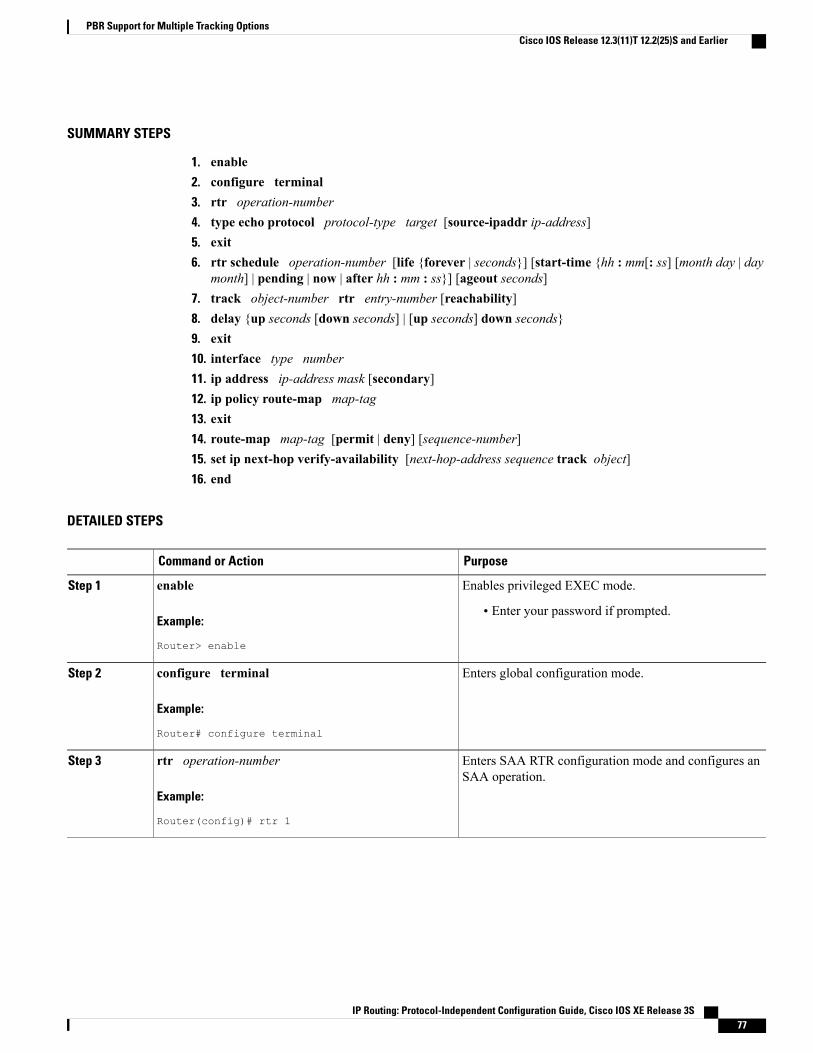
SUMMARY STEPS
1. enable2. configure terminal3. rtr operation-number4. type echo protocol protocol-type target [source-ipaddr ip-address]5. exit6. rtr schedule operation-number [life {forever | seconds}] [start-time {hh : mm[: ss] [month day | day
month] | pending | now | after hh : mm : ss}] [ageout seconds]7. track object-number rtr entry-number [reachability]8. delay {up seconds [down seconds] | [up seconds] down seconds}9. exit10. interface type number11. ip address ip-address mask [secondary]12. ip policy route-map map-tag13. exit14. route-map map-tag [permit | deny] [sequence-number]15. set ip next-hop verify-availability [next-hop-address sequence track object]16. end
DETAILED STEPS
PurposeCommand or Action
Enables privileged EXEC mode.enableStep 1
Example:
Router> enable
• Enter your password if prompted.
Enters global configuration mode.configure terminal
Example:
Router# configure terminal
Step 2
Enters SAA RTR configuration mode and configures anSAA operation.
rtr operation-number
Example:
Router(config)# rtr 1
Step 3
IP Routing: Protocol-Independent Configuration Guide, Cisco IOS XE Release 3S 77
PBR Support for Multiple Tracking OptionsCisco IOS Release 12.3(11)T 12.2(25)S and Earlier

PurposeCommand or Action
Configures an SAA end-to-end echo response time probeoperation.
type echo protocol protocol-type target[source-ipaddr ip-address]
Example:
Router(config-rtr)# type echo protocol ipicmpecho10.1.1.10
Step 4
Exits SAARTR configuration mode and returns the routerto global configuration mode.
exit
Example:
Router(config-rtr)# exit
Step 5
Configures the time parameters for the SAA operation.rtr schedule operation-number [life {forever |seconds}] [start-time {hh : mm[: ss] [month day | day
Step 6
month] | pending | now | after hh : mm : ss}] [ageoutseconds]
Example:
Router(config)# rtr schedule 1 life foreverstart-time now
Tracks the reachability of a Response Time Reporter(RTR) object and enters tracking configuration mode.
track object-number rtr entry-number [reachability]
Example:
Router(config)# track 123 rtr 1 reachability
Step 7
(Optional) Specifies a period of time (in seconds) to delaycommunicating state changes of a tracked object.
delay {up seconds [down seconds] | [up seconds] downseconds}
Example:
Router(config-track)# delay up 60 down 30
Step 8
Exits tracking configuration mode and returns the routerto global configuration mode.
exit
Example:
Router(config-track)# exit
Step 9
Specifies an interface type and number and enters interfaceconfiguration mode.
interface type number
Example:
Router(config)# interface ethernet 0
Step 10
IP Routing: Protocol-Independent Configuration Guide, Cisco IOS XE Release 3S78
PBR Support for Multiple Tracking OptionsCisco IOS Release 12.3(11)T 12.2(25)S and Earlier

PurposeCommand or Action
Specifies a primary or secondary IP address for aninterface.
ip address ip-address mask [secondary]
Example:
Router(config-if)# ip address 10.1.1.11 255.0.0.0
Step 11
• See the "Configuring IPv4 Addresses" chapter of theCisco IOS IP Addressing Services ConfigurationGuide for information on configuring IPv4 addresses.
Enables policy routing and identifies a route map to beused for policy routing.
ip policy route-map map-tag
Example:
Router(config-if)# ip policy route-map alpha
Step 12
Exits interface configuration mode and returns the routerto global configuration mode.
exit
Example:
Router(config-if)# exit
Step 13
Specifies a route map and enters route-map configurationmode.
route-map map-tag [permit | deny] [sequence-number]
Example:
Router(config)# route-map alpha
Step 14
Configures the route map to verify the reachability of thetracked object.
set ip next-hop verify-availability [next-hop-addresssequence track object]
Example:
Router(config-route-map)# set ip next-hopverify-availability 10.1.1.1 10 track 123
Step 15
Exits route-map configuration mode and returns the routerto privileged EXEC mode.
end
Example:
Router(config-route-map)# end
Step 16
Configuring PBR Support for Multiple Tracking OptionsPerform this task to configure PBR support for multiple tracking options. In this task, a route map is createdand configured to verify the reachability of the tracked object.
IP Routing: Protocol-Independent Configuration Guide, Cisco IOS XE Release 3S 79
PBR Support for Multiple Tracking OptionsConfiguring PBR Support for Multiple Tracking Options
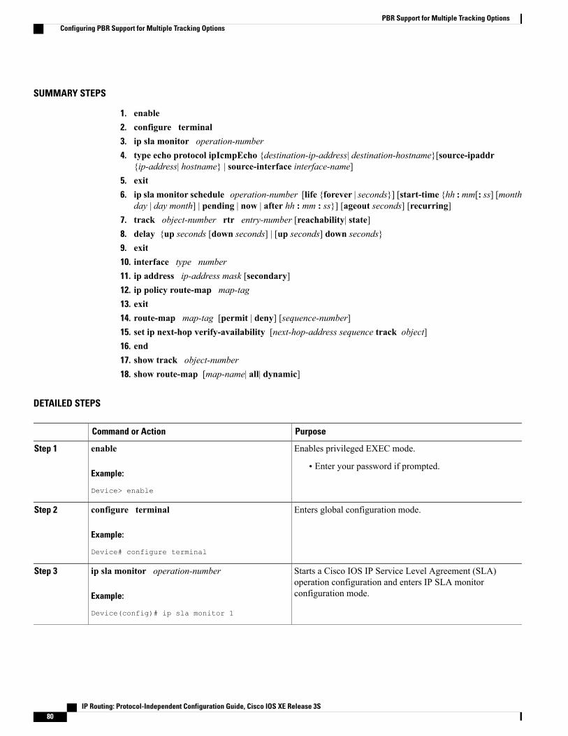
SUMMARY STEPS
1. enable2. configure terminal3. ip sla monitor operation-number4. type echo protocol ipIcmpEcho {destination-ip-address| destination-hostname}[source-ipaddr
{ip-address| hostname} | source-interface interface-name]5. exit6. ip sla monitor schedule operation-number [life {forever | seconds}] [start-time {hh :mm[: ss] [month
day | day month] | pending | now | after hh : mm : ss}] [ageout seconds] [recurring]7. track object-number rtr entry-number [reachability| state]8. delay {up seconds [down seconds] | [up seconds] down seconds}9. exit10. interface type number11. ip address ip-address mask [secondary]12. ip policy route-map map-tag13. exit14. route-map map-tag [permit | deny] [sequence-number]15. set ip next-hop verify-availability [next-hop-address sequence track object]16. end17. show track object-number18. show route-map [map-name| all| dynamic]
DETAILED STEPS
PurposeCommand or Action
Enables privileged EXEC mode.enableStep 1
Example:
Device> enable
• Enter your password if prompted.
Enters global configuration mode.configure terminal
Example:
Device# configure terminal
Step 2
Starts a Cisco IOS IP Service Level Agreement (SLA)operation configuration and enters IP SLA monitorconfiguration mode.
ip sla monitor operation-number
Example:
Device(config)# ip sla monitor 1
Step 3
IP Routing: Protocol-Independent Configuration Guide, Cisco IOS XE Release 3S80
PBR Support for Multiple Tracking OptionsConfiguring PBR Support for Multiple Tracking Options
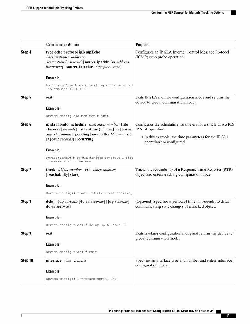
PurposeCommand or Action
Configures an IP SLA Internet Control Message Protocol(ICMP) echo probe operation.
type echo protocol ipIcmpEcho{destination-ip-address|destination-hostname}[source-ipaddr {ip-address|hostname} | source-interface interface-name]
Step 4
Example:
Device(config-sla-monitor)# type echo protocolipIcmpEcho 10.1.1.1
Exits IP SLA monitor configuration mode and returns thedevice to global configuration mode.
exit
Example:
Device(config-sla-monitor)# exit
Step 5
Configures the scheduling parameters for a single Cisco IOSIP SLA operation.
ip sla monitor schedule operation-number [life{forever | seconds}] [start-time {hh :mm[: ss] [month
Step 6
day | day month] | pending | now | after hh :mm : ss}][ageout seconds] [recurring] • In this example, the time parameters for the IP SLA
operation are configured.
Example:
Device(config)# ip sla monitor schedule 1 lifeforever start-time now
Tracks the reachability of a Response Time Reporter (RTR)object and enters tracking configuration mode.
track object-number rtr entry-number[reachability| state]
Example:
Device(config)# track 123 rtr 1 reachability
Step 7
(Optional) Specifies a period of time, in seconds, to delaycommunicating state changes of a tracked object.
delay {up seconds [down seconds] | [up seconds]down seconds}
Example:
Device(config-track)# delay up 60 down 30
Step 8
Exits tracking configuration mode and returns the device toglobal configuration mode.
exit
Example:
Device(config-track)# exit
Step 9
Specifies an interface type and number and enters interfaceconfiguration mode.
interface type number
Example:
Device(config)# interface serial 2/0
Step 10
IP Routing: Protocol-Independent Configuration Guide, Cisco IOS XE Release 3S 81
PBR Support for Multiple Tracking OptionsConfiguring PBR Support for Multiple Tracking Options

PurposeCommand or Action
Specifies a primary or secondary IP address for an interface.ip address ip-address mask [secondary]Step 11
Example:
Device(config-if)# ip address 192.168.1.1255.255.255.0
• See the "Configuring IPv4 Addresses" chapter of theCisco IOS IP Addressing Services Configuration Guidefor information on configuring IPv4 addresses.
• In this example, the IP address of the incoming interfaceis specified. This is the interface on which policy routingis to be enabled.
Enables policy routing and identifies a route map to be usedfor policy routing.
ip policy route-map map-tag
Example:
Device(config-if)# ip policy route-map alpha
Step 12
Exits interface configuration mode and returns the device toglobal configuration mode.
exit
Example:
Device(config-if)# exit
Step 13
Specifies a route map and enters route-map configurationmode.
route-map map-tag [permit | deny][sequence-number]
Example:
Device(config)# route-map alpha
Step 14
Configures the route map to verify the reachability of thetracked object.
set ip next-hop verify-availability [next-hop-addresssequence track object]
Step 15
Example:
Device(config-route-map)# set ip next-hopverify-availability 10.1.1.1 10 track 123
• In this example, the policy is configured to forwardpackets received on serial interface 2/0 to 10.1.1.1 if thatdevice is reachable.
Exits route-map configuration mode and returns the device toprivileged EXEC mode.
end
Example:
Device(config-route-map)# end
Step 16
(Optional) Displays tracking information.show track object-numberStep 17
Example:
Device# show track 123
• Use this command to verify the configuration. See thedisplay output in the "Examples" section of this task.
(Optional) Displays route map information.show route-map [map-name| all| dynamic]Step 18
IP Routing: Protocol-Independent Configuration Guide, Cisco IOS XE Release 3S82
PBR Support for Multiple Tracking OptionsConfiguring PBR Support for Multiple Tracking Options
PurposeCommand or Action
Example:
Device# show route-map alpha
• In this example, information about the route map namedalpha is displayed. See the display output in the"Examples" section of this task.
Examples
The following output from the show track command shows that the tracked object 123 is reachable.
Device# show track 123Track 123Response Time Reporter 1 reachabilityReachability is Up2 changes, last change 00:00:33
Delay up 60 secs, down 30 secsLatest operation return code: OKLatest RTT (millisecs) 20Tracked by:ROUTE-MAP 0
The following output from the show route-map command shows information about the route map namedalpha that was configured in the task.
Device# show route-map alpharoute-map alpha, permit, sequence 10Match clauses:Set clauses:ip next-hop verify-availability 10.1.1.1 10 track 123 [up]
Policy routing matches: 0 packets, 0 bytes
Configuration Examples for PBR Support for Multiple TrackingOptions
Cisco IOS Release 12.3(11)T 12.2(25)S and EarlierIn the following example, object tracking is configured for PBR on routers that are running Cisco IOS Release12.3(11)T, 12.2(25)S, or earlier releases.
The configured policy is that packets received on Ethernet interface 0, should be forwarded to 10.1.1.1 onlyif that device is reachable (responding to pings). If 10.1.1.1 is not up, then the packets should be forwardedto 10.2.2.2. If 10.2.2.2 is also not reachable, then the policy routing fails and the packets are routed accordingto the routing table.
Two Response Time Reporters (RTRs) are configured to ping the remote devices. The RTRs are then tracked.Policy routing will monitor the state of the tracked RTRs and make forwarding decisions based on their state.
! Define and start the RTRs.rtr 1type echo protocol ipicmpecho 10.1.1.1rtr schedule 1 start-time now life forever
IP Routing: Protocol-Independent Configuration Guide, Cisco IOS XE Release 3S 83
PBR Support for Multiple Tracking OptionsConfiguration Examples for PBR Support for Multiple Tracking Options

!rtr 2type echo protocol ipicmpecho 10.2.2.2rtr schedule 2 start-time now life forever!! Track the RTRs.track 123 rtr 1 reachabilitytrack 124 rtr 2 reachability!! Enable policy routing on the incoming interface.interface ethernet 0ip address 10.4.4.4 255.255.255.0ip policy route-map beta!! 10.1.1.1 is via this interface.interface ethernet 1ip address 10.1.1.254 255.255.255.0!! 10.2.2.2 is via this interface.interface ethernet 2ip address 10.2.2.254 255.255.255.0!! Define a route map to set the next-hop depending on the state of the tracked RTRs.route-map betaset ip next-hop verify-availability 10.1.1.1 10 track 123set ip next-hop verify-availability 10.2.2.2 20 track 124
Example: Configuring PBR Support for Multiple Tracking OptionsThe following example shows how to configure PBR support for multiple tracking options.
The configured policy is that packets received on Ethernet interface 0, should be forwarded to 10.1.1.1 onlyif that device is reachable (responding to pings). If 10.1.1.1 is not up, then the packets should be forwardedto 10.2.2.2. If 10.2.2.2 is also not reachable, then the policy routing fails and the packets are routed accordingto the routing table.
Two RTRs are configured to ping the remote devices. The RTRs are then tracked. Policy routing will monitorthe state of the tracked RTRs and make forwarding decisions based on their state.
! Define and start the RTRs.ip sla monitor 1type echo protocol ipicmpecho 10.1.1.1ip sla monitor schedule 1 start-time now life forever!ip sla monitor 2type echo protocol ipicmpecho 10.2.2.2ip sla monitor schedule 2 start-time now life forever!! Track the RTRs.track 123 rtr 1 reachabilitytrack 124 rtr 2 reachability!! Enable policy routing on the incoming interface.interface ethernet 0ip address 10.4.4.4 255.255.255.0ip policy route-map beta!! 10.1.1.1 is via this interface.interface ethernet 1ip address 10.1.1.254 255.255.255.0!! 10.2.2.2 is via this interface.interface ethernet 2ip address 10.2.2.254 255.255.255.0!! Define a route map to set the next-hop depending on the state of the tracked RTRs.route-map beta
IP Routing: Protocol-Independent Configuration Guide, Cisco IOS XE Release 3S84
PBR Support for Multiple Tracking OptionsExample: Configuring PBR Support for Multiple Tracking Options
set ip next-hop verify-availability 10.1.1.1 10 track 123set ip next-hop verify-availability 10.2.2.2 20 track 124
Additional ReferencesThe following sections provide references related to the PBR Support for Multiple Tracking Options feature.
Related Documents
Document TitleRelated Topic
Cisco IOS Master Command List, All ReleasesCisco IOS commands
Configuring Enhanced Object Tracking" chapter ofthe Cisco IOS IP Application Services ConfigurationGuide
Object tracking within Cisco IOS software
"Configuring IPv4 Addresses" chapter of the CiscoIOS IP Addressing Services Configuration Guide
Configuring IP addresses
Technical Assistance
LinkDescription
http://www.cisco.com/techsupportThe Cisco Support website provides extensive onlineresources, including documentation and tools fortroubleshooting and resolving technical issues withCisco products and technologies.
To receive security and technical information aboutyour products, you can subscribe to various services,such as the Product Alert Tool (accessed from FieldNotices), the Cisco Technical Services Newsletter,and Really Simple Syndication (RSS) Feeds.
Access to most tools on the Cisco Support websiterequires a Cisco.com user ID and password.
Command ReferenceThe following commands are introduced or modified in the feature or features documented in this module.For information about these commands, see the Cisco IOS IP Routing: Protocol-Independent CommandReference. For information about all Cisco IOS commands, use the Command Lookup Tool at http://tools.cisco.com/Support/CLILookup or the Cisco IOS Master Command List, All Releases , at http://www.cisco.com/en/US/docs/ios/mcl/allreleasemcl/all_book.html.
• set ip next-hop verify-availability
IP Routing: Protocol-Independent Configuration Guide, Cisco IOS XE Release 3S 85
PBR Support for Multiple Tracking OptionsAdditional References

Feature Information for PBR Support for Multiple TrackingOptions
The following table provides release information about the feature or features described in this module. Thistable lists only the software release that introduced support for a given feature in a given software releasetrain. Unless noted otherwise, subsequent releases of that software release train also support that feature.
Use Cisco Feature Navigator to find information about platform support and Cisco software image support.To access Cisco Feature Navigator, go to . An account on Cisco.com is not required.
Table 7: Feature Information for PBR Support for Multiple Tracking Options
Feature InformationReleasesFeature Name
The PBR Support for MultipleTracking Options feature extendsthe capabilities of object trackingusing Cisco Discovery Protocol(CDP) to allow the policy-basedrouting (PBR) process to verifyobject availability by usingadditional methods. Theverification method can be anInternet Control Message Protocol(ICMP) ping, a User DatagramProtocol (UDP) ping, or an HTTPGET request.
The following commands wereintroduced or modified by thisfeature: set ip next-hopverify-availability.
PBRSupport forMultiple TrackingOptions
IP Routing: Protocol-Independent Configuration Guide, Cisco IOS XE Release 3S86
PBR Support for Multiple Tracking OptionsFeature Information for PBR Support for Multiple Tracking Options
C H A P T E R 7PBR Match Track Object
The PBR Match Track Object feature enables a device to track the stub object during Policy Based Routing(PBR).
• Finding Feature Information, page 87
• Restrictions for PBR Match Track Object, page 87
• Information About PBR Match Track Object, page 88
• How to Configure PBR Match Track Object, page 89
• Verifying PBR Match Track Object, page 90
• Configuration Examples for PBR Match Track Object, page 90
• Additional References for PBR Match Track Object, page 91
• Feature Information for PBR Match Track Object, page 91
Finding Feature InformationYour software release may not support all the features documented in this module. For the latest caveats andfeature information, see Bug Search Tool and the release notes for your platform and software release. Tofind information about the features documented in this module, and to see a list of the releases in which eachfeature is supported, see the feature information table.
Use Cisco Feature Navigator to find information about platform support and Cisco software image support.To access Cisco Feature Navigator, go to www.cisco.com/go/cfn. An account on Cisco.com is not required.
Restrictions for PBR Match Track Object• You can use only one match track variable at a time in a route map sequence.
• You must remove the existing match track object configuration before configuring another match trackobject. The match track object is unregistered from the tracking component when you remove the matchtrack object number configuration.
IP Routing: Protocol-Independent Configuration Guide, Cisco IOS XE Release 3S 87
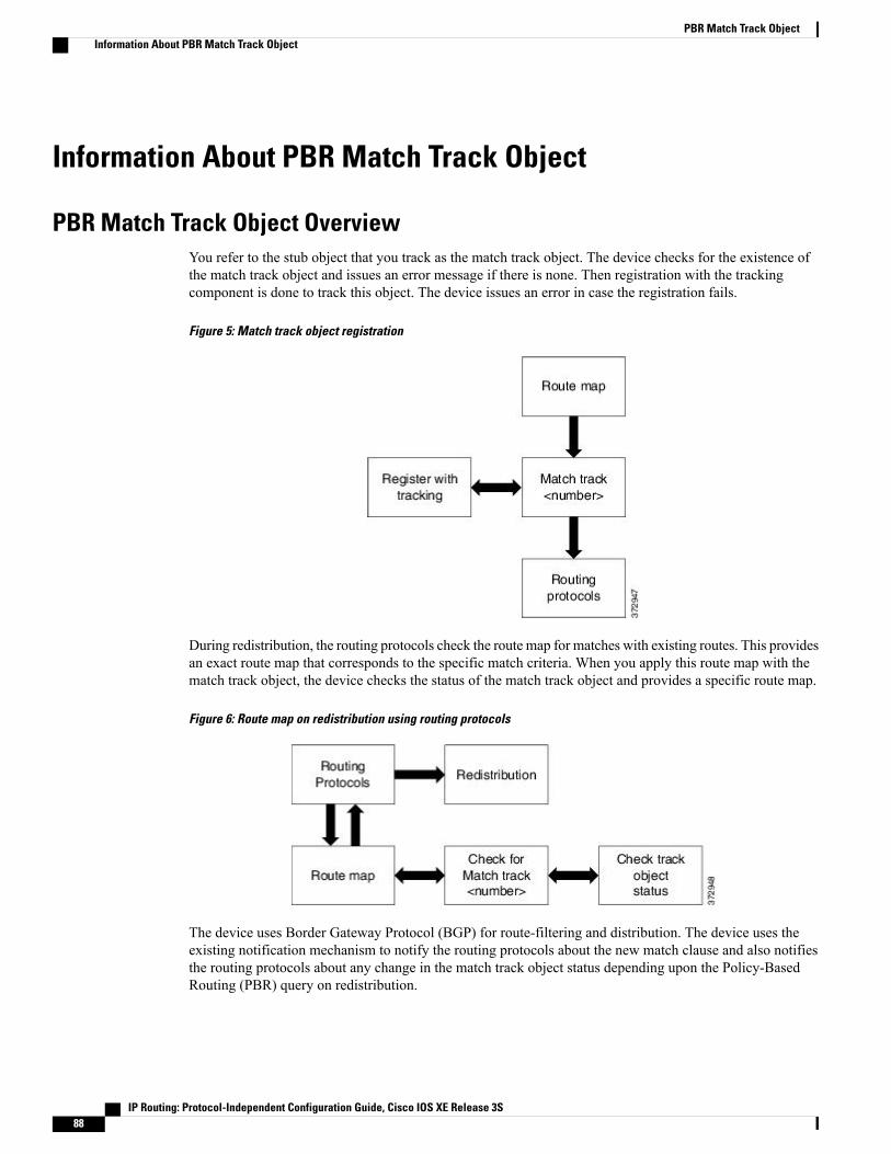
Information About PBR Match Track Object
PBR Match Track Object OverviewYou refer to the stub object that you track as the match track object. The device checks for the existence ofthe match track object and issues an error message if there is none. Then registration with the trackingcomponent is done to track this object. The device issues an error in case the registration fails.
Figure 5: Match track object registration
During redistribution, the routing protocols check the route map for matches with existing routes. This providesan exact route map that corresponds to the specific match criteria. When you apply this route map with thematch track object, the device checks the status of the match track object and provides a specific route map.
Figure 6: Route map on redistribution using routing protocols
The device uses Border Gateway Protocol (BGP) for route-filtering and distribution. The device uses theexisting notification mechanism to notify the routing protocols about the new match clause and also notifiesthe routing protocols about any change in the match track object status depending upon the Policy-BasedRouting (PBR) query on redistribution.
IP Routing: Protocol-Independent Configuration Guide, Cisco IOS XE Release 3S88
PBR Match Track ObjectInformation About PBR Match Track Object
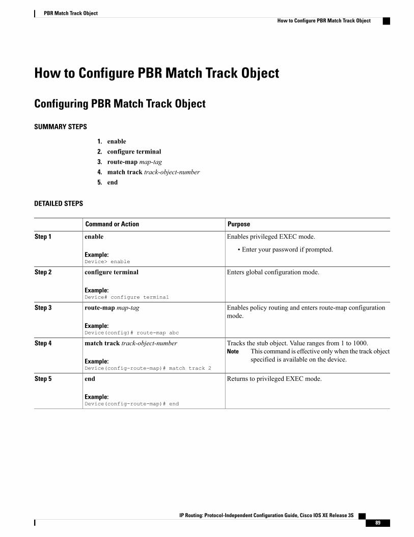
How to Configure PBR Match Track Object
Configuring PBR Match Track Object
SUMMARY STEPS
1. enable2. configure terminal3. route-map map-tag4. match track track-object-number5. end
DETAILED STEPS
PurposeCommand or Action
Enables privileged EXEC mode.enable
Example:Device> enable
Step 1
• Enter your password if prompted.
Enters global configuration mode.configure terminal
Example:Device# configure terminal
Step 2
Enables policy routing and enters route-map configurationmode.
route-map map-tag
Example:Device(config)# route-map abc
Step 3
Tracks the stub object. Value ranges from 1 to 1000.This command is effective only when the track objectspecified is available on the device.
Notematch track track-object-number
Example:Device(config-route-map)# match track 2
Step 4
Returns to privileged EXEC mode.end
Example:Device(config-route-map)# end
Step 5
IP Routing: Protocol-Independent Configuration Guide, Cisco IOS XE Release 3S 89
PBR Match Track ObjectHow to Configure PBR Match Track Object
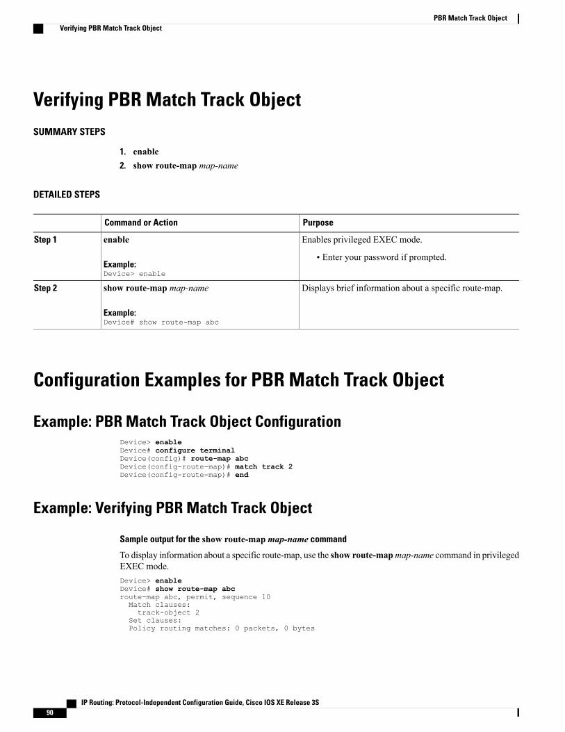
Verifying PBR Match Track ObjectSUMMARY STEPS
1. enable2. show route-map map-name
DETAILED STEPS
PurposeCommand or Action
Enables privileged EXEC mode.enable
Example:Device> enable
Step 1
• Enter your password if prompted.
Displays brief information about a specific route-map.show route-map map-name
Example:Device# show route-map abc
Step 2
Configuration Examples for PBR Match Track Object
Example: PBR Match Track Object ConfigurationDevice> enableDevice# configure terminalDevice(config)# route-map abcDevice(config-route-map)# match track 2Device(config-route-map)# end
Example: Verifying PBR Match Track Object
Sample output for the show route-mapmap-name command
To display information about a specific route-map, use the show route-mapmap-name command in privilegedEXEC mode.Device> enableDevice# show route-map abcroute-map abc, permit, sequence 10Match clauses:track-object 2
Set clauses:Policy routing matches: 0 packets, 0 bytes
IP Routing: Protocol-Independent Configuration Guide, Cisco IOS XE Release 3S90
PBR Match Track ObjectVerifying PBR Match Track Object
Additional References for PBR Match Track ObjectRelated Documents
Document TitleRelated Topic
Cisco IOS Master Command List, All ReleasesCisco IOS commands
Technical Assistance
LinkDescription
http://www.cisco.com/supportThe Cisco Support website provides extensive onlineresources, including documentation and tools fortroubleshooting and resolving technical issues withCisco products and technologies.
To receive security and technical information aboutyour products, you can subscribe to various services,such as the Product Alert Tool (accessed from FieldNotices), the Cisco Technical Services Newsletter,and Really Simple Syndication (RSS) Feeds.
Access to most tools on the Cisco Support websiterequires a Cisco.com user ID and password.
Feature Information for PBR Match Track ObjectThe following table provides release information about the feature or features described in this module. Thistable lists only the software release that introduced support for a given feature in a given software releasetrain. Unless noted otherwise, subsequent releases of that software release train also support that feature.
Use Cisco Feature Navigator to find information about platform support and Cisco software image support.To access Cisco Feature Navigator, go to . An account on Cisco.com is not required.
Feature InformationReleasesFeature Name
The PBR Match Track Objectfeature enables a device to trackthe stub object during Policy BasedRouting.
The following command wasintroduced:match tracktrack-object-number
Cisco IOS XE Release 3.13SPBR Match Track Object
IP Routing: Protocol-Independent Configuration Guide, Cisco IOS XE Release 3S 91
PBR Match Track ObjectAdditional References for PBR Match Track Object

IP Routing: Protocol-Independent Configuration Guide, Cisco IOS XE Release 3S92
PBR Match Track ObjectFeature Information for PBR Match Track Object
C H A P T E R 8IPv6 Policy-Based Routing
Policy-based routing (PBR) in both IPv6 and IPv4 allows a user to manually configure how received packetsshould be routed. PBR allows the user to identify packets by using several attributes and to specify the nexthop or the output interface to which the packet should be sent. PBR also provides a basic packet-markingcapability.
• Finding Feature Information, page 93
• Information About IPv6 Policy-Based Routing, page 93
• How to Enable IPv6 Policy-Based Routing, page 96
• Configuration Examples for IPv6 Policy-Based Routing, page 102
• Additional References for IPv6 Policy-Based Routing, page 103
• Feature Information for IPv6 Policy-Based Routing, page 103
Finding Feature InformationYour software release may not support all the features documented in this module. For the latest caveats andfeature information, see Bug Search Tool and the release notes for your platform and software release. Tofind information about the features documented in this module, and to see a list of the releases in which eachfeature is supported, see the feature information table.
Use Cisco Feature Navigator to find information about platform support and Cisco software image support.To access Cisco Feature Navigator, go to www.cisco.com/go/cfn. An account on Cisco.com is not required.
Information About IPv6 Policy-Based Routing
Policy-Based Routing OverviewPolicy-based routing (PBR) gives you a flexible means of routing packets by allowing you to configure adefined policy for traffic flows, which lessens reliance on routes derived from routing protocols. Therefore,PBR gives you more control over routing by extending and complementing the existing mechanisms provided
IP Routing: Protocol-Independent Configuration Guide, Cisco IOS XE Release 3S 93
by routing protocols. PBR allows you to set the IPv6 precedence. For a simple policy, you can use any oneof these tasks; for a complex policy, you can use all of them. It also allows you to specify a path for certaintraffic, such as priority traffic over a high-cost link.
PBR for IPv6 may be applied to both forwarded and originated IPv6 packets. For forwarded packets, PBRfor IPv6 will be implemented as an IPv6 input interface feature, supported in the following forwarding paths:
• Process
• Cisco Express Forwarding (formerly known as CEF)
• Distributed Cisco Express Forwarding
Policies can be based on the IPv6 address, port numbers, protocols, or packet size.
PBR allows you to perform the following tasks:
• Classify traffic based on extended access list criteria. Access lists, then, establish the match criteria.
• Set IPv6 precedence bits, giving the network the ability to enable differentiated classes of service.
• Route packets to specific traffic-engineered paths; you might need to route them to allow a specificquality of service (QoS) through the network.
PBR allows you to classify and mark packets at the edge of the network. PBR marks a packet by settingprecedence value. The precedence value can be used directly by devices in the network core to apply theappropriate QoS to a packet, which keeps packet classification at your network edge.
How Policy-Based Routing WorksAll packets received on an interface with policy-based routing (PBR) enabled are passed through enhancedpacket filters called route maps. The route maps used by PBR dictate the policy, determining where to forwardpackets.
Route maps are composed of statements. The route map statements can be marked as permit or deny, and theyare interpreted in the following ways:
• If a packet matches all match statements for a route map that is marked as permit, the device attemptsto policy route the packet using the set statements. Otherwise, the packet is forwarded normally.
• If the packet matches any match statements for a route map that is marked as deny, the packet is notsubject to PBR and is forwarded normally.
• If the statement is marked as permit and the packets do not match any route map statements, the packetsare sent back through normal forwarding channels and destination-based routing is performed.
You must configure policy-based routing (PBR) on the interface that receives the packet, and not on theinterface from which the packet is sent.
Packet MatchingPolicy-based routing (PBR) for IPv6 will match packets using thematch ipv6 address command in theassociated PBR route map. Packet match criteria are those criteria supported by IPv6 access lists, as follows:
• Input interface
IP Routing: Protocol-Independent Configuration Guide, Cisco IOS XE Release 3S94
IPv6 Policy-Based RoutingHow Policy-Based Routing Works

• Source IPv6 address (standard or extended access control list [ACL])
• Destination IPv6 address (standard or extended ACL)
• Protocol (extended ACL)
• Source port and destination port (extended ACL)
• DSCP (extended ACL)
• Flow-label (extended ACL)
• Fragment (extended ACL)
Packets may also be matched by length using thematch length command in the PBR route map.
Match statements are evaluated first by the criteria specified in thematch ipv6 address command and thenby the criteria specified in thematch length command. Therefore, if both an ACL and a length statement areused, a packet will first be subject to an ACL match. Only packets that pass the ACL match will be subjectto the length match. Finally, only packets that pass both the ACL and the length statement will be policyrouted.
Packet Forwarding Using Set StatementsPolicy-based routing (PBR) for IPv6 packet forwarding is controlled by using a number of set statements inthe PBR route map. These set statements are evaluated individually in the order shown, and PBR will attemptto forward the packet using each of the set statements in turn. PBR evaluates each set statement individually,without reference to any prior or subsequent set statement.
You may set multiple forwarding statements in the PBR for IPv6 route map. The following set statementsmay be specified:
• IPv6 next hop. The next hop to which the packet should be sent. The next hop must be present in theRouting Information Base (RIB), it must be directly connected, and it must be a global IPv6 address. Ifthe next hop is invalid, the set statement is ignored.
• Output interface. A packet is forwarded out of a specified interface. An entry for the packet destinationaddress must exist in the IPv6 RIB, and the specified output interface must be in the set path. If theinterface is invalid, the statement is ignored.
• Default IPv6 next hop. The next hop to which the packet should be sent. It must be a global IPv6 address.This set statement is used only when there is no explicit entry for the packet destination in the IPv6 RIB.
• Default output interface. The packet is forwarded out of a specified interface. This set statement is usedonly when there is no explicit entry for the packet destination in the IPv6 RIB.
The order in which PBR evaluates the set statements is the order in which they are listed above. This ordermay differ from the order in which route-map set statements are listed by show commands.
Note
IP Routing: Protocol-Independent Configuration Guide, Cisco IOS XE Release 3S 95
IPv6 Policy-Based RoutingHow Policy-Based Routing Works

When to Use Policy-Based RoutingPolicy-based routing (PBR) can be used if you want certain packets to be routed some way other than theobvious shortest path. For example, PBR can be used to provide the following functionality:
• Equal access
• Protocol-sensitive routing
• Source-sensitive routing
• Routing based on interactive traffic versus batch traffic
• Routing based on dedicated links
Some applications or traffic can benefit from Quality of Service (QoS)-specific routing; for example, youcould transfer stock records to a corporate office on a higher-bandwidth, higher-cost link for a short timewhile sending routine application data such as e-mail over a lower-bandwidth, lower-cost link.
How to Enable IPv6 Policy-Based Routing
Enabling IPv6 PBR on an InterfaceTo enable Policy-Based Routing (PBR) for IPv6, you must create a route map that specifies the packet matchcriteria and desired policy-route action. Then you associate the route map on the required interface. All packetsarriving on the specified interface that match the match clauses will be subject to PBR.
In PBR, the set vrf command decouples the virtual routing and forwarding (VRF) instance and interfaceassociation and allows the selection of a VRF based on access control list (ACL)-based classification usingexisting PBR or route-map configurations. It provides a single router with multiple routing tables and theability to select routes based on ACL classification. The router classifies packets based on ACL, selects arouting table, looks up the destination address, and then routes the packet.
IP Routing: Protocol-Independent Configuration Guide, Cisco IOS XE Release 3S96
IPv6 Policy-Based RoutingWhen to Use Policy-Based Routing
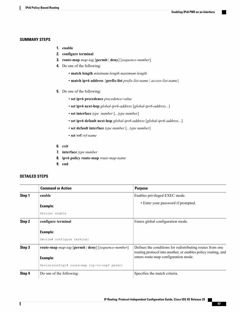
SUMMARY STEPS
1. enable2. configure terminal3. route-map map-tag [permit | deny] [sequence-number]4. Do one of the following:
• match length minimum-length maximum-length
• match ipv6 address {prefix-list prefix-list-name | access-list-name}
5. Do one of the following:
• set ipv6 precedence precedence-value
• set ipv6 next-hop global-ipv6-address [global-ipv6-address...]
• set interface type number [...type number]
• set ipv6 default next-hop global-ipv6-address [global-ipv6-address...]
• set default interface type number [...type number]
• set vrf vrf-name
6. exit7. interface type number8. ipv6 policy route-map route-map-name9. end
DETAILED STEPS
PurposeCommand or Action
Enables privileged EXEC mode.enableStep 1
Example:
Device> enable
• Enter your password if prompted.
Enters global configuration mode.configure terminal
Example:
Device# configure terminal
Step 2
Defines the conditions for redistributing routes from onerouting protocol into another, or enables policy routing, andenters route-map configuration mode.
route-map map-tag [permit | deny] [sequence-number]
Example:
Device(config)# route-map rip-to-ospf permit
Step 3
Specifies the match criteria.Do one of the following:Step 4
IP Routing: Protocol-Independent Configuration Guide, Cisco IOS XE Release 3S 97
IPv6 Policy-Based RoutingEnabling IPv6 PBR on an Interface
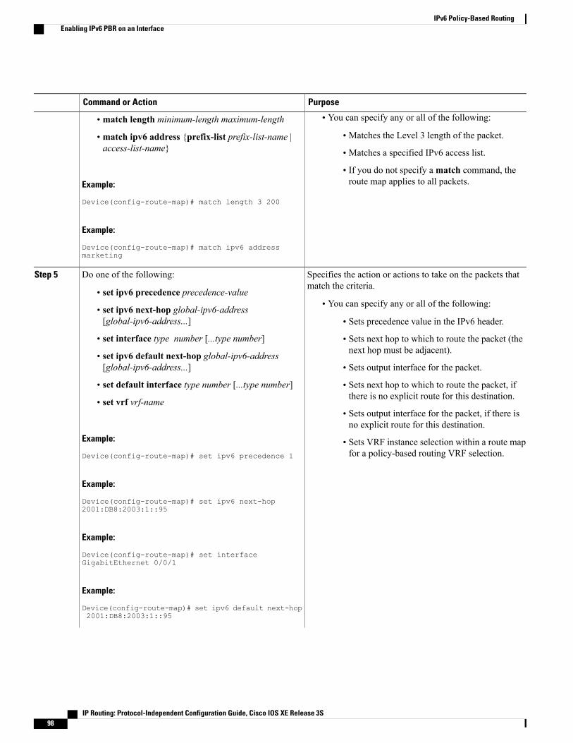
PurposeCommand or Action
• You can specify any or all of the following:• match length minimum-length maximum-length
• Matches the Level 3 length of the packet.• match ipv6 address {prefix-list prefix-list-name |access-list-name} • Matches a specified IPv6 access list.
• If you do not specify amatch command, theroute map applies to all packets.Example:
Device(config-route-map)# match length 3 200
Example:
Device(config-route-map)# match ipv6 addressmarketing
Specifies the action or actions to take on the packets thatmatch the criteria.
Do one of the following:Step 5
• set ipv6 precedence precedence-value• You can specify any or all of the following:• set ipv6 next-hop global-ipv6-address
[global-ipv6-address...] • Sets precedence value in the IPv6 header.
• set interface type number [...type number] • Sets next hop to which to route the packet (thenext hop must be adjacent).• set ipv6 default next-hop global-ipv6-address
[global-ipv6-address...] • Sets output interface for the packet.
• set default interface type number [...type number] • Sets next hop to which to route the packet, ifthere is no explicit route for this destination.• set vrf vrf-name
• Sets output interface for the packet, if there isno explicit route for this destination.
Example:
Device(config-route-map)# set ipv6 precedence 1
• Sets VRF instance selection within a route mapfor a policy-based routing VRF selection.
Example:
Device(config-route-map)# set ipv6 next-hop2001:DB8:2003:1::95
Example:
Device(config-route-map)# set interfaceGigabitEthernet 0/0/1
Example:
Device(config-route-map)# set ipv6 default next-hop2001:DB8:2003:1::95
IP Routing: Protocol-Independent Configuration Guide, Cisco IOS XE Release 3S98
IPv6 Policy-Based RoutingEnabling IPv6 PBR on an Interface
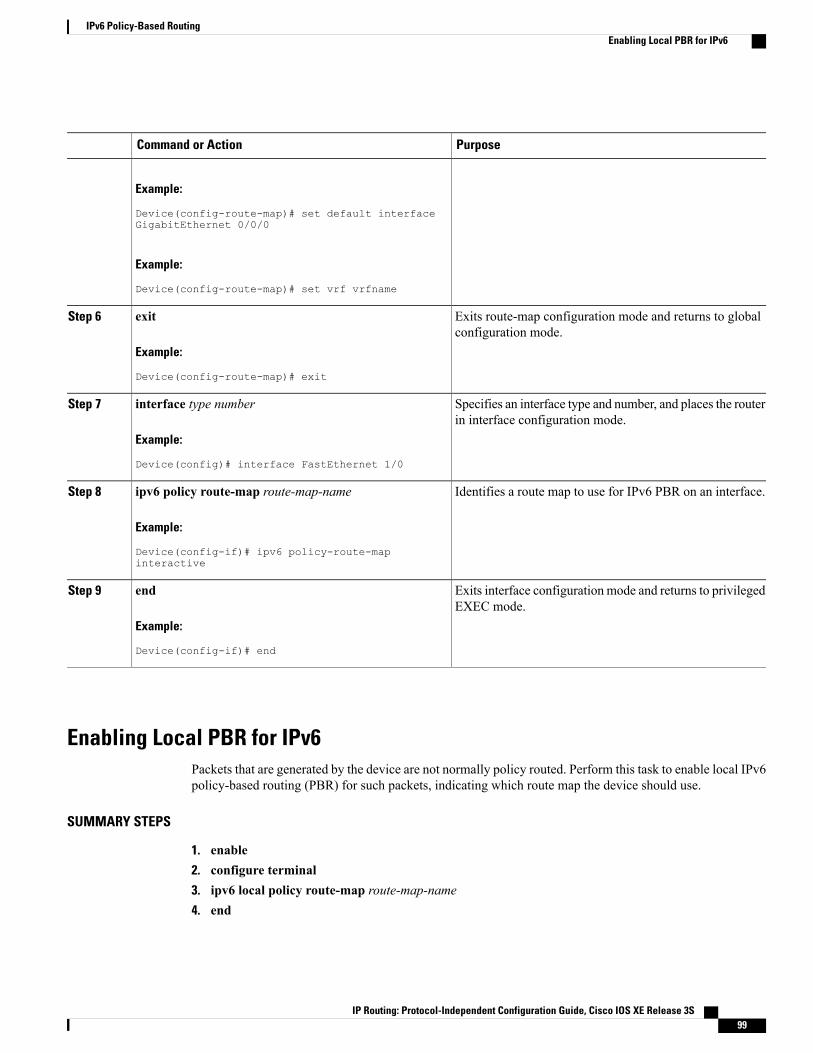
PurposeCommand or Action
Example:
Device(config-route-map)# set default interfaceGigabitEthernet 0/0/0
Example:
Device(config-route-map)# set vrf vrfname
Exits route-map configuration mode and returns to globalconfiguration mode.
exit
Example:
Device(config-route-map)# exit
Step 6
Specifies an interface type and number, and places the routerin interface configuration mode.
interface type number
Example:
Device(config)# interface FastEthernet 1/0
Step 7
Identifies a route map to use for IPv6 PBR on an interface.ipv6 policy route-map route-map-name
Example:
Device(config-if)# ipv6 policy-route-mapinteractive
Step 8
Exits interface configuration mode and returns to privilegedEXEC mode.
end
Example:
Device(config-if)# end
Step 9
Enabling Local PBR for IPv6Packets that are generated by the device are not normally policy routed. Perform this task to enable local IPv6policy-based routing (PBR) for such packets, indicating which route map the device should use.
SUMMARY STEPS
1. enable2. configure terminal3. ipv6 local policy route-map route-map-name4. end
IP Routing: Protocol-Independent Configuration Guide, Cisco IOS XE Release 3S 99
IPv6 Policy-Based RoutingEnabling Local PBR for IPv6

DETAILED STEPS
PurposeCommand or Action
Enables privileged EXEC mode.enableStep 1
Example:
Device> enable
• Enter your password if prompted.
Enters global configuration mode.configure terminal
Example:
Device# configure terminal
Step 2
Configures IPv6 PBR for packets generated by thedevice.
ipv6 local policy route-map route-map-name
Example:
Device(config)# ipv6 local policy route-mappbr-src-90
Step 3
Returns to privileged EXEC mode.end
Example:
Device(config)# end
Step 4
Verifying the Configuration and Operation of PBR for IPv6
SUMMARY STEPS
1. enable2. show ipv6 policy
DETAILED STEPS
PurposeCommand or Action
Enables privileged EXEC mode.enableStep 1
Example:
Device> enable
• Enter your password if prompted.
IP Routing: Protocol-Independent Configuration Guide, Cisco IOS XE Release 3S100
IPv6 Policy-Based RoutingVerifying the Configuration and Operation of PBR for IPv6

PurposeCommand or Action
Displays IPv6 policy routing packet activity.show ipv6 policy
Example:
Device# show ipv6 policy
Step 2
Troubleshooting PBR for IPv6Policy routing analyzes various parts of the packet and then routes the packet based on certain user-definedattributes in the packet.
SUMMARY STEPS
1. enable2. show route-map [map-name | dynamic [dynamic-map-name | application [application-name]] | all]
[detailed]3. debug ipv6 policy [access-list-name]
DETAILED STEPS
PurposeCommand or Action
Enables privileged EXEC mode.enableStep 1
Example:
Device> enable
• Enter your password if prompted.
Displays all route maps configured or only the onespecified.
show route-map [map-name | dynamic [dynamic-map-name| application [application-name]] | all] [detailed]
Example:
Device# show route-map
Step 2
Enables debugging of the IPv6 policy routing packetactivity.
debug ipv6 policy [access-list-name]
Example:
Device# debug ipv6 policy
Step 3
IP Routing: Protocol-Independent Configuration Guide, Cisco IOS XE Release 3S 101
IPv6 Policy-Based RoutingTroubleshooting PBR for IPv6

Configuration Examples for IPv6 Policy-Based Routing
Example: Enabling PBR on an InterfaceIn the following example, a route map named pbr-dest-1 is created and configured, specifying packet matchcriteria and desired policy-route action. PBR is then enabled on GigabitEthernet interface 0/0/1.
ipv6 access-list match-dest-1permit ipv6 any 2001:DB8:2001:1760::/32
route-map pbr-dest-1 permit 10match ipv6 address match-dest-1set interface GigabitEthernet 0/0/0
interface GigabitEthernet0/0/1ipv6 policy-route-map interactive
Example: Enabling Local PBR for IPv6In the following example, packets with a destination IPv6 address that match the IPv6 address range allowedby access list pbr-src-90 are sent to the device at IPv6 address 2001:DB8:2003:1::95:
ipv6 access-list src-90permit ipv6 host 2001:DB8:2003::90 2001:DB8:2001:1000::/64
route-map pbr-src-90 permit 10match ipv6 address src-90set ipv6 next-hop 2001:DB8:2003:1::95
ipv6 local policy route-map pbr-src-90
Example: show ipv6 policy Command OutputThe show ipv6 policy command displays PBR configuration, as shown in the following example:Device# show ipv6 policy
Interface RoutemapGigabitEthernet0/0/0 src-1
Example: Verifying Route-Map InformationThe following sample output from the show route-map command displays specific route-map information,such as a count of policy matches:
Device# show route-map
route-map bill, permit, sequence 10Match clauses:Set clauses:Policy routing matches:0 packets, 0 bytes
IP Routing: Protocol-Independent Configuration Guide, Cisco IOS XE Release 3S102
IPv6 Policy-Based RoutingConfiguration Examples for IPv6 Policy-Based Routing

Additional References for IPv6 Policy-Based RoutingRelated Documents
Document TitleRelated Topic
Cisco IOS Master Command List, All ReleasesCisco IOS commands
Cisco IOS IP Routing: Protocol-IndependentCommand Reference
IP Routing Protocol-Independent commands:complete command syntax, command mode,command history, defaults, usage guidelines, andexamples
MIBs
MIBs LinkMIBs
To locate and downloadMIBs for selected platforms,Cisco software releases, and feature sets, use CiscoMIB Locator found at the following URL:
http://www.cisco.com/go/mibs
No new or modified MIBs are supported by thisfeature, and support for existing MIBs has not beenmodified by this feature.
Technical Assistance
LinkDescription
http://www.cisco.com/cisco/web/support/index.htmlThe Cisco Support and Documentation websiteprovides online resources to download documentation,software, and tools. Use these resources to install andconfigure the software and to troubleshoot and resolvetechnical issues with Cisco products and technologies.Access to most tools on the Cisco Support andDocumentation website requires a Cisco.com user IDand password.
Feature Information for IPv6 Policy-Based RoutingThe following table provides release information about the feature or features described in this module. Thistable lists only the software release that introduced support for a given feature in a given software releasetrain. Unless noted otherwise, subsequent releases of that software release train also support that feature.
Use Cisco Feature Navigator to find information about platform support and Cisco software image support.To access Cisco Feature Navigator, go to . An account on Cisco.com is not required.
IP Routing: Protocol-Independent Configuration Guide, Cisco IOS XE Release 3S 103
IPv6 Policy-Based RoutingAdditional References for IPv6 Policy-Based Routing
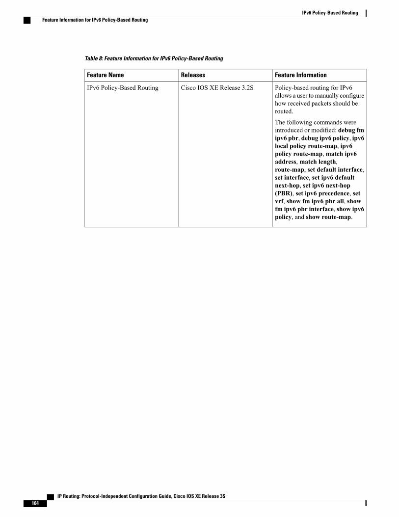
Table 8: Feature Information for IPv6 Policy-Based Routing
Feature InformationReleasesFeature Name
Policy-based routing for IPv6allows a user tomanually configurehow received packets should berouted.
The following commands wereintroduced or modified: debug fmipv6 pbr, debug ipv6 policy, ipv6local policy route-map, ipv6policy route-map, match ipv6address, match length,route-map, set default interface,set interface, set ipv6 defaultnext-hop, set ipv6 next-hop(PBR), set ipv6 precedence, setvrf, show fm ipv6 pbr all, showfm ipv6 pbr interface, show ipv6policy, and show route-map.
Cisco IOS XE Release 3.2SIPv6 Policy-Based Routing
IP Routing: Protocol-Independent Configuration Guide, Cisco IOS XE Release 3S104
IPv6 Policy-Based RoutingFeature Information for IPv6 Policy-Based Routing

C H A P T E R 9Multi-VRF Selection Using Policy-Based Routing
The Multi-VRF Selection Using Policy-Based Routing (PBR) feature allows a specified interface on aprovider edge (PE) device to route packets to Virtual Private Networks (VPNs) based on packet length ormatch criteria defined in an IP access list.
You can enable VPN routing and forwarding (VRF) selection by policy routing packets through a route map,through the global routing table, or to a specified VRF.
You can enable policy-routing packets for VRF instances by using route map commands with set commands.
On supported hardware, you can configure both theMulti-VRF Selection Using Policy-Based Routing featureand the MPLS VPN VRF Selection Based on a Source IP Address feature on the same interface.
• Finding Feature Information, page 105
• Prerequisites for Multi-VRF Selection Using Policy-Based Routing, page 106
• Restrictions for Multi-VRF Selection Using Policy-Based Routing, page 106
• Information About Multi-VRF Selection Using Policy-Based Routing, page 106
• How to Configure Multi-VRF Selection Using Policy-Based Routing, page 110
• Configuration Examples for Multi-VRF Selection Using Policy-Based Routing, page 118
• Additional References, page 119
• Feature Information for Multi-VRF Selection Using Policy-Based Routing, page 120
• Glossary, page 122
Finding Feature InformationYour software release may not support all the features documented in this module. For the latest caveats andfeature information, see Bug Search Tool and the release notes for your platform and software release. Tofind information about the features documented in this module, and to see a list of the releases in which eachfeature is supported, see the feature information table.
Use Cisco Feature Navigator to find information about platform support and Cisco software image support.To access Cisco Feature Navigator, go to www.cisco.com/go/cfn. An account on Cisco.com is not required.
IP Routing: Protocol-Independent Configuration Guide, Cisco IOS XE Release 3S 105
Prerequisites for Multi-VRF Selection Using Policy-BasedRouting
• The device must support policy-based routing (PBR) in order for you to configure this feature. Forplatforms that do not support PBR, use the MPLS VPN VRF Selection Based on a Source IP Addressfeature.
• AVirtual Private Network (VPN) virtual routing and forwarding (VRF) instance must be defined beforeyou configure this feature. An error message is displayed on the console if no VRF exists.
Restrictions for Multi-VRF Selection Using Policy-Based Routing• All commands that aid in routing also support hardware switching, except for the set ip next-hop verifyavailability command because Cisco Discovery Protocol information is not available in the line cards.
• Protocol Independent Multicast (PIM) and multicast packets do not support policy-based routing (PBR)and cannot be configured for a source IP address that is a match criterion for this feature.
• The set vrf and set ip global next-hop commands can be configured with the set default interface, setinterface , set ip default next-hop, and set ip next-hop commands. But the set vrf and set ip globalnext-hop commands take precedence over the set default interface, set interface , set ip defaultnext-hop, and set ip next-hop commands. No error message is displayed if you attempt to configurethe set vrf command with any of these three set commands.
• TheMulti-VRF Selection Using Policy-Based Routing feature cannot be configured with IP prefix lists.
• The set global and set vrf commands cannot be simultaneously applied to a route map.
• TheMulti-VRF Selection Using Policy-Based Routing feature supports VRF-lite; that is, only IP routingprotocols run on the device. Multiprotocol Label Switching (MPLS) and Virtual Private Networks(VPNs) cannot be configured. However, the set vrf command will work in MPLS VPN scenarios.
Information About Multi-VRF Selection Using Policy-BasedRouting
Policy Routing of VPN Traffic Based on Match CriteriaTheMulti-VRF SelectionUsing Policy-Based Routing feature is an extension of theMPLSVPNVRF SelectionBased on a Source IP Address feature. The Multi-VRF Selection Using Policy-Based Routing feature allowsyou to policy route Virtual Private Network (VPN) traffic based on match criteria. Match criteria are definedin an IP access list and/or are based on packet length. The following match criteria are supported in Ciscosoftware:
IP Routing: Protocol-Independent Configuration Guide, Cisco IOS XE Release 3S106
Multi-VRF Selection Using Policy-Based RoutingPrerequisites for Multi-VRF Selection Using Policy-Based Routing
• IP access lists—Define match criteria based on IP addresses, IP address ranges, and other IP packetaccess list filtering options. Named, numbered, standard, and extended access lists are supported. AllIP access list configuration options in Cisco software can be used to define match criteria.
• Packet lengths—Define match criteria based on the length of a packet, in bytes. The packet length filteris defined in a route map with thematch length route-map configuration command.
Policy routing is defined in the route map. The route map is applied to the incoming interface with the ippolicy route-map interface configuration command. An IP access list is applied to the route map with thematch ip address route-map configuration command. Packet length match criteria are applied to the routemap with thematch length route-map configuration command. The set action is defined with the set vrfroute-map configuration command. The match criteria are evaluated, and the appropriate VRF is selected bythe set command. This combination allows you to define match criteria for incoming VPN traffic and policyroute VPN packets out to the appropriate virtual routing and forwarding (VRF) instance.
Policy-Based Routing set Commands
Policy-routing Packets for VRF InstancesTo enable policy-routing packets for virtual routing and forwarding (VRF) instances, you can use route mapcommands with the following set commands. They are listed in the order in which the device uses them duringthe routing of packets.
• set tos—Sets the Type of Service (TOS) bits in the header of an IP packet.
• set df—Sets the Don’t Fragment (DF) bit in the header of an IP packet.
• set vrf—Routes packets through the specified interface. The destination interface can belong only to aVRF instance.
• set global—Routes packets through the global routing table. This command is useful for routing ingresspackets belonging to a specific VRF through the global routing table.
• set ip vrf next-hop—Indicates where to output IPv4 packets that pass a match criteria of a route mapfor policy routing when the IPv4 next hop must be under a specified VRF.
• set ipv6 vrf next-hop—Indicates where to output IPv6 packets that pass a match criteria of a route mapfor policy routing when the IPv6 next hop must be under a specified VRF.
• set ip global next-hop—Indicates where to forward IPv4 packets that pass a match criterion of a routemap for policy routing and for which the Cisco software uses the global routing table. The global keywordexplicitly defines that IPv4 next-hops are under the global routing table.
• set ipv6 global next-hop—Indicates where to forward IPv6 packets that pass a match criterion of aroute map for policy routing and for which the Cisco software uses the global routing table. The globalkeyword explicitly defines that IPv6 next-hops are under the global routing table.
• set interface—When packets enter a VRF, routes the packets out of the egress interface under the sameVRF according to the set interface policy, provided that the Layer 2 rewrite information is available.
• set ip default vrf—Provides IPv4 inherit-VRF and inter-VRF routing. With inherit-VRF routing, IPv4packets arriving at a VRF interface are routed by the same outgoing VRF interface. With inter-VRFrouting, IPv4 packets arriving at a VRF interface are routed through any other outgoing VRF interface.
IP Routing: Protocol-Independent Configuration Guide, Cisco IOS XE Release 3S 107
Multi-VRF Selection Using Policy-Based RoutingPolicy-Based Routing set Commands
• set ipv6 default vrf—Provides IPv6 inherit-VRF and inter-VRF routing. With inherit-VRF routing,IPv6 packets arriving at a VRF interface are routed by the same outgoing VRF interface.With inter-VRFrouting, IPv6 packets arriving at a VRF interface are routed through any other outgoing VRF interface.
• set ip default global—Provides IPv4 VRF to global routing.
• set ipv6 default global—Provides IPv6 VRF to global routing.
• set default interface—Indicates where to output packets that pass a match criterion of a route map forpolicy routing and have no explicit route to the destination. The interface can belong to any VRF.
• set ip default next-hop—Indicates where to output IPv4 packets that pass a match criterion of a routemap for policy routing and for which the Cisco software has no explicit route to a destination.
• set ipv6 default next-hop—Indicates where to IPv6 output packets that pass a match criterion of a routemap for policy routing and for which the Cisco software has no explicit route to a destination.
Change of Normal Routing and Forwarding BehaviorWhen you configure policy-based routing (PBR), you can use the following six set commands to changenormal routing and forwarding behavior. Configuring any of these set commands, with the potential exceptionof the set ip next-hop command, overrides the routing behavior of packets entering the interface if the packetsdo not belong to a virtual routing and forwarding (VRF) instance. The packets are routed from the egressinterface across the global routing table.
• set default interface—Indicates where to output packets that pass a match criterion of a route map forpolicy routing and have no explicit route to the destination.
• set interface—When packets enter a VRF interface, routes the packets out of the egress interface underthe same VRF according to the set interface policy, provided that the Layer 2 rewrite information isavailable.
The interface must be a peer-to-peer (P2P) interface.Note
• set ip default next-hop—Indicates where to output IPv4 packets that pass a match criterion of a routemap for policy routing and for which the Cisco software has no explicit route to a destination.
• set ipv6 default next-hop—Indicates where to output IPv6 packets that pass a match criterion of a routemap for policy routing and for which the Cisco software has no explicit route to a destination.
• set ip next-hop—Indicates where to output IPv4 packets that pass a match criterion of a route map forpolicy routing. If an IPv4 packet is received on a VRF interface and is transmitted from another interfacewithin the same VPN, the VRF context of the incoming packet is inherited from the interface.
• set ipv6 next-hop—Indicates where to output IPv6 packets that pass a match criterion of a route mapfor policy routing. If an IPv6 packet is received on a VRF interface and is transmitted from anotherinterface within the same Virtual Private Network (VPN), the VRF context of the incoming packet isinherited from the interface.
IP Routing: Protocol-Independent Configuration Guide, Cisco IOS XE Release 3S108
Multi-VRF Selection Using Policy-Based RoutingPolicy-Based Routing set Commands

Support of Inherit-VRF Inter-VRF and VRF-to-Global RoutingThe Multi-VRF Selection Using Policy-Based Routing (PBR) feature supports inherit-VRF and inter-VRF.With inherit-VRF routing, packets arriving at a virtual routing and forwarding (VRF) interface are routed bythe same outgoing VRF interface. With inter-VRF routing, packets arriving at a VRF interface are routedthrough any other outgoing VRF interface.
VRF-to-global routing causes packets that enter any VRF interface to be routed through the global routingtable. When a packet arrives on a VRF interface, the destination lookup normally is done only in thecorresponding VRF table. If a packet arrives on a global interface, the destination lookup is done in the globalrouting table.
TheMulti-VRF Selection Using Policy-Based Routing feature modifies the following set commands to supportinherit-VRF, inter-VRF, and VRF-to-global routing. The commands are listed in the order in which the deviceuses them during the routing of packets.
• set global—Routes packets through the global routing table. This command is useful for routing ingresspackets belonging to a specific VRF through the global routing table.
• set ip global next-hop—Indicates where to forward IPv4 packets that pass a match criterion of a routemap for policy routing and for which the Cisco software uses the global routing table.
• set ipv6 global next-hop—Indicates where to forward IPv6 packets that pass a match criterion of aroute map for policy routing and for which the Cisco software uses the global routing table.
• set ip vrf next-hop—Causes the device to look up the IPv4 next hop in the VRF table. If an IPv4 packetarrives on an interface that belongs to a VRF and the packet needs to be routed through a different VRF,you can use the set ip vrf next-hop command.
• set ipv6 vrf next-hop—Causes the device to look up the IPv6 next hop in the VRF table. If an IPv6packet arrives on an interface that belongs to a VRF and the packet needs to be routed through a differentVRF, you can use the set ipv6 vrf next-hop command.
• set ip default vrf—Provides IPv4 inherit-VRF and inter-VRF routing. With IPv4 inherit-VRF routing,IPv4 packets arriving at a VRF interface are routed by the same outgoing VRF interface.With inter-VRFrouting, IPv4 packets arriving at a VRF interface are routed through any other outgoing VRF interface.
• set ipv6 default vrf—Provides IPv6 inherit-VRF and inter-VRF routing.With IPv6 inherit-VRF routing,IPv6 packets arriving at a VRF interface are routed by the same outgoing VRF interface.With inter-VRFrouting, IPv6 packets arriving at a VRF interface are routed through any other outgoing VRF interface.
• set interface—When packets enter a VRF, routes the packets out of the egress interface under the sameVRF, according to the set interface policy, provided that the Layer 2 rewrite information is available.
• set default interface—Indicates where to output packets that pass a match criterion of a route map forpolicy routing and have no explicit route to the destination. The interface can belong to any VRF.
• set ip next-hop—Routes IPv4 packets through the global routing table in an IPv4-to-IPv4 routing andforwarding environment.
• set ipv6 next-hop—Routes IPv6 packets through the global routing table in an IPv6-to-IPv6 routingand forwarding environment.
• set vrf—Selects the appropriate VRF after a successful match occurs in the route map. VRS-aware PSVallows only inter-VRF (or VRF-to-VRF) switching.
IP Routing: Protocol-Independent Configuration Guide, Cisco IOS XE Release 3S 109
Multi-VRF Selection Using Policy-Based RoutingPolicy-Based Routing set Commands

How to Configure Multi-VRF Selection Using Policy-BasedRouting
Defining the Match Criteria for Multi-VRF Selection Using Policy-Based RoutingDefine the match criteria for the Multi-VRF Selection using Policy-Based Routing (PBR) feature so that youcan selectively route the packets instead of using their default routing and forwarding.
The match criteria for the Multi-VRF Selection using Policy-Based Routing are defined in an access list.Standard, named, and extended access lists are supported.
You can define the match criteria based on the packet length by configuring thematch length route-mapconfiguration command. This configuration option is defined entirely within a route map.
The following sections explain how to configure PBR route selection:
Configuring Multi-VRF Selection Using Policy-Based Routing with a Standard Access List
Before You Begin
The tasks in the following sections assume that the virtual routing and forwarding (VRF) instance and associatedIP address are already defined.
SUMMARY STEPS
1. enable2. configure terminal3. access-list access-list-number {deny | permit} [source source-wildcard] [log]
DETAILED STEPS
PurposeCommand or Action
Enables privileged EXEC mode.enableStep 1
Example:
Device> enable
• Enter your password if prompted.
Enters global configuration mode.configure terminal
Example:
Device# configure terminal
Step 2
Creates an access list and defines the match criteria for the route map.access-list access-list-number {deny | permit}[source source-wildcard] [log]
Step 3
IP Routing: Protocol-Independent Configuration Guide, Cisco IOS XE Release 3S110
Multi-VRF Selection Using Policy-Based RoutingHow to Configure Multi-VRF Selection Using Policy-Based Routing
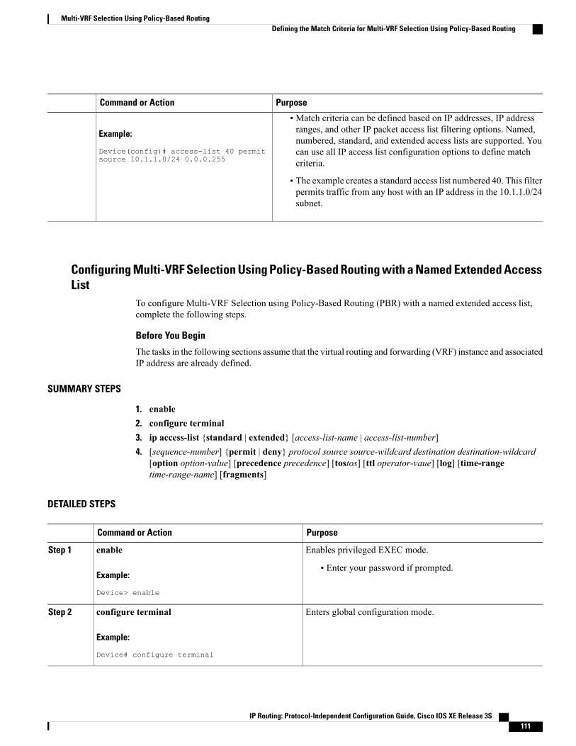
PurposeCommand or Action
• Match criteria can be defined based on IP addresses, IP addressranges, and other IP packet access list filtering options. Named,Example:
Device(config)# access-list 40 permitsource 10.1.1.0/24 0.0.0.255
numbered, standard, and extended access lists are supported. Youcan use all IP access list configuration options to define matchcriteria.
• The example creates a standard access list numbered 40. This filterpermits traffic from any host with an IP address in the 10.1.1.0/24subnet.
Configuring Multi-VRF Selection Using Policy-Based Routing with a Named Extended AccessList
To configure Multi-VRF Selection using Policy-Based Routing (PBR) with a named extended access list,complete the following steps.
Before You Begin
The tasks in the following sections assume that the virtual routing and forwarding (VRF) instance and associatedIP address are already defined.
SUMMARY STEPS
1. enable2. configure terminal3. ip access-list {standard | extended} [access-list-name | access-list-number]4. [sequence-number] {permit | deny} protocol source source-wildcard destination destination-wildcard
[option option-value] [precedence precedence] [tostos] [ttl operator-vaue] [log] [time-rangetime-range-name] [fragments]
DETAILED STEPS
PurposeCommand or Action
Enables privileged EXEC mode.enableStep 1
Example:
Device> enable
• Enter your password if prompted.
Enters global configuration mode.configure terminal
Example:
Device# configure terminal
Step 2
IP Routing: Protocol-Independent Configuration Guide, Cisco IOS XE Release 3S 111
Multi-VRF Selection Using Policy-Based RoutingDefining the Match Criteria for Multi-VRF Selection Using Policy-Based Routing
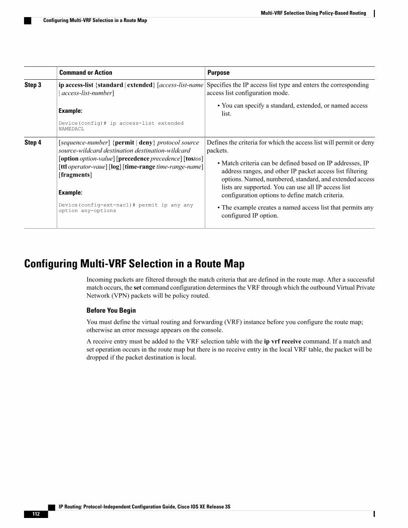
PurposeCommand or Action
Specifies the IP access list type and enters the correspondingaccess list configuration mode.
ip access-list {standard | extended} [access-list-name| access-list-number]
Step 3
Example:
Device(config)# ip access-list extendedNAMEDACL
• You can specify a standard, extended, or named accesslist.
Defines the criteria for which the access list will permit or denypackets.
[sequence-number] {permit | deny} protocol sourcesource-wildcard destination destination-wildcard
Step 4
[option option-value] [precedence precedence] [tostos]• Match criteria can be defined based on IP addresses, IPaddress ranges, and other IP packet access list filtering
[ttl operator-vaue] [log] [time-range time-range-name][fragments]
options. Named, numbered, standard, and extended access
Example:
Device(config-ext-nacl)# permit ip any anyoption any-options
lists are supported. You can use all IP access listconfiguration options to define match criteria.
• The example creates a named access list that permits anyconfigured IP option.
Configuring Multi-VRF Selection in a Route MapIncoming packets are filtered through the match criteria that are defined in the route map. After a successfulmatch occurs, the set command configuration determines the VRF through which the outbound Virtual PrivateNetwork (VPN) packets will be policy routed.
Before You Begin
You must define the virtual routing and forwarding (VRF) instance before you configure the route map;otherwise an error message appears on the console.
A receive entry must be added to the VRF selection table with the ip vrf receive command. If a match andset operation occurs in the route map but there is no receive entry in the local VRF table, the packet will bedropped if the packet destination is local.
IP Routing: Protocol-Independent Configuration Guide, Cisco IOS XE Release 3S112
Multi-VRF Selection Using Policy-Based RoutingConfiguring Multi-VRF Selection in a Route Map

SUMMARY STEPS
1. enable2. configure terminal3. route-map map-tag [permit | deny] [sequence-number]4. Do one of the following :
• set ip vrf vrf-name next-hop global-ipv4-address [...global-ipv4-address]
• set ipv6 vrf vrf-name next-hop global-ipv6-address [...global-ipv6-address]
• set ip next-hop recursive vrf global-ipv4-address [...global-ipv4-address]
• set ip global next-hop global-ipv4-address [...global-ipv4-address]
• set ipv6 global next-hop global-ipv6-address [...global-ipv6-address]
5. Do one of the following:
• match ip address {acl-number [acl-name | acl-number]}
• match length minimum-lengthmaximum-length
6. end
DETAILED STEPS
PurposeCommand or Action
Enables privileged EXEC mode.enableStep 1
Example:
Device> enable
• Enter your password if prompted.
Enters global configuration mode.configure terminal
Example:
Device# configure terminal
Step 2
Defines the conditions for redistributing routes from one routingprotocol into another, or enables policy routing.
route-mapmap-tag [permit | deny] [sequence-number]
Example:
Device(config)# route-map map1 permit 10
Step 3
• Enters route-map configuration mode.
Indicates where to forward packets that pass a match criterion ofa route map for policy routing when the IPv4 next hop must beunder a specified VRF.
Do one of the following :Step 4
• set ip vrf vrf-name next-hop global-ipv4-address[...global-ipv4-address]
Indicates where to forward packets that pass a match criterion ofa route map for policy routing when the IPv6 next hop must beunder a specified VRF.
• set ipv6 vrf vrf-name next-hop global-ipv6-address[...global-ipv6-address]
IP Routing: Protocol-Independent Configuration Guide, Cisco IOS XE Release 3S 113
Multi-VRF Selection Using Policy-Based RoutingConfiguring Multi-VRF Selection in a Route Map
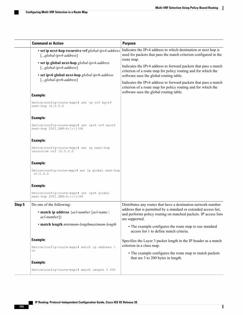
PurposeCommand or Action
Indicates the IPv4 address to which destination or next hop isused for packets that pass the match criterion configured in theroute map.
• set ip next-hop recursive vrf global-ipv4-address[...global-ipv4-address]
• set ip global next-hop global-ipv4-address[...global-ipv4-address] Indicates the IPv4 address to forward packets that pass a match
criterion of a route map for policy routing and for which thesoftware uses the global routing table.• set ipv6 global next-hop global-ipv6-address
[...global-ipv6-address]Indicates the IPv6 address to forward packets that pass a matchcriterion of a route map for policy routing and for which thesoftware uses the global routing table.
Example:
Device(config-route-map)# set ip vrf myvrfnext-hop 10.0.0.0
Example:
Device(config-route-map)# set ipv6 vrf myvrfnext-hop 2001.DB8:4:1::1/64
Example:
Device(config-route-map)# set ip next-hoprecursive vrf 10.0.0.0
Example:
Device(config-route-map)# set ip global next-hop10.0.0.0
Example:
Device(config-route-map)# set ipv6 globalnext-hop 2001.DB8:4:1::1/64
Distributes any routes that have a destination network numberaddress that is permitted by a standard or extended access list,
Do one of the following:Step 5
• match ip address {acl-number [acl-name |acl-number]}
and performs policy routing on matched packets. IP access listsare supported.
• match length minimum-lengthmaximum-length • The example configures the route map to use standardaccess list 1 to define match criteria.
Example:
Device(config-route-map)# match ip address 1or
Specifies the Layer 3 packet length in the IP header as a matchcriterion in a class map.
• The example configures the route map to match packetsthat are 3 to 200 bytes in length.
Example:
Device(config-route-map)# match length 3 200
IP Routing: Protocol-Independent Configuration Guide, Cisco IOS XE Release 3S114
Multi-VRF Selection Using Policy-Based RoutingConfiguring Multi-VRF Selection in a Route Map

PurposeCommand or Action
Returns to privileged EXEC mode.end
Example:
Device(config-route-map)# end
Step 6
Configuring Multi-VRF Selection Using Policy-Based Routing and IP VRFReceive on the Interface
The route map is attached to the incoming interface with the ip policy route-map interface configurationcommand.
The source IP address must be added to the virtual routing and forwarding (VRF) selection table. VRF selectionis a one-way (unidirectional) feature. It is applied to the incoming interface. If amatch and set operationoccurs in the route map but there is no receive entry in the local VRF table, the packet is dropped if the packetdestination is local.
SUMMARY STEPS
1. enable2. configure terminal3. interface type number [name-tag]4. ip policy route-map map-tag5. ip vrf receive vrf-name6. end
DETAILED STEPS
PurposeCommand or Action
Enables privileged EXEC mode.enableStep 1
Example:
Device> enable
• Enter your password if prompted.
Enters global configuration mode.configure terminal
Example:
Device# configure terminal
Step 2
IP Routing: Protocol-Independent Configuration Guide, Cisco IOS XE Release 3S 115
Multi-VRF Selection Using Policy-Based RoutingConfiguring Multi-VRF Selection Using Policy-Based Routing and IP VRF Receive on the Interface
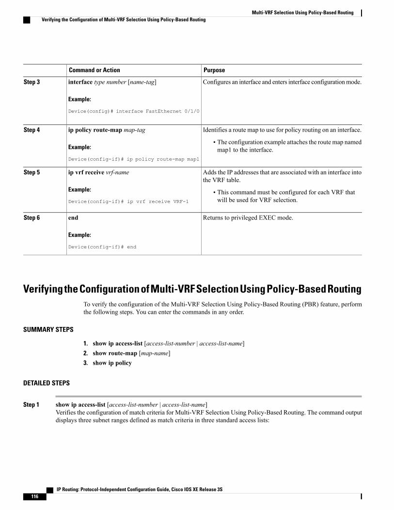
PurposeCommand or Action
Configures an interface and enters interface configurationmode.interface type number [name-tag]
Example:
Device(config)# interface FastEthernet 0/1/0
Step 3
Identifies a route map to use for policy routing on an interface.ip policy route-map map-tagStep 4
Example:
Device(config-if)# ip policy route-map map1
• The configuration example attaches the route map namedmap1 to the interface.
Adds the IP addresses that are associated with an interface intothe VRF table.
ip vrf receive vrf-name
Example:
Device(config-if)# ip vrf receive VRF-1
Step 5
• This command must be configured for each VRF thatwill be used for VRF selection.
Returns to privileged EXEC mode.end
Example:
Device(config-if)# end
Step 6
Verifying the Configuration of Multi-VRF Selection Using Policy-Based RoutingTo verify the configuration of the Multi-VRF Selection Using Policy-Based Routing (PBR) feature, performthe following steps. You can enter the commands in any order.
SUMMARY STEPS
1. show ip access-list [access-list-number | access-list-name]2. show route-map [map-name]3. show ip policy
DETAILED STEPS
Step 1 show ip access-list [access-list-number | access-list-name]Verifies the configuration of match criteria for Multi-VRF Selection Using Policy-Based Routing. The command outputdisplays three subnet ranges defined as match criteria in three standard access lists:
IP Routing: Protocol-Independent Configuration Guide, Cisco IOS XE Release 3S116
Multi-VRF Selection Using Policy-Based RoutingVerifying the Configuration of Multi-VRF Selection Using Policy-Based Routing
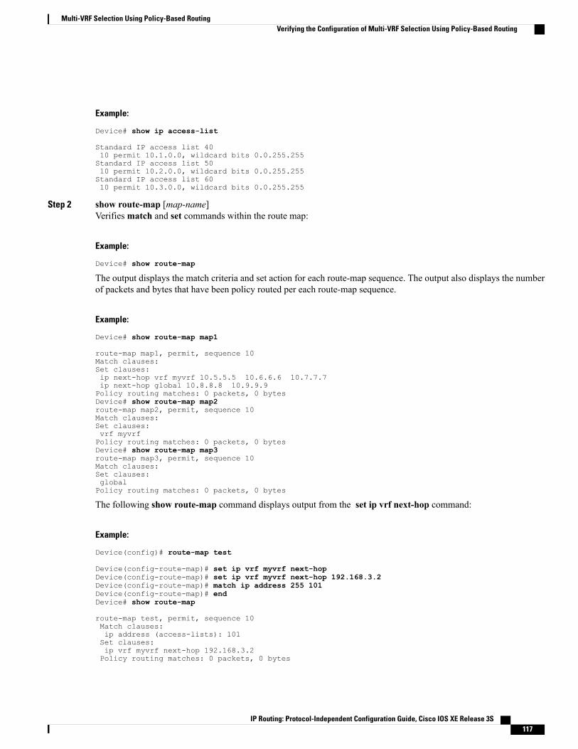
Example:
Device# show ip access-list
Standard IP access list 4010 permit 10.1.0.0, wildcard bits 0.0.255.255Standard IP access list 5010 permit 10.2.0.0, wildcard bits 0.0.255.255Standard IP access list 6010 permit 10.3.0.0, wildcard bits 0.0.255.255
Step 2 show route-map [map-name]Verifiesmatch and set commands within the route map:
Example:
Device# show route-map
The output displays the match criteria and set action for each route-map sequence. The output also displays the numberof packets and bytes that have been policy routed per each route-map sequence.
Example:
Device# show route-map map1
route-map map1, permit, sequence 10Match clauses:Set clauses:ip next-hop vrf myvrf 10.5.5.5 10.6.6.6 10.7.7.7ip next-hop global 10.8.8.8 10.9.9.9Policy routing matches: 0 packets, 0 bytesDevice# show route-map map2route-map map2, permit, sequence 10Match clauses:Set clauses:vrf myvrfPolicy routing matches: 0 packets, 0 bytesDevice# show route-map map3route-map map3, permit, sequence 10Match clauses:Set clauses:globalPolicy routing matches: 0 packets, 0 bytes
The following show route-map command displays output from the set ip vrf next-hop command:
Example:
Device(config)# route-map test
Device(config-route-map)# set ip vrf myvrf next-hopDevice(config-route-map)# set ip vrf myvrf next-hop 192.168.3.2Device(config-route-map)# match ip address 255 101Device(config-route-map)# endDevice# show route-map
route-map test, permit, sequence 10Match clauses:ip address (access-lists): 101Set clauses:ip vrf myvrf next-hop 192.168.3.2Policy routing matches: 0 packets, 0 bytes
IP Routing: Protocol-Independent Configuration Guide, Cisco IOS XE Release 3S 117
Multi-VRF Selection Using Policy-Based RoutingVerifying the Configuration of Multi-VRF Selection Using Policy-Based Routing
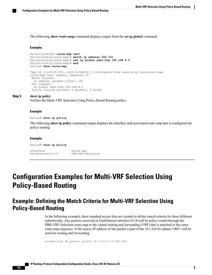
The following show route-map command displays output from the set ip global command:
Example:
Device(config)# route-map testDevice(config-route-map)# match ip address 255 101Device(config-route-map)# set ip global next-hop 192.168.4.2Device(config-route-map)# endDevice# show route-map
*May 25 13:45:55.551: %SYS-5-CONFIG_I: Configured from console by consoleout-maproute-map test, permit, sequence 10Match clauses:ip address (access-lists): 101Set clauses:ip global next-hop 192.168.4.2Policy routing matches: 0 packets, 0 bytes
Step 3 show ip policyVerifies the Multi-VRF Selection Using Policy-Based Routing policy.
Example:
Device# show ip policy
The following show ip policy command output displays the interface and associated route map that is configured forpolicy routing:
Example:
Device# show ip policy
Interface Route mapFastEthernet0/1/0 PBR-VRF-Selection
Configuration Examples for Multi-VRF Selection UsingPolicy-Based Routing
Example: Defining the Match Criteria for Multi-VRF Selection UsingPolicy-Based Routing
In the following example, three standard access lists are created to define match criteria for three differentsubnetworks. Any packets received on FastEthernet interface 0/1/0 will be policy routed through thePBR-VRF-Selection route map to the virtual routing and forwarding (VRF) that is matched in the sameroute-map sequence. If the source IP address of the packet is part of the 10.1.0.0/24 subnet, VRF1 will beused for routing and forwarding.
access-list 40 permit source 10.1.0.0 0.0.255.255
IP Routing: Protocol-Independent Configuration Guide, Cisco IOS XE Release 3S118
Multi-VRF Selection Using Policy-Based RoutingConfiguration Examples for Multi-VRF Selection Using Policy-Based Routing
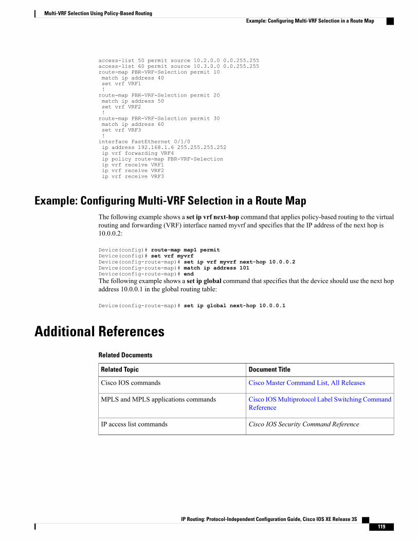
access-list 50 permit source 10.2.0.0 0.0.255.255access-list 60 permit source 10.3.0.0 0.0.255.255route-map PBR-VRF-Selection permit 10match ip address 40set vrf VRF1!route-map PBR-VRF-Selection permit 20match ip address 50set vrf VRF2!route-map PBR-VRF-Selection permit 30match ip address 60set vrf VRF3!interface FastEthernet 0/1/0ip address 192.168.1.6 255.255.255.252ip vrf forwarding VRF4ip policy route-map PBR-VRF-Selectionip vrf receive VRF1ip vrf receive VRF2ip vrf receive VRF3
Example: Configuring Multi-VRF Selection in a Route MapThe following example shows a set ip vrf next-hop command that applies policy-based routing to the virtualrouting and forwarding (VRF) interface named myvrf and specifies that the IP address of the next hop is10.0.0.2:
Device(config)# route-map map1 permitDevice(config)# set vrf myvrfDevice(config-route-map)# set ip vrf myvrf next-hop 10.0.0.2Device(config-route-map)# match ip address 101Device(config-route-map)# endThe following example shows a set ip global command that specifies that the device should use the next hopaddress 10.0.0.1 in the global routing table:
Device(config-route-map)# set ip global next-hop 10.0.0.1
Additional ReferencesRelated Documents
Document TitleRelated Topic
Cisco Master Command List, All ReleasesCisco IOS commands
Cisco IOSMultiprotocol Label Switching CommandReference
MPLS and MPLS applications commands
Cisco IOS Security Command ReferenceIP access list commands
IP Routing: Protocol-Independent Configuration Guide, Cisco IOS XE Release 3S 119
Multi-VRF Selection Using Policy-Based RoutingExample: Configuring Multi-VRF Selection in a Route Map

Technical Assistance
LinkDescription
http://www.cisco.com/cisco/web/support/index.htmlThe Cisco Support and Documentation websiteprovides online resources to download documentation,software, and tools. Use these resources to install andconfigure the software and to troubleshoot and resolvetechnical issues with Cisco products and technologies.Access to most tools on the Cisco Support andDocumentation website requires a Cisco.com user IDand password.
Feature Information for Multi-VRF Selection Using Policy-BasedRouting
The following table provides release information about the feature or features described in this module. Thistable lists only the software release that introduced support for a given feature in a given software releasetrain. Unless noted otherwise, subsequent releases of that software release train also support that feature.
Use Cisco Feature Navigator to find information about platform support and Cisco software image support.To access Cisco Feature Navigator, go to . An account on Cisco.com is not required.
IP Routing: Protocol-Independent Configuration Guide, Cisco IOS XE Release 3S120
Multi-VRF Selection Using Policy-Based RoutingFeature Information for Multi-VRF Selection Using Policy-Based Routing
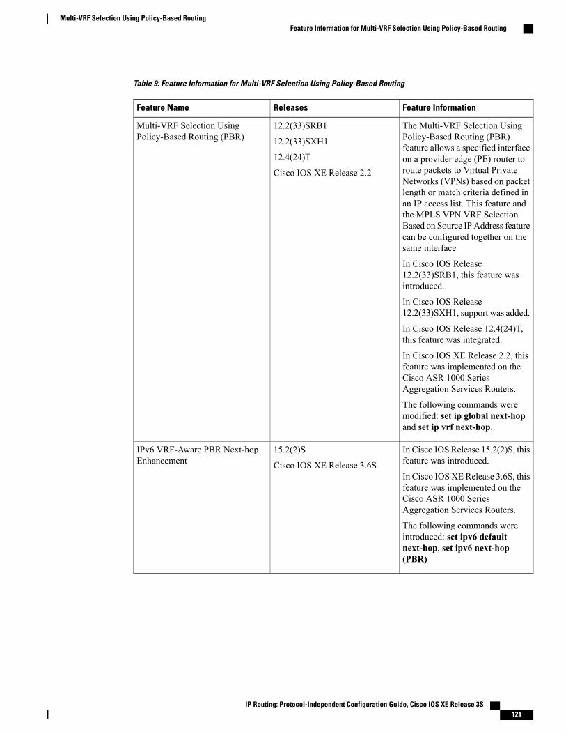
Table 9: Feature Information for Multi-VRF Selection Using Policy-Based Routing
Feature InformationReleasesFeature Name
The Multi-VRF Selection UsingPolicy-Based Routing (PBR)feature allows a specified interfaceon a provider edge (PE) router toroute packets to Virtual PrivateNetworks (VPNs) based on packetlength or match criteria defined inan IP access list. This feature andthe MPLS VPN VRF SelectionBased on Source IPAddress featurecan be configured together on thesame interface
In Cisco IOS Release12.2(33)SRB1, this feature wasintroduced.
In Cisco IOS Release12.2(33)SXH1, support was added.
In Cisco IOS Release 12.4(24)T,this feature was integrated.
In Cisco IOS XE Release 2.2, thisfeature was implemented on theCisco ASR 1000 SeriesAggregation Services Routers.
The following commands weremodified: set ip global next-hopand set ip vrf next-hop.
12.2(33)SRB1
12.2(33)SXH1
12.4(24)T
Cisco IOS XE Release 2.2
Multi-VRF Selection UsingPolicy-Based Routing (PBR)
In Cisco IOS Release 15.2(2)S, thisfeature was introduced.
In Cisco IOSXERelease 3.6S, thisfeature was implemented on theCisco ASR 1000 SeriesAggregation Services Routers.
The following commands wereintroduced: set ipv6 defaultnext-hop, set ipv6 next-hop(PBR)
15.2(2)S
Cisco IOS XE Release 3.6S
IPv6 VRF-Aware PBR Next-hopEnhancement
IP Routing: Protocol-Independent Configuration Guide, Cisco IOS XE Release 3S 121
Multi-VRF Selection Using Policy-Based RoutingFeature Information for Multi-VRF Selection Using Policy-Based Routing

GlossaryCE device—customer edge device. A device that is part of a customer network and that interfaces to a provideredge (PE) device.
Inherit-VRF routing—Packets arriving at a VRF interface are routed by the same outgoing VRF interface.
Inter-VRF routing—Packets arriving at a VRF interface are routed via any other outgoing VRF interface.
IP—Internet Protocol. Network layer protocol in the TCP/IP stack offering a connectionless internetworkservice. IP provides features for addressing, type-of-service specification, fragmentation and reassembly, andsecurity. Defined in RFC 791.
PBR—policy-based routing. PBR allows a user to manually configure how received packets should be routed.
PE device—provider edge device. A device that is part of a service provider’s network and that is connectedto a CE device. It exchanges routing information with CE devices by using static routing or a routing protocolsuch as BGP, RIPv1, or RIPv2.
VPN—Virtual Private Network. A collection of sites sharing a common routing table. A VPN provides asecure way for customers to share bandwidth over an ISP backbone network.
VRF—A VPN routing and forwarding instance. A VRF consists of an IP routing table, a derived forwardingtable, a set of interfaces that use the forwarding table, and a set of rules and routing protocols that determinewhat goes into the forwarding table.
VRF-lite—A feature that enables a service provider to support two or more VPNs, where IP addresses canbe overlapped among the VPNs.
IP Routing: Protocol-Independent Configuration Guide, Cisco IOS XE Release 3S122
Multi-VRF Selection Using Policy-Based RoutingGlossary
C H A P T E R 10Multi-VRF Support
The Multi-VRF Support feature allows you to configure and maintain more than one instance of a routingand forwarding table within the same customer edge (CE) device.
• Finding Feature Information, page 123
• Prerequisites for Multi-VRF Support, page 123
• Restrictions for Multi-VRF Support, page 124
• Information About Multi-VRF Support, page 124
• How to Configure Multi-VRF Support, page 126
• Configuration Examples for Multi-VRF Support, page 135
• Additional References, page 138
• Feature Information for Multi-VRF Support, page 139
Finding Feature InformationYour software release may not support all the features documented in this module. For the latest caveats andfeature information, see Bug Search Tool and the release notes for your platform and software release. Tofind information about the features documented in this module, and to see a list of the releases in which eachfeature is supported, see the feature information table.
Use Cisco Feature Navigator to find information about platform support and Cisco software image support.To access Cisco Feature Navigator, go to www.cisco.com/go/cfn. An account on Cisco.com is not required.
Prerequisites for Multi-VRF SupportThe network’s core and provider edge (PE) devices must be configured for Virtual Private Network (VPN)operation.
IP Routing: Protocol-Independent Configuration Guide, Cisco IOS XE Release 3S 123

Restrictions for Multi-VRF Support• You can configure the Multi-VRF Support feature only on Layer 3 interfaces.
• The Multi-VRF Support feature is not supported by Interior Gateway Routing Protocol (IGRP) norIntermediate System to Intermediate System (IS-IS).
• Label distribution for a given VPN routing and forwarding (VRF) instance on a given device can behandled by either Border Gateway Protocol (BGP) or Label Distribution Protocol (LDP), but not byboth protocols at the same time.
• Multicast cannot operate on a Layer 3 interface that is configured with the Multi-VRF Support feature.
Information About Multi-VRF Support
How the Multi-VRF Support Feature WorksThe Multi-VRF Support feature enables a service provider to support two or more Virtual Private Networks(VPNs), where the IP addresses can overlap several VPNs. TheMulti-VRF Support feature uses input interfacesto distinguish routes for different VPNs and forms virtual packet-forwarding tables by associating one or moreLayer 3 interfaces with each virtual routing and forwarding (VRF) instance. Interfaces in a VRF can be eitherphysical, such as FastEthernet ports, or logical, such as VLAN switched virtual interfaces (SVIs), but a Layer3 interface cannot belong to more than one VRF at any one time. The Multi-VRF Support feature allows anoperator to support two or more routing domains on a customer edge (CE) device, with each routing domainhaving its own set of interfaces and its own set of routing and forwarding tables. The Multi-VRF Supportfeature makes it possible to extend the label switched paths (LSPs) to the CE and into each routing domainthat the CE supports.
The Multi-VRF Support feature works as follows:
• Each CE device advertises its site’s local routes to a provider edge (PE) device and learns the remoteVPN routes from that provider edge (PE) device.
• PE devices exchange routing information with CE devices by using static routing or a routing protocolsuch as the Border Gateway Protocol (BGP), Routing Information Protocol version 1 (RIPv1), or RIPv2.
• PE devices exchange MPLS label information with CE devices through Label Distribution Protocol(LDP) or BGP.
• The PE device needs to maintain VPN routes only for those VPNs to which it is directly attached,eliminating the requirement that the PE maintain all of the service provider’s VPN routes. Each PEdevice maintains a VRF for each of its directly connected sites. Two or more interfaces on a PE devicecan be associated with a single VRF if all the sites participate in the same VPN. Each VPN is mappedto a specified VRF. After learning local VPN routes from CE devices, the PE device exchanges VPNrouting information with other PE devices through internal BGP (iBGP).
With the Multi-VRF Support feature, two or more customers can share one CE device, and only one physicallink is used between the CE and the PE devices. The shared CE device maintains separate VRF tables foreach customer and routes packets for each customer based on that customer’s own routing table. TheMulti-VRF
IP Routing: Protocol-Independent Configuration Guide, Cisco IOS XE Release 3S124
Multi-VRF SupportRestrictions for Multi-VRF Support

Support feature extends limited PE device functionality to a CE device, giving it the ability, through themaintenance of separate VRF tables, to extend the privacy and security of a VPN to the branch office.
The figure below shows a configuration where each CE device acts as if it were two CE devices. Because theMulti-VRF Support feature is a Layer 3 feature, each interface associated with a VRF must be a Layer 3interface.
Figure 7: Each CE Device Acting as Several Virtual CE Devices
How Packets Are Forwarded in a Network Using the Multi-VRF Support FeatureFollowing is the packet-forwarding process in anMulti-VRF customer edge (CE)-enabled network, as illustratedin the figure above:
• When the CE receives a packet from a Virtual Private Network (VPN), it looks up the routing tablebased on the input interface. When a route is found, the CE imposes the Multiprotocol Label Switching(MPLS) label that it received from the provider edge (PE) for that route and forwards the packet to thePE.
• When the ingress PE receives a packet from the CE, it swaps the incoming label with the correspondinglabel stack and sends the packet to the MPLS network.
• When an egress PE receives a packet from the network, it swaps the VPN label with the label that it hadearlier received for the route from the CE, and it forwards the packet to the CE.
• When a CE receives a packet from an egress PE, it uses the incoming label on the packet to forward thepacket to the correct VPN.
To configure Multi-VRF, you create a VRF table and then specify the Layer 3 interface associated with thatVRF. Next, you configure the routing protocols within the VPN, and between the CE and the PE. The BorderGateway Protocol (BGP) is the preferred routing protocol for distributing VPN routing information acrossthe provider’s backbone.The Multi-VRF network has three major components:
• VPN route target communities: These are lists of all other members of a VPN community. You mustconfigure VPN route targets for each VPN community member.
IP Routing: Protocol-Independent Configuration Guide, Cisco IOS XE Release 3S 125
Multi-VRF SupportHow Packets Are Forwarded in a Network Using the Multi-VRF Support Feature
• Multiprotocol BGP peering of VPN community PE devices: This propagates VRF reachability informationto all members of a VPN community. You must configure BGP peering in all PE devices within a VPNcommunity.
• VPN forwarding: This transports all traffic between VPN community members across a VPNservice-provider network.
Considerations When Configuring the Multi-VRF Support Feature• A device with the Multi-VRF Support feature is shared by several customers, and each customer has itsown routing table.
• Because each customer uses a different virtual routing and forwarding (VRF) table, the same IP addressescan be reused. Overlapping IP addresses are allowed in different Virtual Private Networks (VPNs).
• TheMulti-VRF Support feature lets several customers share the same physical link between the provideredge (PE) and the customer edge (CE) devices. Trunk ports with several VLANs separate packets amongthe customers. Each customer has its own VLAN.
• For the PE device, there is no difference between using the Multi-VRF Support feature or using severalCE devices.
• The Multi-VRF Support feature does not affect the packet-switching rate.
How to Configure Multi-VRF Support
Configuring VRFsTo configure virtual routing and forwarding (VRF) instances, complete the following procedure. Be sure toconfigure VRFs on both the provider edge (PE) and customer edge (CE) devices.
If a VRF has not been configured, the device has the following default configuration:
• No VRFs have been defined.
• No import maps, export maps, or route maps have been defined.
• No VRF maximum routes exist.
• Only the global routing table exists on the interface.
Multicast cannot be configured at the same time on the same Layer 3 interface as the Multi-VRF Supportfeature.
Note
IP Routing: Protocol-Independent Configuration Guide, Cisco IOS XE Release 3S126
Multi-VRF SupportConsiderations When Configuring the Multi-VRF Support Feature
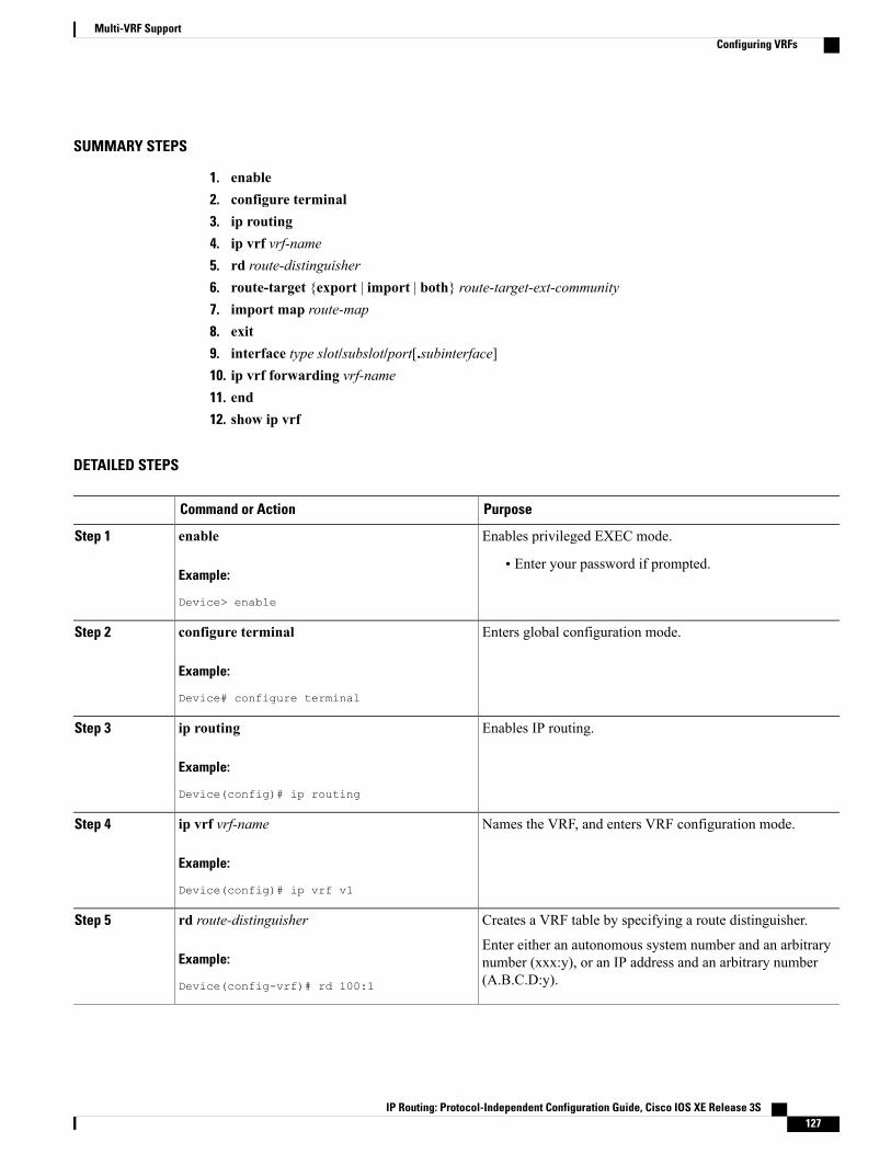
SUMMARY STEPS
1. enable2. configure terminal3. ip routing4. ip vrf vrf-name5. rd route-distinguisher6. route-target {export | import | both} route-target-ext-community7. import map route-map8. exit9. interface type slot/subslot/port[.subinterface]10. ip vrf forwarding vrf-name11. end12. show ip vrf
DETAILED STEPS
PurposeCommand or Action
Enables privileged EXEC mode.enableStep 1
Example:
Device> enable
• Enter your password if prompted.
Enters global configuration mode.configure terminal
Example:
Device# configure terminal
Step 2
Enables IP routing.ip routing
Example:
Device(config)# ip routing
Step 3
Names the VRF, and enters VRF configuration mode.ip vrf vrf-name
Example:
Device(config)# ip vrf v1
Step 4
Creates a VRF table by specifying a route distinguisher.rd route-distinguisherStep 5
Example:
Device(config-vrf)# rd 100:1
Enter either an autonomous system number and an arbitrarynumber (xxx:y), or an IP address and an arbitrary number(A.B.C.D:y).
IP Routing: Protocol-Independent Configuration Guide, Cisco IOS XE Release 3S 127
Multi-VRF SupportConfiguring VRFs
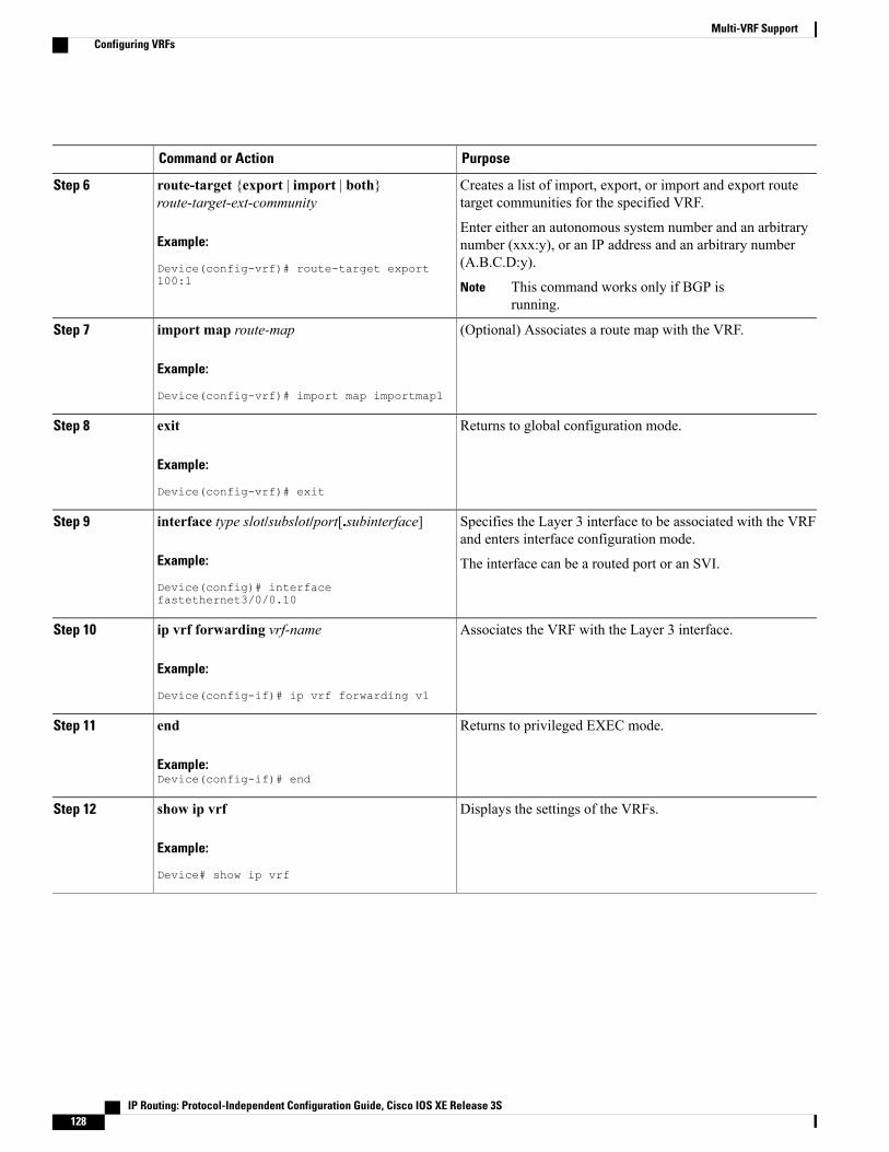
PurposeCommand or Action
Creates a list of import, export, or import and export routetarget communities for the specified VRF.
route-target {export | import | both}route-target-ext-community
Step 6
Example:
Device(config-vrf)# route-target export100:1
Enter either an autonomous system number and an arbitrarynumber (xxx:y), or an IP address and an arbitrary number(A.B.C.D:y).
This command works only if BGP isrunning.
Note
(Optional) Associates a route map with the VRF.import map route-map
Example:
Device(config-vrf)# import map importmap1
Step 7
Returns to global configuration mode.exit
Example:
Device(config-vrf)# exit
Step 8
Specifies the Layer 3 interface to be associated with the VRFand enters interface configuration mode.
interface type slot/subslot/port[.subinterface]
Example:
Device(config)# interfacefastethernet3/0/0.10
Step 9
The interface can be a routed port or an SVI.
Associates the VRF with the Layer 3 interface.ip vrf forwarding vrf-name
Example:
Device(config-if)# ip vrf forwarding v1
Step 10
Returns to privileged EXEC mode.end
Example:Device(config-if)# end
Step 11
Displays the settings of the VRFs.show ip vrf
Example:
Device# show ip vrf
Step 12
IP Routing: Protocol-Independent Configuration Guide, Cisco IOS XE Release 3S128
Multi-VRF SupportConfiguring VRFs

Configuring BGP as the Routing ProtocolMost routing protocols can be used between the customer edge (CE) and the provider edge (PE) devices.However, external BGP (eBGP) is recommended, because:
• BGP does not require more than one algorithm to communicate with many CE devices.
• BGP is designed to pass routing information between systems run by different administrations.
• BGP makes it easy to pass route attributes to the CE device.
When BGP is used as the routing protocol, it can also be used to handle the Multiprotocol Label Switching(MPLS) label exchange between the PE and CE devices. By contrast, if Open Shortest Path First (OSPF),Enhanced Interior Gateway Routing Protocol (EIGRP), Routing Information Protocol (RIP), or static routingis used, the Label Distribution Protocol (LDP) must be used to signal labels.
To configure a BGP PE-to-CE routing session, perform the following steps on the CE and on the PE devices.
SUMMARY STEPS
1. enable2. configure terminal3. router bgp autonomous-system-number4. network ip-addressmask network-mask5. redistribute ospf process-idmatch internal6. network ip-address wildcard-mask area area-id7. address-family ipv4 vrf vrf-name8. neighbor {ip-address | peer-group-name} remote-as as-number9. neighbor address activate
DETAILED STEPS
PurposeCommand or Action
Enables privileged EXEC mode.enableStep 1
Example:
Device> enable
• Enter your password if prompted.
Enters global configuration mode.configure terminal
Example:
Device# configure terminal
Step 2
IP Routing: Protocol-Independent Configuration Guide, Cisco IOS XE Release 3S 129
Multi-VRF SupportConfiguring BGP as the Routing Protocol
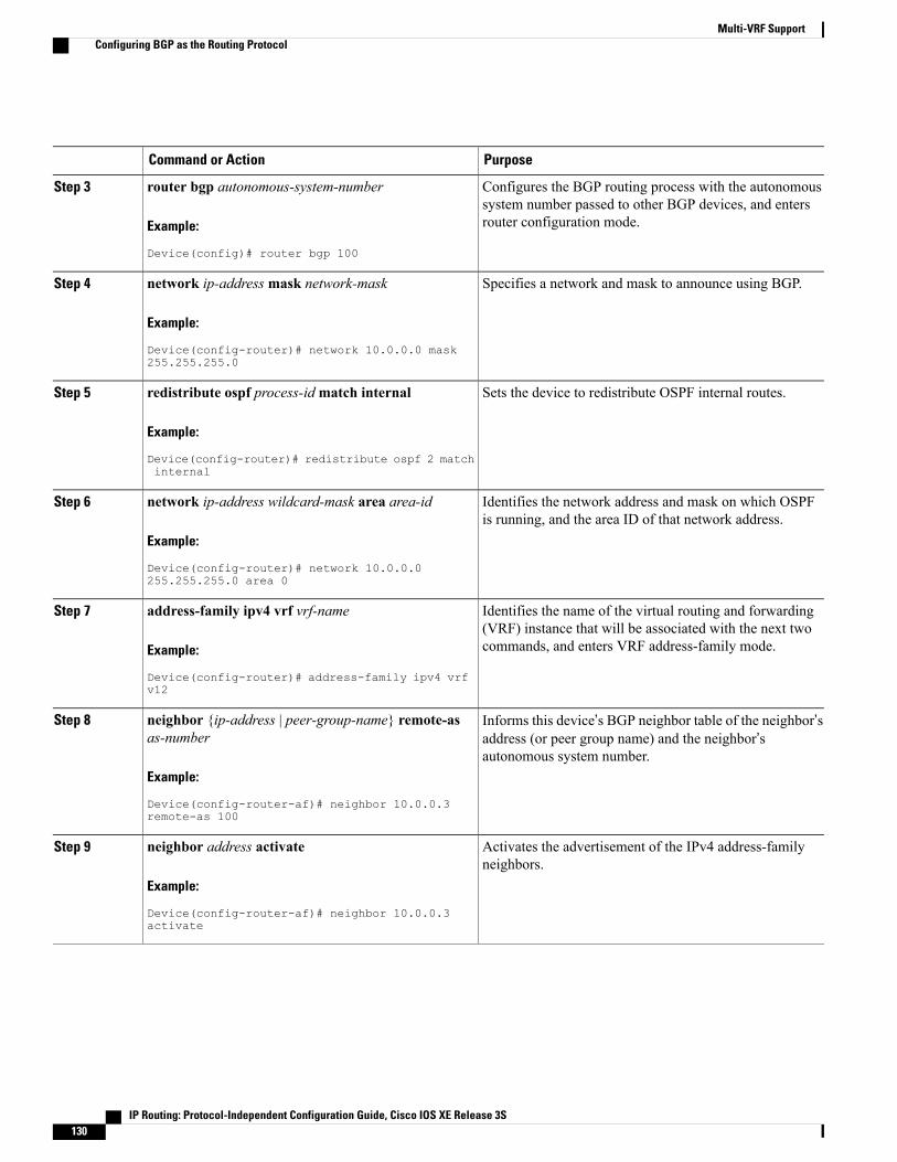
PurposeCommand or Action
Configures the BGP routing process with the autonomoussystem number passed to other BGP devices, and entersrouter configuration mode.
router bgp autonomous-system-number
Example:
Device(config)# router bgp 100
Step 3
Specifies a network and mask to announce using BGP.network ip-addressmask network-mask
Example:
Device(config-router)# network 10.0.0.0 mask255.255.255.0
Step 4
Sets the device to redistribute OSPF internal routes.redistribute ospf process-idmatch internal
Example:
Device(config-router)# redistribute ospf 2 matchinternal
Step 5
Identifies the network address and mask on which OSPFis running, and the area ID of that network address.
network ip-address wildcard-mask area area-id
Example:
Device(config-router)# network 10.0.0.0255.255.255.0 area 0
Step 6
Identifies the name of the virtual routing and forwarding(VRF) instance that will be associated with the next twocommands, and enters VRF address-family mode.
address-family ipv4 vrf vrf-name
Example:
Device(config-router)# address-family ipv4 vrfv12
Step 7
Informs this device’s BGP neighbor table of the neighbor’saddress (or peer group name) and the neighbor’sautonomous system number.
neighbor {ip-address | peer-group-name} remote-asas-number
Example:
Device(config-router-af)# neighbor 10.0.0.3remote-as 100
Step 8
Activates the advertisement of the IPv4 address-familyneighbors.
neighbor address activate
Example:
Device(config-router-af)# neighbor 10.0.0.3activate
Step 9
IP Routing: Protocol-Independent Configuration Guide, Cisco IOS XE Release 3S130
Multi-VRF SupportConfiguring BGP as the Routing Protocol
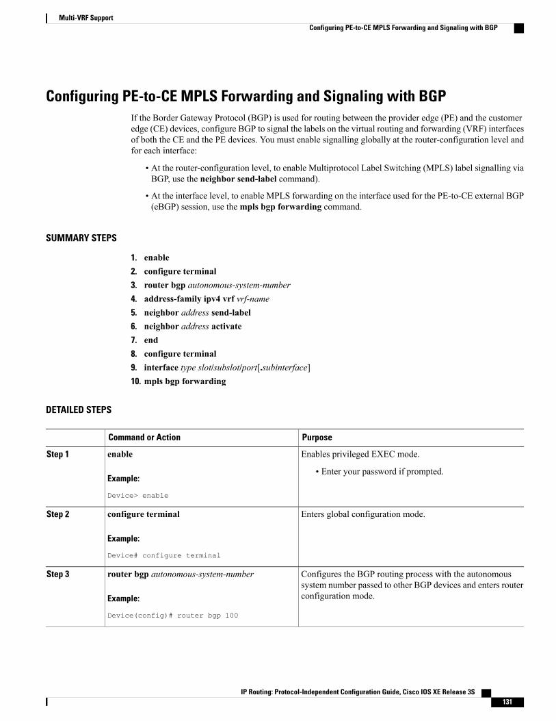
Configuring PE-to-CE MPLS Forwarding and Signaling with BGPIf the Border Gateway Protocol (BGP) is used for routing between the provider edge (PE) and the customeredge (CE) devices, configure BGP to signal the labels on the virtual routing and forwarding (VRF) interfacesof both the CE and the PE devices. You must enable signalling globally at the router-configuration level andfor each interface:
• At the router-configuration level, to enable Multiprotocol Label Switching (MPLS) label signalling viaBGP, use the neighbor send-label command).
• At the interface level, to enable MPLS forwarding on the interface used for the PE-to-CE external BGP(eBGP) session, use thempls bgp forwarding command.
SUMMARY STEPS
1. enable2. configure terminal3. router bgp autonomous-system-number4. address-family ipv4 vrf vrf-name5. neighbor address send-label6. neighbor address activate7. end8. configure terminal9. interface type slot/subslot/port[.subinterface]10. mpls bgp forwarding
DETAILED STEPS
PurposeCommand or Action
Enables privileged EXEC mode.enableStep 1
Example:
Device> enable
• Enter your password if prompted.
Enters global configuration mode.configure terminal
Example:
Device# configure terminal
Step 2
Configures the BGP routing process with the autonomoussystem number passed to other BGP devices and enters routerconfiguration mode.
router bgp autonomous-system-number
Example:
Device(config)# router bgp 100
Step 3
IP Routing: Protocol-Independent Configuration Guide, Cisco IOS XE Release 3S 131
Multi-VRF SupportConfiguring PE-to-CE MPLS Forwarding and Signaling with BGP
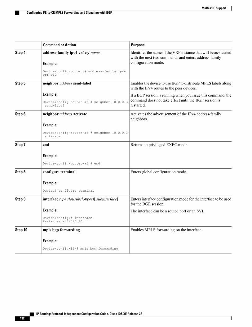
PurposeCommand or Action
Identifies the name of the VRF instance that will be associatedwith the next two commands and enters address familyconfiguration mode.
address-family ipv4 vrf vrf-name
Example:
Device(config-router)# address-family ipv4vrf v12
Step 4
Enables the device to use BGP to distributeMPLS labels alongwith the IPv4 routes to the peer devices.
neighbor address send-label
Example:
Device(config-router-af)# neighbor 10.0.0.3send-label
Step 5
If a BGP session is running when you issue this command, thecommand does not take effect until the BGP session isrestarted.
Activates the advertisement of the IPv4 address-familyneighbors.
neighbor address activate
Example:
Device(config-router-af)# neighbor 10.0.0.3activate
Step 6
Returns to privileged EXEC mode.end
Example:
Device(config-router-af)# end
Step 7
Enters global configuration mode.configure terminal
Example:
Device# configure terminal
Step 8
Enters interface configurationmode for the interface to be usedfor the BGP session.
interface type slot/subslot/port[.subinterface]
Example:
Device(config)# interfacefastethernet3/0/0.10
Step 9
The interface can be a routed port or an SVI.
Enables MPLS forwarding on the interface.mpls bgp forwarding
Example:
Device(config-if)# mpls bgp forwarding
Step 10
IP Routing: Protocol-Independent Configuration Guide, Cisco IOS XE Release 3S132
Multi-VRF SupportConfiguring PE-to-CE MPLS Forwarding and Signaling with BGP

Configuring a Routing Protocol Other than BGPYou can use the Routing Information Protocol (RIP), Enhanced Interior Gateway Routing Protocol (EIGRP),Open Shortest Path First (OSPF), or static routing. This configuration uses OSPF, but the process is the samefor other protocols.
If you use OSPF as the routing protocol between the provider edge (PE) and the customer edge (CE) devices,issue the capability vrf-lite command in router configuration mode.
If RIP EIGRP, OSPF or static routing is used, the Label Distribution Protocol (LDP) must be used tosignal labels.
The Multi-VRF Support feature is not supported by Interior Gateway Routing Protocol (IGRP) orIntermediate System-to-Intermediate System (IS-IS).
Multicast cannot be configured on the same Layer 3 interface as the Multi-VRF Support feature isconfigured.
Note
SUMMARY STEPS
1. enable2. configure terminal3. router ospf process-id [vrf vpn-name]4. log-adjacency-changes5. redistribute bgp autonomous-system-number subnets6. network ip-address subnet-mask area area-id7. end8. show ip ospf
DETAILED STEPS
PurposeCommand or Action
Enables privileged EXEC mode.enableStep 1
Example:
Device> enable
• Enter your password if prompted.
Enters global configuration mode.configure terminal
Example:
Device# configure terminal
Step 2
IP Routing: Protocol-Independent Configuration Guide, Cisco IOS XE Release 3S 133
Multi-VRF SupportConfiguring a Routing Protocol Other than BGP
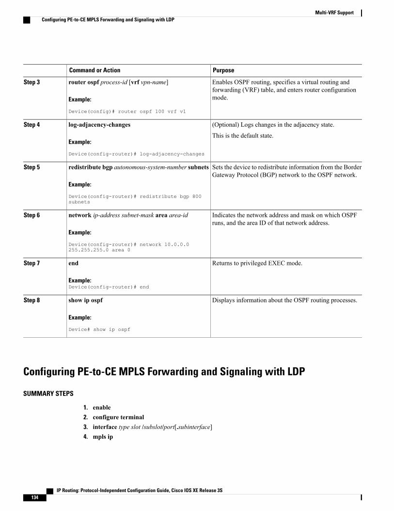
PurposeCommand or Action
Enables OSPF routing, specifies a virtual routing andforwarding (VRF) table, and enters router configurationmode.
router ospf process-id [vrf vpn-name]
Example:
Device(config)# router ospf 100 vrf v1
Step 3
(Optional) Logs changes in the adjacency state.log-adjacency-changesStep 4
Example:
Device(config-router)# log-adjacency-changes
This is the default state.
Sets the device to redistribute information from the BorderGateway Protocol (BGP) network to the OSPF network.
redistribute bgp autonomous-system-number subnets
Example:
Device(config-router)# redistribute bgp 800subnets
Step 5
Indicates the network address and mask on which OSPFruns, and the area ID of that network address.
network ip-address subnet-mask area area-id
Example:
Device(config-router)# network 10.0.0.0255.255.255.0 area 0
Step 6
Returns to privileged EXEC mode.end
Example:Device(config-router)# end
Step 7
Displays information about the OSPF routing processes.show ip ospf
Example:
Device# show ip ospf
Step 8
Configuring PE-to-CE MPLS Forwarding and Signaling with LDP
SUMMARY STEPS
1. enable2. configure terminal3. interface type slot /subslot/port[.subinterface]4. mpls ip
IP Routing: Protocol-Independent Configuration Guide, Cisco IOS XE Release 3S134
Multi-VRF SupportConfiguring PE-to-CE MPLS Forwarding and Signaling with LDP

DETAILED STEPS
PurposeCommand or Action
Enables privileged EXEC mode.enableStep 1
Example:
Device> enable
• Enter your password if prompted.
Enters global configuration mode.configure terminal
Example:
Device# configure terminal
Step 2
Enters interface configurationmode for the interface associatedwith the VRF. The interface can be a routed port or an SVI.
interface type slot /subslot/port[.subinterface]
Example:
Device(config)# interfacefastethernet3/0/0.10
Step 3
Enables MPLS forwarding of IPv4 packets along normallyrouted paths for this interface.
mpls ip
Example:
Device(config-if)# mpls ip
Step 4
Configuration Examples for Multi-VRF SupportThe figure below is an example of a Multi-VRF topology.
IP Routing: Protocol-Independent Configuration Guide, Cisco IOS XE Release 3S 135
Multi-VRF SupportConfiguration Examples for Multi-VRF Support
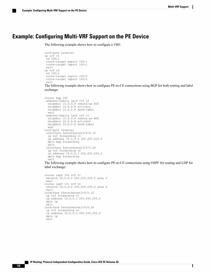
Example: Configuring Multi-VRF Support on the PE DeviceThe following example shows how to configure a VRF:
configure terminalip vrf v1rd 100:1route-target export 100:1route-target import 100:1exitip vrf v2rd 100:2route-target export 100:2route-target import 100:2exitThe following example shows how to configure PE-to-CE connections using BGP for both routing and labelexchange:
router bgp 100address-family ipv4 vrf v2neighbor 10.0.0.8 remote-as 800neighbor 10.0.0.8 activateneighbor 10.0.0.8 send-labelexitaddress-family ipv4 vrf vlneighbor 10.0.0.8 remote-as 800neighbor 10.0.0.8 activateneighbor 10.0.0.8 send-labelend
configure terminalinterface fastethernet3/0/0.10ip vrf forwarding v1ip address 10.0.0.3 255.255.255.0mpls bgp forwardingexitinterface fastethernet3/0/0.20ip vrf forwarding v2ip address 10.0.0.3 255.255.255.0mpls bgp forwardingexit
The following example shows how to configure PE-to-CE connections using OSPF for routing and LDP forlabel exchange:
router ospf 100 vrf v1network 10.0.0.0 255.255.255.0 area 0exitrouter ospf 101 vrf v2network 10.0.0.0 255.255.255.0 area 0exitinterface fastethernet3/0/0.10ip vrf forwarding v1ip address 10.0.0.3 255.255.255.0mpls ipexitinterface fastethernet3/0/0.20ip vrf forwarding v2ip address 10.0.0.3 255.255.255.0mpls ipexit
IP Routing: Protocol-Independent Configuration Guide, Cisco IOS XE Release 3S136
Multi-VRF SupportExample: Configuring Multi-VRF Support on the PE Device
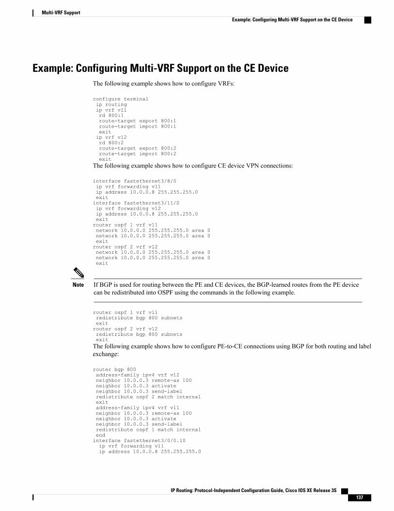
Example: Configuring Multi-VRF Support on the CE DeviceThe following example shows how to configure VRFs:
configure terminalip routingip vrf v11rd 800:1route-target export 800:1route-target import 800:1exitip vrf v12rd 800:2route-target export 800:2route-target import 800:2exit
The following example shows how to configure CE device VPN connections:
interface fastethernet3/8/0ip vrf forwarding v11ip address 10.0.0.8 255.255.255.0exitinterface fastethernet3/11/0ip vrf forwarding v12ip address 10.0.0.8 255.255.255.0exitrouter ospf 1 vrf v11network 10.0.0.0 255.255.255.0 area 0network 10.0.0.0 255.255.255.0 area 0exitrouter ospf 2 vrf v12network 10.0.0.0 255.255.255.0 area 0network 10.0.0.0 255.255.255.0 area 0exit
If BGP is used for routing between the PE and CE devices, the BGP-learned routes from the PE devicecan be redistributed into OSPF using the commands in the following example.
Note
router ospf 1 vrf v11redistribute bgp 800 subnetsexitrouter ospf 2 vrf v12redistribute bgp 800 subnetsexitThe following example shows how to configure PE-to-CE connections using BGP for both routing and labelexchange:
router bgp 800address-family ipv4 vrf v12neighbor 10.0.0.3 remote-as 100neighbor 10.0.0.3 activateneighbor 10.0.0.3 send-labelredistribute ospf 2 match internalexitaddress-family ipv4 vrf vl1neighbor 10.0.0.3 remote-as 100neighbor 10.0.0.3 activateneighbor 10.0.0.3 send-labelredistribute ospf 1 match internalendinterface fastethernet3/0/0.10ip vrf forwarding v11ip address 10.0.0.8 255.255.255.0
IP Routing: Protocol-Independent Configuration Guide, Cisco IOS XE Release 3S 137
Multi-VRF SupportExample: Configuring Multi-VRF Support on the CE Device
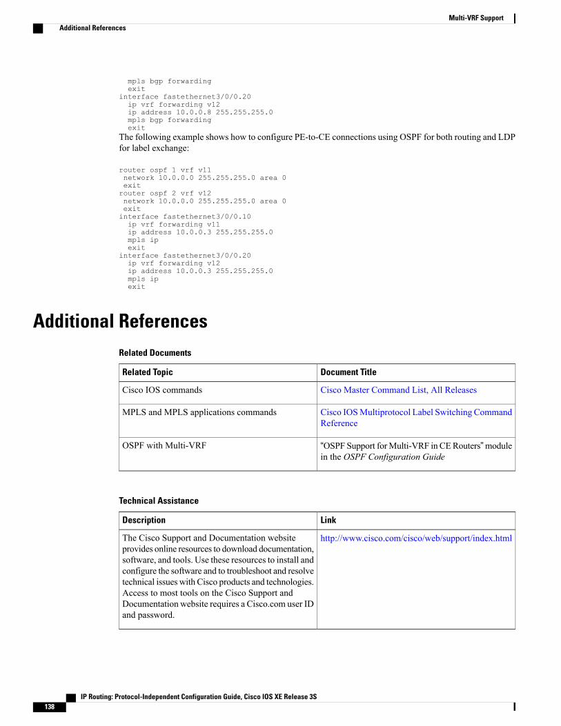
mpls bgp forwardingexit
interface fastethernet3/0/0.20ip vrf forwarding v12ip address 10.0.0.8 255.255.255.0mpls bgp forwardingexit
The following example shows how to configure PE-to-CE connections using OSPF for both routing and LDPfor label exchange:
router ospf 1 vrf v11network 10.0.0.0 255.255.255.0 area 0exitrouter ospf 2 vrf v12network 10.0.0.0 255.255.255.0 area 0exitinterface fastethernet3/0/0.10ip vrf forwarding v11ip address 10.0.0.3 255.255.255.0mpls ipexit
interface fastethernet3/0/0.20ip vrf forwarding v12ip address 10.0.0.3 255.255.255.0mpls ipexit
Additional ReferencesRelated Documents
Document TitleRelated Topic
Cisco Master Command List, All ReleasesCisco IOS commands
Cisco IOSMultiprotocol Label Switching CommandReference
MPLS and MPLS applications commands
“OSPF Support forMulti-VRF in CERouters”modulein the OSPF Configuration Guide
OSPF with Multi-VRF
Technical Assistance
LinkDescription
http://www.cisco.com/cisco/web/support/index.htmlThe Cisco Support and Documentation websiteprovides online resources to download documentation,software, and tools. Use these resources to install andconfigure the software and to troubleshoot and resolvetechnical issues with Cisco products and technologies.Access to most tools on the Cisco Support andDocumentation website requires a Cisco.com user IDand password.
IP Routing: Protocol-Independent Configuration Guide, Cisco IOS XE Release 3S138
Multi-VRF SupportAdditional References
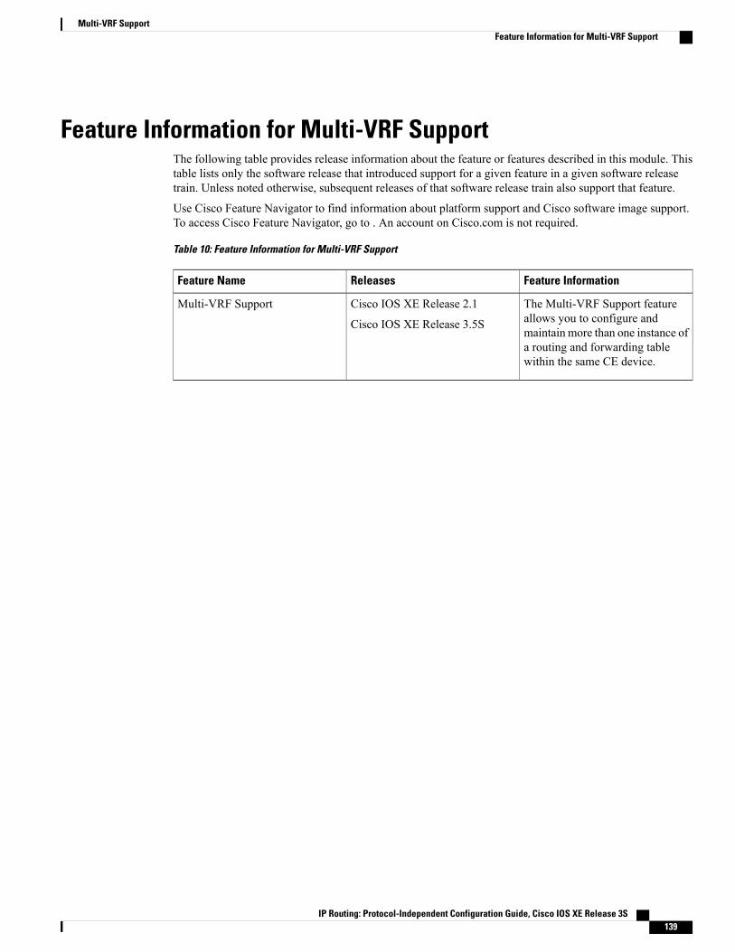
Feature Information for Multi-VRF SupportThe following table provides release information about the feature or features described in this module. Thistable lists only the software release that introduced support for a given feature in a given software releasetrain. Unless noted otherwise, subsequent releases of that software release train also support that feature.
Use Cisco Feature Navigator to find information about platform support and Cisco software image support.To access Cisco Feature Navigator, go to . An account on Cisco.com is not required.
Table 10: Feature Information for Multi-VRF Support
Feature InformationReleasesFeature Name
The Multi-VRF Support featureallows you to configure andmaintain more than one instance ofa routing and forwarding tablewithin the same CE device.
Cisco IOS XE Release 2.1
Cisco IOS XE Release 3.5S
Multi-VRF Support
IP Routing: Protocol-Independent Configuration Guide, Cisco IOS XE Release 3S 139
Multi-VRF SupportFeature Information for Multi-VRF Support

IP Routing: Protocol-Independent Configuration Guide, Cisco IOS XE Release 3S140
Multi-VRF SupportFeature Information for Multi-VRF Support
C H A P T E R 11Default Passive Interfaces
The Default Passive Interfaces feature simplifies the configuration of distribution devices by allowing allinterfaces to be set as passive by default. In ISPs and large enterprise networks, many distribution deviceshave more than 200 interfaces. Obtaining routing information from these interfaces requires configurationof the routing protocol on all interfaces and manual configuration of the passive-interface command oninterfaces where adjacencies were not desired.
• Finding Feature Information, page 141
• Information About Default Passive Interfaces, page 142
• How to Configure Default Passive Interfaces, page 143
• Configuration Examples for Default Passive Interfaces, page 144
• Additional References, page 146
• Feature Information for Default Passive Interfaces, page 146
Finding Feature InformationYour software release may not support all the features documented in this module. For the latest caveats andfeature information, see Bug Search Tool and the release notes for your platform and software release. Tofind information about the features documented in this module, and to see a list of the releases in which eachfeature is supported, see the feature information table.
Use Cisco Feature Navigator to find information about platform support and Cisco software image support.To access Cisco Feature Navigator, go to www.cisco.com/go/cfn. An account on Cisco.com is not required.
IP Routing: Protocol-Independent Configuration Guide, Cisco IOS XE Release 3S 141

Information About Default Passive Interfaces
Default Passive InterfacesIn large enterprise networks, many distribution devices havemore than 200 interfaces. Before the introductionof the Default Passive Interfaces feature, routing information could be obtained from these interfaces in theseways:
• Configure a routing protocol such as Open Shortest Path First (OSPF) on the backbone interfaces andredistribute connected interfaces.
• Configure a routing protocol on all interfaces and manually set most of them as passive.
Network operators might not always be able to summarize type 5 link-state advertisements (LSAs) at thedevice level where redistribution occurs, as in the first possibility. Thus, a large number of type 5 LSAs canbe flooded over the domain.
In the second possibility, large type 1 LSAsmight be flooded over the domain. The Area Border Router (ABR)creates type 3 LSAs, one for each type 1 LSA, and floods them to the backbone. You can, however, haveunique summarization at the ABR level, which injects only one summary route into the backbone, therebyreducing the processing overhead.
Before the introduction of the Default Passive Interfaces feature, you could configure the routing protocol onall interfaces and manually set the passive-interface router configuration command on interfaces whereadjacencies were not desired. But in some networks, this solution meant configuring 200 or more passiveinterfaces. The Default Passive Interfaces feature solved this problem by allowing all interfaces to be set aspassive by default. You can set all interfaces as passive by default by using the passive-interface defaultcommand and then configure individual interfaces where adjacencies are desired using the no passive-interfacecommand.
The Default Passive Interfaces feature simplifies the configuration of distribution devices and allows thenetwork administrator to obtain routing information from interfaces in ISPs and large enterprise networks.
Preventing Routing Updates Through an InterfaceTo prevent other devices on a local network from learning about routes dynamically, you can keep routingupdate messages from being sent through a device interface. This feature applies to all IP-based routingprotocols except the Border Gateway Protocol (BGP).
Open Shortest Path First (OSPF) and Intermediate System to Intermediate System (IS-IS) behave somewhatdifferently. In OSPF, the interface address that you specify as passive appears as a stub network in the OSPFdomain. OSPF routing information is neither sent nor received through the specified device interface. In IS-IS,the specified IP addresses are advertised without actually running IS-IS on those interfaces.
To prevent routing updates through a specified interface, use the passive-interface type number commandin router configuration mode.
IP Routing: Protocol-Independent Configuration Guide, Cisco IOS XE Release 3S142
Default Passive InterfacesInformation About Default Passive Interfaces

How to Configure Default Passive Interfaces
Configuring Default Passive InterfacesPerform this task to set all interfaces on a device, in an Enhanced Interior Gateway Routing Protocol (EIGRP)environment, as passive by default, and then activate only those interfaces where adjacencies are desired.
SUMMARY STEPS
1. enable2. configure terminal3. router eigrp {autonomous-system-number | virtual-instance-number}4. passive-interface [default] [type number]5. no passive-interface [default] [type number]6. network network-address [options]7. end8. show ip eigrp interfaces9. show ip interface
DETAILED STEPS
PurposeCommand or Action
Enables privileged EXEC mode.enableStep 1
Example:
Device> enable
• Enter your password if prompted.
Enters global configuration mode.configure terminal
Example:
Device# configure terminal
Step 2
Configures an EIGRP process and enters router configurationmode.
router eigrp {autonomous-system-number |virtual-instance-number}
Step 3
Example:
Device(config)# router eigrp 1
• autonomous-system-number—Autonomous systemnumberthat identifies the services to the other EIGRPaddress-family devices. It is also used to tag routinginformation. The range is 1 to 65535.
• virtual-instance-number—EIGRP virtual instance name.This namemust be unique among all address-family routerprocesses on a single device, but need not be uniqueamong devices
IP Routing: Protocol-Independent Configuration Guide, Cisco IOS XE Release 3S 143
Default Passive InterfacesHow to Configure Default Passive Interfaces

PurposeCommand or Action
Sets all interfaces as passive by default.passive-interface [default] [type number]
Example:
Device(config-router)# passive-interfacedefault
Step 4
Activates only those interfaces that need adjacencies.no passive-interface [default] [type number]
Example:
Device(config-router)# no passive-interfacegigabitethernet 0/0/0
Step 5
Specifies the list of networks to be advertised by routingprotocols.
network network-address [options]
Example:
Device(config-router)# network 192.0.2.0
Step 6
Exits router configurationmode and returns to privileged EXECmode.
end
Example:
Device(config-router)# end
Step 7
Verifies whether interfaces on your network have been set topassive.
show ip eigrp interfaces
Example:Device# show ip eigrp interfaces
Step 8
Verifies whether interfaces you enabled are active.show ip interface
Example:Device# show ip interface
Step 9
Configuration Examples for Default Passive Interfaces
Examples: Passive Interfaces Configuration for OSPFIn Open Shortest Path First (OSPF), hello packets are not sent on an interface that is specified as passive.Hence, the device is not able to discover any neighbors, and none of the OSPF neighbors are able to see thedevice on that network. In effect, this interface appears as a stub network to the OSPF domain. Thisconfiguration is useful if you want to import routes associated with a connected network into the OSPF domainwithout any OSPF activity on that interface.
IP Routing: Protocol-Independent Configuration Guide, Cisco IOS XE Release 3S144
Default Passive InterfacesConfiguration Examples for Default Passive Interfaces

The passive-interface router configuration command is typically used when the wildcard specification onthe network router configuration command configures more interfaces than is desirable. The followingconfiguration causes OSPF to run on all subnets of 172.18.0.0:
Device(config)# interface GigabitEthernet 0/0/0Device(config-if)# ip address 172.18.1.1 255.255.255.0Device(config-if)# exitDevice(config)# interface GigabitEthernet 1/0/0Device(config-if)# ip address 172.18.2.1 255.255.255.0Device(config-if)# exitDevice(config)# interface GigabitEthernet 2/0/0Device(config-if)# ip address 172.18.3.1 255.255.255.0Device(config-if)# exitDevice(config)# router ospf 1Device(config-router)# network 172.18.0.0 0.0.255.255 area 0Device(config-router)# exitIf you do not want OSPF to run on 172.18.3.0, enter the following commands:
Device(config)# router ospf 1Device(config-router)# network 172.18.0.0 0.0.255.255 area 0Device(config-router)# no passive-interface GigabitEthernet 2/0/0Device(config-router)# exit
Example: Default Passive Interfaces Configuration for OSPFThe following example configures the network interfaces, sets all interfaces that are running Open ShortestPath First (OSPF) as passive, and then enables serial interface 0/0/0:
Device(config)# interface GigabitEthernet 0/0/0Device(config-if)# ip address 172.19.64.38 255.255.255.0 secondaryDevice(config-if)# ip address 172.19.232.70 255.255.255.240Device(config-if)# no ip directed-broadcastDevice(config-if)# exitDevice(config)# interface Serial 0/0/0Device(config-if)# ip address 172.24.101.14 255.255.255.252Device(config-if)# no ip directed-broadcastDevice(config-if)# no ip mroute-cacheDevice(config-if)# exitDevice(config)# interface TokenRing 0/0/0Device(config-if)# ip address 172.20.10.4 255.255.255.0Device(config-if)# no ip directed-broadcastDevice(config-if)# no ip mroute-cacheDevice(config-if)# ring-speed 16Device(config-if)# exitDevice(config)# router ospf 1Device(config-router)# passive-interface defaultDevice(config-router)# no passive-interface Serial 0/0/0Device(config-router)# network 172.16.10.0 0.0.0.255 area 0Device(config-router)# network 172.19.232.0 0.0.0.255 area 4Device(config-router)# network 172.24.101.0 0.0.0.255 area 4Device(config-router)# end
IP Routing: Protocol-Independent Configuration Guide, Cisco IOS XE Release 3S 145
Default Passive InterfacesExample: Default Passive Interfaces Configuration for OSPF

Additional ReferencesRelated Documents
Document TitleRelated Topic
Cisco IOS Master Command List, All ReleasesCisco IOS commands
Cisco IOS IP Routing: Protocol-IndependentCommand Reference
IP routing protocol-independent commands
Technical Assistance
LinkDescription
http://www.cisco.com/cisco/web/support/index.htmlThe Cisco Support and Documentation websiteprovides online resources to download documentation,software, and tools. Use these resources to install andconfigure the software and to troubleshoot and resolvetechnical issues with Cisco products and technologies.Access to most tools on the Cisco Support andDocumentation website requires a Cisco.com user IDand password.
Feature Information for Default Passive InterfacesThe following table provides release information about the feature or features described in this module. Thistable lists only the software release that introduced support for a given feature in a given software releasetrain. Unless noted otherwise, subsequent releases of that software release train also support that feature.
Use Cisco Feature Navigator to find information about platform support and Cisco software image support.To access Cisco Feature Navigator, go to . An account on Cisco.com is not required.
IP Routing: Protocol-Independent Configuration Guide, Cisco IOS XE Release 3S146
Default Passive InterfacesAdditional References

Table 11: Feature Information for Default Passive Interfaces
Feature InformationReleasesFeature Name
In ISP and large enterprisenetworks, many of the distributiondevices have more than 200interfaces. Obtaining routinginformation from these interfacesrequired configuration of therouting protocol on all interfacesand manual configuration of thepassive-interface command on theinterfaces where adjacencywas notdesired. The Default PassiveInterface feature simplifies theconfiguration of distributiondevices by allowing all interfacesto be set as passive by default usinga single passive-interface defaultcommand, and then by configuringindividual interfaces whereadjacencies are desired using theno passive-interface command.
Default Passive Interfaces
IP Routing: Protocol-Independent Configuration Guide, Cisco IOS XE Release 3S 147
Default Passive InterfacesFeature Information for Default Passive Interfaces

IP Routing: Protocol-Independent Configuration Guide, Cisco IOS XE Release 3S148
Default Passive InterfacesFeature Information for Default Passive Interfaces

C H A P T E R 12Policy-Based Routing
The Policy-Based Routing feature is a process whereby a device puts packets through a route map beforerouting the packets. The route map determines which packets are routed next to which device. Policy-basedrouting is a more flexible mechanism for routing packets than destination routing.
• Finding Feature Information, page 149
• Prerequisites for Policy-Based Routing, page 149
• Information About Policy-Based Routing, page 150
• How to Configure Policy-Based Routing, page 151
• Configuration Examples for Policy-Based Routing, page 153
• Additional References, page 153
• Feature Information for Policy-Based Routing, page 154
Finding Feature InformationYour software release may not support all the features documented in this module. For the latest caveats andfeature information, see Bug Search Tool and the release notes for your platform and software release. Tofind information about the features documented in this module, and to see a list of the releases in which eachfeature is supported, see the feature information table.
Use Cisco Feature Navigator to find information about platform support and Cisco software image support.To access Cisco Feature Navigator, go to www.cisco.com/go/cfn. An account on Cisco.com is not required.
Prerequisites for Policy-Based RoutingFor Policy-Based Routing, IPBase is a minimum licensing requirement.
IP Routing: Protocol-Independent Configuration Guide, Cisco IOS XE Release 3S 149

Information About Policy-Based Routing
Policy-Based RoutingPolicy-based routing is a process whereby the device puts packets through a route map before routing them.The route map determines which packets are routed to which device next. You might enable policy-basedrouting if you want certain packets to be routed some way other than the obvious shortest path. Possibleapplications for policy-based routing are to provide equal access, protocol-sensitive routing, source-sensitiverouting, routing based on interactive versus batch traffic, and routing based on dedicated links. Policy-basedrouting is a more flexible mechanism for routing packets than destination routing.
To enable policy-based routing, you must identify which route map to use for policy-based routing and createthe route map. The route map itself specifies the match criteria and the resulting action if all of the matchclauses are met.
To enable policy-based routing on an interface, indicate which route map the device should use by using theip policy route-map map-tag command in interface configuration mode. A packet arriving on the specifiedinterface is subject to policy-based routing except when its destination IP address is the same as the IP addressof the device’s interface. This ip policy route-map command disables fast switching of all packets arrivingon this interface.
To define the route map to be used for policy-based routing, use the route-map map-tag [permit | deny][sequence-number] global configuration command.
To define the criteria by which packets are examined to learn if they will be policy-based routed, use eitherthematch length minimum-length maximum-length command or thematch ip address {access-list-number| access-list-name} [access-list-number | access-list-name] command or both in route map configuration mode.No match clause in the route map indicates all packets.
To display the cache entries in the policy route cache, use the show ip cache policy command.
Mediatrace will show statistics of incorrect interfaces with policy-based routing (PBR) if the PBR doesnot interact with CEF or Resource Reservation Protocol (RSVP). Hence configure PBR to interact withCEF or RSVP directly so that mediatrace collects statistics only on tunnel interfaces and not physicalinterfaces.
Note
IP Routing: Protocol-Independent Configuration Guide, Cisco IOS XE Release 3S150
Policy-Based RoutingInformation About Policy-Based Routing

How to Configure Policy-Based Routing
Configuring Policy-Based Routing
SUMMARY STEPS
1. enable2. configure terminal3. interface type number4. ip policy route-map map-tag5. exit6. route-map map-tag [permit | deny] [sequence-number]7. Enter one or both of the following commands:
• match length
• match ip address
8. set ip next-hop {ip-address[...ip-address] | dynamic dhcp | encapsulate l3vpn profile-name | peer-address| recursive [global | vrf vrf-name] ip-address | verify-availability [ip-address sequence tracktrack-object-number]}
9. end
DETAILED STEPS
PurposeCommand or Action
Enables privileged EXEC mode.enableStep 1
Example:
Device> enable
• Enter your password if prompted.
Enters global configuration mode.configure terminal
Example:
Device# configure terminal
Step 2
Configures an interface type and enters interface configuration mode.interface type number
Example:
Device(config)# interface gigabitethernet1/0/0
Step 3
IP Routing: Protocol-Independent Configuration Guide, Cisco IOS XE Release 3S 151
Policy-Based RoutingHow to Configure Policy-Based Routing
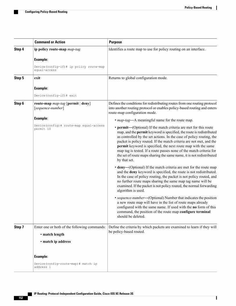
PurposeCommand or Action
Identifies a route map to use for policy routing on an interface.ip policy route-map map-tag
Example:
Device(config-if)# ip policy route-mapequal-access
Step 4
Returns to global configuration mode.exit
Example:
Device(config-if)# exit
Step 5
Defines the conditions for redistributing routes from one routing protocolinto another routing protocol or enables policy-based routing and entersroute-map configuration mode.
route-map map-tag [permit | deny][sequence-number]
Example:
Device(config)# route-map equal-accesspermit 10
Step 6
• map-tag—A meaningful name for the route map.
• permit—(Optional) If the match criteria are met for this routemap, and the permit keyword is specified, the route is redistributedas controlled by the set actions. In the case of policy routing, thepacket is policy routed. If the match criteria are not met, and thepermit keyword is specified, the next route map with the samemap tag is tested. If a route passes none of the match criteria forthe set of route maps sharing the same name, it is not redistributedby that set.
• deny—(Optional) If the match criteria are met for the route mapand the deny keyword is specified, the route is not redistributed.In the case of policy routing, the packet is not policy routed, andno further route maps sharing the same map tag name will beexamined. If the packet is not policy routed, the normal forwardingalgorithm is used.
• sequence-number—(Optional) Number that indicates the positiona new route map will have in the list of route maps alreadyconfigured with the same name. If used with the no form of thiscommand, the position of the route map configure terminalshould be deleted.
Define the criteria by which packets are examined to learn if they willbe policy-based routed.
Enter one or both of the following commands:Step 7
• match length
• match ip address
Example:
Device(config-route-map)# match ipaddress 1
IP Routing: Protocol-Independent Configuration Guide, Cisco IOS XE Release 3S152
Policy-Based RoutingConfiguring Policy-Based Routing
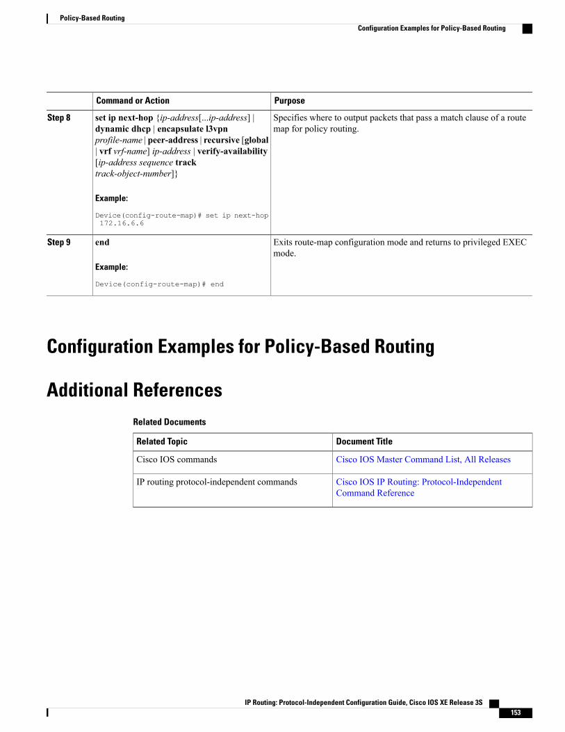
PurposeCommand or Action
Specifies where to output packets that pass a match clause of a routemap for policy routing.
set ip next-hop {ip-address[...ip-address] |dynamic dhcp | encapsulate l3vpnprofile-name | peer-address | recursive [global
Step 8
| vrf vrf-name] ip-address | verify-availability[ip-address sequence tracktrack-object-number]}
Example:
Device(config-route-map)# set ip next-hop172.16.6.6
Exits route-map configuration mode and returns to privileged EXECmode.
end
Example:
Device(config-route-map)# end
Step 9
Configuration Examples for Policy-Based Routing
Additional ReferencesRelated Documents
Document TitleRelated Topic
Cisco IOS Master Command List, All ReleasesCisco IOS commands
Cisco IOS IP Routing: Protocol-IndependentCommand Reference
IP routing protocol-independent commands
IP Routing: Protocol-Independent Configuration Guide, Cisco IOS XE Release 3S 153
Policy-Based RoutingConfiguration Examples for Policy-Based Routing
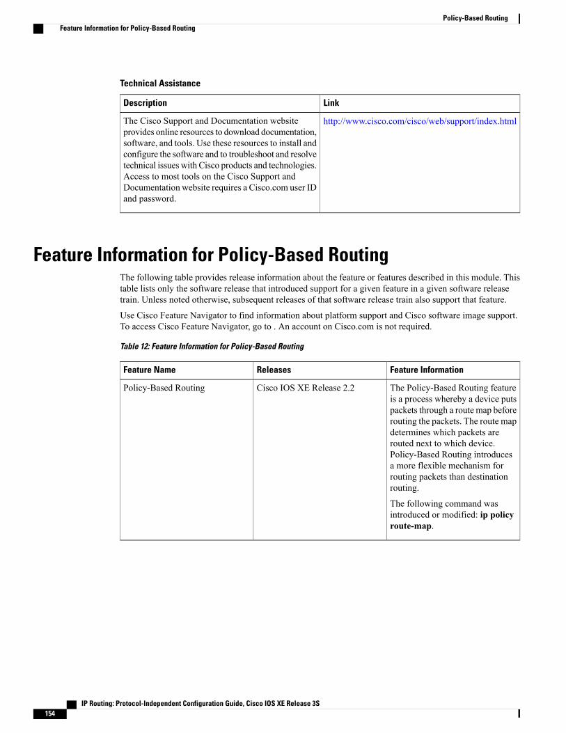
Technical Assistance
LinkDescription
http://www.cisco.com/cisco/web/support/index.htmlThe Cisco Support and Documentation websiteprovides online resources to download documentation,software, and tools. Use these resources to install andconfigure the software and to troubleshoot and resolvetechnical issues with Cisco products and technologies.Access to most tools on the Cisco Support andDocumentation website requires a Cisco.com user IDand password.
Feature Information for Policy-Based RoutingThe following table provides release information about the feature or features described in this module. Thistable lists only the software release that introduced support for a given feature in a given software releasetrain. Unless noted otherwise, subsequent releases of that software release train also support that feature.
Use Cisco Feature Navigator to find information about platform support and Cisco software image support.To access Cisco Feature Navigator, go to . An account on Cisco.com is not required.
Table 12: Feature Information for Policy-Based Routing
Feature InformationReleasesFeature Name
The Policy-Based Routing featureis a process whereby a device putspackets through a route map beforerouting the packets. The route mapdetermines which packets arerouted next to which device.Policy-Based Routing introducesa more flexible mechanism forrouting packets than destinationrouting.
The following command wasintroduced or modified: ip policyroute-map.
Cisco IOS XE Release 2.2Policy-Based Routing
IP Routing: Protocol-Independent Configuration Guide, Cisco IOS XE Release 3S154
Policy-Based RoutingFeature Information for Policy-Based Routing
C H A P T E R 13SGT Based PBR
The SGT Based PBR feature supports classification of packets based on Security Group for grouping thetraffic into roles to match the defined policies in Policy-Based Routing (PBR).
• Finding Feature Information, page 155
• Restrictions for SGT Based PBR, page 155
• Information About SGT Based PBR, page 156
• How to Configure SGT Based PBR, page 156
• Configuration Examples for SGT Based PBR, page 160
• Additional References for SGT Based PBR, page 160
• Feature Information for SGT Based PBR, page 161
Finding Feature InformationYour software release may not support all the features documented in this module. For the latest caveats andfeature information, see Bug Search Tool and the release notes for your platform and software release. Tofind information about the features documented in this module, and to see a list of the releases in which eachfeature is supported, see the feature information table.
Use Cisco Feature Navigator to find information about platform support and Cisco software image support.To access Cisco Feature Navigator, go to www.cisco.com/go/cfn. An account on Cisco.com is not required.
Restrictions for SGT Based PBR• SGTBased PBR feature supports policy configuration using number based tagging and does not supportname based tagging.
• SGT Based PBR feature is not supported for IPV6 traffic on IOS XE.
• Dynamic route-map overrides static route-map when both are associated with the same interface. Awarning message is issued during an override. The static route-map is enabled when the dynamicroute-map is deleted.
IP Routing: Protocol-Independent Configuration Guide, Cisco IOS XE Release 3S 155
• We recommend disassociating the route-map before it is deleted. You cannot configure static PBR ifthe route-map is deleted before disassociating it from the interface.
Information About SGT Based PBR
Cisco TrustSecCisco TrustSec assigns a Security Group Tag, (SGT) to the user’s or device’s traffic at ingress and applies theaccess policy based on the assigned tag. SGT Based PBR feature allows you to configure PBR based onSecurity Group classification enabling you to group users or devices into a role to match the defined policies.
SGT Based PBRSecurity Group classification includes both Source and Destination Group, which is specified by source SGTand DGT. SGT Based PBR feature provides the PBR route-map match clause for SGT/DGT based packetclassification. SGT Based PBR feature supports configuration of unlimited number of tags, but it isrecommended to configure the tags based on memory available in the platform. SGT Based PBR supportsVPN routing and forwarding (VRF) selection match criteria which can be used for policy based classificationand forwarding of Virtual Private Network (VPN) traffic.
How to Configure SGT Based PBR
Configuring Match Security Group Tag
SUMMARY STEPS
1. enable2. configure terminal3. route-map map-tag4. match security-group source tag sgt-number5. set ip next-hop ip-address6. match security-group destination tag sgt-number7. set ip next-hop ip-address8. end
DETAILED STEPS
PurposeCommand or Action
Enables privileged EXEC mode.enableStep 1
IP Routing: Protocol-Independent Configuration Guide, Cisco IOS XE Release 3S156
SGT Based PBRInformation About SGT Based PBR
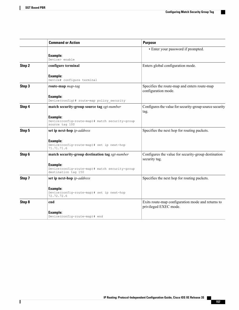
PurposeCommand or Action
Example:Device> enable
• Enter your password if prompted.
Enters global configuration mode.configure terminal
Example:Device# configure terminal
Step 2
Specifies the route-map and enters route-mapconfiguration mode.
route-map map-tag
Example:Device(config)# route-map policy_security
Step 3
Configures the value for security-group source securitytag.
match security-group source tag sgt-number
Example:Device(config-route-map)# match security-groupsource tag 100
Step 4
Specifies the next hop for routing packets.set ip next-hop ip-address
Example:Device(config-route-map)# set ip next-hop71.71.71.6
Step 5
Configures the value for security-group destinationsecurity tag.
match security-group destination tag sgt-number
Example:Device(config-route-map)# match security-groupdestination tag 150
Step 6
Specifies the next hop for routing packets.set ip next-hop ip-address
Example:Device(config-route-map)# set ip next-hop72.72.72.6
Step 7
Exits route-map configuration mode and returns toprivileged EXEC mode.
end
Example:Device(config-route-map)# end
Step 8
IP Routing: Protocol-Independent Configuration Guide, Cisco IOS XE Release 3S 157
SGT Based PBRConfiguring Match Security Group Tag

Assigning Route-Map to an Interface
SUMMARY STEPS
1. enable2. configure terminal3. interface typeslot/ subslot/ port[. subinterface-number]4. ip policy route-map map-tag
DETAILED STEPS
PurposeCommand or Action
Enables privileged EXEC mode.enableStep 1
Example:Device> enable
• Enter your password if prompted.
Enters global configuration mode.configure terminal
Example:Device# configure terminal
Step 2
Specifies the interface information and enters interfaceconfiguration mode.
interface typeslot/ subslot/ port[. subinterface-number]
Example:Device(config)#interface gigabitEthernet0/0/0
Step 3
Assigns the route-map configured in the previous taskto the interface.
ip policy route-map map-tag
Example:Device(config-if)#ip policy route-mappolicy_security
Step 4
Displaying and Verifying SGT Based PBR Configuration
SUMMARY STEPS
1. enable2. show ip policy3. show route-map map-tag4. show route-map dynamic
IP Routing: Protocol-Independent Configuration Guide, Cisco IOS XE Release 3S158
SGT Based PBRAssigning Route-Map to an Interface

DETAILED STEPS
Step 1 enable
Example:Device> enableEnables privileged EXEC mode.
• Enter your password if prompted.
Step 2 show ip policy
Example:Device# show ip policy
Interface Route mapGi0/0/1.77 testDisplays IP policy information.
Step 3 show route-map map-tag
Example:Device# show route-map test
route-map test, permit, sequence 10Match clauses:security-group source tag 100 111
Set clauses:ip next-hop 71.71.71.6
Policy routing matches: 0 packets, 0 bytesroute-map test, permit, sequence 20Match clauses:security-group destination tag 200 222
Set clauses:ip next-hop 72.72.72.6
Policy routing matches: 0 packets, 0 bytesDisplays route-map configuration.
Step 4 show route-map dynamic
Example:Device# show route-map dynamic
route-map AAA-02/11/15-12:32:52.955-1-test, permit, sequence 0, identifier 2818572289Match clauses:
Security-group source tag 100 300Set clauses:ip next-hop 3.3.3.2Nexthop tracking current: 3.3.3.23.3.3.2, fib_nh:7FDE41661370,oce:7FDE4C540AD0,status:1
Policy routing matches: 1012 packets, 83458 bytesCurrent active dynamic routemaps = 1Displays information about dynamic PBR route-map.
IP Routing: Protocol-Independent Configuration Guide, Cisco IOS XE Release 3S 159
SGT Based PBRDisplaying and Verifying SGT Based PBR Configuration

Configuration Examples for SGT Based PBR
Example: SGT Based PBRThe following example shows how to configure SGT Based PBR:
Example: SGT Based PBRenableconfigure terminalroute-map policy_securitymatch security-group source tag 100match security-group source tag 111set ip next-hop 71.71.71.6match security-group destination tag 200match security-group destination tag 222set ip next-hop 72.72.72.6endinterface gigabitEthernet0/0/0ip policy route-map policy_security
Additional References for SGT Based PBRRelated Documents
Document TitleRelated Topic
Cisco IOS Master Commands List, All ReleasesCisco IOS commands
Cisco IOS IP Routing Protocol IndependentCommand Reference
Cisco IOS IP Routing Protocol Independentcommands
Understanding Cisco TrustSecCisco TrustSec Overview
IP Routing: Protocol-Independent Configuration Guide, Cisco IOS XE Release 3S160
SGT Based PBRConfiguration Examples for SGT Based PBR
Technical Assistance
LinkDescription
http://www.cisco.com/cisco/web/support/index.htmlThe Cisco Support website provides extensive onlineresources, including documentation and tools fortroubleshooting and resolving technical issues withCisco products and technologies.
To receive security and technical information aboutyour products, you can subscribe to various services,such as the Product Alert Tool (accessed from FieldNotices), the Cisco Technical Services Newsletter,and Really Simple Syndication (RSS) Feeds.
Access to most tools on the Cisco Support websiterequires a Cisco.com user ID and password.
Feature Information for SGT Based PBRThe following table provides release information about the feature or features described in this module. Thistable lists only the software release that introduced support for a given feature in a given software releasetrain. Unless noted otherwise, subsequent releases of that software release train also support that feature.
Use Cisco Feature Navigator to find information about platform support and Cisco software image support.To access Cisco Feature Navigator, go to . An account on Cisco.com is not required.
IP Routing: Protocol-Independent Configuration Guide, Cisco IOS XE Release 3S 161
SGT Based PBRFeature Information for SGT Based PBR
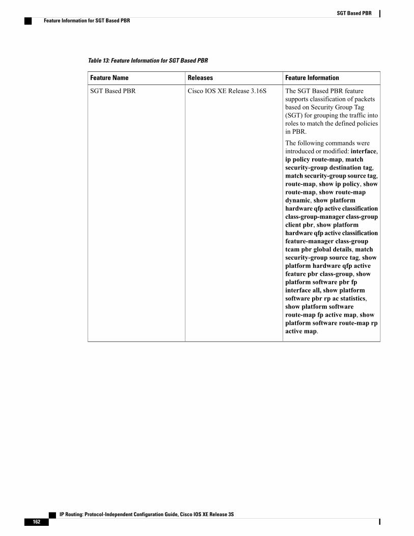
Table 13: Feature Information for SGT Based PBR
Feature InformationReleasesFeature Name
The SGT Based PBR featuresupports classification of packetsbased on Security Group Tag(SGT) for grouping the traffic intoroles to match the defined policiesin PBR.
The following commands wereintroduced or modified: interface,ip policy route-map, matchsecurity-group destination tag,match security-group source tag,route-map, show ip policy, showroute-map, show route-mapdynamic, show platformhardware qfp active classificationclass-group-manager class-groupclient pbr, show platformhardware qfp active classificationfeature-manager class-grouptcam pbr global details, matchsecurity-group source tag, showplatform hardware qfp activefeature pbr class-group, showplatform software pbr fpinterface all, show platformsoftware pbr rp ac statistics,show platform softwareroute-map fp active map, showplatform software route-map rpactive map.
Cisco IOS XE Release 3.16SSGT Based PBR
IP Routing: Protocol-Independent Configuration Guide, Cisco IOS XE Release 3S162
SGT Based PBRFeature Information for SGT Based PBR
C H A P T E R 14SGT Based QoS
The SGT Based QoS feature supports the application of security group for packet classification for usergroup and role based or device based QoS traffic routing.
• Finding Feature Information, page 163
• Prerequisites for SGT Based QoS, page 163
• Restrictions for SGT Based QoS, page 164
• Information About SGT Based QoS, page 164
• How to Configure SGT Based QoS, page 164
• Configuration Examples for SGT Based QoS, page 167
• Additional References for SGT Based QoS, page 168
• Feature Information for SGT Based QoS, page 168
Finding Feature InformationYour software release may not support all the features documented in this module. For the latest caveats andfeature information, see Bug Search Tool and the release notes for your platform and software release. Tofind information about the features documented in this module, and to see a list of the releases in which eachfeature is supported, see the feature information table.
Use Cisco Feature Navigator to find information about platform support and Cisco software image support.To access Cisco Feature Navigator, go to www.cisco.com/go/cfn. An account on Cisco.com is not required.
Prerequisites for SGT Based QoS• The user groups and devices used for SGT Based QoS configuration must be assigned to the appropriateSGT groups. SGT definition and mapping can be done through Cisco ISE or through static SGTclassification on the network device.
IP Routing: Protocol-Independent Configuration Guide, Cisco IOS XE Release 3S 163

Restrictions for SGT Based QoS• The SGT Based QoS feature does not support application prioritization within a user group.
• The SGT Based QoS feature does not support combining match application or match protocol criteriawith the match sgt criteria within a policy.
Information About SGT Based QoS
SGT Based QoSSecurity Group classification includes both Source and Destination Group, which is specified by source SGTand DGT. The SGT Based QoS feature enables prioritized allocation of bandwidth and QoS policies for adefined user group or device. The SGT Based QoS feature provides you the capability to assign multiple QoSpolicies to an application or traffic type initiated by different user groups. Each user group is defined by aunique SGT value and supports hierarchical and non-hierarchical QoS configuration. The SGT Based QoSfeature supports both user group and device based QoS service levels for SGT/DGT based packet classification.The SGT Based QoS feature supports defining of user groups based on contextual information for QoS policyprioritization.
How to Configure SGT Based QoS
Configuring User Group, Device, or Role Based QoS Policies
SUMMARY STEPS
1. enable2. configure terminal3. class-map class-map-name4. match security-group source tag sgt-number5. match security-group destination tag dgt-number6. end
DETAILED STEPS
PurposeCommand or Action
Enables privileged EXEC mode.enableStep 1
Example:Device> enable
• Enter your password if prompted.
IP Routing: Protocol-Independent Configuration Guide, Cisco IOS XE Release 3S164
SGT Based QoSRestrictions for SGT Based QoS
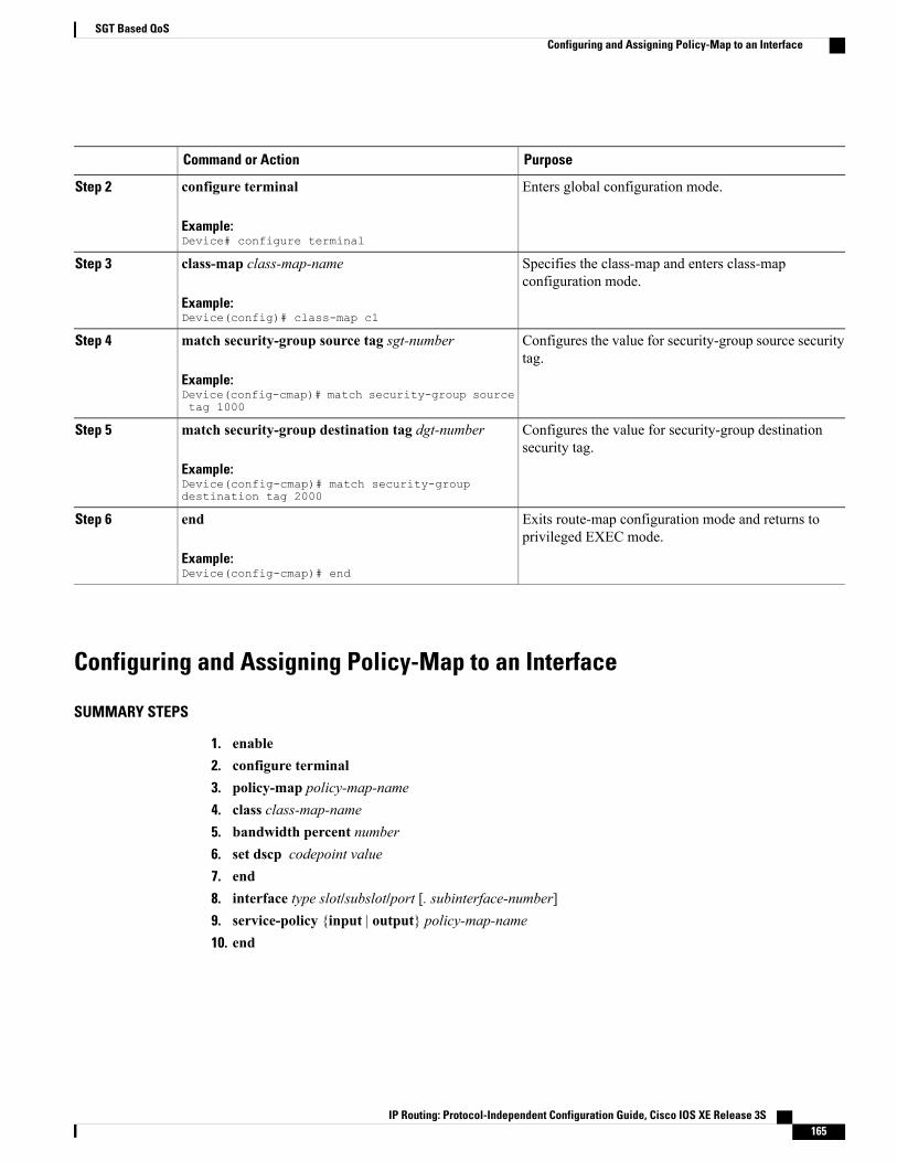
PurposeCommand or Action
Enters global configuration mode.configure terminal
Example:Device# configure terminal
Step 2
Specifies the class-map and enters class-mapconfiguration mode.
class-map class-map-name
Example:Device(config)# class-map c1
Step 3
Configures the value for security-group source securitytag.
match security-group source tag sgt-number
Example:Device(config-cmap)# match security-group sourcetag 1000
Step 4
Configures the value for security-group destinationsecurity tag.
match security-group destination tag dgt-number
Example:Device(config-cmap)# match security-groupdestination tag 2000
Step 5
Exits route-map configuration mode and returns toprivileged EXEC mode.
end
Example:Device(config-cmap)# end
Step 6
Configuring and Assigning Policy-Map to an Interface
SUMMARY STEPS
1. enable2. configure terminal3. policy-map policy-map-name4. class class-map-name5. bandwidth percent number6. set dscp codepoint value7. end8. interface type slot/subslot/port [. subinterface-number]9. service-policy {input | output} policy-map-name10. end
IP Routing: Protocol-Independent Configuration Guide, Cisco IOS XE Release 3S 165
SGT Based QoSConfiguring and Assigning Policy-Map to an Interface

DETAILED STEPS
PurposeCommand or Action
Enables privileged EXEC mode.enableStep 1
Example:Device> enable
• Enter your password if prompted.
Enters global configuration mode.configure terminal
Example:Device# configure terminal
Step 2
Specifies the policy-map and enters policy-mapconfiguration mode.
policy-map policy-map-name
Example:Device(config)# policy-map p1
Step 3
Specifies the class and enters class configuration mode.class class-map-name
Example:Device(config-pmap)# class c1
Step 4
Configures the value for bandwidth percent.bandwidth percent number
Example:Device(config-pmap-c)# bandwidth percent 20
Step 5
Configures the Differentiated Services Code Point(DSCP) value.
set dscp codepoint value
Example:Device(config-pmap-c)# set dscp ef
Step 6
Exits policy-map class action configuration mode andreturns to privileged EXEC mode.
end
Example:Device(config-pmap-c)# end
Step 7
Specifies the interface information and enters interfaceconfiguration mode.
interface type slot/subslot/port [. subinterface-number]
Example:Device(config)#interface gigabitEthernet0/0/0.1
Step 8
Assigns policy-map to the input of an interface.service-policy {input | output} policy-map-name
Example:Device(config-if)# service-policy input p1
Step 9
Exits interface configuration mode and returns toprivileged EXEC mode.
end
Example:Device(config-if)# end
Step 10
IP Routing: Protocol-Independent Configuration Guide, Cisco IOS XE Release 3S166
SGT Based QoSConfiguring and Assigning Policy-Map to an Interface

Displaying and Verifying SGT Based QoS Configuration
SUMMARY STEPS
1. enable2. show class-map3. debug cpl provisioning{api | db | errors | ttc}
DETAILED STEPS
Step 1 enable
Example:Device> enableEnables privileged EXEC mode.
• Enter your password if prompted.
Step 2 show class-map
Example:Device# show class-map
Class Map match-any class-default (id 0)Match any
Class Map match-all c1 (id 1)Match security-group source tag 1000Match security-group destination tag 2000
Displays class-map information.
Step 3 debug cpl provisioning{api | db | errors | ttc}
Example:Device# debug cpl provisioning api
CPL Policy Provisioning Manager API calls debugging is onEnables debugging for Call Processing Language (CPL) provisioning.
Configuration Examples for SGT Based QoS
Example: Configuring User Group, Device, or Role Based QoS PoliciesThe following example shows how to configure User Group, Device, or Role Based QoS Policies:enableconfigure terminal
IP Routing: Protocol-Independent Configuration Guide, Cisco IOS XE Release 3S 167
SGT Based QoSDisplaying and Verifying SGT Based QoS Configuration

class-map c4match security-group source tag 7000match security-group destination tag 8000endpolicy-map p5class c4bandwidth percent 50set dscp efend
interface gigabitEthernet0/0/0.1service-policy input p5
Additional References for SGT Based QoSRelated Documents
Document TitleRelated Topic
Cisco IOS Master Command List, All ReleasesCisco IOS commands
Cisco IOS IP Routing Protocol IndependentCommand Reference
Cisco IOS IP Routing Protocol Independentcommands
Understanding Cisco TrustSecCisco TrustSec Overview
Technical Assistance
LinkDescription
http://www.cisco.com/cisco/web/support/index.htmlThe Cisco Support website provides extensive onlineresources, including documentation and tools fortroubleshooting and resolving technical issues withCisco products and technologies.
To receive security and technical information aboutyour products, you can subscribe to various services,such as the Product Alert Tool (accessed from FieldNotices), the Cisco Technical Services Newsletter,and Really Simple Syndication (RSS) Feeds.
Access to most tools on the Cisco Support websiterequires a Cisco.com user ID and password.
Feature Information for SGT Based QoSThe following table provides release information about the feature or features described in this module. Thistable lists only the software release that introduced support for a given feature in a given software releasetrain. Unless noted otherwise, subsequent releases of that software release train also support that feature.
IP Routing: Protocol-Independent Configuration Guide, Cisco IOS XE Release 3S168
SGT Based QoSAdditional References for SGT Based QoS

Use Cisco Feature Navigator to find information about platform support and Cisco software image support.To access Cisco Feature Navigator, go to www.cisco.com/go/cfn. An account on Cisco.com is not required.
Table 14: Feature Information for SGT Based QoS
Feature InformationReleasesFeature Name
The SGT Based QoS featuresupports classification of packetsbased on Security Group Tag(SGT) for grouping the traffic intouser groups and devices to matchthe defined QoS policies.
The following commands wereintroduced or modified: debug cplprovisioning, class-map matchsecurity-group destination tag,match security-group source tag,show class-map.
Cisco IOS XE Release 3.17SSGT Based QoS
IP Routing: Protocol-Independent Configuration Guide, Cisco IOS XE Release 3S 169
SGT Based QoSFeature Information for SGT Based QoS

IP Routing: Protocol-Independent Configuration Guide, Cisco IOS XE Release 3S170
SGT Based QoSFeature Information for SGT Based QoS
C H A P T E R 15Policy-Based Routing Default Next-Hop Routes
The Policy-Based RoutingDefault Next-HopRoute feature introduces the ability for packets that are forwardedas a result of the set ip default next-hop command to be switched at the hardware level. In prior softwarereleases, the packets to be forwarded that are generated from the route map for policy-based routing areswitched at the software level.
• Finding Feature Information, page 171
• Information About Policy-Based Routing Default Next-Hop Routes, page 172
• How to Configure Policy-Based Routing Default Next-Hop Routes, page 173
• Configuration Examples for Policy-Based Routing Default Next-Hop Routes, page 175
• Additional References, page 176
• Feature Information for Policy-Based Routing Default Next-Hop Routes, page 176
Finding Feature InformationYour software release may not support all the features documented in this module. For the latest caveats andfeature information, see Bug Search Tool and the release notes for your platform and software release. Tofind information about the features documented in this module, and to see a list of the releases in which eachfeature is supported, see the feature information table.
Use Cisco Feature Navigator to find information about platform support and Cisco software image support.To access Cisco Feature Navigator, go to www.cisco.com/go/cfn. An account on Cisco.com is not required.
IP Routing: Protocol-Independent Configuration Guide, Cisco IOS XE Release 3S 171

Information About Policy-Based Routing Default Next-HopRoutes
Policy-Based RoutingPolicy-based routing is a process whereby the device puts packets through a route map before routing them.The route map determines which packets are routed to which device next. You might enable policy-basedrouting if you want certain packets to be routed some way other than the obvious shortest path. Possibleapplications for policy-based routing are to provide equal access, protocol-sensitive routing, source-sensitiverouting, routing based on interactive versus batch traffic, and routing based on dedicated links. Policy-basedrouting is a more flexible mechanism for routing packets than destination routing.
To enable policy-based routing, you must identify which route map to use for policy-based routing and createthe route map. The route map itself specifies the match criteria and the resulting action if all of the matchclauses are met.
To enable policy-based routing on an interface, indicate which route map the device should use by using theip policy route-map map-tag command in interface configuration mode. A packet arriving on the specifiedinterface is subject to policy-based routing except when its destination IP address is the same as the IP addressof the device’s interface. This ip policy route-map command disables fast switching of all packets arrivingon this interface.
To define the route map to be used for policy-based routing, use the route-map map-tag [permit | deny][sequence-number] global configuration command.
To define the criteria by which packets are examined to learn if they will be policy-based routed, use eitherthematch length minimum-length maximum-length command or thematch ip address {access-list-number| access-list-name} [access-list-number | access-list-name] command or both in route map configuration mode.No match clause in the route map indicates all packets.
To display the cache entries in the policy route cache, use the show ip cache policy command.
Mediatrace will show statistics of incorrect interfaces with policy-based routing (PBR) if the PBR doesnot interact with CEF or Resource Reservation Protocol (RSVP). Hence configure PBR to interact withCEF or RSVP directly so that mediatrace collects statistics only on tunnel interfaces and not physicalinterfaces.
Note
Precedence Setting in the IP HeaderThe precedence setting in the IP header determines whether, during times of high traffic, the packets aretreated with more or less precedence than other packets. By default, the Cisco software leaves this valueuntouched; the header remains with the precedence value that it had.
The precedence bits in the IP header can be set in the device when policy-based routing is enabled. When thepackets containing those headers arrive at another device, the packets are ordered for transmission accordingto the precedence set, if the queueing feature is enabled. The device does not honor the precedence bits ifqueueing is not enabled; the packets are sent in FIFO order.
IP Routing: Protocol-Independent Configuration Guide, Cisco IOS XE Release 3S172
Policy-Based Routing Default Next-Hop RoutesInformation About Policy-Based Routing Default Next-Hop Routes

You can change the precedence setting, using either a number or name (the names came from RFC 791). Youcan enable other features that use the values in the set ip precedence route map configuration command todetermine precedence. The table below lists the possible numbers and their corresponding name, from lowestto highest precedence.
Table 15: IP Precedence Values
NameNumber
routine0
priority1
immediate2
flash3
flash-override4
critical5
internet6
network7
The set commands can be used with each other. They are evaluated in the order shown in the previous table.A usable next hop implies an interface. Once the local device finds a next hop and a usable interface, it routesthe packet.
How to Configure Policy-Based Routing Default Next-HopRoutes
Configuring Precedence for Policy-Based Routing Default Next-Hop RoutesPerform this task to configure the precedence of packets and specify where packets that pass the match criteriaare output.
The set ip next-hop and set ip default next-hop commands are similar but have a different order ofoperation. Configuring the set ip next-hop command causes the system to first use policy routing andthen use the routing table. Configuring the set ip default next-hop command causes the system to firstuse the routing table and then the policy-route-specified next hop.
Note
IP Routing: Protocol-Independent Configuration Guide, Cisco IOS XE Release 3S 173
Policy-Based Routing Default Next-Hop RoutesHow to Configure Policy-Based Routing Default Next-Hop Routes
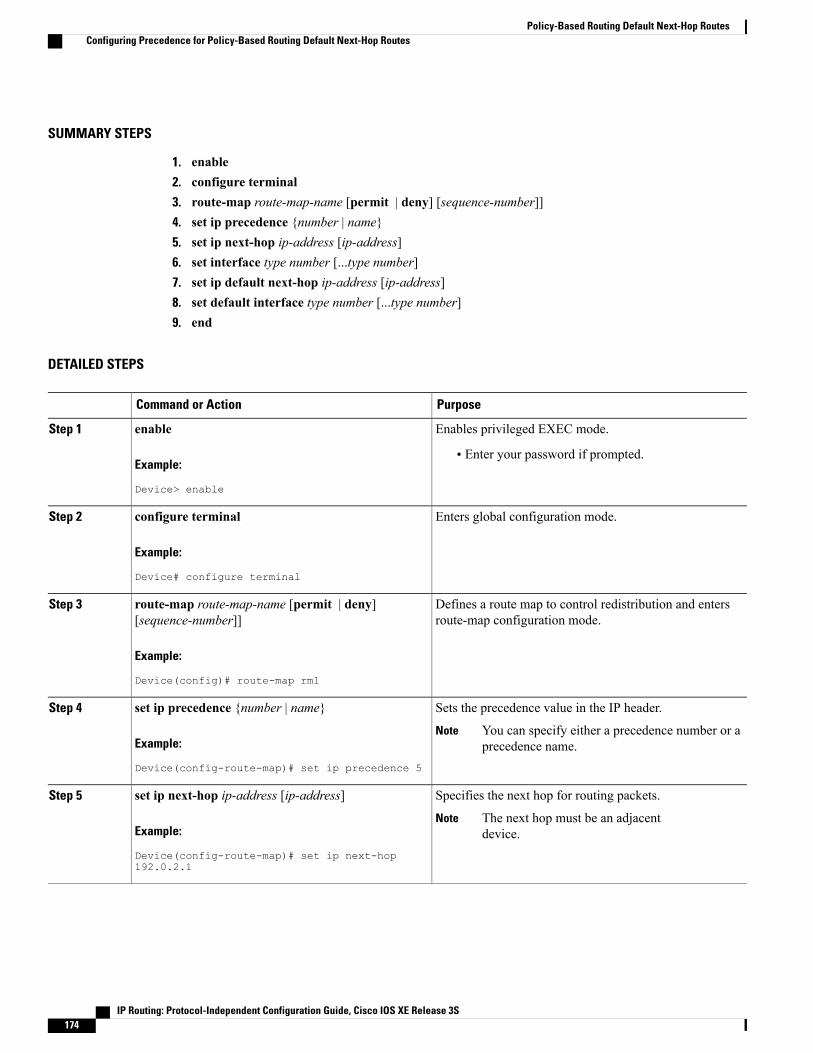
SUMMARY STEPS
1. enable2. configure terminal3. route-map route-map-name [permit | deny] [sequence-number]]4. set ip precedence {number | name}5. set ip next-hop ip-address [ip-address]6. set interface type number [...type number]7. set ip default next-hop ip-address [ip-address]8. set default interface type number [...type number]9. end
DETAILED STEPS
PurposeCommand or Action
Enables privileged EXEC mode.enableStep 1
Example:
Device> enable
• Enter your password if prompted.
Enters global configuration mode.configure terminal
Example:
Device# configure terminal
Step 2
Defines a route map to control redistribution and entersroute-map configuration mode.
route-map route-map-name [permit | deny][sequence-number]]
Example:
Device(config)# route-map rm1
Step 3
Sets the precedence value in the IP header.set ip precedence {number | name}Step 4
Example:
Device(config-route-map)# set ip precedence 5
You can specify either a precedence number or aprecedence name.
Note
Specifies the next hop for routing packets.set ip next-hop ip-address [ip-address]Step 5
Example:
Device(config-route-map)# set ip next-hop192.0.2.1
The next hop must be an adjacentdevice.
Note
IP Routing: Protocol-Independent Configuration Guide, Cisco IOS XE Release 3S174
Policy-Based Routing Default Next-Hop RoutesConfiguring Precedence for Policy-Based Routing Default Next-Hop Routes

PurposeCommand or Action
Specifies the output interface for the packet.set interface type number [...type number]
Example:
Device(config-route-map)# set interfacegigabitethernet 0/0/0
Step 6
Specifies the next hop for routing packets if there is noexplicit route for this destination.
set ip default next-hop ip-address [ip-address]
Example:
Device(config-route-map)# set ip defaultnext-hop 172.16.6.6
Step 7
Like the set ip next-hop command, the set ipdefault next-hop command must specify anadjacent device.
Note
Specifies the output interface for the packet if there is noexplicit route for the destination.
set default interface type number [...type number]
Example:
Device(config-route-map)# set default interfaceserial 0/0/0
Step 8
Exits route-map configuration mode and returns toprivileged EXEC mode.
end
Example:
Device(config-route-map)# end
Step 9
Configuration Examples for Policy-Based Routing DefaultNext-Hop Routes
Example: Policy-Based RoutingThe following example provides two sources with equal access to two different service providers. Packetsthat arrive on asynchronous interface 1/0/0 from the source 10.1.1.1 are sent to the device at 172.16.6.6 if thedevice has no explicit route for the destination of the packet. Packets that arrive from the source 172.17.2.2are sent to the device at 192.168.7.7 if the device has no explicit route for the destination of the packet. Allother packets for which the device has no explicit route to the destination are discarded.
Device(config)# access-list 1 permit ip 10.1.1.1Device(config)# access-list 2 permit ip 172.17.2.2Device(config)# interface async 1/0/0Device(config-if)# ip policy route-map equal-accessDevice(config-if)# exitDevice(config)# route-map equal-access permit 10Device(config-route-map)# match ip address 1Device(config-route-map)# set ip default next-hop 172.16.6.6Device(config-route-map)# exit
IP Routing: Protocol-Independent Configuration Guide, Cisco IOS XE Release 3S 175
Policy-Based Routing Default Next-Hop RoutesConfiguration Examples for Policy-Based Routing Default Next-Hop Routes

Device(config)# route-map equal-access permit 20Device(config-route-map)# match ip address 2Device(config-route-map)# set ip default next-hop 192.168.7.7Device(config-route-map)# exitDevice(config)# route-map equal-access permit 30Device(config-route-map)# set default interface null 0Device(config-route-map)# exit
Additional ReferencesRelated Documents
Document TitleRelated Topic
Cisco IOS Master Command List, All ReleasesCisco IOS commands
Cisco IOS IP Routing: Protocol-IndependentCommand Reference
IP routing protocol-independent commands
Technical Assistance
LinkDescription
http://www.cisco.com/cisco/web/support/index.htmlThe Cisco Support and Documentation websiteprovides online resources to download documentation,software, and tools. Use these resources to install andconfigure the software and to troubleshoot and resolvetechnical issues with Cisco products and technologies.Access to most tools on the Cisco Support andDocumentation website requires a Cisco.com user IDand password.
Feature Information for Policy-Based Routing Default Next-HopRoutes
The following table provides release information about the feature or features described in this module. Thistable lists only the software release that introduced support for a given feature in a given software releasetrain. Unless noted otherwise, subsequent releases of that software release train also support that feature.
Use Cisco Feature Navigator to find information about platform support and Cisco software image support.To access Cisco Feature Navigator, go to . An account on Cisco.com is not required.
IP Routing: Protocol-Independent Configuration Guide, Cisco IOS XE Release 3S176
Policy-Based Routing Default Next-Hop RoutesAdditional References

Table 16: Feature Information for Policy-Based Routing Default Next-Hop Routes
Feature InformationReleasesFeature Name
The Policy-Based Routing DefaultNext-Hop Route feature introducesthe ability for packets that areforwarded as a result of the set ipdefault next-hop command to beswitched at the hardware level. Inprior releases, the packets to beforwarded that were generatedfrom the route map forpolicy-based routingwere switchedat the software level.
The following command wasintroduced or modified: set ipdefault next-hop.
12.1(11)E
Cisco IOS XE Release 2.2
Policy-Based Routing DefaultNext-Hop Routes
IP Routing: Protocol-Independent Configuration Guide, Cisco IOS XE Release 3S 177
Policy-Based Routing Default Next-Hop RoutesFeature Information for Policy-Based Routing Default Next-Hop Routes

IP Routing: Protocol-Independent Configuration Guide, Cisco IOS XE Release 3S178
Policy-Based Routing Default Next-Hop RoutesFeature Information for Policy-Based Routing Default Next-Hop Routes

C H A P T E R 16PBR Next-Hop Verify Availability for VRF
The PBR Next-Hop Verify Availability for VRF feature enables verification of next-hop availability forIPv4/IPv6 packets in virtual routing and forwarding (VRF) instances.
• Finding Feature Information, page 179
• Information About PBR Next-Hop Verify Availability for VRF, page 179
• How to Configure PBR Next-Hop Verify Availability for VRF, page 180
• Configuration Examples for PBR Next-Hop Verify Availability for VRF, page 191
• Additional References for PBR Next-Hop Verify Availability for VRF, page 193
• Feature Information for PBR Next-Hop Verify Availability for VRF, page 193
Finding Feature InformationYour software release may not support all the features documented in this module. For the latest caveats andfeature information, see Bug Search Tool and the release notes for your platform and software release. Tofind information about the features documented in this module, and to see a list of the releases in which eachfeature is supported, see the feature information table.
Use Cisco Feature Navigator to find information about platform support and Cisco software image support.To access Cisco Feature Navigator, go to www.cisco.com/go/cfn. An account on Cisco.com is not required.
Information About PBR Next-Hop Verify Availability for VRF
PBR Next-Hop Verify Availability for VRF OverviewCisco IOS policy-based routing (PBR) defines packet matching and classification specifications, sets actionpolicies, which can modify the attributes of IP packets, and overrides normal destination IP address-basedrouting and forwarding. PBR can be applied on global interfaces and under multiple routing instances. ThePBRNext-Hop Verify Availability for VRF feature enables verification of next-hop availability for IPv4/IPv6packets under virtual routing and forwarding (VRF) instances.
IP Routing: Protocol-Independent Configuration Guide, Cisco IOS XE Release 3S 179
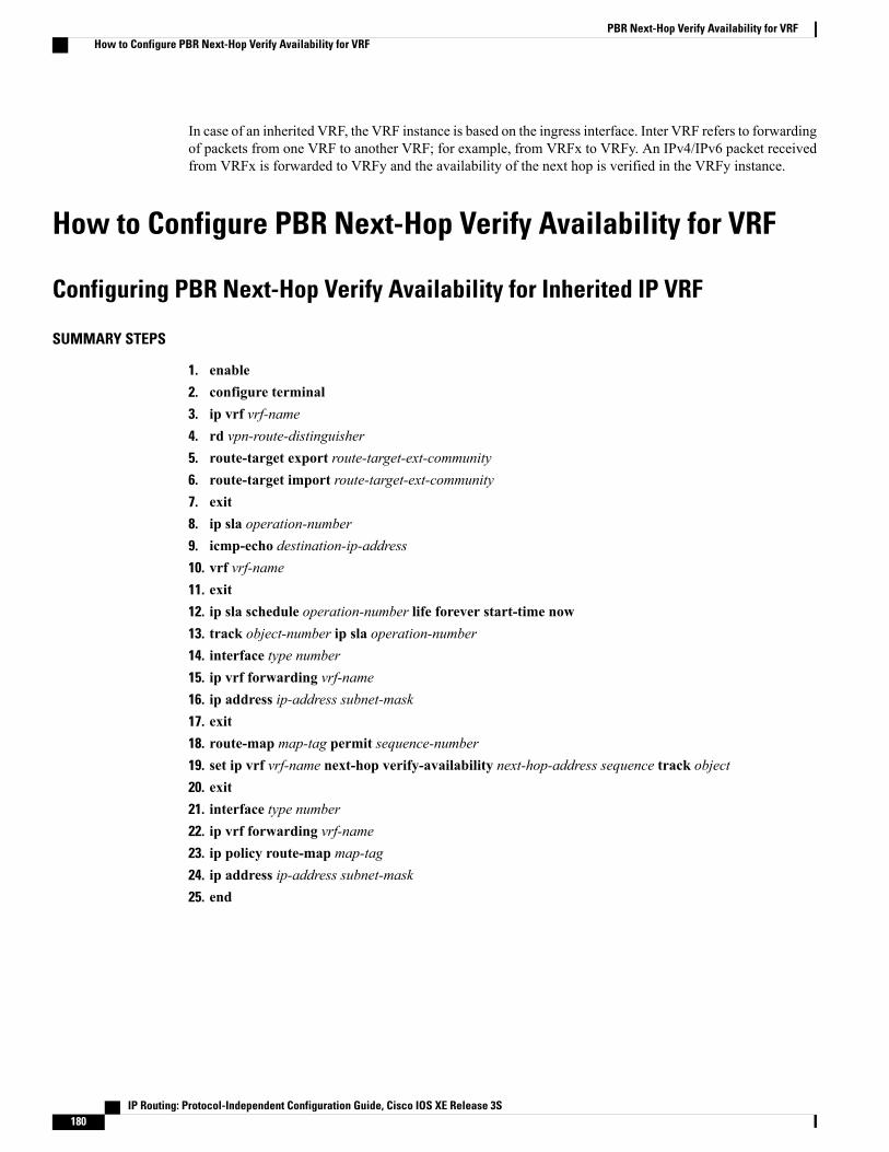
In case of an inherited VRF, the VRF instance is based on the ingress interface. Inter VRF refers to forwardingof packets from one VRF to another VRF; for example, from VRFx to VRFy. An IPv4/IPv6 packet receivedfrom VRFx is forwarded to VRFy and the availability of the next hop is verified in the VRFy instance.
How to Configure PBR Next-Hop Verify Availability for VRF
Configuring PBR Next-Hop Verify Availability for Inherited IP VRF
SUMMARY STEPS
1. enable2. configure terminal3. ip vrf vrf-name4. rd vpn-route-distinguisher5. route-target export route-target-ext-community6. route-target import route-target-ext-community7. exit8. ip sla operation-number9. icmp-echo destination-ip-address10. vrf vrf-name11. exit12. ip sla schedule operation-number life forever start-time now13. track object-number ip sla operation-number14. interface type number15. ip vrf forwarding vrf-name16. ip address ip-address subnet-mask17. exit18. route-map map-tag permit sequence-number19. set ip vrf vrf-name next-hop verify-availability next-hop-address sequence track object20. exit21. interface type number22. ip vrf forwarding vrf-name23. ip policy route-map map-tag24. ip address ip-address subnet-mask25. end
IP Routing: Protocol-Independent Configuration Guide, Cisco IOS XE Release 3S180
PBR Next-Hop Verify Availability for VRFHow to Configure PBR Next-Hop Verify Availability for VRF
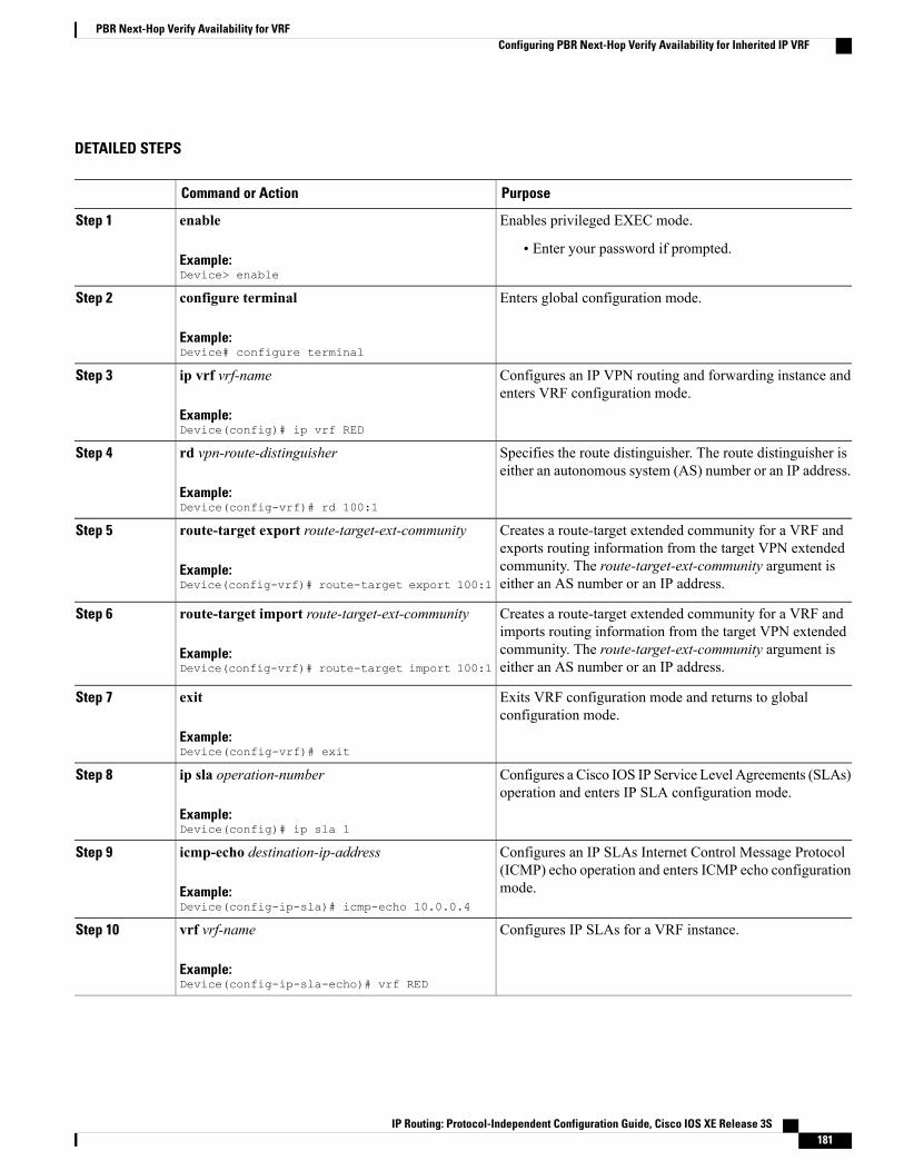
DETAILED STEPS
PurposeCommand or Action
Enables privileged EXEC mode.enable
Example:Device> enable
Step 1
• Enter your password if prompted.
Enters global configuration mode.configure terminal
Example:Device# configure terminal
Step 2
Configures an IP VPN routing and forwarding instance andenters VRF configuration mode.
ip vrf vrf-name
Example:Device(config)# ip vrf RED
Step 3
Specifies the route distinguisher. The route distinguisher iseither an autonomous system (AS) number or an IP address.
rd vpn-route-distinguisher
Example:Device(config-vrf)# rd 100:1
Step 4
Creates a route-target extended community for a VRF andexports routing information from the target VPN extended
route-target export route-target-ext-community
Example:Device(config-vrf)# route-target export 100:1
Step 5
community. The route-target-ext-community argument iseither an AS number or an IP address.
Creates a route-target extended community for a VRF andimports routing information from the target VPN extended
route-target import route-target-ext-community
Example:Device(config-vrf)# route-target import 100:1
Step 6
community. The route-target-ext-community argument iseither an AS number or an IP address.
Exits VRF configuration mode and returns to globalconfiguration mode.
exit
Example:Device(config-vrf)# exit
Step 7
Configures a Cisco IOS IP Service Level Agreements (SLAs)operation and enters IP SLA configuration mode.
ip sla operation-number
Example:Device(config)# ip sla 1
Step 8
Configures an IP SLAs Internet Control Message Protocol(ICMP) echo operation and enters ICMP echo configurationmode.
icmp-echo destination-ip-address
Example:Device(config-ip-sla)# icmp-echo 10.0.0.4
Step 9
Configures IP SLAs for a VRF instance.vrf vrf-name
Example:Device(config-ip-sla-echo)# vrf RED
Step 10
IP Routing: Protocol-Independent Configuration Guide, Cisco IOS XE Release 3S 181
PBR Next-Hop Verify Availability for VRFConfiguring PBR Next-Hop Verify Availability for Inherited IP VRF

PurposeCommand or Action
Exits ICMP echo configuration mode and returns to globalconfiguration mode.
exit
Example:Device(config-ip-sla-echo)# exit
Step 11
Configures the scheduling parameters for a single Cisco IOSIP SLAs operation.
ip sla schedule operation-number life foreverstart-time now
Example:Device(config)# ip sla schedule 1 life foreverstart-time now
Step 12
Tracks the state of a Cisco IOS IP SLAs operation and enterstracking configuration mode.
track object-number ip sla operation-number
Example:Device(config)# track 1 ip sla 1
Step 13
Specifies the interface type and number and enters interfaceconfiguration mode.
interface type number
Example:Device(config-track)# interface Ethernet1/0
Step 14
Configures the forwarding table.ip vrf forwarding vrf-name
Example:Device(config-if)# ip vrf forwarding RED
Step 15
Specifies the IP address and subnet mask for the interface.ip address ip-address subnet-mask
Example:Device(config-if)# ip address 10.0.0.2255.0.0.0
Step 16
Exits interface configuration mode and returns to globalconfiguration mode.
exit
Example:Device(config-if)# exit
Step 17
Specifies the sequence to insert to or delete from an existingroute-map entry and enters route-map configuration mode.
route-map map-tag permit sequence-number
Example:Device(config)# route-map test02 permit 10
Step 18
Configures policy routing to verify the reachability of thenext hop of a route map before the router performs policyrouting to that next hop.
set ip vrf vrf-name next-hop verify-availabilitynext-hop-address sequence track object
Example:Device(config-route-map)# set ip vrf REDnext-hop verify-availability 192.168.23.2 1track 1
Step 19
Exits route-map configuration mode and returns to globalconfiguration mode.
exit
Example:Device(config-route-map)# exit
Step 20
IP Routing: Protocol-Independent Configuration Guide, Cisco IOS XE Release 3S182
PBR Next-Hop Verify Availability for VRFConfiguring PBR Next-Hop Verify Availability for Inherited IP VRF
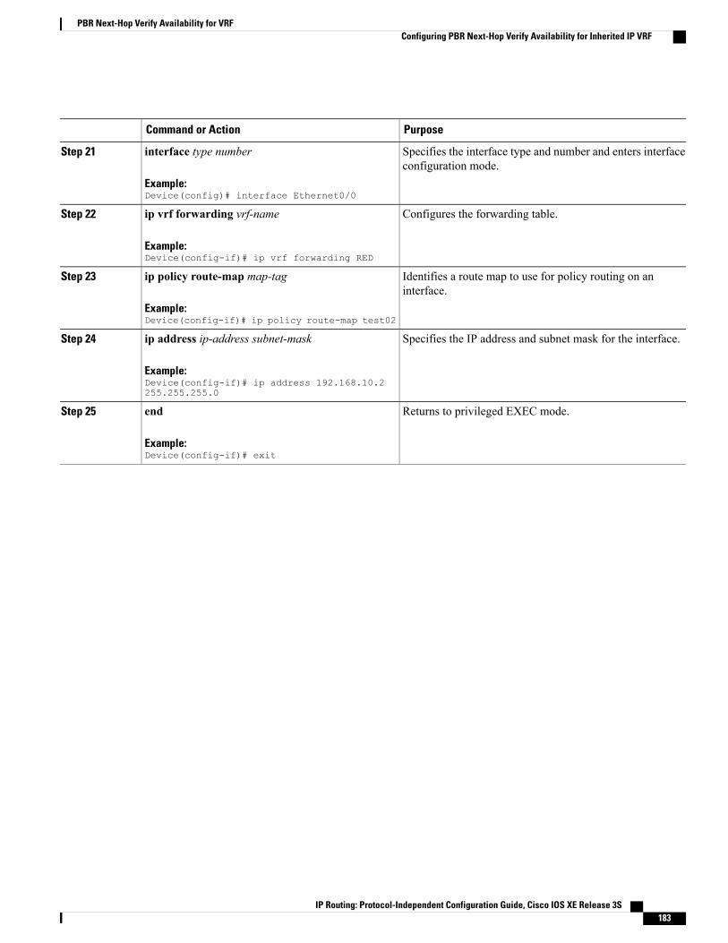
PurposeCommand or Action
Specifies the interface type and number and enters interfaceconfiguration mode.
interface type number
Example:Device(config)# interface Ethernet0/0
Step 21
Configures the forwarding table.ip vrf forwarding vrf-name
Example:Device(config-if)# ip vrf forwarding RED
Step 22
Identifies a route map to use for policy routing on aninterface.
ip policy route-map map-tag
Example:Device(config-if)# ip policy route-map test02
Step 23
Specifies the IP address and subnet mask for the interface.ip address ip-address subnet-mask
Example:Device(config-if)# ip address 192.168.10.2255.255.255.0
Step 24
Returns to privileged EXEC mode.end
Example:Device(config-if)# exit
Step 25
IP Routing: Protocol-Independent Configuration Guide, Cisco IOS XE Release 3S 183
PBR Next-Hop Verify Availability for VRFConfiguring PBR Next-Hop Verify Availability for Inherited IP VRF
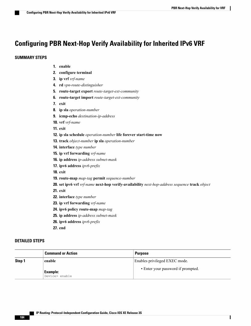
Configuring PBR Next-Hop Verify Availability for Inherited IPv6 VRF
SUMMARY STEPS
1. enable2. configure terminal3. ip vrf vrf-name4. rd vpn-route-distinguisher5. route-target export route-target-ext-community6. route-target import route-target-ext-community7. exit8. ip sla operation-number9. icmp-echo destination-ip-address10. vrf vrf-name11. exit12. ip sla schedule operation-number life forever start-time now13. track object-number ip sla operation-number14. interface type number15. ip vrf forwarding vrf-name16. ip address ip-address subnet-mask17. ipv6 address ipv6-prefix18. exit19. route-map map-tag permit sequence-number20. set ipv6 vrf vrf-name next-hop verify-availability next-hop-address sequence track object21. exit22. interface type number23. ip vrf forwarding vrf-name24. ipv6 policy route-map map-tag25. ip address ip-address subnet-mask26. ipv6 address ipv6-prefix27. end
DETAILED STEPS
PurposeCommand or Action
Enables privileged EXEC mode.enable
Example:Device> enable
Step 1
• Enter your password if prompted.
IP Routing: Protocol-Independent Configuration Guide, Cisco IOS XE Release 3S184
PBR Next-Hop Verify Availability for VRFConfiguring PBR Next-Hop Verify Availability for Inherited IPv6 VRF

PurposeCommand or Action
Enters global configuration mode.configure terminal
Example:Device# configure terminal
Step 2
Configures an IP VPN routing and forwarding instance andenters VRF configuration mode.
ip vrf vrf-name
Example:Device(config)# ip vrf RED
Step 3
Specifies the route distinguisher. The route distinguisher iseither an autonomous system (AS) number or an IP address.
rd vpn-route-distinguisher
Example:Device(config-vrf)# rd 100:1
Step 4
Creates a route-target extended community for a VRF andexports routing information from the target VPN extended
route-target export route-target-ext-community
Example:Device(config-vrf)# route-target export 100:1
Step 5
community. The route-target-ext-community argument iseither an AS number or an IP address.
Creates a route-target extended community for a VRF andimports routing information from the target VPN extended
route-target import route-target-ext-community
Example:Device(config-vrf)# route-target import 100:1
Step 6
community. The route-target-ext-community argument iseither an AS number or an IP address.
Exits VRF configuration mode and returns to globalconfiguration mode.
exit
Example:Device(config-vrf)# exit
Step 7
Configures a Cisco IOS IP Service Level Agreements(SLAs) operation and enters IP SLA configuration mode.
ip sla operation-number
Example:Device(config)# ip sla 1
Step 8
Configures an IP SLAs Internet Control Message Protocol(ICMP) echo operation and enters ICMP echo configurationmode.
icmp-echo destination-ip-address
Example:Device(config-ip-sla)# icmp-echo 10.0.0.4
Step 9
Configures IP SLAs for a VRF instance.vrf vrf-name
Example:Device(config-ip-sla-echo)# vrf RED
Step 10
Exits ICMP echo configuration mode and returns to globalconfiguration mode.
exit
Example:Device(config-ip-sla-echo)# exit
Step 11
IP Routing: Protocol-Independent Configuration Guide, Cisco IOS XE Release 3S 185
PBR Next-Hop Verify Availability for VRFConfiguring PBR Next-Hop Verify Availability for Inherited IPv6 VRF
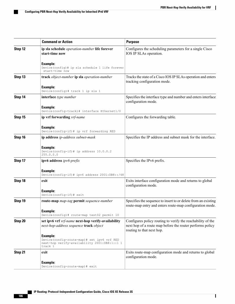
PurposeCommand or Action
Configures the scheduling parameters for a single CiscoIOS IP SLAs operation.
ip sla schedule operation-number life foreverstart-time now
Example:Device(config)# ip sla schedule 1 life foreverstart-time now
Step 12
Tracks the state of a Cisco IOS IP SLAs operation and enterstracking configuration mode.
track object-number ip sla operation-number
Example:Device(config)# track 1 ip sla 1
Step 13
Specifies the interface type and number and enters interfaceconfiguration mode.
interface type number
Example:Device(config-track)# interface Ethernet1/0
Step 14
Configures the forwarding table.ip vrf forwarding vrf-name
Example:Device(config-if)# ip vrf forwarding RED
Step 15
Specifies the IP address and subnet mask for the interface.ip address ip-address subnet-mask
Example:Device(config-if)# ip address 10.0.0.2255.0.0.0
Step 16
Specifies the IPv6 prefix.ipv6 address ipv6-prefix
Example:Device(config-if)# ipv6 address 2001:DB8::/48
Step 17
Exits interface configuration mode and returns to globalconfiguration mode.
exit
Example:Device(config-if)# exit
Step 18
Specifies the sequence to insert to or delete from an existingroute-map entry and enters route-map configuration mode.
route-map map-tag permit sequence-number
Example:Device(config)# route-map test02 permit 10
Step 19
Configures policy routing to verify the reachability of thenext hop of a route map before the router performs policyrouting to that next hop.
set ipv6 vrf vrf-name next-hop verify-availabilitynext-hop-address sequence track object
Example:Device(config-route-map)# set ipv6 vrf REDnext-hop verify-availability 2001:DB8:1::1 1track 1
Step 20
Exits route-map configuration mode and returns to globalconfiguration mode.
exit
Example:Device(config-route-map)# exit
Step 21
IP Routing: Protocol-Independent Configuration Guide, Cisco IOS XE Release 3S186
PBR Next-Hop Verify Availability for VRFConfiguring PBR Next-Hop Verify Availability for Inherited IPv6 VRF

PurposeCommand or Action
Specifies the interface type and number and enters interfaceconfiguration mode.
interface type number
Example:Device(config)# interface Ethernet0/0
Step 22
Configures the forwarding table.ip vrf forwarding vrf-name
Example:Device(config-if)# ip vrf forwarding RED
Step 23
Identifies a route map to use for policy routing on aninterface.
ipv6 policy route-map map-tag
Example:Device(config-if)# ipv6 policy route-maptest02
Step 24
Specifies the IP address and subnet mask for the interface.ip address ip-address subnet-mask
Example:Device(config-if)# ip address 192.168.10.2255.255.255.0
Step 25
Specifies the IPv6 prefix.ipv6 address ipv6-prefix
Example:Device(config-if)# ipv6 address 2001:DB8::/32
Step 26
Returns to privileged EXEC mode.end
Example:Device(config-if)# end
Step 27
IP Routing: Protocol-Independent Configuration Guide, Cisco IOS XE Release 3S 187
PBR Next-Hop Verify Availability for VRFConfiguring PBR Next-Hop Verify Availability for Inherited IPv6 VRF
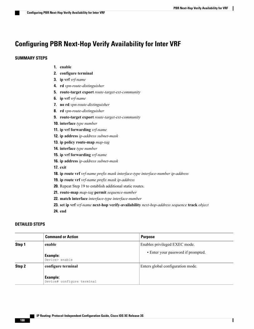
Configuring PBR Next-Hop Verify Availability for Inter VRF
SUMMARY STEPS
1. enable2. configure terminal3. ip vrf vrf-name4. rd vpn-route-distinguisher5. route-target export route-target-ext-community6. ip vrf vrf-name7. no rd vpn-route-distinguisher8. rd vpn-route-distinguisher9. route-target export route-target-ext-community10. interface type number11. ip vrf forwarding vrf-name12. ip address ip-address subnet-mask13. ip policy route-map map-tag14. interface type number15. ip vrf forwarding vrf-name16. ip address ip-address subnet-mask17. exit18. ip route vrf vrf-name prefix mask interface-type interface-number ip-address19. ip route vrf vrf-name prefix mask ip-address20. Repeat Step 19 to establish additional static routes.21. route-map map-tag permit sequence-number22. match interface interface-type interface-number23. set ip vrf vrf-name next-hop verify-availability next-hop-address sequence track object24. end
DETAILED STEPS
PurposeCommand or Action
Enables privileged EXEC mode.enable
Example:Device> enable
Step 1
• Enter your password if prompted.
Enters global configuration mode.configure terminal
Example:Device# configure terminal
Step 2
IP Routing: Protocol-Independent Configuration Guide, Cisco IOS XE Release 3S188
PBR Next-Hop Verify Availability for VRFConfiguring PBR Next-Hop Verify Availability for Inter VRF
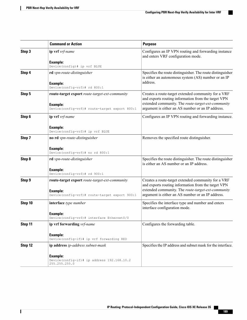
PurposeCommand or Action
Configures an IP VPN routing and forwarding instanceand enters VRF configuration mode.
ip vrf vrf-name
Example:Device(config)# ip vrf BLUE
Step 3
Specifies the route distinguisher. The route distinguisheris either an autonomous system (AS) number or an IPaddress.
rd vpn-route-distinguisher
Example:Device(config-vrf)# rd 800:1
Step 4
Creates a route-target extended community for a VRFand exports routing information from the target VPN
route-target export route-target-ext-community
Example:Device(config-vrf)# route-target export 800:1
Step 5
extended community. The route-target-ext-communityargument is either an AS number or an IP address.
Configures an IP VPN routing and forwarding instance.ip vrf vrf-name
Example:Device(config-vrf)# ip vrf BLUE
Step 6
Removes the specified route distinguisher.no rd vpn-route-distinguisher
Example:Device(config-vrf)# no rd 800:1
Step 7
Specifies the route distinguisher. The route distinguisheris either an AS number or an IP address.
rd vpn-route-distinguisher
Example:Device(config-vrf)# rd 900:1
Step 8
Creates a route-target extended community for a VRFand exports routing information from the target VPN
route-target export route-target-ext-community
Example:Device(config-vrf)# route-target export 900:1
Step 9
extended community. The route-target-ext-communityargument is either an AS number or an IP address.
Specifies the interface type and number and entersinterface configuration mode.
interface type number
Example:Device(config-vrf)# interface Ethernet0/0
Step 10
Configures the forwarding table.ip vrf forwarding vrf-name
Example:Device(config-if)# ip vrf forwarding RED
Step 11
Specifies the IP address and subnet mask for the interface.ip address ip-address subnet-mask
Example:Device(config-if)# ip address 192.168.10.2255.255.255.0
Step 12
IP Routing: Protocol-Independent Configuration Guide, Cisco IOS XE Release 3S 189
PBR Next-Hop Verify Availability for VRFConfiguring PBR Next-Hop Verify Availability for Inter VRF
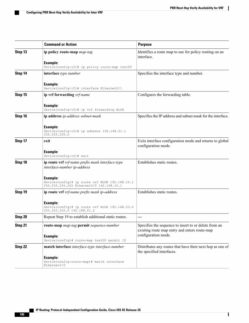
PurposeCommand or Action
Identifies a route map to use for policy routing on aninterface.
ip policy route-map map-tag
Example:Device(config-if)# ip policy route-map test00
Step 13
Specifies the interface type and number.interface type number
Example:Device(config-if)# interface Ethernet0/1
Step 14
Configures the forwarding table.ip vrf forwarding vrf-name
Example:Device(config-if)# ip vrf forwarding BLUE
Step 15
Specifies the IP address and subnet mask for the interface.ip address ip-address subnet-mask
Example:Device(config-if)# ip address 192.168.21.1255.255.255.0
Step 16
Exits interface configuration mode and returns to globalconfiguration mode.
exit
Example:Device(config-if)# exit
Step 17
Establishes static routes.ip route vrf vrf-name prefix mask interface-typeinterface-number ip-address
Step 18
Example:Device(config)# ip route vrf BLUE 192.168.10.1255.255.255.255 Ethernet0/0 192.168.10.1
Establishes static routes.ip route vrf vrf-name prefix mask ip-address
Example:Device(config)# ip route vrf BLUE 192.168.23.0255.255.255.0 192.168.21.2
Step 19
—Repeat Step 19 to establish additional static routes.Step 20
Specifies the sequence to insert to or delete from anexisting route map entry and enters route-mapconfiguration mode.
route-map map-tag permit sequence-number
Example:Device(config)# route-map test00 permit 10
Step 21
Distributes any routes that have their next hop as one ofthe specified interfaces.
match interface interface-type interface-number
Example:Device(config-route-map)# match interfaceEthernet0/0
Step 22
IP Routing: Protocol-Independent Configuration Guide, Cisco IOS XE Release 3S190
PBR Next-Hop Verify Availability for VRFConfiguring PBR Next-Hop Verify Availability for Inter VRF

PurposeCommand or Action
Configures policy routing to verify the reachability ofthe next hop of a route map of a VRF instance before therouter performs policy routing to that next hop.
set ip vrf vrf-name next-hop verify-availabilitynext-hop-address sequence track object
Example:Device(config-route-map)# set ip vrf BLUEnext-hop verify-availability 192.168.23.2 1 track1
Step 23
Returns to privileged EXEC mode.end
Example:Device(config-route-map)# end
Step 24
Configuration Examples for PBR Next-Hop Verify Availabilityfor VRF
Example: Configuring PBR Next-Hop Verify Availability for Inherited IP VRF
Device> enableDevice# configure terminalDevice(config)# ip vrf REDDevice(config-vrf)# rd 100:1Device(config-vrf)# route-target export 100:1Device(config-vrf)# route-target import 100:1Device(config-vrf)# exitDevice(config)# ip sla 1Device(config-ip-sla)# icmp-echo 10.0.0.4Device(config-ip-sla-echo)# vrf REDDevice(config-ip-sla-echo)# exitDevice(config)# ip sla schedule 1 life forever start-time nowDevice(config)# track 1 ip sla 1Device(config-track)# interface Ethernet0/0Device(config-if)# ip vrf forwarding REDDevice(config-if)# ip address 10.0.0.2 255.0.0.0Device(config-if)# exitDevice(config)# route-map test02 permit 10Device(config-route-map)# set ip vrf RED next-hop verify-availability 192.168.23.2 1 track1Device(config-route-map)# interface Ethernet0/0Device(config-if)# ip vrf forwarding REDDevice(config-if)# ip policy route-map test02Device(config-if)# ip address 192.168.10.2 255.255.255.0Device(config-if)# end
Example: Configuring PBR Next-Hop Verify Availability for Inherited IPv6 VRF
Device> enableDevice# configure terminal
IP Routing: Protocol-Independent Configuration Guide, Cisco IOS XE Release 3S 191
PBR Next-Hop Verify Availability for VRFConfiguration Examples for PBR Next-Hop Verify Availability for VRF

Device(config)# ip vrf REDDevice(config-vrf)# rd 100:1Device(config-vrf)# route-target export 100:1Device(config-vrf)# route-target import 100:1Device(config-vrf)# exitDevice(config)# ip sla 1Device(config-ip-sla)# icmp-echo 10.0.0.4Device(config-ip-sla-echo)# vrf REDDevice(config-ip-sla-echo)# exitDevice(config)# ip sla schedule 1 life forever start-time nowDevice(config)# track 1 ip sla 1Device(config-track)# interface Ethernet0/0Device(config-if)# ip vrf forwarding REDDevice(config-if)# ip policy route-map test02Device(config-if)# ip address 192.168.10.2 255.255.255.0Device(config-if)# ipv6 address 2001:DB8::/32Device(config-if)# interface Ethernet1/0Device(config-if)# ip vrf forwarding REDDevice(config-if)# ip address 10.0.0.2 255.0.0.0Device(config-if)# ipv6 address 2001:DB8::/48Device(config-if)# exitDevice(config)# route-map test02 permit 10Device(config-route-map)# set ipv6 vrf RED next-hop verify-availability 2001:DB8:1::1 1track 1Device(config-route-map)# end
Example: Configuring PBR Next-Hop Verify Availability for Inter VRF
Device> enableDevice# configure terminalDevice(config)# ip vrf BLUEDevice(config-vrf)# rd 800:1Device(config-vrf)# route-target export 800:1Device(config-vrf)# ip vrf BLUEDevice(config-vrf)# no rd 800:1Device(config-vrf)# rd 900:1Device(config-vrf)# route-target export 900:1Device(config-vrf)# interface Ethernet0/0Device(config-if)# ip vrf forwarding REDDevice(config-if)# ip address 192.168.10.2 255.255.255.0Device(config-if)# ip policy route-map test00Device(config-if)# interface Ethernet0/1Device(config-if)# ip vrf forwarding BLUEDevice(config-if)# ip address 192.168.21.1 255.255.255.0Device(config-if)# exitDevice(config)# ip route vrf blue 192.168.10.1 255.255.255.255 Ethernet0/0 192.168.10.1Device(config)# ip route vrf blue 192.168.23.0 255.255.255.0 192.168.21.2Device(config)# route-map test00 permit 10Device(config-route-map)# match interface Ethernet0/0Device(config-route-map)# set ip vrf blue next-hop verify-availability 192.168.23.2 1 track1Device(config-route-map)# end
IP Routing: Protocol-Independent Configuration Guide, Cisco IOS XE Release 3S192
PBR Next-Hop Verify Availability for VRFExample: Configuring PBR Next-Hop Verify Availability for Inter VRF

Additional References for PBR Next-Hop Verify Availability forVRF
Related Documents
Document TitleRelated Topic
Cisco IOS Master Command List, All ReleasesCisco IOS commands
Technical Assistance
LinkDescription
http://www.cisco.com/supportThe Cisco Support website provides extensive onlineresources, including documentation and tools fortroubleshooting and resolving technical issues withCisco products and technologies.
To receive security and technical information aboutyour products, you can subscribe to various services,such as the Product Alert Tool (accessed from FieldNotices), the Cisco Technical Services Newsletter,and Really Simple Syndication (RSS) Feeds.
Access to most tools on the Cisco Support websiterequires a Cisco.com user ID and password.
Feature Information for PBR Next-Hop Verify Availability forVRF
The following table provides release information about the feature or features described in this module. Thistable lists only the software release that introduced support for a given feature in a given software releasetrain. Unless noted otherwise, subsequent releases of that software release train also support that feature.
Use Cisco Feature Navigator to find information about platform support and Cisco software image support.To access Cisco Feature Navigator, go to . An account on Cisco.com is not required.
Feature InformationReleasesFeature Name
The PBR Next-Hop VerifyAvailability for VRF featureenables verification of next-hopavailability for IPv4/IPv6 packetsin virtual routing and forwarding(VRF) instances.
Cisco IOS XE Release 3.11SPBRNext-Hop Verify Availabilityfor VRF
IP Routing: Protocol-Independent Configuration Guide, Cisco IOS XE Release 3S 193
PBR Next-Hop Verify Availability for VRFAdditional References for PBR Next-Hop Verify Availability for VRF

IP Routing: Protocol-Independent Configuration Guide, Cisco IOS XE Release 3S194
PBR Next-Hop Verify Availability for VRFFeature Information for PBR Next-Hop Verify Availability for VRF
C H A P T E R 17QoS Policy Propagation via BGP
The QoS Policy Propagation via BGP feature allows you to classify packets by IP precedence based on theBorder Gateway Protocol (BGP) community lists, BGP autonomous system paths, and access lists. Afterpackets have been classified, you can use other quality of service (QoS) features such as committed accessrate (CAR) and Weighted Random Early Detection (WRED) to specify and enforce policies to fit yourbusiness model.
• Finding Feature Information, page 195
• Prerequisites for QoS Policy Propagation via BGP, page 195
• Information About QoS Policy Propagation via BGP, page 196
• How to Configure QoS Policy Propagation via BGP, page 196
• Configuration Examples for QoS Policy Propagation via BGP, page 203
• Additional References, page 206
• Feature Information for QoS Policy Propagation via BGP, page 207
Finding Feature InformationYour software release may not support all the features documented in this module. For the latest caveats andfeature information, see Bug Search Tool and the release notes for your platform and software release. Tofind information about the features documented in this module, and to see a list of the releases in which eachfeature is supported, see the feature information table.
Use Cisco Feature Navigator to find information about platform support and Cisco software image support.To access Cisco Feature Navigator, go to www.cisco.com/go/cfn. An account on Cisco.com is not required.
Prerequisites for QoS Policy Propagation via BGP• Enable the Border Gateway Protocol (BGP) and Cisco Express Forwarding (CEF) or distributed CEF(dCEF) on the device. Subinterfaces on an ATM interface that have the bgp-policy command enabledmust use CEF mode because dCEF is not supported. dCEF uses the Versatile Interface Processor (VIP)rather than the Route Switch Processor (RSP) to perform forwarding functions.
IP Routing: Protocol-Independent Configuration Guide, Cisco IOS XE Release 3S 195
• Define the policy.
• Apply the policy through BGP.
• Configure the BGP community list, BGP autonomous system path, or access list and enable the policyon an interface.
• Enable committed access rate (CAR) or Weighted Random Early Detection (WRED) to use the policy.
Information About QoS Policy Propagation via BGP
Benefits of QoS Policy Propagation via BGPThe QoS Policy Propagation via BGP feature allows you to classify packets by IP precedence based on BorderGateway Protocol (BGP) community lists, BGP autonomous system paths, and access lists. After a packethas been classified, you can use other quality of service (QoS) features such as committed access rate (CAR)and Weighted Random Early Detection (WRED) to specify and enforce policies to fit your business model.
How to Configure QoS Policy Propagation via BGP
Configuring QoS Policy Propagation via BGP Based on Community Lists
SUMMARY STEPS
1. enable2. configure terminal3. route-map route-map-name [permit | deny [sequence-number]]4. match community {standard-list-number | expanded-list-number | community-list-name [exact]}5. set ip precedence [number | name]6. exit7. router bgp autonomous-system8. table-map route-map-name9. exit10. ip community-list standard-list-number {permit | deny} [community-number]11. interface type number12. bgp-policy {source | destination} ip-prec-map13. exit14. ip bgp-community new-format15. end
IP Routing: Protocol-Independent Configuration Guide, Cisco IOS XE Release 3S196
QoS Policy Propagation via BGPInformation About QoS Policy Propagation via BGP
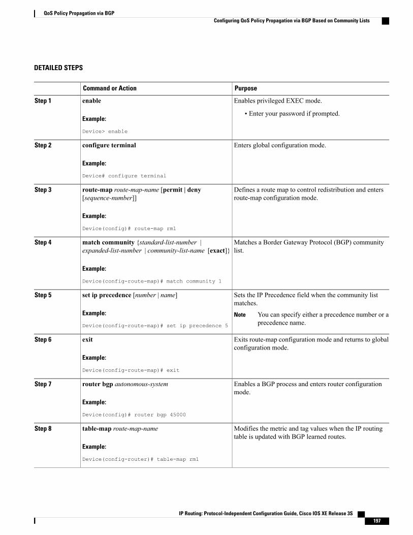
DETAILED STEPS
PurposeCommand or Action
Enables privileged EXEC mode.enableStep 1
Example:
Device> enable
• Enter your password if prompted.
Enters global configuration mode.configure terminal
Example:
Device# configure terminal
Step 2
Defines a route map to control redistribution and entersroute-map configuration mode.
route-map route-map-name [permit | deny[sequence-number]]
Example:
Device(config)# route-map rm1
Step 3
Matches a Border Gateway Protocol (BGP) communitylist.
match community {standard-list-number |expanded-list-number | community-list-name [exact]}
Example:
Device(config-route-map)# match community 1
Step 4
Sets the IP Precedence field when the community listmatches.
set ip precedence [number | name]
Example:
Device(config-route-map)# set ip precedence 5
Step 5
You can specify either a precedence number or aprecedence name.
Note
Exits route-map configuration mode and returns to globalconfiguration mode.
exit
Example:
Device(config-route-map)# exit
Step 6
Enables a BGP process and enters router configurationmode.
router bgp autonomous-system
Example:
Device(config)# router bgp 45000
Step 7
Modifies the metric and tag values when the IP routingtable is updated with BGP learned routes.
table-map route-map-name
Example:
Device(config-router)# table-map rm1
Step 8
IP Routing: Protocol-Independent Configuration Guide, Cisco IOS XE Release 3S 197
QoS Policy Propagation via BGPConfiguring QoS Policy Propagation via BGP Based on Community Lists

PurposeCommand or Action
Exits router configuration mode and returns to globalconfiguration mode.
exit
Example:
Device(config-router)# exit
Step 9
Creates a community list for BGP and controls access toit.
ip community-list standard-list-number {permit |deny} [community-number]
Example:
Device(config)# ip community-list 1 permit 2
Step 10
Specifies the interface (or subinterface) and enters interfaceconfiguration mode.
interface type number
Example:
Device(config)# interface gigabitethernet 0/0/0
Step 11
Classifies packets using IP precedence.bgp-policy {source | destination} ip-prec-map
Example:
Device(config-if)# bgp-policy sourceip-prec-map
Step 12
Exits interface configuration mode and returns to globalconfiguration mode.
exit
Example:
Device(config-if)# exit
Step 13
(Optional) Displays the BGP community number inAA:NN (autonomous system:community number/4-bytenumber) format.
ip bgp-community new-format
Example:
Device(config)# ip bgp-community new-format
Step 14
Exits global configuration mode and returns to privilegedEXEC mode.
end
Example:
Device(config)# end
Step 15
IP Routing: Protocol-Independent Configuration Guide, Cisco IOS XE Release 3S198
QoS Policy Propagation via BGPConfiguring QoS Policy Propagation via BGP Based on Community Lists

Configuring QoS Policy Propagation via BGP Based on the Autonomous SystemPath Attribute
SUMMARY STEPS
1. enable2. configure terminal3. route-map route-map-name [permit | deny [sequence-number]]4. match as-path path-list-number5. set ip precedence [number | name]6. exit7. router bgp autonomous-system8. table-map route-map-name9. exit10. ip as-path access-list access-list-number {permit | deny} as-regular-expression11. interface type number12. bgp-policy {source | destination} ip-prec-map13. end
DETAILED STEPS
PurposeCommand or Action
Enables privileged EXEC mode.enableStep 1
Example:
Device> enable
• Enter your password if prompted.
Enters global configuration mode.configure terminal
Example:
Device# configure terminal
Step 2
Defines a route map to control redistribution and entersroute-map configuration mode.
route-map route-map-name [permit | deny[sequence-number]]
Example:Device(config)# route-map rm1
Step 3
Matches a Border Gateway Protocol (BGP) autonomoussystem path access list.
match as-path path-list-number
Example:Device(config-route-map)# match as-path 2
Step 4
IP Routing: Protocol-Independent Configuration Guide, Cisco IOS XE Release 3S 199
QoS Policy Propagation via BGPConfiguring QoS Policy Propagation via BGP Based on the Autonomous System Path Attribute
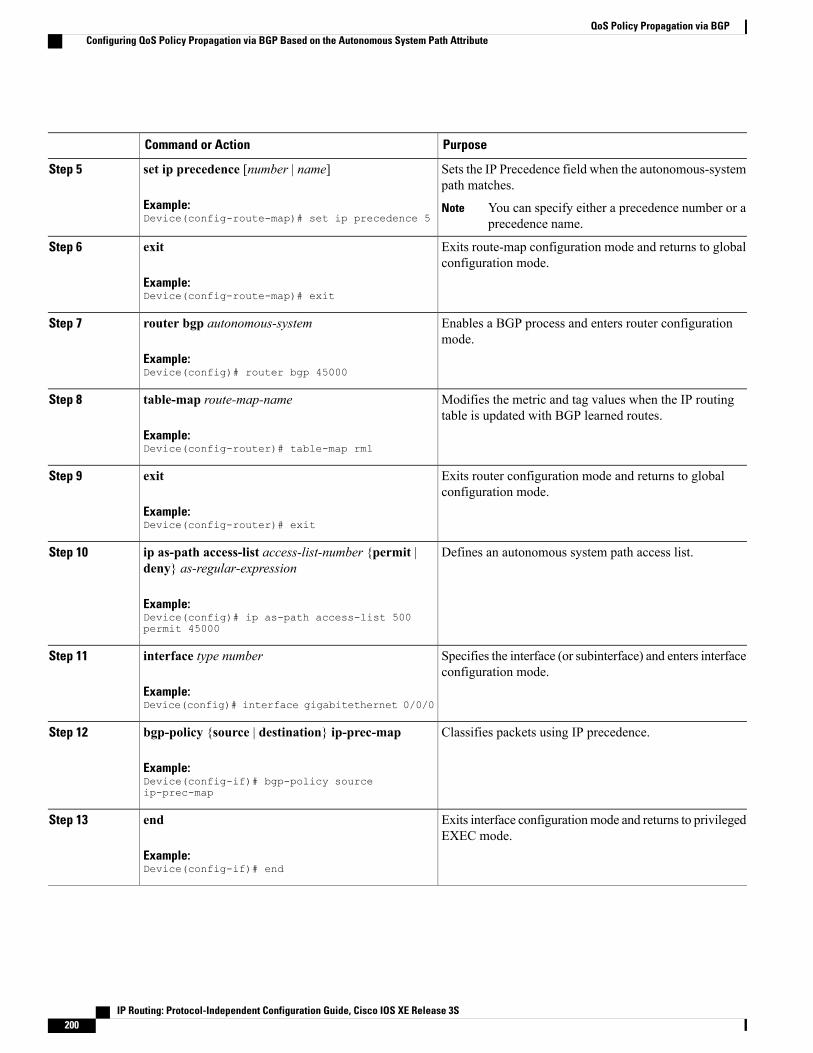
PurposeCommand or Action
Sets the IP Precedence field when the autonomous-systempath matches.
set ip precedence [number | name]
Example:Device(config-route-map)# set ip precedence 5
Step 5
You can specify either a precedence number or aprecedence name.
Note
Exits route-map configuration mode and returns to globalconfiguration mode.
exit
Example:Device(config-route-map)# exit
Step 6
Enables a BGP process and enters router configurationmode.
router bgp autonomous-system
Example:Device(config)# router bgp 45000
Step 7
Modifies the metric and tag values when the IP routingtable is updated with BGP learned routes.
table-map route-map-name
Example:Device(config-router)# table-map rm1
Step 8
Exits router configuration mode and returns to globalconfiguration mode.
exit
Example:Device(config-router)# exit
Step 9
Defines an autonomous system path access list.ip as-path access-list access-list-number {permit |deny} as-regular-expression
Step 10
Example:Device(config)# ip as-path access-list 500permit 45000
Specifies the interface (or subinterface) and enters interfaceconfiguration mode.
interface type number
Example:Device(config)# interface gigabitethernet 0/0/0
Step 11
Classifies packets using IP precedence.bgp-policy {source | destination} ip-prec-map
Example:Device(config-if)# bgp-policy sourceip-prec-map
Step 12
Exits interface configurationmode and returns to privilegedEXEC mode.
end
Example:Device(config-if)# end
Step 13
IP Routing: Protocol-Independent Configuration Guide, Cisco IOS XE Release 3S200
QoS Policy Propagation via BGPConfiguring QoS Policy Propagation via BGP Based on the Autonomous System Path Attribute

Configuring QoS Policy Propagation via BGP Based on an Access List
SUMMARY STEPS
1. enable2. configure terminal3. route-map route-map-name [permit | deny [sequence-number]]4. match ip address access-list-number5. set ip precedence [number | name]6. exit7. router bgp autonomous-system8. table-map route-map-name9. exit10. access-list access-list-number {permit | deny} source11. interface type number12. bgp-policy {source | destination} ip-prec-map13. end
DETAILED STEPS
PurposeCommand or Action
Enables privileged EXEC mode.enableStep 1
Example:
Device> enable
• Enter your password if prompted.
Enters global configuration mode.configure terminal
Example:
Device# configure terminal
Step 2
Defines a route map to control redistribution and entersroute-map configuration mode.
route-map route-map-name [permit | deny[sequence-number]]
Example:Device(config)# route-map rm1
Step 3
Matches an access list.match ip address access-list-number
Example:Device(config-route-map)# match ip address 69
Step 4
IP Routing: Protocol-Independent Configuration Guide, Cisco IOS XE Release 3S 201
QoS Policy Propagation via BGPConfiguring QoS Policy Propagation via BGP Based on an Access List
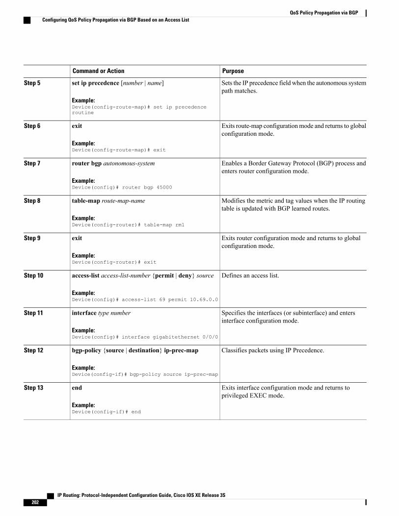
PurposeCommand or Action
Sets the IP precedence field when the autonomous systempath matches.
set ip precedence [number | name]
Example:Device(config-route-map)# set ip precedenceroutine
Step 5
Exits route-map configurationmode and returns to globalconfiguration mode.
exit
Example:Device(config-route-map)# exit
Step 6
Enables a Border Gateway Protocol (BGP) process andenters router configuration mode.
router bgp autonomous-system
Example:Device(config)# router bgp 45000
Step 7
Modifies the metric and tag values when the IP routingtable is updated with BGP learned routes.
table-map route-map-name
Example:Device(config-router)# table-map rm1
Step 8
Exits router configuration mode and returns to globalconfiguration mode.
exit
Example:Device(config-router)# exit
Step 9
Defines an access list.access-list access-list-number {permit | deny} source
Example:Device(config)# access-list 69 permit 10.69.0.0
Step 10
Specifies the interfaces (or subinterface) and entersinterface configuration mode.
interface type number
Example:Device(config)# interface gigabitethernet 0/0/0
Step 11
Classifies packets using IP Precedence.bgp-policy {source | destination} ip-prec-map
Example:Device(config-if)# bgp-policy source ip-prec-map
Step 12
Exits interface configuration mode and returns toprivileged EXEC mode.
end
Example:Device(config-if)# end
Step 13
IP Routing: Protocol-Independent Configuration Guide, Cisco IOS XE Release 3S202
QoS Policy Propagation via BGPConfiguring QoS Policy Propagation via BGP Based on an Access List
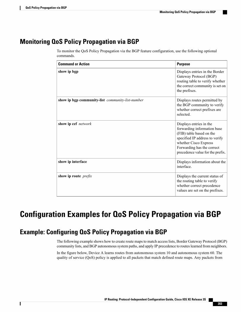
Monitoring QoS Policy Propagation via BGPTo monitor the QoS Policy Propagation via the BGP feature configuration, use the following optionalcommands.
PurposeCommand or Action
Displays entries in the BorderGateway Protocol (BGP)routing table to verify whetherthe correct community is set onthe prefixes.
show ip bgp
Displays routes permitted bythe BGP community to verifywhether correct prefixes areselected.
show ip bgp community-list community-list-number
Displays entries in theforwarding information base(FIB) table based on thespecified IP address to verifywhether Cisco ExpressForwarding has the correctprecedence value for the prefix.
show ip cef network
Displays information about theinterface.
show ip interface
Displays the current status ofthe routing table to verifywhether correct precedencevalues are set on the prefixes.
show ip route prefix
Configuration Examples for QoS Policy Propagation via BGP
Example: Configuring QoS Policy Propagation via BGPThe following example shows how to create route maps to match access lists, Border Gateway Protocol (BGP)community lists, and BGP autonomous system paths, and apply IP precedence to routes learned from neighbors.
In the figure below, Device A learns routes from autonomous system 10 and autonomous system 60. Thequality of service (QoS) policy is applied to all packets that match defined route maps. Any packets from
IP Routing: Protocol-Independent Configuration Guide, Cisco IOS XE Release 3S 203
QoS Policy Propagation via BGPMonitoring QoS Policy Propagation via BGP

Device A to autonomous system 10 or autonomous system 60 are sent the appropriate QoS policy, as thenumbered steps in the figure indicate.
Figure 8: Device Learning Routes and Applying QoS Policy
Device A Configuration
interface serial 5/0/0/1:0ip address 10.28.38.2 255.255.255.0bgp-policy destination ip-prec-mapno ip mroute-cacheno cdp enableframe-relay interface-dlci 20 IETFrouter bgp 30table-map precedence-mapneighbor 10.20.20.1 remote-as 10neighbor 10.20.20.1 send-community!ip bgp-community new-format!! Match community 1 and set the IP precedence to priorityroute-map precedence-map permit 10match community 1set ip precedence priority!! Match community 2 and set the IP precedence to immediateroute-map precedence-map permit 20match community 2set ip precedence immediate!! Match community 3 and set the IP precedence to flashroute-map precedence-map permit 30match community 3set ip precedence flash!! Match community 4 and set the IP precedence to flash-overrideroute-map precedence-map permit 40match community 4set ip precedence flash-override!! Match community 5 and set the IP precedence to criticalroute-map precedence-map permit 50match community 5set ip precedence critical!! Match community 6 and set the IP precedence to internetroute-map precedence-map permit 60match community 6set ip precedence internet!! Match community 7 and set the IP precedence to networkroute-map precedence-map permit 70match community 7set ip precedence network!
IP Routing: Protocol-Independent Configuration Guide, Cisco IOS XE Release 3S204
QoS Policy Propagation via BGPExample: Configuring QoS Policy Propagation via BGP

! Match ip address access list 69 or match autonomous system path 1! and set the IP precedence to criticalroute-map precedence-map permit 75match ip address 69match as-path 1set ip precedence critical!! For everything else, set the IP precedence to routineroute-map precedence-map permit 80set ip precedence routine!! Define community listsip community-list 1 permit 60:1ip community-list 2 permit 60:2ip community-list 3 permit 60:3ip community-list 4 permit 60:4ip community-list 5 permit 60:5ip community-list 6 permit 60:6ip community-list 7 permit 60:7!! Define the AS pathip as-path access-list 1 permit ^10_60!! Define the access listaccess-list 69 permit 10.69.0.0
Device B Configuration
router bgp 10neighbor 10.30.30.1 remote-as 30neighbor 10.30.30.1 send-communityneighbor 10.30.30.1 route-map send_community out!ip bgp-community new-format!! Match prefix 10 and set community to 60:1route-map send_community permit 10match ip address 10set community 60:1!! Match prefix 20 and set community to 60:2route-map send_community permit 20match ip address 20set community 60:2!! Match prefix 30 and set community to 60:3route-map send_community permit 30match ip address 30set community 60:3!! Match prefix 40 and set community to 60:4route-map send_community permit 40match ip address 40set community 60:4!! Match prefix 50 and set community to 60:5route-map send_community permit 50match ip address 50set community 60:5!! Match prefix 60 and set community to 60:6route-map send_community permit 60match ip address 60set community 60:6!! Match prefix 70 and set community to 60:7route-map send_community permit 70match ip address 70set community 60:7!! For all others, set community to 60:8
IP Routing: Protocol-Independent Configuration Guide, Cisco IOS XE Release 3S 205
QoS Policy Propagation via BGPExample: Configuring QoS Policy Propagation via BGP

route-map send_community permit 80set community 60:8!! Define access listsaccess-list 10 permit 10.61.0.0access-list 20 permit 10.62.0.0access-list 30 permit 10.63.0.0access-list 40 permit 10.64.0.0access-list 50 permit 10.65.0.0access-list 60 permit 10.66.0.0access-list 70 permit 10.67.0.0
Additional ReferencesRelated Documents
Document TitleRelated Topic
Cisco IOS Master Command List,All Releases
Cisco IOS commands
Cisco IOS IP Routing:Protocol-Independent CommandReference
IP routing protocol-independent commands
BGP Configuration GuideBGP configuration
Cisco Express ForwardingConfiguration Guide
Cisco Express Forwarding configuration
“Configuring Committed AccessRate” module in the QoS:Classification ConfigurationGuide(part of the Quality of ServiceSolutions Configuration GuideLibrary)
Committed access rate configuration
“Configuring Weighted RandomEarly Detection” module in theQoS: Congestion AvoidanceConfiguration Guide (part of theQuality of Service SolutionsConfiguration Guide Library)
Weighted Random Early Detection configuration
IP Routing: Protocol-Independent Configuration Guide, Cisco IOS XE Release 3S206
QoS Policy Propagation via BGPAdditional References
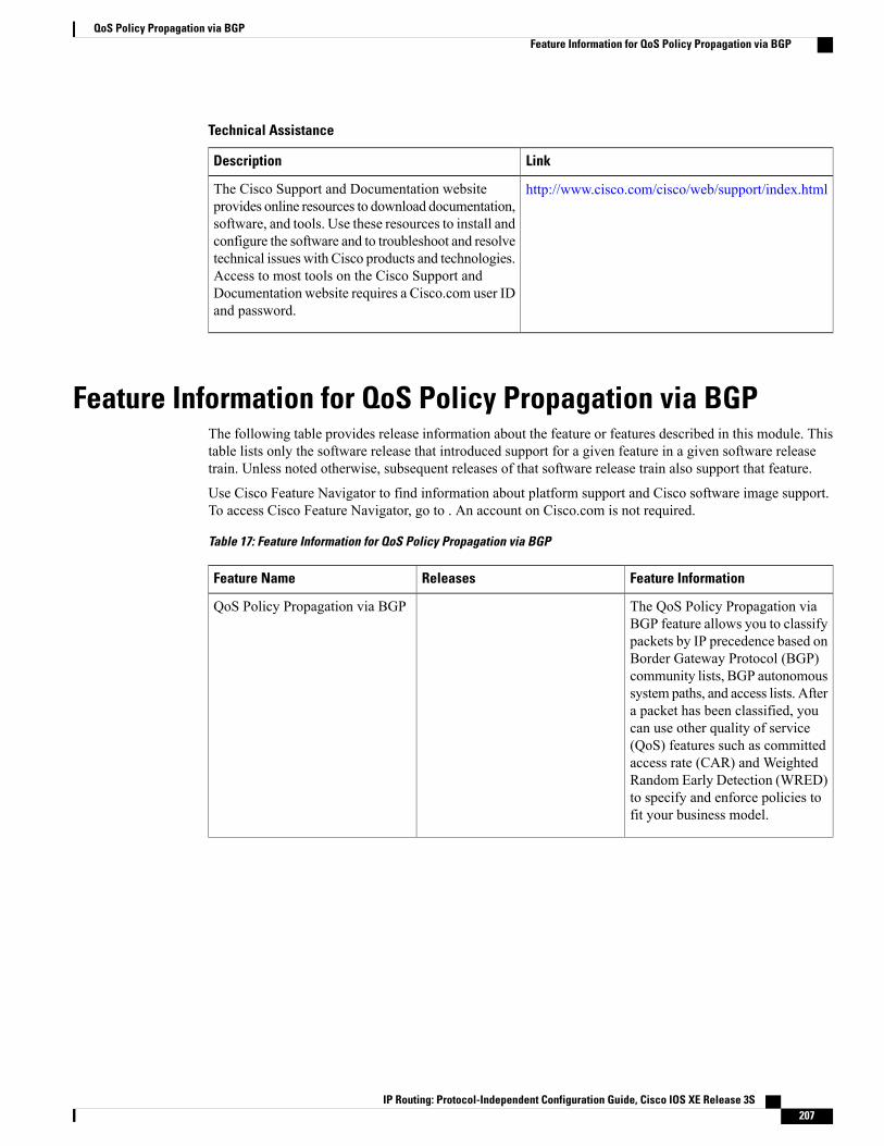
Technical Assistance
LinkDescription
http://www.cisco.com/cisco/web/support/index.htmlThe Cisco Support and Documentation websiteprovides online resources to download documentation,software, and tools. Use these resources to install andconfigure the software and to troubleshoot and resolvetechnical issues with Cisco products and technologies.Access to most tools on the Cisco Support andDocumentation website requires a Cisco.com user IDand password.
Feature Information for QoS Policy Propagation via BGPThe following table provides release information about the feature or features described in this module. Thistable lists only the software release that introduced support for a given feature in a given software releasetrain. Unless noted otherwise, subsequent releases of that software release train also support that feature.
Use Cisco Feature Navigator to find information about platform support and Cisco software image support.To access Cisco Feature Navigator, go to . An account on Cisco.com is not required.
Table 17: Feature Information for QoS Policy Propagation via BGP
Feature InformationReleasesFeature Name
The QoS Policy Propagation viaBGP feature allows you to classifypackets by IP precedence based onBorder Gateway Protocol (BGP)community lists, BGP autonomoussystem paths, and access lists. Aftera packet has been classified, youcan use other quality of service(QoS) features such as committedaccess rate (CAR) and WeightedRandom Early Detection (WRED)to specify and enforce policies tofit your business model.
QoS Policy Propagation via BGP
IP Routing: Protocol-Independent Configuration Guide, Cisco IOS XE Release 3S 207
QoS Policy Propagation via BGPFeature Information for QoS Policy Propagation via BGP

Feature InformationReleasesFeature Name
The Policy Routing Infrastructurefeature provides full support of IPpolicy-based routing with CiscoExpress Forwarding (CEF). AsCEF gradually obsoletes fastswitching, policy routing isintegrated with CEF to increasecustomer performancerequirements.When policy routingis enabled, redundant processing isavoided.
Policy Routing Infrastructure
IP Routing: Protocol-Independent Configuration Guide, Cisco IOS XE Release 3S208
QoS Policy Propagation via BGPFeature Information for QoS Policy Propagation via BGP

C H A P T E R 18NetFlow Policy Routing
NetFlow policy routing (NPR) integrates policy routing, which enables traffic engineering and trafficclassification, with NetFlow services, which provide billing, capacity planning, and information monitoringon real-time traffic flows. IP policy routing works with Cisco Express Forwarding (formerly known as CEF),distributed Cisco Express Forwarding (formerly known as dCEF), and NetFlow.
• Finding Feature Information, page 209
• Prerequisites for NetFlow Policy Routing, page 209
• Restrictions for NetFlow Policy Routing, page 210
• Information About NetFlow Policy Routing, page 210
• Additional References, page 211
• Feature Information for NetFlow Policy Routing, page 212
Finding Feature InformationYour software release may not support all the features documented in this module. For the latest caveats andfeature information, see Bug Search Tool and the release notes for your platform and software release. Tofind information about the features documented in this module, and to see a list of the releases in which eachfeature is supported, see the feature information table.
Use Cisco Feature Navigator to find information about platform support and Cisco software image support.To access Cisco Feature Navigator, go to www.cisco.com/go/cfn. An account on Cisco.com is not required.
Prerequisites for NetFlow Policy RoutingFor NetFlow policy routing to work, the following features must already be configured:
• Cisco Express Forwarding, distributed Cisco Express Forwarding, or NetFlow
• Policy routing
IP Routing: Protocol-Independent Configuration Guide, Cisco IOS XE Release 3S 209
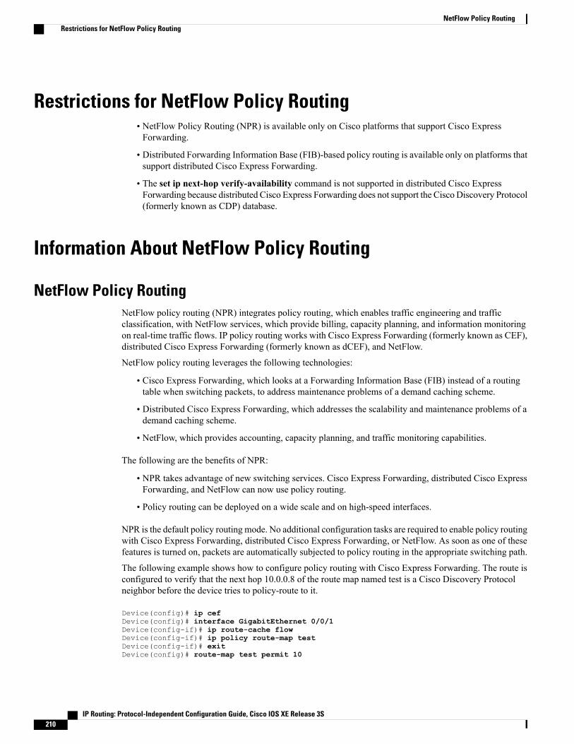
Restrictions for NetFlow Policy Routing• NetFlow Policy Routing (NPR) is available only on Cisco platforms that support Cisco ExpressForwarding.
• Distributed Forwarding Information Base (FIB)-based policy routing is available only on platforms thatsupport distributed Cisco Express Forwarding.
• The set ip next-hop verify-availability command is not supported in distributed Cisco ExpressForwarding because distributed Cisco Express Forwarding does not support the Cisco Discovery Protocol(formerly known as CDP) database.
Information About NetFlow Policy Routing
NetFlow Policy RoutingNetFlow policy routing (NPR) integrates policy routing, which enables traffic engineering and trafficclassification, with NetFlow services, which provide billing, capacity planning, and information monitoringon real-time traffic flows. IP policy routing works with Cisco Express Forwarding (formerly known as CEF),distributed Cisco Express Forwarding (formerly known as dCEF), and NetFlow.
NetFlow policy routing leverages the following technologies:
• Cisco Express Forwarding, which looks at a Forwarding Information Base (FIB) instead of a routingtable when switching packets, to address maintenance problems of a demand caching scheme.
• Distributed Cisco Express Forwarding, which addresses the scalability and maintenance problems of ademand caching scheme.
• NetFlow, which provides accounting, capacity planning, and traffic monitoring capabilities.
The following are the benefits of NPR:
• NPR takes advantage of new switching services. Cisco Express Forwarding, distributed Cisco ExpressForwarding, and NetFlow can now use policy routing.
• Policy routing can be deployed on a wide scale and on high-speed interfaces.
NPR is the default policy routing mode. No additional configuration tasks are required to enable policy routingwith Cisco Express Forwarding, distributed Cisco Express Forwarding, or NetFlow. As soon as one of thesefeatures is turned on, packets are automatically subjected to policy routing in the appropriate switching path.
The following example shows how to configure policy routing with Cisco Express Forwarding. The route isconfigured to verify that the next hop 10.0.0.8 of the route map named test is a Cisco Discovery Protocolneighbor before the device tries to policy-route to it.
Device(config)# ip cefDevice(config)# interface GigabitEthernet 0/0/1Device(config-if)# ip route-cache flowDevice(config-if)# ip policy route-map testDevice(config-if)# exitDevice(config)# route-map test permit 10
IP Routing: Protocol-Independent Configuration Guide, Cisco IOS XE Release 3S210
NetFlow Policy RoutingRestrictions for NetFlow Policy Routing

Device(config-route-map)# match ip address 1Device(config-route-map)# set ip precedence priorityDevice(config-route-map)# set ip next-hop 10.0.0.8Device(config-route-map)# set ip next-hop verify-availabilityDevice(config-route-map)# exitDevice(config)# route-map test permit 20Device(config-route-map)# match ip address 101Device(config-route-map)# set interface Ethernet 0/0/3Device(config-route-map)# set ip tos max-throughputDevice(config-route-map)# exit
Next-Hop ReachabilityYou can use the set ip next-hop verify-availability command to configure policy routing to verify thereachability of the next hop of a route map before the device performs policy routing to that next hop. Thiscommand has the following restrictions:
• It can cause performance degradation.
• Cisco Discovery Protocol must be enabled on the interface.
• The directly connected next hop must be a Cisco Discovery Protocol-enabled Cisco device.
• It does not work with distributed Cisco Express Forwarding configurations.
If a device is policy routing packets to the next hop and the next hop happens to be down, the device triesunsuccessfully to use the Address Resolution Protocol (ARP). This behavior can continue indefinitely. Youcan prevent this behavior by configuring the set ip next-hop verify availability command on the device. Thiscommand first verifies (using a route map) whether the next hop is a Cisco Discovery Protocol neighbor ofthe device before routing packets to that next hop. However, if you configure this command on a device whosenext hop is not a Cisco Discovery Protocol neighbor, the device looks at the subsequent next hop, if there isone. If there is no available next hop, packets are not policy-routed. This configuration is optional becausesome media or encapsulations do not support Cisco Discovery Protocol.
If the set ip next-hop verify availability command is not configured, packets are either policy-routed orremain forever unrouted.
If you want to verify the availability of only some next hops, you can configure different route-map entries(under the same route-map name) with different criteria (using access-list matching or packet-size matching),and use the set ip next-hop verify availability configuration command selectively.
Additional ReferencesRelated Documents
Document TitleRelated Topic
Cisco IOS Master Command List, All ReleasesCisco IOS commands
Cisco IOS IP Routing: Protocol-IndependentCommand Reference
IP routing protocol-independent commands
IP Routing: Protocol-Independent Configuration Guide, Cisco IOS XE Release 3S 211
NetFlow Policy RoutingNext-Hop Reachability
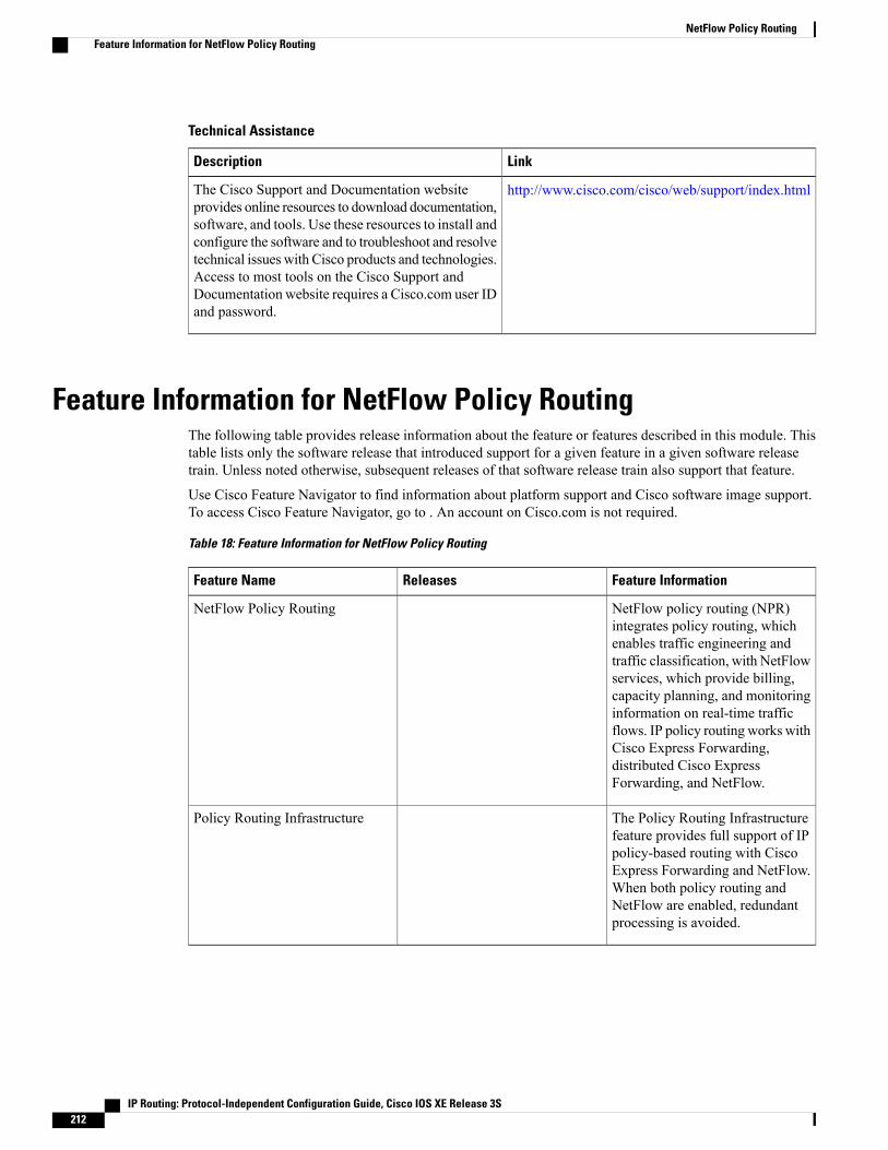
Technical Assistance
LinkDescription
http://www.cisco.com/cisco/web/support/index.htmlThe Cisco Support and Documentation websiteprovides online resources to download documentation,software, and tools. Use these resources to install andconfigure the software and to troubleshoot and resolvetechnical issues with Cisco products and technologies.Access to most tools on the Cisco Support andDocumentation website requires a Cisco.com user IDand password.
Feature Information for NetFlow Policy RoutingThe following table provides release information about the feature or features described in this module. Thistable lists only the software release that introduced support for a given feature in a given software releasetrain. Unless noted otherwise, subsequent releases of that software release train also support that feature.
Use Cisco Feature Navigator to find information about platform support and Cisco software image support.To access Cisco Feature Navigator, go to . An account on Cisco.com is not required.
Table 18: Feature Information for NetFlow Policy Routing
Feature InformationReleasesFeature Name
NetFlow policy routing (NPR)integrates policy routing, whichenables traffic engineering andtraffic classification, with NetFlowservices, which provide billing,capacity planning, and monitoringinformation on real-time trafficflows. IP policy routing works withCisco Express Forwarding,distributed Cisco ExpressForwarding, and NetFlow.
NetFlow Policy Routing
The Policy Routing Infrastructurefeature provides full support of IPpolicy-based routing with CiscoExpress Forwarding and NetFlow.When both policy routing andNetFlow are enabled, redundantprocessing is avoided.
Policy Routing Infrastructure
IP Routing: Protocol-Independent Configuration Guide, Cisco IOS XE Release 3S212
NetFlow Policy RoutingFeature Information for NetFlow Policy Routing
C H A P T E R 19Recursive Static Route
The Recursive Static Route feature enables you to install a recursive static route into the Routing InformationBase (RIB) even if the next-hop address of the static route or the destination network itself is already availablein the RIB as part of a previously learned route. This module explains recursive static routes and how toconfigure the Recursive Static Route feature.
• Finding Feature Information, page 213
• Restrictions for Recursive Static Route, page 213
• Information About Recursive Static Route, page 214
• How to Install Recursive Static Route, page 214
• Configuration Examples for Recursive Static Route, page 218
• Additional References for Recursive Static Route, page 219
• Feature Information for Recursive Static Routes, page 219
Finding Feature InformationYour software release may not support all the features documented in this module. For the latest caveats andfeature information, see Bug Search Tool and the release notes for your platform and software release. Tofind information about the features documented in this module, and to see a list of the releases in which eachfeature is supported, see the feature information table.
Use Cisco Feature Navigator to find information about platform support and Cisco software image support.To access Cisco Feature Navigator, go to www.cisco.com/go/cfn. An account on Cisco.com is not required.
Restrictions for Recursive Static RouteWhen recursive static routes are enabled using route maps, only one route map can be entered per virtualrouting and forwarding (VRF) instance or topology. If a second route map is entered, the new map willoverwrite the previous one.
IP Routing: Protocol-Independent Configuration Guide, Cisco IOS XE Release 3S 213

Information About Recursive Static Route
How to Install Recursive Static Route
Installing Recursive Static Routes in a VRFPerform these steps to install recursive static routes in a specific virtual routing and forwarding (VRF) instance.You can configure the recursive-static-route functionality on any number of VRFs. Installing recursive staticroutes in specific VRFs allows you to retain the default RIB behavior (of removing recursive static routes)for the rest of the network.
SUMMARY STEPS
1. enable2. configure terminal3. vrf definition vrf-name4. rd route-distinguisher5. address-family {ipv4 | ipv6}6. exit7. exit8. ip route [vrf vrf-name] prefix mask ip-address9. ip route static install-routes-recurse-via-nexthop [vrf vrf-name]10. end11. show running-config | include install12. show ip route vrf vrf-name
DETAILED STEPS
PurposeCommand or Action
Enables privileged EXEC mode.enableStep 1
Example:Device> enable
• Enter your password if prompted.
Enters global configuration mode.configure terminal
Example:Device# configure terminal
Step 2
Creates a virtual routing and forwarding (VRF) routingtable instance and enters VRF configuration mode.
vrf definition vrf-name
Example:Device(config)# vrf definition vrf1
Step 3
IP Routing: Protocol-Independent Configuration Guide, Cisco IOS XE Release 3S214
Recursive Static RouteInformation About Recursive Static Route
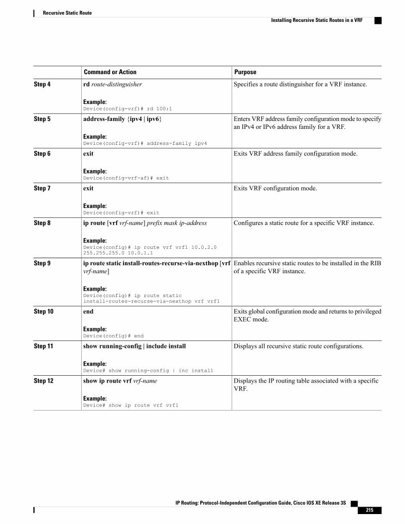
PurposeCommand or Action
Specifies a route distinguisher for a VRF instance.rd route-distinguisher
Example:Device(config-vrf)# rd 100:1
Step 4
Enters VRF address family configurationmode to specifyan IPv4 or IPv6 address family for a VRF.
address-family {ipv4 | ipv6}
Example:Device(config-vrf)# address-family ipv4
Step 5
Exits VRF address family configuration mode.exit
Example:Device(config-vrf-af)# exit
Step 6
Exits VRF configuration mode.exit
Example:Device(config-vrf)# exit
Step 7
Configures a static route for a specific VRF instance.ip route [vrf vrf-name] prefix mask ip-address
Example:Device(config)# ip route vrf vrf1 10.0.2.0255.255.255.0 10.0.1.1
Step 8
Enables recursive static routes to be installed in the RIBof a specific VRF instance.
ip route static install-routes-recurse-via-nexthop [vrfvrf-name]
Example:Device(config)# ip route staticinstall-routes-recurse-via-nexthop vrf vrf1
Step 9
Exits global configuration mode and returns to privilegedEXEC mode.
end
Example:Device(config)# end
Step 10
Displays all recursive static route configurations.show running-config | include install
Example:Device# show running-config | inc install
Step 11
Displays the IP routing table associated with a specificVRF.
show ip route vrf vrf-name
Example:Device# show ip route vrf vrf1
Step 12
IP Routing: Protocol-Independent Configuration Guide, Cisco IOS XE Release 3S 215
Recursive Static RouteInstalling Recursive Static Routes in a VRF

Installing Recursive Static Routes Using a Route MapPerform this task to install recursive static routes in a virtual routing and forwarding (VRF) instance definedby a route map. You can perform this task if you want to install recursive static routes for only a certain rangeof networks. If the route-map keyword is used without the vrf keyword, recursive static routes defined bythe route map will be applicable for the global VRF or topology.
SUMMARY STEPS
1. enable2. configure terminal3. vrf definition vrf-name4. rd route-distinguisher5. address-family {ipv4 | ipv6}6. exit7. exit8. ip route [vrf vrf-name] prefix mask ip-address9. access-list access-list-number permit source [source-wildcard]10. route-map map-tag11. match ip address access-list-number12. exit13. ip route static install-routes-recurse-via-nexthop [vrf vrf-name] [route-map map-name]14. end15. show running-config | include install16. show ip route vrf vrf-name
DETAILED STEPS
PurposeCommand or Action
Enables privileged EXEC mode.enableStep 1
Example:Device> enable
• Enter your password if prompted.
Enters global configuration mode.configure terminal
Example:Device# configure terminal
Step 2
Creates a virtual routing and forwarding (VRF) routingtable instance and enters VRF configuration mode.
vrf definition vrf-name
Example:Device(config)# vrf definition vrf1
Step 3
IP Routing: Protocol-Independent Configuration Guide, Cisco IOS XE Release 3S216
Recursive Static RouteInstalling Recursive Static Routes Using a Route Map
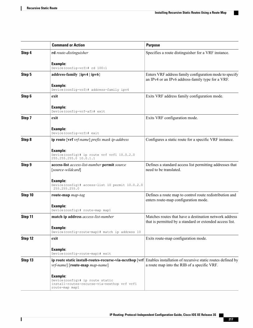
PurposeCommand or Action
Specifies a route distinguisher for a VRF instance.rd route-distinguisher
Example:Device(config-vrf)# rd 100:1
Step 4
Enters VRF address family configurationmode to specifyan IPv4 or an IPv6 address-family type for a VRF.
address-family {ipv4 | ipv6}
Example:Device(config-vrf)# address-family ipv4
Step 5
Exits VRF address family configuration mode.exit
Example:Device(config-vrf-af)# exit
Step 6
Exits VRF configuration mode.exit
Example:Device(config-vrf)# exit
Step 7
Configures a static route for a specific VRF instance.ip route [vrf vrf-name] prefix mask ip-address
Example:Device(config)# ip route vrf vrf1 10.0.2.0255.255.255.0 10.0.1.1
Step 8
Defines a standard access list permitting addresses thatneed to be translated.
access-list access-list-number permit source[source-wildcard]
Example:Device(config)# access-list 10 permit 10.0.2.0255.255.255.0
Step 9
Defines a route map to control route redistribution andenters route-map configuration mode.
route-map map-tag
Example:Device(config)# route-map map1
Step 10
Matches routes that have a destination network addressthat is permitted by a standard or extended access list.
match ip address access-list-number
Example:Device(config-route-map)# match ip address 10
Step 11
Exits route-map configuration mode.exit
Example:Device(config-route-map)# exit
Step 12
Enables installation of recursive static routes defined bya route map into the RIB of a specific VRF.
ip route static install-routes-recurse-via-nexthop [vrfvrf-name] [route-map map-name]
Example:Device(config)# ip route staticinstall-routes-recurse-via-nexthop vrf vrf1route-map map1
Step 13
IP Routing: Protocol-Independent Configuration Guide, Cisco IOS XE Release 3S 217
Recursive Static RouteInstalling Recursive Static Routes Using a Route Map
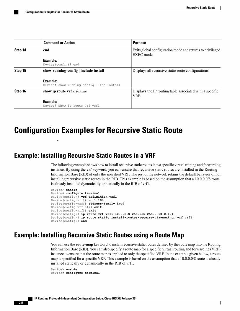
PurposeCommand or Action
Exits global configuration mode and returns to privilegedEXEC mode.
end
Example:Device(config)# end
Step 14
Displays all recursive static route configurations.show running-config | include install
Example:Device# show running-config | inc install
Step 15
Displays the IP routing table associated with a specificVRF.
show ip route vrf vrf-name
Example:Device# show ip route vrf vrf1
Step 16
Configuration Examples for Recursive Static Route•
Example: Installing Recursive Static Routes in a VRFThe following example shows how to install recursive static routes into a specific virtual routing and forwardinginstance. By using the vrf keyword, you can ensure that recursive static routes are installed in the RoutingInformation Base (RIB) of only the specified VRF. The rest of the network retains the default behavior of notinstalling recursive static routes in the RIB. This example is based on the assumption that a 10.0.0.0/8 routeis already installed dynamically or statically in the RIB of vrf1.Device> enableDevice# configure terminalDevice(config)# vrf definition vrf1Device(config-vrf)# rd 1:100Device(config-vrf)# address-family ipv4Device(config-vrf-af)# exitDevice(config-vrf)# exitDevice(config)# ip route vrf vrf1 10.0.2.0 255.255.255.0 10.0.1.1Device(config)# ip route static install-routes-recurse-via-nexthop vrf vrf1Device(config)# end
Example: Installing Recursive Static Routes using a Route MapYou can use the route-map keyword to install recursive static routes defined by the route map into the RoutingInformation Base (RIB). You can also specify a route map for a specific virtual routing and forwarding (VRF)instance to ensure that the route map is applied to only the specified VRF. In the example given below, a routemap is specified for a specific VRF. This example is based on the assumption that a 10.0.0.0/8 route is alreadyinstalled statically or dynamically in the RIB of vrf1.Device> enableDevice# configure terminal
IP Routing: Protocol-Independent Configuration Guide, Cisco IOS XE Release 3S218
Recursive Static RouteConfiguration Examples for Recursive Static Route

Device(config)# vrf definition vrf1Device(config-vrf)# rd 100:2Device(config-vrf)# address-family ipv4Device(config-vrf-af)# exitDevice(config-vrf)# exitDevice(config)# access-list 10 permit 10.0.2.0 255.255.255.0Device(config)# route-map map1Device(config-route-map)# match ip address 10Device(config-route-map)# exitDevice(config)# ip route static install-routes-recurse-via-nexthop vrf vrf1 route-map map1Device(config)# ip route vrf vrf1 10.0.2.0 255.255.255.0 10.0.1.1Device(config)# ip route vrf vrf1 10.0.3.0 255.255.255.0 10.0.1.1Device(config)# endIn the example above, route 10.0.2.0 255.255.255.0 10.0.1.1 will be installed in the RIB, but the route 10.0.3.0255. 255.255.0 10.0.1.1 will not be installed in the RIB because this route does not match the network definedin the route map.
Additional References for Recursive Static RouteRelated Documents
Document TitleRelated Topic
Cisco IOS Master Command List, All ReleasesCisco IOS commands
Cisco IOS IP Routing: Protocol-IndependentCommand Reference
IP routing protocol-independent commands
Technical Assistance
LinkDescription
http://www.cisco.com/cisco/web/support/index.htmlThe Cisco Support and Documentation websiteprovides online resources to download documentation,software, and tools. Use these resources to install andconfigure the software and to troubleshoot and resolvetechnical issues with Cisco products and technologies.Access to most tools on the Cisco Support andDocumentation website requires a Cisco.com user IDand password.
Feature Information for Recursive Static RoutesThe following table provides release information about the feature or features described in this module. Thistable lists only the software release that introduced support for a given feature in a given software releasetrain. Unless noted otherwise, subsequent releases of that software release train also support that feature.
Use Cisco Feature Navigator to find information about platform support and Cisco software image support.To access Cisco Feature Navigator, go to . An account on Cisco.com is not required.
IP Routing: Protocol-Independent Configuration Guide, Cisco IOS XE Release 3S 219
Recursive Static RouteAdditional References for Recursive Static Route

Table 19: Feature Information for Recursive Static Routes
Feature InformationReleasesFeature Name
The Recursive Static Route featureenables you to install a recursivestatic route into the RoutingInformation Base (RIB) even if thenext-hop address of the static routeor the destination network itself isalready available in the RIB as partof a previously learned route.
The following command wasintroduced: ip route staticinstall-recurse-via-nexthop.
Cisco IOS XE Release 3.9SRecursive Static Routes
IP Routing: Protocol-Independent Configuration Guide, Cisco IOS XE Release 3S220
Recursive Static RouteFeature Information for Recursive Static Routes