ip horn speaker ip-a1sc15 - toa
TRANSCRIPT
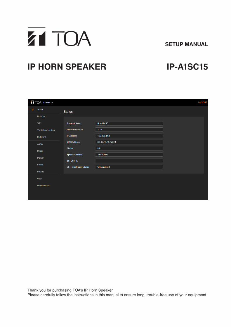
SETUP MANUAL
IP HORN SPEAKER IP-A1SC15
Thank you for purchasing TOA's IP Horn Speaker. Please carefully follow the instructions in this manual to ensure long, trouble-free use of your equipment.

2
TABLE OF CONTENTS
1. SETUP SUMMARY ........................................................................................... 4
2. SYSTEM REQUIREMENTS ........................................................................ 4
3. CONNECTION ..................................................................................................... 53.1. Connection Presets .............................................................................................. 53.2. Making Connection .............................................................................................. 5
4. SWITCHING SETUP SCREENS ............................................................ 64.1. Screen Contents .................................................................................................. 64.2. Logging Out .......................................................................................................... 7
5. STATUS SCREEN DISPLAY ...................................................................... 8
6. NETWORK SETTINGS SCREEN ........................................................... 96.1. Display Contents .................................................................................................. 96.2. Saving Settings & Changes ............................................................................... 10
7. SIP SETTINGS SCREEN ............................................................................ 117.1. Display Contents ................................................................................................ 117.2. Saving Settings & Changes ................................................................................ 12
8. VMS BROADCASTING SETTINGS SCREEN .............................. 138.1. Display Contents ................................................................................................ 138.2. Saving Settings & Changes .............................................................................. 14
9. MULTICAST SETTINGS SCREEN ....................................................... 159.1. Display Contents ................................................................................................ 159.2. Saving Settings & Changes .............................................................................. 16
10. AUDIO SETTINGS SCREEN ................................................................. 1710.1. Display Contents .............................................................................................. 1710.2. Saving Settings & Changes ............................................................................ 1810.3. Conceptual Diagram of the Sound Volume Settings Function ......................... 18
11. MEDIA SETTING SCREEN ................................................................... 1911.1. Display Contents .............................................................................................. 1911.2. Uploading Sound Source Files ......................................................................... 2011.3. Downloading Sound Source Files .................................................................... 2011.4. Deleting Sound Source Files ............................................................................ 21
12. PATTERN REGISTRATION SCREEN ............................................. 2212.1. Display Contents ............................................................................................... 2212.2. Performing Broadcast Tests ............................................................................. 2312.3. Saving Settings & Changes ............................................................................ 24
13. EVENT SETTINGS SCREEN ................................................................ 2513.1. Display Contents .............................................................................................. 2513.2. Saving Settings & Changes ............................................................................ 26
3
14. PRIORITY BROADCAST SETTINGS .............................................. 2714.1. Display Contents ............................................................................................... 2714.2. Saving Settings & Changes ............................................................................ 28
15. USER SETTINGS SCREEN ................................................................... 2915.1. Display Contents .............................................................................................. 2915.2. Saving Settings & Changes ............................................................................ 30
16. MAINTENANCE SCREEN ...................................................................... 3116.1. Display Contents ............................................................................................... 3116.2. Downloading Settings Data ............................................................................. 3216.3. Uploading Settings Data ................................................................................. 3316.4. Initialization of Settings .................................................................................... 3416.5. Factory Default Settings ................................................................................... 3516.6. Firmware Update .............................................................................................. 3516.7. Restarting the Unit ............................................................................................ 36
17. STATUS INDICATOR OPERATION ................................................... 37
18. IP SETTING TOOL ...................................................................................... 3818.1. Before Using: .................................................................................................... 3818.2. Starting the IP Setting Tool .............................................................................. 3818.3. Setting Method ................................................................................................. 3918.4. User Authentication .......................................................................................... 4118.5. Network Settings .............................................................................................. 4118.6. Uploading Settings Files .................................................................................. 4418.7. Downloading Settings Files .............................................................................. 4518.8. Firmware Update .............................................................................................. 4618.9. Restarting the Unit ........................................................................................... 47
19. USABLE CHARACTERS ......................................................................... 4819.1. Characters That Can Be Used for Names, Authentication ID and Passwords ................................................................................................. 4819.2. Characters That Can Be Used for Filenames .................................................. 48

4
1. SETUP SUMMARYConnecting a PC to the IP-A1SC15 IP Horn Speaker (hereinafter referred to as the "unit") by way of a browser* allows the following settings, displays and the like to be made via a network.* For recommended browsers, please refer to "SYSTEM REQUIREMENTS" below.
• Status Display• Network Settings• SIP Settings• VMS Broadcasting Settings• Multicast Settings• Audio Settings• Media Settings• Pattern Settings• Event Settings• Priority Broadcast Settings• User Settings• Maintenance
2. SYSTEM REQUIREMENTSRecommended PC operation environments are as follows:
OS Windows 10 Pro (64bit)Windows 10 Home (64bit)
Browser Microsoft Edge Google Chrome
Notes• Microsoft Edge is the registered trademark of Microsoft Corporation in the United States and other countries.• Google Chrome is the trademark of Google LLC in the United States and other countries.

5
3. CONNECTION3.1. Connection Presets
The unit is factory-preset as follows:Username: adminPassword: guestIP address: 192.168.14.1Subnet mask: 255.255.255.0Default gateway: 192.168.14.254
Before connecting a PC to the IP horn speaker and changing its setting, it will be necessary to set the PC's network settings so that it can operate on the same network as the IP horn speaker. Take care that no IP addresses are duplicated in the same network. For example, if the IP horn speaker's IP address is 192.168.14.1, set the PC's IP address to 192.168.14.10 or the like.
3.2. Making Connection
Notes• Avoid simultaneously connecting to the IP horn speaker from multiple PCs.• Avoid simultaneously connecting to the IP horn speaker from a single PC using multiple browsers.
Step 1. Connect both the unit and the PC to be used for setup to the network.
Step 2. Start the PC's browser and enter the unit's IP address in the address field.Example: 192.168.14.1The Login screen will be displayed.
TipDefault IP address: 192.168.14.1
Step 3. Enter both the username and the password, and click on the LOGIN button. The Status screen will be displayed. Click on the individual function names arranged on the left side of the browser screen to switch screens and perform the required settings for each selected screen.
3
6
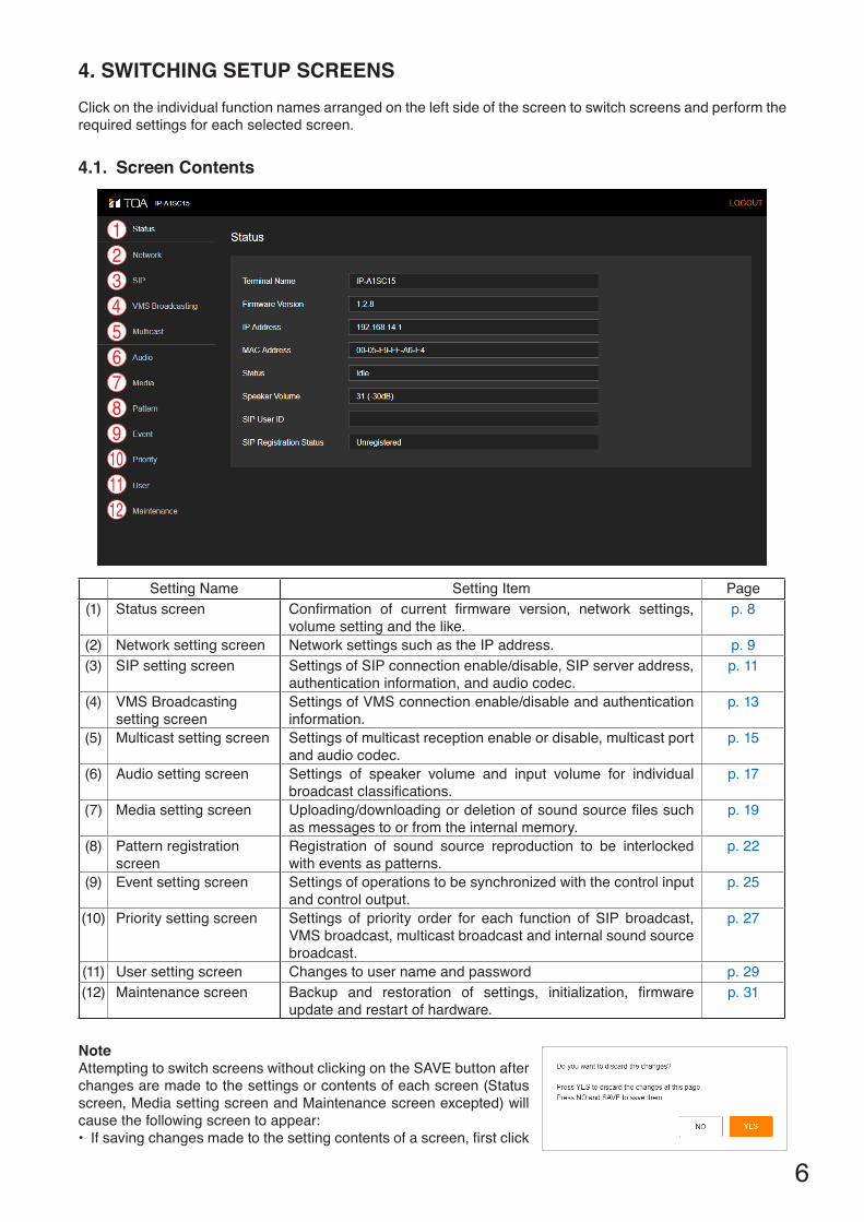
4. SWITCHING SETUP SCREENS Click on the individual function names arranged on the left side of the screen to switch screens and perform the required settings for each selected screen.
4.1. Screen Contents
Setting Name Setting Item Page(1) Status screen Confirmation of current firmware version, network settings,
volume setting and the like.p. 8
(2) Network setting screen Network settings such as the IP address. p. 9(3) SIP setting screen Settings of SIP connection enable/disable, SIP server address,
authentication information, and audio codec.p. 11
(4) VMS Broadcasting setting screen
Settings of VMS connection enable/disable and authentication information.
p. 13
(5) Multicast setting screen Settings of multicast reception enable or disable, multicast port and audio codec.
p. 15
(6) Audio setting screen Settings of speaker volume and input volume for individual broadcast classifications.
p. 17
(7) Media setting screen Uploading/downloading or deletion of sound source files such as messages to or from the internal memory.
p. 19
(8) Pattern registration screen
Registration of sound source reproduction to be interlocked with events as patterns.
p. 22
(9) Event setting screen Settings of operations to be synchronized with the control input and control output.
p. 25
(10) Priority setting screen Settings of priority order for each function of SIP broadcast, VMS broadcast, multicast broadcast and internal sound source broadcast.
p. 27
(11) User setting screen Changes to user name and password p. 29(12) Maintenance screen Backup and restoration of settings, initialization, firmware
update and restart of hardware.p. 31
NoteAttempting to switch screens without clicking on the SAVE button after changes are made to the settings or contents of each screen (Status screen, Media setting screen and Maintenance screen excepted) will cause the following screen to appear:• If saving changes made to the setting contents of a screen, first click
123456789101112
7
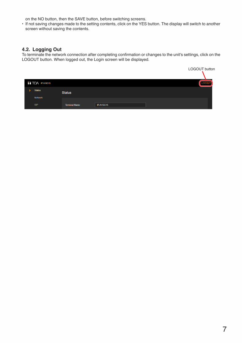
4.2. Logging OutTo terminate the network connection after completing confirmation or changes to the unit's settings, click on the LOGOUT button. When logged out, the Login screen will be displayed.
LOGOUT button
on the NO button, then the SAVE button, before switching screens.• If not saving changes made to the setting contents, click on the YES button. The display will switch to another
screen without saving the contents.

8
5. STATUS SCREEN DISPLAYThis screen displays the unit's current main setting contents, etc. Since this page only displays the current settings, the contents cannot be changed on this page.
Item Contents(1) Terminal Name Displays the device name set on the Network settings screen (p. 9). (2) Firmware Version Displays the unit's current firmware version. (See "Firmware Update" on p. 46)(3) IP Address Displays the unit's IP address set on the Network settings screen (p. 9). (4) MAC Address Displays the unit's MAC address. (5) Status Displays the unit's operating status.
Idle: Standby stateSIP Calling: Call to an SIP device in progressSIP: SIP broadcast in progressVMS Broadcasting: VMS broadcast in progressMulticast 1 – 10: Multicasts 1 – 10 in progressPattern 1 – 20 (xxxxxxx)*: Broadcasts of internal sound source files 1 – 20
in progress* Sound source filename is displayed in parentheses ( ).
(6) Speaker Volume Displays the speaker volume set on the Audio settings screen (p. 17). (7) SIP User ID Displays the unit's name when registering the unit on the SIP server. (See "SIP
SETTINGS SCREEN" on p. 11.)(8) SIP Registration
StatusDisplays the unit's registration status when registering it on a SIP server. (See "SIP SETTINGS SCREEN" on p. 11.)
Registered: Registration successful.Registration Failed: Registration failed.Registering: Registration in progress.Unregistered: Registration invalid.
12345678

9
6. NETWORK SETTINGS SCREENThe unit's network-related settings are performed on this screen.
6.1. Display Contents
Item Contents(1) Terminal Name Set the unit's terminal name.
Initial setting: IP-A1SC15Tips• For usable characters, please refer to "USABLE CHARACTERS" on p. 48.• Max: 31 characters
(2) IP Address Set the unit's IP address.Initial setting: 192.168.14.1
(3) Subnet Mask Set the unit's subnet mask.Initial setting: 255.255.255.0
(4) Default Gateway Set the unit's default gateway.Initial setting: 192.168.14.254
(5) SAVE button Click to save the settings and changes. (See "Saving Settings & Changes" on p. 10.)
1234
5

10
6.2. Saving Settings & Changes
When all settings or changes are completed, save their contents.
Step 1. Click on the SAVE button.The dialog box, "Do you want to discard the changes?" is displayed.
Step 2. Click on the OK button.
NoteThe set or changed contents on this screen will not be in effect until the unit has restarted. To restart the unit, click on the REBOOT button on the Maintenance screen. (See "Restarting the Unit" on p. 36.)

11
7. SIP SETTINGS SCREENPerform all settings related to SIP connections.
7.1. Display Contents
Item Contents(1) SIP Account Active Click on the button to select whether or not to use the SIP server registration
function.If using: ONIf not using: OFF
(2) SIP Server Address Set the SIP server's IP address and port number.Initial setting: IP address: 0.0.0.0, Port No.: 5060The SIP registration status is displayed at right.
Registered: Registration successful.Registration Failed: Registration failed.Registering: Registration in progress.Unregistered: Registration invalid.
(3) Registration Expiry Set the unit's SIP server registration expiry period. Set the same value as the registration authentication expiry preset for the SIP server (unit: sec).Setting range: 60 – 7200Initial setting: 1800
(4) User ID* Set the unit's name needed when registering the unit on the SIP server. Initial setting: Blank
(5) Display Name* Set the name to be displayed on the destination terminal when the unit establishes an SIP connection to that terminal.The display name may be the same as the User ID (4).Initial setting: IP-A1SC15
1234567
8
910
11
12
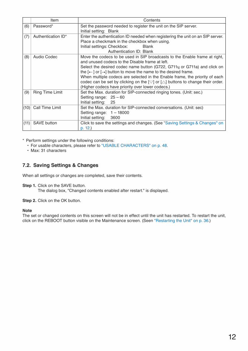
Item Contents(6) Password* Set the password needed to register the unit on the SIP server.
Initial setting: Blank(7) Authentication ID* Enter the authentication ID needed when registering the unit on an SIP server.
Place a checkmark in the checkbox when using. Initial settings: Checkbox: Blank Authentication ID: Blank
(8) Audio Codec Move the codecs to be used in SIP broadcasts to the Enable frame at right, and unused codecs to the Disable frame at left. Select the desired codec name button (G722, G711ɥ or G711a) and click on the [ ] or [ ] button to move the name to the desired frame. When multiple codecs are selected in the Enable frame, the priority of each codec can be set by clicking on the [ ] or [ ] buttons to change their order. (Higher codecs have priority over lower codecs.)
(9) Ring Time Limit Set the Max. duration for SIP-connected ringing tones. (Unit: sec.)Setting range: 25 – 60Initial setting: 25
(10) Call Time Limit Set the Max. duration for SIP-connected conversations. (Unit: sec)Setting range: 1 – 18000Initial setting: 3600
(11) SAVE button Click to save the settings and changes. (See "Saving Settings & Changes" on p. 12.)
* Perform settings under the following conditions:• For usable characters, please refer to "USABLE CHARACTERS" on p. 48.• Max: 31 characters
7.2. Saving Settings & Changes
When all settings or changes are completed, save their contents.
Step 1. Click on the SAVE button.The dialog box, "Changed contents enabled after restart." is displayed.
Step 2. Click on the OK button.
NoteThe set or changed contents on this screen will not be in effect until the unit has restarted. To restart the unit, click on the REBOOT button visible on the Maintenance screen. (Seen "Restarting the Unit" on p. 36.)
13
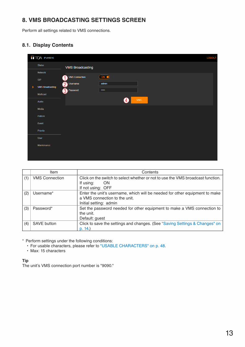
8. VMS BROADCASTING SETTINGS SCREENPerform all settings related to VMS connections.
8.1. Display Contents
Item Contents(1) VMS Connection Click on the switch to select whether or not to use the VMS broadcast function.
If using: ONIf not using: OFF
(2) Username* Enter the unit's username, which will be needed for other equipment to make a VMS connection to the unit.Initial setting: admin
(3) Password* Set the password needed for other equipment to make a VMS connection to the unit. Default: guest
(4) SAVE button Click to save the settings and changes. (See "Saving Settings & Changes" on p. 14.)
* Perform settings under the following conditions:• For usable characters, please refer to "USABLE CHARACTERS" on p. 48.• Max: 15 characters
TipThe unit’s VMS connection port number is "9090."
123
4
14
8.2. Saving Settings & Changes
When all settings or changes are completed, save their contents.
Step 1. Click on the SAVE button.The dialog box, "Changed contents enabled after restart." is displayed.
Step 2. Click on the OK button.
NoteThe set or changed contents on this screen will not be in effect until the unit has restarted. To restart the unit, click on the REBOOT button visible on the Maintenance screen. (See "Restarting the Unit" on p. 36.)
15
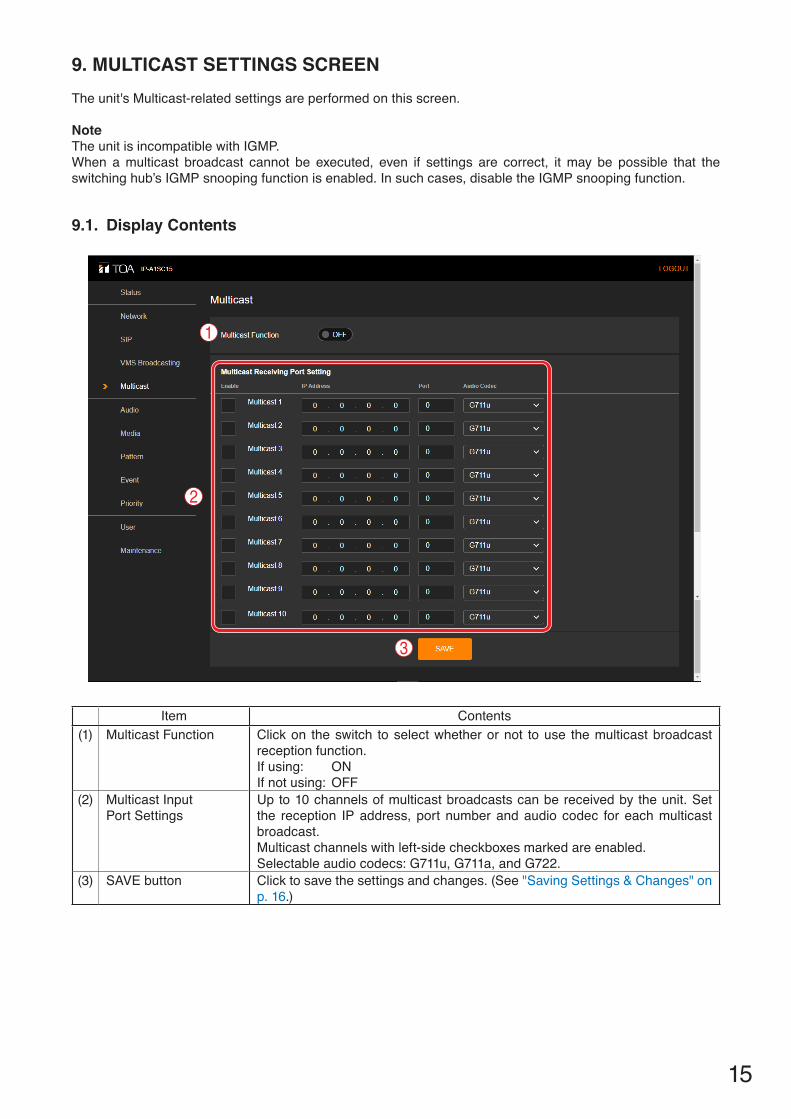
9. MULTICAST SETTINGS SCREENThe unit's Multicast-related settings are performed on this screen.
NoteThe unit is incompatible with IGMP. When a multicast broadcast cannot be executed, even if settings are correct, it may be possible that the switching hub’s IGMP snooping function is enabled. In such cases, disable the IGMP snooping function.
9.1. Display Contents
Item Contents(1) Multicast Function Click on the switch to select whether or not to use the multicast broadcast
reception function.If using: ONIf not using: OFF
(2) Multicast InputPort Settings
Up to 10 channels of multicast broadcasts can be received by the unit. Set the reception IP address, port number and audio codec for each multicast broadcast.Multicast channels with left-side checkboxes marked are enabled.Selectable audio codecs: G711u, G711a, and G722.
(3) SAVE button Click to save the settings and changes. (See "Saving Settings & Changes" on p. 16.)
1
2
3

16
9.2. Saving Settings & Changes
When all settings or changes are completed, save their contents.
Step 1. Click on the SAVE button.The dialog box, "Changed contents enabled after restart." is displayed.
Step 2. Click on the OK button.
Note:The set or changed contents on this screen will not be in effect until the unit has restarted. To restart the unit, click on the REBOOT button visible on the Maintenance screen. (See "Restarting the Unit" on p. 36.)

17
10. AUDIO SETTINGS SCREENThe speaker's master volume and correction volume are set for each broadcast using this screen.
10.1. Display Contents
(1) Speaker VolumeAdjust the speaker's broadcasting volume.
Item ContentsA Speaker Mute Mark the checkbox to mute speaker sound output.
Uncheck the checkbox to disable muting.B Master Volume* Click on the [ ] mark to select the appropriate speaker volume from the
pulldown menu.Setting range: 0 (mute) – 61 (0 dB)Initial setting: 31 (−30 dB)
C Offset Volume* Displays the set value of offset volume correction to the Master Volume. Offset volume correction is set remotely by external equipment and cannot be adjusted using the browser.Setting range: −20 to +20 dBInitial setting: 0 dB
* Actual speaker broadcasting volume is determined by the sum of the Master Volume and Offset Volume settings.
1
2
3
ABC
DE
F
18
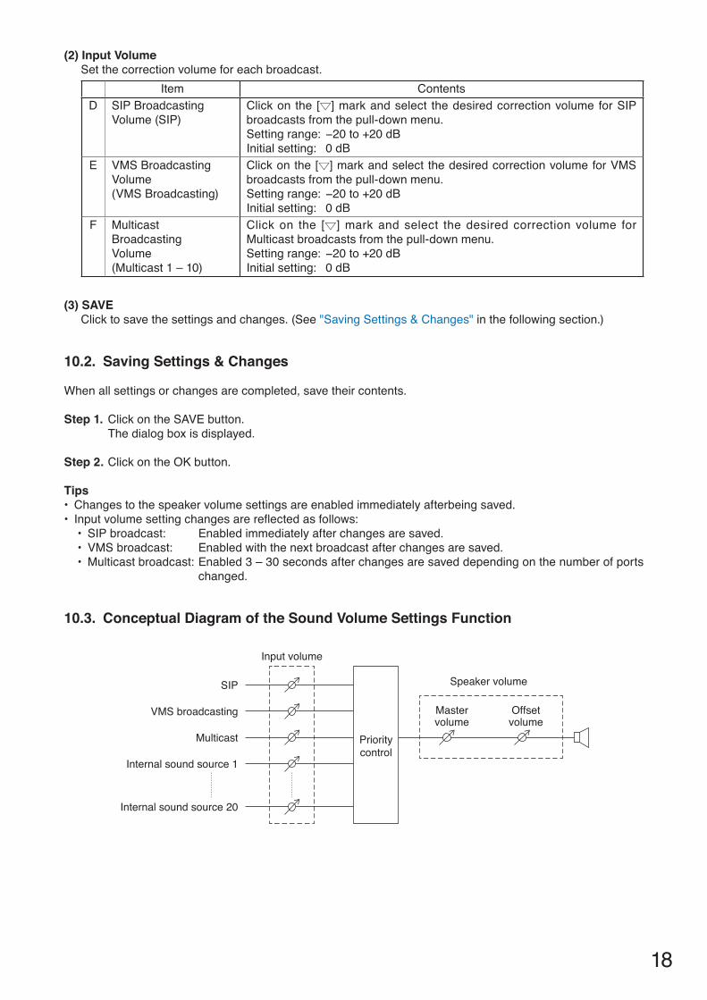
(2) Input VolumeSet the correction volume for each broadcast.
Item ContentsD SIP Broadcasting
Volume (SIP)Click on the [ ] mark and select the desired correction volume for SIP broadcasts from the pull-down menu.Setting range: −20 to +20 dBInitial setting: 0 dB
E VMS BroadcastingVolume (VMS Broadcasting)
Click on the [ ] mark and select the desired correction volume for VMS broadcasts from the pull-down menu.Setting range: −20 to +20 dBInitial setting: 0 dB
F MulticastBroadcastingVolume(Multicast 1 – 10)
Click on the [ ] mark and select the desired correction volume for Multicast broadcasts from the pull-down menu.Setting range: −20 to +20 dBInitial setting: 0 dB
(3) SAVEClick to save the settings and changes. (See "Saving Settings & Changes" in the following section.)
10.2. Saving Settings & Changes
When all settings or changes are completed, save their contents.
Step 1. Click on the SAVE button.The dialog box is displayed.
Step 2. Click on the OK button.
Tips• Changes to the speaker volume settings are enabled immediately afterbeing saved.• Input volume setting changes are reflected as follows:
• SIP broadcast: Enabled immediately after changes are saved.• VMS broadcast: Enabled with the next broadcast after changes are saved.• Multicast broadcast: Enabled 3 – 30 seconds after changes are saved depending on the number of ports
changed.
10.3. Conceptual Diagram of the Sound Volume Settings Function
Input volume
SIP
VMS broadcasting
Multicast
Internal sound source 1
Internal sound source 20
Prioritycontrol
Speaker volume
Mastervolume
Offsetvolume
19
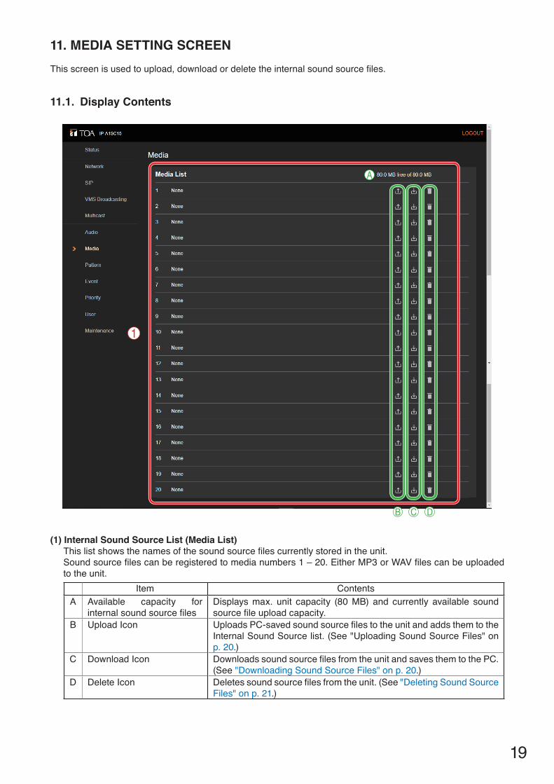
11. MEDIA SETTING SCREEN This screen is used to upload, download or delete the internal sound source files.
11.1. Display Contents
(1) Internal Sound Source List (Media List)This list shows the names of the sound source files currently stored in the unit. Sound source files can be registered to media numbers 1 – 20. Either MP3 or WAV files can be uploaded to the unit.
Item ContentsA Available capacity for
internal sound source filesDisplays max. unit capacity (80 MB) and currently available sound source file upload capacity.
B Upload Icon Uploads PC-saved sound source files to the unit and adds them to the Internal Sound Source list. (See "Uploading Sound Source Files" on p. 20.)
C Download Icon Downloads sound source files from the unit and saves them to the PC. (See "Downloading Sound Source Files" on p. 20.)
D Delete Icon Deletes sound source files from the unit. (See "Deleting Sound Source Files" on p. 21.)
1
A
B C D

20
11.2. Uploading Sound Source Files
Follow the procedure below to upload sound source files to the unit:Max. sound source file storage capacity is 30 MB per file and 80 MB total.Supported file formats are as follows:
WAV file: 8/16/44.1/48 kHz sampling frequency, 8/16 bit, monaural/stereoMP3 file: 32/44.1/48 kHz sampling frequency, 64 to 320 kbps, CBR/VBR, monaural/stereo
Notes• There are restrictions on the types of characters that can be used for filenames. Files that do not meet these
conditions cannot be used. Upload the file after changing the filename to one that consists of only usable characters, referring to "USABLE CHARACTERS" on p. 48.
• If sound source files are uploaded while an internal sound source broadcast is in progress, the broadcast will stop.
TipSound source file format and file size are roughly indicated as follows:
Sound source file format File size per minute Total saveable time (for 80 MB)WAV (monaural, 48 kHz, 16 bit) 5.8 MB About 14 minutesWAV (monaural, 44.1 kHz, 16 bit) 5.3 MB About 15 minutesWAV (monaural, 44.1 kHz, 8 bit) 2.6 MB About 30 minutesMP3 (monaural, 320 kbps) 2.4 MB About 33 minutesMP3 (monaural, 256 kbps) 1.9 MB About 42 minutesMP3 (monaural, 192 kbps) 1.4 MB About 56 minutesMP3 (monaural, 128 kbps) 1.0 MB About 83 minutes
Note that the above times are only provided as a guide. Total times may be shorter than those indicated, depending on the recording device or the data creation method.
Step 1. Click on the Upload icon to the right of the media number to be saved. The file explorer opens.
Step 2. Select the sound source file to be uploaded to the unit.
Step 3. Click on the OK button. Upload begins.Following upload completion, the new sound source filename is added to the displayed Internal Sound Source list.
11.3. Downloading Sound Source Files
Follow the procedure below to download sound source files:
Step 1. Click on the Download icon to the right of the media number to be saved to the PC.The file explorer opens.
Step 2. Select the folder where the file will be saved.
Step 3. Click on the OK button.

21
The selected sound source file is downloaded.
11.4. Deleting Sound Source Files
Follow the procedure below to delete sound source files:
NoteIf sound source files are deleted while an internal sound source broadcast is in progress, the broadcast will stop.
Step 1. Click on the Delete icon to the right of the media number to be deleted.The dialog box is displayed.
Step 2. Click on the YES button.The selected sound source file is deleted.

22
12. PATTERN REGISTRATION SCREENUp to 20 internal sound source files can be registered as a broadcast pattern for broadcast in synchronization with specific events.
12.1. Display Contents
Item Contents(1) Pattern List Up to 20 internal sound source files can be registered to each broadcast
pattern. Clicking on a pattern activates it for the registration of sound source files, which can be selected on the right side of the screen.
(2) Pattern Name Assigns a name to each pattern.Tips• For usable characters, please refer to "USABLE CHARACTERS" on p. 48.• Max: 15 characters.
(3) Media Files(Internal sound source files)
Select the internal sound source files to be broadcast in each pattern.
(4) Play Count(No. of repeatsof broadcast)
Set the number of times a broadcast of selected internal sound source files will be repeated.Setting range: 1 – 10 repetitionsInitial setting: 1 repeat
(5) Interval(Interval betweenbroadcasts)
Set the time interval (in sec.) between repeated broadcasts of internal sound source files. Setting range: 0 – 30 sec. Initial setting: 3 sec.
1
2
3
4
5
67
8 9
10

23
Item Contents(6) Offset Volume The offset volume can be set to equalize the sound output of individual patterns
or change the output level for each pattern.Changes to the offset volume settings are enabled from the next broadcast after such changes are saved.Setting range: −20 to +20 dBInitial setting: 0 dB
(7) Control-out(Control output button)
Connected external equipment can be controlled by transmitting a signal from the control output during broadcasts of internal sound source files. If the checkbox at right is marked, the external control output turns ON when the unit begins broadcasting internal sound source files, and turns OFF when the broadcast is stopped.
(8) PLAY button Click to start the test broadcast of a broadcast pattern. (Refer to the following section, Performing Broadcast Tests.)
(9) STOP button Click to stop the test broadcast of the broadcast pattern.(Refer to the following section, Performing Broadcast Tests.)
(10) SAVE button Click to save the settings and changes. (See "Saving Settings & Changes" on p. 24.)
12.2. Performing Broadcast Tests
Follow the procedure below to conduct broadcast tests for selected broadcast patterns:
NoteNeither the PLAY nor STOP buttons can be used if the set contents have not yet been saved.
Step 1. Click and select the broadcast pattern to be tested.
Step 2. Click on the PLAY button.A test broadcast of the selected broadcast pattern will begin.
Step 3. Click on the STOP button to stop the test.The test broadcast stops.
1
2 3
24
12.3. Saving Settings & Changes
When all settings or changes are completed, save their contents.
Step 1. Click on the SAVE button.The dialog box is displayed.
Step 2. Click on the OK button.
NoteSettings and changes performed on this screen are enabled immediately after being saved.However, any changes to the offset volume settings are only reflected beginning with the next broadcast after they are saved.

25
13. EVENT SETTINGS SCREENPerform all settings related to contact control input and output.
13.1. Display Contents
(1) Control-in Broadcasts can be initiated by control signals received from connected external equipment. Each of the 2 control inputs can be independently assigned which broadcast to execute.
Item ContentsA Action Click on the [ ] button to select the function to be executed when a signal
is received at Control Input from an external device.None: Disables Control Input 1 or 2.Pattern 1 – 20: Broadcast the internal sound source file assigned to the
pattern.SIP1, SIP2: Make SIP calls to the destination terminals corresponding
to the IP addresses or SIP user IDs set in the Target fields of SIP 1 and SIP 2 (D).
B Signal Mode Click on the [ ] button to select the signal mode.Level: Only executes the designated broadcast pattern for the period of
time that input remains enabled, stopping the broadcast when input is terminated.
Edge: Executes the designated broadcast pattern when the input is enabled, and continues with the broadcast even after the input is terminated.
NoteIf SIP1 or SIP2 is selected in Action (A), only the Edge signal mode can be selected.
C State Click on the [ ] button to select the signal status.Normally Open: The control input turns OFF when the contact is open
and ON when closed.(Make contact.)Normally Close: The control input turns OFF when the contact is closed
and ON when opened. (Break contact.)D Target Enter the IP address or SIP user ID of the destination terminal to which
the unit will be making SIP calls.
1
2
3
A
AB
B
C
C
D
D
26
(2) Control-out Connected external equipment can be operated by trigger signals transmitted from the control output during unit broadcasts.Set which type of received broadcast will turn on the control output.If the checkbox to the right of the SIP, VMS Broadcasting and Multicast indications is marked, the external control output turns ON when the unit begins broadcasting, and turns OFF when the broadcast stops. (Multiple selections possible.)
TipRegarding external control output settings when broadcasting internal sound source files, refer to "Control output button (7)" (p. 23) in the preceding Pattern registration screen (p. 22).
(3) SAVE ButtonClick to save the settings and changes. (See "Saving Settings & Changes" in the following section.)
13.2. Saving Settings & Changes
When all settings or changes are completed, save their contents.
Step 1. Click on the SAVE button.The dialog box, "Changed contents enabled after restart." is displayed.
Step 2. Click on the OK button.
NoteThe set or changed contents on this screen will not be in effect until the unit has restarted. To restart the unit, click on the REBOOT button on the Maintenance screen. (See "Restarting the Unit" on p. 36.)
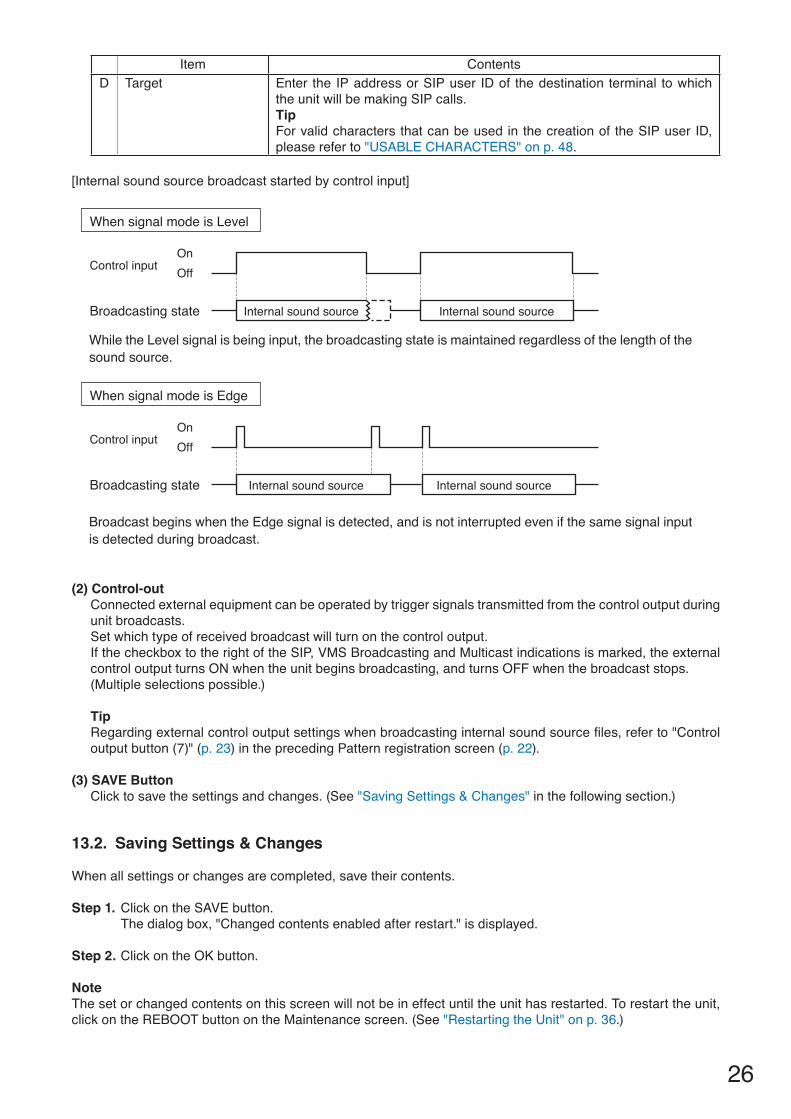
[Internal sound source broadcast started by control input]
Control input
Broadcasting state Internal sound source
OnOff
When signal mode is Level
Control input
Broadcasting state Internal sound source Internal sound source
OnOff
When signal mode is Edge
While the Level signal is being input, the broadcasting state is maintained regardless of the length of the sound source.
Broadcast begins when the Edge signal is detected, and is not interrupted even if the same signal input is detected during broadcast.
Internal sound source
Item ContentsD Target Enter the IP address or SIP user ID of the destination terminal to which
the unit will be making SIP calls.TipFor valid characters that can be used in the creation of the SIP user ID, please refer to "USABLE CHARACTERS" on p. 48.
27
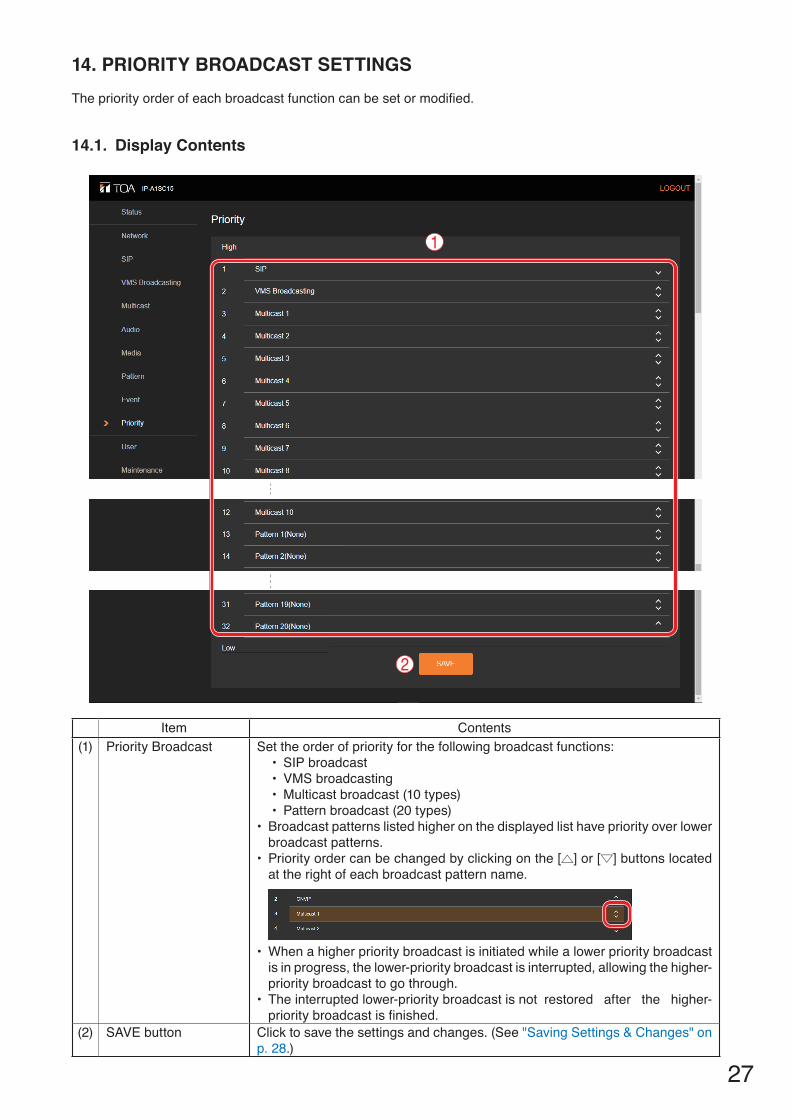
14. PRIORITY BROADCAST SETTINGSThe priority order of each broadcast function can be set or modified.
14.1. Display Contents
Item Contents(1) Priority Broadcast Set the order of priority for the following broadcast functions:
• SIP broadcast• VMS broadcasting• Multicast broadcast (10 types)• Pattern broadcast (20 types)
• Broadcast patterns listed higher on the displayed list have priority over lower broadcast patterns.
• Priority order can be changed by clicking on the [ ] or [ ] buttons located at the right of each broadcast pattern name.
• When a higher priority broadcast is initiated while a lower priority broadcast is in progress, the lower-priority broadcast is interrupted, allowing the higher-priority broadcast to go through.
• The interrupted lower-priority broadcast is not restored after the higher-priority broadcast is finished.
(2) SAVE button Click to save the settings and changes. (See "Saving Settings & Changes" on p. 28.)
1
2

28
14.2. Saving Settings & Changes
When all settings or changes are completed, save their contents.
Step 1. Click on the SAVE button.The dialog box, "Changed contents enabled after restart." is displayed.
Step 2. Click on the OK button.
NoteThe set or changed contents on this screen will not be in effect until the unit has restarted. To restart the unit, click on the REBOOT button on the Maintenance screen. (See "Restarting the Unit" on p. 36.)
[Broadcast switchover performed by broadcast priority settings]
Shown below are examples with the signal mode (p. 25) set to Edge.
Higher priority input
Higher priority input
Control input
Broadcasting state
OnOff
Example of higher priority broadcast being input later
Lower priority inputOnOff
Lower priority input Lower priority input
Higher priority input
Broadcasting state
OnOff
Example of lower priority broadcast being input later
Lower priority inputOnOff
Lower priority input
Input 1*
Broadcasting state
OnOff
Example of same priority broadcast being input later
Input 2*OnOff
When a broadcast of the same priority is in progress, the latter-initiated broadcast is not started.
Lower priority broadcasts initiated while a higher priority broadcast is in progress are not started.
Last input broadcast
* Both are the same priority.
Higher priority input
Control input
Control input
Higher priority input
Lower priority input
First input broadcast
Last input broadcast
Lower priority broadcast is stopped by broadcast of higher priority.
Higher priority input
First input broadcast

29
15. USER SETTINGS SCREENThe username and password required to make a connection to the unit from a PC can be set on this screen.
15.1. Display Contents
Item Contents(1) Username* Enter the current user account name.
Initial setting: admin(2) Password* Enter the current user account password.
Initial setting: guest(3) New Username* Enter the new user account name.(4) New Password* Enter the new user account password.(5) Password
Confirmation*Enter the new user account password once again.
(6) CHANGE button Click to save the settings and changes. (See "Saving Settings & Changes" on p. 30.)
* Perform settings under the following conditions:• For usable characters, please refer to "USABLE CHARACTERS" on p. 48.• Max: 15 characters
12345
6
30
15.2. Saving Settings & Changes
When all settings or changes are completed, save their contents.
Step 1. Click on the CHANGE button.The dialog box is displayed.
Step 2. Click on the OK button.
NoteSettings and changes performed on this screen are enabled immediately after being saved.

31
16. MAINTENANCE SCREENBackup and restoration of unit settings data, initialization, firmware update and hardware restart can all be performed on this screen.
16.1. Display Contents
(1) Back-Up & Restore Settings The unit's setting contents and sound source files can all be saved to the PC or restored to the unit from backup data saved on the PC.The same setting contents can also be duplicated onto other IP-A1SC15 Horn Speakers.
Item ContentsA Config & Media
DownloadAll unit setting contents and sound source files can be saved to the PC as backup data.(See "Downloading Settings Data" on p. 32.)NoteLogin passwords and user names are not included in the backup data.
B Config & Media Upload
All setting contents and sound source files can be restored to the unit from backup data saved on the PC. (See "Uploading Settings Data" on p. 33.)NoteUser and Network settings are not included in the backup data.
C RESET All unit setting contents can be returned to the initial settings as shipped from the factory. However, saved sound source files are not deleted from the unit. (See "Initialization of Settings" on p. 34.)
D FACTORY RESET All unit setting contents can be returned to the default settings as shipped from the factory. All saved sound source files are also deleted.(See "Factory Default Settings" on p. 35.)
1
2
3
A
B
C D
EF
G
32
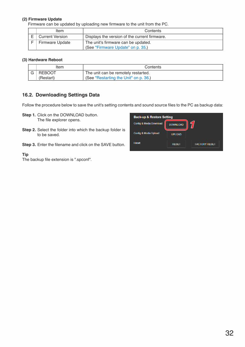
(2) Firmware Update Firmware can be updated by uploading new firmware to the unit from the PC.
Item ContentsE Current Version Displays the version of the current firmware.F Firmware Update The unit's firmware can be updated.
(See "Firmware Update" on p. 35.)
(3) Hardware RebootItem Contents
G REBOOT(Restart)
The unit can be remotely restarted. (See "Restarting the Unit" on p. 36.)
16.2. Downloading Settings Data
Follow the procedure below to save the unit's setting contents and sound source files to the PC as backup data:
Step 1. Click on the DOWNLOAD button. The file explorer opens.
Step 2. Select the folder into which the backup folder is to be saved.
Step 3. Enter the filename and click on the SAVE button.
TipThe backup file extension is ".spconf".
1
33
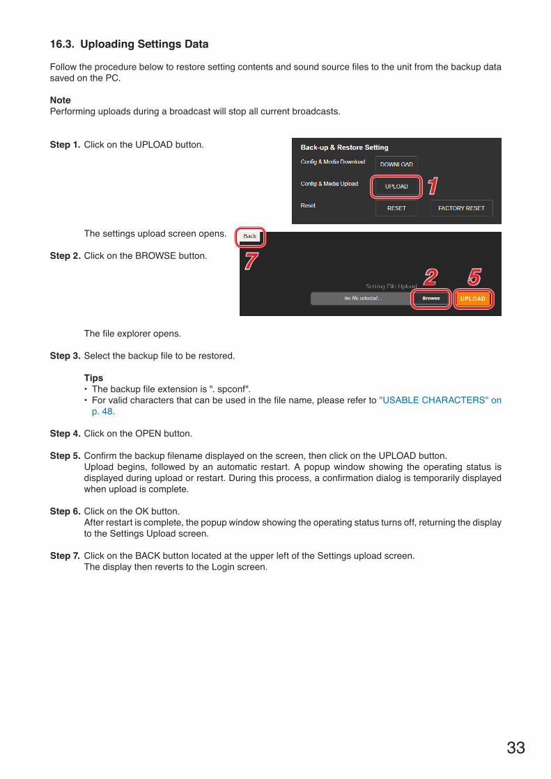
16.3. Uploading Settings Data
Follow the procedure below to restore setting contents and sound source files to the unit from the backup data saved on the PC.
NotePerforming uploads during a broadcast will stop all current broadcasts.
Step 1. Click on the UPLOAD button.
The settings upload screen opens.
Step 2. Click on the BROWSE button.
The file explorer opens.
Step 3. Select the backup file to be restored.
Tips• The backup file extension is ". spconf".• For valid characters that can be used in the file name, please refer to "USABLE CHARACTERS" on
p. 48.
Step 4. Click on the OPEN button.
Step 5. Confirm the backup filename displayed on the screen, then click on the UPLOAD button. Upload begins, followed by an automatic restart. A popup window showing the operating status is displayed during upload or restart. During this process, a confirmation dialog is temporarily displayed when upload is complete.
Step 6. Click on the OK button.After restart is complete, the popup window showing the operating status turns off, returning the display to the Settings Upload screen.
Step 7. Click on the BACK button located at the upper left of the Settings upload screen. The display then reverts to the Login screen.
1
2 57
34
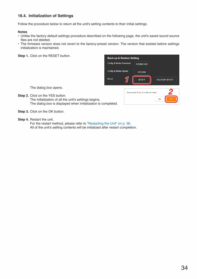
16.4. Initialization of Settings
Follow the procedure below to return all the unit's setting contents to their initial settings.
Notes• Unlike the factory default settings procedure described on the following page, the unit's saved sound source
files are not deleted.• The firmware version does not revert to the factory-preset version. The version that existed before settings
initialization is maintained.
Step 1. Click on the RESET button.
The dialog box opens.
Step 2. Click on the YES button.The initialization of all the unit's settings begins.The dialog box is displayed when initialization is completed.
Step 3. Click on the OK button.
Step 4. Restart the unit.For the restart method, please refer to "Restarting the Unit" on p. 36.All of the unit's setting contents will be initialized after restart completion.
12
35
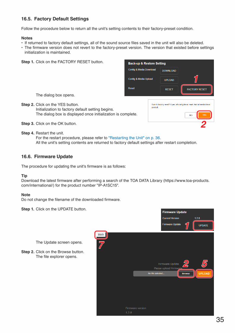
16.5. Factory Default Settings
Follow the procedure below to return all the unit's setting contents to their factory-preset condition.
Notes• If returned to factory default settings, all of the sound source files saved in the unit will also be deleted.• The firmware version does not revert to the factory-preset version. The version that existed before settings
initialization is maintained.
Step 1. Click on the FACTORY RESET button.
The dialog box opens.
Step 2. Click on the YES button.Initialization to factory default setting begins.The dialog box is displayed once initialization is complete.
Step 3. Click on the OK button.
Step 4. Restart the unit.For the restart procedure, please refer to "Restarting the Unit" on p. 36.All the unit's setting contents are returned to factory default settings after restart completion.
16.6. Firmware Update
The procedure for updating the unit's firmware is as follows:
TipDownload the latest firmware after performing a search of the TOA DATA Library (https://www.toa-products.com/international/) for the product number "IP-A1SC15".
NoteDo not change the filename of the downloaded firmware.
Step 1. Click on the UPDATE button.
The Update screen opens.
Step 2. Click on the Browse button.The file explorer opens.
1
2
1
2 5
7

36
Step 3. Select the new firmware file.TipThe firmware filename is displayed in the format "IP-A1SC15_vxxxx.bin," where "xxxx" is the version number.
Step 4. Click on the OPEN button.
Step 5. Confirm the firmware filename displayed on the screen, then click on the UPLOAD button.The dialog box is displayed.
Step 6. Click on the OK button.Upload of the new firmware begins and the unit is restarted.After restart is completed, the unit's status indicator remains continuously lit and the display returns to the Update screen. NoteDo not restart the unit or turn off its power during firmware update, as doing so could result in corrupted firmware, potentially making it impossible to start the unit.
Step 7. Click on the BACK button located at the upper left of the Update screen.The display reverts to the Login screen.
Step 8. After logging in again, confirm that the new firmware version is displayed in the Firmware Version field on the Status screen.
TipAfter firmware update, all settings and sound source files are maintained without being initialized.
16.7. Restarting the Unit
The procedure for restarting (or rebooting) the unit is as follows:
Step 1. Click on the REBOOT button.A confirmation dialog box is displayed.
Step 2. Click on the YES button.The network connection with the unit is disconnected, causing the unit to automatically restart. After restart is completed, the unit's status indicator remains continuously lit.
1
37
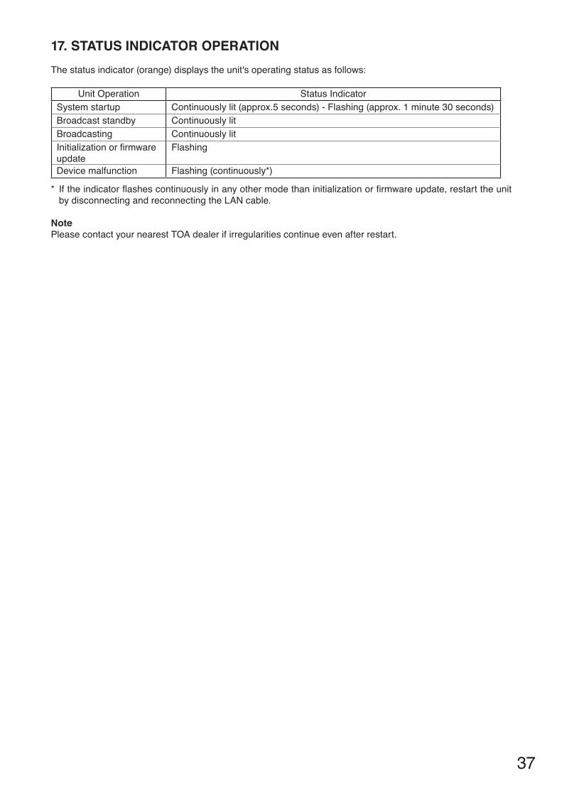
17. STATUS INDICATOR OPERATIONThe status indicator (orange) displays the unit's operating status as follows:
Unit Operation Status IndicatorSystem startup Continuously lit (approx.5 seconds) - Flashing (approx. 1 minute 30 seconds)Broadcast standby Continuously litBroadcasting Continuously litInitialization or firmwareupdate
Flashing
Device malfunction Flashing (continuously*)
* If the indicator flashes continuously in any other mode than initialization or firmware update, restart the unit by disconnecting and reconnecting the LAN cable.
NotePlease contact your nearest TOA dealer if irregularities continue even after restart.
38
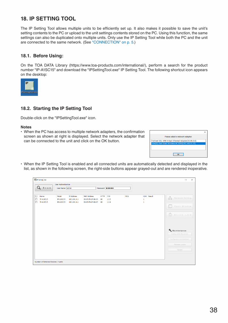
18. IP SETTING TOOLThe IP Setting Tool allows multiple units to be efficiently set up. It also makes it possible to save the unit's setting contents to the PC or upload to the unit settings contents stored on the PC. Using this function, the same settings can also be duplicated onto multiple units. Only use the IP Setting Tool while both the PC and the unit are connected to the same network. (See "CONNECTION" on p. 5.)
18.1. Before Using:
On the TOA DATA Library (https://www.toa-products.com/international/), perform a search for the product number "IP-A1SC15" and download the "IPSettingTool.exe" IP Setting Tool. The following shortcut icon appears on the desktop:
18.2. Starting the IP Setting Tool
Double-click on the "IPSettingTool.exe" icon.
Notes• When the PC has access to multiple network adapters, the confirmation
screen as shown at right is displayed. Select the network adapter that can be connected to the unit and click on the OK button.
• When the IP Setting Tool is enabled and all connected units are automatically detected and displayed in the list, as shown in the following screen, the right-side buttons appear grayed-out and are rendered inoperative.

39
Selecting any unit in the list by marking its corresponding checkbox activates its right-side button, thus making it possible to click on.
18.3. Setting Method
18.3.1. Display Contents
Notes• Perform Steps (4) and (10) after selecting the unit by marking the checkbox in the Detection Results list. • The operation results for Items (4), (6) to (10) are displayed in the Results field of the Detection Results list.• Units currently in Restart mode are not displayed.
1 2
3 45
6
78910
(1) Scan buttonClick on this button to detect all units connected to the network. All connected units are individually detected each time the button is clicked.
(2) Username and PasswordEnter the username and password of the unit to be operated. When the IP Setting Tool starts up, the unit's default values (Username: admin; Password: guest) are entered.

40
(3) Detection Results listDisplays a list of detected units.
(4) Network Setting buttonClicking on this button displays the Network Settings screen of the selected IP-A1SC15. (See "Network Settings" on p. 41.)
(5) Open Window buttonClicking on this button causes the browser to start up, displaying the Login screen for the selected IP-A1SC15. (See "CONNECTION" on p. 5.)
(6) Blink LED buttonWhen clicked, the status indicator for the selected unit flashes 3 times.
(7) Configuration file upload buttonClick on this button to upload the settings file to the unit from the PC. The same settings file can also be simultaneously uploaded to multiple units. For details, please refer to "Uploading Settings Files" on p. 44.
(8) Configuration file download buttonClick on this button to download the settings file to the PC from the unit. The downloaded settings file can be used as the original file when uploading the same settings file to multiple units. For details, please refer to "Downloading Settings Files" on p. 45.
(9) Firmware Update buttonClick on this button to update the unit's firmware. The same firmware update can also be simultaneously carried out on multiple units. For details, please refer to "Firmware Update" on p. 46.
(10) Restart button Click on this button to restart the unit(s).

41
18.4. User Authentication
Step 1. Enter the username and password.
Enter the username and password set for the detected unit.When setting up an unconfigured or initialized unit, enter the following username and password:
Username: adminPassword: guest
TipTo change the setting contents of the unit(s) detected by the IP Setting Tool, the user authentication requirements of each unit must be met.
Step 2. Click on the Scan button. All detected units are displayed on the Detection Results list, enabling the operation of buttons (4) to (10).
18.5. Network Settings
Perform all network settings, including the IP address, etc.
1 25
Step 1. Select the unit(s) for which network settings will be performed by marking the corresponding checkbox in the Detection Results list.
Step 2. Click on the Network Setting button.When only one unit is selected, the Network settings screen for Single Setting is displayed. When multiple units are selected, the following confirmation dialog box is displayed. Clicking on the OK button displays the Network settings screen for Multiple Setting.
12
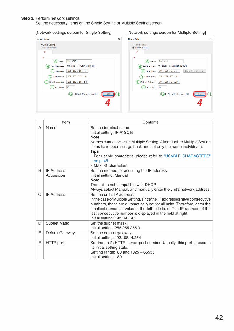
42
Step 3. Perform network settings.Set the necessary items on the Single Setting or Multiple Setting screen.
[Network settings screen for Single Setting] [Network settings screen for Multiple Setting]
Item ContentsA Name Set the terminal name.
Initial setting: IP-A1SC15NoteNames cannot be set in Multiple Setting. After all other Multiple Setting items have been set, go back and set only the name individually. Tips• For usable characters, please refer to "USABLE CHARACTERS"
on p. 48.• Max: 31 characters
B IP AddressAcquisition
Set the method for acquiring the IP address. Initial setting: ManualNoteThe unit is not compatible with DHCP.Always select Manual, and manually enter the unit's network address.
C IP Address Set the unit's IP address.In the case of Multiple Setting, since the IP addresses have consecutive numbers, these are automatically set for all units. Therefore, enter the smallest numerical value in the left-side field. The IP address of the last consecutive number is displayed in the field at right.Initial setting: 192.168.14.1
D Subnet Mask Set the subnet mask.Initial setting: 255.255.255.0
E Default Gateway Set the default gateway.Initial setting: 192.168.14.254
F HTTP port Set the unit's HTTP server port number. Usually, this port is used in its initial setting state.Setting range: 80 and 1025 – 65535 Initial setting: 80
AB
CD
EF
G H
4
AB
CD
EF
G H
4

43
Item ContentsG Confirm IP address
conflictMark the checkbox to confirm whether there are any conflicting IP addresses.Tips• Even if the checkbox for the item "Confirm IP address conflict" is
marked, certain conflicts related to network IP addresses that are different from the network adapter in use cannot be confirmed.
• When an IP address conflict is detected, the indication "IP address conflict" appears in the display screen's Results field.
H Set Click on this button to finalize the set contents.
Step 4. Click on the Set button.This completes the network settings.The Network settings screen closes and the unit automatically restarts.
Step 5. Click on the Scan button.The display screen is updated.

44
18.6. Uploading Settings Files
1
1
4
NotePerforming uploads during a broadcast will stop all current broadcasts.
Step 1. Select the units and click on the Configuration file upload button.The file selection screen is displayed.
Step 2. Click on the Select button and select the settings file (extension ".spconf") to be uploaded to the units.
Step 3. Click on the Run button.Settings file upload begins. After upload is complete, the indication "OK" is displayed in the Results field, followed by automatic restart.
Step 4. Click on the Scan button.The display screen is updated. Notes• Do not restart the unit or turn off power during settings file upload.• If the unit is restarted or power is turned off during upload, the settings file could become corrupted,
potentially making it impossible to start the unit.• Under circumstances in which the load on the unit or network is high, the indication "No response"
may be displayed in the Results field of the Detection Results list. In such cases, simply wait for a while. However, if the Result field is not updated, click on the Scan button again.
• When uploading the settings file, the sound source files are also copied to the unit. The user and network settings are not applied to the unit even if the settings file is uploaded, and their pre-upload settings are maintained.
2 3

45
18.7. Downloading Settings Files
1
1
4
Step 1. Select the units and click on the Configuration file download button.The screen for selecting the download destination folder is displayed.
Step 2. Click on the Select button to select the download destination folder.
Step 3. Click on the Run button.Settings file download begins. After the download is completed, the OK indication appears in the Detection results list's Results field.The filename extension of the saved settings file is ".spconf."Notes• Do not restart the unit or turn off power during settings file download. If the unit is restarted or power is turned off during download, the settings file could become corrupted,
potentially making it impossible to save the file.• Downloading the settings file causes the setting data, including sound source files, to be downloaded.
New network and user settings are not applied when the settings are restored or replicated by means of download and upload.
2 3
46
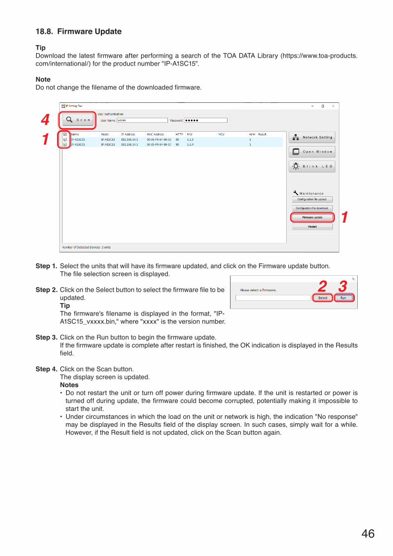
18.8. Firmware Update
TipDownload the latest firmware after performing a search of the TOA DATA Library (https://www.toa-products.com/international/) for the product number "IP-A1SC15".
NoteDo not change the filename of the downloaded firmware.
1
1
4
Step 1. Select the units that will have its firmware updated, and click on the Firmware update button.The file selection screen is displayed.
Step 2. Click on the Select button to select the firmware file to be updated.TipThe firmware's filename is displayed in the format, "IP-A1SC15_vxxxx.bin," where "xxxx" is the version number.
Step 3. Click on the Run button to begin the firmware update.If the firmware update is complete after restart is finished, the OK indication is displayed in the Results field.
Step 4. Click on the Scan button.The display screen is updated.Notes• Do not restart the unit or turn off power during firmware update. If the unit is restarted or power is
turned off during update, the firmware could become corrupted, potentially making it impossible to start the unit.
• Under circumstances in which the load on the unit or network is high, the indication "No response" may be displayed in the Results field of the display screen. In such cases, simply wait for a while. However, if the Result field is not updated, click on the Scan button again.
2 3
47
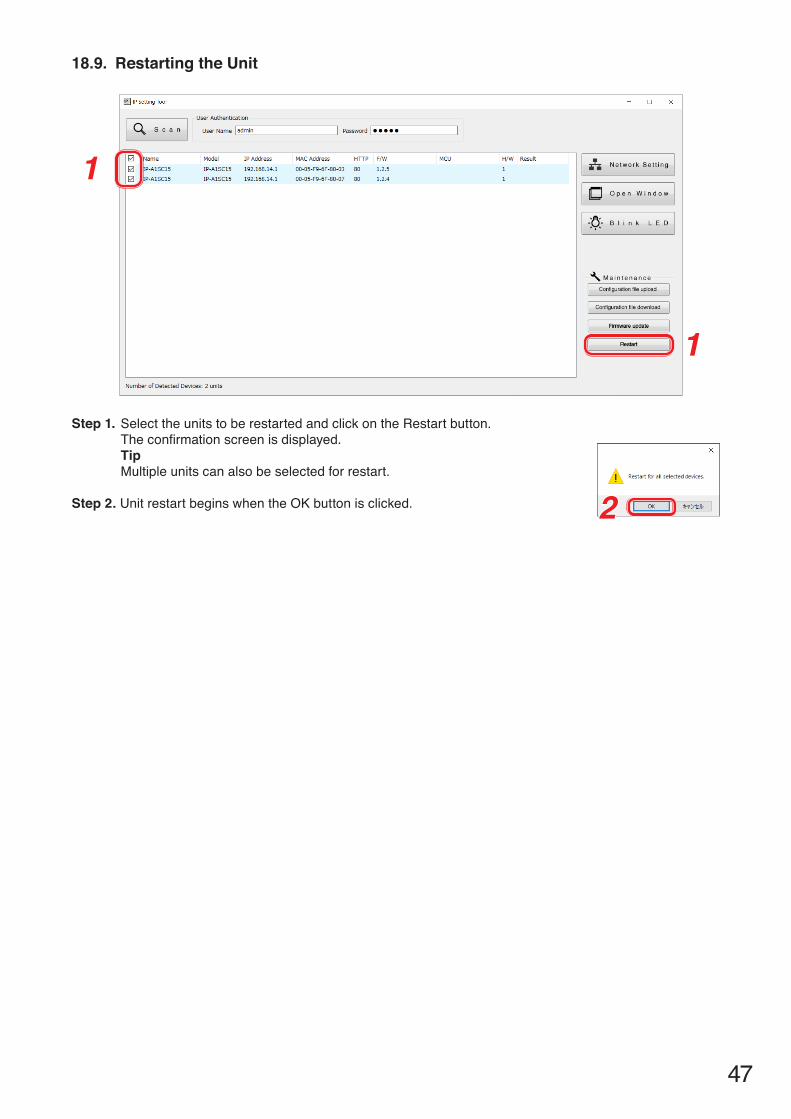
18.9. Restarting the Unit
1
1
Step 1. Select the units to be restarted and click on the Restart button.The confirmation screen is displayed.TipMultiple units can also be selected for restart.
Step 2. Unit restart begins when the OK button is clicked. 2

48
19. USABLE CHARACTERS19.1. Characters That Can Be Used for Names, Authentication ID and Passwords
TargetAlphabeticalUpper case letters A – Z
AlphabeticalLower case letters a – z
Numerical0 – 9
Symbols [“-” (hyphen)] and [“_” (underscore)]
Other symbols*
Login screen Username × ×Password × ×
Network settings screen Terminal Name ×SIP settings screen User ID ×
Display Name ×PasswordAuthentication ID ×
VMS Broadcasting settings screen
Username × ×Password × ×
Pattern registratration screen
Pattern Name ×
Event settings screen SIP 1 TargetUser ID ×
SIP 2 TargetUser ID ×
* These following 14 symbols: ! # % + , . = @ [ ] ^ { } ~
TipCharacters that can be used when entering the "Name (Terminal Name)" with the IP settings tool are the same as those used for the [Terminal Name] on the Network Settings Screen shown above.
19.2. Characters That Can Be Used for Filenames
TargetAlphabeticalUpper case letters A – Z
AlphabeticalLower case letters a – z
Numerical0 – 9
Symbols [“-” (hyphen)] and [“_” (underscore)]
Other symbols*
Media setting screen Media file name(*.wav, *.mp3)
Maintenance screen Config file name(*.spconf)
* These following 14 symbols: ! # % + , . = @ [ ] ^ { } ~
TipCharacters that can be used for filenames when performing "Setting Upload" by means of the IP settings tool are the same as those used for the "Config filename" on the Maintenance Screen shown above.

URL: https://www.toa.jp/202007
Traceability Information for EuropeManufacturer:
TOA Corporation7-2-1, Minatojima-Nakamachi, Chuo-ku, Kobe, Hyogo, Japan
Authorized representative:TOA Electronics Europe GmbHSuederstrasse 282, 20537 Hamburg,Germany
Traceability Information for USAManufacturer:
TOA Corporation7-2-1, Minatojima-Nakamachi, Chuo-ku, Kobe, Hyogo, Japan
Authorized representative:TOA Electronics, Inc.400 Oyster Point Boulevard, Suite 301,South San Francisco, California 94080,USA