ip addressing: ipv4 addressing configuration guide, cisco ... · • ip address classes, page 4 •...
TRANSCRIPT
IP Addressing: IPv4 AddressingConfiguration Guide, Cisco IOS Release12.4
Americas HeadquartersCisco Systems, Inc.170 West Tasman DriveSan Jose, CA 95134-1706USAhttp://www.cisco.comTel: 408 526-4000 800 553-NETS (6387)Fax: 408 527-0883

THE SPECIFICATIONS AND INFORMATION REGARDING THE PRODUCTS IN THIS MANUAL ARE SUBJECT TO CHANGE WITHOUT NOTICE. ALL STATEMENTS,INFORMATION, AND RECOMMENDATIONS IN THIS MANUAL ARE BELIEVED TO BE ACCURATE BUT ARE PRESENTED WITHOUT WARRANTY OF ANY KIND,EXPRESS OR IMPLIED. USERS MUST TAKE FULL RESPONSIBILITY FOR THEIR APPLICATION OF ANY PRODUCTS.
THE SOFTWARE LICENSE AND LIMITED WARRANTY FOR THE ACCOMPANYING PRODUCT ARE SET FORTH IN THE INFORMATION PACKET THAT SHIPPEDWITH THE PRODUCT AND ARE INCORPORATED HEREIN BY THIS REFERENCE. IF YOU ARE UNABLE TO LOCATE THE SOFTWARE LICENSE OR LIMITEDWARRANTY, CONTACT YOUR CISCO REPRESENTATIVE FOR A COPY.
The Cisco implementation of TCP header compression is an adaptation of a program developed by the University of California, Berkeley (UCB) as part of UCB’s public domain versionof the UNIX operating system. All rights reserved. Copyright © 1981, Regents of the University of California.
NOTWITHSTANDING ANY OTHER WARRANTY HEREIN, ALL DOCUMENT FILES AND SOFTWARE OF THESE SUPPLIERS ARE PROVIDED “AS IS” WITH ALLFAULTS. CISCO AND THE ABOVE-NAMED SUPPLIERS DISCLAIM ALL WARRANTIES, EXPRESSED OR IMPLIED, INCLUDING, WITHOUT LIMITATION, THOSE OFMERCHANTABILITY, FITNESS FOR A PARTICULAR PURPOSE AND NONINFRINGEMENT OR ARISING FROM A COURSE OF DEALING, USAGE, OR TRADEPRACTICE.
IN NO EVENT SHALL CISCO OR ITS SUPPLIERS BE LIABLE FOR ANY INDIRECT, SPECIAL, CONSEQUENTIAL, OR INCIDENTAL DAMAGES, INCLUDING,WITHOUT LIMITATION, LOST PROFITS OR LOSS OR DAMAGE TO DATA ARISING OUT OF THE USE OR INABILITY TO USE THIS MANUAL, EVEN IF CISCO ORITS SUPPLIERS HAVE BEEN ADVISED OF THE POSSIBILITY OF SUCH DAMAGES.
Cisco and the Cisco logo are trademarks or registered trademarks of Cisco and/or its affiliates in the U.S. and other countries. To view a list of Cisco trademarks, go to this URL: www.cisco.com/go/trademarks. Third-party trademarks mentioned are the property of their respective owners. The use of the word partner does not imply a partnership relationshipbetween Cisco and any other company. (1110R)
Any Internet Protocol (IP) addresses and phone numbers used in this document are not intended to be actual addresses and phone numbers. Any examples, command display output,network topology diagrams, and other figures included in the document are shown for illustrative purposes only. Any use of actual IP addresses or phone numbers in illustrative contentis unintentional and coincidental.
© 2011 Cisco Systems, Inc. All rights reserved.
C O N T E N T S
Configuring IPv4 Addresses 1
Finding Feature Information 1
Information About IP Addresses 1
Binary Numbering 2
IP Address Structure 3
IP Address Classes 4
IP Network Subnetting 6
IP Network Address Assignments 8
Classless Inter-Domain Routing 10
Prefixes 10
How to Configure IP Addresses 11
Establishing IP Connectivity to a Network by Assigning an IP Address to an Interface 11
Troubleshooting Tips 12
Increasing the Number of IP Hosts that Are Supported on a Network by Using Secondary IP
Addresses 12
Troubleshooting Tips 14
What to Do Next 14
Maximizing the Number of Available IP Subnets by Allowing the Use of IP Subnet Zero 14
Troubleshooting Tips 16
Specifying the Format of Network Masks 16
Specifying the Format in Which Netmasks Appear for the Current Session 16
Specifying the Format in Which Netmasks Appear for an Individual Line 17
Using IP Unnumbered Interfaces on Point-to-Point WAN Interfaces to Limit Number of IP
Addresses Required 18
IP Unnumbered Feature 18
Troubleshooting Tips 20
Using IP addresses with 31-Bit Prefixes on Point-to-Point WAN Interfaces to Limit Number of
IP Addresses Required 20
RFC 3021 20
IP Addressing: IPv4 Addressing Configuration Guide, Cisco IOS Release 12.4 iii
Troubleshooting Tips 23
Configuration Examples for IP Addresses 23
Example Establishing IP Connectivity to a Network by Assigning an IP Address to an
Interface 24
Example Increasing the Number of IP Hosts that are Supported on a Network by Using
Secondary IP Addresses 24
Example Using IP Unnumbered Interfaces on Point-to-Point WAN Interfaces to Limit
Number of IP Addresses Required 24
Example Using IP addresses with 31-Bit Prefixes on Point-to-Point WAN Interfaces to
Limit Number of IP Addresses Required 25
Example Maximizing the Number of Available IP Subnets by Allowing the Use of IP
Subnet Zero 25
Where to Go Next 25
Additional References 25
Feature Information for IP Addresses 27
Contents
IP Addressing: IPv4 Addressing Configuration Guide, Cisco IOS Release 12.4iv
Configuring IPv4 Addresses
This chapter contains information about, and instructions for configuring IPv4 addresses on interfaces thatare part of a networking device.
Note All further references to IPv4 addresses in this document use only IP in the text, not IPv4.
• Finding Feature Information, page 1• Information About IP Addresses, page 1• How to Configure IP Addresses, page 11• Configuration Examples for IP Addresses, page 23• Where to Go Next, page 25• Additional References, page 25• Feature Information for IP Addresses, page 27
Finding Feature InformationYour software release may not support all the features documented in this module. For the latest featureinformation and caveats, see the release notes for your platform and software release. To find informationabout the features documented in this module, and to see a list of the releases in which each feature issupported, see the Feature Information Table at the end of this document.
Use Cisco Feature Navigator to find information about platform support and Cisco software image support.To access Cisco Feature Navigator, go to www.cisco.com/go/cfn. An account on Cisco.com is not required.
Information About IP Addresses• Binary Numbering, page 2
• IP Address Structure, page 3
• IP Address Classes, page 4
• IP Network Subnetting, page 6
• IP Network Address Assignments, page 8
• Classless Inter-Domain Routing, page 10
• Prefixes, page 10
IP Addressing: IPv4 Addressing Configuration Guide, Cisco IOS Release 12.4 1
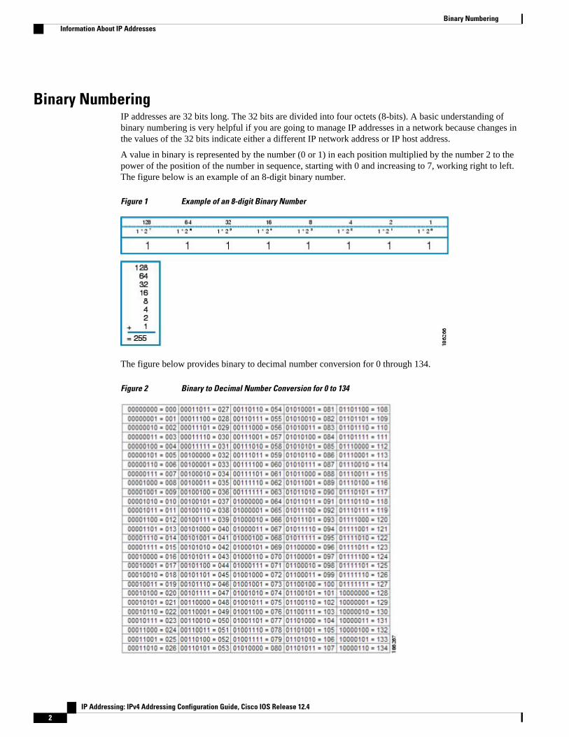
Binary NumberingIP addresses are 32 bits long. The 32 bits are divided into four octets (8-bits). A basic understanding ofbinary numbering is very helpful if you are going to manage IP addresses in a network because changes inthe values of the 32 bits indicate either a different IP network address or IP host address.
A value in binary is represented by the number (0 or 1) in each position multiplied by the number 2 to thepower of the position of the number in sequence, starting with 0 and increasing to 7, working right to left.The figure below is an example of an 8-digit binary number.
Figure 1 Example of an 8-digit Binary Number
The figure below provides binary to decimal number conversion for 0 through 134.
Figure 2 Binary to Decimal Number Conversion for 0 to 134
Binary Numbering Information About IP Addresses
IP Addressing: IPv4 Addressing Configuration Guide, Cisco IOS Release 12.42
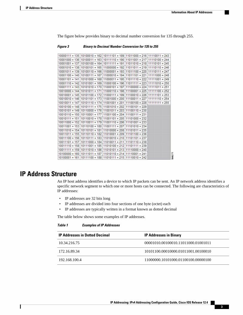
The figure below provides binary to decimal number conversion for 135 through 255.
Figure 3 Binary to Decimal Number Conversion for 135 to 255
IP Address StructureAn IP host address identifies a device to which IP packets can be sent. An IP network address identifies aspecific network segment to which one or more hosts can be connected. The following are characteristics ofIP addresses:
• IP addresses are 32 bits long• IP addresses are divided into four sections of one byte (octet) each• IP addresses are typically written in a format known as dotted decimal
The table below shows some examples of IP addresses.
Table 1 Examples of IP Addresses
IP Addresses in Dotted Decimal IP Addresses in Binary
10.34.216.75 00001010.00100010.11011000.01001011
172.16.89.34 10101100.00010000.01011001.00100010
192.168.100.4 11000000.10101000.01100100.00000100
IP Address StructureInformation About IP Addresses
IP Addressing: IPv4 Addressing Configuration Guide, Cisco IOS Release 12.4 3
Note The IP addresses in the table above are from RFC 1918, Address Allocation for Private Internets . These IPaddresses are not routable on the Internet. They are intended for use in private networks. For moreinformation on RFC1918, see http://www.ietf.org/rfc/rfc1918.txt .
IP addresses are further subdivided into two sections known as network and host. The division isaccomplished by arbitrarily ranges of IP addresses to classes. For more information see RFC 791 InternetProtocol at http://www.ietf.org/rfc/rfc0791.txt .
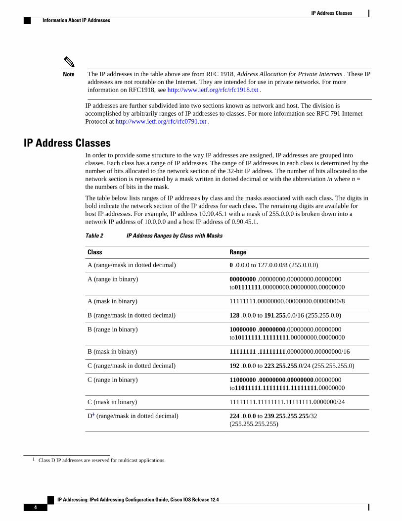
IP Address ClassesIn order to provide some structure to the way IP addresses are assigned, IP addresses are grouped intoclasses. Each class has a range of IP addresses. The range of IP addresses in each class is determined by thenumber of bits allocated to the network section of the 32-bit IP address. The number of bits allocated to thenetwork section is represented by a mask written in dotted decimal or with the abbreviation /n where n =the numbers of bits in the mask.
The table below lists ranges of IP addresses by class and the masks associated with each class. The digits inbold indicate the network section of the IP address for each class. The remaining digits are available forhost IP addresses. For example, IP address 10.90.45.1 with a mask of 255.0.0.0 is broken down into anetwork IP address of 10.0.0.0 and a host IP address of 0.90.45.1.
Table 2 IP Address Ranges by Class with Masks
Class Range
A (range/mask in dotted decimal) 0 .0.0.0 to 127.0.0.0/8 (255.0.0.0)
A (range in binary) 00000000 .00000000.00000000.00000000to01111111.00000000.00000000.00000000
A (mask in binary) 11111111.00000000.00000000.00000000/8
B (range/mask in dotted decimal) 128 .0.0.0 to 191.255.0.0/16 (255.255.0.0)
B (range in binary) 10000000 .00000000.00000000.00000000to10111111.11111111.00000000.00000000
B (mask in binary) 11111111 .11111111.00000000.00000000/16
C (range/mask in dotted decimal) 192 .0.0.0 to 223.255.255.0/24 (255.255.255.0)
C (range in binary) 11000000 .00000000.00000000.00000000to11011111.11111111.11111111.00000000
C (mask in binary) 11111111.11111111.11111111.0000000/24
D1 (range/mask in dotted decimal) 224 .0.0.0 to 239.255.255.255/32(255.255.255.255)
1 Class D IP addresses are reserved for multicast applications.
IP Address Classes Information About IP Addresses
IP Addressing: IPv4 Addressing Configuration Guide, Cisco IOS Release 12.44
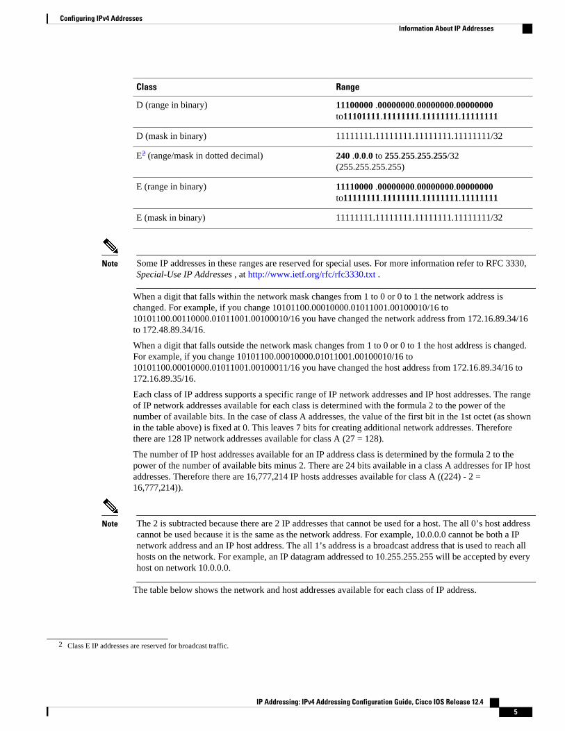
Class Range
D (range in binary) 11100000 .00000000.00000000.00000000to11101111.11111111.11111111.11111111
D (mask in binary) 11111111.11111111.11111111.11111111/32
E2 (range/mask in dotted decimal) 240 .0.0.0 to 255.255.255.255/32(255.255.255.255)
E (range in binary) 11110000 .00000000.00000000.00000000to11111111.11111111.11111111.11111111
E (mask in binary) 11111111.11111111.11111111.11111111/32
Note Some IP addresses in these ranges are reserved for special uses. For more information refer to RFC 3330,Special-Use IP Addresses , at http://www.ietf.org/rfc/rfc3330.txt .
When a digit that falls within the network mask changes from 1 to 0 or 0 to 1 the network address ischanged. For example, if you change 10101100.00010000.01011001.00100010/16 to10101100.00110000.01011001.00100010/16 you have changed the network address from 172.16.89.34/16to 172.48.89.34/16.
When a digit that falls outside the network mask changes from 1 to 0 or 0 to 1 the host address is changed.For example, if you change 10101100.00010000.01011001.00100010/16 to10101100.00010000.01011001.00100011/16 you have changed the host address from 172.16.89.34/16 to172.16.89.35/16.
Each class of IP address supports a specific range of IP network addresses and IP host addresses. The rangeof IP network addresses available for each class is determined with the formula 2 to the power of thenumber of available bits. In the case of class A addresses, the value of the first bit in the 1st octet (as shownin the table above) is fixed at 0. This leaves 7 bits for creating additional network addresses. Thereforethere are 128 IP network addresses available for class A (27 = 128).
The number of IP host addresses available for an IP address class is determined by the formula 2 to thepower of the number of available bits minus 2. There are 24 bits available in a class A addresses for IP hostaddresses. Therefore there are 16,777,214 IP hosts addresses available for class A ((224) - 2 =16,777,214)).
Note The 2 is subtracted because there are 2 IP addresses that cannot be used for a host. The all 0’s host addresscannot be used because it is the same as the network address. For example, 10.0.0.0 cannot be both a IPnetwork address and an IP host address. The all 1’s address is a broadcast address that is used to reach allhosts on the network. For example, an IP datagram addressed to 10.255.255.255 will be accepted by everyhost on network 10.0.0.0.
The table below shows the network and host addresses available for each class of IP address.
2 Class E IP addresses are reserved for broadcast traffic.
Configuring IPv4 AddressesInformation About IP Addresses
IP Addressing: IPv4 Addressing Configuration Guide, Cisco IOS Release 12.4 5
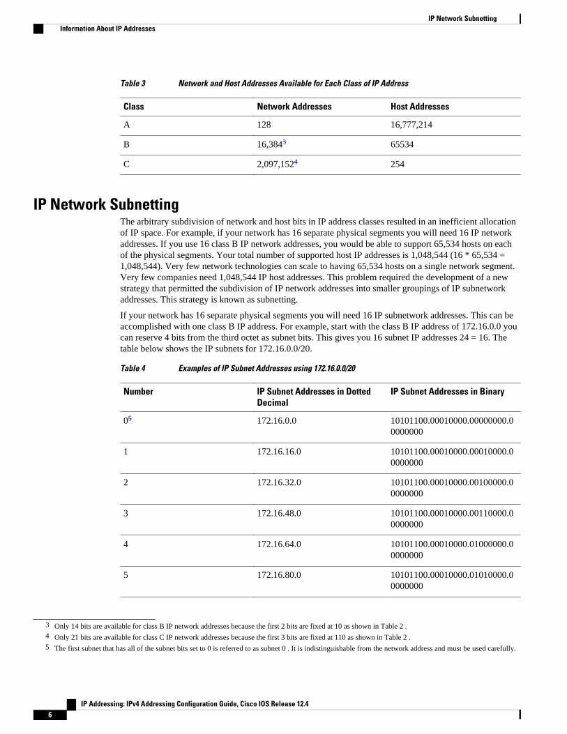
Table 3 Network and Host Addresses Available for Each Class of IP Address
Class Network Addresses Host Addresses
A 128 16,777,214
B 16,3843 65534
C 2,097,1524 254
IP Network SubnettingThe arbitrary subdivision of network and host bits in IP address classes resulted in an inefficient allocationof IP space. For example, if your network has 16 separate physical segments you will need 16 IP networkaddresses. If you use 16 class B IP network addresses, you would be able to support 65,534 hosts on eachof the physical segments. Your total number of supported host IP addresses is 1,048,544 (16 * 65,534 =1,048,544). Very few network technologies can scale to having 65,534 hosts on a single network segment.Very few companies need 1,048,544 IP host addresses. This problem required the development of a newstrategy that permitted the subdivision of IP network addresses into smaller groupings of IP subnetworkaddresses. This strategy is known as subnetting.
If your network has 16 separate physical segments you will need 16 IP subnetwork addresses. This can beaccomplished with one class B IP address. For example, start with the class B IP address of 172.16.0.0 youcan reserve 4 bits from the third octet as subnet bits. This gives you 16 subnet IP addresses 24 = 16. Thetable below shows the IP subnets for 172.16.0.0/20.
Table 4 Examples of IP Subnet Addresses using 172.16.0.0/20
Number IP Subnet Addresses in DottedDecimal
IP Subnet Addresses in Binary
05 172.16.0.0 10101100.00010000.00000000.00000000
1 172.16.16.0 10101100.00010000.00010000.00000000
2 172.16.32.0 10101100.00010000.00100000.00000000
3 172.16.48.0 10101100.00010000.00110000.00000000
4 172.16.64.0 10101100.00010000.01000000.00000000
5 172.16.80.0 10101100.00010000.01010000.00000000
3 Only 14 bits are available for class B IP network addresses because the first 2 bits are fixed at 10 as shown in Table 2 .4 Only 21 bits are available for class C IP network addresses because the first 3 bits are fixed at 110 as shown in Table 2 .5 The first subnet that has all of the subnet bits set to 0 is referred to as subnet 0 . It is indistinguishable from the network address and must be used carefully.
IP Network Subnetting Information About IP Addresses
IP Addressing: IPv4 Addressing Configuration Guide, Cisco IOS Release 12.46
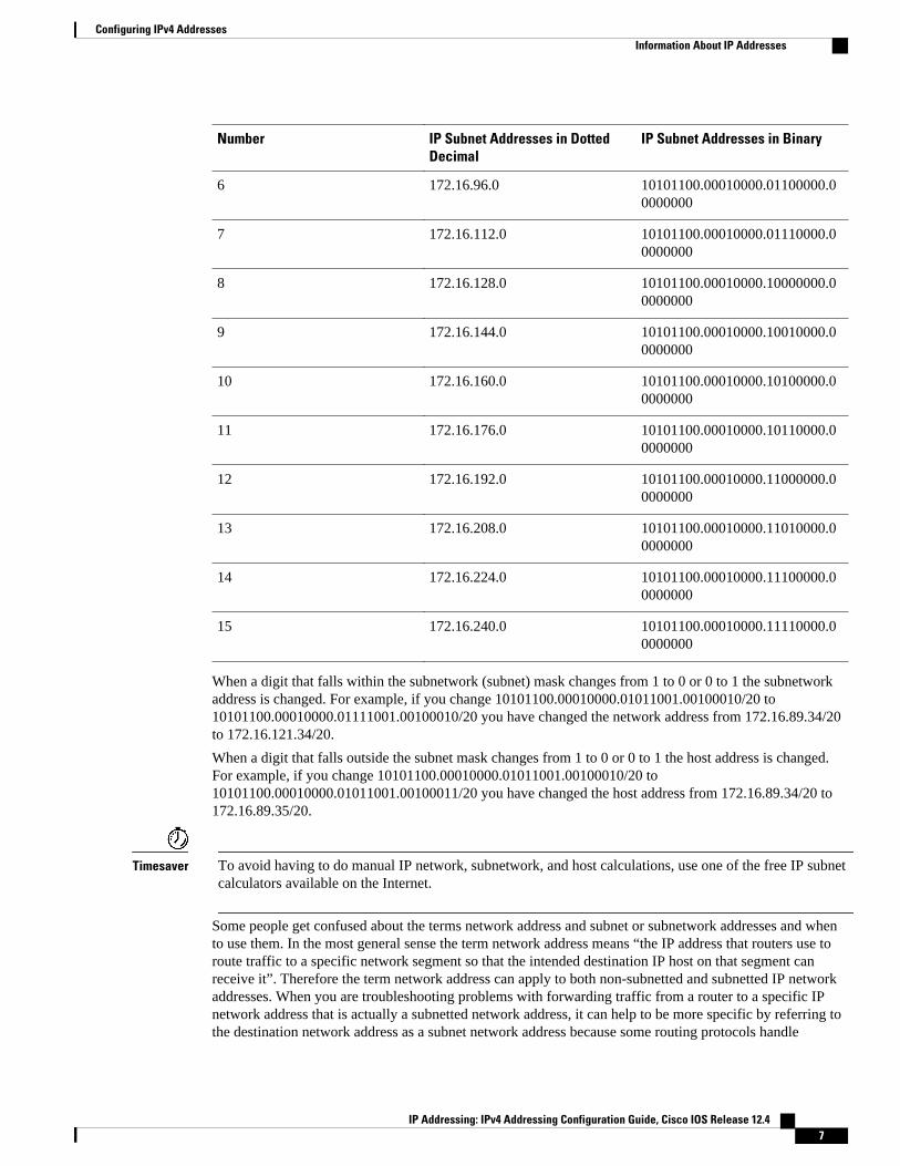
Number IP Subnet Addresses in DottedDecimal
IP Subnet Addresses in Binary
6 172.16.96.0 10101100.00010000.01100000.00000000
7 172.16.112.0 10101100.00010000.01110000.00000000
8 172.16.128.0 10101100.00010000.10000000.00000000
9 172.16.144.0 10101100.00010000.10010000.00000000
10 172.16.160.0 10101100.00010000.10100000.00000000
11 172.16.176.0 10101100.00010000.10110000.00000000
12 172.16.192.0 10101100.00010000.11000000.00000000
13 172.16.208.0 10101100.00010000.11010000.00000000
14 172.16.224.0 10101100.00010000.11100000.00000000
15 172.16.240.0 10101100.00010000.11110000.00000000
When a digit that falls within the subnetwork (subnet) mask changes from 1 to 0 or 0 to 1 the subnetworkaddress is changed. For example, if you change 10101100.00010000.01011001.00100010/20 to10101100.00010000.01111001.00100010/20 you have changed the network address from 172.16.89.34/20to 172.16.121.34/20.
When a digit that falls outside the subnet mask changes from 1 to 0 or 0 to 1 the host address is changed.For example, if you change 10101100.00010000.01011001.00100010/20 to10101100.00010000.01011001.00100011/20 you have changed the host address from 172.16.89.34/20 to172.16.89.35/20.
Timesaver To avoid having to do manual IP network, subnetwork, and host calculations, use one of the free IP subnetcalculators available on the Internet.
Some people get confused about the terms network address and subnet or subnetwork addresses and whento use them. In the most general sense the term network address means “the IP address that routers use toroute traffic to a specific network segment so that the intended destination IP host on that segment canreceive it”. Therefore the term network address can apply to both non-subnetted and subnetted IP networkaddresses. When you are troubleshooting problems with forwarding traffic from a router to a specific IPnetwork address that is actually a subnetted network address, it can help to be more specific by referring tothe destination network address as a subnet network address because some routing protocols handle
Configuring IPv4 AddressesInformation About IP Addresses
IP Addressing: IPv4 Addressing Configuration Guide, Cisco IOS Release 12.4 7
advertising subnet network routes differently from network routes. For example, the default behavior forRIP v2 is to automatically summarize the subnet network addresses that it is connected to their non-subnetted network addresses (172.16.32.0/24 is advertised by RIP v2 as 172.16.0.0/16) when sendingrouting updates to other routers. Therefore the other routers might have knowledge of the IP networkaddresses in the network, but not the subnetted network addresses of the IP network addresses.
Tip The term IP address space is sometimes used to refer to a range of IP addresses. For example, “We have toallocate a new IP network address to our network because we have used all of the available IP addresses inthe current IP address space”.
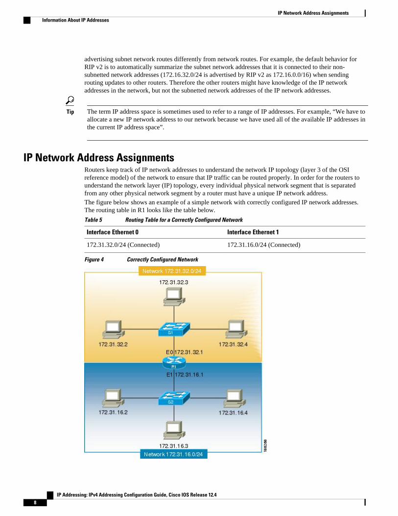
IP Network Address AssignmentsRouters keep track of IP network addresses to understand the network IP topology (layer 3 of the OSIreference model) of the network to ensure that IP traffic can be routed properly. In order for the routers tounderstand the network layer (IP) topology, every individual physical network segment that is separatedfrom any other physical network segment by a router must have a unique IP network address.The figure below shows an example of a simple network with correctly configured IP network addresses.The routing table in R1 looks like the table below.
Table 5 Routing Table for a Correctly Configured Network
Interface Ethernet 0 Interface Ethernet 1
172.31.32.0/24 (Connected) 172.31.16.0/24 (Connected)
Figure 4 Correctly Configured Network
IP Network Address Assignments Information About IP Addresses
IP Addressing: IPv4 Addressing Configuration Guide, Cisco IOS Release 12.48
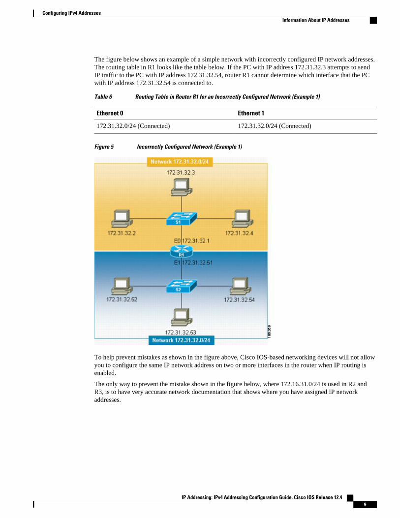
The figure below shows an example of a simple network with incorrectly configured IP network addresses.The routing table in R1 looks like the table below. If the PC with IP address 172.31.32.3 attempts to sendIP traffic to the PC with IP address 172.31.32.54, router R1 cannot determine which interface that the PCwith IP address 172.31.32.54 is connected to.
Table 6 Routing Table in Router R1 for an Incorrectly Configured Network (Example 1)
Ethernet 0 Ethernet 1
172.31.32.0/24 (Connected) 172.31.32.0/24 (Connected)
Figure 5 Incorrectly Configured Network (Example 1)
To help prevent mistakes as shown in the figure above, Cisco IOS-based networking devices will not allowyou to configure the same IP network address on two or more interfaces in the router when IP routing isenabled.
The only way to prevent the mistake shown in the figure below, where 172.16.31.0/24 is used in R2 andR3, is to have very accurate network documentation that shows where you have assigned IP networkaddresses.
Configuring IPv4 AddressesInformation About IP Addresses
IP Addressing: IPv4 Addressing Configuration Guide, Cisco IOS Release 12.4 9
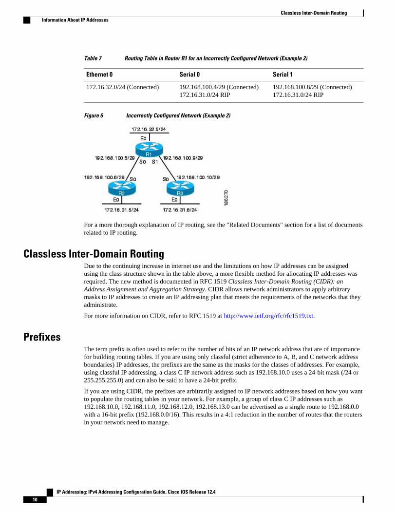
Table 7 Routing Table in Router R1 for an Incorrectly Configured Network (Example 2)
Ethernet 0 Serial 0 Serial 1
172.16.32.0/24 (Connected) 192.168.100.4/29 (Connected)172.16.31.0/24 RIP
192.168.100.8/29 (Connected)172.16.31.0/24 RIP
Figure 6 Incorrectly Configured Network (Example 2)
For a more thorough explanation of IP routing, see the "Related Documents" section for a list of documentsrelated to IP routing.
Classless Inter-Domain RoutingDue to the continuing increase in internet use and the limitations on how IP addresses can be assignedusing the class structure shown in the table above, a more flexible method for allocating IP addresses wasrequired. The new method is documented in RFC 1519 Classless Inter-Domain Routing (CIDR): anAddress Assignment and Aggregation Strategy. CIDR allows network administrators to apply arbitrarymasks to IP addresses to create an IP addressing plan that meets the requirements of the networks that theyadministrate.
For more information on CIDR, refer to RFC 1519 at http://www.ietf.org/rfc/rfc1519.txt.
PrefixesThe term prefix is often used to refer to the number of bits of an IP network address that are of importancefor building routing tables. If you are using only classful (strict adherence to A, B, and C network addressboundaries) IP addresses, the prefixes are the same as the masks for the classes of addresses. For example,using classful IP addressing, a class C IP network address such as 192.168.10.0 uses a 24-bit mask (/24 or255.255.255.0) and can also be said to have a 24-bit prefix.
If you are using CIDR, the prefixes are arbitrarily assigned to IP network addresses based on how you wantto populate the routing tables in your network. For example, a group of class C IP addresses such as192.168.10.0, 192.168.11.0, 192.168.12.0, 192.168.13.0 can be advertised as a single route to 192.168.0.0with a 16-bit prefix (192.168.0.0/16). This results in a 4:1 reduction in the number of routes that the routersin your network need to manage.
Classless Inter-Domain Routing Information About IP Addresses
IP Addressing: IPv4 Addressing Configuration Guide, Cisco IOS Release 12.410
How to Configure IP Addresses• Establishing IP Connectivity to a Network by Assigning an IP Address to an Interface, page 11
• Increasing the Number of IP Hosts that Are Supported on a Network by Using Secondary IPAddresses, page 12
• Maximizing the Number of Available IP Subnets by Allowing the Use of IP Subnet Zero, page 14
• Specifying the Format of Network Masks, page 16
• Using IP Unnumbered Interfaces on Point-to-Point WAN Interfaces to Limit Number of IP AddressesRequired, page 18
• Using IP addresses with 31-Bit Prefixes on Point-to-Point WAN Interfaces to Limit Number of IPAddresses Required, page 20
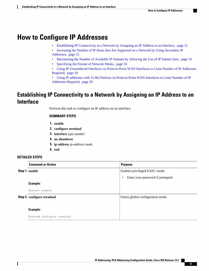
Establishing IP Connectivity to a Network by Assigning an IP Address to anInterface
Perform this task to configure an IP address on an interface.
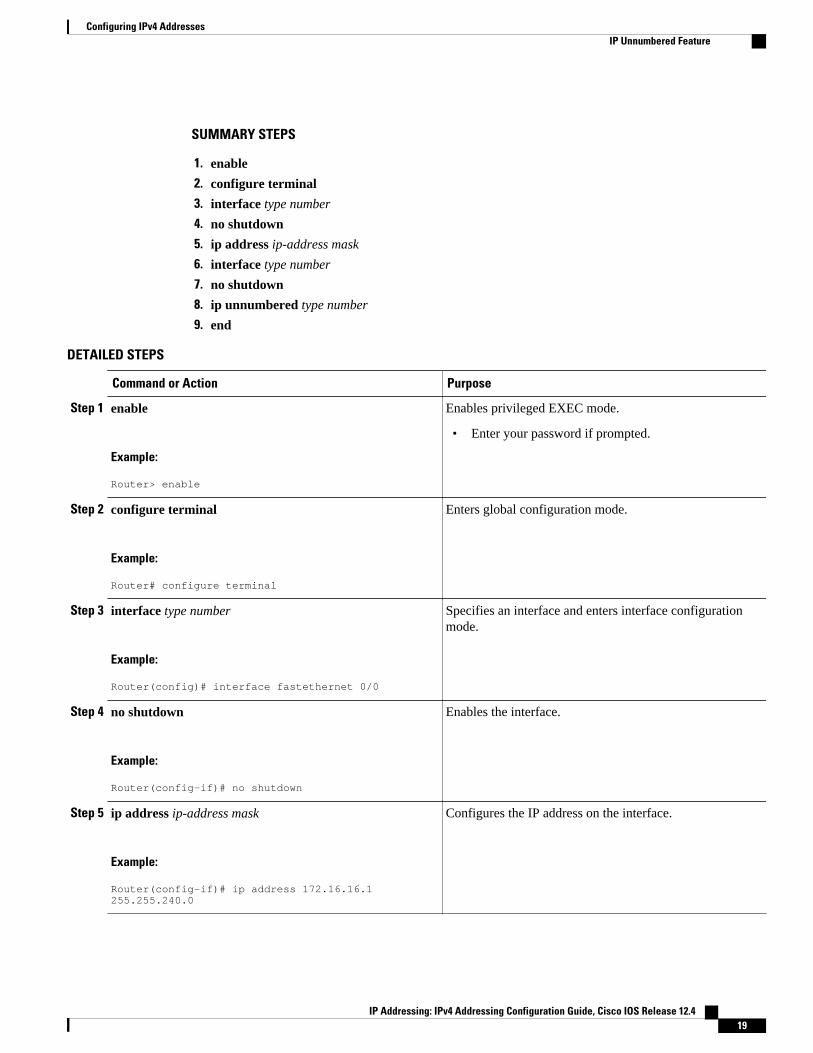
SUMMARY STEPS
1. enable
2. configure terminal
3. interface type number
4. no shutdown
5. ip address ip-address mask
6. end
DETAILED STEPS
Command or Action Purpose
Step 1 enable
Example:
Router> enable
Enables privileged EXEC mode.
• Enter your password if prompted.
Step 2 configure terminal
Example:
Router# configure terminal
Enters global configuration mode.
Establishing IP Connectivity to a Network by Assigning an IP Address to an InterfaceHow to Configure IP Addresses
IP Addressing: IPv4 Addressing Configuration Guide, Cisco IOS Release 12.4 11
Command or Action Purpose
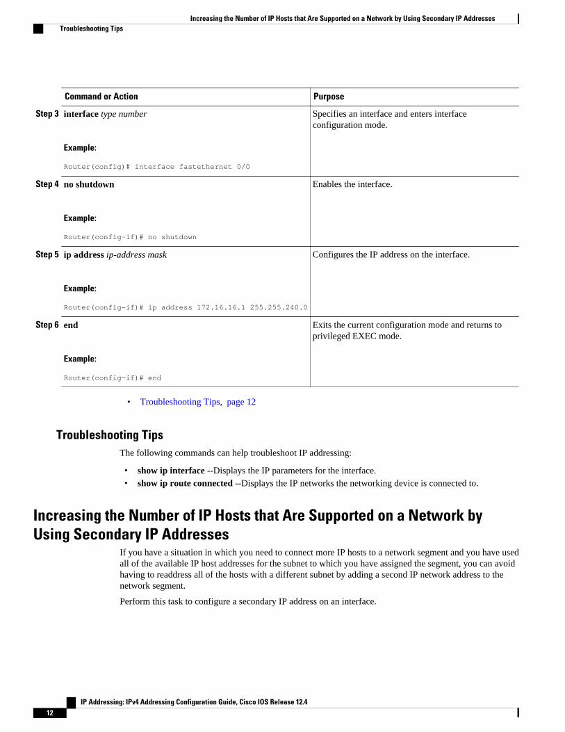
Step 3 interface type number
Example:
Router(config)# interface fastethernet 0/0
Specifies an interface and enters interfaceconfiguration mode.
Step 4 no shutdown
Example:
Router(config-if)# no shutdown
Enables the interface.
Step 5 ip address ip-address mask
Example:
Router(config-if)# ip address 172.16.16.1 255.255.240.0
Configures the IP address on the interface.
Step 6 end
Example:
Router(config-if)# end
Exits the current configuration mode and returns toprivileged EXEC mode.
• Troubleshooting Tips, page 12
Troubleshooting TipsThe following commands can help troubleshoot IP addressing:
• show ip interface --Displays the IP parameters for the interface.• show ip route connected --Displays the IP networks the networking device is connected to.
Increasing the Number of IP Hosts that Are Supported on a Network byUsing Secondary IP Addresses
If you have a situation in which you need to connect more IP hosts to a network segment and you have usedall of the available IP host addresses for the subnet to which you have assigned the segment, you can avoidhaving to readdress all of the hosts with a different subnet by adding a second IP network address to thenetwork segment.
Perform this task to configure a secondary IP address on an interface.
Increasing the Number of IP Hosts that Are Supported on a Network by Using Secondary IP Addresses Troubleshooting Tips
IP Addressing: IPv4 Addressing Configuration Guide, Cisco IOS Release 12.412
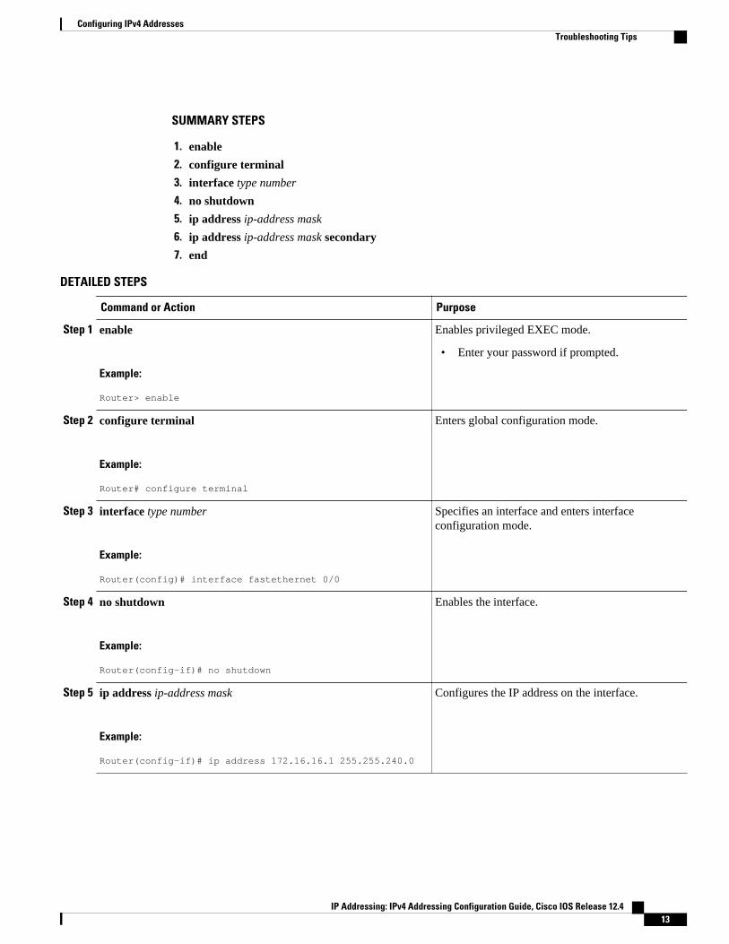
SUMMARY STEPS
1. enable
2. configure terminal
3. interface type number
4. no shutdown
5. ip address ip-address mask
6. ip address ip-address mask secondary
7. end
DETAILED STEPS
Command or Action Purpose
Step 1 enable
Example:
Router> enable
Enables privileged EXEC mode.
• Enter your password if prompted.
Step 2 configure terminal
Example:
Router# configure terminal
Enters global configuration mode.
Step 3 interface type number
Example:
Router(config)# interface fastethernet 0/0
Specifies an interface and enters interfaceconfiguration mode.
Step 4 no shutdown
Example:
Router(config-if)# no shutdown
Enables the interface.
Step 5 ip address ip-address mask
Example:
Router(config-if)# ip address 172.16.16.1 255.255.240.0
Configures the IP address on the interface.
Configuring IPv4 AddressesTroubleshooting Tips
IP Addressing: IPv4 Addressing Configuration Guide, Cisco IOS Release 12.4 13
Command or Action Purpose
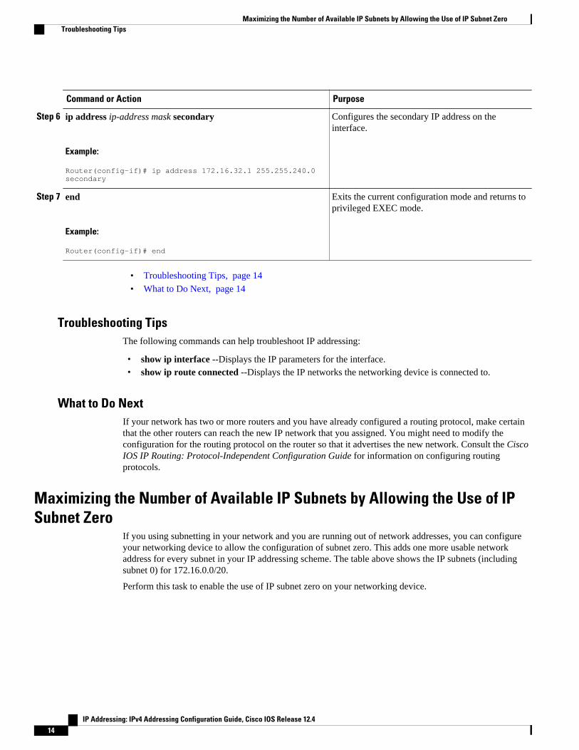
Step 6 ip address ip-address mask secondary
Example:
Router(config-if)# ip address 172.16.32.1 255.255.240.0 secondary
Configures the secondary IP address on theinterface.
Step 7 end
Example:
Router(config-if)# end
Exits the current configuration mode and returns toprivileged EXEC mode.
• Troubleshooting Tips, page 14
• What to Do Next, page 14
Troubleshooting TipsThe following commands can help troubleshoot IP addressing:
• show ip interface --Displays the IP parameters for the interface.• show ip route connected --Displays the IP networks the networking device is connected to.
What to Do NextIf your network has two or more routers and you have already configured a routing protocol, make certainthat the other routers can reach the new IP network that you assigned. You might need to modify theconfiguration for the routing protocol on the router so that it advertises the new network. Consult the CiscoIOS IP Routing: Protocol-Independent Configuration Guide for information on configuring routingprotocols.
Maximizing the Number of Available IP Subnets by Allowing the Use of IPSubnet Zero
If you using subnetting in your network and you are running out of network addresses, you can configureyour networking device to allow the configuration of subnet zero. This adds one more usable networkaddress for every subnet in your IP addressing scheme. The table above shows the IP subnets (includingsubnet 0) for 172.16.0.0/20.
Perform this task to enable the use of IP subnet zero on your networking device.
Maximizing the Number of Available IP Subnets by Allowing the Use of IP Subnet Zero Troubleshooting Tips
IP Addressing: IPv4 Addressing Configuration Guide, Cisco IOS Release 12.414
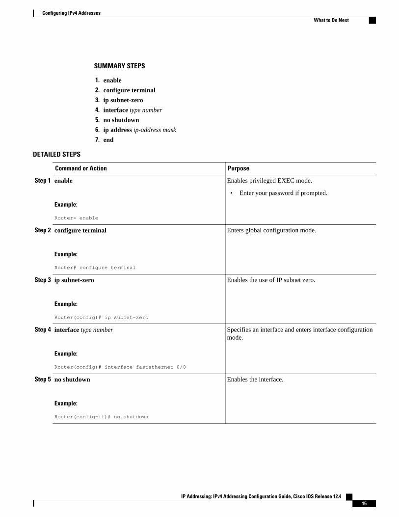
SUMMARY STEPS
1. enable
2. configure terminal
3. ip subnet-zero
4. interface type number
5. no shutdown
6. ip address ip-address mask
7. end
DETAILED STEPS
Command or Action Purpose
Step 1 enable
Example:
Router> enable
Enables privileged EXEC mode.
• Enter your password if prompted.
Step 2 configure terminal
Example:
Router# configure terminal
Enters global configuration mode.
Step 3 ip subnet-zero
Example:
Router(config)# ip subnet-zero
Enables the use of IP subnet zero.
Step 4 interface type number
Example:
Router(config)# interface fastethernet 0/0
Specifies an interface and enters interface configurationmode.
Step 5 no shutdown
Example:
Router(config-if)# no shutdown
Enables the interface.
Configuring IPv4 AddressesWhat to Do Next
IP Addressing: IPv4 Addressing Configuration Guide, Cisco IOS Release 12.4 15
Command or Action Purpose
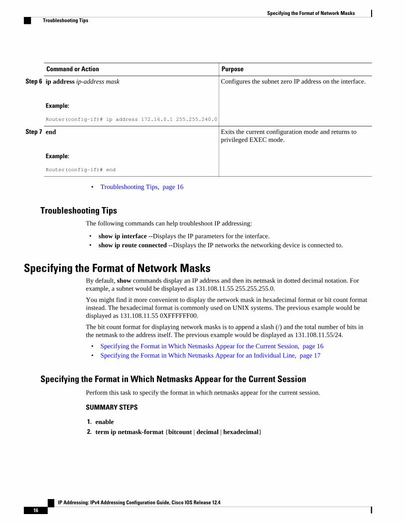
Step 6 ip address ip-address mask
Example:
Router(config-if)# ip address 172.16.0.1 255.255.240.0
Configures the subnet zero IP address on the interface.
Step 7 end
Example:
Router(config-if)# end
Exits the current configuration mode and returns toprivileged EXEC mode.
• Troubleshooting Tips, page 16
Troubleshooting TipsThe following commands can help troubleshoot IP addressing:
• show ip interface --Displays the IP parameters for the interface.• show ip route connected --Displays the IP networks the networking device is connected to.
Specifying the Format of Network MasksBy default, show commands display an IP address and then its netmask in dotted decimal notation. Forexample, a subnet would be displayed as 131.108.11.55 255.255.255.0.
You might find it more convenient to display the network mask in hexadecimal format or bit count formatinstead. The hexadecimal format is commonly used on UNIX systems. The previous example would bedisplayed as 131.108.11.55 0XFFFFFF00.
The bit count format for displaying network masks is to append a slash (/) and the total number of bits inthe netmask to the address itself. The previous example would be displayed as 131.108.11.55/24.
• Specifying the Format in Which Netmasks Appear for the Current Session, page 16
• Specifying the Format in Which Netmasks Appear for an Individual Line, page 17
Specifying the Format in Which Netmasks Appear for the Current SessionPerform this task to specify the format in which netmasks appear for the current session.
SUMMARY STEPS
1. enable
2. term ip netmask-format {bitcount | decimal | hexadecimal}
Specifying the Format of Network Masks Troubleshooting Tips
IP Addressing: IPv4 Addressing Configuration Guide, Cisco IOS Release 12.416
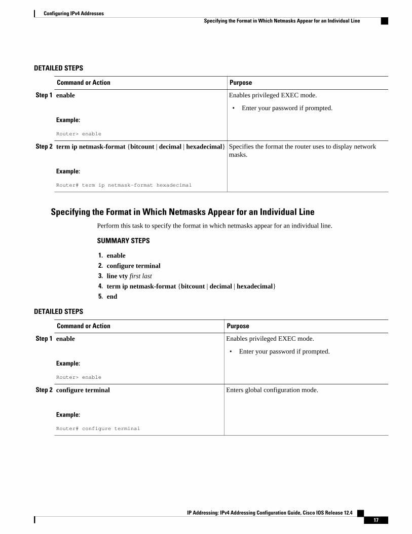
DETAILED STEPS
Command or Action Purpose
Step 1 enable
Example:
Router> enable
Enables privileged EXEC mode.
• Enter your password if prompted.
Step 2 term ip netmask-format {bitcount | decimal | hexadecimal}
Example:
Router# term ip netmask-format hexadecimal
Specifies the format the router uses to display networkmasks.
Specifying the Format in Which Netmasks Appear for an Individual LinePerform this task to specify the format in which netmasks appear for an individual line.
SUMMARY STEPS
1. enable
2. configure terminal
3. line vty first last
4. term ip netmask-format {bitcount | decimal | hexadecimal}
5. end
DETAILED STEPS
Command or Action Purpose
Step 1 enable
Example:
Router> enable
Enables privileged EXEC mode.
• Enter your password if prompted.
Step 2 configure terminal
Example:
Router# configure terminal
Enters global configuration mode.
Configuring IPv4 AddressesSpecifying the Format in Which Netmasks Appear for an Individual Line
IP Addressing: IPv4 Addressing Configuration Guide, Cisco IOS Release 12.4 17
Command or Action Purpose
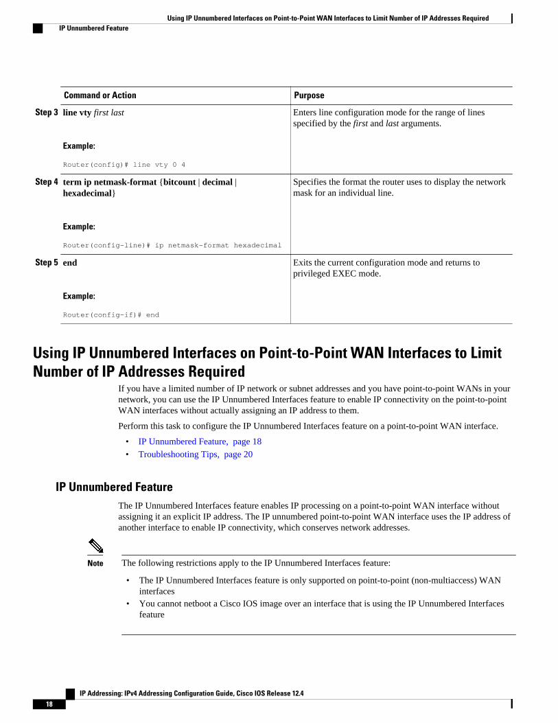
Step 3 line vty first last
Example:
Router(config)# line vty 0 4
Enters line configuration mode for the range of linesspecified by the first and last arguments.
Step 4 term ip netmask-format {bitcount | decimal |hexadecimal}
Example:
Router(config-line)# ip netmask-format hexadecimal
Specifies the format the router uses to display the networkmask for an individual line.
Step 5 end
Example:
Router(config-if)# end
Exits the current configuration mode and returns toprivileged EXEC mode.
Using IP Unnumbered Interfaces on Point-to-Point WAN Interfaces to LimitNumber of IP Addresses Required
If you have a limited number of IP network or subnet addresses and you have point-to-point WANs in yournetwork, you can use the IP Unnumbered Interfaces feature to enable IP connectivity on the point-to-pointWAN interfaces without actually assigning an IP address to them.
Perform this task to configure the IP Unnumbered Interfaces feature on a point-to-point WAN interface.
• IP Unnumbered Feature, page 18
• Troubleshooting Tips, page 20
IP Unnumbered FeatureThe IP Unnumbered Interfaces feature enables IP processing on a point-to-point WAN interface withoutassigning it an explicit IP address. The IP unnumbered point-to-point WAN interface uses the IP address ofanother interface to enable IP connectivity, which conserves network addresses.
Note The following restrictions apply to the IP Unnumbered Interfaces feature:
• The IP Unnumbered Interfaces feature is only supported on point-to-point (non-multiaccess) WANinterfaces
• You cannot netboot a Cisco IOS image over an interface that is using the IP Unnumbered Interfacesfeature
Using IP Unnumbered Interfaces on Point-to-Point WAN Interfaces to Limit Number of IP Addresses Required IP Unnumbered Feature
IP Addressing: IPv4 Addressing Configuration Guide, Cisco IOS Release 12.418
SUMMARY STEPS
1. enable
2. configure terminal
3. interface type number
4. no shutdown
5. ip address ip-address mask
6. interface type number
7. no shutdown
8. ip unnumbered type number
9. end
DETAILED STEPS
Command or Action Purpose
Step 1 enable
Example:
Router> enable
Enables privileged EXEC mode.
• Enter your password if prompted.
Step 2 configure terminal
Example:
Router# configure terminal
Enters global configuration mode.
Step 3 interface type number
Example:
Router(config)# interface fastethernet 0/0
Specifies an interface and enters interface configurationmode.
Step 4 no shutdown
Example:
Router(config-if)# no shutdown
Enables the interface.
Step 5 ip address ip-address mask
Example:
Router(config-if)# ip address 172.16.16.1 255.255.240.0
Configures the IP address on the interface.
Configuring IPv4 AddressesIP Unnumbered Feature
IP Addressing: IPv4 Addressing Configuration Guide, Cisco IOS Release 12.4 19
Command or Action Purpose
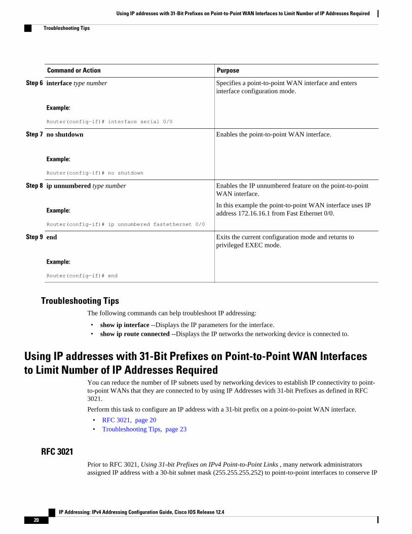
Step 6 interface type number
Example:
Router(config-if)# interface serial 0/0
Specifies a point-to-point WAN interface and entersinterface configuration mode.
Step 7 no shutdown
Example:
Router(config-if)# no shutdown
Enables the point-to-point WAN interface.
Step 8 ip unnumbered type number
Example:
Router(config-if)# ip unnumbered fastethernet 0/0
Enables the IP unnumbered feature on the point-to-pointWAN interface.
In this example the point-to-point WAN interface uses IPaddress 172.16.16.1 from Fast Ethernet 0/0.
Step 9 end
Example:
Router(config-if)# end
Exits the current configuration mode and returns toprivileged EXEC mode.
Troubleshooting TipsThe following commands can help troubleshoot IP addressing:
• show ip interface --Displays the IP parameters for the interface.• show ip route connected --Displays the IP networks the networking device is connected to.
Using IP addresses with 31-Bit Prefixes on Point-to-Point WAN Interfacesto Limit Number of IP Addresses Required
You can reduce the number of IP subnets used by networking devices to establish IP connectivity to point-to-point WANs that they are connected to by using IP Addresses with 31-bit Prefixes as defined in RFC3021.
Perform this task to configure an IP address with a 31-bit prefix on a point-to-point WAN interface.
• RFC 3021, page 20• Troubleshooting Tips, page 23
RFC 3021Prior to RFC 3021, Using 31-bit Prefixes on IPv4 Point-to-Point Links , many network administratorsassigned IP address with a 30-bit subnet mask (255.255.255.252) to point-to-point interfaces to conserve IP
Using IP addresses with 31-Bit Prefixes on Point-to-Point WAN Interfaces to Limit Number of IP Addresses Required
Troubleshooting Tips
IP Addressing: IPv4 Addressing Configuration Guide, Cisco IOS Release 12.420
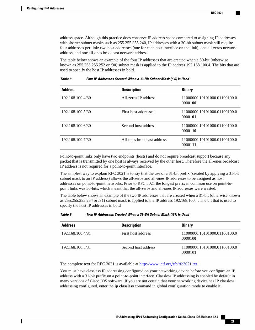
address space. Although this practice does conserve IP address space compared to assigning IP addresseswith shorter subnet masks such as 255.255.255.240, IP addresses with a 30-bit subnet mask still requirefour addresses per link: two host addresses (one for each host interface on the link), one all-zeros networkaddress, and one all-ones broadcast network address.
The table below shows an example of the four IP addresses that are created when a 30-bit (otherwiseknown as 255.255.255.252 or /30) subnet mask is applied to the IP address 192.168.100.4. The bits that areused to specify the host IP addresses in bold.
Table 8 Four IP Addresses Created When a 30-Bit Subnet Mask (/30) Is Used
Address Description Binary
192.168.100.4/30 All-zeros IP address 11000000.10101000.01100100.00000100
192.168.100.5/30 First host addresses 11000000.10101000.01100100.00000101
192.168.100.6/30 Second host address 11000000.10101000.01100100.00000110
192.168.100.7/30 All-ones broadcast address 11000000.10101000.01100100.00000111
Point-to-point links only have two endpoints (hosts) and do not require broadcast support because anypacket that is transmitted by one host is always received by the other host. Therefore the all-ones broadcastIP address is not required for a point-to-point interface.
The simplest way to explain RFC 3021 is to say that the use of a 31-bit prefix (created by applying a 31-bitsubnet mask to an IP address) allows the all-zeros and all-ones IP addresses to be assigned as hostaddresses on point-to-point networks. Prior to RFC 3021 the longest prefix in common use on point-to-point links was 30-bits, which meant that the all-zeros and all-ones IP addresses were wasted.
The table below shows an example of the two IP addresses that are created when a 31-bit (otherwise knownas 255.255.255.254 or /31) subnet mask is applied to the IP address 192.168.100.4. The bit that is used tospecify the host IP addresses in bold
Table 9 Two IP Addresses Created When a 31-Bit Subnet Mask (/31) Is Used
Address Description Binary
192.168.100.4/31 First host address 11000000.10101000.01100100.00000100
192.168.100.5/31 Second host address 11000000.10101000.01100100.00000101
The complete text for RFC 3021 is available at http://www.ietf.org/rfc/rfc3021.txt .
You must have classless IP addressing configured on your networking device before you configure an IPaddress with a 31-bit prefix on a point-to-point interface. Classless IP addressing is enabled by default inmany versions of Cisco IOS software. If you are not certain that your networking device has IP classlessaddressing configured, enter the ip classless command in global configuration mode to enable it.
Configuring IPv4 AddressesRFC 3021
IP Addressing: IPv4 Addressing Configuration Guide, Cisco IOS Release 12.4 21
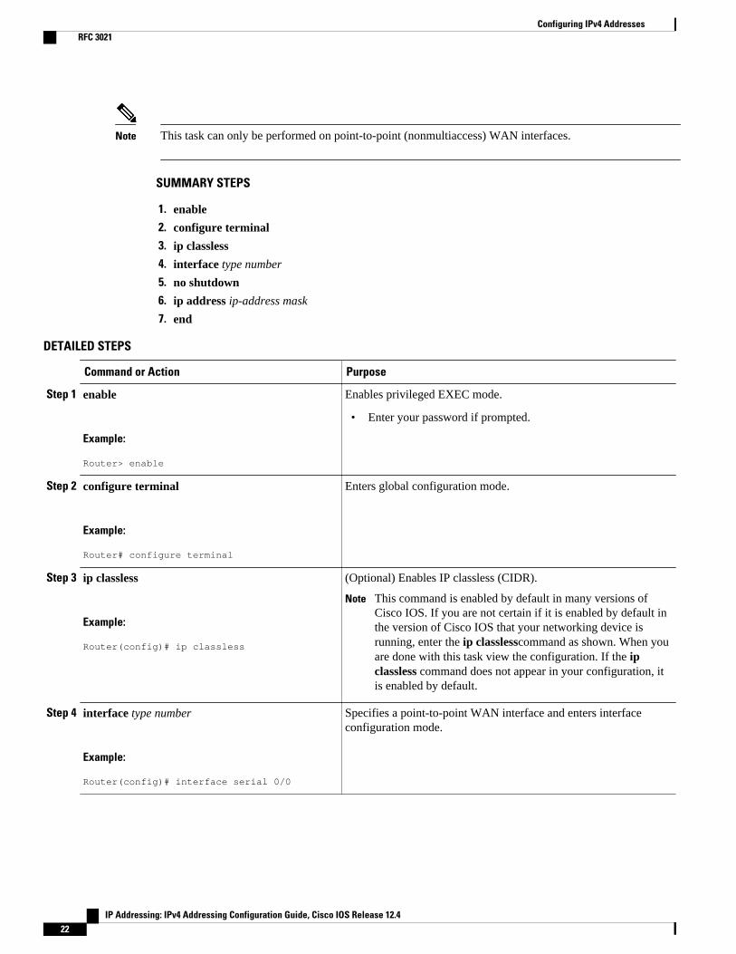
Note This task can only be performed on point-to-point (nonmultiaccess) WAN interfaces.
SUMMARY STEPS
1. enable
2. configure terminal
3. ip classless
4. interface type number
5. no shutdown
6. ip address ip-address mask
7. end
DETAILED STEPS
Command or Action Purpose
Step 1 enable
Example:
Router> enable
Enables privileged EXEC mode.
• Enter your password if prompted.
Step 2 configure terminal
Example:
Router# configure terminal
Enters global configuration mode.
Step 3 ip classless
Example:
Router(config)# ip classless
(Optional) Enables IP classless (CIDR).
Note This command is enabled by default in many versions ofCisco IOS. If you are not certain if it is enabled by default inthe version of Cisco IOS that your networking device isrunning, enter the ip classlesscommand as shown. When youare done with this task view the configuration. If the ipclassless command does not appear in your configuration, itis enabled by default.
Step 4 interface type number
Example:
Router(config)# interface serial 0/0
Specifies a point-to-point WAN interface and enters interfaceconfiguration mode.
Configuring IPv4 Addresses RFC 3021
IP Addressing: IPv4 Addressing Configuration Guide, Cisco IOS Release 12.422
Command or Action Purpose
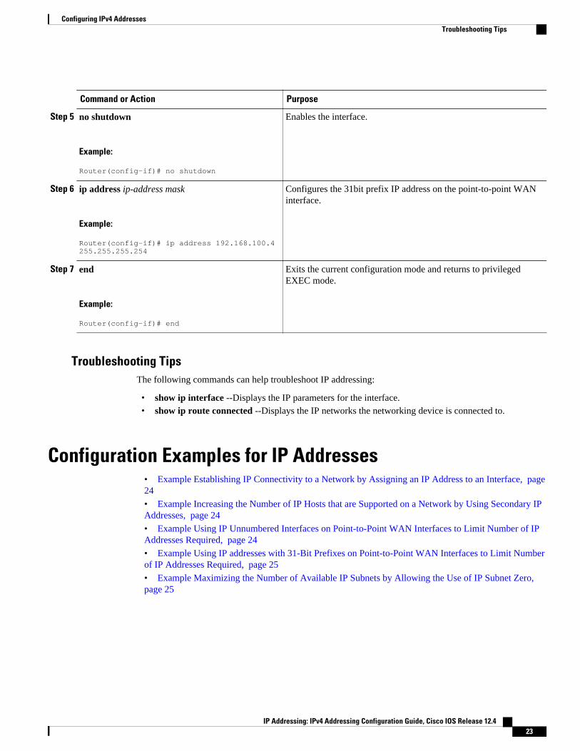
Step 5 no shutdown
Example:
Router(config-if)# no shutdown
Enables the interface.
Step 6 ip address ip-address mask
Example:
Router(config-if)# ip address 192.168.100.4 255.255.255.254
Configures the 31bit prefix IP address on the point-to-point WANinterface.
Step 7 end
Example:
Router(config-if)# end
Exits the current configuration mode and returns to privilegedEXEC mode.
Troubleshooting TipsThe following commands can help troubleshoot IP addressing:
• show ip interface --Displays the IP parameters for the interface.• show ip route connected --Displays the IP networks the networking device is connected to.
Configuration Examples for IP Addresses• Example Establishing IP Connectivity to a Network by Assigning an IP Address to an Interface, page24
• Example Increasing the Number of IP Hosts that are Supported on a Network by Using Secondary IPAddresses, page 24
• Example Using IP Unnumbered Interfaces on Point-to-Point WAN Interfaces to Limit Number of IPAddresses Required, page 24
• Example Using IP addresses with 31-Bit Prefixes on Point-to-Point WAN Interfaces to Limit Numberof IP Addresses Required, page 25
• Example Maximizing the Number of Available IP Subnets by Allowing the Use of IP Subnet Zero, page 25
Configuring IPv4 AddressesTroubleshooting Tips
IP Addressing: IPv4 Addressing Configuration Guide, Cisco IOS Release 12.4 23
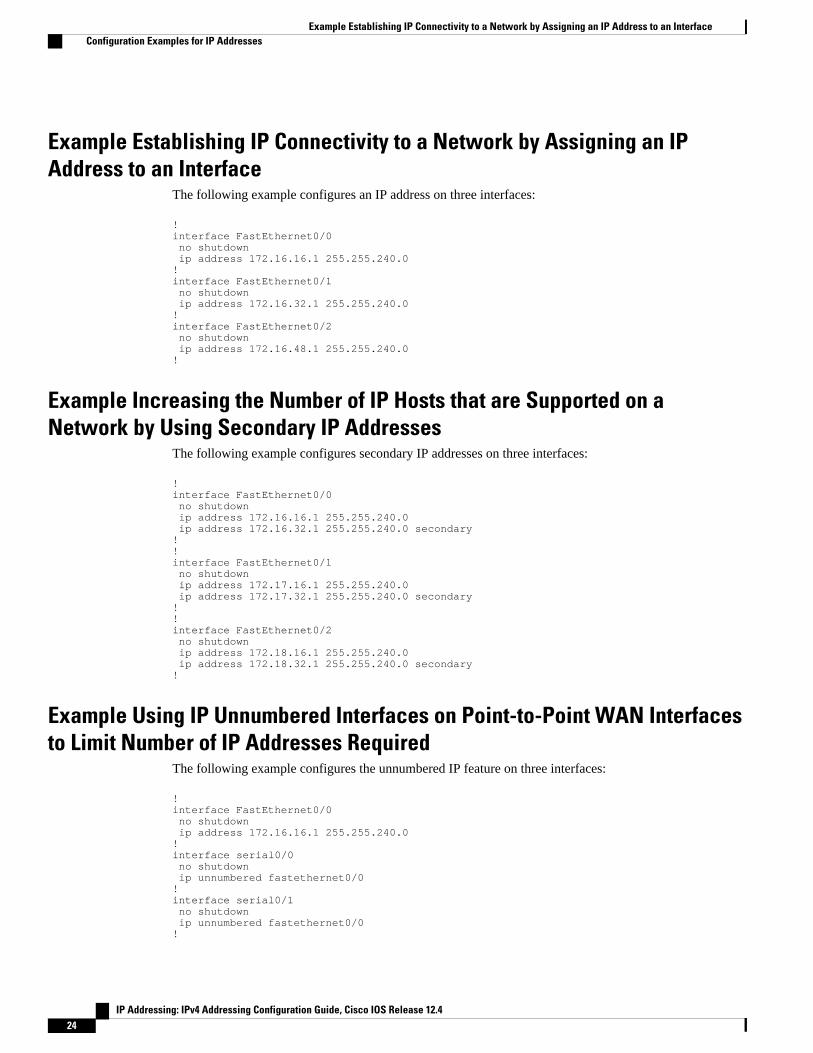
Example Establishing IP Connectivity to a Network by Assigning an IPAddress to an Interface
The following example configures an IP address on three interfaces:
!interface FastEthernet0/0 no shutdown ip address 172.16.16.1 255.255.240.0!interface FastEthernet0/1 no shutdown ip address 172.16.32.1 255.255.240.0!interface FastEthernet0/2 no shutdown ip address 172.16.48.1 255.255.240.0!
Example Increasing the Number of IP Hosts that are Supported on aNetwork by Using Secondary IP Addresses
The following example configures secondary IP addresses on three interfaces:
!interface FastEthernet0/0 no shutdown ip address 172.16.16.1 255.255.240.0 ip address 172.16.32.1 255.255.240.0 secondary!!interface FastEthernet0/1 no shutdown ip address 172.17.16.1 255.255.240.0 ip address 172.17.32.1 255.255.240.0 secondary!!interface FastEthernet0/2 no shutdown ip address 172.18.16.1 255.255.240.0 ip address 172.18.32.1 255.255.240.0 secondary!
Example Using IP Unnumbered Interfaces on Point-to-Point WAN Interfacesto Limit Number of IP Addresses Required
The following example configures the unnumbered IP feature on three interfaces:
!interface FastEthernet0/0 no shutdown ip address 172.16.16.1 255.255.240.0!interface serial0/0 no shutdown ip unnumbered fastethernet0/0!interface serial0/1 no shutdown ip unnumbered fastethernet0/0!
Example Establishing IP Connectivity to a Network by Assigning an IP Address to an Interface Configuration Examples for IP Addresses
IP Addressing: IPv4 Addressing Configuration Guide, Cisco IOS Release 12.424
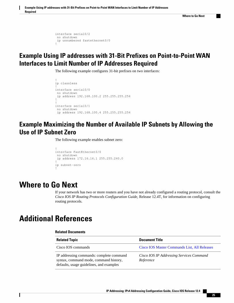
interface serial0/2 no shutdown ip unnumbered fastethernet0/0!
Example Using IP addresses with 31-Bit Prefixes on Point-to-Point WANInterfaces to Limit Number of IP Addresses Required
The following example configures 31-bit prefixes on two interfaces:
!ip classless!interface serial0/0 no shutdown ip address 192.168.100.2 255.255.255.254!!interface serial0/1 no shutdown ip address 192.168.100.4 255.255.255.254
Example Maximizing the Number of Available IP Subnets by Allowing theUse of IP Subnet Zero
The following example enables subnet zero:
!interface FastEthernet0/0 no shutdown ip address 172.16.16.1 255.255.240.0!ip subnet-zero!
Where to Go NextIf your network has two or more routers and you have not already configured a routing protocol, consult theCisco IOS IP Routing Protocols Configuration Guide, Release 12.4T, for information on configuringrouting protocols.
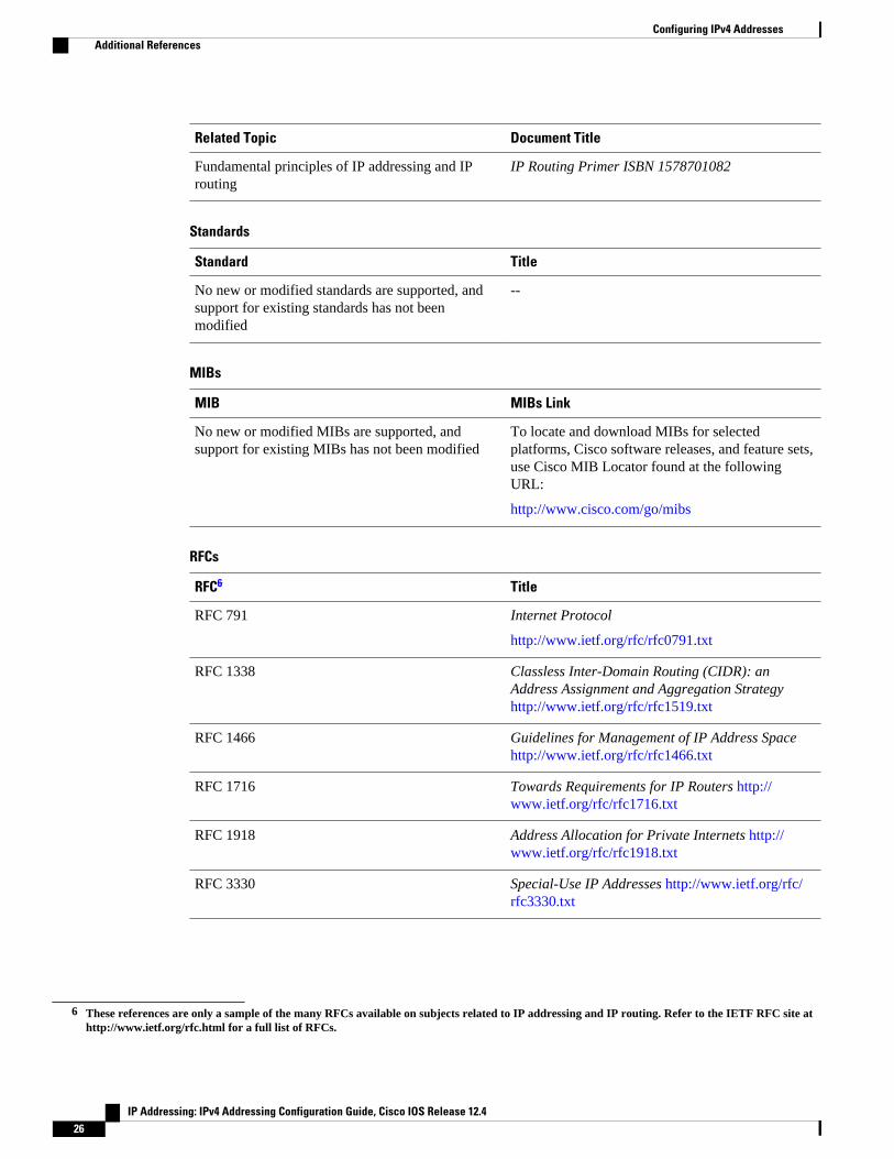
Additional ReferencesRelated Documents
Related Topic Document Title
Cisco IOS commands Cisco IOS Master Commands List, All Releases
IP addressing commands: complete commandsyntax, command mode, command history,defaults, usage guidelines, and examples
Cisco IOS IP Addressing Services CommandReference
Example Using IP addresses with 31-Bit Prefixes on Point-to-Point WAN Interfaces to Limit Number of IP AddressesRequired
Where to Go Next
IP Addressing: IPv4 Addressing Configuration Guide, Cisco IOS Release 12.4 25
Related Topic Document Title
Fundamental principles of IP addressing and IProuting
IP Routing Primer ISBN 1578701082
Standards
Standard Title
No new or modified standards are supported, andsupport for existing standards has not beenmodified
--
MIBs
MIB MIBs Link
No new or modified MIBs are supported, andsupport for existing MIBs has not been modified
To locate and download MIBs for selectedplatforms, Cisco software releases, and feature sets,use Cisco MIB Locator found at the followingURL:
http://www.cisco.com/go/mibs
RFCs
RFC6 Title
RFC 791 Internet Protocol
http://www.ietf.org/rfc/rfc0791.txt
RFC 1338 Classless Inter-Domain Routing (CIDR): anAddress Assignment and Aggregation Strategy http://www.ietf.org/rfc/rfc1519.txt
RFC 1466 Guidelines for Management of IP Address Space http://www.ietf.org/rfc/rfc1466.txt
RFC 1716 Towards Requirements for IP Routers http://www.ietf.org/rfc/rfc1716.txt
RFC 1918 Address Allocation for Private Internets http://www.ietf.org/rfc/rfc1918.txt
RFC 3330 Special-Use IP Addresses http://www.ietf.org/rfc/rfc3330.txt
6 These references are only a sample of the many RFCs available on subjects related to IP addressing and IP routing. Refer to the IETF RFC site athttp://www.ietf.org/rfc.html for a full list of RFCs.
Configuring IPv4 Addresses Additional References
IP Addressing: IPv4 Addressing Configuration Guide, Cisco IOS Release 12.426
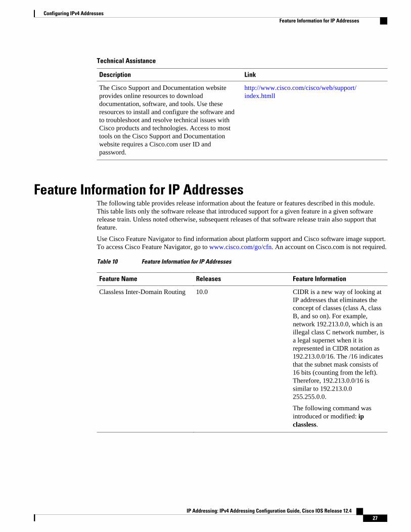
Technical Assistance
Description Link
The Cisco Support and Documentation websiteprovides online resources to downloaddocumentation, software, and tools. Use theseresources to install and configure the software andto troubleshoot and resolve technical issues withCisco products and technologies. Access to mosttools on the Cisco Support and Documentationwebsite requires a Cisco.com user ID andpassword.
http://www.cisco.com/cisco/web/support/index.htmll
Feature Information for IP AddressesThe following table provides release information about the feature or features described in this module.This table lists only the software release that introduced support for a given feature in a given softwarerelease train. Unless noted otherwise, subsequent releases of that software release train also support thatfeature.
Use Cisco Feature Navigator to find information about platform support and Cisco software image support.To access Cisco Feature Navigator, go to www.cisco.com/go/cfn. An account on Cisco.com is not required.
Table 10 Feature Information for IP Addresses
Feature Name Releases Feature Information
Classless Inter-Domain Routing 10.0 CIDR is a new way of looking atIP addresses that eliminates theconcept of classes (class A, classB, and so on). For example,network 192.213.0.0, which is anillegal class C network number, isa legal supernet when it isrepresented in CIDR notation as192.213.0.0/16. The /16 indicatesthat the subnet mask consists of16 bits (counting from the left).Therefore, 192.213.0.0/16 issimilar to 192.213.0.0255.255.0.0.
The following command wasintroduced or modified: ipclassless.
Configuring IPv4 AddressesFeature Information for IP Addresses
IP Addressing: IPv4 Addressing Configuration Guide, Cisco IOS Release 12.4 27
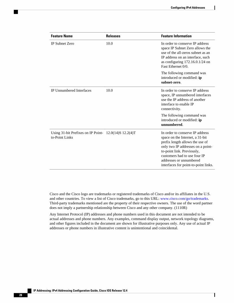
Feature Name Releases Feature Information
IP Subnet Zero 10.0 In order to conserve IP addressspace IP Subnet Zero allows theuse of the all-zeros subnet as anIP address on an interface, suchas configuring 172.16.0.1/24 onFast Ethernet 0/0.
The following command wasintroduced or modified: ipsubnet-zero.
IP Unnumbered Interfaces 10.0 In order to conserve IP addressspace, IP unnumbered interfacesuse the IP address of anotherinterface to enable IPconnectivity.
The following command wasintroduced or modified: ipunnumbered.
Using 31-bit Prefixes on IP Point-to-Point Links
12.0(14)S 12.2(4)T In order to conserve IP addressspace on the Internet, a 31-bitprefix length allows the use ofonly two IP addresses on a point-to-point link. Previously,customers had to use four IPaddresses or unnumberedinterfaces for point-to-point links.
Cisco and the Cisco logo are trademarks or registered trademarks of Cisco and/or its affiliates in the U.S.and other countries. To view a list of Cisco trademarks, go to this URL: www.cisco.com/go/trademarks.Third-party trademarks mentioned are the property of their respective owners. The use of the word partnerdoes not imply a partnership relationship between Cisco and any other company. (1110R)
Any Internet Protocol (IP) addresses and phone numbers used in this document are not intended to beactual addresses and phone numbers. Any examples, command display output, network topology diagrams,and other figures included in the document are shown for illustrative purposes only. Any use of actual IPaddresses or phone numbers in illustrative content is unintentional and coincidental.
Configuring IPv4 Addresses
IP Addressing: IPv4 Addressing Configuration Guide, Cisco IOS Release 12.428