i.o.m. installation, operation and maintenance cpxv cpxrv ma… · i.o.m. installation, operation...
TRANSCRIPT

®
Flowserve Pump Division
I.O.M. Installation, Operation and Maintenance
IDP® PumpsModels CPXV & CPXRV
VERTICAL SUMP PUMPS
Instruction Manual C942KH001 - 01/03

INSTRUCTION MANUAL CPXV & CPXRV ENGLISH C942KH001 - 12/02
®
2
INTRODUCTION
Flowserve
Flowserve's products and brands are the leading names in their fields: the CPX range of processpumps specifically focus on demanding chemical process applications. The pumps are manufacturedat modern facilities, utilising state of art equipment and sophisticated quality control techniques.Flowserve is proud of earning preferred supplier status to many of world's leading processingcompanies. Engineered, manufactured, sold and serviced to ISO 9001 quality certification, Flowservepumps are truly world class products.
With more than 120 years of experience in servicing the needs of world-wide process industries,Flowserve has become the unchallenged leader in hydraulic design engineering, materials expertiseand application know-how. Committed to continuous quality improvement, Flowserve controls thecomplete product life cycle - from application engineering, design, melting and casting, to cellularmanufacturing, to assembly and testing, to the supply of aftermarket products, repair and diagnosticservices.
Flowserve is on hand to provide technical support and special services specific to the needs of itscustomers.
CopyrightAll rights reserved. No part of this manual may be reproduced, stored in a retrieval system ortransmitted in any form or by any means without prior permission of Flowserve Pump Division.
CE Mark SystemIt is a legal requirement that machinery and equipment put into service within the European Unionshall conform with the applicable European Union Directives covering Machinery and, whereapplicable, Low Voltage Equipment, Electromagnetic Compatibility (EMC), Pressure EquipmentDirective (PED) and Equipment for Potentially Explosive Atmospheres (ATEX).
Where applicable the European Union Directives cover important Safety aspects relating tomachinery and equipment and the satisfactory provision of technical documents and safetyinstructions. This document incorporates information relevant to these Directives.
& The Manual should be read prior to installing, operating, using and maintaining theequipment. The equipment must not be put into service until all the conditions relating tosafety noted in the Manual have been met.
DisclaimerFlowserve manufactures products to exacting International Quality Management System Standards(ISO 9001). Genuine parts and accessories have been designed, tested and incorporated into theproducts to ensure their continued product quality and performance in use. As Flowserve cannottest parts and accessories sourced from other vendors the incorrect incorporation of such parts andaccessories may adversely affect the performance and safety features of the products. The failureto properly select, install or use authorised Flowserve parts and accessories is considered to bemisuse. Damage or failure caused by misuse is not covered by Flowserve's warranty. In addition,any modification of Flowserve products or removal of original components may impair the safety ofthese products in their use.

INSTRUCTION MANUAL CPXV & CPXRV ENGLISH C942KH001 - 12/02
®
3
1 NAMEPLATE & WARNING LABELS
1.1 NameplateFor details of nameplate, see the Declaration of conformity.
1.2 Warning labels
Oil lubricated units only.

INSTRUCTION MANUAL CPXV & CPXRV ENGLISH C942KH001 - 12/02
®
4
2 SAFETY
2.1 Duty conditionsThis pump has been selected to meet the duty andservice conditions advised on your order. Theacknowledgement of these conditions has been sentseparately to the Purchaser. A copy should be keptwith this manual.
If there is any doubt as to the suitability of the pump forthe application intended, contact Flowserve for advice,quoting the pump serial number.
2.2 Safety actionAlways co-ordinate repair activity with operationspersonnel, and follow all plant safety requirements andapplicable safety and health laws/regulations.
THIS IS A SUMMARY OF CONDITIONS ANDACTIONS TO PREVENT INJURY TO PERSONNELAND DAMAGE TO EQUIPMENT.
This sign indicates safety instructions wherenon-compliance would affect personal safety.
This symbol indicates electrical safetyinstructions where non-compliance would affectpersonal safety.
This symbol indicates safetyinstructions where non-compliance would affect thesafe operation or protection of the pump or pump unit.
2.2.1 PREVENT EXCESSIVEEXTERNAL PIPE LOADDo not use pump as a support for piping. Do notmount expansion joints so that their force, due tointernal pressure, acts on the pump flange.
2.2.2 ONLY CHECK DIRECTION OFMOTOR ROTATION WITH COUPLINGELEMENT/PINS REMOVEDStarting in reverse direction of rotation will damage thepump.
2.2.3 START THE PUMP WITHOUTLET VALVE CLOSEDThis is recommended to avoid the risk of overloadingand damaging the pump motor at full flow. Pumpsmay be started with the valve open only oninstallations where this situation cannot occur.
2.2.4 ENSURE CORRECTLUBRICATION(See: Making ready for operation - Lubrication. )
2.2.5 NEVER RUN THE PUMP DRY
2.2.6 INLET VALVES TO BE FULLYOPEN WHEN PUMP IS RUNNINGRunning the pump at zero flow or below therecommended minimum flow continuously will causethe shaft, packing or mechanical seal to run hot and failwithin a short time.
2.2.7 DO NOT RUN THE PUMP ATABNORMALLY HIGH OR LOW FLOW RATESOperating at a flow rate higher than normal or at a flowrate with no back pressure on the pump may overloadthe motor and cause cavitation. Low flow rates maycause a reduction in pump/bearing life, overheating ofthe pump, instability and cavitation/vibration.
2.2.8 NEVER DO MAINTENANCE WORKWHILST THE UNIT IS CONNECTED TO POWER
2.2.9 NEVER APPLY HEAT TO REMOVEIMPELLERTrapped lubricant or vapour could cause an explosion.
2.2.10 HANDLING COMPONENTSMany precision parts have sharp corners and the wearingof appropriate safety gloves and equipment is requiredwhen handling these components. To lift heavy piecesabove 30kg (66lbs) use a crane corresponding to themass and in accordance with current local regulations.
2.2.11 DRAIN PUMP AND ISOLATE PIPEWORKBEFORE DISMANTLING THE PUMPThe appropriate safety precautions should be takenwhere the pumped liquids are hazardous.
2.2.12 FLUORO-ELASTOMERS (when fitted tohigh temperature units).When a pump has experienced temperatures over250°C (482ºF), partial decomposition of fluoro-elastomers (eg viton) will occur. In this condition theseare extremely dangerous and skin contact must beavoided.
2.2.13 THERMAL SHOCKRapid changes in the temperature of the liquid withinthe pump can cause thermal shock, which can result indamage or breakage of components. Thermal shockshould be avoided, particularly so where the materialof the pump is not resistant to such loading.
2.2.14 HOT (and cold) PARTSIf hot or freezing components or auxiliary heatingsupplies can present a danger to operators, they mustbe shielded to avoid accidental contact. If completeprotection is not possible, machine access must belimited to maintenance staff only. Note: drive motorsand bearings may be hot.
IF THE TEMPERATURE IS GREATER THAN 80°C(175°F) OR BELOW 5°C (20°F), A VISUALWARNING INDICATOR SUCH AS A WARNINGPLATE MUST BE PLACED CLEARLY ON THEEQUIPMENT.

INSTRUCTION MANUAL CPXV & CPXRV ENGLISH C942KH001 - 12/02
®
5
2.2.15 HAZARDOUS LIQUIDSWhen the pump is handling hazardous liquids caremust be taken to avoid liquid contact using theappropriate health and safety procedures. Pumplocation and personnel access/training should considerand address these site dangers.
2.3 Potentially explosive atmospheresAlways check that the driver, drive coupling assemblyand pump equipment are suitably rated and/or certifiedfor the classification of the specific atmosphere inwhich they are to be installed. See section 17,Certification.

INSTRUCTION MANUAL CPXV & CPXRV ENGLISH C942KH001 - 12/02
®
6
3 CONTENTSPAGE
INTRODUCTION 2
1 NAMEPLATE & WARNING LABELS 3
2 SAFETYDuty conditions 4Safety action 4Potentially explosive atmospheres 5
3 CONTENTS 6
4 PUMP TECHNICAL DATAPerformance 7Noise level 7Pressure limits 7Flange loads 7Ambient temperature 7Pump lubricants 8
5 PRODUCT DESCRIPTIONGeneral 8Pump casing 8Impeller 8Shaft 8Bearing housing 8Pump bearings and lubrication 9Soleplate seal 9Driver 9Accessories 9
6 STORAGE 9
7 INSTALLATIONUnpacking and inspection 9Handling 9Location 9Foundation 9Grouting 9Electrical connections 9Pipework connections 10Final piping check 10Auxiliary piping 10
8 MAKING READY FOR OPERATIONLubrication 10Direction of rotation 10Guarding 10Open impeller clearance 10Primary and auxiliary supplies 11Filling and priming 11
9 STARTING THE PUMP 11
10 RUNNINGPumps fitted with packed glands 11Pumps fitted with mechanical seals 11Stop/start frequency 11
PAGE
11 STOPPING AND SHUTDOWN 11
12 PREVENTATIVE MAINTENANCE ANDSERVICING
Maintenance schedule 11Routine inspection (daily/weekly) 11Periodic inspection (6 monthly) 12Lubrication data 12Gland packing 12Mechanical seals 12Setting impeller clearance 12
13 DISMANTLING AND ASSEMBLYDismantling 13Examination of parts 13Assembly 14Casing and seal housing screw torque 15
14 SPARE PARTSOrdering of spares 16Storage of spares 16Recommended spares 16
15 SUPPLEMENTARY INSTRUCTIONMANUALS 16
16 CHANGE NOTES 16
17 CERTIFICATION 16
18 GENERAL ARRANGEMENT DRAWING 16
19 OPERATING DIFFICULTIES 17
20 SECTIONAL ARRANGEMENTDRAWINGS AND PARTS LISTS 18-22
21 PARTS INTERCHANGEABILITY 23

INSTRUCTION MANUAL CPXV & CPXRV ENGLISH C942KH001 - 12/02
®
7
4 PUMP TECHNICAL DATA
4.1 PerformanceFor performance parameters see the paragraph onSafety - Duty conditions. When specified by thecontract, performance data has been suppliedseparately to the purchaser and should be obtainedand retained with this manual if required.
4.2 Noise levelWhen pump noise level exceeds 85dBA attention mustbe given to prevailing Health and Safety Legislation, tolimit the exposure of plant operating personnel to thenoise. The usual approach is to control exposure timeto the noise or to enclose the machine to reduceemitted sound.
You may have already specified a limiting noise levelwhen the equipment was ordered, however if nonoise requirements were defined then machinesabove a certain power level will exceed 85dBA.
Pump noise level is dependent on a number of factors- the type of motor fitted, the operating capacity,pipework design and acoustic characteristics of thebuilding. The levels specified in the table below areestimated and not guaranteed.
The dBA values are based on the noisiest ungearedelectric motors that are likely to be encountered. Theyare Sound Pressure levels at 1m (3.3ft) from the directlydriven pump, for "free field over a reflecting plane".
If a pump unit only has been purchased, for fittingwith your own driver, then the "pump only" noiselevels from the table should be combined with thelevel for the driver obtained from the supplier.Consult a Noise Specialist for this calculation.
For units driven by equipment other than electricmotors or units contained within enclosures, see theaccompanying information sheets and manuals.
4.3 Pressure limitsThe operating pressure has been selected to meetyour specified requirements. See the paragraph onSafety - Duty conditions for details.
The pressure and temperature operating limits for theflanges are in accordance with the relevant Nationalor International standards unless advised otherwise.
4.4 Flange loadsThe permissible flange loading is dependent on anumber of factors such as dimensions, flange rating,pressure, temperature, material, pump configuration,etc. The recommendations contained in the section onpipework connections should be followed to eliminatethese loads.
When requested the permissible flange loading willhave been supplied separately to the purchaser andshould be obtained and retained with this manual.
If in doubt contact Flowserve for information.
4.5 Ambient temperatureThese pumps are generally fitted with TEFC motorswith an ambient temperature limit of 40°C (104°F).Specific pumps may be fitted with motors to suit clients'requirements with other ambient temperature limits -see motor nameplate for details.
3550 rpm 2900 rpm 1750 rpm 1450 rpmMotor size
kW (hp)
Pump &motordBA
PumponlydBA
Pump &motordBA
PumponlydBA
Pump &motordBA
PumponlydBA
Pump &motordBA
PumponlydBA
<0.55 (<0.75) 71 66 64 62 64 62 63 620.75 (1) 74 66 67 62 67 62 63 621.1 (1.5) 74 68 67 64 67 64 65 641.5 (2) 77 70 70 66 70 66 66 662.2 (3) 78 72 71 68 71 68 68 683 (4) 81 74 74 70 74 74 70 704 (5) 82 75 75 71 75 75 71 71
5.5 (7.5) 90 77 83 73 76 75 72 717.5 (10) 90 78 83 74 77 76 73 7211 (15) 91 80 84 76 78 77 74 7315 (20) 92 83 85 79 80 79 76 75
18.5 (25) 92 83 85 79 80 79 76 7522 (30) 92 83 85 79 81 79 77 7530 (40) 100 85 93 81 84 80 80 7637 (50) 100 86 93 82 84 80 80 7645 (60) 100 87 93 83 84 80 80 7655 (75) 102 88 95 84 86 81 82 7775 (100) 100 90 95 86 88 81 83 7890 (120) 97 90 92 86 90 81 85 78110 (150) 100 91 95 87 91 83 86 79150 (200) 101 92 96 88 91 83 86 79

INSTRUCTION MANUAL CPXV & CPXRV ENGLISH C942KH001 - 12/02
®
8
4.6 Pump lubricants
4.6.1 Recommended oil lubricantsOil Splash lubrication Force feed lubrication
Viscositymm²/s 40ºC 32 68 46
Temp. maximumºC (ºF) 65 (149) 80 (176) -
Cen
tifug
al p
ump
lub
rica
tio
n
Designationaccording to
DIN51502 ISO VGHL/HLP 32 HL/HLP 68 HL/HLP 46
BPBP Energol HL32
BP Energol HLP32BP Energol HL68
BP Energol HLP68BP Energol HL46
BP Energol HLP46
DEAAnstron HL32Anstron HLP32
Anstron HL68Anstron HLP68
Anstron HL46Anstron HLP46
Elf
OLNA 32HYDRELEF 32TURBELF 32
ELFOLNA DS32
TURBELF SA68
ELFOLNA DS68
TURBELF SA46
ELFOLNA DS46
EssoTERESSO 32
NUTO H32TERESSO 68
NUTO H68TERESSO 46
NUTO H46
Mobil Mobil DTE oil lightMobil DTE13MobilDTE24
Mobil DTE oil heavy medium
Mobil DTE26
Mobil DTE oil mediumMobil DTE15MMobil DTE25
Q8Q8 Verdi 32Q8 Haydn 32
Q8 Verdi 68Q8 Haydn 68
Q8 Verdi 46Q8 Haydn 46
ShellShell Tellus 32Shell Tellus 37
Shell Tellus 01 C 68Shell Tellus 01 68
Shell Tellus 01 C 46Shell Tellus 01 46
TexacoRando Oil HD 32
Rando Oil HD-AZ-32Rando Oil 68
Rando Oil HD C-68Rando Oil 46
Rando Oil HD B-46
Oil
com
pani
es a
nd lu
bric
ants
Wintershall(BASF Group
Wiolan HN32Wiolan HS32
Wiolan HN68Wiolan HS68
Wiolan HN46Wiolan HS46
4.6.2 Bearing sizes and grease/oil capacitiesShaft size 1 2 3 4
Medium duty thrust bearing duplex back-to-back AC 3306C3 3309C3 3311C3 3313C3Heavy duty thrust bearing duplex back-to-back AC 7306 pair 7309 pair 7311 pair 7313 pair
Approximate oil fill quantities 600 ml 950ml 1000ml -Grease quantities 75 cm3 150 cm3 300 cm3 450 cm3
Note: The bearing sizes do not constitute a purchasing specification.
4.6.3 Recommended grease lubricantsGrease nipplesGrease
NLGI 2 * NLGI 3 **Temp. range ºC
(ºF)-20 to +100(-4 to +212)
-20 to +100(-4 to +212)
Designationaccording to DIN K2K-20 K2K 30
BP Energrease LS2 Energrease LS3
DEA Glissando 20 Glissando 30
Elf Elfmulti 2 Elfmulti 3
Esso Beacon 2 Beacon 3
Mobil Mobilux 2 Mobilux 3
Q8 Rembrandt 2 Rembrandt 3
ShellAlvania Fett G2Alvania Fett R2 Alvania R3
TexacoMultilak 20
Multilak EP2Multilak 30
Multilak EP3Wintershall
(BASF Group Wiolub LFK 2 -
SKF LGMT 2 LGMT 3
Silkolene G55/T G56/T* NLGI 2 is an alternative grease and is not to be mixed with othergrades.** Factory packed bearings for the temperature range with greasenipples.
5 PRODUCT DESCRIPTION
5.1 GeneralThis is a robustly designed sump pump.
5.2 Pump casingThe pump casing is designed for operation whensubmerged in the sump liquid.
5.3 ImpellerAn open impeller is fitted. (On the CPXRV the impelleris recessed within the back of the casing and theimpeller setting is to the rear backvanes.)
5.4 ShaftThe shaft has a keyed drive coupling and screweddrive in the liquid end. It is supported by rollingbearing(s) above the soleplate and journal bearing(s)below.
5.5 Bearing housingThe bearing housing enables adjustment of impellerface clearance on the open impeller via the bearingcarrier jacking screws.

INSTRUCTION MANUAL CPXV & CPXRV ENGLISH C942KH001 - 12/02
®
9
5.6 Pump bearings and lubricationThe pump is fitted with a thrust type ball bearing thatmay be configured differently dependent on use.
The thrust bearing(s) may be grease or oil lubricated.
The journal bearings may be lubricated by product orfrom an external source.
5.7 Soleplate sealThe modular design enables one of a number ofsealing options to be fitted.
5.8 DriverThe pump is driven by a flange mounted electricmotor.
The position of the terminal box can be changed byrotating the complete motor. To do this, remove thefasteners from the motor flange, rotate the motor andre-fit the fasteners.
5.9 AccessoriesAccessories may be fitted when specified by thecustomer.
6 STORAGEStore the pump in a clean, dry location away fromvibration. Leave piping connection covers in place tokeep dirt and other foreign material out of pumpcasing. Turn pump at intervals to prevent brinelling ofthe bearings and the seal faces, if fitted, from sticking.
The pump may be stored as above for up to 6 months.Consult Flowserve for preservative actions when alonger storage period is needed.
Warranty for the pumps will normally be for 12 months.Extension of this period can only be achieved with theprior agreement of Flowserve and would necessitateinspection, prior to putting the pump into service.
7 INSTALLATION
7.1 Unpacking and inspectionThe pump should be checked against the deliveryadvice note and any damage or shortage reportedimmediately to Flowserve. Any crate or carton orwrappings should be checked for any spare parts oraccessories that may be packed with the pump.
7.2 HandlingBoxes, crates, pallets or cartons may be unloadedusing fork lift vehicles or slings dependent on their sizeand construction.
No specific lifting points are provided for this completemachine (unless so identified). Any lifting points thatcan be seen are provided only for dismantling parts forservicing. Slings, ropes and other lifting gear shouldbe positioned where they cannot slip and where abalanced lift is obtained.
7.3 LocationThe pump should be located to allow room for access,ventilation, maintenance and inspection with ampleheadroom for lifting and should be as close aspracticable to the supply of liquid to be pumped.
7.4 FoundationThere are many methods of installing pump units totheir foundations. The correct method depends on thesize of the pump unit, its location and noise vibrationlimitations. Non-compliance with the provision ofcorrect foundation and installation may lead to failureof the pump and as such, would be outside the termsof the warranty.
The sump pump mounting plate should have concreteor metal to support it around its edge. Packing piecesevenly spaced and adjacent to the foundation boltsshall be used to avoid distorting the mounting plate.On larger units, it will be necessary to fit the motor afterinstalling the pump. The sump pump mounting plateshould be level so that the pump column hangsvertically.
7.5 GroutingWhere applicable, grout in the foundation bolts.
Grouting provides solid contact between the pump unitand foundation, prevents lateral movement of vibratingequipment and dampens resonant vibrations.
7.6 Electrical connections
7.6.1 Electrical connections should be made bya qualified Electrician in accordance with the relevantlocal national and international regulations.
7.6.2 It is important to be aware of the EUROPEANDIRECTIVE on electromagnetic compatibility whenwiring up and installing equipment on site. Attentionmust be paid to ensure that the techniques used duringwiring and installation do not increase electromagneticemissions or decrease the electromagnetic immunityof the equipment, wiring or any connected devices. Ifin any doubt contact Flowserve for advice.
7.6.3 The motor must be wired up inaccordance with the motor manufacturer's instructions(normally supplied within the terminal box) includingany temperature, earth leakage, current and otherprotective devices as appropriate. The identificationnameplate should be checked to ensure the powersupply is appropriate.
7.6.4 A device to provide emergency stoppingshall be fitted.
7.6.5 If not supplied pre-wired to the pump unit thecontroller/starter electrical details will also be suppliedwithin the controller/starter.
7.6.6 For electrical details on pump sets withcontrollers see the wiring diagram.

INSTRUCTION MANUAL CPXV & CPXRV ENGLISH C942KH001 - 12/02
®
10
7.6.7 See paragraphs on Direction ofrotation before connecting the motor to the electricalsupply.
7.7 Pipework connections
7.7.1 Protective covers are fitted to the pipeconnections to prevent foreign bodies entering duringtransportation and installation. Ensure that thesecovers are removed from the pump before connectingany pipes.
7.7.2 Maximum forces and moments allowed on thepump flanges vary with the pump size and type. Tominimise the forces and moments that may causemisalignment, hot bearings, worn couplings, vibrationand the possible failure of the pump casing, thefollowing points should be strictly followed:• Prevent excessive external pipe load.• Never draw piping into place by applying force to
pump flange connections.• Do not mount expansion joints so that their force,
due to internal pressure, acts on the pump flange.
7.7.3 A non-return valve should be located in thedischarge pipework to protect the pump fromexcessive back pressure and/or excess reverserotation when the unit is stopped.
7.7.4 Piping and fittings should be flushed before use.
7.7.5 Piping for corrosive liquids should be arrangedto allow pump flushing before removal of a unit.
7.8 Final piping checkAfter connecting piping to the pump, rotate the shaftseveral times by hand to ensure there is no bindingand all parts are free.
7.9 Auxiliary piping
7.9.1 Pumps fitted with a soleplate packed gland• Ensure liquid is supplied to the gland packing.
7.9.2 Pumps fitted with mechanical seals• Seal housings/covers having an auxiliary quench
connection, require connection to a suitable sourceof liquid flow, low pressure steam or static pressurefrom a header tank. (Recommended pressure is0.35 bar [5 psi] or less).
• Double seals require a barrier liquid between theseals, compatible with the pumped liquid.
• With back-to-back double seals, the barrier liquidshould be at a minimum pressure of 1 bar abovethe maximum pressure on the pump side of theinner seal. The barrier liquid pressure must notexceed limitations of the seal on the atmosphericside. For toxic service the barrier liquid supply anddischarge must be in a safe area.
• Special seals may require modification to auxiliarypiping described above. Consult Flowserve ifunsure of correct method or arrangement.
8 MAKING READY FOR OPERATION
8.1 Lubrication
8.1.1 Determine the mode of lubrication of the pumpset, eg grease, oil, product lubrication, external cleanliquid etc.
8.1.2 For oil lubricated pumps, fill thebearing housing with correct grade of oil to the correctlevel shown.
X
Shaft Oiler settingSize Dia X (mm) Y (mm) Z (mm)
1234
24324248
14.516.517.0
-
21.523.524.0
-
8.1.3 Pumps with grease lubricated thrust bearings andelectric motors, are supplied with pre-greased bearings.
8.1.4 In the case of product lubricated bearings thesource of product supply should be checked against theorder; there may be requirements for an external cleansupply, particular supply pressure or the commencementof lubrication supply before pump start-up.
8.2 Direction of rotationSerious damage can result if the pump is started or runin the wrong direction of rotation.
The pump is shipped with the coupling elementremoved. Ensure the direction of rotation of the motoris correct before fitting the coupling element. Directionof rotation must correspond to the direction arrow.
8.3 GuardingGuarding is supplied fitted to the pump set. If this hasbeen removed or disturbed ensure that all theprotective guards are securely refitted.
8.4 Open impeller clearanceThe impeller clearance is set in the factory. This mayrequire adjustment because of piping attachment orincrease in temperatures. For setting instructionsrefer to the Preventative maintenance and servicingsection of this book.

INSTRUCTION MANUAL CPXV & CPXRV ENGLISH C942KH001 - 12/02
®
11
8.5 Primary and auxiliary suppliesEnsure all electrical, hydraulic, pneumatic, sealantand lubrication systems (as applicable) are connectedand operational.
8.6 Filling and primingThe pump end needs to be completely submerged inthe product.
9 STARTING THE PUMP
9.1 Ensure flushing and/orcooling/heating liquid supplies are turned ON, beforestarting pump.
9.2 CLOSE the outlet valve.
9.2.1 Ensure that the liquid level inthe sump is above the minimum pump casingsubmergence level.
9.2.2 Ensure all vent valves areclosed before starting.
9.3 Start motor and check outlet pressure.
9.4 If pressure is satisfactory, slowly OPEN outletvalve.
9.5 Do not run the pump with theoutlet valve closed for a period longer than 30seconds.
9.6 If NO pressure, or LOW pressure, STOP thepump. Refer to fault finding chart for fault diagnosis.
10 RUNNING
10.1 Pumps fitted with packed glands
10.1.1 Packed glands must not be run dry. Ifoverheating takes place, the pump should be stoppedand allowed to cool before re-starting. Gland nutsshould be finger tight only. When the pump is re-started it should be checked to ensure that adequatelubrication is being supplied to the gland packing andthat leakage is taking place.
Grease lubricated packed gland units will be fittedwith packing greased on initial assembly.If no grease leakage takes place the packing willoverheat.
External liquid flushed gland units should have leakagetaking place soon after the stuffing box is pressurisedotherwise the packing will begin to overheat.
10.1.2 The pump should be run for ten minutes withsteady leakage or until leakage is at an acceptablelevel. Bedding in of the packing may take another 15minutes.
10.2 Pumps fitted with mechanical seals
10.2.1 Mechanical seals require no adjustment. Anyslight initial leakage will stop when the seal is run in.Seals will always leak in operation and emissionsshould be checked against permitted levels.
10.2.2 Before pumping dirty liquids, it is advisable, ifpossible, to 'run in' the pump using clean liquid tosafeguard the seal face.
10.2.3 External flush or quenchshould be started before the pump is run and allowed toflow for a period after the pump has stopped.
10.3 Stop/start frequencyGenerally 6 stop/starts per hour may be satisfactory.Refer frequent stop/starting to the motor manufacturer.
11 STOPPING AND SHUTDOWN
11.1 Close the outlet valve, but ensure that the pumpruns in this condition for no more than a few seconds.
11.2 Stop the pump.
11.3 Switch off flushing and/or cooling/heating liquidsupplies at a time appropriate to the process.
11.4 For prolonged shut-downs andespecially when ambient temperatures are likely todrop below freezing point, the pump and any coolingand flushing arrangements must be drained orotherwise protected.
12 PREVENTATIVE MAINTENANCE ANDSERVICING
12.1 Maintenance scheduleOur specialist service personnel can help withpreventative maintenance records and providecondition monitoring for temperature and vibration toidentify the onset of potential problems.
12.2 Routine inspection (daily/weekly)The following checks should be made and theappropriate action taken to remedy any deviations:• Check operating behaviour; ensure noise,
vibration and bearing temperatures are normal.• Check that there are no abnormal fluid or lubricant
leaks (static and dynamic seals) and that anysealant systems (if fitted) are full and operatingnormally.
• Check that shaft seal leaks are within acceptablelimits.
• Check the level and condition of oil lubricant. Ongrease lubricated pumps, check running hourssince last recharge of grease or complete greasechange.
• Check that any auxiliary supplies eg heating/cooling (if fitted) are functioning correctly.
• Refer to the manuals of any associated equipmentfor routine checks needed.

INSTRUCTION MANUAL CPXV & CPXRV ENGLISH C942KH001 - 12/02
®
12
12.3 Periodic inspection (6 monthly)• Check foundation bolts for security of attachment
and corrosion.• Check pump running records for hourly usage to
determine if bearing lubricant requires changing.• The coupling should be checked for correct
alignment and worn driving elements.• Refer to the manuals of any associated equipment
for periodic checks needed.
12.4 Lubrication data
12.4.1 Oil lubricated bearings• Normal oil change intervals are 2000 operating
hours. For pumps on hot service or in severelydamp or corrosive atmosphere, the oil will requirechanging more frequently. Lubricant and bearingtemperature analysis can be useful in optimisinglubricant change intervals.
• The lubricating oil should be a high quality oilhaving oxidisation and foam inhibitors, or syntheticoil.
• The bearing temperature may be allowed to rise to50°C above ambient, but should not exceed 82°C(API 610 limit). A continuously rising temperature,or an abrupt rise, indicates a fault.
• Pumps which handle high temperature liquids mayrequire their bearings to be cooled to preventbearing temperatures exceeding their limits.
12.4.2 Grease lubricated bearings• When grease nipples are fitted, one charge
between grease changes is advisable for mostoperating conditions (ie 2000 hours interval).
• Normal intervals between full grease changes are4000 hours. The characteristics of the installationand severity of service will determine the frequencyof lubrication. Lubricant and bearing temperatureanalysis can be useful in optimising lubricantchange intervals.
• For most operating conditions, a quality greasehaving a lithium soap base and NLGI consistencyof No.2 or No.3 is recommended. The drop pointshould exceed 175°C.
Never mix greases containingdifferent bases, thickeners or additives.
12.5 Gland packingThe stuffing box is normally supplied with a lantern ringto enable a clean or pressurised flush to the centre ofthe packing. If not required, this can be replaced by anextra 2 rings of packing.
12.6 Mechanical sealsWhen leakage becomes unacceptable the seal willneed replacement.
12.7 Setting impeller clearanceThis procedure may be required after the pump hasbeen dismantled or a different clearance is required.
For the CPXV the front impeller clearance setting is asshown in the table.
CPXV impeller front clearance: mm (inches)Temp.
ºC (ºF)Impellers
up to210mm
Impellers211mm to260mm
Impellersover
260mm*
*150CPXV400*200CPXV400*150CPXV500
50 (122)100 (212)150 (302)200 (392)250 (482)
0.3 (0.012)0.4 (0.016)0.5 (0.020)0,6 (0.024)0.7 (0.028)
0.4 (0.016)0.5 (0.020)0.6 (0.024)0.7 (0.028)0.8 (0.032)
0.5 (0.020)0.6 (0.024)0.7 (0.028)0.8 (0.032)0.9 (0.036)
1.0 (0.040)1.0 (0.044)1.1 (0.044)1.2 (0.048)1.3 (0.052)
For the CPXRV the back impeller clearance is thesetting. Set the back clearance to 2mm, as shown:
• Before carrying out this procedure on CPXV orCPXRV ensure that any mechanical seal(s) fittedcan tolerate a change in their axial setting,otherwise it will be necessary to dismantle the unitand reset the seal axial position after adjusting theimpeller clearance.
• Disconnect the coupling if it has limited axialflexibility.
• Record the gap between the bearing carrier (3240)and stool (3160/1) using feeler gauges.
• Loosen the bearing carrier setscrews (9906/2) andback off the bearing carrier adjusting screws (9906/3)by 2mm. (CAUTION: some mechanical seal typesmay be impaired if moved more than 0.5mm fromtheir nominal setting.)
• Tighten the bearing carrier screws evenly, drawingthe bearing carrier towards the soleplate, until theimpeller contacts the pump casing. Turn the shaft,during this procedure, until a detectable rub isobtained. This is the zero clearance position.(Note: The shaft must be turned in the directionindicated on the casing and soleplate.)
• Set a dial indicator to zero on the shaft end ormeasure the bearing carrier (3240) to stool(3160/1) gap and record the measurement.

INSTRUCTION MANUAL CPXV & CPXRV ENGLISH C942KH001 - 12/02
®
13
• Slacken the bearing carrier setscrews (9906/2).• Tighten adjusting screws (9906/3) evenly (about
one flat at a time) until the dial indicator or feelergauge shows the correct impeller clearance fromthe zero clearance position. This clearance shouldbe between 0.3 and 2mm depending on the natureof the pumped fluid.
• Evenly tighten the bearing carrier setscrews(9906/2) keeping the dial indicator or feeler gaugesreading the correct setting. Then tighten thehexagon nuts (9923/1) to lock the jacking screws inposition.
• Compare the original and final gaps between thebearing carrier and soleplate to check if themovement of the shaft has exceeded the sealcapability (over/under compression of the seal).Re-position the seal to correct this.
• Check that the shaft can turn freely withoutbinding.
• If a cartridge seal is fitted it should be reset at thispoint.
• Ensure the coupling distance between shaft ends(DBSE) is correct. Reset/re-align if necessary.
13 DISMANTLING AND ASSEMBLY
13.1 Dismantling
13.1.1 Refer to Safety section beforedismantling the pump.
13.1.2 Before dismantling thepump for overhaul, ensure genuine Flowservereplacement parts are available.
13.1.3 Pump disassembly• Disconnect all auxiliary pipes and tubes as
applicable.• Disconnect all discharge and auxiliary pipework.• Remove coupling guard, disconnect coupling and
remove motor.• If oil lubricated unit, drain oil.• Remove nuts securing soleplate to foundations
and lift the complete unit clear.• Record the gap between bearing carrier and
soleplate so that this setting can be used duringworkshop assembly.
• Remove suction pipe and/or strainer if fitted.• Remove all flushing lines as appropriate, casing
screws and discharge flange bolts.• Remove pump casing.• Remove pump casing and discharge flange
gaskets and discard. (A replacement gasket willbe required for assembly.)
• Clean the gasket mating surfaces.
13.1.4 Impeller removal
NEVER APPLY HEAT TO REMOVE THEIMPELLER. TRAPPED OIL OR LUBRICANT MAYCAUSE AN EXPLOSION.
• Remove impeller locking nut complete with O-ring,which should be discarded. (A new O-ring will berequired for assembly.)
• Pull impeller off shaft.• Remove impeller key.• Remove impeller sealing gasket and discard. (A
new sealing gasket will be required for assembly.)
13.1.5 Support columns, shafts and bearings• Remove the two screws which fix the lower
bearing carrier to the lower support column.• Remove the lower bearing carrier. (Note: if silicon
carbide or carbon bearings are fitted extreme careshould be taken to avoid chipping or crackingthese relatively brittle components.)
• Unbolt and remove support column(s).• Unscrew the overhanging shaft section prior to
removing the next section of support column.• Any long length of shaft should be temporarily
supported to avoid bending or damage whilstremoving the muff coupling(s).
13.1.6 Bearings, seals and upper shaft• If a seal is fitted in the soleplate, determine its type
and remove the seal cover screws and any accessibleseal to shaft clamp screws as appropriate.
• Remove the bearing housing screws.• Drive out the labyrinth disk from the soleplate
(if fitted).• Pull the bearing housing and upper shaft assembly
out of the soleplate. Take care to support the longshaft to avoid bending or damage to it and anyattached components.
• Pull off the coupling and remove the coupling key.• Unscrew the bearing outer nut (left hand thread).• Remove the drive side flinger and or labyrinth seal
(if fitted) from the shaft.• Slide the bearing carrier off of the bearing(s).• Remove the bearing nut.• Pull off the bearing(s).• Loosen any remaining seal to shaft clamp screws
and slide the seal(s) and seal covers off the shaft.Any bearings or sleeves can then be pressed out/offas required after first removing any retaining screws.
13.2 Examination of parts
13.2.1 Used parts must be inspected before assemblyto ensure the pump will subsequently run properly. Inparticular, fault diagnosis is essential to enhance pumpand plant reliability.
13.2.2 Casing, seal housing and impellerInspect for excessive wear, pitting, corrosion, erosionor damage and any sealing surface irregularities.Replace as necessary.

INSTRUCTION MANUAL CPXV & CPXRV ENGLISH C942KH001 - 12/02
®
14
13.2.3 Shaft and sleeve (if fitted)Obtain and fit a new shaft or sleeve if grooved, pittedor worn.
13.2.4 Gaskets and O-ringsAfter dismantling, discard and replace.
13.2.5 BearingsIt is recommended that bearings are not re-used afterany removal from the shaft.
The plain bearings may be re-used if both the bearingbush and bearing sleeve show no sign of wear,grooving or corrosion attack. It is recommended thatboth the bush and sleeve are replaced at the sametime.
13.3 Assembly
13.3.1 To assemble the pump consult the sectionaldrawings.
13.3.2 Ensure threads, gasket and O-ring matingfaces are clean. Apply thread sealant to non-facesealing pipe thread fittings.
13.3.3 Mechanical seal or gland packing seal(If there is no mechanical seal or gland packing at thesoleplate, go to the section Thrust bearing carrier andshaft sub-assembly. )
Where a mechanical seal is used, extremecleanliness is required during assembly. In manyinstances a pre-assembled cartridge seal will beused. Where this is not the case the sealing facesmust be checked to be free from scratches or otherdamage.• Use olive oil for fitting elastomers.• Where an anti-rotation pin is fitted ensure that
correct engagement with the slot is achieved.• Carefully press stationary mechanical seal seat(s)
into their housing such that these are not deformedor damaged. (Note: Work to the specificmanufacturer’s instructions for the mechanicalseal.)
Where a packed stuffing box is fitted, pack the stuffingbox cover before fitting on to the shaft as follows:• Position each ring into the box individually, evenly
and firmly.• Check that the shaft sleeve freely rotates after
fitting the first ring.• Stagger the 45 degree scarf joints by 90 degrees
from each other in the box.• Insert the inner two packing rings.• Insert lantern ring halves (if required).• Insert the remaining packing rings.• Position the gland squarely against the last ring,
tighten the gland nuts finger-tight only and installon to bearing housing assembly.
13.3.4 Thrust bearing carrier and shaft sub-assembly• Clean the inside of the bearing carrier and bores
for the bearings.• On grease lubricated bearings fill bearing carrier
outer nut internal slot with the appropriate grease.The three grease retaining rings may now beinserted.
• The sub-assembly should be placed over the shaftbefore fitting the thrust bearing and the thrustbearing carrier outer nut must have the C spannerslots facing the impeller end.(Note 1: On units fitted with a proprietary soleplatemechanical seal, this and any additional housingshould be passed over the shaft before the thrustbearing outer nut.)(Note 2: In the case of a proprietary PTFE vapourseal, this is fitted into the locking ring as asubassembly. Place the thrust bearing on to theshaft. If an optional pair of thrust bearings are tobe fitted, these must be mounted back-to-back, asdescribed below.)
• Press the thrust bearing onto the shaft usingequipment that can provide a steady, even load tothe inner race.
• Oil bath lubricated thrust bearing is an option. Ifgrease lubrication as standard, use a spatula to fillsides of the bearing with grease of NLGI 3 grade.(Note: On aggressive solvent/acid vapour servicea special fluoro-silicone grease (Molykote FS3451)may be required. In such instance, pack thebearing fully by hand as no grease nipple is usedin the design.)
• Fit the self locking thrust bearing nut onto the shaftand tighten with a C spanner.
• Fit O-ring on the bearing carrier and lubricate thebearing carrier bore and O-ring with oil.
• Ensure the shaft coupling keyway edges are freeof burrs. If optional proprietary labyrinth typebearing housing seals are used the O-rings shouldbe oiled to assist assembly.
• Install the bearing carrier onto the shaft/bearingassembly and screw the bearing carrier lockingring into the bearing carrier. Tighten up the bearingcarrier locking ring using a C spanner.(Note: LH thread.)
• Check shaft for free rotation.• To fit an inter bearing shaft sleeve, slide it over the
shaft from the impeller end and tighten up thesleeve drive screw.
• To fit the pump end sleeve, slide it over the shaft;this is driven by the impeller.
13.3.5 Bearing bushes• If the pit depth and pump speed are such that an
intermediate bearing is fitted, this is pressed intothe upper support column. The pump end bush isfitted into the pump end bush carrier (3245).
• When fitting the intermediate bearing bush orpump end bearing bush these must be pressed insuch that the chamfered end goes in first.(Note: The orientation must be checked such thatlocking pegs (9905/2) correctly line up.)

INSTRUCTION MANUAL CPXV & CPXRV ENGLISH C942KH001 - 12/02
®
15
13.3.6 Installing the shaft sub-assembly• Prior to assembling the shaft sub-assembly into
the soleplate, first fasten on the upper suspensionpipe/bearing bush sub-assembly to the soleplate.
• If the sump is short there may only be a lowersuspension pipe. In this case, the lowersuspension pipe and the pump end bearingcarrier/bush will need to be fitted to the soleplate tosupport the shaft subassembly.(Note: If there is an upper suspension pipe, thelower suspension pipe and pump end bearing bushcarrier should only be fitted after the shaft sub-assembly. Install the shaft assembly into the motorstool and soleplate until the gap, (above), isapproximately 4mm.)
• Install the bearing carrier hexagon screws and thehexagon adjustment screws and hexagon nuts butdo not tighten.
• Press the flinger onto the shaft, where applicable.This should be set between 0.5 and 2mm from thebearing carrier.
• Turn the shaft to check for freedom from rubbing.• Refit the coupling
13.3.7 Impeller and casing assembly• Fit a new impeller sealing gasket against shaft
shoulder.• Fit impeller key.• Assemble impeller onto the shaft.• Fit a new O-ring into the impeller locking nut
groove.• Apply anti-galling compound (which does not
contain copper) to the impeller nut threads to helpany subsequent removal.
• Fit impeller nut onto the shaft and torque up.• Clean the casing spigot and gasket position
mating surfaces.• Fit a new casing gasket.• Install the pump casing with a new casing to
discharge gasket.• Install casing hexagon screws to the specified
torques.• Check impeller front clearance against original
setting, or process requirement and adjust asnecessary. (See the section Setting impeller frontclearance.)
• Check freedom to rotate within pump casing.
13.3.8 Cartridge seal assembly (if fitted)• To set, or reset, a cartridge seal having a PTFE
setting ring-throttle and no separate setting clips,finger tighten the seal cover stud nuts, then fullytorque up the sleeve screws.
• Torque up the seal cover stud nuts.
13.3.9 Coupling, motor and ancillaries• Reconnect pump ancillary fittings and piping.• Install pump into sump and connect up remaining
fittings and piping.• Re-check freedom of shaft to rotate by hand.• If pump has an oil lubricated thrust bearing, ensure
the oil breather and oiler are assembled in theircorrect tappings as shown below and fill with thecorrect grade and quantity of oil through the oiler.
• Re-install motor (check for correct rotation) andthen fit coupling drive element and guards.
• If all is correct continue with the proceduredescribed under the heading Starting the pump.
• Proceed then as described in the sections onInstallation and Commissioning.
13.4 Casing and seal housing screw torqueScrew size Torque Nm (lbf ft)
M8M10M12M16M20
16 (12)25 (18)35 (26)80 (59)130 (96)
INSTRUCTION MANUAL CPXV & CPXRV ENGLISH C942KH001 - 12/02
®
16
14 SPARE PARTS
14.1 Ordering of sparesFlowserve keeps records of all pumps that have beensupplied. When ordering spares the followinginformation should be quoted:
1) Pump serial number2) Pump size3) Part name4) Part number5) Number of parts required
14.2 The pump size and serial number are shown onthe pump nameplate.
14.3 To ensure continued satisfactory operation,replacement parts to the original design specificationshould be obtained from Flowserve. Any change tothe original design specification (modification or useof a non-standard part) will invalidate the pump'ssafety certification.
14.4 Storage of sparesSpares should be stored in a clean dry area away fromvibration. Inspection and retreatment of metallicsurfaces (if necessary) with preservative isrecommended at 6 monthly intervals.
15 SUPPLEMENTARY INSTRUCTION MANUALSSee also the supplementary instruction manualssupplied with this manual, eg for electric motors,controllers, engines, gearboxes, sealant systems etc.
16 CHANGE NOTESChange notes and errata (if any) will be included on aseparate page(s) within the manual. If changes aremade to the pump after supply, this manual will requireupdating.
17 CERTIFICATIONAny certificates eg materials, hydraulic tests,conformities, Ex protection for an explosiveatmosphere, performance test curves etc asdetermined by the contract requirements, will be sentto the Purchaser separately. If required, copies ofthese should be obtained from the Purchaser forretention with this manual.
18 GENERAL ARRANGEMENT DRAWINGThe typical general arrangement drawing and anyspecific drawings required by the Contract will be sentto the Purchaser separately. If required these shouldbe obtained from the Purchaser and retained with thismanual.
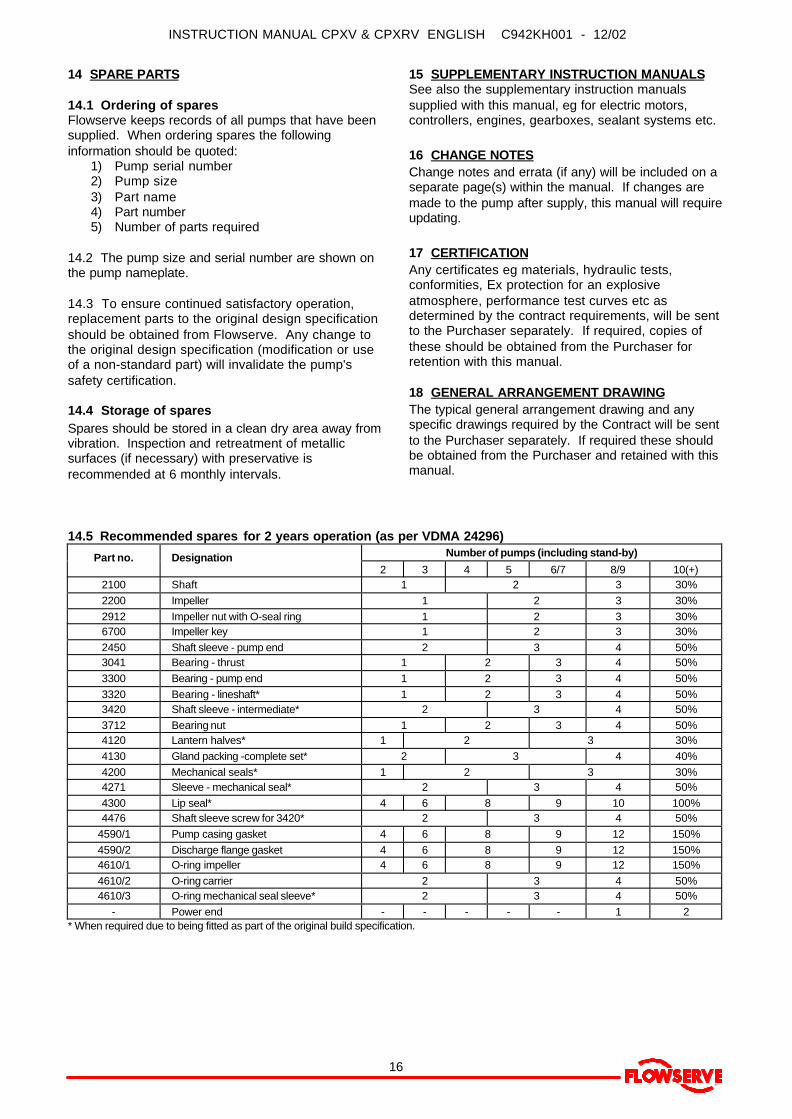
14.5 Recommended spares for 2 years operation (as per VDMA 24296)Number of pumps (including stand-by)Part no. Designation
2 3 4 5 6/7 8/9 10(+)2100 Shaft 1 2 3 30%2200 Impeller 1 2 3 30%2912 Impeller nut with O-seal ring 1 2 3 30%6700 Impeller key 1 2 3 30%2450 Shaft sleeve - pump end 2 3 4 50%3041 Bearing - thrust 1 2 3 4 50%3300 Bearing - pump end 1 2 3 4 50%3320 Bearing - lineshaft* 1 2 3 4 50%3420 Shaft sleeve - intermediate* 2 3 4 50%3712 Bearing nut 1 2 3 4 50%4120 Lantern halves* 1 2 3 30%4130 Gland packing -complete set* 2 3 4 40%4200 Mechanical seals* 1 2 3 30%4271 Sleeve - mechanical seal* 2 3 4 50%4300 Lip seal* 4 6 8 9 10 100%4476 Shaft sleeve screw for 3420* 2 3 4 50%
4590/1 Pump casing gasket 4 6 8 9 12 150%4590/2 Discharge flange gasket 4 6 8 9 12 150%4610/1 O-ring impeller 4 6 8 9 12 150%4610/2 O-ring carrier 2 3 4 50%4610/3 O-ring mechanical seal sleeve* 2 3 4 50%
- Power end - - - - - 1 2* When required due to being fitted as part of the original build specification.

INSTRUCTION MANUAL CPXV & CPXRV ENGLISH C942KH001 - 12/02
®
17
19 OPERATING DIFFICULTIESSYMPTOMS
PUMP OVERHEATS AND SEIZESBEARINGS HAVE SHORT LIFE ⇓⇓
PUMP VIBRATES OR IS NOISY ⇓⇓MECHANICAL SEAL HAS SHORT LIFE ⇓⇓
MECHANICAL SEAL LEAKS EXCESSIVELY ⇓⇓PUMP REQUIRES EXCESSIVE POWER ⇓⇓
PUMP LOSES PRIME AFTER STARTING ⇓⇓INSUFFICIENT PRESSURE DEVELOPED ⇓⇓
INSUFFICIENT CAPACITY DELIVERED ⇓⇓PUMP DOES NOT DELIVER LIQUID ⇓⇓
⇓⇓
SUCTION TROUBLESPump or suction pipe not completely filled with liquid. l l l lSuction lift too high. l l l lInsufficient margin between suction pressure and vapour pressure. l l l lExcessive amount of air or gas in liquid. l l lInlet of suction pipe insufficiently submerged. l l l l
SYSTEM TROUBLESSpeed too low. l l lSpeed too high. lTotal head of system higher than head of pump. l l lTotal head of system lower than pump design head. lSpecific gravity of liquid different from design. lViscosity of liquid differs from that for which designed. l l lOperation at very low capacity. l lOperation at high capacity. l l l
MECHANICAL TROUBLESMisalignment due to pipe strain. l l l l l lImproperly designed foundation. lShaft bent. l l l l lRotating part rubbing on stationary part internally. l l l lBearings worn l l l l lWearing ring surfaces worn. l l lImpeller damaged or eroded. l l lLeakage under sleeve due to joint failure. lShaft sleeve worn or scored or running off centre. l lMechanical seal improperly installed. l l lIncorrect type of mechanical seal for operating conditions. l l lShaft running off centre because of worn bearings or misalignment. l l l l lImpeller out of balance resulting in vibration. l l l l lAbrasive solids in liquid pumped. l l lInternal misalignment of parts preventing seal ring and seat from mating properly. l lMechanical seal was run dry. l lInternal misalignment due to improper repairs causing impeller to rub. l lExcessive thrust caused by a mechanical failure inside the pump. l l lExcessive grease in ball bearings. l lLack of lubrication for bearings. l lImproper installation of bearings (damage during assembly, incorrect assembly, wrong type ofbearing etc).
l l
Damaged bearings due to contamination. l l
MOTOR ELECTRICAL PROBLEMSWrong direction of rotation. l l l lMotor running on 2 phases only. l lMotor running too slow, check terminal box. l l l

INSTRUCTION MANUAL CPXV & CPXRV ENGLISH C942KH001 - 12/02
®
18
20 SECTIONAL ARRANGEMENT DRAWINGS AND PARTS LISTS
20.1 CPXV
8010
3160/1
2540
3240
7450
7000
9906/6
6742
3712/1
9906/3
9906/4
9906/2
3712/2
2100
3032
3853
9923/1
4610/2
9923/3
9951/1
3864
1341/2
3142
4476
1360
1341/1
2450
3840
3250
9905/2
9923/2
9906/5
3420
2500
3320
3245
4590/2
3300
9906/7
9923/4
2200
1111
9906/1
4610/1
4590/1
9923/3
6531
9905/1
Reference Name of part1111 Pump casing
1341/1 Lower support column1360 Discharge pipe2100 Shaft2200 Impeller2450 Shaft sleeve2540 Flinger (liquid)2912 Impeller nut3032 Double thrust bearing3142 Motor stool & soleplate3240 Bearing carrier3245 Bearing carrier (pump end)3300 Bearing bush
3712/1 Bearing nut3712/2 Bearing outer nut3840 Lubricating pipe3853 Grease nipple3864 Grease retainer rings
4590/1 Pump casing gasket4590/2 Discharge flange gasket4590/3 Impeller gasket4610/1 O-ring (impeller)4610/2 O-ring (bearing carrier)6710 Impeller key6742 Coupling key7000 Coupling7450 Coupling guard8010 Motor
9905/1 Capscrew (bearing retaining)9906/1 Screws (column/casing)9906/2 Screws (bearing carrier)9906/3 Screws (adjusting)9906/4 Screws (column/soleplate)9906/6 Screws (motor/stool)9906/7 Screws (strainer)9923/1 Nuts (locking)
Inter bearing parts (when required)1341/2 Upper support column2500 Shaft collar3320 Intermediate bearing bush3420 Intermediate bearing sleeve4476 Sleeve drive screw
9905/2 Capscrew (bearing retaining)9906/5 Bolts (column)9923/2 Nuts (column)
Optional item6531 Suction strainer

INSTRUCTION MANUAL CPXV & CPXRV ENGLISH C942KH001 - 12/02
®
19
20.2 CPXV optional features (CPXRV arrangement)
9906/2
8010
3160/1
2540
3240
3142
9906/4
3032
3712/2
2100
4476
1360
1341/1
3840
2450
3245
3300
2510
4590/2
9906/7
9923/4
2200
7450
7000
9906/6
6742
9906/3
3712/1
9923/1
3853
4610/2
9923/3
9951/1
3864
1341/2
3250
9905/2
9906/5
9923/2
3320
3420
2500
9905/1
9906/1
4590/3
4590/1
4610/1
1111
Enlarged view showing recessed impeller and spacer ring

INSTRUCTION MANUAL CPXV & CPXRV ENGLISH C942KH001 - 12/02
®
20
20.3 CPXV optional features (continued)
4223
6515
3854
6521
3855
4476/13420/1
3670/1
3320/1
3711
3670/2
9906/9
4476/2
3670/4
2500/1
3300/1
3670/3
3400/1
2500/2
Pair of 40° angular contact bearings, grease lubricated. (No sleeve fitted on shaft sizes 1 & 2).
Pair of 40° angular contact bearings, oil lubricated. (No sleeve fitted on shaft sizes 1 & 2).
Standard double row angular contact bearings, grease lubricated (shown with proprietary labyrinth seal fitted into bearing outer nut).
Reference Name of part2500/1 Shaft collar2500/2 Shaft collar3300/1 Bearing bush3320/1 Intermediate bearing bush3400/1 Bearing sleeve3420/1 Intermediate bearing sleeve3670/1 Bearing ring (inter-bush)3670/2 Bearing ring (inter-sleeve)3670/3 Bearing ring (bush)3670/4 Bearing ring (sleeve)4476/1 Sleeve drive screw4476/2 Sleeve drive screw6521 Plug
9906/9 Screw (bush retaining)
Special build parts, when required3711 Labyrinth disc3854 Breather3855 Constant level oiler4223 Pumping ring6515 Drain plug
CPXV special build parts shown• fluorosilicon greased thrust bearing with proprietary
labyrinth• silicon carbide long life bearings

INSTRUCTION MANUAL CPXV & CPXRV ENGLISH C942KH001 - 12/02
®
21
20.4 CPXV optional features (continued)
Carbon segmental bush
Proprietary labyrinth seal
Magnetic face seal
PTFE lip seal
Packed gland
CPXV sealing options shown• soleplate/vapour seal options (see 21.5 for
mechanical seal)

INSTRUCTION MANUAL CPXV & CPXRV ENGLISH C942KH001 - 12/02
®
22
20.5 CPXV optional features (continued)
7000/1
CB
9906/8
4200
3160/2
9951/2
9923/4
9951/3
A9923/3
(Half section) (Half section)
Reference Name of part3160/2 Spacer stool4200 Mechanical seal
7000/1 Coupling, spacer type9906/8 Screws (spacer/motor stool)9923/3 Nuts (seal cover)9923/4 Nuts (column/soleplate)9951/2 Studs (seal cover)9951/3 Studs (column/soleplate)
CPXV special build parts shown• spacer coupling• cartridge mechanical seal
A. proprietaryB. IDP unbalancedC. IDP balanced (when fitted)

INSTRUCTION MANUAL CPXV & CPXRV ENGLISH C942KH001 - 12/02
®
23
21 PARTS INTERCHANGEABILITY
CPXV pump size Bearing carrier Casing gasket Line bearing fluorosintLine bearing
silicon carbide40-25CPXV125 1 1 1 1
50-32CPXV125 1 1 1 1
65-40CPXV125 1 1 1 1
80-50CPXV125 1 1 1 1
100-80CPXV125 1 1 1 1
32-20CPXV160 1 2 1 1
40-25CPXV160 1 2 1 1
50-32CPXV160 1 2 1 1
65-40CPXV160 1 2 1 1
80-50CPXV160 1 2 1 1
100-65CPXV160 2 2 2 1
125-100CPXV160 2 2 2 1
32-20CPXV200 1 3 1 1
40-25CPXV200 1 3 1 1
50-32CPXV200 1 3 1 165-40CPXV200 1 3 1 1
80-50CPXV200 1 3 1 1
100-65CPXV200 2 3 2 1
125-100CPXV200 2 3 2 1
40-25CPXV250 2 4 2 1
50-32CPXV250 2 4 2 1
65-40CPXV250 2 4 2 1
80-50CPXV250 2 4 2 1
100-65CPXV250 2 4 2 1
125-100CPXV250 3 4 2 2
150-125CPXV250 3 4 2 2
200-150CPXV250 3 4 2 2
50-32CPXV315 2 5 2 1
65-40CPXV315 2 5 2 180-50CPXV315 2 5 2 1
100-65CPXV315 3 5 2 2
125-80CPXV315 3 5 2 2
150-125CPXV315 3 5 2 2
200-150CPXV315 4 5 3 2
100-65CPXV400 3 6 2 2
125-80CPXV400 3 5 2 2
150-125CPXV400 3 6 2 2
200-150CPXV400 4 6 3 2
250-200CPXV400 4 6 3 2
200-150CPXV500 4 7 3 2

INSTRUCTION MANUAL CPXV & CPXRV ENGLISH C942KH001 - 12/02
®
24
Europe, Middle East & AfricaFlowserve Limited (Pump Division)Harley House, 94 Hare LaneClaygate, Esher, Surrey KT10 0RBUnited Kingdom
Tel +44 (0)1372 463 700Fax +44 (0)1372 460 190
USA and CanadaFlowserve Corporation (Pump Division)Millennium Center, 222 Las Colinas Blvd.15th Floor, Irving, TX 75039-5421, USA
Tel +1 972 443 6500Toll free 800 728 PUMP (7867)Fax +1 972 443 6800
Latin AmericaFlowserve S.A. de C.V.Avenida Paseo de la Reforma #302nd Floor, Colonia Juarez CentroMexico, D.F.Z.C. 06040
Tel +52 5705 5526Fax +52 5705 1125
Asia PacificFlowserve Pte Ltd (Pump Division)200 Pandan Loop, #06-03/04Pantech 21, Singapore 128388
Tel +65 775 3003Fax +65 779 4607
Visit our web site at: www.flowserve.com
Your Flowserve factory contact:
Flowserve Pumps LimitedPO Box 17, NewarkNotts NG24 3ENUnited Kingdom
Telephone (24 hours) +44 (0)1636 494 600Sales & Admin Fax +44 (0)1636 705 991Repair & Service Fax +44 (0)1636 494 833E.mail [email protected]
Your local Flowserve representative:
To find your local Flowserve representative, pleaseuse the Sales Support Locator System found atwww.flowserve.com