invitation to computer science 6th edition chapter 4 the building blocks: binary numbers, boolean...
TRANSCRIPT
Invitation to Computer Science 6th Edition
Chapter 4
The Building Blocks: Binary Numbers, Boolean
Logic, and Gates

Invitation to Computer Science, 6th Edition 2
Objectives
In this chapter, you will learn about:
• The binary numbering system
• Boolean logic and gates
• Building computer circuits
• Control circuits

Invitation to Computer Science, 6th Edition 33
Introduction
• Computing agent– Abstract concept representing any object capable of
understanding and executing our instructions
• Fundamental building blocks of all computer systems – Binary representation– Boolean logic– Gates– Circuits

Invitation to Computer Science, 6th Edition 44
The Binary Numbering System
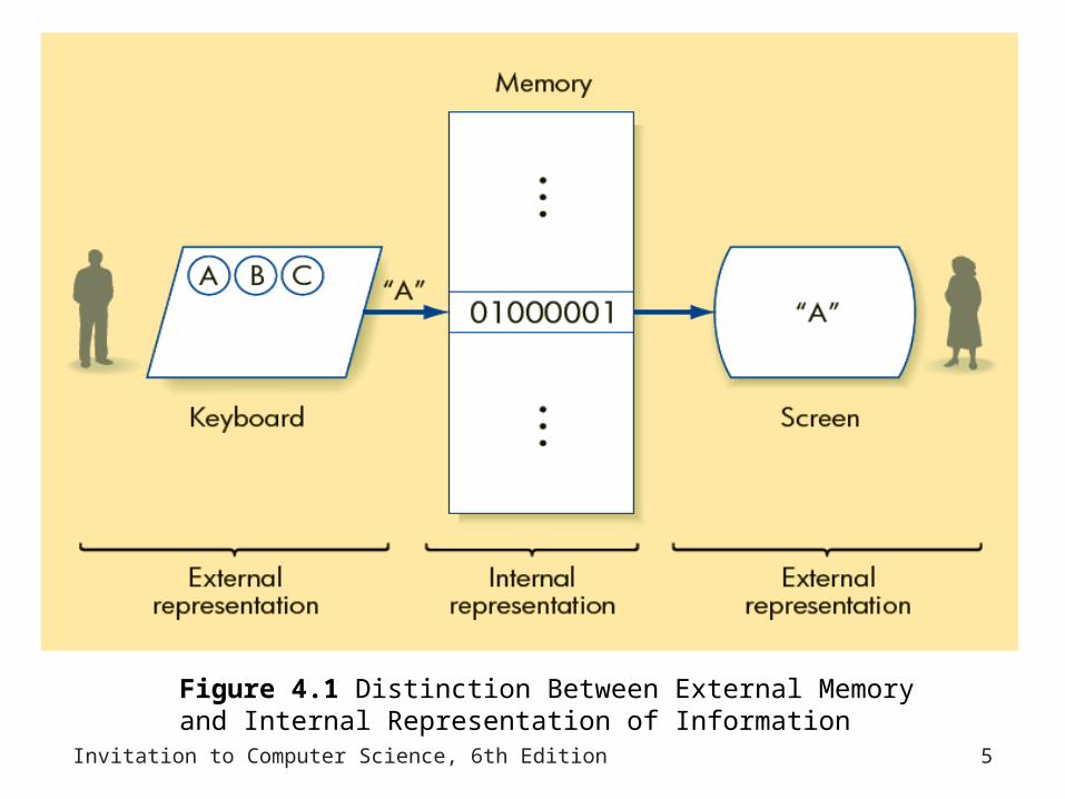
• Binary representation of numeric and textual information– Two types of information representation
• External representation
• Internal representation
– Binary is a base-2 positional numbering system
Invitation to Computer Science, 6th Edition 5
Figure 4.1 Distinction Between External Memory and Internal Representation of Information

Invitation to Computer Science, 6th Edition 6
Binary Representation of Numeric and Textual Information
• Binary numbering system (Computer)– Base-2– Built from ones and zeros– Each position is a power of 2– 1101 = 1 x 23 + 1 x 22 + 0 x 21 + 1 x 20
• Decimal numbering system (Daily Life)– Base-10– Each position is a power of 10– 3052 = 3 x 10³ + 0 x 102 + 5 x 101 + 2 x 100

Invitation to Computer Science, 6th Edition 7
Binary Representation of Numeric and Textual Information
• Binary-to-decimal algorithm– Whenever there is a 1 in a column, add the
positional value of that column to a running sum– Whenever there is a 0 in a column, add nothing– The final sum is the decimal value of this binary
number

Invitation to Computer Science, 6th Edition 8
Figure 4.2 Binary-to-Decimal Conversion Table

Invitation to Computer Science, 6th Edition 9
Binary Representation of Numeric and Textual Information (continued)
• To convert a decimal value into its binary equivalent– Use the decimal-to-binary algorithm
• Maximum number of binary digits that can be used to store an integer: 16, 32, or 64 bits
• Given k bits, the largest unsigned integer is 2k-1
• Arithmetic overflow– Operation that produces an unsigned value greater
than 65,535
Invitation to Computer Science, 6th Edition 10
Signed Numbers
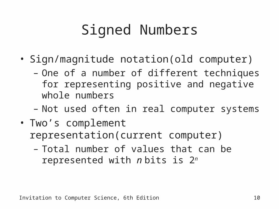
• Sign/magnitude notation(old computer)– One of a number of different techniques for
representing positive and negative whole numbers– Not used often in real computer systems
• Two’s complement representation(current computer)– Total number of values that can be represented with
n bits is 2n

Invitation to Computer Science, 6th Edition 11
Signed Numbers
• 1(sign bit) 110001 (total: 7 bits, computer A)– When it is a signed value, it is -49– When it is a unsigned value, it is 113
• 1(sign bit) 0110001 (total: 8 bits, computer B)– When it is a signed value, it is -49– When it is a unsigned value, it is 177
• You must tell the computer if it is signed or unsigned integer. The number of bit depends on computer (8bit, 16bit, 32bit, 64bit)

Invitation to Computer Science, 6th Edition 12
Two's complement notation
• Why we have this solution?– Because of two zeros problem in Sign/Magnitude
notation : 10000, 00000– if (a = b)– do operation 1– else– do operation 2

Invitation to Computer Science, Java Version, Third Edition 13
Two's complement notation
If A > 0 then do nothing else get complement value of each bit a <- a+1 Eg: -3 (3bit): 3 -> 011 -> 100 -> 101 -3 (4bit): 3 -> 0011 -> 1100 -> 1101 The number of bit depends on computer (8bit, 16bit, 32bit, 64bit)
Easier method: Get complement value of each bit until before right most 1 Eg: -3 (3bit): 3-> 011 -> 101 -3 (4bit) : 3 -> 0011 -> 1101
No substraction in two’s complement notation. Convert to complement value. Eg 5 – 3 = 5 + (-3)

Invitation to Computer Science, 6th Edition 14
Two's complement notation
• Bit pattern Decimal Value
• 001 +1
• 010 +2
• 011 +3
• 100 -4
• 101 -3
• 110 -2
• 111 -1

Invitation to Computer Science, 6th Edition 15
Compare value range
• Suppose we have k bit.• Sign/Magnitude notation: -(2k-1 – 1) to (2k-1 – 1)
– Eg. 3bit: -3 ~ +3
• Two’s complement notation:-(2k-1) to (2k-1 – 1) – Eg 3bit: -4 ~ +3
• Why different?– Eg. 3bit: -3 ~ +3
– Because Sign/Magnitude notation has two zeros while two’s complement notation has only one zero.
– Though two’s complement notation is difficult to human, it much clearer to computer.

Invitation to Computer Science, 6th Edition 16
Fractional Numbers
• Fractional numbers (12.34 and –0.001275)– Can be represented in binary by using signed-
integer techniques
• Scientific notation– ±M x B±E
– M is the mantissa, B is the exponent base (usually 2), and E is the exponent
• Normalize the number– First significant digit is immediately to the right of the
binary point
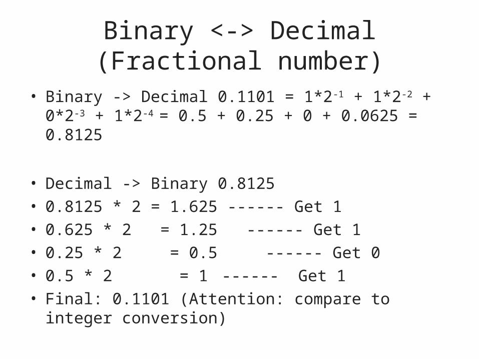
Binary <-> Decimal (Fractional number)
• Binary -> Decimal 0.1101 = 1*2-1 + 1*2-2 + 0*2-3 + 1*2-4 = 0.5 + 0.25 + 0 + 0.0625 = 0.8125
• Decimal -> Binary 0.8125
• 0.8125 * 2 = 1.625 ------ Get 1
• 0.625 * 2 = 1.25 ------ Get 1
• 0.25 * 2 = 0.5 ------ Get 0
• 0.5 * 2 = 1 ------ Get 1
• Final: 0.1101 (Attention: compare to integer conversion)

Invitation to Computer Science, 6th Edition 18
Textual Information
• Code mapping– Assigning each printable letter or symbol in our
alphabet a unique number
• ASCII– International standard for representing textual
information in the majority of computers– Uses 8 bits to represent each character (256characters)
• UNICODE – Uses a 16-bit representation for characters rather
than the 8-bit format of ASCII(655,36characters)

Invitation to Computer Science, 6th Edition 19
Figure 4.3 ASCII Conversion Table

Invitation to Computer Science, 6th Edition 20
Binary Representation of Sound and Images
• Digital representation– Values for a given object are drawn from a finite set
• Analog representation– Objects can take on any value
• Figure 4.4– Amplitude of the wave: measure of its loudness– Period of the wave (T): time it takes for the wave to
make one complete cycle– Frequency f: total number of cycles per unit time

Invitation to Computer Science, 6th Edition 21
Figure 4.4 Example of Sound Represented as a Waveform

Invitation to Computer Science, 6th Edition 22
Binary Representation of Sound and Images (continued)
• Sampling rate– Measures how many times per second we sample
the amplitude of the sound wave• Bit depth
– Number of bits used to encode each sample• MP3
– Most popular and widely used digital audio format• Scanning
– Measuring the intensity values of distinct points located at regular intervals across the image’s surface
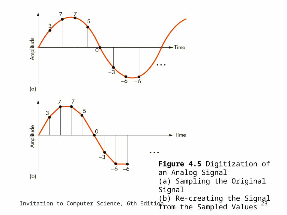
Invitation to Computer Science, 6th Edition 23
Figure 4.5 Digitization of an Analog Signal(a) Sampling the Original Signal(b) Re-creating the Signal from the Sampled Values

Binary Representation of Sound and Images (continued)
• Raster graphics– Each pixel is encoded as an unsigned binary value
representing its gray scale intensity
• RGB encoding scheme– Most common format for storing color images
• True Color– 24-bit color-encoding scheme
• Data compression algorithms – Attempt to represent information in ways that preserve
accuracy while using significantly less space
Invitation to Computer Science, 6th Edition 24

Invitation to Computer Science, Java Version, Third Edition 25
Data Compression
• Why we need data compression?– Because the original data need too much space.– Eg. 3,000,000 pixels/photograph * 24 bits/pixel = 72million bits.
•Simple compression method – “run – length encoding” for image compression
– Replaces a sequence of identical values v1, v2, . . ., vn by a pair of values (v, n)
– Eg. (255 255 255), (255, 0, 0), (255, 255, 255), (255, 0, 0), (255, 255, 255) → (255, 4), (0, 2), (255, 4), (0, 2), (255, 3)
Invitation to Computer Science, Java Version, Third Edition 26
Data Compression
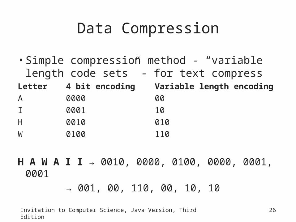
• Simple compression method - “variable length code sets” - for text compress
Letter 4 bit encoding Variable length encoding
A 0000 00
I 0001 10
H 0010 010
W 0100 110
H A W A I I → 0010, 0000, 0100, 0000, 0001, 0001
→ 001, 00, 110, 00, 10, 10

Invitation to Computer Science, 6th Edition 27
Figure 4.8 Using Variable Length Code Sets(a) Fixed Length(b) Variable Length

Invitation to Computer Science, Java Version, Third Edition 28
Data Compression
• Compression rate = size of the uncompressed data / size of the compressed data
– Measures how much compression schemes reduce storage requirements of data
Invitation to Computer Science, 6th Edition 29
Binary Representation of Sound and Images (continued)
• Lossless compression schemes– No information is lost in the compression– It is possible to exactly reproduce the original data
• Lossy compression schemes – Do not guarantee that all of the information in the
original data can be fully and completely recreated

Invitation to Computer Science, 6th Edition 30
The Reliability of Binary Representation
• Computers use binary representation for reasons of reliability
• Building a base-10 “decimal computer”– Requires finding a device with 10 distinct and stable
energy states that can be used to represent the 10 unique digits (0, 1, . . . , 9) of the decimal system
• Bistable environment– Only two (rather than 10) stable states separated by
a huge energy barrier
Invitation to Computer Science, 6th Edition 31
Binary Storage Devices
• Magnetic cores – Used to construct computer memories
• Core– Small, magnetizable, iron oxide-coated “doughnut,”
about 1/50 of an inch in inner diameter, with wires strung through its center hole

Invitation to Computer Science, 6th Edition 32
Figure 4.9 Using Magnetic Cores to Represent Binary Values

Invitation to Computer Science, 6th Edition 33
Binary Storage Devices (continued)
• Transistor – Solid-state device that has no mechanical or moving
parts– Constructed from semiconductors– Can be printed photographically on a wafer of silicon
to produce a device known as an integrated circuit
• Circuit board– Interconnects all the different chips needed to run a
computer system

Invitation to Computer Science, 6th Edition 34
Figure 4.10 Relationships Among Transistors, Chips, and Circuit Boards

Invitation to Computer Science, 6th Edition 35
Binary Storage Devices (continued)
• Mask – Can be used to produce a virtually unlimited number
of copies of a chip
• Figure 4.11– Control (base): used to open or close the switch
inside the transistor– ON state: current coming from the In line
(Collector) can flow directly to the Out line (Emitter), and the associated voltage can be detected by a measuring device

Invitation to Computer Science, 6th Edition 36
Figure 4.11 Simplified Model of a Transistor

Invitation to Computer Science, 6th Edition 37
Boolean Logic
• Boolean logic– Construction of computer circuits is based on this– Boolean expression
• Constructed by combining together Boolean operations
• Example: (a AND b) OR ((NOT b) AND (NOT a))
– Truth table• capture the output/value of a Boolean expression
• A column for each input plus the output
• A row for each combination of input values

Invitation to Computer Science, 6th Edition 38
Figure 4.12 Truth Table for the AND Operation

Invitation to Computer Science, 6th Edition 39
Boolean Logic (continued)
• Boolean operations– AND, OR, NOT
• Binary operators– Require two operands
• Unary operator– Requires only one operand
• NOT operation – Reverses, or complements, the value of a Boolean
expression

Invitation to Computer Science, 6th Edition 40
Figure 4.13 Truth Table for the OR Operation

Invitation to Computer Science, 6th Edition 41
Figure 4.14 Truth Table for the NOT Operation

Gates• Gate
– Hardware devices built from transistors to mimic Boolean logic
• AND gate– Two input lines, one output line– Outputs a 1 when both inputs are 1
Invitation to Computer Science, 6th Edition 42

Gates(continued)• OR gate
– Two input lines, one output line– Outputs a 1 when either input is 1
• NOT gate– One input line, one output line– Outputs a 1 when input is 0 and vice versa
Invitation to Computer Science, 6th Edition 43

Invitation to Computer Science, 6th Edition 44
Figure 4.15 The Three Basic Gates and Their Symbols

Gates(continued)• Abstraction in hardware design
– Map hardware devices to Boolean logic– Design more complex devices in terms of logic, not
electronics– Conversion from logic to hardware design can be
automated
Invitation to Computer Science, 6th Edition 45

Invitation to Computer Science, 6th Edition 46
Building Computer Circuits
• Introduction– Circuit: collection of logic gates that transforms a
set of binary inputs into a set of binary outputs
• Every Boolean expression: – Can be represented pictorially as a circuit diagram
• Every output value in a circuit diagram: – Can be written as a Boolean expression
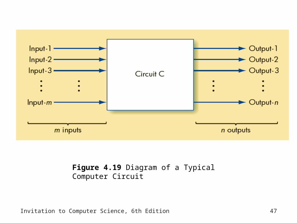
Invitation to Computer Science, 6th Edition 47
Figure 4.19 Diagram of a Typical Computer Circuit

Invitation to Computer Science, 6th Edition 48
A Circuit Construction Algorithm
• Step 1: Truth Table Construction– Determine how the circuit should behave under all
possible circumstances– If a circuit has N input lines and if each input line can
be either a 0 or a 1, then:• There are 2N combinations of input values, and the
truth table has 2N rows
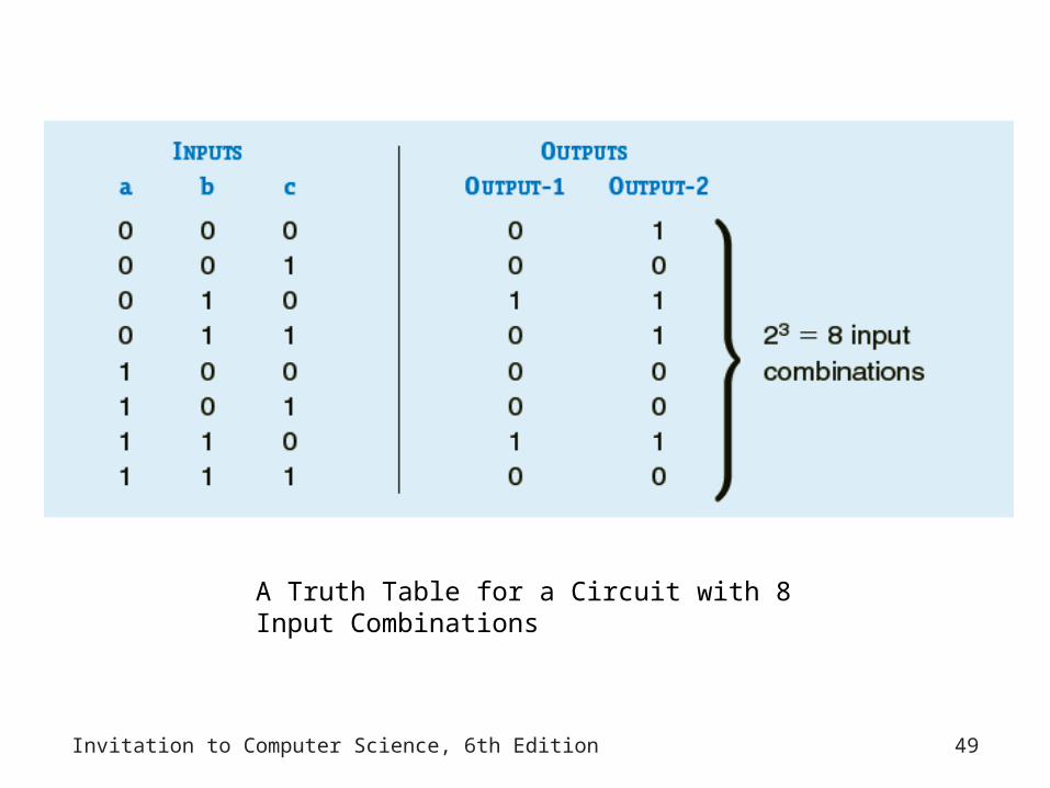
Invitation to Computer Science, 6th Edition 49
A Truth Table for a Circuit with 8 Input Combinations

Invitation to Computer Science, 6th Edition 50
A Circuit Construction Algorithm (continued)
• Step 2: Subexpression Construction Using AND and NOT Gates– Choose any one output column of the truth table built
in step 1, and scan down that column– Every place that you find a 1 in that output column,
you build a Boolean subexpression that produces the value 1 for exactly that combination of input values and no other

Invitation to Computer Science, 6th Edition 51
Output Column Labeled Output-1 from the Previous Truth Table

Invitation to Computer Science, 6th Edition 52
Taking Snapshots
• Step 3: Subexpression Combination Using OR Gates– Take each of the subexpressions produced in step 2
and combine them, two at a time, using OR gates
• Step 4: Circuit Diagram Production– Construct the final circuit diagram
• Algorithms for circuit optimization– Reduce the number of gates needed to implement a
circuit
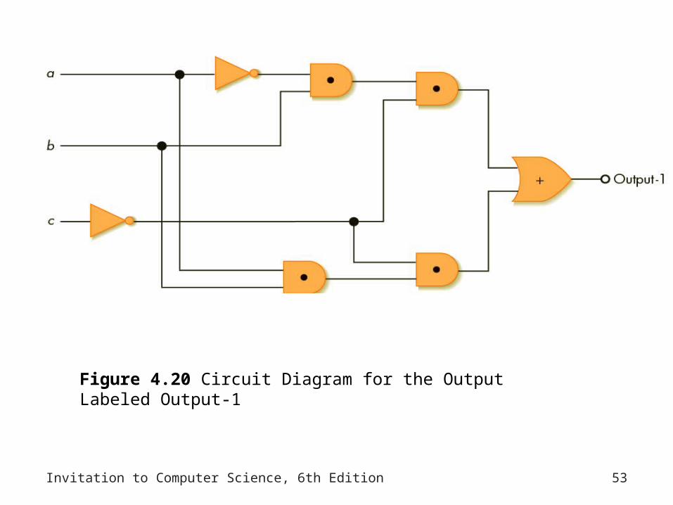
Invitation to Computer Science, 6th Edition 53
Figure 4.20 Circuit Diagram for the Output Labeled Output-1

Invitation to Computer Science, 6th Edition 54
Figure 4.21 The Sum-of-Products Circuit Construction Algorithm

Invitation to Computer Science, 6th Edition 55
Examples of Circuit Design and Construction
• A Compare-For-Equality Circuit– Tests two unsigned binary numbers for exact
equality– Produces the value 1 (true) if the two numbers are
equal and the value 0 ( false) if they are not

Invitation to Computer Science, 6th Edition 56
Figure 4.22 One-Bit Compare for Equality Circuit

Invitation to Computer Science, 6th Edition 57
Figure 4.23 N-Bit Compare for Equality Circuit

Invitation to Computer Science, 6th Edition 58
An Addition Circuit
• Full adder– Performs binary addition on two unsigned N-bit
integers
• Figure 4.27– Shows the complete full adder circuit called ADD
• Addition circuits – Found in every computer, workstation, and handheld
calculator in the marketplace

Invitation to Computer Science, 6th Edition 59
Figure 4.24 The 1-ADD Circuit and Truth Table
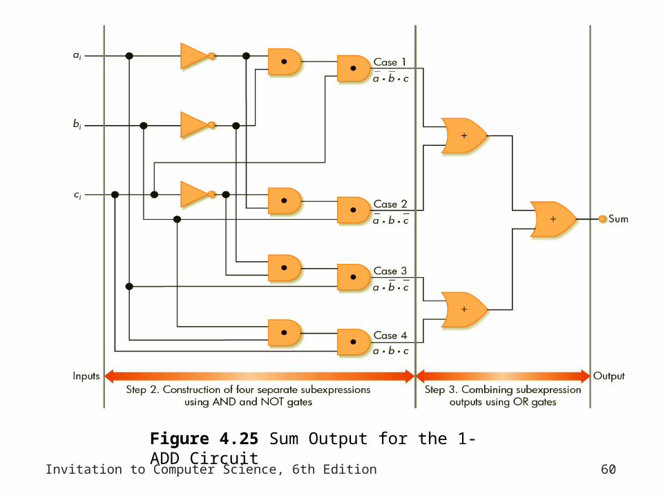
Invitation to Computer Science, 6th Edition 60
Figure 4.25 Sum Output for the 1-ADD Circuit

Invitation to Computer Science, 6th Edition 61
Figure 4.26 Complete 1-ADD Circuit for 1-Bit Binary Addition

Invitation to Computer Science, 6th Edition 62
Figure 4.27 The Complete Full Adder ADD Circuit

Invitation to Computer Science, 6th Edition 63
Control Circuits
• Used to: – Determine the order in which operations are carried
out – Select the correct data values to be processed
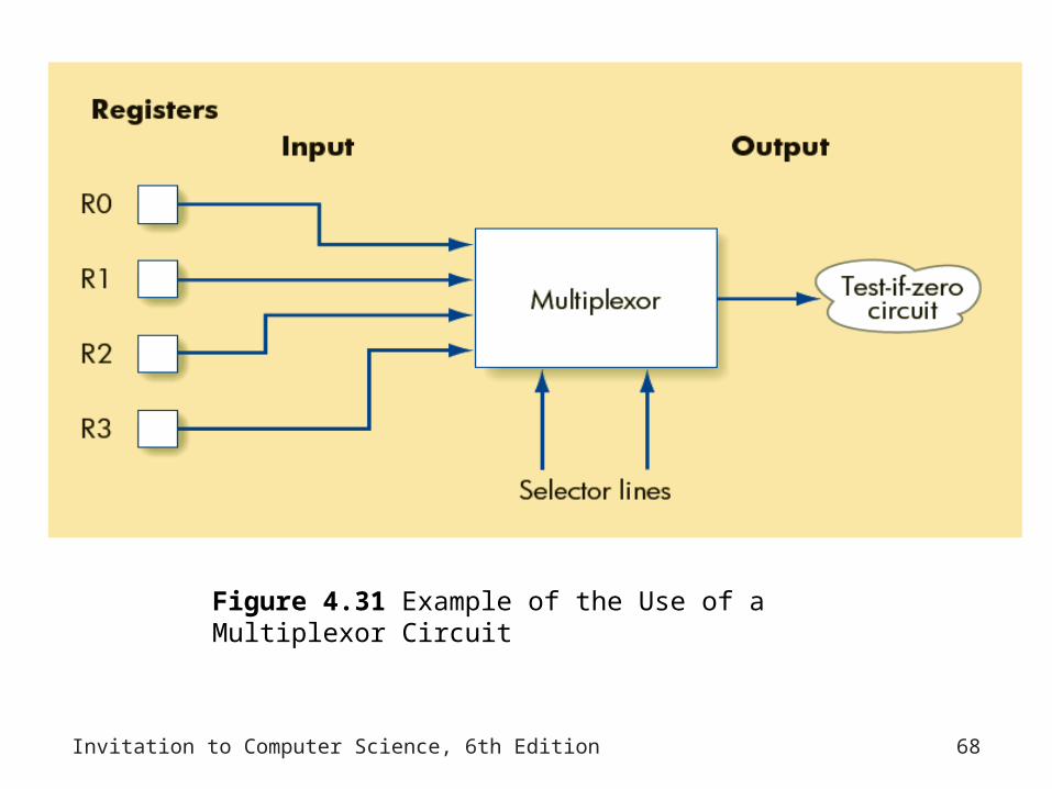
• Multiplexor– Circuit that has 2N input lines and 1 output line– Function: to select exactly one of its 2N input lines
and copy the binary value on that input line onto its single output line

Invitation to Computer Science, 6th Edition 64
Figure 4.28 A Two-Input Multiplexor Circuit
Invitation to Computer Science, 6th Edition 65
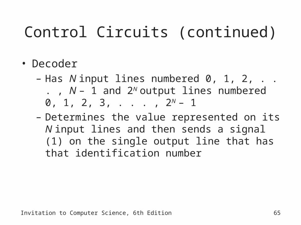
Control Circuits (continued)
• Decoder – Has N input lines numbered 0, 1, 2, . . . , N – 1 and
2N output lines numbered 0, 1, 2, 3, . . . , 2N – 1– Determines the value represented on its N input
lines and then sends a signal (1) on the single output line that has that identification number

Invitation to Computer Science, 6th Edition 66
Figure 4.29 A 2-to-4 Decoder Circuit

Invitation to Computer Science, 6th Edition 67
Figure 4.30 Example of the Use of a Decoder Circuit
Invitation to Computer Science, 6th Edition 68
Figure 4.31 Example of the Use of a Multiplexor Circuit

Invitation to Computer Science, 6th Edition 69
Summary
• Digital computers– Use binary representations of data: numbers, text,
multimedia
• Binary values – Create a bistable environment, making computers reliable
• Boolean logic – Maps easily onto electronic hardware
Invitation to Computer Science, 6th Edition 70
Summary (continued)
• Circuits – Constructed using Boolean expressions as an abstraction
• Computational and control circuits – Can be built from Boolean gates