investigations of earthquake source processes based … of earthquake source processes based on...
TRANSCRIPT

Investigations of Earthquake Source Processes Based onFault Models with Variable Friction Rheology
Thesis by
Yoshihiro Kaneko
In Partial Fulfillment of the Requirements
for the Degree of
Doctor of Philosophy
California Institute of Technology
Pasadena, California
2009
(Defended January 30, 2009)

ii
c© 2009
Yoshihiro Kaneko
All Rights Reserved
iii
Acknowledgements
First and foremost, I would like to express my sincere gratitude to my advisor Nadia La-
pusta, for all her support, patience, and guidance during the course of my graduate study.
Nadia is always willing to spend hours with me on discussing my research, and has always
taken extremely good care of me and other students. I also deeply appreciate her support
while allowing me to pursue my ideas in the middle of my PhD.
I would like to thank all other members of my committee, Jean-Philippe Avouac, Pablo
Ampuero, Tom Heaton, and Rob Clayton for reviewing my thesis and providing valuable
suggestions and criticism. I am especially grateful to Jean-Philippe and Pablo for our re-
search collaboration that resulted in parts of this thesis. The research with Jean-Philippe
originated from his well-taught reading course (Ge 277) that motivated me to explain ob-
servations of seismic and aseismic slip. I have greatly benefited from discussions about
earthquake physics with Tom Heaton. Rob Clayton has been a very good academic advi-
sor.
Discussions with and lectures of Nadia Lapusta, Hiroo Kanamori, Jeroen Tromp, Don
Helmberger, Mark Simons, Rob Clayton, and Mike Gurnis have taught me a lot both about
scientific subjects and about ways to investigate them. I thank them for sharing their knowl-
edge and insight with me.
My sincere appreciation extends to my current and former colleagues. It has been a

iv
pleasure to discuss research with Yi Liu, Carl Tape, Elisabeth Nadin, Ozgun Konca, Eun-
Seo Choi, Daoyuan Sun, Ravi Kanda, Qinya Liu, Xiao Lu, Ting Chen, and Hiro Noda.
Frequent discussions with Yi Liu helped me to gain analytical insights for my complicated
numerical results. My PhD study would not have been smooth and fun without the friend-
ship of Carl and Elisabeth.
My understanding of earthquake source physics was enhanced by discussions with and
suggestions from researchers outside of Caltech, among them Allan Rubin, Yehuda Ben-
Zion, Paul Segall, Ralph Archuleta, Terry Tullis, Joan Gomberg, Jim Rice, and Eric Dun-
ham. I am grateful to all of them. I thank Yue Tian and Allan Rubin for giving me the
permission to use their figures in this thesis and for providing me with digital copies of
them.
I thank my parents in Japan for their understanding and support throughout my under-
graduate and graduate studies in the United States. At last, I want to express my big thanks
to my wife, Misaki, for her love, friendship, and support that made this work possible and
enjoyable.

v
Abstract
Ample experimental and observational evidence suggests that friction properties on natural
faults vary spatially. In the lab, rock friction depends on temperature and confining pressure
and it can be either velocity weakening or velocity strengthening, leading to either unstable
or stable slip. Such variations in friction rheology can explain patterns of seismic and
aseismic fault slip inferred from field observations.
This thesis studies earthquake source processes using models with relatively simple but
conceptually important patterns of velocity-weakening and velocity-strengthening friction
that can arise on natural faults. Based on numerical and analytical modeling, we explore the
consequences of such patterns for earthquake sequences, interseismic coupling, earthquake
nucleation processes, aftershock occurrence, peak ground motion in the vicinity of active
faults, and seismic slip budget at shallow depths. The velocity-dependence of friction is
embedded into the framework of logarithmic rate and state friction laws.
In addition to using existing boundary integral methods, which are accurate and effi-
cient in simulating slip on planar faults embedded in homogeneous elastic media, the thesis
develops spectral element methods to consider single dynamic ruptures and long-term his-
tories of seismic and aseismic slip in models with layered bulk properties.
The results of this thesis help to understand a number of observed fault slip phenom-
ena, such as variability in earthquake patterns and its relation to interseismic coupling,

vi
seismic quiescence following decay of aftershocks at inferred rheological transitions, in-
stances of poor correlation between static stress changes and aftershock occurrence, the
lack of universally observed supershear rupture near the free surface, and coseismic slip
deficit of large strike-slip earthquakes at shallow depths. The models, approaches, and nu-
merical methods developed in the thesis motivate and enable consideration of many other
earthquake source problems, such as the combined effect of two or more triggering mech-
anisms on aftershock rates, inferring friction properties on natural faults based on seismic
and geodetic measurements, seismic hazard assessment based on observed interseismic
coupling, and the effect of heterogeneous and/or nonelastic bulk properties on earthquake
sequences.

vii
Contents
Acknowledgements iii
Abstract v
1 Introduction 1
1.1 Observational and experimental evidence for systematic variations in fric-
tion properties on natural faults . . . . . . . . . . . . . . . . . . . . . . . .2
1.2 Understanding patterns and interactions of seismic and aseismic fault slip .8
1.3 Modeling earthquake nucleation and aftershock occurrence . . . . . . . . .11
1.4 Developing a spectral element method (SEM) for simulations of fault slip:
Effect of velocity-strengthening fault friction at shallow depths on dynamic
rupture . . . . . . . . . . . . . . . . . . . . . . . . . . . . . . . . . . . . .16
2 Influence of Variations in Fault Friction Rheology on Earthquake Rupture
Patterns and Interseismic Coupling 21
2.1 Numerical model of earthquake cycles with heterogeneous interseismic
coupling . . . . . . . . . . . . . . . . . . . . . . . . . . . . . . . . . . . .22
2.2 Earthquake sequence in presence of a velocity-
strengthening (VS) patch . . . . . . . . . . . . . . . . . . . . . . . . . . .23

viii
2.3 Characteristics of individual earthquakes . . . . . . . . . . . . . . . . . . .26
2.4 Quantifying the influence of a velocity-strengthening (VS) patch on inter-
seismic coupling and the rupture pattern . . . . . . . . . . . . . . . . . . .27
2.5 Conclusions . . . . . . . . . . . . . . . . . . . . . . . . . . . . . . . . . .32
2.6 Appendix: Description of the fault model and parameters . . . . . . . . . .34
2.7 Appendix: Criteria for spatial discretization and time-stepping parameters .36
2.8 Appendix: Definition of interseismic coupling (ISC) . . . . . . . . . . . .37
2.9 Appendix: Derivation of the non-dimensional model parameterB . . . . . 38
2.10 Appendix: Relation among the non-dimensional parameterB, the percent-
age of two-segment rupturesP, and interseismic coupling (ISC) over a
range of parameters . . . . . . . . . . . . . . . . . . . . . . . . . . . . . .42
3 Variability of Earthquake Nucleation in Continuum Models of Rate and State
Faults 47
3.1 Previous theoretical studies of earthquake nucleation . . . . . . . . . . . .47
3.2 2D continuum models of earthquake nucleation . . . . . . . . . . . . . . .49
3.2.1 Model with a weaker patch . . . . . . . . . . . . . . . . . . . . . .51
3.2.2 Model with rheological transition . . . . . . . . . . . . . . . . . .53
3.3 Simulated nucleation processes . . . . . . . . . . . . . . . . . . . . . . . .55
3.3.1 Nucleation processes due to weaker patches and importance of nor-
mal stress heterogeneity . . . . . . . . . . . . . . . . . . . . . . .55
3.3.2 Nucleation processes due to rheological transitions . . . . . . . . .59
3.3.3 Different time evolution of nucleation in the two models . . . . . .61

ix
3.4 Dependence of nucleation processes and sizes on loading history . . . . . .63
3.5 Conclusions . . . . . . . . . . . . . . . . . . . . . . . . . . . . . . . . . .66
3.6 Appendix: Elastodynamic equations and numerical parameters . . . . . . .67
4 Aftershock Rates Due to Static Triggering in Continuum Models of Rate and
State Faults 69
4.1 Comparing nucleation processes by their response to static stress changes
and resulting aftershock rates . . . . . . . . . . . . . . . . . . . . . . . . .70
4.1.1 Procedure for determining aftershock rates . . . . . . . . . . . . .70
4.1.2 Aftershock rates based on nucleation processes at weaker patches:
Overall similarity to spring-slider models, effects of heterogeneous
normal stress . . . . . . . . . . . . . . . . . . . . . . . . . . . . .73
4.1.3 Aftershock rates based on nucleation processes at rheological tran-
sitions: Aftershock peaks and seismic quiescence . . . . . . . . . .76
4.1.4 Dependence of aftershock rates on constitutive parametersb andL . 82
4.2 Aftershock rates due to nonuniform stress changes in the model with rheo-
logical transition . . . . . . . . . . . . . . . . . . . . . . . . . . . . . . .83
4.3 The link between aftershock rates and slip-velocity history of unperturbed
nucleation processes . . . . . . . . . . . . . . . . . . . . . . . . . . . . .88
4.4 The relation between aftershock rates and the validity of the state-evolution
assumption . . . . . . . . . . . . . . . . . . . . . . . . . . . . . . . . . .91
4.4.1 Model with a weaker patch . . . . . . . . . . . . . . . . . . . . . .91
4.4.2 Model with rheological transition . . . . . . . . . . . . . . . . . .95

x
4.5 Conclusions . . . . . . . . . . . . . . . . . . . . . . . . . . . . . . . . . .95
4.6 Appendix: The model of aftershocks inDieterich[1994] . . . . . . . . . .100
4.7 Appendix: Aftershock rate calculations . . . . . . . . . . . . . . . . . . .104
4.7.1 For monotonic responsef(T) . . . . . . . . . . . . . . . . . . . . .104
4.7.2 For nonmonotonic responsef(T) . . . . . . . . . . . . . . . . . . .105
4.8 Appendix: Aftershock rates for simplified scenarios . . . . . . . . . . . . .106
4.8.1 Scenario 1: Nucleation zones withV θ/L¿ 1 before and after the
perturbation . . . . . . . . . . . . . . . . . . . . . . . . . . . . . .106
4.8.2 Scenario 2: Nucleation zones withV θ/L¿ 1 before the perturba-
tion butV θ/LÀ 1 after the perturbation . . . . . . . . . . . . . .108
4.8.3 Scenario 3: Nucleation zones close to failure withV θ/L ∼ 1 be-
fore the perturbation andV θ/LÀ 1 after the perturbation . . . . .109
4.8.3.1 Approach I . . . . . . . . . . . . . . . . . . . . . . . . .110
4.8.3.2 Approach II . . . . . . . . . . . . . . . . . . . . . . . .111
5 Spectral Element Modeling of Spontaneous Earthquake Rupture on Rate and
State Faults: Effect of Velocity-Strengthening Fault Friction at Shallow Depths
on Dynamic Rupture 113
5.1 Spectral element method (SEM) for simulations of dynamic ruptures . . . .114
5.2 A SEM algorithm for simulations of dynamic rupture on rate and state (RS)
faults . . . . . . . . . . . . . . . . . . . . . . . . . . . . . . . . . . . . .115
5.2.1 Discretized elastodynamic relations . . . . . . . . . . . . . . . . .115
5.2.2 Rate and state (RS) friction laws . . . . . . . . . . . . . . . . . . .118

xi
5.2.3 Updating scheme: advancing one evolution time step . . . . . . . .120
5.3 Comparison of numerical results obtained with 2D SEM and 2D BIM . . .123
5.3.1 2D antiplane problem and comparison criteria . . . . . . . . . . . .123
5.3.2 Convergence of SEM and BIM solutions with grid reduction . . . .127
5.3.3 Evaluation of state-variable updating schemes . . . . . . . . . . . .129
5.3.4 Comparison of simulations with linear slip-weakening (LSW) and
rate and state (RS) friction . . . . . . . . . . . . . . . . . . . . . .130
5.3.5 Simulations with the slip law of state-variable evolution . . . . . .134
5.4 Effect of velocity-strengthening fault friction at shallow depths on dynamic
rupture . . . . . . . . . . . . . . . . . . . . . . . . . . . . . . . . . . . . .136
5.4.1 Suppression of supershear rupture near the free surface . . . . . . .138
5.4.2 Smaller final slip throughout the fault . . . . . . . . . . . . . . . .141
5.4.3 Faster decrease of slip velocity behind the rupture front: implica-
tions for the rise time . . . . . . . . . . . . . . . . . . . . . . . . .143
5.5 Effect of velocity-strengthening friction at shallow depths on ground-motion
amplification due to a layered bulk structure . . . . . . . . . . . . . . . . .145
5.6 Conclusions . . . . . . . . . . . . . . . . . . . . . . . . . . . . . . . . . .150
5.7 Fault boundary matrix . . . . . . . . . . . . . . . . . . . . . . . . . . . . .151
5.8 Appendix: Rupture initiation procedure . . . . . . . . . . . . . . . . . . .152
6 Spectral Element Modeling of Long-term Slip Histories Punctuated by Dy-
namic Ruptures on Rate and State Faults 154

xii
6.1 A quasi-static SEM algorithm for simulations of long-term deformation
histories . . . . . . . . . . . . . . . . . . . . . . . . . . . . . . . . . . . .155
6.1.1 Discretized elastodynamic relations . . . . . . . . . . . . . . . . .155
6.1.2 Updating scheme: advancing one evolution time step during quasi-
static periods . . . . . . . . . . . . . . . . . . . . . . . . . . . . .158
6.2 Implementation example . . . . . . . . . . . . . . . . . . . . . . . . . . .161
6.2.1 Formulation of a 2D model . . . . . . . . . . . . . . . . . . . . . .161
6.2.2 Comparison of simulation results obtained with 2D SEM and 2D
BIM . . . . . . . . . . . . . . . . . . . . . . . . . . . . . . . . . .165
6.3 Effect of variable bulk properties on earthquake cycles: Can vertically strat-
ified bulk structure cause shallow coseismic slip deficit? . . . . . . . . . . .168
6.4 Conclusions . . . . . . . . . . . . . . . . . . . . . . . . . . . . . . . . . .175
6.5 Appendix: Variable evolution time step in 2D antiplane problems . . . . . .176

xiii
List of Figures
1.1 The pattern of locking of the plate interface along the subduction zone off-
shore Sumatra . . . . . . . . . . . . . . . . . . . . . . . . . . . . . . . . . .5
2.1 Schematic illustration for spatial variations of interseismic coupling (ISC)
on a plate interface along a generic subduction zone . . . . . . . . . . . . . .22
2.2 An example of the simulated long-term fault behavior . . . . . . . . . . . . .24
2.3 Characteristics of simulated earthquakes and postseismic slip . . . . . . . . .28
2.4 Phase diagrams that illustrate the effect of the central velocity-strengthening
patch on the long-term behavior of the model . . . . . . . . . . . . . . . . .30
2.5 Examples of simulated long-term fault behavior . . . . . . . . . . . . . . . .31
2.6 Illustration of interseismic periods in our simulations . . . . . . . . . . . . .38
2.7 Phase diagrams for models with different parameters . . . . . . . . . . . . .44
2.8 Relation between the non-dimensional parameterB and the percentage of
two-segment rupturesP (panels a, b), and simulated ISC (panels c, d) over a
range of parameters . . . . . . . . . . . . . . . . . . . . . . . . . . . . . . .46
3.1 3D schematics of a planar fault in an elastic medium and simplified 2D con-
tinuum models . . . . . . . . . . . . . . . . . . . . . . . . . . . . . . . . .50

xiv
3.2 Distributions of effective normal stressσ and initial shear stressτ o in the two
models . . . . . . . . . . . . . . . . . . . . . . . . . . . . . . . . . . . . .52
3.3 Examples of earthquake sequences simulated in the model with a weaker
patch and in the model with rheological transition . . . . . . . . . . . . . . .56
3.4 Nucleation processes at weaker patches and rheological transitions . . . . . .58
3.5 Slip-velocity evolution during one earthquake cycle for representative points
inside nucleation zones . . . . . . . . . . . . . . . . . . . . . . . . . . . . .61
3.6 Dependence of nucleation processes on loading history . . . . . . . . . . . .64
4.1 A cartoon illustrating a population of nucleation sites just before a stress
perturbation due to a mainshock . . . . . . . . . . . . . . . . . . . . . . . .71
4.2 Response to static stress steps and the resulting aftershock rates for Cases
1-3 of nucleation at a weaker patch . . . . . . . . . . . . . . . . . . . . . . .75
4.3 Response to static stress steps and the resulting aftershock rates for Cases 4
and 5 of nucleation at rheological transitions . . . . . . . . . . . . . . . . .77
4.4 Response to static stress steps in the model with rheological transition (Case 4)78
4.5 Model for estimating aftershock rates due to a population of nucleation sites
located along a segment of rheological transition perturbed by a mainshock
asperity . . . . . . . . . . . . . . . . . . . . . . . . . . . . . . . . . . . . .85
4.6 Aftershock rates computed for the nonuniform static stress change and a
population of nucleation sites located along the rheological transition . . . .86
4.7 Comparison of the aftershock rates computed using simulations with stress
perturbations and the semi-analytical estimate based on equation . . . . . . .90
xv
4.8 Aftershock rates for the analytical solution ofDieterich[1994] . . . . . . . .102
4.9 Schematics showing how the time to instability for each nucleation site in
the population changes due to a stress step for a monotonic functionf(T ) . . 103
4.10 An example of a non-monotonicf(T ) . . . . . . . . . . . . . . . . . . . . .107
5.1 The fault divided into two non-overlapping surfaces . . . . . . . . . . . . . .117
5.2 A cartoon illustrating the antiplane test problem for 2D SEM and 2D BIM . .124
5.3 Initial stress distribution and The effective slip dependence of rate and state
(RS) friction . . . . . . . . . . . . . . . . . . . . . . . . . . . . . . . . . .126
5.4 Comparison of errors for SEM and BIM solutions . . . . . . . . . . . . . . .128
5.5 Comparison of errors for SEM solutions with LSW and RS friction . . . . .131
5.6 Errors for SEM solutions with the slip law of state-variable evolution . . . .135
5.7 A 3D model of a vertical strike-slip fault embedded into an elastic half space137
5.8 Depth-variable distribution of effective normal stress and initial horizontal
shear traction in Cases 1 and 2 in the 3D SEM model . . . . . . . . . . . . .138
5.9 Snapshots of horizontal slip velocity on the fault . . . . . . . . . . . . . . .139
5.10 Velocity seismograms on the free surface, 2.0 km away from the fault trace .141
5.11 Final slip over the fault . . . . . . . . . . . . . . . . . . . . . . . . . . . . .142
5.12 Horizontal slip velocity at a location . . . . . . . . . . . . . . . . . . . . . .145
5.13 A 3D model with a layered bulk structure and peak ground velocity (PGV)
at on- and off-fault receivers . . . . . . . . . . . . . . . . . . . . . . . . . .146

xvi
5.14 Fault-perpendicular particle velocity at the off-fault receiver located 10 km
away from the fault, at the distance of 15 km from the nucleation point along
the strike . . . . . . . . . . . . . . . . . . . . . . . . . . . . . . . . . . . .149
6.1 The fault divided into two non-overlapping surfaces . . . . . . . . . . . . . .157
6.2 2D fault models of a vertical strike-slip fault . . . . . . . . . . . . . . . . . .162
6.3 Depth-variable distribution of friction parametersa and(a− b) and ratio of
h∗/∆x . . . . . . . . . . . . . . . . . . . . . . . . . . . . . . . . . . . . .164
6.4 Comparison of earthquake sequences simulated in BIM and the combined
quasi-static/dynamic SEM . . . . . . . . . . . . . . . . . . . . . . . . . . .166
6.5 Snapshots of displacement field in the 2D SEM model . . . . . . . . . . . .169
6.6 2D SEM model of a vertical strike-slip fault . . . . . . . . . . . . . . . . . .170
6.7 Initial conditions of a 2D SEM model of a vertical strike-slip fault . . . . . .171
6.8 Simulated earthquake sequences and event characteristics of scenarios with
homogeneous vs. layered bulk . . . . . . . . . . . . . . . . . . . . . . . . .172
6.9 Simulated earthquake sequences and event characteristics of scenarios with
a shallow velocity-strengthening patch . . . . . . . . . . . . . . . . . . . . .174

xvii
List of Tables
2.1 The range of model parameters used to explore the correspondence between
the non-dimensional parameterB and the model behavior . . . . . . . . . .43
3.1 Friction-related parameters of both models with a weaker patch and rheolog-
ical transition . . . . . . . . . . . . . . . . . . . . . . . . . . . . . . . . . .50
5.1 Friction-related parameters used in 2D and 3D SEM simulations . . . . . . .124
6.1 Parameters used in the 2D SEM and 2D BIM models of small repeating
earthquakes . . . . . . . . . . . . . . . . . . . . . . . . . . . . . . . . . . .164

1
Chapter 1
Introduction
Observations of seismic and aseismic slip on natural faults show spatio-temporal complex-
ity at a number of scales. This complexity is manifested by small and large earthquakes,
processes of earthquake nucleation, postseismic slip, creeping segments, and aseismic tran-
sients often accompanied by seismic tremor. At least some of the complexity is likely
caused by spatial variations in fault friction properties. In laboratory experiments, vari-
ability of friction properties is found in different rock types or the same rock type under
different physical conditions. Understanding the consequences of such heterogeneities for
seismic and aseismic slip is an interesting and fundamental scientific problem, which is
also very important for seismic hazard assessment.
In this thesis, we investigate earthquake source processes by constructing models with
relatively simple but conceptually important patterns of velocity-weakening and velocity-
strengthening properties that can arise on natural faults.

2
1.1 Observational and experimental evidence for system-
atic variations in friction properties on natural faults
Evidence for variations in fault friction properties with the rock types, confining pressure,
and temperature have been found in a number of laboratory studies. In particular, rate- and
state-dependent friction laws (called rate and state friction laws in this work) have been
developed based on rock friction experiments [e.g.,Dieterich, 1978, 1979;Ruina, 1983;
Tullis, 1988;Blanpied et al., 1995;Marone, 1998] for slip velocities from10−8 to 10−3
m/s. The laws reflect variations of frictional shear strength of various materials due to their
dependence on slip velocity (also called slip rate) and on a state variable or variables that
describe(s) the evolving properties of the contact surface. In the standard aging formula-
tion for situations with time-independent effective normal stressσ, the shear strengthτ is
expressed as
τ = σµ = σ
[µ0 + a ln
(V
V0
)+ b ln
(V0θ
L
)], (1.1)
dθ
dt= 1− V θ
L, (1.2)
wherea > 0 andb > 0 are rate and state constitutive parameters,V is slip velocity,µ0
is the reference friction coefficient corresponding to the reference slip velocityV0, θ is a
state variable which can be interpreted as the average age of the population of contacts
between two surfaces, andL is the characteristic slip for state evolution [e.g.,Dieterich,
1978, 1979;Rice and Ruina, 1983;Ruina, 1983;Dieterich and Kilgore, 1994]. Parameters
a, b, andL depend on a number of factors, such as rock types, effective normal stressσ, and

3
bulk temperature. Note that other equations for state-variable evolution and formulations
with two and more state variables have been proposed [Ruina, 1983;Rice and Ruina, 1983;
Gu et al., 1984;Kato and Tullis, 2001]. Recent studies [Bayart et al., 2006;Ampuero and
Rubin, 2008] rekindled the discussion of which state evolution law matches experiments
better, and this is a subject of active research.
Another subject of active research on fault friction is enhanced dynamic weakening at
seismic slip velocities. There is growing evidence that friction is lower at seismic slip ve-
locities than rate and state friction laws predict [e.g.,Toro et al., 2003;Rice, 2006;Han
et al., 2007;Lu et al., 2007, and references therein]. One of the consequences of such
additional weakening, in particular of its rate-dependent formulation, is the promotion
of self-healing or pulse-like ruptures [e.g.,Heaton, 1990;Lu et al., 2007, and references
therein]. Conclusions in this thesis have been drawn on the basis of the standard rate and
state friction framework, without the inclusion of enhanced dynamic weakening. Verifying
the conclusions with the rate and state framework extended to include dynamic weakening
mechanisms remains a goal for future work.
Rate and state friction has been successfully used to model and explain various earth-
quake phenomena including earthquake nucleation, postseismic slip, foreshocks, after-
shocks, aseismic transients, small repeating earthquakes, the variability of earthquake source
duration, and the stability of the pattern of seismic asperities [e.g.,Rice and Ruina, 1983;
Ruina, 1983;Tse and Rice, 1986;Marone et al., 1991;Dieterich, 1992, 1994;Tullis, 1996;
Ben-Zion and Rice, 1997;Gomberg et al., 1998;Marone, 1998;Scholz, 1998;Bilek and
Lay, 2002;Lapusta and Rice, 2003;Perfettini et al., 2003;Bilek et al., 2004;Yamanaka

4
and Kikuchi, 2004;Liu and Rice, 2005;Miyazaki et al., 2006;Kaneko and Lapusta, 2008;
Chen and Lapusta, 2009]. Stability of sliding and nucleation of seismic slip on rate and
state faults governed by laws (1.1) and (1.2) have been considered in a number of theoret-
ical studies [Rice and Ruina, 1983;Ruina, 1983;Dieterich, 1992;Rice et al., 2001;Rubin
and Ampuero, 2005]. Fault regions witha− b > 0 have steady-state velocity-strengthening
friction properties and tend to slip in a stable manner with the imposed loading rate. Fault
regions witha− b < 0 have steady-state velocity-weakening properties and are capable of
producing earthquakes. However, even on steady-state velocity-weakening fault regions,
sufficiently small slipping zones cannot develop fast slip under slow tectonic loading, and
the slipping zone has to become large enough to produce a rapid sliding event. Through-
out this thesis, we omit the words “steady-state” and simply refer to velocity weaken-
ing/strengthening. The aseismic process of slow and gradually accelerating slip in a small,
slowly varying zone that eventually leads to unstable slip is often referred to as a nucleation
process. The term “unstable slip” typically refers to simulated earthquakes that are iner-
tially controlled events characterized by rapid expansion of the slipping zone with rupture
speeds that are a significant fraction of wave speeds and slip velocities much larger than
the loading rate.
Hence analysis of rate and state laws predicts that fault regions can either slip stably
or produce stick-slip motion, depending on whether they are velocity weakening or veloc-
ity strengthening. Evidence of such behavior on natural faults comes from measurements
of surface deformation. Due to recent progress in geodetic, paleogeodetic, and remote-
sensing techniques to monitor surface deformation, it is becoming clear that, in the inter-

5
1861(Mw8.5)
200 km
Figure 1.1: The pattern of locking of the plate interface along the subduction zone offshoreSumatra (Figure adopted fromChlieh et al.[2008]). Comparison of interseismic couplingalong the megathrust with the rupture areas of the giant 1979, 1833, 1861, and 2005 earth-quakes [Chlieh et al., 2008]. Background color represents interseismic coupling obtainedby modeling of coral and GPS data. Green and red 5-m contour lines of slip for the 2004Sumatra-Andaman and 2005 Nias-Simeulue earthquakes are fromChlieh et al.[2007] andBriggs et al.[2006], respectively. Outermost contours depict the limits of rupture. Rupturesduring the great 1797 and 1833 earthquakes are from elastic dislocation models based onuplift of coral microatolls [Natawidjaja et al., 2006].

6
seismic period of stress build up between successive large earthquakes, some fault areas
remain locked while others are creeping. The pattern of interseismic coupling, defined as
the ratio of interseismic slip deficit divided by the long term slip, is thus generally found
to be heterogeneous [Freymueller et al., 2000; Igarashi et al., 2003;Fournier and Frey-
mueller, 2007;Chlieh et al., 2008]. This observation suggests interfingering of velocity-
weakening and velocity-strengthening regions on a given fault segment. The example of
the Sunda megathrust is particularly instructive (Figure 1.1). There, the pattern of locking
of the Sunda megathrust in the interseismic period shows both downdip and along strike
variations [Hsu et al., 2006;Chlieh et al., 2008]. Some regions on the megathrust remain
locked in the interseismic period and accommodate large earthquakes occasionally, while
others, e.g., the Batu Islands area near the equator and Enggano area, indicate continuous
interseismic creep. Observation of postseismic deformation following the 2005 Nias earth-
quake additionally revealed that its coseismic slip area is surrounded by areas with rapid
afterslip, and therefore are governed by velocity-strengthening friction [Hsu et al., 2006].
The variations of friction properties on natural faults have also been inferred to be
strongly depth dependent (e.g., Figure 1.1). The transition from velocity weakening to
velocity strengthening at the base of seismogenic zone has been understood in laboratory
experiments as the effect of increasing temperature with depths [Blanpied et al., 1991,
1995]. In addition, accumulating evidence supports the presence of velocity-strengthening
friction at shallow depths. In laboratory experiments, rock friction at low normal stress
typically exhibits velocity-strengthening behavior due to unconsolidated fault gouge [e.g.,
Marone et al., 1991;Marone, 1998]. Studies of interseismic shallow creep [e.g.,Lyons

7
et al., 2002], shallow afterslip of large earthquakes [e.g.,Marone et al., 1991;Marone,
1998;Hsu et al., 2006], and the deficit of seismicity at shallow depths [e.g.,Shearer et al.,
2005] provide indirect observational evidence for velocity-strengthening fault rheology at
shallow depths.
Finally, heterogeneities of fault friction properties may exist on a wide range of scales.
For example, microearthquake studies in various tectonic settings provide some evidence
on interfingering of velocity-weakening and velocity-strengthening patches [Schaff et al.,
2002;Nadeau and McEvilly, 2004; Igarashi et al., 2003;Bourouis and Bernard, 2007].
Those earthquakes repeatedly rupture isolated fault segments, indicating that their ruptured
areas are surrounded by velocity-strengthening regions and suggest that heterogeneities of
fault friction proprieties exist even in much smaller scales than the scale shown in Fig-
ure 1.1.
Given that heterogeneities in friction properties commonly exist on natural faults, it is
important to understand the role of systematic variations in friction properties on seismic
and aseismic slip. In this thesis, we investigate the consequences of such variations for
earthquake sequences, interseismic coupling, earthquake nucleation processes, aftershock
occurrence, peak ground motion in the vicinity of active faults, and seismic slip budget at
shallow depths.

8
1.2 Understanding patterns and interactions of seismic and
aseismic fault slip
One ultimate goal of seismotectonic studies is to provide ways of assessing the timing,
spatial extent, and moment of seismic ruptures. Simple conceptual models assume that
rupture segmentation is persistent and that earthquake timing and moment are related due
to requirement that, in the long term, any point of a given fault has to slip seismically, in
order to make up for slip deficit given by the secular relative motion of the adjacent stably
slipping domains. These simple models predict the quasi-periodic repetition of “charac-
teristic” earthquakes with similar rupture extent and moment [Schwartz and Coppersmith,
1984] or a time-predictable or slip-predictable behavior if non-quasi-periodic behavior is
allowed [Shimazaki and Nakata, 1980]. As observations have accumulated, it has become
quite evident that none of these simple models are applicable to natural faults [Schwartz,
1999;Murray and Segall, 2002;Weldon et al., 2004]. This is not surprising since inter-
actions due to stress transfers within a fault system favor complex chaotic behavior [e.g.,
Cochard and Madariaga, 1996]. However, real fault systems might, in fact, obey some
systematic behaviors in terms of their segmentation [Thatcher, 1990] and the timing of
major earthquakes [Sieh et al., 2008]. The spatial extent of seismic ruptures seems to be,
in part, controlled by geometrical complexities such as local non-planarity and fault step-
overs [Wesnousky, 2006]. As discussed in Section 1.1, there is also growing evidence that
spatial variations of fault friction properties is another important factor that could influence
both the spatial extent, the size, and the timing of earthquake ruptures, an issue that is the

9
focus of Chapter 2.
As shown in well-studied behavior of the Sunda megathrust (Figure 1.1), some fault
regions tend to rupture in repeating similar “characteristic” earthquakes while others be-
have irregularly, with quite different rupture area and amount of slip in successive seismic
ruptures [Hsu et al., 2006;Chlieh et al., 2008;Konca et al., 2008;Sieh et al., 2008]. This
behavior seems to depend on areas of low interseismic coupling, which can act as system-
atic or non-systematic barriers to seismic rupture [Chlieh et al., 2008]. However, previous
studies showed that the relationship leading to heterogeneous interseismic stress and strain
build up is not unique [e.g.,Dmowska and Lovison, 1992]. Velocity-weakening segments
expected to rupture during earthquakes may accumulate partial amounts of interseismic
slip. Furthermore, velocity-strengthening patches do not necessarily creep significantly in
the interseismic period [e.g.,Burgmann et al., 2005]. For example, the distribution of seis-
mic asperities in the Kurile-Japan trench seems to be relatively stationary [Yamanaka and
Kikuchi, 2004] and lie within a zone with high interseismic coupling [Ito et al., 2000]. The
area between the asperities could obey velocity-strengthening friction but might not creep
significantly in the interseismic period because of the stress shadow effect of the neighbor-
ing velocity-weakening segments. In that case, the interfingering of velocity-weakening
and velocity-strengthening regions is best inferred from the comparison of seismic slip and
afterslip distribution [Miyazaki et al., 2004;Baba et al., 2006]. The details of how the
pattern of interseismic coupling relates to earthquake ruptures is thus not straightforward.
In Chapter 2, we construct a simple fault model that reproduces behaviors observed
on the Sunda megathrust due to variations in friction properties. We use the simulation

10
methodology developed byLapusta et al.[2000] that resolves for all stages of each earth-
quake episode: the aseismic nucleation process in gradually varying zones of accelerating
slip, the subsequent inertially controlled event (unstable slip) with realistic slip velocities
and rupture speeds, the postseismic slip, and the interseismic quasi-static deformation be-
tween events. A fault region of high interseismic coupling is modeled as two segments with
velocity-weakening friction separated by a relatively small velocity-strengthening patch.
The width and friction properties of the velocity-strengthening patch are varied so that
some events are stopped by the patch and hence rupture only one locked segment, while
others propagate through the patch, rupturing both locked segments and resulting in larger
earthquakes. In the latter case, the patch causes a decrease in seismic potency rate. By
varying the strength and width of the velocity-strengthening patch, we identify parameter
regimes in which such a patch acts either as a “permanent” or as a “intermittent” barrier.
Depending on the characteristics of intervening velocity-strengthening areas, seismic as-
perities can either rupture in isolation or simultaneously, leading to the kind of complexity
observed on the Sunda megathrust.
We find that the probability that an earthquake breaks through the velocity-strengthening
patch can be quantified by a non-dimensional parameterB that depends on friction prop-
erties and sizes of both the velocity-strengthening patch and velocity-weakening regions.
ParameterB also characterizes the effect of the variation in friction properties on inter-
seismic coupling, which can be observed from geodetic or remote-sensing measurements.
Patches with higher values ofB result in locally lower interseismic coupling and act as per-
manent barriers to seismic rupture. We find that interseismic coupling as high as 0.75 can

11
indicate a permanent barrier. Patches with a range of lower values ofB lead to a more sub-
tle effect on interseismic coupling, decreasing it from 1 to values between 0.75 and 0.95,
but such patches can have a profound effect on the pattern of seismic ruptures, resulting
in complex sequences of large earthquakes with quite different rupture area and amount of
slip in successive seismic ruptures.
1.3 Modeling earthquake nucleation and aftershock oc-
currence
One special case of interaction between aseismic and seismic slip is the nucleation process,
i.e., aseismic, gradually accelerating, slip in a slowly varying zone that eventually leads
to a seismic event. Understanding earthquake nucleation is an important yet difficult task
due to lack of direct observations such as in situ measurements at seismogenic depths. A
widely accepted model for earthquake nucleation is a developing frictional instability on
a preexisting fault, the phenomenon inferred from laboratory experiments and theoretical
studies.
In Chapter 3, we simulate and compare several plausible scenarios of earthquake nu-
cleation in continuum models of rate and state faults. Two fault models are used to create
two different environments for earthquake nucleation. The first model incorporates uniform
velocity-weakening friction properties and a weaker patch of slightly (10%) lower effective
normal stress. By varying the size of the weaker patch, we can either achieve completely
homogeneous fault properties within the nucleation zone or induce normal-stress hetero-

12
geneity there. This is a realistic nucleation scenario, as faults can contain such weaker
patches for a number of reasons that include local fault non-planarity or spatial variations
in pore pressure. At the same time, observations suggest that earthquakes tend to cluster
at inferred transitions from locked to creeping regions [e.g.,Schaff et al., 2002;Bollinger
et al., 2004;Waldhauser et al., 2004]. We explore that scenario in the second model that
contains a rheological transition from velocity-strengthening to velocity-weakening fric-
tion. Such transitions create stress concentrations that promote earthquake nucleation.
Nucleation processes are simulated as a part of spontaneously occurring earthquake
sequences on a fault that is subjected to slow, tectonic-like loading [Lapusta et al., 2000].
This approach allows us to study nucleation processes that naturally develop in our models,
with conditions before the nucleation originating from the previous stages of earthquake oc-
currence and not from arbitrarily selected initial conditions that one would need to impose
to study only one instance of earthquake nucleation.
We consider five representative cases of earthquake nucleation, compare them in terms
of their slip-velocity evolution, and discuss the effects of heterogeneity in normal stress,
heterogeneity in friction properties, and variations in loading. We find significant differ-
ences among the simulated nucleation processes. Different loading histories lead to dif-
ferent nucleation processes and sizes of nucleation zones. Nucleation processes at weaker
patches behave similarly to theories based on spring-slider models, with some notable de-
viations, whereas nucleation processes at rheological transitions behave differently, pro-
ducing complex slip-velocity histories. These differences have important implications for
aftershock phenomena as discussed in Chapter 4.

13
Studying nucleation processes has also been motivated by aftershock occurrence. Earth-
quakes are typically followed by increased seismic activity, usually referred to as aftershock
sequences, that decays over time. The decay of aftershocks is well described empirically
by Omori’s law (seeUtsu et al.[1995] for a recent review). Several different mechanisms
have been proposed to explain the occurrence and time evolution of aftershocks, including
including increased loading rate due to aseismic processes such as postseismic slip [e.g.,
Benioff, 1951;Perfettini and Avouac, 2004] or relaxation of the viscoelastic lower crust
[e.g.,Freed and Lin, 2001], pore fluid motion and induced variations in fault strength [e.g.,
Nur and Booker, 1972;Bosl and Nur, 2002], triggering due to dynamic stress changes [e.g.,
Hill et al., 1993;Gomberg et al., 2003;Felzer and Brodsky, 2006], evolution of viscoelastic
damage rheology due to sudden increase in strain [e.g.,Ben-Zion and Lyakhovsky, 2006],
and accelerated nucleation on rate and state faults due to static stress changes induced by
the mainshock [Dieterich, 1994].
In Chapter 4, we build on the model proposed byDieterich [1994] and explore the
aftershock behavior due to static perturbations of rate and state nucleation processes us-
ing continuum earthquake models. The full explanation for aftershocks may well involve
a combination of mechanisms, with different mechanisms potentially dominating in dif-
ferent situations or during different stages of aftershock sequences. However, it becomes
increasingly clear that rate and state friction is a good description of the fault constitu-
tive response during slow slip, and hence accelerated rate-and-state nucleation due to static
stress changes has the potential to significantly contribute to all aftershock sequences.
Dieterich [1994] built an aftershock model that reproduced Omori’s law using static
14
triggering of rate and state nucleation sites. In that model, a preexisting population of
rate and state nucleation sites is perturbed by static stress changes due to a mainshock. In
the population, each nucleation site is governed by the same nucleation process but time-
shifted in such a way that the population results in a constant background seismicity rate.
After a positive static shear stress step, the nucleation process at each site accelerates, pro-
ducing an increased seismicity rate (or aftershock rate) that matches Omori’s law for a
wide range of parameters. An important ingredient in this aftershock model is the nucle-
ation process and its response to static stress changes. InDieterich [1994], the nucleation
process was specified in terms of its slip-velocity evolution. To obtain the evolution, two
simplifications in modeling nucleation were used: (i) elastic interactions were described by
a one-degree-of-freedom spring-slider system and (ii) the assumptionV θ/LÀ 1 was used
to simplify the rate and state friction formulation based on a study of earthquake nucleation
in a continuum model [Dieterich, 1992]. These simplifications allowed the derivation of
analytical expressions for both slip-velocity evolution during nucleation and the resulting
aftershock rate. The approach ofDieterich [1994] has been further explored in a number
of works [Gomberg et al., 1998, 2000;Gomberg, 2001;Gomberg et al., 2005] and has
been used to interpret observed aftershock sequences [Gross and Kisslinger, 1997;Gross
and Burgmann, 1998;Toda et al., 1998, 2005]. In particular, aftershock rates based on
simulations in spring-slider systems with the full aging rate and state formulation were
found to follow the results ofDieterich [1994] quite well, validating simplification (ii) for
spring-slider models.
Given the determining role of the nucleation process in the aftershock model ofDi-

15
eterich[1994] and subsequent studies, it is important to understand whether spring-slider
models provide a good approximation of the nucleation process on natural faults. Spring-
slider models approximate a slip zone of a constant size (inversely proportional to the
spring stiffness assumed) with uniform slip and stress history throughout the slip zone and
simplified elastic interaction with the surrounding bulk. Hence spring-slider models can-
not represent spatially inhomogeneous aseismic slip in a zone of evolving size, which is a
characteristic feature of nucleation processes in models that incorporate both rate and state
friction laws and elastic continuum [Rice, 1993;Lapusta and Rice, 2002, 2003;Rubin and
Ampuero, 2005].
In Chapter 4, we study the response of the simulated nucleation processes to static
stress changes and the resulting aftershock rates, compare them with the results ofDieterich
[1994], and explain the observed similarities and differences. We find that the model with
a weaker patch behaves similarly to the spring-slider model ofDieterich [1994], while
the model with rheological transition exhibits qualitatively different behavior. In partic-
ular, aftershock rates are affected by normal-stress heterogeneity in the nucleation zone.
Nucleation processes at rheological transitions behave differently, producing complex slip-
velocity histories, non-monotonic responses to static stress changes, and aftershock rates
with pronounced peaks and seismic quiescence. For such processes, positive stress steps
sometimes delay nucleation of seismic events by inducing aseismic transients that relieve
stress and postpone seismic slip. Superposition of the complex aftershock response for
spatially variable stress changes results in Omori’s law for a period of time followed by
seismic quiescence. Such behavior was observed at the base of the seismogenic zone near

16
the 1984 Morgan Hill earthquake. We show that the computed aftershock rates are linked to
unperturbed slip-velocity evolution in the nucleation zone and construct simplified analyti-
cal scenarios that explain some features of the response. The qualitative differences we find
between the two nucleation models indicate that aftershock response of rate and state faults
to static stress changes would depend on the conditions under which nucleation occurs on
natural faults and may be different from predictions based on spring-slider models.
1.4 Developing a spectral element method (SEM) for sim-
ulations of fault slip: Effect of velocity-strengthening
fault friction at shallow depths on dynamic rupture
Understanding complex and realistic scenarios of seismic and aseismic slip demands ac-
curate and efficient numerical models that incorporate appropriate fault constitutive laws.
A common approach to model slip on a rate and state fault is to employ boundary integral
methods (BIMs), which are used in Chapters 2 - 4. In BIMs, field quantities are considered
only at the boundary of a domain, and integral expressions are used to account for elastic
interactions with the surrounding media. In the framework of BIM, nucleation, rupture
propagation, and arrest of earthquakes have been successfully modeled [e.g.,Ben-Zion and
Rice, 1997;Lapusta et al., 2000]. However, these studies have been mostly restricted to
planar faults embedded into a uniform elastic space. At the same time, observations point
to complicated crustal structures with variable bulk properties, fault damage zones, and
non-planar fault geometries. It is important to include those factors into earthquake mod-

17
els, combining them with laboratory-derived constitutive fault relations such as rate and
state friction.
In Chapter 5, we develop a spectral element method (SEM) for simulating dynamic
rupture on rate and state faults. Finite element methods (FEMs) and, in particular, spectral
element methods (SEMs), can incorporate variable bulk properties and more complex fault
geometries. Using a SEM for seismic wave propagation dates back to the study ofKo-
matitsch and Vilotte[1998]. The 3D SEM we use was originally developed byKomatitsch
and Tromp[1999]; our work is an extension of the study byAmpuero[2002] that incorpo-
rated a LSW fault boundary into the SEM framework. We have extended the formulation to
rate and state faults. To validate the developed SEM approach, we have conducted detailed
comparison of SEM and BIM simulation results obtained for an antiplane problem. Incor-
porating rate and state faults into a SEM formulation requires a semi-implicit numerical
scheme which makes the implementation more challenging than that for LSW friction.
Using the developed SEM, we study how dynamic rupture is affected by a shallow fault
region of velocity-strengthening friction. Accumulating evidence supports the presence of
a velocity-strengthening region at shallow depths (.3 km), as discussed in Section 1.1.
Hence, it is important to understand how this affects earthquake rupture dynamics and, as a
consequence, ground motion and seismic hazard assessment in the vicinity of active faults.
Furthermore, the shallow velocity-strengthening region may also be relevant for tsunami
earthquakes in subduction zones as it may slow down the up-dip propagation of rupture,
boost the low-frequency content, and promote tsunami generation [Polet and Kanamori,
2000;Seno, 2002]. In addition, a typical Earth bulk structure has strong variation of elas-
18
tic parameters with depth. The reduction of elastic moduli near the free surface results
in ground-motion amplification, and thus it has important consequences for seismic haz-
ard [e.g.,Olsen, 2000]. Such bulk variations cannot be accommodated with existing BIM
formulations, while SEM can incorporate them with ease. We simulate dynamic rupture
scenarios on a fault embedded in a layered bulk structure and studied how the peak ground
motion at on- and off-fault sites is affected by the bulk structure combined with different
fault rheologies.
We find that a shallow velocity-strengthening fault region can significantly alter dy-
namic rupture and ground motion. The velocity-strengthening region suppresses supers-
hear propagation at the free surface occurring in the absence of such region, which could
explain the lack of universally observed supershear rupture near the free surface. In ad-
dition, the velocity-strengthening region promotes faster falloff of slip velocity behind the
rupture front and decreases final slip throughout the entire fault, causing a smaller average
stress drop. The slip decrease is largest in the shallow parts of the fault, resulting in a depth
profile of slip qualitatively consistent with observations of shallow coseismic slip deficit
in large strike-slip earthquakes [Fialko et al., 2005]. The shallow velocity-strengthening
region also reduces the amplification of strong ground motion due to a low-velocity bulk
structure.
Earthquake ruptures in Chapter 5 are nucleated either abruptly or relatively rapidly, as
common in simulations of single-rupture scenarios [e.g.,Day et al., 2005;Rojas et al.,
2007;Harris et al., 2009]. While the conclusions in that Chapter should not depend on the
nucleation procedure, a number of earthquake problems (e.g., in Chapters 2 - 4) require

19
the ability to simulate more gradual nucleation under slow tectonic loading, postseismic
and other aseismic slip, and sequences of simulated earthquakes, while still accounting for
inertial effects during simulated earthquakes. For simple fault geometries and a uniform
elastic medium, this has been accomplished by BIM approaches [e.g.,Lapusta et al., 2000;
Lapusta and Liu, 2009].
In Chapter 6, we develop a SEM that enables us to simulate long-term fault slip his-
tories while allowing flexibility in fault geometry and bulk properties. The developed 2D
model merges a quasi-static SEM with the fully dynamic SEM presented in Chapter 5.
Merging two methods to simulate long-term fault slip punctuated by dynamic earthquake
ruptures is challenging and requires the development of proper criteria for switching from
the quasi-static to dynamic SEM and vice versa. In addition, modeling long-term slip his-
tories of faults is challenging by itself due to the wide range of temporal and spatial scales
involved. Slow loading requires tens to thousands of years in simulated time, and large
earthquakes rupture faults that are tens to hundreds of kilometers long. At the same time,
rapid fluctuations in stress and slip rate at the propagating dynamic rupture tip during an
earthquake occur over distances of order meters and times of order a small fraction of a sec-
ond. Properly resolving all of these processes demands an efficient and accurate numerical
model. We thus set up an antiplane benchmark problem and validate the developed SEM
approach by comparing SEM and BIM simulation results in a 2D model of small repeating
earthquakes.
Using the developed formulation, we investigate the effect of both fault friction prop-
erties and bulk properties on coseismic slip deficit at shallow depths (.3 km). The con-

20
sideration of the effect of friction properties is motivated by the results of Chapter 5 which
shows, based on single rupture scenarios, that such deficit can be caused by a shallow fault
region with velocity-strengthening friction. Now we can explore this effect in the con-
text of long-term slip histories. The effect of bulk properties is considered to investigate
another candidate mechanism of low initial stress in low-rigidity shallow bulk materials
resulting from uniform tectonic strain suggested byRybicki and Yamashita[1998]. We in-
vestigate both mechanisms in the context of an earthquake sequence using the developed
SEM (Chapter 6). For the set of parameters we have considered, low-rigidity shallow bulk
materials do not lead to coseismic slip deficit. While the low-rigidity materials do cause
lower interseismic stress accumulation, they also cause dynamic amplification of coseismic
slip rates, with the net effect on slip being nearly zero. At the same time, the addition of
velocity-strengthening friction to shallow parts of the fault leads to coseismic slip deficit in
all cases we have considered.

21
Chapter 2
Influence of Variations in Fault FrictionRheology on Earthquake RupturePatterns and Interseismic Coupling
Some fault regions with high interseismic coupling (ISC) tend to rupture in repeating simi-
lar ’characteristic’ earthquakes while others behave irregularly, with quite different rupture
area and amount of slip in successive seismic ruptures, as evidenced by the behavior of
the Sunda megathrust [Chlieh et al., 2008;Konca et al., 2008]. In this Chapter, we con-
struct a simple fault model based on rate and state friction that reproduces such behavior
due to variability in friction properties. We then investigate effect of variations in friction
properties on earthquake rupture patterns and interseismic coupling.
This Chapter is based on the manuscript in preparation by Y. Kaneko, J.-P. Avouac, and
N. Lapusta.

22
perio
dic
boun
dary
perio
dic
boun
dary
Region of sim
ulated slip
Vpl = 5
cm/y
ear
Vpl = 5
cm/y
ear
Distance along strike
(b)
regions wherea - b > 0
trench axis
regions wherea - b < 0
locked region of high
and variable ISC
(a)
interseismic coupling0 1
low ISC(creeping)
subd
uct
ing
plate
low ISC(creeping)
Figure 2.1: (a) Schematic illustration for spatial variations of interseismic coupling (ISC)on a plate interface along a generic subduction zone. The proportion of slip accommodatedby interseismic creep varies spatially, from 0% in fully locked areas (ISC = 1) to 100% inareas creeping with the interplate rate (ISC = 0). (b) A sketch illustrating the fault modelwe use. The VS regions are indicated by yellow.
2.1 Numerical model of earthquake cycles with heteroge-
neous interseismic coupling
The model contains a planar fault governed by rate and state friction with the aging form of
state variable evolution [Dieterich, 1978, 1979;Ruina, 1983] and embedded in a medium
of homogeneous elastic properties (Appendix 2.6). The fault has two identical velocity-
weakening (VW) segments separated and surrounded by velocity-strengthening (VS) re-
gions (Figure 2.1b). We opt for a simple 2D implementation in which the fault has assumed
distribution ofa andb of rate and state constitutive parameters and is loaded by imposing
a constant sliding velocity on both sides (Figure 2.2a). The edges of VS regions on both
sides of the model are thus made to creep with the plate rate, leading to locally zero ISC.
The computation of ISC is described in Appendix 2.8. The width of these VS patches is

23
chosen large enough so that the seismic ruptures always taper off well before reaching the
edges of the patches. These patches slip aseismically throughout the simulated time and
thus represent permanent barriers (Figure 2b). As we show in the following, the width and
friction properties of the central VS patch can be adjusted so that it acts as a permanent or
intermittent barrier to the propagation of the seismic ruptures initiating on one or the other
adjacent VW segments. To assign slip potency and magnitudes to the simulated earthquake,
a downdip width of 40 km is assumed.
2.2 Earthquake sequence in presence of a velocity-
strengthening (VS) patch
Despite the simple geometry and distributions of friction properties, the model produces
rich earthquake patterns. An example is shown in Figure 2.2. Most earthquakes nucleate
at the transitions from VS to VW regions, where interseismic stress accumulation rate
is maximum. Some events remain small (e.g., events 3-7 in Figure 2.2b) while others
propagate across the VW segments. The intervening VS patch sometimes acts as a barrier
to the coseismic ruptures (Events 1, 26, and 33 in Figure 2.2b) even though, in this case,
the effect of the VS patch on ISC is subtle (ISC∼ 0.9). The VW segments are nearly fully
locked (ISC∼ 1) and generally correspond to the places of high coseismic slip (in other
words, they form seismic asperities). Larger earthquakes generally produce larger slip at
the same fault location, consistent with nearly constant stress drop.
This simple example qualitatively explains the complex sequence of recent and histor-

24
2 min
0.3 yr
0 30 60 90 120 150 180 210 240
0 30 60 90 120 150 180 210 2400
10
20
30
40
50
60
70
80
-0.010-0.0050
0.0100.0150.020
Val
ue
of
(a -
b)
Distance along strike, x (km)
Acc
um
ula
ted s
lip (
m)
1
33
234 56 78
9 1011 121314
1516 17
1819 202122 2324 252627
2829303132
3534
37 36
3938
4140
4342
45
44
47
46
49
48
51 5053
52
0.005
545756
58
55
59
Inte
rsei
smic
coupli
ng
0.20.40.60.81.0
0
0 500 1000 1500 2000 3000
Time (years)
2500Vp
l t A
- P
ote
ncy
(m
3)
(a)
(d)
(e)
5
0
-5
-10
4
0
-4
-8
Vp
l t -
slip
(m
)
1010+
Time predictable
Slip predictable
0200
400
600
800
1000
1200
1400
Tim
e (y
ears
)1600
1016
+
Potency rate (m3/yr)8 6 4 2 0
(c)(b)
Figure 2.2: An example of the simulated long-term fault behavior. (a) The imposed spa-tial distribution of the friction parameter (a − b) (black) and the simulated interseismiccoupling (ISC). The computation of ISC is described in Appendix 2.8. (b) Contours ofslip accumulated over 1600-year history. Red lines are intended to capture dynamic eventsand are plotted every 2 s during the simulated earthquakes, whenVmax > 1 cm/s. Bluelines display slip accumulation every 10 years. Slip accumulation after each earthquake isshown by black lines. Numbers indicate earthquakes in the order of their occurrence. (c)Potency rate over time, using the updip distance of 40 km. The insets depict successiveevents that occurred close in time. (d) Time dependence of slip deficit at the fault locationx = 50 km indicated by a star in panel b. Dashed lines are approximate fits to the time- andslip-predictable models. (e) Potency deficit over the entire fault.
25
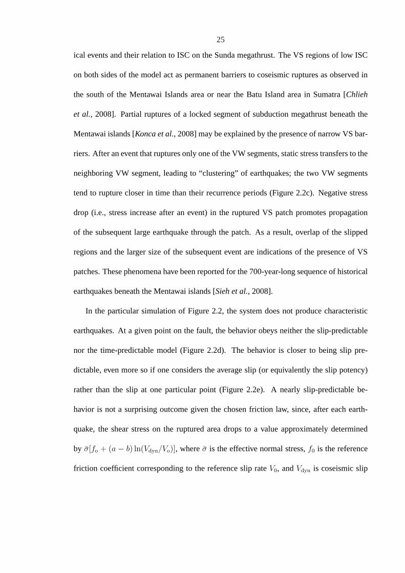
ical events and their relation to ISC on the Sunda megathrust. The VS regions of low ISC
on both sides of the model act as permanent barriers to coseismic ruptures as observed in
the south of the Mentawai Islands area or near the Batu Island area in Sumatra [Chlieh
et al., 2008]. Partial ruptures of a locked segment of subduction megathrust beneath the
Mentawai islands [Konca et al., 2008] may be explained by the presence of narrow VS bar-
riers. After an event that ruptures only one of the VW segments, static stress transfers to the
neighboring VW segment, leading to “clustering” of earthquakes; the two VW segments
tend to rupture closer in time than their recurrence periods (Figure 2.2c). Negative stress
drop (i.e., stress increase after an event) in the ruptured VS patch promotes propagation
of the subsequent large earthquake through the patch. As a result, overlap of the slipped
regions and the larger size of the subsequent event are indications of the presence of VS
patches. These phenomena have been reported for the 700-year-long sequence of historical
earthquakes beneath the Mentawai islands [Sieh et al., 2008].
In the particular simulation of Figure 2.2, the system does not produce characteristic
earthquakes. At a given point on the fault, the behavior obeys neither the slip-predictable
nor the time-predictable model (Figure 2.2d). The behavior is closer to being slip pre-
dictable, even more so if one considers the average slip (or equivalently the slip potency)
rather than the slip at one particular point (Figure 2.2e). A nearly slip-predictable be-
havior is not a surprising outcome given the chosen friction law, since, after each earth-
quake, the shear stress on the ruptured area drops to a value approximately determined
by σ[fo + (a − b) ln(Vdyn/Vo)], whereσ is the effective normal stress,f0 is the reference
friction coefficient corresponding to the reference slip rateV0, andVdyn is coseismic slip

26
rate (∼1-10 m/s). Also, the chosen friction law does not imply a threshold shear stress for
earthquakes to nucleate so that it does not favor a time-predictable behavior. The simu-
lation also shows that assessing a time- or slip-predictable behavior requires an extended
history and is difficult with just a few earthquake cycles.
2.3 Characteristics of individual earthquakes
The rupture extent in individual earthquakes is determined by two kinds of barriers: lower
prestress resulting from slip in previous events or the VS patches. In the case of low pre-
stress close to the hypocenter, only relatively small events can develop (Figure 2.3a,d).
Some events rupture the entire VW segment in which they have nucleated but arrest at
the central VS patch, where the stress drop is negative (Figure 2.3b,e). For a given size
and σ(a − b) of the VS patch, the overall prestress in the VW segments generally deter-
mines whether the two locked segments rupture together or independently. For example,
in the case (c),(f) of Figure 2.3, the average prestress over the VW segment where the rup-
ture starts is higher (τ = f0σ − 0.1 MPa) than in the case (b),(e) of Figure 2.3 (where
τ = f0σ − 0.9 MPa). As a result, the rupture propagates through the central VS patch in
the former case but not in the latter case. The distribution of prestress is spatially heteroge-
neous for all cases because the arrests of previous earthquakes and rheological boundaries
create local stress concentrations. Static stress drops of the simulated earthquakes are in
the range (1-10 MPa) typical for natural earthquakes (Figure 2.3g). The distribution of
magnitudes has a gap between 7.8 and 8, which corresponds to the difference in magni-
tudes between the earthquakes confined to one VW segment and those rupturing across the

27
central VS patch.
2.4 Quantifying the influence of a velocity-strengthening
(VS) patch on interseismic coupling and the rupture
pattern
Whether a VS patch can stop the propagation of seismic rupture depends on both the
amount of stress that is supplied to the patch by the incoming rupture and the amount
of stress increase needed for the patch to sustains seismic slip. Here, we show that the
behavior of the model, in terms of the percentage of ruptures that propagate through the VS
patch, can be described by a single non-dimensional parameter that incorporates the ratio
of these stresses and hence includes properties of both the VS and VW parts of the fault.
In Figure 2.4, we represent the effect of the sizeD and VS parameter(a − b) of the
central VS patch on the seismic rupture pattern and ISC (averaged over the patch). The
effect on seismic rupture patterns is quantified by the ratio of earthquakes that rupture both
VS segments (and thereby propagate through the VS patch) to earthquakes that rupture at
least one of the VW segments. We find that the percentage of the two-segment ruptures
and ISC are well characterized by the following non-dimensional parameter:
B =[(2π)1/2σvs(avs − bvs)D
]/ (µvwσvwbvwLvwR)1/2 , (2.1)
wherea and b are rate and state constitutive parameters,R andD are the sizes of the

28
0 60 120 180 240
0 60 120 180 240Distance along strike, x (km)
0 60 120 180
0 60 120 180Distance along strike, x (km)
0 60 120 180 240
0 60 120 180 240Distance along strike, x (km)
-10
-5
0
5
10
τ −
foσ
(M
Pa)
0
3
12
Sli
p (
m)
before EQ
after EQ
6
9
240
6 6.5 7 7.5 8 8.510
-1
100
101
102
Mw
Str
ess
dro
p (
MP
a)
0 20 1000
0.5
1.0
1.5
2.0
2.5x10⁹
Time (s)
Po
ten
cy r
ate
(m3/s
)
0 200 400 600 8000
0.2
0.6
0.8
1.0
Time after the event (days)
Post
seis
mic
sli
p (
m)
(a) (b) (c)
(d) (e) (f)
(g)
240
(h) (i)
40 60 80
decrease inpotency rate
-10
-5
0
5
10
0
3
12
6
9
-10
-5
0
5
10
0
3
12
6
9
at x = 120 km
at x = 70 km
0.4
-0.1 MPa -0.9 MPa
Figure 2.3: Characteristics of simulated earthquakes and postseismic slip. (a)-(f) Spatialdistribution of shear stress and corresponding slip for three representative events of differ-ent sizes. Shear stress minus a reference value,τ − foσ, before and after each earthquakeis shown. We define the beginning of an earthquake as the time when maximum slip rateVmax reaches 1 cm/s, and the end as the time whenVmax < 1 cm/s. Epicenters are markedby green dots. Average levels of the prestress over the VW region are indicated in panels(b) and (c). (g) Stress drops of all the events in 3000-year history. (h) Potency rates ofevents that reach the central VS patch and continue their propagation on the other side ofthe patch. The VS patch causes a marked decrease in potency rate. (i) Postseismic slip ofthe same events as in panel (h). A point within the VS patch (x = 120 km) and the VWregion (x = 70 km) are compared.

29
VW segment and the VS patch, respectively,σ is the effective normal stress,µ is shear
modulus,L is the characteristic slip, and the subscripts ’vs’ and ’vw’ are used to denote
quantities related to the VS patch and VW segment, respectively. The derivation of the
parameter is shown in Appendix 2.9. The curves of constantB in Figure 2.4 approximately
follow the constant percentages of two-segment ruptures indicated by the color scale. When
B & 4, the patch acts as a permanent barrier, in the sense that no seismic rupture propagates
through the patch over the simulated 3000-year history. WhenB . 1, the patch acts as
an intermittent barrier (i.e., more than 50i% of one-segment ruptures propagate through
the patch). ForB . 0.2, 90% of rutpures that reach the patch propagate through. When
the patch acts as a permanent barrier, the resulting earthquakes are approximately confined
within each VW segment (Figure 2.4C1; Figure 2.5C1) and are more ’characteristic’ in
their sizes, whereas a VS patch withB . 4 leads to greater variability of event sizes by
allowing larger events to occur (Figure 2.4C2,C3; Figure 2.5C2).
In the case of the VS patch withB & 4, earthquakes still occur irregularly (Fig-
ure 2.5C1), since the lengthR of each VW segment is much larger than the nucleation
sizeh∗RA. WhenR . 3h∗RA, there would be quasi-periodic repetition of ’characteristic’
earthquakes with similar rupture extent and moment, whereas, forR & 3h∗RA, more com-
plex behavior arises due to emergence of smaller earthquakes at the VW-VS transitions. In
this study, we only consider the cases with VW segments much larger than the nucleation
sizes (R À 3h∗RA), with the typical values ofh∗RA andR of the order of 2 km and 70 km,
respectively.
The non-dimensional parameterB derived for explaining the coseismic rupture patterns

30
Velocity-strengthening patch size, D (km)
0 20 40 60 80 1000
0.5
1.0
1.5
2.0
2.5x 10
9
Time (s)
Pote
ncy
rat
e (m
3/s
)
0 60 120 180 2400
5
10
15
Sli
p (
m)
0 60 120 180 2400
5
10
15
0 60 120 180 2400
5
10
15
Distance along strike (km)
C1 C2 C3
0 20 40 60 80 1000
0.5
1.0
1.5
2.0
2.5x 10
9
Time (s)0 20 40 60 80 100
0
0.5
1.0
1.5
2.0
2.5x 10
9
Time (s)
0
0.001
0.002
0.003
0.004
0.005
0.006
0.007
0.008
0.009
0.010
(a -
b)
of
vel
oci
ty-s
tren
gth
enin
g p
atch
-0.0010 10 20 30 40 505 15 25 35 45 55
C4 C5 C6
Distance along strike (km)Distance along strike (km)
Velocity-strengthening patch size, D (km)0 10 20 30 40 505 15 25 35 45 55
(a) (b)
0 20 40 60 80 100 (%)
0.5 0.6 0.7 0.8 0.9 1
Percentage of two-segment ruptures ISC averaged over the VS patch
B=
0.5
B=
8
B=
16
B=
4
B=
2B
=1B
=0.5
B=
8
B=
16
B=
4
B=
2B
=1
permanent barrier
no barrier
C1
C2
C3
C4
C5C6
B = 5 B = 2 B = 1
C1
C2
C4
C5C6
C3
Figure 2.4: Phase diagrams that illustrate the effect of the central velocity-strengtheningpatch on the long-term behavior of the model. (a) Each dot represents a simulation ofmore than 3000 years of fault slip with the parameters of the patch given by the di-agram axes. For different patch sizesD, the model size is adjusted so that the sizeR of each velocity-weakening segment is the same for all cases. Colors indicate thepercentageP of events that rupture one of VW segments and continue their propaga-tion on the other side of the VS patch (P = 0% is a permanent barrier, i.e. no rup-tures that reach the patch propagate to the other side). Curves represent the function(avs − bvs) = B (µvwσvwbvwLvwR)1/2 /[(2π)1/2σvsD], with the number on each curve cor-responding to the value ofB. (b) Simulated ISC averaged over the VS patch in the sameset of simulations as in panel (a). Panels C1-C3 show slip distributions of events corre-sponding to Cases C1-C3 indicated in the diagram (a). Potency rates of all the events thatpropagated through the patch for Cases C4-C6 are shown in panels C4-C6.

31
0 30 60 90 120 150 180 210 240
40
50
60
70
80
Distance along strike, x (km)
Acc
um
ula
ted
sli
p (
m)
0 30 60 90 120 150 180 210 240
ISC
0.20.40.60.81.0
0
40
50
60
70
80
Acc
um
ula
ted
sli
p (
m)
(b)
(d)
(c)
(a)se
ism
ic s
lip
0.20.40.60.81.0
0
tota
l sl
ip
C1C2
C1
C2
C2 C1
800
1000
1200
1400
1600
Tim
e (y
ears
)800
1000
1200
1400
Tim
e (y
ears
)
1016
+
Potency rate (m3/yr)8 6 4 2 0
40 min
9 h
B = 5
B = 2
Figure 2.5: Examples of simulated long-term fault behavior. (a) The ratio of seismic slipto total slip for Cases C1 (green) and C2 (black) in Figure 4. (b) Simulated ISC for CasesC1 (green) and C2 (black). (c) Contours of slip accumulated over 800-year history andpotency rate for Case C1. Lines have the same meaning as in Figure 2b. (d) Contours ofslip accumulated over 800-year history and potency rate for Case C2.

32
can also capture the behavior of ISC over the VS patch (Figure 2.4b), where larger values
of B correspond to smaller values of ISC over the patch. Since accumulated slip at a given
time is relatively uniform over the fault domain and equals the sum of co-, inter-, and
postseismic slip, it is not surprising that seismic behavior is related to the interseismic slip
and hence to the values of ISC. We find that a patch with only slightly reduced ISC (ISC
≈ 0.75) can systematically arrest coseismic ruptures (Figure 2.4b and Figure 2.5c). This
means that most of the total slip at the VS patch occurs postseismically (Figure 2.5c). The
presence of a permanent barrier with relatively high values of ISC (ISC≈ 0.75) corresponds
to small percentages of co- and interseismic slip compared to that of afterslip.
The examples of Figures 2.4-2.5 and additional cases in Appendix 2.10 show that the
parameterB is a good predictor of the model behavior over a wide range of parameters.
Hence one can evaluate the values ofB on faults in different tectonic settings based on
observations of seismic and aseismic slip. Doing so would enable us to constrain the pa-
rameters of fault friction.
2.5 Conclusions
This study illustrates how heterogeneities of fault rheological properties can affect individ-
ual ruptures, earthquake sequences, and the pattern of ISC. The model described here is
able to reproduce a wide range of behaviors observed on natural faults. In particular, our
model is capable of explaining the complex sequence of recent and historical events, and
their relation to ISC, on the Sunda megathrust. Our results show that areas of relatively
high values of ISC (≈0.75) can act as permanent barriers to coseismic ruptures. Areas

33
of lower ISC on natural faults may limit the rupture extent of large earthquakes, with im-
portant implications for seismic hazard. Our study suggests that VS barriers may be the
primary cause for the relative persistence of seismic rupture segmentation and asperities
observed in some tectonic settings.
We find that the probability that an earthquake breaks through the velocity-strengthening
patch can be quantified by a non-dimensional parameterB that depends on friction prop-
erties and sizes of both the velocity-strengthening patch and velocity-weakening regions.
ParameterB also characterizes the effect of the variation in friction properties on inter-
seismic coupling, which can be observed from geodetic or remote-sensing measurements.
Patches with higher values ofB result in locally lower interseismic coupling and act as
permanent barriers to seismic rupture. Patches with a range of lower values ofB lead to
a more subtle effect on interseismic coupling, decreasing it from 1 to values between 0.75
and 0.95, but such patches can have a profound effect on the pattern of seismic ruptures,
resulting in complex sequences of large earthquakes with quite different rupture area and
amount of slip in successive seismic ruptures.
Our results indicate that the presence of a VS patch can be identified from the rup-
ture kinematics of individual earthquakes and the distribution of afterslip. The source-time
functions of earthquakes that rupture through the VS patch contain double peaks (Fig-
ure 2.4C4-C6). This is because both the potency rate and the rupture velocity first decrease
as rupture propagates through the central VS patch and then increase after the rupture front
enters the neighboring VW segment. Once the rupture velocity history of an earthquake
is obtained from slip inversions, the patch size can be estimated from the duration of de-

34
creased potency rates between two peaks. A double peaked source-time function could
also arise due to a region of lower prestress on a VW fault (sometimes referred to as an
’antiasperity’). However, the two types of heterogeneities can be distinguished using post-
seismic observations, since afterslip would occur within a VS barrier (Figure 2.3i), but not
within a VW region of lower prestress. Thus, variations in seismic potency rates combined
with the distribution of afterslip can be used to infer smaller-scale heterogeneities in fric-
tion properties within a locked region of high ISC, where relatively small VS patches could
have a profound effect on the long-term seismic behavior but a subtle effect on ISC, as is
the case in a number of simulations presented here.
2.6 Appendix: Description of the fault model and param-
eters
Our fault model is based on a 2D antiplane (Mode III) framework and contains varia-
tions in steady-state friction properties. The fault motion is in the along-dip direction, and
only variations with along-strike directionx are considered, so that the fault behavior is
described by dip-parallel slipδ(x, t), slip rateV (x, t) = ∂δ(x, t)/∂t, and the relevant com-
ponent of shear stressτ(x, t). The relation between slipδ(x, t), slip velocityV (x, t), and
the corresponding shear stressτ(x, t) is given by:
τ(x, t) = τ o(x) + f(x, t)− µ
2csV (x, t) , (2.2)

35
whereµ is the shear modulus,cs is the shear wave speed,τ o is the loading stress that would
act on the interface if it were constrained against any slip, andf(x, t) is a linear functional
of prior slip over the causality cone [Rice, 1993;Lapusta et al., 2000]. The last term,
known as radiation damping, is extracted from the functionalf(x, t) so thatf(x, t) can be
evaluated without concern for singularities. The details of elastodynamics and simulation
methodology for the model are described inLapusta et al.[2000].
Earthquakes are simulated as a part of spontaneously occurring earthquake sequences
on a fault that is subjected to slow, tectonic-like loading. This approach allows us to study
naturally developing earthquakes in our models, with conditions before the nucleation orig-
inating from the previous stages of earthquake occurrence rather than from arbitrarily se-
lected prestress. Our simulations resolve all stages of each earthquake episode: the aseismic
nucleation process in gradually varying zones of accelerating slip, the subsequent inertially
controlled event (unstable slip) with realistic slip rates and rupture speeds, the postseismic
slip, and the interseismic quasi-static deformation between events.
The fault is governed by rate and state friction with the aging form of state variable
evolution. For situations with time-independent effective normal stressσ, the shear strength
τ is expressed as
τ = σ
[f0 + a ln
(V
V0
)+ b ln
(V0θ
L
)], (2.3)
dθ
dt= 1− V θ
L, (2.4)
wherea > 0 and b are rate and state constitutive parameters,V is slip rate,f0 is the
reference friction coefficient corresponding to the reference slip rateV0, θ is a state variable

36
which can be interpreted as the average age of the population of contacts between two
surfaces, andL is the characteristic slip for state evolution [e.g.,Dieterich, 1978, 1979;Rice
and Ruina, 1983;Ruina, 1983;Dieterich and Kilgore, 1994]. The actual fault resistance to
sliding in our model is given by rate and state friction regularized at zero slip velocity [e.g.,
Lapusta et al., 2000].
We use parameters applicable for natural faults or derived from laboratory experiments
except for characteristic slipL. The value ofL used is 8 mm, larger than the laboratory
values of the order of 1-100µm, to make large-scale simulations numerically tractable.
Unless otherwise noted, we useµ = 30 GPa,cs = 3.3 km/s,σ = 50 MPa,f0 = 0.6,V0 = 10−6
m/s,avw = 0.010, andbvw = 0.015, where the subscript ’vw’ is used to denote quantities
related to the VW segments.
2.7 Appendix: Criteria for spatial discretization and time-
stepping parameters
The simulated fault domainλ = 480 km is composed of the 240-km region where friction
is applied, and the 240-km loading region of the prescribed slip rate. In our numerical
simulations, the spatial cell size∆x needs to be small enough to properly resolve both the
aseismic nucleation process and the cohesive zone size during dynamic rupture propaga-
tion. In all of our simulations, good resolution of the cohesive-zone size is a more strict
constraint on the spatial discretization. The ratioΛ/∆x of the cohesive zone sizeΛ to the
cell size∆x = 29 m needs to be 3-5 or larger for faults with rate and state friction [Kaneko

37
et al., 2008]. The value ofΛ in a typical scenario is≈ 200 m and henceΛ/∆x > 5.
The resulting ratioh∗RA/∆x = 2µbL/[π(b − a)2σ∆x] = 63, whereh∗RA is the estimate of
the nucleation size fora/b & 0.5 given byRubin and Ampuero[2005], is high enough to
properly resolve the nucleation processes.
Time t is discretized into variable time steps. The minimum value of the time step is
related to the time∆tcell = ∆x/cs needed for the shear wave to propagate through one
spatial cell; it is given by0.5∆x/cs = 0.044 s. Such a small value of∆tmin is needed
because slip in one time step must be comparable to or smaller than the characteristic slip
L of the friction law to resolve the state-variable evolution. The largest time step allowed in
all simulations is 0.2 years. In the mode-dependent convolution truncation,Tw(1) = λ/cs
andqw = 4. A typical simulation with 3000 years of simulated slip history takes 5 days on
a single 2.33-GHz processor.
2.8 Appendix: Definition of interseismic coupling (ISC)
We consider interseismic periods at each point on the fault to correspond to the time periods
whenV (x, t) < Vpl, whereVpl is the plate rate. Such periods are illustrated in Figure 2.6.
For the interseismic periods, spatially and temporally variable ISC can be defined as1 −
V (x, t)/Vpl. To report a temporally averaged value of ISC for each fault locationx, we
compute:
ISC(x) = 1− δcumint (x)/[VplT
cumint (x)] , (2.5)

38
150 200 250 300 350-2
-1
0
1
2
3
4
time (year)
log(V
/Vp
l)
δint
Tint
Figure 2.6: Illustration of interseismic periods in our simulations. Slip velocityV at thecenter of the VS patch is shown for one of the simulations.Tint andδint are the durationand slip, respectively, during one of the interseismic periods, defined as the time periodswith V (x, t) < Vpl. To compute a temporally averaged ISC, we use the sum ofTint andδint
for all interseismic periods in formula (2.5).
whereT cumint is sum of the interseismic time intervals at the locationx for the entire simula-
tion andδcumint is the slip accumulated atx over all interseismic periods.
2.9 Appendix: Derivation of the non-dimensional model
parameter B
The behavior of the model in terms of the percentage of ruptures that propagate through the
VS patch (Figure 2.4) can be described by a single non-dimensional parameter that incor-
porates properties of both VS and VW parts of the fault. Let us consider the condition under
which a single seismic rupture that has reached the VS patch would propagate through the
patch. During fast seismic slip, shear stress at the VS patch would go up, which means that
the patch requires additional shear stress∆τseis over its entire lengthD to sustain seismic

39
slip. The rupture that has reached the VS patch increases shear stress at the patch due to
stress concentration in front of the rupture; if that stress increase is adequate, the rupture
would propagate through the patch. Hence we define the non-dimensional parameter as
B =∆τseisD
∆T, (2.6)
where∆T is the stress increase on the patch due to the rupture of the nearby VW segment
integrated through the patch. We would expect the rupture to always propagate through
the patch ifB ≤ 1. If B > 1, the rupture may still propagate through the patch after
combined stress deposition due to several earthquakes, unless the stresses are released in
the postseismic and interseismic periods. Hence forB > 1, we expect smaller percentage
of earthquakes to propagate through the patch.
Let us estimate∆τseis. Prior to the arrival of coseismic rupture, the shear stress inside
the patch is given by:
τ ivs = σvs
[f0 + (avs − bvs) ln
(V bg
vs /V0
)], (2.7)
whereV bgvs is the interseismic slip rate in the VS patch. During seismic slip with slip rate
V dynvs , shear stress in the patch can be approximated as
τdvs = σvs
[f0 + (avs − bvs) ln
(V dyn
vs /V0
)]. (2.8)

40
Hence
∆τseisD = σvs(avs − bvs)D ln(V dyn
vs /V bgvs
). (2.9)
Now let us consider∆T . From (2.2), shear stress distributionτ(x) during a seismic
event can be written as
τ(x) = τbefore(x) + f(x, t)− µ
2csV (x) , (2.10)
whereτ o(x) in (2.2) is taken to be shear stress before the event andf(x, t) is redefined
accordingly. Integrating (2.10) over the entire fault, we have
∫
x
τ(x)dx =
∫
x
τbefore(x)dx− µ
2cs
∫
x
V (x)dx , (2.11)
since the integral overf(x, t) is zero [Zheng and Rice, 1998]. The last term on the right-
hand side is small compared to others, since slip velocity is appreciable only in relatively
small regions next to the crack tips. Ignoring that term, we obtain
∫
x
[τ(x)− τbefore(x)
]dx = 0 , (2.12)
or∫
vw
[τ(x)− τbefore(x)
]dx+
∫
vs
[τ(x)− τbefore(x)
]dx = 0 . (2.13)
Considering the situation where one of the VW segments has ruptured and transferred stress
onto the surrounding VS regions, we get:

41
∆T = (1/2)
∫ R
0
∆τvw(x)dx = ∆τvwR/2 , (2.14)
where∆τvw and∆τvw are the coseismic stress drop and its average value over the velocity
weakening segment, respectively. Equation (2.14) assumes that half of the shear stress is
transferred to the central VS patch (with the other half being deposited onto the larger VS
region on the other side of the ruptured segment) and that the velocity-strengthening patch
is large enough to host most of stress concentration due to rupture.
To obtain an analytical expression for the average stress drop∆τvw, we use the model
of the Mode III quasi-static 2D shear crack with uniform prestress in an infinite elastic
medium. The energy release rateG = K2III/(2µvw), whereKIII = ∆τvw
√πR/2 [e.g.,
Broberg, 1999], is balanced by the fracture energyGc, giving
∆τvw =
(4µvwGc
πR
)1/2
. (2.15)
For the rate and state friction with the aging form of state variable evolution as used in this
work, the fracture energyGc is given byRubin and Ampuero[2005]
Gc =σvwbvwLvw
2
[ln(V dyn
vw /V bgvw )
]2. (2.16)
Then (2.15) becomes
∆τvw =
(2µvwσvwbvwLvw
πR
)1/2
ln(V dynvw /V bg
vw ) . (2.17)

42
Substituting the obtained estimates into (2.6), we obtain
B =(2π)1/2σvs(avs − bvs)D ln
(V dyn
vs /V bgvs
)
(µvwσvwbvwLvwR)1/2 ln(V dyn
vw /V bgvw
) ≈ (2π)1/2σvs(avs − bvs)D
(µvwσvwbvwLvwR)1/2. (2.18)
In our simulations, the factorln(V dyn
vs /V bgvs
)/ ln
(V dyn
vw /V bgvw
) ≈ 0.7, but we ignore this
factor in (2.18) for simplicity. Figure 2.4 shows the correspondence between the simulated
results and the parameterB for variations in the size and friction properties of the VS patch.
Note thatB = 1 corresponds to about 60% of ruptures propagating through the VS patch,
not 100% as expected based on its definition, which is likely the result of the assumptions
made in derivingB. However, the parameter is a good predictor of the model behavior,
in the sense that the value ofB predicts the percentage of ruptures that would propagate
through as the model parameters are varied, as described in sections 2.4 and 2.10.
2.10 Appendix: Relation among the non-dimensional pa-
rameter B, the percentage of two-segment ruptures
P, and interseismic coupling (ISC) over a range of
parameters
To explore the usefulness of parameterB, we perform a series of simulations similar to the
ones discussed in section 2.4 (Figure 2.4) but with variations in several parameters entering
the expression (2.18). In each set of simulations, we change one model property from the
case of Figure 2.4 and consider the influence of the sizeD and(a− b) of the VS patch on

43
Table 2.1: The range of model parameters used to explore the correspondence between thenon-dimensional parameterB and the model behavior (Figure 2.8).
Parameter Symbol Range
Shear modulus µ 30, 60 GPaCharacteristic slip distance in vw Lvw 8, 24 mmCharacteristic slip distance in vs Lvs 8, 24 mmEffective normal stress in vw σvw 25, 50 MPaEffective normal stress in vs σvs 25, 50 MPaThe size of the vw segment R 30− 100 kmThe size of the vs patch D 5− 50 kmRate and state parametera in vw avw 0.0025− 0.025Rate and state parametera in vs avs 0.010− 0.020Rate and state parameterb in vw bvw 0.0050− 0.030Rate and state parameterb in vs bvs 0− 0.020
percentage of two-segment ruptures. We find that the curves of constantB approximately
correspond to the same color range in all cases we consider (e.g., in Figure 2.7, the curves
with B = 2 correspond to light green to dark green), suggesting thatB is a good predictor
of the percentage of two-segment ruptures in cases with different parameters considered
here.
In Figure 2.8, we quantify the goodness of the correspondence between the non-dimensional
parameterB and the behavior of the model for the simulations shown in Figure 2.4, Fig-
ure 2.7, and additional simulations with model parameters given in Table 2.1. We find that
the relation betweenB and the percentage of two-segment rupturesP is non-linear and can
be fitted with the following function:
Pest = 100(4−B)/(4 +B) for B ≤ 4
= 0 for B > 4 . (2.19)

44
0 20 40 60 80 100 (%)
B=
0.5
B=
4
B=
2B
=1
Percentage of two-segment ruptures
Velocity-strengthening patch size, D (km)
0
0.001
0.002
0.003
0.004
0.005
0.006
0.007
0.008
0.009
0.010
(a -
b)
of
vel
oci
ty-s
tren
gth
enin
g p
atch
-0.0010 10 20 30 40 505 15 25 35 45 55
Velocity-strengthening patch size, D (km)
0
0.001
0.002
0.003
0.004
0.005
0.006
0.007
0.008
0.009
0.010
(a -
b)
of
vel
oci
ty-s
tren
gth
enin
g p
atch
-0.0010 10 20 30 40 505 15 25 35 45 55
Velocity-strengthening patch size, D (km)
0
0.001
0.002
0.003
0.004
0.005
0.006
0.007
0.008
0.009
0.010
(a -
b)
of
vel
oci
ty-s
tren
gth
enin
g p
atch
-0.0010 10 20 30 40 505 15 25 35 45 55
Velocity-strengthening patch size, D (km)
0
0.001
0.002
0.003
0.004
0.005
0.006
0.007
0.008
0.009
0.010
(a -
b)
of
vel
oci
ty-s
tren
gth
enin
g p
atch
-0.0010 10 20 30 40 505 15 25 35 45 55
(a) (b)
(c) (d)
B=
8
B=16
B=
4
B=
1
B=
8
B=16
B=
2
B=
0.5
B=
4
B=
2
B=
1
B=
8
B=
0.5
B=
0.5
B=
4
B=
2B
=1
B=
8
Figure 2.7: Phase diagrams similar to the one in Figure 2.4a, but for models with differentparameters, to verify the usefulness of parameterB. The parameters in Figure 2.4 areσvw
= σvs = 50 MPa,avw = 0.010, bvw = 0.015, andR = 72.5 km. Panels (a)-(d) each showresults for a set of simulations with one or two of these parameters modified. (a) Case withσvs = 25 MPa. (b) Case withR = 32.5 km. (c) Case withavw = 0.025 andbvw = 0.030.(d) Case withavw = 0.005 andbvw = 0.015.

45
wherePest would be the value ofP estimated based onB. The valueB = 4 corresponds
to P = 0% (a permanent barrier). We also find that the empirical relation betweenB and
the simulated ISC averaged over the patch is non-linear and given by
ISCest = 1− 0.085B0.62 , (2.20)
whereISCest would be the value of ISC estimated based onB. Combining (2.19) and
(2.20), and rewritingP as a function of ISC, we obtain
P = 100
[4− (
1−ISC0.085
)1/0.62
4 +(
1−ISC0.085
)1/0.62
]for ISC ≥ 0.8
= 0 for ISC < 0.8 . (2.21)
As expected, the relation between the percentage of two-segment rupturesP and ISC can
be well approximated by (2.21) (Figure 2.8e). Note that a patch with only slightly reduced
ISC (ISC≈ 0.75) can systematically arrest coseismic ruptures.
We conclude that the non-dimensional parameterB is a good predictor of both coseis-
mic and interseismic slip over a wide range of parameters.

46
0 1 2 3 4 50
20
40
60
80
100
B
Per
centa
ge
of
two-s
egm
ent
ruptu
res,
P
-100 -50 0 50 1000
100
200
300
400
500
Residual, P - Pest
Num
ber
correlation = 0.95
+15 range = 89%
(a) (b)
0 5 10 150.5
0.6
0.7
0.8
0.9
1
0.70 0.75 0.80 0.85 0.90 0.95 10
20
40
60
80
100
B
ISC
Per
centa
ge
of
two-s
egm
ent
ruptu
res,
P
ISC
(c) (d)
(e) Residual, ISC - ISCest
-0.2 -0.1 0 0.1 0.20
50
100
150
200
250
Num
ber
correlation = 0.98
+0.04 range = 90%
Figure 2.8: Relation between the non-dimensional parameterB and the percentage of two-segment rupturesP (panels a, b), and simulated ISC (panels c, d) over a range of param-eters given by Table 2.1. (a) Each dot corresponds to simulatedP with a different set ofparameters. The red curve is a functionP = 100(4 − B)/(4 + B) for B ≤ 4 andP = 0for B > 4. Note that the set of parameters corresponding to velocity-neutral (avs = bvs)cases are excluded. (b) A histogram that shows good agreement between the predictionand the simulatedP . (c) Each dot corresponds to a simulated value of ISC averaged overthe VS patch with a different set of model parameters. The red curve is a function ISC= 1 − 0.085B0.62. (d) A histogram that shows good agreement between the predictionand the simulated ISC. (e) Relation between the percentage of two-segment rupturesP andsimulated ISC of the VS patch. The red curve is the prediction based on formula (2.21).
47
Chapter 3
Variability of Earthquake Nucleation inContinuum Models of Rate and StateFaults
In this Chapter, we simulate, in the context of earthquake sequences, several plausible
scenarios of earthquake nucleation on faults embedded in an elastic medium and governed
by rate and state friction, and explore variability in simulated earthquake nucleation due to
fault heterogeneities and different loading conditions.
This Chapter is based on Sections 2-4 of the paper “Variability of earthquake nucleation
in continuum models of rate-and-state faults and implications for aftershock rates” by Y.
Kaneko and N. Lapusta (J. Geophys. Res., 2008).
3.1 Previous theoretical studies of earthquake nucleation
Studies of earthquake nucleation have concentrated on a theoretically interesting and prac-
tically important topic: the nucleation size, i.e., the size of the slipping zone right before an
earthquake. Several theoretical estimateshnucl of the nucleation size have been proposed,

48
all of them in the form:
hnucl =ηGL
σF, (3.1)
whereη is a model-dependent parameter of order one,G is the shear modulus, andF is a
function of rate and state parametersa andb. Rice and Ruina[1983], Ruina [1983], and
Rice et al.[2001] considered linear stability of perturbations from steady-state sliding and
determined thatF = b− a. Dieterich[1992] assumed that nucleation processes accelerate
fast enough forV θ/L À 1 to hold and obtainedF = b. The estimate ofDieterich [1992]
was later confirmed in meter-scale rock friction experiments [Dieterich and Kilgore, 1996].
Rubin and Ampuero[2005] proposed that there are two regimes controlled by the ratio
a/b. If a/b . 0.37, the nucleation proceeds in a fixed region of the size given by (3.1)
with F = b, as in the estimate byDieterich [1992]. If a/b & 0.5, the nucleation process
resembles an expanding crack and the nucleation size asymptotically approaches (3.1) with
F = (b − a)2/b. Note that all three estimates match, within factors of order 1, fora ¿ b
which impliesb−a ≈ b. Fora approachingb (friction properties close to velocity neutral),
both Rice-Ruina and Rubin-Ampuero estimates predict increasingly larger nucleation sizes
(although Rubin-Ampuero estimate increases significantly faster). This is consistent with
the fact that velocity-strengthening regions cannot spontaneously produce unstable sliding,
and hence the nucleation size fora ≥ b can be considered infinite.

49
3.2 2D continuum models of earthquake nucleation
We consider earthquake nucleation on a planar fault embedded into an elastic medium of
homogeneous elastic properties with the shear wave speedcs = 3.0 km/s, shear modulus
G = 30 GPa, and Poisson’s ratioν = 0.25. On the fault, a potentially seismogenic patch
borders regions steadily moving with a prescribed slip rateVL = 1 mm/yr, as illustrated
in Figure 3.1A. That steady motion provides loading in our models. The loading slip rate
VL = 1 mm/yr is on the low end of typical plate rates but it could be representative of steady
slip achieved locally on faults, especially in the case of secondary faults or multiple fault
strands. The fault resistance to sliding is given by rate and state friction regularized at zero
slip velocity [Rice and Ben-Zion, 1996;Lapusta et al., 2000]. The value of characteristic
slip L in simulations presented in Chapters 3 and 4 is 80µm (unless noted otherwise), as
laboratory-like values ofL (of order 1-100µm) are required to account for the presence of
small (M ∼ 0) earthquakes on natural faults [e.g.,Lapusta and Rice, 2003].
Two simplified fault models that we use to create two conceptually different scenarios
of earthquake nucleation are described in sections 3.2.1-3.2.2 and illustrated in Figure 3.1B.
More details are given in appendix 3.6. The friction and stress parameters of the models
are summarized in Table 3.1 and Figure 3.2. To simulate spontaneous slip accumulation in
terms of earthquake sequences, we use the boundary integral method developed byLapusta
et al. [2000] andLapusta[2001].

50
Model with a weaker patch
Model with rheological transition
Distance along fault, x
Distance along fault, z
velocity weakening
velocitystrengthening
velocityweakening
velocitystrengthening
x
yz
seismogenic depth
(a)
VL
VL
region where
friction acts
(b)
x
z
Figure 3.1: (A) 3D schematics of a planar fault in an elastic medium. This study employssimplified 2D models and focuses on a small region indicated by the square. The faultregion governed by rate and state friction (shown in gray) is loaded by relative motion aboveand below the region with a prescribed slip rateVL. (B) Schematics of fault properties inthe simplified 2D continuum models. In the model with a weaker patch (top), the faulthas steady-state velocity-weakening properties everywhere and contains a patch of lowereffective normal stress indicated by a square. In the model with rheological transition(bottom), a steady-state velocity-weakening region is surrounded by steady-state velocity-strengthening regions.
Table 3.1: Friction-related parameters of both models. In the model with a weaker patch,σ = 50 MPa in the patch andσ = 55.6 MPa outside the patch. The indicated values ofa andb are valid for the entire fault in the model with a weaker patch and for the part ofthe steady-state velocity-weakening region of the model with rheological transition wherea andb are constant.
Parameter Symbol Value
Reference slip velocity V0 10−6 m/sReference friction coefficient µ0 0.6Characteristic slip distance L 80.0 µmEffective normal stress σ 50.0 MPaRate and state parametera a 0.015 or 0.0015Rate and state parameterb b 0.019 or 0.0055

51
3.2.1 Model with a weaker patch
The first model incorporates a weaker patch of 10% lower effective normal stress. The
model is based on the crustal-plane model [Lapusta, 2001]; it restricts the fault to motions
parallel to the along-strike directionx, eliminates the fault depth by considering depth-
averaged quantities, and retains variations only in the along-strike directionx. These mod-
ifications turn the 2D planar fault into a 1D along-strike analog (Figure 3.1B), with the
fault behavior described by strike-parallel slipδ(x, t), slip velocity (or slip rate)V (x, t) =
∂δ(x, t)/∂t, and the relevant component of shear stressτ(x, t). Compressive effective nor-
mal stressσ(x) does not depend on time in the cases considered. At the ends of the fault,
there are zones of zero initial shear stress to stop dynamic events (Figure 3.2). Hence the
extent of the fault capable of sustaining dynamic events is 1000 m. A more physical ap-
proach would be to replace the zero-stress regions with regions of velocity-strengthening
properties, but that would create alternative places for earthquakes to nucleate, and in this
model we would like to avoid such complexities. By making earthquakes nucleate in the
designated place, i.e., at the weaker patch in the middle of the fault, we can control how
heterogeneous the imposed conditions are in the nucleation region.
We have done a number of simulations of earthquake sequences in this model, varying
the values of parametersa (0.0015-0.015),b (0.0055-0.019),L (10-120µm), and the size
of the weaker patch (2-200 m). We present results for three representative cases, all with
L = 80 µm:
Case 1: The size of the weaker patch, 100 m, is much larger than the nucleation size,
which is less than 30 m in this case. Hence there is no imposed heterogeneity within the

52
-1000 -500 0 500 10000
10
20
30
40
50
60
Str
ess
(MP
a)
Distance along fault, x (m)
Model with a weaker patch
τo
σ
-1000 -500 0 500 1000-0.01
-0.005
0
0.005
0.01
0.015
0.02
Val
ue
of a
an
d (
a -
b)
Distance along fault, x (m)
a
(a − b)
0 10 20 30 40 50 60
300
200
100
0
-100
-200
-300
Stress (MPa)
Model with rheological transition
Dis
tan
ce a
lon
g f
ault
, z (
m)
-0.01 -0.005 0 0.005 0.01 0.015 0.02
300
200
100
0
-100
-200
-300
Value of a and (a - b)
Dis
tan
ce a
lon
g f
ault
, z (
m)
Figure 3.2: Top panels: Distributions of effective normal stressσ and initial shear stressτ o
in the two models. In the model with a weaker patch, the region of lowerσ is introducedin the middle of the fault to encourage earthquake nucleation there. The size of the weakerregion varies in different cases studied. Bottom panels: Examples of distributions of rateand state parametersa and(a− b) in the two models. Locations witha− b = 0 correspondto rheological transitions from velocity-weakening to velocity-strengthening steady-statefriction. We varya andb in the presented cases but keep(a− b) the same in all cases.

53
nucleation zone. Valuesa = 0.015 andb = 0.019 are used (Figure 3.2), which are typical
of laboratory experiments. Nucleation proceeds under stress conditions that are relatively
homogeneous compared to other cases. However, in this and all other cases, shear stress
concentrations do develop, as expected, at the edges of the slowly varying zone of faster
slip.
Case 2: The size of the weaker patch, 10 m, is a significant fraction of the nucleation
zone that develops. Nucleation proceeds under imposed conditions of heterogeneous nor-
mal stress within the nucleation zone. The other parameters are the same as in Case 1.
Case 3: The value ofa = 0.0015 is 10 times smaller than that of Cases 1 and 2. This
value is representative of the ones inferred from aftershock observations based on the model
of Dieterich [1994], assuming overburden normal stress minus hydrostatic pore pressure
[Gross and Kisslinger, 1997;Gross and Burgmann, 1998;Toda et al., 1998, 2005]. The
parameterb = 0.0055 is chosen to keep(b− a) the same as in Cases 1 and 2, ensuring the
same steady-state velocity-weakening properties. The size of the weaker region, 10 m, is
a significant fraction of the nucleation zone, as in Case 2. Note that the ratioa/b is 0.27
in this Case, whilea/b = 0.79 for Cases 1 and 2. According to the study ofRubin and
Ampuero[2005], this represents a qualitative difference, as explained in section 3.1.
3.2.2 Model with rheological transition
The second model contains variations in steady-state friction properties that create rheo-
logical transitions. It is analogous to the depth-variable model ofLapusta et al.[2000].
The fault motion is still in the along-strike directionx, but only variations with depthz are

54
considered, so that the fault behavior is described by strike-parallel slipδ(z, t), slip veloc-
ity (or slip rate)V (z, t) = ∂δ(z, t)/∂t, and the relevant component of shear stressτ(z, t).
Unlike the model studied inLapusta et al.[2000], the model here does not include the free
surface. The effective normal stressσ is constant along the entire fault (Figure 3.2).
We have done a number of simulations in this model, varying the values ofa andb in
the velocity-weakening region (0.0015-0.015 and 0.0055-0.023, respectively) andL (20-
160µm). We present results for two representative cases, both withL = 80 µm.
Case 4:a = 0.015 andb = 0.019 in the steady-state velocity-weakening region, as in
Cases 1 and 2 of the model with a weaker patch. Full distributions ofa andb are shown
in Figure 3.2. This variation is qualitatively similar to the one inRice[1993] andLapusta
et al. [2000]. The distributions ofa andb are asymmetric with respect to the middle of the
fault, so that simulated earthquakes nucleate at one of the rheological transitions.
Case 5:a = 0.0015 andb = 0.0055 in the steady-state velocity-weakening region, as
in Case 3. Throughout the fault domain, this Case has 10 times smallera than Case 4 and
suchb that the distribution of(a − b) is the same in both Cases. The same distribution of
(a− b) ensures that rheological transitions are at the same locations in both cases.

55
3.3 Simulated nucleation processes
3.3.1 Nucleation processes due to weaker patches and importance of
normal stress heterogeneity
As an example of fault slip simulated in the model with a weaker patch, consider the earth-
quake sequence for Case 1 (Figure 3.3A). Earthquakes nucleate in the middle of the fault,
due to the weaker patch. The earthquakes then spread bilaterally along the strike of the
fault; the dashed lines show slip accumulation every 0.01 s during the dynamic rupture.
When the rupture reaches zero-stress barriers, it arrests. The interseismic period is 28
years. We take the nucleation process of the third event as the representative one for this
Case; the corresponding part in Figure 3.3 is surrounded by a small rectangle.
To study nucleation sizes and aftershock rates, we need to define when the nucleation
process ends and the dynamic event begins. InDieterich [1992] andDieterich [1994],
quasi-static equations were used, and their solution ceased to exist (i.e., slip velocities be-
came infinite) when inertial effects would have been important in the complete formulation.
The time at which the solution ceased to exist was taken as the time of instability onset.
Since our simulations fully account for inertial effects and capture the smooth transition
between the quasi-static phase and dynamic rupture, defining the beginning of an earth-
quake is not so simple. We use the criterion based on rupture speed and take, as the onset
of instability, the time at which a tip of the actively slipping zone moves with the speed
that exceeds a fraction (10%) of the shear wave speed of the surrounding elastic medium.
The tips of the actively slipping zone are found as the locations of shear stress concentra-

56
-1000 -500 0 500 100050
80
110
140
170
Distance along fault, x (m)
Acc
um
ula
ted
sli
p (
mm
)
(a) Model with a weaker patch
30 50 70 90 110
300
200
100
0
-100
-200
-300
Accumulated Slip (mm)
Dis
tan
ce a
lon
g f
ault
, z (
m)
(b) Model with rheological transition
Figure 3.3: Examples of earthquake sequences simulated in the model with a weaker patch(panel A) and in the model with rheological transition (panel B). Solid lines show slip accu-mulation every 2 years. Dashed lines are intended to capture dynamic events and are plottedevery 0.01 seconds during the simulated earthquakes. For each earthquake, the dashed linesare shown from 0.05 seconds before our definition of the onset of an earthquake (rupturespeed reaching 10% of the shear wave speed) until the maximum slip velocity on the faultreduces to 1 mm/s. The nucleation process of a representative earthquake is indicated by arectangle in both panels.

57
tion. The sliding region changes very slowly in space during the quasi-static deformation,
and extends with rupture speeds comparable to the shear wave speed during the dynamic
phase. Hence this rupture definition allows us to appropriately capture the transition. An
alternative approach would be to define the beginning of an earthquake as the time when
slip velocities reach a certain value, e.g., 0.1 m/s, either at a particular location or as a max-
imum on the fault. Note that the two criteria are related, as faster slip velocities correspond
to larger rupture speeds.
Representative nucleation processes for Cases 1-3 are shown in Figure 3.4. The dashed
lines in panels A-C show slip accumulation every 0.01 s starting with 0.05 s before our
definition of the beginning of an earthquake. The first five dashed lines are almost on top
of each other, signifying still relatively slow slip and slow expansion of the sliding region.
The sixth line shows much faster slip and expansion, indicating the beginning of a dynamic
event. The panels D-F illustrate the imposed distribution of effective normal stress and the
approximate extent of the spontaneous nucleation zone.
The comparison of Cases 1 and 2 shows an interesting result. The presence of slight
normal stress heterogeneity within the nucleation zone in Case 2 leads to 1.5 times larger
nucleation size for that Case, 36 m vs. 24 m for Case 1. Average normal stress is larger in
Case 2, with all other parameters being the same, and all existing estimates of earthquake
nucleation sizes discussed in section 3.1 would predict that the nucleation size should be
smaller in Case 2 than in Case 1, but the opposite is observed. The antiplane estimate
of nucleation size byRubin and Ampuero[2005] gives 36 m for the parameters of these
cases. Since we use a depth-averaged model, the directionx is affected by a factor of

58
-30 -20 -10 0 10 20 30107
109
111
113
115
Acc
um
ula
ted s
lip (
mm
)
a = 0.015, a/b = 0.79weaker patch = 100 m
CASE 1
Homogeneous normal stress
within the nucleation zone
(a)
-30 -20 -10 0 10 20 3030
40
50
60
Distance along fault, x (m)
σ(M
Pa)
(d)
-30 -20 -10 0 10 20 30112
114
116
118
120
a = 0.015, a/b = 0.79weaker patch = 10 m
CASE 2
Heterogeneous normal stress
within the nucleation zone
(b)
-30 -20 -10 0 10 20 3030
40
50
60
Distance along fault, x (m)
(e)extent of the
nucleation zone
-30 -20 -10 0 10 20 30
93
95
97
99
a = 0.0015, a/b = 0.27weaker patch = 10 m
CASE 3
Same as CASE 2 except
smaller values of a and b
(c)
-30 -20 -10 0 10 20 3030
40
50
60
Distance along fault, x (m)
(f)
92 96 100 104 108 112
30
20
10
0
-10
-20
-30
-40
Accumulated slip (mm)
Dis
tance
alo
ng f
ault
, z (
m)
a = 0.015, a/b = 0.79
CASE 4
Transition between
creeping and locked region
(g)
33 35 37 39 41
10
0
-10
-20
-30
-40
Accumulated slip (mm)
a = 0.0015, a/b = 0.27
CASE 5
Same as CASE 4 except
smaller values of a and b
(h)
Figure 3.4: (A)-(C) Nucleation processes at weaker patches. Cases 1-3 correspond to eitherdifferent sizes of the weaker patch or different constitutive parametersa andb. The otherparameters are the same for all three cases. Panels D-F show the distribution of effectivenormal stressσ in a region that includes the nucleation zone. Double arrows indicate theextent of the nucleation zone for each case. (G)-(H) Nucleation processes at rheologicaltransition. Cases 4 and 5 correspond to different constitutive parametersa andb. Solid anddashed lines in panels A-C and G-H have the same meaning as in Figure 3.3. Shaded areascorrespond to velocity-strengthening regions.

59
Z = 1/(1 − ν) = 4/3 (appendix 3.6) and hence the estimate becomes 48 m. This is
broadly consistent with the nucleation sizes in Cases 1 and 2, in the sense that the estimate
gives a close upper bound. Note that the energy balance in the expanding-crack solution
of Rubin and Ampuero[2005], when adopted to the normal-stress heterogeneity of Case
2, would be qualitatively consistent with the larger nucleation size for Case 2 (A. Rubin,
personal communication, 2007). This result demonstrates that stress heterogeneities on
faults can have significant, and sometimes counterintuitive, effect on nucleation processes.
Case 3, with a smaller value ofa/b, behaves differently from Cases 1 and 2. The
nucleation size in Case 3 is about 29 m. We simulated a number of cases similar to Case 3
but with different sizes of the weaker patch, including the case in which the weaker patch
was much larger than the resulting nucleation size. In all those cases, the nucleation size
changed very little compared to Case 3. This means that the effect of heterogeneity on the
nucleation size is diminished for sufficiently small values ofa/b. We also find that smaller
values ofa/b lead to shorter periods of interseismic deformation between two successive
earthquakes. In Case 3, the interseismic period is 23.8 years, smaller than the interseismic
period of 29.1 years in Case 2, despite the fact that(b− a) is the same in the two cases.
3.3.2 Nucleation processes due to rheological transitions
An earthquake sequence simulated in the model with rheological transition is shown in Fig-
ure 3.3B, using Case 4 as an example. The solid lines are plotted every 2 years and show
the continuous slow sliding (creep) of the steady-state velocity-strengthening regions. That
slow slip creates stress concentration at its tip and penetrates into the velocity-weakening
60
region. In due time, an earthquake nucleates close to the transition; its progression is shown
by dashes lines. After an earthquake arrests, the velocity-strengthening region experiences
accelerated sliding, or afterslip, due to the transferred stress. The interseismic period be-
tween two successive events is 32 years. We take the nucleation process of the forth event
as the representative one for this Case; the relevant part of Figure 3.3 is surrounded by a
small rectangle.
Representative nucleation processes for Cases 4 and 5 are shown in Figure 3.4. Nucle-
ation of the simulated earthquakes occurs within the velocity-weakening region, but close
to transition to velocity-strengthening friction (panels G and E; the transition is atz = −32
m in both cases). Due to interactions with the nearby creeping region, such nucleation pro-
ceeds under temporally and spatially non-uniform stress field. The different values fora
andb (with the same value ofb−a) in Cases 4 and 5 lead to notable differences in nucleation
processes. The nucleation sizes in Cases 4 and 5 are different and approximately consistent
with the estimates ofRubin and Ampuero[2005], which are2µLb/(πσ(b− a)2) = 36 m
for Case 4 and2.74µL/(σb) = 24 m for Case 5. Note thatRubin and Ampuero[2005]
gave formulae for half of the nucleation size, but we use full nucleation sizes here. In our
simulations, the nucleation sizes are 35 to 40 m for Case 4 and 18 to 24 m for Case 5, as
can be estimated from Figure 3.4.
As in the model with a weaker patch, smaller values ofa/b result in shorter interseismic
periods, but the effect is much stronger in the model with rheological transition. In Case
5, the interseismic period is 18 years, almost twice shorter than the interseismic period of
32 years in Case 4. In the model with a weaker patch, the interseismic period is dictated

61
0 5 10 15 20 25 30
Time to instability (year)
10-17
10 -15
10 -13
10 -11
10 -9
10 -7
Sli
p v
elo
city
(m
/s)
10-17
10 -15
10 -13
10 -11
10 -9
10 -7
Sli
p v
elo
city
(m
/s)
Time to instability (year)10
-5
10 -4
10 -3
10 -2
10 -1
100
101
(a) (b)
Case 1
Case 2
Case 4
Case 1
Case 2
Case 4
Figure 3.5: Slip-velocity evolution during one earthquake cycle for representative pointsinside nucleation zones, on linear (panel A) and logarithmic (panel B) time scales. Time toinstabilityT is given byT = t2 − t, t1 < t < t2, wheret1 andt2 are the occurrence timesof two consecutive earthquakes. For each case, slip velocity for timest1 + 1 < t < t2 isshown. Slip velocity atx = 0 km is plotted for Cases 1 and 2, and slip velocity atz = 0 isplotted for Case 4. Note that slip-velocity evolution for nucleation processes at rheologicaltransition is non-monotonic.
by the loading time necessary to rebuild the stress relieved during a dynamic event and
hence depends on the static stress drop, which is similar in Cases 1 and 3. In the model
with rheological transition, the interseismic period is controlled by the time it takes for
the slow slip penetrating from the velocity-strengthening region to create a slipping zone
comparable to the nucleation size. Since the nucleation size is almost twice smaller in Case
5 than in Case 4, the interseismic period is also almost twice smaller.
3.3.3 Different time evolution of nucleation in the two models
The nucleation sizes in both models are comparable for a given set of rate and state pa-
rameters (Figure 3.4). The question arises whether the time evolution of the nucleation
processes in the two models is also similar. In Figure 3.5, we compare slip-velocity evo-

62
lution for representative points inside the nucleation zones at weaker patches (Cases 1 and
2) and at rheological transitions (Case 4). In the model with a weaker patch, slip velocity
gradually increases through the interseismic period, and this behavior is qualitatively con-
sistent with that of spring-slider models [Dieterich, 1994;Gomberg et al., 2000]. Still, slip
velocity in Cases 1 and 2 is slightly different, especially for the period from10−3 to 100
years before an earthquake (Figure 3.5B). This can only be caused by normal-stress het-
erogeneity within the nucleation zone, as this is the only difference between Cases 1 and
2. Nucleation in the model with rheological transition (Case 4) is significantly different:
slip velocity increases first, then stays relatively constant for about 20 years, with some
oscillations, and later increases further. This complex non-monotonic behavior is due to
penetration of slip from the nearby slowly slipping region. The creeping region concen-
trates stress at its edge, causing slip there and expanding itself. This process moves the
stress concentration along the fault and results in time-dependent heterogeneity of shear
stress within the nucleation zone. We find the corresponding fluctuations of slip velocity
in all cases we have studied in the model with rheological transition. Note that variations
in slip velocity are linked to variations ofV θ/L, the quantity important in the aftershock
model ofDieterich[1994].
Hence we find that earthquake nucleation in the two models proceeds differently, as
demonstrated by slip-velocity evolution of points within the nucleation zone. The differ-
ences are caused by spatial and temporal stress heterogeneity within the nucleation zone
and result in significant consequences for aftershock rates (section 4.1).
63
3.4 Dependence of nucleation processes and sizes on load-
ing history
As discussed in section 3.1, several simple analytical estimateshnucl = ηGL/(σF ) for
the nucleation size have been proposed. In particular,F = b was advocated byDieterich
[1992]. Rubin and Ampuero[2005] found thatF = b is valid in a certain parameter regime,
a/b . 0.37, while F = b/(b − a)2 holds fora/b & 0.5. This is because, fora/b,& 0.5
the conditionV θ/L À 1 adopted byDieterich [1992] breaks down in the middle of the
nucleation zone under quasi-static tectonic loading. The Dieterich and Rubin-Ampuero
estimates are quite different for the values ofa close tob. Rubin and Ampuero[2005] men-
tioned that “the loading conditions play a role, and could potentially place nucleation in the
regimeV θ/LÀ 1 even for largea/b,” citing a stress step and the associated instantaneous
change in slip velocity as an example.
We find that nucleation evolution and size are indeed strongly controlled by loading
history. Our simulations of nucleation under slow tectonic loading result, for both models,
in nucleation sizes consistent with the estimates ofRubin and Ampuero[2005] (section
3.3). However, other reasonable loading histories can make the nucleation size closer to
the estimate ofDieterich [1992] even for the parameter rangea/b & 0.5. As an example,
consider a nucleation process in the model with a weaker patch for a case conceptually
similar to Case 1 of section 3.3, but withL = 20 µm, a/b = 0.94, b = 0.016, and the
weaker patch size of 200 m. If we use the model-dependent constantsη from antiplane
models (η = 2.5 for Dieterich,η = 2/π for Rubin and Ampuero) multiplied by parameter

64
-30 -20 -10 0 10 20 30
31
32
33
34
Acc
um
ula
ted s
lip (
mm
)
Unperturbed
-30 -20 -10 0 10 20 3010
-4
10 -3
10 -2
10 -1
100
Sli
p v
eloci
ty (
m/s
)
-30 -20 -10 0 10 20 30
100
102
104
106
108
Distance along fault, x (m)
-30 -20 -10 0 10 20 30
31
32
33
34
Perturbed at time 1 year before the event
-30 -20 -10 0 10 20 3010
-4
10 -3
10 -2
10 -1
100
-30 -20 -10 0 10 20 30
100
102
104
106
108
Distance along fault, x (m)
(a) (b)
(c) (d)
(e) (f)
10-8
10 -6
10 -4
10 -2
100
10 -1
100
101
102
103
Time to instability (year)
Time to instability (year)10
-810
-610
-410
-210
010
-1
100
101
102
103
Vθ/
L Vθ/
L
Vθ/
L
Figure 3.6: Dependence of nucleation processes on loading history. Panels A, C, and Ecorrespond to an unperturbed nucleation process in a model with a weaker patch anda =0.015,a/b = 0.94,L = 20 µm and the weaker patch size of 200 m. The same nucleationprocess but perturbed with∆τ = 3.0 MPa at one year before the original instability is shownin panels B, D, and F. The dashed lines in panels A and B are plotted every 0.01 secondsstaring with 0.05 seconds before our definition of the onset of instability. The solid linesin the rest of the panels correspond to the times of dashed lines from panels A and B. Thefirst 5 lines cluster, indicating the spatial extent of the nucleation zone. The insets show theevolution ofV θ/L atx = 0 m. The nucleation sizes in these two cases differ by an orderof magnitude.

65
Z = 4/3 (appendix 3.6), the two estimates are 2.5 m and 162 m, respectively, with the
Rubin-Ampuero estimate 65 times larger than that of Dieterich. We consider two cases:
nucleation proceeding under slow tectonic loading (panels A, C, and E of Figure 3.6) and
nucleation that experiences, in addition to slow tectonic loading, a positive shear stress step
one year before the original time to instability (panels B, D, and F of Figure 3.6). We find
that the perturbed case has a much smaller nucleation size than the unperturbed case, 5.5
m vs. 53 m. The new time to instability is 0.014 years.
The difference between the two scenarios can be explained by the evolution ofV θ/L
in the nucleation zone, shown in panels E and F. The unperturbed scenario is consistent
with the study ofRubin and Ampuero[2005] and follows the evolution typical for values
of a/b & 0.5, with V θ/L of order 1 in the middle of the nucleation zone for times close to
instability (panel E). In the perturbed case,V θ/L becomes, after the shear stress step, much
larger than one throughout the nucleation zone andV θ/L reduces to one in the nucleation
region only after tips of the rupture start to expand dynamically (inset in panel F). Hence,
due to the stress perturbation, the conditionV θ/L À 1 becomes valid throughout the nu-
cleation zone and stays valid until the dynamic event, leading to a much smaller nucleation
size more consistent with the estimate ofDieterich[1992].
This example demonstrates how different loading conditions can change the nucleation
process and, in particular, cause order-of-magnitude differences in nucleation sizes. In
laboratory experiments, slow loading over tectonic time scales is not feasible, and much
faster loading must be used, rapidly increasingV and potentially leading toV θ/L À
1 everywhere within the nucleation region even fora/b & 0.5. This may explain why

66
experiments ofDieterich and Kilgore[1996] were consistent with the results ofDieterich
[1992], even though laboratory values ofa/b often fall into the rangea/b & 0.5.
3.5 Conclusions
Using two different fault models, we have simulated several plausible scenarios of sponta-
neous earthquake nucleation. The nucleation processes have been simulated in continuum
models as a part of long-term slip history that involves rapid dynamic events (simulated
earthquakes) as well as pre-, inter-, and postseismic slip.
We find significant differences among the simulated nucleation processes. Nucleation
processes at weaker patches behave similarly to theories based on spring-slider models,
with some notable deviations, whereas nucleation processes at rheological transitions be-
have differently, producing complex slip-velocity histories. In particular, nucleation sizes
are affected by normal-stress heterogeneity in the nucleation zone. Nucleation processes
due to rheological transitions originate as the extension of creep in the nearby velocity-
strengthening region, producing non-monotonic evolution of slip velocity at the rheologi-
cal transition. These differences suggest that nucleation processes depend on the conditions
under which nucleation occurs on natural faults, and have important implications for after-
shock phenomena as discussed in Chapter 4.
Nucleation processes simulated with different loading histories can have nucleation
sizes that differ by an order of magnitude and cannot be predicted by a single existing the-
oretical estimate. Nucleation sizes obtained with slow tectonic-like loading are consistent
with the estimates ofRubin and Ampuero[2005]. For models witha/b & 0.5, loading his-

67
tories that involve positive shear stress steps can result in significantly smaller nucleation
sizes, closer to the estimate ofDieterich [1992]. The behavior can be explained by the
evolution ofV θ/L in the nucleation zone and implies that final nucleation stages of after-
shocks and other triggered events may be different from those of events nucleating under
slow tectonic loading. In particular, nucleation sizes of aftershocks may be significantly
smaller.
3.6 Appendix: Elastodynamic equations and numerical
parameters
The model with a weaker patch is based on the crustal-plane model described inLapusta
[2001]. The only non-zero component of the displacement is in the along-strike direction
x and it is averaged over the depthHseismic of the fault. The elastodynamic equation for the
depth-averaged displacementu(x, y, t) is [Lehner et al., 1981;Lapusta, 2001]:
Z2∂2u
∂x2+∂2u
∂y2+
1
H2eff
(1
2sign(y)VLt− u
)=
1
c2s
∂2u
∂t2, (3.2)
whereHeff = (π/4)Hseismic, Z = 1/(1 − ν), ν is Poisson’s ratio, andcs is the shear wave
speed. We useHseismic = 150 m. The third term on the left-hand side of the equation repre-
sents coupling to regions that are steadily moving with slip velocityVL. The crustal-plane
model inLapusta[2001] incorporated a free surface and loading from a deeper region. In
the model with a weaker patch, the seismogenic region is loaded by two regions and there
is no free surface (Figure 3.1A). This leads to a factor of two in front ofVL in equation

68
(3.2). The effective shear wave speed in the direction of the strike isZcs = 4 km/s for
valuesν = 0.25 and cs = 3 km/s used in this study. The along-strike slip is given by
δ(x, t) = u(x, y = 0+, t) − u(x, y = 0−, t). Using the same notation as inLapusta et al.
[2000] andLapusta[2001], the typical numerical parameters are as follows. There are
Nele = 8192 spatial elements along the simulated fault domainλ = 2000 m. The ratio
h∗/h = 50.1 of the critical cell sizeh∗ to the cell sizeh = 0.244 m ensures well-resolved
simulations [Lapusta et al., 2000]. Timet is discretized into variable time steps, with the
minimum value of0.25h/cs = 15 µs and the maximum value of 0.2 years. In the mode-
dependent convolution truncation,Tw(1) = λ/cs andqw = 4.
The elastodynamic equations and simulation methodology for the model with rheologi-
cal transition are the same as inLapusta et al.[2000]. The simulated fault domainλ = 1200
m is composed of the 600-m region where friction is applied, and the 600-m loading re-
gion of the prescribed slip rate. InLapusta et al.[2000], domainλ also included a mirror
fault image to simulate the effects of a free surface, but the model here does not contain
a free surface. The domainλ is discretized intoNele = 4096 equal spatial elements, each
with the sizeh = 0.29 m, so thath∗/h = 32.2. For time discretization and convolution
computation, we use the same parameters as in the model with a weaker patch.

69
Chapter 4
Aftershock Rates Due to StaticTriggering in Continuum Models of Rateand State Faults
In Chapter 3, we have considered five representative cases of earthquake nucleation, com-
pared them in terms of their slip-velocity evolution, and discussed the effects of heterogene-
ity in normal stress, heterogeneity in friction properties, and variations in loading (sections
3.3 and 3.4). We find significant differences among the simulated nucleation processes.
Since their spatial extent varies with time and their slip and slip velocity vary with space,
it is not obvious how to make the direct comparison of the nucleation processes with each
other and the ones in spring-slider models. To facilitate such comparison, we study the
response of the simulated nucleation processes to static stress changes and the resulting af-
tershock rates, compare them with the results ofDieterich[1994], and explain the observed
similarities and differences (sections 4.1-4.4).
In computing the aftershock rates, we assume, following previous approaches [Di-
eterich, 1994;Gomberg et al., 2000;Gomberg, 2001], that the aftershock-producing nu-
cleation sites are all governed by the same nucleation process, albeit time shifted for each

70
nucleation site. On natural faults, different nucleation sites may have different friction prop-
erties, stress conditions, stressing rates, etc., and one would need to consider, in general, a
combination of nucleation models of the kind studied in this Chapter to make meaningful
comparisons with aftershock observations. Our results on aftershock rates may be useful
for explaining observations in special cases, as we show in section 4.2 for a cluster of af-
tershocks located at rheological transition. However, the main purpose of the study is to
determine whether the response of rate and state faults to static stress perturbations changes
if one uses models of faults in elastic continuum rather than spring-slider models.
This Chapter is based on Sections 5-8 of the paper “Variability of earthquake nucleation
in continuum models of rate-and-state faults and implications for aftershock rates” by Y.
Kaneko and N. Lapusta (J. Geophys. Res., 2008).
4.1 Comparing nucleation processes by their response to
static stress changes and resulting aftershock rates
4.1.1 Procedure for determining aftershock rates
Following Dieterich [1994], we consider a preexisting population of rate and state nucle-
ation sites distributed in the volume of a prospective aftershock region (Figure 4.1A). Just
prior to the time of the mainshock, each site is at a different stage in the nucleation process
so that the population of nucleation sites would result in a constant background earthquake
rate if left unperturbed. The mainshock perturbs the nucleation sites, causing the nucle-
ation to proceed differently and resulting in a nonconstant rate, which can be called the

71
stress perturbation ∆τ
nucleation sites
time
time
time
time
time
slip
vel
oci
ty
slip
vel
oci
tysl
ip v
elo
city
slip
vel
oci
tysl
ip v
elo
city
our simulation unperturbed
perturbed
time of staticstress step
40 50 60 70 8010
-15
10 -10
10 -5
100
Time (year)
Sli
p v
elo
city
(m
/s)
T
f(T)
(a) (b)
Figure 4.1: (A) A cartoon illustrating a population of nucleation sites just before a stressperturbation due to a mainshock. Each nucleation site follows nucleation behavior simu-lated in a continuum fault model. At the time of the perturbation (shown by ’×’), nucleationsites are at different stages of the nucleation process, with the stages selected in such a waythat the population would produce a constant (background) earthquake rate if left unper-turbed. After stress step∆τ due to the mainshock, the population produces a nonconstantearthquake rate (aftershock rate). (B) Nucleation process of each site and its perturbationare illustrated using slip velocity at a representative point. The solid and dashed lines showthe unperturbed and perturbed response, respectively. A static stress step is applied at thetime indicated by ’×’. T andf(T ) denote the original time to instability and the new timeto instability, respectively. This example shows slip velocity at the middle of the nucleationzone for Case 1. The model is perturbed atT = 16.4 years before instability with a stressstep∆τ = 3.0 MPa; the new time to instability isf(T ) = 3.4 years.
aftershock rate. We consider the situation when the population experiences a static stress
change in the form of a uniform positive shear stress step, except in section 4.2 where a
case with nonuniform stress step is studied.
To compute the aftershock rate, we need to know how the rate and state nucleation at
each site reacts to such change in stress. Let us denote byT the time from the application
of the stress perturbation to the unperturbed failure time. We callT the original time to
instability. Let us denote byf(T ) the new time to instability, i.e., the changed time to
instability due to the stress perturbation. To compute the aftershock rate, we only need to
know f(T ) for all T of interest. For monotonicf(T ), the aftershock rateR is given by

72
(Gomberg et al.[2000], appendix 4.7)
R
r=
dT
df. (4.1)
For non-monotonicf(T ), which arise in one of the models, the inverse dependenceT (f)
is multivalued, and equation (4.1) cannot be used. The approach we developed for that
situation is described in appendix 4.7.
For each nucleation example described in section 3.3, we findf(T ) numerically by the
following procedure. Each stage of a given nucleation process can be labeled by its time to
instabilityT (Figure 4.1B). We select many values ofT and, for each of them, we conduct
a simulation in which we perturb the nucleation process by imposing a static stress step
in the fault model at timeT before the instability. In the simulation with the perturbation,
the instability occurs at a different time, giving us the new time to instabilityf(T ). This
numerically constructedf(T ) is used to compute the aftershock rate.
One of the important differences between our computation of aftershock rates and the
model ofDieterich [1994] is that the original time to instabilityT in our model cannot be
longer than the simulated interseismic period, whereas in the model ofDieterich [1994],
the population of preexisting nucleation sites can include sites with any original (or unper-
turbed) times to instabilityT . However, for any non-zero stressing rateτ , the assumption
that nucleation processes can be arbitrarily long is not physically plausible. Ifτfail is an
upper bound of failure stress, then the nucleation site would have to fail within the time of
the order ofτfail/τ . That consideration imposes a physical limit on how large the times to
instability T can be in the preexisting population even in the model ofDieterich [1994],

73
although, mathematically, analytical expression (4.12) that relates the time to instability
and slip velocity of each nucleation site can be used for anyT .
Our method of computing aftershock rates can be used to find aftershock rates due to
perturbations of any time-dependent nucleation process. In addition, this approach can be
readily extended to dynamic perturbations and to more complex scenarios in terms of the
initial nucleation population and spatial distribution of stress change. One such combined
scenario, with spatially varying stress changes, is considered in section 4.2.
4.1.2 Aftershock rates based on nucleation processes at weaker patches:
Overall similarity to spring-slider models, effects of heteroge-
neous normal stress
Nucleation processes in the model with a weaker patch lead to response functionsf(T )
and aftershock rates shown as dotted lines in panels A-C and D-F of Figure 4.2. Each
dot in panels A-C corresponds to a separate simulation. Note that a nucleation site with
the new time to instabilityf will contribute to aftershock rates at the timef after the
mainshock, and that links the horizontal axes of panels A-C with those of panels D-F. For
Cases 1-2, the static stress step∆τ = 3.0 MPa is used; for Case 3 of ten times smallera,
∆τ = 0.30 MPa is used, to have the same value of∆τ/(aσ). The analytical solutions of
Dieterich [1994], computed from equations (4.16) and (4.12) of appendix 4.6, are shown
for comparison as dashed lines. To compute the analytical solutions, we take the value
of effective normal stressσ corresponding to the average over the nucleation zone. The
stressing rateτ is computed in our simulations by taking the time derivative of shear stress

74
outside the nucleation zone (i.e., in the locked region). We find thatτ is constant before
and after the perturbation and equal to 0.255 MPa/yr.
The numerically computed response functionf(T ) and the corresponding aftershock
rates nearly coincide with the analytical solution ofDieterich [1994] for Case 1 (panels A
and D) of homogeneousσ within the nucleation zone. A small deviation occurs only for
times after the mainshock smaller than10−7 years, as shown in the inset of panel D. For
heterogeneousσ within the nucleation zone,f(T ) and aftershock rates clearly deviate from
the results ofDieterich [1994] (Case 2, panels B and E): The aftershock rates are higher
right after the mainshock, and there is a peak in the aftershock rates (panel E). This is con-
sistent with the differences in slip velocities for unperturbed nucleation processes discussed
in section 3.3 (Figure 3.5). New times to instability smaller than10−2 years, for which the
aftershock rates in Case 2 are higher than in the model ofDieterich[1994] and higher than
in Case 1, correspond to original times to instability smaller than about100 years, which
is when unperturbed slip velocities of Cases 1 and 2 develop more substantial differences
(Figure 3.5B). Case 3 (panels C and F) shows that decreasing the ratioa/b, while keeping
the same value of∆τ/(aσ), the same value of(b− a), and the same heterogeneity in nor-
mal stress, nearly eliminates the difference between the resulting aftershock rates and the
analytical solution. For all three cases, the aftershock duration agrees with the prediction
ta = aσ/τ of Dieterich[1994], as do the aftershock rates for times close tota. These results
and their relation to the time evolution of slip velocity and the validity of the assumption
V θ/LÀ 1 are further analyzed in sections 4.3 and 4.4.
Aftershock rates exhibit a nearly constant value right after the stress step (panels D-F),

75
10-4
10 -2
100
102
10 -4
10 -2
100
102
Ori
gin
al t
ime
to i
nst
abil
ity (
yea
r)
New time to instability (year)
CASE 1
(a)
computed
Dieterich
10 -4
10 -2
100
102
100
101
102
103
Time after mainshock (year)
Ear
thquak
e ra
te, R
/ r
∆τ/(aσ) = 4.0ta = 2.94
(d)
(3) (2) (1)
10 -3
10 -2
10 -1
100
101
10 -2
10 -1
100
101
102
Original time to instability (year)
Vθ/
L
(g)
x = 5.0 m
x = 0.0 m
New time to instability (year)
CASE 2
(b)
100
101
102
103
Time after mainshock (year)
∆τ/(aσ) = 3.7ta = 3.18
(e)
Original time to instability (year)
Vθ/L ≈ 1.5
(h)
New time to instability (year)
CASE 3
(c)
10 -4
10 -2
100
102
100
101
102
103
Time after mainshock (year)
∆τ/(aσ) = 3.7ta = 0.32
(f)
(3) (2) (1 )
Original time to instability (year)
(i)
10-8
10 -7
10 -6
10 -510
1
102
103
10 -3
10 -2
10 -1
100
101
10 -2
10 -1
100
101
102
10 -3
10 -2
10 -1
100
101
10 -2
10 -1
100
101
102
10 -8
10 -7
10 -6
10 -510
1
102
103
10-5
10 -3
10-1
10110
-5
10 -3
10-1
101
10-4
10 -2
100
102
10 -4
10 -2
100
102
10-5
10 -3
10-1
10110
-5
10 -3
10-1
101
10-4
10 -2
100
102
10 -4
10 -2
100
102
10-5
10 -3
10-1
10110
-5
10 -3
10-1
101
10 -5
10 -3
10-1
101
10 -4
10 -2
100
102
10 -5
10 -3
10-1
101
10 -5
10 -3
10-1
101
Figure 4.2: Response to static stress steps and the resulting aftershock rates for Cases 1-3of nucleation at a weaker patch. Panels A-C show the simulated response to stress steps(dotted solid lines) and compare it with the analytical results ofDieterich [1994] (dashedlines). In the text, the original time to instability is referred to asT and the new timeto instability is referred to asf(T ). Panels D-F depict aftershock rates computed based onpanels A-C (dotted solid lines) and compare them with Dieterich’s analytical result (dashedlines). The new time to instability in A-C corresponds to the time after the mainshock inD-F. The normalized stress step∆τ/(aσ) and the aftershock durationta = aσ/τ for eachCase are indicated. Panels G-I show evolution ofV θ/L before the dynamic event forunperturbed simulations at two locations inside the nucleation region.

76
which lasts for about 3 days in Case 1. This plateau is consistent with the prediction of
spring-slider models. The plateau duration can be shortened by increasing the value of
∆τ/(aσ) (appendix 4.6). In Case 1,∆τ/(aσ) = 4.0 with ∆τ = 3.0 MPa, σ = 50 MPa,
anda = 0.01. Since∆τ = 3.0 MPa is already a high value for a static stress change,
one can shorten the plateau duration only by using either smallerσ, or smallera, or both.
That is why interpretations of aftershock observations using the model ofDieterich[1994]
typically result in values ofaσ one to two orders of magnitude smaller than the one we
use in Case 1 [Gross and Kisslinger, 1997;Gross and Burgmann, 1998;Toda et al., 1998,
2005]. Note that introduction of slight normal-stress heterogeneity in the nucleation region
(Case 2) results in higher aftershock rates after the mainshock followed by a peak, and that
behavior effectively shortens the duration of the plateau.
4.1.3 Aftershock rates based on nucleation processes at rheological
transitions: Aftershock peaks and seismic quiescence
Figure 4.3 shows aftershock rates computed using nucleation processes from the model
with rheological transition and compares them with the analytical rates computed based
on Dieterich [1994] (equation (4.12)). Cases 4 and 5 are defined in section 3.2.2. In Case
4, we apply shear stress step∆τ such that∆τ/(aσ) = 0.4. In Case 5, we use the same
∆τ that results in∆τ/(aσ) = 4.0. Case 6 is based on the nucleation process of Case 4
but perturbed with a higher shear stress step corresponding to∆τ/(aσ) = 4.0. For the
analytical solution ofDieterich [1994], we useσ = 50 MPa andτ = 0.087 MPa/year; the
value of the stressing rate is computed in our simulations by taking the time derivative of

77
10-4
10 -2
100
102
10 -4
10 -2
100
102
Ori
gin
al t
ime
to i
nst
abil
ity (
yea
r)
New time to instability (year)
CASE 4
(a)
10 -1
100
101
102
103
Time after mainshock (year)
Ear
thquak
e ra
te, R
/ r (d)
10 -4
10 -2
100
102
10 -2
10 -1
100
101
102
Original time to instability (year)
Vθ/
L
10 -4
10 -2
100
102
10 -4
10 -2
100
102
New time to instability (year)
CASE 5
(b)
10 -1
100
101
102
103
104
105
Time after mainshock (year)
(e)
Original time to instability (year)
(h)
New time to instability (year)
CASE 6
(c)
computed
Dieterich
10 -1
100
101
102
103
104
105
Time after mainshock (year)
(f)
10 -2
10 -1
100
101
102
(g)
z = -10.0 mz = -15.0 m
10 -3
10-1
101
10-3
10-1
101
10 -5
10 -3
10-1
101
10 -5
10 -3
10-1
101
10 -4
10 -2
100
102
10 -4
10 -2
100
102
10 -5
10 -3
10-1
101
10-5
10 -3
10-1
101
10-4
10 -2
100
102
10 -4
10 -2
100
102
10-3
10-1
101
10 -5
10 -3
10-1
101
10 -4
10 -2
100
102
10-5
10 -3
10-1
101
10 -3
10 -1
101
10 -4
10 -2
100
102
10 -3
10 -1
101
∆τ (aσ) = 0.4/ta
= 8.6∆τ (aσ) = 4.0/
ta
= 0.86∆τ (aσ) = 4.0/
ta
= 8.6
Vθ/L ≈ 1.5
z = 5.0 mz = -5.0 m
Figure 4.3: Response to static stress steps and the resulting aftershock rates for Cases 4and 5 of nucleation at rheological transitions. Panels and lines have the same meaning asin Figure 4.2. Note that responsef(T ) to static stress changes and the resulting aftershockrates are non-monotonic and qualitatively different from the analytical results ofDieterich[1994]. The box in panel A indicates the part off(T ) shown in Figure 4.10.
shear stress within the locked region close to the nucleation zone (atz = 50 m).
In contrast to the behavior of nucleation processes due to weaker patches, nucleation
processes due to rheological transitions give rise to complex non-monotonic responsef(T )
(Figure 4.3, panels A-C). To understand the origin of the complexity, let us consider the
effect of a static stress step applied to the nucleation process of Case 4 at several different
times. Panels A-F of Figure 4.4 give time histories of maximum slip velocity within a part

78
-10-5051015202530354010
-12
10-9
10-6
10-3
100
Max
imu
m s
lip
vel
oci
ty (
m/s
) T = 3.0 years
Original time to instability (year)
-10 -50510152025303540
T = 9.0 years
Original time to instability (year)
-10 -50510152025303540
T = 11.0 years
Original time to instability (year)
-10 -50510152025303540
Max
imu
m s
lip
vel
oci
ty (
m/s
) T = 12.0 years
Original time to instability (year)
-10 -50510152025303540
T = 18.0 years
Original time to instability (year)
-10 -50510152025303540
T = 25.0 years
Original time to instability (year)
90 100 110 120 130 140 -100
-50
0
50
100
150
200
Accumulated slip (mm)
Dis
tan
ce a
lon
g f
ault
, z (
m)
T = 7.0 years
90 100 110 120 130 140 -100
-50
0
50
100
150
200
Accumulated slip (mm)
T = 9.0 years
90 100 110 120 130 140 -100
-50
0
50
100
150
200
Accumulated slip (mm)
T = 12.0 years
aseismic
slip
aseismic
slip
aseismic
slip aseismic
slip aseismic
slip
EQ EQ
EQ
EQ
EQ EQ
unperturbed
perturbed
time of staticstress step
(a) (b) (c)
(d) (e) (f)
(g) (h) (i)
10-12
10-9
10-6
10-3
10
10-12
10-9
10-6
10-3
1000
10-12
10-9
10-6
10-3
100
10-12
10-9
10-6
10-3
100
10-12
10-9
10-6
10-3
100
aseismic slip
Figure 4.4: Response to static stress steps in the model with rheological transition (Case 4).Panels A-F: Solid lines show the unperturbed evolution of maximum slip velocity withina part of the velocity-weakening region (-32 m≤ z ≤ 50 m) that contains the nucleationzone. Times of the stress perturbation are given on the top of each panel and marked by’×’. Red dashed lines indicate the resulting perturbed behavior. Panels G-I: The effectof stress perturbations on the pattern of slip accumulation. The comparison between thepanels is discussed in the text. Note that a positive shear stress step can delay the timing ofthe subsequent earthquake by inducing an seismic transient (panels C, D, I).

79
of the velocity-weakening region,−32 m≤ z ≤ 50 m, for both unperturbed and perturbed
simulations. If the stress step is applied to the nucleation process when its original (unper-
turbed) time to instabilityT is 1 to 10 years, the triggered earthquake occurs in about 0.4
to 0.5 years (i.e.,f(T ) = 0.4 to 0.5 years), as illustrated in panels A-B. That is why the
aftershock rate for Case 4 has a pronounced peak at about 0.4 to 0.5 years after the main-
shock (Figure 4.3, panel D). However, stress perturbation atT = 11 years results in a very
different value off(T ) = 16 years (panel C), actually postponing the dynamic event. This
is because the immediate consequence of the stress step is to induce more rapid slip but,
for the perturbation atT = 11 years, this more rapid slip fails to accelerate all the way to
instability, relieving the elevated stress in the nucleation region aseismically and decreasing
slip velocities throughout the nucleation zone (from the maximum of about10−11 m/s to
10−14 m/s). That aseismic response postpones the next acceleration to dynamic instability
and makes the new time to instability larger than the original time to instability.
This behavior demonstrates how a positive shear stress step can delay the time to insta-
bility, inducing an aseismic slip transient instead of nucleating unstable slip sooner. The
change in slip behavior is actually gradual for differentT , with the size of the triggered
earthquakes decreasing as the stress step is applied at values ofT from 1 to 10 years, until,
for T & 10 years, the stress step only causes transient acceleration of aseismic slip that
fails to directly initiate a dynamic event. This is illustrated in panels G-I of Figure 4.4. For
a stress step applied atT = 7.0 years (panel G), the triggered earthquake is of comparable
size to events in the unperturbed simulation (Figure 3.3, panel B) but the triggered event
almost arrests halfway through, as evidenced by dense spacing of dashed lines, due to in-

80
sufficient level of shear stress at locations fromz = 60 toz = 100 m. ForT = 9.0 years
(panel H), the triggered dynamic event is noticeably smaller than the unperturbed one; this
is because shear stress further along the fault is not yet ready to support a larger event.
Panel H also shows a larger event that occurs 20 years later. ForT = 12.0 years (panel I),
a stress step fails to induce dynamic instability and results in aseismic transient. The next
seismic event occurs in 18 years (panels D, I), which means that the stress step replaced the
original time to instability of 12 years with thelongernew time to instability off(T ) = 18
years. For largerT , the triggered aseismic slip decreases in magnitude and area, relieving
less of the accumulated stress and allowing the next dynamic event to initiate sooner, until
the new time to instability is shorter than the original time to instability (panel E). The
smaller and smaller immediate impact of the stress step for larger values ofT makes intu-
itive sense, since the model is farther from generating unstable slip. For stress steps at even
larger values ofT , the nucleation process exhibits even more complex response, trying to
accelerate twice before finally producing a dynamic event (panel F).
This response to static stress changes is more complex than the one found byPerfettini
et al. [2003] in a similar model with rheological transition.Perfettini et al.[2003] con-
cluded that the time advance of rate and state nucleation due to a static stress perturbation
is similar to the one predicted by the Coulomb-failure model for most of the earthquake
cycle. This is similar to the conclusion we draw for some cases in the model with a weaker
patch (section 4.4, scenario 1) but not for the model with the rheological transition. Simula-
tions inPerfettini et al.[2003] used quasi-dynamic methodology that does not fully account
for inertial effects as we do here, which may have diminished the slip response to abrupt

81
stress changes. However, the main difference seems to be the selection of rate and state
parameters and the resulting nucleation size. For the parameter selections in our models,
nucleation sizes are several times smaller than the seismogenic region and nucleation oc-
curs close to the rheological transition. Hence the expanding slow-slip region enters the
zone of the eventual acceleration towards a dynamic event very early in the earthquake cy-
cle, and the time- and space-dependent stress concentration at the tip of the slow-slip region
constitutes a significant part of the nucleation zone. InPerfettini et al.[2003], parameter
choices led to much larger nucleation zone in the middle of the seismogenic zone, which
formed after the slow-slip regions from both sides of the seismogenic region merged. That
is likely why in the work ofPerfettini et al.[2003], for most of the interseismic period,
stress steps could only create an effect similar to Coulomb-failure models, as described by
scenario 1 of section 4.4.
The aftershock rates computed based on the complex non-monotonic functionsf(T )
do not have power-law decay and do not match the analytical solution ofDieterich [1994]
(Figure 4.3, panels D-F), exhibiting a pronounced delayed peak followed by the period of
very low or even zero aftershock rates (depending on whether one treats the changes in
f(T ) discussed above as continuous or discontinuous during interpolations). Note that the
smaller value ofa/b in Case 5 does not eliminate the significant differences between the
numerically constructed aftershock rates and the analytical results ofDieterich [1994], as
we have observed in the model with a weaker patch. In the model with rheological tran-
sition, the complex interplay of seismic and aseismic processes and the resulting complex
aftershock response occur for all values ofa/b, as the complexity is caused by the vicinity

82
of rheological transition.
The periods of zero or near-zero aftershock rates correspond to seismic quiescence. In
Case 4, all new times to instability are either larger than 11 years or smaller than 0.5 years.
This means that there are no stages of the nucleation process that, when perturbed, result
in new times to instability between 0.5 to 11 years. That is why there is quiescence of
aftershocks in that time period (Figure 4.3, panel D). Using spring-slider models,Gomberg
et al.[2005] showed that quiescence at the end of the aftershock sequence can be explained
by the absence of nucleation sites that are sufficiently far from instability. That is consistent
with our results in Case 6 (Figure 4.3, panel F), where all available nucleation sites produce
earthquakes in the first10−2 years after the stress perturbation, and there are no nucleation
sites left to contribute to aftershock rates at later times. We emphasize that there is a dif-
ferent kind of quiescence in this model, one that originates not from the lack of nucleation
sites but rather from the non-monotonic response of nucleation processes to static stress
changes.
4.1.4 Dependence of aftershock rates on constitutive parametersband
L
Aftershock rates in the model ofDieterich [1994] do not depend on the rate and state
parameterb and the characteristic slipL. In the continuum models presented here, after-
shock rates show some dependence on parametersb andL for cases that exhibit deviations
from Dieterich’s model. For nucleation processes due to weaker patches, aftershock rates
depend on the ratioa/b and on the size of the weaker patch. Changingb while keepinga

83
fixed would change the ratioa/b, while changingLwould change the size of the nucleation
zone and hence its relation to the size of the weaker region. For nucleation processes due
to rheological transitions, the value ofb affects the height of the delayed peak in aftershock
rates, while decrease inL results in a shorter average time interval between earthquake nu-
cleation at the same location, which can lead to more rapid initiation of seismic quiescence
after a period of aftershocks.
4.2 Aftershock rates due to nonuniform stress changes in
the model with rheological transition
How would the delayed peaks in aftershock rates that we observe for the model with rhe-
ological transition superimpose for nonuniform stress changes due to the distance from
the mainshock? To answer this question, let us consider a population of nucleation sites
uniformly distributed along the rheological transition and perturbed by shear stress change
due to slip at a circular asperity (i.e., an area of large coseismic slip) located just above the
transition (Figure 4.5). The population of nucleation sites along the transition experiences
nonuniform stress step∆τ that can be approximated by [Dieterich, 1994]:
∆τ = −∆τdrop
(1− c3
[(c+ h)2 + d2]3/2
)−1/2
− 1
, (4.2)
where∆τdrop is the stress drop in the asperity,c is the asperity radius,h is the distance from
the asperity edge to the transition, andd is the distance along the transition, withd = 0
corresponding to the point directly below the hypocenter. In our example,∆τdrop = 10

84
MPa,c = 0.70 km, andh = 0.15 km.
We would like to determine aftershock rates due to a population of nucleation sites
uniformly distributed along the segment[−A/2, A/2] of the transition. Each nucleation site
is governed by the nucleation process of Case 4. We divide the segment into subsegments
Ai, i = 1, 2, ..., such that the change of the stress step within each subsegment is 0.25 MPa.
We assume that the stress step within each subsegment is constant and equal to the stress
step at the center of the subsegment. The aftershock rateRi/r for each subsegmentAi is
determined using the approach developed in this Chapter. The overall aftershock rate can
then be obtained as the weighted sum:
R
r=
∑i
Ri
r
Ai
A. (4.3)
In our example,A/2 = 1.4 km, which corresponds to selecting nucleation sites located
approximately within one asperity radius from the edge of the mainshock. The computed
aftershock rate shows a power-law decay with time for about one year, and then quiescence
(Figure 4.6A, dotted line). Evidence of turnoff of aftershock activity was found at the base
of the seismogenic zone near the M6.2 1984 Morgan Hill earthquake [Tian and Rubin,
2005;Y. Tian, personal communication, 2005]. In that case, aftershocks followed Omori’s
law for several months and then disappeared (Figure 4.6B,C). This is qualitatively similar to
our computed aftershock rate (Figure 4.6A). We emphasize that the correspondence is only
qualitative; for example, we use a vastly simplified model of the mainshock. Stress changes
due to a realistic mainshock may be quite heterogeneous locally, and direct quantitative
comparison between models and observations would require a more detailed analysis.

85
Fault plane
(velocity weakening)
h
0Fault plane
(velocity
strengthening)
Mainshock asperity
Nucleation sites are located
at rheological transition
d A/2
c
0 0.25 0.5 0.75 1.0 1.25 1.50
1
2
3
4
5
6
Str
ess
step
(M
Pa)
Distance along transition, d (km)
∆τd = 10 MPa
c = 0.70 km
h = 0.15 km
Figure 4.5: Model for estimating aftershock rates due to a population of nucleation sites lo-cated along a segment of rheological transition perturbed by a mainshock asperity. Due tothe distance from the asperity, the nucleation sites along the segment experience a nonuni-form stress step. The top panel illustrates the fault plane with a circular asperity of radiuscand stress drop∆τd that imposes a variable static stress step on the nucleation sites locatedalong the transition shown by the horizontal axis.d measures the distance along the transi-tion. Variation of static stress change withd for c = 0.70 km,h = 0.15 km, and∆τd = 10MPa is shown in the bottom panel. The segment[−A/2, A/2] over which aftershock ratesare sought is separated into sub-regions of approximately constant stress steps as discussedin the text.

86
Along-strike distance (km)
Dep
th (
km
)
100
102
10410
-3
10 -2
10 -1
100
101
Days after Morgan Hill
Rat
e (#
/day
/10
even
ts)
8.0
8.5
9.0
9.5
1048 47 4610
-110
010
110
210
310
410
-1
100
101
102
103
104
105
Time after mainshock (day)
Ear
thquak
e ra
te, R
/ r
Computed
Dieterich
Slope t
Background rate
-1
(a) (b) (c)
Figure 4.6: (A) Aftershock rates computed for the nonuniform static stress change and apopulation of nucleation sites located along the rheological transition (Figure 4.5). Dotsrepresent the aftershock rates based on the model with rheological transition. The after-shock rate based onDieterich[1994], for the same friction and stress parameters, is shownby the dashed line. The slope oft−1 is plotted for reference. This model produces Omori’slaw in a limited time period followed by seismic quiescence. For the period of the power-law decay of aftershocks, this model produces much higher aftershock rates than predictedby the model ofDieterich [1994]. (B) and (C) FromTian and Rubin[2005], courtesy ofY. Tian. A cluster of the 1984 Morgan Hill aftershocks occurred at a depth appropriate forrheological transition. The cross-sectional view of one multiplet of aftershocks is shownin panel B. Panel C gives the observed seismicity rate vs. time. The multiplet approxi-mately followed Omori’s law, but seismicity terminated about one year after the MorganHill earthquake. This behavior is qualitatively similar to that of the computed aftershockrates in panel A.

87
If the aftershock rate in our model were interpreted using the results ofDieterich[1994],
the parameteraσ would be significantly underestimated. To find the aftershock rate based
on Dieterich [1994], we use the weighted sum (4.3) withRi/r given by the analytical for-
mula (4.12), which results in much smaller ratesDieterich [1994] (Figure 4.6A, dashed
line). To match the numerically computed aftershock rate, we need to use 10 times smaller
aσ in (4.12) (and also 20 times smaller stressing rateτ , to match the slope). While this
does not fully close the gap between the expected and observed values ofaσ, it is a step in
the right direction. This example shows that application of spring-slider solutions to earth-
quakes that potentially have more complex nucleation processes, such as the ones occurring
at rheological transitions, may lead to errors in estimating rate and state parameters.
Similar superposition of aftershock peaks, leading to Omori’s law in a limited time pe-
riod, should arise in a situation with a constant stress step∆τ but applied to a population
of nucleation sites with varying values ofaσ. For example, Cases 4 and 5 have the same
∆τ but Case 5 has ten times smalleraσ, and, as a result, the aftershock rate peak is much
larger in Case 5 and occurs much earlier. These results suggest that it might be difficult to
observe distinct peaks in aftershock rates on natural faults, because they would be obscured
by nonuniform stress changes and/or variable values ofaσ. However, the model with rhe-
ological transition and the associated complex aftershock response may explain deviations
from Omori’s law in appropriately chosen subsets of aftershocks.

88
4.3 The link between aftershock rates and slip-velocity his-
tory of unperturbed nucleation processes
The unperturbed slip-velocity evolution in our models can be used to qualitatively capture
the numerically computed aftershock rates. Let us denote slip velocity in a given nucleation
process byVg(T ). Each point of the nucleation zone in a continuum model has its own slip-
velocity evolution, soVg(T ) denotes a characteristic measure. For example, for the model
with a weaker patch, we take slip velocity in the middle of the nucleation zone asVg(T ). Let
us assume that, after the perturbation,Vgθ/LÀ 1 in the nucleation zone for all subsequent
times. Then the new time to instability can be found from the analysis ofDieterich[1994]:
f(T ) = ta ln
(τ
HσVg(T ) exp (∆τ/(aσ))+ 1
)for τ 6= 0, (4.4)
whereH = −k/σ + b/L andk is the effective stiffness of the nucleation zone. With
each original time to instabilityT , we can associate slip velocityVD(T ) that the nucleation
process fromDieterich[1994] needs to have in order to nucleate an instability in timeT :
T = ta ln
(τ
HσVD
+ 1
)for τ 6= 0. (4.5)
Combining (4.4) and (4.5), we can eliminateH and get:
f(T ) = ta ln
exp
(T
ta
)− 1
Vg(T )
VD(T )exp
(∆τ
aσ
) + 1
for τ 6= 0. (4.6)

89
Similarly, one obtains
f(T ) =T
Vg(T )
VD(T )exp
(∆τ
aσ
) for τ = 0. (4.7)
Equations (4.6)-(4.7) give an analytical approximation off(T ) that can be used to approx-
imately compute aftershock rates. ForVg(T ) = VD(T ), we have a nucleation process that
follows the model ofDieterich[1994], and in that case we recover (4.10).
Figure 4.7 shows comparison, for Cases 2, 4, and 5, between the aftershock rates com-
puted based on numerous calculations with stress perturbations and the aftershock rates
obtained based on the approximate formula (4.6). We use the following unperturbed slip-
velocity histories asVg(T ): at the center of the nucleation zone for Case 2, atz = −5 m
for Case 4, and atz = −20 m for Case 5. Since Case 1 has the same friction parameters as
Cases 2 and 4, Case 3 has the same friction parameters as Case 5, and the aftershock rates
for Cases 1 and 3 generally agree very well with those based onDieterich [1994], we use
the unperturbed slip velocity at the center of the nucleation zone in Cases 1 and 3 asVD(T ).
Note that Cases 1 and 3 have about three times higher stressing rate (0.255 MPa/yr) than
Cases 4 and 5 (0.087 MPa/yr); hence we rerun the simulations for Cases 1 and 3 with the
correspondingly smaller value of the loading rateVL.
The semianalytical aftershock approximation qualitatively captures the computed af-
tershock rates for both models, for different stress steps and rate and state parameters
(Figure 4.7). The overall agreement for the model with a weaker patch (Figure 4.7A) is
better than for the model with rheological transition (Figure 4.7B). This is not surprising,

90
10-5
10-4
10-3
10-2
10-1
100
101
102
100
101
102
103
Time after mainshock (year)
Ear
thquak
e ra
te, R
/ r
10-4
10-3
10-2
10-1
100
101
102
10-1
100
101
102
103
104
105
Time after mainshock (year)
Ear
thquak
e ra
te, R
/ r
(b)(a)
3.0 MPa (Case 2)
1.0 MPa
Case 5
Case 4
4.0 MPa
Figure 4.7: Comparison of the aftershock rates computed using (i) simulations with stressperturbations (solid dotted lines), (ii) the semi-analytical estimate based on equation (4.6)(lines with crosses), and (iii) analytical results ofDieterich [1994] (dashed lines). PanelA: Aftershock rates for Case 2 and three different values of the stress step (∆τ = 1.0, 3.0,4.0 MPa). Panel B: Aftershock rates for Cases 4 and 5. In all cases, the semi-analyticalestimate qualitatively matches the main features of the computed aftershock rates. Theanalytical results ofDieterich[1994] are significantly different.
as the semianalytical procedure is constructed assuming that the nucleation behavior after
perturbation is well approximated by spring-slider models, and the model with a weaker
patch compares much better with the results of spring-slider models than the model with
rheological transitions (sections 3.3 and 4.1). Moreover, it is difficult to choose a repre-
sentative slip velocityVg for nucleation processes in the model with rheological transition:
the nucleation zone is connected to the creeping region, and hence its middle of extent is
not easy to define, plus slip velocity within the nucleation region varies with distance in a
non-symmetric way. While slip velocity of most points gave qualitatively similar results,
reproducing a pronounced peak and the following quiescence, the agreement in terms of
timing and amplitude of those features was not as good for most points as shown in Fig-
ure 4.7B.

91
The results suggest that (i) aftershock rates are linked to the unperturbed evolution
of slip velocity, and (ii) once the differences in slip-velocity history are accounted for,
the spring-slider approximation can qualitatively match the aftershock rates, at least for
the cases considered in this Chapter. To use the semi-analytical procedure predictively,
i.e., without having the computed aftershock rates for comparison, one needs to establish
an independent way of determining a representative slip velocity of a nucleation process.
Whether this is possible to do for any nucleation process remains a question for future
study.
4.4 The relation between aftershock rates and the validity
of the state-evolution assumption
The aftershock model ofDieterich [1994] is based on nucleation processes governed by
rate and state friction with the state-evolution assumptionV θ/L À 1. Let us consider
the validity of the assumption for nucleation processes in our models and how it relates
to similarities and differences between our numerically computed aftershock rates and the
results ofDieterich[1994].
4.4.1 Model with a weaker patch
Panels G-I in Figure 4.2 showV θ/L as a function of the original time to instabilityT for
two representative points within the nucleation zone. In this model,V θ/L varies for differ-
ent locations within the nucleation zone but we find that a large part of the nucleation zone

92
around its middle behaves similarly. In the following, we take the behavior of the middle
point of the nucleation zone as being representative of the entire nucleation process. The
temporal correspondence betweenV θ/L in panels G-I and aftershock rates in panels D-F
can be established by using the panels A-C: the horizontal axis in panels G-I corresponds
to the vertical axis in panels A-C, and the horizontal axis in panels A-C corresponds to the
horizontal axis in panels D-F.
The first important observation is that some of the nucleation sites considered in our
aftershock rate calculations are characterized byV θ/L < 1 and evenV θ/L ¿ 1, not
V θ/L À 1 as assumed inDieterich [1994]. As an example, consider Case 3. Panel I
shows that all nucleation sites with original times to instability larger than 2 years have
V θ/L < 1, and, for most of them,V θ/L¿ 1. Nonetheless, panel F shows that these rates
match very well the model ofDieterich [1994], which assumesV θ/L À 1 at all times.
This observation is consistent with the findings ofGomberg et al.[2000] for spring-slider
models. To understand why the formulae ofDieterich[1994] still work in this situation, let
us consider the aftershock behavior of nucleation zones that are far from failure. A shear
stress step increases slip velocities by a factor ofexp [∆τ/(aσ)]. Two scenarios can be
distinguished in terms of the resulting aftershock rates.
Scenario 1: Slip velocities in the nucleation zone are small enough before the stress
step so that the conditionV θ/L ¿ 1 holds both before and after the stress step. In this
situation, the effect of stress step∆τ on the nucleation site is approximately equivalent to
the effect of gradual loadingτ over time∆t = ∆τ/τ (appendix 4.8, section 4.8.1), with
∆t independent ofT . Hence we approximately haveT − f(T ) = ∆τ/τ = constant (or

93
“constant clock advance”, in the terminology ofGomberg et al.[1998] who also identified
this scenario) andR/r = dT/df = 1. This explains the origin of the aftershock rates equal
to the background rate for Case 3 (time period marked (1) in panel F). Note that Cases
1 and 2 (panels D and E) do not have time periods during which the rates are equal to
the background rate. For those Cases, the nucleation processes at all times have such slip
velocities thatV θ/LÀ 1 after the stress step.
Scenario 2: Slip velocities in the nucleation zone are such thatV θ/L ¿ 1 before the
stress step butV θ/LÀ 1 after the stress step and until the instability. The analysis of this
scenario (appendix 4.8, section 4.8.2) predictsR/r = 1/[1 − exp(−f/ta)]. For f ¿ ta,
one hasR/r = ta/f , which shows a power law decay of the aftershock rate with the time
f after the mainshock. Forf À ta, one getsR/r = 1 and the aftershock rate is equal to
the background rate. The corresponding parts of the aftershock rates in panels D and F are
marked as time periods (2).
For nucleation zones close to failure, which we define as those zones that have reached
V θ/L À 1, subsequent deviations ofV θ/L from the conditionV θ/L À 1 create sig-
nificant discrepancies in aftershock rates relative to the results ofDieterich [1994]. This
is because such deviations reflect significant differences in slip-velocity histories, and the
importance of differences in slip velocity has already been shown (section 4.3). As an ex-
ample, let us consider Case 2 of heterogeneous effective normal stress within the nucleation
zone. Panel E of Figure 4.2 shows differences between the computed aftershock rates and
the prediction (4.12) ofDieterich [1994] for times shortly after the mainshock. The nucle-
ation zones that contribute to these differing aftershock rates have new times to instability
94
f(T ) < 10−2 years (panel E) and original times to instabilityT < 1 years (panel B), with
the corresponding values ofV θ/L in the middle of the nucleation zone that change from
being much larger than 1 to the value of about 1.5. A value ofV θ/L close to 1 violates the
assumptionV θ/LÀ 1 and causes the corresponding deviation in aftershock rates. Case 1
has a similar deviation in aftershock rates from the analytical solution (4.12), for times after
mainshock smaller than10−7 years (the inset in panel D). That deviation is also related to
values ofV θ/L being close to 1 in the middle of the nucleation zone during the very end
of the nucleation process, for original times to instability that are outside of the time range
shown in panel G of Figure 4.2. In Case 3, however, as the end of the unperturbed nucle-
ation is approached, the conditionV θ/LÀ 1 stays valid. As the result, the corresponding
aftershock rates (panel F) show close agreement with the model ofDieterich [1994]. Note
that the behavior ofV θ/L for times close to instability is consistent with the study ofRubin
and Ampuero[2005].
The discrepancy between the computed aftershock rates and the ones based on the
model ofDieterich [1994] right after the mainshock can be estimated using appropriate
assumptions in the spring-slider model (appendix 4.8, section 4.8.3). For Cases 1 and 2
(panels D and E of Figure 4.2), the simulated aftershock rates are 3.2 and 3.8 times larger
than those predicted by the model ofDieterich [1994], while the two estimates derived in
section 4.8.3 give factors of 2.7 and 3.5, matching the discrepancy relatively well.

95
4.4.2 Model with rheological transition
Panels G-H in Figure 4.3 illustrate the time evolution ofV θ/L for the unperturbed nucle-
ation processes of Cases 4 and 5 (Case 6 uses the unperturbed process of Case 4, but with
a different stress step). The panels show that conditionV θ/LÀ 1 becomes valid and then
violated relatively early in the earthquake cycle relative to the model with a weaker patch.
Consistently, the aftershock rates are significantly different from the model ofDieterich
[1994] (panels D-F, Figure 4.3). The variations inV θ/L are due to penetration of slow
slip from the nearby velocity-strengthening region. Note that the variations inV θ/L make
scenarios 1 and 2 of section 4.4.1 inapplicable to this model, as conditionV θ/L¿ 1 holds
for some points in the nucleation zone but not others, even for nucleation zones with large
original times to instability; in particular,V θ/LÀ 1 at the tip of the propagating slow slip.
Hence, in both models, similar behavior ofV θ/L causes similar effects in terms of
aftershock rates. However, the history and spatial distribution ofV θ/L is different in the
two models, resulting in qualitatively different aftershock behavior.
4.5 Conclusions
Using two different fault models, we have simulated several plausible scenarios of sponta-
neous earthquake nucleation (Chapter 3), investigated their response to static shear stress
steps, and inferred the corresponding aftershock rates. Overall, nucleation processes at
weaker patches are characterized by slip-velocity evolution and aftershock rates similar to
spring-slider models, although there are notable deviations. Nucleation processes at rheo-
logical transitions and the corresponding aftershock rates are significantly different.

96
For both models, unperturbed slip-velocity history of nucleation zones and the resulting
aftershock rates are closely linked. In the model with a weaker patch, slip velocity in nucle-
ation zones is very low for most of the interseismic period, increasing approximately expo-
nentially in response to the approximately constant stressing rate due to tectonic loading.
This is similar to the behavior of spring-slider models and, in particular, to the analytical
solution ofDieterich [1994]. Aftershock rates created by such far-from-failure nucleation
zones closely follow the model ofDieterich [1994], despite the fact that the condition
V θ/L À 1 is violated for such zones. Nucleation processes due to rheological transitions
behave very differently in the interseismic period, due to penetration of slow slip from the
nearby velocity-strengthening region and the associated time- and space-dependent varia-
tions in slip velocity and shear stress. As the result, neitherV θ/L À 1 (as inDieterich
[1994]) norV θ/L ¿ 1 (as in the model with a weaker patch) holds throughout the nu-
cleation zone in the interseismic period. That is why the model with rheological transition
results in qualitatively different aftershock rates. Another type of deviation of aftershock
rates from the model ofDieterich[1994], evident in both models, occurs due to nucleation
zones close to instability for the parameter rangea/b & 0.5, consistently with the analysis
of Rubin and Ampuero[2005].
In the model with rheological transition, the response of nucleation processes to static
stress changes is complex and non-monotonic. For example, it is commonly assumed
that favorable static stress changes should lead to earthquakes occurring sooner. We find
that positive shear stress steps candelaythe time to instability by inducing aseismic tran-
sients that relieve stress in the nucleation zone and postpone seismic slip. Recent obser-

97
vations have documented complex interactions of seismic and aseismic slip [Schwartz and
Rokosky, 2007, and references therein], and our findings provide one more instance where
such interactions may be important. If such behavior is common on natural faults, at least
in certain environments, it may partially explain the cases of poor correlation between static
stress changes and aftershock occurrence.
Aftershock rates based on nucleation processes at rheological transitions exhibit pro-
nounced peaks and seismic quiescence. This behavior is qualitatively different from that
of nucleation processes due to weaker patches, from Omori’s law, and from the results for
spring-slider models. The behavior may explain faster decay of aftershock activity than
that given by Omori’s law withp = 1 and delayed seismic quiescence reported in several
observational studies [e.g.,Daniel et al., 2008, and references therein]. We have shown
that superposition of such responses for spatially variable stress steps can result in Omori’s
law for a certain period of time followed by seismic quiescence, the behavior supported
by observations [Tian and Rubin, 2005]. If this computed aftershock rate were interpreted
using the model ofDieterich [1994], the inferred values ofaσ would be an order of mag-
nitude smaller than the ones used in the simulations. The result suggests that complexity
of rate and state nucleation processes may be partially responsible for the discrepancy be-
tween the values ofaσ predicted based on laboratory studies and inferred from aftershock
observations based on the model ofDieterich[1994].
The differences in nucleation processes and aftershock rates between the continuum
and spring-slider models arise due to the presence of heterogeneity, either in normal stress
or in friction properties. Hence the effect of fault heterogeneity on aftershock phenomena

98
needs to be systematically examined. Note that the heterogeneity discussed here is the local
one that affects nucleation processes at individual aftershock sites. Aftershock sequences
are undoubtedly affected by another kind of heterogeneity, where different nucleation sites
may have different friction properties, stress conditions, stressing rates, etc., and hence fol-
low different nucleation processes. Our approach can be used to study certain aspects of
such “global” heterogeneity by simulating a number of nucleation processes with differ-
ent desired friction properties and stress conditions, determining their responses to stress
perturbations, and combining those responses into one aftershock rate.
This study employs the aging form of the state-variable evolution equation. Other for-
mulations have been proposed, as discussed in Chapter 1. Based on preliminary results
with the slip law, we predict that the main findings of this work would be qualitatively
similar for other rate and state formulations, in the following sense. Nucleation in rela-
tively homogeneous situations would still produce aftershock rates largely consistent with
spring-slider models. Nucleation at rheological transitions would still exhibit peaks in af-
tershock activity followed by quiescence, since this response mostly comes from the slow
slip penetrating from the nearby creeping region, the feature that would not qualitatively
change for other rate and state formulations.
Following earlier studies, we have assumed a population of nucleation sites that would
result in a uniform background rate if left unperturbed. That assumption implies a certain
distribution of initial conditions over the population at the time of the stress step and affects
the resulting aftershock rates. But parts of aftershock sequences may result from nucleation
sites created by coseismic processes such as bulk damage. Such nucleation sites would not

99
have contributed to the background rate, and it may be possible to account for them by
considering a different distribution of initial conditions over the population of nucleation
sites in the developed approach.
The qualitative differences we find between the presented models indicate that more
studies are needed to understand which nucleation scenarios dominate on natural faults,
how they respond to static stress changes, and whether spring-slider models can provide an
adequate interpretation of that response. Natural faults may contain rate and state nucle-
ation zones developing under a number of conditions, in which case the response of faults
to static stress changes would combine a number of models of the kind considered in this
work.
Given that rate and state friction laws have been successfully used to explain a number
of earthquake phenomena and that mainshocks cause static stress changes, it is reason-
able to assume that at least some, and perhaps most, of aftershocks are caused by static
triggering of rate-and-state nucleation processes. At the same time, a number of studies
have proposed models of aftershocks based entirely on other mechanisms, as discussed in
Chapter 1. The developed approach enables us to study the combined effect of two or more
mechanisms on aftershock rates. For example, the response of rate-and-state nucleation
to static stress changes can be combined in our models with the effect of increased load-
ing rate due to aseismic processes, through prescribed variations in the loading rate. Such
combined models would help investigate the relative importance of different aftershock-
producing mechanisms.

100
4.6 Appendix: The model of aftershocks inDieterich[1994]
In the study ofDieterich [1994], each nucleation site was assumed to proceed through the
slip-stress history that would occur in a spring-slider system with the aging form (1.1-1.2)
of rate and state friction. In that model, frictional sliding occurs on the block-substrate
interface, which serves as the model of a fault. The spring of stiffnessk provides elastic
interactions. The governing equation for slipδ(t) is given by
τ o + τ t− kδ = σ
[µ0 + a ln
(V
V0
)+ b ln
(V0 θ
L
)], (4.8)
where the left-hand side gives shear stress on the interface with inertial effects ignored, the
right-hand side gives the rate and state frictional resistance of the interface,τ o is shear stress
that would act on the interface if it were constrained against slip andτ is the stressing rate
applied directly to the interface. The rate and state formulation is simplified by assuming
that, during nucleation, slip accelerates fast enough for the state variable to be significantly
larger than its steady-state value, so thatV θ/L À 1. The assumptionV θ/L À 1 leads to
the following state evolution:
dθ
dδ= − θ
Land thus θ = θref exp
(−δ − δref
L
), (4.9)
whereδref andθref are reference values.

101
In this model, the time to instabilityT can be obtained analytically [Dieterich, 1994]:
T =aσ
τln
(τ
HσV+ 1
), for τ 6= 0 , (4.10)
T =a
HV, for τ = 0 , (4.11)
whereH = −k/σ + b/L. A population of nucleation sites that results in a uniform back-
ground rater is created by assigning the appropriate distribution of initial slip velocityV to
the population. A positive shear stress step∆τ increases the initial slip velocity by a factor
of exp[∆τ/(aσ)], changing the time to instability for each nucleation site and resulting in
a different earthquake rateR (aftershock rate) given by:
R
r=
1
[exp (−∆τ/(aσ))− 1] exp (−t/ta) + 1, (4.12)
whereta = aσ/τ and constant stressing rateτ is assumed before and after the stress step.
Dieterich[1994] also considered scenarios with variable stress steps and stressing rates.
From expression (4.12), this model has two parameters:∆τ/(aσ) andta = aσ/τ . Fig-
ure 4.8 illustrates the resulting aftershock rates and shows thatta is related to the aftershock
duration, since the earthquake rate becomes close to the background rate fort ≥ ta . From
(4.12),R/r = 1 for tÀ ta. For t¿ ta, exp(−t/ta) ≈ (1− t/ta) and from (4.12):
R =K
(c+ t)p, p = 1, (4.13)
K =rta
1− exp (−∆τ/(aσ)), c =
taexp (∆τ/(aσ))− 1
. (4.14)

102
10-4
10 -3
10 -2
10 -1
100
101
10 -1
100
101
102
103
104
Time, t/taE
arth
quak
e ra
te, R
/ r
0
2
4
6
8τ
aσ
∆
Figure 4.8: Aftershock rates for the analytical solution ofDieterich [1994] given by equa-tion (4.12). The aftershock rateR is normalized by the background rater, and the timetafter the mainshock is normalized by the aftershock durationta. Each curve is computedfor a normalized stress step,∆τ/(aσ), with the indicated value. Adapted from Figure 2 ofDieterich[1994].
Hence the model ofDieterich[1994] interprets parametersK andc of Omori’s law, which
were originally introduced as empirical constants. The time interval in which the after-
shock rates in this model follow the power law decay of aftershocks depends on the values
of ∆τ/(aσ) and ta. For times right after the instability, we haveexp(−t/ta) ≈ 1 and
R/r = exp[∆τ/(aσ)]. This “plateau” or constant aftershock rate right after the mainshock
is shorter for larger values of∆τ/aσ (Figure 4.8).
Since static stress changes∆τ due to earthquakes are relatively well constrained, after-
shock observations can be used to constrain the productaσ. For the model to be consistent
with observations,aσ has to be of the order of 0.01-0.1 MPa [Toda et al., 1998;Belardinelli
et al., 1999]. Larger values ofaσ, of order 1 MPa, are predicted by laboratory values ofa
(of order 0.01) andσ comparable to overburden minus hydrostatic pore pressure at typical
seismogenic depths (of order 100 MPa). If aftershock production is dominated by static

103
0
0
new time
to instability
original time
to instability
f(T1)f(T2) f(T3) f(Ti) f(Ti+1)
T2T1 T3 Ti Ti+1
n1 n2 n3 ni
n1 n2 n3 ni
Figure 4.9: Schematics showing how the time to instability for each nucleation site in thepopulation changes due to a stress step for a monotonic functionf(T ). The top arrow rep-resents the (original) time to instabilityTi for the (
∑ik=1 nk)th nucleation site in the absence
of perturbation, whereni is the number of earthquakes betweenTi−1 andTi. The bottomarrow shows the (new) time to instabilityf(Ti) after the static stress step at time zero. Thetime to instability of each nucleation site changes, resulting in a different earthquake rate(aftershock rate).
stress triggering of preexisting nucleation sites, then, at least on parts of faults where after-
shocks nucleate, either the direct effect coefficienta is much smaller than in the laboratory,
or effective normal stressσ is abnormally low.
The dependencef(T ) for the model ofDieterich[1994] can be derived using the time-
to-instability expression (4.11). WithV exp [∆τ/(aσ)] in (4.10) instead ofV , we obtain:
f =aσ
τln
(τ
HσV exp (∆τ/(aσ))+ 1
). (4.15)
Solving (4.10) forτ /(HσV ) and substituting this quantity into (4.15), we find
f(T ) = ta ln
(exp (T/ta)− 1
exp (∆τ/(aσ))+ 1
). (4.16)
whereta = aσ/τ . We use (4.16) for comparison with our simulations.

104
4.7 Appendix: Aftershock rate calculations
4.7.1 For monotonic responsef(T)
We compute aftershock rates based on functionf(T ) that gives the perturbed (or new)
time to instability for a nucleation site with the unperturbed (or original) time to instabil-
ity T (Figure 4.1B). Without the perturbation, the population of rate and state nucleation
sites should produce earthquakes at a constant background rater. Hence, if one considers
discrete time intervals[Ti−1, Ti], T0 = 0, Ti ≥ Ti−1, i = 1, 2, 3, ..., with each of the inter-
vals containingni earthquakes (Figure 4.9), thenTi andni have to satisfy the following
relations:
r =n1
T1 − T0
=n2
T2 − T1
= ... =ni
Ti − Ti−1
. (4.17)
If f(T ) is monotonic, thenni earthquakes that would have occurred in the time interval
[Ti−1, Ti] before the perturbation occur in the time interval[f(Ti−1), f(Ti)] after the per-
turbation (Figure 4.9). Hence the new earthquake rateR in each time interval is given
by R [f(Ti−1), f(Ti)] = ni/(f(Ti)− f(Ti−1)). Using (4.17), we obtain the normalized
aftershock rateR/r as
R [f(Ti−1), f(Ti)]
r=
Ti − Ti−1
f(Ti)− f(Ti−1), (4.18)
or, in the limit of infinitely small lengths(Ti − Ti−1) of the time bins,
R/r = dT/df . (4.19)

105
This procedure for computing the aftershock rateR/r for monotonicf(T ) is analogous
to the one inGomberg et al.[2000]. Using equation (4.19) withf(T ) for the model of
Dieterich [1994], given by (4.16), provides an alternative way of deriving the analytical
aftershock rates (4.12).
4.7.2 For nonmonotonic responsef(T)
Expression (4.19) is valid only for monotonic functionsf(T ), as it requires the existence
of the inverse functionT (f). For nucleation processes at rheological transition, however,
functionsf(T ) turn out to be non-monotonic for all cases we have considered. As an illus-
tration, considerf(T ) given in Figure 4.10. Aftershocks occurring in the time interval∆f
come from nucleation sites that, without perturbation, would have produced earthquakes in
threetime intervals∆T1, ∆T2, and∆T3. Thus, the aftershock rate in the time interval∆f
in Figure 4.10 is given by
R
r=
∣∣∣∣∆T1
∆f
∣∣∣∣ +
∣∣∣∣∆T2
∆f
∣∣∣∣ +
∣∣∣∣∆T3
∆f
∣∣∣∣ . (4.20)
To compute aftershock rates for a non-monotonicf(T ), we create time bins∆f equally
spaced on the logarithmic scale. That is, we choose∆fj = fj − fj−1, wherelog(fj) −
log(fj−1) = log(fj/fj−1) is the same for allj. For eachfj, we find the corresponding
values ofTj by linearly interpolating discretely specified correspondenceT (f). Eachfj
may have more than one correspondingTj, or equivalently, each interval∆fj may have
several corresponding intervals∆Tj(k). The aftershock rates can be obtained by adding the

106
contribution of each∆Tj(k) to the corresponding time bin∆fj:
R
r
∣∣∣∣∆fj
=∑
k
∣∣∣∣∆Tj(k)
∆fj
∣∣∣∣ . (4.21)
This procedure allows us to compute aftershock rates for complicated non-monotonic re-
sponses that we observe in the model with rheological transition.
4.8 Appendix: Aftershock rates for simplified scenarios
In the model ofDieterich [1994] (appendix 4.6), it is assumed that zones nucleating earth-
quakes always satisfy the conditionV θ/L À 1. In our simulations, nucleation zones that
contribute to aftershock response do not always satisfy that condition (section 4.4). To
understand the contribution of such zones to aftershock rates, we consider here several
simplified scenarios motivated by our simulations, using the spring-slider model (4.8).
4.8.1 Scenario 1: Nucleation zones withV θ/L ¿ 1 before and after
the perturbation
Our simulations in the model with a weaker patch show that, for much of the interseismic
period,V θ/L ¿ 1 in the nucleation zone because of the near-zero slip velocitiesV . Let
us consider such a nucleation site at a timetref , approximating it as a spring-slider system
with slip δref , slip velocityVref , state variableθref , and loading stressτ oref so that
τ oref − kδref = σ [µ0 + a ln (Vref/V0) + b ln (V0θref/L)] . (4.22)

107
0.3 0.4 0.5 0.6 0.7 0.8 1.00.6
0.8
1.0
2.0
4.0
6.0
8.0
10.0
New time to instability, f(T) (year)
Ori
gin
al t
ime
to i
nst
abil
ity
, T (
yea
r)∆f
∆T3
∆T2
∆T1
Figure 4.10: An example of a non-monotonicf(T ). This is an actual response observedin the model with rheological transition for Case 4. The data shown here is taken fromthe rectangle in panel A of Figure 4.3. The bold lines on the curve represent three timeintervals∆T1, ∆T2 and∆T3 that contribute to the aftershock rate in the interval∆f .
SinceV θ/L¿ 1, the evolution of state variable can be simplified toθ(t) = θref +(t−tref),
and near-zero slip velocitiesV imply that we can approximately writeδ(t) = δref . The
governing equation (4.8) becomes
τ oref − kδref + τ(t− tref)
= σ
[µ0 + a ln
(V
V0
)+ b ln
(V0 (θref + (t− tref))
L
)]. (4.23)
From the last two equations, we find the following time evolution of slip velocity:
V (t) = Vref exp
(t− trefta
− b
aln
[1 +
t− trefθref
]). (4.24)
In (4.24), slip velocity increases approximately exponentially with time, which is the same
functional dependence as in the model ofDieterich [1994] for times far from instability.

108
The behavior is similar because, for times far from instability, slip velocities and hence
slip accumulation are very small, the state variable evolves slowly, and the assumption
regardingV θ/L does not make much difference.
After positive static stress step∆τ at timet > tref , slip velocityV abruptly increases to
V exp [∆τ/(aσ)]. In the nucleation process without perturbation, such larger slip velocity
would be achieved only after time∆t such thatV (t) exp [∆τ/(aσ)] = V (t + ∆t). Us-
ing equation (4.24) (which is applicable both before and after the perturbation, due to the
assumption thatV θ/L¿ 1 holds for both stages), with the logarithmic term under the ex-
ponential ignored in comparison with the linear term, this leads to∆t = ∆τ/τ , consistently
with the time advance for Coulomb-like behavior [Gomberg et al., 2000;Perfettini et al.,
2003]. In the same time period, the state variable would change as well but if we ignore
that (since the change in state variable is linear with time while the change of slip velocity
is exponential), then the effect of the stress step is to essentially advance the nucleation
process by a constant time∆τ/τ . UsingR/r = dT/df with f(T ) = T −∆τ/τ , we find
R/r = 1. Hence nucleation sites considered in this scenario, taken by themselves, result in
the aftershock rate equal to the background rate. Their time to instability is advanced, but
by the same amount, so there is no pileup of the resulting earthquakes.
4.8.2 Scenario 2: Nucleation zones withV θ/L¿ 1 before the pertur-
bation but V θ/LÀ 1 after the perturbation
In this scenario, equations (4.22)-(4.24) continue to be valid. LetTref be the time to in-
stability corresponding to timetref andT be the time to instability corresponding to time

109
t > tref . Thent− tref = Tref − T and equation (4.24) can be rewritten as:
V (T ) = Vref exp
(Tref − T
ta− b
aln
[1 +
Tref − T
θref
]). (4.25)
Due to stress step∆τ at timet > tref , slip velocity abruptly increases toV (T ) exp [∆τ/(aσ)]
and, in this scenario,V θ/L becomes much larger than 1. The new time to instability can
be found from equation (4.10):
f(T ) = ta ln
(1 +
τ
HσVref
exp( τ(T − Tref)−∆τ
aσ+b
aln
[1 +
Tref − T
θref
])). (4.26)
Keeping only the term linear inT under the exponential, one can solve forT and calculate
dT/df to obtain
R
r=
1
1− exp (−f/ta) . (4.27)
For f ¿ ta, one hasR/r = ta/f , which shows a power law decay of the aftershock rate
with the normalized timef/ta. For f À ta, one getsR/r = 1 and the aftershock rate
becomes the background rate.
4.8.3 Scenario 3: Nucleation zones close to failure withV θ/L ∼ 1
before the perturbation and V θ/LÀ 1 after the perturbation
In simulations witha/b & 0.5, the value ofV θ/L becomes close to 1 for a large part of
the nucleation zone shortly before the instability (section 4.1.2), consistently with the study

110
of Rubin and Ampuero[2005]. This results in elevated aftershock rates in comparison to
Dieterich’s estimate (e.g., Case 2 in Figure 4.2).
4.8.3.1 Approach I
To approximately estimate the impact ofV θ/L ∼ 1 on aftershock rates, let us consider a
nucleation process in the spring-slider model withV θ/L = 1 before the stress step. The
governing equation becomes
τ oref − kδ = σ
[µ0 + (a− b) ln
(V
V0
)]. (4.28)
Here we ignore the loading termτt, considering a nucleation process that is so close to
failure that it is beyond the influence of slow tectonic loading. Taking into account that
τ oref − kδref = σ [µ0 + (a− b) ln (Vref/V0)] and solving forV , we obtain
V (t) =dδ
dt=
Vref
Vref k(t− tref) + 1, (4.29)
wherek = k/((a − b)σ). As in section (4.8.2), we can rewrite this expression in terms of
the original time to instabilityT (usingt− tref = Tref −T ), get slip velocity after the stress
step asV (T ) exp [∆τ/(aσ)], and find the new time to instability corresponding to this slip
velocity using equation (4.11):
f(T ) =a(Vref k(Tref − T ) + 1)
HVrefexp (∆τ/(aσ)). (4.30)
111
Solving forT and calculatingdT/df , we obtain
R
r=
((b− a)bσ
aLk− (b− a)
a
)exp
(∆τ
aσ
). (4.31)
In equation (4.31), aftershock rates right after the mainshock are different from the
model ofDieterich [1994] by the factor of[(b − a)bσ/(aLk) − (b − a)/a]. To compare
this result with our computed aftershock rates, we need to estimate the effective stiffness
k of the simulated nucleation process which changes with time. Since we are considering
the final stages of nucleation in this scenario, we setk = ηG/hnucl, wherehnucl is the
nucleation size right before instability. Using expression (3.1) forhnucl with F = (b−a)2/b
andη = 2/π found byRubin and Ampuero[2005] fora/b close to 1, we get
R
r=
(b2
2a(b− a)− (b− a)
a
)exp
(∆τ
aσ
). (4.32)
For Case 2 (Figure 4.2), the simulated aftershock rates are larger by a factor of 3.8 relative
to the model ofDieterich[1994], while the estimate (4.32) predicts a factor of 2.7.
4.8.3.2 Approach II
Instead of using the unperturbed slip-velocity history (4.29), let us assume that the nucle-
ation process follows the behavior given by equation (44) ofRubin and Ampuero[2005]
for quasi-static nucleation witha/b close to 1:
T =2
π
bL
(b− a)V. (4.33)

112
Continuing with the same steps as in Approach I, we obtain:
R
r=
(2b2
πa(b− a)− 4(b− a)
πa
)exp
(∆τ
aσ
). (4.34)
For Case 2 (Figure 4.2), this estimate gives 3.5 for the factor of aftershock rate increase
relative to the model ofDieterich[1994], which is very close to the actual factor of 3.8.

113
Chapter 5
Spectral Element Modeling ofSpontaneous Earthquake Rupture onRate and State Faults: Effect ofVelocity-Strengthening Fault Friction atShallow Depths on Dynamic Rupture
In this Chapter, we develop a spectral element method (SEM) for simulating dynamic rup-
ture on rate-and-state faults and use it to study how the rupture is affected by a shallow
fault region of steady-state velocity-strengthening friction. In particular, we identify dif-
ferent outcomes in two dynamic rupture scenarios on a fault embedded in homogeneous
elastic media: with and without a shallow velocity-strengthening fault patch (section 5.4).
We then simulate dynamic rupture scenarios on a fault embedded in a layered bulk struc-
ture and study how the peak ground motion at on- and off-fault sites is affected by the bulk
structure combined with different fault rheologies (section 5.5).
This Chapter is based on the paper “Spectral element modeling of spontaneous earth-
quake rupture on rate-and-state faults: Effect of velocity-strengthening friction at shallow
depths” by Y. Kaneko, N. Lapusta, and J.-P. Ampuero (J. Geophys. Res., 2008).

114
5.1 Spectral element method (SEM) for simulations of dy-
namic ruptures
SEMs have been used to simulate single-earthquake scenarios, mostly with linear slip-
weakening (LSW) friction [e.g.,Oglesby et al., 1998;Aagaard et al., 2001;Ampuero, 2002;
Festa and Vilotte, 2006;Madariaga et al., 2006]. The application of SEM to wave propa-
gation problems is well developed [Komatitsch and Vilotte, 1998;Komatitsch and Tromp,
1999] and has been recently reviewed byKomatitsch et al.[2005] andChaljub et al.[2007].
SEMs combine the flexibility of FEMs with high numerical accuracy due to the use of
higher-order Lagrange interpolants on Gauss-Lobatto-Legendre (GLL) points that mimic
the behavior of the Legendre basis [Komatitsch and Vilotte, 1998;Komatitsch and Tromp,
1999]. Furthermore, the SEMs with a diagonal mass matrix reduce computational costs
associated with solving a large linear system and result in relatively simple parallel imple-
mentation. The method is well suited for describing surfaces of displacement discontinuity
with mixed traction-displacement interface conditions (e.g., faults) by the split-node tech-
nique, as in FEMs [Oglesby et al., 1998;Aagaard et al., 2001] and some finite difference
methods [Andrews, 1999;Day et al., 2005]. Fault surfaces with the split-node technique
have been implemented in 2D SEMs [Ampuero, 2002;Vilotte et al., 2006], and SEMs with
the split-node technique have been successfully applied to wave propagation across com-
pliant faults [Haney et al., 2007] and to earthquake source dynamics [Festa and Vilotte,
2005;Madariaga et al., 2006].
The 3D SEM we use was originally developed for wave propagation byKomatitsch and

115
Tromp[1999]; our work is an extension of the study byAmpuero[2002] that incorporated a
linear slip-weakening (LSW) fault boundary into that SEM framework. We have extended
the formulation to RS faults. To validate the developed SEM approach, we have conducted
detailed comparison of SEM and BIM simulation results obtained for an antiplane problem
(section 5.3). Incorporating RS faults into a SEM formulation requires a semi-implicit
numerical scheme which makes the implementation more challenging than that for LSW
friction.
5.2 A SEM algorithm for simulations of dynamic rupture
on rate and state (RS) faults
5.2.1 Discretized elastodynamic relations
In SEM, the geometry of the mesh elements is represented by the product of low-degree
Lagrange polynomials like in the classical FEM, while the field-approximation function
is represented by the product of high-degree Lagrange polynomials defined on the Gauss-
Lobatto-Legendre (GLL) points. The choice of coincident nodes for interpolation and nu-
merical integration results in a diagonal mass matrix of the discretized domain, reducing the
computational costs associated with solving a large linear system and making its parallel
implementation relatively simple.
The discretization of the weak form of the equation of motion leads to the matrix equa-
tion:
Mu = −Ku + Bτ , (5.1)

116
whereM andK are the mass and stiffness matrix respectively, given byKomatitsch et al.
[2005] (equation (57) and (59)), the fault-boundary matrixB is described in appendix A,
τ = T − τ o is the relative traction vector on the fault,T is the total traction, andτ o is
the traction on the fault that corresponds to the reference zero-displacement state. Vec-
torsu, u, andu collect the values of displacements, particle velocities, and accelerations,
respectively, of all the computational nodes of the bulk mesh.
Our time discretization scheme is based upon the explicit acceleration Newmark scheme:
un+1 = un + ∆tun +∆t2
2un , (5.2)
Mun+1 = −Kun+1 + Bτ n+1 , (5.3)
un+1 = un + ∆tun + un+1
2, (5.4)
where the subscripts “n” and “n + 1” refer to the number of the time step. Given all the
quantities at thenth time step, we would like to obtain the quantities at the(n + 1)th time
step. The non-trivial advance is to obtainτ n+1 in (5.3) on the fault simultaneously with
fault constitutive relations. Combining (5.3) and (5.4), one obtains
un+1 = ufreen+1 +
∆t
2M−1Bτ n+1 , (5.5)
where
ufreen+1 = un +
∆t
2
(un −M−1Kun+1
)(5.6)
is the “free velocity” that would prevail if the traction on the fault suddenly vanished,

117
n+
n-
τ+
τ-
Γ-
Γ+
Figure 5.1: The fault divided into two non-overlapping surfacesΓ±.
creating free-boundary conditions. We now write relation (5.5) for the fault nodes with the
± signs indicating the values of field variables on the two sides of the fault (Figure 5.1):
u±n+1 = ufree±n+1 +
∆t
2M−1
± B±τ±n+1 . (5.7)
Subtracting the minus side from the plus side, and using the sign conventionτ = −τ+ =
τ−, whereτ± are defined with respect to the outward normal from the fault boundaryΓ±
(Figure 5.1), we obtain
δn+1 = δfree
n+1 − Z−1τ n+1 , (5.8)
where vectorsδ, δ, andδ refer to the slip, slip velocity, and slip acceleration, defined as
the difference between values of displacement, velocity, and acceleration, respectively, of
corresponding split nodes across the fault plane (e.g.,δ = u+ − u− andδfree
= ufree+ −
ufree−), andZ is the fault impedance matrix given by
Z−1 ≡ ∆t
2
(M−1
+ B+ + M−1− B−
). (5.9)

118
Note that for cases we consider in this study, the fault-normal component of tractionT
remains unchanged, and hence the fault-normal components ofτ and δ are zero. The
matricesM andZ−1 are diagonal, andB+ = B− for conformal meshes. Solving (5.8) for
τ n+1 gives
τ n+1 = Z δfree
n+1 − Z δn+1 . (5.10)
The expression (5.10) is a local relation which can be solved node by node on the fault. It
is convenient to rewrite (5.10) in terms of total traction,T = τ + τ o:
Tn+1 = τ o + Z δfree
n+1 − Z δn+1
≡ Tn+1 − Z δn+1 , (5.11)
whereT is the “stick traction” that would prevail if there were a sudden slip arrest.
5.2.2 Rate and state (RS) friction laws
Rate- and state-dependent friction laws were developed to incorporate observations of rock
friction experiments at relatively low sliding rates of10−8 to 10−3 m/s [Dieterich, 1978,
1979; Ruina, 1983;Blanpied et al., 1995, 1998;Marone, 1998]. In the situations with
constant effective normal stressσ, the shear strengthT is often expressed as
T = ψ(δ, θ)
= σ
[f0 + a ln
(δ
δ0
)+ b ln
(δ0θ
L
)], (5.12)

119
wherea > 0 andb are RS constitutive parameters with magnitudes of the order of 0.01,
δ is the magnitude of slip velocity,f0 is a reference friction coefficient corresponding to a
reference slip velocityδ0, θ is a state variable which is typically interpreted as the average
age of the population of contacts between two surfaces, andL is the characteristic slip for
state evolution [Dieterich, 1978, 1979;Rice and Ruina, 1983;Ruina, 1983;Dieterich and
Kilgore, 1994]. Two types of state-variable evolution laws are commonly used in modeling:
dθ
dt= 1− δθ
L(aging law) , (5.13)
dθ
dt= − δθ
Lln
(δθ
L
)(slip law) . (5.14)
The parameter combinationa − b < 0 corresponds to steady-state velocity-weakening
friction and can lead to unstable slip, whereasa − b > 0 corresponds to steady-state
velocity-strengthening and leads to stable sliding [Rice and Ruina, 1983;Ruina, 1983].
In expression (5.12), shear frictional strengthT is undefined for slip velocitiesδ = 0,
which is unphysical. To regularize (5.12) nearδ = 0, we follow the approach ofRice and
Ben-Zion[1996],Ben-Zion and Rice[1997], andLapusta et al.[2000] in using a thermally
activated creep model of the direct effect terma ln(δ/δ0
)to obtain
T = ψ(δ, θ)
= aσ arcsinh
[δ
2δ0exp
(f0 + b ln(δ0θ/L)
a
)]. (5.15)
This regularization is used in our simulations. It produces a negligible change from (5.12)
in the range of slip velocities explored by laboratory experiments; the difference inδ at
120
δ ∼ δ0 is of the order ofexp(−2f0/a) or less, and the typical value off0/a in this study is
40.
5.2.3 Updating scheme: advancing one evolution time step
We have developed an updating scheme, based upon the explicit Newmark method de-
scribed in section 5.2.1, appropriate for the RS fault boundary condition. Here, we discuss
how values of field variables are updated over one evolution time step. Suppose that the
discretized values of particle displacementu, particle velocityu, and particle acceleration
field u are known at thenth time step. To find the values of the field variables at the
(n+ 1)th time step, we perform the following steps.
1. Update the values of displacements, based on the known values at thenth time step:
un+1 = un + ∆t un +1
2(∆t)2 un . (5.16)
2. Perform the partial update of the particle velocity field in (5.4) by computing
u∗n+1 = un +1
2∆t un . (5.17)
3. Compute the “stick” traction in (5.11):
ufreen+1 = u∗n+1 −
∆t
2(M−1Kun+1)
Tn+1 = τ o + Z δfree
n+1 . (5.18)

121
4. Determine the first prediction of the state variable,θ∗n+1. By integrating the evolution
law (5.13) or (5.14) with the constant magnitudeδn of slip velocity δn = u+n − u−n
during the time step, we obtain
θ∗n+1 = θn exp
(− δn∆t
L
)+L
δn
(1− exp
(− δn∆t
L
))(5.19)
for the aging law, and
θ∗n+1 =L
δn
(δnθn
L
)exp(−δn∆t/L
)
(5.20)
for the slip law. This approach for updating the state variable is different from the one
in Lapusta et al.[2000]. We compare the state-variable updating schemes in section
5.3.
5. Find the first prediction of slip velocity,δ∗n+1, by equating the magnitude of shear
stress in (5.11) and strength in (5.15). The directions of shear traction vectorTn+1
and slip velocity vectorδn+1 have to coincide. From (5.11), the stick tractionTn+1
has the same direction because the fault impedance matrixZ is isotropic (appendix
5.7). By projecting (5.11) onto that direction and equating the shear stress magnitude
with frictional strength, we obtain the following relation:
T ∗n+1 = Tn+1 − Zxδ∗n+1 = ψ(δ∗n+1, θ
∗n+1) , (5.21)
whereT andT denote the magnitudes ofT andT, respectively. We findδ∗n+1 using

122
the Newton-Raphson search withδn as the first guess. Onceδ∗n+1 are obtained, the
tractionT ∗n+1 can be readily found.
6. Calculate the final prediction of state variable,θ∗∗n+1, at the(n + 1)th time step by
replacingδn in equation (5.19) or (5.20) with(δn + δ∗n+1
)/2.
7. Find the final predictionsδ∗∗n+1 andT ∗∗n+1 by repeating step 5 withθ∗∗n+1 instead of
θ∗n+1.
8. Declare the value ofTn+1 to be equal to the predictions with the superscript double
asterisks. Using the directional cosines constructed from the components ofTn+1,
we obtain the components ofTn+1 and relative tractionτ n+1.
9. Solve for acceleration of the entire medium:
un+1 = M−1[−Kun+1 + B τ n+1] . (5.22)
10. Complete the update ofun+1 by adding the term containingun+1:
un+1 = u∗n+1 +1
2∆t un+1 . (5.23)
This scheme includes two iterations for the update of the state variable. Its accuracy,
for a given space grid, is comparable to that of BIM, as discussed in section 5.3. Note
that if the second iteration in the state-variable update is omitted, the accuracy significantly
decreases in comparison to BIM that also includes two iterations for the update of the state
variable.

123
5.3 Comparison of numerical results obtained with 2D SEM
and 2D BIM
5.3.1 2D antiplane problem and comparison criteria
To assess the accuracy of numerical results based on the developed SEM approach, we
have conducted detailed comparison of simulation results obtained using SEM and BIM.
For simplicity and efficiency, we set up an anti-plane (2D) test problem. The BIM model
used for comparison is based on the BIM spectral formulation ofLapusta et al.[2000].
Figure 5.2 illustrates the geometry of the anti-plane SEM and BIM models. In SEM, a 15
km by 45 km rectangular domain is used, with four boundaries. The SEM model domain
is large enough to avoid any wave reflections from the boundaries during the simulated
time. The domain is replicated using periodic boundary conditions on both sides of the
domain (Figure 5.2). The fault boundary obeys rate and state (RS) friction with the aging
law of state variable evolution. By symmetry consideration, the medium across the fault
boundary has equal and opposite motion. In the analogous BIM model, wave propagation
is analytically accounted for by boundary-integral expressions. The fault in the BIM model
is repeated periodically, as in the SEM model.
The parameters used in the simulations are listed in Table 5.1, and the distribution of
initial shear stress on the fault is shown in Figure 5.3A. We make our test problem similar
to the SCEC code validation of dynamic rupture [Harris et al., 2009] and the study of
Day et al.[2005], in terms of bulk properties and cohesive-zone properties, but we use RS
friction and consider a 2D scenario. Within the 3-km nucleation region, we use an integer

124
2D SEM
fault boundary
per
iodic
boundar
y absorbing boundary
2D BIM
fault boundary
off-fault dimensionaccounted for analytically
45 km
15 k
m
periodically repeatednucleation
patch
comparisondomain
per
iodic
boundar
y
Vs = 3.46 km/s
µ = 32.0 GPa
Figure 5.2: A cartoon illustrating the antiplane test problem for 2D SEM (left) and 2D BIM(right). By symmetry consideration, the medium across the fault boundary in both modelshas equal and opposite motion.
number of spectral elements for SEM and an odd number of computational cells for BIM.
We select the polynomial degree to be 4 in SEM throughout the comparison.
Table 5.1: Friction-related parameters used in 2D and 3D simulations. In 2D, the value ofθin within the rupture domain (Figure 5.3) is given. In 3D, the values ofσ, a, andb in theregion of constant(a− b) in the velocity-weakening area (Figure 5.7) are given.
Parameter Symbol Value in 2D Value in 3D
Reference slip velocity δ0 10−6 m/s 10−6 m/sReference friction coefficient f0 0.60 0.60Characteristic slip distance L 0.0370 m 0.0135 mEffective normal stress σ 120.0 MPa 80.0 MPaInitial slip velocity δin 10−3 m/s 10−12 m/sInitial state variable θin 92.7 s 34.38 yearsConstitutive parametera a 0.0125 0.0080Constitutive parameterb b 0.0172 0.0120
At the nucleation patch in the center of the fault, slip velocity increases abruptly due to
the difference between the initial shear stress imposed and initial shear strength given by
the RS friction. (Note that the initial bulk particle velocity is uniform and equal to half of
initial slip velocity on the fault outside the nucleation patch.) The resulting dynamic rupture
propagates bilaterally from the nucleation patch. On the RS fault, friction strength is not

125
known in advance as it depends on the current values of slip velocity and state variable.
The RS parameters we use (Table 5.1) result in effective slip weakening similar to the
LSW friction of the SCEC code validation (Figure 5.3B).
To quantify differences between solutions, we use a quantity analogous to the rupture
arrival time. For problems with spontaneous dynamic rupture, the rupture arrival time has
been shown to be a sensitive indicator of numerical precision that reflects the nonlinearity
of the problem [Day et al., 2005]. In the SCEC code validation [Harris et al., 2009] and the
study ofDay et al.[2005], rupture arrival time was defined as the time when slip velocity
first exceeds 1 mm/s. In this study, we use the arrival time of peak slip velocity (PSV), an
analogous quantity. This quantity is more convenient for RS faults as it does not require
choosing a particular value of slip-velocity threshold and can be used in a wider context, for
example, for comparing rupture arrival times in velocity-strengthening regions, which may
not achieve slip velocity of 1 mm/s. To compare two solutions, we use root-mean-square
(RMS) difference of PSV arrival times, interpolated with the spacing of 0.1 km, over the
fault regionΩ given by 3.0 km≤ x ≤ 9.0 km.
The numerical accuracy critically depends on the ratioNc = Λ/∆x or the number of
fault node points (with average spacing∆x) within the cohesive (or slip-weakening) zone
sizeΛ [e.g.,Day et al., 2005]. We indicate the average cohesive-zone resolutionNc over
the fault domainΩ in the comparisons that follow. Note that the value ofΛ for the quasi-
stationary crack [e.g.,Rice; Day et al., 2005] is 0.62 km for this problem. By comparing
simulations with different spatial and temporal resolution, we find, consistently withDay
et al. [2005], that locations of the highest error correspond to fault regions far from the

126
-20 -15 -10 -5 0 5 10 15 200
20
40
60
80
100
120
0 0.2 0.4 0.6 0.8 1.00.50
0.55
0.60
0.65
0.70
Init
ial
stre
ss (
MP
a)
Distance along strike, x (km)
Sh
ear
stre
ss /
no
rmal
str
ess
Slip on fault (m)
rupturedomain
normal stress
initial shear
initial strength
RS response at x=3.0 km
RS response at x=6.0 km
RS response at x=9.0 km
LSW as in SCEC
(A)
(B)
Figure 5.3: (A) Initial stress distribution, similar to that of the SCEC code validation. (B)The effective slip dependence of rate and state (RS) friction. With the parameters listed inTable 5.1, the resulting effective slip dependence of the RS interface (solid lines) over thecomparison domain matches very closely the LSW friction in the SCEC validation problem(dashed line). The open circle corresponds to the coefficient of friction associated with theinitial strength of the comparison domain.
127
nucleation patch, because the cohesive-zone size gradually shrinks as rupture accelerates
along a homogeneously pre-stressed fault. Hence differences in PSV arrival time at a point
close to the end of the ruptured region (e.g.,x = 9 km) would be a more sensitive indicator
of the accumulated error than the RMS difference over the domain. However, RMS values
are more indicative of the overall error and help avoid the error scatter through averaging.
5.3.2 Convergence of SEM and BIM solutions with grid reduction
SEM and BIM simulations with high resolution (i.e., largeNc) result in virtually identical
solutions, in the sense that the difference in PSV arrival times and in peak slip velocities
is negligible compared to their absolute values. As an example, consider our highest-
resolution SEM and BIM simulations, which result inNc of about 22. (The average node
spacing of the highest-resolution simulations is 0.0093 km in SEM and 0.0074 km in BIM).
At one of the most computationally demanding locations,x = 9 km, the difference in the
PSV arrival times is3 · 10−4 s or 0.01% of the PSV arrival time and the difference in peak
velocity is 5 · 10−3 m/s or 0.05% of the peak velocity. The nearly identical slip velocity
histories are shown in Figure 5.4A. Note that the slip velocity history has a pulse-like
shape due to the stopping phase arriving from the rupture arrest atx = 10 km.
The convergence of SEM and BIM solutions with grid reduction is shown in Fig-
ure 5.4B. The quantity plotted is the root-mean-square (RMS) difference of PSV arrival
times relative to the highest-resolution runs; the result is expressed as a percentage of the
RMS arrival time of the highest-resolution run. To determine PSV arrival times, we use
interpolation of near-peak slip velocity history by piecewise cubic splines with time inter-

128
0 0.5 1 1.5 2 2.5 3 3.5 40
2
4
6
8
10
12
Time (s)
Sli
p v
elo
city
(m
/s)
BIM
SEM
10.6
10.8
11.0
11.2
2.84 2.85 2.86
(A)
RM
S a
rriv
al t
ime
dif
fere
nce
(%
)
Average node spacing (km)10
-210
-110
0
Cohesive zone resolution, Nc(B)0.20.51234610
10-3
10-1
100
101
102
10-2
slopeBIM
= 1.93
slopeSEM
= 1.85
(C)
RM
S a
rriv
al t
ime
dif
fere
nce
(%
)
Average node spacing (km)10
-210
-110
010
-3
10-1
100
101
102
10-2
dt
BIM
SEM
dt
BIM
SEM
Figure 5.4: (A) Slip-velocity histories atx = 9.0 km, for the highest-resolution simula-tions of SEM and BIM. The slip-velocity histories are nearly identical as quantified in thetext. (B) Differences in arrival time of peak slip velocity (PSV), relative to the highest-resolution runs, shown as a function of average node spacing. Differences are given asRMS averages over the domain 3.0 km≤ x ≤ 9.0 km normalized by the RMS arrival timeof the highest-resolution runs. Circles are SEM solutions, relative to the highest-resolutionrun of SEM, and triangles are BIM solutions, relative to the highest-resolution run of BIM.The square on the vertical axis corresponds to the difference between the SEM and BIMhighest-resolution runs. The dashed line shows the dependence of time step∆t, set to beequal for both SEM and BIM, on average node spacing, normalized by the RMS arrivaltime of the highest-resolution runs. The top axis gives the average cohesive-zone resolu-tion Nc. (C) Errors of BIM and SEM solutions with the alternative state-variable updatingscheme (5.24). Comparison with panel B shows that, for discretizations above10−1 km,the errors of both SEM and BIM solutions are higher for this updating scheme.

129
vals much smaller than the time step of the highest-resolution simulations. Open circles in
Figure 5.4B show RMS difference of PSV arrival times as a function of average node spac-
ing for SEM calculations, using the SEM highest-resolution simulation as the reference.
Open triangles show the same quantity for BIM, using the BIM highest-resolution simula-
tion as the reference. The differences in PSV arrival times approximately follow a power
law in the average node spacing, with the estimated exponents of 1.85 for SEM and 1.93
for BIM. Note that the convergence exponent is similar for SEM and BIM. The estimated
cohesive-zone sizeΛ averaged over the comparison domain is 0.21 km, and the numerical
accuracy depends on the cohesive-zone resolutionNc, consistently with the study byDay
et al. [2005].
The results show that the highest-resolution solutions, convergence rates, and errors for
both SEM and BIM are nearly identical, validating our SEM algorithm.
5.3.3 Evaluation of state-variable updating schemes
The results in section 5.3.2 are obtained using the state-variable updating scheme (5.19).
An alternative way of updating the state variable is to use the following relations in the
updating scheme (section 5.2.3):
θ∗n+1 = θn + ∆tθn at step 4 ,
θ∗∗n+1 = θn +∆t
2(θn + θ∗n+1) at step 6 , (5.24)
whereθn is obtained from the state-variable evolution laws (5.13) or (5.14) withδ = δn
andθ = θn. This approach was used inLapusta et al.[2000]. Sinceθ∗n+1 in (5.24) is the

130
first-order expansion of (5.19) and (5.20) with respect to∆t for a constant slip velocity, one
would expect the state-variable updating scheme (5.24) to be less accurate. We verify this
expectation by numerical simulations (Figure 5.4B, C). While the two updating schemes
are comparable for fine discretizations (Nc & 2), the errors for the updating scheme (5.24)
are higher in the case of coarser discretizations (Nc . 2), for both SEM and BIM. The
error difference for coarser discretizations may be important in 3D simulations, which tend
to require marginal discretizations due to their demand on computational resources.
5.3.4 Comparison of simulations with linear slip-weakening (LSW)
and rate and state (RS) friction
LSW friction laws are widely used to simulate dynamic rupture. Several dynamic rupture
codes for LSW faults have been compared in the SCEC code validation [Harris et al.,
2009]. LSW laws incorporate discontinuities in derivatives, such as the abrupt change
from weakening to a constant dynamic friction level. RS laws, on the contrary, are smooth.
Hence, it is reasonable to hypothesize that RS laws would lead to simulations with better
numerical accuracy than LSW laws. Since the aging form of RS laws can match the overall
shape of LSW laws quite well, we can use our simulations to test that conjecture. We use
the same LSW friction as in the SCEC code comparison, and the parameters of RS friction
are chosen to match that LSW friction during dynamic rupture (Figure 5.3).
Figure 5.5A shows that the two laws result in SEM simulations with comparable ac-
curacy. However, there are important differences. For the node spacing larger than∼0.1
km, the errors of solutions with LSW friction are 33% higher on average than those with

131
2.5 2.8 3.1 3.4 3.7 4.00
2
4
6
8
10
12
R
MS
arr
ival
tim
e dif
fere
nce
(%
)
Average node spacing (km)10
-210
-110
010
-3
10-1
100
101
102
10-2
(A) (B)
dt
LSW
RS
slopeLSW
= 1.88
slopeRS
= 1.90
Sli
p v
elo
city
(m
/s)
Time (s)
RS
LSW
2.8 2.9 3.0 3.19
10
11
12
0.1 0.15 0.2 0.30.50.7
1
2
3
57
RMS average over
8.5 km < x < 9.0 km
10-1
100
101
102
103
10-6
10-5
10-4
10-3
10-2
10-1
100
Frequency, f (Hz)
Am
pli
tude
spec
trum
-1/2
(C)
RS
LSW
f -3/2f
-5/2f
Figure 5.5: (A) Comparison of errors for SEM solutions with LSW and RS friction. Theerrors for LSW are consistently higher. The inset shows comparison of RMS arrival timedifference over the domain 8.5 km≤ x ≤ 9.0 km. (B) Slip-velocity histories atx = 9.0 kmfor the simulations with the average node spacing of 0.036 km. The simulation with LSWhas much larger numerical oscillations. Note that the visible time difference between rup-ture arrivals for the two cases arises because the two simulations are not identical in termsof the friction law, although they are very similar in terms of slip-weakening behavior. Thefaster rupture arrival in the simulation with RS friction indicates a larger average rupturespeed and hence a more challenging calculation. (C) Amplitude spectra of slip velocity atx = 9.0 km for the highest-resolution SEM simulations with LSW and RS friction. Thefaster decay of the high-frequency (f & 20 Hz) part of the spectra explains the superiorconvergence behavior and numerical stability of simulations with RS friction as discussedin the text.

132
the aging law of RS friction. Hence, as expected, RS friction results in smaller errors for
the same node spacing. Even though the computational time for the same node spacing is
larger for RS friction than LSW friction, one can obtain the same accuracy using a coarser
node spacing in the calculations with RS friction, actually reducing the computational time
in comparison with LSW. To illustrate this point, we consider RMS difference in PSV ar-
rival time over the domain 8.5 km≤ x ≤ 9.0 km, where the errors would be expected to
be higher than for smallerx (Figure 5.5A inset). LSW simulation with∆x = 0.107 km
and RS simulation with∆x = 0.125 km have comparable error of about 1%. For the node
spacing of 0.107 km, the CPU time is 1.35 times longer in the calculation with RS friction
than in that with LSW friction. However, the CPU time and memory in the RS calculation
with the node spacing of 0.107 km is 1.53 and 1.36 times larger, respectively, than the one
with 0.125 km. Hence, RS calculation with∆x = 0.125 km takes 12% less CPU time
and 36% less memory than the LSW calculation with∆x = 0.107 km that has comparable
accurary. This illustrates that the computational cost with respect to a given accuracy of a
solution is smaller in calculations with RS friction than in those with LSW friction. Note
that the differences in CPU time and memory become even larger for 3D computations, as
the differences increase with the number of the node points.
In addition, numerical oscillations, caused by discontinuities of derivatives in LSW fric-
tion, increase numerical noise and prevent further reduction of errors for finer discretiza-
tions. Such numerical oscillations are appreciably smaller in simulations with RS friction
than in those with LSW friction, as Figure 5.5B shows for the node spacing of 0.036 km.
The oscillatory slip velocity near the peak in the LSW simulation results in much higher

133
errors for finer discretizations (Figure 5.5B). Note that numerical damping in the form of
Kelvin-Voigt viscosity is often used to suppress numerical noise for the calculations with
LSW friction [e.g.,Day et al., 2005]. Our experience with using damping indicates that it
also results in slower rupture speed (longer PSV arrival time), which decreases the conver-
gence rate.
We quantify the degree of smoothness of the solutions obtained using the two friction
laws by comparing the spectra of slip velocity (Figure 5.5C). The spectra differ for high
frequencies (f > 20 Hz). While that frequency range cannot be resolved by inversions of
seismological data and it is beyond the frequency band relevant for most engineering ap-
plications, it reveals important differences in the behavior of the two solutions. The decay
of high frequencies (20 Hz . f . 100 Hz) for the simulation with RS friction is ap-
proximately proportional tof−5/2, which is faster than thef−3/2 decay for the simulation
with LSW friction. Hence slip velocity at the onset of sliding for RS and LSW friction are
proportional tot3/2 andt1/2, respectively, and the corresponding slip acceleration is propor-
tional tot1/2 andt−1/2. This behavior of the numerical solutions for LSW indicates that, in
the corresponding continuum solutions, slip acceleration at the onset of sliding is infinite,
consistently with the finding ofIda [1973], and abruptly jumps from zero, whereas slip ac-
celeration for RS friction is finite and smoothly changes from zero. The discontinuity in the
continuum solution with LSW friction limits the quality of the corresponding numerical so-
lutions. That is why the model with RS friction results in numerical solutions with smaller
oscillations and has better convergence than that with LSW friction (Figure 5.5A,B).
We conclude that, for a given accuracy of solutions, the aging form of RS law leads to

134
more stable and accurate simulations than LSW law, while producing savings in computa-
tional time and memory.
5.3.5 Simulations with the slip law of state-variable evolution
In addition to the aging law considered so far, other formulations of the state-variable evo-
lution have been proposed, including the slip law, the composite law, and laws with more
than one state variable [Ruina, 1983;Rice and Ruina, 1983;Gu et al., 1984;Kato and
Tullis, 2001]. Several recent nucleation studies [Kato and Tullis, 2001;Rubin and Am-
puero, 2005;Ampuero and Rubin, 2008] found notable differences between models with
different state-variable evolution laws. Which formulations most adequately represent lab-
oratory experiments is a question of active current research [e.g.,Bayart et al., 2006].
Figure 5.6A shows that the errors of SEM solutions with the slip law are much higher
than those with the aging law, for the same parameters. In comparison with the aging
law, the slip law requires much higher numerical resolution to establish the same order of
accuracy. This is because the effective slip-weakening rate (i.e., the rate of stress decrease
with slip) is variable for the slip law, with the maximum effective slip-weakening rate
larger in simulations with the slip law than with the aging law for the same RS parameters
(Figure 5.6B) by a logarithmic factor of peak slip velocity [Ampuero and Rubin, 2008]. In
our test problem, when the value of the characteristic slipL in the slip law is increased eight
times, the maximum effective slip-weakening rate becomes approximately equal for both
laws in this particular model, and the errors in simulations with the slip law (Figure 5.6A)
become comparable to the errors in the simulations with the aging law (Figure 5.4B). These

135
(A) (B)
0 0.2 0.4 0.6 0.8 1.00.50
0.55
0.60
0.65
0.70
Slip on fault (m)
Shea
r st
ress
/
norm
al s
tres
s
RM
S ar
rival
tim
e dif
fere
nce
(%
)
Average node spacing (km)10
-210
-110
010
-3
10-1
100
101
102
10-2
slopeslip law
= 1.27
slope8L
= 1.49
dt
slip law
slip law with 8L
aging lawslip lawslip law with 8L
Figure 5.6: (A) Errors for SEM solutions with the slip law of state-variable evolution. Bluecircles correspond to the errors for SEM calculations with the parameters of Table 5.1.Green stars correspond to the errors for SEM calculations with eight times larger charac-teristic slipL. The overall errors for the slip law with eight times largerL is comparableto that of the aging law shown in panel B of Figure 5.4. (B) Effective slip dependence ofthe friction coefficient atx = 9.0 km for the highest-resolution simulations with the aginglaw, the slip law, and the slip law with eight times largerL. The squares show the values ofstress and slip at the PSV arrival time atx = 9.0 km.
results suggest that errors are controlled by the resolution of the maximum effective slip-
weakening rate. Note that this is consistent with the notion that the resolution of cohesive
zone controls errors for calculations with LSW friction and the aging law of RS friction.
In LSW friction, effective slip-weakening rate at the rupture front is constant, and the
cohesive-zone size reflects that rate. The aging law results in slip-dependent behavior close
to that of LSW friction (Figure 5.6B).

136
5.4 Effect of velocity-strengthening fault friction at shal-
low depths on dynamic rupture
We use the SEM for rate-and-state faults developed in section 5.2 and validated in section
5.3 to investigate the effect of different fault rheologies on dynamic rupture in a 3D fault
model. The fault is governed by the aging form of RS friction, with relatively uniform pre-
stress. We consider two dynamic rupture scenarios on a vertical strike-slip fault embedded
into an elastic half-space: Case 1 with velocity-weakening friction extending up to the free
surface, and Case 2 with a shallow 3-km velocity-strengthening region next to the free sur-
face (Figure 5.7). Case 2 is motivated by the inferred existence of a velocity-strengthening
fault rheology at shallow depths as described in section 1. Absorbing conditions [Clayton
and Engquist, 1977] are used on all boundaries of the SEM model except the free surface
and the fault boundary, to simulate a semi-infinite elastic half-space.
Figures 5.7 and 5.8 illustrate parameters and initial conditions for the SEM model.
The effective normal stress,σ = min[1.0 + 16.2z, 80.0] MPa, wherez is in kilometers,
increases with depth due to the difference of overburden minus hydrostatic pore pressure
and becomes constant (80.0 MPa) at depths larger than 4.9 km, due to the assumption that
fluid over-pressure prevents further increase ofσ with depth [Rice, 1993;Ben-Zion and
Rice, 1997]. We compute the initial stress distribution in Figure 5.8A based on (5.12) by
assuming that initial slip velocityδin = 10−12 m/s and initial state variableθin = 34.38
years are constant throughout the fault (Table 5.1). The initial stress distribution at shallow
depths are slightly different in Cases 1 and 2 due to the difference in the friction parameters

137
Fault plane with friction
x
z
30 km
velocity strengthening
velocity weakening
nucleation patch
30 km
60 km
velocity strengthening
30 km
Case 2: with a shallow velocity-strengthening patch
Case 1: no shallow velocity-strengthening patch
Vp = 6.00 km/s Vs = 3.46 km/s
ρ = 2670 kg/m3 µ = 32.0 GPa
x
z
40 km
15 km
receivery
velocity weakening
60 km
30 km
Figure 5.7: A 3D model of a vertical strike-slip fault embedded into an elastic half space.Two cases with different fault rheologies are considered, with and without shallow velocity-strengthening patch. At the horizontal transitions from velocity-weakening to velocity-strengthening properties (x = −10 km andx = 30 km), the value ofa stays constant andthe value of(a− b) abruptly changes from -0.004 (velocity weakening) to 0.004 (velocitystrengthening). The depth dependence ofa and(a − b) within the region−10 km< x <30 km is shown in Figure 5.8.
a andb.
The medium is initially moving on the two sides of the fault with equal and opposite
horizontal particle velocities ofδin/2 = 5 · 10−13 m/s, values much smaller than typical
plate loading rates of10−10 to 10−9 m/s. Starting at timet = 0, dynamic rupture is initiated
by imposing a rapid but smooth time-dependent variation of the horizontal shear traction
in a circular patch (E. Dunham, personal communication, 2008;Rojas et al.[2007]; ap-
pendix 5.8). This initiation procedure results in fast but gradual variations in slip velocity,
producing more stable numerical results for lower numerical resolutions in comparison to
the more abrupt initiation procedure (in the form of an overstressed patch of higher initial
stress) of section 2. The difference between the two procedures is especially important in
3D problems, which are expensive computationally.

138
(A)
Value of a and (a - b)
(B) (C)
0 0.2 0.4 0.6 0.8 1.00.4
0.5
0.6
0.7
0.8
0.9
Slip (m)
Sh
ear
stre
ss /
No
rmal
str
ess
Case 1
Case 2
0 20 40 60 80 100 120
0
-5
-10
-15
-20
-25
-30
Stress (MPa)
Dep
th (
km
)
-0.01 -0.005 0 0.005 0.01 0.015 0.02
0
-5
-10
-15
-20
-25
-30
Dep
th (
km
)
a Case 1(a - b) Case 1a Case 2(a - b) Case 2
τin Case 1 τin Case 2
σ
0 102030 4050
0-1-2-3-4-5
Figure 5.8: (A) Depth-variable distribution of effective normal stress and initial horizontalshear traction in Cases 1 and 2. The initial shear traction forz ≤ 5.0 km is slightly dif-ferent in each Case due to the difference in friction parametersa andb. The initial shearstrength is equal to the initial horizontal shear traction. (B) Depth-variable distribution ofthe parameters(a − b) anda within the region−10 km < x < 30 km. (C) The resultingeffective slip dependence of friction at the fault location (x, z) = (15 km, -7.5 km).
Dynamic ruptures in the two cases are compared in Figures 5.9-5.12. Each simulation
has an average node spacing of 0.050 km and takes 5 hours with 150 processors on Caltech
supercomputer, CITerra. Figure 5.9 gives snapshots of the strike-parallel component of
slip velocity every 2 seconds for Case 1 (top) and Case 2 (bottom). The rupture initiates
at the nucleation patch and then spontaneously propagates until it encounters velocity-
strengthening regions at the 15-km depth and at lateral distances of−10, 30 km, where
slip gradually terminates. The resulting slip dependence of the RS simulation at the fault
location(x, z) = (15 km,−7.5 km) is shown in Figure 5.8C.
5.4.1 Suppression of supershear rupture near the free surface
Significant differences between the two cases start to arise when the rupture reaches the
velocity-strengthening patch next to the free surface. In the absence of the shallow velocity-

139
Figure 5.9: Snapshots of horizontal slip velocity (m/s) on the fault every 2 seconds forCase 1 (top) and Case 2 (bottom). White lines on two snapshots represent the boundarybetween velocity-weakening and velocity-strengthening regions. Slip velocity and slip atthe location of an inverted triangle are plotted in Figure 5.12. Note that only a part of thefault close to the velocity-weakening region is shown.

140
strengthening patch (Case 1), the rupture front next to the free surface propagates with a
supershear speed (Figure 5.9). This supershear rupture propagation near the free surface
has been observed in simulations with LSW faults [Aagaard et al., 2001;Day et al., 2008].
In the presence of the shallow velocity-strengthening patch (Case 2), the supershear
rupture propagation near the free surface is suppressed (Figure 5.9). This is consistent with
the fact that supershear rupture propagation near the free surface has not been commonly re-
ported in large crustal earthquakes. Our results indicate that velocity-strengthening friction
at shallow depths may account for, or at least contribute to, the lack of universal supershear
rupture near the free surface. Other factors might contribute to suppression of supershear
propagation at the free surface, such as a potential increase in breakdown work close to the
free surface due to more distributed shear at low normal stresses or lower initial shear stress
than assumed in this work.
Figure 5.10 shows particle-velocity seismograms on the free surface, 2.0 km away from
the fault trace. We see that the arrival phase in the waveforms (a solid black line) has a
speed higher than the shear wave speed (Vs). The differences in waveforms for the two
cases are significant due to the combination of two effects in Case 1: high slip velocity
on the fault near the free surface and the supershear phase. The differences indicate that
it might be possible to infer the existence of shallow velocity-strengthening patches from
seismic observations.

141
0 km
30 km
2 km
(A) (B)
0 2 4 6 8 10 12
0
5
10
15
20
25
30
Time (s)
Dis
tance
(km
)
Vp Vs
Case 1
Case 2
Figure 5.10: (A) Off-fault receiver locations for the 3D SEM model. (B) Strike-parallelparticle velocity at those receivers. The amplitudes at the individual receivers are normal-ized by the maximum amplitude at that receiver for Case 1 (red curve). The dashed linescorrespond to apparentVp andVs arrivals. The black solid line shows approximate arrivalof the phase that corresponds to the supershear rupture.
5.4.2 Smaller final slip throughout the fault
The shallow velocity-strengthening patch in Case 2 causes an appreciable slip reduction
over the entire fault (Figure 5.11). The existence of the shallow velocity-strengthening
patch suppresses the slip due to the combination of two effects. The first one is that the
healing phase created at the shallow rheological transition gradually ceases the slip at depth.
The second effect is that the rupture reflected from the free surface in Case 1 induces
further slip at depths, whereas in Case 2, the effect of the reflected rupture decreases due
to the suppressed slip in the velocity-strengthening patch at shallow depths. Thus, the total
amount of slip at depth is smaller in Case 2 than in Case 1 (i.e., 25% smaller at the receiver
in Figure 5.11). The difference in final slip between Case 1 and Case 2 is largest next to
the free surface. The resulting profile of slip with depth (Figure 5.11) indicates shallow

142
Figure 5.11: Final slip over the fault and depth profiles of slip and stress drop along thedashed lines for Case 1 (top row) and Case 2 (bottom row). Slip in Case 2 is reducedthroughout the fault. The shallow velocity-strengthening patch results in negative stressdrop (or stress increase).
coseismic slip deficit, which is qualitatively consistent with observations [Fialko et al.,
2005]. Note that these two rupture scenarios yield comparable moment magnitudes;Mw =
7.1 in Case 1 and 7.0 in Case 2.
The slip reduction corresponds to smaller stress drop. The values of depth-averaged
(from 0 km to 15 km) static stress drop for Case 1 and 2 (Figure 5.11) are 4.9 MPa and 3.5
MPa, respectively. Note that stress drop within the shallow velocity-strengthening patch
is negative, that is, shear stress increases after the earthquake. Another mechanism that
can contribute to negative stress drop at shallow depths is low initial stress in low-rigidity
shallow materials resulting from uniform tectonic strain [Rybicki and Yamashita, 1998].
143
5.4.3 Faster decrease of slip velocity behind the rupture front: impli-
cations for the rise time
One of the important source parameters inferred by seismic inversions is the rise timeTs
(i.e., slip duration at a point on the fault). Let us consider the rise time for Cases 1 and
2. Figure 5.12A shows the evolution of slip velocity at the middle of the seismogenic
depth (7.5 km depth) at the distance of 15 km from the center of the nucleation patch
(the inverted triangle in Figure 5.9). This representative profile has a strong rupture front
followed by gradually decreasing weak “tail,” for both Cases 1 and 2. Such slip velocity
profile is commonly referred to as “crack-like,” as there is no self-healing behind the rupture
front. However, slip velocity in the “tail” is rather small and slowly varying compared to
the rupture front. The rise time that seismic inversions would determine for such rupture
should depend on the inversion method, the amount and quality of available seismic data,
and other factors, and determining that “seismic” estimate of the rise time is beyond the
scope of this study. To obtain some simple estimates, we consider here slip durations with
slip velocities larger than a given cutoff value (Figure 5.12B). Note that the resulting slip
durations are generally lower for Case 2 which contains the shallow velocity-strengthening
region.
We compare these slip durations with the study byHeaton[1990], which demonstrated
that the rise timeTs in seismic inversions is significantly shorter than the timeTHs required
for rupture to receive the healing phase due to the effective seismogenic width of faults:
Ts ¿ THs ≡ 2
√S
3Vr
, (5.25)
144
whereTHs is the rise time estimate fromDay [1982] used inHeaton[1990] for the fault
aspect ratio< 2, Vr is the velocity of the rupture front, andS is the ruptured area. Using
the average rupture velocity around the receiver location in Figure 5.9 (2.75 km/s) and the
ruptured area up to the location (25 km by 15 km), we obtainTHs = 4.7 s. This value is
comparable to the slip duration in our simulations for the cutoff velocity of 0.1 m/s. For
larger cutoff velocities, the estimated slip durations are shorter, especially for the case with
the shallow velocity-weakening region, being closer to the range of rise times given by
seismic inversion data inHeaton[1990]. This is consistent with studies [e.g.,Beroza and
Mikumo, 1996] that noted that fault heterogeneity can produce local arrest phases and re-
duce the rise time. The shallow velocity-strengthening region acts as such a heterogeneity,
effectively reducing the width of the seismogenic zone, as well as diminishing the effect
of the free surface. Note that a number of dynamic weakening mechanisms promote self-
healing of ruptures and hence short rise times [e.g.,Lu et al., 2007, and references therein];
the work ofHeaton[1990] advocated strongly rate-dependent friction that can result from
shear heating [e.g.,Rice, 2006]. Our methodology can incorporate dynamic weakening
mechanisms by combining them with RS friction, and our implementation of enhanced co-
seismic velocity weakening in a 3D SEM code has been successfully validated as a part of
the SCEC code comparison exercise.

145
Ho
rizo
nta
l sl
ip v
elo
city
(m
/s)
Cutoff slip velocity, Vcut (m/s)
Sli
p d
ura
tio
n w
ith
V >
Vcu
t (s
)
Time (s)6 7 8 9 10 11 12 13 14
0
1
2
3
4
5
Case 1
Case 2
0 0.1 0.2 0.3 0.4 0.5 0.6 0.70
1
2
3
4
5
6(A) (B)
6 7 8 9 10 11 120
0.2
0.4
0.6
0.8
Case 1
Case 2
Figure 5.12: (A) Horizontal slip velocity at a location indicated by an inverted trianglein Figure 5.9 for Case 1 and Case 2. (B) Slip durations for Case 1 and 2 at the samereceiver for different slip-velocity cutoffs. The slip durations are smaller for the case withthe shallow velocity-strengthening region (Case 2).
5.5 Effect of velocity-strengthening friction at shallow depths
on ground-motion amplification due to a layered bulk
structure
In this section, we investigate how low-velocity bulk layers at shallow depths, in combi-
nation with different fault rheologies, affect the ground motion. Figure 5.13A illustrates
elastic parameters used for the layered bulk structure; two low-velocity layers above 5-km
depth are added to the homogeneous case used in section 5.4. This layered bulk model
approximately corresponds to the 1D Parkfield velocity structure used in the study by
Custodio et al. [2005]. Uniform bulk attenuation is accommodated by the approach of
Komatitsch and Tromp[1999], with the shear quality factorQµ = 40 and infinite bulk
quality factor.

146
0 2 4 6 8 10 12 140
1
2
3
4
5
6
x1018
-5 0 5 10 15 20 250
1
2
3
4
5
6
7
8
0 5 10 15 200
1
2
3
4
5
6
7
8
(A) (B)
(C) (D)
6 6.5 7 7.5 8 8.5 90
0.2
0.4
0.6
0.8
60-km along strike distance
30-km
off fault
Vp=3.00 km/s, Vs=1.73 km/s, ρ=2300 kg/m3, µ=6.9 GPa
2 km
3 km
25km
Vp=5.00 km/s, Vs=2.89 km/s, ρ=2500 kg/m3, µ=20.8 GPa
Vp=6.00 km/s, Vs=3.46 km/s, ρ=2670 kg/m3, µ=32.0 GPa
Free surface
Fault plane
Receivers
15 km
Qµ = 40
hom. vel-weak
lay. vel-weak
hom. vel-stren
lay. vel-stren
hom. vel-weak
lay. vel-weak
hom. vel-stren
lay. vel-stren
hom. vel-weak
lay. vel-weak
hom. vel-stren
lay. vel-stren
Mo
men
t ra
te (
N.m
/s)
Time (s)
Pea
k g
rou
nd
vel
oci
ty (
m/s
)
Distance along fault trace (km)
Pea
k g
rou
nd
vel
oci
ty (
m/s
)
Off-fault distance (km)
Figure 5.13: (A) A 3D model with a layered bulk structure. (B) Computed momentrate for four different earthquake scenarios with: (1) homogeneous bulk structure withoutthe shallow velocity-strengthening patch; (2) homogeneous bulk structure with the shal-low velocity-strengthening patch; (3) layered bulk structure without the shallow velocity-strengthening patch; (4) layered bulk structure with the shallow velocity-strengtheningpatch. (C) Peak ground velocity (PGV),upeak = max(
√u2
x + u2y + u2
z), at on-fault re-ceivers (z = 0) shown in panel A. PGV is much smaller in the cases with the shallowvelocity-strengthening patch for both layered and non-layered bulk. (D) PGV at off-faultreceivers shown in panel A. The difference in PGV for the different fault rheologies re-mains significant over off-fault distances comparable to the seismogenic width (∼15 km).

147
We consider four earthquake scenarios. They are combinations of two different fault
rheologies (velocity weakening up to the free surface vs. a shallow 3-km velocity-strengthening
patch) and two different bulk structures (homogeneous vs. layered). We make the seismic
moment rate and total moment approximately equal in the four cases to create similar
source processes. As shown in section 5.4, for a given initial stress, the case with the
shallow velocity-strengthening patch results in smaller slip, and hence a smaller value of
seismic moment, than the case with no shallow velocity-strengthening patch. To obtain
similar values of seismic moment for the four scenarios considered here, we use, for the
cases with the shallow velocity-strengthening patch, 3% larger initial shear stress than the
one used in section 5.4. Figure 5.13B shows the computed moment rate for the four earth-
quake scenarios. We see that the four scenarios result in similar values of seismic moment
rate; the total moment differs by less than 4%. Note that the seismic moment is relatively
insensitive to the change in a bulk structure because the slip gets amplified at places where
the shear modulus is relatively low.
The change in bulk properties as well as the slip redistribution due to fault rheology
substantially influence the peak ground velocity (PGV). PGV at the on- and off-fault re-
ceivers is amplified in the layered bulk cases due to the reduction in elastic moduli (Fig-
ure 5.13C,D). An interesting feature is the smaller values of PGV, for a given bulk structure,
for the cases with the shallow velocity-strengthening patch, even as far as 10 km away from
the fault. For example, the PGV at the 7.5-km off-fault receiver is 45% smaller for the case
with the shallow velocity-strengthening patch (blue line) than for the case with no shal-
low velocity-strengthening patch (green line). The difference is large near the fault trace

148
and decreases with the distance away from the fault. This result suggests that both bulk
structure as well as fault rheology are important parameters for the peak ground motion.
Another interesting feature is the presence of high-frequency surface waves whose en-
ergy is trapped within the shallow low-velocity bulk layers (Figure 5.14). In the case of
the layered bulk structure without the shallow velocity-strengthening fault rheology, high-
frequency Rayleigh waves (Figure 5.14A) form as a result of the large fault-perpendicular
particle velocities on the fault near the free surface (Figure 5.14B), which are, in turn, re-
lated to the large slip velocities (e.g., fault-parallel velocities) near the free surface. In
the absence of attenuation or for weaker attenuation (Qs & 40), the amplitude of the
Rayleigh waves becomes larger than the amplitude of body waves at the distance of sev-
eral kilometers from the fault trace and remains high over a wide range of the off-fault
distances. However, such high-frequency Rayleigh waves have not yet been observed in
strong-motion records (Heaton, personal communication, 2007). One explanation for the
absence of the high-frequency Rayleigh waves is their scatter by more complex bulk struc-
ture than the idealized layered bulk assumed in our simulations (Heaton, personal commu-
nication, 2007). We show that a shallow velocity-strengthening fault region can provide an
alternative explanation, since high-frequency Rayleigh waves do not form in the case with
velocity-strengthening fault friction at shallow depths (Figure 5.14), which suppresses slip
velocity near the free surface.

149
0 2 4 6 8 10 12 14 16 18 20
0 2 4 6 8 10 12 14 16 18 20-1
0
1
2
3
4
56
0 2 4 6 8 10 12 14 16 18 20-0.4
-0.2
0.0
0.2
0.4
0.6
0.8
-0.4
-0.2
0.0
0.2
0.4
Time (s)
lay. vel-weak
lay. vel-stren
Rayleigh
wave
Rayleigh
wave
(A) 10-km off fault
(B) on fault
(C) 10-km off fault
No attenuation
Par
ticl
e v
elo
city
(m
/s)
Par
ticl
e v
elo
city
(m
/s)
Par
ticl
e v
elo
city
(m
/s)
Figure 5.14: (A) Fault-perpendicular particle velocity at the off-fault receiver located 10km away from the fault, at the distance of 15 km from the nucleation point along the strike.(B) Fault-perpendicular particle velocity at the on-fault receiver with the same along-strikedistance. (C) Fault-perpendicular particle velocity at the off-fault receiver in panel A in thecase without attenuation. These seismograms correspond to the cases with the layered bulkstructure. When there is no velocity-strengthening region close to the free surface (solidlines in panels A, C), a high-frequency Rayleigh peak is observed. In the non-attenuatingmedium (panel C), the amplitude of the high-frequency Rayleigh wave becomes signifi-cantly higher than the body wave amplitude. Note that the scale is different in panels Aand C. The Rayleigh wave peak is not observed for the cases with the shallow velocity-strengthening patch both with and without attenuation (dashed lines in panels A, C).

150
5.6 Conclusions
We have developed an algorithm for simulating dynamic rupture on rate and state (RS)
faults in the context of 2D and 3D SEM models. Our SEM test results have accuracy
comparable to that of BIM over a wide range of node spacings. We have also demonstrated
that the computational cost with respect to a given accuracy of a solution is smaller in
calculations with the aging form of RS friction than with linear slip-weakening friction.
Simulations with the slip form of RS friction require much higher numerical resolution than
those with the aging form due to the higher maximum effective slip-weakening rate at the
rupture front for the slip law than for the aging law, for the same rate and state parameters.
As a result, we have found that solution errors in dynamic rupture problems are controlled
by the resolution of the maximum effective slip-weakening rate at the propagating rupture
front.
Using the developed SEM approach, we have shown that the presence of velocity-
strengthening fault friction at shallow depths significantly affects dynamic rupture. A shal-
low velocity-strengthening region suppresses supershear propagation near the free surface,
which could explain the lack of universal observations of such near-surface supershear
rupture. In addition, it decreases slip accumulation over the entire fault. The largest slip
decrease occurs close to the free surface, consistently with the observed deficit of shallow
coseismic slip in large earthquakes. Note that velocity-strengthening properties of the shal-
low layer can be adjusted to reduce the slip accumulation there further, or even completely
prevent the rupture from propagating to the free surface. A shallow velocity-strengthening
region results in faster decrease of slip at the tail of propagating rupture at seismogenic

151
depths than in the case without such region, creating shorter effective rise times. The am-
plification of ground motion due to low-velocity elastic structure is decreased in the pres-
ence of a velocity-strengthening region at shallow depths, due to the redistribution of slip.
These results suggest the importance of the shallow velocity-strengthening fault region not
only for quasi-static response such as aseismic transients and afterslip, but also for dynamic
rupture and the associated seismic hazard.
There is growing evidence that friction is much lower at seismic slip velocities than
RS friction laws predict [e.g.,Toro et al., 2003;Rice, 2006;Han et al., 2007;Lu et al.,
2007, and references therein]. The presented SEM framework can be extended to include
dynamic weakening mechanisms such as pore pressurization and flash heating [Rice, 2006,
and references therein], which can be combined with RS friction to account for a wide range
of seismic and aseismic slip velocities. SEM can incorporate complex 3D geometrical
effects such as 3D basins and seismic Moho [Casarotti et al., 2007]. Furthermore, it can be
extended to include non-planar fault geometries and heterogeneous and/or non-elastic bulk
properties, factors that are important for understanding fault behavior, and in particular
large earthquakes.
5.7 Fault boundary matrix
The fault surfaceΓ consists of quadrilateral elementsΓe inherited from hexahedral ele-
ments lying on the two sidesΓ± of the fault. The matrixB in (5.1) is a sparse rectangular
matrix obtained by assembling the contributionsBe from each of the fault boundary ele-
mentsΓe that are the same for the three components of traction. The term ofBe associated

152
with the GLL node with local indices(i, j) in Γe ∈ Γ± is
Be±ij,ij = ±ωiωjJ
ije , (5.26)
whereωk denote the weights associated with the GLL integration quadrature and
J ije =
∥∥∥∥∂x
∂ξ× ∂x
∂η
∥∥∥∥ (ξi, ηj) (5.27)
is the Jacobian of the coordinate transformation fromx ∈ Γe to ξ = (ξ, η) ∈ [−1, 1]2.
The outward normal vector of the fault boundaryΓ+ is obtained by
n(ξ, η) =1
Je
∂x
∂ξ× ∂x
∂η. (5.28)
5.8 Appendix: Rupture initiation procedure
To nucleate dynamic rupture in a short period of time, we need to abruptly increase slip
velocity from values below typical plate loading rate (∼10−12 m/s) to coseismic ones (∼1
m/s). To achieve this numerically, we use a perturbation of shear stress that smoothly grows
from zero to its maximum amplitude∆τo over a finite time intervalT , and is confined to
a finite circular region of the fault of radiusR. Following the approach used inRojas
et al. [2007] and in the 2008 SCEC code validation, we apply a horizontal shear traction
perturbation of the form:
∆τ(x, z, t) = ∆τoF (√
(x− xo)2 + (z − zo)2)G(t) , (5.29)

153
where
F (r) =
exp [r2/(r2 −R2)] if r < R ,
0 if r ≥ R ,
(5.30)
and
G(t) =
exp [(t− T )2/(t2 − 2tT )] if 0 < t < T ,
1 if t ≥ T .
(5.31)
The perturbation is radially symmetric, with the radial distance away from the hypocenter
along the fault given byr =√
(x− xo)2 + (z − zo)2. We useR = 2.5 km, ∆τo = 19.0
MPa, andT = 0.1 seconds.

154
Chapter 6
Spectral Element Modeling ofLong-term Slip Histories Punctuated byDynamic Ruptures on Rate and StateFaults
In this Chapter, we develop a 2D SEM that can enable us to simulate long-term fault slip
histories and that allows us to consider scenarios with heterogeneous bulk properties. Our
model merges a quasi-static SEM with the fully dynamic SEM presented in Chapter 5.
To validate the developed SEM approach, we compare SEM and BIM simulation results
in a 2D model of small repeating earthquakes (Section 6.2). Using the developed SEM
approach, we investigate the effect of variable fault-zone and bulk properties on earth-
quake cycles (Section 6.3). In particular, we study whether vertically stratified bulk struc-
ture can cause shallow coseismic slip deficit without the presence of a shallow velocity-
strengthening region.
This Chapter is based on the manuscript in preparation by Y. Kaneko, N. Lapusta, and
J.-P. Ampuero.

155
6.1 A quasi-static SEM algorithm for simulations of long-
term deformation histories
6.1.1 Discretized elastodynamic relations
As in Chapter 5, we start from the discretized weak form of the equation of motion in its
matrix form:
Mu = −Ku + Bτ , (6.1)
whereM andK are the mass and stiffness matrix respectively,B is the fault-boundary
matrix,τ = T−τ o is the relative traction vector on the fault,T is the total traction, andτ o
is the traction on the fault that corresponds to the reference zero-displacement state. Vec-
torsu, u, andu collect the values of displacements, particle velocities, and accelerations,
respectively, of all the computational nodes of the bulk mesh.
The SEM dynamic model presented in Chapter 5 relies on an explicit time updating
scheme, the approach commonly used in SEMs for wave propagation [e.g.,Komatitsch
and Vilotte, 1998]. However, the explicit time scheme limits the maximum length of each
time step by the Courant condition. For dynamic rupture simulations, the value of this time
step is of the order of a fraction of a second, and hence simulating tens to thousands of
years of deformation histories is not computationally feasible. To take a longer time step,
one needs to use an implicit time updating scheme. SEMs with implicit schemes have been
been used to solve elastic and acoustic wave equations [e.g.,Ampuero, 2002;Zampieri and
Pavarino, 2006].

156
We develop a quasi-static SEM with an adaptive time stepping and merge it with the
fully dynamic SEM. We switch from one regime to the other based on the values of the
maximum slip velocity on the fault. In the case of quasi-static static problems, the dis-
cretization of the weak form of the equation becomes
Ku = Bτ , (6.2)
Let us decompose the displacement valuesu into the ones on the fault, denoted byuf and
ones in the medium, denoted byum. Then
K11uf + K12u
m = Bτ , (6.3)
K21uf + K22u
m = 0 , (6.4)
whereK11 andK12 are the parts of the stiffness matrix corresponding touf , andK21 and
K22 are the parts corresponding toum. From (6.4), we have
K22um = −K21u
f . (6.5)
Given the displacement on the faultuf , one can obtain the corresponding displacement field
in the mediumum.
In (6.3), let us introduceA ≡ K11uf + K12u
m. We now write relation (6.3) for the
fault nodes with the± signs indicating the values of field variables on the two sides of the

157
n+
n-
τ+
τ-
Γ-
Γ+
Figure 6.1: The fault divided into two non-overlapping surfacesΓ±.
fault (Figure 6.1):
B±τ± = A± . (6.6)
Subtracting the minus side from the plus side, and using the sign conventionτ = −τ+ =
τ−, whereτ± are defined with respect to the outward normal from the fault boundaryΓ±
(Figure 6.1), we obtain
τ = −(B+ + B−)−1(A+ −A−) . (6.7)
Note thatB+ = B− for conformal meshes. The expression (6.7) is a local relation which
can be computed node by node on the fault. It is convenient to rewrite (6.7) in terms of
total traction,T = τ o + τ :
T = τ 0 + τ = τ 0 − (B+ + B−)−1(A+ −A−) . (6.8)
158
6.1.2 Updating scheme: advancing one evolution time step during quasi-
static periods
We have developed an updating scheme appropriate for the rate and state fault boundary
condition. Here, we discuss how values of field variables are updated over one evolution
time step. Suppose that the discretized values of displacementu and particle velocityu are
known at thenth time step. To find the values of the field variables at the(n + 1)th time
step, we perform the following steps.
1. Update the values of displacements on the faultuf , based on the known values at the
nth time step:
u∗fn+1 = ufn + ∆t uf
n . (6.9)
2. Solve for displacement field in the mediumu∗mn+1 using (6.5):
K22u∗mn+1 = −K21u
∗fn+1 . (6.10)
This is solved by a preconditioned conjugate gradient method, an iterative method
for solving symmetric-positive-definite systems of equations. The algorithm we use
is based onHestenes and Stiefel[1952] and is summarized inTrefethen and Bau
[1997]. Because the stiffness matrixK22 is large (∼ 104 by 104), a direct method
such as Gaussian elimination cannot be used. Fortunately, the matrixK22 is sparse,
and the productKu is always computed at a local elemental level as in the case with
the dynamic SEM (Chapter 5). This is why we use an iterative method.

159
3. ComputeA∗ = K11u∗fn+1 + K12u
∗mn+1 andT∗
n+1 in (6.8).
T∗n+1 = τ 0 − (B+ + B−)−1(A∗
+, n+1 −A∗−, n+1) . (6.11)
4. Determine the first prediction of the state variable,θ∗n+1. By integrating the evolution
law (5.13) or (5.14) with the constant magnitudeδn of slip velocity δn = u+n − u−n
during the time step, we obtain
θ∗n+1 = θn exp
(− δn∆t
L
)+L
δn
(1− exp
(− δn∆t
L
))(6.12)
for the aging law, and
θ∗n+1 =L
δn
(δnθn
L
)exp(−δn∆t/L
)
(6.13)
for the slip law.
5. Find the first prediction of slip velocityδ∗n+1 by equating the magnitude of shear
stress in (6.11) and strength in (5.15). The directions of shear traction vectorTn+1
and slip velocity vectorδn+1 have to coincide. From (6.11), the tractionT∗n+1 and
A∗n+1 have the same direction. By projecting (6.11) onto that direction and using an
inverted form of (5.15), we obtain
δ∗n+1 = ψ(T ∗n+1, θ∗n+1) . (6.14)

160
Using the directional cosines constructed from the components ofT∗n+1, we obtain
the components ofδ∗n+1.
6. Calculate the final prediction of displacement and slip on the fault,u∗∗fn+1 = 12δ∗∗n+1, at
the(n+ 1)th time step by
u∗∗fn+1 = ufn +
∆t
2
(uf
n + u∗fn+1
). (6.15)
7. Make the corresponding predictionu∗∗mn+1 of the displacement in the medium using
theu∗∗fn+1 as in step 2.
8. Make the corresponding predictionT ∗∗n+1 andθ∗∗n+1 by repeating steps 3 and 4 and by
replacingδn in equation (6.12) or (6.13) with(δn + δ∗n+1
)/2.
9. Find the final predictionδ∗∗n+1 and the components ofδ∗∗n+1 by repeating step 5 with
T ∗∗n+1 andθ∗∗n+1 instead ofT ∗n+1 andθ∗n+1.
10. Declare the values ofδn+1, θn+1, andTn+1 on the fault, and the values of displace-
ment of the entire mediumun+1, to be equal to the predictions with the superscript
double asterisks.
This scheme is second-order accurate in∆t for slip and state variable. As in the case of
single spontaneous dynamic rupture (Chapter 5), its accuracy is comparable to that of BIM
only when the second iteration is included.

161
6.2 Implementation example
6.2.1 Formulation of a 2D model
The response of faults to tectonic loading is characterized by long periods of quasi-static
deformation combined with short periods of fast dynamic slip. To simulate such response,
we adopt the variable time stepping ofLapusta et al.[2000], in which the time step is
set to be inversely proportional to slip velocity on the fault as described in Appendix 6.5.
As a result, relatively large time steps, a fraction of a year, are used in the interseismic
periods, while small time steps, a fraction of a second or smaller, are used to simulate fast
seismic slip. Note that the stability of the stepping procedure relies on the presence of the
positive direct effect in the rate and state formulation, the feature that has ample laboratory
confirmation.
The updating scheme illustrated in the previous section can be merged with the one for
the dynamic SEM shown in Chapter 5. The main challenge in merging these two schemes is
to find proper criteria for switching from the quasi-static to dynamic scheme and vice versa.
Prior to the onset of earthquakes (or during nucleation processes), slip velocities abruptly
increase from values much smaller than typical plate loading rates (∼ 10−10 - 10−9 m/s) to
coseismic values (∼1 - 10 m/s), where inertial effects become dominant. Hence we switch
from one scheme to the other based on the values of the maximum slip velocity, which,
for the problems discussed below, areδQDmax = 0.5 mm/s for switching from the quasi-static
to dynamic scheme, andδDQmax = 0.2 mm/s from the dynamic to quasi-static scheme. The
selection of these values ensures that the field quantities change smoothly at the time of

162
SEM
fault
boundar
y
periodic boundary
abso
rbin
g b
oundar
y
BIM
off-faultdimensionaccounted for analytically
90 m
60 m
per
iodic
ally
rep
eate
d
periodic boundary
fault
boundar
y
Vs = 3.46 km/s
µ = 32.0 GPa
Vpl
Vpl
vel. str.
vel. str.
vel. wk.
x
y
z
distan
ce al
ong strik
e
off-fault distance
dep
th
Figure 6.2: 2D fault models of a vertical strike-slip fault. Small repeating earthquakesat seismogenic depths in a region indicated by a black rectangle are modeled using thesemodels. By symmetry consideration, the medium across the fault boundary has equal andopposite motion.
the switch, that the time step is already equal to the minimum time step∆tmin given in
Appendix 6.5, and that the results compare well with BIM methods as discussed below.
More work is needed to formulate the criteria in terms of the magnitude of inertial terms
with respect to other forces in the problem.
To demonstrate how the ideas outlined so far are combined to produce long-term defor-
mation histories, let us consider response of a 2D fault model (Figure 6.2). In this model, a
vertical strike-slip fault is embedded in an elastic medium. On the fault, a potentially seis-
mogenic patch borders regions steadily moving with a prescribed slip rateVpl = 2 mm/yr,
as illustrated in Figure 6.2. That steady motion provides loading in the model. The fault
motion is in the along-strike directionx, but only variations with depthz are considered, so
that the fault behavior is described by strike-parallel slipδ(z, t), slip velocity (or slip rate)
δ(z, t) = ∂δ(z, t)/∂t, and the relevant component of shear stressT (z, t).

163
It is convenient to express the formulae in terms of variables(u − Vplt/2) and(u −
Vpl/2), in which caseτ0(z, t) becomes independent of time and equal to the initial stress
τ0(z). This approach was used for the BIM model ofLapusta et al.[2000]. For the 2D
problems we consider here, the medium across the fault boundary has equal and opposite
motion by symmetry consideration. Then the relations (5.11) and (6.8) on the fault become
T (z, t) = τ0(z) + T (z, t)− Z(z)(δ(z, t)− Vpl
)(6.16)
for the dynamic scheme, and
T (z, t) = τ0(z)− 1
2B(z)
K11(y, z, t)
[uf(z, t)− Vplt
2
]+K12(y, z, t)
[um(z, t)− Vplt
2
]
(6.17)
for the quasi-static scheme. Note that our mesh is conformal and henceB = B+ = B−.
The SEM model consists of a 90 km by 60 km rectangular domain (Figure 6.2). The
domain is replicated using periodic boundary conditions on both sides of the domain (Fig-
ure 6.2). The fault boundary obeys rate and state (RS) friction with the aging law of state
variable evolution. The model contains variations in steady-state friction properties that
create rheological transitions (Figure 6.3). The parameters used in the simulations are listed
in Table 6.1. The effective normal stressσ and characteristic slipL are uniform along the
fault.
We use the criteria for spatial discretizations developed in the work byLapusta and
Liu [2009], which showed that resolving a cohesive zone size during the dynamic rupture
propagation is a more stringent requirement than resolving the nucleation size, for the

164
0 0.005 0.01 0.015 0.02
0
10
20
0 10 20 30 40 50 60
0
10
20
h* / ∆xValue of a and (a - b)
z (m
)(b)(a)
z (m
)
a
(a - b)h*
RA
h*RR
Figure 6.3: (a) Depth-variable distribution of friction parametersa and(a− b). (b) Distri-bution of the ratioh∗/∆x. Two theoretical estimatesh∗ of the nucleation size by Rubin-Ampuero (RA) and Rice-Ruina (RR) are shown.
Table 6.1: Parameters used in the 2D SEM and 2D BIM models of small repeating earth-quakes. The indicated value ofb is valid for the steady-state velocity-weakening region inFigure 6.2.
Parameter Symbol Value
Shear modulus µ 32 GPaShear wave speed Vs 3.46 km/sReference slip rate δ0 10−6 m/sReference friction coefficient f0 0.6Characteristic slip distance L 84 µmEffective normal stress σ 120 MPaRate and state parametera a 0.0144Rate and state parameterb b 0.0191

165
aging formulation of rate and state friction and typical rate and state parameters. In our
simulations, we use∆x = 0.25 m, which results inΛ0/∆x ≈ µL/(bσ∆x) ≈ 5 where
Λ0 is the cohesive zone size at the rupture speedc → 0+. Such resolution has shown to
be adequate in the work ofDay et al. [2005] andLapusta and Liu[2009], and it leads
to stable results in our simulations that do not change due to finer discretizations. The
selected spatial discretization corresponds toh∗RA/∆x ≈ 50 (Figure 6.3b), whereh∗RA is
the estimate of the nucleation size obtained byRubin and Ampuero[2005] for a/b & 0.5,
which points to more than adequate resolution of nucleation processes.
6.2.2 Comparison of simulation results obtained with 2D SEM and 2D
BIM
To assess the accuracy of numerical results, we conduct comparison of simulation results
obtained using the quasi-static/dynamic combined SEM model with a BIM model. The
BIM model used for the comparison is based on the BIM spectral formulation ofLapusta
et al. [2000] that resolves all stages of each earthquake episode under a single computa-
tional scheme. Figure 6.2 illustrates the geometry of the antiplane SEM and BIM models.
In BIM, wave propagation is analytically accounted for by boundary integral expressions.
The fault is repeated periodically, as in the SEM model.
Earthquake sequences simulated in SEM and BIM models are shown and compared in
Figure 6.4. The solid lines are plotted every 0.5 years and show the continuous slow slid-
ing (creep) of the steady-state velocity-strengthening regions. That slow slip creates stress
concentration at its tip and penetrates into the velocity-weakening region. In due time, an

166
5 10 15 2060
70
80
90
100
110
120
Shea
r st
ress
(M
Pa)
BIMSEM
5 10 15 2010
-15
10-10
10-5
100
Sli
p v
eloci
ty (
m/s
)
Time (year)
Event 2 Event 3 Event 4
(b)
(c)
4 6 8 10 12 14
20
15
10
5
0
-5
-10
-15
-20
Accumulated Slip (mm)
2
z (m
)
(a)
Figure 6.4: Comparison of earthquake sequences simulated in BIM and the combinedquasi-static/dynamic SEM. (a) Solid lines show slip accumulation every 0.5 years for BIM(blue) and SEM (red). Dashed lines are intended to capture dynamic events and are plottedevery 1 millisecond (ms) during the simulated earthquakes (orδmax > 1 cm/s). Evolutionof aseismic slip and seismic slip of the 2nd event are shown. Spatial distributions of slipcontours in these models agree very well. (b) Shear-stress and (c) slip-velocity histories atthe center of the fault. The 2nd, 3rd, and 4th earthquake events are shown. The timings ofearthquake events in these models are nearly identical as quantified in the text, validatingour quasi-static/dynamic combined SEM implementation.

167
earthquake rupture nucleates and propagates bilaterally; its progression is shown by dashed
lines. After an earthquake arrests, the velocity-strengthening region experiences acceler-
ated sliding, or afterslip, due to the transferred stress. The interseismic period between two
successive events is 6 years. The overall agreement of spatial slip distributions between
two models during coseismic as well as interseismic periods validates our developed SEM
approach (Figure 6.4a). The histories of shear stress and slip velocity at the center of the
fault in these models are virtually identical, and the timings of the onset (δmax > 1 cm/s)
of the 4th seismic events in these models differ by 0.46% (Figure 6.4b,c). The agreement
is very good given that, in the SEM simulation, there are a total of∼40,000 adaptive time
steps, each of which includes 1 to 500 conjugate gradient iterations. To make sure that
the solution is accurate, we have checked that the result of a BIM simulation with a twice
higher resolution shows identical slip patterns and timings of seismic events, confirming
that the results here are grid independent.
There are several interesting observations in the outcome of this particular example.
Figure 6.5 shows the evolution of the displacement and velocity fields during the quasi-
static and dynamic periods in the SEM model. In Figure 6.5a, warm colors indicate a larger
amount of displacement relative to the displacement given by the plate loading, whereas
cold colors correspond to a smaller amount of displacement. About one minute before
the onset of the seismic event, the displacement field localizes near the eventual nucle-
ation site. The change in strain field associated with this localization can be detected if
a strain-meter were placed at an off-distance comparable to the size of the nucleation re-
gion. This is why observations of premonitory slip prior to the eventual mainshock are
168
difficult, consistent with the study byTullis [1996]. After the seismic event that occurred
between the 4th and 5th panels in Figure 6.5a, the red-colored region gradually expands
due to afterslip on the velocity-strengthening segments of the fault. The corresponding
change in the displacement field for the afterslip is much larger than that for the nucleation
process. Therefore, one should look for signals associated with afterslip of small repeating
earthquakes before searching for signals for the nucleation process. In Chapter 2, we have
shown several implications for the presence of a velocity-strengthening patch: the termi-
nation of coseismic ruptures, decreased values of interseismic coupling, the decrease of
seismic potency rates, and the occurrence of afterslip. Another physical implication is the
formation of healing waves that propagate into a bulk, when the rupture front encounters a
velocity-strengthening region (Figure 6.5b).
6.3 Effect of variable bulk properties on earthquake cy-
cles: Can vertically stratified bulk structure cause shal-
low coseismic slip deficit?
Using the developed formulation, we investigate the effects of variable bulk properties
combined with different fault rheologies on shallow coseismic slip deficit inferred from
earthquake inversions [Fialko et al., 2005]. In Chapter 5, we showed that such deficit can
be caused by a shallow fault region of velocity-strengthening friction. Another candidate
mechanism is low initial stress in low-rigidity shallow bulk materials resulting from uni-
form tectonic strain [Rybicki and Yamashita, 1998]. Here we investigate both mechanisms

169
-20
-15
-10
-5
0
5
10
15
20
z (m
)
-2 -1 0 1 2 Particle displacement - 0.5 Vpl t (mm)
-20
-15
-10
-5
0
5
10
15
20
0 10 20 30
z (m
)
Off-fault distance (m)
0.00 0.25 0.50 0.75 1.00 Particle velocity (m/s)
Off-fault distance (m)
-20
-15
-10
-5
0
5
10
15
20
z (m
)
1 year before 1 day before 1 hour before 1 min before
1 min after 1 hour after 1 day after 1 year after
(a)
(b)
Figure 6.5: (a) Snapshots of displacement field (minus plate loading) in the 2D SEM model.(b) Snapshots of SH particle velocity field every 2 ms during the seismic event.

170
(b)Vs = 1.73 km/s,
ρ = 2300 kg/m3
µ = 6.9 GPa
Vs = 2.89 km/s
ρ = 2500 kg/m3
µ = 20.8 GPaVs = 3.46 km/s
ρ = 2670 kg/m3
µ = 32.0 GPa
2 km
Layered bulk properties
fau
lt b
ou
nd
ary
free boundary
abso
rbin
g b
ou
nd
ary
48
km
30 km
periodic boundary
Vpl
fric
tion a
cts
(a)
3 km
Figure 6.6: 2D SEM model of a vertical strike-slip fault. (a) A sketch illustrating the an-tiplane problem for the 2D SEM model. (b) Layered bulk properties used in some scenarioswe consider.
using the developed SEM.
We model earthquake sequences on a planar vertical strike-slip fault embedded into an
elastic half-space (Figure 6.6). The setup is similar to the depth-variable model ofLapusta
et al.[2000], where friction acts in the top 24 km of the fault and its deeper extension moves
with a prescribed plate rate of 35 mm/year. The physical parameters of the simulations
presented in this work are shown in Figure 6.6 and Figure 6.7. The value ofL used is
8 mm, larger than the laboratory values of the order of 1 - 100µm, to make large-scale
simulations numerically tractable. The variation of friction parametersa andb with depth
shown in Figure 6.7a is similar to the one inRice [1993] andLapusta et al.[2000]; it is
derived from laboratory experiments [Blanpied et al., 1995]. The region between 3.0 km
and 15.3 km has steady-state velocity-weakening properties. The transition from steady-
state velocity weakening to steady-state velocity strengthening at 15.3-km depth is due to

171
Dep
th (
km
)
-0.01 0 0.01 0.02 0.03 0.04
0
5
10
15
20
0 20 40 60
0
5
10
15
20
σ
(a) (b)
a
(a - b) shallow VW
(a - b) shallow VS
Stress (MPa)Value of a and (a - b)
Figure 6.7: (a) Depth-variable distribution of the parameters(a − b) anda. (b) Depth-variable distribution of effective normal stressσ.
temperature increase with depth. The effective normal stressσ becomes constant and equal
to 50 MPa at depths larger than 2.6 km (Figure 6.7b), due to the assumption that fluid
over-pressure prevents further increase ofσ with depth [Rice, 1993;Ben-Zion and Rice,
1997].
We consider four different scenarios of earthquake sequences in: (i) homogeneous bulk
structure without the shallow velocity-strengthening fault patch, (ii) layered bulk structure
without the shallow velocity-strengthening fault patch, (iii) homogeneous bulk structure
with the shallow velocity-strengthening fault patch, and (iv) layered bulk structure with the
shallow velocity-strengthening fault patch. The layered bulk model approximately corre-
sponds to the 1D Parkfield velocity structure down to the depth of∼15 km used in the
study byCustodio et al. [2005]. The scenarios with the velocity-strengthening patch at
depths less than 3.0 km (Figure 6.7a) are motivated by laboratory experiments and field
observations as discussed in Chapter 1.

172
6 8 10 12 14 16 18
0
5
10
15
20
Accumulated Slip (m)
Dep
th (
km
)
6 8 10 12 14 16 18
0
5
10
15
20
Accumulated Slip (m)
200 300 400 500
20
25
30
35
40
Time (year)
Sh
ear
stre
ss (
MP
a)
200 300 400 500
20
25
30
35
40
Time (year)
z = -2 km
z = -4 km
0 1 2 3 4 5
0
5
10
15
20
Dep
th (
km
)
Slip (m)0 1 2 3 4 5
0
5
10
15
20
Slip (m)
Homogeneous bulk Layered bulk(a) (b)
(c) (d)
(e) (f)
Figure 6.8: Simulated earthquake sequences and event characteristics of models with: (a),(c), (e) homogeneous bulk structure without the shallow velocity-strengthening fault patch,and (b), (d), (f) layered bulk structure without the shallow velocity-strengthening faultpatch. (a), (b) Solid lines show slip accumulation every 5 years. Dashed lines are intendedto capture dynamic events and are plotted every 1 second during the simulated earthquakes(for δmax > 1 cm/s). (c), (d) Shear stress evolution at two different depths (z = −2, −4km). (e), (f) Simulated seismic slip of representative events.

173
Figure 6.8a,b show earthquake sequences simulated in the 2D SEM model for scenar-
ios (i) and (ii). The solid lines are plotted every 5 years and show the continuous slow
sliding (creep) of the steady-state velocity-strengthening region at depth. That slow slip
creates stress concentration at its tip and penetrates into the velocity-weakening region.
In due time, an earthquake nucleates close to the transition. We show the progression of
earthquakes with dashed lines plotted every second.
The scenarios with homogeneous and layered bulk do not lead to shallow coseismic
slip deficit in this particular examples (Figure 6.8e,f). From the evolution of shear stress,
the stress accumulation rates in the lower-rigidity materials during the interseismic periods
are smaller than those in the materials with higher rigidity (Figure 6.8c,d). However, the
coseismic slip rates get amplified in the low-rigidity materials, resulting in the net effect on
slip being nearly zero. Note that the levels of the interseismic shear stress are different at
z = −2 and−4 km due to the depth-dependent effective normal stress (Figure 6.7b).
Figure 6.9a,b show earthquake sequences simulated in the 2D SEM model for scenarios
(iii) and (iv). The presence of the shallow velocity-strengthening patch lead to shallow
coseismic slip deficit regardless of the properties of the bulk (Figure 6.9e,f). Due to the
interseismic creep and afterslip on the shallow velocity-strengthening region, the stress
accumulation rates during the interseismic periods are very small in both scenarios. Hence
the coseismic slip at the shallow parts is driven by the dynamic stress supplied by the
incoming ruptures propagating updip.
The results here suggest that coseismic slip deficit can be caused by the presence of a
shallow velocity-strengthening region, but not by that of low-rigidity shallow bulk materi-

174
Dep
th (
km
)
6 8 10 12 14 16 18
0
5
10
15
20
Accumulated Slip (m)6 8 10 12 14 16 18
0
5
10
15
20
Accumulated Slip (m)
Sh
ear
stre
ss (
MP
a)
200 300 400 500
20
25
30
35
40
Time (year)200 300 400 500
20
25
30
35
40
Time (year)
Dep
th (
km
)
0 1 2 3 4 5
0
5
10
15
20
Slip (m)0 1 2 3 4 5
0
5
10
15
20
Slip (m)
Homogeneous bulk w/ VS patch Layered bulk w/ VS patch
z = -2 km
z = -4 km
(a) (b)
(c) (d)
(e) (f)
Figure 6.9: Simulated earthquake sequences and event characteristics of models with: (a),(c), (e) homogeneous bulk structure with the shallow velocity-strengthening fault patch,and (b), (d), (f) layered bulk structure with the shallow velocity-strengthening fault patch.Panels and lines have the same meaning as in Figure 6.8.

175
als. In a model embedded in elastic media, the accumulated slip is equal to the sum of co-,
inter-, and postseismic slip. On velocity-weakening faults accommodating little inter- and
postseismic slip, the coseismic slip at a given point has to catch up with that on the rest of
the fault plane. Hence the cancellation of the net effect of dynamic amplification and low
interseismic stress accumulation in Figure 6.8 is reasonable. The studies byRybicki[1992]
andRybicki and Yamashita[1998], which proposed that shallow coseismic deficit can be
caused by the presence of low-rigidity materials, did not consider dynamic amplification
of coseismic slip, even though they considered a wider range of conditions. While explor-
ing the wider range of parameters is our next goal, our conclusions should still be valid,
unless certain conditions lead to significant interseismic creep or afterslip on faults with
velocity-weakening friction.
6.4 Conclusions
We have developed a 2D SEM algorithm for simulating long-term fault slip histories on
rate and state faults. We have set up an antiplane benchmark problem and validate the de-
veloped SEM approach by comparing SEM and BIM simulation results in a 2D model of
small repeating earthquakes. Our approach allows us to study seismic events that naturally
develop in our models, with conditions before the nucleation originating from the previous
stages of earthquake occurrence and not from arbitrarily selected initial conditions that one
would need to impose to study only one instance of an earthquake. The SEM model can
also allow for more flexibility in fault geometry and bulk properties in long-term simula-
tions of fault slip. Furthermore, while the methodology is presented using the 2D antiplane

176
problem, it can be readily extended to the 2D in-plane and 3D problems.
Using the developed formulation, we have investigated the effects of variable fault-zone
bulk properties combined with different fault rheologies on nature of shallow coseismic slip
deficit. For the set of parameters we have considered, low-rigidity shallow bulk materials
do not lead to coseismic slip deficit. While the low-rigidity materials do cause lower inter-
seismic stress accumulation, they also cause dynamic amplification of coseismic slip rates,
with the net effect on slip being nearly zero. At the same time, the addition of velocity-
strengthening friction to shallow parts of the fault leads to coseismic slip deficit in all cases
we have considered.
6.5 Appendix: Variable evolution time step in 2D antiplane
problems
Simulations of long-term deformation histories with periods of rapid dynamic slip (earth-
quakes) requires time steps that change by orders of magnitude. For our quasi-static/dynamic
combined SEM model, we adopt the time-stepping scheme developed for BIM byLapusta
et al. [2000] for a 2D antiplane problem. This scheme works well for our 2D SEM model.
Note that the maximum time step is limited by the Courant condition and constant in the
dynamic SEM. The variable time step∆t is chosen as:
∆t = max∆tmin,∆tev , (6.18)

177
where∆tmin is the minimum time step, and∆tev depends on slip velocity at each time step.
The minimum time step is set by the Courant condition and given by
∆tmin = γ∆xmin/cs , (6.19)
whereγ = 0.6 is used in our 2D antiplane problem. The same condition is used for
modeling single dynamic ruptures in the 2D antiplane test problem in Chapter 5. The time
step∆tev is set to be inversely proportional to slip velocity:
∆tev = min[ξiLi/δi] , (6.20)
whereLi, δi, andξi are the characteristic slip, the current slip velocity, and a prescribed
parameter for theith fault node of the discretized domain, respectively.ξi is a function of
friction properties from linear stability analysis [Lapusta et al., 2000], and it is constrained
to satisfyξi ≤ ξc, whereξc is a constant, to ensure that slip at each time step does not
exceedξcLi. As in Lapusta et al.[2000], we useξc = 1/2 in our 2D SEM and BIM models
used in this Chapter.

178
Bibliography
Aagaard, B. T., T. H. Heaton, and J. F. Hall, Dynamic earthquake ruptures in the pres-
ence of lithostatic normal stresses: Implications for friction models and heat production,
Bull. Seismol. Soc. Am., 91(6), 11,765–11,796, 2001.
Ampuero, J.-P., Etude physique et numerique de la nucleation des seismes, Ph.D. thesis,
Univ. Paris 7, Denis Diderot, Paris, 2002.
Ampuero, J.-P., and A. M. Rubin, Earthquake nucleation on rate and state faults - Aging
and slip laws,J. Geophys. Res., 113, B01302, doi:10.1029/2007JB005082, 2008.
Andrews, D. J., Test of two methods for faulting in finite-difference calculations,Bull. Seis-
mol. Soc. Am., 89(4), 931–937, 1999.
Baba, T., K. Hirata, T. Hori, and H. Sakaguchi, Offshore geodetic data conducive to
the estimation of the afterslip distribution following the 2003 Tokachi-oki earthquake,
Earth Planet. Sci. Lett., 241, 281–292, 2006.
Bayart, E., A. M. Rubin, and C. Marone, Evolution of fault friction following large velocity
jumps,EOS Trans. Am. Geophys. Union, 87(52), Fall Meet. Suppl., S31A–0180, 2006.
Belardinelli, M. E., M. Cocco, O. Coutant, and F. Cotton, Redistribution of dynamic stress

179
during coseismic ruptures: Evidence for fault interaction and earthquake triggering,
J. Geophys. Res., 104, 14,925–14,945, 1999.
Ben-Zion, Y., and V. Lyakhovsky, Analysis of aftershocks in a lithospheric model with
seismogenic zone governed by damage rheology,Geophys. J. Int., 165, 197–210, 2006.
Ben-Zion, Y., and J. R. Rice, Dynamic simulations of slip on a smooth fault in an elastic
solid,J. Geophys. Res., 102, 17,771–17,784, 1997.
Benioff, H., Earthquakes and Rock Creep,Bull. Seismol. Soc. Am., 41, 31–62, 1951.
Beroza, G. C., and T. Mikumo, Short slip duration in dynamic rupture in the presence of
heterogeneous fault properties,J. Geophys. Res., 101, 22,449–22,460, 1996.
Bilek, S. L., and T. Lay, Tsunami earthquakes possibly widespread manifestations of fric-
tional conditional stability,J. Geophys. Res., 109, B09308, doi:10.1029/2004JB003039,
2002.
Bilek, S. L., T. Lay, and L. J. Ruff, Radiated seismic energy and earthquake source duration
variations from teleseismic source time functions for shallow subduction zone thrust
earthquakes,J. Geophys. Res., 109, B09308, doi:10.1029/2004JB003039, 2004.
Blanpied, M. L., D. A. Lockner, and J. D. Byerlee, Fault stability inferred from granite
sliding experiments at hydrothermal conditions,Geophys. Res. Lett., 18, 609–612, 1991.
Blanpied, M. L., D. A. Lockner, and J. D. Byerlee, Frictional slip of granite at hydrothermal
conditions,J. Geophys. Res., 100, 13,045–13,064, 1995.

180
Blanpied, M. L., C. J. Marone, and D. A. Lockner, Quantitative measure of the variation in
fault rheology due to fluid-rock interactions,J. Geophys. Res., 103, 9,691–9,712, 1998.
Bollinger, L., J.-P. Avouac, R. Cattin, M. R. Marone, and D. A. Pandey, Stress buildup in
the Himalaya,J. Geophys. Res., 109, B11405, doi:10.1029/2003JB002911, 2004.
Bosl, W. J., and A. Nur, Aftershocks and pore fluid diffusion following the 1992 Landers
earthquake,J. Geophys. Res., 107(B12), 2366, doi:10.1029/2001JB000155, 2002.
Bourouis, S., and P. Bernard, Evidence for coupled seismic and aseismic fault slip during
water injection in the geothermal site of Soultz (France), and implications for seismo-
genic transients,Geophys. J. Int., 169, 723–732, 2007.
Briggs, R., et al., Deformation and Slip Along the Sunda Megathrust in the Great 2005
Nias-Simeulue Earthquake,Science, 311, 1,897 – 1,901, doi:10.1126/science.1122602,
2006.
Broberg, K. B.,Cracks and Fracture, Elsevier, New York, 1999.
Burgmann, R., M. G. Kogan, G. M. Steblov, G. Hilley, V. E. Levin, and E. Apel, Interseis-
mic coupling and asperity distribution along the Kamchatka subduction zone,J. Geo-
phys. Res., 110(B7), doi:10.1029/2005JB003648, 2005.
Casarotti, E., M. Stupazzini, S.-J. Lee, D. Komatitsch, A. Piersanti, and J. Tromp, CUBIT
and seismic wave propagation based upon the spectral-element method: An advanced
unstructured mesher for complex 3D geological media, inProceedings of the 16th Inter-
national Meshing Roundtable, Springer, New York, New York, 2007.

181
Chaljub, E., D. Komatitsch, J.-P. Vilotte, Y. Capdeville, B. Valette, and G. Festa, Spectral
Element Analysis in Seismology, inAdvances in Wave Propagation in Heterogeneous
Media,edited by Ru-Shan Wu and Valerie Maupin, Advances in Geophysics, Elsevier,
48, 365–419, 2007.
Chen, T., and N. Lapusta, Scaling of small repeating earthquakes explained by interac-
tion of seismic and aseismic slip in a rate and state fault model,J. Geophys. Res., 114,
B01311, doi:10.1029/2008JB005749, 2009.
Chlieh, M., J.-P. Avouac, K. Sieh, D. H. Natawidjaja, and J. Galetzka, Heterogeneous
coupling of the Sumatran megathrust constrained by geodetic and paleogeodetic mea-
surements,J. Geophys. Res., 113, B05305, doi:10.1029/2007JB004981, 2008.
Chlieh, M., et al., Coseismic slip and afterslip of the Great (Mw 9.15) Sumatra-Andaman
Earthquake of 2004,Bull. Seismol. Soc. Am., 97, doi:10.1785/0120050631, 2007.
Clayton, R., and B. Engquist, Absorbing boundary conditions for acoustic and elastic wave
equations,Bull. Seismol. Soc. Am., 67, 1,529–1,540, 1977.
Cochard, A., and R. Madariaga, Complexity of seismicity due to highly rate-dependent
friction, J. Geophys. Res., 101, 25,321–25,336, 1996.
Custodio, S., P. Liu, and R. J. Archuleta, The 2004Mw6.0 Parkfield, California, earthquake:
Inversion of near-source ground motion using multiple data sets,Geophys. Res. Lett., 32,
L23312, doi:10.1029/2005GL024417, 2005.
Daniel, G., D. Marsan, and M. Bouchon, Earthquake triggering in southern Iceland fol-

182
lowing the June 2000 Ms 6.6 doublet,J. Geophys. Res., 113, B05310, doi:10.1029/
2007JB005107, 2008.
Day, S. M., Three-dimensional finite difference simulation of fault dynamics: Rectangular
faults with fixed rupture velocity,Bull. Seismol. Soc. Am., 72, 705–727, 1982.
Day, S. M., L. A. Dalguer, N. Lapusta, and Y. Liu, Comparison of finite difference and
boundary integral solutions to three-dimensional spontaneous rupture,J. Geophys. Res.,
110, B12307, doi:10.1029/2005JB003813, 2005.
Day, S. M., S. H. Gonzalez, R. Anooshehpoor, and J. N. Brune, Scale-model and numerical
simulations of near-fault seismic directivity,Bull. Seismol. Soc. Am., 98, doi:10.1785/
0120070190, 2008.
Dieterich, J. H., Time-dependent friction and the mechanics of stick-slip,J. Geophys. Res.,
116, 790–806, 1978.
Dieterich, J. H., Modeling of rock friction: 1. Experimental results and constitutive equa-
tions,J. Geophys. Res., 84, 2,161–2,168, 1979.
Dieterich, J. H., Earthquake nucleation on faults with rate- and state-dependent strength,
Tectonophysics, 211, 115–134, 1992.
Dieterich, J. H., A constitutive law for rate of earthquake production and its application to
earthquake clustering,J. Geophys. Res., 99(B2), 2601–2618, 1994.
Dieterich, J. H., and B. H. Kilgore, Direct observation of frictional contacts: new insights
for state-dependent properties,Pure Appl. Geophys., 143, 283–302, 1994.

183
Dieterich, J. H., and B. H. Kilgore, Implications of fault constitutive properties for earth-
quake prediction,Proc. Natl. Acad. Sci. U.S.A., p. 93, 1996.
Dmowska, R., and L. C. Lovison, Influence of Asperities Along Subduction Interfaces on
the Stressing and Seismicity of Adjacent Areas,Tectonophysics, 211, 23–43, 1992.
Felzer, K. R., and E. E. Brodsky, Decay of aftershock density with distance indicates trig-
gering by dynamic stress,Nature, 441, 735–738, 2006.
Festa, G., and J. P. Vilotte, The Newmark scheme as velocity-stress time-staggering: an
efficient PML implementation for spectral element simulations of elastodynamics,Geo-
phys. J. Int., 161, 789–812, 2005.
Festa, G., and J. P. Vilotte, Influence of the rupture initiation on the intersonic transition:
Crack-like versus pulse-like modes,Geophys. Res. Lett., 33(15), L15,320, 2006.
Fialko, Y., D. Sandwell, M. Simons, and P. Rosen, Three-dimensional deformation caused
by the Bam, Iran, earthquake and the origin of shallow slip deficit,Nature, 435, doi:
10.1038/nature.03425, 2005.
Fournier, T. J., and J. T. Freymueller, Transition from locked to creeping subduction in the
Shumagin region,Geophys. Res. Lett., 34, L06303, doi:10.1029/2006GL029073, 2007.
Freed, A. M., and J. Lin, Delayed triggering of the 1999 Hector Mine earthquake by vis-
coelastic stress transfer,Nature, 411, 180–183, 2001.
Freymueller, J. T., S. C. Cohen, and H. J. Fletcher, Spatial variations in present-day defor-

184
mation, Kenai Peninsula, Alaska, and their implications,J. Geophys. Res., 105, 8,079–
8,101, 2000.
Gomberg, J., The failure of earthquake failure models,J. Geophys. Res., 106(B1), 16,253–
16,263, 2001.
Gomberg, J., N. M. Beeler, M. L. Blanpied, and P. Bodin, Earthquake triggering by tran-
sient and static deformations,J. Geophys. Res., 103, 24,411–24,426, 1998.
Gomberg, J., N. M. Beeler, and M. L. Blanpied, On rate-state and Coulomb failure models,
J. Geophys. Res., 105(B4), 7,857–7,871, 2000.
Gomberg, J., P. Bodin, and P. A. Reasenberg, Observing earthquakes triggered in the near
field by dynamic deformations,Bull. Seismol. Soc. Am., 93, 118–138, 2003.
Gomberg, J., P. Reasenberg, M. Cocco, and M. E. Belardinelli, A frictional popula-
tion model of seismicity rate change,J. Geophys. Res., 110, B05S03, doi:10.1029/
2004JB003404, 2005.
Gross, S., and R. Burgmann, Rate and state of background stress estimated from the after-
shocks of the 1989 Loma Prieta, California earthquake,J. Geophys. Res., 103, 4,915–
4,927, 1998.
Gross, S., and C. Kisslinger, Estimating tectonic stress rate and state with Landers after-
shocks,J. Geophys. Res., 102, 7,603–7,612, 1997.
Gu, J. C., J. R. Rice, A. L. Ruina, and S. T. Tse, Slip motion and stability of a single degree
185
of freedom elastic system with rate and state dependent friction,J. Mech. Phys. Solids,
32, 167–196, 1984.
Han, R., T. Shimamoto, T. Hirose, J.-H. Ree, and J. Ando, Ultralow friction of carbon-
ate faults caused by thermal decomposition,Science, 316, doi:10.1126/science.1139763,
2007.
Haney, M., R. S. J.-P. Ampuero, and R. Hofmann, Spectral element modeling of fault-plane
reflections arising from fluid pressure distributions,Geophys. J. Int., 170(2), 933–951,
2007.
Harris, R. A., et al., The SCEC/USGS dynamic earthquake rupture code validation exercise,
Seismol. Res. Lett., p. in press, 2009.
Heaton, T. H., Evidence for and implications of self-healing pulses of slip in earthquake
rupture,Phys. Earth Planet. Inter., 64, 1–20, 1990.
Hestenes, M. R., and E. Stiefel, Methods of conjugate gradients for solving linear systems,
J. Res. Nat. Bur. Stand., 49, 409–436, 1952.
Hill, D. P., et al., Seismicity remotely triggered by the magnitude 7.3 Landers, California,
earthquake,Science, 260, 1,617–1,623, 1993.
Hsu, Y.-J., M. Simons, J.-P. Avouac, J. Galetzka, K. Sieh, M. Chlieh, D. Natawidjaja,
L. Prawirodirdjo, and Y. Bock, Frictional Afterslip Following the 2005 Nias-Simeulue
Earthquake, Sumatra,Science, 312, doi:10.1126/science.1126960, 2006.

186
Ida, Y., The maximum acceleration of seismic ground motion,Bull. Seismol. Soc. Am., 63,
959–968, 1973.
Igarashi, T., T. Matsuzawa, and A. Hasegawa, Repeating earthquakes and interplate aseis-
mic slip in the northeastern Japan subduction zone,J. Geophys. Res., 108(B5), doi:
10.1029/2002JB001920, 2003.
Ito, T., S. Yoshioka, and S. Miyazaki, Interplate coupling in northeast Japan deduced from
inversion analysis of GPS data,Earth Planet. Sci. Lett., 176, 117–130, 2000.
Kaneko, Y., and N. Lapusta, Variability of earthquake nucleation in continuum models
of rate-and-state faults and implications for aftershock rates,J. Geophys. Res., 113,
B12312, doi:10.1029/2007JB005154, 2008.
Kaneko, Y., N. Lapusta, and J.-P. Ampuero, Spectral element modeling of spontaneous
earthquake rupture on rate and state faults: Effect of velocity-strengthening friction at
shallow depths,J. Geophys. Res., 113, B09317, doi:10.1029/2007JB005553, 2008.
Kato, N., and T. E. Tullis, A composite rate- and state-dependent law for rock friction,
Geophys. Res. Lett., 28(6), 1,103–1,106, 2001.
Komatitsch, D., and J. Tromp, Introduction to the spectral element method for three-
dimensional seismic wave propagation,Geophys. J. Int., 139, 806–822, 1999.
Komatitsch, D., and J.-P. Vilotte, The spectral element method: An efficient tool to simulate
the seismic response of 2D and 3D geological structures,Bull. Seismol. Soc. Am., 88,
368–392, 1998.

187
Komatitsch, D., S. Tsuboi, and J. Tromp, The spectral-element method in seismology, in
The Seismic Earth, Geophys. Monogr. Ser.edited by A. Levander and G. Nolet, AGU,
Washington D.C.,157, 205–227, 2005.
Konca, O. A., et al., Partial rupture of a locked patch of the Sumatra megathrust during the
2007 earthquake sequence,Nature, 456, 631–635, doi:10.1038/nature07572, 2008.
Lapusta, N., Elastodynamic analysis of sliding with rate and state friction, Ph.D. thesis,
Harvard University, Cambridge, MA, 2001.
Lapusta, N., and Y. Liu, 3D boundary-integral modeling of spontaneous earthquake se-
quences and aseismic slip,J. Geophys. Res., 2009.
Lapusta, N., and J. R. Rice, Nucleation of rate and state frictional instability under non-
uniform loading,EOS Trans. Am. Geophys. Union, 83(47), Fall Meet. Suppl., Abstract
S61E–05, 2002.
Lapusta, N., and J. R. Rice, Nucleation and early seismic propagation of small and
large events in a crustal earthquake model,J. Geophys. Res., 108(B4), doi:10.1029/
2001JB000793, 2003.
Lapusta, N., J. Rice, Y. Ben-Zion, and G. Zheng, Elastodynamic analysis for slow tec-
tonic loading with spontaneous rupture episodes on faults with rate- and state-dependent
friction, J. Geophys. Res., 105(B10), 23,765–23,789, 2000.
Lehner, F., V. Li, and J. Rice, Stress diffusion along rupturing plate boundaries,J. Geo-
phys. Res., 86, 6,155–6,169, 1981.

188
Liu, Y., and J. R. Rice, Aseismic slip transients emerge spontaneously in 3D rate and state
modeling of subduction earthquake sequences,J. Geophys. Res., 110, B08307, doi:10.
1029/2004JB003424, 2005.
Lu, X., N. Lapusta, and A. J. Rosakis, Pulse-like and crack-like ruptures in
experiments mimicking crustal earthquakes,Proc. Natl. Acad. Sci. U.S.A., p.
10.1073/pnas.0704268104, 2007.
Lyons, S. N., Y. Bock, and D. T. Sandwell, Creep along the Imperial fault, Southern Cal-
ifornia, from GPS measurements,J. Geophys. Res., 107, doi:10.1029/2001JB000763,
2002.
Madariaga, R., J.-P. Ampuero, and M. Adda-Bedia, Seismic radiation from simple mod-
els of earthquakes,Earthquakes: Radiated Energy and the Physics of Faulting. Ed. R.
Abercrombie, A. McGarr, H. Kanamori, and G. di Toro,AGU Monograph, 170, 223–
236, 2006.
Marone, C., Laboratory-derived friction laws and their application to seismic faulting,
Annu. Rev. Earth Planet. Sci., 26, 643–696, 1998.
Marone, C., C. H. Scholz, and R. Bilham, On the mechanics of earthquake afterslip,J. Geo-
phys. Res., 96, 8,441–8,452, 1991.
Miyazaki, S., P. Segall, J. Fukuda, and T. Kato, Space time distribution of afterslip follow-
ing the 2003 Tokachi-oki earthquake: Implications for variations in fault zone frictional
properties,Geophys. Res. Lett., 31, L21603, doi:10.1029/2004GL021457, 2004.

189
Miyazaki, S., P. Segall, J. McGuire, T. Kato, and Y. Hatanaka, Spatial and temporal evolu-
tion of stress and slip rate during the 2000 Tokai slow earthquake,J. Geophys. Res., 111,
doi:10.1029/2004JB003426, 2006.
Murray, J., and P. Segall, Testing time-predictable earthquake recurrence by direct mea-
surement of strain accumulation and release,Nature, 419, 287–291, 2002.
Nadeau, R. M., and T. V. McEvilly, Periodic pulsing of characteristic microearthquakes on
the San Andreas fault,Science, 303, 220–222, 2004.
Natawidjaja, D. H., K. Sieh, M. Chlieh, J. Galetzka, B. W. Suwargadi, H. Cheng, R. L. Ed-
wards, J. P. Avouac, and S. N. Ward, Source parameters of the great Sumatran megathrust
earthquakes of 1797 and 1833 inferred from coral microatolls,J. Geophys. Res., 111,
B06403, doi:10.1029/2005JB004025, 2006.
Nur, A., and J. Booker, Aftershocks caused by pore fluid flow?,Science, 175, 885–887,
1972.
Oglesby, D. D., R. J. Archuleta, and S. B. Nielsen, Earthquakes on dipping faults: The
effects of broken symmetry,Science, 280, 1,055–1,059, 1998.
Olsen, K. B., Site amplification in the Los Angeles basin from three-dimensional modeling
of ground motion,Bull. Seismol. Soc. Am., 90(6B), S77–S94, 2000.
Perfettini, H., and J. P. Avouac, Postseismic relaxation driven by brittle creep: A pos-
sible mechanism to reconcile geodetic measurements and the decay rate of after-
190
shocks, applications to the Chi-Chi earthquake, Taiwan,J. Geophys. Res., 109, doi:
10.1029/2003JB002488, 2004.
Perfettini, H., J. Schmittbuhl, and A. Cochard, Shear and normal load perturbations on
a two-dimensional continuous fault: 1. Static triggering,J. Geophys. Res., 108(B10),
doi:10.1029/2002JB001804, 2003.
Polet, J., and H. Kanamori, Shallow subduction zone earthquakes and their tsunamigenic
potential,Geophys. J. Int., 142, 684–702, 2000.
Rice, J. R., The mechanics of earthquake rupture, inPhysics of the Earth’s Interior, Proc.
Int. Sch. Phys. Enrico Fermi, Course 78, [edited by A. M. Dziewonski and E. Boschi,
Elsevier, New York.
Rice, J. R., Spatio-temporal complexity of slip on a fault,J. Geophys. Res., 98(B6), 9,885–
9,907, 1993.
Rice, J. R., Heating and weakening of faults during earthquake slip,J. Geophys. Res., 111,
doi:10.1029/2005JB004006, 2006.
Rice, J. R., and Y. Ben-Zion, Slip complexity in earthquake fault models,Proc. Natl. Acad.
Sci. U.S.A., 93, 3,811–3,818, 1996.
Rice, J. R., and A. L. Ruina, Stability of steady frictional slipping,J. Appl. Mech, 50,
343–349, 1983.
Rice, J. R., N. Lapusta, and K. Ranjith, Rate and state dependent friction and the stability
191
of sliding between elastically deformable solids,J. Mech. Phys. Solids, 49, 1,865–1,898,
2001.
Rojas, O., E. Dunham, S. Day, L. A. Dalguer, and J. Castillo, Finite difference model-
ing of rupture propagation with strong velocity-weakening friction,SCEC 2007 Annual
Meeting, 2007.
Rubin, A. M., and J.-P. Ampuero, Earthquake nucleation on (aging) rate and state faults,
J. Geophys. Res., 110, doi:10.1029/2005JB003686, 2005.
Ruina, A. L., Slip instability and state variable friction laws,J. Geophys. Res., 88, 10,359–
10,370, 1983.
Rybicki, K. R., Strike-slip faulting in the presence of low-rigidity inhomogeneities,
Bull. Seismol. Soc. Am., 82(5), 2,170–2,190, 1992.
Rybicki, K. R., and T. Yamashita, Faulting in vertically inhomogeneous media and its
geophysical implications,Geophys. Res. Lett., 25(15), 2,893–2,896, 1998.
Schaff, D. P., G. H. R. Bokelmann, G. C. Beroza, F. Waldhauser, and W. L. Ellsworth,
High resolution image of Calaveras Fault seismicity,J. Geophys. Res., 107(B9), doi:
10.1029/2001JB000633, 2002.
Scholz, C. H., Slip instability and state variable friction laws,Nature, 391, 37–42, 1998.
Schwartz, D. P., and K. J. Coppersmith, Fault behavior and characteristic earthquakes:
Examples from the Wasatch and San Andreas fault zones,J. Geophys. Res., 89, 5,681–
5,698, 1984.

192
Schwartz, S. Y., Noncharacteristic behavior and complex recurrence of large subduction
zone earthquakes,J. Geophys. Res., 104, 23,111–23,125, 1999.
Schwartz, S. Y., and J. M. Rokosky, Slow slip events and seismic tremor at Circum-Pacific
subduction zones,Rev. Geophys., 45, RG3004, doi:10.1029/2006RG000208, 2007.
Seno, T., Tsunami earthquakes as transient phenomena,Geophys. Res. Lett., 29(10),
10.1029/2002GL014,868, 2002.
Shearer, P., E. Hauksson, and G. Lin, Southern California hypocenter relocation with wave-
form cross-correlation, Part 2: Results using source-specific station terms and cluster
analysis,Bull. Seismol. Soc. Am., 95(3), 904–915, 2005.
Shimazaki, K., and T. Nakata, Time-predictable recurrence model for large earthquakes,
Geophys. Res. Lett., 7, 279–282, doi:10.1029/GL007i004p00279, 1980.
Sieh, K., et al., Earthquake supercycles inferred from sea-level changes recorded in the
corals of west Sumatra,Science, 322, doi:10.1126/science.1163589, 2008.
Thatcher, W., Order and diversity in the modes of Circum-Pacific earthquake recurrence,
J. Geophys. Res., 91, 2,609–2,623, 1990.
Tian, Y., and A. M. Rubin, Abrupt turnoff of aftershocks after a major earthquake,AGU
Chapman conference abstract, p. 59, 2005.
Toda, S., R. S. Stein, P. A. Reasenberg, J. H. Dieterich, and A. Yoshida, Stress transferred
by the 1995 Mw = 6.9 Kobe, Japan, shock: Effect on aftershocks and future earthquake
probabilities,J. Geophys. Res., 103(B10), 24,543–24,565, 1998.

193
Toda, S., R. S. Stein, K. Richards-Dinger, and S. B. Bozkurt, Forecasting the evolution
of seismicity in Southern California: Animations built on earthquake stress transfer,
J. Geophys. Res., 110(B05S16), doi:10.1029/2004JB003415, 2005.
Toro, G. D., D. L. Goldsby, and T. E. Tullis, Friction falls towards zero in quartz rock as
slip velocity approaches seismic rates,Nature, 427, doi:10.1038/nature02249, 2003.
Trefethen, L. N., and D. Bau,Numerical Linear Algebra, Society for Industrial and Applied
Mathematics, Philadelphia, PA, 1997.
Tse, S., and J. R. Rice, Spacio-temporal complexity of slip on a fault,J. Geophys. Res., 91,
9,452–9,472, 1986.
Tullis, T. E., Rock friction constitutive behavior from laboratory experiments and its im-
plications for an earthquake prediction field monitoring program,Pure Appl. Geophys.,
126, 555–588, 1988.
Tullis, T. E., Rock friction and its implications for earthquake prediction examined via
models of Parkfield earthquakes,Proc. Natl. Acad. Sci. U.S.A., 93, 3,803–3,810, 1996.
Utsu, T., Y. Ogata, and R. Matsu’ura, The centenary of the Omori formula for a decay law
of aftershock activity,J. Geophys. Res., 43, 1–33, 1995.
Vilotte, J.-P., G. Festa, and J.-P. Ampuero, Dynamic fault rupture propagation using non-
smooth spectral element method,EOS Trans. Am. Geophys. Union, 87(52), Fall Meet.
Suppl., S52B–05, 2006.

194
Waldhauser, F., W. L. Ellsworth, D. P. Schaff, and A. Cole, Streaks, multiplets, and holes:
High-resolution spatio-temporal behavior of Parkfield seismicity,Geophys. Res. Lett.,
31, L18608, doi:10.1029/2004GL020649, 2004.
Weldon, R., T. Fumal, and G. Biasi, Wrightwood and the earthquake cycle: What a long
recurrence record tells us about how faults works,GSA Today, 14, 4–10, 2004.
Wesnousky, S. G., Predicting the endpoints of earthquake ruptures,Nature, 444, 358–360,
doi:10.1038/nature05275, 2006.
Yamanaka, Y., and M. Kikuchi, Asperity map along the subduction zone in northeastern
Japan inferred from regional seismic data,J. Geophys. Res., 109, B07307, doi:10,1029/
2003JB002683, 2004.
Zampieri, E., and L. F. Pavarino, Implicit spectral element methods and Neumann-
Neumann preconditioners for acoustic waves,Comput. Methods Appl. Mech. Engrg.,
195, 2,649–2,673, 2006.
Zheng, G., and J. R. Rice, Conditions under which velocity-weakening friction allows a
self-healing versus a cracklike mode of rupture,Bull. Seismol. Soc. Am., 88, 1,466–
1,483, 1998.