investigation on interfacial defect criticality of frp...
TRANSCRIPT
lable at ScienceDirect
Composites Part B 113 (2017) 80e90
Contents lists avai
Composites Part B
journal homepage: www.elsevier .com/locate/compositesb
Investigation on interfacial defect criticality of FRP-bonded concretebeams
Ao Zhou a, Renyuan Qin a, Luciano Feo b, Rosa Penna b, Denvid Lau a, c, *
a Department of Architecture and Civil Engineering, City University of Hong Kong, Hong Kong, Chinab Department of Civil Engineering, University of Salerno, Via Giovanni Paolo II, 132 - 84084 Fisciano, SA, Italyc Department of Civil and Environmental Engineering, Massachusetts Institute of Technology, Cambridge, MA 02139, USA
a r t i c l e i n f o
Article history:Received 25 November 2016Received in revised form30 December 2016Accepted 31 December 2016Available online 1 January 2017
Keywords:Carbon fiberDefectsMechanical propertiesFinite element analysis (FEA)
* Corresponding author. Department of ArchitecturUniversity of Hong Kong, Hong Kong, China.
E-mail address: [email protected] (D. Lau).
http://dx.doi.org/10.1016/j.compositesb.2016.12.0551359-8368/© 2017 Elsevier Ltd. All rights reserved.
a b s t r a c t
Bonding fiber reinforced polymer (FRP) has been proven to be an effective and efficient method tostrengthen and/or retrofit deficient concrete components and structures. Interfacial defects may easilyarise due to improper construction or environmental deterioration during the designed service life andthey may cause an unfavorable effect on the local bond behavior and global performance of FRP-bondedconcrete systems. However, the information on the interfacial defect effect and the guideline for dis-tinguishing the criticality of interfacial defect is limited, making it difficult to assess the long termintegrity. In this study, FRP-bonded concrete beams containing various interfacial defects are under four-point bending test to evaluate the defect effect and determine the interfacial defect criticality fromlocation and size aspects. Meanwhile, finite element models representing different sizes of FRP-bondedconcrete beams are built and simulated to study the size effect of beam. Both the experimental obser-vation and numerical results indicate that the deep beam is more sensitive to interfacial defect thannormal beam. The threshold for critical interfacial defect varies significantly depending on the beam typeand defect location. The small, medium and large categories of interfacial defect can be classified ac-cording to the beam type, defect location and defect size sequentially. Different maintenance strategiesshould be adopted corresponding to small, medium and large interfacial defects. The interfacial defectcriticality unveiled from this study can provide guidelines for maintenance when defect is detectedduring inspection and it can be beneficial to a more precise performance evaluation and service lifeprediction of FRP-bonded concrete structures.
© 2017 Elsevier Ltd. All rights reserved.
1. Introduction
Fiber reinforced polymer (FRP) has been proven to be an effi-cient material to strengthen and/or retrofit deficient concretecomponents and structures through an external bonding tech-nique. A lot of buildings, bridges and other concrete structures havebeen rehabilitated to date, providing an effective service lifeextension to deficient systems and a huge saving to the economy[1e6].
In spite of the wide application of the external bonding FRPtechnique, one major challenge still needs to be solved: the iden-tification of potential defects that may arise during the designed
e and Civil Engineering, City
service life. Defects from the construction process and/or environ-mental deteriorationmay easily occur during the service life of FRP-bonded concrete structures. It is important to clearly determine thedefect effect to provide guidance for engineers to decide whether adefect found during inspection can be merely neglected as non-critical, or should be monitored for some time before repair isnecessary, or has to be treated immediately. However, most existingexperimental and numerical studies have focused on thestrengthening of new structures, but limited research has beenconducted on structures with defects [7e10]. The effect of differentdefects, such as concrete cavities, inadequate primer and excessiveprimer, on FRP-bonded concrete systems has been studied througha fracture mechanics approach [11]. The energy release rates ofspecimens with different defects were measured and compared tothat of a control specimen. The experimental results have revealedthat minor concrete cavities do not have an adverse effect onfracture toughness and the critical circular disbond size is the half
A. Zhou et al. / Composites Part B 113 (2017) 80e90 81
of the FRP width. When slabs with different FRP bonding lengthswere investigated, it was shown that the FRP bonding length canaffect the load carrying capacity and ductility of the slab. The loadcapacity of a slab that was FRP-bonded at the ends was 21% lowerthan that of a slab fully bonded with FRP [12].
Among the different defect types that may occur in FRP-bondedconcrete beams, interfacial defect at the bond region between FRPand concrete substrate is one of the most important type [13e17]. Ithas been demonstrated that the overall behavior of FRP-bondedconcrete beams largely depends on the interface integrity and thebond performance between FRP and concrete [18e22]. The inter-facial defect at the bond line may induce stress concentration,which may initiate local bond failure, and have a further adverseeffect on the global strengthening performance.
There is one document providing guidance to designers andengineers on the criticality of interfacial defect, i.e. the Guide for theDesign and Construction of Externally Bonded FRP Systems forStrengthening Concrete Structures from the American ConcreteInstitute (ACI) [23]. According to the ACI guidance, delamination isclassified as small, medium or large depending on the delaminationarea. Small delamination whose area is less than two square inchesis permissible provided that the delamination area is less than 5% ofthe entire laminate area. Medium delamination is in the range of2e25 square inches. When the delamination area is greater than 25square inches, it is classified as large and can influence the per-formance of FRP significantly. A repair should be performedthrough cutting away the affected part and applying overlappingFRP. Although there is an empirical agreement, the thresholds forcritical defects and the influence of such defects on long termperformance of FRP-bonded concrete systems are not sufficientlyinvestigated. Thus, for the service of better durability, a compre-hensive understanding and quantification of the interfacial defecteffect are of great significance in the design andmaintenance of FRPstrengthened/rehabilitated concrete structures.
The objective of this study is to investigate interfacial defectcriticality in FRP-bonded concrete beams in terms of location andsize aspects. The properties of the constituent materials (i.e., FRP,concrete and epoxy adhesive) are characterized experimentally.Then, the mechanical response and failure modes of FRP-bondedconcrete beams with different defect sizes and locations are ob-tained by performing four-point bending tests. In order to study thesize effect of FRP-bonded concrete beam, finite element modelsrepresenting different sizes of FRP-bonded concrete beams are builtand simulated. Finally, interfacial defect criticality in FRP-bondedconcrete beams is summarized and recommended. It is envi-sioned that the interfacial defect criticality found in this study canenrich design guideline with a consideration of the interfacialdefect effect and a more precise performance evaluation and ser-vice life prediction of FRP strengthened or retrofitted structures.
2. Materials and methods
2.1. FRP-bonded concrete samples and defect design
The concrete with Grade 40 was used in this work. Details of theconcrete mix are shown in Table 1. Two kinds of concrete sampleswere cast, i.e. concrete cubes and concrete beams. The side length of
Table 1Concrete mix design.
Concrete grade Water/cement ratio Sand/aggregate
C 40 0.6 0.45
concrete cubes is 150 mm. The dimensions of concrete beams are100 � 100 � 500 mm corresponding to width � depth� length. Allconcrete samples were cured in 23 �C water tank for 28 days. Aftercuring, the samples were taken out in lab condition for drying.
The unidirectional carbon FRP was used as external reinforce-ment. The coupon test of FRP was conducted to attain the tensileproperties in longitudinal direction. The test was conducted inaccordance with the Standard ASTM D3039.
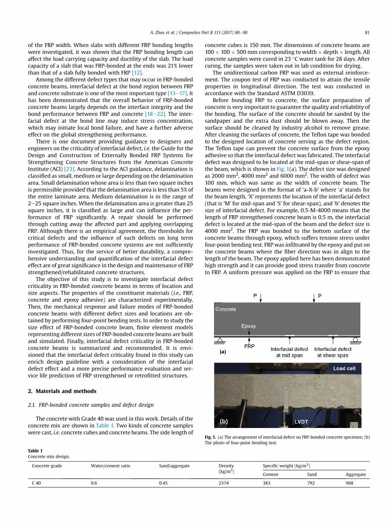
Before bonding FRP to concrete, the surface preparation ofconcrete is very important to guarantee the quality and reliability ofthe bonding. The surface of the concrete should be sanded by thesandpaper and the extra dust should be blown away. Then thesurface should be cleaned by industry alcohol to remove grease.After cleaning the surfaces of concrete, the Teflon tape was bondedto the designed location of concrete serving as the defect region.The Teflon tape can prevent the concrete surface from the epoxyadhesive so that the interfacial defect was fabricated. The interfacialdefect was designed to be located at the mid-span or shear-span ofthe beam, which is shown in Fig. 1(a). The defect size was designedas 2000 mm2, 4000 mm2 and 6000 mm2. The width of defect was100 mm, which was same as the width of concrete beam. Thebeams were designed in the format of ‘a-X-b’ where ‘a’ stands forthe beam length, ‘X’ represents the location of the interfacial defect(that is ‘M’ for mid-span and ‘S’ for shear-span), and ‘b’ denotes thesize of interfacial defect. For example, 0.5-M-4000 means that thelength of FRP strengthened concrete beam is 0.5 m, the interfacialdefect is located at the mid-span of the beam and the defect size is4000 mm2. The FRP was bonded to the bottom surface of theconcrete beams through epoxy, which suffers tension stress underfour-point bending test. FRPwas infiltrated by the epoxy and put onthe concrete beams where the fiber direction was in align to thelength of the beam. The epoxy applied here has been demonstratedhigh strength and it can provide good stress transfer from concreteto FRP. A uniform pressure was applied on the FRP to ensure that
Density(kg/m3)
Specific weight (kg/m3)
Cement Sand Aggregate
2374 383 792 968
Fig. 1. (a) The arrangement of interfacial defect on FRP-bonded concrete specimen; (b)The photo of four-point bending test.
A. Zhou et al. / Composites Part B 113 (2017) 80e9082
the FRP and concrete were well bonded excluding the Teflon tapearea. After 7 days curing, the FRP-bonded concrete beams wereready for test.
2.2. Test instrumentation
The concrete cubes were under compressive test to determinethe properties of concrete. Before testing, the dimensions of con-crete cube should be measured and the concrete cube should beplaced at the center of sample stage. The loading speed wasadopted as 13.5 kN/s according to the British Standard BS EN 12390.The load kept increasing until it reached the maximum value. Thecompressive strength of concrete can be calculated based on thedimensions and the load data acquired from the material testsystem.
The four-point bending test setup was used in this program. Thesupport span length was 300 mm and the load span was 150 mm.The FRP-bonded concrete beams were loaded by a 100 kN actuator.The load was applied monotonically under displacement control atrate of 0.5 mm/min until failure. Two linear variable displacementtransducers (LVDTs) were put in themiddle of front and back side ofbeams to measure the mid-span displacement. Meanwhile, onestrain gauge was bonded to the middle of the FRP and the other sixstrain gauges were evenly bonded to the left and right part of FRPsurface to measure the FRP strain variations. The photo of four-point bending test setup is shown in Fig. 1(b). During the test, theload, mid-span displacement and FRP strain variations weremeasured and recorded simultaneously through TDS-303 DataLogger. All FRP-bonded concrete samples with different defectdesign were tested with the identical instrumentation.
3. Finite element modeling
The numerical analysis is carried out using the ABAQUS FE(finite element) software [24]. The boundary conditions, mechan-ical properties and load conditions of FE models are set based onthe reported experiment in literature. The detailed information ofthe experimental specimen is given in Table 2, and the explicitsetup of experimental test can be found in Ref. [25].
3.1. Modeling of concrete
The concrete is modeled using the plane stress element CPS4 (4-
Table 2Geometry and material properties of beam models.
Beam details Parameters Value
Beam dimensions Span l (mm) 3000Width bc (mm) 203Depth d (mm) 406
Concrete Cylinder compressive strength fc0 (MPa) 37.2Elastic modulus Ec (MPa) 28850Tensile Strength ft (MPa) 2.86
Steel reinforcement Tension bars/yield strength fyt (Mpa) 2f16/440Compression bars/yield strength fyc (Mpa) 2f9.5/440Stirrups/yield strength of stirrups fyv (MPa) 7@102/596Elastic modulus of all steel bars Es (GPa) 200
FRP reinforcement Thickness tf (mm) 1.19Width bf (mm) 50Length Lf (mm) 2744Tensile strength ffu (MPa) 2400Elastic modulus Ef (GPa) 155
Note: 1 In the symbol xfy, x represents the number of the tension/compression barsand y represents the diameter of the tension/compression bars. 2 In symbol x@y, xstands for the diameter of the stirrups and y stands for the space between stirrupsalong the entire beam span.
node bilinear). The concrete damaged plasticity model in ABAQUSis adopted to define the compressive and tensile behavior of con-crete. The Poisson's ratio and the dilation angle for the concrete areset as 0.2 and 35�, respectively. For the concrete under uniaxialcompression, the stress-strain relationship is defined based onSaenz's model [26], which can be described as follows:
s ¼ aε
1þ��
aεpsp
�� 2
��ε
εp
�þ�
ε
εp
�2 (1)
where s is the compressive stress and ε is the correspondingcompressive strain; sp is the maximum compressive stress ofconcrete which is set to compressive strength fc0 and the εp is thecorresponding strain; a is the initial tangent modulus which is setas the elastic modulus of concrete Ec in absence of test data. Theelastic modulus of concrete is estimated following the equation
from ACI guideline, Ec ¼ 4730ffiffiffiffiffifc0
q[27].
The tensile behavior of concrete is defined as linear elastic up tothe tensile strength (ft), which can be estimated from the CEB-FIPequations [28]:
ft ¼ 1:4��f 0c � 8
10
23 (2)
The post-failure tension stiffening model of concrete is thendetermined by the tension stiffening factor b and the tensilestrength ft [29e31]. The tension stiffening factor b can be deter-mined by the following equation:
b ¼ exp�� 1100ðεct � εcrÞ
�Es200
��(3)
where Es is the elastic modulus of reinforcement, εcr is the concretestrain at cracking and εct is the corresponding tensile strain.
The post-failure tensile stress-strain behavior then can bedetermined as:
sct ¼ bft (4)
where sct is the tensile stress corresponding to the tensile strainεct.
3.2. Modeling of steel and FRP reinforcements
The truss element T2D2 (2-node linear displacement) is used tomodel both the steel and FRP reinforcements. The nonlinearbehavior of steel reinforcement is modeled as linear elastic up toyield stage, beyond which it is fully plastic. The FRP reinforcementis assumed to be linear elastic to failure, and the rupture point is setas the maximum tensile strength of the FRP.
3.3. Modeling of FRP-concrete interface
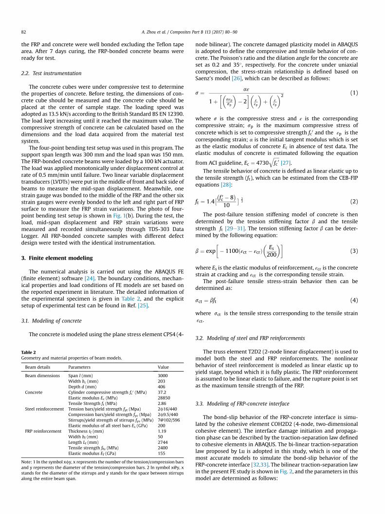
The bond-slip behavior of the FRP-concrete interface is simu-lated by the cohesive element COH2D2 (4-node, two-dimensionalcohesive element). The interface damage initiation and propaga-tion phase can be described by the traction-separation law definedto cohesive elements in ABAQUS. The bi-linear traction-separationlaw proposed by Lu is adopted in this study, which is one of themost accurate models to simulate the bond-slip behavior of theFRP-concrete interface [32,33]. The bilinear traction-separation lawin the present FE study is shown in Fig. 2, and the parameters in thismodel are determined as follows:
Fig. 2. The bilinear traction-separation law used to define the bond-slip behaviorbetween FRP reinforcement and concrete.
A. Zhou et al. / Composites Part B 113 (2017) 80e90 83
t ¼ tmax ss0
when s � s0 (5)
t ¼tmax
�sf � s
�sf � s0
when s0 � s � sf (6)
t ¼ 0 when s � sf (7)
where
sf ¼2Gftmax
(8)
tmax ¼ 1:5bw � ft (9)
bw ¼
ffiffiffiffiffiffiffiffiffiffiffiffiffiffiffiffiffiffiffiffiffiffiffiffiffiffi�2:25� bf
bc
��1:25þ bf
bc
�vuuuuuut (10)
s0 ¼ 0:0195b2w �ffiffiffift
p(11)
inwhich bf and bc are the width of FRP reinforcement and concretebeam, respectively; bw is thewidth ratio between FRP and concreteand Gf is the interfacial fracture energy which can be written as:
Gf ¼ 0:308b2w �ffiffiffift
p(12)
Table 3The mechanical properties of FRP.
Properties Values Notes
Tensile strength 3.69 GPa The test followed the guideline of ASTM D3039Ultimate strain 0.0158Elastic modulus 234 GPaThickness 0.166 mm
3.4. Specimen design
In total, fourteen beam models are built in ABAQUS, which canbe divided into three groups for different purposes. One FRP-bonded reinforced concrete beam FE model, i.e. 3-M-0 (3-S-0), isdesigned exactly as the experimental setup to validate the FEsimulation scheme against the experimental results. Six FRP-bonded reinforced concrete beam models in 3-m group aredesigned based on the reference case and they contain differentdefect arrangements at FRP-concrete interface. Beam models 3-M-6000, 3-M-12000 and 3-M-24000 refer to that the defect is locatedat mid-span with the size of 6000 mm2, 12000 mm2 and24000 mm2, respectively. Such defect size is designed based on thethresholds given by ACI 440.2R to evaluate the criticality of the
delamination between external FRP reinforcement and concrete. Inorder to investigate the effect of defect criticality in terms of loca-tion, beam models 3-S-6000, 3-S-12000 and 3-S-24000 are builtreferring to the samples containing shear-span defect. To furtherstudy the effect of beam length on the interfacial defect criticality,seven 6-m beam models, 6-M-0 (6-S-0), 6-M-6000, 6-M-12000, 6-M-24000, 6-S-6000, 6-S-12000 and 6-S-24000 are built. Thereinforcement setting and defect design are the same as those of 3-m group. Both the longitudinal reinforcement arrangement andcross-section design are the same as the experimental specimen soas to minimize the influence caused by other factors.
4. Results and discussions
4.1. Experimental results of FRP-bonded concrete beams
The compressive test is conducted with concrete cubes. Thecompressive strength and elastic modulus of concrete are 51.3 MPaand 29.7 GPa, respectively. The cracks in concrete under compres-sion are in parallel to the applied load direction. The mechanicalproperties of FRP under tensile test are shown in Table 3. The tensilestrength of FRP is 3.69 GPa (Standard deviation: 0.33 GPa). Withsuch high tensile strength, FRP can provide efficient reinforcementfor concrete beams. The epoxy is to integrate concrete and FRPalong the interface. The epoxy used here is high strength and highmodulus. The mechanical properties of epoxy are shown in Table 4.
The effect of interfacial defect is characterized by themechanicalproperties of FRP-bonded concrete beams. The load-displacementbehavior of FPR-bonded concrete beams containing interfacial de-fects at mid-span is shown in Fig. 3. The unstrengthened beamshows a linear response until peak beyond which a sudden loaddrop is reached, accompanied by the failure of the beam. Thestrengthened beams exhibit a similar response at the elastic stage.The load rises with the increase of mid-span displacement. Oncethe concrete reaches its stress limit, the load-displacement relationswitches to cracking stage in which the stiffness is lower than thatof elastic stage. Then, a linear ascent load-displacement behavior(which is defined to ultimate stage) is followed by a sudden loaddecline immediately after the peak load is reached, in which thefailure happens. FRP-bonded concrete specimen in different stagesis shown in Fig. 4. In the elastic stage, concrete is intact and thecracks occur in concrete once the concrete is beyond its stress limit.In cracking stage, the cracks propagate and FRP sheet withstandshigh tensile stress. Concrete at compression region has not reachedthe limit strain and cracks propagate to the top of the beam, whichcan be seen in Fig. 4 (b). Due to the presence of shear force, theconcrete substrate slips slowly with the FRP. In ultimate stage,cracks continue to propagate and the ascending load-displacementbehavior of specimen is attributed to the bond performance be-tween concrete and FRP.With the increase of load, the slip betweenconcrete and FRP reaches the limit and the specimen abruptly failsby the intermediate crack induced debonding.
The mechanical properties of FRP-bonded concrete beams withdifferent arrangements of interfacial defect are shown in Table 5.The load capacity of FRP-bonded concrete beams is an importantparameter indicating the mechanical property enhancement. The
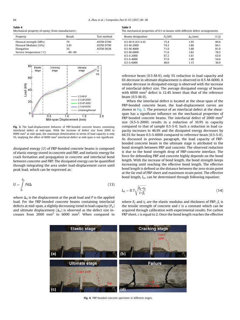
Table 4Mechanical property of epoxy (from manufacturer).
Property Result Test method
Flexural strength (MPa) 79 ASTM D790Flexural Modulus (GPa) 3.45 ASTM D790Elongation 3% ASTM D638Service temperature (�C) �40e60 e
Fig. 3. The load-displacement behavior of FRP-bonded concrete beams containinginterfacial defect at mid-span. With the increase of defect size from 2000 to6000 mm2 at mid-span, the maximum deterioration in terms of load capacity is only5%, implying the effect of 6000 mm2 interfacial defect at mid-span is not significant.
Table 5The mechanical properties of 0.5-m beams with different defect arrangements.
Beams designation Pu(kN) Du(mm) U (J)
0.5-M-0 (0.5-S-0) 75.4 1.95 89.60.5-M-2000 74.3 1.86 84.10.5-M-4000 71.9 1.88 81.00.5-M-6000 71.6 1.82 78.50.5-S-2000 67.2 1.61 63.00.5-S-4000 57.9 1.49 54.60.5-S-6000 40.0 1.15 30.9
A. Zhou et al. / Composites Part B 113 (2017) 80e9084
dissipated energy (U) of FRP-bonded concrete beams is composedof elastic energy stored in concrete and FRP, and inelastic energy forcrack formation and propagation in concrete and interfacial bondbetween concrete and FRP. The dissipated energy can be quantifiedthrough integrating the area under load-displacement curve untilpeak load, which can be expressed as:
U ¼ZDu
0
PdD (13)
where Du is the displacement at the peak load and P is the appliedload. For the FRP-bonded concrete beams containing interfacialdefects at mid-span, a slightly decreasing trend in load capacity (Pu)and ultimate displacement (Du) is observed as the defect size in-creases from 2000 mm2 to 6000 mm2. When compared to
Fig. 4. FRP-bonded concrete sp
reference beam (0.5-M-0), only 5% reduction in load capacity and6% decrease in ultimate displacement is observed in 0.5-M-6000. Asimilar decrease in dissipated energy is observed with the increaseof interfacial defect size. The average dissipated energy of beamswith 6000 mm2 defect is 12.4% lower than that of the referencebeam (0.5-M-0).
When the interfacial defect is located at the shear-span of theFRP-bonded concrete beam, the load-displacement curves areshown in Fig. 5. The presence of an interfacial defect at the shear-span has a significant influence on the mechanical properties ofFRP-bonded concrete beams. The interfacial defect of 2000 mm2
size (0.5-S-2000) results in a reduction of 10.9% in capacitycompared to that of sample 0.5-S-0. Such a reduction in load ca-pacity increases to 46.9% and the dissipated energy decreases by66.5% for beam 0.5-S-6000 compared to reference beam (0.5-S-0).As discussed in previous paragraph, the load capacity of FRP-bonded concrete beam in the ultimate stage is attributed to thebond strength between FRP and concrete. The observed reductionis due to the bond strength drop of FRP-concrete interface. Theforce for debonding FRP and concrete highly depends on the bondlength. With the increase of bond length, the bond strength keepsincreasing until reaching the effective bond length. The effectivebond length is defined as the distance between the zero strain pointat the far end of FRP sheet and maximum strain point. The effectivebond length, Le, can be determined through following equation:
Le ¼ 0:7
ffiffiffiffiffiffiffiffiffiffiffiEf,tfc,ft
s(14)
where Ef and tf are the elastic modulus and thickness of FRP; ft isthe tensile strength of concrete and c is a constant which can beacquired through calibration with experimental results. For carbonFRP sheet, c is equal to 2. Once the bond length reaches the effective
ecimen in different stages.
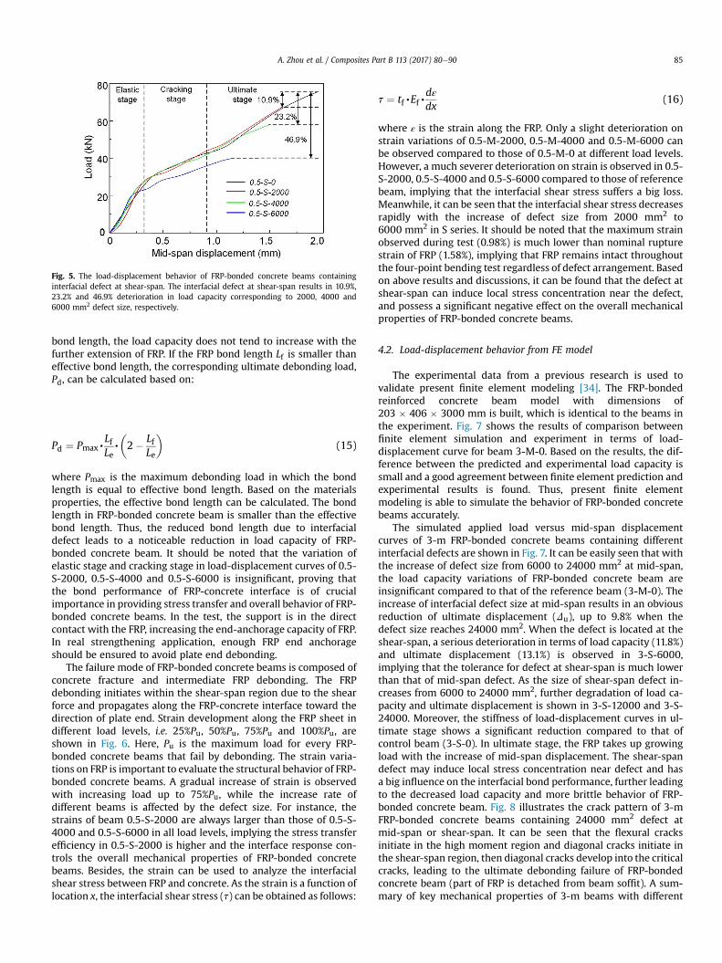
Fig. 5. The load-displacement behavior of FRP-bonded concrete beams containinginterfacial defect at shear-span. The interfacial defect at shear-span results in 10.9%,23.2% and 46.9% deterioration in load capacity corresponding to 2000, 4000 and6000 mm2 defect size, respectively.
A. Zhou et al. / Composites Part B 113 (2017) 80e90 85
bond length, the load capacity does not tend to increase with thefurther extension of FRP. If the FRP bond length Lf is smaller thaneffective bond length, the corresponding ultimate debonding load,Pd, can be calculated based on:
Pd ¼ Pmax,LfLe,
�2� Lf
Le
�(15)
where Pmax is the maximum debonding load in which the bondlength is equal to effective bond length. Based on the materialsproperties, the effective bond length can be calculated. The bondlength in FRP-bonded concrete beam is smaller than the effectivebond length. Thus, the reduced bond length due to interfacialdefect leads to a noticeable reduction in load capacity of FRP-bonded concrete beam. It should be noted that the variation ofelastic stage and cracking stage in load-displacement curves of 0.5-S-2000, 0.5-S-4000 and 0.5-S-6000 is insignificant, proving thatthe bond performance of FRP-concrete interface is of crucialimportance in providing stress transfer and overall behavior of FRP-bonded concrete beams. In the test, the support is in the directcontact with the FRP, increasing the end-anchorage capacity of FRP.In real strengthening application, enough FRP end anchorageshould be ensured to avoid plate end debonding.
The failure mode of FRP-bonded concrete beams is composed ofconcrete fracture and intermediate FRP debonding. The FRPdebonding initiates within the shear-span region due to the shearforce and propagates along the FRP-concrete interface toward thedirection of plate end. Strain development along the FRP sheet indifferent load levels, i.e. 25%Pu, 50%Pu, 75%Pu and 100%Pu, areshown in Fig. 6. Here, Pu is the maximum load for every FRP-bonded concrete beams that fail by debonding. The strain varia-tions on FRP is important to evaluate the structural behavior of FRP-bonded concrete beams. A gradual increase of strain is observedwith increasing load up to 75%Pu, while the increase rate ofdifferent beams is affected by the defect size. For instance, thestrains of beam 0.5-S-2000 are always larger than those of 0.5-S-4000 and 0.5-S-6000 in all load levels, implying the stress transferefficiency in 0.5-S-2000 is higher and the interface response con-trols the overall mechanical properties of FRP-bonded concretebeams. Besides, the strain can be used to analyze the interfacialshear stress between FRP and concrete. As the strain is a function oflocation x, the interfacial shear stress (t) can be obtained as follows:
t ¼ tf,Ef,dεdx
(16)
where ε is the strain along the FRP. Only a slight deterioration onstrain variations of 0.5-M-2000, 0.5-M-4000 and 0.5-M-6000 canbe observed compared to those of 0.5-M-0 at different load levels.However, a much severer deterioration on strain is observed in 0.5-S-2000, 0.5-S-4000 and 0.5-S-6000 compared to those of referencebeam, implying that the interfacial shear stress suffers a big loss.Meanwhile, it can be seen that the interfacial shear stress decreasesrapidly with the increase of defect size from 2000 mm2 to6000 mm2 in S series. It should be noted that the maximum strainobserved during test (0.98%) is much lower than nominal rupturestrain of FRP (1.58%), implying that FRP remains intact throughoutthe four-point bending test regardless of defect arrangement. Basedon above results and discussions, it can be found that the defect atshear-span can induce local stress concentration near the defect,and possess a significant negative effect on the overall mechanicalproperties of FRP-bonded concrete beams.
4.2. Load-displacement behavior from FE model
The experimental data from a previous research is used tovalidate present finite element modeling [34]. The FRP-bondedreinforced concrete beam model with dimensions of203 � 406 � 3000 mm is built, which is identical to the beams inthe experiment. Fig. 7 shows the results of comparison betweenfinite element simulation and experiment in terms of load-displacement curve for beam 3-M-0. Based on the results, the dif-ference between the predicted and experimental load capacity issmall and a good agreement between finite element prediction andexperimental results is found. Thus, present finite elementmodeling is able to simulate the behavior of FRP-bonded concretebeams accurately.
The simulated applied load versus mid-span displacementcurves of 3-m FRP-bonded concrete beams containing differentinterfacial defects are shown in Fig. 7. It can be easily seen that withthe increase of defect size from 6000 to 24000 mm2 at mid-span,the load capacity variations of FRP-bonded concrete beam areinsignificant compared to that of the reference beam (3-M-0). Theincrease of interfacial defect size at mid-span results in an obviousreduction of ultimate displacement (Du), up to 9.8% when thedefect size reaches 24000 mm2. When the defect is located at theshear-span, a serious deterioration in terms of load capacity (11.8%)and ultimate displacement (13.1%) is observed in 3-S-6000,implying that the tolerance for defect at shear-span is much lowerthan that of mid-span defect. As the size of shear-span defect in-creases from 6000 to 24000 mm2, further degradation of load ca-pacity and ultimate displacement is shown in 3-S-12000 and 3-S-24000. Moreover, the stiffness of load-displacement curves in ul-timate stage shows a significant reduction compared to that ofcontrol beam (3-S-0). In ultimate stage, the FRP takes up growingload with the increase of mid-span displacement. The shear-spandefect may induce local stress concentration near defect and hasa big influence on the interfacial bond performance, further leadingto the decreased load capacity and more brittle behavior of FRP-bonded concrete beam. Fig. 8 illustrates the crack pattern of 3-mFRP-bonded concrete beams containing 24000 mm2 defect atmid-span or shear-span. It can be seen that the flexural cracksinitiate in the high moment region and diagonal cracks initiate inthe shear-span region, then diagonal cracks develop into the criticalcracks, leading to the ultimate debonding failure of FRP-bondedconcrete beam (part of FRP is detached from beam soffit). A sum-mary of key mechanical properties of 3-m beams with different
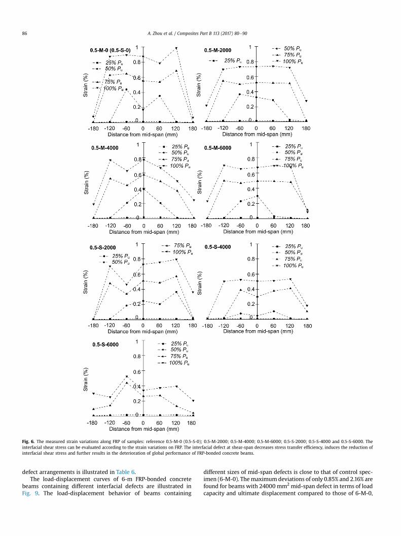
Fig. 6. The measured strain variations along FRP of samples: reference 0.5-M-0 (0.5-S-0); 0.5-M-2000; 0.5-M-4000; 0.5-M-6000; 0.5-S-2000; 0.5-S-4000 and 0.5-S-6000. Theinterfacial shear stress can be evaluated according to the strain variations on FRP. The interfacial defect at shear-span decreases stress transfer efficiency, induces the reduction ofinterfacial shear stress and further results in the deterioration of global performance of FRP-bonded concrete beams.
A. Zhou et al. / Composites Part B 113 (2017) 80e9086
defect arrangements is illustrated in Table 6.The load-displacement curves of 6-m FRP-bonded concrete
beams containing different interfacial defects are illustrated inFig. 9. The load-displacement behavior of beams containing
different sizes of mid-span defects is close to that of control spec-imen (6-M-0). Themaximumdeviations of only 0.85% and 2.16% arefound for beams with 24000 mm2 mid-span defect in terms of loadcapacity and ultimate displacement compared to those of 6-M-0,
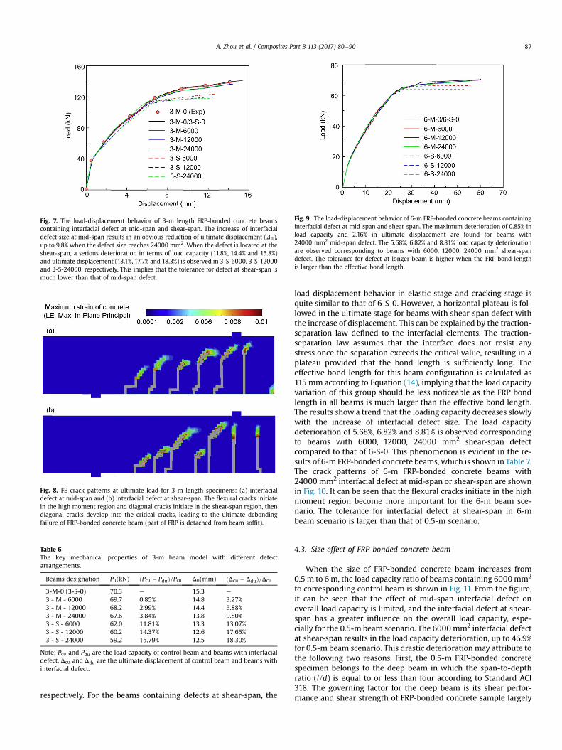
Fig. 7. The load-displacement behavior of 3-m length FRP-bonded concrete beamscontaining interfacial defect at mid-span and shear-span. The increase of interfacialdefect size at mid-span results in an obvious reduction of ultimate displacement (Du),up to 9.8% when the defect size reaches 24000 mm2. When the defect is located at theshear-span, a serious deterioration in terms of load capacity (11.8%, 14.4% and 15.8%)and ultimate displacement (13.1%, 17.7% and 18.3%) is observed in 3-S-6000, 3-S-12000and 3-S-24000, respectively. This implies that the tolerance for defect at shear-span ismuch lower than that of mid-span defect.
Fig. 8. FE crack patterns at ultimate load for 3-m length specimens: (a) interfacialdefect at mid-span and (b) interfacial defect at shear-span. The flexural cracks initiatein the high moment region and diagonal cracks initiate in the shear-span region, thendiagonal cracks develop into the critical cracks, leading to the ultimate debondingfailure of FRP-bonded concrete beam (part of FRP is detached from beam soffit).
Table 6The key mechanical properties of 3-m beam model with different defectarrangements.
Beams designation Pu(kN) ðPcu � PduÞ=Pcu Du(mm) ðDcu � DduÞ=Dcu
3-M-0 (3-S-0) 70.3 e 15.3 e
3 - M - 6000 69.7 0.85% 14.8 3.27%3 - M - 12000 68.2 2.99% 14.4 5.88%3 - M - 24000 67.6 3.84% 13.8 9.80%3 - S - 6000 62.0 11.81% 13.3 13.07%3 - S - 12000 60.2 14.37% 12.6 17.65%3 - S - 24000 59.2 15.79% 12.5 18.30%
Note: Pcu and Pdu are the load capacity of control beam and beams with interfacialdefect, Dcu and Ddu are the ultimate displacement of control beam and beams withinterfacial defect.
Fig. 9. The load-displacement behavior of 6-m FRP-bonded concrete beams containinginterfacial defect at mid-span and shear-span. The maximum deterioration of 0.85% inload capacity and 2.16% in ultimate displacement are found for beams with24000 mm2 mid-span defect. The 5.68%, 6.82% and 8.81% load capacity deteriorationare observed corresponding to beams with 6000, 12000, 24000 mm2 shear-spandefect. The tolerance for defect at longer beam is higher when the FRP bond lengthis larger than the effective bond length.
A. Zhou et al. / Composites Part B 113 (2017) 80e90 87
respectively. For the beams containing defects at shear-span, the
load-displacement behavior in elastic stage and cracking stage isquite similar to that of 6-S-0. However, a horizontal plateau is fol-lowed in the ultimate stage for beams with shear-span defect withthe increase of displacement. This can be explained by the traction-separation law defined to the interfacial elements. The traction-separation law assumes that the interface does not resist anystress once the separation exceeds the critical value, resulting in aplateau provided that the bond length is sufficiently long. Theeffective bond length for this beam configuration is calculated as115 mm according to Equation (14), implying that the load capacityvariation of this group should be less noticeable as the FRP bondlength in all beams is much larger than the effective bond length.The results show a trend that the loading capacity decreases slowlywith the increase of interfacial defect size. The load capacitydeterioration of 5.68%, 6.82% and 8.81% is observed correspondingto beams with 6000, 12000, 24000 mm2 shear-span defectcompared to that of 6-S-0. This phenomenon is evident in the re-sults of 6-m FRP-bonded concrete beams, which is shown in Table 7.The crack patterns of 6-m FRP-bonded concrete beams with24000 mm2 interfacial defect at mid-span or shear-span are shownin Fig. 10. It can be seen that the flexural cracks initiate in the highmoment region become more important for the 6-m beam sce-nario. The tolerance for interfacial defect at shear-span in 6-mbeam scenario is larger than that of 0.5-m scenario.
4.3. Size effect of FRP-bonded concrete beam
When the size of FRP-bonded concrete beam increases from0.5 m to 6m, the load capacity ratio of beams containing 6000mm2
to corresponding control beam is shown in Fig. 11. From the figure,it can be seen that the effect of mid-span interfacial defect onoverall load capacity is limited, and the interfacial defect at shear-span has a greater influence on the overall load capacity, espe-cially for the 0.5-m beam scenario. The 6000 mm2 interfacial defectat shear-span results in the load capacity deterioration, up to 46.9%for 0.5-m beam scenario. This drastic deterioration may attribute tothe following two reasons. First, the 0.5-m FRP-bonded concretespecimen belongs to the deep beam in which the span-to-depthratio (l=d) is equal to or less than four according to Standard ACI318. The governing factor for the deep beam is its shear perfor-mance and shear strength of FRP-bonded concrete sample largely
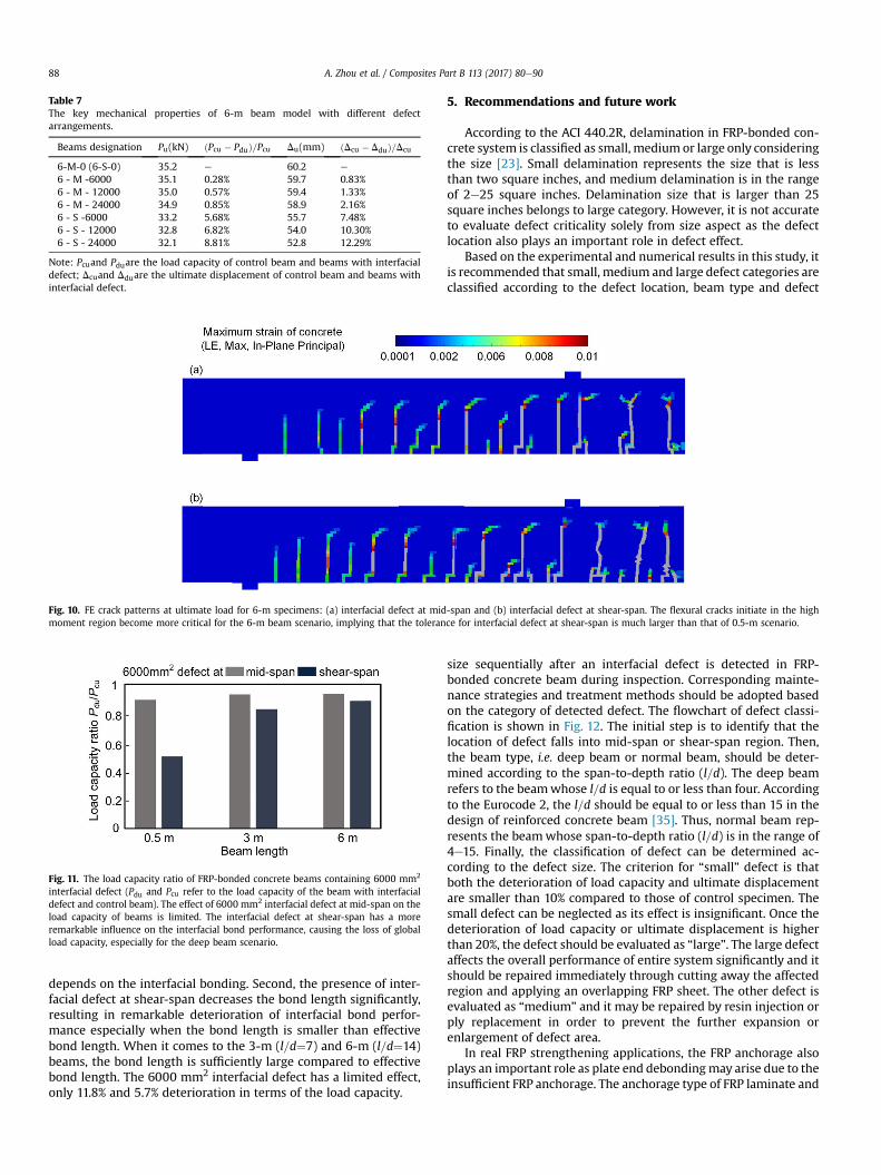
Table 7The key mechanical properties of 6-m beam model with different defectarrangements.
Beams designation Pu(kN) ðPcu � PduÞ=Pcu Du(mm) ðDcu � DduÞ=Dcu
6-M-0 (6-S-0) 35.2 e 60.2 e
6 - M -6000 35.1 0.28% 59.7 0.83%6 - M - 12000 35.0 0.57% 59.4 1.33%6 - M - 24000 34.9 0.85% 58.9 2.16%6 - S -6000 33.2 5.68% 55.7 7.48%6 - S - 12000 32.8 6.82% 54.0 10.30%6 - S - 24000 32.1 8.81% 52.8 12.29%
Note: Pcuand Pduare the load capacity of control beam and beams with interfacialdefect; Dcuand Dduare the ultimate displacement of control beam and beams withinterfacial defect.
Fig. 10. FE crack patterns at ultimate load for 6-m specimens: (a) interfacial defect at mid-span and (b) interfacial defect at shear-span. The flexural cracks initiate in the highmoment region become more critical for the 6-m beam scenario, implying that the tolerance for interfacial defect at shear-span is much larger than that of 0.5-m scenario.
Fig. 11. The load capacity ratio of FRP-bonded concrete beams containing 6000 mm2
interfacial defect (Pdu and Pcu refer to the load capacity of the beam with interfacialdefect and control beam). The effect of 6000 mm2 interfacial defect at mid-span on theload capacity of beams is limited. The interfacial defect at shear-span has a moreremarkable influence on the interfacial bond performance, causing the loss of globalload capacity, especially for the deep beam scenario.
A. Zhou et al. / Composites Part B 113 (2017) 80e9088
depends on the interfacial bonding. Second, the presence of inter-facial defect at shear-span decreases the bond length significantly,resulting in remarkable deterioration of interfacial bond perfor-mance especially when the bond length is smaller than effectivebond length. When it comes to the 3-m (l=d¼7) and 6-m (l=d¼14)beams, the bond length is sufficiently large compared to effectivebond length. The 6000 mm2 interfacial defect has a limited effect,only 11.8% and 5.7% deterioration in terms of the load capacity.
5. Recommendations and future work
According to the ACI 440.2R, delamination in FRP-bonded con-crete system is classified as small, medium or large only consideringthe size [23]. Small delamination represents the size that is lessthan two square inches, and medium delamination is in the rangeof 2e25 square inches. Delamination size that is larger than 25square inches belongs to large category. However, it is not accurateto evaluate defect criticality solely from size aspect as the defectlocation also plays an important role in defect effect.
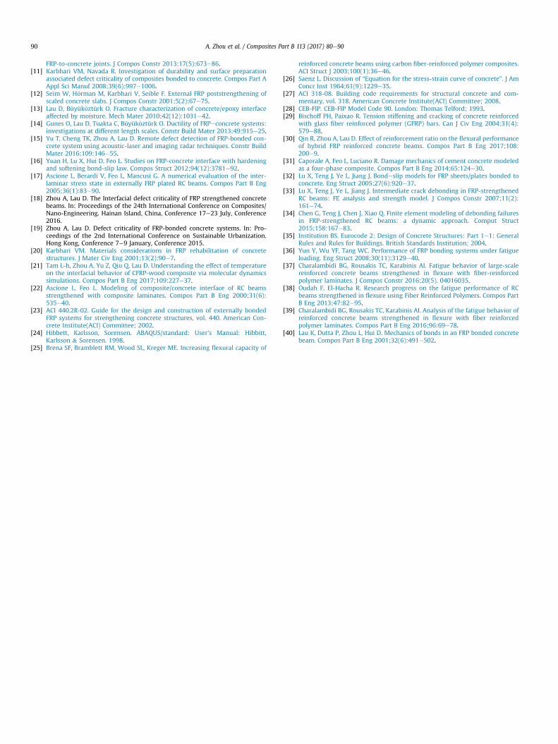
Based on the experimental and numerical results in this study, itis recommended that small, medium and large defect categories areclassified according to the defect location, beam type and defect
size sequentially after an interfacial defect is detected in FRP-bonded concrete beam during inspection. Corresponding mainte-nance strategies and treatment methods should be adopted basedon the category of detected defect. The flowchart of defect classi-fication is shown in Fig. 12. The initial step is to identify that thelocation of defect falls into mid-span or shear-span region. Then,the beam type, i.e. deep beam or normal beam, should be deter-mined according to the span-to-depth ratio (l=d). The deep beamrefers to the beamwhose l=d is equal to or less than four. Accordingto the Eurocode 2, the l=d should be equal to or less than 15 in thedesign of reinforced concrete beam [35]. Thus, normal beam rep-resents the beamwhose span-to-depth ratio (l=d) is in the range of4e15. Finally, the classification of defect can be determined ac-cording to the defect size. The criterion for “small” defect is thatboth the deterioration of load capacity and ultimate displacementare smaller than 10% compared to those of control specimen. Thesmall defect can be neglected as its effect is insignificant. Once thedeterioration of load capacity or ultimate displacement is higherthan 20%, the defect should be evaluated as “large”. The large defectaffects the overall performance of entire system significantly and itshould be repaired immediately through cutting away the affectedregion and applying an overlapping FRP sheet. The other defect isevaluated as “medium” and it may be repaired by resin injection orply replacement in order to prevent the further expansion orenlargement of defect area.
In real FRP strengthening applications, the FRP anchorage alsoplays an important role as plate end debondingmay arise due to theinsufficient FRP anchorage. The anchorage type of FRP laminate and
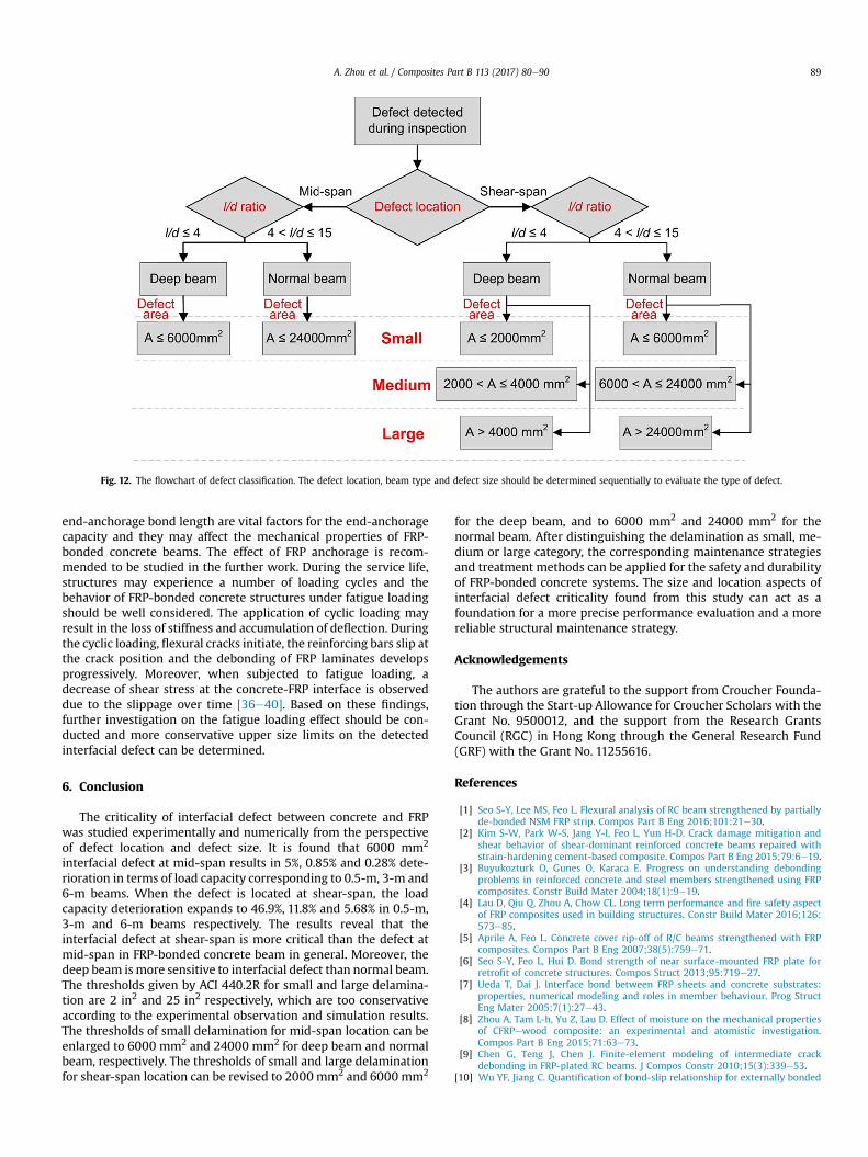
Fig. 12. The flowchart of defect classification. The defect location, beam type and defect size should be determined sequentially to evaluate the type of defect.
A. Zhou et al. / Composites Part B 113 (2017) 80e90 89
end-anchorage bond length are vital factors for the end-anchoragecapacity and they may affect the mechanical properties of FRP-bonded concrete beams. The effect of FRP anchorage is recom-mended to be studied in the further work. During the service life,structures may experience a number of loading cycles and thebehavior of FRP-bonded concrete structures under fatigue loadingshould be well considered. The application of cyclic loading mayresult in the loss of stiffness and accumulation of deflection. Duringthe cyclic loading, flexural cracks initiate, the reinforcing bars slip atthe crack position and the debonding of FRP laminates developsprogressively. Moreover, when subjected to fatigue loading, adecrease of shear stress at the concrete-FRP interface is observeddue to the slippage over time [36e40]. Based on these findings,further investigation on the fatigue loading effect should be con-ducted and more conservative upper size limits on the detectedinterfacial defect can be determined.
6. Conclusion
The criticality of interfacial defect between concrete and FRPwas studied experimentally and numerically from the perspectiveof defect location and defect size. It is found that 6000 mm2
interfacial defect at mid-span results in 5%, 0.85% and 0.28% dete-rioration in terms of load capacity corresponding to 0.5-m, 3-m and6-m beams. When the defect is located at shear-span, the loadcapacity deterioration expands to 46.9%, 11.8% and 5.68% in 0.5-m,3-m and 6-m beams respectively. The results reveal that theinterfacial defect at shear-span is more critical than the defect atmid-span in FRP-bonded concrete beam in general. Moreover, thedeep beam ismore sensitive to interfacial defect than normal beam.The thresholds given by ACI 440.2R for small and large delamina-tion are 2 in2 and 25 in2 respectively, which are too conservativeaccording to the experimental observation and simulation results.The thresholds of small delamination for mid-span location can beenlarged to 6000 mm2 and 24000 mm2 for deep beam and normalbeam, respectively. The thresholds of small and large delaminationfor shear-span location can be revised to 2000 mm2 and 6000 mm2
for the deep beam, and to 6000 mm2 and 24000 mm2 for thenormal beam. After distinguishing the delamination as small, me-dium or large category, the corresponding maintenance strategiesand treatment methods can be applied for the safety and durabilityof FRP-bonded concrete systems. The size and location aspects ofinterfacial defect criticality found from this study can act as afoundation for a more precise performance evaluation and a morereliable structural maintenance strategy.
Acknowledgements
The authors are grateful to the support from Croucher Founda-tion through the Start-up Allowance for Croucher Scholars with theGrant No. 9500012, and the support from the Research GrantsCouncil (RGC) in Hong Kong through the General Research Fund(GRF) with the Grant No. 11255616.
References
[1] Seo S-Y, Lee MS, Feo L. Flexural analysis of RC beam strengthened by partiallyde-bonded NSM FRP strip. Compos Part B Eng 2016;101:21e30.
[2] Kim S-W, Park W-S, Jang Y-I, Feo L, Yun H-D. Crack damage mitigation andshear behavior of shear-dominant reinforced concrete beams repaired withstrain-hardening cement-based composite. Compos Part B Eng 2015;79:6e19.
[3] Buyukozturk O, Gunes O, Karaca E. Progress on understanding debondingproblems in reinforced concrete and steel members strengthened using FRPcomposites. Constr Build Mater 2004;18(1):9e19.
[4] Lau D, Qiu Q, Zhou A, Chow CL. Long term performance and fire safety aspectof FRP composites used in building structures. Constr Build Mater 2016;126:573e85.
[5] Aprile A, Feo L. Concrete cover rip-off of R/C beams strengthened with FRPcomposites. Compos Part B Eng 2007;38(5):759e71.
[6] Seo S-Y, Feo L, Hui D. Bond strength of near surface-mounted FRP plate forretrofit of concrete structures. Compos Struct 2013;95:719e27.
[7] Ueda T, Dai J. Interface bond between FRP sheets and concrete substrates:properties, numerical modeling and roles in member behaviour. Prog StructEng Mater 2005;7(1):27e43.
[8] Zhou A, Tam L-h, Yu Z, Lau D. Effect of moisture on the mechanical propertiesof CFRPewood composite: an experimental and atomistic investigation.Compos Part B Eng 2015;71:63e73.
[9] Chen G, Teng J, Chen J. Finite-element modeling of intermediate crackdebonding in FRP-plated RC beams. J Compos Constr 2010;15(3):339e53.
[10] Wu YF, Jiang C. Quantification of bond-slip relationship for externally bonded
A. Zhou et al. / Composites Part B 113 (2017) 80e9090
FRP-to-concrete joints. J Compos Constr 2013;17(5):673e86.[11] Karbhari VM, Navada R. Investigation of durability and surface preparation
associated defect criticality of composites bonded to concrete. Compos Part AAppl Sci Manuf 2008;39(6):997e1006.
[12] Seim W, H€orman M, Karbhari V, Seible F. External FRP poststrengthening ofscaled concrete slabs. J Compos Constr 2001;5(2):67e75.
[13] Lau D, Büyük€oztürk O. Fracture characterization of concrete/epoxy interfaceaffected by moisture. Mech Mater 2010;42(12):1031e42.
[14] Gunes O, Lau D, Tuakta C, Büyük€oztürk O. Ductility of FRPeconcrete systems:investigations at different length scales. Constr Build Mater 2013;49:915e25.
[15] Yu T, Cheng TK, Zhou A, Lau D. Remote defect detection of FRP-bonded con-crete system using acoustic-laser and imaging radar techniques. Constr BuildMater 2016;109:146e55.
[16] Yuan H, Lu X, Hui D, Feo L. Studies on FRP-concrete interface with hardeningand softening bond-slip law. Compos Struct 2012;94(12):3781e92.
[17] Ascione L, Berardi V, Feo L, Mancusi G. A numerical evaluation of the inter-laminar stress state in externally FRP plated RC beams. Compos Part B Eng2005;36(1):83e90.
[18] Zhou A, Lau D. The Interfacial defect criticality of FRP strengthened concretebeams. In: Proceedings of the 24th International Conference on Composites/Nano-Engineering. Hainan Island, China, Conference 17e23 July, Conference2016.
[19] Zhou A, Lau D. Defect criticality of FRP-bonded concrete systems. In: Pro-ceedings of the 2nd International Conference on Sustainable Urbanization.Hong Kong, Conference 7e9 January, Conference 2015.
[20] Karbhari VM. Materials considerations in FRP rehabilitation of concretestructures. J Mater Civ Eng 2001;13(2):90e7.
[21] Tam L-h, Zhou A, Yu Z, Qiu Q, Lau D. Understanding the effect of temperatureon the interfacial behavior of CFRP-wood composite via molecular dynamicssimulations. Compos Part B Eng 2017;109:227e37.
[22] Ascione L, Feo L. Modeling of composite/concrete interface of RC beamsstrengthened with composite laminates. Compos Part B Eng 2000;31(6):535e40.
[23] ACI 440.2R-02. Guide for the design and construction of externally bondedFRP systems for strengthening concrete structures, vol. 440. American Con-crete Institute(ACI) Committee; 2002.
[24] Hibbett, Karlsson, Sorensen. ABAQUS/standard: User's Manual: Hibbitt,Karlsson & Sorensen. 1998.
[25] Brena SF, Bramblett RM, Wood SL, Kreger ME. Increasing flexural capacity of
reinforced concrete beams using carbon fiber-reinforced polymer composites.ACI Struct J 2003;100(1):36e46.
[26] Saenz L. Discussion of “Equation for the stress-strain curve of concrete”. J AmConcr Inst 1964;61(9):1229e35.
[27] ACI 318-08. Building code requirements for structural concrete and com-mentary, vol. 318. American Concrete Institute(ACI) Committee; 2008.
[28] CEB-FIP. CEB-FIP Model Code 90. London: Thomas Telford; 1993.[29] Bischoff PH, Paixao R. Tension stiffening and cracking of concrete reinforced
with glass fiber reinforced polymer (GFRP) bars. Can J Civ Eng 2004;31(4):579e88.
[30] Qin R, Zhou A, Lau D. Effect of reinforcement ratio on the flexural performanceof hybrid FRP reinforced concrete beams. Compos Part B Eng 2017;108:200e9.
[31] Caporale A, Feo L, Luciano R. Damage mechanics of cement concrete modeledas a four-phase composite. Compos Part B Eng 2014;65:124e30.
[32] Lu X, Teng J, Ye L, Jiang J. Bondeslip models for FRP sheets/plates bonded toconcrete. Eng Struct 2005;27(6):920e37.
[33] Lu X, Teng J, Ye L, Jiang J. Intermediate crack debonding in FRP-strengthenedRC beams: FE analysis and strength model. J Compos Constr 2007;11(2):161e74.
[34] Chen G, Teng J, Chen J, Xiao Q. Finite element modeling of debonding failuresin FRP-strengthened RC beams: a dynamic approach. Comput Struct2015;158:167e83.
[35] Institution BS. Eurocode 2: Design of Concrete Structures: Part 1e1: GeneralRules and Rules for Buildings. British Standards Institution; 2004.
[36] Yun Y, Wu YF, Tang WC. Performance of FRP bonding systems under fatigueloading. Eng Struct 2008;30(11):3129e40.
[37] Charalambidi BG, Rousakis TC, Karabinis AI. Fatigue behavior of large-scalereinforced concrete beams strengthened in flexure with fiber-reinforcedpolymer laminates. J Compos Constr 2016;20(5). 04016035.
[38] Oudah F, El-Hacha R. Research progress on the fatigue performance of RCbeams strengthened in flexure using Fiber Reinforced Polymers. Compos PartB Eng 2013;47:82e95.
[39] Charalambidi BG, Rousakis TC, Karabinis AI. Analysis of the fatigue behavior ofreinforced concrete beams strengthened in flexure with fiber reinforcedpolymer laminates. Compos Part B Eng 2016;96:69e78.
[40] Lau K, Dutta P, Zhou L, Hui D. Mechanics of bonds in an FRP bonded concretebeam. Compos Part B Eng 2001;32(6):491e502.